Solarstation S Technische Information für Montage und Betrieb
|
|
|
- Hedwig Holzmann
- vor 8 Jahren
- Abrufe
Transkript
1 PR Technische Änderungen vorbehalten Solarstation S Technische Information für Montage und Betrieb Solar station S Technical information for installation and operation Station solaire S Documentation technique pour le montage et la mise en service DE GB FR Meibes System-Technik GmbH Ringstraße 18 D Gerichshain Tel. + 49(0) Fax Internet: info@meibes.de

2 Inhalt 1 Sicherheitshinweise 1.1 Vorschriften/Richtlinien Bestimmungsgemäße Verwendung Erstinbetriebnahme Arbeiten an der Anlage Haftung 4 2 Technische Daten 5 3 Montage Wandmontage Absperrarmaturen Thermometerwechsel Sicherheitsventil Rückflussverhinderer Anschluss eines Ausdehnungsgefäßes (bauseits) Wärmeträgermedium 10 4 Druckprobe, Befüllen und Spülen der Anlage Druckprobe Spülen und Befüllen Entlüften Entleeren 12 5 Ausführungen Solarkreisregelung Bitte beachten: Die Montage- und Betriebsanleitung der Reglertyps liegt separat bei. 2

3 1. Sicherheitshinweise Lesen Sie vor der Montage diese Anleitung sorgfältig durch. Die Montage und Erstinbetriebnahme der Komplettstation darf nur von einer zugelassenen Fachfirma ausgeführt werden. Machen Sie sich vor Arbeitsbeginn mit allen Teilen und deren Handhabung vertraut. DE - Vor Gebrauch Montageanleitung lesen - Gefahr erhöhter Temperatur - Schnittgefahr - Gefahr elektrischer Spannung - Quetschgefahr - Sturzgefahr bei der Montage 1.1 Vorschriften/Richtlinien Beachten Sie die gültigen Unfallverhütungs-vorschriften, Umweltvorschriften und gesetzlichen Regeln für die Montage, Installation und den Betrieb. Des Weiteren die einschlägigen Richtlinien der DIN, EN, DVGW, VDI und VDE (inkl. Blitzschutz) sowie alle aktuellen relevanten länderspezifischen Normen, Gesetze und Richtlinien. Elektroanschluss: Elektrische Anschlussarbeiten dürfen nur durch qualifiziertes Elektrofachpersonal ausgeführt werden. Die VDE-Richtlinien und die Vorgaben des zuständigen EVU sind einzuhalten. Auszug: Thermische Solaranlagen und ihre Bauteile: DIN EN Sonnenkollektoren DIN EN Vorgefertigte Anlagen DIN EN Kundenspezifisch gefertigte Anlagen Elektrischer Anschluss: VDE 0100 Errichtung elektrischer Betriebsmittel, Erdung, Schutzleiter, Potential ausgleichsleiter VDE 0701 Instandsetzung, Änderung und Prüfung elektrischer Geräte VDE 0185 Allgemeines für das Errichten von Blitzschutzanlagen VDE 0190 Hauptpotentialausgleich von elektrischen Anlagen VDE 0855 Installation von Antennenanlagen (ist sinngemäß anzuwenden) Zusätzliche Hinweise: VDI 6002 AllgemeineGrundlagen, Systemtechnik und Anwendung im Wonungsbau VDI 6002 Anwendungen in Studentenwohnheimen, Seniorenheimen, Krankenhäusern, Hallenbädern und auf Campingplätzen 3

4 1. Sicherheitshinweise 1.2 Bestimmungsgemäße Verwendung Die beschriebenen Stationen sind nur mit geeigneter bzw. zugelassener Solarflüssigkeit zu betreiben. Es ist auf einen ausreichenden Frostschutzgehalt zu achten. Die Verwendung eines anderen Mediums ist nicht zulässig. Medientemperatur > 60 C (Verbrühungsgefahr) Soll- bzw. Befülldruck < Ansprechdruck der Sicherheitsarmatur Alle Absperrarmaturen dürfen nur im Servicefall und bei abgedeckten Kollektoren geschlossen werden, da ansonsten die Sicherheitsarmaturen ihre Wirkung verlieren. Vorsicht: Nehmen Sie keine Veränderungen an den elektrischen Bauteilen, der Konstruktion oder den hydraulischen Komponenten vor! Sie beeinträchtigen sonst die sichere Funktion der Anlage. 1.3 Erstinbetriebnahme Vor der Erstinbetriebnahme ist die Anlage auf Dichtheit, eine korrekte hydraulische Anbindung sowie sorgfältige und korrekte elektrische Anschlüsse zu prüfen. Des weiteren ist ein sorgfältiges bzw. bedarfsgerechtes Spülen gemäß DIN 4753 der Anlage durchzuführen. Die Erstinbetriebnahme hat durch eine geschulte Fachkraft zu erfolgen und ist schriftlich zu protokollieren. Darüber hinaus sind die Einstellwerte schriftlich festzuhalten. Die technische Dokumentation hat am Gerät zu verbleiben. 1.4 Arbeiten an der Anlage Die Anlage ist spannungsfrei zu schalten und auf Spannungsfreiheit zu kontrollieren (z.b. an der separaten Sicherung oder einem Hauptschalter). Anlage gegen Wiedereinschalten sichern. Die Kollektoren sind abzudecken, um das System abzukühlen. ACHTUNG: Verbrühungsgefahr: Medientemperatur > 60 C 1.5 Haftung Für diese Unterlage behalten wir uns alle Urheberrechte vor. Missbräuchliche Verwendung, insbesondere Vervielfältigung und Weitergabe an Dritte ist nicht gestattet. Diese Montage- und Bedienungsanleitung ist dem Kunden zu übergeben. Das ausführende bzw. zugelassene Gewerke (z.b.installateur) hat dem Kunden die Wirkungsweise und Bedienung des Gerätes verständlich zu erklären. 4

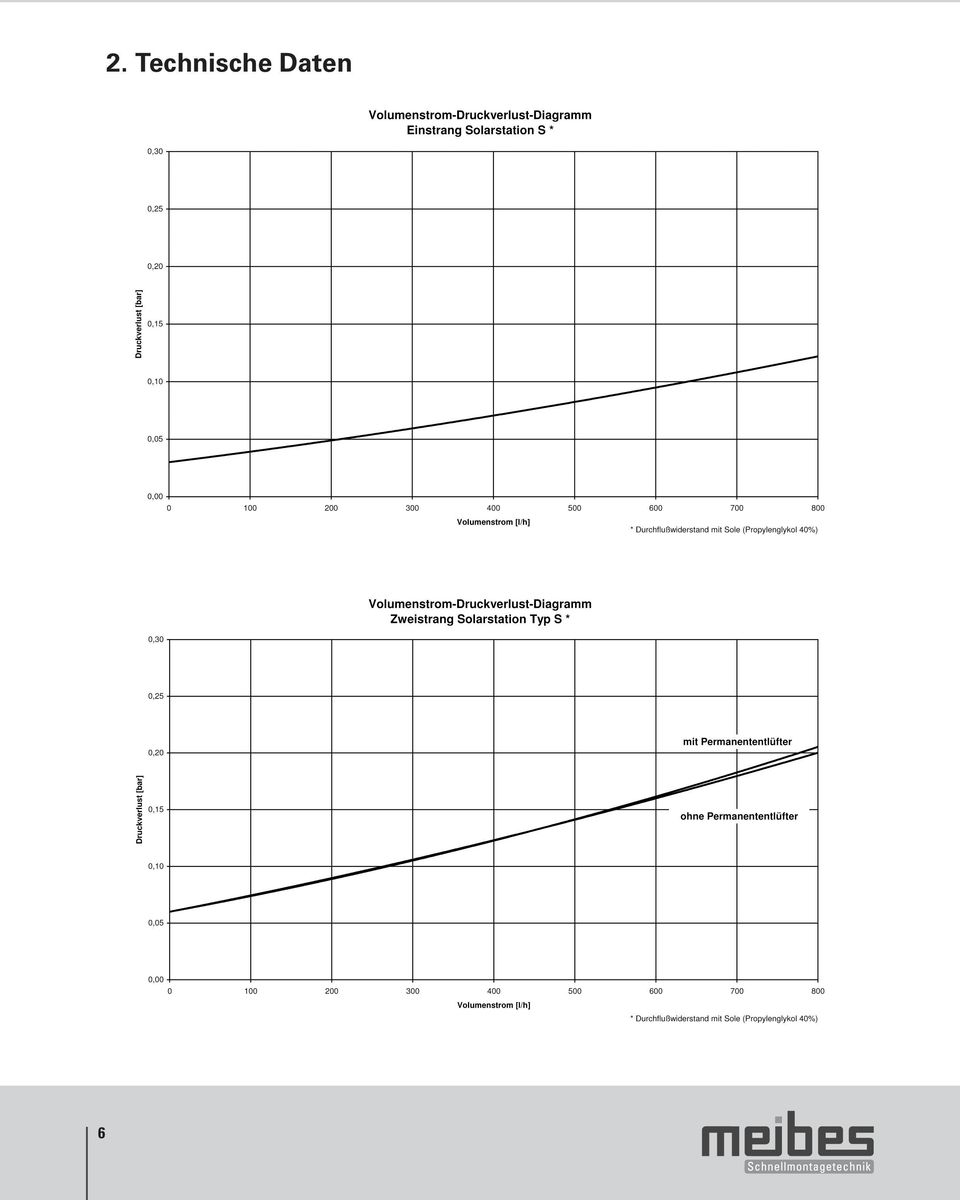
5 2. Technische Daten Die Solarstation S wird als 1- oder 2- Strangausführung vormontiert geliefert. Optional erhältlich mit Solarregler sowie Permanententlüfter. Für den Einsatz in thermischen Solaranlagen bis ca. 12 m 2 Kollektorfläche. (In Abhängigkeit von Typ und vorherrschenden/bestehenden Anlagenparametern) DE 1 Sicherheitsventil im Kleinverteiler integriert 2 Manometer 3 KFE- Hahn mit Kappe und Schlauchtülle 4 Solarumwälzpumpe 5 Kleinverteiler mit Anschluß 3/4 AG für ein Ausdehnungsgefäß (VDI 6002 Blatt 1) Volumenregelorgan und KFE- Hahn 6 Volumenstromanzeiger 7 Absperrkugelhähne 3/4 IG x 1 IG-Überwurfmutter mit integriertem Rückflußverhinderer (handaufstellbar) 8 Thermometer 9 Permanententlüfter mit Hand-Schnell-Entlüfter 10 Blockisolation (Bei 1-Strang-Solarstation nur ein Kugelhahn sowie ein Thermometer. Pos. 9 entfällt.) Anschlüsse Solarkreis 3/4 IG für Ausdehnungsgefäß: 3/4 AG max. zul. Temperatur : +120 C, kurzzeitig C (max. zul. Temp. der Pumpe beachten!) max. zul. Druck 10 bar (Ansprechdruck Sicherheitsventil beachten!) Rückflußverhinderer : 1-Strang: 1 x 300 mmws 1 x 300 mm de ca : 2-Strang: 2 x 300 mmws Volumenstromanzeiger : Kombiskala: Propylenglykol 40 % : 0, ,3 l/min Wasser : l/min Anstelle des Volumenstromanzeigers kann auch eine Meßkapsel zur Leistungs- bzw. Ertragserfassung montiert werden (bauseits anzupassen). Thermometer : Anzeigebereich C Manometer : Anzeigebereich bar Sicherheitsventil : Ansprechdruck 6 bar Abmessungen : Achsabstand : 100 mm Höhe Isolation : 385 mm (1-Strang mit Regelung: 430 mm) Breite gesamt Tiefe Isolation : 300 mm (1-Strang: 200 mm) : 185 mm 5
 Volumenregelorgan und KFE- Hahn 6 Volumenstromanzeiger 7 Absperrkugelhähne 3/4 IG x 1 IG-Überwurfmutter mit")
6 6 2. Technische Daten
7 3. Montage 3.1 Wandmontage Die Montage hat an einer tragfähigen und trocknen Wand zu erfolgen. Der Abstand zu den Kollektoren ist so zu wählen, dass eine Überhitzung der Station und des Ausdehnungsgefäßes ausgeschlossen wird (gegebenenfalls Vorschaltgefäß einsetzen). Gefährdungen durch angrenzende Bauwerkskomponenten, Elektro-, Gas-, Wasser- oder Heizungsrohren sind zu vermeiden. Der freie Zugang zur Station, Sicherheitsarmaturen und den Anschlussleitungen ist sicherzustellen DE 1. Montageort wählen 2. Bohrlöcher mittels Montage- und Befestigungsbügel (A) an der Wand markieren. 3. Bohrlöcher erstellen und Dübel einschlagen 4. Station mit Isolationsunterschale anschrauben 5. Rohrnetzanbindung spannungsfrei herstellen Vor Modulmontage der Einstrang Solarstation die Isolierung entfernen und das Modul aus Halterungsclip heben. Das untere Befestigungsloch (hinter dem Durchflussmesser) ist nach dem Entfernen des Moduls zugänglich. Nach erfolgter Montage der Isolierung muss das Modul zurück in den Halterungsclip. Überprüfen Sie die Festigkeit. 3.2 Absperrarmaturen Hinweis: Absperrarmaturen müssen stets geöffnet und gegen unbeabsichtigtes Schließen gesichert sein. Die Betätigung ist nur von geschulten Fachpersonal vorzunehmen! Für den Betrieb der Anlage müssen die Kugelhähne komplett geöffnet sein (Position 1). Obere Absperrarmaturen Die oberen Absperrarmaturen sind mit integrierten, handaufstellbaren Rückflussverhinderer ausgerüstet. Die Fließrichtung bzw. Stellung ist durch die angefaste Seite ersichtlich (vgl. Abb.). Bei Nichtbeachtung der Fließrichtung kann der Rückflussverhinderer gegen die vorgesehen Fließrichtung wirken und somit den Durchfluss sperren. Betriebszustand mit aktiven Rückflussverhinderern (vgl. Abb.): - Kugelhahn: Solarrücklauf (kalter, Pumpenstrang) nach oben (Stellung 1) - Kugelhahn (Zweistrang): Solarvorlauf (heiß) nach unten 7

8 3. Montage In Stellung 3 (geschlossen) muss zur Sicherstellung der Sicherheitsfunktion des Sicherheitsventils die angefaste Seite der Spindel in Richtung Sicherheitsbaugruppe zeigen. Spindelstellung: 1 Automatik 2 offen (z.b. beim Spülen/Füllen) 3 geschlossen Untere Absperrarmatur Die untere Absperrung ist in dem Kleinverteiler integriert, an dem sich ebenso der Anschluss des Membranausdehnungs-gefäßes sowie ein KFE-Hahn befindet. Die Absperrung arbeitet in der Position 1 bis 2 (vgl. Abb.) auch als Volumenstrombegrenzer. Spindelstellung: 1 geschlossen (Spülen) 2 offen 3 geschlossen (Pumpenwechsel) 8
 3 geschlossen Untere Absperrarmatur Die untere Absperrung ist in dem Kleinverteiler integriert, an dem sich ebenso der Anschluss")
9 3. Montage 3.3 Thermometerwechsel Die Thermometer sind nur eingesteckt und lassen sich einfach durch herausziehen tauschen. Es sollte beachtet werden, dass ein entnommenes Thermometer durch ein gleichartiges ersetzt wird. Bitte auf die farbliche Kennzeichnung achten. (rote Schrift = Vorlauf; blaue Schrift = Rücklauf) DE 3.4 Sicherheitsventil Die Station ist mit einem Sicherheitsventil ausgestattet. Der Betriebsdruck kann an dem Manometer kontrolliert werden. Sicherheitsventile : 3/4 x 1 Ansprechdruck primär : 6 bar Die mitgelieferte Sicherheitsbaugruppe ist an der dafür vorgesehenen Position der Solarstation fest zu montierenen (vgl. Abb.). 3.5 Rückflussverhinderer Die Rückflussverhinderer in der Station verhindern bei Stillstand der Anlage ein unkontrolliertes Zirkulieren der Wärmeträgerflüssigkeit und wirken somit einer Auskühlung des Speichers entgegen. Diese befinden sich im Vor- und Rücklauf. Durch Verstellen des Drehgriffes (Kugelhahn) von der Anschlagsstellung um ca. 45 im Uhrzeigersinn kann es manuell geöffnet werden (vgl. Abs. 3.2). Dieses ist vor allem beim Entleeren der Anlage zu beachten und anzuwenden. Die Markierung der Fließrichtung (Pfeilrichtung) befindet sich auf der Spindel des Kugelhahnes. Die Fließrichtung muss unbedingt beachtet werden (vgl. Abs. 3.2).Öffnungsdruck: je ca. 300 mm Wassersäule. 0 - Kugelhahn offen, Rückflussverhinderer aktiv 45 - Kugelhahn offen und Rückflussverhinderer inaktiv 90 - Kugelhahn geschlossen 9

10 3. Montage 3.6 Anschluss eines Ausdehnungsgefäßes Ausdehnungsgefäße nehmen die Volumenänderungen beim Aufheizen oder Abkühlen der Wärmeträgerflüssigkeit auf und halten eine Flüssigkeitsreserve zum Ausgleich einer geringen Leckagerate vor. Entsprechend den Richtlinien der VDI befindet sich der Anschluß des Membranausdehnungsgefäßes auf der Saugseite, also unterhalb der Pumpe (vgl. Technische Daten). Es sind nur geeignete und richtig ausgelegte Ausdehnungsgefäße (vgl. DIN 4807) zu verwenden. Bei entsprechend vorherrschenden Temperaturen evtl. Vorschaltgefäße verwenden. 3.7 Wärmeträgermedium Verwenden Sie nur geeignete und zugelassene Solarflüssigkeit mit Frostschutzmittel (vgl. DIN 4757), die für Solaranlagen geeignet ist! Notieren Sie sich Hersteller und Typ, da diese unter Umständen nicht mit Mitteln anderer Hersteller gemischt werden dürfen. 4. Druckprobe, Befüllen und Spülen der Anlage 4.1 Druckprobe Anschlüsse, Bauteile und Verbindungen auf Dichtheit kontrollieren. Bei Undichtheiten Anlage entleeren, nachbessern und Druckprobe wiederholen. 10
 zu verwenden. Bei entsprechend vorherrschenden Temperaturen evtl. Vorschaltgefäße verwenden. 3.")
11 4. Druckprobe, Befüllen und Spülen der Anlage 4.2 Spülen und Befüllen Ein sorgfältiges bzw. bedarfsgerechtes Spülen der Anlage ist durchzuführen. Es müssen vor Inbetriebnahme alle Schmutz- und Luftpartikel aus der Anlage entfernt werden. Wird Wasser zum Spülen verwendet, ist die Anlage bei möglicher Frostgefahr am Aufstellungsort komplett zu Entleeren und sofort mit geeigneter und zugelassener Solarflüssigkeit mit Frostschutzmittel zu ersetzen. DE Achtung: obere Absperrungen : offen (Stellung 2) untere Absperrung : Spülstellung (Stellung 1) Es ist zu beachten, dass die untere Absperrung am Volumenstrommesser beim Befüllen auf die Position 1 (vgl. Abs. 3.2.) gestellt wird und die Kugelhähne auf 45 (Position 2) gestellt werden. Durch diese Position werden die Rückflussverhinderer geöffnet. Nach Beendigung die untere und obere Absperrung öffnen (vgl. Abs. 3.2.)! Achtung (vgl. Abs. 3.2.): obere Absperrungen : Automatik (Position 1) untere Absperrung : offen (Position 2) 4.3 Entlüften Unsachgemäßes Entlüften führt zu Druckabfall und kann zu Störungen in der Solaranlage führen. Die Temperaturen der ausweichenden Luft und des Wärmeträgermediums können größer 60 C sein, damit besteht erhöhte Verbrühungsgefahr. Der Entlüfter sitzt am höchsten Punkt der Anlage. Nach dem sorgfältigen und fachgerechten Entlüften ist der Anlagendruck jeweils wieder auf den Betriebsdruck zu erhöhen! Im Betriebszustand am Permanententlüfter (Option) gelegentlich entlüften. 11

12 4. Druckprobe, Befüllen und Spülen der Anlage 4.4 Entleeren Beim Entleeren der Anlage muss beachtet werden, dass die Griffe der Kugelhähne auf 45 (vgl. Abs. 3.2.) gestellt werden, bevor die Anlage am tiefsten Punkt entleert wird. In dieser Position sind die Rückflussverhinderer max. geöffnet. Auf vollständige Entleerung des Rohrleitungssystems achten. Die Wärmeträgerflüssigkeit sollte mit einem geeignetem Auffangbehälter aufgefangen und gemäß der Herstellerangaben umweltgerecht entsorgt werden. Hinweis: Anlage steht in der Regel unter Druck! Verbrühungsgefahr! 5. Ausführungen Die Preise entnehmen sie bitte der aktuellen Preisliste. 1 Strang Ausführung Art N ohne Pumpe EA mit Grundfos Solar mit Grundfos Solar PWM Signal mit Wilo Star-ST 15/ WI mit Wilo Stratos PARA 15/ V Signal WI mit Wilo Stratos PARAPara 15/1-7 - PWM Signal WI Wie zuvor jedoch mit integrierter Regelung Basic Pro Digitaler Temperaturdifferenzregler für thermische Solaranlagen (1 Kollektorfeld, 1 Speicher); Vollgrafisches hintergrundbeleuchtetes schwarz/weiß-display, Bedienung über Dreh-/Drücksteller und ESC-Taste; 3 Eingänge für PT 1000 Fühler, Analog- bzw. PWM-Ausgang für Hocheffizienzpumpe, Drehzahlregelung, ein vorkonfiguriertes Hydraulikschema, Triac Ausgang, Fehlerüberwachung, Handbetriebsmöglichkeit, Kollektorschutzfunktion, Rückkühlfunktion; Inbetriebnahme-/Service-Assistent, Fest-T- und Delta-T-Regelung, Röhrenkollektorfunktion, Nachlaufzeit für Ausgänge, Frostschutz, Sensor-Überwachung, Überwachung Ausgangsparameter, Betriebsstundenzähler für Ausgänge, Solarertragsmessung für Pumpenansteuerung inkl. Datenausgabe, Ertragserfassung ohne Volumenstrommessung möglich, Lieferumfang inklusive 2 Universaltemperaturfühler PT 1000 Ausführung Art N ohne Pumpe EA mit Grungfos-Pumpe Solar mit Grungfos-Pumpe Solar PWM Signal mit Wilo-Pumpe Star-ST 15/ WI mit Wilo-Pumpe Stratos-Para 15/ V Signal WI mit Wilo Stratos-Para 15/1-7 - PWM Signal WI Die Einbau- und Montagehinweise der Pumpenhersteller sind zu beachten. Zubehör für den Anschluss eines Vorschaltgefäßes oder die Verbindung von 2 Solarstationen, z.b. für Ost-West-Verschraubung finden Sie in der aktuellen Preisliste. 12

13 5. Ausführungen Die Preise entnehmen Sie bitt die aktuelle Preisliste. 2 Strang Version ohne Regelung ohne Permanententlüfter ohne Pumpe EA mit Grundfos-Pumpe Solar mit Grundfos-Pumpe Solar PWM Signal mit Wilo-Pumpe Star-ST 15/ WI mit Wilo-Pumpe Stratos-Para 15/ V Signal WI mit Wilo-Pumpe Stratos-Para 15/1-7 - PWM Signal WI DE ohne Regelung mit Permanententlüfter ohne Pumpe EA mit Grundfos-Pumpe Solar mit Grundfos-Pumpe Solar PWM Signal mit Wilo-Pumpe Star-ST 15/ WI mit Wilo-Pumpe Stratos-Para 15/ V Signal mit Wilo-Pumpe Stratos-Para 15/1-7 - PWM Signal WI WI mit Solarregelung Basic Pro ohne Permanententlüfter ohne Pumpe EA mit Grundfos-Pumpe Solar mit Grundfos-Pumpe Solar PWM Signal mit Wilo-Pumpe Star-ST 15/ WI mit Wilo-Pumpe Stratos-Para 15/ V Signal WI mit Wilo-Pumpe Stratos-Para 15/1-7 - PWM Signal WI mit Solarregelung Basic Pro ohne Permanententlüfter ohne Pumpe EA mit Grundfos-Pumpe Solar mit Grungdfos-Pumpe Solar PWM Signal mit Wilo-Pumpe Star-ST 15/ WI mit Wilo-Pumpe Stratos-Para 15/ V Signal WI mit Wilo-Pumpe Stratos-Para 15/1-7 - PWM Signal WI Die Einbau- und Montagehinweise der Pumpenhersteller sind zu beachten. 13

14 Table of contents 1 Safety notes Regulations/Guidelines Intended use Initial start-up Working on the system Liability 16 2 Technical Data 17 3 Installation Wall-mounted installation Shut-off fittings Changing thermometers Safety valve Backflow preventer Connecting an expansion vessel (provided on site) Heat transfer medium 22 4 Pressure Test, Filling and Flushing the System 4.1 Leak test Flushing and filling Venting Draining 24 5 Versions 24 Solar circuit control Please note: The installation and operating instructions for the controller model are enclosed separately. 14

15 1. Safety notes Read through these instructions carefully before installation. The complete station may be installed and initially started up by an approved, qualified firm only. Familiarise yourself with all the parts and their handling before starting the work. - Read the assembly instructions before use - Risk of increased temperature - Risk of cutting - Risk of electrical voltage - Risk of crushing - Risk of dropping during assembly GB 1.1 Safety notes Note and observe the accident prevention regulations/health & safety regulations, the environmental regulations and the statutory regulations for assembly, installation and operation. Furthermore, the relevant guidelines of the DIN, EN, DVGW, VDI and VDE (incl. lightning protection) as well as all relevant country-specific standards, laws and guidelines. Electrical connection: Electrical connection work may only be carried out by qualified electricians. The VDE guidelines and regulations of the electrical utility company responsible must all be complied with. Extract: Thermal solar systems and their components: DIN EN Solar collectors DIN EN Prefabricated systems DIN EN Custom built systems Electrical connection: VDE 0100: Construction of electrical equipment, earthing, protective conductors, equipotential conductors. VDE 0185: General information for the installation of lightning protection systems. VDE 0190: Main equipotential bonding of electrical systems. Additional guidelines and notes: VDI 6002 Part 1 General principles, systems engineering and use in housing VDI 6002 Part 2 Uses in student hostels, retirement homes, hospitals, indoor swimming pools and on camping sites 15

16 1. Safety notes 1.2 Intended use The described station is intended for primary operation of the solar substation with propylene glycol - water mixtures. Use of other media is not allowed. Media temperature > 60 C(Risk of scalding) Setpoint and filling pressure < pickup pressure of the safety fitting All shut-off fittings may be closed in the service case only and only if the collectors are covered as otherwise the safety fittings lose their effect. Caution: Do not make any changes to electrical components, the design or the hydraulic components! Otherwise you will impair the safe function of the system. 1.3 Initial commissioning Before the initial commissioning, the system must be checked for any leakage as well as to make sure the hydraulic linkage is correct and that the electrical connection work has been carried out with care and correctly. The system must also be carefully flushed in accordance with DIN The initial commissioning must be carried out by a trained specialist and a written record of it must be drawn up. In addition to this, the settings must also recorded in writing. The technical documentation must remain with equipment Working on the system The system must be disconnected from the power supply and checked to ensure it is safely isolated from the power supply (e.g. at the separate fuse or a master switch). Secure the system against being switched back on again. IMPORTANT: Risk of scalding: Media temperature > 60 C 1.5 Liability We reserve all copyrights to this document. These installation and operating instructions must be handed over to the customer. The skilled trades carrying out the work (e.g. fitter) must explain to the customer how the equipment works and how to operate it in a way they can understand. 16

17 2. Technical Data The solar station S is supplied pre-assembled as a 1 or 2 branch type.optionally available with solar controller as well aspermanent venter. For use in thermal solar collector systems with collector areas of up to approx 12 m 2 (Depending on model and prevailing/existing system parameters) 1 Safety valve integrated in small distributor 2 Pressure gauge 3 KFE tap with cap and hose connection nozzle 4 Solar circulation pump 5 Small distributor with 3/4 AG (outer thread) connection for an expansion vessel (VDI 6002 Part 1) volumetric control device and KFE tap 6 Volumetric flow indicator 7 Shut-off ball valves 3/4 IG (internal thread) x 1 IG (internal thread) union nut with integrated backflow preventer (manually openable) 8 Thermometer 9 Permanent venter with quick manual venter 10 Block insulation GB (One ball valve only in 1 branch solar station as well as one thermometer Item 9 omitted.) Connections Solar circuit 3/4 IG (internal thread) for expansion vessel 3/4 AG (external thread) max. zul. Temperatur : +120 C, kurzzeitig C (max. zul. Temp. der Pumpe beachten!) max allowable pressure 10 bar (note pick-up pressure of safety valve!) Backflow preventer : 1 branch: 1 x 300 mmws 1 x 300 mm : 2 branch: 2 x 300 mmws Volumetric flow indicator : Combination scale: Propylenglykol 40 % : 0, ,3 l/min Water: l/min A measuring capsule can be installed for recording the output or yield Thermometer (to be adjusted on site) instead of the volumetric flow indicator. Pressure gauge : Display range bar Safety valve : Display range 6 bar Dimensions : Achsabstand : 100 mm Height of insulation : 385 mm (1 branch with control: 430 mm) Total width Depth of insulation : 300 mm (1 branch: 200 mm) : 185 mm 17
 x 1 IG (internal thread) union nut with integrated backflow preventer (manually openable) 8")
18 Volumetric flow - pressure loss diagram Single branch solar station Type S Pressure loss (bar) Volumetric flow l/h Volumetric flow - pressure loss diagram Two-branch solar station Type S with permanent permanent catcher Pressure loss (bar) without permanent permanent catcher Volumetric flow l/h 18
 without permanent permanent catcher Volumetric flow")
19 3. Installation 3.1 Wall-mounted installation The system must be installed on a firm, load-bearing and dry wall. The distance to the collectors must be chosen to prevent overheating of the station. Risks due to adjacent structural components, electrical cables, gas, water or heating pipes must be avoided. Ensure free access to the station, safety fittings and connection pipes and cables. 1. Choose installation site 2. Mark drillholes on the wall by means of installation and fixing bracket (A). 3. Make drillholes and knock in anchors/rawl plugs 4. Screw on station with insulation subsection 5. Pipeline binding without tension manufacture GB Before assembling the modules of the single-line solar station, remove the insulation and lift the module from the retainer clip. The lower mounting hole (behind the flow meter) is accessible after removing the module. Once the insulation has been installed, put the module back into the retainer clip. Check if it is attached firmly. 3.2 Shut-off fittings Top shut-off fittings The top shut-off fittings are equipped with integrated, manually openable backflow preventer. The direction of flow is indicated by a stylised arrow shape on the spindle.). Upper shut-off fittings The upper shut-off fittings are fitted with integrated, manually adjustable backflow preventers. The flow direction or position is visible through the bevelled side (see fig. ). If the flow direction is not observed, the back flow preventer can act against the intended flow direction and thus block the flow. Operating state with active backflow preventers (see. fig.): - Ball valve: Solar return (cold, solar pump line) upwards (Position 1) - Ball valve (two-line): Solar flow (hot) downwards 19

20 3. Installation Spindle position: 1 Automatic 2 open (e.g. for flushing/filling) 3 closed In Position 3 (closed) the tip of the spindle must be pointed in the direction of the safety module to ensure the safety function of the safety valve. - Ball valve: Solar return (cold, pump branch) arrow facing upwards. - Ball valve: Solar flow (hot) downwards Bottom shut-off fitting The bottom shut-off is integrated in a small distributor which also includes the connection for a diaphragm expansion vessel and a drain valve. The shut-off also functions as a volumetric flow limiter in Position 1 to 2 (cf. Fig.). forward flow return flow Spindle position: 1 closed 2 open 3 closed (flushing/pump change) Volume flow meter reading edge upwards 20
 downwards Bottom shut-off fitting The bottom shut-off is integrated in a small distributor which also includes the connection for a diaphragm expansion")
21 3. Installation 3.3 Changing thermometers The thermometers are just inserted and can be replaced simply by pulling them out. Be sure to replace a thermometer taken out by one of the same type. Mind the colour identification. (Red lettering = forward flow; blue lettering = return flow) 3.4 Safety valve GB The station is equipped with a safety valve. The operating pressure can be checked on the pressure gauge. Safety valves : 3/4 x 1 Primarily triggering pressure : 6 bar Firmly mount the safety subassembly that comes with the unit at solar station s position intended for it. 3.5 Backflow preventer The backflow preventer in the station prevent uncontrolled circulation of the medium when the system stops, thus counteracting any cooling down of the storage tank. These are located in the foreword flow and return flow. The non-return valve in the foreword flow (see Fig. 10) can be manually opened (see Fig. 8) by turning the handle to the right by approx 45 (see Fig. 9) from the end of position. Bear this in mind and use it especially when draining the system. Cracking pressure: ever approx. 300 mm water column 0 - Ball valve open, non-return valve in operation 45 - Ball valve and non-return valve open 90 - Ball valve closed 21
22 3. Installation 3.6 Connecting an expansion vessel (provided on site) Expansion vessels absorb the volumetric changes during heating or cooling of the liquid and provide a liquid reserve to compensate for minor leakages. In accordance with the VDI guidelines, the connection of the diaphragm expansion vessel is on the inlet side (suction side), i.e. underneath the pump (cf. Technical Data). Suitable, correctly designed expansion vessels only are to be used (cf. DIN 4807). Use backup vessels if necessary depending on the predominant temperatures. Expansion tank connection 3.7 Heat transfer medium Use brine solutions only with antifreeze suitable for solar systems! Note the manufacturer and type, as these may possibly not be allowed to be mixed with other manufacturers media. The following work may be carried out by trained qualified personnel only. When performing the pressure test (leak test), filling and flushing the system, ensure that all shut-off fittings are open. The collectors must be covered. Do not undertake any switching procedures to relieve pressure using the shut-off fitting. 4. Pressure Test, Filling and Flushing the System 4.1 Leak test Check the connections, components and connections for leaks. If there are any leaks, drain and repair the system and repeat the leak test. 22
23 4. Pressure Test, Filling and Flushing the System 4.2 Flushing and filling Carry out a flush of the system suited for the requirements, doing so in accordance. Before commissioning, all particles of soiling and air have to be removed from the system. If water is used for flushing, if there is a danger of freezing, the system must be completely drained or immediately replaced with antifreeze agent. Bear in mind that the lower shut-off on the volume flow meter has to be closed during filling, and the ball valve handle in the forward flow set to 45 C. This position will result in the non-return valve being opened. The collectors have to be covered to prevent injuries and/or damage. Important: - top shut-off devices : open (Position 2) - bottom shut-off device : open (Position 1) GB It is important to ensure that the lower shut-off on the volumetric flow meter is set to Position 1 during filling (see section 3.2.) and the ball valves to 45 (Position 2). This position opens the backflow preventer. When the process is complete, open the lower and upper shut-off (see section 3.2.)! Warning (see section 3.2.): Upper shut-off : Automatic (Position 1) Lower shut-off : open (position 2) 4.3 Venting Improper venting causes a pressure drop and can result in malfunctions in the solar system. The temperature of the escaping air and heat transfer medium can be higher than 60 C; therefore there is an increased risk of scalding. The vent is located at the highest point in the system. After venting, increase the system pressure back to the operating pressure!vent occasionally at permanent venter (optional) in operating condition. Permanent vent optional 23
24 4. Pressure Test, Filling and Flushing the System 4.4 Entleeren When draining the system, be sure the handle of the forward flow ball valve is set to 45 before the forward flow side is drained at the lowest point. In this position, the non-return valve is open. The return flow side has to be drained both at the lowest point in the pipework circulation system and at the safty set with the drain valve. When water is used, be sure the pipeline system is completely drained. The heat transfer fluid should be collected in a suitable container and disposed of according to the manufacturer s instructions in an environmentally sound manner. Note: The system is usually under pressure. Danger of scalding! 5. Versions Please refer to the current price list for prices. 1 - branch Type: Art N without pump EA with Grundfos Solar with Grundfos Solar PWM signal with Wilo Star-ST 15/ WI with Wilo Stratos-PARA 15/ V signal WI with Wilo Stratos-PARA 15/1-7 - PWM signal WI As above but with integrated Basic Pro controller Digital differential temperature controller for thermal solar systems (1x collector array, 1x accumulator); full graphic backlit black/white display, operation via rotary/push control and ESC-button; 3 inputs for PT 1000 sensor, analog or PWM output for high-efficiency pump, speed regulation, pre-configured hydraulics diagram, Triac output, error monitoring, manual operation option, collector safety function, recool function, start-up/service assistant, fixed T and Delta T regulation, tube collector function, shut-off delay for outputs, antifreeze, sensor monitoring, monitoring of output parameters, operating hours counter for outputs, solar yield measurement for pump control including data output, yield recording without volumetric flow meter option, scope of delivery including 2x PT 1000 universal temperature sensors Type: Art N without pump EA with Grundfos-pump Solar with Grundfos pump Solar PWM Signal with Wilo-pump Star-ST 15/ WI with Wilo-pump Stratos-Para 15/ WI with Wilo Stratos-Para 15/1-7 - PWM Signal WI The pump manufacturer s installation and assembly instructions must be observed. Accessories for connecting an auxiliary vessel or 2 solar stations, e.g., for east-west installations, are available in the current price list. 24
25 5. Versions Please refer to the current price list for prices. 2 - branch without controller, without permanent venter without pump EA with Grundfos-pump Solar with Grundfos-pump Solar PWM Signal with Wilo-pump Star-ST 15/ WI with Wilo-pump Stratos-Para 15/ V Signal WI with Wilo-pump Stratos-Para 15/1-7 - PWM Signal WI without controller, without permanent venter without pump EA with Grundfos-pump Solar with Grundfos-pump Solar PWM Signal with Wilo-pump Star-ST 15/ WI with Wilo-pump Stratos-Para 15/ V Signal with Wilo-pump Stratos-Para 15/1-7 - PWM Signal WI WI GB with controller Basic Pro without permanent venter without pump EA with Grundfos-pump Solar with Grundfos-pump Solar PWM Signal with Wilo-pump Star-ST 15/ WI with Wilo-pump Stratos-Para 15/ V Signal WI with Wilo-pump Stratos-Para 15/1-7 - PWM Signal WI with controller Basic Pro without permanent venter without pump EA with Grundfos-pump Solar with Grundfos-pump Solar PWM Signal with Wilo-pump Star-ST 15/ WI with Wilo-pump Stratos-Para 15/ V Signal WI with Wilo-pump Stratos-Para 15/1-7 - PWM Signal WI The pump manufacturers installation and assembly instructions must be noted and observed. 25
26 Table des matières 1 Consignes de sécurité Règlements/directives Utilisation conforme aux prescriptions Première mise en service Travaux sur l installation Responsabilité 28 2 Caractéristiques techniques 29 3 Montage Montage mural Vannes d arrêt Echange du thermomètre Soupape de sécurité Clapet anti-retour Raccordement d un vase d expansion (fourni par le client) Agent caloporteur 34 4 Evacuation, remplissage et purge de l installation Essai de pression Purge et remplissage Purge d air Vidange 36 5 Déclarations 36 Système de commande du circuit solaire A respecter : La notice de montage et de fonctionnement du type de commande est jointe séparément. 26
27 1. Consignes de sécurité Merci de lire attentivement le présent mode d emploi avant le montage. Le montage et la première mise en service de la station intégrale doivent être effectués par une société spécialisée et agrée. Avant de commencer le travail, familiarisez-vous bien avec le fonctionnement de toutes les pièces. - Avant l utilisation, lire les instructions de montage - Risque de haute température - Risque de se couper - Danger dû à la tension électrique - Risque de se couper - Risque de tomber lors du montage 1.1 Règlements/directives Respectez les règlements en vigueur relevant de la prévention des accidents, de la protection de l environnement et les règlements législatifs concernant le montage, l installation et le fonctionnement. Par ailleurs, respectez également les directives correspondantes et conformes aux normes DIN, EN, DVGW, VDI et VDE (protection contre la foudre inclue) ainsi que toutes les normes, lois et directives en vigueur dans haque pays. Raccordements électriques : Les travaux de raccordements électriques doivent être effectués uniquement par un électricien agrée. Les directives de l Association de l électrotechnique, de l électronique et de la technique d information (Verband der Elektrotechnik, Elektronik und Informationstechnik «VDE») et les prescriptions du distributeur d énergie compétent sont à respecter. FR Extrait : Installations solaires thermiques et leurs éléments de construction : DIN EN Collecteurs de soleil DIN EN Installations préfabriquées DIN EN Installations fabriquées sur mesure Raccordements électriques : VDE 0100: mise en service de matériaux électriques, mise à la terre, conducteurs de protection, con ducteurs d équipotentialité. VDE 0185: généralités concernant la mise en service d installations de protection contre la foudre. VDE 0190: conducteur principal d équipotentialité sur des installations électriques. Consignes et directives supplémentaires : VDI 6002 Feuille 1 Généralités de base, génie des systèmes techniques et utilisation dans le bâtiment VDI 6002 Feuille 2 Utilisation dans les foyers d étudiants, résidences pour personne du troisième âge, hôpitaux, piscines couvertes et campings. 27
28 1. Consignes de sécurité 1.2 Utilisation conforme aux prescriptions La station décrite est prévue pour le fonctionnement primaire de la station de transmission solaire avec un mélange à base de propylène glycol et eau. L utilisation d un autre agent n est pas autorisée. Température de l agent > 60 C (danger d échaudement) Pression de consigne ou < pression de démarrage de la de remplissage vanne de sécurité Les vannes d arrêt ne doivent être fermées qu en cas de nécessité et avec les capteurs recouverts, sinon elles perdraient de leur effet. Attention : N effectuez aucune transformation des composants électriques, de la construction en elle-même ou des composants hydrauliques! Sinon vous compromettez le bon fonctionnement de l installation. 1.3 Initial commissioning Avant la première mise en service, il faut vérifier l étanchéité de l installation, le bon branchement des raccords hydrauliques et un travail de raccordement électrique correct. De plus, il faut effectuer une purge minutieuse de l installation conformément à la norme DIN La première mise en service doit être effectuée par du personnel formé et spécialisé et un compte-rendu doit être fait par écrit. Par ailleurs, les valeurs d ajustement sont à noter. La documentation technique doit toujours se trouver à proximité de l appareil. 1.4 Travaux sur l installation L installation doit être mise hors tension, celle-ci devant être contrôlée (par exemple sur les fusibles séparés ou sur le commutateur principal). L installation doit être protégée contre toute nouvelle mise en circuit. ATTENTION: Danger d échaudement: Température de l agent > 60 C 1.5 Responsabilité Nous nous réservons les droits d auteurs pour le présent document. Le mode d emploi du montage et de l utilisation doit être remis au client. Le personnel qualifié (par exemple l installateur) doit instruire le client de manière compréhensive de l utilisation correcte et des effets de l appareil. 28
29 2. Caractéristiques techniques La station solaire est livrée en unité préfabriquée avec 1 ou 2 lignes.régleur solaire et ventilateur permanent en option. Pour une utilisation dans les installations solaires thermiques ayant une surface de récupération allant jusqu à env. 12 m 2. (Dépendant du type et des paramètres de l installation prédominants/préexistants) 1 Soupape de sécurité intégrée dans le distributeur 2 Manomètre 3 Robinet KFE avec bouchon et raccord de tuyau 4 Pompe de circulation solaire 5 Distributeur avec raccord 3/4 AG pour un vase d expansion (VDI 6002 Feuille 1) Organe de réglage de volume et robinet KFE 6 Indicateur du débit volumique 7 Robinets d arrêt à boisseau sphérique, écrou raccord IG 3/4 IG x 1 avec freins à clapet anti-retour intégrés (réglage manuel) 8 Thermomètre 9 Dispositif d aération permanente avec ventilation rapide à régler manuellement 10 Bloc isolant (Pour les stations solaires à 1 ligne seulement, 1 robinet à boisseau sphérique et 1 thermomètre sont prévus. Pos. 9 supprimée) FR Raccordements Circuit solaire 3/4 IG (internal thread) pour vase d expansion 3/4 AG (external thread) Température max. admise : +120 C, momentanément C (attention à la température max. admise de la pompe!) Pression max. admise 10 bars (attention à la pression de démarrage de la soupape de sécurité!) Clapet anti-retour : 1 ligne: 1 x 300 mmws : 2 lignes : 2 x 300 mmws Indicateur de débit volumique : Echelle mixte : propylène glycol 40 % : 0, ,3 l/min eau : l/min Il est possible de monter un godet gradué pour mesurer la puissance et le rendement à la Thermomètre place de l indicateur du débit volumique (à faire adapter par le client). Plage d affichage C Manometer Soupape de sécurité :Plage d affichage bar : Pression de démarrage 6 bar Dimensions : Entraxe : 100 mm Hauteur Isolation : 385 mm (1 ligne avec commande : 430 mm) Largeur totale : 300 mm (1 ligne: 200 mm) Profondeur Isolation : 185 mm 29
30 Diagramme de débit volumique et de perte de pression Station solaire à 1 ligne, type S Perte de pression [bar] Débit volumique [l/h] Diagramme de débit volumique et de perte de pression Station solaire à 2 lignes, type S avec purgeur permanent Perte de pression [bar] sans purgeur permanent Débit volumique [l/h] 30
31 3. Montage 3.1 Montage mural Le montage doit être effectué sur un mur sec et résistant. L écart jusqu aux collecteurs est déterminé de façon à exclure une surchauffe de la station. Empêcher tout danger lié aux composants d ouvrage, aux tuyauteries de gaz, d eau ou de chauffage et aux câbles électriques adjacents. Assurer le libre accès à la station, aux robinetteries de sécurité et aux conduites de raccordement. 1. Choisir le lieu de montage 2. Marquer les trous de perçage sur le mur à l aide des étriers de montage et de fixation (A). 3. Percer les trous et enfoncer les chevilles 4. Fixer la station avec le support de plateau isolant 5. Un lien de canalisation fabriquer sans tension Avant le montage du module de la station solaire à une voie, retirer l isolation et soulever le module hors du clip de fixation. Le trou de fixation du bas (derrière le débitmètre) est accessible une fois le module retiré. Lorsque l isolation est montée, le module doit être replacé dans le clip de fixation. Vérifiez la fixation. 3.2 Vanne d arrêt FR Vannes d arrêt supérieures Les vannes d arrêt supérieures sont équipées de freins à Clapet anti-retour intégrés et à régler manuellement. Le sens d écoulement est marqué par une flèche sur le vérin. Robinets d arrêt supérieurs Les robinets d arrêt supérieurs sont équipés de clapets anti-retour intégrés, pouvant être positionnés manuellement. Le sens d écoulement et la position sont visibles du côté fraisé (voir fig.). Si le sens d écoulement n est pas respecté, le clapet anti-retour peut agir contre le sens d écoulement prévu et bloquer ainsi le débit. État de fonctionnement avec clapets anti-retour actifs (voir fig.) : - Robinet : retour solaire (voie de la pompe, froide) vers le haut (position 1) - Robinet (deux voies) : arrivée solaire (chaud) vers le bas 31
32 3. Montage Position du vérin: 1 Automatique 2 Ouvert (par exemple pour purge/remplissage) 3 Fermé Dans la position 3 (fermé), la pointe du vérin doit pointer vers le bloc de composants de sécurité pour assurer la fonction de sécurité de la soupape de sécurité. - Robinet à boisseau sphérique : retour solaire (froid, ligne de pompe) flèche vers le haut. - Robinet à boisseau sphérique : départ solaire Vanne d arrêt inférieure La vanne d arrêt inferieure est intégrée dans un micro distributeur comprenant également le raccord pour le vase d expansion à membrane et un robinet KFE. La vanne sert aussi comme limiteur de débit dans la position 1 à 2 (voir fig.). Retour Départ Position du vérin : 1 fermé 2 ouvert 3 fermé (purge /changement de pompe) Corps volumétrique arête de lecture en haut 32
33 3. Montage 3.3 Echange du thermomètre Les thermomètres ne sont pas fixés et peuvent être échangés en les retirant. Il faut cependant tenir compte qu un thermomètre retiré doit être remplacé uniquement par un thermomètre similaire. Veiller au marquage de couleur. (Écriture rouge = Retour, écriture bleue =Départ.) 3.4 Soupape de sécurité La station est équipée d une soupape de sécurité. La pression en service peut être contrôlée au manomètre. Soupapes de sécurité : 3/4 x 1 Pression de démarrage circuit primaire : 6 bars Monter le groupe de sécurité livré à la position prévue à cet FR 3.5 Clapet anti-retour The backflow preventer in the station prevent uncontrolled circulation of the medium when the system stops, thus counteracting any cooling down of the storage tank. These are located in the foreword flow and return flow. The non-return valve in the foreword flow (see Fig. 10) can be manually opened (see Fig. 8) by turning the handle to the right by approx 45 (see Fig. 9) from the end of position. Bear this in mind and use it especially when draining the system. Cracking pressure: ever approx. 300 mm water column 0 - Ball valve open, non-return valve in operation 45 - Ball valve and non-return valve open 90 - Ball valve closed 33
34 3. Installation 3.6 Raccordement d un vase d expansion Les vases d expansion captent les changements de volumes lors de l échauffement ou du refroidissement du liquide et conservent une réserve de liquide pour compenser de petites fuites potentielles Conformément aux directives VDI, le raccord du vase d expansion à membrane se trouve du côté aspiration, c est-à-dire sous la pompe (voir Caractéristiques techniques). Utiliser uniquement des vases d expansion appropriés et montés correctement (voir DIN 4807). Utiliser éventuellement les appareils insérés en amont en fonction des températures prédominantes. Raccord de la cuve d expansion 3.7 Agent caloporteur Utiliser uniquement de la saumure avec un produit antigel convenant aux installations solaires! Notez le type et le fabricant, car en certain cas le mélange mentionné ne devra pas être combiné avec le produit d un autre fabricant. Les travaux suivants doivent être effectués uniquement par du personnel qualifié. Ouvrir toutes les vannes d arrêt lors de l essai de pression, du remplissage et de la purge de l installation. Les collecteurs doivent être recouverts. Ne pas effectuer de changements de rapport pour la détente de la pression sur les dispositifs dotés de vannes d arrêt. 4. Essai de pression, de remplissage et purge de l installation 4.1 Essai de pression Vérifier l étanchéité des branchements, composants et raccordements. En cas de fuites, vider l installation, effectuer les réparations et recommencer l essai de pression. 34
35 4. Essai de pression, de remplissage et purge de l installation 4.2 Flushing and filling Effectuer la purge de l installation conformément. Avant la mise en service, toutes les particules d air et d impureté doivent être éliminées de l installation. En cas de gel et si l on utilise de l eau pour le rinçage, il faut entièrement vider l installation ou la remplir aussitôt d antigel. Il faut veiller à ce que la vanne d arrêt inférieure sur l indicateur de débit volumétrique lors du remplissage dit être fermé et la poignée du robinet doit être réglée au départ à 45. Le clapet anti-retour est ouvert par cette position. Les collecteurs doivent être recouverts afin d éviter les blessures et les détériorations! Attention: - Vannes d arrêt supérieures : ouvert (position 2) - Vanne d arrêt inférieure : ouvert (Position 1) It is important to ensure that the lower shut-off on the volumetric flow meter is set to Position 1 during filling (see section 3.2.) and the ball valves to 45 (Position 2). This position opens the backflow preventer. When the process is complete, open the lower and upper shut-off (see section 3.2.)! FR Warning (see section 3.2.): Upper shut-off : Automatic (Position 1) Lower shut-off : open (position 2) 4.3 Purge d air Une purge d air incorrecte entraîne une chute de pression et peut provoquer des perturbations dans l installation solaire. Les températures de l air sortant et de l agent caloporteur peuvent atteindre plus de 60 C, ce qui présente un danger élevé d échaudement. Le dispositif de désaération est situé au point culminant de l installation. Après la purge d air, il faut de nouveau augmenter la pression de l installation au niveau de la pression de service! En état de marche, purger de temps en temps le dispositif d aération permanente (en option). Ventilateur permanent option 35
36 4. Essai de pression, de remplissage et purge de l installation 4.4 Vidange Lors de la vidange de l installation, il faut veiller à ce que la poignée du robinet de départ soit réglé à 45 avant que la partie de départ soit vidangée au plus bas niveau. Dans cette position, le clapet anti-retour est ouvert. Le côté retour doit être vidangé à son niveau le plus bas du circuit de tuyauterie et d autre part sur le robinet vidange-remplissage du dispositif de sécurité. En cas d utilisation d eau, il faut veiller à une vidange complète du système de tuyauterie. Il est conseillé de collecter le liquide caloporteur dans un récipient approprié et, si besoin, de l éliminer en respectant les réglementations écologiques en vigueur. Remarque: l installation est en général sous pression! Risque de brûlures! Modèle N d art. Sans pompe EA Avec Grundfos Solar Avec Grundfos Solar signal MID Avec Wilo Star-ST 15/ WI Avec Wilo Stratos-Para 15/ V signal WI Avec Wilo Stratos-Para 15/1-7 - signal MID WI 5. Déclarations Merci de consulter la liste des prix pour prendre connaissance de nos nouveaux tarifs 1 - lignes Comme auparavant mais avec régulation Basic Pro intégrée Régulateur différentiel numérique pour installations solaires thermiques (1 champ de collecteur, 1 accumulateur) ; écran noir et blanc entièrement graphique, rétroéclairé, utilisation à l aide de boutons-poussoirs, de boutons rotatifs et de la touche Echap ; 3 entrées pour capteur PT 1000, sortie analogique ou PWM pour pompe à haut rendement, régulation de la vitesse, schéma hydraulique préconfiguré, sortie Triac, surveillance des erreurs, possibilité de commande manuelle, fonction de protection des collecteurs, fonction de réfrigération de retour ; assistant de mise en service/d entretien, régulation en T fixe et T delta, fonction de collecteurs à tubes, temps d inertie pour les sorties, protection antigel, surveillance des capteurs, surveillance des paramètres des sorties, compteur d heures de service pour sorties, mesure du rendement solaire pour commande de la pompe avec affichage des données, collecte du rendement possible sans indicateur de débit possible, fourni avec 2 capteurs de température universels PT 1000 Modèle N d art. Sans pompe EA Avec Grundfos-pumpe Solar Avec Grundfos pumpe Solar PWM Signal Avec Wilo-pumpe Star-ST 15/ WI Avec Wilo-pumpe Stratos-Para 15/ WI Avec Wilo Stratos-Para 15/1-7 - PWM Signal WI Les consignes de montage et d installation du fabricant doivent être respectées. Les accessoires pour le raccordement d un accumulateur tampon ou l assemblage de 2 stations solaires, p. ex. pour les visseries Est-Ouest se trouvent dans la liste de prix actuelle. 36
2 IP X4 WLS/FL IP24. Montage-Anleitung Instructions de montage Assembling instructions. 225 cm. 60 cm 0
 WLS/FL IP Arbeiten an den elektrischen Anlagen dürfen nur von autorisierten Fachleuten nach den örtlichen Vorschriften ausgeführt werden. Für nicht fachgerechte Installation wird jegliche Haftung abgelehnt.
Electrical tests on Bosch unit injectors
 Valid for Bosch unit injectors with order numbers 0 414 700 / 0 414 701 / 0 414 702 Parts Kit Magnet*: - F00H.N37.925 - F00H.N37.933 - F00H.N37.934 * For allocation to the 10-place Bosch order number,
www.okw.com assembly instruction instruction de montage
 www.okw.com assembly instruction instruction de montage MONTAGEANLEITUNG datec-control M/L GEHÄUSE / ENCLOSURE / BOÎTIER Seite / page Best.-Nr./Part-No./Réf. M L DATEC-CONTROL M/L 4 A 90 78 107 A 90 79
TECHNICAL DATA SHEET Member of Uponor Group
 TECHNICAL DATA SHEET Member of Uponor Group Fresh water unit FWS-V HE FWS-V-6 HE-3 FWS-V-8 HE-3 Equipment example with process water circulation B E A C D Hydraulic diagram D C E A B A B C D E Drinking
Honeywell AG Hardhofweg. D-74821 Mosbach MU1H-1220GE23 R1001
 BA 95 Einbau-Anleitung Installation Instructions Einbau Installation Einbaubeispiel Installation example Ablaufleitung vorsehen Install discharge pipework Durchflussrichtung beachten! Consider direction
IP X4 MOA/SL/FL IP44, CH IP24. Montage-Anleitung Instructions de montage Assembling instructions. 225 cm. 60 cm 0
 MOA/SL/FL IP44, CH IP4 Arbeiten an den elektrischen Anlagen dürfen nur von autorisierten Fachleuten nach den örtlichen Vorschriften ausgeführt werden. Für nicht fachgerechte Installation wird jegliche
UP Unterputz-Montage Montage en encastré Recessed mounting
 Wandeinbau UP Unterputz-Montage Montage en encastré Recessed mounting PAL/LED IP4 Arbeiten an den elektrischen Anlagen dürfen nur von autorisierten Fachleuten nach den örtlichen Vorschriften ausgeführt
Electrical testing of Bosch common rail piezo injectors
 Applies to generation CRI 3: Bosch 10-position order number 0 445 115 = CRI 3-16 (CRI 3.0) 1600 bar 0 445 116 = CRI 3-18 (CRI 3.2) 1800 bar 0 445 117 = CRI 3-20 (CRI 3.3) 2000 bar Tools required: Hybrid
Electrical testing of Bosch common rail Injectors
 Electrical testing of Bosch common rail Injectors Contents: 1. Adapter cable for Hybridtester FSA 050 (article number 0 684 010 050 / 1 687 023 571) 2. Electrical testing of Bosch common rail solenoid
1 Allgemeine Information
 1 Allgemeine Information ACHTUNG! Der Betriebsdruck der Klasse 867 ist 6 bar. Sollte der Druck Ihrer Versorgungsleitung höher als 6 bar sein, muss der Druck an der Versorgungseinheit der Nähmaschine auf
UWC 8801 / 8802 / 8803
 Wandbedieneinheit Wall Panel UWC 8801 / 8802 / 8803 Bedienungsanleitung User Manual BDA V130601DE UWC 8801 Wandbedieneinheit Anschluss Vor dem Anschluss ist der UMM 8800 unbedingt auszuschalten. Die Übertragung
2 IP X4 TAI/LED IP44, CH IP24. Montage-Anleitung Instructions de montage Assembling instructions. 225 cm. 60 cm 0
 Montage-Anleitung Instructions de montage Assembling instructions TAI/LED IP, CH IP Sensor-Schalter aussen unten rechts Interrupteur sensitif en bas à l'extérieur à droite Sensor switch outside right below
Montageanleitung Installation Instructions Notice de Montage
 Montageanleitung Installation Instructions Notice de Montage R Reflexlichtschranke / Reflexlichttaster Retro-reflective sensor / Diffuse reflection sensor Système réflex / Système réflexion directe OE
CarMedia. Bedienungsanleitung Instruction manual. AC-Services Albert-Schweitzer-Str.4 68766 Hockenheim www.ac-services.eu info@ac-services.
 CarMedia Bedienungsanleitung Instruction manual AC-Services Albert-Schweitzer-Str.4 68766 Hockenheim www.ac-services.eu info@ac-services.eu DE Inhaltsverzeichnis 1. Allgemeine Hinweise... 3 2. CarMedia...
Serviceinformation Nr. 02/11
 Serviceinformation Nr. 02/11 vom: 06.10.2011 von: BAM 1. Software Navigator und Release Notes Auf unserer Homepage unter www.idm-energie.at/de/navigator-software.html steht ab sofort eine neue Version
Serviceinformation Nr. 05/10
 Serviceinformation Nr. 05/10 vom: 05.08.2010 von: GRC 1. Strömungswächter für Grundwasseranlagen Ab sofort können anstelle der Seikom Strömungswächter GF Schwebekörper Durchflussmesser mit Reed Kontakt
Solarstation L Solar Station L Station solaire L
 Technische Information für Montage und Betrieb Technical information for installation and operation ocumentation technique pour le montage et la mise en service Solarstation L Solar Station L Station solaire
11 kw** E82MV222_4B kw**
 EDK82ZWKN4 00459189 10/02 Netzschleifklemme Typ E82ZWKN4 Diese Anleitung enthält wichtige Hinweise für den Einsatz der Netzschleifklemme E82ZWKN4 und beschreibt deren Montage. ist nur gültig - für Netzschleifklemmen
AP Aufputz-Montage Montage en applique Surface mounting
 PAL/LED IP44, CH IP4 AP Aufputz-Montage Montage en applique Surface mounting Arbeiten an den elektrischen Anlagen dürfen nur von autorisierten Fachleuten nach den örtlichen Vorschriften ausgeführt werden.
Aufbaudose mit Schalter Spacing box with switch. Montageanleitung mounting instructions
 Aufbaudose mit Schalter Spacing box with switch Montageanleitung mounting instructions body head Aufbaudose mit Schalter Montageanleitung S. 2 mounting instructions p. 9 $ 0.2m Sicherheitshinweise Die
Electrical testing of Bosch common rail solenoid valve (MV) injectors
 injectors") Applies to MV injector, generation: -CRI 1.0 / 2.0 / 2.1 / 2.2 -CRIN 1 / 2 / 3, with K oder AK plug Bosch 10-position order number Bosch-Bestellnummer CRI: 0 445 110 xxx Bosch-Bestellnummer CRIN: 0 445
Applies to MV injector, generation: -CRI 1.0 / 2.0 / 2.1 / 2.2 -CRIN 1 / 2 / 3, with K oder AK plug Bosch 10-position order number Bosch-Bestellnummer CRI: 0 445 110 xxx Bosch-Bestellnummer CRIN: 0 445
Austausch Saugschlauch am CUBE-Dieseltank
 Austausch Saugschlauch am CUBE-Dieseltank GB Exchange of suction hose of CUBE diesel tank 137.0109.301 / 06.14 / Rn CEMO GmbH In den Backenländern 5 D-71384 Weinstadt Tel. +49 7151 9636-0 Fax +49 7151
Description for the replacement of electronic controls for gas recovery
 Information on the replacement of the electronic control Description for the replacement of electronic controls for gas recovery Important information! The new electronic control for gas recovery with
11 EN 81-70 Page 1 of 2 Standard: INTERPRETATION RELATED TO. Clause(s): 5.4.2.3
: 5.4.2.3") CEN RELATED TO 11 Page 1 of 2 Standard: Edition: 2003 Clause(s): 5.4.2.3 Valid from: 15/09/2010 Date of modification: Key-word(s): Car operating panel, Two entrance lift Replacing interpretation No.: QUESTION
CEN RELATED TO 11 Page 1 of 2 Standard: Edition: 2003 Clause(s): 5.4.2.3 Valid from: 15/09/2010 Date of modification: Key-word(s): Car operating panel, Two entrance lift Replacing interpretation No.: QUESTION
1 225 cm IP X4 SLI/FL IP24. Montage-Anleitung Instructions de montage Assembling instructions. 60 cm 0
 Sensor-Schalter aussen unten links und rechts SLI/FL IP Interrupteurs sensitifs en bas à l'extérieur à gauche et à droite Sensor switches outside left and right below Arbeiten an den elektrischen Anlagen
Preisliste für The Unscrambler X
 Preisliste für The Unscrambler X english version Alle Preise verstehen sich netto zuzüglich gesetzlicher Mehrwertsteuer (19%). Irrtümer, Änderungen und Fehler sind vorbehalten. The Unscrambler wird mit
Filter Typ 3~ RFI Filter I0FAExxxF100DxxxxS
 Typennummer I0FAE3xxF100XxxxxS RFI Filter I0FAE4xxF100XxxxxS Filter Typ 3~ RFI Filter I0FAExxxF100DxxxxS Technische Daten Typ E355F E375F E411F 100D... 100D... 100D... Bemessungsstrom [A] 120.0 / 105.0
OPERATING INSTRUCTIONS Test pump ZG 5.1. and ZG 5.2.
 Elektromotoren und Gerätebau Barleben GmbH OPERATING INSTRUCTIONS Test pump ZG 5.1. and ZG 5.2. Elektromotoren und Gerätebau Barleben GmbH 2 Inhaltsverzeichnis Page 1 Use 4 2 Design features 4 2.1 Test
Power supply Interference suppressed acc. to DIN EN /- 4, EN 55011, EN CI. B, power factor corrected Power factor BöSha LED driver
 Operating Instructions LED Mast Double Luminaire Callisto SC DB, incl. Inclination Adjustment, Single-Chip Technology (Please, read carefully before starting operation) Version: 16.01.2017 Model 369-M
Snap-in switch for switches PSE, MSM and MCS 30
 Product manual Snap-in switch for switches PSE, MSM and MCS 30 CONTENTS 1. PRODUCT DESCRIPTION 2. DATA AND DIMENSIONAL DRAWINGS 2.1. Technical Data 2.2. Dimensions of PSE with a Mounting Diameter 19 mm
Entwurf. preliminary
 KAPRi plus Erweiterungsset M12 KAPRi plus Extension Kit M12 KAPRi plus Kit d Extension M12 Bedienungsanleitung / User instructions / Instructions d installation 899366 KAPRi plus Erweiterungsset M12 /
NOTICE D EMPLOI Pompes d essai ZG 5.1. et ZG 5.2.
 Elektromotoren und Gerätebau Barleben GmbH NOTICE D EMPLOI Pompes d essai ZG 5.1. et ZG 5.2. Elektromotoren und Gerätebau Barleben GmbH 2 Sommaire page 1 Application 4 2 Conception 4 2.1 Pompe d essai
miditech 4merge 4-fach MIDI Merger mit :
 miditech 4merge 4-fach MIDI Merger mit : 4 x MIDI Input Port, 4 LEDs für MIDI In Signale 1 x MIDI Output Port MIDI USB Port, auch für USB Power Adapter Power LED und LOGO LEDs Hochwertiges Aluminium Gehäuse
Meibes System-Technik GmbH. Ringstraße 18 D - 04827 Gerichshain Tel. + 49(0) 3 42 92 7 13-0 Fax 7 13-50 Internet: www.meibes.de E-Mail: info@meibes.
 3 42 92 7 13-0 Fax 7 13-50 Internet: www.meibes.de E-Mail: info@meibes.") PR 24002.144 05-03-2013 Technische Änderungen vorbehalten Solartrennsystem M Technische Information für Montage und Betrieb Optionales Zubehör: Solarregelung Energy Pro oder Maximal Pro Solar separation
PR 24002.144 05-03-2013 Technische Änderungen vorbehalten Solartrennsystem M Technische Information für Montage und Betrieb Optionales Zubehör: Solarregelung Energy Pro oder Maximal Pro Solar separation
Montageanleitung / Mounting instruction / Manuel de montage. D: Abmessung bis zur Klemme. Mat. Nr Typennummer
 Typennummer RFI Filter I0FAE3xxF100XxxxxS Filter Typ 3~ RFI Filter I0FAE3xxF100XxxxxS Technische Daten Typ E330F E337F E345F 100D 100D 100D Bemessungsstrom [A] 55.00/45.70 69.00/57.00 100.00/86.00 Ableitstrom
Hazards and measures against hazards by implementation of safe pneumatic circuits
 Application of EN ISO 13849-1 in electro-pneumatic control systems Hazards and measures against hazards by implementation of safe pneumatic circuits These examples of switching circuits are offered free
EN Instructions for use / assembly instructions 2 DE Gebrauchsanleitung / Montageanleitung 4. Exafill
 EN Instructions for use / assembly instructions 2 DE Gebrauchsanleitung / Montageanleitung 4 Exafill 58129003 English Safety Notes Gloves should be worn during installation to prevent crushing and cutting
DE Gebrauchsanleitung / Montageanleitung 2 EN Instructions for use / assembly instructions 3 E / S / Metris S /
 DE Gebrauchsanleitung / Montageanleitung 2 EN Instructions for use / assembly instructions 3 13423000 / 13424000 31416000 / 31417000 Deutsch Sicherheitshinweise Bei der Montage müssen zur Vermeidung von
TECHNICAL DATA SHEET. Drinking water unit TS-S1000 TS-S TS-S TS-S TS-S Basic unit. Hydraulic diagram
 THNIAL ATA SHT rinking water unit TS-S1000 TS-S1000-14 TS-S1000-20 TS-S1000-30 TS-S1000-40 asic unit Hydraulic diagram omestic hot water home rinking water from the line Heating flow, primary Heating return,
roll-up SONJA powerdisplays Aufbauanleitung Assemble instructions
 powerdisplay SONJA Mit Rollfunktion! Die Werbefläche rollt sich vollständig in das Display. So ist Ihre Werbung geschützt und in Sekunden wieder aufgebaut. Farbe: chrom/silber inkl. Tasche With rolling
Solarstation M Solar station M Station Solaire M
 Technische Information für Montage und Betrieb Technical information for installation and operation ocumentation technique pour le montage et la mise en service Solarstation M Solar station M Station Solaire
Release Notes BRICKware 7.5.4. Copyright 23. March 2010 Funkwerk Enterprise Communications GmbH Version 1.0
 Release Notes BRICKware 7.5.4 Copyright 23. March 2010 Funkwerk Enterprise Communications GmbH Version 1.0 Purpose This document describes new features, changes, and solved problems of BRICKware 7.5.4.
Montageanleitung / Mounting instruction / Manuel de montage. D: Abmessung bis zur Klemme. Mat. Nr Typennummer
 Typennummer RFI Filter I0FAE1xxX100XxxxxS Filter Typ 1~ RFI Filter I0FAE1xxB100XxxxxS 3~ RFI Filter I0FAE1xxF100XxxxxS Technische Daten Typ E137B E175B E175F 100L... 100L... 100S... 100D... 100S... 100D...
CONTROLLER RECEIVER REPEATER PAIRING SLIM CLIP
 ANLEITUNGEN // INSTRUCTIONS CONTROLLER RECEIVER REPEATER PAIRING SLIM CLIP BEDIENUNGSANLEITUNG // INSTRUCTION MANUAL MONTAGEANLEITUNG // ASSEMBLY INSTRUCTION MONTAGEANLEITUNG // ASSEMBLY INSTRUCTION KOPPLUNG
Solarstation M. Technische Information für Montage und Betrieb. Lieferbar in den Versionen 1- und 2- Strang- Solarstation
 Technische Information für Montage und Betrieb Solarstation M 07-01-2009 Technische Änderungen vorbehalten Lieferbar in den Versionen 1- und 2- Strang- Solarstation Optionen: 2- Strang mit/ohne Permanententlüfter
Bedienungsanleitung Manual
 NK ZSU 2 ZEITSCHALTUHR DIGITAL 51277 NK ZSU 3 ZEITSCHALTUHR DIGITAL IP44 51301 NK ZSU 4 ZEITSCHALTUHR DIGITAL 93256 NK ZSU 2 TIME SWITCH DIGITAL 51277 NK ZSU 3 TIME SWITCH DIGITAL IP44 51301 NK ZSU 4 TIME
Newest Generation of the BS2 Corrosion/Warning and Measurement System
 Newest Generation of the BS2 Corrosion/Warning and Measurement System BS2 System Description: BS2 CorroDec 2G is a cable and energyless system module range for detecting corrosion, humidity and prevailing
Diagramm 1 2 A [mm] B [mm] C [mm] D [mm] Abmessungen
![Diagramm 1 2 A [mm] B [mm] C [mm] D [mm] Abmessungen](/thumbs/98/137025716.jpg "Diagramm 1 2 A [mm] B [mm] C [mm] D [mm] Abmessungen") Typennummer RFI Filter I0FAE3xxF100XxxxxS Filter Typ 3~ RFI Filter I0FAE3xxF100XxxxxS Technische Daten Typ E311F E322F E345F 100D... 100S... 100D 100D Bemessungsstrom [A] 29.00 / 22.6 55.00/46.00 100.00/86.00
Typennummer RFI Filter I0FAE3xxF100XxxxxS Filter Typ 3~ RFI Filter I0FAE3xxF100XxxxxS Technische Daten Typ E311F E322F E345F 100D... 100S... 100D 100D Bemessungsstrom [A] 29.00 / 22.6 55.00/46.00 100.00/86.00
Montageanleitung Installation Manual
 Montageanleitung Installation Manual Inventux X-Series Flachdach Flat Roof 2 Oelschläger Metalltechnik GmbH Hertzstr. 1-3 D-27318 Hoya Telefon: +49 (0) 4251 816 0 Telefax: +49 (0) 4251 816 81 Email: solar@oelschlaeger.de
CABLE TESTER. Manual DN-14003
 CABLE TESTER Manual DN-14003 Note: Please read and learn safety instructions before use or maintain the equipment This cable tester can t test any electrified product. 9V reduplicated battery is used in
Programmieranleitung CADAS 100 LPG 210
 Programmieranleitung CADAS 100 LPG 210 Küvetten-Test LCK 555 Seite 1 BSB 5 BSB [n] Ausgabe 9804 Achtung! Das Ausgabedatum dieser Programmieranleitung muß mit dem Ausgabedatum der Arbeitsvorschrift der
 Information & Montageanleitung Information & Mounting instructions lassic Performance Premium 90 mm Module Halogen H7 12V ES / 1BL 009 999-... LES / EE 1ML 009 999-... US / SAE 1BL 009 999-... 24V ES /
Das neue Volume-Flag S (Scannen erforderlich)
") NetWorker 7.4.2 - Allgemein Tip 2, Seite 1/5 Das neue Volume-Flag S (Scannen erforderlich) Nach der Wiederherstellung des Bootstraps ist es sehr wahrscheinlich, daß die in ihm enthaltenen Informationen
NetWorker 7.4.2 - Allgemein Tip 2, Seite 1/5 Das neue Volume-Flag S (Scannen erforderlich) Nach der Wiederherstellung des Bootstraps ist es sehr wahrscheinlich, daß die in ihm enthaltenen Informationen
(825M) 2-Draht-Sender
 2-Draht-Sender") Kamera SKS Bussystem 300004 (825M) 2-Draht-Sender 1. Installation Gefahr für Personen durch einen elektrischen Schlag. Verbrennungsgefahr, Geräteschäden und Fehlfunktionen. Bei der Installation sind die
Kamera SKS Bussystem 300004 (825M) 2-Draht-Sender 1. Installation Gefahr für Personen durch einen elektrischen Schlag. Verbrennungsgefahr, Geräteschäden und Fehlfunktionen. Bei der Installation sind die
Solarstation SOLPU V
 Technische Information für Montage und Betrieb Solarstation SOLPU V 19-11-2009 Technische Änderungen vorbehalten Optionen: mit/ohne Permanententlüfter Alle Versionen mit /ohne Solarkreisregelung Glen Dimplex
Liebe Kolleginnen Liebe Kollegen
 Von: nebis-bibliotheken-request@nebis.ch im Auftrag von Gross Christine An: nebis-bibliotheken@nebis.ch Thema: NEBIS / Aleph V20: Neuerungen - Aleph V20: nouveautés Datum: Montag, 8. November 2010 15:57:57
Programmieranleitung CADAS 100 LPG 158
 Kupfer Programmieranleitung CADAS 100 LPG 158 Küvetten-Test LCK 529 Seite 1 Ausgabe 98/04 Achtung! Das Ausgabedatum dieser Programmieranleitung muß mit dem Ausgabedatum der Arbeitsvorschrift der Reagenzien
Ex-Barriere für Diagnoseeinheit SITRANS DA400 / Ex-barrier for diagnostics unit SITRANS DA400 7MJ2010-1AA 0032
 Ex-Barriere für Diagnoseeinheit SITRANS DA400 / Ex-barrier for diagnostics unit SITRANS DA400 7MJ2010-1AA 0032 Warnung Elektrischer Anschluss in explosionsgefährdeten Bereichen Anschluss und Inbetriebnahme
RS232-Verbindung, RXU10 Herstellen einer RS232-Verbindung zwischen PC und Messgerät oder Modem und Messgerät
 Betriebsanleitung RS232-Verbindung, RXU10 Herstellen einer RS232-Verbindung zwischen PC und Messgerät oder Modem und Messgerät ä 2 Operating Instructions RS232 Connection, RXU10 Setting up an RS232 connection
Bezeichnung Désignation Description 3 Ventilkegel Cône de soupape Valve cone 4* Dichtung Joint Seal
 3 1 2 1 Ventilkegelführung Guidage de cône de soupape 1.71 Valve cone guide 2 Ventilmutter Écrou de soupape 1.71 Valve nut Spezifikationen Betriebsdruck (PN): 100 bis 200 bar Temperatur: -20 C bis +180
Montageanleitung / Mounting instruction / Manuel de montage. D: Abmessung bis zur Klemme. Mat. Nr Typennummer
 Typennummer RFI Filter I0FAE3xxF100XxxxXS Filter Typ 3~ RFI Filter I0FAE3xxF100XxxxXS Technische Daten Typ E311F E318F E322F 100D... 100S... 100D... 100D0000S 100D0001S Bemessungsstrom [A] 29.00 / 22.6
Blindabdeckung Blanking cover Obturateur
 Berührungsschutzabdeckung Contact hazard protection cover Plastron de protection contre les contacts 9674.900 9674.920 9674.960 9674.980 Blindabdeckung Blanking cover Obturateur 9674.905 Montage- und Bedienungsanleitung
HYDRAULIK. Pumpen Motoren Regler Zylinder Ventile Zubehör
 BH GFlug-, Schiffsund Pumpen Motoren Regler Zylinder Ventile Zubehör HYDRAULIK-ZYLINDER HYDRAULIC CYLINDERS / VÉRIN HYDRAULIQUE Alle Zylinder sind komplett aus rostfreiem Edelstahl gefertigt. Sie sind
4.2. Ausgangserweiterungseinheiten Output expansion units Unités d extension de sorties
 . Ausgangserweiterungseinheiten s Unités d extension de sorties safety V 0 V 0 RE Ausgangserweiterungseinheit,,, 0 0 0 Material PA/PC material PA/PC matériau PA/PC 0 0 0 Optional mit Doppelklemmen 0, -,
ATEX-Check list. Compiled by: Date: Signature: Acceptable practice at the determination of flash point: Closed cup according to ISO 2719
 Fire and explosion hazard ATEX 137 1999/92/EG und ATEX 95 2014/34/EU Danger assessment and determination of explosion protection zone for the test space as well as the installation site ATEX-Check list
Legierungsgruppe I / Groupe d'alliages I : Legierungsgruppe II / Groupe d'alliages II :
 Die verschiedenen Ausführungen von Bleche Les diverses exécutions de tôles NQ Normalqualität (= NQ) ist Material geeignet für normale Ansprüche, die Bleche sind lackierfähig. Eloxieren ist nur mit Einschränkungen
Dokumentation. Schnellentlüftungsventile - Typ SE..., SV..., SE... ESG, SE... K ES -
 Dokumentation - Typ SE..., SV..., SE... ESG, SE... K ES - Stand: 03/2014 Dokumentation 1. Inhalt 1. Inhaltsverzeichnis....................................................................................................
Installation guide for Cloud and Square
 Installation guide for Cloud and Square 1. Scope of delivery 1.1 Baffle tile package and ceiling construction - 13 pcs. of baffles - Sub construction - 4 pcs. of distance tubes white (for direct mounting)
Downpipe Ford Focus ST MK3 Kit-Nr.:
 190001081 - Einbauanleitung / Installation Instruction - Downpipe Ford Focus ST MK3 Kit-Nr.: 500001025 Wichtige Hinweise! Diese Montageanleitung ist unbedingt vor Beginn der Einbauarbeiten zu lesen. Die
User Manual Bedienungsanleitung. www.snom.com. snom Wireless Headset Adapter snom Schnurlos-Headset-Adapter. English. Deutsch
 English snom Wireless Headset Adapter snom Schnurlos-Headset-Adapter Deutsch User Manual Bedienungsanleitung 2007 snom technology AG All rights reserved. Version 1.00 www.snom.com English snom Wireless
Montageanleitung Pumpen-Armaturen-Gruppe 10E / 20E 2-3. Installation instructions Pump fittings assembly 10E / 20E 4-5
 Technik, die dem Menschen dient. D GB Montageanleitung Pumpen-Armaturen-Gruppe 10E / 20E 2-3 Installation instructions Pump fittings assembly 10E / 20E 4-5 Wolf GmbH, Postfach 1380, 84048 Mainburg, Telefon
B/S/H/ Startfolie. B/S/H Bosch und Siemens Hausgeräte GmbH - KDT-T B/S/H Bosch und Siemens Hausgeräte GmbH KDT-T
 Startfolie B/S/H/ 1 Product division Event Location Refrigeration Side by Side USA B/S/H Bosch und Siemens Hausgeräte GmbH KDT-T 2 Side-by-Side Appliances Models: Bosch Siemens KAN 56V** KAN58A** KA58NA**with
ADVERTISING IMAGES ANZEIGENMOTIVE. Spring/Summer 2014 Frühjahr/Sommer 2014
 ADVERTISING IMAGES ANZEIGENMOTIVE Spring/Summer 2014 Frühjahr/Sommer 2014 Content/Inhalt Collections advertising images Collections Anzeigenmotive 4-7 Sports advertising images Sports Anzeigenmotive 8-9
21010L. Kühlsystem Test- und Auffüllgerät. 6 tlg. BEDIENUNGSANLEITUNG / INSTRUCTION MANUAL
 Kühlsystem Test- und Auffüllgerät 6 tlg. zum problemlosen, Luftblasenfreien Befüllen von Kühlsystemen bei gleichzeitiger Prüfung der Dichtigkeit. Eine exakte Bedienungsanleitung liegt jedem Satz bei. Universelle
Installation manual / Montageanleitung WBC2 splice patch with Fibertray Spleissung/Rangierung mit Fibertray
 Content of Assembly Instruction I. Required tools II. Required parts III. Installation Inhalt der Montageanleitung I. Benötigte Werkzeuge II. Benötigte Teile III. Installation I. Required tools: I. Benötigtes
Funktionsbeschreibung/ Montageanweisung Steuermodul DSM 400 für Dunstabzugshaube DA 6000 W
 Funktionsbeschreibung/ Montageanweisung Steuermodul DSM 400 für Dunstabzugshaube DA 6000 W Operation/Installation Control module DSM 400 for Cooker Hood DA 6000 W de, en M.-Nr. 09 165 660 Inhalt/Contents
MultiPortSwitch. VGA Umschalter. Version 1.0 As of April 19 th 2004 Subject to change!
 MultiPortSwitch VGA Umschalter Version 1.0 As of April 19 th 2004 Subject to change! Document version: Version Date Name Comment 1.00 29.03.2004 J. Klein Compiled Distributed by: idata industrielle Datensysteme
Eurocube Eurocube FIN EST SLO UAE RUS Design & Quality Engineering GROHE Germany
 19 898 Eurocube 19 896 Eurocube D...1 I...2 N...3 GR...5 TR...6 BG...7 RO...9 GB...1 NL...2 FIN...4 CZ...5 SK...6 EST...8 CN...9 F...1 S...3 PL...4 H...5 SLO...7 LV...8 UA...9 E...2 DK...3 UAE...4 P...6
Zubehör Accessories Accessoires
 Seite Page Page 14/2 DA 14/4 Allgemeine Merkmale Drehantrieb General parameters Rotary drive unit Caractéristiques générales Servomoteur rotatif + 16 Zubehör Accessories Accessoires 14/0 Drehantrieb Rotary
Kurzanleitung um Transponder mit einem scemtec TT Reader und der Software UniDemo zu lesen
 Kurzanleitung um Transponder mit einem scemtec TT Reader und der Software UniDemo zu lesen QuickStart Guide to read a transponder with a scemtec TT reader and software UniDemo Voraussetzung: - PC mit der
Programmieranleitung CADAS 100 LPG 158
 Wasserhärte Programmieranleitung CADAS 100 LPG 158 Küvetten-Test LCK 327 Seite 1 Ausgabe 97/06 Achtung! Das Ausgabedatum dieser Programmieranleitung muß mit dem Ausgabedatum der Arbeitsvorschrift der Reagenzien
Lukas Hydraulik GmbH Weinstraße 39 D Erlangen. Mr. Sauerbier. Lukas Hydraulik GmbH Weinstraße 39 D Erlangen
 Technical Report No. 028-71 30 95685-350 of 22.02.2017 Client: Lukas Hydraulik GmbH Weinstraße 39 D-91058 Erlangen Mr. Sauerbier Manufacturing location: Lukas Hydraulik GmbH Weinstraße 39 D-91058 Erlangen
Programmieranleitung CADAS 100 LPG 158
 Programmieranleitung CADAS 100 LPG 158 Ammonium-Stickstoff Küvetten-Test LCK 304 Seite 1 Ausgabe 98/04 Achtung! Das Ausgabedatum dieser Programmieranleitung muß mit dem Ausgabedatum der Arbeitsvorschrift
150-in-1. Handbuch / Manual / Manuel. Externer Card Reader USB 2.0
 Handbuch / Manual / Manuel Vielen Dank, dass Sie sich für ein Produkt von ultron entschieden haben. Wir wünschen Ihnen viel Freude mit Ihrem neuen Gerät! CE-Erklärung und Hinweise Hiermit erklärt die
Titelbild1 ANSYS. Customer Portal LogIn
 Titelbild1 ANSYS Customer Portal LogIn 1 Neuanmeldung Neuanmeldung: Bitte Not yet a member anklicken Adressen-Check Adressdaten eintragen Customer No. ist hier bereits erforderlich HERE - Button Hier nochmal
Technische Information für Montage und Betrieb
 Technische Information für Montage und Betrieb SolaVentec II Solarstation PR 24002.120 05-08-2013 Technische Änderungen vorbehalten Meibes System-Technik Ringstraße 18 - D - 04827 Gerichshain - Tel. +
Zusätzliche Erdung des Gehäuses 2. Mise à la terre supplémentaire du boîtier 4. Additional Grounding of the Enclosure 6
 SUNNY BOY WINDY BOY Version: 1.0 Mat.-Nr.: DB-SB-ERD Zusätzliche Erdung des Gehäuses 2 Mise à la terre supplémentaire du boîtier 4 Additional Grounding of the Enclosure 6 1/7 SB_Erdung-IXX104810 Hinweise
Service Manual Service Anleitung U 58/7 KIT
 Service Manual Service Anleitung U 58/7 KIT Service manual for changing the main filter on a supply unit Serviceanleitung zum Austausch des Hauptfilters an der Versorgungseinheit Exemplary, only the type
Programmieranleitung CADAS 100 LPG 210
 Phosphat-Phosphor Programmieranleitung CADAS 100 PG 210 Küvetten-Test Seite 1 CK 350 Ausgabe 91/03 Achtung! Das Ausgabedatum dieser Programmieranleitung muß mit dem Ausgabedatum der Arbeitsvorschrift der
0020059302_00 Eastern Europe,11/2010. Wall-hung boilers eloblock Elektro-Wandheizgeräte eloblock VE 6 VE 9 VE 12 VE 14 VE 18 VE 21 VE 24 VE 28
 Spare parts catalogue Ersatzteilkatalog 0020059302_00 Eastern Europe,11/2010 Wall-hung boilers eloblock Elektro-Wandheizgeräte eloblock VE 6 VE 9 VE 12 VE 14 VE 18 VE 21 VE 24 VE 28 Content - Inhalt VE6
Instructions de montage. Spiegel / Leuchten / SP.1 SP.2 LE.2 LE.3 LE.1 LE.7 LE.4 LE /
 Montageanleitung Montageaanwijzing Monteringsanvisining Instrucciones de montaje Assembly Instruction Instructions de montage Instruzioni di montaggio Spiegel / Leuchten / Mirror Lamps SP.1 SP.2 A LE.1
EMCO Installationsanleitung Installation instructions
 EMCO Installationsanleitung Installation instructions Installationsanleitung Installation instructions Digitalanzeige digital display C40, FB450 L, FB600 L, EM 14D/17D/20D Ausgabe Edition A 2009-12 Deutsch...2
Produktinformation 201407_182PNdeen
 Produktinformation 201407_182PNdeen Deutsch Seite 1-2 English page 3 4 Produkt Information POWER LIFT HL 2.35 NT DT Fahrzeuge und Transporter werden immer schwerer, von der Automobilindustrie und den Autohäusern
Drehschrank Montageanleitung Notice de montage Assembly instruction
 Montageanleitung Notice de montage Assembly instruction the furniture factory R Drehschrank 1189 Ø 8 mm itte die Sicherheitshinweise auf der letzten Seite beachten! Please note: saftey instructions on
Montageanleitung MA Assembly instruction
 Montageanleitung MA 000009 Assembly instruction Einzelanschluss DG / Eck, konischdichtend mit Aussen- / Innengewinde Conically sealing single connection straight-type/corner-type with external-/internal
Montageanleitung / Assembly instruction
 Montageanleitung / Assembly instruction Umlenkstück absperrbar G 3/, DG / Eck für Zweirohrsysteme, flachdichtend MA 0000 Flat-sealing straight-type / corner-type diverter for two-pipe systems with shut-off
F1 6,3A F2 6,3A X3 1 X3 2. -MA(S)CHINE -Cx -Ex -Mx -Yx -Xx F1/3.3 F2/3.3 STEUERUNG CONTROL COMMANDE
CHINE -Cx -Ex -Mx -Yx -Xx F1/3.3 F2/3.3 STEUERUNG CONTROL COMMANDE") 7 8 9 0 7 8 9 0 7 8 9 0 7 8 9 0 L/. N/. F,A F,A -UNTERLAGE NUR FÛR SERVICETECHNIKER -DOCUMENTATION ONLY FOR SERVICE-TECHNICIAN -DOCUMENTATION SEULEMENT POUR LE TECHNICIEN S K /.8 L L H X X L N (L) PE -ANSCHLUSSWERTE
7 8 9 0 7 8 9 0 7 8 9 0 7 8 9 0 L/. N/. F,A F,A -UNTERLAGE NUR FÛR SERVICETECHNIKER -DOCUMENTATION ONLY FOR SERVICE-TECHNICIAN -DOCUMENTATION SEULEMENT POUR LE TECHNICIEN S K /.8 L L H X X L N (L) PE -ANSCHLUSSWERTE
All Motorola Europe, Middle East & Africa Approved Channel Partners
 To: Re: All Motorola Europe, Middle East & Africa Approved Channel Partners Information über Motorola Cenelec/ATEX Akkus der GP900,GP1200, MTS 2000 EX-Geräte (Martin Rogat, EMEA Product Manager ) Diese