FITTING INSTRUCTIONS FOR LP0247BK LICENCE PLATE BRACKET KAWASAKI H2 SX 2018 (FOR USE WITH STANDARD AND R&G MINI INDICATORS (8mm))
|
|
|
- Miriam Frei
- vor 5 Jahren
- Abrufe
Transkript


1 FITTING INSTRUCTIONS FOR LP0247BK LICENCE PLATE BRACKET KAWASAKI H2 SX 2018 (FOR USE WITH STANDARD AND R&G MINI INDICATORS (8mm)) Page 1 THIS KIT CONTAINS THE ITEMS PICTURED AND LABELLED BELOW. DO NOT PROCEED UNTIL YOU ARE SURE ALL PARTS ARE PRESENT. Please note that the way the kit is packed does not necessarily represent the way of mounting to the bike THE PARTS SHOWN MAY BE REPRESENTATIVE ONLY (FOR CLARITY OF INSTRUCTIONS ONLY) Digital copies of these instructions are available to download from GENERAL TORQUE SETTINGS M4 BOLT = 8Nm M5 BOLT = 12Nm M6 BOLT = 15Nm M8 BOLT = 20Nm M10 BOLT = 40Nm Please note that in cases where kits are packed with rubber washers holding the components onto the bolt the rubber washers should be thrown away! TOOLS REQUIRED Set of metric Allen keys to include 3, 4 and 5mm A/F sizes. Socket set to include 6, 10 and 12mm A/F socket and wrench or spanners. Phillips driver. Electrical pliers/crimps. Small amount of super glue. 1
. ITEM 5 = LICENCE PLATE ILLUMINATOR/INDICATOR CONNECTORS (CON0004) (x3). ITEM 6 = CABLE CLIPS (x4). ITEM 7 = CABLE TIES (x4).")
2 LP0247 Page LEGEND ITEM 1 = LICENCE PLATE MOUNTING BRACKET (TB0247 PART 1) (x1). ITEM 2 = M6 WASHER (x11). ITEM 3 = M6 NYLOC NUTS (x4). ITEM 4 = M6 x 20mm LONG BUTTON HEAD BOLTS (x4). ITEM 5 = LICENCE PLATE ILLUMINATOR/INDICATOR CONNECTORS (CON0004) (x3). ITEM 6 = CABLE CLIPS (x4). ITEM 7 = CABLE TIES (x4). ITEM 8 = SILICON INDICATOR NUT COVERS (IWC0002) (x2). ITEM 9 = MINI INDICATOR ADAPTORS (I0039) (x4). ITEM 10 = LICENCE PLATE ILLUMINATOR ASSEMBLY (LA0002) (x1). ITEM 11 = 150mm LENGTH OF LARGE HEAT SHRINK (x2). ITEM 12 = 230mm LENGTH OF SMALL HEAT SHRINK (x3). ITEM 13 = REFLECTOR (REFL 1) (x1). ITEM 14 = LICENCE PLATE BRACKET (TB0247 PART 2) (x1). ITEM 15 = M6 x 8mm LONG BUTTON HEAD BOLTS (x3). 2


3 Page 3 Picture 1 Picture 2 Picture 3 Picture 4 Picture 5 Picture 6 3


4 Page 4 Picture 7 Picture 8 Picture 9 Picture 10 Picture 11 Picture 12 4


5 Page 5 Picture 13 Picture 14 Picture 15 Picture 16 Picture 17 Picture 18 5


6 Page 6 Picture 19 Picture 20 Picture 21 Picture 22 Picture 23 Picture 24 6


7 Page 7 Picture 25 Picture 26 Picture 27 Picture 28 Picture 29 Picture 30 7


8 Page 8 Picture 31 Picture 32 Picture 33 Picture 34 Picture 35 Picture 36 8


9 Page 9 Picture 37 Picture 38 Picture 39 Picture 40 Picture 41 Picture 42 9


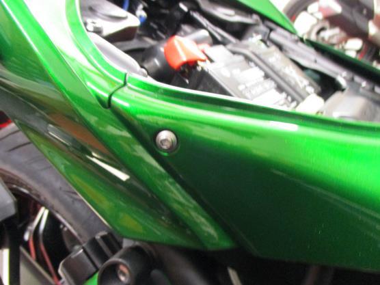
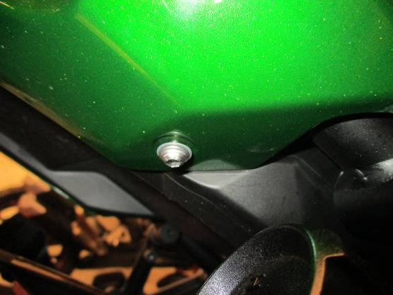
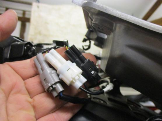
10 Page 10 Picture 43 Picture 44 Picture 45 Picture 46 FITTING INSTRUCTIONS To fit the R&G tail tidy, first remove the pillion seat using the key as shown in picture 1. Remove the main rider seat as shown in picture 2. Remove the two bolts arrowed in picture 3. Remove the four push rivets arrowed in pictures 4 and 5 (please be aware all the fairing bolts have plastic washers which should be reused on assembly). Remove the bolt arrowed in picture 6. Remove the push rivet arrowed in picture 7. Remove the bolt arrowed in picture 8. Remove the push rivet arrowed in picture 9. Carefully ease the right-hand side seat infill panel away from the frame and remove the push rivet arrowed in picture 10. Carefully remove the infill panel as shown in picture 11. Remove the bolt arrowed in picture 12. Remove the push rivet and bolt arrowed in picture
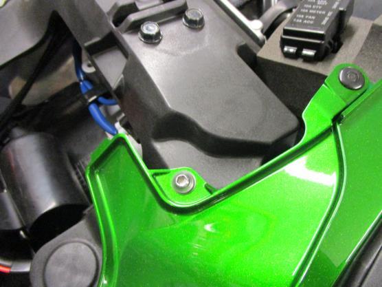
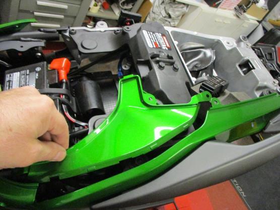
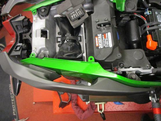
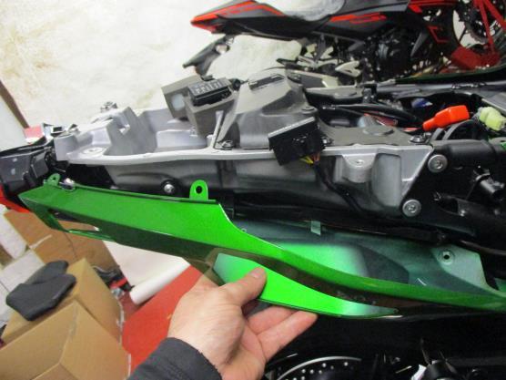
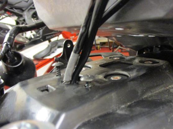
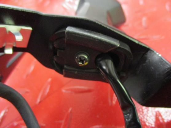
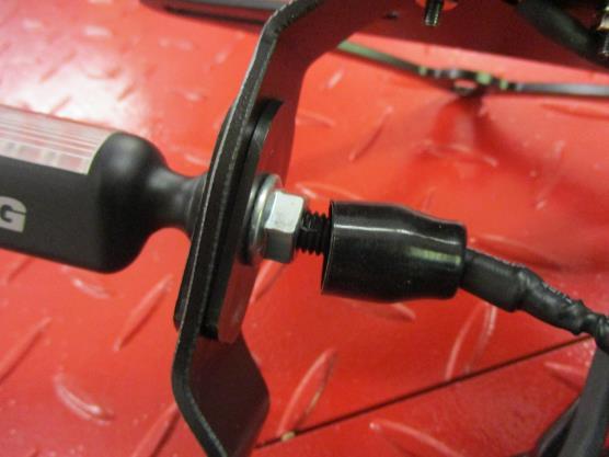
11 Page 11 Carefully ease the left-hand side seat infill panel away from the frame and remove the push rivet arrowed in picture 14. Carefully remove the infill panel as shown in picture 15. Remove the two hex headed bolts arrowed in picture 16 and remove the left-hand side grab rail. Remove the two hex headed bolts arrowed in picture 17 and remove the right-hand side grab rail. Remove the two push rivets arrowed in picture 18. Remove the two bolts arrowed in pictures 19 and 20. Carefully remove the two seat cowls as shown in pictures 21 and 22. Remove the two bolts arrowed in pictures 23 and 24. Remove the four bolts arrowed in picture 25 while supporting the original licence plate bracket from below. Slide the rubber plug socket cover along the wiring loom to give access to the indicator and licence plate illuminator as indicated in picture 26. Disconnect the three wiring plug sockets arrowed in picture 26. Gently lower the original licence plate bracket and remove the two screws arrowed in picture 27. If reusing the original indicators Remove the four screws arrowed in picture 28. Remove the plastic wiring cover/splash guard to allow access to the indicators. Remove the indicator clamp screw arrowed in picture 29 Remove the indicator clamp bracket as arrowed in picture 30. Remove the indicator spreader plate as arrowed in picture 31. Gently squeeze the indicator stem and remove the indicator as shown in picture 32 Repeat the above steps to remove the opposite indicator. Fit the indicators into the new licence plate bracket (item 14) and secure as shown in pictures 33, 34, 35 and 36. If using the mini indicators To fit the R&G Mini Indicators (R&G mini indicator product code RG371 for LED type or RG372 for Aero Style led type). Position the two indicator adaptors (item 9 I0039) onto the wiring of each indicator, ensuring the sides facing each other have the raised centre profile, before fitting the flanged nut supplied, as shown in pictures 37 and 38. Feed the indicator wiring through the nut/wire cover (item 8) as shown in pictures 39 and 41 (it helps if a small amount of liquid detergent is used) and position the nut cover over the nut. Fit one length of smaller heat-shrink (item 12) to the wires of each indicator so it goes over the tail of the nut/wire covers. Fit the R&G licence plate illuminator (item 10) as shown in pictures 40 and 41, please note you will have to fit the light shroud and use a small amount of adhesive to hold it in position. Fit one length of the smaller heat-shrink (item 12) to the wire. To fit R&G licence plate illuminator (item 10), the OEM licence plate illuminator wiring loom will need to be cut and shut In order to re-use the connector to connect to the wiring loom. This is done by cutting the connectors off the OEM licence plate illuminator connector (minimum of 50mm away from the connector), peel the end of each wire and 11
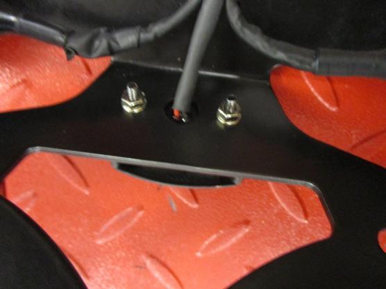
12 fit one female bullet connector (item 5) to each exposed wire. Connect the female bullet connectors just fitted to the male bullet connectors on the R&G licence plate illuminator. Page 12 Fit the licence plate mounting bracket (item 1) to the licence plate bracket (item 14) using the M6x8mm long button head bolts with washers (items 2 and 15) as shown in picture 42 (please leave the bolts loose at this stage). Tidy the wiring to the licence plate bracket using the supplied clips and cable ties (items 6 and 7) as shown in picture 42. Offer the new licence plate bracket into position while feeding the wiring through the hole in the under-tray as shown in picture 43. Fit the four button head bolts with washers (items 2 and 4) through the four holes in the new licence plate mounting bracket (item 1) as shown in picture 44. Secure using the four nuts with washers (items 2 and 3) as shown in picture 45, please ensure the wires are not crushed. When using led mini indicators, the OEM indicator wiring will need to be cut and shut in order to re-use the original connectors to connect the R&G Mini Indicators to the wiring loom. This is done by cutting the connectors off the original indicators (approximately 50mm from the plug socket nearest the indicator, this means the original resistor remains in the loom as arrowed below), before fitting the female bullet connectors (item 5) to the exposed wiring and connecting to the R&G indicators. It is a good idea to test the indicators and licence plate illuminator at this stage, plug all sockets into the loom to check at this stage (if illumination fails, swap the bullet connections around). Refit all panels as original. Adjust the new licence plate bracket to suit using the three bolts from the underside (if using luggage care must be taken to ensure the luggage will not damage indicators when being removed). Refit the seats as original and licence plate (it may require drilling). IMPORTANT: IF FITTING A FULL-SIZE LICENCE PLATE AND PLACING IT FAR DOWN ON THE LICENCE PLATE HANGER, THERE IS A SMALL CHANCE OF THE LICENCE PLATE HITTING THE BACK WHEEL UNDER HEAVY LOAD AND OVER LARGE BUMPS IN THE ROAD. IT IS YOUR RESPONSIBILITY TO CHECK FOR THIS POSSIBILITY AND TAKE AVOIDING ACTION. FAILURE TO CHECK THIS COULD RESULT IN SERIOUS INJURY. Depending on local laws, attach enclosed reflector (item 13) in an appropriate location. Test the licence plate illuminator, indicators and all lights before riding. 12
13 ISSUE 1 25/06/2018 (NSY) Page 13 CONSUMER NOTICE The catalogue description and any exhibition of samples are only broad indications of the Products and R&G may make design changes which do not diminish their performance or visual appeal and supplying them in such state shall conform to the order. The Buyer acknowledges no representation or warranty (other than as to title) has been given or will apply to the Products other than those in R&G s order or confirmation and the Buyer confirms it has chosen the Products as being of merchantable quality and suitable for its particular purposes. Where R&G fits the Products or undertakes other services it shall exercise reasonable skill and care and rectify any fault free of charge unless the workmanship has been disturbed. The Buyer is responsible for ensuring that the warranty on the motorcycle is not affected by the fitting of the Products. On return of any defective Products R&G shall at its option either supply a replacement or refund the purchase money but shall not be liable if the Products have been modified or used or maintained otherwise than in accordance with R&G s or manufacturer s instructions and good engineering practice or if the defect arises from accident or neglect. Other than identified above and subject to R&G not limiting its liability for causing death and personal injury, it shall not be liable for indirect or consequential loss and otherwise its liability shall be limited to the amounts paid by the Buyer for the Products or the fitting or service concerned. These terms do not affect the Buyer s statutory rights. R&G RACING RETURNS POLICY (NON-FAULTY GOODS) Returns must be pre-authorised (if not pre-authorised the return will be rejected). Goods may only be returned direct to us if they were purchased direct from us (customer must prove if necessary). Otherwise to be returned to original vendor. Goods must be in re-sellable condition, in the opinion of. All returns are subject to a 25% restocking and handling fee (25% of the gross value exc. P&P at the prevailing price at time of purchase). The customer must pay any and all carriage charges. No returns of discontinued products, unless within 14 days of purchase. This policy does not affect your statutory rights and does not refer to faulty goods. 13
14 NOTICE DE MONTAGE LP0247BK SUPPORT DE PLAQUE KAWASAKI H2 SX 2018 (POUR CLIGNOTANTS STANDARDS ET MINI CLIGNOTANTS R&G (8mm)) Page 14 Le kit contient les articles exposés ci-dessous, vérifier que toutes les pièces soient présentes avant de procéder au montage. La façon dont le kit est emballé ne correspond pas forcément à la façon de monter les pièces sur la moto. LES PARTIES PRESENTEES PEUVENT ETRE UNIQUEMENT REPRESENTATIVES (POUR LA CLARTE DES INSTRUCTIONS UNIQUEMENT) Notice disponible au téléchargement sur VALEURS DE SERRAGE M4 BOULON = 8Nm M5 BOULON = 12Nm M6 BOULON = 15Nm M8 BOULON = 20 Nm M10 BOULON = 40 Nm Notez que si les kits sont emballés avec des rondelles en caoutchouc servant à tenir les composants, ces rondelles doivent être jetées! OUTILS REQUIS Clés Allen 3, 4 et 5mm. Clé à cliquet + douilles 6, 10 et 12mm. Tournevis cruciforme. Pinces électriques. Un peu de superglue. 14
15 Page LÉGENDE ARTICLE 1 = SUPPORT DE PLAQUE D IMMATRICULATION (TB0247 PARTIE 1) (x1). ARTICLE 2 = M6 RONDELLE (x11). ARTICLE 3 = M6 ÉCROUS (x4). ARTICLE 4 = M6 x 20mm BOULONS (x4). ARTICLE 5 = CONNECTEURS DE FEU DE PLAQUE / CLIGNOTANTS (CON0004) (x3). ARTICLE 6 = CLIPS CÂBLE (x4). ARTICLE 7 = COLLIERS DE SERRAGE (x4). ARTICLE 8 = CACHE ÉCROU DE CLIGNOTANT EN SILICONE (IWC0002) (x2). ARTICLE 9 = ADAPTATEURS DE MINI CLIGNOTANTS (I0039) (x4). ARTICLE 10 = ASSEMBLAGE FEU DE PLAQUE (LA0002) (x1). ARTICLE 11 = 150mm LONGUEUR DE MANCHON THERMO RÉTRACTABLE (x2). ARTICLE 12 = 230mm LONGUEUR DE PETIT MANCHON THERMO RÉTRACTABLE (x3). ARTICLE 13 = RÉFLECTEUR (REFL 1) (x1). 15
16 ARTICLE 14 = SUPPORT DE PLAQUE (TB0247 PART 2) (x1). ARTICLE 15 = M6 x 8mm BOULONS (x3). Page 16 NOTICE DE MONTAGE Pour monter le support de plaque R&G, commencez par enlever le siège passage à l aide de la clé, voir photo 1. Enlever le siège principal, voir photo 2. Enlever les 2 boulons, voir photo 3. Enlever les 4 rivets indiqués sur les photos 4 et 5 (attention tous les boulons possèdent une rondelle qui doit être réutilisée dans l assemblage). Enlever le boulon indiqué sur la photo 6. Enlever le rivet indiqué sur la photo 7. Enlever le boulon indiqué sur la photo 8. Enlever le rivet indiqué sur la photo 9. Enlever délicatement le panneau latéral de siège côté droit de son support cadre puis enlever le rivet indiqué sur la photo 10. Enlever délicatement le panneau interne, voir photo 11. Enlever le boulon indiqué sur la photo 12. Enlever le rivet et le boulon indiqués sur la photo 13. Enlever délicatement le panneau latéral de siège côté gauche de son support cadre puis enlever le rivet indiqué sur la photo 14. Enlever délicatement le panneau interne, voir photo 15. Enlever les 2 boulons indiqués sur la photo 16 puis enlever la barre d attache du côté gauche. Enlever les 2 boulons indiqués sur la photo 17 puis enlever la barre d attache du côté droit. Enlever les 2 rivets indiqués sur la photo 18. Enlever les 2 boulons indiqués sur les photos 19 et 20. Enlever délicatement les 2 capots de siège, voir photos 21 et 22. Enlever les 2 boulons indiqués sur les photos 23 et 24. Enlever les 4 boulons indiqués sur la photo 25 tout en supportant le support de plaque d origine par dessous. Glisser le cache prise en caoutchouc sur le faisceau de câbles pour accéder au clignotant et eu feu de plaque, voir photo 26. Déconnecter les 3 prises de câbles, voir photo 26. Abaisser le support de plaque d origine puis enlever les 2 vis indiquées sur la photo 27. Si vous réutilisez les clignotants d origine Enlever les 4 vis, voir photo 28. Enlever le cache fil en plastique / protection contre les projections, pour accéder aux clignotants. Enlever la vis de clip du clignotant, voir photo 29 Enlever le support de clip du clignotant, voir photo 30. Enlever la plaque d écartement du clignotant, voir photo 31. Tordez légèrement la tige de clignotant puis enlever le clignotant, voir photo 32 Répéter les étapes supérieures pour enlever le clignotant opposé. 16
17 Monter les clignotants sur le nouveau support de plaque (article 14) puis serrer, voir photos 33, 34, 35 et 36. Page 17 Si vous installez les mini clignotants Pour monter les mini clignotants R&G (mini clignotant R&G code produit RG371pour type LED ou RG372 pour type LED latérale). Positionner les 2 adaptateurs de clignotants (article 9 I0039) sur le fil de chaque clignotant, en veillant à ce que les côtés qui se font face aient le profil central relevé, avant d insérer un écrou fourni, voir photos 37 et 38. Passer le fil de clignotant à travers le cache écrou/fil (article 8), voir photos 39 et 41 (utiliser un peu de détergent facilitera cette opération) puis positionner le cache écrou sur l écrou. Appliquer une longueur de petit manchon thermo rétractable (article 12) sur les fils de chaque clignotant de façon à ce qu il se place sur le support des caches écrou/fil. Monter le feu de plaque R&G (article 10), voir photos 40 et 41, notez que vous devrez monter le linceul de feu et utiliser un peu d adhésif pour le maintenir en position. Appliquer une longueur de petit manchon thermo rétractable (article 12) sur le fil. Pour monter le feu de plaque R&G (article 10), le faisceau de câble du feu de plaque d origine devra être coupé et fermé afin de réutiliser le connecteur pour connecter le faisceau de câble. Cela s effectue en coupant les connecteurs à minimum 50mm des connecteurs de feu de plaque d origine, décortiquer l extrémité de chaque fil puis monter un connecteur femelle (article 5) sur chaque extrémité de fil. Connecter les connecteurs femelles tout juste montés sur les connecteurs mâles du feu de plaque R&G. Monter le support de fixation de plaque (article 1) sur le support de plaque (article 14) en utilisant les boulons M6x8mm munis de rondelles (articles 2 and 15), voir photo 42. (ne pas serrer les boulons pour le moment). Serrer le fil sur le support de plaque en utilisant les clips fournis et colliers de serrage (articles 6 et 7), voir photo 42. Monter le nouveau support de plaque en position tout en passant le fil dans le trou du sous plateau, voir photo 43. Insérer les 4 boulons avec rondelles (articles 2 and 4) dans les 4 trous du nouveau support de plaque (article 1), voir photo 44. Fixer à l aide des 4 écrous et rondelles (articles 2 and 3), voir photo 45, veiller à ce que les fils ne soient pas pincés. Si vous utilisez les mini clignotants à LED, le fil de clignotant d origine devra être coupé puis fermé, pour réutiliser les connecteurs d origine pour connecter les mini clignotants R&G sur le faisceau de câbles. Cela s effectue en coupant les connecteurs des clignotants d origine (à environ 50mm de la prise la plus proche du clignotant, cela signifie que la résistance d origine reste dans le faisceau, voir ci-dessous), avant de monter les connecteurs femelle (article 5) sur l extrémité du fil puis connecter les clignotants R&G. Il est judicieux de vérifier le fonctionnement des clignotants et du feu de plaque à ce stade, en branchant toutes les prises dans le faisceau (si l éclairage échoue, tourner les connecteurs). 17
18 Page 18 Remonter tous les carénages comme à l origine. Ajuster le nouveau support de plaque en utilisant les 3 boulons par le dessous (si vous utilisez un bagage, attention à ce qu il n endommage pas les clignotants lorsque vous l enlevez). Remonter les sièges comme à l origine et la plaque d immatriculation (cela nécessite peut-être un perçage). IMPORTANT : Si vous installez une grosse plaque, il y a un risque que la plaque entre en contact avec la roue arrière en cas de choc sur la route (bosse, grosse charge etc..). Il est de votre responsabilité de vérifier que cela ne puisse pas se produire. Ne pas effectuer ces vérifications peut entrainer des dommages ainsi que des blessures graves pour le pilote. Selon les lois locales, attacher le réflecteur rouge (article 13) à l endroit approprié. Tester le feu de plaque, les clignotants, ainsi que l ensemble des feux avant de prendre la route. ISSUE 1 25/06/2018 (NSY) 18
19 Page 19 CONSUMER NOTICE The catalogue description and any exhibition of samples are only broad indications of the Products and R&G may make design changes which do not diminish their performance or visual appeal and supplying them in such state shall conform to the order. The Buyer acknowledges no representation or warranty (other than as to title) has been given or will apply to the Products other than those in R&G s order or confirmation and the Buyer confirms it has chosen the Products as being of merchantable quality and suitable for its particular purposes. Where R&G fits the Products or undertakes other services it shall exercise reasonable skill and care and rectify any fault free of charge unless the workmanship has been disturbed. The Buyer is responsible for ensuring that the warranty on the motorcycle is not affected by the fitting of the Products. On return of any defective Products R&G shall at its option either supply a replacement or refund the purchase money but shall not be liable if the Products have been modified or used or maintained otherwise than in accordance with R&G s or manufacturer s instructions and good engineering practice or if the defect arises from accident or neglect. Other than identified above and subject to R&G not limiting its liability for causing death and personal injury, it shall not be liable for indirect or consequential loss and otherwise its liability shall be limited to the amounts paid by the Buyer for the Products or the fitting or service concerned. These terms do not affect the Buyer s statutory rights. R&G RACING RETURNS POLICY (NON-FAULTY GOODS) Returns must be pre-authorised (if not pre-authorised the return will be rejected). Goods may only be returned direct to us if they were purchased direct from us (customer must prove if necessary). Otherwise to be returned to original vendor. Goods must be in re-sellable condition, in the opinion of. All returns are subject to a 25% restocking and handling fee (25% of the gross value exc. P&P at the prevailing price at time of purchase). The customer must pay any and all carriage charges. No returns of discontinued products, unless within 14 days of purchase. This policy does not affect your statutory rights and does not refer to faulty goods. 19
20 MONTAGEANLEITUNG FÜR LP0247BK KENNZEICHENHALTER KAWASAKI H2 SX 2018 (VERWENDUNG MIT STANDARDBLINKER UND R&G MINIBLINKER (8mm)) Page 20 ALLE GELIEFERTEN TEILE SIND UNTEN ABGEBILDET UND GEKENNZEICHNET. BEVOR SIE MIT DER MONTAGE BEGINNEN, ÜBERPRÜFEN SIE SORGFÄLTIG, DASS ALLE TEILE VORHANDEN SIND. Die Verpackung der Teile stellt nicht die Reihenfolge der Montage dar. DIE UNTEN ABGEBILDETEN TEILE DIENEN LEDIGLICH ZUR ERKLÄRUNG Eine digitale Version dieser Montageanleitung kann auf folgender Seite heruntergeladen werden: ANZUGSDREHMOMENTE: M4 SCHRAUBE = 8 NM M5 SCHRAUBE = 12NM M6 SCHRAUBE = 15NM M8 SCHRAUBE = 20NM M10 SCHRAUBE = 40NM Hinweis für Kits mit Plastikunterlegscheiben an den Schrauben Diese Plastikunterlegscheiben werden nicht für den Einbau benötigt! SIE BENÖTIGEN FOLGENDES WERKZEUG Satz Inbusschlüssel inkl. 3, 4 & 5mm Inbusschlüssel Steckschlüsselsatz inkl. 6, 10 und 12mm Steckschlüssel Kreuzschlitzschraubendreher Elektroniker Zange etwas Sekundenkleber 20
21 Page LIEFERUMFANG ARTIKEL 1 = KENNZEICHENHALTER HALTERUNG (TB0247 TEIL 1) (x1) ARTIKEL 2 = M6 UNTERLEGSCHEIBE (x11) ARTIKEL 3 = M6 SELBSTSICHERNDE MUTTER (x4) ARTIKEL 4 = M6 x 20mm INBUSSCHRAUBE (x4) ARTIKEL 5 = VERBINDUNG FÜR KENNZEICHENBELEUCHTUNG/BLINKER (CON0004) (x3) ARTIKEL 6 = KABELCLIP (x4) ARTIKEL 7 = KABELBINDER (x4) ARTIKEL 8 = ABDECKUNGEN FÜR DIE MUTTER (BLINKER) AUS SILIKON (IWC0002) (x2) ARTIKEL 9 = MINIBLINKER ADAPTER (I0039) (x4) ARTIKEL 10 = KENNZEICHENBELEUCHTUNG (LA0002) (x1) ARTIKEL 11 = 150mm SCHRUMPFSCHLAUCH GROSS (x2) ARTIKEL 12 = 230mm SCHRUMPFSCHLAUCH KLEIN (x3) 21
22 ARTIKEL 13 = RÜCKSTRAHLER (REFL 1) (x1) ARTIKEL 14 = KENNZEICHENHALTER (TB0247 TEIL 2) (x1) ARTIKEL 15 = M6 x 8mm INBUSSCHRAUBE (x3) Page 22 MONTAGEANLEITUNG Um den R&G Kennzeichenhalter montieren zu können, entfernen Sie zuerst den Soziussitz. Verwenden Sie hierfür den Schlüssel siehe Abbildung 1. Entfernen Sie den Fahrersitz wie in Abbildung 2 abgebildet. Entfernen Sie die zwei Schrauben, die in Abbildung 3 gekennzeichnet sind. Entfernen Sie die vier Plastiknieten, die in den Abbildungen 4 und 5 markiert sind (Hinweis: alle Verkleidungsschrauben haben Unterlegscheiben, die bei der Montage wiederverwendet werden sollen). Entfernen Sie die Plastikniete, die in Abbildung 7 gekennzeichnet ist. Entfernen Sie die Schraube, die in Abbildung 8 markiert ist. Entfernen Sie die Plastikniete, die in Abbildung 9 gekennzeichnet ist. Entfernen Sie das rechte Verkleidungsteil für den Sitz vom Rahmen und entfernen Sie die Plastikniete, die in Abbildung 10 gekennzeichnet ist. Entfernen Sie das Verkleidungsteil, das in Abbildung 11 abgebildet ist. Entfernen Sie die Schraube, die in Abbildung 12 gekennzeichnet ist. Entfernen Sie die Plastikniete und die Schraube, die in Abbildung 13 markiert sind. Entfernen Sie das linke Verkleidungsteil für den Sitz vom Rahmen und entfernen Sie die Plastikniete, die in Abbildung 14 gekennzeichnet ist. Entfernen Sie das Verkleidungsteil, das in Abbildung 15 abgebildet ist. Entfernen Sie zwei Sechskantschrauben, die in Abbildung 16 gekennzeichnet sind und entfernen Sie den linken Haltegriff. Entfernen Sie zwei Sechskantschrauben, die in Abbildung 17 gekennzeichnet sind und entfernen Sie den rechten Haltegriff. Entfernen Sie die zwei Plastiknieten, die in Abbildung 18 markiert sind. Entfernen Sie die zwei Schrauben, die in den Abbildungen 19 und 20 markiert sind. Entfernen Sie die zwei Heckverkleidungen (siehe Abbildungen 21 und 22). Entfernen Sie zwei Schrauben, die in den Abbildungen 23 und 24 markiert sind. Entfernen Sie die vier Schrauben, die in Abbildung 25 markiert sind den original Kennzeichenhalter dabei von unten stützen. Schieben Sie die Abdeckung für die Steckverbinder aus Gummi am Kabelbaum entlang, um Zugang zu den Blinkern und der Kennzeichenbeleuchtung zu ermöglichen siehe Abbildung 26. Trennen Sie die drei Steckverbinder, die in Abbildung 26 mit Pfeilen gekennzeichnet sind. Den original Kennzeichenhalter vorsichtig herabsetzen und die zwei Schrauben entfernen, die in Abbildung 27 gekennzeichnet sind. Wenn Sie die original Blinker verwenden Entfernen Sie die vier Schrauben, die in Abbildung 28 gekennzeichnet sind. Entfernen Sie die Plastikabdeckung für die Kabel/ den Spritzschutz, um Zugang zu den Blinkern zu ermöglichen. Entfernen Sie die Schraube für die Klemmhalterung für den Blinker siehe Abbildung 29. Entfernen Sie die Klemmhalterung für den Blinker, die in Abbildung 30 gekennzeichnet ist. 22
23 Page 23 Entfernen Sie die Distanzplatte siehe Abbildung 31. Vorsichtig den Stiel zusammendrücken und den Blinker entfernen wie in Abbildung 32 abgebildet. Diese Schritte wiederholen, um den zweiten Blinker zu entfernen. Montieren Sie die Blinker am neuen Kennzeichenhalter (Artikel 14) und wie in den Abbildungen 33, 34, 35 und 36 abgebildet befestigen. Wenn Sie R&G Miniblinker verwenden: Die R&G Miniblinker (R&G Artikel-Nr. RG371 = LED oder RG372 = Aero LED) montieren Sie wie folgt: Positionieren Sie die zwei Blinker-Adapter (Artikel 9 I0039) an den Kabeln der zwei Blinker. Bitte darauf achten, dass die Flächen mit erhöhter Profilmitte sich gegenüber liegen, bevor Sie die Bundmutter vom Kit montieren siehe Abbildungen 37 und 38. Führen Sie Blinkerkabel durch die Mutter/Kabelabdeckung (Artikel 8) wie in den Abbildungen 39 und 41 abgebildet (etwas Spülmittel kann hierbei helfen) und die Abdeckung für die Mutter an der Mutter anbringen. Je eine Länge des kleineren Schrumpfschlauchs (Artikel 12) an den Kabeln für jeden Blinker anbringen, sodass das Ende der Mutter/Kabelabdeckungen auch bedeckt ist. Montieren Sie die R&G Kennzeichenbeleuchtung (Artikel 10) wie in den Abbildungen 40 und 41 abgebildet. Bitte beachten Sie, dass die Abdeckung für die Kennzeichenbeleuchtung mit etwas Sekundenkleber in Position befestigt werden muss. 1 x Schrumpfschlauch (Artikel 12) am Kabel anbringen. Um die R&G Kennzeichenbeleuchtung (Artikel 10) montieren zu können, muss die original Verkabelung für die Kennzeichenbeleuchtung abgetrennt und abisoliert werden, sodass der Steckverbinder verwendet werden kann. Den original Steckverbinder mit mindestens 50 mm Kabel (das Kabel noch mit dem Steckverbinder verbunden) abschneiden. Die Kabelenden abisolieren und die weiblichen Kabelverbinder (Artikel 5) an den offenen Enden der Kabel anbringen. Verbinden Sie die männlichen Kabelverbinder an der R&G Kennzeichenbeleuchtung mit den soeben montierten weiblichen Kabelverbindern. Die Halterung für den Kennzeichenhalter (Artikel 1) am Kennzeichenhalter (Artikel 14) montieren verwenden Sie hierfür die M6x8mm Inbusschrauben mit Unterlegscheiben (Artikel 2 und 15) wie in Abbildung 42 abgebildet (bitte die Schrauben zu diesem Zeitpunkt nicht festdrehen). Verwenden Sie die mitgelieferten Clips und Kabelbinder (Artikel 6 und 7), um die Kabel für den Kennzeichenhalter ordentlich zu verstauen siehe Abbildung 42. Den neuen Kennzeichenhalter in Position bringen und die Kabel dabei durch die Öffnung in der unteren Abdeckung führen siehe Abbildung 43. Montieren Sie die vier Inbusschrauben mit Unterlegscheiben (Artikel 2 und 4) an den vier Öffnungen im neuen Kennzeichenhalter (Artikel 1) wie in Abbildung 44 abgebildet. Mit den vier Muttern und Unterlegscheiben (Artikel 2 und 3) befestigen wie in Abbildung 45 abgebildet bitte darauf achten, Sie, dass die Kabel nicht eingeklemmt sind. Wenn Sie LED Miniblinker verwenden, muss die original Verkabelung abgetrennt und abisoliert werden, um die original Verbindungen wieder zu verwenden und die R&G Miniblinker am Kabelbaum anzuschließen. Die original Steckverbinder (ca. 50 mm vom Steckverbinder ganz in der Nähe der Blinker, sodass der original Widerstand am Kabelstrang bleibt wie unten mit Pfeilen gekennzeichnet) von der Originalblinkern abschneiden. Die 23

24 Page 24 weiblichen Kabelverbindern (Artikel 5) an den offenen Enden der Kabel anbringen und mit den R&G Blinkern verbinden. Es empfiehlt sich nun die Funktion der Kennzeichenbeleuchtung und Blinkern zu testen alle Verbinder am Kabelbaum anschließen und überprüfen. (falls die Beleuchtung nicht funktionieren sollte, die Kabelverbinder untereinander tauschen). Montieren Sie alle Verkleidungsteile wie ursprünglich wieder. Den neuen Kennzeichenhalter mittels der drei Schrauben an der Unterseite einstellen. (wenn Sie Seitenkoffer benutzen, müssen Sie darauf achten, dass die Blinker nicht beschädigt werden, wenn die Koffer abmontiert werden. Montieren Sie die Sitz wie ursprünglich wieder und montieren Sie das amtliche Kennzeichen (Bohrungen im Kennzeichen evtl. notwendig). WICHTIG: WENN EIN GROSSES KENNZEICHEN ZU WEIT NACH UNTEN MONTIERT WIRD, BESTEHT BEI SCHWEREM LAST ODER DURCH GROSSE BODENWELLEN EIN GERINGES RISIKO, DASS DAS KENNZEICHEN AN DAS HINTERRAD STOSSEN KANN. ES LIEGT IN IHRER VERANTWORTUNG DIES ZU ÜBERPRÜFEN UND, WENN NOTWENDIG, VORZUBEUGENDE MASSNAHMEN ZU ERGREIFEN. DIE NICHTBEACHTUNG DIESES SICHERHEITSHINWEIS KANN ZU SCHWEREN VERLETZUNGEN FÜHREN. Entsprechend der gesetzlichen Vorschriften, den mitgelieferten Rückstrahler (Artikel 13) an die dafür vorgesehene Stelle anbringen. Überprüfen Sie die Funktion der Beleuchtung (Blinker und Kennzeichenhalterbeleuchtung) vor Gebrauch des Fahrzeuges. CONSUMER NOTICE The catalogue description and any exhibition of samples are only broad indications of the Products and R&G may make design changes which do not diminish their performance or visual appeal and supplying them in such state shall conform to the order. The Buyer acknowledges no representation or warranty (other than as to title) has been given or will apply to the Products other than those in R&G s order or confirmation and the Buyer confirms it has chosen the Products as being of merchantable quality and suitable for its particular purposes. Where R&G fits the Products or undertakes other services it shall exercise reasonable skill and care and rectify any fault free of charge unless the workmanship has been disturbed. The Buyer is responsible for ensuring that the warranty on the motorcycle is not affected by the fitting of the Products. On return of any defective Products R&G shall at its option either supply a replacement or refund the purchase money but shall not be liable if the Products have been modified or used or maintained otherwise than in accordance with R&G s or manufacturer s instructions and good engineering practice or if the defect arises from accident or neglect. Other than identified above and subject to R&G not limiting its liability for causing death and personal injury, it shall not be liable for indirect or consequential loss and otherwise its liability shall be limited to the amounts paid by the Buyer for the Products or the fitting or service concerned. These terms do not affect the Buyer s statutory rights. R&G RACING RETURNS POLICY (NON-FAULTY GOODS) Returns must be pre-authorised (if not pre-authorised the return will be rejected). Goods may only be returned direct to us if they were purchased direct from us (customer must prove if necessary). Otherwise to be returned to original vendor. Goods must be in re-sellable condition, in the opinion of. All returns are subject to a25% restocking and handling fee (25% of the gross value exc. P&P at the prevailing price at time of purchase). The customer must pay any and all carriage charges. No returns of discontinued products, unless within 14 days of purchase. This policy does not affect your statutory rights and does not refer to faul 24
Fitting Instructions for DG0017 BK Downpipe Grille BMW F800GT 2013
 Fitting Instructions for DG0017 BK Downpipe Grille BMW F800GT 2013 In This Kit There Should Be 1 x Downpipe Grille (DG0017) 2 x M5 Nyloc nuts PICTURE 1 PICTURE 2 PICTURE 3 PICTURE 4 1 PICTURE 5 PICTURE
FITTING INSTRUCTIONS FOR LP0104BK LICENCE PLATE BRACKET HONDA CBR 250R 2011/ WK SP250 / 125 / 50
 FITTING INSTRUCTIONS FOR LP0104BK LICENCE PLATE BRACKET HONDA CBR 250R 2011/ WK SP250 / 125 / 50 Page 1 THIS KIT CONTAINS THE ITEMS PICTURED AND LABELLED BELOW. DO NOT PROCEED UNTIL YOU ARE SURE ALL PARTS
Fitting Instructions for RAD0129BK Radiator Guard MV AGUSTA F3 2012
 Fitting Instructions for RAD0129BK Radiator Guard MV AGUSTA F3 2012 In This Kit There Should Be 1x Radiator Guard (RAD0129BK) 2x 100mm Lengths of self-adhesive Foam 1x Cable Tie Picture 1 Picture 2 Picture
FITTING INSTRUCTIONS FOR LP0245BK LICENCE PLATE BRACKET KAWASAKI NINJA (FOR USE WITH STANDARD AND R&G MINI INDICATORS (8mm))
)") FITTING INSTRUCTIONS FOR LP0245BK LICENCE PLATE BRACKET KAWASAKI NINJA 400 2018 (FOR USE WITH STANDARD AND R&G MINI INDICATORS (8mm)) Page 1 THIS KIT CONTAINS THE ITEMS PICTURED AND LABELLED BELOW. DO
FITTING INSTRUCTIONS FOR LP0245BK LICENCE PLATE BRACKET KAWASAKI NINJA 400 2018 (FOR USE WITH STANDARD AND R&G MINI INDICATORS (8mm)) Page 1 THIS KIT CONTAINS THE ITEMS PICTURED AND LABELLED BELOW. DO
Fitting Instructions for SRG0013 Radiator Guard KAWASAKI ER6-N / ER6-F / 650 Versys 10-
 Fitting Instructions for SRG0013 Radiator Guard KAWASAKI ER6-N 09-11 / ER6-F 09-11 / 650 Versys 10- PICTURE 1 PICTURE 2 In This Kit There Should Be 1x Radiator Guard 1x M6x20mm long button head bolt 1x
Fitting Instructions for RAD0185BK Radiator Guard TRIUMPH STREET TRIPLE RX 2015
 Fitting Instructions for RAD0185BK Radiator Guard TRIUMPH STREET TRIPLE RX 2015 In This Kit There Should Be 1x Radiator Guard (RAD0185BK) 4x 100mm Lengths of self-adhesive Foam Picture 1 Picture 2 Picture
Fitting Instructions for DG0012 BK Downpipe Grille KAWASAKI NINJA
 Fitting Instructions for DG0012 BK Downpipe Grille KAWASAKI NINJA 300 2013-- In This Kit There Should Be 1x Downpipe Grille (DG0012) 2x M6 x 30mm Button Head Bolts 2 3 4 1 5 6 Picture 1 Picture 2 1 Picture
FITTING INSTRUCTIONS FOR LP0248BK LICENCE PLATE BRACKET KTM DUKE
 FITTING INSTRUCTIONS FOR LP0248BK LICENCE PLATE BRACKET KTM DUKE 790 18- Page 1 THIS KIT CONTAINS THE ITEMS PICTURED AND LABELLED BELOW. DO NOT PROCEED UNTIL YOU ARE SURE ALL PARTS ARE PRESENT. Please
Fitting Instructions for DG0011 BK Downpipe Grille TRIUMPH TROPHY 2012
 Fitting Instructions for DG0011 BK Downpipe Grille TRIUMPH TROPHY 2012 In This Kit There Should Be 1x Downpipe Grille (DG0011) Picture 1 Picture 2 1 FITTING INSTRUCTIONS Picture 3 Picture 4 TOOLS REQUIRED
Fitting Instructions for RAD0151BK Radiator Guard BMW R1200GS 2013
 Fitting Instructions for RAD0151BK Radiator Guard BMW R1200GS 2013 In This Kit There Should Be 2x Radiator Guard (RAD0151BK Left & Right) 2x 100mm Lengths of self-adhesive Foam Picture 1 Picture 2 Picture
FITTING INSTRUCTIONS FOR LP0127BK LICENCE PLATE BRACKET YAMAHA T-MAX
 FITTING INSTRUCTIONS FOR LP0127BK LICENCE PLATE BRACKET YAMAHA T-MAX 530 2012 THIS KIT CONTAINS THE ITEMS PICTURED AND LABELLED BELOW. DO NOT PROCEED UNTIL YOU ARE SURE ALL PARTS ARE PRESENT. Please note
FITTING INSTRUCTIONS FOR AB0013BK ADVENTURE BARS APRILIA CAPONORD
 FITTING INSTRUCTIONS FOR AB001BK ADVENTURE BARS APRILIA CAPONORD 1200 201-1 PICTURE A PICTURE B THIS KIT CONTAINS THE ITEMS PICTURED AND LABELLED BELOW. DO NOT PROCEED UNTIL YOU ARE SURE ALL PARTS ARE
FITTING INSTRUCTIONS FOR LP0068BK & LP0070BK LICENCE PLATE BRACKET KTM RC8 2008
 FITTING INSTRUCTIONS FOR LP0068BK & LP0070BK LICENCE PLATE BRACKET Please note that the way the kit is packed does not necessarily represent the way of mounting to the bike Please note that in cases where
FITTING INSTRUCTIONS FOR SBP0005 SPINDLE BLANKING PLATES DUCATI DIAVEL, MONSTER & PANIGALE MULTISTRADA 1200
 FITTING INSTRUCTIONS FOR SBP0005 SPINDLE BLANKING PLATES DUCATI DIAVEL, MONSTER1200 14- & PANIGALE 1199 2011- MULTISTRADA 1200 THIS KIT CONTAINS THE ITEMS PICTURED AND LABELLED BELOW. DO NOT PROCEED UNTIL
FITTING INSTRUCTIONS FOR LP0158 LICENCE PLATE BRACKET KTM 1290 SUPER DUKE R 2014
 FITTING INSTRUCTIONS FOR LP0158 LICENCE PLATE BRACKET KTM 1290 SUPER DUKE R 2014 Page 1 THIS KIT CONTAINS THE ITEMS PICTURED AND LABELLED BELOW. DO NOT PROCEED UNTIL YOU ARE SURE ALL PARTS ARE PRESENT.
FITTING INSTRUCTIONS FOR LP0097 LICENCE PLATE BRACKET DUCATI MONSTER DUCATI MONSTER DUCATI MONSTER
 FITTING INSTRUCTIONS FOR LP0097 LICENCE PLATE BRACKET DUCATI MONSTER 796 2010- DUCATI MONSTER 696 2008- DUCATI MONSTER 1100 2009- THIS KIT CONTAINS THE ITEMS PICTURED AND LABELLED BELOW. DO NOT PROCEED
FITTING INSTRUCTIONS FOR CP0365BL CRASH PROTECTORS YAMAHA MT PICTURE C
 FITTING INSTRUCTIONS FOR CP0365BL CRASH PROTECTORS YAMAHA MT 07 2014- Page 1 PICTURE A PICTURE B REAR OF BIKE FRONT OF BIKE PICTURE C THIS KIT CONTAINS THE ITEMS PICTURED AND LABELLED BELOW. DO NOT PROCEED
FITTING INSTRUCTIONS FOR CP0273 FRONT MOUNTING CRASH PROTECTORS TRIUMPH SPEED TRIPLE 2011 PICTURE 1 PICTURE 2
 FITTING INSTRUCTIONS FOR CP0273 FRONT MOUNTING CRASH PROTECTORS TRIUMPH SPEED TRIPLE 2011 PICTURE 1 PICTURE 2 THIS KIT CONTAINS THE ITEMS PICTURED AND LISTED BELOW. DO NOT PROCEED UNTIL YOU ARE SURE ALL
FITTING INSTRUCTIONS FOR LP0135BK LICENCE PLATE BRACKET KAWASAKI Z (FOR USE WITH STANDARD AND MINI INDICATORS (8mm))
)") FITTING INSTRUCTIONS FOR LP0135BK LICENCE PLATE BRACKET KAWASAKI Z800 2013 (FOR USE WITH STANDARD AND MINI INDICATORS (8mm)) Page 1 EMS PICTURED AND LABELLED BELOW. DO NOT PROCEED UNTIL YOU ARE SURE ALL
FITTING INSTRUCTIONS FOR LP0135BK LICENCE PLATE BRACKET KAWASAKI Z800 2013 (FOR USE WITH STANDARD AND MINI INDICATORS (8mm)) Page 1 EMS PICTURED AND LABELLED BELOW. DO NOT PROCEED UNTIL YOU ARE SURE ALL
FITTING INSTRUCTIONS FOR LP0122BK LICENCE PLATE BRACKET KTM 690 DUKE
 FITTING INSTRUCTIONS FOR LP0122BK LICENCE PLATE BRACKET KTM 690 DUKE 1111 2012- Page 1 THIS KIT CONTAINS THE ITEMS PICTURED AND LABELLED BELOW. DO NOT PROCEED UNTIL YOU ARE SURE ALL PARTS ARE PRESENT.
FITTING INSTRUCTIONS FOR CP0443 CRASH PROTECTORS DUCATI MULTISTRADA 1260, 1260S 2018-
 FITTING INSTRUCTIONS FOR CP0443 CRASH PROTECTORS DUCATI MULTISTRADA 1260, 1260S 2018- Page 1 PICTURE A PICTURE B THIS KIT CONTAINS THE ITEMS PICTURED AND LABELLED BELOW. DO NOT PROCEED UNTIL YOU ARE SURE
FITTING INSTRUCTIONS FOR LP0241BK LICENCE PLATE BRACKET YAMAHA MT (FOR USE WITH STANDARD AND R&G MINI INDICATORS (8mm))
)") FITTING INSTRUCTIONS FOR LP0241BK LICENCE PLATE BRACKET YAMAHA MT-09 2017 (FOR USE WITH STANDARD AND R&G MINI INDICATORS (8mm)) Page 1 THIS KIT CONTAINS THE ITEMS PICTURED AND LABELLED BELOW. DO NOT PROCEED
FITTING INSTRUCTIONS FOR LP0241BK LICENCE PLATE BRACKET YAMAHA MT-09 2017 (FOR USE WITH STANDARD AND R&G MINI INDICATORS (8mm)) Page 1 THIS KIT CONTAINS THE ITEMS PICTURED AND LABELLED BELOW. DO NOT PROCEED
FITTING INSTRUCTIONS FOR LP0117 LICENCE PLATE BRACKET KAWASAKI VERSYS
 FITTING INSTRUCTIONS FOR LP0117 LICENCE PLATE BRACKET KAWASAKI VERSYS 1000 2012 Page 1 THIS KIT CONTAINS THE ITEMS PICTURED AND LABELLED BELOW. DO NOT PROCEED UNTIL YOU ARE SURE ALL PARTS ARE PRESENT.
Fitting Instructions for RAD0172BK Radiator Guard DUCATI MONSTER 1200 14-
 Fitting Instructions for RAD0172BK Radiator Guard DUCATI MONSTER 1200 14- In This Kit There Should Be 1x Radiator Guard (RAD0172BK) 2x 100mm Lengths of self-adhesive Foam Picture 1 Picture 2 Picture 3
FITTING INSTRUCTIONS FOR LP0120 LICENCE PLATE BRACKET HUSQVARNA NUDA 900R 2012
 FITTING INSTRUCTIONS FOR LP0120 LICENCE PLATE BRACKET HUSQVARNA NUDA 900R 2012 Page 1 THIS KIT CONTAINS THE ITEMS PICTURED AND LABELLED BELOW. DO NOT PROCEED UNTIL YOU ARE SURE ALL PARTS ARE PRESENT. Please
FITTING INSTRUCTIONS FOR CP0247BL AERO CRASH PROTECTORS KAWASAKI ER-6N 09 -
 FITTING INSTRUCTIONS FOR CP0247BL AERO CRASH PROTECTORS Please note that the way the kit is packed does not necessarily represent the way of mounting to the bike Please note that in cases where kits are
FITTING INSTRUCTIONS FOR LP0116 LICENCE PLATE BRACKET DUCATI STREETFIGHTER
 FITTING INSTRUCTIONS FOR LP0116 LICENCE PLATE BRACKET DUCATI STREETFIGHTER 848 2012 Page 1 THIS KIT CONTAINS THE ITEMS PICTURED AND LABELLED BELOW. DO NOT PROCEED UNTIL YOU ARE SURE ALL PARTS ARE PRESENT.
FITTING INSTRUCTIONS FOR CP0248BL AERO CRASH PROTECTORS TRIUMPH TIGER
 FITTING INSTRUCTIONS FOR CP0248BL AERO CRASH PROTECTORS A B TOWARDS REAR FRONT OF BIKE TOWARDS OF BIKE Please note that the way the kit is packed does not necessarily represent the way of mounting to the
FITTING INSTRUCTIONS FOR LP0141BK LICENCE PLATE BRACKET HONDA CBR500R/ CB500X and CB500F 2013
 FITTING INSTRUCTIONS FOR LP0141BK LICENCE PLATE BRACKET HONDA CBR500R/ CB500X and CB500F 2013 Page 1 THIS KIT CONTAINS THE ITEMS PICTURED AND LABELLED BELOW. DO NOT PROCEED UNTIL YOU ARE SURE ALL PARTS
FITTING INSTRUCTIONS FOR LP0113BK LICENCE PLATE BRACKET HONDA FIREBLADE CBR1000RR
 FITTING INSTRUCTIONS FOR LP0113BK LICENCE PLATE BRACKET HONDA FIREBLADE CBR1000RR 2012-2013 Page 1 THIS KIT CONTAINS THE ITEMS PICTURED AND LABELLED BELOW. DO NOT PROCEED UNTIL YOU ARE SURE ALL PARTS ARE
FITTING INSTRUCTIONS FOR LP0109BK LICENCE PLATE BRACKET SUZUKI BANDIT
 FITTING INSTRUCTIONS FOR LP0109BK LICENCE PLATE BRACKET SUZUKI BANDIT 650 2010 THIS KIT CONTAINS THE ITEMS PICTURED AND LABELLED BELOW. DO NOT PROCEED UNTIL YOU ARE SURE ALL PARTS ARE PRESENT. Please note
FITTING INSTRUCTIONS FOR CP0267BL CRASH PROTECTORS SUZUKI GSX 1250FA 2010
 FITTING INSTRUCTIONS FOR CP0267BL CRASH PROTECTORS SUZUKI GSX 1250FA 2010 THIS KIT CONTAINS THE ITEMS PICTURED AND LISTED BELOW. DO NOT PROCEED UNTIL YOU ARE SURE ALL PARTS ARE PRESENT. Please note that
FITTING INSTRUCTIONS FOR LP0096 LICENCE PLATE BRACKET DUCATI MULTISTRADA (NOT COMPATIBLE WITH SIDE LUGGAGE)
") FITTING INSTRUCTIONS FOR LP0096 LICENCE PLATE BRACKET DUCATI MULTISTRADA 1200 2010 (NOT COMPATIBLE WITH SIDE LUGGAGE) THIS KIT CONTAINS THE ITEMS PICTURED AND LABELLED BELOW. DO NOT PROCEED UNTIL YOU ARE
FITTING INSTRUCTIONS FOR LP0096 LICENCE PLATE BRACKET DUCATI MULTISTRADA 1200 2010 (NOT COMPATIBLE WITH SIDE LUGGAGE) THIS KIT CONTAINS THE ITEMS PICTURED AND LABELLED BELOW. DO NOT PROCEED UNTIL YOU ARE
FITTING INSTRUCTIONS FOR LP0101 LICENCE PLATE BRACKET KAWASAKI ZX
 FITTING INSTRUCTIONS FOR LP0101 LICENCE PLATE BRACKET KAWASAKI ZX10 2011 THIS KIT CONTAINS THE ITEMS PICTURED AND LABELLED BELOW. DO NOT PROCEED UNTIL YOU ARE SURE ALL PARTS ARE PRESENT. Please note that
BRUUDT Kennzeichenhalter für die Kawasaki Z800 BRUUDT Tail Tidy fort the Kawasaki Z800
 Montageanleitung Mounting instructions BRUUDT Kennzeichenhalter für die Kawasaki Z800 BRUUDT Tail Tidy fort the Kawasaki Z800 Noch einmal vielen Dank, dass Sie sich für unsere Produkte entschieden haben!
FITTING INSTRUCTIONS FOR LP0093BK LICENCE PLATE BRACKET HONDA CBR1000 RR 2010
 FITTING INSTRUCTIONS FOR LP0093BK LICENCE PLATE BRACKET HONDA CBR1000 RR 2010 THIS KIT CONTAINS THE ITEMS PICTURED AND LABELLED BELOW. DO NOT PROCEED UNTIL YOU ARE SURE ALL PARTS ARE PRESENT. Please note
BRUUDT Kennzeichenhalter für die Yamaha MT-03 und R3 BRUUDT Tail Tidy for the Yamaha MT-03 and R3
 Montageanleitung Mounting instructions BRUUDT Kennzeichenhalter für die Yamaha MT-03 und R3 BRUUDT Tail Tidy for the Yamaha MT-03 and R3 Noch einmal vielen Dank, dass Sie sich für unsere Produkte entschieden
BRUUDT Kennzeichenhalter für die Honda NC750X ab 2016 BRUUDT Tail Tidy for the Honda NC750X 2016 and onwards.
 Montageanleitung Mounting instructions BRUUDT Kennzeichenhalter für die Honda NC750X ab 2016 BRUUDT Tail Tidy for the Honda NC750X 2016 and onwards. Noch einmal vielen Dank, dass Sie sich für unsere Produkte
FITTING INSTRUCTIONS FOR LP0115 LICENCE PLATE BRACKET DUCATI 1199 PANIGALE 2012
 FITTING INSTRUCTIONS FOR LP0115 LICENCE PLATE BRACKET DUCATI 1199 PANIGALE 2012 Page 1 THIS KIT CONTAINS THE ITEMS PICTURED AND LABELLED BELOW. DO NOT PROCEED UNTIL YOU ARE SURE ALL PARTS ARE PRESENT.
FITTING INSTRUCTIONS FOR LP0092BK LICENCE PLATE BRACKET BMW S1000 RR 2010
 FITTING INSTRUCTIONS FOR LP0092BK LICENCE PLATE BRACKET BMW S1000 RR 2010 THIS KIT CONTAINS THE ITEMS PICTURED AND LABELLED BELOW. DO NOT PROCEED UNTIL YOU ARE SURE ALL PARTS ARE PRESENT. Please note that
BRUUDT Kennzeichenhalter für die Yamaha MT-07 BRUUDT Tail Tidy for the Yamaha MT-07
 Montageanleitung Mounting instructions BRUUDT Kennzeichenhalter für die Yamaha MT-07 BRUUDT Tail Tidy for the Yamaha MT-07 Noch einmal vielen Dank, dass Sie sich für unsere Produkte entschieden haben!
FITTING INSTRUCTIONS FOR CP0249BL AERO CRASH PROTECTORS KAWASAKI ER-6F 09 -
 FITTING INSTRUCTIONS FOR CP0249BL AERO CRASH PROTECTORS Please note that the way the kit is packed does not necessarily represent the way of mounting to the bike Please note that in cases where kits are
FITTING INSTRUCTIONS FOR LP0092BK LICENCE PLATE BRACKET BMW S1000 RR 2010
 FITTING INSTRUCTIONS FOR LP0092BK LICENCE PLATE BRACKET BMW S1000 RR 2010 THIS KIT CONTAINS THE ITEMS PICTURED AND LABELLED BELOW. DO NOT PROCEED UNTIL YOU ARE SURE ALL PARTS ARE PRESENT. Please note that
FITTING INSTRUCTIONS FOR LP0157BK LICENCE PLATE BRACKET MV AGUSTA RIVALE
 FITTING INSTRUCTIONS FOR LP0157BK LICENCE PLATE BRACKET MV AGUSTA RIVALE 800 14- THIS KIT CONTAINS THE ITEMS PICTURED AND LABELLED BELOW. DO NOT PROCEED UNTIL YOU ARE SURE ALL PARTS ARE PRESENT. Please
FITTING INSTRUCTIONS FOR LP0114BK LICENCE PLATE BRACKET HONDA NC700X 2012
 FITTING INSTRUCTIONS FOR LP0114BK LICENCE PLATE BRACKET HONDA NC700X 2012 Page 1 THIS KIT CONTAINS THE ITEMS PICTURED AND LABELLED BELOW. DO NOT PROCEED UNTIL YOU ARE SURE ALL PARTS ARE PRESENT. Please
FITTING INSTRUCTIONS FOR LP0099 LICENCE PLATE BRACKET TRIUMPH SPEED TRIPLE
 FITTING INSTRUCTIONS FOR LP0099 LICENCE PLATE BRACKET TRIUMPH SPEED TRIPLE 2011-2015 THIS KIT CONTAINS THE ITEMS PICTURED AND LABELLED BELOW. DO NOT PROCEED UNTIL YOU ARE SURE ALL PARTS ARE PRESENT. Please
FITTING INSTRUCTIONS FOR LP0159BK LICENCE PLATE BRACKET YAMAHA MT
 FITTING INSTRUCTIONS FOR LP0159BK LICENCE PLATE BRACKET YAMAHA MT-07 14- THIS KIT CONTAINS THE ITEMS PICTURED AND LABELLED BELOW. DO NOT PROCEED UNTIL YOU ARE SURE ALL PARTS ARE PRESENT. Please note that
FITTING INSTRUCTIONS FOR LP0126BK LICENCE PLATE BRACKET MV AGUSTA F3 2012
 FITTING INSTRUCTIONS FOR LP0126BK LICENCE PLATE BRACKET MV AGUSTA F3 2012 THIS KIT CONTAINS THE ITEMS PICTURED AND LABELLED BELOW. DO NOT PROCEED UNTIL YOU ARE SURE ALL PARTS ARE PRESENT. Please note that
FITTING INSTRUCTIONS FOR LP0254BK LICENCE PLATE BRACKET HONDA CB1000R 18-
 FITTING INSTRUCTIONS FOR LP0254BK LICENCE PLATE BRACKET HONDA CB1000R 18- Page 1 THIS KIT CONTAINS THE ITEMS PICTURED AND LABELLED BELOW. DO NOT PROCEED UNTIL YOU ARE SURE ALL PARTS ARE PRESENT. Please
FITTING INSTRUCTIONS FOR CP0286 CRASH PROTECTORS DUCATI DIAVEL & DIAVEL STRADA 13-
 FITTING INSTRUCTIONS FOR CP028 CRASH PROTECTORS DUCATI DIAVEL 2011- & DIAVEL STRADA 1- PICTURE A PICTURE B REAR OF BIKE PICTURE C FRONT OF BIKE THIS KIT CONTAINS THE ITEMS PICTURED AND LABELLED BELOW.
FITTING INSTRUCTIONS FOR CP0245BL/WH CRASH PROTECTORS HONDA CBR600RR 2009-
 FITTING INSTRUCTIONS FOR CP0245BL/WH CRASH PROTECTORS HONDA CBR600RR 2009- TOWARDS REAR OF BIKE TOWARDS FRONT OF BIKE Please note that the way the kit is packed does not necessarily represent the way of
FITTING INSTRUCTIONS FOR CP0231BL CRASH PROTECTORS SUZUKI GSX650F 08-09
 FITTING INSTRUCTIONS FOR CP0231BL CRASH PROTECTORS SUZUKI GSX650F 08-09 TOWARDS REAR OF BIKE TOWARDS FRONT OF BIKE Tools Required 19mm socket (crash protectors) 10mm socket (Radiator) 8mm Allen key (Frame
FITTING INSTRUCTIONS FOR FI0083 FRAME INSERT DUCATI MONSTER FRAME INSERT KIT A C
 FITTING INSTRUCTIONS FOR FI0083 FRAME INSERT DUCATI MONSTER 1200 2014- FRAME INSERT KIT B A C THIS KIT CONTAINS THE ITEMS PICTURED AND LABELLED BELOW. DO NOT PROCEED UNTIL YOU ARE SURE ALL PARTS ARE PRESENT.
FITTING INSTRUCTIONS FOR CP0277 CRASH PROTECTORS KAWASAKI ZX10 R 2011
 FITTING INSTRUCTIONS FOR CP0277 CRASH PROTECTORS KAWASAKI ZX10 R 2011 PICTURE ONE PICTURE TWO THIS KIT CONTAINS THE ITEMS PICTURED AND LABELLED BELOW. DO NOT PROCEED UNTIL YOU ARE SURE ALL PARTS ARE PRESENT.
Um die Originalschrauben an den Federbeinen zu demontieren, bedarf es eines Yamaha Spezialwerkzeugs: Torxnuss T40 mit Bohrung
 C-Bow Taschenhalter ab Baujahr 05 Artikel Nr.: 604546 00 0 schwarz Montage Hinweise Um die Originalschrauben an den Federbeinen zu demontieren, bedarf es eines Yamaha Spezialwerkzeugs: Torxnuss T40 mit
Montageanleitung der REMUS Klappensteuerung Installation instruction for the REMUS valve control unit
 Nicht für den öffentlichen Straßenverkehr zugelassen! Not approved for usage on public roads! Verpackungsinhalt / Packing contents REMUS Steuereinheit REMUS control module REMUS Funkfernbedienung REMUS
Ladeluftkühler / Intercooler Renault Megane RS Kit-Nr.:
 190001049 - Einbauanleitung / Installation Instruction - Ladeluftkühler / Intercooler Renault Megane RS 250-275 Kit-Nr.: 200001072 Wichtige Hinweise! Diese Montageanleitung ist unbedingt vor Beginn der
Ladeluftkühler / Intercooler Ford Focus Mk3 1.6 Ecoboost Kit-Nr.:
 190001076 - Einbauanleitung / Installation Instruction - Ladeluftkühler / Intercooler Ford Focus Mk3 1.6 Ecoboost Kit-Nr.: 200001104 Wichtige Hinweise! Diese Montageanleitung ist unbedingt vor Beginn der
FITTING INSTRUCTIONS FOR CP0390 CRASH PROTECTORS DUCATI MULTISTRADA
 FITTING INSTRUCTIONS FOR CP0390 CRASH PROTECTORS DUCATI MULTISTRADA 1200 2015- PICTURE A PICTURE B REAR OF BIKE PICTURE C FRONT OF BIKE THIS KIT CONTAINS THE ITEMS PICTURED AND LABELLED BELOW. DO NOT PROCEED
Downpipe Ford Focus ST MK3 Kit-Nr.:
 190001081 - Einbauanleitung / Installation Instruction - Downpipe Ford Focus ST MK3 Kit-Nr.: 500001025 Wichtige Hinweise! Diese Montageanleitung ist unbedingt vor Beginn der Einbauarbeiten zu lesen. Die
Ladeluftkühler/ Intercooler BMW E90 335i EVO 2 Performance Kit-Nr.:
 190001005 -Einbauanleitung / Installation Instruction - Ladeluftkühler/ Intercooler BMW E90 335i EVO 2 Performance Kit-Nr.: 200001017 Wichtige Hinweise! Diese Montageanleitung ist unbedingt vor Beginn
KFT Revision: 00
 Revision: 00 QUICK-LOCK EVO-Träger QUICK-LOCK EVO-Carrier Montagehinweise Fahren Sie nicht ohne Koffer mit montierten Seitenplatten. Wenn sie ohne Gepäck fahren, Seitenplatten demontieren. Alle vom Motorrad
MSS /S Revision: 03. Motorschutz / Engine Guard ACHTUNG / ATTENTION. Mounting Instructions. Montagehinweise
 Motorschutz / Engine Guard MSS.0.366.0000/S Revision: 03 Die Modellzuweisungen von diesem rtikel finden Sie auf unserer Website. The application list for this product can be found on our website. Montagehinweise
Montageanleitung Assembly Instruction Artikel: Werkstattschrank mit 2 Türen
 1 Montageanleitung Assembly Instruction Artikel: Werkstattschrank mit 2 Türen Allgemeine Hinweise: Prüfen Sie bitte vor Zusammenbau, ob alle Teile vorhanden und unbeschädigt sind. Sollte das nicht der
Bedienungsanleitung SUNNYHEAT Standfuß (Art. Nr )
") Bedienungsanleitung SUNNYHEAT Standfuß (Art. Nr. 221012) Der SUNNYHEAT Standfuß ist zur Positionierung Ihres Heizpaneels auf dem Standfuß gedacht. Anwendung findet der Standfuß bei allen Paneelen außer
Bedienungsanleitung SUNNYHEAT Standfuß (Art. Nr. 221012) Der SUNNYHEAT Standfuß ist zur Positionierung Ihres Heizpaneels auf dem Standfuß gedacht. Anwendung findet der Standfuß bei allen Paneelen außer
Ladeluftkühler / Intercooler BMW E82 135I EVO I Competition Kit-Nr.:
 190001027 - Einbauanleitung / Installation Instruction - Ladeluftkühler / Intercooler BMW E82 135I EVO I Competition Kit-Nr.: 200001043 Wichtige Hinweise! Diese Montageanleitung ist unbedingt vor Beginn
Ladeluftkühler / Intercooler Mercedes Benz (CL)A 250 Kit-Nr.:
A 250 Kit-Nr.:") 190001042 - Einbauanleitung / Installation Instruction - Ladeluftkühler / Intercooler Mercedes Benz (CL)A 250 Kit-Nr.: 200001058 Wichtige Hinweise! Diese Montageanleitung ist unbedingt vor Beginn der Einbauarbeiten
190001042 - Einbauanleitung / Installation Instruction - Ladeluftkühler / Intercooler Mercedes Benz (CL)A 250 Kit-Nr.: 200001058 Wichtige Hinweise! Diese Montageanleitung ist unbedingt vor Beginn der Einbauarbeiten
Ladeluftkühler / Intercooler Honda Civic Type R Kit-Nr.:
 190001056 - Einbauanleitung / Installation Instruction - Ladeluftkühler / Intercooler Honda Civic Type R Kit-Nr.: 200001086 Wichtige Hinweise! Diese Montageanleitung ist unbedingt vor Beginn der Einbauarbeiten
Art : 23P BPI 001 => 16,-
 Universal Brake Pad Wear Indicator for single or double cable systems. kit can be retrofitted at any time to V-Maxx Autosport Big Brake Kit Universal Bremsbelag-Verschleißanzeige für 1 oder 2 Kabel Systeme.
Installation manual / Montageanleitung WBC2 splice patch with Fibertray Spleissung/Rangierung mit Fibertray
 Content of Assembly Instruction I. Required tools II. Required parts III. Installation Inhalt der Montageanleitung I. Benötigte Werkzeuge II. Benötigte Teile III. Installation I. Required tools: I. Benötigtes
Ladeluftkühler/ Intercooler Kit Mini Cooper S R56 Facelift Kit-Nr.:
 190001011 -Einbauanleitung / Installation Instruction - Ladeluftkühler/ Intercooler Kit Mini Cooper S R56 Facelift Kit-Nr.: 200001025 200001049 Wichtige Hinweise! Diese Montageanleitung ist unbedingt vor
C-Bow. HARLEY-DAVIDSON Dyna Wide Glide. Artikel-Nr.: chrom. Ausführung B mit Blinkerhalter Montage 1
 Artikel-Nr.: 625.719 chrom Ausführung B mit Blinkerhalter Montage 1 Der Bausatz umfaßt die folgenden Teile: Stück Bestellnr. Bezeichnung Stück Bestellnr. Bezeichnung 2 150.540HB chrom 2 700008071 Halteadapter
Ladeluftkühler/Intercooler Ford Mustang Ecoboost EVO 1 Kit Kit-Nr.:
 190001047 - Einbauanleitung/Installation Instruction - Ladeluftkühler/Intercooler Ford Mustang Ecoboost EVO 1 Kit Kit-Nr.: 200001073 Wichtige Hinweise! Diese Montageanleitung ist unbedingt vor Beginn der
V Montageanleitung für Aufbewahrungssystem-Module. Organized Storage Modules Assembly Manual. Gebrauchsanweisung. Operating Instructions
 Operating Instructions Organized Storage Modules Assembly Manual V6000-3 Gebrauchsanweisung Montageanleitung für Aufbewahrungssystem-Module V6000-3 AH ViGOR GmbH ; Am Langen Siepen 13-15 42857 Remscheid
FITTING INSTRUCTIONS FOR CP0244BL/WH CRASH PROTECTORS YAMAHA YZF-R
 FITTING INSTRUCTIONS FOR CP0244BL/WH CRASH PROTECTORS YAMAHA YZF-R1 2009- TOWARDS REAR OF BIKE TOWARDS FRONT OF BIKE Please note that the way the kit is packed does not necessarily represent the way of
Entwurf. preliminary
 KAPRi plus Erweiterungsset M12 KAPRi plus Extension Kit M12 KAPRi plus Kit d Extension M12 Bedienungsanleitung / User instructions / Instructions d installation 899366 KAPRi plus Erweiterungsset M12 /
Alurack: Easyrack: Montage. Alurack. Easyrack YAMAHA XJR 1300
 ab Baujahr 2015 Artikel-Nr.: 650.4546 01 01 schwarz Artikel-Nr.: 661.4546 01 01 schwarz Montage Seitenkoffer Topcases Gepäckträger Lock it System Aluminiumkoffer Lederkoffer Schutzbügel Hauptständer Chopper-Parts
Thule Excellence XT Instructions
 Thule Excellence XT Instructions 3DF/8.W35.2013 1801814100 Instructions Security x1 x1 x1 m x3 x1 x2 1 Max 80 mm Min 18 mm Max 30 mm Min 555 mm Max 935 mm Max 80 mm Min 18 mm Max 30 mm Min. 800 mm i Thule
Toyota Genuine Audio
 Toyota Genuine Audio EINBAUANLEITUNG VON.DIN AUDIO.DIN AUDIO INSTALLATION INSTRUCTIONS INSTRUCTIONS D INSTALLATION DE L AUDIO.DIN FÜR / FOR / POUR RAV (LHD) **A2 * L Manual Ref. Nr. A3LA2-.DIN-0-3700 TOYOTA
Einbausatz Hub montieren
 Einbausatz Hub montieren Die Hub-Halterung bietet Platz für zwei Hubs. Es können nur Hubs eingebaut werden, die über den Konfigurator bzw. Rack-Architekt bestellbar sind. Der Lieferumfang besteht im Grundausbau
Seitenkoffer Topcases Gepäckträger Lock it System Softbags Aluminiumkoffer Lederkoffer Schutzbügel Hauptständer Chopper-Parts Quad-Parts Accessoires
 Kofferträger ab Bj. 2005 Artikel-Nr: 650.792 00 01 schwarz Montage Der Bausatz umfaßt die folgenden Teile: Stück Bestellnr. Bezeichnung Seitenkoffer Topcases Gepäckträger Lock it System Aluminiumkoffer
Montage YAMAHA MT / ABS. Art.-Nr.: schwarz
 Art.-Nr.: 670.4543 schwarz Montage Der Bausatz umfaßt die folgenden Teile: Stück Bestellnr. Bezeichnung 1 700008830 Gepäckplatte 1 700008831 Gepäckplattenunterbau Bitte vor jeder Fahrt den festen Sitz
Seitenkoffer Topcases Gepäckträger Lock it System Softbags Aluminiumkoffer Lederkoffer Schutzbügel Hauptständer Chopper-Parts Accessoires
 Artikel-Nr.: 60.454 00 0 chrom Montage Seitenkoffer Topcases Gepäckträger Lock it System Aluminiumkoffer Lederkoffer Schutzbügel Hauptständer Chopper-Parts Accessoires Der Bausatz umfaßt die folgenden
08/12. Gebrauchsanleitung Trekkingrucksäcke Trekking rucksacks Instructions for use Notice d'emploi pour sacs à dos de trek
 08/12 Gebrauchsanleitung Trekkingrucksäcke Trekking rucksacks Instructions for use Notice d'emploi pour sacs à dos de trek X-TRANSITION Bedingungen der JACK WOLFSKIN 3-Jahres-Gewährleistung Terms and
Krauser GmbH An der Steinmauer 6 D Pirmasens Tel.: Fax:
 60.967 schwarz 60.965 schwarz 4001.050.11 schwarz 4001.048.11 schwarz Montage Der Bausatz umfaßt die folgenden Teile: Stück Bestellnr. Bezeichnung 70000706 C-Bow schwarz 1 70000759 Halteadapter links 1
Power supply Interference suppressed acc. to DIN EN /- 4, EN 55011, EN CI. B, power factor corrected Power factor BöSha LED driver
 Operating Instructions LED Mast Double Luminaire Callisto SC DB, incl. Inclination Adjustment, Single-Chip Technology (Please, read carefully before starting operation) Version: 16.01.2017 Model 369-M
Einbauanleitung / Installation Instructions Kit CM44xR
 EA01080C/07/A2/01.13 71225033 Products Solutions Services Einbauanleitung / Installation Instructions Kit CM44xR Externes Display / External display Identifizierung Kit CM44xR 1 Identifizierung 1.1 Lieferumfang
Ladeluftkühler / Intercooler
 190001060 - Einbauanleitung / Installation Instruction - Ladeluftkühler / Intercooler EVO2 Porsche 997.1 Kit-Nr.: 200001079 Wichtige Hinweise! Diese Montageanleitung ist unbedingt vor Beginn der Einbauarbeiten
Ladeluftkühler / Intercooler
 190001079 - Einbauanleitung / Installation Instruction - Ladeluftkühler / Intercooler Porsche 991 Turbo (S) Kit-Nr.: 200001099 Wichtige Hinweise! Diese Montageanleitung ist unbedingt vor Beginn der Einbauarbeiten
Rue Gurnigel 48 CH-2501 Bienne Tél.: +41 (0) Fax: +41 (0)
 Fax: +41 (0)") OPTISCHE MESSTECHNIK OPTICAL MEASURING SYSTEMS SYSTEMES DE MESURE OPTIQUE marcel - aubert - sa Rue Gurnigel 48 CH-2501 Bienne Tél.: +41 (0)32 365 51 31 Fax: +41 (0)32 365 76 20 E-mail: info@marcel-aubert-sa.ch
OPTISCHE MESSTECHNIK OPTICAL MEASURING SYSTEMS SYSTEMES DE MESURE OPTIQUE marcel - aubert - sa Rue Gurnigel 48 CH-2501 Bienne Tél.: +41 (0)32 365 51 31 Fax: +41 (0)32 365 76 20 E-mail: info@marcel-aubert-sa.ch
EBA 4370 / EBA 4470 EBA 4376 / EBA DUVsWO. M.-Nr
 EBA 4370 / EBA 4470 EBA 4376 / EBA 4476 DUVsWO M.-Nr. 06 560 560 EBA 4370 / EBA 4470 2 EBA 4376 / EBA 4476 3 EBA 4376 / EBA 4476 Achtung: EBA 4376 / EBA 4476 Ist der Frontausschnitt seitlich nicht bündig
hanit Assembly Instruction - Sandbox System Thar -
 Thank you for purchasing a hanit recycling plastic product, We wish you a lot of pleasure with that product. Please find below important installation instructions which need to be taken into consideration
Motorschutzbügel/ Engine guard
 WICHTIG IMPORTANT Beachten Sie die in Ihrem Land geltenden Zulassungsbestimmungen. Für den Bereich der BRD gilt: Ein Eintrag in die Fahrzeugpapiere ist nicht erforderlich. Die Voraussetzung für die Montage
USB-A ANSCHLUSSKABEL CONNECTION CABLE
 V 12.17-TG USB-A ANSCHLUSSKABEL CONNECTION CABLE ANLEITUNG MANUAL DE EN E-BIKE SCHEINWERFER MIT POWERBANK E-BIKE FRONT LIGHTS WITH POWERBANK M99 MINI PRO-25 Art. No. R-M99MINIP-K-MBLK Gleiche Installation
I. Benötigtes Werkzeug: I. Required tools: Installation manual / Montageanleitung ODU2 MTP plug n play version. Content of Assembly Instruction
 Content of Assembly Instruction I. Required Tools II. Required Parts III. Mount an ODU2 into a rack IV. Installation of FiberTray into an ODU2 V. Patching FiberTray in an ODU2 Inhalt der Montageanleitung
1 Allgemeine Information
 1 Allgemeine Information ACHTUNG! Der Betriebsdruck der Klasse 867 ist 6 bar. Sollte der Druck Ihrer Versorgungsleitung höher als 6 bar sein, muss der Druck an der Versorgungseinheit der Nähmaschine auf
rtube.nl/red975 Sold separately MN180008_ Off Price GmbH Rodenkirchener Str Hürth Copyright MICRO-USB RCD2002
 RCD2002 MICRO-USB 1x 1x 1x Sold separately A B QR rtube.nl/red975 1/4 1/8 A W B F = W - 4 cm F = W - 4,5 cm W Min. W = 50 cm Min. W = 50 cm 1 2 W F = W - 4 cm F F 3 4 0,5 cm 5 F - 1,0 cm 2/4 2/8 A B 1
Ladeluftkühler / Intercooler for Audi S3 8L Kit-Nr.:
 190001006 - Einbauanleitung/ Installation Instruction - Ladeluftkühler / Intercooler for Audi S3 8L Kit-Nr.: 200001018 Wichtige Hinweise! Diese Montageanleitung ist unbedingt vor Beginn der Einbauarbeiten
InductWarm. astro s. Montageanleitung InductWarm -Tische. Assembly Instruction InductWarm Tables. Version de/eng
 InductWarm Montageanleitung InductWarm -Tische Assembly Instruction InductWarm Tables Version 0-.0 - de/eng astro s S W I T Z E R L A N D Allgemeine Hinweise und Lieferumfang / General instructions and