491S75=ST610, 491S75=ST615
|
|
|
- Jörg Engel
- vor 5 Jahren
- Abrufe
Transkript

1 Gebrauchsanweisung... 5 Instructions for use Instructions d'utilisation Istruzioni per l uso Instrucciones de uso Manual de utilização Gebruiksaanwijzing Bruksanvisning Brugsanvisning Bruksanvisning Käyttöohje Instrukcja użytkowania Használati utasítás Návod k použití Upute za uporabu Navodila za uporabo Návod na používanie Kullanma talimatı Руководство по применению 使用说明书 사용설명서


2


3
4 4
5 Inhaltsverzeichnis Inhaltsverzeichnis 1 Vorwort Produktbeschreibung Bestimmungsgemäße Verwendung Einsatzgebiet Qualifikation Sicherheit Bedeutung der Warnsymbolik Sicherheitshinweise zur Montage Anlieferung Lieferumfang Herstellung der Gebrauchsfähigkeit Benötigte Werkzeuge Montage Gebrauch Vorgeschriebene Verwendung von Kopfstützen Verwenden in Kraftfahrzeugen zur Beförderung mobilitätsbehinderter Personen (KMP) Reinigung Wartung und Reparatur Wartung Reparatur Entsorgung Hinweise zur Entsorgung Rechtliche Hinweise Haftung Garantie
6 Vorwort 1 Vorwort INFORMATION Datum der letzten Aktualisierung: Lesen Sie dieses Dokument vor Gebrauch des Produkts aufmerksam durch. Beachten Sie die Sicherheitshinweise, um Verletzungen und Produktschäden zu vermeiden. Weisen Sie den Benutzer in den sachgemäßen und gefahrlosen Gebrauch des Produkts ein. Bewahren Sie dieses Dokument auf. INFORMATION Neue Informationen zur Produktsicherheit und zu Produktrückrufen erhalten Sie beim Customer Care Center (CCC) unter oa@ottobock.com oder beim Service des Herstellers (Adressen siehe hintere Umschlaginnenseite oder Rückseite). Dieses Dokument können Sie als PDF-Datei beim Customer Care Center (CCC) unter oa@ottobock.com oder beim Service des Herstellers (Adressen siehe hintere Umschlaginnenseite oder Rückseite) anfordern. Die PDF-Datei kann auch in vergrößerter Form dargestellt werden. Diese Gebrauchsanweisung gibt Ihnen wichtige Hinweise zur Montage von Zusatzteilen (Schutzpolster, Kantenschutz, Längsstrebe zur Batteriebefestigung), die zur Verwendung der Option "Dahl Docking-System" an zugelassenen Elektrorollstühlen von Ottobock erforderlich sind. Zugleich wird beschrieben, wie die von der Firma Dahl angebotene Verriegelungsplatte als Teil der Option "Dahl Docking-System" an zugelassenen Elektrorollstühlen von Ottobock montiert wird. Beachten Sie bitte Folgendes: Ottobock liefert nur die für die Verwendung des Dahl Docking-Systems erforderlichen Zusatzteile. Diese sind Teil des Ottobock Montageset für die Option "Dahl Docking-System" (siehe Seite 7). Dort erfahren Sie auch, welche Teile der Firma Dahl benötigt werden und wie man diese Teile beziehen kann. Lesen Sie diese Gebrauchsanweisung vor Beginn der Montage durch. Der Benutzer muss die Anleitung vor Benutzung des Systems ebenfalls durchlesen. Die vorliegende Gebrauchsanweisung ist dem Benutzer auszuhändigen und an einem im Fahrzeug leicht erreichbaren Ort aufzubewahren. 2 Produktbeschreibung Funktionshinweise zu den von Ottobock gelieferten Zusatzteilen (Schutzpolster, Kantenschutz) Die von Ottobock gelieferten Zusatzteile müssen vor Verwendung des Dahl Docking-Systems montiert und verwendet werden, da ansonsten die Gurte des Personenrückhaltesystems beschädigt und in ihrer Funktion beeinträchtigt werden könnten. Die gelieferten Zusatzteile reduzieren die mechanischen Kräfte, welche auf das Gurtsystem des Personenrückhaltesystems einwirken. Funktionshinweise zur Option "Dahl Docking-System" Mit Hilfe des Dahl Docking-Systems können Rollstühle am Fahrzeugboden (z. B. in Kraftfahrzeugen zur Beförderung mobilitätsbehinderter Personen) befestigt werden. Dazu muss zuvor die von der Firma Dahl gelieferte Verriegelungsplatte unter dem Rollstuhl montiert werden (siehe Kap. "Montage"). Beim Fahren des Rollstuhls zur Docking-Station wird der Rollstuhl dann mit Hilfe der Verriegelungsplatte am Boden des Kraftfahrzeugs fixiert. Nähere Informationen zur gesamten Funktionsweise des Dahl Docking-Systems enthält die Bedienungsanleitung der Firma Dahl. 3 Bestimmungsgemäße Verwendung 3.1 Einsatzgebiet Die Option "Dahl Docking-System" in Verbindung mit den von Ottobock gelieferten Zusatzteilen wurde nach der Norm ISO geprüft. Es ist momentan für folgende Ottobock-Produkte zugelassen: 490E75=1_C 3.2 Qualifikation Die nachfolgend beschriebenen Montage- und Einstellarbeiten dürfen nur durch qualifiziertes Fachpersonal durchgeführt werden. 6
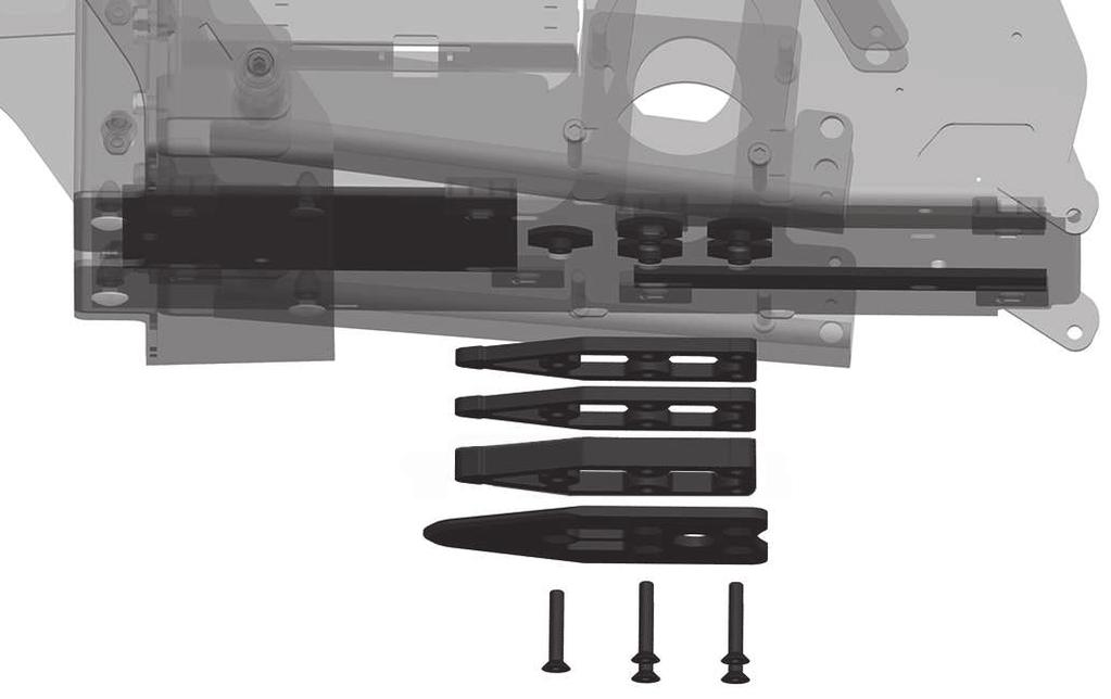
7 Sicherheit 4 Sicherheit 4.1 Bedeutung der Warnsymbolik WARNUNG VORSICHT HINWEIS Warnung vor möglichen schweren Unfall- und Verletzungsgefahren. Warnung vor möglichen Unfall- und Verletzungsgefahren. Warnung vor möglichen technischen Schäden. 4.2 Sicherheitshinweise zur Montage WARNUNG Unkontrollierte Bewegungen von Bauteilen bei Einstellarbeiten Quetschen, Klemmen, Stoßen durch Nichtbeachten von Wartungs- und Reparaturhinweisen Achten Sie darauf, dass sich niemals Körperteile, z. B. Hände oder Kopf, im Gefahrenbereich befinden. Führen Sie die Arbeiten mit sichernder Unterstützung eines Helfers durch. VORSICHT Unsachgemäße Hebearbeiten Quetschen, Klemmen, Stoßen durch Nichtbeachten von Sicherheitshinweisen Einige Teile des Elektrorollstuhls haben ein hohes Gewicht, z. B. Batterien, Rahmen, Sitz, Motoren. Achten Sie auf ein ergonomisch korrektes Anheben dieser Teile. Verwenden Sie ausreichend dimensionierte Hebezeuge oder führen Sie diese Arbeiten mit sichernder Unterstützung eines Helfers durch. Sind Arbeiten unter angehobenen Teilen oder Arbeitseinrichtungen erforderlich, sichern Sie diese mit geeigneten Einrichtungen gegen Lösen, Verlagern oder Herabfallen. Achten Sie beim Benutzen von Hebebühnen darauf, dass der Elektrorollstuhl mittig auf der Hubfläche steht und keine Teile in den Gefahrenbereich ragen. HINWEIS Unsachgemäße Vorbereitung der Einstellarbeiten Beschädigung des Produkts durch Herunterfallen und Nichtbeachten von Einstellhinweisen Sichern Sie das Produkt bei allen Arbeiten vor Umfallen oder Herunterfallen. Schalten Sie für alle Einstellarbeiten den Elektrorollstuhl aus und deaktivieren Sie die Sicherung. Davon ausgenommen sind die Funktionsprüfungen an den elektrischen Komponenten. Sorgen Sie vor allen Arbeiten am Sitz für ausreichenden Schutz des Polsters gegenüber mechanischen, chemischen und thermischen Belastungen. 5 Anlieferung 5.1 Lieferumfang Zum Lieferumfang von Ottobock gehören: Ottobock Montageset "Dahl Docking-System" (siehe Abb. 1) Bestellnummer 490E75=1_C: 491S75=ST610 (Standardsitz); 491S75=ST615 (VAS-Sitz) Pos. Artikelbezeichnung Anzahl 1 Schutzpolster (für VAS-Sitz) 2 2 Klettstreifen, selbstklebend (für VAS-Sitz) 2 3 Kantenschutz (für Standardsitz) 2 4 Längsstrebe zur Batteriebefestigung (inkl. Befestigungsmaterial) 1 Folgende Teile werden von der Firma Dahl benötigt: Adaptionsset der Firma Dahl für 490E75=1_C/Ottobock* (siehe Abb. 2, links) Bestellnummer * Pos. Artikelbezeichnung Anzahl 7
8 Herstellung der Gebrauchsfähigkeit Pos. Artikelbezeichnung Anzahl 1 Zwischenstück, 2 mm 2 2 Sechskantmutter M8 5 3 Distanzstreifen, PVC, 3 mm 2 4 Distanzplatte, PVC, 3 mm 1 Teile aus Basis Kit der Firma Dahl* (siehe Abb. 2, rechts) Bestellnummer * Pos. Artikelbezeichnung Anzahl 3 Verriegelungsplatte (500561*) 1 4 Zwischenstück, 8 mm (500673*) 1 5 Befestigungsschrauben M8x45, Torx (502800*) 5 * Aufgeführte Bestellnummern der Firma Dahl. Bestellung über: Dahl Engineering ApS Løvevej 3 DK-7700 Thisted Dänemark Telefon: sales@dahlengineering.dk 6 Herstellung der Gebrauchsfähigkeit 6.1 Benötigte Werkzeuge Für Einstell- und Wartungsarbeiten werden folgende Werkzeuge benötigt: INFORMATION Die nachfolgende Liste enthält nur Werkzeuge, die für den unmittelbaren Anbau der im Lieferumfang genannten Teile von Dahl und Ottobock erforderlich sind. Hinweise zu Werkzeugen für vorbereitende Arbeiten (z. B. zum Ausbau der Batterien) entnehmen Sie bitte der Service-Anleitung. Innensechskantschlüssel, Größe 4 Ring- und Maulschlüssel, Größe 8, 24 Drehmomentschlüssel (Messbereiche 5 50 Nm) Torx-Schraubendreher, Größe T45 Metallsäge Schere oder Cuttermesser Flüssige Gewindesicherung "mittelfest" (z. B. Loctite 241) 6.2 Montage Sicherheitshinweise zur Montage der Dahl-Teile am Ottobock Elektrorollstuhl WARNUNG Nichtbeachtung der Benutzerhinweise der Firma Dahl Schwere Verletzungen bei Unfällen durch Montagefehler Bei allen Montagearbeiten sind die Montage- und Sicherheitshinweise der Firma Dahl zu beachten, die in der Montage- und Bedienungsanleitung für das Dahl Docking-System enthalten sind. Die nachfolgenden Montagehinweise sind nur im Zusammenhang mit der Montage- und Bedienungsanleitung der Firma Dahl gültig. VORSICHT Falsche Verwendung der Befestigungsschrauben Schwere Verletzungen durch Bruch der Torx-Befestigungsschrauben Verwenden Sie nur die von Dahl Engineering mitgelieferten Torx-Befestigungsschrauben. Andere Standardschrauben sind nicht stark genug, um die Befestigungsplatte im Falle einer Kollision zu halten. Beachten Sie, dass die Torx-Befestigungsschrauben während der Montage gekürzt werden müssen. Beschädigen Sie beim Kürzen nicht das Gewinde. Beachten Sie, dass die Torx-Befestigungsschrauben während der Montage mit flüssiger Gewindesicherung mittelfest (z. B. Loctite 241) gesichert werden müssen. 8
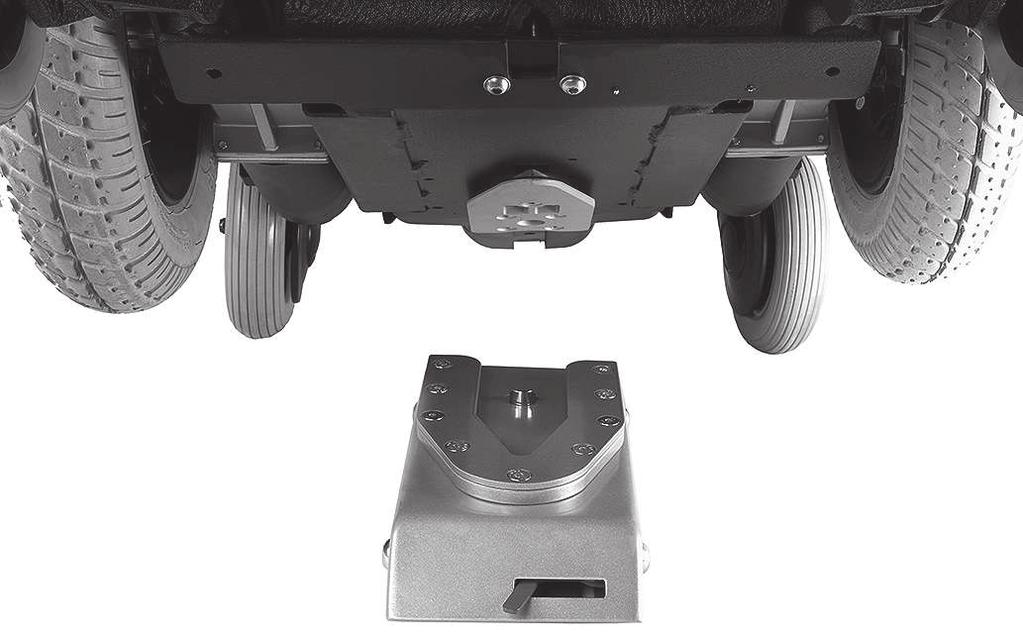
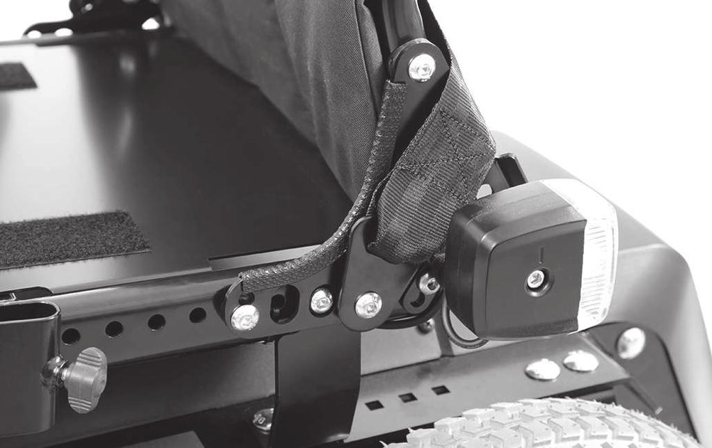
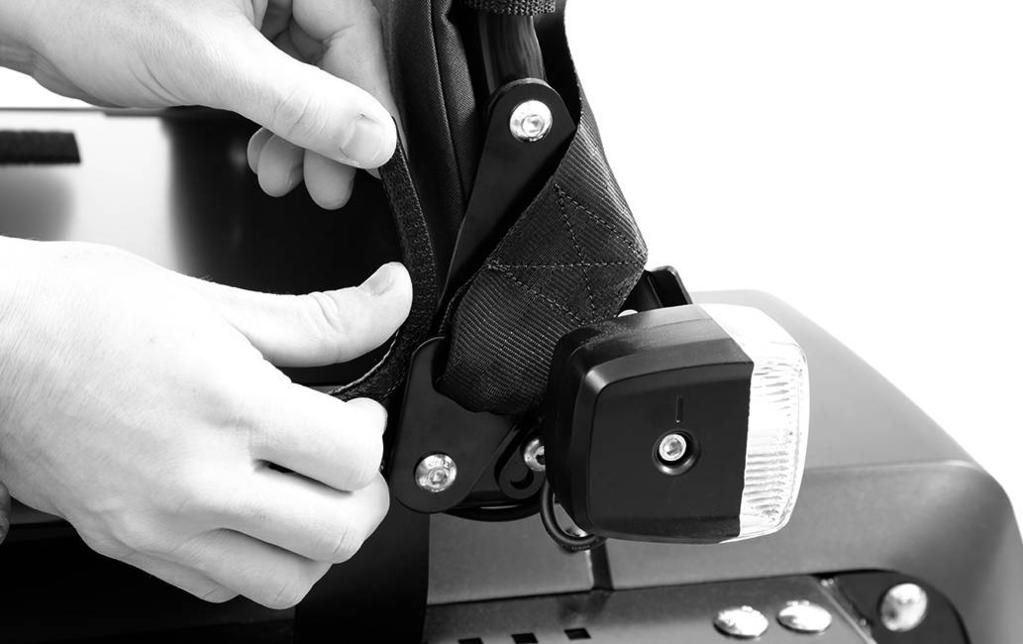
9 Herstellung der Gebrauchsfähigkeit INFORMATION Beachten Sie, dass sich die nachfolgenden Handlungsschritte zum Teil auf Handlungsanweisungen in der Service-Anleitung beziehen. Das PDF der Service-Anleitung erhalten Sie beim Customer Care Center (CCC) unter oder beim Service des Herstellers (Adressen siehe hintere Umschlaginnenseite oder Rückseite). Legen Sie sich vor Beginn der Montagearbeiten die Service-Anleitung bereit: Service-Anleitung für 490E75=1_C; 490E75=1_Z: 647G1999 Montage der Befestigungsplatte von Dahl am Antriebsträger 1) Die Zugänglichkeit zum Antriebsträger vorbereiten: Bei Ausstattung ohne elektrische Sitzfunktionen: Das Sitzkissen entnehmen und die Sitzplatte ausbauen. Bei Ausstattung mit elektrischen Sitzfunktionen: Den Sitz so weit wie möglich von der Batterieabdeckung wegfahren. 2) Die Steuerung ausschalten und die Hauptsicherung entnehmen. 3) Den Elektrorollstuhl etwas aufbocken (siehe Service-Anleitung). 4) Die Batterieabdeckung öffnen (siehe Service-Anleitung). Die Quer- und die Längsstrebe demontieren (siehe Service-Anleitung). INFORMATION: Beachten Sie, dass zum Abschluss der Arbeiten die Längsstrebe gegen die neu gelieferte Längsstrebe aus dem Ottobock Montageset für das Dahl Docking-System getauscht werden muss. 5) Die Batterien entnehmen (siehe Gebrauchsanweisung Fachpersonal oder Service-Anleitung). Der Boden des Antriebsträgers ist nun frei zugänglich. 6) Die Distanzstreifen gemäß Abbildung auf den Boden des Antriebsträgers legen (siehe Abb. 3, Pos. 1). 7) Die Distanzplatte gemäß Abbildung auf den Boden des Antriebsträgers legen (siehe Abb. 3, Pos. 2). 8) Die 5 Sechskantschrauben für die spätere Montage bereitlegen ((siehe Abb. 3, Pos. 3). 9) Die Verriegelungsplatte (siehe Abb. 4, Pos. 1) und die 3 dazu passenden Zwischenstücke (siehe Abb. 4, Pos. 2) bereitlegen. Dazu die 5 Torx-Befestigungschrauben bereitlegen (siehe Abb. 4, Pos. 3). 10) Die Torx-Befestigungsschrauben nacheinander von unten durch die Verriegelungsplatte, die 3 Zwischenstücke und durch die 5 Bohrungen des Antriebsträgers stecken (siehe Abb. 5). 11) Die Torx-Befestigungsschrauben (siehe Abb. 4, Pos. 3) von oben mit den 5 Sechskantmuttern am Antriebsträger vorläufig festschrauben (siehe Abb. 4, Pos. 4). 12) Den Überstand markieren. Die Schrauben entnehmen, kürzen und die Oberseite vorsichtig entgraten. WARNUNG! Die Schrauben müssen plan mit den Sechskantmuttern abschließen. Sie dürfen weder über die Sechskantmuttern hinausragen noch zu kurz sein, um die volle Haltekraft zu erzielen. 13) Die Torx-Befestigungsschrauben von unten wieder einstecken und mit flüssiger Gewindesicherung mittelfest (z. B. Loctite 241) sichern. 14) Die 5 Sechskantmuttern von oben auf die Torx-Befestigungsschrauben aufschrauben und mit 18 Nm anziehen (siehe Abb. 4, Pos. 3/4). 15) Die Batterien wieder einsetzen. Die Querstrebe montieren (siehe Service-Anleitung). 16) Die neue Längsstrebe montieren (siehe Abb. 6, Pos. 1). Dazu die Längsstrebe in die Querstrebe einhängen (siehe Abb. 6, Pos. 2) und die Längsstrebe mit Hilfe der Innensechskantschraube, der Unterlegscheibe und der Sechskantmutter am Antriebsträger montieren (siehe Abb. 6, Pos. 3). Die Unterlegscheibe und die Sechskantmutter befinden sich dabei innerhalb des Antriebsträgers. 17) Die Batterieabdeckung wieder schließen (siehe Service-Anleitung). Die Verriegelungsplatte des Dahl Docking-System ist unter dem Elektrorollstuhl montiert (siehe Abb. 7). Einstellen und Funktionskontrolle (siehe Abb. 8) Vor Verwendung der Verriegelungsplatte in der Dahl Docking Station ist eine Funktionskontrolle durchzuführen. Dabei ist zu prüfen, ob die Dahl Docking Station sicher verriegelt ist. Nähere Informationen enthält die Montageund Bedienungsanleitung des Herstellers Dahl. Montage der von Ottobock gelieferten Zusatzteile am VAS-Sitz (Schutzpolster) 1) Das Klettband zuschneiden. Die Länge so wählen, dass es den Platz zwischen Drehpunkt und Reflektor gut ausfüllt (siehe Abb. 9, Pos. 1). 2) Das Klettband auf die Abdeckung schräg unterhalb des Drehpunkts aufkleben. 3) Das Schutzpolster über die Abdeckung führen und am Klettband befestigen (siehe Abb. 10). 4) Das zweite Schutzpolster auf der anderen Seite in gleicher Weise befestigen. 9
10 Gebrauch Montage der von Ottobock gelieferten Zusatzteile am Standardsitz (Kantenschutz) 1) Den Kantenschutz bei Bedarf zuschneiden. Die Länge wird durch die Länge der Kante des Lagerschildes vorgegeben (siehe Abb. 11, Pfeil). 2) Den Kantenschutz an der Kante des Lagerschilds ansetzen und mit der Hand aufdrücken (siehe Abb. 12). 3) Den zweiten Kantenschutz auf der anderen Seite in gleicher Weise befestigen. 7 Gebrauch 7.1 Vorgeschriebene Verwendung von Kopfstützen WARNUNG Nichtbeachtung der Benutzerhinweise von Ottobock Schwere Verletzungen bei Unfällen durch Anwenderfehler Bei Verwendung des Dahl Docking-Systems mit freigegebenen Elektrorollstühlen von Ottobock ist zwingend das Anbringen einer Kopfstütze von Ottobock erforderlich, die für die Nutzung in Verbindung mit dem Dahl Docking System freigegeben ist. Beachten Sie die nachfolgende Liste der möglichen Kopfstützen. Folgende Kopfstützen sind für die Nutzung in Verbindung mit dem Dahl Docking-System freigegeben: Code-Nummer Beschreibung Artikelnummer EL006 Kopfstütze, klein 430H1=3-7 EL007 Kopfstütze, groß 430H1=1-7 EL009 Kopfstütze, konkav, Größe M 476L49=SK002 EL011 Kopfstütze mit ABS-Außenschale, klein 430H2=3-7 EL012 Kopfstütze mit ABS-Außenschale, groß 430H2=1-7 EL013 Kopf-/Nackenstütze, klein 430C1=3-7 EL014 Kopf-/Nackenstütze, groß 430C1=1-7 EL015 Kopf-/Nackenstütze, X-Form, klein 430C4=1-7 EL016 Kopf-/Nackenstütze, X-Form, groß 430C3=1-7 EL017 Kopfstütze, konkav, verstellbar, Einheitsgröße 476L49=SK020 EL020 Kopfstütze, 3-teilig, winkelverstellbar, Größe L 476L49=SK Verwenden in Kraftfahrzeugen zur Beförderung mobilitätsbehinderter Personen (KMP) WARNUNG Nichtbeachtung der Benutzerhinweise der Firma Dahl Schwere Verletzungen bei Unfällen durch Anwenderfehler Lesen Sie vor Verwendung des Dahl Docking-Systems in Kraftfahrzeugen zur Beförderung mobilitätsbehinderter Personen (KMP) die Montage- und Bedienungsanleitung und insbesondere die Sicherheitshinweise des Herstellers. Verwenden Sie das Dahl Docking-System nur dann, wenn die von Ottobock gelieferten Zusatzteile (Schutzpolster, Kantenschutz) am Elektrorollstuhl montiert sind. Andernfalls könnten die Gurte des Personenrückhaltesystems beschädigt und in ihrer Funktion beeinträchtigt werden. WARNUNG Positionieren in Kraftfahrzeugen zur Beförderung mobilitätsbehinderter Personen (KMP) Schwere Verletzungen bei Unfällen durch Anwenderfehler Die Positionierung des Produkts im KMP darf nur durch qualifiziertes Fachpersonal erfolgen. Das Produkt ist immer nach vorn zu richten, wenn es als Sitz in einem KMP verwendet wird. Beachten Sie die Positionierungshinweise in der mitgelieferten Bedienungsanleitung des Herstellers DAHL. 10
11 Wartung und Reparatur WARNUNG Verbotene Anwendung des Gurtsystems als Personenrückhaltesystem in KMP Schwere Verletzungen durch Fehler im Umgang mit dem Produkt Verwenden Sie die mit dem Produkt angebotenen Gurte und Positionierungshilfen keinesfalls als Teil eines Personenrückhaltesystems beim Transport in KMP. Beachten Sie, dass die mit dem Produkt angebotenen Gurte und Positionierungshilfen nur als zusätzliche Stabilisierung der sitzenden Person im Produkt dienen. WARNUNG Verwenden des Produkts mit bestimmten Einstellungen bzw. angebauten Optionen Schwere Verletzungen bei Unfällen durch sich lösende Optionen Entfernen Sie vor der Benutzung des Produkts als Sitz in KMP die Optionen, die für einen sicheren Transport in KMP abgebaut werden müssen. Beachten Sie die Angaben in der Gebrauchsanweisung zum Hauptprodukt. Verstauen Sie die abgebauten Optionen sicher im KMP. Vor Verwendung der Option "Dahl Docking-System" in einem KMP-Fahrzeug ist sicherzustellen, dass die von Ottobock gelieferten Schutzhilfen am Sitz des Elektrorollstuhls befestigt sind (Schutzpolster für VAS-Sitz: siehe Abb. 10; Kantenschutz für Standardsitz: siehe Abb. 11). Nur so ist gewährleistet, dass die Personenrückhaltegurte bei einem Zusammenstoß nicht von scharfen Kanten beschädigt werden. Für die Benutzung des Elektrorollstuhls sind zusätzlich die Hinweise in der Gebrauchsanweisung zum Hauptprodukt von Ottobock zu beachten, insbesondere das Kapitel "Verwenden in Kraftfahrzeugen zur Beförderung mobilitätsbehinderter Personen (KMP)". Verweis auf Dokumente der Firma Dahl Für die Benutzung des Dahl Docking Systems im KMP-Fahrzeug sind die Bedienungshinweise in der Montageund Bedienungsanleitung des Herstellers Dahl zu beachten. Die gilt insbesondere für folgende Inhalte: Befestigung des Rollstuhls in der Docking-Station Lösen von der Docking-Station 7.3 Reinigung Reinigung der von Ottobock gelieferten Zusatzteile (Schutzpolster, Kantenschutz) Die Polster können bis max. 60 C (140 F) mit einem milden Reinigungsmittel in einer Waschmaschine gewaschen werden. Den Klettverschluss mit einer trockenen Bürste reinigen. Vor Verwendung das Produkt an der Luft vollständig trocknen lassen. Das Produkt keiner direkten Hitzeeinwirkung aussetzen (z. B. Sonnenbestrahlung, Ofen- oder Heizkörperhitze, Haartrockner). Reinigung der Teile des Dahl Docking-Systems Für die Reinigung der Teile des Dahl Docking-Systems sind die Hinweise in der Bedienungsanleitung des Herstellers Dahl zu beachten. 8 Wartung und Reparatur 8.1 Wartung Wartungshinweise zu den von Ottobock gelieferten Zusatzteilen (Schutzpolster, Kantenschutz) Bei regelmäßiger Reinigung ist keine Wartung erforderlich. Wartungshinweise zur Option "Dahl Docking-System" Für eine korrekte Wartung sind die Hinweise in der Bedienungsanleitung des Herstellers Dahl zu beachten. Die Funktionsfähigkeit des Produkts vor jedem Einsatz überprüfen. Bei festgestellten Mängeln darf das Produkt nicht verwendet werden. Dies gilt insbesondere bei Instabilität des Produkts oder geändertem Fahrverhalten sowie bei Problemen mit der Sitzposition des Benutzers oder der Stabilität des Sitzes. Um die Mängel zu beheben ist umgehend das Fachpersonal zu informieren. Gleiches gilt, wenn lockere, verschlissene, verbogene oder beschädigte Teile, Rahmenrisse oder Rahmenbrüche bemerkt werden. 11
12 Entsorgung Unterbleibt die Wartung des Produkts, kann dies zu Verletzungsgefahren für den Benutzer des Produkts führen. 8.2 Reparatur Reparaturhinweise zu den von Ottobock gelieferten Zusatzteilen (Schutzpolster, Kantenschutz) Im Schadensfall ist umgehend der Service von Ottobock zu kontaktieren (Adresse siehe hintere Umschlaginnenseite oder Rückseite). Reparaturhinweise zur Option "Dahl Docking-System" Im Schadensfall ist umgehend das Fachpersonal zu kontaktieren, das dass Produkt angepasst hat oder der Service des Herstellers (Adresse siehe die beiliegende Bedienungsanleitung des Herstellers Dahl). 9 Entsorgung 9.1 Hinweise zur Entsorgung Das Produkt ist zur Entsorgung an den Fachhändler zurückzugeben. Alle Komponenten des Produkts sind gemäß den jeweiligen landesspezifisch geltenden Umweltschutzbestimmungen zu entsorgen. 10 Rechtliche Hinweise Alle rechtlichen Bedingungen unterliegen dem jeweiligen Landesrecht des Verwenderlandes und können dementsprechend variieren Haftung Der Hersteller haftet, wenn das Produkt gemäß den Beschreibungen und Anweisungen in diesem Dokument verwendet wird. Für Schäden, die durch Nichtbeachtung dieses Dokuments, insbesondere durch unsachgemäße Verwendung oder unerlaubte Veränderung des Produkts verursacht werden, haftet der Hersteller nicht Garantie Nähere Informationen zu den Garantiebedingungen erteilt das Fachpersonal, das dieses Produkt angepasst hat oder der Service des Herstellers (Adressen siehe hintere Umschlaginnenseite). 12
13 Table of contents Table of contents 1 Foreword Product description Intended use Area of application Qualification Safety Explanation of warning symbols Safety Instructions for Assembly Delivery Scope of delivery Preparation for use Required tools Installation Use Prescribed use of head supports Use in vehicles for transporting persons with reduced mobility Cleaning Maintenance and repair Maintenance Repair Disposal Disposal information Legal information Liability Warranty
14 Foreword 1 Foreword INFORMATION Last update: Please read this document carefully before using the product. Follow the safety instructions to avoid injuries and damage to the product. Instruct the user in the proper and safe use of the product. Please keep this document in a safe place. INFORMATION New information regarding product safety and product recalls can be obtained from the Customer Care Center (CCC) at oa@ottobock.com or from the manufacturer s service department (see inside back cover or back page for addresses). You can request this document as a PDF file from the Customer Care Center (CCC) at oa@ottobock.com or from the manufacturer s service department (see inside back cover or back page for addresses). It is possible to increase the display size of the PDF document. These instructions for use provide you with important information on the installation of attachments (protective pads, edge protection, longitudinal bracing for battery mounting), which are required for the use of the "Dahl docking system" option on approved Ottobock power wheelchairs. They also describe the installation of the locking plate, which is provided by Dahl as a part of the "Dahl docking system" option, on approved Ottobock power wheelchairs. Please note the following: Ottobock only provides the attachments required for the use of the Dahl docking system. These are part of the Ottobock installation kit for the "Dahl docking system" option (see Page 15). There, information is also provided on the parts required from Dahl and where these can be ordered. Please read these instructions for use prior to installation. The user must also read the instructions before using the system. These instructions for use must be issued to the user and stored in an easy to reach location in the vehicle. 2 Product description Information on the function of the attachments supplied by Ottobock (protective pads, edge protection) The attachments supplied by Ottobock must be installed and used prior to the use of the Dahl docking system, otherwise the belts of the occupant restraint system could become damaged and their function could be adversely affected. The attachments supplied reduce the mechanical forces which act on the belt system of the occupant restraint system. Information on the function of the "Dahl docking system" option The Dahl docking system makes it possible to attach wheelchairs to the floor of a vehicle (e.g. in vehicles for transporting persons with reduced mobility). For this purpose, the locking plate supplied by Dahl must first be installed under the wheelchair (see the section "Installation"). When the wheelchair is driven to the docking station, it is then attached to the floor of the vehicle using the locking plate. For more detailed information on the overall function of the Dahl docking system, please consult the operating instructions provided by Dahl. 3 Intended use 3.1 Area of application The "Dahl docking system" option in conjunction with the attachments supplied by Ottobock was tested in accordance with the ISO standard. It is currently approved for the following Ottobock products: 490E75=1_C 3.2 Qualification The installation and adjustments described below may only be carried out by qualified personnel. 14
15 Safety 4 Safety 4.1 Explanation of warning symbols WARNING CAUTION NOTICE Warning regarding possible serious risks of accident or injury. Warning regarding possible risks of accident or injury. Warning regarding possible technical damage. 4.2 Safety Instructions for Assembly WARNING Uncontrolled movement of components when making adjustments Crushing, pinching, blows due to non-observance of the maintenance and repair instructions Ensure that body parts, such as hands or head, are never in the danger zone. Perform the work with the aid of a helper for support. CAUTION Improper lifting Crushing, pinching, blows due to failure to observe safety instructions Some parts of the power wheelchair, such as the batteries, frame, seat, and motors, are very heavy. Ensure ergonomically correct lifting of these parts. Use sufficiently large hoisting devices or perform this work with a helper. If it is necessary to work underneath raised parts or equipment, make sure these are secured by suitable means so that they cannot come loose, shift, or fall down. When using lifting platforms, ensure that the power wheelchair is centred on the platform and that no parts protrude into the danger zone. NOTICE Improper preparation before making adjustments Damage to the product due to falling down and failure to follow setting instructions When you work on the product, secure it so that it cannot tip over or fall down. Turn the power wheelchair off and deactivate the circuit breaker before making any adjustments. Functional tests of the electrical components are excepted from this rule. Before performing any work on the seat, ensure that the cushion is sufficiently protected against mechanical, chemical, and thermal effects. 5 Delivery 5.1 Scope of delivery The Ottobock scope of delivery includes: Ottobock installation kit for the "Dahl docking system" (see fig. 1) Order number 490E75=1_C: 491S75=ST610 (standard seat); 491S75=ST615 (VAS seat) Item Article designation Quantity 1 Protective pads (for VAS seat) 2 2 Hook-and-loop strips, self-adhesive (for VAS seat) 2 3 Edge protection (for standard seat) 2 4 Longitudinal bracing for battery mounting (including mounting materials) 1 The following parts are required from Dahl: Adaption set supplied by Dahl for 490E75=1_C/Ottobock* (see fig. 2, left) Order number * Item Article designation Quantity 15
16 Preparation for use Item Article designation Quantity 1 Intermediate piece, 2 mm 2 2 M8 hexagon nut 5 3 Spacer strip, PVC, 3 mm 2 4 Spacer plate, PVC, 3 mm 1 Parts from the basic kit supplied by Dahl (see fig. 2, right) Order number * Item Article designation Quantity 5 Locking plate (500561*) 1 6 Intermediate piece, 8 mm (500673*) 1 7 Mounting screws M8x45, Torx (502800*) 5 * Listed Dahl order number. Order via: Dahl Engineering ApS Løvevej 3 DK-7700 Thisted Denmark Tel: sales@dahlengineering.dk 6 Preparation for use 6.1 Required tools The following tools are required for adjustments and maintenance work: INFORMATION The following list only includes tools which are required for the direct assembly of the parts specified in the scope of supply of Dahl and Ottobock. Please refer to the service manual for information on tools for preparatory work (e.g. for the removal of the battery). Allen keys, size 4 Ring and open-ended spanner, size 8, 24 Torque wrench (measurement ranges 5-50 Nm) Torx screwdriver, size T45 Metal saw Scissors or cutter knife Liquid thread lock, "medium strength" (e.g. Loctite 241) 6.2 Installation Safety instructions for the installation of the Dahl parts on the Ottobock power wheelchair WARNING Non-observance of the Dahl user guide Severe injury in case of accidents due to installation errors The installation and safety instructions supplied by Dahl, which are included with the installation and operating instructions for the Dahl docking system, must be observed during all installation work. The following installation notes are only valid in conjunction with the installation and operating instructions supplied by Dahl. CAUTION Incorrect use of mounting screws Severe injuries due to breakage of the Torx mounting screws Only use the Torx mounting screws supplied by Dahl Engineering. Other standard screws are not strong enough to hold the attachment plate in case of a collision. Please note that the Torx mounting screws have to be shortened during installation. Do not damage the thread when shortening the screws. Please note that the Torx mounting screws have to be secured with "medium strength" liquid thread lock (e.g. Loctite 241) during installation. 16
17 Preparation for use INFORMATION Please note that the following steps refer in part to instructions in the service manual. You can request the PDF file of the service manual from the Customer Care Center (CCC) at or from the manufacturer s service department (see inside back cover or back page for addresses). Before starting the installation work, ensure that the service manual is available: Service manual for 490E75=1_C; 490E75=1_Z: 647G1999 Installation of the Dahl attachment plate on the drive support 1) Prepare access to the drive support: In the equipment version without power seat functions: Remove the seat cushion and disassemble the seat plate. In the equipment version with power seat functions: Move the seat away from the battery cover as far as possible. 2) Switch off the control device and remove the main fuse. 3) Slightly jack up the power wheelchair (see service manual). 4) Open the battery cover (see service manual). Disassemble the transverse and longitudinal bracing (see service manual). INFORMATION: Please note that, to complete the work, the longitudinal bracing has to be replaced with the newly supplied longitudinal bracing from the Ottobock installation kit for the Dahl docking system. 5) Remove the batteries (see instructions for use for qualified personnel or service manual). The floor of the drive support is now freely accessible. 6) Place the spacer strips on the floor of the drive support in accordance with the illustration (see fig. 3, item 1). 7) Place the spacer plate on the floor of the drive support in accordance with the illustration (see fig. 3, item 2). 8) Have the 5 hexagon screws ready for installation at a later stage (see fig. 3, item 3). 9) Have the locking plate (see fig. 4, item 1) and the 3 matching intermediate pieces (see fig. 4, item 2) ready. Also have the 5 Torx mounting screws ready for this purpose (see fig. 4, item 3). 10) Insert the Torx mounting screws one after the other from the bottom through the locking plate, the 3 intermediate pieces and the 5 holes of the drive support (see fig. 5). 11) Provisionally screw on the Torx mounting screws (see fig. 4, item 3) to the drive support from the top, using the 5 hexagon nuts (see fig. 4, item 4). 12) Mark the excess. Remove the screws, shorten them and carefully deburr the top. WARNING! The screws must be flush with the hexagon nut. They may neither protrude beyond the hexagon nuts or be too short to achieve their full holding force. 13) Re-insert the Torx mounting screws from the bottom and secure them with "medium strength" liquid thread lock (e.g. Loctite 241). 14) Screw on the 5 hexagon nuts onto the Torx mounting screws from the top and tighten with 18 Nm (see fig. 4, item 3/4). 15) Re-insert the batteries. Install the transverse bracing (see service manual). 16) Install the new longitudinal bracing (see fig. 6, item 1). To do so, fit the longitudinal bracing in the transverse bracing (see fig. 6, item 2) and mount the longitudinal bracing on the drive support using the hexagon socket screw, the washer and the hexagon nut (see fig. 6, item 3). The washer and the hexagon nut are positioned inside the drive support. 17) Close the battery cover again (see service manual). The locking plate of the Dahl docking system is installed under the power wheelchair (see fig. 7). Installation of the attachments supplied by Ottobock on the VAS seat (protective pads) 1) Cut the hook-and-loop strap to size. Select the length so that the space between the pivot point and the reflector is well filled (see fig. 9, item 1). 2) Stick the hook-and-loop strap to the cover diagonally below the pivot point. 3) Guide the protective pad over the cover and attach it to the hook-and-loop strap (see fig. 10). 4) Attach the second protective pad on the other side in the same way. Installation of the attachments supplied by Ottobock on the standard seat (edge protection) 1) Cut the edge protection to size if required. The length is prescribed by the length of the edge of the end plate (see fig. 11, arrow). 2) Position the edge protection on the edge of the end plate and press it on by hand (see fig. 12). 17
18 Use 3) Attach the second edge protection on the other side in the same way. 7 Use 7.1 Prescribed use of head supports WARNING Non-observance of the Ottobock user guide Serious injuries in case of accidents due to user error When using the Dahl docking system with approved Ottobock power wheelchairs, the installation of an Ottobock head support approved for use in combination with the Dahl docking system is mandatory. Note the list of possible head supports below. The following head supports are approved for use in connection with the Dahl docking system: Code number Description Article number EL006 Head support, small 430H1=3-7 EL007 Head support, large 430H1=1-7 EL009 Head support, concave, size M 476L49=SK002 EL011 Head support with ABS exterior shell, small 430H2=3-7 EL012 Head support with ABS exterior shell, large 430H2=1-7 EL013 Head/neck support, small 430C1=3-7 EL014 Head/neck support, large 430C1=1-7 EL015 Head/neck support, X-shape, small 430C4=1-7 EL016 Head/neck support, X-shape, large 430C3=1-7 EL017 Head support, concave, adjustable, one size only 476L49=SK020 EL020 Head support, 3-piece, angle-adjustable, size L 476L49=SK Use in vehicles for transporting persons with reduced mobility WARNING Non-observance of the Dahl user guide Serious injuries in case of accidents due to user error Before using the Dahl docking system in vehicles for transporting persons with reduced mobility, read the installation and operating instructions and in particular the safety notices of the manufacturer. Only use the Dahl docking system if the attachments supplied by Ottobock (protective pads, edge protection) are installed on the power wheelchair. Otherwise the belts of the occupant restraint system could become damaged and their function could be adversely affected. WARNING Positioning in vehicles for transporting persons with reduced mobility Serious injuries in case of accidents due to user error The positioning of the product in vehicles for transporting persons with reduced mobility may only be performed by qualified personnel. The product must always face forwards when it is used as a seat in a vehicle for transporting persons with reduced mobility. Please observe the positioning information in the instructions for use supplied by the manufacturer Dahl. WARNING Use of the belt system as a passenger restraint system in vehicles for transporting persons with reduced mobility is forbidden Serious injuries due to improper handling of the product Under no circumstances may the belts and positioning aids offered with the product be used as part of a passenger restraint system in vehicles for transporting persons with reduced mobility. Note that the belts and positioning aids offered with the product are only intended to help support the user sitting in the product. 18
19 Maintenance and repair WARNING Using the product with certain settings and/or installed accessories Severe injury in case of accidents due to accessories coming loose Before using the product as a seat in a vehicle for transporting persons with reduced mobility, remove accessories that need to be dismantled for safe transportation in a vehicle for transporting persons with reduced mobility. Observe the information on the main product in the instructions for use. Stow all dismantled accessories securely in the vehicle for transporting persons with reduced mobility. Prior to the use of the "Dahl docking system" in a vehicle for transporting persons with reduced mobility, it must be ensured that the protective aids supplied by Ottobock are attached to the seat of the power wheelchair (protective pads for VAS seat: see fig. 10; edge protection for standard seat: see fig. 11). This is the only way to ensure that the occupant restraint belts are not damaged by sharp corners in case of a crash. For the use of the power wheelchair, attention must also be paid to the information provided in the instructions for use for the main Ottobock product, in particular the section "Use in vehicles for transporting persons with reduced mobility". For the use of the Dahl docking system in vehicles for transporting persons with reduced mobility, attention must be paid to the instructions for use in the operating instructions by the manufacturer, Dahl. This applies in particular to the following contents: Attachment of the wheelchair in the docking station Release from the docking station 7.3 Cleaning Cleaning the attachments supplied by Ottobock (protective pads, edge protection) The pads can be machine-washed in warm water up to max. 60 C (140 F), using a mild detergent. Clean the hook-and-loop closure with a dry brush. Allow the product to fully air dry before use. Do not expose the product to direct heat (e.g. sunshine, stove or radiator heat, hair dryer). Cleaning the parts of the Dahl docking system For cleaning the parts of the Dahl docking system, attention must be paid to the information in the operating instructions by the manufacturer, Dahl. 8 Maintenance and repair 8.1 Maintenance Maintenance instructions for the attachments supplied by Ottobock (protective pads, edge protection) Maintenance is not required if the attachments are cleaned regularly. Maintenance instructions for the "Dahl docking system" option For correct maintenance, attention must be paid to the information in the operating instructions by the manufacturer, Dahl. The function of the product should be checked before each use. The product may not be used if defects are noted. This applies in particular in case of instability of the product or altered driving characteristics as well as problems with the user's seating position or the stability of the seat. Inform the qualified personnel promptly for the rectification of defects. This also applies if loose, worn, bent or damaged components, cracks in the frame or broken frame components are identified. Failure to maintain the product can lead to injuries for the user of the product. 8.2 Repair Repair instructions for the attachments supplied by Ottobock (protective pads, edge protection) In case of damage, promptly contact the Ottobock service department (see inside back cover or back page for the address). Repair instructions for the "Dahl docking system" option In case of damage, promptly contact the qualified personnel who adapted the product or the manufacturer's service department (for the address, see the enclosed operating instructions of the manufacturer, Dahl). 19
20 Disposal 9 Disposal 9.1 Disposal information Return the product to the specialist dealer for disposal. All components of the product must be disposed of properly in accordance with the respective national environmental regulations. 10 Legal information All legal conditions are subject to the respective national laws of the country of use and may vary accordingly Liability The manufacturer will only assume liability if the product is used in accordance with the descriptions and instructions provided in this document. The manufacturer will not assume liability for damage caused by disregarding the information in this document, particularly due to improper use or unauthorised modification of the product Warranty Further information on the warranty terms and conditions can be obtained from the qualified personnel that has fitted this product or the manufacturer's service (see inside back cover for addresses). 20
21 Sommaire Sommaire 1 Avant-propos Description du produit Utilisation conforme Domaine d application Qualification Sécurité Signification des symboles de mise en garde Consignes de sécurité relatives au montage Livraison Contenu de la livraison Préparation à l utilisation Outils nécessaires Montage Utilisation Utilisation prescrite des appuie-têtes Utilisation dans des véhicules adaptés au transport de personnes à mobilité réduite (TPMR) Nettoyage Maintenance et réparations Maintenance Réparation Mise au rebut Consignes relatives à la mise au rebut Informations légales Responsabilité Garantie commerciale
22 Avant-propos 1 Avant-propos INFORMATION Date de la dernière mise à jour : Veuillez lire attentivement l intégralité de ce document avant d utiliser le produit. Respectez les consignes de sécurité afin d éviter toute blessure et endommagement du produit. Apprenez à l utilisateur à bien utiliser son produit et informez-le des consignes de sécurité. Conservez ce document. INFORMATION Vous trouverez de nouvelles informations sur la sécurité et les rappels du produit auprès du Customer Care Center (CCC) à oa@ottobock.com ou auprès du service après-vente du fabricant (voir adresses en 3ème ou 4ème de couverture). Vous pouvez commander le fichier PDF de ce document auprès du Customer Care Center (CCC) à oa@ottobock.com ou auprès du service après-vente du fabricant (voir adresses en 3ème ou 4ème de couverture). Le fichier PDF peut également s afficher dans un format agrandi. Les présentes instructions d utilisation vous fournissent d importantes indications sur le montage d éléments supplémentaires (rembourrages de protection, protection de bord, entretoise longitudinale pour la fixation des batteries) qui sont requis pour l utilisation de l option «Système d arrimage Dahl» sur des fauteuils roulants électriques autorisés d Ottobock. Elles décrivent de plus la manière dont la plaque de verrouillage proposée par la société Dahl est montée dans le cadre de l option «Système d arrimage Dahl» sur des fauteuils roulants électriques autorisés d Ottobock. Veuillez respecter les points suivants : Ottobock fournit uniquement les éléments supplémentaires requis pour l utilisation du système d arrimage Dahl. Ils font partie du kit de montage Ottobock pour l option «Système d arrimage Dahl» (consulter la page 23). Vous y apprendrez aussi quels éléments de la société Dahl sont requis et comment les commander. Veuillez prendre le temps de lire attentivement les présentes instructions d utilisation avant de commencer le montage. L utilisateur doit aussi prendre le temps de lire attentivement les instructions avant d utiliser le système. Remettez les présentes instructions d utilisation à l utilisateur, qui doit les conserver à un endroit facilement accessible dans le véhicule. 2 Description du produit Remarques sur le fonctionnement des éléments supplémentaires fournis par Ottobock (rembourrages de protection, protection de bord) Les éléments supplémentaires fournis par Ottobock doivent être montés et utilisés avant l utilisation du système d arrimage Dahl, faute de quoi les sangles du système de retenue des personnes risquent d être endommagées et leur fonctionnement est susceptible d être altéré. Les éléments supplémentaires fournis réduisent les contraintes mécaniques exercées sur le système de sangles du système de retenue des personnes. Remarques sur le fonctionnement de l option «Système d arrimage Dahl» Le système d arrimage Dahl permet de fixer des fauteuils roulants au plancher d un véhicule (p. ex. dans des véhicules destinés au transport de personnes à mobilité réduite). Il convient à cet effet de monter auparavant la plaque de verrouillage fournie par la société Dahl sous le fauteuil roulant (voir chap. «Montage»). Lorsque le fauteuil roulant est déplacé vers la station d arrimage, il se fixe alors à l aide de la plaque de verrouillage au plancher du véhicule. De plus amples informations au sujet du fonctionnement global du système d arrimage Dahl figurent dans les instructions d utilisation de la société Dahl. 3 Utilisation conforme 3.1 Domaine d application L option «Système d arrimage Dahl» combinée avec les éléments supplémentaires fournis par Ottobock a été évaluée conformément à la norme ISO Elle est actuellement autorisée pour les produits Ottobock suivants : 490E75=1_C 22
23 3.2 Qualification Seul un personnel spécialisé et qualifié est autorisé à effectuer les opérations de montage et de réglage décrites ci-après. 4 Sécurité 4.1 Signification des symboles de mise en garde AVIS AVERTISSEMENT PRUDENCE Mise en garde contre les éventuels risques d accidents et de blessures graves. Mise en garde contre les éventuels risques d accidents et de blessures. Mise en garde contre les éventuels dommages techniques. 4.2 Consignes de sécurité relatives au montage AVERTISSEMENT Déplacements incontrôlés des pièces pendant les opérations de réglage Pincement, écrasement et chocs dus au non-respect des consignes de maintenance et de réparation Veillez à ne jamais passer une partie de votre corps (mains ou tête par ex.) dans une zone dangereuse. Effectuez les opérations de réglage en vous faisant aider par une tierce personne. PRUDENCE Opérations de levage non conformes Pincement, écrasement et chocs dus au non-respect des consignes de sécurité Certains éléments du fauteuil roulant électrique tels que les batteries, le châssis, l assise et les moteurs présentent un poids important. Veillez à soulever ces éléments correctement d un point de vue ergonomique. Utilisez uniquement des outils de levage présentant des dimensions suffisantes ou effectuez ces opérations en vous faisant aider par une tierce personne. S il est nécessaire d effectuer des opérations au-dessous de pièces ou de dispositifs soulevés, fixez-les à l aide de systèmes adaptés afin qu ils ne se desserrent pas, ne se déplacent pas ou ne tombent pas. Veillez lors de l utilisation de plates-formes élévatrices à ce que le fauteuil roulant électrique se trouve au centre de la surface de levage et qu aucun élément ne dépasse dans la zone dangereuse. AVIS Sécurité Préparation non conforme des opérations de réglage Endommagement du produit provoqué par sa chute et le non-respect des consignes de réglage Lors de toute intervention sur le produit, il convient de s assurer qu il est bien calé afin d éviter un basculement ou une chute du produit. Mettez le fauteuil roulant électrique hors tension pour toutes les opérations de réglage et désactivez le fusible. Ceci ne s applique pas en cas de contrôles de fonctionnement des composants électriques. Avant de procéder à toute opération sur l assise, protégez suffisamment le rembourrage des contraintes mécaniques, chimiques et thermiques. 5 Livraison 5.1 Contenu de la livraison La livraison d Ottobock comprend : Kit de montage Ottobock du «système d arrimage Dahl» (voir ill. 1) Numéro de commande 490E75=1_C : 491S75=ST610 (siège standard) ; 491S75=ST615 (siège VAS) Pos. Désignation Nombre 1 Rembourrages de protection (pour siège VAS) 2 2 Bandes velcro, autocollantes (pour siège VAS) 2 3 Protection de bord (pour siège standard) 2 4 Entretoise longitudinale pour la fixation de batteries (y comp. matériel de fixation) 1 23
24 Préparation à l utilisation Les pièces suivantes de la société Dahl sont requises : Kit d adaptation de la société Dahl pour 490E75=1_C/Ottobock* (voir ill. 2, à gauche) Numéro de commande * Pos. Désignation Nombre 1 Adaptateur, 2 mm 2 2 Écrou hexagonal M8 5 3 Bandes d écartement, PVC, 3 mm 2 4 Plaque de séparation, PVC, 3 mm 1 Pièces du kit de base de la société Dahl* (voir ill. 2, à droite) Numéro de commande * Pos. Désignation Nombre 5 Plaque de verrouillage (500561*) 1 6 Adaptateur, 8 mm (500673*) 1 7 Vis de fixation M8x45, Torx (502800*) 5 * Numéros de commande de la société Dahl. Commande auprès de : Dahl Engineering ApS Løvevej 3 DK-7700 Thisted Danemark Téléphone : dahl@dahlengineering.dk 6 Préparation à l utilisation 6.1 Outils nécessaires Les outils suivants sont nécessaires pour les opérations de réglage et de maintenance : INFORMATION La liste suivante contient uniquement des outils requis pour le montage direct des éléments fournis par Dahl et Ottobock. Veuillez consulter la notice de maintenance pour obtenir des consignes relatives aux outils pour les travaux de préparation (p. ex. pour le démontage des batteries). Clé Allen de 4 Clé à œil et plate de 8 et 24 Clé dynamométrique (de 5 à 50 Nm) Tournevis Torx, T45 Scie à métaux Paire de ciseaux ou cutter Frein filet liquide de «force moyenne» (p. ex. Loctite 241) 6.2 Montage Consignes de sécurité relatives au montage des éléments Dahl sur le fauteuil roulant électrique Ottobock AVERTISSEMENT Non-respect des consignes d utilisation de la société Dahl Blessures graves en cas d accident provoqué par des erreurs de montage Lors de tous les travaux de montage, respectez les consignes de montage et de sécurité de la société Dahl, qui sont indiquées dans les instructions de montage et d utilisation du système d arrimage Dahl. Les consignes de montage suivantes sont uniquement valables avec les instructions de montage et d utilisation de la société Dahl. 24
Bedienungsanleitung SUNNYHEAT Standfuß (Art. Nr )
") Bedienungsanleitung SUNNYHEAT Standfuß (Art. Nr. 221012) Der SUNNYHEAT Standfuß ist zur Positionierung Ihres Heizpaneels auf dem Standfuß gedacht. Anwendung findet der Standfuß bei allen Paneelen außer
Bedienungsanleitung SUNNYHEAT Standfuß (Art. Nr. 221012) Der SUNNYHEAT Standfuß ist zur Positionierung Ihres Heizpaneels auf dem Standfuß gedacht. Anwendung findet der Standfuß bei allen Paneelen außer
Electrical tests on Bosch unit injectors
 Valid for Bosch unit injectors with order numbers 0 414 700 / 0 414 701 / 0 414 702 Parts Kit Magnet*: - F00H.N37.925 - F00H.N37.933 - F00H.N37.934 * For allocation to the 10-place Bosch order number,
Electrical testing of Bosch common rail piezo injectors
 Applies to generation CRI 3: Bosch 10-position order number 0 445 115 = CRI 3-16 (CRI 3.0) 1600 bar 0 445 116 = CRI 3-18 (CRI 3.2) 1800 bar 0 445 117 = CRI 3-20 (CRI 3.3) 2000 bar Tools required: Hybrid
Outdoor-Tasche. Operating Instructions Bedienungsanleitung GB D
 00 181243 Outdoor Case Outdoor-Tasche Splish Splash Operating Instructions Bedienungsanleitung GB D A B C D OPEN G Operating instruction 1. Important Notes Children are not permitted to play with the device.
Einbauanleitung / Installation Instructions Kit CM44xR
 EA01080C/07/A2/01.13 71225033 Products Solutions Services Einbauanleitung / Installation Instructions Kit CM44xR Externes Display / External display Identifizierung Kit CM44xR 1 Identifizierung 1.1 Lieferumfang
HPS /B Revision: 01
 Hauptständer KTM 0 SM '08 / 0 SM '0 '07 / 0 SM-R '07 '08 Center Stand KTM 0 SM '08 / 0 SM '0 '07 / 0 SM-R '07 '08 Montagehinweise Revision: 0 Mounting Instruction Achtung: Die Kurven- und Bodenfreiheit
MSS /S Revision: 03. Motorschutz / Engine Guard ACHTUNG / ATTENTION. Mounting Instructions. Montagehinweise
 Motorschutz / Engine Guard MSS.0.366.0000/S Revision: 03 Die Modellzuweisungen von diesem rtikel finden Sie auf unserer Website. The application list for this product can be found on our website. Montagehinweise
V Montageanleitung für Aufbewahrungssystem-Module. Organized Storage Modules Assembly Manual. Gebrauchsanweisung. Operating Instructions
 Operating Instructions Organized Storage Modules Assembly Manual V6000-3 Gebrauchsanweisung Montageanleitung für Aufbewahrungssystem-Module V6000-3 AH ViGOR GmbH ; Am Langen Siepen 13-15 42857 Remscheid
Snap-in switch for switches PSE, MSM and MCS 30
 Product manual Snap-in switch for switches PSE, MSM and MCS 30 CONTENTS 1. PRODUCT DESCRIPTION 2. DATA AND DIMENSIONAL DRAWINGS 2.1. Technical Data 2.2. Dimensions of PSE with a Mounting Diameter 19 mm
Electrical testing of Bosch common rail solenoid valve (MV) injectors
 injectors") Applies to MV injector, generation: -CRI 1.0 / 2.0 / 2.1 / 2.2 -CRIN 1 / 2 / 3, with K oder AK plug Bosch 10-position order number Bosch-Bestellnummer CRI: 0 445 110 xxx Bosch-Bestellnummer CRIN: 0 445
Applies to MV injector, generation: -CRI 1.0 / 2.0 / 2.1 / 2.2 -CRIN 1 / 2 / 3, with K oder AK plug Bosch 10-position order number Bosch-Bestellnummer CRI: 0 445 110 xxx Bosch-Bestellnummer CRIN: 0 445
1 Allgemeine Information
 1 Allgemeine Information ACHTUNG! Der Betriebsdruck der Klasse 867 ist 6 bar. Sollte der Druck Ihrer Versorgungsleitung höher als 6 bar sein, muss der Druck an der Versorgungseinheit der Nähmaschine auf
Power supply Interference suppressed acc. to DIN EN /- 4, EN 55011, EN CI. B, power factor corrected Power factor BöSha LED driver
 Operating Instructions LED Mast Double Luminaire Callisto SC DB, incl. Inclination Adjustment, Single-Chip Technology (Please, read carefully before starting operation) Version: 16.01.2017 Model 369-M
Qualitätsmanagement-Handbuch Serviceinformation: _Serviceinformation H0201_1_Batterietrennschalter.doc Formblatt. ÜS;Linearlifte AL1
 Serviceinformation Thema Batterietrennschalter 200185065 kann brechen Seite:1/7 Produktgruppe ÜS;Linearlifte AL1 Artikelnummer Produktgruppencode H0201 Servicecode 200185065 H0201 K0012 A0001 Verfasser
Ladeluftkühler/ Intercooler Kit Mini Cooper S R56 Facelift Kit-Nr.:
 190001011 -Einbauanleitung / Installation Instruction - Ladeluftkühler/ Intercooler Kit Mini Cooper S R56 Facelift Kit-Nr.: 200001025 200001049 Wichtige Hinweise! Diese Montageanleitung ist unbedingt vor
Electrical testing of Bosch common rail Injectors
 Electrical testing of Bosch common rail Injectors Contents: 1. Adapter cable for Hybridtester FSA 050 (article number 0 684 010 050 / 1 687 023 571) 2. Electrical testing of Bosch common rail solenoid
InductWarm. astro s. Montageanleitung InductWarm -Tische. Assembly Instruction InductWarm Tables. Version de/eng
 InductWarm Montageanleitung InductWarm -Tische Assembly Instruction InductWarm Tables Version 0-.0 - de/eng astro s S W I T Z E R L A N D Allgemeine Hinweise und Lieferumfang / General instructions and
Um die Originalschrauben an den Federbeinen zu demontieren, bedarf es eines Yamaha Spezialwerkzeugs: Torxnuss T40 mit Bohrung
 C-Bow Taschenhalter ab Baujahr 05 Artikel Nr.: 604546 00 0 schwarz Montage Hinweise Um die Originalschrauben an den Federbeinen zu demontieren, bedarf es eines Yamaha Spezialwerkzeugs: Torxnuss T40 mit
WM4L. Höhenverstellbarer Stand. MAX 10kg / (22lbs) jede Ablage MONTAGEANLEITUNG. v.17.11
 jede Ablage MONTAGEANLEITUNG. v.17.11") Höhenverstellbarer Stand MONTAGEANLEITUNG v.17.11 ACHTUNG: NIEMALS DAS MAXIMAL ZULÄSSIGE BELASTUNGSGEWICHT ÜBERSCHREITEN. MISSACHTUNG KANN ZU SACHSCHÄDEN ODER SCHWEREN VERLETZUNGEN FÜHREN! WM4L MAX 10kg
Höhenverstellbarer Stand MONTAGEANLEITUNG v.17.11 ACHTUNG: NIEMALS DAS MAXIMAL ZULÄSSIGE BELASTUNGSGEWICHT ÜBERSCHREITEN. MISSACHTUNG KANN ZU SACHSCHÄDEN ODER SCHWEREN VERLETZUNGEN FÜHREN! WM4L MAX 10kg
Ladeluftkühler / Intercooler Renault Megane RS Kit-Nr.:
 190001049 - Einbauanleitung / Installation Instruction - Ladeluftkühler / Intercooler Renault Megane RS 250-275 Kit-Nr.: 200001072 Wichtige Hinweise! Diese Montageanleitung ist unbedingt vor Beginn der
Ladeluftkühler / Intercooler Honda Civic Type R Kit-Nr.:
 190001056 - Einbauanleitung / Installation Instruction - Ladeluftkühler / Intercooler Honda Civic Type R Kit-Nr.: 200001086 Wichtige Hinweise! Diese Montageanleitung ist unbedingt vor Beginn der Einbauarbeiten
Partyzelt
 10029443 10029444 Partyzelt Sehr geehrter Kunde, wir gratulieren Ihnen zum Erwerb Ihres Gerätes. Lesen Sie die folgenden Hinweise sorgfältig durch und befolgen Sie diese, um möglichen Schäden vorzubeugen.
HPS.04.696.10000/B Revision: 01. Hauptständer KTM 990 SM-T / SM-R '09 Center Stand KTM 990 SM-T / SM-R '09
 Hauptständer KTM 0 SM-T / SM-R '0 Center Stand KTM 0 SM-T / SM-R '0 Montagehinweise Revision: 01 Mounting Instruction Achtung: Die Kurven- und Bodenfreiheit kann durch einen Hauptständer eingeschränkt
Motorschutzbügel/ Engine guard
 WICHTIG IMPORTANT Beachten Sie die in Ihrem Land geltenden Zulassungsbestimmungen. Für den Bereich der BRD gilt: Ein Eintrag in die Fahrzeugpapiere ist nicht erforderlich. Die Voraussetzung für die Montage
BRUUDT Kennzeichenhalter für die Honda NC750X ab 2016 BRUUDT Tail Tidy for the Honda NC750X 2016 and onwards.
 Montageanleitung Mounting instructions BRUUDT Kennzeichenhalter für die Honda NC750X ab 2016 BRUUDT Tail Tidy for the Honda NC750X 2016 and onwards. Noch einmal vielen Dank, dass Sie sich für unsere Produkte
SW-MOTECH GmbH & Co. KG Ernteweg 8/ Rauschenberg Germany. Tel. +49 (0) 64 25/ Fax +49 (0) 64 25/
 64 25/ Fax +49 (0) 64 25/") ATTENTION: The assembly of this product can be complicated and requires a good technical understanding. If you are not sure of how to do this, have a s pecialty garage perform the mounting and service.
ATTENTION: The assembly of this product can be complicated and requires a good technical understanding. If you are not sure of how to do this, have a s pecialty garage perform the mounting and service.
linea m mounting SET USER MANUAL BEDIENUNGSANLEITUNG
 linea m mounting 90-228 SET plate USER MANUAL BEDIENUNGSANLEITUNG www.biontechnologies.com USER MANUAL linea m mounting 90-228 SET plate Safety Instructions Devices must be installed by qualified personnel
Montageanleitung Assembly Instruction Artikel: Werkstattschrank mit 2 Türen
 1 Montageanleitung Assembly Instruction Artikel: Werkstattschrank mit 2 Türen Allgemeine Hinweise: Prüfen Sie bitte vor Zusammenbau, ob alle Teile vorhanden und unbeschädigt sind. Sollte das nicht der
scalacombi S36/S39 Treppensteiger mit integrierter Sitzeinheit Stairclimber with seat
 Treppensteiger mit integrierter Sitzeinheit Stairclimber with seat R (LQIDFKVLFKHU7UHSSHQVWHLJHQ R Gebrauchsanweisung User manual Instructions d utilisation Manual de instrucciones Istruzioni per l uso
Entwurf. preliminary
 KAPRi plus Erweiterungsset M12 KAPRi plus Extension Kit M12 KAPRi plus Kit d Extension M12 Bedienungsanleitung / User instructions / Instructions d installation 899366 KAPRi plus Erweiterungsset M12 /
Downpipe Ford Focus ST MK3 Kit-Nr.:
 190001081 - Einbauanleitung / Installation Instruction - Downpipe Ford Focus ST MK3 Kit-Nr.: 500001025 Wichtige Hinweise! Diese Montageanleitung ist unbedingt vor Beginn der Einbauarbeiten zu lesen. Die
DEU ENG. Bedienungsanleitung Directions for use
 DEU ENG Bedienungsanleitung Directions for use Stand 04/2014 DEU Benutzung im Flugzeug Da dieser Kindersitz in erster Linie zur Verwendung im Auto konstruiert wurde, weicht die Befestigung im Flugzeug
Ladeluftkühler / Intercooler Mercedes Benz (CL)A 250 Kit-Nr.:
A 250 Kit-Nr.:") 190001042 - Einbauanleitung / Installation Instruction - Ladeluftkühler / Intercooler Mercedes Benz (CL)A 250 Kit-Nr.: 200001058 Wichtige Hinweise! Diese Montageanleitung ist unbedingt vor Beginn der Einbauarbeiten
190001042 - Einbauanleitung / Installation Instruction - Ladeluftkühler / Intercooler Mercedes Benz (CL)A 250 Kit-Nr.: 200001058 Wichtige Hinweise! Diese Montageanleitung ist unbedingt vor Beginn der Einbauarbeiten
Hazards and measures against hazards by implementation of safe pneumatic circuits
 Application of EN ISO 13849-1 in electro-pneumatic control systems Hazards and measures against hazards by implementation of safe pneumatic circuits These examples of switching circuits are offered free
Kit-Nr.: /061
 190001017 - Einbauanleitung / Installation Instruction - Ladeluftkühler / Intercooler Kit VAG 1,4/1,8/2,0TSI (Polo, Fabia) Achtung! Zusätzliche Hinweise zur Installation im Seat Ibiza erhalten auf der
Stückelmax I. Ersatzteilliste. Spare parts list. Liste des pièces de rechange. Bandzerkleinerer für Stahl- und Kunststoffband. inkl.
 Ersatzteilliste Spare parts list Liste des pièces de rechange Stückelmax I Bandzerkleinerer für Stahl- und Kunststoffband inkl. Verschluss Strap cutter for steel and plastic strap incl. seal Déchiqueteuse
- M o n t a g e a n l e i t u n g - D e s i g n e l e m e n t e S e i t e n s c h w e l l e r
 - M o n t a g e a n l e i t u n g - Chromline-Set D e s i g n e l e m e n t e S e i t e n s c h w e l l e r Teile-Nr.: 5113 207 120 Allgemeine Hinweise! AC Schnitzer Chromline Set für Designelemente Seitenschweller
Aufbaudose mit Schalter Spacing box with switch. Montageanleitung mounting instructions
 Aufbaudose mit Schalter Spacing box with switch Montageanleitung mounting instructions body head Aufbaudose mit Schalter Montageanleitung S. 2 mounting instructions p. 9 $ 0.2m Sicherheitshinweise Die
KFT Revision: 00
 Revision: 00 QUICK-LOCK EVO-Träger QUICK-LOCK EVO-Carrier Montagehinweise Fahren Sie nicht ohne Koffer mit montierten Seitenplatten. Wenn sie ohne Gepäck fahren, Seitenplatten demontieren. Alle vom Motorrad
Instructions de montage. Spiegel / Leuchten / SP.1 SP.2 LE.2 LE.3 LE.1 LE.7 LE.4 LE /
 Montageanleitung Montageaanwijzing Monteringsanvisining Instrucciones de montaje Assembly Instruction Instructions de montage Instruzioni di montaggio Spiegel / Leuchten / Mirror Lamps SP.1 SP.2 A LE.1
DE Montageanleitung RG120 Fertigmontage-Set mit Griffeinheit für Absperr-Wasserzähler-Montageblock
 Montageanleitung RG120 Fertigmontage-Set mit Griffeinheit für Absperr-Wasserzähler-Montageblock Installation Manual RG120 External parts with handles for shut-off water meter assembly block Fig. 96 11
Wandarm inkl. Montagebox und Netzteil Wall bracket incl. installation box and power supply
 Wandarm inkl. Montagebox und Netzteil Wall bracket incl. installation box and power supply Beschreibung und technische Daten: Wandarm (IP-66) mit Montagebox und eingebautem Netzteil Passend für SANTEC
Qube Ofenreling HALTERUNGSSET QUBE-HSR1 / QUBE-HSR2. MONTAGEANWEISUNG Deutsch. Passend für folgende Modelle: QUBE-090 QUBE-105 QUBE-120 QUBE-150
 Qube Ofenreling HALTERUNGSSET QUBE-HSR1 / QUBE-HSR2 MONTAGEANWEISUNG Deutsch DE EN Passend für folgende Modelle: QUBE-090 QUBE-105 QUBE-120 QUBE-150 Version 06/15 Ident-Nr. M100-000-390 Inhaltsverzeichnis
TRH-05. PC-Rechner Halterung. 10kg (22lbs) MAX. MONTAGEANLEITUNG v Deutsch. English
 MAX. MONTAGEANLEITUNG v Deutsch. English") PC-Rechner Halterung MONTAGEANLEITUNG v.18.02 ACHTUNG: NIEMALS DAS MAXIMAL ZULÄSSIGE BELASTUNGSGEWICHT ÜBERSCHREITEN. MISSACHTUNG KANN ZU SACHSCHÄDEN ODER SCHWEREN VERLETZUNGEN FÜHREN! TRH-05 10kg (22lbs)
PC-Rechner Halterung MONTAGEANLEITUNG v.18.02 ACHTUNG: NIEMALS DAS MAXIMAL ZULÄSSIGE BELASTUNGSGEWICHT ÜBERSCHREITEN. MISSACHTUNG KANN ZU SACHSCHÄDEN ODER SCHWEREN VERLETZUNGEN FÜHREN! TRH-05 10kg (22lbs)
EINBAUHINWEISE SPURVERBREITERUNG INSTRUCTIONS WHEEL SPACER SYSTEM D3
 EINBAUHINWEISE SPURVERBREITERUNG INSTRUCTIONS WHEEL SPACER SYSTEM D3 2 System D3 5, 10, 12, 15, 16, 18 oder 20mm pro Rad Durchstecksystem mit Lochkreisbohrungen und zweifacher Zentrierung. Die Mittenlochbohrung
Montage. Motorschutzbügel MOTO GUZZI Stelvio. Artikel-Nr.: schwarz
 Motorschutzbügel Artikel-Nr.: 50.54 00 0 schwarz Montage Seitenkoffer Topcases Gepäckträger Lock it System Aluminiumkoffer Lederkoffer Schutzbügel Hauptständer Chopper-Parts Quad-Parts Accessoires Der
mobilcom-debitel SmartHome Schnell-Start-Anleitung Quick Start Guide
 mobilcom-debitel SmartHome Schnell-Start-Anleitung Quick Start Guide 1. Cube anschließen 1. Connect Cube n Schließen Sie den Cube an die Stromversorgung an. n Legen Sie die Batterien polungsrichtig in
UP Unterputz-Montage Montage en encastré Recessed mounting
 Wandeinbau UP Unterputz-Montage Montage en encastré Recessed mounting PAL/LED IP4 Arbeiten an den elektrischen Anlagen dürfen nur von autorisierten Fachleuten nach den örtlichen Vorschriften ausgeführt
ELEGANT LINE EN DE. Assembly instructions for Elegant Line sauna. Montageanleitung für Elegant Line Sauna SD2015 SD2020
 ELEGANT LINE EN Assembly instructions for Elegant Line sauna Montageanleitung für Elegant Line Sauna SD2015 SD2020 15122006 Please read through these assembly instructions before starting installation.
Krauser GmbH An der Steinmauer 6 D Pirmasens Tel.: Fax:
 Artikel-Nr.: 60.757 schwarz Artikel-Nr.: 009.009. schwarz Montage Der Bausatz umfaßt die folgenden Teile: Stück Bestellnr. Bezeichnung 70000706 schwarz 7000085 Halteadapter links 7000086 Halteadapter rechts
Anleitung Akku wechseln iphone 5s Manual for battery change on iphone 5s
 Anleitung Akku wechseln iphone 5s Manual for battery change on iphone 5s Bereite Dich auf den Austausch richtig vor! Beginne mit einem Backup, um alle Daten zu sichern. Schalte dann Dein iphone aus und
Einbausatz Hub montieren
 Einbausatz Hub montieren Die Hub-Halterung bietet Platz für zwei Hubs. Es können nur Hubs eingebaut werden, die über den Konfigurator bzw. Rack-Architekt bestellbar sind. Der Lieferumfang besteht im Grundausbau
Seitenkoffer Topcases Gepäckträger Lock it System Softbags Aluminiumkoffer Lederkoffer Schutzbügel Hauptständer Chopper-Parts Quad-Parts Accessoires
 Motorschutzbügel Artikel-Nr.: 50.54 00 0 schwarz Montage Seitenkoffer Topcases Gepäckträger Lock it System Aluminiumkoffer Lederkoffer Schutzbügel Hauptständer Chopper-Parts Quad-Parts Accessoires Der
Seitenkoffer Topcases Gepäckträger Lock it System Softbags Aluminiumkoffer Lederkoffer Schutzbügel Hauptständer Chopper-Parts Quad-Parts Accessoires
 Motorschutzbügel Artikel-Nummer: 50.22 00 02 chrom Montageanleitung Seitenkoffer Topcases Gepäckträger Lock it System Aluminiumkoffer Lederkoffer Schutzbügel Hauptständer Chopper-Parts Quad-Parts Accessoires
The luminaire must be installed and main - tained by a suitably qualified person in compliance with latest installation and safety regulations.
 60 640 98 840 640 Deutsch English 27 Ø42/60 SX 967 /76 SX 966 7 /76 SX 966 Ø42/60 SX 967 7 98 Gewicht / Weight : Kg Max. LPH. : 8000mm Aw. : 0,061m² 0 IP66 WEEE-REG.-NR. DE 2402 Montage und Wartung darf
Telefon: +49 (0) 5251 / Telefax: +49 (0) 5251 /
 5251 / Telefax: +49 (0) 5251 /") 1 / 9 Assembly: Assembly plate: The left and right assembly plates are screwed onto the side of the vehicle frame via the designated bore holes. The following items shall be used per side for this purpose:
1 / 9 Assembly: Assembly plate: The left and right assembly plates are screwed onto the side of the vehicle frame via the designated bore holes. The following items shall be used per side for this purpose:
Ladeluftkühler / Intercooler
 190001060 - Einbauanleitung / Installation Instruction - Ladeluftkühler / Intercooler EVO2 Porsche 997.1 Kit-Nr.: 200001079 Wichtige Hinweise! Diese Montageanleitung ist unbedingt vor Beginn der Einbauarbeiten
* * * IMPORTANT * * IMPORTANT * * IMPORTANT * * * Read these instructions carefully before using this product and save them for future use.
 Change bag Instructions [UK] * * * IMPORTANT * * IMPORTANT * * IMPORTANT * * * Read these instructions carefully before using this product and save them for future use. Your child may be injured if you
Ladeluftkühler / Intercooler Ford Focus Mk3 1.6 Ecoboost Kit-Nr.:
 190001076 - Einbauanleitung / Installation Instruction - Ladeluftkühler / Intercooler Ford Focus Mk3 1.6 Ecoboost Kit-Nr.: 200001104 Wichtige Hinweise! Diese Montageanleitung ist unbedingt vor Beginn der
1 Komponenten des Bausatzes. 2 Umbau. Anbauanleitung für Teilesatz Fadenklemme Fitting Instruction for the Kit Thread Clamp
 1 Komponenten des Bausatzes Bevor Sie mit dem Einbau beginnen: Bitte überprüfen Sie, ob alle Bauteile des Teilesatzes in dem Lieferumfang enthalten sind. Der Teilesatz besteht aus folgenden Komponenten.
Ladeluftkühler / Intercooler BMW E82 135I EVO I Competition Kit-Nr.:
 190001027 - Einbauanleitung / Installation Instruction - Ladeluftkühler / Intercooler BMW E82 135I EVO I Competition Kit-Nr.: 200001043 Wichtige Hinweise! Diese Montageanleitung ist unbedingt vor Beginn
BRUUDT Kennzeichenhalter für die Kawasaki Z800 BRUUDT Tail Tidy fort the Kawasaki Z800
 Montageanleitung Mounting instructions BRUUDT Kennzeichenhalter für die Kawasaki Z800 BRUUDT Tail Tidy fort the Kawasaki Z800 Noch einmal vielen Dank, dass Sie sich für unsere Produkte entschieden haben!
FR777 Differenzial-Kulissenauszug Bodenmontage, 200 kg Tragkraft, mit Gegenführung
 http://www.fulterer.com http://www.fultererusa.com Instructions F777 Differenzial-Kulissenauszug Bodenmontage, 00 kg Tragkraft, mit Gegenführung F777 Progressive-Action Pantry Pull-out, Bottom Mount 450
Walter Buchmayr Ges.m.b.H.
 Seite 1/10 Chapter Description Page 1 Advantages 3 2 Performance description 4 3 Settings 5 4 Options 6 5 Technical data 7 6 Pictures 8 http://members.aon.at/buchmayrgmbh e-mail: walter.buchmayr.gmbh@aon.at
MQ964..GB MQ965..GB. en Operating instructions ar
 MQ964..GB MQ965..GB en Operating instructions ar MQ964-965GB-Uniklein_en-ar.book Seite 2 Donnerstag, 4. Dezember 2014 4:39 16 en English...........................................................3 ar...........................................................6.................................................
Safety action Inspection of welds
 Knott GmbH Obinger Straße 15 D 83125 Eggstätt Receiver final custormer Ihre Nachricht Your letter Ihr Zeichen Your references Datum Date Abteilung Department Bearbeitet durch Contact person Unser Zeichen
Seitenkoffer Topcases Gepäckträger Lock it System Softbags Aluminiumkoffer Lederkoffer Schutzbügel Hauptständer Chopper-Parts Accessoires
 Gepäckbrücke Alu-Rack Artikel-Nr.: 650.666 00 schwarz Montage Seitenkoffer Topcases Gepäckträger Lock it System Aluminiumkoffer Lederkoffer Schutzbügel Hauptständer Chopper-Parts Accessoires Der Bausatz
Seitenkoffer Topcases Gepäckträger Lock it System Softbags Aluminiumkoffer Lederkoffer Schutzbügel Hauptständer Chopper-Parts Quad-Parts Accessoires
 Gepäckbrücke Alurack Artikel-Nr.: 650.779 01 01 schwarz Artikel-Nr.: 650.7500 01 01 schwarz Montage Seitenkoffer Topcases Gepäckträger Lock it System Aluminiumkoffer Lederkoffer Schutzbügel Hauptständer
MILLING UNIT 5X. Anleitung zur Durchführung der Autokalibrierung. Instructions for use Instructions for autocalibration. DE Gebrauchsanweisung 2-4
 MILLING UNIT 5X DE Gebrauchsanweisung 2-4 Anleitung zur Durchführung der Autokalibrierung EN Instructions for use 5-7 Instructions for use Instructions for autocalibration ANLEITUNG ZUR DURCHFÜHRUNG DER
Zusätzliche Erdung des Gehäuses 2. Mise à la terre supplémentaire du boîtier 4. Additional Grounding of the Enclosure 6
 SUNNY BOY WINDY BOY Version: 1.0 Mat.-Nr.: DB-SB-ERD Zusätzliche Erdung des Gehäuses 2 Mise à la terre supplémentaire du boîtier 4 Additional Grounding of the Enclosure 6 1/7 SB_Erdung-IXX104810 Hinweise
Montageanleitung Assembly Instruction Werkbank mit 6 Schubladen/ 2 Türen
 1 Montageanleitung Assembly Instruction Werkbank mit 6 Schubladen/ 2 Türen Art. 25733 Art. 45700 Allgemeine Hinweise: Prüfen Sie bitte vor Zusammenbau, ob alle Teile vorhanden und unbeschädigt sind. Sollte
Hinweisblatt indication sheet
 Seite page 1 von of 7 Hinweisblatt indication sheet Typ: / type: Leuchtstoffleuchten (z.b.: 50010400, 53500100) Kurzbezeichnung: Lampenwechsel bei Leuchtstoffleuchten short term: exchange of fluorescent
1 225 cm IP X4 SLI/FL IP24. Montage-Anleitung Instructions de montage Assembling instructions. 60 cm 0
 Sensor-Schalter aussen unten links und rechts SLI/FL IP Interrupteurs sensitifs en bas à l'extérieur à gauche et à droite Sensor switches outside left and right below Arbeiten an den elektrischen Anlagen
60 min WEBER INDUSTRIES. FAB /xx xxxxsxx MERTWILLER MOD.: LOT.:
 IMPORTANT - Notice à lire attentivement et à conserver pour consultation ultérieure. IMPORTANT - Read carefully Instructions and keep for future reference. WIHTIG - Anweisungen sorgfältig lesen und für
hanit Assembly Instruction - Sandbox System Thar -
 Thank you for purchasing a hanit recycling plastic product, We wish you a lot of pleasure with that product. Please find below important installation instructions which need to be taken into consideration
DEUTSCH: Montageanleitung Händler
 Datei: VBK0079-L-Lenkgestänge-170320.docx Stand: 15.08.2017 09:49:00 DEUTSCH: Montageanleitung Händler Das Lenkgestänge passt an alle Load-Modelle mit Federgabel Spinner Grind OS. Lieferumfang 1x Lenkstange
OPERATING INSTRUCTIONS Test pump ZG 5.1. and ZG 5.2.
 Elektromotoren und Gerätebau Barleben GmbH OPERATING INSTRUCTIONS Test pump ZG 5.1. and ZG 5.2. Elektromotoren und Gerätebau Barleben GmbH 2 Inhaltsverzeichnis Page 1 Use 4 2 Design features 4 2.1 Test
Ladeluftkühler/ Intercooler BMW E90 335i EVO 2 Performance Kit-Nr.:
 190001005 -Einbauanleitung / Installation Instruction - Ladeluftkühler/ Intercooler BMW E90 335i EVO 2 Performance Kit-Nr.: 200001017 Wichtige Hinweise! Diese Montageanleitung ist unbedingt vor Beginn
Seitenkoffer Topcases Gepäckträger Lock it System Softbags Aluminiumkoffer Lederkoffer Schutzbügel Hauptständer Chopper-Parts Accessoires
 Gepäckbrückenplatte Art.-Nr.: 650.974 0 0 schwarz Montage Seitenkoffer Topcases Gepäckträger Lock it System Aluminiumkoffer Lederkoffer Schutzbügel Hauptständer Chopper-Parts Accessoires Der Bausatz umfaßt
DE Gebrauchsanleitung / Montageanleitung 2 EN Instructions for use / assembly instructions 3. Talis E²
 DE Gebrauchsanleitung / Montageanleitung 2 EN Instructions for use / assembly instructions 3 Talis E² 31612009 31612019 31612029 Deutsch Sicherheitshinweise Bei der Montage müssen zur Vermeidung von Quetsch-
Produktinformation Access Upgrade Video. Product information Access licence for video upgrade AUV 870-0 T AUV 870-0 F
 Produktinformation Access Upgrade Video Product information Access licence for video upgrade AUV 870-0 T AUV 870-0 F 1+2 100-1216 V1.1.2 1216-11-1159 MAC-Adresse D4-E3-2C-XX-XX-XX 3+4 press click 2 5 6
Gepäckbrücke Alurack. Montage HONDA CTX 700 / N / DCT. Artikel-Nr.: schwarz
 Gepäckbrücke Artikel-Nr.: 650984 0 0 schwarz Montage Der Bausatz umfaßt die folgenden Teile: Stück Bestellnr. Bezeichnung 70000688 bestehend aus: 799.90HB Alu-Rack 799.90HB TC-Bügel für Alu-Rack 799.90HB
Ladeluftkühler / Intercooler Audi RS3 8V 2,5TFSI
 190001051 - Einbauanleitung / Installation Instruction - Ladeluftkühler / Intercooler Audi RS3 8V 2,5TFSI *nicht für Fahrzeuge mit Adaptive Cruise Control ACC *not for vehicles with adaptive cruise control
TM RJ12-HUB. Benutzerhandbuch
 TM-75124 RJ12-HUB Benutzerhandbuch 2011 BioDigit Ltd. Alle Rechte vorbehalten. Die Vervielfältigung und/oder Veröffentlichung der Inhalte des vorliegenden Dokuments in jeglicher Form, einschließlich der
VIDEO CALL CAMERA G-VCAM-01
 VIDEO CALL CAMERA G-VCAM-01 EN AUS GUTEM GRUND ENGLISH 07-10 2 SAFETY AND INFORMATION Safety 7 This camera is designed to transmit video and audio signals. All other uses are expressly prohibited. 7 Protect
Service Manual Service Anleitung U 58/7 KIT
 Service Manual Service Anleitung U 58/7 KIT Service manual for changing the main filter on a supply unit Serviceanleitung zum Austausch des Hauptfilters an der Versorgungseinheit Exemplary, only the type
08/12. Gebrauchsanleitung Trekkingrucksäcke Trekking rucksacks Instructions for use Notice d'emploi pour sacs à dos de trek
 08/12 Gebrauchsanleitung Trekkingrucksäcke Trekking rucksacks Instructions for use Notice d'emploi pour sacs à dos de trek X-TRANSITION Bedingungen der JACK WOLFSKIN 3-Jahres-Gewährleistung Terms and
combinable with C-Bow leather bag holder Sissybar - nicht topcasetauglich Kombinierbar mit C-Bow Satteltaschenhalter
 Artikel Nr./Item-no.: 6502524 01 01 Schwarz/black Artikel Nr./Item-no.: 6112524 00 01 Schwarz/black Artikel Nr./Item-no.: 6002524 00 01 Schwarz/black INHALT CONTENTS 1x 700008929 Gepäckbrücke oder 1x 700008930
Ladeluftkühler / Intercooler for Audi S3 8L Kit-Nr.:
 190001006 - Einbauanleitung/ Installation Instruction - Ladeluftkühler / Intercooler for Audi S3 8L Kit-Nr.: 200001018 Wichtige Hinweise! Diese Montageanleitung ist unbedingt vor Beginn der Einbauarbeiten
Bedienungsanleitung Operation Manual
 Bedienungsanleitung Operation Manual Laminatcutter XP-215 Laminate cutter XP-215 www.cutinator.com 1. Anschlag auf der Ablage Auf der Ablage der Stanze befinden sich drei Arretierungen für den Anschlag.
Ladeluftkühler/Intercooler Ford Mustang Ecoboost EVO 1 Kit Kit-Nr.:
 190001047 - Einbauanleitung/Installation Instruction - Ladeluftkühler/Intercooler Ford Mustang Ecoboost EVO 1 Kit Kit-Nr.: 200001073 Wichtige Hinweise! Diese Montageanleitung ist unbedingt vor Beginn der
Halterung E71ZJ001 Montagesatz FIF für starttec
 EDK71ZJ001 00477234 11/03 Halterung E71ZJ001 Montagesatz FIF für starttec Diese Anleitung beschreibt die mechanische Installation der Halterung E71ZJ001 im starttec ist nur gültig zusammen mit der Montageanleitung
4M Economy INSTRUCTION MANUAL
 4M Economy INSTRUCTION MANUAL Part List Part no. Qty 4x4m 4x6m 4x8m 4x10m No.1 6 8 10 12 No.2 6 9 12 15 No.3 6 8 10 12 No.4 6 6 6 6 No.5 3 6 9 12 No.6 56 64 72 80 No.7 30 42 54 66 Nr.8 4 4 4 4 No.9 4 4
QuickStart. Montageanweisung QuickStart (Seite 2-3) QuickStart Assembly Instructions (Page 4-5) Achtung:
 QuickStart Assembly Instructions (Page 4-5) Achtung:") Montageanweisung QuickStart (Seite -3) QuickStart Assembly Instructions (Page 4-) Achtung: Lesen Sie die Montageanweisung gründlich durch und befolgen Sie unbedingt die Sicherheitsvorschriften in der Betriebsanweisung
Montageanweisung QuickStart (Seite -3) QuickStart Assembly Instructions (Page 4-) Achtung: Lesen Sie die Montageanweisung gründlich durch und befolgen Sie unbedingt die Sicherheitsvorschriften in der Betriebsanweisung
Schreibtisch Montageanleitung Notice de montage Assembly instruction
 Montageanleitung Notice de montage Assembly instruction the furniture factory R Schreibtisch 4036 Ø 5 + 8 mm Bitte die Sicherheitshinweise auf der letzten Seite beachten Please note: saftey instructions
Krauser GmbH An der Steinmauer 6 D Pirmasens Tel.: Fax:
 60.967 schwarz 60.965 schwarz 4001.050.11 schwarz 4001.048.11 schwarz Montage Der Bausatz umfaßt die folgenden Teile: Stück Bestellnr. Bezeichnung 70000706 C-Bow schwarz 1 70000759 Halteadapter links 1
Inbay Lüftungshalter universal Inbay air vent universal smartphone mount Part-no.: / Artikel-Nr.: INSTALLATION GUIDE
 Inbay Lüftungshalter universal Inbay air vent universal smartphone mount Part-no.: / Artikel-Nr.: 241000-20-1 D Seite 2-5 EINBAUANLEITUNG GB Page 8-11 INSTALLATION GUIDE Sachgemäße Installation unter Beachtung
Krauser GmbH An der Steinmauer 6 D Pirmasens Tel.: Fax:
 Art.-Nr.: 60.75 schwarz Art.-Nr.: 4006.06. schwarz Montage Der Bausatz umfaßt die folgenden Teile: Stück Bestellnr. Bezeichnung 70000706 C-Bow schwarz 70000876 C-Bow Halteadapter vorne links 70000877 C-Bow
Montageanweisung Mounting Instructions NGC NGC NGC
 Montageanweisung Mounting Instructions NGC-TAM TFA Block NGC-TAM TFA block NGC-7082 2 253-00 NGC-7082 2 254-00 NGC-7082 2 255-00 Inhaltsverzeichnis Contents Seite / page 1 Empfohlenes Zubehör Recommend