Measure what you see. haze-gard dual. Manual Betriebsanleitung Mode de emploi. A member of. Additives & Instruments
|
|
|
- Minna Falk
- vor 8 Jahren
- Abrufe
Transkript
1 Measure what you see. haze-gard dual Manual Betriebsanleitung Mode de emploi A member of Additives & Instruments

2 haze-gard dual Manual Bedienungsanleitung mode d emploi English Français Deutsch Patent pending Patent angemeldet faire breveter EDF 0809 BYK-Gardner GmbH Lausitzer Str. 8 D Geretsried Germany Tel gardner ( ) Fax BYK - Gardner USA 9104 Guilford Road Columbia, MD USA Phone Fax
 +49-8171-3493-0 Fax +49-8171-3493-140 BYK - Gardner USA 9104 Guilford Road")
3 Français Deutsch English

4 English This instruction manual is an important component of this equipment. It contains essential information about its installation, operation and use. If you pass the device on to another user, please ensure that the instruction manual is included. The manual must be studied carefully before working with the equipment. Please contact your regional service office if you have any questions or require additional information about the device. The technology and fittings are based on state-of-the art optic and electronic technology. New developments and innovations are constantly being integrated into the equipment. Thus, the diagrams, dimensions, and technical data used in this manual may have changed as a result of the adaptation of the device to new information and improvements. 3

5 English 4

6 Contents 1 Safety Information System Description System Description Startup Important Notes Setting the Equipment Up Power-up Features Device Operation Selecting a Measurement Method Selecting a Measurement Method Calibration Calibration How to Calibrate the Device Calibrating with other Standards Additional Standards for Monitoring Test Equipment Monitoring Test Equipment Storing and Handling Standards Cleaning The Validity of Standard Values Measurement ISO Method ASTM Method Haze Measurement Measurement Series with Statistics Measurement Series with Statistics Statistics with Continuous Mode Deleting One Measurement Deleting All Measurement Continuous Mode Continuous Mode ISO Transmittance Haze Standby Continuous Mode ASTM Transmittance Haze Continuous Mode Statistics English 5

7 Contents English 10 SET UP General Information Calibration Print Statistics Print Online Continuous Mode Language Method Beeper Adjust Date Adjust Time Display Contrast Change Calibration Value Temporary Storage Continuous Storage Parameters Appearance of Transparent Materials Criteria for the Evaluation of Transparency The Measurement Principle Standards Notes Care and Maintenance Changing the Lamp Changing a Fuse Maintenance Interface Description Technical Specifications Delivery Information Error Messages

8 7 English
9 1 Safety Infromation English No claims of product liability or warrantee can be honored if the device is not operated in accordance with the operating instructions or the instructions on the instrument. If you use the unit and accessories properly, there are no hazards to fear none of a mechanical nature and none caused by electrical shock. The following paragraphs contain information about the safe use of the device. Please use only accessories that are available for the unit. See Delivery Notes and the Technical Data for further information. Avoid exposure to continuous humidity and condensation (see Technical Data). Avoid splashing with water, chemicals or other liquids. Do not perform any repairs on the unit, neither mechanical nor electrical. Please consult our Technical Customer Service. Only devices that meet the requirements for low voltage safety may be connected to the RS 232 interface. The power supply unit can be disconnect from the power supply by disconnecting the power connection line plug from the socket. Make certain that the power supply unit plug is easily accessible. Use only the power supply connection line included with delivery. Before placing the instrument into operation please check, if the line voltage set on the power entry module corresponds to the power supply system in your facility. Defects and extraordinary loads If safe operation can no longer be presumed, shut down the device and secure it against unintended operation. The device must be presumed unsafe to operate: if visible damage is evident if the instrument is no longer working if it has been stored for long periods under adverse conditions after harsh treatment during shipping. The instrument shall be connected only to power outlets with faultless ground wire. If the connection to the ground wire is insufficient, the housing of the instrument may in cases of error assume voltage potentials which at contact represent a risk of electric shock. In case of doubt please have the proper construction of the ground wire inspected by a specialist. 8
. Avoid splashing with water, chemicals or other liquids.")
10 1 Safety Infromation 2.1 System Description Please read the instruction manual before placing the instrument in service and observe the safety instructions. The haze-gard dual is a stationary instrument designed to measure the appearance of glass and films, packaging, and other parts made of plastic and other transparent materials. The specimen surface is illuminated perpendicularly and the transmitted light is measured photoelectronically using an integrating sphere (0 /diffuse geometry). The spectral sensitivity conforms to the CIE standard spectral value under standard lamp D65. The two parameters: total transmittance haze enable the full and objective characterization of visual appearance. It is possible to switch between two different international standardized methods using this device: Compensated (ISO and 14782) Uncompensated (ASTM D1003) With the uncompensated method, the surface reflection on the specimen is included in the measurement result whereas with compensated measurement, the value is independent of the specimen reflectance properties (see Chapter 11, Parameters). The haze-gard dual sets new standards in transparency measurement instruments. Apart from its speed and ease of operation, it also offers the following features: High accuracy and reliability thanks to reference-beam optics Long-term calibration and selfdiagnosis Open specimen area for the measurement of small and large products Automatic calibration and menudriven operation Closed optics and electronics Ready to operate; no lengthy warm-up needed Foot switch Internal statistics functions Memory to store readings, PC interface, printer outlet English 9

11 3 Startup English 3.1 Important Notes! Before operating the instrument for the first time, please read the instructions and note particularly the safety information provided in Chapter 1.1. The device has no special environmental requirements. However, it is important to observe the standard operating conditions for electronic instruments. Please avoid: excessive oscillations and vibrations, extreme ambient temperatures or rapid changes in temperature, relative humidity in excess of 85% and splashing with water or other liquids, contact with caustic and explosive chemicals, vapors, and gases, extreme electromagnetic fields, intrusion of foreign objects or extraneous matter through measuring apertures. The instrument chassis is resistant to a number of solvents but cannot be guaranteed to withstand contact with all chemicals. Thus, use only a small damp cloth for cleaning. A little rubbing alcohol or mild detergent may be used to remove stubborn stains. Clean the front lens of the clarity port with only a soft lint-free cloth (preferably a damp optical wipe). Never clean the interior of the detector sphere (haze-port)! If the instrument malfunctions, do not attempt to repair it yourself. Our Customer Service will be glad to provide you with rapid assistance. 10

12 3 Startup 3.2 Setting the Equipment Up English Always switch off the device before plugging in or unplugging the various connectors (foot switch, printer cable, and power cable)! To ensure that the measurement device is being used correctly and safely, check that the voltage setting is correct! Unpack the device and check for possible damage sustained during shipment (visual inspection). Before starting the device for the first time, check that all components have been delivered (for a list of package contents, see Chapter 15 Ordering Guide). Set the voltage selector on the instrument and, if necessary, change it to the correct setting as follows: use an appropriate tool (No. 2 screwdriver) to remove the fuse insert below the power-cable receptacle and plug the insert back in so that the mark on the power-switch coincides with the required voltage range. Plug the enclosed power cord into the device and into a grounded power outlet. If applicable, plug the foot switch and printer or PC connection into the appropriate slots. 11
.")
13 3 Startup English 3.3 Power-Up Before switching the device on, remove the protective cover from the haze ports. To switch on the equipment, press the power switch on the left side of the device. The device will run a self-diagnostic test after it is switched on, the progress of which is indicated on the display. The first thing that appears on the screen is the company logo along with the software version number and the copyright note. The version number and year of copyright are important for Customer Service if you ever need to report a problem with the device. The device then carries out a selfdiagnostic test. The lamp, chopper, and shutter are checked. If the values for any of these components are outside the tolerance range, an error message is displayed. If the lamp is faulty, the selfdiagnostic test is stopped. If this happens, replace the lamp (see Chapter 12). If an error is reported for other components, please contact our Customer Service. 12

14 3 Startup When the self-diagnostic tests are successfully completed, the stored calibration values appear on the display. STATUS Transmission Std % English The status display for the lamp and sphere coating provides important information about wear and tear on the device. If the lamp status is below 50%, it must be changed (see Chapter 12). If the sphere coating has dropped below 50%, we recommend that you contact Customer Service to arrange for testing. STATUS Lamp Status 100% Sphere Coating 100% Time: 7.54 am Date: The Statistics Memory status display indicates the number of readings stored in the device. STATISTIC-MEMORY T: n= 4 H: n= 5 T&H: n= 7 13

15 3 Startup English A short warm-up of only two minutes follows. The status of the warm-up process is indicated on the display. WARM-UP 0% 100% As soon as the instrument has completed the self-diagnosis and status displays, it returns to the mode which was active at the last shutdown. It is now ready for operation. The ISO method (compensated measurement) is active when the device is delivered. The device must be calibrated before measurements can be taken after it is started for the first time (Chapter 6). T H ISO 14
 is active when the device is delivered.")
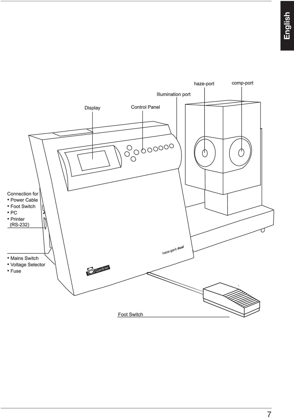
16 4 Features 4.1 Device English The display is used to output measurement values and display messages from the SET-UP dialog. The button field is used for selecting and inputting functions. The haze port illuminates the specimen to be measured. The specimens to be measured are placed at the haze port. The comp port is used for compensation measurement for the ISO method. The side connections are used to connect the device to the mains electricity supply, foot switch, PC, and printer. The power switch is used to switch on the device. It also functions as a voltage selector and fuse switch. If you need both hands to hold the specimen, it is possible to start measurement by pressing the foot switch. 15

17 4 Features English 4.2 Operation Cursor Keys delete last Measurement and Selection key Reference measurement (Continuous Mode) statistic result operate set up reference transmittance haze transm. + haze on/off on/off delete all SET-UP Menu Measurement selection The operate and selection buttons are pressed to start the measurement and to select the measurement method. operate starts a measurement. reference starts a reference measurement in continuous measurement mode. transmittance selects the transmission measurement method. haze selects the haze measurement method. transm.+ haze selects both methods simultaneously. To display the SET-UP Menu press the set up button The cursor buttons are used to move the index mark along the menu for the selection of menu items. operate confirms the selection made. set up cancels a process. 16

18 5 Selecting the Measurement Method 5.1 Selecting the Measurement Method Two standardized measurement methods are available using this device. T ASTM English Compensated (ISO and 14782) H Uncompensated (ASTM D1003) The active measurement method is displayed on the top right. The measurement method can be changed from the SET-UP Menu. delete last This menu is accessed using the buttons shown here: statistic result operate set up The menu is opened by pressing the set up button. on/off on/off delete all To select options within the SET-UP Menu, use the cursor buttons and the operate and set up buttons. The other labels on the cursor buttons are irrelevant here. 17

19 5 Selecting the Measurement Method English Open the SET-UP Menu using the cursor buttons. The first part of the SET-UP Menu is shown on the display. To select the measurement method, scroll down to the item Method using the cursor buttons and press the operate button. The displayed method will change and a message will appear concerning the comp-port : SET UP MENU Calibrate Print Statistic Print Online: on Cont. Mode: off Language: USA Method: ISO Escape: SET UP Changing to ASTM: cover the comp-port. Changing to ISO: uncover from the comp-port. Once a measurement mode has been selected, the corresponding calibration routine is started immediately. Continue: Attention! Keep comp-port open ISO OPERATE 18

20 6 Calibration 6.1 Calibration Thanks to the use of state-of-the-art technology and the reference beam principle, calibration does not have to be carried out very often. We recommend a calibration interval of two months. Calibration is also necessary: at the initial startup, in the event of a drastic change in ambient temperature (for example, if the device has been moved to a new location), if a message appears on the display requesting calibration (e.g. following the modification of stored calibration values), if the measurement method has been changed. 6.2 How to Calibrate the Device Calibration is carried out in the SET- UP Menu. This menu is opened by pressing the set up button. Using the cursor buttons, select the menu item Calibration and then press the operate button. The dark measurement is carried out. Cover the haze-port with the dark standard and press the operate button again. To interrupt the calibration procedure at any time, press the set up button. CALIBRATION Zero Calibration Ready: Escape: Please cover haze-port ASTM OPERATE SET UP English 19
, if the measurement method has been changed. 6.")
21 6 Calibration English A message is shown on the display while the measurement is being carried out. Measurement active The bright measurement follows the dark measurement. For this, remove the dark standard from the hazeport and press the operate button. CALIBRATION 100% Calibration Please remove cover from haze-port ISO Ready: OPERATE The device completes the bright measurement and then returns to standby mode. Calibration is now complete and the device is ready to carry out measurements. T H ISO 6.3 Calibrating with other Standards The device can also be calibrated and tested with a reference standard in the ASTM measurement method (see Accessories/Delivery Package). To enable this, the calibration data for this standard must be already entered in the SET- UP menu (Chapter 10.12). In this case, the relevant standard must be placed at the haze-port for calibration. 20
22 6 Calibration For dark measurement, cover the haze-port with the dark standard and press the operate button. English The dark measurement is followed by bright measurement. For this, remove the dark standard from the haze-port and press the operate button again. You will then be asked to place the standard that was entered in the SET-UP Menu. Calibration is complete when you press the operate button and the device is ready for measurement. CALIBRATION Place Transm.stand at haze-port Ready: Escape: OPERATE SET UP To avoid confusion, please ensure that the value shown during calibration coincides with the data for the standard used. The manufacturer s original standards must be used to guarantee accurate calibration. 21
23 6 Calibration English 6.4 Additional Standards for Monitoring Test Equipment To check that the measurement device is working correctly, measurements should be performed at regular intervals with special test standards. The appropriate test standards are listed in the Ordering Guide. The displayed readings should fall within the specified values for the standard. If they do not, check that the standard was clean and that the device was correctly calibrated. If cleaning the standard and recalibration do not correct the error, please contact Customer Service. For information about cleaning the device, see Chapter Monitoring Test Equipment Under normal laboratory conditions and careful handling, an interval of one month is recommended for the monitoring of test equipment. If measuring conditions necessitate more frequent monitoring of the equipment, two sets of haze standards should be used: 1. Working Standards Any material that is suitably homogenous and stable can be used for routine testing. The working standards are based on primary standards. 2. Primary Standards The primary standards are not intended for daily monitoring but exclusively as reference material for the checking of working standards. Primary standards should be used as little as possible due to the risk of damage. The manufacturer s original standards must be used to guarantee accurate calibration. 6.6 Storing and Handling Standards 6.6 Storing and Handling The precision Standards of measurements can be considerably impaired by the use The precision of measurements can of damaged or dirty standards. be considerably impaired by the use Please ensure that standards are of damaged or dirty standards. clean and unscratched. The standard surfaces are very sensitive. Please ensure that standards are clean and unscratched. The standard surfaces are very sensitive. Therefore, you must not touch the standard surface and protect it Therefore, you must not touch the against scratching (store in a secure standard surface and protect it iplace). For instructions on the against scratching (store in a secure cleaning of standards, see Chapter iplace). For instructions on the 6.7. The standards must not be cleaning of standards, see Chapter exposed to direct sunlight or be 6.7. The standards must not be stored in a dirty or dusty environment. Contact with chemicals and exposed to direct sunlight or be stored in a dirty or dusty environment. Contact with chemicals and aggressive vapors must also be avoided. aggressive vapors must also be avoided. 22
24 6 Calibration 6.7 Cleaning The standard surfaces are very sensitive. Hence, standards should be cleaned as seldom as possible. Dust and lint can cause incorrect measurements. Thus, standards must be cleaned with oil-free compressed air before use. Never rub the standard dry! The rubbing action may cause scratches from surface dust. Extreme care must be taken when cleaning standards. Use a fresh soft cloth and wash the standards in distilled water. Do not apply pressure or rubbing action. Ensure that there are no particles adhering to the cloth that might damage the standard surface. Do not use aggressive cleaners such as solvents, rubbing alcohol, trichloroethylene, benzene, strong alcohols, acids or lyes. Chemical cleaners and polishes are equally damaging. To remove stubborn dirt, add a little household dish detergent (acid-free) to the water. Rinse in distilled water. Dry with oil-free compressed air and blow off any remaining dust or lint. Do not rub the standard dry! The rubbing action may cause scratches from surface dust. 6.8 The Validity of Standard Values Even if handled carefully, the measurement values of the standards can change due to environmental factors. Thus, primary standards should be measured regularly by the Byk-Gardner Service. A monitoring interval of one year is recommended in this case. English 23
25 7 Measurement English 7.1 ISO Method If the transm. + haze parameter is selected, the device is ready to carry out measurements in accordance with the ISO method. The comp-port is open. Press the operate button. You will then be requested to place the specimen at the comp-port. Ready: Place sample at comp-port OPERATE The specimen must be held level with the port during measurement. Press the operate button. The device will start measuring. The following message appears during measurement: Measurement active. You will then be requested to place the specimen at the haze port. Place the specimen at the haze port and press the operate button. Ready: Please place sample at haze-port OPERATE The following message is displayed again: Measurement active. The result is displayed and the measurement process is complete. Transmission measurement is identical to the measurement procedure described above. T H ISO 24
26 7 Measurement 7.2 ASTM Method The transm. + haze parameter is selected, the comp port is covered, and the device is ready to carry out measurements in accordance with the ASTM method. Place your specimen at the haze port and press operate. transm. + haze English The following message appears: Measurement active. Measurement active The result is shown on the display and measurement is complete. Transmission measurement follows the same procedure as that described above. T H ASTM 7.3 Haze Measurement If the Haze parameter is selected, the procedure is identical to those for the ISO and ASTM methods. Place the probe on the haze port and press operate. The result is appears after the Measurement active message. 25
27 8 Measurement Series with Statistics English 8.1 Measurement Series with Statistics The statistics function can be selected alone or for any combination of parameters. They are activated using the left/right cursor buttons. In this case, the indication above and below the buttons is valid. statistic on/off result on/off Statistics can only be recorded for one parameter in Continuous Mode. The statistic on/off button is used to switch the statistics function on or off for the existing representation of measurement values. T H ASTM The following data is also shown on the display: n = Number of measurements m = Mean s = Standard deviation STATISTIC ASTM T n= 14 m= 91.6 s= 1.2 H m= 17.0 s=
28 8 Measurement Series with Statistics All statistics data can be switched on by pressing the result on/off button. act = Last measured value; in Continuous Mode, this is the value for the inserted specimen m = Mean value min = Minimum value max = Maximum value s = Standard deviation v = Variance coefficient When the statistics function is active, the measured values are saved and retained when you switch to a different parameter or switch off the instrument. The saved values can be transmitted to a printer or PC via the serial interface. A previously saved measurement series can be called up again and continued if it has not been deleted. It is not possible to change calibration values while a series is running, as this would falsify the statistical results. 8.2 Statistics with Continuous Mode In Continuous Mode, measurements are displayed continuously but they are not saved automatically. To add a measurement to the measurement series, it is necessary to press the operate button. RESULT ASTM T H n= 14 act= m= min= max= s= v= S= n 1 n-1 i=1 2 (x i -x) V= 100 x s/m% 8.3 Deleting One Measurement delete last The delete last button deletes the last saved measurement. The counter variable n is decreased by Deleting All Measurements The delete last button deletes all measurement in this series. The deletion function only delete all relates to the parameters currently set in the memory area. English 27
29 9 Continuous Mode English In the normal measuring mode, individual measurements are started by pressing the operate button or the foot switch. In Continuous Mode, the specimen is measured repeatedly and the result on the display updated accordingly. This allows you to run a large specimen through the device to establish whether its quality is homogenous. The Continuous Mode function can only be implemented for a single parameter. If you try to switch to Continuous Mode for the transm. + Haze parameters, the following warning appears on the display: Select one parameter and select Continuous Mode in the SETUP menu by pressing the operate button. 9.1 Continuous Mode ISO Transmittance Transmittance measurement requires a compensation measurement as a reference. A message on the display will ask for the definition of the compensation. Place your specimen at the compport and press the operate button. The Measurement active message will appear on the display and the device will then start the continuous measurement. Then place the specimen at the haze-port. The values are displayed continuously. Ready: T Continuous reading CONT. MODE only in single mode Compensation Measurement Place Sample at comp-port 90.8 OPERATE ISO 28
30 9 Continuous Mode To add a value to the statistics, press the operate button. The following message appears on the display: Measurement active. The device will return to continuous mode. If the statistic function is activated (Chapter 8.3), the counter will increase by one after measurement. If you change the material to be measured, a new compensation measurement is required. Indicate the change by pressing the reference button. You will be asked to place the spepensation measurement is triggered cimen in the comp-port. The comby pressing the operate button. The device will then return to continuous mode. Haze The haze measurement requires the value of the total transmittance as a reference for the measured specimen. This is indicated in a message on the display. Place the specimen whose total transmittance is to be defined at the haze-port. The device will return to Continuous Mode on completion. reference Ready: Ready: Compensation Measurement Place Sample at comp-port Transmittance Measurement Please place Sample at haze-port OPERATE OPERATE CONT. MODE ISO H n= m= 14.6 s= 1.16 English 29
31 9 Continuous Mode English To add a value to the statistics, press the operate button. The following message appears on the display: Measurement active. The device will then return to Continuous Mode on completion. If you change the material to be tested, the transmission must be redefined. Indicate the change by pressing the reference button. A message on the display will request you to place the specimen in the haze port. The device will then return to Continuous Mode. reference Transmittance Measurement Please place Sample at haze-port Standby To protect the lamp, Continuous Mode is interrupted after a certain period if the device fails to establish any change in the measurement value at the beam aperture. Measurement is continued if a significant change is detected at the beam inlet (e.g. placing of a specimen). Ready: CONT. MODE T 89.5 Standby-Mode OPERATE ISO 30
32 9 Continuous Mode 9.2 Continuous Mode ASTM Transmittance Conversion to Continuous Mode in the ASTM measurement method is the same as that for ISO, the only difference being that the comp port must be covered. A message is displayed indicating this. There is no defi nition of compensation with this method. Neither are precautionary measures are required if the material being tested is changed. The measurement values are saved by pressing the operate button. English Haze The transmission must be measured with the Haze parameter. This is also indicated on the display. The redefi nition of the transmission is triggered by pressing the referen ce button. You will be requested to place the specimen at the haze-port. reference The device will carry out the measurement with the new reference. The haze value is then shown on the display. The corresponding transmission value is indicated in the top right corner of the display. 31
33 9 Continuous Mode English To save a measurement value and return to standby mode, proceed as described above under ISO Continuous Mode. 9.3 Continuous Mode Statistics It is also possible to carry out a statistical evaluation of the measurement values in Continuous Mode. The measured values are written to the same memory as in normal operation. Select the desired function by pressing the statistic : statistic or result button. on/off result The selected function is indicated on the display. You can now run the desired area of your specimen through the device and observe the measurement values on the display. If you wish to save a value, press the operate button or foot switch. on/off ASTM T: 89.4 H n= 11 CONT. MODE 12.7 m= 10.6 s=
34 10 SET-UP 10.1 General Information The SET-UP menu allows you to set the various device parameters, select a language, and carry out calibration. The SET-UP menu and settings within the menu are executed using these buttons: statistic on/off delete last result on/off operate set up English To call up the SET-UP menu, press the set up button. delete all An operator instruction message appears. To select the individual menu items or pages, press the up / down cursor buttons. Press the button: The first menu page appears with the following selection items. If you move down the menu with the button: the second page of the SET-UP menu appears. Select the menu item you would like to change by marking the item in question. Press the operate button to implement the change or press set up to cancel. The diagram shows the menu in ASTM mode. Select the menu item you would like to change by marking the item. Press the operate button to change or press set up button to cancel. The diagram shows the menu in the ASTM setting. The item Change Cal. Value does not feature in the ISO mode. SET UP MENU Calibrate Print Statistic Print Online: on Cont. Mode: off Language: USA Method: ASTM Escape: SET UP 33
35 10 SET-UP English 10.2 Calibration Calibration is described in Chapter 6 from page Print Statistics Select the Print Statistics menu item and press the operate button. The data in the selected statistics memory is output on the connected printer. SET UP MENU Calibrate Print Statistic Print Online: on Cont. Mode: off Language: USA Method: ASTM Escape: SET UP Print Statistic T : n= 8 Date: Time: :55 am 10.4 Print Online Select the Print Statistics menu item and press the operate button to change the setting. If the Print Online function is activated, the measurement data is output directly to the connected printer after each measurement. No.: Escape: SET UP 34
36 10 SET-UP 10.5 Continuous Mode If the Continuous Mode function is selected, the device constantly repeats the measurement procedure. This function can be used to check larger specimens for homogeneity (see Chapter 9). English 10.6 Language To change the language, select the menu item Language and press the operate button. The selection menu for the available languages is displayed. The currently selected language is marked. Select the desired language using the cursor buttons and press the operate button to confirm your selection Method It is possible to select between the ASTM and ISO measurement methods. The currently active measurement method is indicated under the Method menu item. To change the measurement method, select Method and press the operate button. The displayed measurement method is changed and the device immediately switches to the calibration function for the selected measurement method. You must now carry out the calibration. (Chapter 6, p 19). SET UP MENU Calibrate Print Statistic Print Online: on Cont. Mode: off Language: USA Method: ASTM Escape: SET UP German English French Italian Spanish Japanese Confirm: Escape: OPERATE SET UP 35
37 10 SET-UP English 10.8 Beeper The device emits a beep signal on completion of a measurement. The beep signal can be switched on or off from the Beeper menu item Adjust Date To change the date, select Adjust Date and press the operate button. SET UP MENU Beeper: Adjust Date Adjust Time Display Contrast Change Cal Value on Escape: SET UP The date input menu is displayed. Use the: buttons, to move the arrow to the item to be changed. Use the: buttons to change the value in the corresponding place. Years prior to 1980 are not accepted. 36
38 10 SET-UP Adjust Time To change the device time, select the item Adjust Time and press the operate button. SET UP MENU Beeper: Adjust Date Adjust Time Display Contrast Change Cal Value on English Escape: SET UP The time input menu is displayed. Using the : buttons, move the arrow to the item to be changed. Using the: Time: 15:40 New Time: hh:mm 15:45 Confirm: Escape: OPERATE SET UP buttons, change the value in the relevant place Display Contrast To change the display contrast, select the item Display Contrast and press the operate button. SET UP MENU Beeper: Adjust Date Adjust Time Display Contrast Change Cal Value on The input mask for changing the contrast is displayed. Using the : buttons, set the contrast on a scale of The higher the value, the higher the contrast. Escape: Contrast: 1 10 Confirm: Escape: SET UP OPERATE SET UP 37
39 10 SET-UP English Change Calibration Value This menu item is only available under the ASTM measurement method. The value for the calibration standard is stored in the measurement device. During calibration this data is assigned to the relevant standard. Transmission is 100% with free optical path. In individual cases, it may be necessary to adjust the stored data to a new standard, e.g., if you are using internal house standards whose transmission is known to you. You can also calibrate and check the device with the transmission standard set which is available as an accessory (See Chapter 6.2 Calibrating with Other Standards). Select the menu item Change Cal. Values Press the operate button. SET UP MENU Beeper: Adjust Date Adjust Time Display Contrast Change Cal Value on Select Transmission Std. and press the operate button. Escape: Change Cal. Values Input Trans Std. Save Std Values SET UP Escape: SET UP 38
40 10 SET-UP The value to be changed is shown as a four-digit figure on the display. The last digit here is the digit after the decimal point. Select the decimal point to be changed using the buttons: and change the value using the up/down cursor buttons. Confirm the change by pressing the operate button. The device will return to the Change Cal Values menu. Temporary Storage If you leave the Change Cal Values by pressing the set-up button (i.e. cancel), the altered value is adopted temporarily. The device starts calibrating. After the dark and light measurement, you will be requested to place the standard with the value just entered at the haze port. Insert the standard and press the operate button. The calibration is finished and the new transmission value is now saved until the device is switched off. When the device is switched on again, the following message appears beside the company logo. Calibration data is being updated. T.Std. = 100 Confirm: Escape: 1000 Change Cal. Values Input Trans Std. Save Std Values Escape: Adjusting Calibration Values OPERATE SET UP SET UP Standards must be clean and undamaged! English Continue: OPERATE 39
41 10 SET-UP English Continuous Storage To permanently store the altered value of a calibration standard in the device, go to the Change Cal. Values. menu and select the option Save Std Values using the cursor buttons and then press the operate button. The Save Std Values display appears. The old and new value are presented here. To confirm the new value, press the operate button. The device starts calibrating. After the dark and light measurement, you will be requested to place the standard with the value just entered at the haze port. Insert the standard and press the operate button. The calibration is finished and the new transmission value is now permanently stored. Change Cal. Values Input Trans Std. Save Std Values Escape: Initialize Instr. Save Data: Escape: SET UP Old New OPERATE SET UP Standards must be clean and undamaged! 40
42 11 Parameters 11.1 Appearance of Transparent Materials When a transparent specimen is illuminated by focused light, a number of effects may result, depending on the nature of the material: Homogenous material with a smooth surface Some of the light will be reflected from the border surfaces and some will pass through the specimen unaltered. The specimen will appear glossy and crystal clear. The intensity of the transmitted light will be diminished by the inherent absobance of the materials, dyes, or pigments. Haze Diffuse scattering will decrease the imaging quality of an object. Particles or irregularities in the material may act as scatterers. The light in these areas is diffused uniformly in all directions and the light intensity per angle is small. This reduces contrast and results in a milky or cloudy appearance. This effect is called haze Criteria for the Evaluation of Transparency The appearance of a transparent product is a function of gloss, color, and transparency. The key parameters with respect to transparency are total transmittance and haze. The total transmittance is the ratio of the total transmitted light to incident light. It is reduced by reflectance and absorbance. According to ASTM 1003, haze is the percentage of light that deviates from the incident beam by more than 2.5 on average. English 41
43 English 11 Parameters Light trap Illumination Specimen comp-port 11.3 The Measurement Principle A beam strikes the specimen and then enters an integrating sphere. The light, which is uniformly distributed by the matte white coating on the sphere wall is measured by a detector. The total transmittance is measured with the sphere outlet closed and haze is measured with the outlet open. In the measurement method based on ISO and ISO 14782, the sphere effectiveness is taken into account in the measurement Standards ASTM D 1003: Standard Test Method for Haze and Luminous Transmittance of Transparent Plastics. ASTM D 1044: Standard Test Method for Resistance of Transparent Plastics to Surface Abrasion. ISO Plastics - Determination of the total luminous transmittance of transparent materials. ISO Plastics - Determination of haze for transparent materials. 42
44 11 Parameters Calibration Specimen Measurement English No compensation: different sphere efficiency ASTM D 1003 Measurement conditions during calibration and actual measurement are different. While part of the light that enters through the outlet escapes calibration, during measurement the outlet with the specimen is closed. Thus, the light in the sphere is increased by the proportion which is reflected on the specimen. Calibration Measurement Specimen With compensation: same sphere efficiency ISO Measurement conditions during calibration and actual measurement are the same. The specimen is placed at the compensation outlet during calibration and during measurement it is placed at the measurement outlet. This means that the sphere efficacy is completely dependent on the reflectance properties of the specimen. The difference between the two measurement methods can be up to 2% for clear glossy specimens. 43
45 11 Parameters English 11.5 Notes For values of less than 10 %, the measurement range is automatically converted to a display with two decimal places. During measurement, the mean is taken across the illuminated surface of the specimen. As it cannot be assumed that the optical properties are the same for the entire surface of the specimen, we recommend taking readings at several points on the specimen and calculating a mean value. There is little sense in taking readings from dirty, scratched, or otherwise damaged specimen areas, unless you wish to obtain the measurements as an indication of the extent of the damage, e.g. measuring abrasion resistance (Taber Abraser). Specimen surfaces must be as plane-parallel as possible; a wedge shape will deflect light. When taking comparative measurements, note the specimen thickness, since absorbance and scattering increase in direct proportion to thickness. Differences in reflection characteristics may affect transparency measurements. If specimens are glossy on one side and dull on the other, the same surface should always be directed toward the sphere aperture. Optical quality cuvettes with plane-parallel walls and an edge length of at least 50 mm can be used to take readings on liquids (Chapter 15). In practice, it may be important to know whether scattering is caused by internal scatterers or surface structure. In these cases, surface scattering can be eliminated by immersing the specimen during the readings in a liquid with the same refractive index as the specimen. Only bulk scattering will then come into play. 44
46 12 Care and Maintenance English 12.1 Changing the Lamp Attention! First switch off the device and disconnect it from the mains by unplugging it. Allow the lamp to cool down before changing it. Remove the cover above the display. To do this, remove the top of the two screws. Press lightly on the side facing the display until it moves and then remove it. Pull the lead plug out of the socket. The lamp unit is secured with a knurled screw. Unscrew the latter and then pull the lamp unit with the knurled screw out of the base. Do not touch the inside of the device and do not allow any objects to fall into the device aperture! Carefully insert the new lamp device into the base. Do not touch the lamp glass with your fingers. Secure the lamp device with the knurled screw and connect the lead plug with the base inside the device. Check that no objects remain trapped in the device and close the cover by pushing it from behind into the guide and securing it with the screw on the chassis. The device must be recalibrated when the lamp has been changed. 45
47 English 12 Care and Maintenance 12.2 Changing a Fuse Caution: First switch off the device and disconnect it from the mains electricity supply by unplugging it. Caution: For continued protection against risk of fire replace only with same type and rating of fuse. Pull the fuse holder from the mains plug socket (left side of device) using a suitable tool (No. 2 screw driver). Replace the defective fuse with a new one. Use only the recommended fuse type (Technical Specifications, Chapter 14). Replace the fuse device so that the arrow beside the voltage used points to the mark on the device case. Only use the specified fuse type. Never resort to short circuiting! The marking on the voltage used must coincide with the marking on the device chassis. 46
48 12 Care and Maintenance English 12.3 Maintenance Attention! First switch off the device and disconnect it from the mains electricity supply by unplugging it. The device chassis is resistant to a number of solvents but cannot be guaranteed to withstand all chemicals. Use only a soft damp cloth for cleaning. A little rubbing alcohol or mild detergent may be used to remove stubborn dirt Clean the front lens of the clarity port only with a soft lint-free cloth. Never clean the interior of the detector sphere (haze-port)! If the instrument malfunctions, do not attempt to repair it yourself. Our Customer Service will be glad to provide you with rapid assistance. 47
49 13 Interface Description English The device is equipped with a serial interface ( RS-232 ) which can be used to control the device, for further processing of measurement data on PC, or the output of data on a corresponding printer. The device has a 9-pole SUB-D socket for data transmission with the following pin arrangement: Measurement device PC 3 TxD 3 RxD 2 RxD 2 TxD 7 RTS 5 CTS 8 CTS 4 RTS 5 GND 7 GND The serial asynchronous transmission is defined in the measurement device and is implemented on the basis of the following specifications: 9600 baud, 8 data bits, no parity, 1 stopbit
50 14 Technical Specifications Measurement geometry: Sample Port: Measurement Area: 0 /diffuse 21.0 mm (0.85 in.) 16.5 mm (0.65 in.) Color sensitivity: In spectral adaptation to CIE luminosity function y under standard illuminant D65 Measurement range: Transmission: 0 100% Haze: 0 100% Display 0.01 in area resolution: from 0.00 to in the range from 10.0 to 99.9 Repeatability: ± 0,1 units* Reproducibility: ± 0,4 units* Measurement 1 6 seconds time: (depending on mode) Statistics 3 x 999 values memory: battery buffered lithium cell 3V (CR 2450N FH) Interface : Serial RS-232 with dialog capacity Connections: RS-232: Foot switch: Voltage: Power consumption: Fuse: 9-pole Sub-D 15-pole Sub-D 230V/50 Hz, 115V/60 Hz max. 200 VA Slow blow 1.0A;250V (230 V) Slow blow 1.6A;250V (115 V) Operating temperature: + 10 C to + 40 C (+ 50 to 104 F) Storage temperature: Dimensions: Weight: 0 C to +50 C (+ 32 to 122 F) 39 x 67 x 24 cm (15 x 26 x 10 in.) 18 kg (40 lbs) *standard deviation Technical Data Subject to Alteration English 49
51 15 Delivery Information English Delivery package Order No. haze-gard dual AT-4727 basic version Comprising: for connection to PC or printer (6 cm and 12 cm) Accessories Haze Test Standards: Delivery package Order No. 40 character printer 230 V 40 character printer 115 V Abraser (resistance measurement) Transmission standards: General terms and conditions apply for warranty 50
52 16 Error Messages Cause The current statistics memory in the measurement device does not contain any data. No statistic values stored English Cause The connected printer is not responding. This error only occurs when statistics data is being printed. The printer is not polled during online mode. Escape: Printer not ready SET UP Remedy Check that the printer cable is correctly connected! Is the printer switched on? Is there paper in the printer? Is the printer expecting a postscript file? Cause Invalid date A date earlier than 1980 was input during SET-UP. Remedy The date input was ignored and the old date retained. Enter the correct date. 51
53 16 Error Messages English Cause The reference button was pressed although the device is not in Continuous Mode. Remedy None, this is merely provided for information purposes. Cause The current statistics memory is full. Remedy Delete the last value or entire memory by pressing the delete last or delete all button. Cause The RAM and EEPROM contain different calibration data as these were not saved following the changing of calibration values. Remedy The calibration data are automatically transmitted from the EEPROM to the RAM and thus the calibration values updated again. Cause The measurement device is in online mode and is hence controlled from the PC- Only the operate and referencee buttons and the foot switch are released. Continue: Ref. Measurement only in Continuous-Mode Memory full Adjusting Calibration Values Online Mode Keyboard inactive OPERATE 52
54 16 Error Messages Error messages during calibration (ISO and ASTM): If errors occur during calibration, the device evaluates the measurement process as an error and requests the following corrections, depending on the procedure involved: Cause During calibration to a different transmission standard (ASTM only), the value was incorrectly entered or an attempt was made to calibrate using the incorrect standard. Remedy Enter the correct value or use the correct standard. Cause The haze-port was not covered during dark measurement. Remedy Cover the haze-port. English Cause The cover or specimen were not removed for light measurement Remedy Remove cover or specimen. 53
55 English 54
56 Deutsch Diese Betriebsanleitung ist Bestandteil des Gerätes. Sie enthält wichtige Hinweise zur Aufstellung, Inbetriebnahme und Handhabung. Achten Sie bei der Weitergabe des Gerätes darauf, dass die Betriebsanleitung dem Gerät beigefügt ist. Sie ist vor Beginn der Arbeit aufmerksam zu lesen. Sollten Sie zusätzliche Fragen haben oder Informationen wünschen, wenden Sie sich bitte an Ihre regionale Servicestelle. Technik und Ausstattung entsprechen dem neuesten Stand optischer und elektronischer Technik. Weiterentwicklungen und Verbesserungen werden laufend berücksichtigt; daher können sich Abbildungen, Maße oder technische Daten, die in dieser Betriebsanleitung verwendet wurden, in der Zwischenzeit durch Anpassung an neue Erkenntnisse und Verbesserungen verändert haben. 3 55
57 Deutsch 56
58 Inhaltsverzeichnis 1 Sicherheitshinweise Sicherheitshinweise Systembeschreibung Systembeschreibung Inbetriebnahme Wichtige Hinweise vor der Inbetriebnahme Aufstellung Einschalten Bedienelemente Gerät Tastatur Wahl der Meßmethode Wahl der Meßmethode Kalibrierung Kalibrieren Durchführung der Kalibration Kalibrieren mit anderen Standards Zusatzstandards zur Prüfmittelüberwachung Prüfmittelüberwachung Aufbewahrung und Handhabung von Standards Reinigung Gültigkeit der Standardwerte Messung ISO Methode ASTM Methode Haze-Messung Meßreihen mit Statistik Meßreihen mit Statistik Statistik bei Dauermessung Messung löschen Alle löschen Dauermessung Dauermessung ISO Transmittance Haze Standby Dauermessung ASTM Dauermessung Statistik Deutsch 57
Electrical tests on Bosch unit injectors
 Valid for Bosch unit injectors with order numbers 0 414 700 / 0 414 701 / 0 414 702 Parts Kit Magnet*: - F00H.N37.925 - F00H.N37.933 - F00H.N37.934 * For allocation to the 10-place Bosch order number,
Electrical testing of Bosch common rail piezo injectors
 Applies to generation CRI 3: Bosch 10-position order number 0 445 115 = CRI 3-16 (CRI 3.0) 1600 bar 0 445 116 = CRI 3-18 (CRI 3.2) 1800 bar 0 445 117 = CRI 3-20 (CRI 3.3) 2000 bar Tools required: Hybrid
Tube Analyzer LogViewer 2.3
 Tube Analyzer LogViewer 2.3 User Manual Stand: 25.9.2015 Seite 1 von 11 Name Company Date Designed by WKS 28.02.2013 1 st Checker 2 nd Checker Version history Version Author Changes Date 1.0 Created 19.06.2015
Word-CRM-Upload-Button. User manual
 Word-CRM-Upload-Button User manual Word-CRM-Upload for MS CRM 2011 Content 1. Preface... 3 2. Installation... 4 2.1. Requirements... 4 2.1.1. Clients... 4 2.2. Installation guidelines... 5 2.2.1. Client...
CABLE TESTER. Manual DN-14003
 CABLE TESTER Manual DN-14003 Note: Please read and learn safety instructions before use or maintain the equipment This cable tester can t test any electrified product. 9V reduplicated battery is used in
p^db=`oj===pìééçêíáåñçêã~íáçå=
 p^db=`oj===pìééçêíáåñçêã~íáçå= Error: "Could not connect to the SQL Server Instance" or "Failed to open a connection to the database." When you attempt to launch ACT! by Sage or ACT by Sage Premium for
Newest Generation of the BS2 Corrosion/Warning and Measurement System
 Newest Generation of the BS2 Corrosion/Warning and Measurement System BS2 System Description: BS2 CorroDec 2G is a cable and energyless system module range for detecting corrosion, humidity and prevailing
Electrical testing of Bosch common rail solenoid valve (MV) injectors
 injectors") Applies to MV injector, generation: -CRI 1.0 / 2.0 / 2.1 / 2.2 -CRIN 1 / 2 / 3, with K oder AK plug Bosch 10-position order number Bosch-Bestellnummer CRI: 0 445 110 xxx Bosch-Bestellnummer CRIN: 0 445
Applies to MV injector, generation: -CRI 1.0 / 2.0 / 2.1 / 2.2 -CRIN 1 / 2 / 3, with K oder AK plug Bosch 10-position order number Bosch-Bestellnummer CRI: 0 445 110 xxx Bosch-Bestellnummer CRIN: 0 445
VGM. VGM information. HAMBURG SÜD VGM WEB PORTAL USER GUIDE June 2016
 Overview The Hamburg Süd VGM Web portal is an application that enables you to submit VGM information directly to Hamburg Süd via our e-portal Web page. You can choose to enter VGM information directly,
Electrical testing of Bosch common rail Injectors
 Electrical testing of Bosch common rail Injectors Contents: 1. Adapter cable for Hybridtester FSA 050 (article number 0 684 010 050 / 1 687 023 571) 2. Electrical testing of Bosch common rail solenoid
VGM. VGM information. HAMBURG SÜD VGM WEB PORTAL - USER GUIDE June 2016
 Overview The Hamburg Süd VGM-Portal is an application which enables to submit VGM information directly to Hamburg Süd via our e-portal web page. You can choose to insert VGM information directly, or download
VIDEO CALL CAMERA G-VCAM-01
 VIDEO CALL CAMERA G-VCAM-01 EN AUS GUTEM GRUND ENGLISH 07-10 2 SAFETY AND INFORMATION Safety 7 This camera is designed to transmit video and audio signals. All other uses are expressly prohibited. 7 Protect
Power supply Interference suppressed acc. to DIN EN /- 4, EN 55011, EN CI. B, power factor corrected Power factor BöSha LED driver
 Operating Instructions LED Mast Double Luminaire Callisto SC DB, incl. Inclination Adjustment, Single-Chip Technology (Please, read carefully before starting operation) Version: 16.01.2017 Model 369-M
ONLINE LICENCE GENERATOR
 Index Introduction... 2 Change language of the User Interface... 3 Menubar... 4 Sold Software... 5 Explanations of the choices:... 5 Call of a licence:... 7 Last query step... 9 Call multiple licenses:...
Die Dokumentation kann auf einem angeschlossenen Sartorius Messwertdrucker erfolgen.
 Q-App: USP V2 Bestimmung des Arbeitsbereiches von Waagen gem. USP Kapitel 41. Determination of the operating range of balances acc. USP Chapter 41. Beschreibung Diese Q-App ist zur Bestimmung des Arbeitsbereiches
ATEX-Check list. Compiled by: Date: Signature: Acceptable practice at the determination of flash point: Closed cup according to ISO 2719
 Fire and explosion hazard ATEX 137 1999/92/EG und ATEX 95 2014/34/EU Danger assessment and determination of explosion protection zone for the test space as well as the installation site ATEX-Check list
OPERATING INSTRUCTIONS Test pump ZG 5.1. and ZG 5.2.
 Elektromotoren und Gerätebau Barleben GmbH OPERATING INSTRUCTIONS Test pump ZG 5.1. and ZG 5.2. Elektromotoren und Gerätebau Barleben GmbH 2 Inhaltsverzeichnis Page 1 Use 4 2 Design features 4 2.1 Test
Parameter-Updatesoftware PF-12 Plus
 Parameter-Updatesoftware PF-12 Plus Mai / May 2015 Inhalt 1. Durchführung des Parameter-Updates... 2 2. Kontakt... 6 Content 1. Performance of the parameter-update... 4 2. Contact... 6 1. Durchführung
Monitor VIS 3xx Kurzanleitung
 Monitor VIS 3xx Kurzanleitung 19.08.08 Art. Nr. 22261 Inhalt: 1. Spezifikationen...2 2. Tastenfunktionen...2 3. Menüführung und Einstellungen...3 Technik nach Maß Wöhler Monitor VIS 3xx 1. Spezifikationen
NEWSLETTER. FileDirector Version 2.5 Novelties. Filing system designer. Filing system in WinClient
 Filing system designer FileDirector Version 2.5 Novelties FileDirector offers an easy way to design the filing system in WinClient. The filing system provides an Explorer-like structure in WinClient. The
PROFIBUS-DP Repeater 1 to 1 and 1 to 5 with optional level converter module
 LSS PROFIBUS-DP Repeater 1 to 1 and 1 to 5 with optional level converter module The LSS PROFIBUS-DP repeaters 1 to 1 and 1 to 5 are used for coupling up to six PROFIBUS bus segments in RS 485 bus technology.
Cameraserver mini. commissioning. Ihre Vision ist unsere Aufgabe
 Cameraserver mini commissioning Page 1 Cameraserver - commissioning Contents 1. Plug IN... 3 2. Turn ON... 3 3. Network configuration... 4 4. Client-Installation... 6 4.1 Desktop Client... 6 4.2 Silverlight
Hazards and measures against hazards by implementation of safe pneumatic circuits
 Application of EN ISO 13849-1 in electro-pneumatic control systems Hazards and measures against hazards by implementation of safe pneumatic circuits These examples of switching circuits are offered free
Ingenics Project Portal
 Version: 00; Status: E Seite: 1/6 This document is drawn to show the functions of the project portal developed by Ingenics AG. To use the portal enter the following URL in your Browser: https://projectportal.ingenics.de
Snap-in switch for switches PSE, MSM and MCS 30
 Product manual Snap-in switch for switches PSE, MSM and MCS 30 CONTENTS 1. PRODUCT DESCRIPTION 2. DATA AND DIMENSIONAL DRAWINGS 2.1. Technical Data 2.2. Dimensions of PSE with a Mounting Diameter 19 mm
Evidence of Performance
 Air permeability, Watertightness, Resistance to wind load, Operating forces, Mechanical properties, Mechanical durability, Impact resistance Expert Statement No. 15-002226-PR01 (02) Product Designation
Beschreibung. Process Description: Sartorius Bestellnummer / Order No.:
 Q-App: USP Advanced Bestimmung des Arbeitsbereiches von Waagen gem. USP Kapitel 41 mit Auswertung über HTML (Q-Web) Determination of the operating range of balances acc. USP Chapter 41 with evaluation
Outdoor-Tasche. Operating Instructions Bedienungsanleitung GB D
 00 181243 Outdoor Case Outdoor-Tasche Splish Splash Operating Instructions Bedienungsanleitung GB D A B C D OPEN G Operating instruction 1. Important Notes Children are not permitted to play with the device.
p^db=`oj===pìééçêíáåñçêã~íáçå=
 p^db=`oj===pìééçêíáåñçêã~íáçå= How to Disable User Account Control (UAC) in Windows Vista You are attempting to install or uninstall ACT! when Windows does not allow you access to needed files or folders.
SETUP TOOL. Bedienungsanleitung User s Manual
 Bedienungsanleitung User s Manual Bitte lesen Sie diese Anleitung vor der Inbetriebnahme sorgfältig durch Please read the instructions carefully before use 1. Eigenschaften Das Setup Tool ist ein speziell
How-To-Do. Hardware Configuration of the CC03 via SIMATIC Manager from Siemens
 How-To-Do Hardware Configuration of the CC03 via SIMATIC Manager from Siemens Content Hardware Configuration of the CC03 via SIMATIC Manager from Siemens... 1 1 General... 2 1.1 Information... 2 1.2 Reference...
LOC Pharma. Anlage. Lieferantenfragebogen Supplier Questionnaire. 9. Is the warehouse temperature controlled or air-conditioned?
 Please complete this questionnaire and return to: z.h. Leiter Qualitätsmanagement info@loc-pharma.de Name and position of person completing the questionnaire Signature Date 1. Name of Company 2. Address
Digital Inclinometer. Elektronischer Neigungmesser. Bedienungsanleitung
 Digital Inclinometer Art.No. M541 Manual Page 2-4 Elektronischer Neigungmesser Art.Nr. M541 Bedienungsanleitung Seite 5-8 Please read the manual carefully before use ON/OFF button: push this button shortly,
Exercise (Part V) Anastasia Mochalova, Lehrstuhl für ABWL und Wirtschaftsinformatik, Kath. Universität Eichstätt-Ingolstadt 1
 Anastasia Mochalova, Lehrstuhl für ABWL und Wirtschaftsinformatik, Kath. Universität Eichstätt-Ingolstadt 1") Exercise (Part V) Notes: The exercise is based on Microsoft Dynamics CRM Online. For all screenshots: Copyright Microsoft Corporation. The sign ## is you personal number to be used in all exercises. All
Exercise (Part V) Notes: The exercise is based on Microsoft Dynamics CRM Online. For all screenshots: Copyright Microsoft Corporation. The sign ## is you personal number to be used in all exercises. All
Overview thermostat/ temperature controller
 Thermostat TR-238 The Thermostat TR-238 is a electronic two-level controller for controlling of and in climate control units and vehicles. Voltage range (12V): Voltage range (24V): Control range: Hystereses:
MQ964..GB MQ965..GB. en Operating instructions ar
 MQ964..GB MQ965..GB en Operating instructions ar MQ964-965GB-Uniklein_en-ar.book Seite 2 Donnerstag, 4. Dezember 2014 4:39 16 en English...........................................................3 ar...........................................................6.................................................
1. General information... 2 2. Login... 2 3. Home... 3 4. Current applications... 3
 User Manual for Marketing Authorisation and Lifecycle Management of Medicines Inhalt: User Manual for Marketing Authorisation and Lifecycle Management of Medicines... 1 1. General information... 2 2. Login...
Therefore the respective option of the password-protected menu ("UPDATE TUBE DATA BASE") has to be selected:
 has to be selected:") ENGLISH Version Update Dräger X-act 5000 ("UPDATE TUBE DATA BASE") The "BARCODE OPERATION AIR" mode is used to automatically transfer the needed measurement parameters to the instrument. The Dräger X-act
ENGLISH Version Update Dräger X-act 5000 ("UPDATE TUBE DATA BASE") The "BARCODE OPERATION AIR" mode is used to automatically transfer the needed measurement parameters to the instrument. The Dräger X-act
Digital Rockwell-Testing-Machine KB 150 R
 Digital Rockwell-Testing-Machine KB 150 R Rockwell, ball indentation, Vickers HVT, Brinell HBT Bright LCD color display Flexible software control motorized load system with load cell, closed loop system
EMCO Installationsanleitung Installation instructions
 EMCO Installationsanleitung Installation instructions Installationsanleitung Installation instructions Digitalanzeige digital display C40, FB450 L, FB600 L, EM 14D/17D/20D Ausgabe Edition A 2009-12 Deutsch...2
Application Note. Import Jinx! Scenes into the DMX-Configurator
 Application Note Import Jinx! Scenes into the DMX-Configurator Import Jinx! Scenen into the DMX-Configurator 2 The Freeware Jinx! is an user friendly, well understandable software and furthermore equipped
MultiPortSwitch. VGA Umschalter. Version 1.0 As of April 19 th 2004 Subject to change!
 MultiPortSwitch VGA Umschalter Version 1.0 As of April 19 th 2004 Subject to change! Document version: Version Date Name Comment 1.00 29.03.2004 J. Klein Compiled Distributed by: idata industrielle Datensysteme
Titelbild1 ANSYS. Customer Portal LogIn
 Titelbild1 ANSYS Customer Portal LogIn 1 Neuanmeldung Neuanmeldung: Bitte Not yet a member anklicken Adressen-Check Adressdaten eintragen Customer No. ist hier bereits erforderlich HERE - Button Hier nochmal
Restschmutzanalyse Residual Dirt Analysis
 Q-App: Restschmutzanalyse Residual Dirt Analysis Differenzwägeapplikation, mit individueller Proben ID Differential weighing application with individual Sample ID Beschreibung Gravimetrische Bestimmung
RS232-Verbindung, RXU10 Herstellen einer RS232-Verbindung zwischen PC und Messgerät oder Modem und Messgerät
 Betriebsanleitung RS232-Verbindung, RXU10 Herstellen einer RS232-Verbindung zwischen PC und Messgerät oder Modem und Messgerät ä 2 Operating Instructions RS232 Connection, RXU10 Setting up an RS232 connection
miditech 4merge 4-fach MIDI Merger mit :
 miditech 4merge 4-fach MIDI Merger mit : 4 x MIDI Input Port, 4 LEDs für MIDI In Signale 1 x MIDI Output Port MIDI USB Port, auch für USB Power Adapter Power LED und LOGO LEDs Hochwertiges Aluminium Gehäuse
Walter Buchmayr Ges.m.b.H.
 Seite 1/10 Chapter Description Page 1 Advantages 3 2 Performance description 4 3 Settings 5 4 Options 6 5 Technical data 7 6 Pictures 8 http://members.aon.at/buchmayrgmbh e-mail: walter.buchmayr.gmbh@aon.at
Quick Guide Home Network Mode
 Quick Guide Home Network Mode English > 1 German > 3 About the Home Network Mode EN Tivizen Nano & iplug normally work on their own created networks (whose SSID starts with tivizentv or iplug ) in which
Mock Exam Behavioral Finance
 Mock Exam Behavioral Finance For the following 4 questions you have 60 minutes. You may receive up to 60 points, i.e. on average you should spend about 1 minute per point. Please note: You may use a pocket
Kurzanleitung um Transponder mit einem scemtec TT Reader und der Software UniDemo zu lesen
 Kurzanleitung um Transponder mit einem scemtec TT Reader und der Software UniDemo zu lesen QuickStart Guide to read a transponder with a scemtec TT reader and software UniDemo Voraussetzung: - PC mit der
https://portal.microsoftonline.com
 Sie haben nun Office über Office365 bezogen. Ihr Account wird in Kürze in dem Office365 Portal angelegt. Anschließend können Sie, wie unten beschrieben, die Software beziehen. Congratulations, you have
rot red braun brown rot red RS-8 rot red braun brown R S V~
 Kleiner Ring 9 /Germany Phone: 0049 4122 / 977 381 Fax: 0049 4122 / 977 382 Sample connections: Feedback module with integrated detection of occupied tracks for the RS-feedback bus (Lenz Digital plus)
Can I use an older device with a new GSD file? It is always the best to use the latest GSD file since this is downward compatible to older versions.
 EUCHNER GmbH + Co. KG Postfach 10 01 52 D-70745 Leinfelden-Echterdingen MGB PROFINET You will require the corresponding GSD file in GSDML format in order to integrate the MGB system: GSDML-Vx.x-EUCHNER-MGB_xxxxxx-YYYYMMDD.xml
Lukas Hydraulik GmbH Weinstraße 39 D Erlangen. Mr. Sauerbier. Lukas Hydraulik GmbH Weinstraße 39 D Erlangen
 Technical Report No. 028-71 30 95685-350 of 22.02.2017 Client: Lukas Hydraulik GmbH Weinstraße 39 D-91058 Erlangen Mr. Sauerbier Manufacturing location: Lukas Hydraulik GmbH Weinstraße 39 D-91058 Erlangen
UWC 8801 / 8802 / 8803
 Wandbedieneinheit Wall Panel UWC 8801 / 8802 / 8803 Bedienungsanleitung User Manual BDA V130601DE UWC 8801 Wandbedieneinheit Anschluss Vor dem Anschluss ist der UMM 8800 unbedingt auszuschalten. Die Übertragung
JTAGMaps Quick Installation Guide
 Index Index... 1 ENGLISH... 2 Introduction... 2 Requirements... 2 1. Installation... 3 2. Open JTAG Maps... 4 3. Request a free JTAG Maps license... 4 4. Pointing to the license file... 5 5. JTAG Maps
Datasheet. Page 1 of 7
 Features 20 Encoder Positions 4-way Joystick LED-Illumination high quality signal processing Benefits Tactile multi purpose application premium design Hall Effect technology Applications Multiple switch
Produktinformation _147PNdeen
 Produktinformation 201105_147PNdeen Neue Software für die TOUCH PC Auswuchtmaschinen BM 35 Touch, BM 45 Touch, BM 55 Touch Mit der Einführung der BM 11 Touch in die Nussbaum Produktlinie der Rad Auswuchtmaschinen
KURZANLEITUNG. Firmware-Upgrade: Wie geht das eigentlich?
 KURZANLEITUNG Firmware-Upgrade: Wie geht das eigentlich? Die Firmware ist eine Software, die auf der IP-Kamera installiert ist und alle Funktionen des Gerätes steuert. Nach dem Firmware-Update stehen Ihnen
Release Notes BRICKware 7.5.4. Copyright 23. March 2010 Funkwerk Enterprise Communications GmbH Version 1.0
 Release Notes BRICKware 7.5.4 Copyright 23. March 2010 Funkwerk Enterprise Communications GmbH Version 1.0 Purpose This document describes new features, changes, and solved problems of BRICKware 7.5.4.
B/S/H/ Startfolie. B/S/H Bosch und Siemens Hausgeräte GmbH - KDT-T B/S/H Bosch und Siemens Hausgeräte GmbH KDT-T
 Startfolie B/S/H/ 1 Product division Event Location Refrigeration Side by Side USA B/S/H Bosch und Siemens Hausgeräte GmbH KDT-T 2 Side-by-Side Appliances Models: Bosch Siemens KAN 56V** KAN58A** KA58NA**with
Where are we now? The administration building M 3. Voransicht
 Let me show you around 9 von 26 Where are we now? The administration building M 3 12 von 26 Let me show you around Presenting your company 2 I M 5 Prepositions of place and movement There are many prepositions
Registration of residence at Citizens Office (Bürgerbüro)
") Registration of residence at Citizens Office (Bürgerbüro) Opening times in the Citizens Office (Bürgerbüro): Monday to Friday 08.30 am 12.30 pm Thursday 14.00 pm 17.00 pm or by appointment via the Citizens
Registration of residence at Citizens Office (Bürgerbüro) Opening times in the Citizens Office (Bürgerbüro): Monday to Friday 08.30 am 12.30 pm Thursday 14.00 pm 17.00 pm or by appointment via the Citizens
Firma, Adresse: Company, Adress. Namen der verantwortlichen für die Qualitätssicherung: Names of resposible person for quality assurance:
 Firma, Adresse: Company, Adress Namen der verantwortlichen für die Qualitätssicherung: Names of resposible person for quality assurance: 1. Qualitätsnachweis Quality control Werden Prüfunterlagen systematisch
DENTAL IMPLANTS BY CAMLOG medical
 IMPLANT PASS DENTAL IMPLANTS BY CAMLOG medical devices made in germany for your well-being and a natural appearance. Personal data Surname First name Address ZIP code City Date of birth Health insurance
Weather forecast in Accra
 Weather forecast in Accra Thursday Friday Saturday Sunday 30 C 31 C 29 C 28 C f = 9 5 c + 32 Temperature in Fahrenheit Temperature in Celsius 2 Converting Celsius to Fahrenheit f = 9 5 c + 32 tempc = 21
Softwareupdate-Anleitung // AC Porty L Netzteileinschub
 1 Softwareupdate-Anleitung // AC Porty L Netzteileinschub Softwareupdate-Anleitung // AC Porty L Netzteileinschub HENSEL-VISIT GmbH & Co. KG Robert-Bunsen-Str. 3 D-97076 Würzburg-Lengfeld GERMANY Tel./Phone:
Mitglied der Leibniz-Gemeinschaft
 Methods of research into dictionary use: online questionnaires Annette Klosa (Institut für Deutsche Sprache, Mannheim) 5. Arbeitstreffen Netzwerk Internetlexikografie, Leiden, 25./26. März 2013 Content
Network Setup. PC Application
 PC Application 1. USB stick driver installed and stick inserted or Lunatone DALI Cockpit installed and DALI USB stick inserted PC application installed 2. Network set-up for a Zigbee USB stick or DALI
Frequently asked Questions for Kaercher Citrix (apps.kaercher.com)
") Frequently asked Questions for Kaercher Citrix (apps.kaercher.com) Inhalt Content Citrix-Anmeldung Login to Citrix Was bedeutet PIN und Token (bei Anmeldungen aus dem Internet)? What does PIN and Token
Frequently asked Questions for Kaercher Citrix (apps.kaercher.com) Inhalt Content Citrix-Anmeldung Login to Citrix Was bedeutet PIN und Token (bei Anmeldungen aus dem Internet)? What does PIN and Token
Test report. Bericht Nr.: PH001/10. Gruppe Physik Seite 1 von 6. Liquisol Mr. Tom Huymans Lindberg Oelegem BELGIUM. Client: Order No.
 Bericht Nr.: PH1/1 Fraunhofer Institut für Produktionstechnik und Automatisierung (IPA) Tel.: +49 711 6878-, Fax: +49 711 6878-79 Gruppe Physik Seite 1 von 6 Test report Client: Liquisol Mr. Tom Huymans
EMCO Installationsanleitung / Installation instructions
 EMCO Installationsanleitung / Installation instructions Installationsanleitung Installation instructions Digitalanzeige digital display C40, FB450 L, FB600 L, EM 14D/17D/20D Ausgabe / Edition B 2012-03
Shock pulse measurement principle
 Shock pulse measurement principle a [m/s²] 4.0 3.5 3.0 Roller bearing signals in 36 khz range Natural sensor frequency = 36 khz 2.5 2.0 1.5 1.0 0.5 0.0-0.5-1.0-1.5-2.0-2.5-3.0-3.5-4.0 350 360 370 380 390
How to access licensed products from providers who are already operating productively in. General Information... 2. Shibboleth login...
 Shibboleth Tutorial How to access licensed products from providers who are already operating productively in the SWITCHaai federation. General Information... 2 Shibboleth login... 2 Separate registration
MECHANICAL WRENCH SERIES
 MECANICAL WRENC SERIES MECANICAL WRENC SERIES The mechanical wrenches in the new Atlas Copco Saltus product line form the basis for manual tightening. They enable you to find the optimal solution for
Lukas Hydraulik GmbH Weinstraße 39 D Erlangen. Mr. Sauerbier. Lukas Hydraulik GmbH Weinstraße 39 D Erlangen. edraulic rescue equipment
 Technical Report No. 028-7130 95685-050 of 22.02.2017 Client: Lukas Hydraulik GmbH Weinstraße 39 D-91058 Erlangen Mr. Sauerbier Manufacturing location: Lukas Hydraulik GmbH Weinstraße 39 D-91058 Erlangen
Supplier Questionnaire
 Supplier Questionnaire Dear madam, dear sir, We would like to add your company to our list of suppliers. Our company serves the defence industry and fills orders for replacement parts, including orders
Finite Difference Method (FDM)
") Finite Difference Method (FDM) home/lehre/vl-mhs-1-e/folien/vorlesung/2a_fdm/cover_sheet.tex page 1 of 15. p.1/15 Table of contents 1. Problem 2. Governing Equation 3. Finite Difference-Approximation 4.
Finite Difference Method (FDM) home/lehre/vl-mhs-1-e/folien/vorlesung/2a_fdm/cover_sheet.tex page 1 of 15. p.1/15 Table of contents 1. Problem 2. Governing Equation 3. Finite Difference-Approximation 4.
Die Bedeutung neurowissenschaftlicher Erkenntnisse für die Werbung (German Edition)
") Die Bedeutung neurowissenschaftlicher Erkenntnisse für die Werbung (German Edition) Lisa Johann Click here if your download doesn"t start automatically Download and Read Free Online Die Bedeutung neurowissenschaftlicher
Die Bedeutung neurowissenschaftlicher Erkenntnisse für die Werbung (German Edition) Lisa Johann Click here if your download doesn"t start automatically Download and Read Free Online Die Bedeutung neurowissenschaftlicher
Benutzerhandbuch / User s Manual RUPS 2000 / -B1
 RUPS 2000 / RUPS 2000-B1 Benutzerhandbuch / User s Manual RUPS 2000 / -B1 Deutsch English Benutzerhandbuch RUPS 2000 / RUPS 2000-B1 Deutsch In diesem Benutzerhandbuch finden Sie eine Kurzanleitung zu Installation
CB RADIO Service Manual AE 6890
 CB RADIO Service Manual AE 6890 Downloaded from www.cbradio.nl Technische Mitteilung zu AE 6890 Problem: Bei Montage einer schlecht geerdeten Antenne oder einer Antenne mit schlechtem SWR sehr nahe am
Exercise (Part I) Anastasia Mochalova, Lehrstuhl für ABWL und Wirtschaftsinformatik, Kath. Universität Eichstätt-Ingolstadt 1
 Anastasia Mochalova, Lehrstuhl für ABWL und Wirtschaftsinformatik, Kath. Universität Eichstätt-Ingolstadt 1") Exercise (Part I) Notes: The exercise is based on Microsoft Dynamics CRM Online. For all screenshots: Copyright Microsoft Corporation. The sign ## is you personal number to be used in all exercises. All
Exercise (Part I) Notes: The exercise is based on Microsoft Dynamics CRM Online. For all screenshots: Copyright Microsoft Corporation. The sign ## is you personal number to be used in all exercises. All
Magic Figures. We note that in the example magic square the numbers 1 9 are used. All three rows (columns) have equal sum, called the magic number.
 have equal sum, called the magic number.") Magic Figures Introduction: This lesson builds on ideas from Magic Squares. Students are introduced to a wider collection of Magic Figures and consider constraints on the Magic Number associated with such
Magic Figures Introduction: This lesson builds on ideas from Magic Squares. Students are introduced to a wider collection of Magic Figures and consider constraints on the Magic Number associated with such
Anleitung zur Schnellinstallation TFM-560X YO.13
 Anleitung zur Schnellinstallation TFM-560X YO.13 Table of Contents Deutsch 1 1. Bevor Sie anfangen 1 2. Installation 2 Troubleshooting 6 Version 06.08.2011 1. Bevor Sie anfangen Packungsinhalt ŸTFM-560X
Attention: Give your answers to problem 1 and problem 2 directly below the questions in the exam question sheet. ,and C = [ ].
![Attention: Give your answers to problem 1 and problem 2 directly below the questions in the exam question sheet. ,and C = [ ].](/thumbs/72/66904987.jpg "Attention: Give your answers to problem 1 and problem 2 directly below the questions in the exam question sheet. ,and C = [ ].") Page 1 LAST NAME FIRST NAME MATRIKEL-NO. Attention: Give your answers to problem 1 and problem 2 directly below the questions in the exam question sheet. Problem 1 (15 points) a) (1 point) A system description
Page 1 LAST NAME FIRST NAME MATRIKEL-NO. Attention: Give your answers to problem 1 and problem 2 directly below the questions in the exam question sheet. Problem 1 (15 points) a) (1 point) A system description
Produktinformation Access-Gateway. Product information Access gateway AGW 670-0
 Produktinformation Access-Gateway Product information Access gateway AGW 670-0 1 2 3 4 2 Deutsch Anwendung Access-Gateway zur physikalischen Trennung von 2 Netzwerken an einem Access-Server. Durch den
Exercise (Part XI) Anastasia Mochalova, Lehrstuhl für ABWL und Wirtschaftsinformatik, Kath. Universität Eichstätt-Ingolstadt 1
 Anastasia Mochalova, Lehrstuhl für ABWL und Wirtschaftsinformatik, Kath. Universität Eichstätt-Ingolstadt 1") Exercise (Part XI) Notes: The exercise is based on Microsoft Dynamics CRM Online. For all screenshots: Copyright Microsoft Corporation. The sign ## is you personal number to be used in all exercises. All
Exercise (Part XI) Notes: The exercise is based on Microsoft Dynamics CRM Online. For all screenshots: Copyright Microsoft Corporation. The sign ## is you personal number to be used in all exercises. All
UNIGATE CL Konfiguration mit WINGATE
 UNIGATE CL Konfiguration mit WINGATE - UNIGATE CL Configuration via WINGATE Art.-Nr.: V3928 Deutschmann Automation GmbH & Co. KG Carl-Zeiss-Str. 8 D-65520 Bad Camberg Phone: +49-(0)6434-9433-0 Hotline:
Uhrenbeweger Watch winders. Crystal
 Uhrenbeweger Watch winders Crystal Sehr geehrter Kunde, unsere Uhrenbeweger sind so konstruiert, dass sie trotz kompakter Abmessungen nur geringe Laufgeräusche verursachen. Jeder Antrieb erzeugt jedoch
hanit Assembly Instruction - Sandbox System Thar -
 Thank you for purchasing a hanit recycling plastic product, We wish you a lot of pleasure with that product. Please find below important installation instructions which need to be taken into consideration
v i r t u A L C O M P o r t s
 v i r t u A L C O M P o r t s (HO720 / HO730) Installieren und Einstellen Installation and Settings Deutsch / English Installieren und Einstellen des virtuellen COM Ports (HO720 / HO730) Einleitung Laden
How-To-Do. Hardware Configuration of the CPU 317NET with external CPs on the SPEED Bus by SIMATIC Manager from Siemens
 How-To-Do Hardware Configuration of the CPU 317NET with external CPs on the SPEED Bus by SIMATIC Manager from Siemens Content Hardware Configuration of the CPU 317NET with external CPs on the SPEED Bus
USB -> Seriell Adapterkabel Benutzerhandbuch
 USB -> Seriell Adapterkabel Benutzerhandbuch 1. Produkt Eigenschaften 1 2. System Vorraussetzungen 1 3. Treiber Installation (Alle Windows Systeme) 1 4. Den COM Port ändern 2 5. Einstellen eines RS232
Datenblatt. Remote-I/O - u-remote UR20-4AO-UI or 4-wire connection; 16-bit resolution; 4 outputs
 2- or 4-wire connection; 16-bit resolution; 4 outputs The analogue output module controls up to 4 analogue actuators with +/-10 V, +/-5 V, 0...10 V, 0...5 V, 2...10 V, 1...5 V, 0...20 ma or 4...20 ma with
TomTom WEBFLEET Tachograph
 TomTom WEBFLEET Tachograph Installation TG, 17.06.2013 Terms & Conditions Customers can sign-up for WEBFLEET Tachograph Management using the additional services form. Remote download Price: NAT: 9,90.-/EU:
Anleitung zur Verwendung des Update-Tools für
 English version see below (page 10) Anleitung zur Verwendung des Update-Tools für - KW DDC Steuergeräte - KW DDC WLAN Module - KW DLC Steuergeräte - KW DLC WLAN Module Bitte beachten Sie: jedes Steuergerät
Zusatz zur Betriebsanleitung Addendum to the Operating Instructions
 Drive Technology \ Drive Automation \ System Integration \ Services Zusatz zur Betriebsanleitung Addendum to the Operating Instructions Austausch von MOVIGEAR -S01 durch MOVIGEAR -DSC-B Replacing MOVIGEAR
vcdm im Wandel Vorstellung des neuen User Interfaces und Austausch zur Funktionalität V
 vcdm im Wandel Vorstellung des neuen User Interfaces und Austausch zur Funktionalität V0.1 2018-10-02 Agenda vcdm User Interface History Current state of User Interface User Interface X-mas 2018 Missing
Notice: All mentioned inventors have to sign the Report of Invention (see page 3)!!!
!!!") REPORT OF INVENTION Please send a copy to An die Abteilung Technologietransfer der Universität/Hochschule An die Technologie-Lizenz-Büro (TLB) der Baden-Württembergischen Hochschulen GmbH Ettlinger Straße
REPORT OF INVENTION Please send a copy to An die Abteilung Technologietransfer der Universität/Hochschule An die Technologie-Lizenz-Büro (TLB) der Baden-Württembergischen Hochschulen GmbH Ettlinger Straße