BigSteam Steam Engine
|
|
|
- Bernhard Salzmann
- vor 7 Jahren
- Abrufe
Transkript
1 BigSteam Steam Engine Instruction Manual Montage- und Bedienungsanleitung

2 Page / Seite 2 Before running the engine please read this instruction manual carefully. Attention: The Steam Engine BigSteam is not a toy and not suitable for children. Vor Inbetriebnahme bitte diese Anleitung sorgfältig lesen. Achtung: Die Dampfmaschine BigSteam ist kein Spielzeug und nicht für Kinder geeignet! Safety Instructions Running this engine requires the same safety precautions as handling open fire and flames. Never leave the operating engine without supervision. Before starting the engine make sure that there are no cracks in the glass boiler (23) and steam can easily pass the boiler nipple (26). Never heat the boiler without water inside. Do not touch the engine's hot boiler and the piston cylinder assembly. Exergia does not assume any responsibility for damages and injuries occurred due to the operation of this engine. Sicherheitshinweise Der Betrieb der Dampfmaschine erfordert die gleichen Sicherheitsvorkehrungen wie der Umgang mit Feuer und offenen Flammen. Die Dampfmaschine während des Betriebes niemals unbeaufsichtigt lassen. Die Dampfmaschine darf nur bei intaktem Kessel (23), der keine Risse aufweist, und durchgängigem Kesselnippel (26) in Betrieb genommen werden. Den Kessel niemals ohne Wasserfüllung beheizen. Den heissen Glaskessel und und die Kolben-Zylinder- Einheit während des Betriebs niemals berühren. Exergia übernimmt keinerlei Haftung für mögliche Schäden und Verletzungen, die sich aus dem Betrieb des Motors ergeben. 1. Introduction Thomas Newcomen's invention of the steam engine in 1705 and its improvement by James Watt sixty years later mark the beginning of the Industrial Revolution. Today the optimized Clausius Rankine cycle is the most common thermodynamic process in conventional power plants and thereby ensures the immense need of electrical energy for our modern life. BigSteam is a reminescence of the origin of this technology. Via its transparent boiler and cylinder it offers a direct sight of the thermodynamic processes, that enable the conversion of heat into useful mechanical energy. 1. Einführung Die Erfindung der Dampfmaschine im Jahre 1705 durch Thomas Newcomen und ihre Verbesserung durch James Watt ca. sechzig Jahre später bildete die Grundlage für den Beginn der Industriellen Revolution. Heute ist der optimierte Clausius Rankine Dampfprozess der am weitest verbreitete thermodynamische Prozess und bildet die Grundlage aller konventionellen Kraftwerke. BigSteam ist eine Remineszenz an die Ursprünge dieser Technologie und bietet durch die transparente Kesselund Zylinder-Ausführung quasi einen direkten Blick auf die thermodynamischen Prozesse, welche die Umwandlung von Wärme in Bewegungsenergie ermöglichen.
 and steam can easily pass the boiler nipple (26). Never heat the boiler without water inside.")
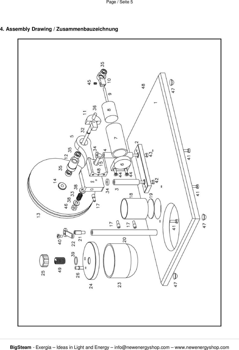
3 Page / Seite 3 2. Parts List / Teileliste 1 Acrylic baseplate Grundplatte 2 Base Fuß 3 Pillar, short Säule, kurz 4 Pillar, long Säule, lang 5 Arm Träger 6 Cylinder cover Zylinderdeckel 7 Power cylinder Arbeitszylinder 8/9 Power piston with rod Arbeitskolben mit Stange 10 Connecting rod Pleuel 11 Crank disk Kurbelscheibe 12 Bearing bush Lagerbuchse 13/14 Flywheel with bush Schwungrad mit Buchse 15/16 Axle with end piece Achse mit Endstück 17 Nipple (5) Nippel (5x) 18 Reservoir Becher 19 Reservoir base Becherboden 20 Exhaust steam pipe Abdampfrohr 21 Square end accommodation Vierkant-Aufnahme 22 Boiler attachment Kessel-Halter 23 Boiler Kessel 24 Boiler cover Kessel-Deckel 25 Boiler plug Kessel-Verschluss 26 Boiler Nipple Kessel-Nippel 27 Alcohol burner Spiritus-Brenner 28 Flexible pipe 120 mm, live steam Schlauch 120 mm, Frischdampf 29 Flexible pipe 65 mm, exhaust steam Schlauch 65 mm, Abdampf 30 Flexible pipe 60 mm, condensate Schlauch 60 mm, Kondensat 31 Flexible pipe 70 mm, drain Schlauch 70 mm, Abfluss 32 Distance piece Distanzring 33 Spring Feder 34 Plastic Shim (2x) Kunststoff-Scheibe (2x) 35 Ball bearing (3x) Kugellager (3x) 36 Crank pin Kurbelzapfen 37 Crankshaft Kurbelwelle 38 Shim (2x) Scheibe (2x) 39 O-Ring O-Ring 40 Cheese head screw M3x5 Zylinderschraube M3x5 41 Cheese head screw M3x10 (3x) Zylinderschraube M3x10 (3x) 42 Cheese head screw M3x40 Zylinderschraube M3x40 43 Cheese head screw M3x48 Zylinderschraube M3x48 44 Flat head screw M3x10 (2x) Senkschraube M3x10 (2x) 45 Headless screw M3x4 (2x) Gewindestift M3x4 (2x) 46 Nut M4 Mutter M4 47 Rubber piece (4x) Gummifuß (4x) 48 Cylinder cheek Zylinderwange 49 Stud M10 Gewindestück M10
 Nippel (5x) 18 Reservoir Becher 19 Reservoir base Becherboden 20 Exhaust steam pipe Abdampfrohr 21 Square end accommodation Vierkant-Aufnahme 22 Boiler")
4 Page / Seite 4 3. Complete View / Gesamtansicht

5 Page / Seite 5 4. Assembly Drawing / Zusammenbauzeichnung
6 Page / Seite 6 5. Assembly Instruction 5.1 Finishing Deburr all parts with rags. If you like you can polish the brass parts. 5.2 Gluing For all gluing use an epoxy (two components). Only put glue on the connecting faces of the parts. cylinder cover (6) cylinder cheek (48) hint: Fix the cylinder cover with the two flat head screws (44). When doing this be sure that the cylinder cheek has left a small gap to the arm (5) when it is assembled later. After that put the axle with end piece (15,16) into the cheek. power cylinder (7) cylinder cover (6) cylinder cheek (48) hint: Don't allow any glue on the axle with end piece (15,16). It is important to guarantee a free movement of this part. crank pin (36) crank disk (11) crankshaft (37) hint: Be aware of the correct alignment both of the pin's and the shaft's end to the disk. 3x nipple (17) arm (5) 2x nipple (17) exhaust steam pipe (20) square end accommodation (21) exhaust steam pipe (20) hint: Align one corner of the square end with the previously fixed nipples (17). 2x ball bearings (35) bearing bush (12) hint: Only use 2 tiny drops of glue for fixation. Don't allow any glue inside the ball bearings. ball bearing (35) connecting rod (10) bearing bush (12) - arm (5) boiler (23) boiler cover (24) 5. Zusammenbauanleitung 5.1 Endbearbeitung Entgraten Sie alle Grat haltigen Bauteile. Je nach persönlichem Anspruch schleifen Sie etwaige Werkstück- Flächen. 5.2 Kleben Verwenden Sie für die Klebeverbindungen einen Zwei- Komponenten-Kleber wie z.b. Uhu plus endfest 300 Zylinderdeckel (6) Zylinderwange (48) Hinweis: Fixieren Sie den Zylinderdeckel unter Verwendung der beiden Senkschrauben (44) etwas versetzt, so dass dieser die Zylinderwange nicht beim Gleiten auf dem Träger (5) behindert. Danach die Achse mit dem Endstück (15/16) in die Zylinderwange einschieben. Arbeitszylinder (7) Zylinderdeckel (6) Zylinderwange (48) Hinweis: Dabei keinen Kleber an die eingeschobene Achse mit Endstück (15/16) gelangen lassen. Diese muss sich frei bewegen können. Kurbelzapfen (36) Kurbelscheibe (11)- Kurbelwelle (37) Hinweis: Auf bündige Ausrichtung der Wellenenden achten. 3x Nippel (17) Träger (5) 2x Nippel (17) Abdampfrohr (20) Vierkantaufnahme (21) Abdampfrohr (20) Hinweis: So ausrichten, dass gegenüberliegende Ecken der Vierkantaufnahme in Achsrichtung der zuvor eingeklebten Nippel (17) liegen. 2x Kugellager (35) Lagerbuchse (12) Hinweis: Umfangfläche des Kugellagers mit 2 oder 3 kleinen Klebepunkten versehen. Achten Sie unbedingt darauf, dass kein Kleber in das Kugellager eindringt. Kugellager (35) Pleuel (10) Lagerbuchse (12) Träger (5)
 cylinder cover (6) cylinder cheek (48) hint: Don't allow any glue on the axle with end piece (15,16). It is important to guarantee a free movement of this part.")
7 Page / Seite 7 hint: Put a sufficient amount of glue into the groove of the boiler cover and on the edge of the boiler. boiler nipple (26) boiler cover (24) Stud M10 (49) boiler plug (25) reservoir base (19) reservoir (18) 4x rubber pieces (47) - acrylic baseplate (1) Stop here until the glue of all joints is hardened Kessel (23) Kesseldeckel (24) Hinweis: Geben Sie eine ausreichende Menge Kleber in die Nut des Kesseldeckels und auf den Rand des Kessels. Kesselnippel (26) Kesseldeckel (24) Gewindestück (49) Kesselverschluss (25) Becherboden (19) Becher (18) 4x Gummifüsse (47) - Grundplatte (1) Mit der weiteren Montage erst dann fortfahren, wenn alle Klebeverbindungen ausgehärtet sind 5.3 Assembly Put the plastic shims (34) into the pockets of the arm(5) Connect the arm (5), the base (2) and the pillars (3,4) with the cheese head srews (42,43) Connect the base (5) and the base plate (1) with the cheese head screws (41) Put the crankshaft (37) with the distance piece (32) into the bearing bush (12) Connect the power piston with rod (8/9) to the connecting rod (10) with the headless screw (45) and put the assembly into the power cylinder (7) hint: Don't put any oil on the power piston. In one step push the axle (15) in the hole of the arm (5) and the connecting rod (10) on the crank pin (36) hint: Put a small drop of oil on the axle (15) Put the first shim (38), the spring (33) and the second shim (38) on the axle (15) and fasten it with the nut (46) Connect the flywheel with bush (13/14) to the crankshaft (37) with the headless screw (45) 5.3 Montage Kunststoffscheiben (34) in die Aussparungen des Trägers (5) legen Mittels Zylinderschrauben (42,43) Träger (5), Fuss (2) und die Säulen (3,4) verbinden Mittels Zylinderschrauben (41) Fuss (2) und Grundplatte verbinden Kurbelwelle (37) mit aufgeschobenem Distanzring (32) in die Lagerbuchse (12) stecken Mittels Gewindestift (45) Arbeitskolben mit Stange (8/9) und Pleuel (10) verbinden und danach in den Arbeitszylinder (7) einführen Hinweis: Arbeitskolben keinesfalls schmieren Gleichzeizig Achse (15) in die Bohrung des Trägers (5) und Pleuel (10) auf den Kurbelzapfen (36) schieben Hinweis: Achse (15) mit einem Tropfen Öl schmieren. Erste Scheibe (38), Feder (33) und zweite Scheibe (38) auf die Achse (15) schieben und danach mit Sechskantmutter (46) verschrauben Mittels Gewindestift (45) Schwungrad mit Buchse (13/14) mit der Kurbelwelle (37) verbinden Hiweis: Gesamter Kurbeltrieb sollte jetzt leichtgängig zu bewegen sein
 Kesseldeckel (24) Gewindestück (49) Kesselverschluss (25) Becherboden (19) Becher (18) 4x Gummifüsse (47) - Grundplatte (1) Mit der weiteren Montage erst dann fortfahren, wenn alle")
8 Page / Seite 8 hint: Check for a smooth run of the flywheel piston assembly. Connect the boiler attachment (22) to the boiler cover (24) with the cheese head screw (40) Put the the boiler (23) with its attachment on the square end accommodation (21) of the exhaust steam pipe (20) hint: Align according to the alcohol burner's position. Put the O-ring (39) into the groove of the boiler plug (25) Put the reservoir (18/19) in the recess of the baseplate (1) Cut the flexible pipe (28,29,30,31) according to the parts list and push the pieces on the nipples 1x(17), 5x(26) see assembly drawing Mittels Zylinderschraube (40) Kesselhalter (22) und Kesseldeckel (24) verbinden Kessel mit Kesselhalter (22) auf die Vierkantaufnahme (21) des Abdampfrohres (20) stecken Hinweis: Gemäss der Aussparung für den Spiritusbrenner in der Grundplatte ausrichten O-Ring (39) in die Nut des Kesselverschlusses (25) einlegen Becher (18,19) in die Aussparung der Grundplatte (1) stellen Silikonschläuche (28,29,30,31) gemäss Teileliste zuschneiden und auf die entsprechenden Nippel 1x (17), 5x (26) schieben Die offenen Enden des Kondensat- (30) und des Abfluss-Schlauchs (31) in den Becher führen Guide in the open ends of the condensate (30) and the drain pipe (31) to the reservoir 6. Operating Instructions Now your BigSteam steam engine is ready for the first test. Remove the boiler plug (25,49) and fill the boiler with distilled water. Maximum should not exceed ¾ of the total boiler volume Fill the burner (27) with alcohol and set it into the recess of the acrylic baseplate (1) below the boiler (23) Rotate the flywheel (13) until the steam inlet in the arm (5) is closed by the cylinder cheek (48) A few minutes after the ignition of the burner the water in the boiler starts boiling. Now flip the engine's flywheel. BigSteam should start immediately with a rotational speed of about 800 rpm. Please note, that the engine has got only one sense of rotation. 6. Inbetriebnahme Jetzt ist Ihre BigSteam Dampfmaschine bereit für den ersten Probelauf. Kessel-Verschluss (25,49) herausdrehen und Kessel (23) maximal zu ¾ mit destilliertem Wasser befüllen Brenner (27) mit Spirtus befüllen und in die entsprechende Aussparung der Grundplatte (1) setzen Schwungrad (13) so verdrehen, dass Dampfeinlassloch im Träger (5) durch die Zylinderwange (48) verschlossen wird Kurze Zeit nach Entzünden des Brenners beginnt das Wasser zu sieden. BigSteam kann nun durch leichten Anschub des Schwungrades gestartet werden und läuft mit typischen Drehzahlen von ca. 800 Umdrehungen pro Minute. Beachten sie, dass die Dampfmaschine nur in einer Drehrichtung arbeitet. Have fun with the steam engine BigSteam! Viel Spaß mit der Dampfmaschine BigSteam!
 into the groove of the boiler plug (25) Put the reservoir (18/19) in the recess of the baseplate (1) Cut the flexible pipe (28,29,30,31) according to the parts list and push the")
HeatPower Stirling Engine
 HeatPower Stirling Engine Instruction Manual Montage- und Bedienungsanleitung Page / Seite 2 Before running the engine please read this instruction manual carefully. Attention: The Stirling Engine HeatPower
66314 Spirituosen-Großhandel "Schluck&Specht KG" H0 Spirits Company "Schluck&Specht KG" H0 Société de spiritueux "Schluck&Specht KG" H0 Bodega de
 66314 Spirituosen-Großhandel "Schluck&Specht KG" H0 Spirits Company "Schluck&Specht KG" H0 Société de spiritueux "Schluck&Specht KG" H0 Bodega de bebidas espirituosas "Schluck&Specht KG" H0 Dranken groothandel
Bedienungsanleitung SUNNYHEAT Standfuß (Art. Nr )
") Bedienungsanleitung SUNNYHEAT Standfuß (Art. Nr. 221012) Der SUNNYHEAT Standfuß ist zur Positionierung Ihres Heizpaneels auf dem Standfuß gedacht. Anwendung findet der Standfuß bei allen Paneelen außer
Bedienungsanleitung SUNNYHEAT Standfuß (Art. Nr. 221012) Der SUNNYHEAT Standfuß ist zur Positionierung Ihres Heizpaneels auf dem Standfuß gedacht. Anwendung findet der Standfuß bei allen Paneelen außer
hanit Assembly Instruction - Sandbox System Thar -
 Thank you for purchasing a hanit recycling plastic product, We wish you a lot of pleasure with that product. Please find below important installation instructions which need to be taken into consideration
1. Verwendung des Teilesatzes. 2. Komponenten des Teilesatzes
 1. Verwendung des Teilesatzes Der Teilesatz Bandzuführung ist für Kettenstichmaschinen der Klasse 176 vorgesehen. 2. Komponenten des Teilesatzes Der Teilesatz besteht aus folgenden Bauteilen: 1 x Armdeckel
66701 micro-motion Liebes-Stadl H0
 66701 micro-motion Liebes-Stadl H0 micro-motion Love Barn H0 micro-motion Grange d amour H0 micro-motion pajar del amor H0 micro-motion liefdesstal H0 3 4 5 1 6 (2x) 2 8 7 11 (2x) 9 (a+b) 10 (2x) 17 18
BRUUDT Kennzeichenhalter für die Honda NC750X ab 2016 BRUUDT Tail Tidy for the Honda NC750X 2016 and onwards.
 Montageanleitung Mounting instructions BRUUDT Kennzeichenhalter für die Honda NC750X ab 2016 BRUUDT Tail Tidy for the Honda NC750X 2016 and onwards. Noch einmal vielen Dank, dass Sie sich für unsere Produkte
1 Allgemeine Information
 1 Allgemeine Information ACHTUNG! Der Betriebsdruck der Klasse 867 ist 6 bar. Sollte der Druck Ihrer Versorgungsleitung höher als 6 bar sein, muss der Druck an der Versorgungseinheit der Nähmaschine auf
66201 Kleiner Lokschuppen mit micro-motion Torantrieb H0
 66201 Kleiner Lokschuppen mit micro-motion Torantrieb H0 Small Engine Shed with micro-motion Gate Drive H0 Petite remise à locomotives avec commande de porte H0 Pequeño depósito de locomotoras con motor
QuickStart. Montageanweisung QuickStart (Seite 2-3) QuickStart Assembly Instructions (Page 4-5) Achtung:
 QuickStart Assembly Instructions (Page 4-5) Achtung:") Montageanweisung QuickStart (Seite -3) QuickStart Assembly Instructions (Page 4-) Achtung: Lesen Sie die Montageanweisung gründlich durch und befolgen Sie unbedingt die Sicherheitsvorschriften in der Betriebsanweisung
Montageanweisung QuickStart (Seite -3) QuickStart Assembly Instructions (Page 4-) Achtung: Lesen Sie die Montageanweisung gründlich durch und befolgen Sie unbedingt die Sicherheitsvorschriften in der Betriebsanweisung
How to change the Mechanical Seal
 How to change the Mechanical Seal. Remove the 3 screws form the Endcover (pos.0) on the opposite side of the leaking seal. If this is the drive end remove Key (pos.00) first. 2. Keep the shims (pos.90)
Beinhaltet wichtige Werkzeuge z.b. für folgende Arbeiten an 1,4l / 1,6l Benzinmotoren N12, PSA Motoren EP3 8FS, EP6 5FW, 8FR EP3, 5FS EP6
 Motor Einstellwerkzeugsatz Beinhaltet wichtige Werkzeuge z.b. für folgende Arbeiten an 1,4l / 1,6l Benzinmotoren N12, PSA Motoren EP3 8FS, EP6 5FW, 8FR EP3, 5FS EP6 Einstellen der Steuerzeiten Erneuern
Installation guide for Cloud and Square
 Installation guide for Cloud and Square 1. Scope of delivery 1.1 Baffle tile package and ceiling construction - 13 pcs. of baffles - Sub construction - 4 pcs. of distance tubes white (for direct mounting)
Automaten Hoffmann Billardtisch Olympic
 Automaten Hoffmann tisch Olympic Automaten Hoffmann Pool Table Olympic 0218212 2018 Automaten Hoffmann Automaten Hoffmann GmbH Im Teelbruch 86 90 45219 Essen Tel. 02054 125770 Fax: 02054 83094 info@automaten-hoffmann.de
Westfalia Bedienungsanleitung. Nr
 Westfalia Bedienungsanleitung Nr. 108610 Bedienungsanleitung Edelstahl Sicherheits-Brennbehälter Artikel Nr. 10 99 83 Sicherheitshinweise Der Sicherheits-Brennbehälter ist zur Verwendung in dem Westfalia
SAMPLE EXAMINATION BOOKLET
 S SAMPLE EXAMINATION BOOKLET New Zealand Scholarship German Time allowed: Three hours Total marks: 24 EXAMINATION BOOKLET Question ONE TWO Mark There are three questions. You should answer Question One
Montageanleitung Assembly Instruction Artikel: Werkstattschrank mit 2 Türen
 1 Montageanleitung Assembly Instruction Artikel: Werkstattschrank mit 2 Türen Allgemeine Hinweise: Prüfen Sie bitte vor Zusammenbau, ob alle Teile vorhanden und unbeschädigt sind. Sollte das nicht der
Partyzelt
 10029443 10029444 Partyzelt Sehr geehrter Kunde, wir gratulieren Ihnen zum Erwerb Ihres Gerätes. Lesen Sie die folgenden Hinweise sorgfältig durch und befolgen Sie diese, um möglichen Schäden vorzubeugen.
Power supply Interference suppressed acc. to DIN EN /- 4, EN 55011, EN CI. B, power factor corrected Power factor BöSha LED driver
 Operating Instructions LED Mast Double Luminaire Callisto SC DB, incl. Inclination Adjustment, Single-Chip Technology (Please, read carefully before starting operation) Version: 16.01.2017 Model 369-M
EK43 ALIGNMENT TOOL EK43 ZENTRIERWERKZEUG
 EK43 ALIGNMENT TOOL EK43 ZENTRIERWERKZEUG 001 002 INSTRUCTION ANLEITUNG The EK43 centering tool eliminates the misalignment of the grinding discs to the motor shaft. The resulting concentricity guarantees
Tilt Wall. Montage- und Gebrauchsanleitung. Assembly instructions and manual.
 Tilt Wall Montage- und Gebrauchsanleitung Assembly instructions and manual www.nyta.eu Montagehinweise & Begriffserklärung Assembly direction and glossary Vor der Montage alle stromführenden Leitungen
Outdoor-Tasche. Operating Instructions Bedienungsanleitung GB D
 00 181243 Outdoor Case Outdoor-Tasche Splish Splash Operating Instructions Bedienungsanleitung GB D A B C D OPEN G Operating instruction 1. Important Notes Children are not permitted to play with the device.
Dampf Auto Stanley 1:18 / Live Steam Car Stanley 1:18
 .. Gelbe Linen außen Yellow lines outside Wie dargestellt formen Form like shown Bauschritt / Step.3.4.5.6 Blattfedern oben / leaf spring top 4 Blattferdern unten / leaf spring bottom 4 3 Hupe / horn 4
Service. Bedienelement / operating panel
 Service Bedienelement / operating panel 21 894 000 21 895 000 21 892 000 21 893 000 Dampfdusche Serie 500 Seite Seite 2-7 2-7 Steam shower series 500 page page 2-7 2-7 Dampfdusche Serie 600 Seite Seite
66260 micro-motion Bahnübergang mit Schrankenwärterhaus H0 Micro-motion Level Crossing with Signalmans House H0 Passage à niveau gardé micro-motion
 66260 micro-motion Bahnübergang mit Schrankenwärterhaus H0 Micro-motion Level Crossing with Signalmans House H0 Passage à niveau gardé micro-motion avec maison garde barrière H0 Paso a nivel micro-motion
Montageanleitung. Schritt 1 Bringen Sie die Nutensteine M6 (REF ), in die richtige Position, falls diese beim Transport verrutscht sind.
, in die richtige Position, falls diese beim Transport verrutscht sind.") Montageanleitung Anbausatz Mikroskop REF 541.2300.0 an ATMOS C 11 Systema Für die Montage des Anbausatzes sind zwei Personen erforderlich. Überprüfen Sie vor Montagebeginn alle Teile auf einwandfreien
Montageanleitung Anbausatz Mikroskop REF 541.2300.0 an ATMOS C 11 Systema Für die Montage des Anbausatzes sind zwei Personen erforderlich. Überprüfen Sie vor Montagebeginn alle Teile auf einwandfreien
Montageanleitung / Assembly instruction. Kopfsteckteile mit Gelenk montieren / Assembly of height adjustable headrest.
 Systemabbildung Image of system Hinweis: Kopfsteckteile mit Gelenk (Art. Nr.: 002 08 00012 30) / Bars with joint (article-no.: 002 08 00012 30) Die Kopfsteckteile bestehen aus dem Rasterstab mit Anschraubwinkel
Downpipe Ford Focus ST MK3 Kit-Nr.:
 190001081 - Einbauanleitung / Installation Instruction - Downpipe Ford Focus ST MK3 Kit-Nr.: 500001025 Wichtige Hinweise! Diese Montageanleitung ist unbedingt vor Beginn der Einbauarbeiten zu lesen. Die
66712 Weingut Hauser-Bühler" - Hauptgebäude H0
 66712 Weingut Hauser-Bühler" - Hauptgebäude H0 Winery "Hauser-Bühler"- ain Building H0 Domaine viticole "Hauser-Bühler" - bâtiment principal H0 Propiedad vinícola "Hauser-Bühler" - casa principal H0 Wijnhuis
Motorschutzbügel/ Engine guard
 WICHTIG IMPORTANT Beachten Sie die in Ihrem Land geltenden Zulassungsbestimmungen. Für den Bereich der BRD gilt: Ein Eintrag in die Fahrzeugpapiere ist nicht erforderlich. Die Voraussetzung für die Montage
InductWarm. astro s. Montageanleitung InductWarm -Tische. Assembly Instruction InductWarm Tables. Version de/eng
 InductWarm Montageanleitung InductWarm -Tische Assembly Instruction InductWarm Tables Version 0-.0 - de/eng astro s S W I T Z E R L A N D Allgemeine Hinweise und Lieferumfang / General instructions and
BRUUDT Kennzeichenhalter für die Kawasaki Z800 BRUUDT Tail Tidy fort the Kawasaki Z800
 Montageanleitung Mounting instructions BRUUDT Kennzeichenhalter für die Kawasaki Z800 BRUUDT Tail Tidy fort the Kawasaki Z800 Noch einmal vielen Dank, dass Sie sich für unsere Produkte entschieden haben!
Ölmess-Stäbe-Satz für Motor und Automatikgetriebe Mercedes-Benz
 Anwendung Anwendungshinweis V2112 Ölmess-Stäbe-Satz für Motor und Automatikgetriebe Mercedes-Benz Mercedes liefert die unten aufgeführten Motoren-Codes werksseitig ohne Ölmessstäbe aus. Nach jedem Ölwechsel
The luminaire must be installed and main - tained by a suitably qualified person in compliance with latest installation and safety regulations.
 60 640 98 840 640 Deutsch English 27 Ø42/60 SX 967 /76 SX 966 7 /76 SX 966 Ø42/60 SX 967 7 98 Gewicht / Weight : Kg Max. LPH. : 8000mm Aw. : 0,061m² 0 IP66 WEEE-REG.-NR. DE 2402 Montage und Wartung darf
FR777 Differenzial-Kulissenauszug Bodenmontage, 200 kg Tragkraft, mit Gegenführung
 http://www.fulterer.com http://www.fultererusa.com Instructions F777 Differenzial-Kulissenauszug Bodenmontage, 00 kg Tragkraft, mit Gegenführung F777 Progressive-Action Pantry Pull-out, Bottom Mount 450
Uhrenbeweger Watch winders. Crystal
 Uhrenbeweger Watch winders Crystal Sehr geehrter Kunde, unsere Uhrenbeweger sind so konstruiert, dass sie trotz kompakter Abmessungen nur geringe Laufgeräusche verursachen. Jeder Antrieb erzeugt jedoch
GB/DE/AT. Fitting instructions/montageanleitung
 GB/DE/AT Fitting instructions/montageanleitung devicrimp CS-2A Fitting set for twin conductor cables Art. no. 18055350 Reparatur und Verbindungsset für Dünnbettheizmatten mit einem Anschluß Best.-Nr. 18-055422
FOX EXHAUST SYSTEMS//
 FOX EXHAUST SYSTEMS// MONTAGEANLEITUNG V2397/ V2398 Opel Adam ENDSCHALLDÄMPFER/ VORSCHALLDÄMPFER Artikelnummer: OP210005-xxx / OP210000-VSD 1. Lieferumfang: 1x 1x 1x 1xVerbindungsrohr 2 1xVerbindungsrohr
USB-A ANSCHLUSSKABEL CONNECTION CABLE
 V 12.17-TG USB-A ANSCHLUSSKABEL CONNECTION CABLE ANLEITUNG MANUAL DE EN E-BIKE SCHEINWERFER MIT POWERBANK E-BIKE FRONT LIGHTS WITH POWERBANK M99 MINI PRO-25 Art. No. R-M99MINIP-K-MBLK Gleiche Installation
Universalarmatur Universal armature
 Bedienungsanleitung Instruction manual Universalarmatur Universal armature ba432de UA 55 / UA 30 UA-SO Bestell-Nr. Order no. UA 55: 09 260 UA 30: 09 26 UA-SO: 09 263 V ba432de03 02/0 WTW WTW Montage Assembly
BACKPACK BLOWER EB7000
 T4028- (312) BACKPACK BLOWER : 1. Use KOMATSU ZENOAH genuine parts specified in the parts list for repair and/or replacement. 2. KOMATSU ZENOAH does not warrant the machines, those which have been damaged
Hypex d.o.o. Alpska cesta 43, 4248 Lesce Slovenija Tel: +386 (0) Fax: +386 (0)
 Fax: +386 (0)") MAINTENANCE INSTRUCTIONS CTV SERIES Hypex d.o.o. Alpska cesta, Lesce Slovenija Tel: + (0) 5700 Fax: + (0) 570 www.unimotion.eu email: sales@unimotion.eu www.unimotion.eu OVERVIEW Used symbols Remark, note
MAINTENANCE INSTRUCTIONS CTV SERIES Hypex d.o.o. Alpska cesta, Lesce Slovenija Tel: + (0) 5700 Fax: + (0) 570 www.unimotion.eu email: sales@unimotion.eu www.unimotion.eu OVERVIEW Used symbols Remark, note
RECHNUNGSWESEN. KOSTENBEWUßTE UND ERGEBNISORIENTIERTE BETRIEBSFüHRUNG. BY MARTIN GERMROTH
 RECHNUNGSWESEN. KOSTENBEWUßTE UND ERGEBNISORIENTIERTE BETRIEBSFüHRUNG. BY MARTIN GERMROTH DOWNLOAD EBOOK : RECHNUNGSWESEN. KOSTENBEWUßTE UND Click link bellow and free register to download ebook: RECHNUNGSWESEN.
5M Economy INSTRUCTION MANUAL
 5M Economy INSTRUCTION MANUAL Part List Part no. Qty 5x6 5x8 5x10 5x12 No.1 16 20 24 28 No.2 9 12 15 18 No.3 8 10 12 14 No.4 8 10 12 14 No.5 2 2 2 2 No.6 4 4 4 4 No.7 2 3 4 5 No.8 4 6 8 10 No.9 56 64 72
* * * IMPORTANT * * IMPORTANT * * IMPORTANT * * * Read these instructions carefully before using this product and save them for future use.
 Change bag Instructions [UK] * * * IMPORTANT * * IMPORTANT * * IMPORTANT * * * Read these instructions carefully before using this product and save them for future use. Your child may be injured if you
Erster Bauabschnitt, Unterwanne Step 1 creating the lower hull
 Bauanleitung für den Comet Panzer 1:16 Manuel of the Comet Tank Kit made by Christian Ludwig Bausatz Übersicht / Kit overview Erster Bauabschnitt, Unterwanne Step 1 creating the lower hull Als erstes werden
Aufbaudose mit Schalter Spacing box with switch. Montageanleitung mounting instructions
 Aufbaudose mit Schalter Spacing box with switch Montageanleitung mounting instructions body head Aufbaudose mit Schalter Montageanleitung S. 2 mounting instructions p. 9 $ 0.2m Sicherheitshinweise Die
4M Economy INSTRUCTION MANUAL
 4M Economy INSTRUCTION MANUAL Part List Part no. Qty 4x4m 4x6m 4x8m 4x10m No.1 6 8 10 12 No.2 6 9 12 15 No.3 6 8 10 12 No.4 6 6 6 6 No.5 3 6 9 12 No.6 56 64 72 80 No.7 30 42 54 66 Nr.8 4 4 4 4 No.9 4 4
OPERATING INSTRUCTIONS
 OPERATING INSTRUCTIONS for Gas Cartridge Adapter CP250 Part no. 144051 and Gas Cartridge Adapter CV300/470 Part no. 144052 CP 250 CV 300/470 144959_V04 Safety Precautions Possible dangers if the safety
Montageanleitung Assembly Instruction Werkbank mit 6 Schubladen/ 2 Türen
 1 Montageanleitung Assembly Instruction Werkbank mit 6 Schubladen/ 2 Türen Art. 25733 Art. 45700 Allgemeine Hinweise: Prüfen Sie bitte vor Zusammenbau, ob alle Teile vorhanden und unbeschädigt sind. Sollte
MQ964..GB MQ965..GB. en Operating instructions ar
 MQ964..GB MQ965..GB en Operating instructions ar MQ964-965GB-Uniklein_en-ar.book Seite 2 Donnerstag, 4. Dezember 2014 4:39 16 en English...........................................................3 ar...........................................................6.................................................
Ölmess-Stäbe-Satz für Motor und Automatikgetriebe Mercedes-Benz
 Anwendung Anwendungshinweis V2112 Ölmess-Stäbe-Satz für Motor und Automatikgetriebe Mercedes-Benz Mercedes liefert die unten aufgeführten Motoren-Codes werksseitig ohne Ölmessstäbe aus. Nach jedem Ölwechsel
6 Schrauben 7 Schrauben
 Achtung - diese Motorenserie gibt es mit 8 und 9 Verbindungslöchern von der Ölwanne zum Kurbelgehäuse - für diesbezügliche Ersatzteile prüfen Sie bitte die entsprechende Bohrungsanzahl und bestellen dann
V Montageanleitung für Aufbewahrungssystem-Module. Organized Storage Modules Assembly Manual. Gebrauchsanweisung. Operating Instructions
 Operating Instructions Organized Storage Modules Assembly Manual V6000-3 Gebrauchsanweisung Montageanleitung für Aufbewahrungssystem-Module V6000-3 AH ViGOR GmbH ; Am Langen Siepen 13-15 42857 Remscheid
SEAT DECK. Ihr Ersatzteilspezialist im Internet
 MODEL 00xA SEAT DECK 0 0 0 0 MODEL 00xA SEAT DECK Seat 000 Support, Seat 0E00 Push On Cap 0x Washer 0x Bolt, Wing 000 Bolt 00x Bracket, Pivot 0E00 Nut x Screw x 0 Spring, Leaf 00 Spring x Washer, Cup 0
Krauser GmbH An der Steinmauer 6 D Pirmasens Tel.: Fax:
 Artikel-Nr.: 60.757 schwarz Artikel-Nr.: 009.009. schwarz Montage Der Bausatz umfaßt die folgenden Teile: Stück Bestellnr. Bezeichnung 70000706 schwarz 7000085 Halteadapter links 7000086 Halteadapter rechts
Aufbauanleitung (ASSEMBLY INSTRUCTION) HD-MS-L104. Importeur/Importer: IFS GmbH Lothforster-Str Wassenberg Germany
 HD-MS-L104. Importeur/Importer: IFS GmbH Lothforster-Str Wassenberg Germany") Aufbauanleitung () HD-MS-L104 Importeur/Importer: IFS GmbH Lothforster-Str. 46 4184 Wassenberg Germany Vor der Montage Bitte lesen Sie diese Anleitung vor der Montage und der ersten Benutzung aufmerksam
Aufbauanleitung () HD-MS-L104 Importeur/Importer: IFS GmbH Lothforster-Str. 46 4184 Wassenberg Germany Vor der Montage Bitte lesen Sie diese Anleitung vor der Montage und der ersten Benutzung aufmerksam
Bedienungsanleitung User Manual
 Bedienungsanleitung User Manual - 1 - Deutsch...3 English...4-2 - Deutsch 1. Sicherheitshinweise Blendungs- und Verletzungsgefahr! Sehen Sie niemals mit optischen Geräten in die Sonne oder eine andere
Einbau- und Montageanleitung Wanddurchführungs-Set Seite 3-4 Assembly instructions and mounting guide Wall pipe set Page 5-6
 Einbau- und Montageanleitung Wanddurchführungs-Set Seite 3-4 Assembly instructions and mounting guide Wall pipe set Page 5-6 Wanddurchführung/wall pipe set DORW2072 05.03.2009 1 / 8 Wanddurchführung/wall
FOX-150/E... FOX-350/E Solar Laderegler
 FOX-150/E... FOX-350/E Solar Laderegler Solar Charge Regulator Einbauanleitung mounting guidelines Einbauanleitung Diese Anleitung ist eine Ergänzung zu folgenden Installationsanleitungen: D "FOX-150
Hinweisblatt indication sheet
 Seite page 1 von of 7 Hinweisblatt indication sheet Typ: / type: Leuchtstoffleuchten (z.b.: 50010400, 53500100) Kurzbezeichnung: Lampenwechsel bei Leuchtstoffleuchten short term: exchange of fluorescent
Building Instructions. Aufbauanleitung. Service-Hotline:
 86488-2006 02.02.2012 Aufbauanleitung Building Instructions Service-Hotline:+49 421 38693 33 86488-2006 Vergleichen Sie zuerst die Materialliste mit Ihrem Paketinhalt! Bitte haben Sie Verständnis, daß
Einbau- und Montageanleitung Tankabdeckung TopCover Seite 2-4 Assembly and installation instructions Tank Cover - TopCover Page 5-7
 Einbau- und Montageanleitung Tankabdeckung TopCover Seite 2-4 Assembly and installation instructions Tank Cover - TopCover Page 5-7 TopCover DORW3115 17.04.2009 1 / 8 1. Allgemeines 1.1 Verkehrslasten
schwarz/black schwarz/black. SUZUKI V-Strom 650. SUZUKI V-Strom 1000 ABS / XT
 Empfehlung: Stützstrebe (optional erhältlich Art.-Nr. 42103530 00 01 Verbessert die Stabilität und Traglast der Original-Gepäckbrücke Recommendation: support strut (optional available, No. 42103530 00
BRUUDT Kennzeichenhalter für die Yamaha MT-03 und R3 BRUUDT Tail Tidy for the Yamaha MT-03 and R3
 Montageanleitung Mounting instructions BRUUDT Kennzeichenhalter für die Yamaha MT-03 und R3 BRUUDT Tail Tidy for the Yamaha MT-03 and R3 Noch einmal vielen Dank, dass Sie sich für unsere Produkte entschieden
OPERATING INSTRUCTIONS Test pump ZG 5.1. and ZG 5.2.
 Elektromotoren und Gerätebau Barleben GmbH OPERATING INSTRUCTIONS Test pump ZG 5.1. and ZG 5.2. Elektromotoren und Gerätebau Barleben GmbH 2 Inhaltsverzeichnis Page 1 Use 4 2 Design features 4 2.1 Test
iid software tools QuickStartGuide iid USB base driver installation
 iid software tools QuickStartGuide iid software tools USB base driver installation microsensys Nov 2016 Introduction / Einleitung This document describes in short form installation of the microsensys USB
p^db=`oj===pìééçêíáåñçêã~íáçå=
 p^db=`oj===pìééçêíáåñçêã~íáçå= Error: "Could not connect to the SQL Server Instance" or "Failed to open a connection to the database." When you attempt to launch ACT! by Sage or ACT by Sage Premium for
Information Power Parts
 Information Power Parts KTM Teilenummer / Partnumber 58.4.069.044 0.007 3.0.3 www.ktm.com DEUTSCH Danke, dass Sie sich für KTM Power Parts entschlossen haben. Alle unsere Produkte wurden nach den höchsten
combinable with C-Bow leather bag holder Sissybar - nicht topcasetauglich Kombinierbar mit C-Bow Satteltaschenhalter
 Artikel Nr./Item-no.: 6502524 01 01 Schwarz/black Artikel Nr./Item-no.: 6112524 00 01 Schwarz/black Artikel Nr./Item-no.: 6002524 00 01 Schwarz/black INHALT CONTENTS 1x 700008929 Gepäckbrücke oder 1x 700008930
Universal Diopter 7002 Universal rear sight 7002
 Bedienungsanleitung Instruction Leaflet 06/05 Universal Diopter 7002 Universal rear sight 7002 Bitte sorgfältig lesen, bevor Sie das Diopter montieren. Please read carefully before attaching the rear sight.
CNC ZUR STEUERUNG VON WERKZEUGMASCHINEN (GERMAN EDITION) BY TIM ROHR
 BY TIM ROHR") (GERMAN EDITION) BY TIM ROHR READ ONLINE AND DOWNLOAD EBOOK : CNC ZUR STEUERUNG VON WERKZEUGMASCHINEN (GERMAN EDITION) BY TIM ROHR PDF Click button to download this ebook READ ONLINE AND DOWNLOAD CNC ZUR
(GERMAN EDITION) BY TIM ROHR READ ONLINE AND DOWNLOAD EBOOK : CNC ZUR STEUERUNG VON WERKZEUGMASCHINEN (GERMAN EDITION) BY TIM ROHR PDF Click button to download this ebook READ ONLINE AND DOWNLOAD CNC ZUR
Einbausatz Hub montieren
 Einbausatz Hub montieren Die Hub-Halterung bietet Platz für zwei Hubs. Es können nur Hubs eingebaut werden, die über den Konfigurator bzw. Rack-Architekt bestellbar sind. Der Lieferumfang besteht im Grundausbau
i500 Sicherheitsmodul I5MASA000 I5MASA000 safety module Montageanleitung Mounting Instructions
 i500 Sicherheitsmodul I5MASA000 Montageanleitung I5MASA000 safety module Mounting Instructions Allgemeines Erst lesen, dann beginnen 1 1 Allgemeines 1.1 Erst lesen, dann beginnen Lesen Sie vor der Installation
Standard Power Integrated Module
 Standard Power Integrated Module flowpim 0 Features/ Eigenschaften - 1/3 Phases Input Rectifier - brake chopper - 3 phases inverter IGBT + FRED with open emitter - NTC module types / Produkttypen part
Hypex d.o.o. Alpska cesta 43, 4248 Lesce Slovenija Tel: +386 (0) Fax: +386 (0)
 Fax: +386 (0)") MAINTENANCE INSTRUCTIONS MTJ MRJ SERIES Hypex d.o.o. Alpska cesta, Lesce Slovenija Tel: + (0) 00 Fax: + (0) 0 www.unimotion.eu email: sales@unimotion.eu www.unimotion.eu MTJ MRJ Series OVERVIEW Used symbols
MAINTENANCE INSTRUCTIONS MTJ MRJ SERIES Hypex d.o.o. Alpska cesta, Lesce Slovenija Tel: + (0) 00 Fax: + (0) 0 www.unimotion.eu email: sales@unimotion.eu www.unimotion.eu MTJ MRJ Series OVERVIEW Used symbols
VIDEO CALL CAMERA G-VCAM-01
 VIDEO CALL CAMERA G-VCAM-01 EN AUS GUTEM GRUND ENGLISH 07-10 2 SAFETY AND INFORMATION Safety 7 This camera is designed to transmit video and audio signals. All other uses are expressly prohibited. 7 Protect
Kurzanleitung für das addiei Short tutorial for the addiegg
 Luxus für die Hände Indulge your hands Kurzanleitung für das addiei Short tutorial for the addiegg 1 / Zuerst alle Teile zurechtlegen. Deckel, addiei, Kurbel und Gewicht sowie Garn in der Stärke 3-5. First
Montage YAMAHA MT / ABS. Art.-Nr.: schwarz
 Art.-Nr.: 670.4543 schwarz Montage Der Bausatz umfaßt die folgenden Teile: Stück Bestellnr. Bezeichnung 1 700008830 Gepäckplatte 1 700008831 Gepäckplattenunterbau Bitte vor jeder Fahrt den festen Sitz
VGM. VGM information. HAMBURG SÜD VGM WEB PORTAL USER GUIDE June 2016
 Overview The Hamburg Süd VGM Web portal is an application that enables you to submit VGM information directly to Hamburg Süd via our e-portal Web page. You can choose to enter VGM information directly,
H39 CH66EB(ST) Serial No. Ihr Ersatzteilspezialist im Internet!
 Serial No. Ihr Ersatzteilspezialist im Internet!") H39 CH66EB(ST) Serial No. August, 21, '2007 #978-83060-100 (CH66EBST) 001 157-06500-91 SPARK PLUG CAP ASS'Y 1 002 018-00555-20 SPARK PLUG, RCJ8Y 1 003 001-0650A-90 CYLINDER SET 1 004 994-61050-184 HEX.
H39 CH66EB(ST) Serial No. August, 21, '2007 #978-83060-100 (CH66EBST) 001 157-06500-91 SPARK PLUG CAP ASS'Y 1 002 018-00555-20 SPARK PLUG, RCJ8Y 1 003 001-0650A-90 CYLINDER SET 1 004 994-61050-184 HEX.
Bedienungsanleitung Operation Manual
 Bedienungsanleitung Operation Manual Laminatcutter XP-215 Laminate cutter XP-215 www.cutinator.com 1. Anschlag auf der Ablage Auf der Ablage der Stanze befinden sich drei Arretierungen für den Anschlag.
esense Compatibility Information
 esense Compatibility Information Last Update July 2017 ios devices compatible with esense Apple iphone 4S or higher Apple ipad (from 2 nd generation) Apple ipod touch 5 th generation or higher Important
Magic Figures. We note that in the example magic square the numbers 1 9 are used. All three rows (columns) have equal sum, called the magic number.
 have equal sum, called the magic number.") Magic Figures Introduction: This lesson builds on ideas from Magic Squares. Students are introduced to a wider collection of Magic Figures and consider constraints on the Magic Number associated with such
Magic Figures Introduction: This lesson builds on ideas from Magic Squares. Students are introduced to a wider collection of Magic Figures and consider constraints on the Magic Number associated with such
Art.Nr.: Rahmen544mm
 21 60/62 548 544 Art.Nr.:71000303-ahmen544mm KompatibelmitallengängigenNutzfahrzeug-Modellbausätzen indenmaßstäben1:-1: -ahmenbreitevon60mmund62mm -LängsprofileauseloxiertemAluminium -QuertraversenausgekantetemBlech
truck and bus spare parts for Mercedes Benz
 truck and bus spare parts for 02/2013 Achse / Axle 63 450 187 AIR SPRING BASE 357 320 15 34 63 450 188 AIR SPRING BASE 393 320 10 18 21 401 019 BALL BEARING 004 981 43 05 06.32489.0051 FAG 32018 63 451
Seite 1 von 4 / Page 1 of 4
 1 Gehäuseträger Housing 4106020001 2 Einstellwippe Weight cam 3401030003 3 Raststange Catch rod 3401030016 4 Abzugträger Trigger carrier 3401030004 5 Abzuggehäuse Trigger housing 4101030001 6 Rasthebel
CLE. Heatpipe-System Kühlleistung > 30W. Heatpipe-System Kühlleistung > 25W. Heatpipe-System Kühlleistung > 25W. Heatpipe-System Kühlleistung > 20W
 LED FORTIMO KÜHLKÖRPER led fortimo heat sink system www.cardanlight.com CLE CARDAN LIGHT EUROPE CLE FORTIMO ADAPTER IP20 XFFO100....GR..SW..WS silbergrau weiß 19,90 CLE FORTIMO Adapter für CLE kardanische
World - Champion RIKA - - der Klassiker.
 RIKA - World - MONTAGEANLEITUNG und ERSATZTEILLISTE für Luftgewehr, Luftpistole 230 V, Art.Nr.: 70.050.000 Champion - der Klassiker INSTALLATION INSTRUCTIONS and PART LIST for air rifle, air pistol 230
 B-1 MOTOREN 1 AL2135040 SCREW M5 X 18 12 0 0 2 AL4121940 MUFFLER 1 0 0 3 AL3724180 MUFFLER GASKET 1 0 0 4 AL2432040 NUT STOP 5 0 0 5 AL4562600 CYLINDER COVER 1 0 0 9 AL2135060 SCREW M5 X 25 7 0 0 11 AL2312010
FACHKUNDE FüR KAUFLEUTE IM GESUNDHEITSWESEN FROM THIEME GEORG VERLAG
 FACHKUNDE FüR KAUFLEUTE IM GESUNDHEITSWESEN FROM THIEME GEORG VERLAG DOWNLOAD EBOOK : FACHKUNDE FüR KAUFLEUTE IM GESUNDHEITSWESEN Click link bellow and free register to download ebook: FACHKUNDE FüR KAUFLEUTE
Hazards and measures against hazards by implementation of safe pneumatic circuits
 Application of EN ISO 13849-1 in electro-pneumatic control systems Hazards and measures against hazards by implementation of safe pneumatic circuits These examples of switching circuits are offered free
Telefon: +49 (0) 5251 / Telefax: +49 (0) 5251 /
 5251 / Telefax: +49 (0) 5251 /") 1 / 9 Assembly: Assembly plate: The left and right assembly plates are screwed onto the side of the vehicle frame via the designated bore holes. The following items shall be used per side for this purpose:
1 / 9 Assembly: Assembly plate: The left and right assembly plates are screwed onto the side of the vehicle frame via the designated bore holes. The following items shall be used per side for this purpose:
Anschlussadapterset SWR-MC
 Anschlussadapterset SWR-MC Kurzanleitung: Anschluss des PV-Generators an einen Sunny Boy Autor: Y. Siebert Dok.-Nr.: SWR-MC-11:ED1406 - Version: 1.2 Material-Nr.: Beschreibung des SWR-MC Adaptersets Mit
Anbauanleitung blokiert Nadeltransport Teilesatz Fitting Instructions for Needle Feed Locking Kit
 1 Allgemeine Daten 1.1 Montagesatz Benutzung bei Nähmaschinen 888 und 887 der Reihe M-Type als Wahlnäheinrichtung. Der Komplettsatz der Nadeltransportblockierung hat die Bestellungsnummer 0888 310134 und
Handstand Blocks. Manual. Bedienungsanleitung
 Handstand Blocks EN Manual DE Bedienungsanleitung EN Contents - 2 - DE Inhalt Preface p. 3 Components p. 4 Safety 1/2 p. 5 Safety 2/2 p. 6 Have fun and... p. 7 Vorwort S. 3 Komponenten S. 4 Sicherheit
MATHEMATIK - MODERNE - IDEOLOGIE. EINE KRITISCHE STUDIE ZUR LEGITIMITAT UND PRAXIS DER MODERNEN MATHEMATIK (THEORIE UND METHODE) FROM UVK
 FROM UVK") MATHEMATIK - MODERNE - IDEOLOGIE. EINE KRITISCHE STUDIE ZUR LEGITIMITAT UND PRAXIS DER MODERNEN MATHEMATIK (THEORIE UND METHODE) FROM UVK DOWNLOAD EBOOK : MATHEMATIK - MODERNE - IDEOLOGIE. EINE KRITISCHE
MATHEMATIK - MODERNE - IDEOLOGIE. EINE KRITISCHE STUDIE ZUR LEGITIMITAT UND PRAXIS DER MODERNEN MATHEMATIK (THEORIE UND METHODE) FROM UVK DOWNLOAD EBOOK : MATHEMATIK - MODERNE - IDEOLOGIE. EINE KRITISCHE
* * * IMPORTANT * * IMPORTANT * * IMPORTANT * * * Read these instructions carefully before using this product and save them for future use
 Instructions [UK] * * * IMPORTANT * * IMPORTANT * * IMPORTANT * * * Read these instructions carefully before using this product and save them for future use Your child may be injured if you do not follow