MALAGUTI MADISON 400
|
|
|
- Frida Martin
- vor 9 Jahren
- Abrufe
Transkript
1 MALAGUTI MADISON /01

2 MADISON 400 PREMESSA Il presente manuale d officina, contempla le principali verifiche elettro/meccaniche, i controlli indispensabili ed il montaggio di componenti forniti sfusi, per effettuare la consegna del motociclo nuovo di fabbrica (la sequenza delle operazioni, non è impegnativa). È molto importante attenersi scrupolosamente a quanto descritto. Interventi superficialmente eseguiti o addirittura omessi, possono generare danni personali all acquirente, al motociclo, ecc... o produrre, nella più semplice delle ipotesi, spiacevoli contestazioni. Tempari (tempi di intervento per operazioni durante il periodo di garanzia). VORWORT Dieses Werkstatt-Handbuch enthält Anweisungen zu den grundlegenden elektrischen/magnetischen Kontrollen, unerlässlichen Prüfungen und der Montage von abmontiert mitgelieferten Komponenten, für die Lieferung des fabrikneuen Kraftrads (die Reihenfolge der Operationen ist unverbindlich). Es ist sehr wichtig, dass die Anweisungen genau befolgt werden. Oberflächlich ausgeführte oder sogar ausgelassene Eingriffe können zu Personenschäden für den Käufer, Schäden des Kraftrades, usw., oder im besten Fall zu unangenehmen Beschwerden führen. Tempari (Eingriffsdauer der Operationen während der Garantiezeit). PREAMBLE The present warehouse manual includes all main electro-mechanical tests, indispensable controls and assembling of loose supplied spare parts in order to carry out delivery of this brand new motorbike (the sequence of operations to be carried out is not a difficult one). It is very important to carefully observe what described herewith. Interventions, which are superficially carried out, or even omitted, can cause injuries to buyer, damages to the motorbike, etc. or most probably, unpleasant disputes. Tempari (intervention time for operations carried out within the duration of guarantee) AVANT-PROPOS Les informations qui figurent dans ce manuel d atelier concernent les principaux contrôles sur les parties électriques et mécaniques, les contrôles indispensables, et le montage de composants fournis au détail, à effectuer avant de livrer le scooter neuf (il n est pas obligatoire de respecter la séquence des opérations telle qu elle est présentée). Il est très important d observer scrupuleusement les indications. Les interventions effectuées de façon superficielle ou omises, peuvent porter préjudice à l acheteur, endommager le scooter, etc... ou entraîner, dans la meilleure des hypothèses, de désagréables contestations. Profils temporels (moments d intervention pour exécuter des opérations pendant la période de garantie). INTRODUCCION El presente manual de taller suministra las informaciones concernientes las principales intervenciones de tipo eléctrico/mecánico, los controles indispensables y el montaje de los componentes que se suministran sueltos, para efectuar la entrega del vehículo de motor nuevo de fábrica (la secuencia de las operaciones no es obligatoria). Es muy importante observar escrupulosamente lo indicado en el fascículo. Efectuar las intervenciones de manera superficial o incluso olvidarse de efectuarlas, puede ocasionar daños al comprador, al vehículo de motor, etc o causar, en el más simple de los casos, desagradables reclamaciones. Esquemas de tiempos (tiempos de trabajo para operaciones durante el periodo de garantía). 2 09/01
.")
3 NOTE DI CONSULTA- ZIONE HINWEISE ZUM NACH- SCHLAGEN NOTES FOR EASY CON- SULTATION NOTES POUR LA CONSUL- TATION NOTAS DE CONSULTA A CONOSCERE LA MOTO KENNTNIS DES MOTORROLLERS GETTING TO KNOW THE MOTOR-BIKE CONNAITRE LA MOTO CONOCER LA MOTO B REGOLAZIONI MECCANICHE MECHANISCHE EINSTELLUNGEN MECHANICAL ADJUSTMENTS REGLAGES MECANIQUES REGULACIONES MECANICAS C CARENATURE VERKLEIDUNGEN FAIRING REMOVAL CARENAGES CARENADOS D COMPONENTI MECCANICI MECHANISCHE KOMPONENTEN MECHANICAL COMPONENTS PIECES MECANIQUES COMPONENTES MECÁNICOS E COMPONENTI ELETTRICI ELEKTRO- KOMPONENTEN ELECTRICAL COMPONENTS PIECES ELECTRIQUES COMPONENTES ELÉCTRICOS Simbologia operativa Arbeitssymbole Other symbols Symboles opérationnels Simbología operativa OPERAZIONI SIMMETRICHE Operazioni da ripetere sull altro lato del gruppo o del componente. SYMMETRISCHE OPERATIONEN Operationen, die auf der anderen Seite der Gruppe oder der Komponente zu wiederholen sind. SYMMETRICAL OPERATIONS. Indicates that the operation must be repeated on the opposite side of the unit or component. OPERATIONS SYMETRIQUES Opérations à répéter sur l autre côté du groupe ou de la pièce. OPERACIONES SIMÉTRICAS Operaciones que hay que repetir en el otro lado del grupo o del componente SVUOTARE IL CIRCUITO KREISLAUF ENTLEEREN EMPTY THE CIRCUIT VIDER LE CIRCUIT VACIAR EL CIRCUITO Abbreviazioni di redazione Festgelegte Abkürzungen Abbreviations Abréviations rédactionnelles Abreviaturas de redacción F Figura Abbildung Figure Figure Figura Cs Coppia di serraggio Anzugsmoment Tightening torque Couple de serrage Par de apretado Min. Minuti Minuten Minutes Minutes Minutos P Pagina Seite Page Page Página Pr Paragrafo Kapitel Paragraph Paragraphe Párrafo S Sezione Abschnitt Section Section Sección Sc Schema Schema Diagram Schéma Esquema T Tabella Tabelle Table Tableau Tabla V Vite Schraube Screw Vis Tornillo 3 09/01

4 ATTENZIONE! Consigli prudenziali ed informazioni riguardanti la sicurezza del motociclista (utente del motoveicolo) e la salvaguardia dell integrità del motoveicolo stesso. ACHTUNG! Ratschläge und Informationen betreffend die Sicherheit des Kradfahrers (des Kraftradbenutzers)und die Unversehrtheit des Motorrollers selbst. CAUTION! Recommendations and precautions regarding rider safety and motor vehicle integrity. ATTENTION! Conseils de prudence et informations concernant la sécurité du motocycliste (utilisateur du motocycle) et l intégrité du motocycle. ATENCIÓN! Consejos prudentes e informaciones que hacen referencia a la seguridad del motociclista (usuario del vehículo a motor) y la salvaguardia de la integridad del vehículo mismo. ATTENZIONE! Descrizioni riguardanti interventi pericolosi per il tecnico manutentore o riparatore, altri addetti all officina o persone estranee, per l ambiente, per il motoveicolo e le attrezzature. MOTORE SPENTO Evidenzia interventi da effettuare assolutamente a motore spento. ACHTUNG! Beschreibungen betreffend Eingriffe mit Gefahren für: den Wartungstechniker, Reparaturtechniker sowie sonstiges Werkstattpersonal oder Fremdpersonen, für die Umwelt, das Kraftrad und die Werkstattausrüstungen. MOTOR AUS: Weist auf Eingriffe hin, die unbedingt bei abgestelltem Motor durchzuführen sind. WARNING! Situations entailing the risk of personal injury to maintenance or repair mechanics, other workshop personnel or third parties, or damage to environment, vehicle or equipment. ENGINE OFF. Indicates operations to be performed with engine off. ATTENTION! Descriptions concernant des interventions dange-reuses pour le technicien chargé de l entretien ou le réparateur, pour les autres personnes travaillant à l atelier ou les personnes étrangères, pour l environnement, pour le motocycle et les équipements. MOTEUR ARRETE Signale des interventions à effectuer impérativement moteur arrêté. ATENCIÓN!Descripciones que hacen referencia a intervenciones peligrosas para el técnico de mantenimiento o para el reparador, u otros encargados de los Talleres o a personas extrañas, para el ambiente, para el vehículo a motor y para los equipos. MOTOR APAGADO Evidencia intervenciones que hay que realizar obligatoriamente con el motor apagado. TOGLIERE TENSIONE Prima dell intervento descritto, scollegare il negativo della batteria. SPANNUNG WEGNEHMEN: Vor der Durchführung des Eingriffs den Negativpol der Batterie abtrennen. POWER OFF. Indicates that negative pole is to be disconnected from the battery before performing the operation. METTRE HORS TENSION Avant d effectuer l intervention décrite, débrancher le négatif de la batterie. QUITAR TENSIÓN Antes de la intervención descrita, desconectar el negativo de la batería. PERICOLO D INCENDIO Operazioni che potrebbero innescare incendio. BRANDGEFAHR: Arbeiten, bei denen Brand entstehen kann. FIRE HAZARD. Indicates operations which may constitute a fire hazard. DANGER D INCENDIE Opérations qui pourraient provoquer un incendie. PELIGRO DE INCENDIO Operaciones que podrían provocar incendio. PERICOLO DI ESPLOSIONE Operazioni che potrebbero determinare una esplosione. EXPLOSIONSGEFAHR: Arbeiten, bei denen es zu Explosionen kommen kann. RISK OF EXPLOSION. Indicates operations which may constitute a risk of explosion. DANGER D EXPLOSION Opérations qui pourraient provoquer une explosion. PELIGRO DE EXPLOSIÓN Operaciones que podrían determinar una explosión. ESALAZIONI TOSSICHE Evidenzia il pericolo di intossicazione o infiammazione delle prime vie respiratorie. GIFTIGE AUSDÜNSTUNGEN: Weist auf die Gefahr von Vergiftung oder Entzündung der direkten Atemwege hin. TOXIC FUMES. Indicates a possibility of intoxication or inflammation of the upper respiratory tract. EMANATIONS TOXIQUES Signale le danger d intoxication ou inflammation des premières voies respiratoires. EXHALACIONES TÓXICAS Evidencia el peligro de intoxicación o inflamaciones de las principales vías respiratorias. MANUTENTORE MECCANICO Operazioni che prevedono competenza in campo meccanico/motoristico. MECHANISCHER WARTUNGSTECHNIKER: Weist auf den Zuständigkeitsbereich Mechanik/Motortechnik hin. MECHANICAL MAINTENANCE. Operations to be performed only by an expert mechanic. TECHNICIEN CHARGE DE L ENTRETIEN MECANIQUE Opérations impliquant des compétences dans le domaine mécanique/motoriste. TÉCNICO ENCARGADO DEL MANTENIMIENTO MECÁNICO Operaciones que prevén competencia en el campo mecánico/motorístico. MANUTENTORE ELETTRICO Operazioni che prevedono competenza in campo elettrico/elettronico. ELEKTRISCHER WARTUNGSTECHNIKER: Weist auf den Zuständigkeitsbereich Elektrik/ Elektronik hin. ELECTRICAL MAINTENANCE. Operations be performed only by an expert electrical/electronic technician. TECHNICIEN CHARGE DE L ENTRETIEN ELECTRIQUE Opérations impliquant des compétences dans le domaine électrique/électronique. TÉCNICO ENCARGADO DEL MANTENIMIENTO ELÉCTRICO Operaciones que prevén competencia en el campo eléctrico/electrónico. NO! Operazioni da evitare. NEIN! Zu vermeidende Operation. NO! Operations to be absolutely avoided. NON! Opérations à éviter. NO! Operaciones que hay que evitar. M MANUALE D OFFICINA DEL MOTORE Informazioni deducibili da quella documentazione. MOTOR- WERKSTATTHANDBUCH: Aus dieser Unterlage zu entnehmende Informationen. ENGINE SERVICE MANUAL. Indicates information which may be obtained by referring to said manual. MANUEL D ATELIER DU MOTEUR Informations pouvant être déduites de cette documentation MANUAL DE TALLER DEL MOTOR Informaciones que se deducen de la documentación. R CATALOGO RICAMBI Informazioni deducibili da quella documentazione. ERSATZTEILHANDBUCH: Aus dieser Unterlage zu entnehmende Informationen. SPARE PARTS CATALOGUE. Indicates information which may be obtained by referring to said catalogue. CATALOGUE DES PIECES DETACHEES Informations pouvant être déduites de cette documentation CATALOGO PIEZAS DE REPUESTO Informaciones que se deducen de la documentación. 4 09/01
 et l intégrité du motocycle. ATENCIÓN!")
5 MADISON 400 PRECONSEGNA - EINGRIFFE PRE-DELIVERY - AVANT LIVRAISON - ANTES DE LA ENTREGA N INTERVENTO EINGRIFF INTERVENTION INTERVENTION INTERVENCION S P 1 Disimballo Auspacken Unpacking Décaissement Desembalaje Controllo estetico Sichtkontrolle Aesthetic control Contrôle esthétique Control estético A 13 Controllo dati Kontrolle der Data control Contrôle des données Control datos de identificazione Identifikationsdaten identification d identification identificación A 14 2 Serraggi critici Kritische Critical Serrages Puntos de Befestigungen tightenings critiques apriete críticos Ruota anteriore Vorderrad Front wheel Roue avant Rueda delantera D 0 Ruota posteriore Hinterrad Back wheel Roue arrière Rueda trasera D 2 Pinze freni Bremszangen Calipers Pinces freins Pinza frenos D 6 Ammortizzatori Stossdämpfer Shock absorbers Amortisseurs Amortiguadores B 2 Scarico e Auspuff und Exhaust and Echappement et tuyau Tubo y silenciador marmitta Auspuffschalldämpfer silencer d échappement de escape Perno/fulcro Drehzapfen des Engine Axe/point Perno/fulcro motore Motors pin/fulcrum d appui moteur motor D 12 D 32 Manubrio Lenkung Handlebar Guidon Manillar B 4 3 Controllo livelli Standkontrolle Levels control Contrôle des Control niveles (liquidi vari) (verschiedene (various fluids) niveaux (líquidos varios) Flüssigkeiten) (liquides divers) Batteria Batterie Battery Batterie Batería E 10 Liquido di Kühlflüssigkeit Coolant Liquide Líquido raffreddamento de refroidissement refrigerante A 30 Olio motore Motoröl Motor oil Huile moteur Aceite motor A 32 Olio trasmissione Getriebeöl Transmission oil Huile transmission Aceite transmisión A 34 Olio freni Bremsöl Brakes oil Huile freins Aceite frenos A 36 Tabella Tabelle der Lubricants Types Tabla A 38 lubrificanti Schmierstofftypen table de lubrifiants lubricantes 4 Regolazioni Einstellungen Adjustments Réglages Regulaciones Gioco sterzo Spiel der Lenkung Steering lash Jeu direction Juego de la dirección B 4 Inclinazione manubrio Neigung des Lenkers Handlebar inclination Inclinaison guidon Inclinación manillar B 4 Ammortizzatori Stossdämpfer Shock absorbers Amortisseurs Amortiguadores B 2 Regime Leerlaufdrehzahl Idle Ralenti Régimen de giro minimo al ralentí B 1 Fascio luminoso Lichtbündel Luminous beam Faisceau lumineux Haz luminoso E /01

6 MADISON 400 N INTERVENTO EINGRIFF INTERVENTION INTERVENTION INTERVENCION S P 5 Controlli vari Verschiedene Kontrollen Various controls Contrôles divers Controles varios Pressione pneumatici Reifendruck Tyres pressure Pression pneus Presión neumáticos A 28 Avviamento Anlassen Starting Démarrage Arranque A 22 Bloccasterzo Lenkersperre Steering lock Verrou de direction Seguro de dirección A 22 Acceleratore Beschleuniger Accelerator Accélérateur Acelerador A 18 Comandi al Bedienungselemente Handlebar Commandes Mandos en el manubrio controls sur le guidon manillar A 18 Leve freni Bremshebel Brake levers Leviers de freinage Palanca frenos C 14 Cruscotto digitale Digitales Digital Tableau de Tablero de Armaturenbrett dashboard bord numérique instrumentos digital A 26 Reset spia Kontrolllampen- Pilot light reset of the Mise à zéro Reset luz indicadora tagliando motore Rückstellung periodical engine voyant révision control aceite A 25 Motorkupon controls moteur motor Cavalletto laterale Seitlicher Ständer Side stand Béquille latérale Caballete lateral A 24 Fusibili Schmelzsicherungen Fuses Fusibles Fusibles E 10 6 Montaggi Montagen Assembling Montages Ensamblajes Specchi Rückspiegel Rear-vision mirrors Rétroviseurs Espejos retrovisores C 4 Parabrezza Windschutzscheibe Windscreen Pare-brise Parabrisas C 2 Targa Kennzeichenschild Plate Plaque d immatriculation Placa de matrícula C 8 7 Prova su strada Fahrtest Road testing Test sur route Prueba tráfico rodado 8 Pulizia generale Allgemeine Reinigung Overall cleaning Nettoyage général Limpieza general È consigliabile effettuare alcune regolazioni, ad esempio: inclinazione del manubrio, taratura degli ammortizzatori, pressione dei pneumatici, su specifiche indicazioni dell acquirente. È consigliabile preventivamente, rendere attiva la batteria. Fornire alla consegna del motociclo, il libretto di garanzia opportunamente timbrato e firmato ed il manuale di uso e manutenzione. Es ist ratsam einige Einstellungen, wie z.b. die Neigung des Lenkers, die Eichung der Stossdämpfer, den Reifendruck, auf Verlangen des Kunden durchzuführen. Es ist ratsam die Batterie vorbeugend zu aktivieren. Geben Sie bei der Lieferung des Kraftrads das abgestempelte und unterschriebene Garantiebuch und das Gebrauchs- und Wartungshandbuch mit. It is advisable to carry out some adjustments to what herewith described: the inclination of the handlebar, the shock absorbers calibration, and the pressure of the wheels according to customers specific requirements. It is also advisable to activate battery, by charging it, beforehand. On the very moment of the motorbike delivery, be sure to also supply the guarantee booklet, duly stamped and signed, and the Use and Maintenance Manual. Nous conseillons d effectuer certains réglages, comme : l inclinaison du guidon, le calibrage des amortisseurs, la pression des pneus, suivant les indications précises du client. Il est conseillé, au préalable, rendre la batterie active. Au moment de la livraison du scooter, fournir le livret de garantie portant le tampon et la signature du vendeur, ainsi que le manuel d utilisation et d entretien. Se aconseja efectuar algunas regulaciones, como por ejemplo: inclinación del manillar, ajuste de los amortiguadores, presión de los neumáticos, ateniéndose a las específicas indicaciones del cliente. Se aconseja, activar previamente la batería. Al momento de la entrega del vehículo de motor no se olvide de entregar también el certificado de garantía oportunamente timbrado y firmado junto con el manual de uso y mantenimiento. 6 09/01

7 MADISON 400 S INDICE INHALT CONTENTS SOMMAIRE ÍNDICE P Dati tecnici Technische Daten Technical Data Caract. techniques Datos técnicos 11 Disimballo Auspacken Unpacking Décaissement Desembalaje 13 Controllo estetico Sichtkontrolle Aesthetic control Contrôle esthétique Control estético 13 Dati per Identifikation Identification Identification Datos de l identificazione data identificación Elementi Hauptbestandteile Main Eléments Elementos principali components principaux principales Comandi al manubrio Bedienungselemente Controls Commandes Mandos en el manillar 18 Interruttore di Schlüssel- Switch-key Interrupteur de Interruptor de avviamento chiavi Anlassschalter start démarrage clefs encendido/llaves 22 Bloccasterzo Lenkersperre Steering lock Verrou de direction Seguro de dirección 22 Cavalletto laterale Seitlicher Ständer Side stand Béquille latérale Caballete lateral 24 A Cruscotto Armaturenbrett Dashboard Tableau de bord Tablero de instrumentos Cruscotto Digitales Digital Tableau de Tablero de digitale Armaturenbrett dashboard bord numérique instrumentos digital Mancato Anlassen nicht Starting Absence El motor avviamento möglich failure de démarrage no arranca Pneumatici Schlauchlose Tubeless Pneus Neumáticos Tubeless Reifen tyres Tubeless Tubeless Serbatoio Benzintank Fuel tank Réservoir Depósito carburante carburant combustible Serbatoio liquido Kühlflüssigkeitstank Coolant Réservoir liquide Depósito líquido refrigerante tank réfrigérant refrigerante Olio motore Motoröl Motor oil Huile moteur Aceite motor 32 Olio trasmissione Getriebeöl Transmission oil Huile transmission Aceite transmisión 34 Olio freni Bremsenöl Brakes oil Huile freins Aceite frenos 36 Rabbocco Nachfüllung des Brakes oil Mise à niveau Rellenado aceite olio freni Bremsenöls topping up huile freins frenos 37 Lubrificanti Kühlflüssigkeit Lubricants Lubrifiants Lubricantes 38 B Regolazione Regelung der Idle Réglage Ajuste minimo Leerlaufdrehzahl tuning ralenti ralentí Regolazione Regelung des Shock-absorber Réglage Regulación ammortizzatore Stoßdämpfers tuning amortisseur amortiguador Controllo Kontrolle der Steering Contrôle Control sterzo Lenkung adjustment direction dirección Regolazione Einstellung der Handlebar Réglage Ajuste inclinazione Neigung des inclination inclinaison inclinación 4 manubrio Lenkers adjustment guidon manillar Regolazione Einstellung der Saddle Réglage Ajuste enganche aggancio sella Sattelkupplung adjustment encliquetage selle asiento /01

8 MADISON 400 S INDICE INHALT CONTENTS SOMMAIRE ÍNDICE P Carrozzeria Karosserie Body Carrosserie Carrocería Composizione delle Zusammensetzung Fairings Composition des Composición de 1 carenature der Verkleidungen carénages los carenados Parabrezza Windschutzscheibe Windscreen Pare-brise Parabrisas 2 Montaggio Montage des Side mirrors Montage rétroviseurs Montaje espejos specchietti laterali Seitenspiegels assembly latéraux retrovisores laterales Rimozione Abmontieren des Side mirrors Dépose rétroviseurs Desmontaje espejos specchietti laterali Seitenspiegels removal latéraux retrovisores laterales Montaggio targa Montage des Plate assembly Montage plaque Montaje matrícula Kennzeichenschildes d immatriculation Rimozione Abmontieren der Handlebar cover Dépose protège- Desmontaje protector coprimanubrio Lenkerverkleidung removal guidon del manillar Rimozione scudo Ab. der Frontschutzplatte Shield removal Dépose tablier Desmontaje escudo 10 Rimozione Abmontieren der Drainer Dépose Desmontaje sgocciolatoio Tropfschale removal gouttière recogegotas Rimozione Abmontieren des Dashboard Dépose Desmontaje tablero cruscotto Armaturenbrettes removal tableau de bord de instrumentos Controllo Kontrolle der Brakes levers Contrôle leviers de Control palancas leve freni Bremshebel control freinage de frenos Rimozione Abmontieren der Handlebar Dépose des Desmontaje de los comandi Bedienungselemente controls commandes mandos en el 16 al manubrio am Lenker removal au guidon manillar Rimozione Abmontieren des Front fender Dépose Desmontaje C parafango Vorderschutz- removal garde-boue guardabarro 18 anteriore bleches avant delantero Rimozione Abmontieren Leg-guard removal Depose des protege- Desmontaje protección paragambe des beinschutzes jambes para las piernas Rimozione Abmontieren der Kickstand Dépose Desmontaje perfil puntone Strebe removal étrésillon carenado inferior Rimozione Abmontieren des Footboard Dépose Desmontaje pedana Trittbrettes removal tapis plataforma apoyapiés Rimozione vano Abmontieren des Helmet compartment Dépose coffre à Desmontaje hueco casco Helmfaches removal casque portacascos Rimozione sella Ab. des Sattels Saddle removal Dépose selle Desmontaje asiento 28 Rimozione Abmontieren der Rear Dépose Desmontaje carenatura hinteren fairing carénage carenado 28 posteriore Seitenverkleidung removal arrière trasero Rimozione carter Abmontieren des Engine case Dépose Desmontaje coprimotore Motorgehäuses removal carter moteur cárter cubremotor Rimozione parafango Abmontieren des Rear fender Dépose Desmontaje posteriore hinteren Schutzblechs removal garde-boue arrière guardabarros trasero Rimozione codone Ab. des Hecks Tail removal Dépose queue Desmontaje colín 34 Rimozione Abmontieren des Mud flap Dépose Desmontaje paraspruzzi Spritzbleches removal bavette garde-boue paragotas /01

9 MADISON 400 S INDICE INHALT CONTENTS SOMMAIRE ÍNDICE P Rimozione ruota Abmontieren des Front wheel Dépose Desmontaje anteriore Vorderrades removal roue avant rueda delantera Rimozione ruota Abmontieren des Rear wheel Dépose roue Remoción rueda posteriore Hinterrades removal arrière trasera 0 2 Rimozione Abmontieren des Brake Dépose Desmontaje ripartitore Bremsungsverteilers distributor répartiteur distribuidor de 4 di frenata removal de freinage frenado Rimozione Abmontieren der Brakes pumps Dépose Desmontaje pompe freni Bremspumpen removal pompes freins bomba de freno 4 Rimozione Abmontieren des Exhaust pipe Dépose pot Remoción marmitta Auspuffschall- removal d échappement silenciador 4 dämpfers del escape Rimozione pinza Abmontieren der Front brake Dépose pince Remoción zapatas freno anteriore Bremszange vorne caliper removal frein avant de freno delanteras Rimozione pinza Abmontieren der Rear brake caliper Dépose Desmontaje freno posteriore Bremszange hinten removal pince frein arrière pinza freno anterior 6 6 D Verifica usura Kontrolle der Wear-check of the Vérification usure Control desgaste pastiglie freno Abnutzung front/rear brake plaquettes frein pastillas freno 8 anteriore/ der Bremsbeläge pads avant/arrière delantero/ posteriore vorne/hinten trasero Sostituzione gruppo Auswechselung der Front caliper unit Substitution groupe Sustitución grupo pinza anteriore Zangengruppe vorne replacement pince avant pinza anterior Sostituzione gruppo Auswechselung der Rear caliper unit Substitution groupe Sustitución grupo pinza posteriore Zangengruppe hinten replacement pince arrière pinza posterior Rimozione Abmontieren des Silencer Dépose du pot Desmontaje silenmarmitta Auspuffschalldämpfers removal d échappement ciador de escape Forcella: rimozione Gabel: Abmontieren Fork leg Fourche: dépose Horquilla: remoción stelo-portaruota des Schaftes/ removal tige porte-roue barra portarrueda 14 Radaufhängung Sostituzione olio Auswechselung des Fork oil Substitution huile Sustitución aceite forcella Gabelöls replacement fourche horquilla Forcella: Gabel: Fork: Fourche: Horquilla: rimozione Abmontieren removal dépose remoción Rimozione Abmontieren des Key-switch Dépose Desmontaje commutatore Schlüsselumschalters removal commutateur interruptor 20 a chiave à clef de llave Rimozione Abmontieren des Acoustic Dépose Desmontaje avvisatore Signalhorns alarm avertisseur claxon 20 acustico removal Rimozione Abmontieren des Fuel tank Déposer réservoir Desmontaje serbatoio Benzintanks removal de carburant depósito de 22 carburante combustible Rimozione gruppo Abmontieren der Float Dépose ensemble Remoción grupo galleggiante Schwimmergruppe removal flotteur flotador 24 Rimozione Abmontieren der Radiator Dépose Remoción radiatore Kühler removal radiateur radiador /01

10 MADISON 400 S INDICE INHALT CONTENTS SOMMAIRE ÍNDICE P D Filtro aria: Luftfilter: Air cleaner: Filtre à air: Filtro de aire: 28 Rimozione Abmontieren des Engine Depose Remoción motore motors removal du moteur del motor 30 Verifica Kontrolle der Rah- Dimensional Contrôle dimen- Comprobación de dimensionale menabmessungen frame check sionnel du cadre las dimensiones 33 del telaio del chasis Bifaro anteriore Doppelleuchte vorne The two headlights Double optique avant Doble faro anterior 0 Sostituzione Auswechselung Light bulbs Substitution Sustitución lampadine der Glühbirnen replacement ampoules lamparillas Luce Standlicht Parking Feux Luces di posizione light de position de estacionamiento 0 2 Regolazione Regelung des Beam Réglage Regulación fascio Lichtbündels adjustment faisceau haz 4 luminoso lumineux luminoso Fanale posteriore Rücklicht Taillight Feu arrière Luz trasera 4 Indicatori di Richtungsan- Direction Indicateurs de Indicadores de direzione zeiger indicators direction dirección 6 Cruscotto: Armaturenbrett: Dashboard: Tableau de bord: Tablero de componenti Innenkomponenten internals éléments internes instrumentos: 6 interni componentes internos Sostituzione Auswechselung der Bulb Remplacement Sustitución lampadine Glühbirnen replacement lampes lamparillas 6 E Regolatore Regler Regulator Régulateur Regulador 8 Bobina Zündspule Spark coil Bobine Bobina 8 Batteria Batterie Pre-delivery Batterie Batería Operación a Intervento di Eingriff vor intervention intervention efectuar antes de la 10 preconsegna der Lieferung on battery avant livraison entrega Fusibili Schmelzsicherung Fuses Fusibles Fusibles 10 Ubicazione Unterbringung Location of Emplacement Ubicación componenti der elektrischen electrical pièces componentes 12 elettrici Komponenten components électriques eléctricos Cablaggi Verkabelung Left-sided Câblages Cableados lado lato sinistro linke Seite harness côté gauche izquierdo Cablaggi Verkabelung Right-sided Câblages Cableados lado lato destro rechte Seite harness côté droit derecho Impianto Elektroanlage Wiring Circuit Circuito elettrico diagram électrique eléctrico Legenda colori dei Farblegende der Electric cable colours Légende couleurs Leyenda colores de cavi elettrici Elektrokabel legend des fils électriques los cables eléctricos /01

11 MADISON 400 A DATI TECNICI TECHNISCHE DATEN TECHNICAL DATA CARACTERISTIQUES TECHNIQUES DATOS TÉCNICOS CARATTERISTICHE ALLGEMEINE GENERAL CARACTERISTIQUES CARACTERÍSTICAS GENERALI MERKMALE CHARACTERISTICS GENERALES GENERALES Passo Achsabstand Wheelbase Pas Paso mm Lunghezza Länge Length Longueur Largo mm Larghezza Breite Width Largheur Ancho 860 mm Altezza max. Höhe Height Hauteur Altura máxima mm Altezza sella Sattelhöhe Saddle height Hauteur selle Altura asiento 780 mm Peso a vuoto Leergewicht Dry weight Poids à vide Peso en vacío 178 Kg MOTORE MOTOR ENGINE MOTEUR MOTOR MORINI FRANCO MOTORI - FM400-4T-4V N Cilindri Anzahl Zylinder No. of cylinders N Cylindres Nº Cilindros 1 Alesaggio Bohrung Bore for stroke Alésage Diámetro por per corsamal Hub pour la course carrera Ø 86 x 66 mm Cilindrata Hubraum Displacement Cylindrée Cilindrada 383,38 cm 3 Rapporto di Kompression- Compression Rapport de Relación de compressione sverhältnis ratio compression compresión Accensione Elektronische Electronic Allumage Encendido elettronica Zündung ignition électronique electrónico (10,5±0,3) : 1 CAPACITÀ FASSUNGSVERMÖGEN CAPACITY CAPACITE CAPACIDAD l. Carburante Benzin Fuel Carburant Combustible 12 Riserva Benzinreserve Fuel reserve Réserve de Reserva de 3 carburante carburant combustible Olio motore Motoröl Motor oil Huile moteur Aceite motor 2,3 Olio trasmissione Getriebeöl Transmission oil Huile transmission Aceite transmisión 0.13 Liquido Kühlflüssigkeit Coolant Liquide Líquido de 1 refrigerante réfrigérant refrigeración TRASMISSIONE GETRIEBE TRANSMISSION TRANSMISSION TRANSMISIÓN Variatore Drehzahl- Automatic variator Variateur Variador automatico con automatik mit with primary automatique avec automático con trasmissione Primärantrieb und V-belt transmission transmisión - primaria a cinghia Keilriemen drive primaire à courroie primaria de correa trapezoidale trapézoïdale trapezoidal Frizione centrifuga Trocken- Centrifugal Embrayage Embrague a secco fliehkraftkupplung dry clutch centrifuge à sec centrífugo en seco - ALIMENTAZIONE SPEISUNG POWER SUPPLY ALIMENTATION ALIMENTACIÓN Carburatore Vergaser Carburettor Carburateur Carburador TEIKEI /4VC00 - STARTER AUTOMATICO Benzina Bleifreies Unleaded Essence Gasolina sin senza piombo Benzin petrol sans plomb plomo /01

12 MADISON 400 A TELAIO RAHMEN FRAME CADRE CHASIS Monotrave in Einzelstahlrohr Single steel tube Monocadre Larguero único en tubolare d acciaio, rahmen, unterteilt branched at tubulaire d acier, llanta tubular de sdoppiato all altez- auf der Höhe des footboard se dédoublant au acero desdoblado za della pedana Trittbretts niveau du tapis a la altura del estribo SOSPENSIONI AUFHÄNGUNGEN SUSPENSIONS SUSPENSIONS SUSPENSIONES Anteriore: Vorne: Front: Avant: fourche Delantera: Horquilla forcella oleodina- Gabel hydraulic oléodynamique, oleodinámica, mica, telescopica teleskopisch telescopic fork télescopique telescópica. Steli Schäfte Stems Tiges Barras Ø 33 mm Corsa Hub Travel Course Carrera 97 mm Posteriore: Hinten: Rear: Arrière: Trasera: n 2 ammortizzatori 2 Hydraulik No. 2 hydraulic 2 amortisseurs N 2 amortiguadoidraulici con stoßdämpfer mit shock absorbers hydrauliques avec res hidráulicos con precarica molla einstellbarer with adjustable pré-bandage precarga de muelle regolabile Vorbe pre-loaded spring ressort réglable regulable Corsa Hub Travel Course Carrera 90 mm FRENI BREMSEN BRAKES FREINS FRENOS Anteriore: Vorne: Front: Avant: Delantero: a disco, con Scheibenbremse Oleo-dynamic à disque, avec de disco, con trasmissione mit öldynamischer transmission disc transmission transmisión oleodinamica 3-Steuerkolben- brakes working with oléodynamique oleodinámica Ø 270 mm a 3 pistoncini Transmission three small pistons à 3 pistons de 3 pistoncitos (sistema integrale) (Integralsystem) (integral system) (système intégral) (sistema integral) Posteriore: Hinten: Rear: Arrière: Trasero: a disco con Scheibenbremse Oleo-dynamic à disque avec de disco con trasmissione mit öldynamischer transmission disc transmission transmisión oleodinamica 2-Steuerkolben- brakes working with oléodynamique oleodinámica Ø 240 mm a 2 pistoncini Transmission two small pistons à 2 pistons de 2 pistoncitos (sistema integrale) (Integralsystem) (integral system) (système intégral) (sistema integral) IMPIANTO ELEKTRISCHE ELECTRICAL CIRCUIT CIRCUITO ELETTRICO ANLAGE EQUIPMENT ELECTRIQUE ELÉCTRICO Batteria Batterie Battery Batterie Batería 12V 12Ah MF Generatore: Generator: Wechsel- Generator: Générateur: Generador: volano alternatore stromschwungrad alternator flywheel volant alternateur volante alternador 12V 85W Proiettore anteriore Scheinwerfer Front quartz Projecteur avant Faro delantero con con lampada al vorne mit (Halogen-) lamp avec ampoule au lámpara de cuarzo 2 x 35W quarzo (alogena) Quarzlampe (halogenous) quartz (halogène) (halógena) Luce di posizione Standlicht Front parking Feu de position Luz de estacionaanteriore vorne light avant miento delantera 3W Luce di posizione Standlicht Rear parking Feu de position Luz de estacionaposteriore hinten mit light with arrière avec miento trasera con 21W+5W con lampada stop integrierter built-in ampoule stop luz de parada incorporata Bremslampe stoplight incorporée incorporada Avvisatore Signalhorn Acoustic Avertisseur Claxon acustico alarm 12V Indicatore Richtungsan- Front Indicateur de Indicador de di direzione zeiger direction direction dirección 10W anteriore vorne indicator avant delantero Indicatore Richtungsan- Rear Indicateur de Indicador de di direzione zeiger direction direction dirección 10W posteriore hinten indicator arrière trasero Luce targa Beleuchtung des Plate lamp Feu de plaque Luz de Kennzeichenschildes matrícula 5W 12 09/01

13 MADISON 400 A DISIMBALLO Disimballare il motociclo attenendosi alle indicazioni fornite sull imballo stesso che dovrà essere poi smaltito in conformità alle normative vigenti. CONTROLLO ESTETICO Verificare visivamente il corretto montaggio di tutti i componenti in materiale plastico e contemporaneamente la totale assenza di graffi, segni, ecc... su ogni parte dello scooter. AUSPACKEN Das Kraftrad unter Befolgung der auf der Verpackung geschilderten Anweisungen auspacken. Die Verpackung gemäß den im jeweiligen Land geltenden Vorschriften entsorgen. UNPACKING Unpack the motorcycle by following the instructions supplied with the packing itself, which will have to be discharged in conformity with the regulation in force. SICHTKONTROLLE Die korrekte Montage aller Kunststoffteile durch Sichtkontrolle überprüfen und gleichzeitig sicherstellen, daß auf dem Motorroller keine Kratzer, Zeichen, usw. vorhanden sind. AESTHETIC CONTROL Have a look and verify the correct installation of all plastic components and at the same time that there aren t any scratches or marks, etc..., on each part of the scooter. DECAISSEMENT Déballer la moto en observant les indications fournies sur l emballage qui ensuite devra être éliminé conformément aux réglementations en vigueur. CONTROLE ESTHETIQUE Vérifier visuellement le montage correct de tous les éléments en matière plastique et en même temps, l absence totale d éraflures, de marques, etc. sur chaque partie du scooter. DESEMBALAJE Desembalar el vehículo a motor ateniéndose a las instrucciones indicadas sobre el embalaje. Eliminar sucesivamente el embalaje en el respeto de las normas vigentes. CONTROL ESTETICO Controlar visualmente el correcto montaje de todos los componentes de material plástico y al mismo tiempo verificar que no haya arañazos, señales, etc... en ninguna parte del scooter /01

 per sbloccare la serratura della sella. - Sollevare la sella. - Rimuovere il coperchietto (A - F.")
14 MADISON 400 DATI PER L IDENTIFICAZIONE TELAIO - Per accedere al numero di identificazione del telaio, procedere come segue: - Posizionare lo scooter sul cavalletto centrale. - Inserire la chiave di accensione e ruotarla in senso antiorario, (senza premere) per sbloccare la serratura della sella. - Sollevare la sella. - Rimuovere il coperchietto (A - F. 1) posto sul fondo del vano portacasco, al di sotto del quale è visibile il numero di telaio. MOTORE - Il numero di identificazione del motore è visibile sul carter sinistro del motore stesso (B - F. 2). A IDENTIFIKATIONSDATEN RAHMEN - Um Zugang zur Identifikationsnummer des Rahmens zu erhalten, folgendermaßen vorgehen: - Den Motorroller auf dem Zentralen Ständer aufblocken. - Den Zündschlüssel einstecken und (ohne zu drücken) gegen den Uhrzeigersinn drehen, um das Schloss des Sattels zu öffnen. - Den Sattel hochklappen. - Den Deckel (A - Abb. 1) auf dem Boden des Helmfaches entfernen, um die darunter angebrachte Identifikationsnummer zu kontrollieren. MOTOR - Die Identifikationsnummer des Motors ist von der linken Seite des Motorgehäuses (B - Abb. 2) sichtbar. A B F. 1 F /01
. A IDENTIFIKATIONSDATEN RAHMEN - Um Zugang zur Identifikationsnummer des Rahmens zu erhalten, folgendermaßen vorgehen: - Den Motorroller auf dem Zentralen Ständer aufblocken.")
15 MADISON 400 IDENTIFICATION DATA FRAME - In order to read the identification frame number proceed as follows: - Place the scooter on its main stand - insert the ignition key and rotate it anti-clockwise, (without making any pressure) in order to unblock the saddle lock - lift the saddle - remove the small cover (A - F. 1) placed on the bottom of the helmet compartment. Once removed the frame number will be visible. ENGINE - The engine identification number can be seen on the left case of the engine itself (B - F. 2). A ELEMENTS D IDENTIFICATION CADRE - accéder au numéro d identification du châssis, procéder de la manière suivante : - positionner le scooter sur la béquille centrale ; - introduire la clef de contact et la tourner dans le sens inverse des aiguilles d une montre, (sans appuyer) pour débloquer la serrure de la selle ; - soulever la selle : - enlever le petit couvercle (A - F. 1) placé sur le fond du coffre à casque, sous lequel on peut voir le numéro d identification du châssis. MOTEUR - le numéro d identification du moteur est visible sur le carter gauche du moteur (B - F. 2). DATOS DE IDENTIFICACIÓN CHASIS - Para acceder al número de identificación del chasis, efectuar las siguientes operaciones: - Colocar el scooter sobre el caballete central. - Introducir la llave de contacto y girarla en el sentido contrario a las agujas del reloj, (sin presionar) para desbloquear la cerradura del asiento. - Levantar el asiento. - Quitar la tapa (A - F. 1) colocada en el fondo del hueco portacascos, debajo del cual se encuentra el número de chasis. MOTOR - El número de identificación del motor está indicado sobre el cárter izquierdo del motor (B - F. 2) /01

16 MADISON 400 A IDENTIFICAZIONE ELEMENTI PRINCIPALI (Lato destro) 1) Parabrezza 2) Indicatore direzionale anteriore sinistro 3) Indicatore direzionale anteriore destro 4) Luce di posizione 5) Faro anteriore 6) Serbatoio carburante 7) Gancio antifurto 8) Marmitta 9) Vano porta casco 10) Sella biposto F. 3 KENNZEICHNUNG DER HAUPTELEMENTE (Rechte Seite) 1) Windschutzscheibe 2) Richtungsanzeiger vorne links 3) Richtungsanzeiger vorne rechts 4) Standlicht 5) Scheinwerfer vorne 6) Benzintank 7) Diebstahlschutzhaken 8) Auspuffschalldämpfer 9) Helmfach 10) Zweisitziger Sattel IDENTIFICATION OF MAIN COMPONENTS (Right side) 1) Windscreen 2) Front direction indicator on the left 3) Front direction indicator on the right 4) Parking light 5) Front light 6) Fuel tank 7) Anti-theft hook 8) Silencer 9) Helmet compartment 10) Two-seats saddle IDENTIFICATION DES ELEMENTS PRINCIPAUX (Côté droit) 1) Pare-brise 2) Clignotant avant gauche 3) Clignotant avant droit 4) Feu de position 5) Feu avant 6) Réservoir carburant 7) Anneau antivol 8) Pot d échappement 9) Coffre à casque 10) Selle à deux places IDENTIFICACIÓN DE LOS ELEMENTOS PRINCIPALES (Lado derecho) 1) Parabrisas 2) Indicador de dirección delantero izquierdo 3) Indicador de dirección delantero derecho 4) Luz de estacionamiento 5) Faro delantero 6) Depósito combustible 7) Gancho antirrobo 8) Silenciador de escape 9) Hueco portacascos 10) Asiento biplaza 16 09/01
 Auspuffschalldämpfer 9) Helmfach 10) Zweisitziger Sattel IDENTIFICATION OF MAIN COMPONENTS (Right side) 1) Windscreen 2) Front direction indicator on the left 3) Front")
17 MADISON 400 A IDENTIFICAZIONE ELEMENTI PRINCIPALI (Lato sinistro) 11) Commutatore a chiave 12) Vano porta oggetti 13) Luci di posizione e arresto 14) Indicatori di direzione posteriori 15) Porta targa 16) Filtro aria 17) Cavalletto centrale 18) Carburatore 19) Cavalletto laterale 20) Alloggio batteria 21) Vano centrale porta oggetti 22) Bauletto paragambe 23) Serbatoio liquido di raffreddamento 24) Specchio destro 25) Specchio sinistro 25 F KENNZEICHNUNG DER HAUPTELEMENTE (Linke Seite) 11) Schlüsselumschalter 12) Ablagefach 13) Stand- und Bremslichter 14) Richtungsanzeiger hinten 15) Kennzeichenschildträger 16) Luftfilter 17) Zentraler Ständer 18) Vergaser 19) Seitlicher Ständer 20) Batteriefach 21) Zentrales Ablagefach 22) Beinschutz-Kofferfach 23) Kühlflüssigkeitstank 24) Rechter Rückspiegel 25) Linker Rückspiegel IDENTIFICATION OF MAIN COMPONENTS (Left side) 11) Key-switch 12) Glove compartment 13) Parking- and stoplights 14) Rear direction indicators 15) Plate holder 16) Air cleaner 17) Main stand 18) Carburettor 19) Side stand 20) Battery compartment 21) Central glove compartment 22) Leg-guard case 23) Coolant tank 24) Right mirror 25) Left mirror IDENTIFICATION DES ELEMENTS PRINCIPAUX (Côté gauche) 11) Démarreur à clef 12) Boîte à gants 13) Feu de position et stop 14) Clignotant arrière 15) Porte plaque 16) Filtre à air 17) Béquille centrale 18) Carburateur 19) Béquille latérale 20) Logement batterie 21) Boîte à gants centrale 22) Tablier avant 23) Réservoir liquide de refroidissement 24) Rétroviseur droit 25) Rétroviseur gauche IDENTIFICACIÓN DE LOS ELEMENTOS PRINCIPALES (Lado izquierdo) 11) Interruptor de llave 12) Guantera portaobjetos 13) Luces de estacionamiento y parada 14) Indicadores de dirección traseros 15) Soporte de matrícula 16) Filtro de aire 17) Caballete central 18) Carburador 19) Caballete lateral 20) Alojamiento batería 21) Habitáculo central portaobjetos 22) Cofre protección para las piernas 23) Depósito líquido refrigerante 24) Espejo retrovisor derecho 25) Espejo retrovisor izquierdo 17 09/01
 11) Schlüsselumschalter 12) Ablagefach 13) Stand- und Bremslichter 14) Richtungsanzeiger hinten 15)")
18 MADISON 400 A COMANDI AL MANUBRIO Comando destro 1) Serbatoio olio freno anteriore 2) Leva freno anteriore 3) Pulsante MODE seleziona le varie funzioni del cruscotto digitale 4) Manopola acceleratore 5) Pulsante avviamento elettrico. 6) Interruttore luci: a destra = spento posizione centrale = luci di posizione e cruscotto a sinistra = luci anabbaglianti. 7) Interruttore d emergenza, arresto motore. Posizione - Avviamento motore Posizione - Arresto motore BEDIENUNGSELEMENTE Bedienungselement rechts 1) Öltank Bremsen vorne 2) Bremshebel vorne 3) Mit dem Druckknopf MODE können die verschiedenen Funktionen des digitalen Armaturenbrettes selektiert werden. 4) Drehgasgriff 5) Druckknopf elektrische Zündung 6) Lichtschalter: nach rechts = aus in der Mitte = Stand- und Armaturenlichter nach links = Abblendlichter 7) Notschalter, Motor ausschalten Position - Motor anlassen Position - Motor ausschalten F. 5 F /01
 Öltank Bremsen vorne 2) Bremshebel vorne 3) Mit dem Druckknopf MODE können die verschiedenen")
19 MADISON 400 A HANDLEBAR CONTROLS Right control 1) Front brake oil tank 2) Front brake lever 3) The MODE button selects the various functions of the digital dashboard 4) Accelerator handle 5) Electric start button 6) Lights button: on the right = switched off in the central position = parking and dashboard lights on the left = traffic beam 7) Emergency button, engine cut-off device Position - Starting motor Position - Stop motor COMMANDES SUR LE GUIDON Commande de droite 1) Réservoir huile frein avant 2) Levier freinage avant 3) Touche MODE sélectionne les différentes fonctions du tableau de bord numérique 4) Poignée accélérateur 5) Touche démarrage électrique 6) Interrupteur feux : à droite = éteint au centre = feux de position et tableau de bord à gauche = codes 7) Interrupteur d urgence, arrêt moteur Position - Démarrage moteur Position - Arrêt moteur MANDOS EN EL MANILLAR Mando derecho 1) Depósito aceite freno delantero 2) Palanca freno delantero 3) Interruptor MODE selecciona las varias funciones del tablero de instrumentos digital 4) Puño acelerador 5) Interruptor arranque eléctrico. 6) Interruptor luces: a la derecha = apagado posición central = luces de estacionamiento y tablero de instrumentos a la izquierda = luces de cruce. 7) Interruptor de emergencia, parada motor. Posición - Puesta en marcha del motor Posición - Parada del motor 19 09/01
 Poignée accélérateur 5) Touche démarrage électrique 6) Interrupteur feux : à droite = éteint au centre = feux de position et tableau de bord à gauche = codes 7) Interrupteur d")
20 MADISON 400 A COMANDI AL MANUBRIO Comando sinistro 1) Serbatoio olio freno posteriore 2) Leva freno posteriore (* integrale) 3) Leva flash luci abbaglianti (passing) * Agendo sulla leva del freno posteriore, si attiva una valvola idraulica (ripartitore di frenata) che suddivide la forza frenante su entrambi i freni a disco. 4) Pulsante avvisatore acustico. 5) Interruttore indicatori di direzione. 6) Interruttore luci: abbaglianti anabbaglianti. 7) Leva starter BEDIENUNGSELEMENTE Bedienungselement links 1) Öltank Bremsen hinten 2) Bremshebel hinten (*integral) 3) Flash- Hebel Fernlichter (Passing) * Mit dem Bremshebel hinten wird ein Hydraulikventil (Bremsungsverteiler) betätigt, das die Bremskraft auf beide Scheibenbremsen verteilt. 4) Druckknopf Signalhorn 5) Schalter Richtungsanzeiger 6) Lichtschalter: Fernlichter Abblendlichter 7) Starter -Hebel F. 7 F /01
 Leva starter BEDIENUNGSELEMENTE Bedienungselement links 1) Öltank Bremsen hinten 2) Bremshebel hinten (*integral) 3) Flash- Hebel Fernlichter (Passing) * Mit dem Bremshebel hinten wird ein")
21 MADISON 400 A HANDLEBAR CONTROLS Left control 1) Rear brake oil tank 2) Rear brake lever (* integral) 3) Driving beam flash (passing) * By acting on the brake lever, a hydraulic valve activates (brake distributor), which subdivides the braking force on both disc brakes. 4) Acoustic alarm button 5) Direction indicators button 6) Light button: traffic beam driving beam 7) Starter lever COMMANDES SUR LE GUIDON Commande de gauche 1) Réservoir huile frein arrière 2) Levier freinage arrière (* intégral) 3) Manette flash codes (passing) * En pressant le levier de freinage arrière, on active une soupape hydraulique (répartiteur de freinage) qui subdivise la force de freinage sur les deux freins à disque. 4) Touche avertisseur 5) Interrupteur clignotants 6) Interrupteur feux : phares de route codes 7) Levier starter MANDOS EN EL MANILLAR Mando izquierdo 1) Depósito aceite freno trasero 2) Palanca freno trasero (*integral) 3) Palanca flash luces de carretera (passing) * Accionando la palanca del freno trasero, se activa una válvula hidráulica (distribuidor de frenado) que distribuye la fuerza de frenado sobre ambos frenos de disco. 4) Interruptor claxon. 5) Interruptor indicadores di dirección. 6) Interruptor de las luces: luces de carretera luces de cruce. 7) Palanca Starter 21 09/01
22 MADISON 400 INTERRUTTORE DI AVVIAMENTO/CHIAVI L interruttore principale (F. 9) controlla il circuito d avviamento, il dispositivo bloccasterzo e l apertura della sella. : ogni contatto elettrico è disinserito. : sono inseriti i contatti ed il motore può avviarsi. ANLASSSCHALTER/ SCHLÜSSEL A Der Hauptschalter (Abb. 9) steuert den Anlasskreislauf, die Vorrichtung der Lenkersperre und das Öffnen des Sattels. : Ale elektrischen Kontakte sind ausgeschalten. : Alle elektrischen Kontakte sind eingeschalten, der Motor kann angelassen werden. AVVIAMENTO: girare la chiave in senso orario e azionare una delle due leve freno, quindi premere il pulsante di starter. : inserimento bloccasterzo. F. 9 ANLASSEN: Den Schlüssel im Uhrzeigersinn drehen, während Sie einen der beiden Bremshebel betätigen, und schließlich den Startknopf drücken. : Lenker gesperrt. CHIAVI Il veicolo è fornito di due chiavi con codice numerico, le quali consentono di: Stabilire il contatto di avviamento. Bloccare lo sterzo. Accedere al vano porta-casco. Aprire lo sportellino del vano porta oggetti centrale e quello del paragambe. BLOCCASTERZO Inserimento Col manubrio sterzato a sinistra, inserire a fondo la chiave e successivamente ruotarla in senso antiorario (F. 10). F. 10 SCHLÜSSEL Das Kraftrad ist mit zwei Schlüsseln ausgestattet, die mit numerischem Kode versehen sind und: den Anlasskontakt herstellen, den Lenker sperren, das Helmfach öffnen, das zentrale und das Beinschutz-Ablagefach öffnen. LENKERSPERRE Lenker sperren Bei nach links gedrehtem Lenker den Schlüssel ganz einschieben und dann gegen den Uhrzeigersinn drehen (Abb. 10). Disinserimento Ruotare la chiave in senso orario. Nota: il motociclo è sprovvisto di pedivella di avviamento. Lenker entsperren Den Schlüssel im Uhrzeigersinn drehen. Hinweis: Das Kraftrad ist nicht mit Anlasstretkurbel ausgestattet /01
23 STARTER/KEYS The main button (F. 9) controls the starting circuit, the steering block device and the saddle opening. : each electric contact is disconnected. : the various contacts are connected and the engine can start. STARTING: turn the key clockwise, activate one of the two brake levers and then press the starter button. : activation of the steering block KEYS The motorbike is equipped with two keys, with numeric code, which allow to: determine the starting contact lock the steering open the helmet compartment Open the small cover of the central glove compartment and the one of the leg-guard case. INTERRUPTEUR DE DEMARRAGE/CLEFS L interrupteur principal (F. 9) contrôle le circuit de démarrage, le verrou de direction et l ouverture de la selle. : tout contact électrique est déconnecté. : les contacts sont mis et le moteur peut démarrer. DEMARRAGE : tourner la clef dans le sens des aiguilles d une montre et actionner l une des deux leviers de freinage, puis appuyer sur la touche de démarrage. : fermeture du verrou de direction. CLEFS Le véhicule est fourni avec deux clefs avec code numérique qui permettent : d établir le contact de démarrage de verrouiller la direction d accéder au coffre à casque d ouvrir la porte de la boîte à gants central et du tablier avant. INTERRUPTOR DE ENCENDIDO/LLAVES El interruptor principal (F. 9) controla el circuito de arranque, el dispositivo del seguro de dirección y la apertura del asiento. : cada contacto eléctrico está desconectado. : los contactos están conectados y el motor puede ponerse en marcha. PUESTA EN MARCHA: girar la llave en el sentido de las agujas del reloj y accionar una de las dos palancas de freno. Seguidamente pulsar el interruptor de starter. : conexión del seguro de dirección. LLAVES El vehículo está equipado con dos llaves de código numérico que permiten: Establecer el contacto de encendido. Bloquear la dirección. Acceder al hueco portacascos. Abrir la tapa del habitáculo central portaobjetos asícomo el cofre situado en el espacio para las piernas. STEERING LOCK Connecting By keeping the handlebar steered leftwards, thoroughly insert the key, rotating it then anti-clockwise (F. 10). Disconnecting Rotate the key clockwise. Note: the motorbike has not been equipped with starting pedal crank. VERROU DE DIRECTION Fermeture Après avoir tourné le guidon à gauche, introduire la clef à fond et la tourner dans le sens inverse des aiguilles d une montre (F. 10). Ouverture Tourner la clef dans le sens des aiguilles d une montre. Note : le scooter est dépourvu de pédale de kick. SEGURO DE DIRECCION Conexión Con el manillar virado hacia la izquierda, introducir a fondo la llave y girarla seguidamente en el sentido contrario a las agujas del reloj (F. 10). Desconexión Girar la llave en el sentido de las agujas del reloj. Nota: el vehículo de motor no está equipado con pedal de arranque /01
 che deve impedire l avviamento del motore, quando il cavalletto laterale non è in posizione di riposo (in alto).")
24 MADISON 400 A CAVALLETTO LATERALE: Verificare il corretto fissaggio e mobilità del cavalletto laterale ed il corretto ancoraggio delle molle (1-2). Verificare inoltre il corretto funzionamento del microinterruttore (A - F. 11) che deve impedire l avviamento del motore, quando il cavalletto laterale non è in posizione di riposo (in alto). Non rimuovere o manomettere per nessuna ragione questo dispositivo di sicurezza. A 1 2 F. 11 SEITLICHER STÄNDER: Die ordnungsgemäße Befestigung und Beweglichkeit des seitlichen Ständers und der Verankerung der Federn prüfen (1-2). Außerdem die korrekte Funktionsweise des Mikroschalters (A - Abb. 11) überprüfen, der dazu dient das Anlassen des Motors zu verhindern, falls der seitliche Ständer nicht in Ruhestellung (nach oben) positioniert ist. Entfernen oder verändern Sie aus keinem Grund diese Sicherheitsvorrichtung! SIDE STAND: Check the correct fastening and mobility of the side stand and the correct anchoring of the springs (1-2). Then check the correct working of the micro-switch (A - F. 11), which has to inhibit the engine starting when the side stand is not in its resting position (lifted). Do not remove or tamper with this safety devise for any reason. BÉQUILLE LATERALE: Vérifier si la béquille latérale est solidement fixée, si elle est suffisamment mobile, et si l ancrage des ressorts (1-2) est correct. Vérifier aussi le bon fonctionnement du minirupteur (A - F. 11) qui doit empêcher le démarrage du moteur, quand la béquille latérale n est pas relevée. Ne pas enlever et ne pas altérer ce dispositif de sécurité. CABALLETE LATERAL: Comprobar la correcta fijación y mobilidad del soporte lateral del caballete lateral y el correcto anclaje de los muelles (1-2). Comprobar además el correcto funcionamiento del microinterruptor (A - F. 11) que tiene que impedir la puesta en marcha del motor, cuando el caballete lateral no se encuentra en posición de reposo (arriba). No quitar o manipular por ningún motivo este dispositivo de seguridad /01
25 MADISON 400 A CRUSCOTTO 1) Indicatore temperatura liquido refrigerante. La zona rossa (A) evidenzia una temperatura eccessiva dovuta a funzionamento anomalo, guasti o liquido in quantità insufficiente ) Indicatore livello carburante. La spia (B) indica l entrata in riserva. A 3) Tachimetro (numeri bianchi: km - numeri rossi: miglia). 4) Spia (verde) luci anabbaglianti. 5) Spia (blu) luci abbaglianti. 6) Spia (verde) indicatore di direzione. 7) Cruscotto digitale multifunzione. 1 B F. 12 ARMATURENBRETT 1) Temperaturanzeige der Kühlflüssigkeit. Der rote Bereich (A) weist auf eine übermäßige Temperatur hin, dessen Ursache ein anormaler Betrieb, ein Fehler oder eine ungenügende Kühlflüssigkeitsmenge sein können. 2) Benzinstandanzeige: Die Kontrolllampe (B) zeigt den Reservestand an. 3) Tachometer (weiße Zahlen: Km - rote Zahlen: Meilen). 4) (Grüne) Kontrolllampe Abblendlichter 5) (Blaue) Kontrolllampe Fernlichter 6) (Grüne) Kontrolllampe Richtungsanzeiger 7) Digitales Multifunktions-Armaturenbrett DASHBOARD 1) Coolant temperature indicator. The red area (A) reveals an excessive temperature level due to irregular working, failures or a insufficient level of fluid. 2) Fuel level indicator: This indicator (B) reveals when we are very low on petrol (reserve). 3) Tachometer (white numbers: Km - red numbers: miles) 4) (Green) Indicator: traffic beam 5) (Blue) Indicator: driving beam 6) Indicator: direction indicator 7) Digital multifunctional dashboard. TABLEAU DE BORD 1) Indicateur de température liquide réfrigérant. La zone rouge (A) indique une température excessive due à un fonctionnement anomal, à des pannes ou à une quantité insuffisante de liquide. 2) Indicateur du niveau du carburant. Le voyant (B) indique l entrée en réserve. 3) Tachymètre (numéros blancs : km - numéros rouges : milles). 4) Voyant (vert) codes. 5) Voyant (bleu) phares de route 6) Voyant (vert) clignotant 7) Tableau de bord numérique multifonction. TABLERO DE INSTRUMENTOS 1) Indicador de temperatura líquido refrigerante. La zona roja (A) señala una temperatura excesiva debido a funcionamiento anómalo, averías o cantidad de líquido insuficiente. 2) Indicador de nivel de combustible y testigo (B) de reserva. 3) Tacómetro (números blancos: km - números rojos: millas). 4) Luz indicadora (verde) luces de cruce. 5) Luz indicadora (azul) luces de carretera. 6) Luz indicadora (verde) indicador de dirección. 7) Tablero de instrumentos digital multifunción /01
26 MADISON 400 A CRUSCOTTO DIGITALE CHECK delle funzioni Posizionare lo scooter sul cavalletto centrale. Inserire la chiave nel commutatore di avviamento e ruotarla su ON ; sul display (7 - F. 12) comparirà un check di tutte le funzioni, per tre secondi. Per verificare lo stato di carica della batteria e l efficienza del motorino di avviamento, tirare una delle due leve dei freni e premere per qualche istante il pulsante (1 - F. 13). 1 F. 13 DIGITALES ARMATURENBRETT CHECK der Funktionen Den Motorroller auf dem zentralen Ständer aufblocken. Den Zündschlüssel in den Anlassumschalter einschieben und auf ON drehen; auf dem Bildschirm (7 - Abb. 12) wird drei Sekunden lang ein Check der gesamten Funktionen angezeigt. Um den Stand der Ladung der Batterie und die Leistungsfähigkeit des Anlassmotors zu überprüfen, betätigen Sie einen der beiden Bremshebel und drücken Sie einige Sekunden den Druckknopf (1 - Abb. 13). DIGITAL DASHBOARD Functions CHECK The scooter has to be positioned on its main stand. Insert the key into the starter switch and rotate it on ON ; on the display (7 - F. 12) a check of all functions will appear for a period of three seconds. In order to check the charge state of the battery and the efficiency of the starter, pull one of the two brakes levers and press on the button for a few seconds (1 - F. 13). TABLEAU DE BORD NUMERIQUE CHECK des fonctions Positionner le scooter sur la béquille centrale. Introduire la clef dans le commutateur de démarrage et la tourner sur ON ; sur l écran (7 - F. 12) s affiche un check de toutes les fonctions, pendant trois secondes. Pour vérifier l état de charge de la batterie et le bon fonctionnement du démarreur, presser l une des deux leviers de freinage et appuyer pendant un court instant sur la touche (1 - F. 13). TABLERO DE INSTRUMENTOS DIGITAL CHEQUEO de las funciones Colocar el scooter sobre el soporte central. Introducir la llave en el interruptor de arranque y girarla en posición ON ; en el display (7 - F. 12) aparecerá el chequeo de todas las funciones durante 3 segundos. Tirar una de las dos palancas de los frenos y presionar durante algunos segundos el interruptor (1 - F. 13) para comprobar el grado de carga de la batería y la eficacia del motor de arranque /01
27 MADISON 400 A MANCATO AVVIAMENTO Se durante il test precedentemente descritto, il motore non si avvia, verificare che il cavalletto laterale sia in posizione di riposo e che il pulsante di arresto motore (1 - F. 14) si trovi in posizione:. Se cavalletto laterale ed interruttore risultano in posizione corretta, effettuare controlli sull impianto elettrico. 1 F. 14 ANLASSEN NICHT MÖGLICH Falls während des oben beschriebenen Testes der Motor nicht anspringt, überprüfen Sie, dass sich der seitliche Ständer in Ruhestellung und der Abschaltdruckknopf (1 - Abb. 14) in der Position befindet. Falls sich der seitliche Ständer und der Schalter in der richtigen Position befinden, kontrollieren Sie die elektrische Anlage. STARTING FAILURE In case, during the previously described test, the engine does not start, verify the side stand to be in its resting position and the engine cut-off devise (1 - F. 14) to be in position:. If the side stand and the engine cut-off devise result to be in correct position, then carry out controls on the electrical equipment. ABSENCE DE DEMARRAGE Si pendant le test décrit précédemment, le moteur ne démarre pas, vérifier si la béquille latérale est repliée et si la touche d arrêt du moteur (1 - F. 14) se trouve en position :. Si la béquille et l interrupteur sont en bonne position, effectuer des contrôles sur l installation électrique. EL MOTOR NO ARRANCA Si durante la prueba previamente descrita, el motor no arranca, comprobar que el caballete lateral se encuentre en posición de reposo y que el interruptor de parada motor (1 - F. 14) se encuentre en posición:. Si el caballete lateral y el interruptor de parada se encuentran en posición correcta, controlar el sistema eléctrico /01
28 MADISON 400 A PNEUMATICI TUBELESS Dimensioni: 120/ L (anteriore) 140/ L (posteriore) CONTROLLO PRESSIONE La pressione dei pneumatici deve essere controllata e regolata a gomma fredda. Y X Kg/cm 2 X 2,0 2,0 Y 2,0 2,2 SCHLAUCHLOSE REIFEN Ausmaße: 120/ L (vorne) 140/ L (hinten) TUBELESS TYRES Sizes: 120/ L (front) 140/ L (rear) DRUCKKONTROLLE Der Reifendruck muß bei kaltem Gummi kontrolliert und reguliert werrden. PRESSURE CONTROL Wheel pressure has to be controlled and regulated when tyres are cold. PNEUS TUBELESS Dimensions : 120/ L (avant) 140/ L (arrière) NEUMATICOS TUBELESS Dimensiones: 120/ L (delantero) 140/ L (trasero) CONTROLE PRESSION La pression des pneus doit être réglée quand les pneus sont froids. CONTROL PRESION La presión de los neumáticos tiene que ser controlada y regulada con neumáticos fríos /01
29 MADISON 400 SERBATOIO CARBURANTE Per accedere al serbatoio carburante, procedere come segue: posizionare lo scooter sul cavalletto centrale. Estrarre la chiave di accensione. Premere nella parte superiore dello sportello (1- F. 15) posto anteriormente alla sella. Inserire la chiave e svitare il tappo (2) e rifornire il serbatoio. Se dopo il rifornimento, si notano residui di benzina sulla carrozzeria, è consigliabile pulire immediatamente la superficie interessata. Utilizzare BENZINA VERDE SENZA PIOMBO. SERBATOIO CARBURANTE litri CAPACITÀ COMPLESSIVA 12 RISERVA 3 Nota: il rubinetto del serbatoio benzina è del tipo a depressione; non richiede quindi alcun intervento manuale. 1 F A BENZINTANK Um den Benzintank zu öffnen befolgen Sie die folgenden Anweisungen: Den Motorroller auf dem zentralen Ständer aufblocken. Den Zündschlüssel herausziehen. Auf den oberen Teil des Deckels (1 - Abb. 15), der sich vor dem Sattel befindet, drücken. Den Schlüssel einschieben, den Deckel (2) aufdrehen und Benzin tanken. Falls nach dem Tanken Benzinspuren auf der Karosserie vorhanden sind, sollte die Oberfläche sofort gereinigt werden. GRÜNES BLEIFREIES BENZIN benutzen. BENZINTANK Liter GESAMTE FÜLLMENGE 12 RESERVE 3 Hinweis: Der Benzintank ist mit einem Sauglufthahn ausgestattet, es ist also kein weiterer manueller Eingriff nötig. RESERVOIR CARBURANT Pour accéder au réservoir du carburant, procéder comme suit : positionner le scooter sur la béquille centrale. extraire la clef de contact. appuyer sur la partie supérieure de la porte (1 - F. 15) placée à l avant de la selle. introduire la clef et dévisser le bouchon (2) puis remplir le réservoir. Si lors du ravitaillement, de l essence a coulé sur la carrosserie, il est conseillé de l essuyer immédiatement. FUEL TANK In order to reach the fuel tank proceed as follows: The scooter must be positioned on its main stand. Remove the ignition key. Press on the top of the cover (1 - F. 15) placed in the front of the saddle. Insert the key, loosen the cap (2) and fill up the tank. In case after the filling up of the tank, fuel traces should appear on the body, it is advisable to immediately clean the said areas. Use GREEN PETROL WITHOUT LEAD. FUEL TANK liters TOTAL CAPACITY 12 RESERVE 3 Note: the tap of the petrol tank does not need any manual intervention; in fact it is a vacuum-operated device. DEPOSITO COMBUSTIBLE Para acceder al depósito de combustible, efectuar las siguientes operaciones: Colocar el scooter sobre el caballete central. Sacar la llave de contacto. Presionar la parte superior de la tapa (1 - F. 15) situada delante del asiento. Introducir la llave y desenroscar el tapón (2). Llenar el depósito. Si tras el llenado quedan gotas de gasolina sobre la carrocería, se aconseja limpiar inmediatamente la superficie interesada. Utiliser de l ESSENCE SANS PLOMB RESERVOIR CARBURANT litres CAPACITE TOTALE 12 RESERVE 3 Note : le robinet du réservoir d essence est à dépression ; il n exige dont pas d intervention manuelle. Usar GASOLINA SIN PLOMO DEPOSITO COMBUSTIBLE litros CAPACIDAD TOTAL 12 RESERVA 3 Nota: el grifo del depósito de combustible es de tipo por depresión; no necesita, por tanto, ninguna intervención manual /01
 facendo leva nella zona (A).")
 abnehmen und dabei Druck auf den Bereich (A) ausüben.")
30 MADISON 400 A SERBATOIO LIQUIDO REFRIGERANTE Il serbatoio di espansione del liquido refrigerante si trova nella parte anteriore dello scooter (vedi F. 16). Per accedervi, rimuovere il coperchio (1) facendo leva nella zona (A). KÜHLFLÜSSIGKEIT- STANK 1 ä Der Ausgleichsbehälter der Kühlflüssigkeit befindet sich auf der Vorderseite des Motorrollers (siehe Abb. 16). Um Zugang zum Ausgleichsbehälter zu erhalten, den Deckel (1) abnehmen und dabei Druck auf den Bereich (A) ausüben. CONTROLLO LIVELLO Avviare il motore e lasciarlo al minimo per un paio di minuti poi, spegnerlo. F. 16 A KONTROLLE: Den Motor anlassen und einige Minuten im Leerlauf drehen lassen. Anschließend den Motor abstellen. Non lasciare il motore acceso in locali chiusi o non sufficientemente aerati. Den Motor in geschlossenen Räumen oder in Räumen mit ungenügender Belüftung nicht anlassen. Attendere qualche minuto e svitare il tappo (B - F. 17) con estrema cautela. Controllare che il livello risulti fra le tacche (min. - max.) (F. 18); in caso contrario, rabboccare (possibilmente a motore in moto) con liquido: Q8 TOP FLUID. F. 17 B Warten Sie einige Minuten und drehen Sie den Deckel (B - Abb. 17) mit großer Vorsicht auf. Kontrollieren Sie, dass sich der Stand zwischen den zwei Zeichen (Min. - Max.) (Abb.18) befindet, im Gegenfall (wenn möglich bei laufendem Motor) mit der Flüssigkeit: Q8 TOP FLUID nachfüllen. Non rabboccare assolutamente con acqua. Zum Nachfüllen niemals Wasser verwenden. F. 18 Nel caso la quantità di liquido (per raggiungere il livello ottimale) risulti superiore alla norma, oppure, vi sia la necessità di rabbocchi troppo frequenti, controllare scrupolosamente la tenuta di tutto l impianto di raffreddamento. Falls die (zum Erreichen des optimalen Füllstands) erforderliche Flüssigkeitsmenge außergewöhnlich groß ist oder das Nachfüllen zu häufig notwendig ist, muß unbedingt eine Kontrolle auf Dichtigkeit des gesamten Kühlsystems vorgenommen werden /01
31 COOLANT TANK The expansion tank of the coolant is located in the front part of the scooter (see F. 16). In order to reach it, remove the cover (1) levering in the area (A). RESERVOIR LIQUIDE REFRIGERANT Le réservoir d expansion du liquide réfrigérant se trouve dans la partie avant du scooter (voir F. 16). Pour y accéder, ôter le couvercle (1) en faisant pression dans la zone (A). DEPOSITO LIQUIDO REFRIGERANTE El recipiente de expansión del líquido refrigerante, se encuentra en la parte anterior del scooter (véase F. 16). Para acceder al mismo, quitar la tapa (1) presionando en la parte (A). LEVEL CONTROL Start the engine and leave it idling for a couple of minutes, then switch it off. CONTROLE DU NIVEAU Démarrer le moteur et le laisser tourner au minimum pendant quelques minutes puis l éteindre. CONTROL NIVEL Poner el motor en marcha y hacerlo marchar al ralentí durante un par de minutos, seguidamente apagarlo. Do not leave the motorbike engine started within closed or not sufficiently aerated places. Wait for some minutes and then unscrew the cap (B - F. 17) with the utmost care. Control the level to be within the two notches (min. - max.) (F. 18), on the contrary top up (possibly with started engine) with fluid: Q8 TOP FLUID. Ne pas laisser le moteur allumé dans des endroits fermés ou mal aérés. Attendre quelques minutes et dévisser le bouchon (B - F. 17) avec beaucoup de soin. Contrôler si le niveau est entre les repères (min. - max.) (F. 18). Dans le cas contraire, remettre à niveau (si possible quand le moteur tourne) avec du liquide : Q8 TOP FLUID. No dejar nunca el motor encendido en ambientes cerrados o no suficientemente ventilados. Esperar algunos minutos y desenroscar el tapón (B - F. 17) con extremo cuidado. Controlar que el nivel se encuentre entre los índices (min. - máx.) (F. 18). En caso contrario, rellenar (posiblemente con el motor en marcha) con líquido: Q8 TOP FLUID. Do not absolutely top up with water. Ne pas remettre à niveau avec de l eau. No rellenar nunca con agua. If the amount of coolant required to top up to optimum level is greater than normal or if topping up has to be performed too frequently, check for proper seal of the entire cooling system. Si la quantité de liquide (pour atteindre le niveau optimal) est supérieure à celle normale ou s il faut faire l appoint trop souvent, contrôler scrupuleusement l étanchéité de la totalité du circuit de refroidissement /01 En caso de que la cantidad de líquido (para alcanzar un perfecto nivel) sea superior a lo normal, o en caso de que exista la necesidad de restauraciones de nivel demasiado frecuentes,controlar esmeradamente la hermeticidad de todo el circuito de refrigeración.


32 MADISON 400 A OLIO MOTORE MOTORÖL CONTROLLO Posizionare il motociclo perfettamente in verticale, sul cavalletto centrale, avviare il motore e lasciarlo scaldare opportunamente. Quindi arrestare il motore ed attendere qualche minuto, affinché l olio si stabilizzi. Controllare dalla finestrella (A) il livello d olio presente nel motore tenendo come riferimento le tacche a bordo di MAX./MIN. Q8 SBK 15W/50. F. 19 C A KONTROLLE Das Kraftrad vollkommen aufrecht auf den mittleren Ständer stellen, den Motor anlassen und warm laufen lassen. Anschließend den Motor abstellen und einige Minuten warten, bis sich das Öl stabilisiert hat. Über das Schauglas (A) den Ölstand im Motor kontrollieren und dabei die Kerben MAX./MIN. beachten. Q8 SBK 15W/50. SOSTITUZIONE Nota: la sostituzione dell olio va effettuata a motore caldo. AUSWECHSELUNG Hinweis: Die Auswechselung des Öls muss bei laufendem Motor erfolgen. Inserire un contenitore adeguato sotto il motore. Togliere il tappo olio (C - F. 19). Svitare con cautela il tappo di scarico (B - F. 20) e rimuoverlo (attenzione alle scottature). Lasciare defluire l olio, completamente. Reinstallare la guarnizione; eventualmente sostituirla. Avvitare il tappo di scarico (B - F. 20) e serrarlo alla coppia prescritta. Rifornire il motore di olio: Q8 SBK 15W/50 (quantità max cc). Riavvitare il tappo (C - F. 19). Smaltire l olio esausto nel pieno rispetto delle Normative vigenti. Avviare il motore. Lasciarlo scaldare, quindi, spegnerlo verificando nuovamente il livello e la totale assenza di perdite di olio. F. 20 B Einen angemessenen Behälter unter den Motor stellen. Die Ölstandschraube abnehmen (C - Abb. 19). Vorsichtig den Ablasspfropfen (B - Abb. 20) aufdrehen und entfernen (Achtung! Verbrennungsgefahr). Das Öl vollkommen abfließen lassen. Die Dichtung wieder montieren bzw. gegebenenfalls auswechseln. Ablasspfropfen (B - Abb. 20) montieren und bis zum beschriebenen Drehmoment festschrauben. Für den Motor ist folgender Öltyp zu verwenden: Q8 SBK 15W/50 (Max. Menge 2200 cc). Die Ölstandschraube wieder einschrauben (C - Abb. 19) Das abgelassene Öl unter Beachtung der geltenden Vorschriften entsorgen. Den Motor anlassen und erwärmen, dann abschalten und den Ölstand erneut kontrollieren und überprüfen, dass keine Ölleckagen vorhanden sind /01
33 MADISON 400 MOTOR OIL TESTING Position the motorcycle so that to be perfectly vertical on its central stand, start the engine and leave that it gets appropriately warm. Then stop the engine and wait for a few minutes so that the oil stabilises. Check the level of the engine oil through the spy hole (A), the level should be between the MAX./MIN notches on the side of the spy hole.q8 SBK 15W/50. HUILE MOTEUR CONTRÔLE Mettre la moto en position parfaitement verticale sur la béquille centrale, démarrer le moteur et le laisser tourner. Arrêter le moteur et attendre quelques minutes pour que l huile se stabilise. Contrôler le niveau d huile dans le moteur à partir de la jauge (A) en prenant comme repère les encoches MAX./MIN. Q8 SBK 15W/50. A ACEITE MOTOR CONTROL Colocar el vehículo a motor en posición perfectamente vertical sobre el soporte central, poner el motor en marcha y dejar que se caliente. Parar seguidamente el motor y esperar algunos minutos hasta que el aceite se estabilize. Comprobar por la mirilla (A) el nivel del aceite presente en el motor teniendo como referencia las marcas a bordo de MAX./MIN.Q8 SBK 15W/ 50. OIL CHANGE Note: oil change has to be carried out when the engine is already warm. Place an adequate container underneath the engine. Remove the oil cap (C - F. 19). Unscrew with care the oil drain plug (B - F. 20) and remove it (be careful not to get scalded). Leave that the oil flows out completely. Replace the lining (3), use a new gasket if necessary. Tighten the oil drain plug (B - F. 20) and fasten it to the appointed torque wrench setting. Supply engine with the following oil: Q8 SBK 15W/50 (max. quantity 2200 cc.). Replace the oil cap (C - F. 19). Dispose of the exhausted oil in full compliance with the regulations in force. Start the engine. Leave that it gets warm and then stop it by checking again the oil level and be sure of the total absence of oil leakages. VIDANGE Note : le changement de l huile doit être effectué quand le moteur est chaud. Placer un récipient d une capacité adéqute sous le moteur. Enlever le bouchon de l huile (C - F. 19). Dévisser avec soin le bouchon de vidange (B - F. 20) et l enlever (attention aux brûlures). Laisser vidanger toute l huile. Remonter le joint ou le changer en cas de besoin, Visser le bouchon de vidange (B - F. 20) et le serrer suivant le couple indiqué. Verser l huile dans le moteur : Q8 SBK 15W/50 (quantité max cl). Revisser le bouchon (C- F. 19). Eliminer l huile usée conformément aux Réglementations en vigueur. Allumer le moteur. Le laisser tourner puis l éteindre en vérifiant de nouveau le niveau et l absence totale de fuites d huile. SUSTITUCION Nota: la sustitución del aceite se efectúa con el motor caliente. Colocar un recipiente adecuado debajo del motor. Quitar el tapón del aceite (C - F. 19). Desenroscar con cuidado el tapón de vaciado (B - F. 20) y quitarlo (atención peligro de quemaduras). Dejar salir todo el aceite. Reinstalar la guarnición; eventualmente cambiarla. Enroscar el tapón de vaciado (B - F. 20) y apretarlo según el par de apriete indicado. Llenar el motor con aceite: Q8 SBK 15W/50 (cantidad máx cc). Enroscar el tapón (C - F. 19). Eliminar el aceite usado en el respeto de las normativas vigentes. Poner el motor en marcha. Esperar hasta que se caliente y, seguidamente, apagarlo. Controlar nuevamente el nivel y que no haya ninguna pérdida de aceite /01
 dal bocchettone di rifornimento e controllare tramite le tacche presenti sull asta il livello di olio presente. A GETRIEBEÖL A KONTROLLE: 1) Den Motorroller auf dem zentralen Ständer aufblocken.")
 posizionare lo scooter sul cavalletto centrale. 2) Inserire una vaschetta pulita in corrispondenza del carter motore. 3) Rimuovere il tappo (A - F. 23) dal bocchettone.")
34 MADISON 400 OLIO TRASMISSIONE CONTROLLO LIVELLO: 1) posizionare lo scooter sul cavalletto centrale. 2) Rimuovere il tappo (A - F. 22) dal bocchettone di rifornimento e controllare tramite le tacche presenti sull asta il livello di olio presente. A GETRIEBEÖL A KONTROLLE: 1) Den Motorroller auf dem zentralen Ständer aufblocken. 2) Den Pfropfen (A - Abb. 22) von der Nachfüllöffnung entfernen und anhand der Kerben auf dem Meßstab kontrollieren; wie viel Öl enthalten ist. F. 21 SOSTITUZIONE 1) posizionare lo scooter sul cavalletto centrale. 2) Inserire una vaschetta pulita in corrispondenza del carter motore. 3) Rimuovere il tappo (A - F. 23) dal bocchettone. 4) Rimuovere il tappo di scarico (B - F. 23). 5) Lasciare defluire tutto l olio all interno della vaschetta. 6) Chiudere il tappo di scarico e rifornire con 130 cc di olio: Q8 T W. 7) Riavvitare il tappo (A - F. 23). 8) Smaltire l olio esausto nel pieno rispetto delle Normative vigenti. Attenzione alle scottature. A B AUSWECHSELUNG 1) Den Motorroller auf dem zentralen Ständer aufblocken. 2) Eine saubere Schale unter das Motorgehäuse stellen. 3) Den Pfropfen (A - Abb. 23) von der Öffnung entfernen. 4) Den Ablasspfropfen (B - Abb. 23) entfernen. 5) Das Öl ganz in die Schale ablassen. 6) Den Ablasspfropfen schließen und 130 cc Öl einfüllen: Q8 T W. 7) Den Pfropfen (A - Abb. 23) wieder schließen. 8) Das Altöl unter voller Einhaltung der geltenden Vorschriften entsorgen. Prestare attenzione a non far penetrare corpi estranei all interno del carter motore e a non imbrattare di olio il pneumatico e la ruota posteriore. Nota: controllare che non si verifichino perdite in corrispondenza della zona della ruota posteriore. F. 22 Achtung! Verbrennungsgefahr. Bitte achten Sie darauf, dass keine Fremdkörper in das Motorgehäuse gelangen und dass das Rad und der Reifen hinten nicht mit Öl beschmutzt werden. Hinweis: Kontrollieren Sie, dass am hinteren Rad keine Leckagen vorhanden sind /01
35 MADISON 400 TRANSMISSION OIL LEVEL CHECKING: 1) Position the scooter on its main stand. 2) Remove the transmission oil cap (A - F. 22) and check the oil level using the dipstick. HUILE TRANSMISSION CONTROLE DU NIVEAU : 1) positionner le scooter sur la béquille centrale. 2) dévisser le bouchon (A - F. 22) du goulot de ravitaillement et contrôler le niveau d huile à travers les encoches sur la jauge de niveau. ACEITE TRANSMISION CONTROL NIVEL: A 1) Colocar el scooter sobre el caballete central. 2) Quitar el tapón (A - F. 22) de la boca de abastecimiento y comprobar el nivel del aceite presente con las marcas presentes en la varilla. REPLACEMENT 1) position the scooter on its main stand. 2) Place a clean receptacle under the engine case. 3) Remove the transmission oil cap ( A - F. 23). 4) Remove the drain plug (B - F. 23). 5) Wait for all the oil to drain off into the receptacle. 6) Replace the drain plug and fill the sump with 130 cc of oil: Q8 T W. 7) Replace the transmission oil cap (A - F. 23). 8) Dispose of the used oil in full compliance with current regulations. VIDANGE 1) placer le scooter sur la béquille centrale, 2) placer une cuvette propre sous le carter du moteur, 3) dévisser le bouchon (A - F. 23) du goulot, 4) dévisser le bouchon de vidange (B-F.23), 5) vidanger toute l huile dans la cuvette, 6) revisser le bouchon de vidange et verser 130 cl d huile Q8 T W, 7) revisser le bouchon (A - F. 23), 8) traiter l huile usée dans le respect de la législation locale en la matière. SUSTITUCION 1) poner la moto sobre el caballete central. 2) Poner un recipiente limpio debajo del cárter motor. 3) Quitar el tapón (A - F. 23) de la boca. 4) Quitar el tapón de vaciado (B - F. 23). 5) Dejar fluir todo el aceite dentro del recipiente. 6) Cerrar el tapón de vaciado y abastecer con 130 cc de aceite: Q8 T W. 7) Poner el tapón (A - F. 23). 8) Eliminar el aceite viejo respetando las Normas vigentes. ). Be careful not to get scalded. Pay attention that no foreign body enters the engine case compartment and be careful not to spot the rear tyre or wheel with oil. Note: pay attention that no leakages take place in correspondence to the rear wheel area. Attention aux brûlures. Faire attention à ne pas faire pénétrer des corps étrangers dans le carter moteur et à ne pas salir le pneu et la roue arrière avec de l huile. Note : contrôler l absence de fuites au niveau de la roue arrière. Cuidado peligro de quemaduras. Tener cuidado con no dejar penetrar materias extrañas en el interior del cárter motor y con no ensuciar con aceite el neumático y la rueda trasera. Nota: controlar que no haya pérdidas en la zona de la rueda trasera /01
36 MADISON 400 A OLIO FRENI (anteriore posteriore) Il controllo (visivo) va effettuato attraverso la spia (S) dei serbatoi: (A) (freno anteriore) (B) (freno posteriore), con lo scooter in piano e perfettamente verticale. Il livello è corretto quando l olio risulta a 3 mm dal limite inferiore della spia. S A B S F. 23 ÖL BREMSE (vordere und hintere) Die Sichtkontrolle erfolgt mittels der Kontrolleuchte (S) der Behälter: (A) (vordere Bremse) (B) (hintere Bremse), wobei der Motorroller vollkommen aufrecht und eben liegen soll. Der Ölstand ist dann korrekt, wenn er 3 mm über der Untergrenze der Kontrolleuchte liegt. BRAKES OIL (front and rear) Controls have to be carried out through the oil window (S) of the tanks: (A) (front brake) (B) (rear brake), with the scooter in a perfect vertical position. The level is correct when oil results to be at 3 mm. from the lower limit of the window. HUILE FREINS (avant arrière) Le contrôle (visuel) doit être effectué à travers le regard (S) des réservoirs : (A) (frein avant) (B) (frein arrière), après avoir placé la moto en position parfaitement verticale. le niveau est correct quand l huile est à 3 mm de la limite inférieure du regard. ACEITE FRENOS (delantero y trasero) El control (visual) se efectúa mediante la luz indicadora (S) de los depósitos: (A) (freno delantero) (B) (freno trasero), con el scooter colocado sobre una superficie plana en posición perfectamente vertical. El nivel es correcto cuando el aceite llega a 3 mm del límite inferior de la luz indicadora /01

37 MADISON 400 A RABBOCCO OLIO FRENI I rabbocchi vanno effettuati rimuovendo i coperchi (A) dopo aver svitato le due viti di fissaggio (V2). Si consiglia di utilizzare olio: Q8 BRAKE FLUID DOT 4. V2 A V2 L olio idraulico è corrosivo e può provocare danni e lesioni. Non mescolare oli di qualità diverse. Controllare la perfetta tenuta delle guarnizioni. F. 24 NACHFÜLLEN DES BREMSÖLS Zum Nachfüllen die Deckel (A) entfernen, nachdem beide Befestigungsschrauben entfernt wurden (V2). Es empfiehlt sich Öl folgenden Typs zu verwenden: Q8 BRAKE FLUID DOT 4. Hydrauliköl ist ätzend und kann Gesundheitsschäden verursachen. Mischen Sie keine Öle verschiedener Qualitäten. Die perfekte Dichtheit der Dichtungen überprüfen. BRAKES OIL TOPPING UP The top up has to be carried out by removing the caps (A) after having untightened the two fixing screws (V2). It is advisable to use: oil Q8 BRAKE FLUID DOT4. Hydraulic oil is corrosive and can cause damages and injuries. Do not mix oils of different qualities. Control the perfect sealing of the lining APPOINT DE L HUILE DES FREINS L appoint s effectue en enlevant les couvercles (A) après avoir dévissé les deux vis de fixage (V2). Nous conseillons d utiliser l huile: Q8 BRAKE FLUID DOT 4. L huile hydraulique est corrosive et peut provoquer des dommages et des lésions. Ne pas mélanger des huiles de qualités différentes. Contrôler la parfaite étanchéité des joints. RELLENO ACEITE FRENOS Para efectuar la restauración del nivel quitar las tapas (A) tras haber desatornillado los dos tornillos de fijación (V2). Se aconseja emplear aceite: Q8 BRAKE FLUID DOT 4. El aceite hidraúlico es corrosivo y puede ocasionar daños y lesiones. No mezclar aceites de calidades diferentes. Verificar la perfecta estanqueidad de las juntas /01
38 A LUBRIFICANTI SCHMIERMITTEL LUBRICANTS LUBRIFIANTS LUBRICANTES OLIO MOTORE (4 TEMPI) MOTORÖL (VIERTAKT) (4 STROKE CYCLE) ENGINE OIL HUILE MOTEUR (4 TEMPS) ACEITE MOTOR (4 TIEMPOS) SBK 15W/50 OLIO TRASM. MOTORE ÖL MOTORGETRIEBE ENGINE TRANSMISSION OIL HUILE TRANSMISSION MOTEUR ACEITE TRANSMISION MOTOR T35-80W LUBR. PER FILTRI D ARIA SCHMIERMITTEL FÜR LUFTFILTER AIR FILTER LUBRICANT LUBRIFIANT POUR FILTRES A AIR LUBRICANTE PARA FILTROS DE AIRE AIR FILTER OIL LIQUIDO RADIATORE KÜHLFLÜSSIGKEIT RADIATOR LIQUID LIQUIDE RADIATEUR LIQUIDO RADIADOR TOP FLUID LUBR. CIRCUITO FRENANTE SCHMIERMITTEL BREMSKREIS BRAKE CIRCUIT LUBRICANT LUBRIFIANT CIRCUIT DE FREINAGE LUBRICANTE CIRCUITO DE FRENADO BRAKE FLUID DOT 4 OLIO PER STELI FORCELLA ÖL FÜR GABELSCHÄFTE FORK ROD OIL HUILE POUR TIGE FOURCHE ACEITE PARA VARILLAS HORQUILLA FORK OIL 38 09/01
 fino al raggiungimento della temperatura di normale funzionamento,")
39 MADISON 400 B REGOLAZIONE DEL MINIMO Per accedere al carburatore occorre rimuovere il vano porta casco (vedi S/C - P. 24). Per effettuare una corretta verifica del regime minimo, avviare il motore e mantenerlo lievemente accelerato, (almeno 3 minuti) fino al raggiungimento della temperatura di normale funzionamento, quindi lasciarlo al minimo verificandone il regime di rotazione. La regolazione del minimo si ottiene agendo sul pomello (A). A - in senso orario, i giri aumentano; - in senso antiorario, i giri diminuiscono. Il regime ottimale del motore deve essere verificato tramite un contagiri elettronico collegato al cavo candela. Aprire e richiudere più volte l acceleratore per verificare la stabilità del regime minimo, prima di rimontare i componenti rimossi. F. 1 Giri/min ± 50 EINSTELLUNG DER LEERLAUFDREHZAHL Um Zugang zum Benzin zu erhalten, muss das Helmfach (siehe S/C - P. 24) entfernt werden. Um die Einstellung der Leerlaufdrehzahl richtig zu kontrollieren, den Motor anlassen und (mindestens 3 Minuten lang) leicht Gas geben, bis die normale Betriebstemperatur erreicht wird, dann den Motor auf Minimum laufen lassen und die Drehzahl kontrollieren. Die Leerlaufdrehzahl wird anhand des Kugelgriffes (A) eingestellt. - Im Uhrzeigersinn wird die Drehzahl vergrößert; - Gegen den Uhrzeigersinn wird die Drehzahl vermindert. Die optimale Motordrehzahl muss anhand eines an das Kerzenkabel verbundenen elektronischen Drehzahlmessgerätes gemessen werden. Mehrmals den Gasdrehgriff betätigen und den Motor akzelerieren und verlangsamen, um die Stabilität der Leerlaufdrehzahl zu kontrollieren, bevor die entfernten Komponenten wieder montiert werden. IDLING SPEED ADJUSTMENT To reach fuel, it is necessary to remove the helmet compartment (see S/C - P. 24). In order to carry out a correct check of the idling, start engine and maintain it slightly accelerated, (at least 3 minutes) so that to obtain the standard working temperature, then leave it idling, checking revolutions. Idling speed adjustment is obtained by acting on the knob (A). - By proceeding clockwise, revolutions increase. - By proceeding anti-clockwise, revolutions decrease. The optimal rpm (revolutions per minute) of the engine must be verified by means of an electronic revolutions counter connected to the spark plug cable. Before re-assembling the re-moved parts, open and close many times the accelerator in order to check the idling speed stability. Drehungen/Min ± 50 Revolutions/min ± 50 REGLAGE DU RALENTI Pour accéder au carburateur, il faut enlever le coffre à casque (voir S/C - P. 24). Pour effectuer un contrôle valable du ralenti, allumer le moteur et le faire tourner en maintenant une légère accélération (au moins 3 minutes) jusqu à ce qu il ait atteint la température de fonctionnement normal, puis le laisser au ralenti en vérifiant le régime de rotation. Le réglage du ralenti se fait en tournant le pommeau (A). - dans le sens des aiguilles d une montre, les tours augmentent; - dans le sens inverse des aiguilles d une montre, les tours diminuent. Le régime optimal du moteur doit être vérifié à l aide d un compteur de tours électronique branché au fil de la bougie. Ouvrir et refermer plusieurs fois l accélérateur pour vérifier la stabilité du ralenti, avant de remonter les composants qui ont été enlevés. AJUSTE DEL REGIMEN DE GIRO AL RALENTI Para acceder al carburador es necesario extraer el hueco portacascos (véase S/C - P. 24). Para efectuar el correcto control del régimen de giro al ralentí, poner el motor en marcha y mantenerlo ligeramente acelerado (por lo menos durante 3 minutos), hasta alcanzar la temperatura de funcionamiento normal, dejarlo funcionar al mínimo controlando el régimen de giro. El ajuste del régimen de giro al ralentí se obtiene actuando sobre el pomo (A). - en el sentido de las agujas del reloj, las revoluciones aumentan; - en el sentido contrario a las agujas del reloj, las revoluciones disminuyen. El régimen óptimo del motor tiene que ser comprobado mediante un cuentarrevoluciones electrónico conectado al cable de encendido. Abrir y cerrar varias veces el acelerador para verificar la estabilidad del régimen de ralentí, antes de volver a montar los componentes. Tours/min ± 50 Revoluciones por minuto 1500 ± /01


 wird die Kraft der Feder (Tragefähigkeit) vergrößert.")
40 MADISON 400 B AMMORTIZZATORI REGOLAZIONE Gli ammortizzatori posteriori dispongono di regolazione sul precarico della molla. La regolazione si effettua intervenendo con l apposita chiave in dotazione sulla ghiera inferiore (A - F. 2); ruotandola nel senso indicato dalla freccia (vedi figura) si aumenta la forza della molla (quindi maggiore carico trasportabile). F. 2 A STOSSDÄMPFER EINSTELLUNG Die Vorbelastung der Feder kann an den hinteren Stossdämpfern eingestellt werden. Die Einstellung erfolgt, indem mit dem dafür bestimmten Schlüssel die untere Nutmutter (A - Abb. 2) gedreht wird. Durch Drehen in die vom Pfeil angegebene Richtung (siehe Abbildung) wird die Kraft der Feder (Tragefähigkeit) vergrößert. VERIFICA DEI SERRAGGI In occasione della preconsegna e durante i tagliandi, verificare il corretto serraggio degli ammortizzatori posteriori. A Cs - Nm 45 ± 15% A KONTROLLE DER BEFESTIGUNG Vor der Übergabe des Motorrades und währen der Kupon- Kontrollen, die Befestigung der hinteren Stoßdämpfer kontrollieren. Fissaggio superiore: dadi (A - F. 3) Befestigung oben: Schraubenmütter (A - Abb. 3). F. 3 Fissaggio inferiore: viti (V2 - F. 4) V2 Cs - Nm 45 ± 15% Befestigung unten: Schrauben (V2 - Abb. 4). V2 F /01
41 MADISON SHOCK ABSORBERS ADJUSTMENT Rear shock absorbers can be adjusted on the spring pre-load. Adjustment can be carried out, by acting with the proper supplied wrench on the lower ring nut (A - F. 2), so that rotating it towards the direction indicated by the arrow (see picture) the spring force will increase (together with an higher loading capacity). AMORTISSEURS REGLAGE Le dispositif de réglage des amortisseurs arrière se trouve sur le prébandage du ressort. Le réglage se fait en tournant la bague inférieure (A - F. 2) à l aide d une clef prévue à cet effet. Dans le sens indiqué par la flèche (voir figure), on augmente la force du ressort (la charge transportable devient alors majeure). B AMORTIGUADORES AJUSTE Los amortiguadores traseros son regulables en precarga de muelle. La regulación se efectúa interviniendo en el casquillo inferior (A - F. 2) sirviéndose de la llave prevista para tal efecto y suministrada en dotación. Girándola en el sentido indicado por la flecha (véase figura) se aumenta la fuerza del muelle (por lo cual mayor carga transportable). TIGHTENING CONTROLS At the moment of pre-delivery and during all the inspections provided for according to the coupon, control the correct tightening of the rear shock absorbers. Higher tightening: Nuts (A - F. 3). VERIFICATION DES SERRAGES Avant la livraison et lors des contrôles techniques prévus par la garantie, vérifier le bon serrage des amortisseurs arrière. Fixage supérieur : écrou (A - F. 3). CONTROL APRIETES Antes de la entrega y durante los controles de mantenimiento periódico por garantía, comprobar que los amortiguadores traseros estén correctamente apretados. Fijación superior: tuercas (A - F. 3). Lower tightening: Screws (V2 - F. 4). Fixage inférieur : vis (V2 - F. 4). Fijación inferior: tuercas (V2 - F. 4). 3 09/01
 o eccessiva scorrevolezza, procedere alla regolazione utilizzando l apposita chiave.")
 Widerstand oder übermäßiger Fliessfähigkeit beim Drehen, anhand eines angebrachten Schlüssels eine Einstellung durchführen.")
42 MADISON 400 STERZO CONTROLLO DEL GIOCO Posizionare il motociclo su cavalletto centrale. Ruotare il manubrio ripetutamente nei due sensi, valutando il grado di scorrevolezza delle sfere. Riscontrando resistenza alla rotazione (anche lieve) o eccessiva scorrevolezza, procedere alla regolazione utilizzando l apposita chiave. LENKUNG B KONTROLLE DES SPIELS Das Motorrad auf dem zentralen Ständer aufblocken. Den Lenker wiederholt in beide Richtungen drehen und die Fliessfähigkeit der Kugeln kontrollieren. Im Falle von (auch nur geringem) Widerstand oder übermäßiger Fliessfähigkeit beim Drehen, anhand eines angebrachten Schlüssels eine Einstellung durchführen. REGOLAZIONE Nota: per accedere alle ghiere di regolazione dello sterzo è necessario rimuovere il coprimanubrio posteriore (vedi S/C - P. 9), ed il coprimanubrio anteriore (vedi S/ C - P. 9). A Cs - Nm 140 EINSTELLUNG Hinweis: Um für die Einstellung Zugang zu den Nutmüttern zu erhalten, müssen die Lenkerverkleidung hinten (siehe S/C - S. 9) und die Lenkerverkleidung vorne (siehe S/C - S. 9) entfernt werden. Allentare la ghiera (A - F. 5). Intervenire sulla ghiera (B) per regolare la scorrevolezza delle sfere. A regolazione avvenuta, serrare la ghiera (A) alla coppia prescritta. C F. 5 A Cs - Nm 50 B C Die Nutmutter losschrauben (A - Abb. 5). Die Nutmutter drehen (B), um die Fliessfähigkeit der Kugeln einzustellen. Nach der Einstellung, die Nutmutter (A) bis zum beschriebenen Drehmoment befestigen. CONTROLLO SERRAGGIO MANUBRIO Verificare il corretto serraggio del dado (C - F. 5). KONTROLLE DER LENKER- BEFESTIGUNG Kontrollieren Sie, dass die Schraubenmutter (C - Abb. 25) richtig befestigt ist. REGOLAZIONE INCLI- NAZIONE MANUBRIO Nota: per accedere alle viti di fissaggio manubrio, è necessario rimuovere il coprimanubrio posteriore (vedi S/C - P. 9), ed il coprimanubrio anteriore (vedi S/C - P. 9). V4 Cs - Nm 30 ± 20% EINSTELLUNG NEIGUNG DES LENKERS V4 Hinweis: Um Zugang zu den Schrauben für die Befestigung des Lenkers zu erhalten, müssen die Lenkerverkleidung hinten (siehe S/C - S. 9) und die Lenkerverkleidung vorne (siehe S/C - S. 9) entfernt werden. Per eseguire la regolazione del manubrio, procedere come segue: allentare moderatamente le viti (V4). Regolare la posizione del manubrio, alzandolo o abbassandolo, con entrambe le mani. Determinata l inclinazione ottimale, serrare le viti (V4) procedendo a croce, per passaggi successivi, fino alla coppia prescritta. F /01 Zur Einstellung der Lenkstange, wie folgt vorgehen: die Schrauben (V4) ein wenig lockern. Die Position des Lenkers einstellen, indem man den Lenker mit beiden Händen nach oben bzw. unten verstellt. Nach Erreichen der optimalen Position, die Schrauben (V4) festziehen. Gehen Sie überkreuz mit aufeinanderfolgenden Abdrehungen vor, bis der vorgeschriebene Drehmoment erreicht wird.
43 MADISON 400 STEERING LASH CONTROL Position the motorbike on its main stand. Rotate the handlebar many times in both directions, checking the smoothness of the balls. Should rotation meet resistance (even the slightest one) or excessive smoothness, carry out adjustment by using the appointed wrench. GUIDON CONTROLE DU JEU Positionner le scooter sur la béquille centrale. Tourner le guidon plusieurs fois dans les deux sens tout en évaluant le niveau de glissement des billes. En cas de résistance à la rotation (même légère) ou un glissement excessif, régler à l aide de la clef prévue à cet effet. B MECANISMO DE DIRECCION CONTROL DEL JUEGO Colocar el vehículo de motor sobre el caballete central. Girar el manillar varias veces en ambos sentidos, comprobando la capacidad de deslizamiento de las bolas. En caso de notar resistencia a la rotación (incluso leve) o deslizamiento excesivo, efectuar la regulación sirviéndose de la llave prevista para tal efecto. ADJUSTMENT Note: In order to reach the steering adjustment ring nuts, it is necessary to remove the rear handlebar cover (see S/C - P. 9) end the front handlebar cover (see S/C - P. 9). Loosen the ring nut (A - F. 5). Act on the ring nut (B) to adjust the smoothness of the balls. Once adjusted, fasten the ring nut (A) to the appointed torque wrench setting. REGLAGE Note : pour accéder aux bagues de réglage du guidon, il faut enlever le protège-guidon arrière (voir S/C - P.9) et le protège-guidon avant (voir S/C - P. 9). Desserrer la bague (A - F. 5). Tourner la bague (B) pour régler le glissement des billes. Après le réglage, serrer la bague (A) suivant le couple indiqué. REGULACION Nota: para acceder a los casquillos de ajuste del mecanismo de dirección es necesario quitar primero el protector de manillar trasero (véase S/C - P.9) y el protector de manillar delantero (véase S/C - P.9). Aflojar el casquillo (A - F. 5). Actuar sobre el casquillo (B) para ajustar el deslizamiento de las bolas. Una vez terminada la regulación, apretar el casquillo (A) según el par de apriete indicado. HANDLEBAR TIGHTENING CONTROL Control the correct tightening of the nut (C - F. 5). CONTROLE SERRAGE GUIDON Vérifier le bon serrage de l écrou (C - F. 5). CONTROL APRIETE DEL MANILLAR Comprobar que la tuerca (C - F. 5) esté correctamente apretada. HANDLEBAR INCLINATION ADJUSTMENT Note: in order to reach the handlebar fastening screws, it is necessary to remove the rear handlebar cover (see S/C - P. 9), and the front handlebar cover (see S/C - P. 9). REGLAGE INCLINAISON GUIDON Note : pour accéder aux vis de fixage du guidon, il faut enlever le protègeguidon arrière (voir S/C - P. 9) et le protège-guidon avant (voir S/C - P. 9). AJUSTE DE LA INCLINACION DEL MANILLAR Nota: para acceder a los tornillos de fijación del manillar, es necesario quitar primero el protector de manillar trasero (véase S/C - P.9) y el protector de manillar delantero (véase S/C - P. 9). To carry out the handlebar adjustment, proceed as follows: loosen the screws moderately (V4). Adjust the handlebar position, lifting it or lowering it with both hands. Determine the best possible inclination, tighten the screws (V4) carrying out a cross by subsequent passages up to the prescribed torque wrench setting. Pour exécuter le réglage du guidon, procéder comme suit: desserrer modérément les vis (V4). Régler la position du guidon en le levant et en l abaissant, avec les deux mains. Quand l inclinaison optimale a été définie, serrer les vis (V4) en suivant un schéma en croix, par passages successifs, jusqu au couple prescrit. Para efectuar el ajuste del manillar, seguir las siguientes operaciones: aflojar los tornillos (V4) con moderación. Ajustar la posición del manillar, regulándolo hacia arriba o hacia abajo, con ambas manos. Tras haber establecido la inclinación óptima, apretar los tornillos (V4) procediendo en cruz, con pasadas sucesivas, hasta alcanzar el par especificado. 5 09/01

 ed agire sulla vite.")
44 MADISON 400 B REGOLAZIONE AGGANCIO SELLA La sella, nel momento della chiusura, viene agganciata e trattenuta dai due ganci (A) (uno per lato). Nel caso si riscontri difficoltà a richiudere la sella, o eccessivo gioco dopo averla richiusa, effettuare la regolazione del dispositivo di aggancio, procedendo come segue: - posizionare lo scooter sul cavalletto centrale. - Inserire la chiave di accensione e ruotarla in senso antiorario (senza premere) sbloccando in questo modo la serratura della sella; quindi, sollevare la sella stessa. - Inserire una chiave a brugola di 5 nel foro centrale sotto la sella (F. 8) ed agire sulla vite. - Richiudere la sella e verificare il corretto aggancio, scuotendola ripetutamente dalla parte posteriore. - Se necessario, risollevarla e ripetere la regolazione. EINSTELLUNG SATTELKUPPLUNG Der Sattel hakt beim schließen ein und wird von zwei Kupplungen (A) (eine pro Seite) blockiert. Bei Widerstand während des Schließen des Sattels oder bei zuviel Spiel nach dem Schließen des Sattels, die Einstellung der Kupplungsvorrichtung durchführen, indem Sie folgendermaßen vorgehen: - Den Motorroller auf dem zentralen Ständer aufblocken. - Zündschlüssel einschieben und (ohne zu drücken) gegen den Uhrzeigersinn drehen, bis sich das Sattelschloss öffnet, dann den Sattel aufklappen. - Einen Sechskantschlüssel Nr. 5 in die mittlere Bohrung unter dem Sattel einschieben (Abb. 8) und die Schraube drehen. - Den Sattel schließen und kontrollieren dass er richtig eingehakt ist, indem Sie mehrmals am hinteren Teil rütteln. - Falls nötig, wieder aufklappen und die Einstellung wiederholen. A F. 7 F /01
45 MADISON 400 B SADDLE ADJUSTMENT When the case compartment under the saddle has to be closed, the saddle is fastened and held back by two hooks (A) (one for each side). Should there be some difficulties in closing the saddle case compartment, or excessive lash after having closed it, carry out adjustment of the fastening device as follows: - Position the motorbike on its main stand. - Insert the ignition key and rotate it anti-clockwise (without making any pressure) so that to unlock the saddle locking, then lift the saddle itself. - Insert a 5-mm.-socket head wrench into the central hole under the saddle (F. 8) and act on the screw. - Close the saddle case compartment and control the correct fastening by shaking it repeatedly from its rear part. - If necessary, repeat adjustment. REGLAGE DE L ENCLIQUETAGE DE LA SELLE Au moment de la fermeture, la selle est encliquetée et retenue par deux crochets (A) (un de chaque côté). En cas de difficulté dans la fermeture de la selle, ou de jeu excessif après l avoir fermée, effectuer le réglage du dispositif d encliquetage, en procédant de la manière suivante : - positionner le scooter sur la béquille centrale. - introduire la clef de contact et la tourner dans le sens inverse des aiguilles d une montre (sans appuyer) ce qui va débloquer la serrure de la selle, puis soulever la selle. - introduire une clef 6 pans de 5 dans le trou central sous la selle (F.8) et tourner la vis. - refermer la selle et contrôler le bon encliquetage en la secouant plusieurs fois par l arrière. - si besoin est, la soulever de nouveau et répéter le réglage. AJUSTE ENGANCHE ASIENTO Al momento de cerrar el asiento, éste se engancha y es sujetado por dos ganchos (A) (uno en cada lado). Si al momento de cerrar el asiento hay dificultades o se nota un juego excesivo tras haberlo cerrado, es necesario efectuar el ajuste del dispositivo de enganche, efectuando las siguientes operaciones: - Colocar el scooter sobre el caballete central. - Introducir la llave de contacto y girarla en el sentido contrario a las agujas del reloj (sin presionar) desbloqueando así, la cerradura del asiento. Seguuidamente levantar el asiento. - Introducir una llave hexagonal de 5 en el orificio central situado debajo del asiento (F. 8) y actuar sobre el tornillo. - Volver acerrar el asiento y controlar que se enganche correctamente, sacudiéndolo varias veces por la parte posterior. - Si fuese necesario, volver a levantar el asiento y efectuar nuevamente el ajuste. 7 09/01
46 NOTE HINWEIS NOTES NOTES NOTAS /01
47 MADISON 400 C CARROZZERIA COMPOSIZIONE DELLE CARENATURE KAROSSERIE AUFBAU DER SEITENVE- RKLEIDUNGEN 6 1 N DESCRIZIONE BESCHREIBUNG 1 Parabrezza Windschutzscheibe 2 Scudo centrale Zentrale Frontschutzplatte 3 Scudo Frontschutzplatte 4 Parafango anteriore Schutzblech vorne 5 Parafango Schutzblech sottoscudo Frontschutzplatte 6 Coprimanubrio anteriore Lenkerverkleidung vorne 7 Coprimanubrio posteriore Lenkerverkleidung hinten 8 Coprimanubrio centrale Lenkerverkleidung Mitte 9 Cornice cruscotto Rahmen Armaturenbrett 10 Paragambe Beinschutz 11 Carena posteriore Heckverkleidung 12 Parafango posteriore Schutzblech hinten 13 Porta targa Kennzeichenschildträger 14 Codino paraspruzzi Spritzblech 15 Pedana appoggia piedi Fußbrett 16 Copritunnel dx - sx Tunneldeckel 17 Coprimotore posteriore Motordeckel hinten 18 Coprimotore anteriore Motordeckel vorne 19 Puntone Strebe BODY FAIRING COMPONENTS CARROSSERIE COMPOSITION DU CARENAGE N DESCRIPTION DESCRIPTION DESCRIPCION 1 Windscreen Pare-brise Parabrisas 2 Central shield Tablier central Escudo central 3 Shield Tablier Escudo 4 Front fender Garde-boue avant Guardabarros delantero 5 Under-shield fender Garde-boue sous tablier Guardabarros debajo del escudo 6 Front handlebar cover Protège-guidon avant Protector de manillar delantero 7 Rear handlebar cover Protège-guidon arrière Protector de manillar trasero 8 Central handlebar cover Protège-guidon central Protector de manillar central 9 Dashboard frame Encadrement tableau de bord Montura del tablero de instrumentos 10 Leg-mudguard Tablier avant Protección para las piernas 11 Rear fairing Carénage arrière Carenado trasero 12 Rear fender Garde-boue arrière Guardabarros trasero 13 Plate holder Porte plaque Soporte placa de matrícula 14 Rear mud-flap Bavette garde-boue Colín paragotas 15 Footboard Repose-pieds Plataforma para apoyar los pies 16 dx - sx tunnel cover Couvre-tunnel droit - gauche Cubretúnel der.-izq. 17 Rear engine cover Carter moteur arrière Cubierta de motor posterior 18 Front engine cover Carter moteur avant Cubierta de motor anterior 19 Kickstand Etrésillon Perfil carenado inferior F /01 CARROCERIA COMPOSICION DE LOS CARENADOS
 Die Frontschutzplatte vorne (A - Abb.")
 ( ). Die Schrauben (V6) ( ) entfernen. V6 F. 4 MONTAGGIO Posizionare il parabrezza con cautela per non graffiarlo.")
 ansetzen und nacheinander über Kreuz vollkommen zuschrauben. Reinserire la lampadina (C - F. 3) della luce di posizione. Rimontare lo scudo centrale (A - F.")
48 MADISON 400 C PARABREZZA PREDISPOSIZIONE AL MONTAGGIO (OPERAZIONI DI PRE-CONSEGNA) Rimuovere lo scudo frontale (A - F. 2) comprensivo del fanalino luce di posizione (B) agendo sulle viti (V2). A V2 WINDSCHUTZSCHEIBE VORBEREITUNG FÜR DIE MONTAGE (VOR DER LIEFERUNG DUR- CHZUFÜHREN) Die Frontschutzplatte vorne (A - Abb. 2) zusammen mit dem Standlicht (B) entfernen, indem die Schrauben (V2) gelöst werden. B F. 2 Rimuovere la lampadina (C) della luce di posizione (D). C Die Glühbirne (C) des Standlichtes (D) entfernen. D F. 3 Rimuovere le viti (V6) ( ). Die Schrauben (V6) ( ) entfernen. V6 F. 4 MONTAGGIO Posizionare il parabrezza con cautela per non graffiarlo. Impuntare le viti (V6) ed avvitarle a fondo, procedendo con sequenza incrociata. V6 MONTAGE Die Windschutzscheibe vorsichtig, ohne sie zu verkratzen, positionieren. Die Schrauben (V6) ansetzen und nacheinander über Kreuz vollkommen zuschrauben. Reinserire la lampadina (C - F. 3) della luce di posizione. Rimontare lo scudo centrale (A - F. 2) e fissarlo con le viti (V2). F. 5 Die Glühbirne (C - Abb. 3) des Standlichtes wieder einsetzen. Die zentrale Frontschutzplatte (A - Abb. 2) montieren und anhand der Schrauben (V2) befestigen. 2 09/01
49 MADISON 400 WINDSCREEN ASSEMBLING PRE- ARRANGEMENT (PRE-DELIVERY OPERATIONS) Remove the front shield (A - F. 2) together with its parking light (B) by acting on the screws (V2). PARE-BRISE PREPARATION AU MONTAGE (OPERATIONS AVANT LIVRAISON) Enlever le tablier avant (A - F. 2) comprenant le feu de position (B), en dévissant les vis (V2). PARABRISAS C PREPARACION PARA EL MON- TAJE (OPERACIONES A EFEC- TUAR ANTES DE LA ENTREGA) Quitar el escudo frontal (A - F. 2) junto con el piloto luz de estacionamiento (B) actuando sobre los tornillos (V2). Remove the light bulb (C) of the parking light (D). Enlever l ampoule (C) du feu de position (D). Extraer la lamparilla (C) de la luz de estacionamiento (D). Remove the screws (V6) ( ). Enlever les vis (V6). Aflojar los tornillos (V6). ASSEMBLING Handle the windscreen with care so that to avoid scratches. Position the screws and tighten them thoroughly, following a crossed sequence. MONTAGE Positionner le pare-brise avec soin afin de ne pas le rayer. Enfiler les vis (V6) et visser à fond suivant un schéma en croix. MONTAJE Colocar el parabrisas con cuidado para que no se arañe la superficie. Introducir los tornillos (V6) y atornillarlos hasta el tope apretándolos en diagonal. Replace the parking light bulb (C - F. 3). Re-assemble the central shield (A - F. 2) and fasten it with the screws (V2). Remettre l ampoule (C - F. 3) du feu de position. Remonter le tablier avant (A - F. 2) et le fixer à l aide des vis (V2). Volver a montar la lamparilla (C - F. 3) de la luz de estacionamiento. Volver a montar el escudo central (A - F. 2) y fijarlo con los tornillos (V2). 3 09/01

 dello specchietto in modo che la superficie a specchio sia rivolta verso l alto; inserire quindi la linguetta di ritegno (C) nella apposita sede creata nel corpo (B).")
. F. 6 D E A C B MONTAGE DER SEITENSPIEGEL Hinweis: Der Motorroller wird dem Händler mit abmontierten Seitenspiegeln geliefert.")
50 MADISON 400 C MONTAGGIO SPECCHIETTI LATERALI Nota: il motoveicolo viene fornito al Concessionario con gli specchietti laterali smontati, per la loro applicazione attenersi alla seguente procedura: Posizionare il motociclo sul cavalletto centrale. Ruotare il manubrio nella direzione dello specchio da montare. Innestare il cablaggio (A - F. 6) degli indicatori di direzione verificando il colore dei cavi. Ruotare il corpo (B) dello specchietto in modo che la superficie a specchio sia rivolta verso l alto; inserire quindi la linguetta di ritegno (C) nella apposita sede creata nel corpo (B). Avvicinare il gruppo porta specchio (B) al supporto (D) ruotandolo verso destra, fino ad avere l allineamento dei tre perni di ritegno (E), con i fori contrapposti, relativi alle mollette di aggancio (F - F. 7). F. 6 D E A C B MONTAGE DER SEITENSPIEGEL Hinweis: Der Motorroller wird dem Händler mit abmontierten Seitenspiegeln geliefert. Zur Montage der Seitenspiegel wie folgt vorgehen: Den Motorroller auf dem zentralen Ständer aufblocken. Den Lenker in die Richtung des zu montierenden Spiegels drehen. Die Verkabelung (A - Abb. 6) der Richtungsanzeiger ausführen und die Kabelfarben kontrollieren. Den Körper (B) des Spiegels so drehen, daß die spiegelnde Oberfläche nach oben gerichtet ist. Die Haltelasche (C) in den im Körper (B) einfügen. Die Spiegelhaltegruppe (B) an die Halterung (D) nähern und solange nach rechts drehen, bis die drei Haltebolzen (E) den für die Kupplungsfedern (F - Abb. 7) vorgesehenen Bohrungen gegenüber ausgerichtet sind. F. 7 Nota: si consiglia di ingrassare i tre perni di ritegno e i relativi fori per facilitare il montaggio. Hinweis: Es empfiehlt sich die drei Haltebolzen und die entsprechenden Bohrungen einzuschmieren, um die Montage zu erleichtern. F F. 8 Ad aggancio avvenuto, esercitare un adeguata spinta (o un colpo energico) con il palmo della mano sullo specchietto, per incastrarlo definitivamente. Nachdem die Kupplung des Spiegels abgeschlossen ist, mit der Handfläche einen angebrachten Druck auf den Spiegel ausüben (oder einen leichten Schlag verleihen), um den Spiegel definitiv einzuspannen. F /01
51 MADISON 400 SIDE MIRRORS ASSEMBLY Note: the motorcycle is supplied to the dealer with the side mirrors still disassembled, to assemble them it is necessary to keep to the following procedure: Position the motorbike on its main stand Rotate the handlebar towards the direction of the mirror to assemble. Connect the harness (A - F. 6) of the direction indicators controlling the colour of the cables. Rotate the body (B) of the mirror so that its reflecting surface is turned upwards; then insert the check tang (C) in the appointed seat by the body (B). Bring the group of the mirror holder (B) nearer to the support (D) rotating rightward up to the alignment of the three check pins (E) with the holes with the opposite holes, relative to the coupling springs (F - F. 7). MONTAGE DES RÉTROVISEURS Note: le véhicule est livré aux concessionnaires avec les rétroviseurs démontés. Pour les monter, procéder comme suit: Positionner le scooter sur la béquille centrale. Tourner le guidon vers le rétroviseur à monter. Connecter le câblage (A - F. 6) des clignotants en vérifiant la couleur des câbles. Tourner le rétroviseur (B) de manière que la surface portant la glace soit tournée vers le haut; puis introduire la languette de retenue (C) dans le placés en face, logement créé à cet effet dans le rétroviseur (B). Rapprocher le groupe avec glace (B) au support (D) en le tournant vers la droite, jusqu à ce que les trois pivots de retenue (E) soient alignés avec les trous correspondant aux barrettes d ancrage (F - F. 7). C MONTAJE RETROVISORES LATERALES Nota: el vehículo de motor se suministra al concesionario con los retrovisores laterales desmontados. Para el montaje de los mismos seguir las siguientes indicaciones: Colocar el vehículo de motor sobre el caballete central. Girar el manillar en la dirección del espejo retrovisor que habrá que montar. Efectuar el cableado (A - F. 6) de los indicadores de dirección comprobando el color de los cables. Girar el cuerpo (B) del espejo de modo que la superficie con el espejo mire hacia arriba; introducir la lengüeta de sujeción (C) en la en la ranura creada a tal efecto en el cuerpo (B). Acercar el grupo porta espejo (B) al soporte (D) girándolo hacia la derecha, hasta que los tres pernos de retén (E) estén alineados con los agujeros correspondientes a los muelles de enganche (F - F. 7). Note: it is advisable to grease the three pins and the relative holes in order to make the assembly easier. Note : nous conseillons de graisser les trois pivots de retenue et les trous correspondant afin de faciliter le montage. Nota: se aconseja engrasar los tres pernos de retención y los correspondientes agujeros para facilitar el montaje. Once fastened, perform an adequate pressure (or a vigorous blow) on the mirror with the palm of your hand so that to embed it definitively. Une fois le rétroviseur montré, exercer une poussée (ou donner un coup énergique) avec le plat de la main sur le rétroviseur, pour l encastrer définitivement. Una vez efectuado el enganche, ejercitar una adecuada presión (o dar un golpe enérgico) con la palma de la mano en el espejo, para encajarlo definitivamente. 5 09/01
 dello specchio, per liberarlo dagli agganci.")

52 MADISON 400 C RIMOZIONE SPECCHIETTI LATERALI Posizionare il motociclo sul cavalletto centrale. Ruotare il manubrio nella direzione dello specchio da smontare. Con entrambe le mani, tirare e, contemporaneamente, spostare nei quattro sensi, il corpo (A) dello specchio, per liberarlo dagli agganci. Ruotare verso sinistra lo specchio (A) per liberare la linguetta di ritegno (B). Scollegare il connettore (C), rimuovere lo specchietto e riporlo su di una superficie antigraffio. ABMONTIEREN DER SEITENSPIEGEL Das Motorrad auf dem zentralen Ständer aufblocken. Den Lenker in die Richtung des abzumontierenden Spiegels drehen. Mit beiden Händen ziehen und gleichzeitig den Körper des Spiegels (A) in alle vier Richtungen verschieben, um ihn aus den Kupplungen zu befreien. Den Spiegel nach links drehen (A), um die Haltelasche (B) zu befreien. Den Verbinder (C) trennen, den Spiegel entfernen und auf eine kratzfeste Oberfläche legen. A B A C F. 10 F /01
53 MADISON 400 C SIDE MIRRORS REMOVAL Position the motorbike on its main stand. Rotate the handlebar towards the direction of the mirror to disassemble. Pull with both hands and at the same time shift the mirror body (A) towards the four directions so that to release it from its fastenings. Rotate the mirror (A) leftwards so that to release the check tang (B). Disconnect the fitting (C), remove the mirror and lay it on a soft surface in order to avoid scratches. DEPOSE DES RETROVISEURS LATERAUX Positionner le scooter sur la béquille centrale. Tourner le guidon vers le rétroviseur à démonter. Tirer à deux mains et en même temps, déplacer le corps du rétroviseur (A) dans les quatre sens, pour le libérer des ancrages. Tourner le rétroviseur vers la gauche pour libérer la languette de retenue (B). Déconnecter le connecteur (C), enlever le rétroviseur et le poser sur une surface anti-rayures. DESMONTAJE DE LOS ESPEJOS RETROVISORES LATERALES Colocar el vehículo de motor sobre el caballete central. Girar el manillar en la dirección del espejo retrovisor que habrá que desmontar. Tirar con ambas manos y, simultáneamente, levantar el cuerpo (A) del espejo en los cuatro sentidos, para desengancharlo. Girar el espejo (A) hacia la izquierda para soltar la lengüeta de retención (B). Desacoplar el conector (C), extraer el espejo y colocarlo sobre una superficie lisa que no raye. 7 09/01
 fissandola sulle asole (A) con viti, oppure rivetti. Non utilizzare collanti, nastri biadesivi, ecc... per il fissaggio della targa. A A 1 A A F.")
54 MADISON 400 C MONTAGGIO TARGA (Operazione di pre-consegna) Nota: lo scooter viene fornito con il porta targa. Il montaggio della targa è a cura del Concessionario. Montare la targa sul relativo supporto (1) fissandola sulle asole (A) con viti, oppure rivetti. Non utilizzare collanti, nastri biadesivi, ecc... per il fissaggio della targa. A A 1 A A F. 12 MONTAGE DES KENNZEICHENS (Vor der lieferung durchzufuhren) Hinweis: Der Motorroller wird mit der Kennzeichenhalterung geliefert. Die Montage des Kennzeichenschildes muss vom Konzessionär durchgeführt werden. Das Kennzeichenschild auf die entsprechende Halterung (1) montieren, indem es anhand von Schrauben oder Nieten an den Schlitzlöchern (A) befestigt wird. Benutzen Sie für die Befestigung des Kennzeichenschildes keine Klebstoffe, beidseitige Klebestreifen u.ä. PLATE ASSEMBLY (Pre-delivery operation) Note: motorbike is supplied with its plate holder. The assembly of the plate must be performed by the dealer. Assembly the plate on its relative support (1) fastening it on the slots (A) by means of screws or rivets. For plate fastening, do not use glues, bi-adhesive tapes, etc... MONTAGE DE LA PLAQUE D IMMATRICULATION (Opération avant livraison) Note : le scooter est fourni avec support pour la plaque d immatriculation. Le montage de la plaque doit être exécuté par le concessionnaire. Monter la plaque sur son support (1) en la fixant sur les boutonnières (A) à l aide de vis ou de rivets. Ne pas utiliser de colle, de ruban bi-adhésif, etc. pour le fixage de la plaque. MONTAJE MATRICULA (Operación a efectuar antes de la entrega) Nota: el scooter está equipado con el soporte para la placa de matrícula. El montaje de la placa de matrícula deberá ser efectuado por el concesionario. Montar la placa de matrícula en el relativo soporte (1) fijándola en los ojos de soporte (A) mediante tornillos o ribetes. No utilizar pegamento, cinta biadhesiva, etc para fijar la placa de matrícula. 8 09/01
 ed estrarre il coprimanubrio anteriore (B - F. 14).")
 losschrauben, und die Lenkerverkleidung hinten (A - Abb. 13) anheben und entfernen.")
55 MADISON 400 C RIMOZIONE COPRIMANUBRIO POSTERIORE Posizionare lo scooter sul cavalletto centrale. Svitare le viti (V3) e rimuovere il coprimanubrio posteriore (A - F. 13), sollevandolo. ANTERIORE Svitare le viti (V4) ed estrarre il coprimanubrio anteriore (B - F. 14). Nota: durante queste operazioni, prestare la massima attenzione a non sfilare le tre piastrine metalliche, filettate (C). ABMONTIEREN DER LENKERVERKLEIDUNG HINTEN Das Motorrad auf dem zentralen Ständer aufblocken. Die Schrauben (V3) losschrauben, und die Lenkerverkleidung hinten (A - Abb. 13) anheben und entfernen. VORNE Die Schrauben (V4) losschrauben und die Lenkerverkleidung vorne (A - Abb. 14) entfernen. Hinweis: Während dieses Vorganges achten Sie darauf, dass die drei geschnittenen Metallplättchen (C) nicht herausgezogen werden. HANDLEBAR COVER REMOVAL REAR Position the motorbike on its main stand. Unscrew the screws (V3) and remove the rear handlebar cover (A - F. 13), by lifting it. FRONT Unscrew the screws (V4) and extract the front handlebar cover (B - F. 14). Note: during these operations, pay the utmost attention not to slip off the three metal threaded plaques (C). DEPOSE DU PROTEGE-GUIDON ARRIERE Positionner le scooter sur la béquille centrale. Dévisser les vis (V3) et enlever le protège-guidon arrière (A - F. 13) en le soulevant. AVANT Dévisser les vis (V4) et extraire le protège-guidon avant (B - F. 14). Note : pendant ces opérations, faire très attention à ne pas enlever les trois plaquettes en métal filetées (C). DESMONTAJE PROTECTOR DE MANILLAR TRASERO Colocar el scooter sobre el caballete central. Aflojar los tornillos (V3) y extraer el protector de manillar trasero (A - F. 13), levantándolo. DELANTERO Aflojar los tornillos (V4) y extraer el protector de manillar delantero (B - F. 14). Nota: durante estas operaciones tener cuidado con no extraer las tres placas metálicas roscadas (C). B V3 A C C V4 V4 C F. 13 F /01
. - parabrezza (S/C - P. 2). - parafango anteriore (S/C - P. 18). - ruota anteriore (S/D - P. 0).")
. - Windschutzscheibe (S/C - S. 2).")
 losschrauben. Svitare le viti (V2 - F. 16). V2 Cs - Nm 2 ± 10% Die Schrauben (V2 - Abb. 16) losschrauben. V2 F.")
. V3 Cs - Nm 2 ± 10% V3 Die Fußbrettstropfen entfernen und die darunter liegenden Schrauben losschrauben (V3 - Abb. 18). F. 18 10 09/01")
56 MADISON 400 C RIMOZIONE SCUDO Nota: per rimuovere lo scudo è necessario rimuovere preventivamente: - specchietti retrovisori (S/C - P. 6). - parabrezza (S/C - P. 2). - parafango anteriore (S/C - P. 18). - ruota anteriore (S/D - P. 0). V2 Cs - Nm 2 ± 10% V2 ABMONTIEREN DES FRONTSCHUTZPLATTES Hinweis: Um die Frontschutzplatte abzumontieren, müssen zuerst die folgenden Bestandteile abmontiert werden: -Rückspiegel (S/C - S. 6). - Windschutzscheibe (S/C - S. 2). - Schutzblech vorne (S/C - S. 18). - Hinterrad (S/D - S. 0). Svitare le viti (V2 - F. 15). F. 15 Die Schrauben (V2 - Abb. 15) losschrauben. Svitare le viti (V2 - F. 16). V2 Cs - Nm 2 ± 10% Die Schrauben (V2 - Abb. 16) losschrauben. V2 F. 16 Svitare le viti (V2 - F. 17). V2 Cs - Nm 2 ± 10% V2 Die Schrauben (V2 - Abb. 17) losschrauben. F. 17 Rimuovere i tappeti appoggiapiedi e svitare le viti sottostanti (V3 - F. 18). V3 Cs - Nm 2 ± 10% V3 Die Fußbrettstropfen entfernen und die darunter liegenden Schrauben losschrauben (V3 - Abb. 18). F /01
57 MADISON 400 SHIELD REMOVAL Note: in order to remove shield, it is necessary to preventively remove the following: (S/C - P. 6). - Windscreen (S/C - P. 2). - Front fender (S/C - P. 18). - Front wheel (S/D - P. 0). DEPOSE DU TABLIER Note : avant d enlever le tablier, il faut enlever : - les rétroviseurs (S/C - P. 6). - le pare-brise (S/C - P. 2). - le garde-boue avant(s/c - P. 18). - la roue avant (S/D - P. 0). C DESMONTAJE ESCUDO Nota: para extraer el escudo es necesario quitar primero: - los espejos retrovisores (S/C - P. 6). - el parabrisas (S/C - P. 2). - el guardabarros delantero (S/C - P. 18). - la rueda delantera (S/D - P. 0). Unscrew the screws (V2 - F. 15). Dévisser les vis (V2 - F. 15). Aflojar los tornillos (V2 - F. 15). Unscrew the screws (V2 - F. 16). Dévisser les vis (V2 - F. 16). Aflojar los tornillos (V2 - F. 16). Unscrew the screws (V2 - F. 17). Dévisser les vis (V2 - F. 17). Aflojar los tornillos (V2 - F. 17). Remove the footboard mat and unscrew the screws, which are underneath. (V3 - F. 18). Enlever les tapis du repose-pieds et dévisser les vis placées audessous (V3 - F. 18). Quitar la estera apoyapiés y aflojar los tornillos que se encuentran debajo de la misma (V3 - F. 18) /01
. Die sich am oberen Teil der Ausnehmungen befindenden Schrauben losschrauben (V2/a - Abb. 19). V2 F. 19 Svitare la vite (V - F.")
 losschrauben.")
58 MADISON 400 C Svitare le viti (V2 - F. 19). Svitare le viti (V2/a - F. 19), poste nella parte superiore delle nicchie di contenimento. V2 Cs - Nm V2/a 2 ± 10% V2/ a Die Schrauben losschrauben (V2 - Abb. 19). Die sich am oberen Teil der Ausnehmungen befindenden Schrauben losschrauben (V2/a - Abb. 19). V2 F. 19 Svitare la vite (V - F. 20), posta al centro della parte inferiore dello scudo. Rimuovere lo scudo con cautela e riporlo con la parte verniciata verso l alto. V Die sich in der Mitte des unteren Teiles der Frontschutzplatte befindende Schraube (V - Abb. 20) losschrauben. Die Frontschutzplatte vorsichtig entfernen und mit der lackierten Seite nach oben niederlegen. F. 20 RIMOZIONE SGOCCIOLA- TOIO Nota: per rimuovere lo sgocciolatoio (1) è necessario rimuovere preventivamente lo scudo. Svitare le viti (V2). Rimuovere lo sgocciolatoio (1) estraendolo dall alto. V2 1 ABMONTIEREN DER TROPFSCHALE Hinweis: Um die Tropfschale (1) abzumontieren, muss zuerst die Frontschutzplatte abmontiert werden. Die Schrauben (V2) losschrauben. Die Tropfschale (1) von oben entfernen. F /01
59 MADISON 400 Unscrew the screws (V2 - F. 19). Unscrew the screws (V2/a - F. 19), placed on the higher part of the containing niches. Dévisser les vis (V2 - F. 19). Dévisser les vis (V2/a - F. 19) placées dans la partie supérieure des niches qui les contiennent. C Aflojar los tornillos(v2 - F. 19). Aflojar los tornillos (V2/a - F. 19), situados en la parte superior de los nichos de retención. Unscrew the screw (V - F. 20), placed in the centre of the lower part of the shield. Remove the shield with care and lay it with the coated part upwards. Dévisser la vis (V - F. 20), placée au centre de la partie inférieure du tablier. Enlever le tablier avec soin et le placer de manière que la partie peinte soit vers le haut. Aflojar el tornillo (V - F. 20) situado en el centro de la parte inferior del escudo. Quitar el escudo con cuidado y apoyarlo con la parte pintada mirando hacia arriba. DRAINER REMOVAL Note: in order to remove the drainer (1) it is necessary to preventively remove the shield. Unscrew the screws (V2). Remove the drainer (1) by taking it from above. DEPOSE DE LA GOUTTIERE Note : avant d enlever la gouttière (1) il faut enlever le tablier. Dévisser les vis (V2). Enlever la gouttière (1) en l extrayant par le haut. DESMONTAJE RECOGEGOTAS Nota: para desmontar el recogegotas (1) es necesario desmontar primero el escudo. Aflojar los tornillos (V2). Quitar el recogegotas (1) extrayéndolo por arriba /01
 aufbiegen.")
60 MADISON 400 C RIMOZIONE CRUSCOTTO Nota: per accedere ai componenti del cruscotto, è sufficiente svitare e rimuovere le viti di F e divaricare (con cautela) lo scudo. B C V4 ABMONTIEREN DES ARMATU- RENBRETTES Hinweis: Um Zugang zu den Komponenten zu erhalten, die Schrauben von Abb entfernen und die Frontschutzplatte (vorsichtig) aufbiegen. Disinnestare i connettori (A - B - F. 22). Svitare le viti (V2) e rimuovere il gruppo cruscotto. Per rimuovere il gruppo porta strumenti (C), svitare le viti (V4). V2 A V2 Die Verkabelungen trennen (A - B - Abb. 22). Die Schrauben (V2) losschrauben und die Armaturenbrettgruppe entfernen. Um die Instrumentenhalterung (C) abzumontieren, die Schrauben (V4) losschrauben. F. 22 CONTROLLO LEVE FRENI (Operazione di pre-consegna) Agire sulle leve dei freni, tirandole e rilasciandole ripetutamente, rilevando eventuali attriti o durezze meccaniche anomale. La corsa a vuoto delle leve richiede un ulteriore spurgo (corsa min.10mm.) F.23 F. 23 KONTROLLE DER BREMSHEBEL (Vor der Lieferung durchzuführen) Die Bremshebel wiederholt betätigen, um eventuelle Reibungen oder ungewöhnliche Widerstände in der Betätigung der Hebel festzustellen. Der Leerhub der Hebel erfordert ein weiteres Ausblasen (Min.- Hub 10 mm) - Abb /01
61 MADISON 400 DASHBOARD REMOVAL Note: to reach the components of the dashboard it is simply necessary to unscrew and remove screws in F and to open out the shield (with the utmost care). DEPOSE DU TABLEAU DE BORD Note : pour accéder aux composants du tableau de bord, il suffit de dévisser et d enlever les vis de F et d écarter (avec soin) le tablier. C DESMONTAJE TABLERO DE INSTRUMENTOS Nota: para acceder a los componentes del tablero de instrumentos, es suficiente aflojar y quitar los tornillos de las figuras F y abrir (con cuidado) el escudo. Disconnect the connectors (A - B - F. 22). Unscrew the screws (V2) and remove the dashboard unit. Unscrew the screws (V4) in order to remove the instruments unit (C). Débrancher les connecteurs (A - B - F. 22). Dévisser les vis (V2) et enlever le groupe tableau de bord. Pour enlever le groupe porte instruments (C), dévisser les vis (V4). Desconectar los conectores (A - B - F. 22). Aflojar los tornillos (V2) y extraer el grupo tablero de instrumentos. Para extraer el grupo tablero de instrumentos (C), aflojar los tornillos (V4). BRAKES LEVERS CONTROL (Pre-delivery operation) Act on brakes levers, pulling and releasing them repeatedly, paying attention to possible frictions or anomalous mechanical hardness. For the idle stroke of the levers further drainage is required (min. stroke 10mm.) F.23 CONTROLE DES LEVIERS DE FREINAGE (Opération avant livraison) Agir sur les leviers de freinage en les tirant et en les relâchant plusieurs fois de suite, en observant la présence éventuelle de frottement ou de duretés mécaniques anomales. La course à vide des leviers requiert une purge supplémentaire (course min.10mm.) F.23 CONTROL PALANCAS DE FRENO (Operación a efectuar antes de la entrega) Accionar las palancas de freno, tirando y soltándolas varias veces comprobando si se nota fricción o durezas mecánicas anómalas. La carrera en vacío de las palancas precisa una ulterior purga (carrera mín. 10mm.) F /01
.")
 zu ermöglichen. F. 24 Svitare le viti (V2 - F. 25).")
 die zwei Teile der Vorrichtung (C) trennen. V2 F.")
62 MADISON 400 RIMOZIONE COMANDI AL MANUBRIO Per rimuovere i dispositivi dei due comandi elettrici, posti sul manubrio, occorre rimuovere il coprimanubrio posteriore, per accedere ai connettori (A - B - F. 24). A B C ABMONTIEREN DER BEDIENUNGSELEMENTE Um die am Lenker angebrachten Vorrichtungen der zwei elektrischen Steuerelemente abzumontieren, muss die Lenkerverkleidung hinten abmontiert werden, um den Zugang zu den Verbindern (A - B - Abb. 24) zu ermöglichen. F. 24 Svitare le viti (V2 - F. 25). V2 Cs - Nm 1,6 ± 20% Die Schrauben (V2 - Abb. 25) losschrauben. Separare (con cautela) le due parti componenti il dispositivo (C). F E C (Vorsichtig) die zwei Teile der Vorrichtung (C) trennen. V2 F. 25 Per sostituire le manopole del manubrio, è necessario svitare ed estrarre i contrappesi (D). D Um die Drehgriffe des Lenkers auszuwechseln, müssen die zwei Gegengewichte (D) abmontiert werden. F /01
63 MADISON 400 HANDLEBAR CONTROLS REMOVAL To remove the two electric controls devices, placed on the handlebar, it is necessary to remove the rear handlebar cover so that it will be possible to reach the fittings (A - B - F. 24). DEPOSE DES COMMANDES SUR LE GUIDON Pour enlever les dispositifs des deux commandes électriques, placées sur le guidon, il faut enlever le protège-guidon arrière, pour accéder aux connecteurs (A - B - F. 24). C DESMONTAJE MANDOS EN EL MANILLAR Para extraer los dispositivos de los dos mandos eléctricos situados sobre el manillar, es necesario quitar primero el protector de manillar trasero, para poder así acceder a los conectores (A - B - F. 24). Unscrew the screws (V2 - F. 25). Dévisser les vis (V2 - F.25). Aflojar los tornillos (V2 - F. 25). Separate (with caution) the two parts of the device (C). Séparer (avec soin) les deux parties qui composent le dispositif (C). Separar (con cuidado) las dos partes que componen el dispositivo (C). In order to change the handles of the handlebar, it is necessary to unscrew and remove the counterweights (D). Pour changer les poignées du guidon, il faut dévisser et extraire les contrepoids (D). Para sustituir los puños del manillar es necesario aflojar y extraer los contrapesos (D) /01
64 MADISON 400 C RIMOZIONE PARAFAN- GO ANTERIORE Svitare le viti (V4) e sfilare il parafango (A) con cautela per non graffiarlo. V4 Cs - Nm 3,5 ± 10% V4 A ABMONTIEREN DES SCHUTZBLECHES VORNE Die Schrauben (V4) losschrauben und das Schutzblech (A) vorsichtig herausziehen, damit es nicht verkratzt. F. 27 PARAFANGO SOTTOSCUDO Svitare le viti (V3) prestando attenzione a non perdere le clips in Dacromet (B). Rimuovere il parafango sottoscudo (C). V3 B SCHUTZBLECH FRONTSCHUTZPLATTE Die Schrauben (V3) losschrauben und darauf achten, dass die Dracomet- Clips (B) nicht verloren gehen. Das Schutzblech der Frontschutzplatte (C) entfernen. C F. 28 RIMOZIONE PARAGAMBE Aprire con la chiave d accensione il vano portaoggetti. Svitare la vite centrale (V) e rimuovere la piastrina (A). V A ABMONTIEREN DES BEINSCHUTZES Mit dem Zündschlüssel das Ablagefach öffnen. Die mittlere Schraube (A) losschrauben. F /01
65 MADISON 400 FRONT FENDER REMOVAL Unscrew the screws (V4) and slip off the fender (A) with caution in order to avoid scratches. DEPOSE DU GARDE-BOUE AVANT Dévisser les vis (V4) et dégager le garde-boue (A) avec soin afin de ne pas le rayer. C DESMONTAJE GUARDA- BARROS DELANTERO Aflojar los tornillos (V4) y extraer el guardabarros (A) con cuidado para que no se arañe. UNDER-SHIELD FENDER Unscrew the screws (V3) being careful not to lose the clips in Dacromet (B). Remove under-shield fender (C). GARDE-BOUE SOUS LE TABLIER Dévisser les vis (V3) en faisant très attention de ne pas perdre les clips en Dacromet (B). Enlever le garde-boue sous le tablier (C). GUARDABARROS DEBAJO DEL ESCUDO Aflojar los tornillos (V3) teniendo cuidado con no perder los clip de Dracomet (B). Quitar el guardabarros debajo del escudo (C). LEG-MUDGUARD REMOVAL Open the glove compartment with the ignition key. Unscrew the central screw (V) and remove the plaque (A). DEPOSE DU TABLIER AVANT Ouvrir la boîte à gants à l aide de la clef de contact. Dévisser la vis centrale (V) et enlever la plaquette (A). DESMONTAJE PROTEC- CION PARA LAS PIERNAS Abrir la guantera portaobjetos con la llave de contacto. Aflojar el tornillo central (V) y quitar la placa (A) /01

 entfernen. F.")
")
 des Schlüsselumschalters entfernen. B F.")
66 MADISON 400 Aprire con la chiave di accensione il coperchio (A) del vano batteria, sul tunnel, ed estrarlo. Rimuovere il kit degli attrezzi in dotazione e la batteria (S/E - P. 10). A C Mit dem Zündschlüssel den Deckel (A) des Batteriesitzes im Tunnel öffnen und entfernen. Die mitgelieferten Werkzeuge und die Batterie (S/E - S. 10) entfernen. F. 30 Svitare le viti (V2) poste nella parte anteriore del vano batteria. V2 Cs - Nm 2 ± 10% Die sich an der Vorderseite des Batteriesitzes befindenden Schrauben (V2) losschrauben. V2 F. 31 Rimuovere il coperchietto (B) del commutatore a chiave. Den Deckel (B) des Schlüsselumschalters entfernen. B F. 32 Estrarre i tappetini poggiapiedi (C). Die Fußbrettstropfen (C) entfernen. C F /01
67 MADISON 400 Open with the ignition key the cover (A) of the battery compartment, on the tunnel, and remove it. Remove the tool outfit and the battery (S/E - P. 10). A l aide de la clef de contact, ouvrir le couvercle (A) de la boîte à gants, sur le tunnel, et l extraire. Enlever le kit des outils fournis avec le scooter et la batterie (S/E - P. 10). C Abrir la tapa (A) del alojamiento batería, en el túnel, con la llave de contacto y extraer la tapa. Extraer el kit de herramientas en dotación y la batería (S/E - P. 10). Unscrew the screws (V2) placed in the front part of the battery compartment. Dévisser les vis (V2) placées à l avant du logement de la batterie. Aflojar los tornillos (V2) situados en la parte anterior del alojamiento de la batería. Remove the small cap (B) of the key switch. Enlever le couvercle (B) du démarreur à clef. Quitar la tapa (B) del interruptor de llave. Remove the footboard mats (C). Extraire les tapis du repose-pieds (C). Quitar las esteras apoyapiés (C) /01
 losschrauben. Die Tunnelverkleidung (recht - links) (D) entfernen. V4 D V4 F.")
 losschrauben. Die Beinschutzverkleidung vorsichtig entfernen.")
 posizionata nella parte inferiore dello scudo.")
 losschrauben. V F.")
68 MADISON 400 Svitare le viti (V4). Rimuovere i copritunnel (dx - sx) (D). C Die Schrauben (V4) losschrauben. Die Tunnelverkleidung (recht - links) (D) entfernen. V4 D V4 F. 34 Svitare le viti (V3). Rimuovere la carenatura paragambe con cautela. V3 Cs - Nm 2 ± 10% Die Schrauben (V3) losschrauben. Die Beinschutzverkleidung vorsichtig entfernen. V3 V3 F. 35 RIMOZIONE PUNTONE Posizionare il motociclo sul cavalletto centrale. Svitare la vite (V) posizionata nella parte inferiore dello scudo. ABMONTIEREN DER STREBE Das Motorrad auf dem zentralen Ständer aufblocken. Die sich am unteren Teil der Frontschutzplatte befindende Schraube (V) losschrauben. V F. 36 Svitare le viti (V6). Svitare le viti (V4). V4 Cs - Nm 2 ± 10% V6 Cs - Nm 2 ± 10% Die Schrauben (V6) losschrauben. Die Schrauben (V4) losschrauben. F. 37 V4 V6 V /01
69 MADISON 400 Unscrew the screws (V4). Remove the tunnel covers (dx - sx) (D). Dévisser les vis (V4). Enlever le couvre-tunnel (droit - gauche) (D). C Aflojar los tornillos (V4). Quitar el cubretúnel (der. - izq.) (D). Unscrew the screws (V3). Remove with caution the legmudguard fairing. Dévisser les vis (V3). Enlever le tablier avec soin. Aflojar los tornillos (V3). Quitar con cuidado el carenado de protección de las piernas. KICKSTAND REMOVAL Position the motorbike on its main stand. Unscrew the screw (V) placed in the lower part of the shield. DEPOSE DE L ETRESILLON Positionner le scooter sur la béquille centrale. Dévisser la vis (V) positionnée dans la partie inférieure du tablier. DESMONTAJE PERFIL CARENADO INFERIOR Colocar el vehículo de motor sobre el caballete central. Aflojar el tornillo (V) situado en la parte inferior del escudo. Unscrew the screws (V6). Unscrew the screws (V4). Dévisser les vis (V6). Dévisser les vis (V4). Aflojar los tornillos (V6). Aflojar los tornillos (V4) /01
, the helmet compartment (S/C - P. 24) and the battery (S/E - P. 10).")

 et le câblage (B) de la batterie.")
70 MADISON 400 Remove the kickstand (A). Enlever l étrésillon (A). C Extraer el perfil carenado inferior (A). FOOTBOARD REMOVAL Note: to remove the footboard it is necessary to preventively remove the saddle (S/C - P. 28), the helmet compartment (S/C - P. 24) and the battery (S/E - P. 10). Unscrew the screws (V6) and remove the footboard from above. During the footboard lifting for removal, slip off the breather pipe (A) and the battery s harness (B). Do not forget to properly replace these components while re-assembling. DEPOSE DU REPOSE-PIEDS Note : avant d enlever le reposepieds il faut enlever la selle (S/C - P. 28), le coffre à casque (S/C - P. 24) et la batterie (S/E - P. 10). Dévisser les vis (V6) et enlever le repose-pieds en le dégageant par le haut. Pendant le soulèvement du repose-pieds visant à l enlever, dégager le tube d évent (A) et le câblage (B) de la batterie. Au moment de remettre le reposepieds, remettre ces composants en place comme il se doit. DESMONTAJE PLATAFORMA APOYAPIES Nota: para desmontar la plataforma apoyapiés es necesario quitar primero el asiento (S/C - P. 28), el hueco portacascos (S/C - P. 24) y la batería (S/E - P. 10). Aflojar los tornillos (V6) y quitar la plataforma tirándola hacia arriba. Durante el levantamiento de la plataforma, extraer el tubo de ventilación (A) y el cableado (B) de la batería. Al momento del reensamblaje de la plataforma volver a montar estos componentes. HELMET COMPARTMENT REMOVAL Remove the ring benzing (A), which stops the lower pin (B) of the saddle shock absorber. Remove the pin (B) and turn over the saddle completely forward. DEPOSE DU COFFRE A CASQUE Enlever l anneau benzing (A) d arrêt du pivot/point d appui inférieur (B) de l amortisseur selle. Extraire le pivot (B) et basculer entièrement la selle en avant. DESMONTAJE HUECO PORTACASCOS Extraer el anillo benzing (A) de retención perno/fulcro inferior (B) del amortiguador asiento. Extraer el perno (B) y volcar el asiento completamente hacia adelante /01
71 MADISON 400 C Rimuovere il tappo (C) del serbatoio carburante. Estrarre la protezione antisgocciolamento (D) comprensiva del tubo di sfiato (E). Nota: tappare il bocchettone del serbatoio benzina con un panno, al fine di impedire l involontaria entrata di corpi estranei. Svitare la vite anteriore (V). V Cs - Nm 2 ± 10% D E V C Den Deckel (C) des Benzintankes entfernen. Den Tropfenfänger (D) und den Entlüfterschlauch (E) herausnehmen. Hinweis: Den Benzintankstutzen mit einem Tuch pfropfen, um das versehentliche Eindringen von Fremdkörpern zu vermeiden. Die vordere Schraube (V) losschrauben. F. 41 Svitare e rimuovere le viti (V4). V4 Cs - Nm 8 ± 15% Die Schrauben (V4) losschrauben und entfernen. V4 F. 42 Sollevare con cautela il vano casco. Scollegare il connettore (F). Sfilare il cablaggio della luce vano casco. Estrarre il vano casco con il relativo cablaggio. Nota: nel riposizionamento del cablaggio, farlo passare tra telaio e carenatura posteriore. F Das Helmfach vorsichtig heben. Den Verbinder (F) trennen. Die Verkabelung der Helmfachlampe herausziehen. Das Helmfach und die entsprechenden Verkabelungen entfernen. Hinweis: Beim Positionieren der Verkabelung, diese zwischen der Karosserie und der hinteren Verkleidung durchziehen. F /01
. Enlever le bouchon (C) du réservoir du carburant.")
.")
. Unscrew and remove the screws (V4).")
72 MADISON 400 Remove the cap (C) of the fuel tank. Remove the anti-dripping protection (D) together with its breather pipe (E). Note: stop up the tank opening with a cloth so that to prevent foreign bodies to accidentally fall into it. Unscrew the front screw (V). Enlever le bouchon (C) du réservoir du carburant. Extraire la protection anti-gouttes (D) comprenant le tube d évent (E). Note : boucher convenablement le goulot du réservoir d essence à l aide d un chiffon, afin d éviter que des corps étrangers n y pénètrent. Dévisser la vis avant (V). C Quitar el tapón (C) del depósito combustible. Extraer la protección antigoteo (D) junto con el tubo de ventilación (E). Nota: cubrir la boquilla del depósito combustible con un paño para evitar que penetren materias extrañas. Aflojar el tornillo anterior (V). Unscrew and remove the screws (V4). Dévisser et enlever les vis (V4). Aflojar y quitar los tornillos (V4). Lift with caution the helmet compartment. Disconnect the fitting (F) Slip off the harness of the helmet compartment light. Remove the helmet compartment with its relative harness. Soulever avec soin le coffre à casque. Déconnecter le connecteur (F). Dégager le câblage par la lumière du coffre à casque. Extraire le coffre à casque avec le câblage. Levantar con cuidado el hueco portacascos. Desacoplar el conector (F). Extraer el cableado de la luz hueco portacascos. Extraer el hueco portacascos con el correspondiente cableado. Note: to replace the harness remember to make it pass between the frame and the rear fairing. Note : au moment de remettre le câblage en place, le faire passer entre le châssis et le carénage arrière. Nota: al volver a montar el cableado hacerlo pasar entre el chasis y el carenado trasero /01
73 MADISON 400 C RIMOZIONE SELLA Aprire lo sportello (A) di accesso al serbatoio carburante. Svitare le viti (V4). Estrarre la cornice (B). B V4 A ABMONTIEREN DES SATTELS Die Tür des Benzintankes (A) öffnen. Die Schrauben (V4) losschrauben. Den Rahmen (B) entfernen. F. 44 Sganciare la sella con la chiave di accensione, ribaltarla e rimuovere il perno/fulcro inferiore dell ammortizzatore. Svitare le viti (V2) (agendo dalla parte anteriore della sella). Rimuovere la sella e riporla con l imbottitura verso l alto. V2 Den Sattel anhand des Zündschlüssels öffnen, umklappen und den unteren Drehzapfen des Stoßdämpfers entfernen. Die Schrauben (V2) (von der Vorderseite des Sattels aus) losschrauben. Den Sattel entfernen und mit der Polsterung nach oben hinlegen. F. 45 RIMOZIONE CARENATURA POSTERIORE Nota: rimuovere preventivamente il copritunnel (dx - sx). Svitare le viti (V2). V4 Cs - Nm 2 ± 10% V2 ABMONTIEREN DER HINTEREN VERKLEIDUNG Hinweis: Zuerst die Tunnelverkleidung (rechts - links) abmontieren. Die Schrauben (V2) losschrauben. F. 46 Svitare le viti (V4) di fissaggio dello spoiler (A). Rimuovere lo spoiler posteriore (A). V4 Cs - Nm 2 ± 10% Die Schrauben (V4) für die Befestigung des Spoilers (A) losschrauben. Den hinteren Spoiler (A) abmontieren. V4 A F /01
. Extraire l encadrement (B). C DESMONTAJE ASIENTO Abrir la tapa (A) de acceso al depósito combustible. Aflojar los tornillos (V4). Extraer el marco (B).")

 (actuando por la parte delantera del asiento).")
. Dévisser les vis (V2). DESMONTAJE CARENADO TRASERO Nota: quitar primero el cubretúnel (der. - izq.). Aflojar los tornillos (V2).")
74 MADISON 400 SADDLE REMOVAL Open the fuel tank cover. Unscrew the screws (V4). Remove the frame (B). DEPOSE DE LA SELLE Ouvrir la porte (A) donnant accès au réservoir du carburant. Dévisser les vis (V4). Extraire l encadrement (B). C DESMONTAJE ASIENTO Abrir la tapa (A) de acceso al depósito combustible. Aflojar los tornillos (V4). Extraer el marco (B). Open the saddle with the ignition key, turn it over and remove the lower pin of the shock absorber. Unscrew the screws (V2) (operating from the front part of the saddle). Remove the saddle and lay it down with the stuffed part upwards. Ouvrir la selle à l aide de la clef de contact, la basculer et enlever le pivot/point d appui inférieur de l amortisseur. Dévisser les vis (V2) (en agissant à l avant de la selle). Enlever la selle et la poser en plaçant la partie rembourrée vers le haut. Desenganchar el asiento sirviéndose de la llave de contacto, levantarlo y extraer el perno/fulcro inferior del amortiguador. Aflojar los tornillos (V2) (actuando por la parte delantera del asiento). Extraer el asiento y apoyarla con la parte mullida mirando hacia arriba. REAR FAIRING REMOVAL Note: first of all remove the tunnel cover (dx - sx). Unscrew the screws (V2). DEPOSE DU CARENAGE ARRIERE Note : au préalable, enlever le couvre-tunnel (droit - gauche). Dévisser les vis (V2). DESMONTAJE CARENADO TRASERO Nota: quitar primero el cubretúnel (der. - izq.). Aflojar los tornillos (V2). Unscrew the spoiler (A) fastening screws (V4). Remove the rear spoiler (A). Dévisser les vis (V4) de fixage du spoiler (A). Enlever le spoiler arrière (A). Aflojar los tornillos (V4) de fijación del spoiler (A). Extraer el spoiler trasero (A) /01
75 MADISON 400 Unscrew the central screw (V). Dévisser la vis centrale (V). Aflojar el tornillo central (V). C Unscrew the fastening screws (V2) of the rear fairing lower part. Dévisser les vis (V2) de fixage de la partie inférieure du carénage arrière. Aflojar los tornillos (V2) de fijación parte inferior del carenado trasero. Disconnect the fitting (A) of the main harness. Open out the fairings in the front part and remove it with caution from the rear part. Remove the rear fairing and lay it down so that to avoid scratches, etc Déconnecter le connecteur (A) du câblage principal. Ecarter le carénage dans la partie avant et l extraire avec soin, du côté arrière. Extraire le carénage arrière et le poser de façon à ce qu il ne se raye pas, etc... Desacoplar el conector (A) del cableado principal. Abrir el carenado por la parte delantera y extraerlo con cuidado por la parte trasera. Extraer el carenado trasero y apoyarlo de manera que la superficie no se arañe, estropee, etc /01
 ed estrarre il carter.")
 losschrauben und das Gehäuse entfernen. F.")
.")
76 MADISON 400 RIMOZIONE CARTER COPRIMOTORE Nota: il motore è protetto da carter (A) in materiale antiurto. RIMOZIONE CARTER Svitare le viti (V3) ed estrarre il carter. A V3 ABMONTIEREN DES MOTORGEHÄUSES C Hinweis: Der Motor ist von einem Gehäuse (A) aus stoßfestem Material geschützt. ABMONTIEREN DES GEHÄUSES Die Schrauben (V3) losschrauben und das Gehäuse entfernen. F. 51 RIMOZIONE PARA- FANGO POSTERIORE Svitare le viti (V2) situate in corrispondenza dei fori (A - B). Estrarre il parafango (C). B C ABMONTIEREN DES SCHUTZBLECHES HINTEN Die gegenüber der Bohrungen (A - B) angebrachten Schrauben (V2) losschrauben. Das Schutzblech (C) abmontieren. V2 A F /01
77 MADISON 400 REMOVING THE ENGINE CASE Note.: the engine is protected by a case (A) made of shock-resistant material. REMOVING THE CASE Unscrew the screws (V3) and remove the case. DEPOSE CARTER MOTEUR Note : Le moteur est protégé par un carter (A) en matériau antichocs. DEPOSE DU CARTER Dévisser les vis (V3) et démonter le carter. C REMOVING THE ENGINE CASE Note.: the engine is protected by a case (A) made of shock-resistant material. REMOVING THE CASE Unscrew the screws (V3) and remove the case. REAR FENDER REMOVAL Unscrew the screws (V2) located in correspondence with the holes (A - B). Remove the fender (C). DEPOSE DU GARDE-BOUE ARRIERE Dévisser les vis (V2) placées à l endroit des trous (A - B). Extraire le garde-boue (C). DESMONTAJE GUARDABARROS TRASERO Aflojar los tornillos (V2) situados en correspondencia de los orificios (A - B). Extraer el guardabarros (C) /01
 abzumontieren, müssen Sie zuerst die hintere Verkleidung (S/C - S. 28) abmontieren. B F. 53 Scollegare il cablaggio (C). Svitare le viti (V6).")
78 MADISON 400 RIMOZIONE CODONE Nota: per rimuovere il codone (A) è necessario rimuovere preventivamente la carenatura posteriore (S/C - P. 28). A ABMONTIEREN DES HECKES C Hinweis: Um das Heck (A) abzumontieren, müssen Sie zuerst die hintere Verkleidung (S/C - S. 28) abmontieren. B F. 53 Scollegare il cablaggio (C). Svitare le viti (V6). V6 Cs - Nm 2 ± 10% V6 Die Verkabelung (C) trennen. Die Schrauben (V6) losschrauben. C V6 F. 54 RIMOZIONE PARASPRUZZI Nota: per rimuovere il paraspruzzi (B - F. 53) occorre scollegare il cablaggio (D) della luce targa e svitare le viti (V2) avvitate su clips. V2 Cs - Nm 2 ± 10% V2 D ABMONTIEREN DES SPRITZBLECHES Hinweis: Um das Spritzblech (B - Abb. 53) abzumontieren, müssen Sie zuerst die Verkabelung (D) der Kennzeichenbeleuchtung trennen und die an den Clips befestigten Schrauben (V2) lösen. F /01
79 MADISON 400 TAIL REMOVAL Note: to remove the tail (A) it is necessary to remove the rear fairing first (S/C - P. 28). DEPOSE DE LA QUEUE Note : avant d enlever la queue (A), il faut enlever le carénage arrière (S/C - P. 28). C DESMONTAJE COLIN Nota: para desmontar el colín (A) es necesario quitar primero el carenado trasero (S/C - P. 28). Disconnect the harness (C). Unscrew the screws (V6). Déconnecter le câblage (C). Dévisser les vis (V6). Desconectar el cableado (C). Aflojar los tornillos (V6). MUD-FLAP REMOVAL Note: to remove the mud-flap, (B - F. 53) it is necessary to disconnect the harness (D) of the plate lamp and unscrew the screws (V2), which are fastened on clips. DEPOSE DE LA BAVETTE GARDE-BOUE Note : pour enlever la bavette gardeboue (B - F. 53), il faut déconnecter le câblage (D) du feu de plaque et dévisser les vis (V2) vissées sur clips. DESMONTAJE PARAGOTAS Nota: para desmontar el paragotas (B - F. 53) es necesario desconectar el cableado (D) de la luz de matrícula y aflojar los tornillos (V2) atornillados sobre clip /01
. ABMONTIEREN DES VORDERRADES DC Die perfekte Stabilität des Motorrollers herstellen. Bocken Sie den Roller deshalb auf dem mittleren Ständer auf.")
 des Radbolzens losschrauben. A F. 1 Sfilare il perno ruota (B) prestando attenzione al rinvio del contachilometri (C) ed al relativo cavo.")
 des Radbolzens entfernen, indem Sie auf das Kilometerzählerzwischengetriebe (C) und den entsprechenden Kabel achten. Das Kilometerzählerzwischengetriebe (C) vom Rad entfernen.")
80 MADISON 400 RIMOZIONE RUOTA ANTERIORE Accertarsi della perfetta stabilità del motoveicolo, posizionato sul cavalletto centrale; eventualmente, inserire un supporto sotto al motore. Rimuovere il parafango anteriore (S/C - P. 18). ABMONTIEREN DES VORDERRADES DC Die perfekte Stabilität des Motorrollers herstellen. Bocken Sie den Roller deshalb auf dem mittleren Ständer auf. Stützen Sie das Fahrzeug gegebenenfalls zusätzlich unter dem Motor ab. Das Schutzblech vorne abmontieren (S/C - S. 18). Svitare il dado (A) del perno ruota. Cs - Nm A 85 ± 15% Die Schraubenmutter (A) des Radbolzens losschrauben. A F. 1 Sfilare il perno ruota (B) prestando attenzione al rinvio del contachilometri (C) ed al relativo cavo. Separare il rinvio contachilometri (C) dalla ruota. Estrarre la ruota completa. C B Schraubenmutter (B) des Radbolzens entfernen, indem Sie auf das Kilometerzählerzwischengetriebe (C) und den entsprechenden Kabel achten. Das Kilometerzählerzwischengetriebe (C) vom Rad entfernen. Das gesamte Rad entfernen. F. 2 Non azionare la leva del freno con la ruota smontata, perché le pastiglie verrebbero a chiudersi. Per il rimontaggio, operare nel modo seguente: inserire la ruota, avendo cura di riposizionare il rinvio contachilometri nell apposita sede (linguette di arresto D). Infilare il perno ruota. Riavvitare il dado (A) e serrarlo alla coppia prescritta. F. 3 D D Betätigen Sie nicht die Bremshebel bei abmontiertem Rad, da sich sonst die Bremsbeläge schließen würden. Beim Wiedereinbau ist folgenderma-ßen vorzugehen: Das Rad montieren, und das Kilometerzählerzwischengetriebe am entsprechenden Sitz positionieren (Befestigungslaschen D). Den Radbolzen einschieben. Die Schraubenmutter (A) befestigen und bis zum beschriebenen Drehmoment festschrauben. Lo smontaggio e l eventuale sostituzione dei R particolari componenti la ruota è deducibile dal manuale ricambi (ciclistica). Das Abmontieren und die eventuelle R Auswechselung besonderer Komponenten des Rades ist im Ersatzteile-Handbuch (Motorradfahrer) beschrieben /01
81 MADISON 400 FRONT WHEEL REMOVAL Make sure that the motor-bike is perfectly stable on the main stand; if need be, place a support under the engine. Remove the front fender (S/C - P. 18). Unscrew the nut (A) of the wheel pin. DEPOSE DE LA ROUE AVANT S assurer de la parfaite stabilité du motocycle après l avoir mis sur sa béquille centrale; éventuellement, placer un support sous le moteur. Enlever le garde-boue avant (S/C - P. 18). Dévisser l écrou (A) de l axe de la roue. D REMOCIÓN DE LA RUEDA DELANTERA Verificar la perfecta estabilidad del vehículo a motor, colocado en el soporte central; eventualmente colocar un soporte debajo del motor. Desmontar guardabarros delantero (S/C - P. 18). Aflojar la tuerca (A) del perno rueda. Slip off the wheel pin (B) paying attention to the speed indicator intermediate gear (C) and relative pipe. Separate the speed indicator intermediate gear (C) from the wheel. Remove the whole wheel. Dégager l axe de la roue (B) en faisant attention au renvoi du compteur kilométrique (C) de la roue. Séparer le renvoi du compteur kilométrique de la roue. Extraire la roue complète. Extraer el perno rueda (B) prestando atención al engranaje intermedio del cuentakilómetros (C) y al relativo cable. Separar el engranaje intermedio del cuentakilómetros (C) de la rueda. Extraer la rueda completa. Never operate the brake lever when the wheel is removed as this would cause the pads to lock. To re-assemble proceed as follows: Insert the wheel, being careful to replace the speed indicator intermediate gear in its proper seat (stopping tangs D). Insert the wheel pin. Tighten the nut (A) and fasten it to the appointed torque wrench setting. Ne pas actionner le levier du frein lorsque la roue est démontée car cela provoquerait la fermeture des pastilles. Pour la repose, procéder comme suit: introduire la roue, en ayant soin de repositionner le renvoi du compteur kilométrique dans le logement prévu à cet effet (languette de blocage D). enfiler l axe de la roue. resserrer l écrou (A) suivant le couple indiqué. No accionar la palanca del freno con la rueda desmontada porque las zapatas podrían cerrarse. Para el reensamblaje actuar de la siguiente forma: montar la rueda y colocar el engranaje intermedio del cuentakilómetros en su correspondiente asiento (lengüetas de retención D). Insertar el perno rueda. Atornillar la tuerca (A) y apretarla según el par de apriete indicado. The disassembly and the R substitution, if any, of wheel components, can be easily deducible from the Spare Parts Manual (frame components). Le démontage et l éventuelle substitution des élé- R ments qui composent la roue sont expliqués dans le manuel des pièces de rechange (cycliste). 1 09/01 Las operaciones de desmontaje y eventual susti- R tución de los elementos que componen la rueda se deducen del manual de piezas de repuesto (ciclismo).
 abmontieren.")
 ammortizzatore destro. V2/a F. 4 Cs - Nm 33 ± 20% V V2 D B V2/a Cs - Nm D 100 ± 15% Die perfekte Stabilität des Motorrollers sicherstellen.")
82 MADISON 400 D RIMOZIONE RUOTA POSTERIORE Nota: per rimuovere la ruota posteriore, è necessario rimuovere preventivamente la marmitta (S/D - P. 12). V Cs - Nm 45 ± 15% A V2 Cs - Nm 30 ± 20% ABMONTIEREN DES HINTERRADES Hinweis: Um das Hinterrad abzumontieren, müssen Sie zuerst den Auspuffschalldämpfer (S/D - S. 12) abmontieren. Posizionare il motoveicolo in modo stabile sul cavalletto centrale ed eventualmente inserire un supporto adeguato sotto il motore. Rimuovere la pinza (A) del freno posteriore, svitando le viti (V2). Svitare la vite di fissaggio inferiore (V) ammortizzatore destro. V2/a F. 4 Cs - Nm 33 ± 20% V V2 D B V2/a Cs - Nm D 100 ± 15% Die perfekte Stabilität des Motorrollers sicherstellen. Bocken Sie den Roller deshalb auf dem mittleren Ständer auf. Stützen Sie das Fahrzeug gegebenenfalls zusätzlich unter dem Motor ab. Die Bremszange hinten (A) abmontieren, indem Sie die Schrauben (V2) losschrauben. Die Befestigungsschraube unten (V) des Stoßdämpfers rechts losschrauben. Svitare le viti (V2/a) di fissaggio braccio (B). Posizionare il gruppo pinza (A) fuori dall ingombro della ruota. Svitare il dado (D) di fissaggio ruota. Estrarre la ruota con cautela, verificando l effettiva stabilità del veicolo. Die Schrauben (V2/a) für die Befestigung des Armes (B) losschrauben. Die Zangengruppe (A) außerhalb der Radabmessungen positionieren. Die Schraubenmutter (D) für die Befestigung des Rades losschrauben. Das Rad vorsichtig entfernen, indem die effektive Stabilität des Motorrollers sicherzustellen ist. 2 09/01
83 MADISON 400 REAR WHEEL REMOVAL Note: to remove the rear wheel, it is necessary to remove the silencer first (S/D - P. 12). DEPOSE DE LA ROUE ARRIERE Note: avant d enlever la roue arrière, il faut enlever le pot d échappement (S/D - P. 12). D REMOCIÓN DE LA RUEDA POSTERIOR Nota: para extraer la rueda trasera es necesario quitar primero el silenciador de escape (S/D - P. 12). Make sure that the motor-bike is perfectly stable on the main stand; if need be, place a support under the engine. Remove the rear brake caliper (A) by unscrewing the screws (V2). Unscrew the lower fastening screw (V) of the right shock absorber. Mettre le motocycle en position stable sur sa béquille centrale et, éventuellement, placer un support approprié sous le moteur. Enlever la pince (A) du frein arrière en dévissant les vis (V2). Dévisser la vis de fixage inférieure (V) amortisseur droit. Colocar el vehículo a motor en una forma estable sobre el soporte central e introducir, eventualmente, un soporte adecuado debajo del motor. Extraer la pinza (A) del freno trasero, aflojando los tornillos (V2). Aflojar el tornillo de fijación inferior (V) del amortiguador derecho. Unscrew the screws (V2/a), which fasten the arm (B). Place the caliper unit (A) outside the wheel working area. Unscrew the nut (D), which fasten the wheel. Remove the wheel with caution, checking the real stability of the motorbike. Dévisser les vis (V2/a) de fixage bras (B). Positionner le groupe pince (A) hors encombrement de la roue. Desserrer l écrou (D) de fixage roue. Extraire la roue avec soin, en contrôlant la stabilité du véhicule. Aflojar los tornillos (V2/a) de fijación del brazo (B). Colocar el grupo pinza (A) fuera del espacio ocupado por la rueda. Aflojar la tuerca (D) de fijación de la rueda. Extraer la rueda con cuidado, verificando la efectiva estabilidad del vehículo. 3 09/01

84 MADISON 400 D RIMOZIONE RIPAR- TITORE DI FRENATA Nota: per la rimozione del dispositivo ripartitore di frenata (A - F. 5) è necessario rimuovere lo scudo (S/C - P. 24). Svuotare completamente il circuito oleodinamico, versando il liquido in apposito contenitore per lo smaltimento secondo le vigenti Normative. Prestare particolare attenzione ad eventuali versamenti e schizzi di liquido per freni in quanto è corrosivo e può provocare danni personali e deteriorare le parti verniciate del motociclo. V2 F. 5 Cs - Nm 24,8 ± 20% E A B V2 C D F G ABMONTIEREN DES BREM- SUNGSVERTEILERS Hinweis: Um die Vorrichtung des Bremsungsverteilers (A - Abb.5) abzumontieren, müssen Sie zuerst die Frontschutzplatte (S/C - S. 24) abmontieren. Den öldynamischen Kreislauf vollkommen leeren, indem die Flüssigkeit für die Entsorgung nach den geltenden Vorschriften in einen angebrachten Behälter geschüttet wird. Achten Sie besonders auf eventuelles Verschütten der Bremsflüssigkeit oder Spritzer, da die Flüssigkeit ätzend und für den Menschen schädlich ist und die Lackteile des Motorrades beschädigen könnte. Svitare ed estrarre i raccordi (B - C - D - F. 5). Rimuovere i tubi (E - F - G) e le relative guarnizioni (che andranno sostituite con altrettante nuove). Svitare le viti (V2) e rimuovere il ripartitore (A). Dopo il montaggio del dispositivo ripartitore di frenata, installare i tubi: E - F - G frapponendo guarnizioni nuove, e serrare i raccordi: B - C - D alla coppia indicata: 28 Nm ± 15. RIMOZIONE POMPE FRENI Svuotare completamente il circuito oleodinamico, versando il liquido in apposito contenitore per lo smaltimento secondo le vigenti Normative. Prestare particolare attenzione ad eventuali versamenti e schizzi di liquido per freni in quanto è corrosivo e può provocare danni personali e deteriorare le parti verniciate del motociclo. Rimuovere il coprimanubrio anteriore e posteriore (S/C - P. 9). Svitare ed estrarre il raccordo (A). Rimuovere il tubo (B) e le guarnizioni (C). Svitare la vite (V). Die Verbindungselemente (B - C - D - Abb. 5) aufschrauben und entfernen. Die Schläuche (E - F - G) und die entsprechenden Dichtungen (welche ausgewechselt werden müssen) abmontieren. Die Schrauben (V2) losschrauben und den Verteiler (A) entfernen. Nach der Montage der Bremsungsverteilervorrichtung, die Schläuche: E - F - G montieren, indem neue Dichtungen dazwischengelegt werden, und die Verbindungselemente: B - C - D bis zum beschriebenen Drehmoment: 28 Nm ± 15 festschrauben. ABMONTIEREN DER BREMSPUMPEN Den öldynamischen Kreislauf vollkommen leeren, indem die Flüssigkeit für die Entsorgung nach den geltenden Vorschriften in einen angebrachten Behälter geschüttet wird. Achten Sie besonders auf eventuelles Verschütten der Bremsflüssigkeit oder Spritzer, da die Flüssigkeit ätzend und für den Menschen schädlich ist, und die Lackteile des Motorrades beschädigen könnte. Die Lenkerverkleidung vorne und hinten (S/C - S. 9) abmontieren. A B Das Verbindungselement (A) aufschrauben und entfernen. Den Schlauch (B) und die Dichtungen (C) abmontieren. Die Schraube (V) losschrauben. V C F /01
85 MADISON 400 BRAKE DISTRIBUTOR REMOVAL Note: in order to remove the brake distributor device (A - F. 5) it is necessary to remove the shield (S/C - P. 24). DEPOSE DU REPARTITEUR DE FREINAGE Note : pour la dépose du dispositif répartiteur de freinage (A - F. 5) il faut enlever le tablier (S/C - P. 24). D DESMONTAJE DISTRIBUIDOR DE FRENADO Nota: para desmontar el dispositivo distribuidor de frenado (A - F. 5) es necesario quitar primero el escudo (S/C - P. 24). Empty the whole of the oleodynamic circuit by pouring the fluid into an appointed container according to the regulations in force for its disposal. Vider entièrement le circuit oléodynamique, en versant le liquide dans un récipient adéquat pour l éliminer conformément aux Réglementations en vigueur. Vaciar completamente el circuito oleodinámico. Verter el líquido en un recipiente adecuado y eliminarlo en el respeto de las normativas vigentes. Pay particular attention to brake s fluid leaks and splashes. It is corrosive and can cause personal injuries and damages to the coated parts of the motorbike. Unscrew and remove the fittings (B - C - D - F. 5). Remove the pipes (E - F - G) and the relative linings (which will be substituted with new ones). Unscrew the screws (V2) and remove the divider device (A). After the assembly of the brake divider device, install the pipes: E - F - G, interposing new linings, and fasten the fittings: B - C - D to the appointed torque wrench setting: 28 Nm ± 15. BRAKE PUMPS REMOVAL Empty the whole of the oleodynamic circuit by pouring the fluid into an appointed container according to the regulations in force for its disposal. Pay particular attention to brake s fluid leaks and splashes. It is corrosive and can cause personal injuries and damages to the coated parts of the motorbike. Remove the front and the rear handlebar cover (S/C - P. 9). Unscrew and remove the fitting (A). Remove the pipe (B) and the linings (C). Unscrew the screw (V). Faire particulièrement attention à d éventuelles coulées et éclaboussures de liquide de freinage car c est un produit corrosif qui peut provoquer des lésions personnels et détériorer la peinture du scooter. Dévisser et extraire les raccords (B - C - D - F. 5). Enlever les tubes (E - F - G) et les joints correspondants (qui devront être remplacés par des joints neufs). Dévisser les vis (V2) et enlever le répartiteur (A). Après le montage du dispositif de répartition du freinage, monter les tubes : E - F - G - en interposant les joints neufs, puis serrer les raccords : B - C - D suivant le couple indiqué : 28 Nm ± 15. DEPOSE DE LA POMPE DES FREINS Vider entièrement le circuit oléodynamique, en versant le liquide dans un récipient adéquat pour l éliminer conformément aux Réglementations en vigueur. Faire particulièrement attention à d éventuelles coulées et éclaboussures de liquide de freinage car c est un produit corrosif qui peut provoquer des lésions personnels et détériorer la peinture du scooter. Enlever le protège-guidon avant et arrière (S/C - P. 9). Dévisser et extraire le raccord (A). Enlever le tube (B) et les joints (C). Dévisser la vis (V). 5 09/01 Prestar particular atención a eventuales derrames y salpicaduras del líquido de frenos, ya que se trata de una sustancia corrosiva que puede causar daños personales y deteriorar las partes pintadas del vehículo. Desenroscar y extraer los racores (B - C - D - F. 5). Extraer los tubos (E - F - G) y las relativas guarniciones (que habrá que sustituir con otras nuevas). Aflojar los tornillos (v2) y extraer el distribuidor (A). Tras el montaje del dispositivo distribuidor de frenado, montar los tubos: E - F - G interponiendo guarniciones nuevas y enroscar los racores: B - C - D según el par de apriete indicado: 28 Nm ± 15. DESMONTAJE BOMBAS DE FRENOS Vaciar completamente el circuito oleodinámico. Verter el líquido en un recipiente adecuado y eliminarlo en el respeto de las normativas vigentes. Prestar particular atención a eventuales derrames y salpicaduras del líquido de frenos, ya que se trata de una sustancia corrosiva que puede causar daños personales y deteriorar las partes pintadas del vehículo. Extraer el protector manillar delantero y trasero (S/C - P. 9). Desenroscar y extraer el racor (A). Extraer el tubo (B) y las guarniciones (C). Aflojar el tornillo (V).
 prima la vite inferiore, senza serrarla.")
 losschrauben und den Bügelbolzen (D) entfernen.")
86 MADISON 400 Svitare le viti (V2) e rimuovere il cavallotto (D). Rimuovere il gruppo pompa (E). Il rimontaggio avviene impuntando (con una chiave a T, a stelo lungo) prima la vite inferiore, senza serrarla. Dopo il montaggio della pompa freno (anteriore/posteriore), installare il tubo (B) frapponendo due guarnizioni (C) nuove, e serrare il raccordo (A) alla coppia indicata. V2 F. 7 Cs - Nm 28 ± 15% Nota: dopo ogni rimontaggio della pompa oleodinamica, rifornire sempre il circuito vergine. A B C E V2 D D Die Schrauben (V2) losschrauben und den Bügelbolzen (D) entfernen. Die Pumpengruppe (E) abmontieren. Der Wiedereinbau erfolgt indem zuerst (anhand eines Steckschlüssels mit Drehgriff und langem Schaft) auf der unteren Schraube angesetzt, aber diese nicht festgeschraubt wird. Nach der Montage der Bremspumpe (vorne/ hinten), den Schlauch (B) montieren, indem zwei Dichtungen (C) dazwischengelegt werden, und das Verbindungselement (A) bis zum beschriebenen Drehmoment festschrauben. Hinweis: Nach jedem Wiedereinbau der öldynamischen Bremspumpe, den Kreislauf immer mit neuem Öl nachfüllen. RIMOZIONE GRUPPO PINZA FRENO ANTERIORE Svitare le viti (V2) ed estrarre il gruppo pinza (A) completo. V2 V2 Cs - Nm 30 ± 20% ABMONTIEREN DER ZANGENGRUPPE BREMSE VORNE Die Schrauben (V2) losschrauben und die gesamte Zangengruppe (A) entfernen. A F. 8 RIMOZIONE GRUPPO PINZA FRENO POSTERIORE Nota: rimuovere la marmitta (a motore freddo) (S/D - P. 12). Svitare le viti (V2). Estrarre il gruppo pinza (A) completo. A V2 Cs - Nm 30 ± 20% ABMONTIEREN DER ZANGENGRUPPE BREMSE HINTEN Hinweis: Den Auspuffschalldämpfer (bei kaltem Motor) (S/D - S. 12) abmontieren. Die Schrauben (V2) losschrauben. Die gesamte Zangengruppe (A) entfernen. V2 F. 9 Resistenza elastica o variazione del gioco sulla leva del freno sono indici di anomalie nel sistema frenante oleodinamico. Al termine di ogni operazione sull impianto frenante, verificare sempre che: il tubo del liquido freni non risulti attorcigliato. Il disco e le pastiglie non siano imbrattate di olio o grasso. Tutte le viti e raccordi risultino correttamente serrati. Das Auftreten elastischen Widerstandes oder die Änderung des Bremshebelspiels sind Anzeichen für Anomalien im öldynamischen Bremssystem. Am Ende jedes Eingriffes am Bremssystem stets sicherstellen, daß: das Bremsflüssigkeitsrohr nicht verdreht ist Bremsscheibe und Bremsbeläge nicht mit Öl oder Fett verschmutzt sind. alle Schrauben und Verbindungselemente korrekt festgezogen sind. 6 09/01
87 MADISON 400 Unscrew the screws (V2) and remove the U bolt (D). Remove the pump unit (E). The reassembly must be carried out by positioning (by means of a long T-wrench) the lower screw first, without fastening it. Dévisser les vis (V2) et enlever le cavalier (D). Enlever le groupe pompe (E). Le remontage se fait en talonnant (à l aide d une clef en T à tige longue) d abord la vis inférieure, sans la serrer. D Aflojar los tornillos (V2) y extraer la grampa en U (D). Extraer el grupo bomba (E). El reensamblaje se efectúa introduciendo primero el tornillo inferior (con una llave en T de tija larga), sin apretarlo. After the assembly of the brake pump (front/rear), install the pipe (B) interposing two new linings (C) and fasten the fitting (A) to the appointed torque wrench setting. Note: after each reassembly of the oleo-dynamic pump, always supply the virgin circuit. Après le montage de la pompe frein (avant/arrière), positionner le tube (B) en interposant deux joints (C) neufs, et serrer le raccord (A) suivant le couple indiqué. Note : après tout remontage de la pompe oléodynamique, ravitailler toujours le circuit vierge. Tras el montaje de la bomba de freno (delantero/trasero), montar el tubo (B) interponiendo dos guarniciones (C) nuevas y enroscar el racor (A) según el par de apriete indicado. Nota: tras cada reensamblaje de la bomba oleodinámica, rellenar siempre el circuito virgen. FRONT BRAKE CALIPER UNIT REMOVAL Unscrew the screws (V2) and remove the whole caliper (A) unit. DEPOSE DU GROUPE PINCE FREIN AVANT Dévisser les vis (V2) et extraire le groupe pince (A) complet. DESMONTAJE GRUPO PINZA FRENO DELANTERO Aflojar los tornillos (V2) y extraer el grupo pinza (A) completo. REAR BRAKE CALIPER UNIT REMOVAL Note: remove the silencer (by cold engine) (S/D - P. 12). Unscrew the screws (V2). Remove the whole caliper unit (A). DEPOSE DU GROUPE PINCE FREIN ARRIERE Note : enlever le pot d échappement (quand le moteur est froid) (S/D - P. 12). Dévisser les vis (V2). Extraire le groupe pince (A) complet. DESMONTAJE GRUPO PINZA FRENO TRASERO Nota: extraer el silenciador de escape (con el motor frío) (S/D - P. 12). Aflojar los tornillos (V2). Extraer el grupo pinza (A) completo. Any resistance or change in brake lever clearance are signs of a faulty hydraulic braking system. After any servicing of the braking system, always check that: The brake fluid line is not twisted. The disc and pads are not soiled with oil or grease. All screws and fittings are properly tightened. La présence d une résistance élastique ou d une variation du jeu sur le levier du frein indique des anomalies sur le système de freinage oléodynamique. A la fin de toute opération sur le circuit freinant, vérifier toujours que: Le tube du liquide des freins n est pas entortillé. Le disque et les pastilles ne sont pas tâchées d huile ou de graisse. Toutes les vis et les raccords sont biens serrés. 7 09/01 Resistencia elástica o variación del juego en la palanca del freno indican anomalías en el sistema de frenado oleodinámico. Cuando se termine cualquier operación en la instalación de frenos, comprobar siempre que: El tubo del líquido de frenos no esté enroscado. El disco y las zapatas no estén impregnadas de aceite o grasa. Todos los tornillos y empalmes estén ajustados correctamente.

88 MADISON 400 D VERIFICA USURA PASTI- GLIE FRENO ANTERIO- RE/POSTERIORE ogni Km KONTROLLE DER BREM- SBELAGABNUTZUNG VORNE/HINTEN Alle Km Nell occasione, verificare anche lo stato di usura dei dischi. Nel caso risultassero rigati o usurati in modo anomalo, eseguire una rettifica. Se dovessero risultare molto danneggiati o con uno spessore inferiore a mm 2, procedere alla loro sostituzione. F Im gegebenen Falle die Abnutzung der Bremsbeläge kontrollieren. Falls die Beläge gefurcht oder abgenutzt erscheinen, den Fehler berichtigen. Im Falle von starker Beschädigung oder einer Stärke von weniger als 2 mm, die Bremsbeläge auswechseln. Lo spessore minimo delle pastiglie è mm 2. Die Mindeststärke der Bremsbeläge ist 2 mm. SOSTITUZIONE GRUPPO PINZA ANTERIORE Svuotare completamente il circuito oleodinamico, versando il liquido in apposito contenitore per lo smaltimento secondo la vigenti Normative. A AUSWECHSELUNG DER ZANGENGRUPPE VORNE Den öldynamischen Kreislauf vollkommen leeren, indem die Flüssigkeit für die Entsorgung nach den geltenden Vorschriften in einen angebrachten Behälter geschüttet wird. Nella rimozione della pinza, prestare la massima attenzione a non danneggiare il condotto dell olio, il disco e le pastiglie del freno. F. 11 Dopo aver rimosso il gruppo pinza, svitare ed estrarre i raccordi (A) e le relative guarnizioni. Beim Abmontieren der Bremszange muß unbedingt darauf geachtet werden, den Ölkanal, die Scheibe sowie die Bremsbeläge der Bremse nicht zu beschädigen. Nach dem Abmontieren der Zangengruppe, die Verbindungselemente (A) und die entsprechenden Dichtungen aufschrauben. F /01
89 MADISON 400 FRONT/REAR BRAKE PADS WEAR CONTROL every Km In this occasion verify also the condition of the pads. Should they be scratched or unusually worn, carry out a grinding. Should they result to be damaged or should they be less than 2 mm in thickness, replace them. The minimum thickness of the pads is 2 mm. CONTROLE USURE PLAQUETTES FREIN AVANT/ARRIERE tous les Km Lors de ce contrôle, vérifier aussi l état d usure des disques. S ils sont rayés ou anormalement usés, effectuer une rectification. Si elles sont très abîmées ou si leur épaisseur est inférieure à 2 mm, procéder à leur substitution. L épaisseur minimum des plaquettes est de 2 mm. CONTROL DESGASTE PASTILLAS FRENO DELANTERO/TRASERO cada Km D En el momento de efectuar este control, comprobar también el estado de desgaste de los discos. En el caso estén rayados o desgastados de manera anómala, rectificar. En el caso de estar muy deteriorados o de tener un espesor inferior a 2 mm, sustituir. El espesor mínimo de las pastillas tiene que ser de 2 mm. FRONT CALIPER UNIT REPLACEMENT Empty the whole of the oleodynamic circuit by pouring the fluid into an appointed container according to the regulations in force for its disposal. SUBSTITUTION DU GROUPE PINCE AVANT Vider entièrement le circuit oléodynamique, en versant le liquide dans un récipient adéquat pour l éliminer conformément aux Réglementations en vigueur. SUSTITUCION GRUPO PINZA ANTERIOR Vaciar completamente el circuito oleodinámico. Verter el líquido en un recipiente adecuado y eliminarlo en el respeto de las normativas vigentes. When removing the caliper utmost care must be taken not to damage the brake oil line, disc and pads. Lors de la dépose de la pince, faire très attention à ne pas abîmer le tube de l huile, le disque et les pastilles du frein. En la remoción de la zapata, poner la máxima atención a que no se dañe el conducto del aceite, el disco y las zapatas del freno. After the caliper unit removal, unscrew and remove the fittings (A) and the relative linings. Après avoir enlevé le groupe pince, dévisser et extraire les raccords (A) et les joints correspondants. Tras desmontar el grupo pinza, desenroscar y extraer los racores (A) y las relativas guarniciones. 9 09/01
90 MADISON 400 SOSTITUZIONE GRUPPO PINZA POSTERIORE Svuotare completamente il circuito oleodinamico, versando il liquido in apposito contenitore per lo smaltimento secondo la vigenti Normative. Nella rimozione della pinza, prestare la massima attenzione a non danneggiare il condotto dell olio, il disco e le pastiglie del freno. Dopo aver rimosso il gruppo pinza, svitare ed estrarre il raccordo (A) e le relative guarnizioni. Lo spessore minimo delle pastiglie è di mm 2. F. 13 A D AUSWECHSELUNG DER ZANGENGRUPPE HINTEN Den öldynamischen Kreislauf vollkommen leeren, indem die Flüssigkeit für die Entsorgung nach den geltenden Vorschriften in einen angebrachten Behälter geschüttet wird. Beim Abmontieren der Bremszange muß unbedingt darauf geachtet werden, den Ölkanal, die Scheibe sowie die Bremsbeläge der Bremse nicht zu beschädigen. Nach dem Abmontieren der Zangengruppe, die Verbindungselemente (A) und die entsprechenden Dichtungen aufschrauben. Die Mindeststärke der Bremsbeläge ist 2 mm. F. 13/a Non azionare la leva dei freni dopo avere rimosso le pinze. I pistoncini potrebbero fuoriuscire dalle loro sedi, procurando perdite del liquido freni che, essendo corrosivo, potrebbe causare seri danni. Betätigen Sie auf keinen Fall die Bremshebel nach der Entfernung der Zange. Die Läufer könnten aus ihren Gehäusen treten und so einen Bremsflüssigkeitsverlust verursachen. Diese Flüssigkeit ist ätzend und kann zu schweren Schäden führen. F /01
91 MADISON 400 REAR CALIPER UNIT REPLACEMENT Empty the whole of the oleodynamic circuit by pouring the fluid into an appointed container according to the regulations in force for its disposal. SUBSTITUTION DU GROUPE PINCE ARRIERE Vider entièrement le circuit oléodynamique, en versant le liquide dans un récipient adéquat pour l éliminer conformément aux Réglementations en vigueur. D SUSTITUCION GRUPO PINZA POSTERIOR Vaciar completamente el circuito oleodinámico. Verter el líquido en un recipiente adecuado y eliminarlo en el respeto de las normativas vigentes. When removing the caliper utmost care must be taken not to damage the brake oil line, disc and pads. Lors de la dépose de la pince, faire très attention à ne pas abîmer le tube de l huile, le disque et les pastilles du frein. En la remoción de la zapata, poner la máxima atención a que no se dañe el conducto del aceite, el disco y las zapatas del freno. After the caliper unit removal, unscrew and remove the fittings (A) and the relative linings. Après avoir enlevé le groupe pince, dévisser et extraire les raccords (A) et les joints correspondants. Tras desmontar el grupo pinza, desenroscar y extraer el racor (A) y las relativas guarniciones. The minimum thickness of the pads is 2 mm. L épaisseur minimum des plaquettes est de 2 mm. El espesor mínimo de las pastillas tiene que ser de 2 mm. After removal of the caliper, never operate the front brake lever as the small pistons could come out of their seats thus causing a loss of brake fluid which, being corrosive, may result in serious personal injury. Ne pas actionner le levier du frein après avoir déposé la pince. Les pistons pourraient sortir de leurs logements, d où fuites de liquide des freins pouvant causer de sérieux dommages car celui-ci est corrosif. No accionar la palanca del freno después de haber quitado la zapata. Los pistoncitos podrían salir de sus alojamientos, y producirían pérdidas del líquido de frenos, que ya que es corrosivo, podría causar serios daños /01
. Svitare i dadi (A) che fissano il tubo di scarico (B) al motore. B A Die Strebe (S/C - S. 22) abmontieren.")
92 MADISON 400 D RIMOZIONE MARMITTA Lasciare raffreddare opportunamente la marmitta. Cs - Nm A 23 ± 15% ABMONTIEREN DES AUSPUFFSCHALLDÄMPFERS Den Auspuffschalldämpfer abkühlen lassen. Rimuovere il puntone (S/C - P. 22). Svitare i dadi (A) che fissano il tubo di scarico (B) al motore. B A Die Strebe (S/C - S. 22) abmontieren. Die Schraubmütter (A), die das Auspuffrohr (B) am Motor befestigen, losschrauben. F. 15 Svitare le viti (V3) ed estrarre la marmitta completa. V3 Cs - Nm 65 ± 15% V3 Die Schrauben (V3) losschrauben und den gesamten Auspuffschalldämpfer entfernen. F. 16 F /01
93 MADISON 400 SILENCER REMOVAL The silencer must be conveniently cold before acting. Remove kickstand (S/C - P. 22). Unscrew the nuts (A), which fasten the exhaust pipe (B) to the engine. DEPOSE DU POT D ECHAPPEMENT Laisser refroidir le pot d échappement. Enlever l étrésillon (S/C - P. 22). Desserrer les écrous (A) qui fixent le tube d échappement (B) au moteur. D DESMONTAJE SILENCIADOR DE ESCAPE Dejar enfriar el silenciador de escape. Extraer el perfil carenado inferior (S/C - P. 22). Aflojar las tuercas (A) que fijan el tubo de escape (B) al motor. Unscrew the screws (V3) and remove the whole silencer. Dévisser les vis (V3) et extraire le pot d échappement complet. Aflojar los tornillos (V3) y extraer el silenciador de escape completo /01

 parafango anteriore (S/C - P. 18) pinza del freno (S/D - P. 6) (se si dovrà rimuovere lo stelo sx).")

94 MADISON 400 FORCELLA RIMOZIONE GRUPPO STELO-PORTARUOTA Accertarsi dell effettiva stabilità del motoveicolo; eventualmente, sistemare un supporto adeguato sotto il motore. La ruota anteriore dovrà sporgere oltre il bordo della pedana elevatrice. Nota: per rimuovere uno o entrambi gli steli della forcella, completi di portaruota, è necessario rimuovere preventivamente: scudo coprimanubrio (anteriore/posteriore) rinvio contachilometri ruota anteriore (S/D - P. 0) parafango anteriore (S/C - P. 18) pinza del freno (S/D - P. 6) (se si dovrà rimuovere lo stelo sx). GABEL D ABMONTIEREN DER GRUPPE SCHAFT / RADAUFHÄNGUNG Die perfekte Stabilität des Motorrollers sicherstellen. Stützen Sie das Fahrzeug gegebenenfalls zusätzlich unter dem Motor ab. Das Vorderrad muß über den Rand der Hebeplattform herausragen. Hinweis: Für das Abmontieren eines oder beider Schäfte der Gabel einschließlich Radaufhängung müssen zunächst entfernt werden: Frontschutzplatte Lenkerverkleidung (vorne/hinten) Kilometerzählerzwischengetriebe Vorderrad (S/D - S. 0) Vorderschutzblech (S/C - S. 18) Bremszange (S/D - S. 6) (falls der linke Schaft ausgebaut werden muß). Allentare la vite (a testa esagonale M10) (V). Sollevare lo stelo A di qualche millimetro. Con l ausilio di un cacciavite, rimuovere l anello elastico (B) montato nella parte superiore dello stelo e sfilare verso il basso il gruppo stelo-portaruota. F. 18 V V Cs - Nm 32 ± 20% B A Lösen Sie die Schraube (Sechskant M10) (V). Heben Sie den Schaft A einige Millimeter an. Nehmen Sie einen Schraubenzieher zu Hilfe und entfernen Sie den im oberen Teil des Schaftes sitzenden Sprengring (B). Ziehen Sie nunmehr die Gruppe Schaft / Radaufhängung nach unten ab. V Cs - Nm 32 ± 20% V V F. 18/a 14 09/01
95 MADISON 400 FORK FORK LEG REMOVAL Make sure that the motorbike is perfectly stable on the main stand; if need be, place a support under the engine. Check that the front wheel protrudes from the edge of the hoisting platform. Note: to take off one or both complete fork legs, first remove the following: shield handlebar (front/rear) intermediate gear of the odometer front wheel (S/D - P. 0) front fender (S/C - P. 18) brake caliper (S/D - P. 6) (in case of removal of the left-hand leg). Loosen the M10 hexagonal-head screw (V). Lift up the leg A by several millimetres. With the aid of a screwdriver, take off the circlip from the top (B) of the leg and remove by sliding off downwards. FOURCHE DEPOSE DU GROUPE TIGE PORTE-ROUE S assurer que le motocycle est parfaitement stable; éventuellement, placer un support approprié sous le moteur. La roue avant doit dépasser du bord du tapis d élévation. Note: pour déposer une des deux tiges de la fourche ou bien les deux, avec le porte-roue, il est nécessaire de retirer d abord: tablier protège-guidon (avant/arrière) renvoi compte-kilomètres roue avant (S/D - P. 0) garde-boue avant (S/C - P. 18) pince du frein (S/D - P. 6) (s il faut retirer la tige gauche). Desserrer la vis (à tête hexagonale M10) (V). Soulever la tige A de quelques millimètres. A l aide d un tournevis, retirer la bague élastique (B) placée dans la partie supérieure de la tige et extraire vers le bas le groupe tige porte-roue. D HORQUILLA REMOCIÓN DEL GRUPO BARRA-PORTARRUEDA Verificar la estabilidad real del vehículo a motor; eventualmente, colocar un soporte adecuado debajo del motor. La rueda delantera tendrá que sobresalir del borde del estribo elevador. Nota: para quitar una o dos barras de la horquilla, incluido el portarrueda, es necesario quitar antes: el escudo el protector de manillar (delantero/ trasero) mecanismo intermedio cuentakilómetros rueda delantera (S/D - P. 0) guardabarro delantero (S/C - P. 18) zapata del freno (S/D - P. 6) (si se tiene que quitar la barra izquierda). Aflojar el tornillo (de cabeza hexagonal M10) (V). Levantar la barra A de algunos milímetros. Con la ayuda de un destornillador, quitar el anillo (B) colocado en la parte superior de la barra y sacar hacia abajo el grupo barraportarrueda /01

96 MADISON 400 SMONTAGGIO STELO-PORTARUOTA Bloccare il gruppo stelo-portaruota in morsa adeguata, avendo cura di proteggere la parte del fodero presa fra le ganasce con materiale morbido, onde evitare schiacciamenti o rigature. D ZERLEGUNG DER GRUPPE SCHAFT-RADAUFHÄNGUNG Blockieren Sie die Gruppe Schaft / Radaufhängung in einem dazu geeigneten Schraubstock. Schützen Sie dabei den Teil des zwischen den Spannbacken ergriffenen Außenrohrs mit weichem Material, um Quetschungen oder Rillenbildungen zu vermeiden. Il gruppo stelo-portaruota contiene olio. Quindi, non capovolgere o inclinare eccessivamente durante la sua rimozione o lo smontaggio dei componenti interni. Die Gruppe Schaft / Radaufhängung enthält Öl. Die Gruppe darf deshalb beim Abmontieren oder bei der Zerlegung nicht gestürzt oder zu stark geneigt werden. L olio idraulico è corrosivo e può provocare seri danni personali. Das Hydrauliköl ist ätzend und kann schwere Gesundheitsschäden verursachen. OLIO FORCELLA: Controllo livello Nel caso si riscontri il finecorsa della forcella, oppure rumorosità anomala della stessa, è necessario effettuare il controllo del livello dell olio all interno degli steli, procedendo come segue: rimuovere il tappo superiore (A). rimuovere l anello seeger (B) premendo verso il basso con un cacciavite il cappellotto (C) completo di O-ring (D). Sfilare con cautela la molla (E), lasciandola sgocciolare completamente dall olio, nel quale era immersa. Portare a finecorsa lo stelo (F). Mantenendo lo stelo-portaruota perfettamente verticale, inserire un metro (o l asta di un calibro) e verificare il corretto livello dell olio, che dovrà essere a mm 105 dal bordo superiore dello stelo (F. 20). Eventualmente rabboccare (vedi tabella lubrificanti). Ripetere le operazioni appena descritte per l altro stelo. F. 19 D A B C E F ÖL IN DER GABEL: Kontrolle des Füllstands Bei Endanschlägen der Gabel oder bei anomalem Geräusch derselben muß die Kontrolle des Ölstands im Innern der Gabel durchgeführt werden: entfernen Sie den oberen Stopfen (A). Durch einen Schraubenzieher, nach unten auf Abschlußkappe (C) und O-Ring (D) drücken und Seeger- Ring (B) abnehmen. Ziehen Sie die Feder (E) vorsichtig ab und lassen Sie diese vollständig von dem Öl abtropfen, in welchem sie eingetaucht war. Bringen Sie den Schaft (F) an den Endanschlag. Halten Sie die Schaft-Radaufhängung vollkommen vertikal, führen Sie ein Metermaß (oder den Stab einer Lehre)ein und prüfen Sie den korrekten Ölstand nach. Der Ölstand muß bei 105 mm vom oberen Rand des Schaftes l iegen (ABB. 20). Gegebenenfalls nachfüllen (siehe Schmiermitteltabelle). Wiederholen Sie diese Operationen für den zweiten Schaft. Prima di rimontare i componenti del gruppo stelo, applicare del grasso sull anello O-ring (D) oppure sostituirlo con uno nuovo. Allineare correttamente la ghiera superiore con la scanalatura nel tubo interno. F mm Vor dem Wiedereinbau der Schaft-Gruppe Schmierfett auf dem O-Ring (D) auftragen oder diesen auswechseln. Zentrieren Sie die obere Nutmutter korrekt mit der Nut im Innenrohr /01
97 MADISON 400 LEG STRIPPING Clamp the leg by means of a vice, taking care to protect the part of the outer tube in contact with the jaws with a soft pad so as to prevent crushing or scratching. The leg contains oil. Take care therefore not to overturn or overtilt when removing and taking it apart. Hydraulic oil is corrosive and may cause severe personal injury. DEMONTAGE TIGE PORTE-ROUE Bloquer le groupe tige porte-roue dans un étau approprié, en veillant à protéger la partie du fourreau prise entre les mâchoires avec un matériau souple, pour éviter de l aplatir ou de la rayer. Le groupe tige porte-roue contient de l huile. Il faut donc veiller à ne pas le retourner ni trop l incliner pendant sa dépose ou pendant le démontage des pièces internes. L huile hydraulique est corrosive et peut provoquer de graves dommages corporels. D DESMONTAJE DE LA BARRA PORTARRUEDA Bloquear el grupo barra portarrueda en una mordaza adecuada, poniendo atención a proteger la parte de la funda tomada entre las tenazas, con un material blando, con el fin de evitar aplastamientos o rayados. El grupo barra-portarrueda contiene aceite. Por tanto no volverlo del revés o inclinarlo en exceso durante su remoción o durante el desmontaje de los componentes internos. El aceite hidráulico es corrosivo y puede provocar graves daños personales. FORK OIL: Level check Oil level inside the legs must be checked in case of fork always bottoming or of abnormal noise being detected. Proceed as follows: remove the upper cap (A). remove seeger ring (B) by pushing cap (C), complete with O-ring (D), downwards by using a screwdriver. Carefully move out the spring (E), allowing the oil in which it is immersed to drip off. Bring the inner tube (F) to end-oftravel. Keeping the leg perfectly upright, introduce a meter or gauge stick and check for correct oil level, which should 105 mm below the top edge of the inner tube (F. 20). Top up if necessary (see lubricant chart). Perform the same steps on the other leg. HUILE DE FOURCHE: Contrôle du niveau En cas de «fin de course» de la fourche ou de bruit anormal sur celleci, il est nécessaire d effectuer le contrôler du niveau d huile dans les tiges, en procédant comme suit: retirer le bouchon supérieur (A). enlever la bague Seeger (B) en pressant vers le bas le capuchon (C) avec sa bague O-ring (D) à l aide d un tournevis. Sortir avec précaution le ressort (E) en laissant bien s égoutter l huile dans laquelle il baignait. Amener la tige (F) en fin de course. En maintenant la tige porte-roue parfaitement verticale, insérer un mètre (ou la tige d une jauge) et vérifier le bon niveau de l huile, qui doit se trouver à 105 mm du bord supérieur de la tige (F. 20). Eventuellement, faire l appoint (voir tableau des lubrifiants). Refaire ces opérations pour l autre tige. ACEITE HORQUILLA: Control del nivel En el caso de fin de carrera de la horquilla, o ruidos extraños en la misma, es necesario llevar a cabo el control del nivel del aceite en el interior de las barras como se indica a continuación: quitar el tapón superior (A). quitar el anillo seeger (B) presionando hacia abajo con un destornillador la caperuza (C) con O-ring (D). Sacar con precaución el resorte (E), dejando que el aceite, donde estaba sumergido, gotee completamente. Llevar la barra al tope (F). Manteniendo la barra-portarrueda perfectamente en vertical, introducir un metro (o una varilla calibrada) y comprobar el nivel correcto del aceite que tendrá que ser de 105 mm desde el borde superior de la barra (F. 20). En su caso llenar hasta el tope (véase tabla lubricantes). Repetir las operaciones que se acaban de describir para la otra barra. Before re-assembling, grease the O-ring (D) or replace with a new one. Perfectly align the upper ring nut with the groove on the inner tube. Avant de remonter les pièces du groupe tige, enduire de graisse la rondelle O-ring (D) ou bien la remplacer. Aligner correctement la bague supérieure avec la rainure dans le tube interne. Antes de volver a ensamblar los componentes del grupo barra, aplicar grasa en el anillo Oring (D) o bien sustituirlo con uno nuevo. Alinear correctamente el casquillo superior, con la ranura en el tubo interno /01
98 MADISON 400 SOSTITUZIONE OLIO FORCELLA Posizionare il motoveicolo sul cavalletto centrale. Posizionare un contenitore adeguato sotto il portaruota e rimuovere la vite (V). Lasciare defluire più olio possibile. Procedere allo smontaggio degli steli-portaruota, come descritto in precedenza. Capovolgere lo stelo-portaruota per fare uscire l olio residuo. V F. 21 Cs - Nm 24 ± 10% L olio idraulico è corrosivo e può provocare danni personali. Non disperdere l olio esausto nell ambiente. Rimontare la vite di scarico (V). Versare l olio nuovo nello stelo, con cautela (180 cc. sia per lo stelo destro, che per lo stelo sinistro). Effettuare il controllo del livello olio, come descritto in precedenza. Rimontare i componenti degli steli e gli steli stessi sul motoveicolo. D AUSWECHSELUNG DES GABELÖLS Bocken Sie den Motorroller auf dem mittleren Ständer auf. Setzen Sie einen geeigneten Behälter unter die Radaufhängung und entfernen Sie die Schraube (V). Lassen Sie soviel Öl wie möglich herauslaufen. Führen Sie die Zerlegung der V Radaufhängungsschäfte nach den vorhergehenden Beschreibungen aus. Stellen Sie den Radaufhängungsschaft auf den Kopf, damit das restliche Öl austreten kann. Das Hydrauliköl ist ätzend und kann schwere Gesundheitss-chäden verursachen. Kein verbrauchtes Öl in die Umwelt entsorgen. Die Ablaßschraube wieder anbringen (V). Füllen Sie vorsichtig Frischöl nach (180 cc jeweils für den rechten und den linken Schaft). Führen Sie die Kontrolle des Ölstands durch wie oben beschrieben. Setzen Sie die Schäfte wieder zusammen und montieren Sie diese selbst wieder am Fahrzeug. RIMOZIONE FORCELLA COMPLETA Sistemare un supporto adeguato sotto il motore. La ruota anteriore, dovrà sporgere oltre il bordo della pedana elevatrice, in modo tale da consentire la rimozione della forcella eventualmente completa di ruota (non è infatti indispensabile rimuovere la ruota anteriore per rimuovere la forcella). Nota: per rimuovere la forcella completa occorre rimuovere preventivamente: scudo anteriore (S/C - P. 10) parafango anteriore (S/C - P. 18) ruota anteriore (facoltativo) (S/D - P. 0) rinvio contachilometri pinza freni (S/D - P. 6) manubrio. ABMONTIEREN DER KOMPLETTEN GABEL Bringen Sie eine geeignete Halterung unter dem Motor an. Das Vorderrad muß über den Rand der Hebeplattform herausragen, so daß die Gabel gegebenenfalls einschließlich Rad abmontiert werden kann. (Für das Abmontieren der Gabel ist das Abmontieren des Vorderrades nämlich nicht unbedingt notwendig). Hinweis: Für das komplette Abmontieren der Gabel müssen zunächst entfernt werden: Vorderschutzschild (S/C - S. 10) Vorderschutzblech (S/C - S. 18) Vorderrad (optional) (S/D - S. 0) Kilometerzählerzwischengetriebe Bremszangen (S/D - S. 6) Lenker. Per rimuovere il manubrio (dopo aver rimosso le relative carenature, il cruscotto e lo scudo anteriore): allentare il dado (D) sfilare completamente il manubrio dal cannotto della forcella, prestando attenzione a non danneggiare cavi elettrici, meccanici, tubazioni, cablaggi, ecc... Cs - Nm D 40 ± 20% F. 22 D Für das Abmontieren des Lenkers (nachdem zuvor die zugehörigen Verkleidungen, das Armaturenbrett und der Vorderschutzschild entfernt wurden): Die Mutter (D) lösen Den Lenker vollständig vom Rohrstutzen der Gabel abziehen. Achten Sie dabei darauf, keine elektrischen Leitungen, mechanischen Kabel, Rohrleitungen und sonstige Verkabelungen usw... zu beschädigen /01
99 MADISON 400 FORK OIL REPLACEMENT Place the motor-bike on its main stand. Place an appropriate drain pan under the leg and remove screw (V). Drain off as much oil as possible. Strip the leg as previously described. Overturn the leg so as to allow all residual oil to drain off completely. Hydraulic oil is corrosive and may cause severe personal injury. Never release exhausted oil into the environment. Re-fit the drain screw (V). Carefully pour new oil into the inner tube (180 cc for both the left- and right-hand legs). Check oil level as previously described. Re-assemble leg parts and reinstall the legs on to the motor-bike. COMPLETE FORK REMOVAL Place an adequate support under the engine. The front wheel must protrude beyond the edge of the hoisting platform so as to permit removal of the fork eventually complete with the wheel (the front wheel does not necessarily have to be removed in order to take off the fork). Note: To remove the complete fork, first take off the following parts: front shield (S/C - P. 10) front fender (S/C - P. 18) front wheel (optional) (S/D - P. 0) odometer intermediate gear brake caliper (S/D - P. 6) handlebar. To remove the handlebar (after having taken off the fairings, dashboard and front shield), proceed as follows: Loosen nut (D). Completely slide out the handlebar from the fork tube, taking care not to damage lines, mechanical parts, tubes, wiring, etc. SUBSTITUTION DE L HUILE DE LA FOURCHE Mettre le motocycle sur sa béquille centrale. Mettre un récipient approprié sous le porte-roue et retirer la vis (V). Laisser s écouler l huile le plus possible. Procéder au démontage des tiges porte-roue, comme indiqué dans la description précédente. Retourner la tige porte-roue pour éliminer l huile restante. L huile hydraulique est corrosive et peut provoquer des dommages corporels. Ne pas jeter l huile usagée dans la nature. Remonter la vis de vidange (V). Verser de l huile neuve dans la tige avec précaution (180 cc aussi bien pour la tige droite que pour la tige gauche). Effectuer le contrôle du niveau d huile suivant les indications précédentes. Remonter les pièces composant les tiges et les tiges elles-mêmes sur le motocycle. DEPOSE FOURCHE COMPLETE Placer un support approprié sous le moteur. La roue avant doit dépasser du bord du tapis d élévation, de façon à permettre la dépose de la fourche avec, éventuellement, la roue (en effet, il n est pas indispensable de déposer la roue avant pour retirer la fourche). Note: pour déposer la fourche complète, retirer au préalable les éléments suivants: écran avant (S/C - P. 10) garde-boue avant (S/C - P. 18) roue avant (facultatif) (S/D - P. 0) renvoi compte-kilomètres pince des freins (S/D - P. 6) guidon. Pour retirer le guidon (après avoir enlevé ses carénages, le tableau de bord et l écran avant): desserrer l écrou (D) sortir complètement le guidon du fourreau de la fourche, en veillant à ne pas abîmer les câbles électriques, mécaniques, les tubes, les câblages etc... D SUSTITUCION ACEITE HORQUILLA Colocar el vehículo a motor en el soporte central. Colocar un contenedor adecuado debajo del portarrueda y quitar el tornillo (V). Dejar fluir el aceite lo más posible. Llevar a cabo el desmontaje de las barras-portarrueda, como descrito anteriormente. Volver del revés la barraportarrueda para hacer salir el aceite que queda. El aceite hidráulico es corrosivo y puede provocar daños personales. No esparcir el aceite que sobra en el ambiente. Volver a colocar el tornillo de salida (V). Verter el aceite nuevo en la barra, con precaución (180 cc. tanto para la barra derecha como para la barra izquierda). Llevar a cabo el control del nivel de aceite como descrito anteriormente. Reensamblar los componentes de las barras y las barras mismas en el vehículo a motor. REMOCIÓN HORQUILLA COMPLETA Colocar un soporte adecuado debajo del motor. La rueda delantera tendrá que sobresalir del borde del estribo elevador, de modo que permita la remoción de la horquilla y en su caso también con la rueda (de hecho, no es indispensable quitar la rueda delantera para quitar la horquilla). Nota: para quitar la horquilla completa es necesario quitar anteriormente: escudo delantero (S/C - P. 10) guardabarro delantero (S/C - P. 18) rueda delantera (facultativo) (S/D- P. 0) mecanismo intermedio cuentakilómetros zapatas frenos (S/D - P. 6) manillar. Para quitar el manillar (después de haber quitado los carenados correspondientes, el salpicadero y el escudo delantero): Aflojar la tuerca (D) Sacar completamente el manillar del manguito de la horquilla, poniendo atención a no dañar cables eléctricos, mecánicos, tubos, cableados, etc /01
 und entfernen Sie diese. Lösen und entfernen Sie die darunter befindliche Mutter(B).")
100 MADISON 400 Per rimuovere la forcella: svitare e rimuovere il controdado (A) svitare e rimuovere il dado sottostante (B) sfilare il gruppo forcella. A D Nehmen Sie das Abmontieren der Gabel folgendermaßen vor: Lösen Sie die Kontermutter(A) und entfernen Sie diese. Lösen und entfernen Sie die darunter befindliche Mutter(B). Ziehen Sie die Gabel-Gruppe ab Sostenere la forcella onde evitarne la caduta. B Stützen Sie die Gabel ab, um Stürze zu vermeiden. Prestare inoltre attenzione alla fuoriuscita delle sfere inferiori (C). Pulire i componenti dal grasso, comprese le relative sedi. Controllare lo stato di usura e, se necessario, sostituirli. Ingrassare e procedere al rimontaggio. Sfere superiori 22 (3/16 ) Sfere inferiori 21 (1/4 ) F. 23 C Achten Sie darauf, dass die unteren Kugeln (C) nicht herausfallen. Die Komponenten und die entsprechenden Sitze reinigen. Die Abnutzung kontrollieren und, wenn nötig, auswechseln. Schmieren und wieder zusammenbauen. Kugeln oben 22 (3/16 ) Kugeln unten 21 (1/4 ) RIMOZIONE COMMUTA- TORE A CHIAVE Nota: per accedere al gruppo commutatore a chiave (A) è necessario rimuovere preventivamente lo scudo (S/C - P. 10). Svitare completamente le viti (V2) speciali. Le viti di fissaggio (V2) sono realizzate con testa speciale, antimanomissione. Per la loro rimozione è quindi indispensabile una chiave speciale, fornibile a richiesta (cod ). F. 24 F. 25 Estrarre il commutatore (A) prestando attenzione a cavi e connettori. RIMOZIONE AVVISATORE ACUSTICO Nota: per accedere all avvisatore acustico (A) è necessario rimuovere lo scudo (S/C - P. 10). B Scollegare i cavi elettrici (B - C). Svitare la vite (V) e rimuovere C l avvisatore acustico (A). A V2 Cs - Nm 5 ± 15% V A ABMONTIEREN DES SCHLÜSSELUMSCHALTERS Hinweis: Um zur Schlüsselumschaltergruppe (A) Zugang zu erhalten, müssen Sie zuerst die Frontschutzplatte (S/C - S. 10) abmontieren. Die speziellen Schrauben (V2) ganz aufschrauben. Die Befestigungsschrauben (V2) haben einen besonderen, V2 nicht veränderbaren Kopf. Um sie abzumontieren muss deshalb ein besonderer Schlüssel verwendet werden, der auf Nachfrage geliefert wird (Kode ). Den Umschalter (A) herausnehmen, indem Sie auf die Kabel und Verbinder achteten. ABMONTIEREN DES SIGNALHORNS Hinweis: Um zum Signalhorn (A) Zugang zu erhalten, müssen Sie zuerst die Frontschutzplatte (S/C - S. 10) abmontieren. Die elektrischen Kabel (B - C) trennen. Die Schraube (V) losschrauben und das Signalhorn (A) entfernen. F /01
101 MADISON 400 To remove the fork: loosen and remove the lock nut (A) loosen and remove the underlying nut (B) slide out the fork. Pour déposer la fourche: dévisser et retirer le contre-écrou (A) dévisser et retirer l écrou situé audessous (B) sortir la fourche. D Para quitar la horquilla: destornillar y quitar la tuerca de inmovilización (A) destornillar y quitar la tuerca que está debajo (B) sacar el grupo horquilla. Securely hold the fork to avoid dropping. Soutenir la fourche afin d éviter qu elle ne tombe. Sostener la horquilla con el fin de evitar su caída. Pay attention to the coming out of the lower balls (C). The grease should be removed from the various parts and their seats. Check their condition, and if necessary, replace them. Grease all parts and reassembly. Faire également très attention à la sortie des billes inférieures (C). Eliminer la graisse des composants et de leur logement. Contrôler l état d usure et, si besoin est, les changer. Graisser et procéder au remontage. Prestar además mucha atención a salida de las bolas inferiores (C). Quitar la grasa de los componentes y de sus relativos asientos. Controlar el estado de desgaste y, si fuese necesario, sustituir los componentes. Engrasar y volver a reensamblar. Higher balls 22 (3/16 ) Lower balls 21 (1/4 ) Billes supérieures 22 (3/16 ) Billes inférieures 21 (1/4 ) Bolas superiores 22 (3/16 ) Bolas inferiores 21 (1/4 ) KEY-SWITCH REMOVAL Note: in order to reach the key-switch unit (A) it is necessary to remove the shield first (S/C - P. 10). Unscrew the special screws (V2) completely. The fastening screws (V2) have been implemented with a special anti-tampering head. A special wrench, available on request, is then necessary for their removal (code ). Slip off the switch (A) paying attention to cables and connectors. ACOUSTIC ALARM REMOVAL Note: to reach the acoustic alarm (A) it is necessary to remove the shield (S/C - P. 10). Disconnect the electric cables (B - C). Unscrew the screw (V) and remove the acoustic alarm (A). DEPOSE DU COMMUTATEUR A CLEF Note : avant d accéder au groupe commutateur à clef (A), il faut enlever le tablier (S/C - P. 10). Dévisser complètement les vis (V2) spéciales. Les vis de fixage (V2) sont réalisées avec une tête spéciale, qui les protège de toute violation. Pour les enlever, il est donc indispensable de se servir d une clef spéciale qui peut être fournie sur demande (code ). Extraire le commutateur (A) en faisant attention aux câbles et aux connecteurs. DEPOSE DE L AVERTISSEUR Note : pour accéder à l avertisseur (A), il faut enlever le tablier (S/C - P. 10). Débrancher les câbles électriques (B - C). Dévisser la vis (V) et enlever l avertisseur (A). DESMONTAJE INTERRUPTOR DE LLAVE Nota: para acceder al grupo interruptor de llave (A) es necesario quitar primero el escudo (S/C - P. 10). Aflojar completamente las tuercas especiales (V2). Las tuercas de fijación (V2) son realizadas con una cabeza especial, antimanipulación. Para extraerlas es necesario, por lo tanto, servirse de una llave especial que se suministra bajo demanda (cod ). Extraer el interruptor (A) prestando atención a los cables y conectores. DESMONTAJE CLAXON Nota: para acceder al claxon (A) es necesario quitar primero el escudo (S/C - P. 10). Desconectar los cables eléctricos (B - C). Aflojar el tornillo (V) y extraer el claxon (A) /01

")
. Proteggere il bocchettone con il tappo originale (B).")
102 MADISON 400 RIMOZIONE SERBATOIO CARBURANTE I vapori di benzina sono altamente tossici, quindi nocivi alla salute. Aerare il locale prima di procedere e, se necessario, indossare una mascherina personale. Non rimuovere il serbatoio, se non è stato preventivamente completamente svuotato. Non fumare nè utilizzare fiamme libere. Effettuate tutte le operazioni in assenza assoluta di lavorazioni che producono scintille (saldature, smerigliature, ecc...). Nota: per accedere al serbatoio benzina è necessario rimuovere preventivamente: sella (S/C - P. 28) vano casco (S/C - P. 24) carenatura posteriore (S/C - P. 28). Per lo svuotamento del serbatoio attendere il completo raffreddamento del motore ed utilizzare una pompa manuale. Per la rimozione del serbatoio, procedere come segue: estrarre la protezione antisgocciolo (A). Proteggere il bocchettone con il tappo originale (B). Rimuovere con una pinza la fascetta (C) e sfilare il tubo (D) all interno del quale è installato il filtro del carburante. Rimuovere la fascetta (E) ed estrarre il tubo (F) della valvola scarico vapori (G). Svitare le viti (V) prestando attenzione alle boccole (H). Nota: dopo il rimontaggio, la parte terminale del tubo (I) dovrà essere inserita nel tubolare sinistro (L) del telaio. Mentre la valvola (G) deve essere montata con la parte colorata arancio verso la parte posteriore. ABMONTIEREN DES BENZINTANKS D Die Benzindämpfe sind sehr giftig und können daher schwere Gesundheitsschäden verursachen. Arbeiten Sie daher nur in gut durchgelüfteten Räumen und verwenden Sie gegebenenfalls Atemschutzmasken. Der Tank darf nicht entfernt werden, wenn er zuvor nicht vollständig geleert wurde. Rauchen verboten. Nicht mit offenem Feuer hantieren. Die gleichzeitige Durchführung funkenerzeugender Arbeiten (Schweißen, Schmirgel usw...) ist unbedingt zu unterlassen. Hinweis: Um zum Benzintank Zugang zu erhalten, müssen Sie zuerst die folgenden Komponenten abmontieren: Sattel (S/C - S. 28) Helmfach (S/C - S. 24) Hintere Verkleidung (S/C - S. 28). Warten Sie für die Leerung des Benzintankes bis der Motor vollkommen kalt ist und benutzen Sie eine handbetriebene Pumpe. Um den Benzintank abzumontieren, gehen Sie wie hiernach beschrieben vor: Den Tropfenfänger (A) entfernen. Den Stutzen mit dem Originalpfropfen (B) absichern. Mit einer Zange die Schelle (C) entfernen und den Schlauch (D) (in dem sich der Benzinfilter befindet) herausziehen. Mit einer Zange die Schelle (E) entfernen und den Schlauch (F) des Dampfablass -Ventils (G) herausziehen. Die Schrauben (V) losschrauben, indem Sie auf die Buchsen (H) achten. Hinweis: Nach dem Wiedereinbau muss das Ende des Schlauches (I) in das linke röhrenförmige Element (L) des Rahmens eingefügt und das Ventil (G) mit dem orangenfarbenen Teil nach hinten montiert werden. E F V H G I B A L C D F /01
103 MADISON 400 FUEL TANK REMOVAL Petrol fumes are highly toxic and therefore represent a health hazard. Thoroughly aerate the room before any operation on the fuel tank; for maximum safety, wearing of a mask is recommended. Always make sure that the tank is completely empty before removing it. Smoking or the use of open flames is strictly prohibited. Avoid performing any operations which may generate sparks (welding, grinding and so on). Note: to reach the petrol tank, it is necessary to preventively remove: Saddle (S/C - P. 28) Helmet compartment (S/C - P. 24) Rear fairing (S/C - P. 28). To empty the tank, wait for the complete cooling of the engine. Use a manual pump. To remove the tank, proceed as follows: Take out the anti-dripping protection (A). Protect the opening by using its original cap (B). Remove the clip (C) by means of a caliper, and slip off the pipe (D) (inside which is installed the fuel s filter). Remove the clip (E) and take out the pipe (F) of the vapor-exhaust valve (G). Unscrew the screws (V) paying attention to the ferrules (H). Note: during reassembly, the pipe s end (I) will have to be inserted in the left tubular (L) of the frame. The valve (G) will have to be assembled minding to keep its orange coloured part turned towards the rear part of the motorbike. DEPOSE DU RESERVOIR DE CARBURANT Les vapeurs d essence sont très toxiques, donc nuisibles à la santé. Aérer le local avant de commencer les opérations et, si nécessaire, mettre un masque personnel. Ne pas déposer le réservoir sans l avoir complètement vidé au préalable. Ne pas fumer ni utiliser de flammes libres. Effectuer toutes les opérations en l absence totale de travaux produisant des étincelles (soudures, rodage, etc...). Note : avant d accéder au réservoir d essence, il faut enlever : la selle (S/C - P. 28) le coffre à casque (S/C - P. 24) le carénage arrière (S/C - P. 28). Pour vider le réservoir, attendre que le moteur soit tout à fait froid, et utiliser une pompe manuelle. Pour enlever le réservoir, procéder comme suit : extraire la protection anti-goutte (A). protéger le goulot en mettant le bouchon original (B). à l aide d une pince, enlever le collier (C) et dégager le tube (D) (à l intérieur duquel se trouve le filtre du carburant). enlever le collier (E) et extraire le tube (F) de la soupape d évacuation des vapeurs (G). dévisser les vis (V) en faisant attention aux bagues (H). Note : après le remontage, la partie terminale du tube (I) doit être introduite dans le tubulaire gauche (L) du châssis. Quant à la soupape (G), elle doit être montée avec la partie orange tournée vers la partie arrière. D REMOCIÓN DEL DEPOSITO COMBUSTIBLE Los vapores de gasolina son muy tóxicos, por lo tanto dañan la salud. Airear el local antes de actuar y si es necesario ponerse una mascarilla. No quitar el tanque si éste no ha sido vaciado completamente antes. No fumar ni utilizar llamas. Llevar a cabo las operaciones sin que haya trabajos que puedan producir chispas (soldaduras, esmerilado, etc...). Nota: para acceder al depósito de combustible es necesario quitar primero: el asiento (S/C - P. 28) el hueco portacascos (S/C - P. 24) el carenado trasero (S/C - P. 28). Para vaciar el depósito esperar hasta que el motor se enfríe completamente y servirse de una bomba manual. Para desmontar el depósito efectuar las siguientes operaciones: extraer la protección antigoteo (A). Proteger la boquilla con el tapón original (B). Quitar con una pinza la abrazadera (C) y extraer el tubo (en el interior del cual se encuentra el filtro de combustible). Quitar la abrazadera (E) y extraer el tubo (F) de la válvula de escape de vapor (G). Aflojar los tornillos (V) prestando atención a los casquillos (H). Nota: tras el reensamblaje habrá que introducir la parte final del tubo (I) en la tubería izquierda (L) del chasis. La válvula (G) tendrá que ser montada con la parte de color naranja mirando hacia la parte posterior /01
104 MADISON 400 D Scollegare (dalla parte anteriore del serbatoio) il connettore del cablaggio (I) del dispositivo gruppo galleggiante (L) (indicatore di livello). V4 L V4 Cs - Nm 1 ± 10% Den Verbinder (I) der Verkabelung der Vorrichtung der Schwimmergruppe (L) (Standanzeige) (von der vorderen Seite des Benzintankes) trennen. I F. 28 Estrarre il serbatoio, sollevandolo prima dalla parte anteriore, per liberarlo dai tamponi ammortizzanti (M) presenti sul telaio del motociclo. Riporlo lontano da fonti di calore. M Den Benzintank entfernen, indem Sie ihn zuerst vorne anheben, um Ihn von den sich am Rahmen des Motorrades befindenden stoßdämpfenden Puffern (M) zu befreien. Von Wärmequellen entfernt halten. Per rimontarlo, inserirlo prima sui tamponi in gomma poi, fissarlo con le viti posteriori. F. 29 Für den Wiedereinbau des Benzintankes, zuerst auf den Puffern positionieren und dann mit den Schrauben hinten befestigen. RIMOZIONE DEL GRUPPO GALLEGGIANTE Svitare le viti (V4 - F. 28) di fissaggio della flangia porta galleggiante, del livello carburante. Estrarre il gruppo galleggiante, ruotandolo con cautela. ABMONTIEREN DER SCHWIMMERGRUPPE Die Befestigungsschrauben (V4 - Abb. 28) des Schwimmerflanschen des Benzinstandes losschrauben. Die Schwimmergruppe vorsichtig drehen und entfernen /01
105 MADISON 400 Disconnect (from the rear part of the tank) the harness (I) connector of the floating unit device (L) (level indicator). Déconnecter (du côté avant du réservoir) le connecteur du câblage (I) du dispositif groupe flotteur (L) (jauge). D Desconectar (por la parte delantera del depósito) el conector del cableado (I) del dispositivo grupo flotador (L) (indicador de nivel). Take out the tank, lifting it first by its front part, in order to release it from the shock absorbers bumpers (M), present on the frame of the motorbike. Keep it away from any source of heat. Extraire le réservoir en le soulevant tout d abord du côté avant, pour le libérer des tampons amortissants (M) présents sur le châssis du scooter. Le poser loin des sources de chaleur. Extraer el depósito, levantándolo primero por la parte delantera, para liberarlo de los tampones amortiguadores (M) situados sobre el chasis del vehículo de motor. Colocarlo lejos de fuentes de calor. To reassemble, place it first on the rubber bumpers, and then fix it with the rear screws. Pour le remonter, l introduire d abord sur les tampons en caoutchouc, puis le fixer avec les vis arrière. Para el reensamblaje, introducirlo primero sobre los tampones de goma y fijarlo luego con los tornillos posteriores. FLOATING UNIT REMOVAL Unscrew the fastening screws (V4 - F. 28) of the fuel level floatcarrier flange. Take out the floating unit, rotating it with care. DEPOSE DU GROUPE FLOTTEUR Dévisser les vis (V4 - F. 28) de fixage de la bride de support du flotteur, de la jauge du carburant. Extraire le groupe flotteur en le faisant pivoter avec soin. DESMONTAJE DEL GRUPO FLOTADOR Aflojar los tornillos (V4 - F. 28) de fijación de la brida porta-flotador, del nivel combustible. Extraer el grupo flotador, girándolo con cuidado /01
 abmontieren.")
 entfernt wurde. F.")
106 MADISON 400 RIMOZIONE RADIATORE Rimuovere lo scudo (S/C - P. 10). Rimuovere il paragambe (S/C - P. 18). Attendere il completo raffreddamento del motore. Posizionare un contenitore di capacità adeguata sotto la parte anteriore del veicolo dopo aver tolto il manicotto A. A D ABMONTIEREN DES KÜH- LERS Die Frontschutzplatte (S/C - S. 10) abmontieren. Den Beinschutz (S/C - S. 18) abmontieren. Warten bis der Motor vollkommen abgekühlt ist. Einen angemessenen Behälter unter den vorderen Bereich des Motorrollers stellen, nachdem die Muffe (A) entfernt wurde. F. 30 Lasciare defluire completamente tutto il liquido all interno del contenitore di raccolta. Versare il liquido esausto in un recipiente idoneo al suo smaltimento ecologico. Il liquido refrigerante è potenzialmente inquinante e non deve pertanto essere disperso nell ambiente. Die gesamte Flüssigkeit in den Sammelbehälter entleeren. Die abgelassene Flüssigkeit in einen angebrachten Behälter für die umweltgerechte Entsorgung schütten. Das Kühlmittel ist potentiell umweltverschmutzend und darf deshalb nicht weggeworfen werden. Nota: il radiatore è installato su Silentblock; per rimuoverlo, procedere come segue: svitare le viti (V3) e liberare l elettroventola (D). Rimuovere la fascetta superiore (E) e sfilare il tubo (F). Rimuovere la fascetta inferiore (G) e sfilare il tubo (H). V2 I G V3 D Hinweis: Der Kühler ist auf einem Silentblock montiert. Um den Kühler abzumontieren,gehen Sie wie hiernach erklärt vor: Die Schrauben (V3) losschrauben und das elektrische Lüfterrad (D) zu befreien. Die Schelle oben (E) entfernen und den Schlauch (F) herausziehen. Die Schelle unten (G) entfernen und den Schlauch (H) herausziehen. H F. 31 Svitare e rimuovere le viti (V2). Estrarre la piastra (I - F.31) di fissaggio radiatore. E V3 F Die Schrauben (V2) losschrauben und entfernen. Die Klemmplatte (I) des Kühlers entfernen. G H F /01
107 MADISON 400 RADIATOR REMOVAL Remove the shield (S/C - P. 10). Remove the leg-mudguard (S/C - P. 18). Wait for a complete cooling of the engine. Place a suitable receptacle under the front of the vehicle after removing the coupling box A. Wait until the fluid has completely flown into the collector. Pour the used fluid into a suitable container for its ecological disposal. DEPOSE DU RADIATEUR Enlever le tablier (S/C - P. 10). Enlever le tablier avant (S/C - P. 18). Attendre que le moteur ait tout à fait refroidi. Positionner un récipient d une capacité adéquate sous la partie avant du motocycle après avoir enlevé le manchon A. Laisser couler tout le fluide à l intérieur du récipient. Recueillir le fluide usé dans un récipient spécial en vue de son traitement dans le respect de la législation légale en vigueur. D DESMONTAJE RADIADOR Quitar el escudo (S/C - P. 10). Quitar el carenado de protección de las piernas (S/C - P. 18). Esperar hasta que el motor se enfríe completamente. Poner un contenedor de capacidad adecuada debajo de la parte delantera de la moto tras haber quitado el manguito A. Dejar fluir completamente todo el líquido dentro del recipiente colector. Verter el líquido usado en un recipiente adecuado para ser eliminado ecológicamente. Coolant must not be disposed of in the environment because potentially polluting.. Etant donné son degré de pollution, le fluide de réfrigération usé ne doit pas être dispersé dans l environnement, mais traité dans le respect de la législation locale en vigueur en la matière. El líquido refrigerante es una sustancia potencialmente contaminante y no debe, por lo tanto, ser vertida en el entorno. Note: radiator is installed on Silentblock; to remove it proceed as follows: unscrew the screws (V3) and release the electric fan (D). Remove the higher clip (E) and slip off the pipe (F). Remove the lower clip (G) and slip off the pipe (H). Note : le radiateur est installé sur Silentbloc ; pour l enlever, procéder comme suit : dévisser les vis (V3) et libérer l électro-ventilateur (D). enlever le collier supérieur (E) et dégager le tube (F). enlever le collier inférieur (G) et dégager le tube (H). Nota: el radiador está montado sobre Silentbloc, para extraerlo, efectuar las siguientes operaciones: aflojar los tornillos (V3) y liberar el ventilador eléctrico (D). Quitar la abrazadera superior (E) y extraer el tubo (F). Quitar la abrazadera inferior (G) y extraer el tubo (H). Unscrew and remove the screws (V2). Take out the radiator s fastening plaque. Dévisser et enlever les vis (V2). Extraire la plaquette (I) de fixage du radiateur. Aflojar y quitar los tornillos (V2). Extraer la placa (I) de fijación del radiador /01
 e la rete in acciaio inox (2). Immergere il filtro e la rete in solvente specifico per la pulizia dei filtri.")
 D Der Luftfilter ist auf der linken Seite am hinteren Teil des Motorrades angebracht.")

108 MADISON 400 FILTRO ARIA (manutenzione) Il filtro dell aria è situato sul lato sinistro, nella parte posteriore del motociclo. Rimuovere il coperchio esterno (1 - F. 33). Estrarre l elemento filtrante (3) e la rete in acciaio inox (2). Immergere il filtro e la rete in solvente specifico per la pulizia dei filtri. Spremere l elemento filtrante per eliminare ogni traccia di solvente ed applicare su tutta la superficie, olio per filtri, eliminando l eventuale eccedenza. Nota: il filtro dovrà risultare uniformemente impregnato di olio, ma senza sgocciolamenti. LUFTFILTER (Wartung) D Der Luftfilter ist auf der linken Seite am hinteren Teil des Motorrades angebracht. Den äußeren Deckel entfernen (1 - Abb. 33). Den Filtereinsatz (3) und das Edelstahlnetz (2) entfernen. Den Filter und das Netz in für die Filterreinigung bestimmtes Lösungsmittel tauchen. Den Filtereinsatz ausdrücken, um jegliche Lösungsmittelreste zu entfernen. Die gesamte Oberfläche mit Filteröl bedecken und eventuelles überschüssiges Öl entfernen. Hinweis: Der Filter muss gleichmäßig mit Öl bedeckt sein und nicht tropfen. Nell installare il filtro accertarsi del perfetto contatto delle superfici dell involucro, per evitare aspirazione di aria non filtrata. Nel caso il filtro risulti danneggiato, sostituirlo con altro identico. Bei der Installation des Filters den perfekten Kontakt der Manteloberflächen sicherstellen, damit die Ansaugung ungefilterter Luft vermieden wird. Sollte der Filter beschädigt sein, diesen durch einen identischen ersetzen F /01
109 MADISON 400 AIR CLEANER (maintenance) The air cleaner is located on the left side, in the rear part of the motorbike. Remove the outer cover (1 - F. 33). Takeout the cleaning element (3) and the INOX-steel net (2). Soak the cleaner and the net into a specific solvent for air cleaners cleaning. Wring out the cleaner in order to remove any trace of solvent and apply oil for cleaners on the whole surface, removing the surplus, if any. Note: the cleaner will have to be uniformly soaked with oil, but without dripping. FILTRE A AIR (entretien) Le filtre à air est placé sur le côté gauche, à l arrière du véhicule. Enlever le couvercle extérieur (1 - F. 33). Extraire l élément filtrant (3) et la grille en acier inoxydable (2). Immerger le filtre et la grille dans du solvant spécial pour le nettoyage des filtres. Essorer l élément filtrant afin d éliminer toute trace de solvant et appliquer sur toute la surface de l huile pour filtres, tout en enlevant tout excédant. Note : le filtre devra être uniformément imprégné d huile mais ne pas goutter. D FILTRO DE AIRE (mantenimiento) El filtro de aire está situado en el lado izquierdo, en la parte trasera del vehículo de motor. Quitar la tapa exterior (1 - F. 33). Extraer el elemento filtrante (3) y la red de acero inoxidable (2). Sumergir el filtro y la red en solvente especialmente indicado para la limpieza de los filtros. Estrujar el elemento filtrante para eliminar cualquier residuo de solvente y aplicar sobre toda la superficie aceite para filtros. Eliminar eventualmente el aceite sobrante. Nota: el filtro deberá estar impregnado uniformemente de aceite, mas no deberá gotear. When installing the filter check that it is perfectly in contact with the surfaces of the housing to avoid non-filtered air to be sucked in. If the filter is damaged, replace with one of the same kind. Lors de l installation du filtre, s assurer du parfait contact des surfaces du boîtier, pour éviter l aspiration d air non filtré. Si le filtre est abîmé, le remplacer par un autre identique. A la hora de instalar el filtro, comprobar que exista un perfecto contacto de las superficies de la carcasa, para evitar la aspiración de aire no filtrado. En el caso de que el filtro esté estropeado, sustituirlo con otro idéntico /01
110 MADISON 400 RIMOZIONE MOTORE Per rimuovere il motore dal telaio è necessario rimuovere preventivamente la carenatura posteriore (S/C - P. 28). Scollegare i connettori elettrici del motorino d avviamento. Svuotare completamente il serbatoio carburante (S/A - P. 27). Liberare il carburatore ed il filtro aria. Rimuovere la pinza del freno posteriore. Svuotare completamente l impianto di raffreddamento. Scollegare i tubi dalla pompa del liquido di raffreddamento. Rimuovere la marmitta (S/D - P. 4). Rimuovere la ruota posteriore. Rimuovere la pinza frenante. Rimuovere il cavalletto centrale, dopo aver ovviamente assicurato la stabilità del motoveicolo. Svitare il dado (1 - F. 34) e rimuovere la bielletta (2). ABMONTIEREN DES MOTORS D Für die Demontage des Motors vom Rahmen muß zunächst die hintere Verkleidung (S/C - S. 28) abgenommen werden. Trennen Sie die elektrischen Anschlüsse vom Anlasser. Entleeren Sie vollständig den Benzintank (S/A - S. 27). Den Kühler und den Luftfilter befreien. Die Zange der Bremse hinten abmontieren. Die Kühlanlage vollständig entleeren. Die Rohre der Kühlflüssigkeitspumpe abtrennen. Den Auspuffschalldämpfers (S/D - S. 4) abmontieren. Das Hinterrad abmontieren. Die Bremszange abmontieren. Den mittleren Ständers abmontieren. Vorher ist selbstverständlich der stabile Halt des Motorrollers sicherzustellen. Die Schraubenmutter (1 - Abb. 34) losschrauben und die Schubstange (2) abmontieren. 1 Cs - Nm 55 ± 15% 2 1 F. 34 Rimuovere il perno fulcro motore (8 - F. 35). Prima di sfilare il perno fulcro è consigliabile farsi aiutare da un secondo operatore che avrà il compito di trattenere e sollevare il motoveicolo dalla parte posteriore del telaio. Den Drehzapfen (8 - Abb. 35) des Motors abmontieren. Vor dem Abziehen des Drehzapfens empfiehlt es sich, einen zweiten Mitarbeiter um Hilfe zu ersuchen. Dessen Aufgabe ist es, den Motorroller von der Hinterseite des Rahmens aus zurückzuhalten und anzuheben. Manovrare con estrema cautela e la massima attenzione, al fine di non causare schiacciamento alle mani ed agli arti inferiori. Handeln Sie bei diesen Arbeiten mit höchster Vorsicht, damit Quetschungen an Händen und unteren Gliedma-ßen vermieden werden. Sollevare il motore, estrarlo e sistemarlo sul banco di lavoro. Heben Sie den Motor an, ziehen Sie ihn heraus und setzen Sie ihn auf die Werkbank /01
111 MADISON 400 ENGINE REMOVAL To take the engine off from the frame, first remove the rear fairing (S/C - P. 28). Disconnect the electric starter connectors. Completely empty the fuel tank (S/A - P. 27). Realise the carburettor and the air cleaner. Remove the caliper of the rear brake. Completely drain off coolant from the cooling system. Disconnect the pipes from the coolant pump. Remove the exhaust pipe (S/D - P. 4). Remove the rear wheel. Remove the brake caliper. Remove the main stand after having made sure that the motor-bike is set stably. Loosen the nut (1 - F. 34) and remove the link rod (2). DEPOSE DU MOTEUR Pour déposer le moteur du cadre, il est nécessaire de retirer au préalable le carénage arrière (S/C - P. 28). Débrancher les connecteurs électriques du démarreur. Vidanger complètement le réservoir de carburant (S/A - P. 27). Libérer le carburateur et le filtre à air. Enlever la pince du frein arrière. Vider complètement le circuit de refroidissement. Débrancher les tubes de la pompe du liquide de refroidissement. Démonter le pot d échappement (S/ D - P. 4). Démonter la roue arrière. Démonter le sabot du frein. Déposer la béquille centrale, après avoir assuré la stabilité du motocycle. Dévisser l écrou (1 - F.34) et enlever la biellette (2) REMOCIÓN DEL MOTOR D Para quitar el motor del chasis es necesario quitar antes el carenado posterior (S/C - P. 28). Desconectar los conectores eléctricos del motor de arranque. Vaciar completamente el depósito combustible (S/A - P. 27). Liberar el carburador y el filtro de aire. Quitar la pinza del freno trasero. Vaciar completamente el circuito de refrigeración. Desconectar los tubos de la bomba del líquido de refrigeración. Quitar el silenciador del escape (S/D - P. 4). Quitar la rueda posterior, con las zapatas del freno posterior y la boquilla (S/D - P. 2). Quitar la rueda trasera. Quitar la pinza de freno. Quitar el soporte central, después de haber asegurado la estabilidad del vehículo a motor. Aflojar la tuerca (1 - F. 34) y extraer la biela articulada (2). Remove the pin of the engine (8 - F. 35). Before sliding out pin, have the motor-bike held up from the rear of the frame by a second mechanic. All the above operations should be performed with the utmost care and attention to avoid the risk of crushing hands and lower limbs. Lift out the engine and place it on a work bench. Enlever le pivot/point d appui moteur (8 - F. 35). Avant de sortir l axe, il est conseillé de se faire aider par un autre opérateur qui devra retenir et soulever le motocycle du côté arrière du cadre. Manoeuvrer avec un maximum de prudence et d attention afin de ne pas provoquer l écrasement des mains et des membres inférieurs. Soulever le moteur, l extraire e le placer sur la table de travail. Extraer el perno fulcro motor (8 - F. 35). Antes de sacar el bulón-base se aconseja la ayuda de un segundo operador que tendrá la tarea de sostener y levantar el vehículo a motor desde la parte posterior del chasis. Actuar con la máxima precaución y la máxima atención, con el fin de no producir aplastamientos en las manos y articulaciones inferiores. Levantar el motor, extraerlo y colocarlo sobre la mesa de trabajo /01
112 MADISON 400 Nota: prima di procedere alla rimozione del motore, accertarsi di avere rimosso i particolari di seguito riportati. D Hinweis: Bevor Sie den Motor abmontieren, versichern Sie sich, dass die hiernach angeführten Bestandteile entfernt worden sind. Note: before proceeding with the removal of the engine be sure to have preventively removed the following: Note : avant d enlever le moteur, s assurer d avoir enlevé les composants mentionnés ci-dessous. Nota: antes de extraer el motor, comprobar que hayan sido desmontados los elementos seguidamente indicados. N Componenti Teil Components Composants Componentes 1 Tubo di depressione Saugluftrohr Depression pipe Tube de dépression Tubo de depresión 2 Tubo di sfiato Entlüfterschlauch Breather Tube d évent Tubo de carter Gehäuse pipe carter ventilación cárter 3 Gruppo cassetta Luftfilterkasten- Air cleaner Groupe carter Grupo caja filtro filtro aria gruppe unit filtre à air de aire 4 Vite Schraube Screw Vis Tornillo 5 Dado autobloccante/ Selbstsichernde Mutter/ Self-blocking nut/ Ecrou à blocage aut. Tuerca aut. Rondella piana platte Unterlegscheibe Plain washer Rondelle plate Arandela plana 6 Perno fulcro Drehzapfen Fulcrum s pin Axe point d appui Perno fulcro 7 Gruppo Bullone/ Gruppe Mutterschraube/ Bolt/ Groupe Boulon/ Grupo bulón/ Rondella piana/ platte Unterlegscheibe/ Plain washer/ Rondelle plate/ Arandela plana/ Bielletta Schubstange Link rod Group Biellette Biela articulada 8 Motore Motor Engine Moteur Motor 5 Cs - Nm 55 7 Cs - Nm F Cs - Nm 62 ± 15% 32 09/01
113 MADISON 400 VERIFICA DIMENSIONALE DEL TELAIO Se il motociclo ha subito un incidente, per effetto del quale si sospetta una deformazione anche lieve del telaio, è indispensabile effettuare un controllo dimensionale, prima di ogni altro intervento di ristrutturazione e messa a punto. Quota di controllo (F. 36): La quota rilevata potrà avere una tolleranza di ± 2 mm. In caso contrario, procedere alla sostituzione integrale del telaio. Non deformare il telaio, per ripristinare le quote A e B originale. DIMENSIONAL FRAME CHECK In case the frame is thought to be distorted, even if only slightly, following on an accident, it is imperative that a dimensional check be made before proceeding with any repairs or settings. Check that the distance (F. 36): KONTROLLE DER RAHMENABMESSUNGEN Falls der Motorroller in einen Unfall verwickelt wurde, aufgrund dessen eine auch nur leichte Deformation des Rahmens vermutet wird, muß unbedingt eine Kontrolle der Abmessungen durchgeführt werden, bevor irgendein sonstiger Eingriff zur Reparatur oder Einstellung vorgenommen wird. Das Kontrollmaß (Abb. 36): A= 1208±2 mm / B= 950,5mm Für das ermittelte Maß ist eine Abweichung ± 2 mm zulässig. Bei einer zu großen Abweichung muß der gesamte Rahmen ersetzt werden. Den Rahmen nicht verformen, um die Originalmaße A und B wieder herzustellen. CONTROLE DIMENSIONNEL DU CADRE Si le motocycle a subi un accident à la suite duquel vous soupçonnez l existence d une déformation, même légère, du cadre, il est absolument indispensable d effectuer un contrôle dimensionnel avant toute autre intervention de restructuration et de mise au point. La cote de contrôle (F. 36): A= 1208±2 mm / B= 950,5mm D COMPROBACIÓN DE LAS DIMENSIONES DEL CHASIS Si el vehículo a motor ha tenido un accidente, y se sospecha que por su causa existe una deformación, incluso leve, del chasis. Es absolutamente indispensable llevar a cabo un control de las dimensiones antes de cualquier otra intervención de reestructuración y puesta a punto. La medida de control (F. 36): A tolerance of ± 2 mm is acceptable. If the measured value is not within this tolerance, the whole frame must be replaced. Do not deform the frame in order to re-establish the original distances A and B. La cote mesurée pourra présenter une tolérance de ± 2 mm. Si ce n est pas le cas, remplacer entièrement le cadre. Ne pas déformer le châssis, pour rétablir les cotes A et B d origine. La medida registrada podrá tener un margen de tolerancia de ± 2 mm. En caso contrario llevar a cabo la sustitución completa del chasis. No deformar el chasis para restablecer y cotas A y B originales 1208 ± ± 2 B A F /01
 der Doppelleuchte zu erhalten, müssen Sie die vordere Frontschutzplatte aufbiegen oder entfernen (S/C - S. 10). A F.")
114 MADISON 400 BIFARO ANTERIORE Per accedere alle lampade (A e B - F. 1) del bifaro, è necessario divaricare o rimuovere lo scudo anteriore (S/C - P. 10). B E DOPPELLEUCHTE VORNE Um Zugang zu den Glühbirnen (A und B - Abb. 1) der Doppelleuchte zu erhalten, müssen Sie die vordere Frontschutzplatte aufbiegen oder entfernen (S/C - S. 10). A F. 1 SOSTITUZIONE LAMPADINE Premere con entrambe le dita sulle linguette (C - F. 2) per liberarle dagli elementi di aggancio (D). D C AUSWECHSELUNG DER GLÜHBIRNEN Mit zwei Fingern auf die Laschen (C - Abb. 2) drücken, um sie von den Kupplungselementen (D) zu befreien. F. 2 Estrarre il portalampada (E - F. 3) e sostituire la lampadina fulminata con altra identica. E Die Fassung der Glühbirne (E - Abb. 3) herausziehen und die durchgebrannte Glühbirne mit einer des selben Typs ersetzen. F /01
115 MADISON 400 THE TWO HEADLIGHTS In order to reach the two light bulbs (A and B - F. 1) of the headlights, it is necessary to open out, or remove the front shield (S/C - P. 10). DOUBLE OPTIQUE Pour accéder aux ampoules (A et B - F. 1) du double optique, il faut écarter ou enlever le tablier avant (S/C - P. 10). E DOBLE FARO ANTERIOR Para acceder a las lamparillas (A y B - F. 1) del doble faro, es necesario abrir o quitar el escudo delantero (S/C - P. 10). LIGHT BULBS REPLACEMENT Press with both hands on the clips (C - F. 2) in order to release the coupling (D). SUBSTITUTION DES AMPOULES Appuyer avec deux doigts sur les languettes (C - F. 2) pour les libérer des éléments qui les retiennent (D). SUSTITUCION LAMPARILLAS Presionar con ambos dedos las lengüetas (C - F. 2) para liberarlas de los elementos de enganche (D). Take out the light bulb holder (E - F. 3) and substitute the burnt light bulb with a new one, which should be absolutely identical. Extraire la douille (E - F. 3) et remplacer l ampoule sautée par une ampoule identique. Extraer el casquillo portalámpara (E - F. 3) y sustituir la lamparilla fundida por otra del mismo tipo. 1 09/01

 fulminata e sostituirla con altra identica.")
116 MADISON 400 LUCE DI POSIZIONE Estrarre il fanalino (F - F. 4) e sfilare il portalampada (G). G STANDLICHT E Die Lampe (F - Abb. 4) herausnehmen und die Fassung der Glühbirne (G) herausziehen. F F. 4 Estrarre la lampadina (H - F. 5) fulminata e sostituirla con altra identica. Die durchgebrannte Glühbirne (H - Abb. 5) herausnehmen und mit einer des selben Typs ersetzen. H F /01
117 MADISON 400 PARKING LIGHT Take out the lamp (F - F. 4) and slip off the lamp holder (G). FEU DE POSITION Extraire le feu (F - F. 4) et dégager la douille (G). E LUCES DE ESTACIONAMIENTO Extraer el piloto (F - F. 4) y quitar el casquillo portalámpara (G). Take out the burnt light bulb (H - F. 5) and substitute it with a new one, which should be absolutely identical. Extraire l ampoule (H - F. 5) sautée et la remplacer par une autre identique. Extraer la lamparilla (H - F. 5) fundida y sustituirla por otra del mismo tipo. 3 09/01
, oppure in assenza dello scudetto frontale, dall alto, agendo sulla ghiera (A - F. 7).")
118 MADISON 400 REGOLAZIONE DEL FASCIO LUMINOSO La regolazione del fascio luminoso può avvenire agendo dal basso sulla ghiera posta nel faro, sotto lo scudo (F. 6), oppure in assenza dello scudetto frontale, dall alto, agendo sulla ghiera (A - F. 7). SCHEINWERFEREIN- STELLUNG E Die Ausrichtung des Lichtbündels kann reguliert werden, indem man auf die am Scheinwerfer befindlichen Mutter von unten, unterhalb der Verkleidung (Abb. 6), einwirkt oder, falls keine Frontverkleidung vorhanden ist, auf die Mutter (A - Abb. 7) von oben einwirkt. F. 6 A F. 7 FANALE POSTERIORE Per accedere alle lampade del fanale posteriore, è indispensabile rimuovere il vano casco (S/C - P. 24). Rimuovere i coperchietti (B oppure C - F. 8), estrarre la lampada fulminata e sostituirla con una identica. SCHEINWERFER HINTEN Um Zugang zu den Glühbirnen des Scheinwerfers hinten zu erhalten, müssen Sie das Helmfach (S/C - S. 24) abmontieren. Die Deckel (B oder C - Abb. 8) abmontieren und die durchgebrannte Glühbirne herausnehmen und mit einer des selben Typs ersetzen. B C F /01
119 MADISON 400 LUMINOUS BEAM ADJUSTMENT The adjustment of the luminous beam can be carried out by acting, from below, on the nut ring located into the lamp, under the shield (F. 6), or in absence of the front shield, from above, acting on the nut ring (A - F. 7). RÉGLAGE DU FAISCEAU LUMINEUX Le réglage du faisceau lumineux peut se faire en tournant par le bas le manchon placé dans le phare, sous le tablier (F. 6) ou bien en l absence du tablier avant, par le haut, en tournant le manchon (A - F. 7). E AJUSTE DEL HAZ LUMINOSO El ajuste del haz luminoso se puede efectuar interviniendo por debajo, en la tuerca situada en el faro debajo del revestimiento (F. 6), o bien, si el vehículo no está provisto de revestimiento frontal, interviniendo en la tuerca por arriba (A - F. 7). TAIL LIGHT To reach the light bulbs of the tail light it is absolutely essential to remove the helmet compartment (S/C - P. 24). Remove the small covers (B or C - F. 8), take out the burnt light bulb and substitute it with a new one, which should be absolutely identical. FEU ARRIERE Pour accéder aux ampoules du feu arrière, il est indispensable d enlever le coffre à casque (S/C - P. 24). Enlever les petits couvercles (B ou bien C - F. 8), extraire l ampoule sautée et la remplacer par une autre identique. LUZ TRASERA Para acceder a las lamparillas de la luz trasera es necesario quitar primero el hueco portacascos (S/C - P. 24). Quitar las tapas (B o C - F. 8), extraer la lamparilla fundida y sustituirla por otra del mismo tipo. 5 09/01
, mit denen der durchsichtige Teil befestigt ist, losschrauben. Den durchsichtigen Teil entfernen.")
. Rimuovere il coperchietto (A) inerente l indicatore da smontare.")
 des entsprechenden Richtungsanzeigers abmontieren. Die durchgebrannte Glühbirne herausnehmen und mit einer des selben Typs ersetzen. F.")
120 MADISON 400 INDICATORI DI DIREZIONE ANTERIORI Svitare le viti (V2 - F. 9) che fissano il trasparente. Rimuovere il trasparente. Estrarre la lampadina fulminata e sostituirla con una nuova, identica. RICHTUNGSANZEIGER E VORNE Die Schrauben (V2 - Abb. 9), mit denen der durchsichtige Teil befestigt ist, losschrauben. Den durchsichtigen Teil entfernen. Die durchgebrannte Glühbirne herausnehmen und mit einer des selben Typs ersetzen. V2 F. 9 POSTERIORI Nota: per accedere agli indicatori di direzione posteriori, è necessario rimuovere il vano casco (S/C - P. 24). Rimuovere il coperchietto (A) inerente l indicatore da smontare. Estrarre la lampada fulminata e sostituirla con una nuova, identica. A HINTEN Hinweis: Um zu den Richtungsanzeigern hinten Zugang zu erhalten, müssen Sie das Helmfach abmontieren (S/C - S. 24). Den Deckel (A) des entsprechenden Richtungsanzeigers abmontieren. Die durchgebrannte Glühbirne herausnehmen und mit einer des selben Typs ersetzen. F. 10 CRUSCOTTO ARMATURENBRETT Nota: per accedere ai componenti interni del cruscotto, è necessario rimuovere lo scudo anteriore (S/C - P. 10). Hinweis: Um zu den Komponenten im Inneren des Armaturenbrettes Zugang zu erhalten, müssen Sie die vordere Frontschutzplatte abmontieren (S/C - S. 10). SOSTITUZIONE LAMPADINE: estrarre il portalampade dello strumento interessato. Sfilare la lampadina inserita a pressione e sostituirla con altra identica. Nota: è consigliabile effettuare una prova di funzionamento prima di rimontare le parti rimosse. F. 11 AUSWECHSELUNG DER GLÜHBIRNEN: Ziehen Sie die Lampen-fassung des betroffenen Instruments heraus. Nehmen Sie die durch Druck eingesetzte Glühbirne heraus und ersetzen Sie diese durch eine neue. Hinweis: Es empfiehlt sich ein Funktionstest vor dem Wiedereinbau der entfernten Teile. 6 09/01
121 MADISON 400 DIRECTION INDICATORS FRONT DIRECTION INDICATORS Unscrew the screws (V2 - F. 9), which fasten the transparent cover. Remove the transparent cover. Take out the burnt light bulb and substitute it with a new one, which should be absolutely identical. CLIGNOTANTS AVANT Dévisser les vis (V2 - F. 9) qui fixent le cache transparent. Enlever le cache transparent. Extraire l ampoule sautée et la remplacer par une autre identique. E INDICADORES DE DIRECCION DELANTEROS Aflojar los tornillos (V2 - F. 9) que fijan la cubierta transparente. Quitar la cubierta transparente. Extraer la lamparilla fundida y sustituirla por otra del mismo tipo. REAR DIRECTION INDICATORS Note: to reach the rear direction indicators, it is necessary to remove the helmet compartment (S/C - P. 24). Remove the cover (A), which refers to the indicator to replace. Take out the burnt light bulb and substitute it with a new one, which should be absolutely identical. ARRIERE Note : pour accéder aux clignotant arrière, il faut enlever le coffre à casque (S/C - P. 24). Enlever le petit couvercle (A) relatif au clignotant à démonter. Extraire l ampoule sautée et la remplacer par une autre identique. TRASEROS Nota: para acceder a los indicadores de dirección traseros es necesario quitar primero el hueco portacascos (S/C - P. 24). Quitar la tapa (A) del indicador que hay que desmontar. Extraer la lamparilla fundida y sustituirla por otra del mismo tipo. DASHBOARD Note: to reach the inner components of the dashboard, it is necessary to remove the front shield (S/C - P. 10). TABLEAU DE BORD Note : pour accéder aux composants situés à l intérieur du tableau de bord, il faut enlever le tablier avant (S/C - P. 10). TABLERO DE INSTRUMENTOS Nota: para acceder a los componentes en el interior del tablero de instrumentos es necesario quitar primero el escudo delantero (S/C - P. 10). BULB REPLACEMENT: take out the bulbholder from the instrument concerned. Remove the snap-on bulb and replace with one of the same kind. REMPLACEMENT DES LAMPES: extraire la douille de l instrument concerné. Sortir la lampe insérée par pression et la remplacer par une autre identique. SUSTITUCIÓN DE LAS BOMBILLAS: extraer el portabombillas del instrumento que interesa. Sacar la bombilla introducida a presión y sustituirla con otra idéntica. Note: before re-assembling the previously removed parts, check that the lamp is working properly. Note: il est conseillé d effectuer un test de fonctionnement avant de remettre en place les pièces démontées. Nota: se aconseja llevar a cabo una prueba de funcionamiento antes de volver a ensamblar las partes que se han quitado. 7 09/01
 C REGLER E Hinweis: Um Zugriff zum Spannungsregler (A - Abb. 12) zu erhalten, ist die Strebe zu entfernen (S/C - S. 22).")
. A TEMPERATURREGLER DES ELEKTRISCHEN LÜFTERRADES (B - Abb. 12).")
 è necessario rimuovere il vano casco (S/C - P. 24). SPULE Hinweis: Um zur Spule (E - Abb. 13) Zugriff zu erhalten, ist das Helmfach (S/C - S. 24) zu entfernen.")
122 MADISON 400 REGOLATORE Nota: per accedere al regolatore di tensione (A - F. 12) è necessario rimuovere il puntone (S/C - P. 22). In questa configurazione, è accessibile la centralina elettronica (C) C REGLER E Hinweis: Um Zugriff zum Spannungsregler (A - Abb. 12) zu erhalten, ist die Strebe zu entfernen (S/C - S. 22). In dieser Situation besteht Zugriff zur elektronischen Steuerung (C). TERMOSTATO ELETTROVENTOLA (B - F. 12). Nota: per accedere al termostato elettroventola è necessario rimuovere lo scudo (S/C - P. 10). A TEMPERATURREGLER DES ELEKTRISCHEN LÜFTERRADES (B - Abb. 12). Hinweis: Um Zugriff zum Temperaturregler des elektrischen Lüfterrades zu erhalten, ist die Frontschutzplatte (S/C - S. 10) zu entfernen. B F. 12 BOBINA Nota: per accedere alla bobina (E - F. 13) è necessario rimuovere il vano casco (S/C - P. 24). SPULE Hinweis: Um zur Spule (E - Abb. 13) Zugriff zu erhalten, ist das Helmfach (S/C - S. 24) zu entfernen. In questa configurazione è accessibile anche la candela, sfilando il cappuccio (F). E In dieser Ausführung ist auch die Kerze zugänglich, indem Sie einfach die Kappe (F) entfernen. F F /01
123 MADISON 400 REGULATOR Note: to reach the voltage regulator (A - F. 12) the kickstand (S/C - P. 22) must be removed. In the configuration shown here the electronic unit (C) is accessible. REGULATEUR Note : pour accéder au régulateur de tension (A - F. 12), il faut démonter l étrésillon (S/C - P. 22). On peut à présent accéder à la centrale électronique (C). E REGULADOR Nota: para acceder al regulador de tensión (A - F. 12) se debe quitar el carenado (S/C - P. 22). En esta configuración queda accesible la centralita electrónica (C) ELECTRIC FAN THERMOSTAT (B - F. 12). Note: to reach the electric fan thermostat the shield must be removed (S/C - P. 10). THERMOSTAT ELECTRO- VENTILATEUR (B - F. 12). Note : pour accéder au thermostat de l électroventilateur, il faut d abord démonter le tablier (S/C - P. 10). TERMOSTATO VENTILADOR ELECTRICO (B - F. 12). Nota: para acceder al termostato del ventilador eléctrico se debe quitar el escudo (S/C - P. 10). SPARK COIL Note: to reach the spark coil (E - F. 13), it is necessary to remove the crash-helmet compartment (S/C - P. 24). BOBINE Note : pour accéder à la bobine (E - F.13), il faut d abord démonter le rangecasque (S/C - P. 24). BOBINA Nota: para acceder a la bobina (E - F. 13) es necesario quitar primero el hueco portacasco (S/C - P. 24). In this configuration the spark plug can also be easily reached by slipping off the cap (F). Dans ce cas, la bougie aussi est accessible, en dégageant son capuchon (F). En esta configuración se puede acceder también a la bujía quitando el protector (F). 9 09/01
 svitando le viti (V4). Se la batteria risulta collegata, liberarla dai cavi di alimentazione. F. 14 A V4 BATTERIE EINGIRFF VOR DER LIEFERUNG Hinweis: Die Batterie wird ohne Elektrolytflüssigkeit geliefert.")
 trasparente, che funge da maniglia di presa.")

124 MADISON 400 E BATTERIA INTERVENTO DI PRECONSEGNA Nota: la batteria viene fornita senza liquido elettrolitico, è quindi necessario prepararla opportunamente e porla sotto carica. Per accedere al vano batteria, rimuovere il cassettino (A - F. 14) svitando le viti (V4). Se la batteria risulta collegata, liberarla dai cavi di alimentazione. F. 14 A V4 BATTERIE EINGIRFF VOR DER LIEFERUNG Hinweis: Die Batterie wird ohne Elektrolytflüssigkeit geliefert. Deshalb ist es notwendig die Batterie vorzubereiten und entsprechend zu laden. Um ins Batteriefach zu gelangen, den Kasten (A - Abb. 14) durch Lösen der Schrauben (V4) entfernen. Falls die Batterie angeschlossen ist, die Speisekabel abtrennen. Estrarre la batteria dal suo alloggiamento, sollevandola dalla fascia (B - F. 15) trasparente, che funge da maniglia di presa. Die Batterie aus ihrem Sitz herausnehmen. Dazu das durchsichtige Band (B - Abb. 15) verwenden, das als Griff zum Heben der Batterie dient. B F. 15 Collegare i cavetti blu e azzurro al polo + e i due cavetti neri al polo -. Riposizionando la batteria, verificare che il tubo di sfiato sia collegato e che fuoriesca dall alloggiamento della batteria stessa, senza pieghe, otturazioni, strozzature. Nota: dopo aver riposizionato la batteria nel suo alloggiamento e rimontato il cassetto porta attrezzi, inserire all interno del cassetto stesso la busta con gli attrezzi in dotazione al motoveicolo, verificandone il contenuto: - Chiave per candela - Cacciavite - Chiave per ammortizzatori - Pinza Die blaue und himmelblaue Litze am positiven Pol und die beiden schwarzen Litzen am negativen Pol anschließen. Beim Wiedereinbau der Batterie achten Sie darauf, daß der Entlüfterschlauch angeschlossen ist und aus dem Sitz der Batterie ohne Knicke, Quetschungen heraustritt. Hinweis: Nachdem die Batterie in ihren Sitz und der Werkzeugkasten wiedereingebaut wurden, den Beutel mit den Werkzeugen, die zusammen mit dem Motorroller geliefert werden, in den Kasten legen und dabei den Inhalt prüfen: - Schlüssel für Zündkerze - Schraubendreher - Schlüssel für Stoßdämpfer - Zange FUSIBILI La sostituzione dei fusibili con altri di maggiore capacità può provocare gravi danni all impianto elettrico, fino a causare l incendio del motoveicolo, in caso di corto circuito. D A SCHMELZSICHERUNGEN Die Auswechselung der Schmelzsicherungen durch einen leistungsfähigeren Typ, kann zu schweren Schäden der elektrischen Anlage oder, im Falle eines Kurzschlusses, sogar zum Brand des Motorrades führen. (A = 10 A) - luci (B = 5A) - stop/frecce (C = 15A) - dc 12 volt (D = 7,5A) - elettroventola F. 16 C B (A = 10 A) - Lichter (B = 5A) - Bremslicht/ Richtungsanzeiger (C = 15A) - dc 12 Volt (D = 7,5A) - elektr. Lüfterrad 10 09/01
125 MADISON 400 BATTERY PRE-DELIVERY INTERVENTION Note: the battery is supplied without the electrolytic liquid, so it is necessary to prepare it appropriately and put it under charge. To reach the battery compartment, remove the little box (A - F. 14) by untightening the screws (V4). If the battery results to be connected, disconnect the feeding cables. Remove the battery from its compartment, lifting it by the transparent band (B - F. 15) which functions as a handle. BATTERIE INTERVENTION AVANT LIVRAISON Note: la batterie est fournie sans liquide électrolytique. Il faut donc la préparer correctement et la charger. Pour accéder au compartiment de la batterie, enlever le petit tiroir (A - F. 14) en dévissant les vis (V4). Si la batterie est connectée, déconnecter les câbles d alimentation. Extraire la batterie de son logement, la soulever par la sangle (B - F. 15) transparente qui sert de poignée. BATERÍA E OPERACION A EFECTUAR ANTES DE LA ENTREGA Nota: la batería se suministra sin líquido electrolítico, por lo que será necesario prepararla adecuadamente y proceder a la carga de la misma. Para acceder al compartimiento donde se encuentra la batería, quitar la caja (A - F. 14) desatornillando los tornillos (V4). Si la batería está conectada, desconectar los cables de alimentación. Para quitar la batería de su alojamiento emplear la cinta (B - F. 15) transparente que sirve de asidero. Connect the blue and the light blue cables to the positive poles and the two black cables to the negative pole. Replace battery verifying that the breather pipe is connected. The breather pipe should come out from the compartment of the battery itself, without wrinkles, obstructions, constrictions. Note: after having replaced the battery into its compartment and restore the tool box, insert inside the box itself the bag with the tools supplied with the motorcycle, controlling its content: - sparking plug wrench - screwdriver - wrench for dampers - caliper Connecter les fils bleu foncé et bleu clair au pôle + et les deux fils noir au pôle -. En remettant la batterie en place, contrôler si le tuyau d air est relié et s il sort du logement de la batterie sans être plié, bouché ou étranglé. Note: après avoir remis la batterie en place et remonté la boîte à outils, introduire dans cette dernière la trousse avec les outils, fournie avec la moto en vérifiant son contenu: - Clef à bougie - Tournevis - Clef pour amortisseurs - Pince Conectar los cables azul y celeste al polo + y los dos cables negros al polo -. Tras colocar la batería nuevamente en su sitio, controlar que el tubo de ventilación esté conectado correctamente y que salga del alojamiento de la batería, sin arrugas, obstrucciones, aplastamientos. Nota: tras colocar la batería nuevamente en su alojamiento y reensamblar la caja portaobjetos, meter la bolsa con las herramientas, en dotación junto con el vehículo de motor, en la caja y controlar su contenido: - Llave para bujía - Destornillador - Llave para amortiguadores - Tenazas FUSES The substitution of fuses with others of higher capacity can cause severe damages to the electric plant, up to the motorbike burning in case of a short-circuit. FUSIBLES La substitution des fusibles par d autres fusibles plus forts peut gravement endommager l installation électrique et même incendier le scooter, en cas de court-circuit. FUSIBLES La sustitución de los fusibles por otros de mayor capacidad puede provocar graves daños al equipo eléctrico, e incluso llegar a incendiar el vehículo de motor en caso de producirse un cortocircuito. (A = 10 A) - lights (B = 5A) - stop/indicators (C = 15A) - 12 volt DC (D = 7.5A) electric fan (A = 10 A) - feux (B = 5A) - stop/clignotants (C = 15A) - dc 12 volt (D = 7,5A) - électroventilateur (A = 10 A) - luces (B = 5A) - stop/dirección (C = 15A) - 12 volt cc (D = 7,5A) ventilador eléctrico 11 09/01


126 MADISON 400 UBICAZIONE COMPONENTI ELETTRICI Nota: nelle figure che seguono, sono riportati tutti i cablaggi ed i principali componenti elettrici ad essi collegati. Le descrizioni R complete di tutti i componenti elettrici sono deducibili dal catalogo ricambi. UNTERBRINGUNG DER ELEKTRISCHEN KOMPONENTEN Hinweis: In den folgenden Abbildungen sind alle Verkabelungen und die wichtigsten elektrischen Komponenten, die mit diesen verbundenen sind, dargestellt. Die vollständigen Beschreibungen aller elektrischen Komponenten können dem Ersatzteilkatalog entnommen werden. LOCATION OF ELECTRICAL COMPONENTS Note: in the pictures, which follow, there will be all the harnesses and the main relative electric components. For a full description of the electrical components see the spare parts catalogue. EMPLACEMENT DES PIECES ELECTRIQUES Note : les figures qui suivent montrent tous les câblages et les composants électriques les plus importants qui y sont reliés. Les descriptions détaillées de toutes les pièces électriques peuvent être déduites du catalogue des pièces détachées. E LOCALIZACIÓN DE LOS COMPONENTES ELÉCTRICOS Nota: las figuras que se representan seguidamente muestran todos los cableados y principales componentes eléctricos conectados a los mismos. Las descripciones completas de todos los componentes eléctricos, se deducen del catálogo piezas de repuesto. M I componenti elettrici strettamente legati al motore (ad esempio: motorino di avviamento) sono deducibili dal Manuale d Officina specifico. I componenti devono essere installati sempre nelle posizioni previste. I cablaggi devono seguire i tracciati originali ed essere ancorati come previsto dal Costruttore. Die elektrischen Komponenten, welche unmittelbar mit dem Motor verknüpft sind, (wie zum Beispiel der Anlasser) sind im spezifischen Werkstatthandbuch zum Motor erläutert. Installieren Sie die Komponenten stets in den vorgesehenen Positionen. Die Verkabelung muß in den Originalbahnen geführt und nach den Vorgaben des Herstellers befestigt werden. For the descri-ption of the engine-related electrical components, such as the starter, see the relevant Workshop Manual. Always mount in the prescribed positions. Route cables as per their original routings and secure them as specified by the manufacturer. Les pièces électriques strictement liées au moteur telles que, par exemple, les démarreurs, peuvent être déduites du Manuel d atelier spécifique. Installer toujours les pièces dans les positions prévues. Les câblages doivent suivre les cheminements d origine et être ancrés comme indiqué par le fabricant. Los componentes eléctricos relacionados directamente con el motor, (por ejemplo: motor de arranque) se deducen del Manual de taller específico. Los componentes deben ser instalados siempre en los lugares previstos. Los cableados deben seguir los trazos originales y ser fijados como ha previsto el constructor. n DESCRIZIONE BESCHREIBUNG DESCRIPTION DESCRIPTION DESCRIPCIÓN 1 Indicatore direz. ant. sx. Richtungsanzeiger vorne links Front left direction indic. Clignotant avant gauche Indicador direc. ant. izq. 2 Indicatore direz. ant. dx. Richtungsanzeiger vorne rechts Front right direction indic. Clignotant avant droit Indicador direc. ant. der. 3 Interruttore stop sx. Stopschalter links Left stop switch Interrupteur stop gauche Interruptor parada izq. 4 Interruttore stop dx. Stopschalter rechts Right stop switch Interrupteur stop droit Interruptor parada der. 5 Commutatori sx. Umschalter links Left switch Commutateurs gauches Conmutadores izq. 6 Commutatori dx. Umschalter rechts Right switch Commutateurs droits Conmutadores der. 7 Faro ant. completo Vollständiger Scheinwerfer vorne Complete front lamp Phare avant complet Faro ant. completo 7.1 Faro sx. Scheinwerfer links Left lamp Phare gauche Faro izq. 7.2 Faro dx. Scheinwerfer rechts Right lamp Phare droit Faro der. 7.3 Luce posizione Standlicht Parking light Feu de position Luz estacionamiento 8 Cruscotto completo Komplettes Armaturenbrett Complete dashboard Tableau de bord complet Tablero instrumentos completo 8.1 Cruscotto digitale Digitales Armaturenbrett Digital dashboard Tableau de bord numérique Tablero instrumentos digital 8.2 Spie cruscotto Kontrolllampen des Armaturenbrettes Dashboard indicators Voyants tableau de bord Testigos tablero instrumentos 8.3 Rinvio contachilometri Kilometerzählerzwischengetriebe Speed indic. interm.gear Renvoi compteur kilométr. Engranaje intermedio cuentakil. 8.4 Alimentazione c/km analogico Speisung elektronischer Kilometerzähler Feeding c/km analogue Aliment. c/km analogique Alim. c/km analógico 9 Commutatore a chiave Schlüsselumschalter Key-switch Commutateur à clef Interruptor de llave 10 Alimentazione fusibili Speisung der Schmelzsicherungen Fuses alimentation Alimentation fusibles Alimentación fusibles 10.1 Fusibili 15A/5A Schmelzsicherungen 15A/5A Fuses 15 A/5A Fusibles 15A/5A Fusibles 15A/5A 11 Presa 12V Steckerbuchse 12V 12V outlet Prise 12V Tomacorriente 12V 12 Intermittenza Intermittenz Intermittence Intermittent Intermitencia 12.1 Relais avviamento Anlassrelais Starting relay Relais démarrage Relé arranque 12.2 Regolatore Regler Regulator Régulateur Regulador 13 Interruzione avv. Anlasserunterbrechung Starting interruption Interruption démarrage Interrupción arranque 14 Motorino avviamento Anlasser Starter Démarreur Motor de arranque 15 Avvisatore acustico Signalhorn Acoustic alarm Avertisseur Claxon 16 Elettroventola Elektroventil Electric fan Electro-ventilateur Ventilador eléctrico 17 Luce vano casco Helmfachlicht Helmet compartment light Lumière coffre à casque Luz hueco portacascos 18 Bobina Spule Spark coil Bobine Bobina 18.1 Cavo candela Kerzenkabel Spark plug hose Câble bougie Cable de encendido 19 Centralina elettronica Elektronisches Gehäuse Electronic unit Unité centrale électronique Centralita electrónica 20 Sensore livello carburante Benzinstandfühler Fuel level sensor Capteur niveau carburant Sensor nivel combustible 21 Interruttore cavalletto Ständerschalter Stand switch Interrupteur béquille Interruptor caballete 22 Volano trifase Dreiphasiges Schwungrad Three-phase flywheel Volant triphasé Volante trifásico 23 Sensore pressione olio Öldrucksensor Oil pressure sensor Capteur pression huile Sensor presión aceite 24 Sensore temperatura Temperatursensor Temperature sensor Capteur température Sensor temperatura 25 Fanalino posteriore sx. Licht hinten links Left rear lamp Feu arrière gauche Faro trasero izq. 26 Fanalino posteriore dx. Licht hinten rechts Right rear lamp Feu arrière droit Faro trasero der. 27 Luce targa Kennzeichenlicht Plate lamp Feu de plaque Luz de matrícula 28 Indicatore direz. post. sx. Richtungsanzeiger hinten Left rear direction indicator Clignotant arrière gauche Indicador direc. post. izq. 29 Indicatore direz. post. dx. Richtungsanzeiger hinten rechts Right rear direction indic. Clignotant arrière droit Indicador direc. post. der. 30 Batteria Batterie Battery Batterie Batería 31 Massa telaio Rahmenmasse Frame mass Masse châssis Masa chasis 32 Termostato elettroventola Temperaturregler des Elektroventils Electric fan thermostat Thermostat électro-ventilateur Termostáto ventilador eléctrico 33 Cablaggio gruppo posteriore Verkabelung der Gruppe hinten Rear unit harness Câblage groupe arrière Cableado grupo posterior T /01
127 MADISON 400 CABLAGGI LATO SINISTRO VERKABELUNG LINKE SEITE LEFT SIDE HARNESSES CABLAGES COTE GAUCHE CABLEADOS LADO IZQUIERDO 30 E /01
128 MADISON 400 CABLAGGI LATO DESTRO VERKABELUNG RECHTE SEITE RIGHT SIDE HARNESSES CABLAGES COTE DROIT CABLEADOS LADO DERECHO E /01
129 MADISON 400 E IMPIANTO ELETTRICO ELEKTRISCHE ANLAGE WIRING DIAGRAM CIRCUIT ELECTRIQUE INSTALACIÓN ELÉCTRICA Sc /01
130 MADISON 400 E LEGENDA COLORI DEI CAVI ELETTRICI LEGENDE ZU DEN FARBEN DER ELEKTROKABEL ELECTRIC CABLE COLOUR CODING LEGENDE COULEURS DES CABLES ELECTRIQUES LEYENDA COLORES DE CABLES ELÉCTRICOS AR Arancione Feldarbeit Orange Orange Anaranjado AZ Azzurro Hellblau Light blue Bleu clair Azul claro AZ-B Azzurro - Blu Hellblau - Blau Light blue - Blue Bleu clair - Bleu Azul claro - Azul B Bianco Weiß White Blanc Blanco B-BL Bianco - Blu Weiß - Blau White - Blue Blanc - Bleu Blanco- Azul B-N Bianco - Nero Weiß - Schwarz White - Black Blanc - Noir Blanco - Negro B-R Bianco - Rosso Weiß - Rot White - Red Blanc - Rouge Blanco - Rojo B-VL Bianco - Viola Weiß - Violett White - Purple Blanc - Violet Blanco - Violeta BL Blu Blau Blue Bleu Azul BL-N Blu-Nero Blau - Schwarz Blue - Black Bleu - Noir Azul - Negro BL-R Blu - Rosso Blau - Rot Blue - Red Bleu - Rouge Azul - Rojo GL Giallo Gelb Yellow Jaune Amarillo GL-B Giallo - Bianco Gelb - Weiß Yellow - White Jaune - Blanc Amarillo - Blanco GL-N Giallo - Nero Gelb - Schwarz Yellow - Black Jaune - Noir Amarillo - Negro GL-V Giallo - Verde Gelb - Grün Yellow - Green Jaune - Vert Amarillo - Verde GL-R Giallo - Rosso Gelb - Rot Yellow - Red Jaune - Rouge Amarillo - Rojo GR Grigio Grau Grey Gris Gris GR-R Grigio - Rosso Grau - Rot Grey - Red Gris - Rouge Gris - Rojo M Marrone Braun Brown Marron Marrón M-B Marrone - Bianco Braun - Weiß Brown - White Marron - Blanc Marrón - Blanco M-N Marrone - Nero Braun - Schwarz Brown - Black Marron - Noir Marrón - Negro N Nero Schwarz Black Noir Negro N-R Nero - Rosso Schwarz - Rot Black - Red Noir - Rouge Negro - Rojo R Rosso Rot Red Rouge Rojo RS Rosa Rosa Pink Rose Rosa VL Viola Violett Purple Violet Violeta VR Verde Grün Green Vert Verde VL-N Viola - Nero Violett - Schwarz Purple - Black Violet - Noir Violeta - Negro T /01
131 MALAGUTI MADISON 400 cc IDENTIFICAZIONE GUASTI IMPIANTO ELETTRICO FEHLERSUCHE IM ELEKTRISCHEN SYSTEM ELECTRIC SYSTEM TROUBLESHOOTING GUIDE DE DEPANNAGE ELECTRIQUE IDENTIFICACION AVERIAS INSTALACION ELECTRICA
132
133 La ditta Malaguti si riserva il diritto di apportare modifiche di ogni natura ai propri motoveicoli, in qualunque momento, senza l obbligo di tempestivo preavviso. Riproduzioni o divulgazioni, anche parziali, degli argomenti e delle illustrazioni riportati nei Manuali oggetto della presente pubblicazione sono assolutamente vietate. Ogni diritto è riservato alla ditta Malaguti, alla quale si dovrà richiedere autorizzazione (scritta) specificando la utilizzazione delle eventuali riproduzioni. PRIMA EDIZIONE : 10/01 D Die Firma Malaguti behält sich das Recht vor, jederzeit und ohne Vorankündigung Änderungen aller Art an ihren Krafträdern durchzuführen. Die vollständige oder auszugsweise Reproduktion dieses Handbuchs einschließlich der Abbildungen in irgendeiner Form ohne schriftliche Genehmigung ist untersagt. Alle Rechte sind der Firma Malaguti vorbehalten, bei der für eine eventuelle Reproduktion unter Angabe spezifischer Verwendungszwecke um (schriftliche) Genehmigung ersucht werden muß. ERSTAUFLAGE: 10/01 GB Malaguti reserves the right to make any and all changes to its vehicles as it deems fit and opportune at any time without prior notice. All rights reserved. No part of this publication, whether text or illustrations, may be reproduced or circulated without the prior written permission from Malaguti. Reasons must be given for any request for permission thereto. FIRST EDITION: 10/01 F La société Malaguti se réserve le droit d apporter des modifications à ses motocycles, de quelque nature que ce soit, à tout moment, sans notification préalable. Toute reproduction ou divulgation, même partielle, des sujets et des illustrations figurant dans les manuels faisant l objet de cette publication est formellement interdite. Tous droits réservés à la société Malaguti, à laquelle il est nécessaire de demander l autorisation (écrite) en précisant l utilisation des reproductions éventuelles. PREMIERE EDITION: 10/01 E La Empresa Malaguti, se reserva el derecho de aportar modificaciones de cualquier naturaleza, a sus propios vehículos a motor, en cualquier momento, sin la obligación de aviso tempestivo. Está terminantemente prohibido reproducir o divulgar aunque sea parcialmente, los argumentos y las ilustraciones que se indican en los manuales objeto de la presente publicación. Todos los derechos están reservados a la Empresa Malaguti a la que se tendrá que solicitar la autorización (por escrito) especificando la utilización de las eventuales reproducciones. PRIMERA EDICIÓN: 10/01 Eurograph - Studio Baravelli - BO MALAGUTI S. Lazzaro di Savena (Bologna) Via Emilia Levante, Tel. 051/ Fax 051/ /01
134 PREMESSA La presente pubblicazione, contempla tutte le procedure necessarie all individuazione di guasti all impianto elettrico (dei modelli evidenziati in copertina) e degli interventi possibili, per la loro risoluzione, fornendo ai tecnici del settore (Centri di Assistenza Autorizzata), le principali informazioni per operare in perfetta armonia con i moderni concetti di buona tecnica e sicurezza sul lavoro. Altre eventuali informazioni, possono essere dedotte dal Manuale officina della ciclistica - dal Manuale officina del motore - dal Catalogo ricambi. Tutti gli interventi descritti, prevedono competenza ed esperienza da parte dei tecnici preposti. Le procedure per la rimozione di parti della carrozzeria e particolari elettro/meccanici, per consentire l accesso ai vari cablaggi o componenti elettrici, sui quali si dovrà intervenire, sono deducibili dal Manuale officina ciclistica. È consigliabile attenersi scrupolosamente a quanto riportato nel presente fascicolo. Per qualsiasi ulteriore informazione, interpellare il Reparto Assistenza o l Ufficio Tecnico della Malaguti. VORWORT Diese Unterlage beschreibt die zur Fehlersuche im elektrischen System notwendigen Schritte (für die auf dem Deckblatt angegebenen Modelle), die möglichen Eingriffe, und auch die Lösung der Probleme. Sie versorgt die Fachtechniker (anerkannte Kundendienste) mit den wichtigsten Informationen, in Übereinstimmung mit den modernsten Normen des Stands der Technik und der Arbeitssicherheit. Dem Fahrwerk-Werkstatthandbuch, dem Werkstatthandbuch des Motors und dem Ersatzteilkatalog können weitere Informationen entnommen werden. Die beschriebenen Eingriffe sehen die notwendige Fähigkeit und Erfahrung seitens der Techniker vor. Die Schritte zur Entfernung der Karosseriebauteile und der elektrischen und mechanischen Bauteile, um die Verdrahtungen oder die elektrischen Bauteile zugänglich zu machen, können aus dem Fahrwerk-Werkstatthandbuch entnommen werden. Die Angaben dieser Unterlage sollen mit Sorgfalt berücksichtigt werden. Für weitere Klärungen steht der Kundendienst oder die Technische Abteilung der Fa. Malaguti immer gerne zur Verfügung. AVANT-PROPOS Cette publication contient toutes les procédures nécessaires pour déterminer les pannes de l installation électrique (des modèles indiqués sur la couverture) et pour intervenir afin de les éliminer, en fournissant aux techniciens du secteur (Centres d Assistance Autorisés), les informations les plus importantes pour opérer en parfaite harmonie avec les concepts modernes de bonne technique et de sécurité sur les lieux de travail. L opérateur pourra trouver d autres informations sur le Manuel d atelier cycliste - le Manuel d atelier du moteur - le Catalogue des pièces de rechange. Toutes les interventions décrites supposent une compétence et un acquis des techniciens chargés de les exécuter. Les procédures pour enlever les parties de la carrosserie et les éléments électro/mécaniques, pour permettre l accès aux différents câblages ou composants électriques, sur lesquels il faudra intervenir, figurent dans le Manuel d atelier cycliste. Nous conseillons se suivre scrupuleusement les indications figurant dans ce fascicule. Pour de plus amples informations, s adresser au Service d Assistance ou au Bureau Technique Malaguti. INTRODUCTION The present publication describes all necessary steps for the troubleshooting concerning the electric system (of the models indicated on the front page) and of the possible service operations, which are necessary for their solution. It supplies the trade technicians (authorized customer service centres) with the necessary information for operating in compliance with the modern concepts of good practice and work safety. Further information can be derived from the Cycle workshop manual - from the Engine workshop manual - from the Spare Part catalogue. All described operations foresee the necessary skill and experience by the technicians. The steps for the removal of body parts and of electric and mechanical components, to allow the access to wiring or electric components to service, can be taken from the Cycle Workshop Manual. We recommend to follow with care the information given in this publication. For any further information you may need, refer to the Customer service department or to the Malaguti Technical Department. PRELIMINARES Este manual contiene todos los procedimientos necesarios para individuar las averías en la instalación eléctrica (de los modelos que aparecen en la tapa) y de las intervenciones posibles, para resolverlas, proporcionando a los técnicos del sector (Centros de Asistencia Autorizada), las principales informaciones para obrar en perfecta armonía con los conceptos modernos de buena técnica y seguridad en el trabajo. Otras informaciones, pueden deducirse del Manual taller de la ciclística - del Manual taller del motor - del Catálogo recambios. Todas las operaciones descritas están dirigidas a técnicos competentes y expertos. Los procedeimientos para la remoción de partes de la carrocería y particulares electro/mecánicos, para consentir el acceso a los diferentes cableos o componentes eléctricos, sobre los que se deberá intervenir, pueden encontrarse en el Manual taller ciclística. Se aconseja atenerse escrupulosamente a lo descrito en este manual. Para cualquier otro tipo de información, dirigirse al Departamento Asistencia o a la Oficina Técnica de la Malaguti. 2 10/01
135 AGGIORNAMENTO DELLA PUBBLICAZIONE Le pagine di aggiornamento verranno da noi spedite (in un ragionevole lasso di tempo) già forate, quindi soltanto da inserire nel manuale. Per interventi tecnici sui motoveicoli di versione precedente all eventuale serie di modifiche, si consiglia di non rimuovere dal manuale le pagine pre modifica. L indice verrà aggiornato nel caso in cui le modifiche e le variazioni alle pagine interne risultino tali da non garantire più una razionale consultazione della pubblicazione. IMPORTANTE! Il manuale per l identificazione guasti impianto elettrico deve essere considerato un vero e proprio strumento di lavoro e può mantenere il suo valore nel tempo, soltanto se mantenuto costantemente aggiornato. AKTUALISIERUNG DER VERÖFFENTLICHUNG Die Seiten betreffend die Aktualisierung werden von uns (innerhalb sinnvoller Zeitabstände) bereits gelocht verschickt und müssen demnach nur noch in das Handbuch geheftet werden. Es wird dazu geraten, die alten Seiten nicht aus dem Handbuch zu entfernen, damit diese für Reparaturen an den Fahrzeugen der Version vor den Modifizierungen zur Verfügung stehen. Das Inhaltsverzeichnis wird dann aktualisiert, wenn die Modifizierungen sowie die Änderungen der Innenseiten dergestalt sind, daß eine sinnvolle Benutzung des Handbuchs nicht mehr gewährleistet ist. WICHTIG! Das Handbuch für die Fehlersuche im elektrischen System ist als echtes Arbeitsmittel zu betrachten und kann seinen Wert auf Dauer nur dann bewahren, wenn es regelmäßig aktualisiert wird. PUBLICATION UPDATES The up-date pages of this publication will be delivered by us (in due course) already punched and therefore ready for insertion in the Manual. The superseded sheets should not be removed from the manual as they remain applicable to the servicing of pre-modified models. The table of contents will be duly updated in case of the insertion of new pages causing difficulty in the rational consultation of the manual. IMPORTANT! The manual for the electric system troubleshooting is to be considered as an essential work instrument to be properly kept up-to-date so as to maintain its validity over time. MISE A JOUR DE LA PUBLICATION Les pages de mise à jour seront expédiées par notre société (dans un laps de temps raisonnable) préperforées, vous devez seulement les insérer dans le manuel. Pour les interventions techniques à effectuer sur les véhicules des versions précédant l éventuelle série de modifications, il est conseillé de ne pas enlever du manuel les pages antérieures à la modification. Le sommaire sera mis à jour si les modifications et les variations apportées aux pages internes sont telles qu elles ne garantissent plus une bonne consultation de la publication. IMPORTANT! Le manuel pour l identification des pannes électriques doit être considéré comme un outil de travail proprement dit et ne peut garder sa valeur dans le temps que par une mise à jour constante. ACTUALIZACION DEL MANUAL Las páginas puestas al día serán enviadas por nosotros ya agujereadas (en un periodo de tiempo razonable), por consiguiente, sólo hay que incluirlas en el manual. Para intervenciones técnicas en los vehículos a motor de versiones anteriores a las eventuales series de modificaciones, se aconseja no eliminar del manual las páginas modificadas anteriormente. El índice se pondrá al día en el caso de que las modificaciones y las variaciones de las páginas interiores sean tales que ya no garanticen una racional consulta del manual. IMPORTANTE! El manual para la identificación averías instalación eléctrica se tiene que considerar como un verdadero e importante instrumento de trabajo y puede mantener su valor en el tiempo, sólo si se mantiene constantemente actualizado. 3 10/01
136 NOTE DI CONSULTAZIONE HINWEISE NOTES FOR ZUM EASY NACHSCHLAGEN CONSULTATION NOTES POUR LA CONSULTATION NOTAS DE CONSULTA CONFIGURAZIONE DELLE PAGINE GESTALTUNG DER SEITEN PAGE LAYOUT CONFIGURATION DES PAGES CONFIGURACIÓN DE LAS PÁGINAS X Modello del motoveicolo Modell des K-Rades Motor-bike model Modèle du motocycle Modelo del vehículo a motor W N di pagina Seite Nr. Page No. N de la page Nº de la página Z Data di edizione Datum der Auflage Date of issue Date d édition Fecha de edición X W Z Nota: nel caso non figuri alcuna indicazione (al posto della casella X ), significa che le informazioni contenute nella pagina si riferiscono a tutti i motori della gamma, di ogni singolo Costruttore. PAGINE MODIFICATE La pagina che ha subito modifiche porterà lo stesso numero della pagina di precedente edizione, seguito da una M e, nella casella inerente, la nuova data di edizione. Nelle pagine modificate è possibile l implementazione di figure; in questo caso la figura (o le figure) aggiunta porterà il numero della figura precedente seguito da una lettera. PAGINE AGGIUNTIVE Eventuali pagine aggiuntive porteranno l ultimo numero della loro sezione d appartenenza, seguito da una A e la nuova data di edizione. 4 10/01
137 Hinweis: Falls keinerlei Angabe gemacht wurde (an der Stelle des Kästchens X ), bedeutet dies, daß sich die auf der Seite enthaltenen Informationen auf alle Motoren der Produktpalette des jeweiligen Herstellers beziehen. IGEÄNDERTE SEITEN Diejenige Seite, welche Änderungen unterzogen wurde, wird mit derselben Seitennummer wie die Seite der vorhergehenden Ausgabe, gefolgt vom Buchstaben M, versehen. Im Kästchen betreffend die Auflage wird hingegen deren neues Datum eingetragen. In den neuen Seiten können auch Abbildungen eingefügt werden. In diesem Fall wird die neue Abbildung mit der Nummer der alten Abbildung, gefolgt von einem Buchstaben, versehen. ZUSATZSEITEN Eventuell hinzugefügte Seiten erhalten die letzte Nummer ihres Zugehörigkeitsabschnittes, gefolgt vom Buchstaben A und dem neuen Datum der Auflage. Note: When no indication is reported in the box marked by an X, the information in the page refers to all the models of the full range of engines of each manufacturer. MODIFIED PAGES Modified pages shall bear the same number as those in the previous edition /pre-modified ones/ followed by the letter M, with the date of issue appearing in the appropriate box. Any modified illustrations shall bear the same numbers as the pre-modified ones followed by a letter. ADDITIONAL PAGES Any additional pages shall bear the last number of the section to which they belong followed by the letter A together with the date of issue. Note: s il n y a aucune mention (à la place de la case X ), c est que les informations contenues dans la page concernent tous les moteurs de la gamme, pour chaque fabricant. Nota: si no se indica ninguna indicación (en el lugar de lacasilla X ), significa que las informaciones contenidas en la página se refieren a todos los motores de la gama, para cada uno de los Fabricantes. PAGES MODIFIEES La page qui a subi des modifications portera le même numéro que la page de la précédente édition, suivi d un M et, dans la case correspondante, la nouvelle date d édition. Dans les pages modifiées, il est possible de réaliser les figures; dans ce cas, la figure (ou les figures) ajoutée (s) portera (porteront) le numéro de la figure précédente suivi d une lettre. PAGES ADDITIONNELLES Les éventuelles pages additionnelles porteront le dernier numéro de leur section d appartenance, suivi d un A et la nouvelle date d édition. PÁGINAS MODIFICADAS La página que ha sido modificada, tendrá el mismo número de la página de la precedente edición, seguida de una M y en la casilla inherente, la nueva fecha de edición. En las páginas modificadas es posible una implementación de las figuras, en este caso la figura (o las figuras) agregada, tendrá el número de la figura anterior seguido por una letra. PÁGINAS AGREGADAS Eventuales páginas que se agreguen, tendrán el último número de su sección a la que pertenecen, seguido de una A y la, nueva fecha de edición. 5 10/01
138 Prima di ogni intervento accertarsi della perfetta stabilità del motoveicolo. La ruota anteriore deve risultare ancorata, preferibilmente, sull attrezzatura (A) solidale alla pedana di sollevamento. Vor jedem Eingriff die perfekte Standsicherheit des Motorrollers sicherstellen. Das Vorderrad muß verankert sein. Zu diesem Zwecke sollte möglichst das fest mit der Hebeplattform verbundene Werkzeug (A) verwendet werden. Before any servicing, make sure that the motor-bike is perfectly stable. The front wheel should preferably be anchored to the equipment (A) integral with the lifting board. Avant toute intervention, s assurer que le motocycle est parfaitement stable. La roue avant doit être ancrée, de préférence, sur l outillage (A) solidaire du tapis d élévation. Antes de cada intervención, cerciorarse que el vehículo a motor esté perfectamente estable. La rueda delantera debe anclarse, de preferencia, en la herramienta (A) solidaria al estribo de elevación. A 6 10/01
139 Madison 400 cc. INDICE INHALT CONTENTS SOMMAIRE ÍNDICE P Bobina accensione Zündspule Ignition coil Bobine demarrage Bobina de encendido 8 Avviamento elettrico Elektrischer start Electric starting Demarreur électrique Arranque electrico 10 Commutatore chiave Schlüsselumschalter Key commutator Commutateur a clef Conmutador de llave 10 Interruttore arresto Schalter motorabstellung Engine stop switch Interrupteur arret moteur Interruptor de parada 10 motore (Engine stop) (Engine stop) (Engine stop) (Engine stop) motor (engine stop) Interruttore Schalter Side stand Interrupteur bequille Interruptor caballete 14 cavalletto laterale seitenfußraste switch latérale lateral Motorino d avviamento Anlasser Starting motor Demarreur Motor de arranque 16 1 relais (relais 1. relais (unterbrechungs- 1 relais (relais which breaks 1 er relais (relais interruption 1 rele (rele interrupcion 16 interruzione circuito relais anlasskreislauf the starting circuit, circuit de demarrage circuito de arranque d avviamento posizionato unter dem positioned underneath positionne sous le tableau situado debajo del sotto il cruscotto) instrumentenbrett) the instrument panel de bord) cuadro de instrumentos) 2 relais (relais Prüfung 2. relais Check the 2 relais Contrôle du 2 e relais Control 2 rele (rele de 18 d avviamento posizionato (anlassrelais unter dem (starting relais, positioned (relais de demarrage arranque situado debajo sotto la pedana trittbrett) underneath the positionne sous le tapis de la plataforma poggiapiedi) footbard) du repose-pied) reposapies) Verifica ricarica batteria Prüfung der batterieladung Check the battery recharge Contrôle de recharge batterie Control carga bateria 22 Indicatore benzina Der kraftstoffanzeiger The fuel indicator L indicateur de l essence El indicador de gasolina 24 non segnala funktioniert nicht does not work ne signale pas no señala Spia riserva benzina Reservelampe kraftstoff Low fuel warning light Voyant reserve essence Testigo reserva gasolina 26 Indicatore temperatura Der temperaturanzeiger The temperarture L indicateur temperature El indicador de 28 non funziona funktioniert nicht indicator does not work ne marche pas temperatura no funciona Indicatore di direzione Der richtungsanzeiger The turn indicator L indicateur de direction El indicador de direccion 30 non funziona funktioniert nicht does not work ne marche pas no funciona Ventola del radiatore Der kühlerlüfter The radiator s fan Le rotor de ventilation du El ventilador del radiador 32 non funziona funktioniert nicht does not work radiateur ne marche pas no funciona Avvisatore acustico Das horn The acoustic alarm L avertisseur sonore El avisador acustico 34 non funziona funktioniert nicht does not work ne marche pas no funciona (Optional) Presa (Optional) Die (Optional) 12 Volt (En option) La prise (Opcional) la toma de Volt non steckdose 12 Volt outlet does 12 Volt corriente 12 voltios no funziona funktioniert nicht not work ne marche pas funciona Luce abbagliante, Blendlicht, abblendlicht, The high beam, the low Phare de route, code, (Las luces de carretera, de 38 anabbagliante, luce di parklicht, beam, the running light, feu de position, eclairage cruce, de estacionamiento, posizione, luce cruscotto instrumentenbrettlicht the instrument board light tableau de board et feu del cuadro de instrumentos e fanale posteriore und rücklicht and the rear light do not arriere ne marchent pas y el farol trasero no non funzionano funktioniert nicht work funcionan Luce abbagliante Das blendlicht leuchtet The high beam does Le phare de route ne Las luces de carretera 40 non si accende nicht auf not work s allume pas no se encienden Luce anabbagliante Das abblendlicht leuchtet The low beam does Le code ne Las luces de cruce no 42 non si accende nicht auf not work s allume pas se encienden Spia abbagliante Die blendlampe The high beam led does Le voyant du phare de Las luces de carretera 44 non funziona funktioniert nicht not work route ne marche pas no funcionan Spia anabbagliante Die abblendlampe The low beam does Le voyant du code Las luces de cruce no 44 non funziona funktioniert nicht not work ne marche pas funcionan Pulsante Passing Die taste Passing (rechter The Passing button (right La touche Passing (comm. Ell boton Passing 46 (comm. dx) non funziona umschalter) funktioniert nicht commutator) does not work droit) ne marche pas (conm. der) no funciona Luce fanalino posteriore Das rücklicht und die The tail-light and the Le feu de la lanterne El piloto trasero y la 48 e illuminazione cruscotto beleuchtung des instrument panel arriere et l enclairage du iluminacion del cuadro non funzionano instrumentenbretts lighting system do tableau de bord ne de instrumentos no funktionieren nicht not work marchent pas funcionan Luce stop non Das bremlich The stop light does Le stop ne La luz de parada no 50 funziona funktioniert nicht not work marche pas funciona Strumento digit Das digit-instrument The digit device does L instrument digit El equipo digit no 52 non funziona funktioniert nicht not work ne marche pas funciona Strumento digit Das digit-instrument The digit device does L instrument digit ne El equipo digit no 54 non cambia funzione ändert die funktion nich not change function change pas de fonction cambia funcion Orologio digit Die digit-uhr The digit clock does L horloge digit El reloj digit no 56 non funziona funktioniert nicht not work ne marche pas funciona Contagiri non Der drehzahlmesser The revolution counter Le compte-tours El cuentarrevoluciones 58 funziona funktioniert nicht does not work ne marche pas no funciona Contachilometri digitale Digitaler und analogischer The digital and analog Les compteurs kilometrique El cuentakilometros 58 e analogico non kilometerzähler Km-indicators do not numerique et analogique digital y analogico no funzionano funktionieren nicht work ne marchent pas funcionan Solo contachilometri Ausschiesslich der Only the analog Les compteur kilometrique Solo el cuentakilometros 60 analogico non analogische kilometerzähler Km-indicator does not seulement ne marche analogico no funciona funziona funktioniert nicht work pas Funzione temperatura aria Funktion lufttemperaatur Air temperature function Fonction temperature Funcion temperatura aire 62 Allarme ICE Alarm ICE ICE pilot light Alarme ICE Alarma ICE 62 Allarme Oil check/ Alarm oil check Oil check pilot light Alarme oil check Alarma control aceite 64 (oil change) (oil/change) (oil change) (oil/change) (Cambio aceite) Allarme indicatore Alarm anzeiger Oil pressure indicator Alarme indicateur de Alarma indicador de 64 pressione olio (oil bar) öldruck (oil bar) pilot light (oil bar) pressione de l huile (oil bar) presion aceite (oil bar) 7 10/01
140 Madison 400 cc BOBINA ACCENSIONE Togliere il cappuccio candela e collegare il tester in OHM come segue: A) Verifica resistenza avvolgimento primario (F. 1) - Terminale (+) tester terminale (1). - Terminale (-) tester terminale (2). - La resistenza riscontrata deve essere compresa tra: 0,5 0,8 Ω. F. 1 A 1 2 ZÜNDSPULE Die Zündkerzenkappe entfernen und das Vielfachmessgerät in OHM wie folgt anschließen: A) Prüfung Primärwicklungswiderstand (Abb. 1) - Endverschluss Vielfachmessgerät (+) Kabelendverschluss (1). - Endverschluss Vielfachmessgerät (-) Kabelendverschluss (2). - Der festgestellte Wert soll zwischen 0,5 und 0,8 Ω liegen. B) Collegare il tester in KΩ. Verifica resistenza avvolgimento secondario (F. 2) - Terminale (+) tester cavo candela. - Terminale (-) tester terminale (1). - La resistenza riscontrata deve essere compresa tra: 2 3,5 ΚΩ. - Uno dei due valori fuori specifica: sostituire la bobina. F. 2 B 1 B) Das Vielfachmessgerät in KΩ anschließen. Sekundärwicklungswiderstand (Abb. 2) - Endverschluss Vielfachmessgerät (+) Zündkerzenkabel - Endverschluss Vielfachmessgerät (-) Kabelendverschluss (1). - Der festgestellte Wert soll zwischen 2 und 3,5 ΚΩ liegen. - Einer der Werte liegt außerhalb Spezifikation: die Spule ersetzen. Verifica statore (pick-up) - Scollegare il connettore del magnete volano (F. 3). - Collegare il tester in OHM: - Terminale (+) tester cavo blu/giallo. - Terminale (-) tester a massa. - La resistenza riscontrata deve essere compresa tra: Ω a 20 C. - Fuori specifica: sostituire lo statore. F. 3 Prüfung des Stators (Pick-up) - Den Stecker des Schwungradmagnets abtrennen (Abb. 3). - Das Vielfachmessgerät in OHM anschliessen: - Endverschluss Vielfachmessgerät (+) blaugelbes Kabel. - Endverschluss Vielfachmessgerät (-) am Fahrgestell geerdet. - Der festgestellte Wert soll zwischen 115 und 120 Ω liegen - 20 C. - Ausserhalb Spezifikation: Den Stator ersetzen. 8 10/01
141 Madison 400 cc IGNITION COIL Remove the spark plug cap and connect the OHM tester as follow: A) Check the primary winding resistance (F. 1) - Tester terminal (+) terminal (1). - Tester terminal (-) terminal (2). - The resulting value must be within 0,5 and 0,8 Ω. BOBINE DEMARRAGE Enlever le capuchon de la bougie et connecter le testeur en OHM comme suit : A) Contrôle de la résistance enroulement primaire (F. 1) - Borne (+) testeur cosse (1). - Borne (-) testeur cosse (2). - La valeur trouvée doit être comprise entre 0,5 et 0,8 Ω. BOBINA DE ENCENDIDO Quitar el protector de bujía y posicionar el tester en posición OHM como indicado seguidamente: A) Control resistencia arrollamiento primario (F. 1) - Terminal (+) tester terminal (1). - Terminal (-) tester terminal (2). - El valor que resulte debe estar comprendido entre 0,5 y 0,8 Ω. B) Connect the KΩ-tester. Secondary winding resistance (F. 2) - Tester terminal (+) spark plug cable - Tester terminal (-) terminal (1). - The resulting value must be within 2 and 3,5 ΚΩ. - One of the two value not within specification: replace coil. B) Connecter le testeur en KΩ. Résistance enroulement secondaire (F. 2) - Borne (+) testeur fil de connexion à la bougie - Borne (-) testeur cosse (1). - La valeur trouvée doit être comprise entre 2 et 3,5 ΚΩ. - Une des deux valeurs non conforme aux indications : changer la bobine. B) Posicionar el tester en KW. Resistencia arrollamiento secundario (F. 2) - Terminal (+) tester cable bujía - Terminal (-) tester terminal (1). - El valor que resulte debe estar comprendido entre 2 y 3,5 ΚΩ. - Uno de los dos valores está fuera de especificaciones: sustituir la bobina. Check stator (pick-up) - Disconnect the magneto flywheel connector (F. 3). - Connect the tester in OHM: - Terminale (+) tester blue/yellow wire. - Tester terminal (-) terminal grounded to frame. - The resulting value must be within 115 and 120 Ω - 20 C. - Out of specification: replace the stator. Contrôle du stator (pick-up) - Déconnecter le connecteur de l aimant du volant (F. 3). - Connecter le testeur en OHM: - Borne (+) testeur câble bleu/jaune. - Borne (-) testeur cosse à masse châssis. - La valeur trouvée doit être comprise entre 115 et 120 Ω - 20 C - Valeurs non conforme aux indications : replace the stator. Control estator (pick-up) - Desconectar el conector del imán volante (F. 3). - Conectar el tester en OHM: - Terminal (+) tester cable azul/amarillo. - Terminal (-) tester terminal en masa. - El valor que resulte debe estar comprendido entre 115 y 120 Ω - 20 C. - Valores diferentes a los especificados: sustituir el estator. 9 10/01
142 Madison 400 cc AVVIAMENTO ELETTRICO - Il circuito elettrico di avviamento è affiancato da due circuiti: uno relativo al cavalletto laterale, l altro al pulsante engine stop del commutatore destro (entrambi, sistemi di interruzione del circuito di accensione), i quali controllano l entrata in funzione del 1 relais (sotto il cruscotto), del motorino di avviamento ed il sistema di accensione dell unità CDI (centralina elettronica). COMMUTATORE A CHIAVE - Scollegare il connettore a 4 vie del commutatore (F. 4) - Collegare il tester in OHM come segue: - Terminale (+) tester cavo blu/rosso. - Terminale (-) tester cavo blu. - Come da specifica: A) Chiave in OFF : non c è continuità B) Chiave in ON : c è continuità - Fuori specifica: sostituire il commutatore chiave. ELEKTRISCHER START - Der Startstromkreis ist mit zwei Kreisläufen verbunden: ein für die Seitenfußraste, ein für die Taste Engine Stop des rechten Umschalters (beide sind Ausschaltsysteme des Zündkreislaufes). Diese kontrollieren die Inbetriebsetzung des 1. Relais (unter dem Instrumentenbrett), des Anlassers und des Zündsystems der Einheit CDI (elektronische Steuereinheit). SCHLÜSSELUMSCHALTER - Den 4-Weg-Stecker des Umschalters entfernen (Abb. 4) - Das Vielfachmessgerät in OHM anschliessen: - Endverschluss Vielfachmessgerät (+) blauer/roter Kabel - Endverschluss Vielfachmessgerät (-) blauer Kabel - Innerhalb Spezifikation: A) Schlüssel auf OFF : Keiner Stromdurchgang B) Schlüssel auf ON : Stromdurchgang - Ausserhalb Spezifikation: den Schlüsselumschalter ersetzen. Lo spegnimento del motore del 400cc, avviene togliendo corrente continua alla centralina elettronica, sia portando la chiave in OFF, che posizionando il pulsante engine stop sul simbolo ; oppure inserendo il cavalletto laterale, togliendo una massa alla centralina elettronica. F. 4 Die Motorabstellung der 400cc erfolgt durch die Gleichstromabnahme von der elektronischen Steuereinheit, durch die Stellung des Schlüssels auf OFF, und durch die Stellung der Taste Engine Stop auf Symbol ; oder durch die Seitenfußraste, und durch die Entfernung einer Masse von der elektronischen Steuereinheit. INTERRUTTORE ARRESTO MOTORE (ENGINE STOP) A) Scollegare il connettore a 6 vie ed il connettore a 2 vie del commutatore destro (F. 5) - Porre il pulsante engine stop sul simbolo. - Collegare il tester in OHM - Terminale (+) tester cavo giallo/bianco. - Terminale (-) tester cavo giallo/blu - blu/bianco - Non c è continuità: sostituire il commutatore destro. - C è continuità: proseguire la ricerca. F /01 SCHALTER MOTORABSTELLUNG (ENGINE STOP) A) Den 6-Weg-Stecker und den 2- Weg-Stecker des rechten Umschalters entfernen (Abb. 5) - Die Taste Engine Stop auf setzen. - Das Vielfachmessgerät in OHM anschliessen: - Endverschluss Vielfachmessgerät (+) gelber/ weißes Kabel - Endverschluss Vielfachmessgerät (-) gelber/ blaues - blaues/weißes Kabel - Keiner Stromdurchgang: den rechten Umschalter ersetzen. - Stromdurchgang:weitersuchen.
143 Madison 400 cc ELECTRIC STARTING - On both sides of the electric circuit of the starting there are two circuits: one refers to the side stand and the other to the engine stop of the right commutator (they are both break systems of the starting circuit); they control the starting of the 1 relais (under the instrument board), of the starting motor and the starting system of the CDI unit (electronic control unit). KEY COMMUTATOR - Disconnect the 4-way commutator of the commutator (F. 4) - Connect the tester in OHM: - Tester terminal (+) blue/red cable - Tester terminal (-) blue cable - According to the specification: A) Key on OFF : no continuity B) Key on ON : continuity - Out of specification: replace the key commutator. The switching off of a 400cc. Motor can be carried out by stopping the direct current supply to the electronic control unit, either by switching the key on OFF, or by positioning the engine stop switch on the symbol ; or by positioning the motorcycle on its side stand and removing a ground from the electronic control unit. DEMARRAGE ÉLECTRIQUE - Le circuit électrique de démarrage est assisté par deux circuits : l un étant relatif à la béquille latérale, l autre à la touche engine stop du commutateur droit (les deux systèmes d interruption du circuit de démarrage), qui contrôlent la mise en marche du 1 er relais (sous le tableau de bord), du démarreur, et le système d allumage de l unité CDI (centrale électronique). COMMUTATEUR A CLEF - Déconnecter le connecteur à 4 voies du commutateur (F. 4) - Connecter le testeur en OHM: - Borne (+) testeur câble bleu/rouge - Borne (-) testeur câble bleu - Conforme aux indications : A) Clef sur OFF : pas de continuité B) Clef sur ON : continuité - Valeurs non conforme aux indications : changer le commutateur à clef. L extinction du moteur du 400cc se fait en interrompant le courant continu à la centrale électronique, soit en mettant la clef sur OFF, soit en positionnant le bouton engine stop sur le symbole ; ou bien en mettant la béquille latérale, en enlevant une masse à la centrale électronique. ARRANQUE ELECTRICO - El circuito eléctrico de arranque está unido a otros dos circuitos: uno correspondiente al caballete lateral y el otro al botón engine stop del conmutador derecho (ambos circuitos son sistemas de interrupción del circuito de arranque), los cuales controlan la puesta en marcha del 1 relé (debajo del cuadro de instrumentos), del motor de arranque y el sistema de encendido de la unidad CDI (centralita electrónica). CONMUTADOR DE LLAVE - Desconectar el conector de 4 vías del conmutador (F. 4) - Conectar el tester en OHM: - Terminal (+) tester cable azul/rojo - Terminal (-) tester cable azul - Valores iguales a los specificados: A) Llave en OFF : : no hay continuidad B) Llave en ON : : hay continuidad - Valores diferentes a los especificados: sustituir el conmutador de llave. Para apagar el motor del 400cc es necesario interrumpir el suministro de corriente continua a la centralita electrónica, colocando la llave en posición OFF y el botón engine stop en el símbolo ; o bien posicionando el caballete lateral y quitando una masa a la centralita electrónica. ENGINE STOP SWITCH (ENGINE STOP) A) Disconnect the 6-way connector and the 2-way connector of the right commutator (F. 5) - Position the engine stop switch on the symbol. - Connect the tester in OHM: - Tester terminal (+) yellow/ white cable - Tester terminal (-) yellow/blueblue/white cable - No continuity: replace the right commutator. - Continuity: continue searching. INTERRUPTEUR ARRET MOTEUR (ENGINE STOP) A) Déconnecter le connecteur à 6 voies et le connecteur à 2 voies du commutateur droit (F. 5) - Mettre le bouton engine stop sur le symbole. - Connecter le testeur en OHM: - Borne (+) testeur câble jaune/blanc - Borne (-) testeur câble jaune/bleu - bleu/blanc - Pas de continuité : changer le commutateur droit. - Continuité : poursuivre la recherche. INTERRUPTOR DE PARADA MOTOR (ENGINE STOP) A) Desconectar el conector de 6 vías y el conector de 2 vías del conmutador derecho (F. 5) - Colocar el botón engine stop en el símbolo. - Conectar el tester en OHM: - Terminal (+) tester cable amarillo/blanco - Terminal (-) tester cable amarillo/azul - azul/blanco - No hay continuidad: sustituir el conmutador derecho. - Hay continuidad: continuar la búsqueda /01
144 Madison 400 cc B) Verificare la tensione al connettore a 2 vie del commutatore destro (F. 6) - Collegare il tester (DC 20V) al cavo blu del connettore del cablaggio: - Terminale (+) tester cavo blu - Terminale (-) tester massa telaio - Porre la chiave in ON - La tensione deve risultare di 12 Volt. - Fuori specifica: cavo blu interrotto: ripararlo (vedi schema elettrico). - Come da specifica: proseguire la ricerca. B) Prüfung der Spannung am 2- Weg-Stecker des rechten Umschalters (Abb. 6) - Das Vielfachmssgerät (DC 20V) an das blaue Kabel des Verkabelungssteckers anschließen: - Endverschluss Vielfachmessgerät (+) blauer Kabel - Endverschluss Vielfachmessgerät (-) am Fahrgestell geerdet. - Den Schlüssel des Umschalters auf ON stellen. - Die festgestellte Spannung soll 12 Volt sein. - Ausserhalb Spezifikation: blaues Kabel unterbrochen: instandsetzen (siehe Schaltplan). - Innerhalb Spezifikation: weitersuchen. F. 6 C) Verificare la continuità del cavo giallo/bianco tra terminale inserito nel connettore a 6 vie del commutatore destro ed il terminale inserito nel connettore della centralina elettronica (CDI) (F. 7). - Scollegare il connettore dalla centralina e collegare il tester in OHM come segue: - Terminale (+) tester cavo giallo/bianco (1) - Terminale (-) tester cavo giallo/bianco (2) - Non c è continuità: cavo giallo/bianco interrotto tra commutatore destro (engine stop), 1 relais (posizionato sotto il cruscotto) e centralina CDI. - Individuare l interruzione del cavo e riparare (vedi schema elettrico). F C) Durchgangsprüfung des gelben/weißen Kabels zwischen dem Endverschluss, der am 6- Weg-Stecker des rechten Umschalters angeschlossen ist, und dem Endverschluss, der am Stecker der elektronischen Steuereinheit CDI angeschlossen ist (Abb. 7). - Den Stecker aus der Steuereinheit entfernen und das Vielfachmessgerät in Ohm wie folgt anschließen: - Endverschluss Vielfachmessgerät (+) gelber/weißes (1) Kabel - Endverschluss Vielfachmessgerät (-) gelber/weißes (2) Kabel - Keiner Stromdurchgang: gelb/ weißes Kabel unterbrochen zwischen rechten Umschalter (Engine Stop), 1. Relais (unter dem Instrumentenbrett) und Steuereinheit CDI. - Die Kabelunterbrechung auffinden und instandsetzen (siehe Schaltplan) /01
145 Madison 400 cc B) Check the tension level of the 2-way connector of the right commutator (F. 6) - Connect tester (DC 20V) to the blue cable of the harness connector: - Tester terminal (+) blue cable - Tester terminal (-) grounded to frame. - Turn the commutator key on ON. - The measured voltage must be 12 Volt. - Out of specification: blue cable is damaged: repair it (see wiring diagram). - According to the specification: continue searching. B) Contrôler la tension au connecteur à 2 voies du commutateur droit (F. 6) - Connecter le testeur (CC 20V) au câble bleu du connecteur du câblage : - Borne (+) testeur câble bleu - Borne (-) testeur à masse châssis. - Tourner la clef du démarreur sur ON. - La tension trouvée doit être de 12 Volts. - Valeurs non conforme aux indications : câble bleu interrompu : le réparer (voir schéma électrique). - Conforme aux indications : poursuivre la recherche. B) Comprobar la tensión del conector de 2 vías del conmutador derecho (F. 6) - Conectar el tester (DC 20V) al cable azul del conector del cableado: - Terminal (+) tester cable azul - Terminal (-) tester en masa chasís. - Girar la llave del conmutador hasta ON. - La tensión medida tiene que corresponder a 12 voltios. - Valores diferentes a los especificados: cable azul interrumpido: repararlo (véase esquema eléctrico). - Valores iguales a los especificados: continuar la búsqueda. C) Check the continuity of the yellow/white cable between the terminal which is inserted into the 6-way connector of the right commutator and the terminal inserted into the connector of the electronic control unit (CDI) (F. 7). - Disconnect the connector of the control unit and connect the OHM tester as follow: - Tester terminal (+) yellow/ white (1) cable - Tester terminal (-) yellow/ white (2) cable - No continuity: yellow/white cable damaged between right commutator (engine stop), 1 relais (placed underneath the instrument panel) and the CDI control unit - Find out where the damage is and repair it (see wiring diagram). C) Vérifier la continuité du câble jaune/blanc entre la cosse insérée dans le connecteur à 6 voies du commutateur droit et la cosse insérée dans le connecteur de la centrale électronique (CDI (F. 7). - Déconnecter le connecteur de la centrale et connecter le testeur en OHM comme suit : - Borne (+) testeur câble (1) jaune/blanc - Borne (-) testeur câble (2) jaune/blanc - Pas de continuité : câble jaune/ blanc interrompu entre commutateur droit (engine stop), 1 er relais (positionné sous le tableau de bord) et centrale CDI. - Trouver l interruption du câble et réparer (voir schéma électrique). C) Comprobar la continuidad del cable amarillo/blanco entre el borne insertado en el conector de 6 vías del conmutador derecho y el borne insertado en el conector de la centralita electrónica (CDI) (F. 7). - Desconectar el conector de la centralita y conectar el tester en posición OHM de la manera siguiente: - Terminal (+) tester cable (1) amarillo/blanco - Terminal (-) tester cable (2) amarillo/blanco - No hay continuidad: cable amarillo/blanco interrumpido entre conmutador derecho (engine stop), 1 relé (colocado debajo del cuadro de instrumentos) y centralita CDI. - Localizar la interrupción del cable y reparar (véase esquema eléctrico) /01
146 Madison 400 cc INTERRUTTORE CAVALLETTO LATERALE A) Scollegare il connettore a 2 vie dell interruttore del cavalletto laterale e collegare il tester in OHM come segue (F. 8): - Terminale (+) tester terminale (1) - Terminale (-) tester terminale (2) - Disinserire il cavalletto laterale. - Non c è continuità: sostituire l interruttore - C è continuità: proseguire la ricerca. F SCHALTER SEITENFUßRASTE A) Den 2-Weg-Stecker des Seitenfußrastenschalters entfernen und das Vielfachmessgerät in OHM wie folgt anschließen (Abb. 8): - Endverschluss Vielfachmessgerät (+) Kabelendverschluss (1). - Endverschluss Vielfachmessgerät (-) Kabelendverschluss (2). - Die Seitenfußraste ausschalten. - Keiner Stromdurchgang: Den Schalter ersetzen. - Stromdurchgang: weitersuchen. B) Verificare il cavo di massa (F. 9) - Collegare il tester in OHM come segue: - Terminale (+) tester cavo nero - Terminale (-) tester a massa telaio - Non c è continuità: massa interrotta; riparare creando un ponte diretto, tra telaio e terminale cavo nero. - C è continuità: proseguire la ricerca. F. 9 B) Das Erdungskabel überprüfen (Abb. 9) - Das Vielfachmessgerät in OHM anschliessen: - Endverschluss Vielfachmessgerät (+) schwarzer Kabel - Endverschluss Vielfachmessgerät (-) am Fahrgestell geerdet. - Keiner Stromdurchgang: Erdung unterbrochen; instandsetzen durch eine direkte Brücke zwischen Fahrgestell und blauem Kabelendverschluss. - Stromdurchgang: weitersuchen. C) Verificare la continuità del cavo blu/nero (tester in OHM) tra terminale inserito nel connettore dell interruttore del cavalletto laterale, terminale inserito nel connettore della centralina elettronica e terminale inserito nel connettore del 1 relais (sotto il cruscotto) (F. 10) - Non c è continuità: cavo blu/nero interrotto: riparare (vedi schema elettrico). C) Durchgangsprüfung des blauen/schwarzen Kabels (Vielfachmessgerät in OHM) zwischen Endverschluss, der am Stecker des Seitenfußrastenschalters angeschlossen ist, und Endverschluss, der am Stecker der elektronischen Steuereinheit angeschlossen ist, und Endverschluss, der am Stecker des 1. Relais (unter dem Instrumentenbrett) angeschlossen ist (Abb. 10). - Keiner Stromdurchgang: blaues/schwarzes Kabel unterbrochen: instandsetzen (siehe Schaltplan). F /01
147 Madison 400 cc SIDE STAND SWITCH A) Disconnect the 2-way connector of the side stand switch and connect the OHM tester as follow (F. 8): - Tester terminal (+) terminal (1). - Tester terminal (-) terminal (2). - Disconnect the side stand. - No continuity: replace the switch. - Continuity: continue searching. INTERRUPTEUR BEQUILLE LATÉRALE A) Déconnecter le connecteur à 2 voies de l interrupteur de la béquille latérale et connecter le testeur en OHM comme suit (F. 8) : - Borne (+) testeur cosse (1). - Borne (-) testeur cosse (2). - Enlever la béquille latérale. - Pas de continuité : changer l interrupteur. - Continuité : poursuivre la recherche. INTERRUPTOR CABALLETE LATERAL A) Desconectar el conector de 2 vías del interruptor del caballete lateral y conectar el tester en posición OHM de la manera siguiente (F. 8): - Terminal (+) tester terminal (1). - Terminal (-) tester terminal (2). - Soltar el caballete lateral. - No hay continuidad: sustituir el interruptor. - Hay continuidad: continuar la búsqueda. B) Check the ground cable (F. 9) - Connect the tester in OHM: - Tester terminal (+) black cable - Tester terminal (-) terminal grounded to frame - No continuity: the ground is damaged; repair it creating a direct bridge, between the frame and the black cable terminal. - Continuity: continue searching. B) Vérifier le câble de masse (F. 9) - Connecter le testeur en OHM: - Borne (+) testeur câble noir - Borne (-) testeur cosse à masse châssis - Pas de continuité : masse interrompue ; réparer en créant un pont direct, entre le châssis et la cosse du câble noir. - Continuité : poursuivre la recherche. B) Controlar el cable de masa (F. 9) - Conectar el tester en OHM: - Terminal (+) tester cable negro. - Terminal (-) tester terminal en masa. - No hay continuidad: masa interrumpida; reparar creando un puente directo, entre chasis y el borne del cable negro. - Hay continuidad: continuar la búsqueda. C) Check the continuity of the blue/ black cable (OHM tester) among the terminal inserted into the connector of the side stand switch, the terminal inserted into the electric control unit connector and the terminal inserted into the connector of the 1 relais (underneath the instrument panel) (F. 10) - No continuity: the blue/black cable is damaged: repair (see electric diagram). C) Contrôler la continuité du câble bleu/noir (testeur en OHM) entre la cosse insérée dans le connecteur de l interrupteur de la béquille latérale, la cosse insérée dans le connecteur de la centrale électronique et la cosse insérée dans le connecteur du 1 er relais (sous le tableau de bord) (F. 10) - Pas de continuité : câble bleu/noir interrompu : réparer (voir schéma électrique). C) Comprobar la continuidad del cable azul/negro (tester en posición OHM) entre el borne insertado en el conector del interruptor del caballete lateral, borne insertado en el conector de la centralita electrónica y el borne insertado en el conector del 1 relé (debajo del cuadro de instrumentos) (F. 10) - No hay continuidad: cable azul/ negro interrumpido: reparar (ver esquema eléctrico) /01
148 Madison 400 cc MOTORINO D AVVIAMENTO - Collegare, tramite un cavetto, il terminale positivo della batteria al terminale del motorino di avviamento dove è inserito il cavo blu, ed il terminale negativo della batteria a massa sul telaio (F. 11) - Motorino avviamento non gira: sostituirlo. ANLASSER - Den positiven Endverschluss der Batterie an den Endverschluss des Anlassers (wo ein blaues Kabel eingesteckt ist) durch ein Kabel anschließen und den negativen Endverschluss der Batterie am Fahrgestell erden (Abb. 11) - Der Anlasser dreht nicht: ersetzen. F RELAIS (RELAIS INTERRUZIONE CIRCUI- TO D AVVIAMENTO PO- SIZIONATO SOTTO IL CRUSCOTTO) - Collegare il tester (in OHM) e una batteria (12V) ai terminali del connettore del relais come segue (F. 12): - Terminale (+) batteria cavo giallo/bianco - Terminale (-) batteria cavo blu/nero - Terminale (+) tester cavo bianco/rosso (1) - Terminale (-) tester cavo bianco/rosso (2) - Non c è continuità: sostituire il relais - C è continuità: proseguire la ricerca (vedi schema elettrico) - Consultare il capitolo: Engine stop, se OK, il capitolo dell interruttore del cavalletto laterale. F RELAIS (UNTERBRECHUNGSRELAIS ANLASSKREISLAUF UNTER DEM INSTRUMENTENBRETT) - Das Vielfachmessgerät (in OHM) und eine Batterie (12V) an die Endverschlüsse des Relaissteckers wie folgt anschließen (Abb. 12): - Endverschluss Batterie (+) gelber/weißes Kabel - Endverschluss Batterie (-) blaues/schwarzer Kabel - Endverschluss Vielfachmessgerät (+) weißes/roter (1) Kabel - Endverschluss Vielfachmessgerät (-) weißes/roter (2) Kabel - Keiner Stromdurchgang: Relais ersetzen - Stromdurchgang: weitersuchen (siehe Schaltplan). - Das Kapitel Engine stop durchlesen, und falls alles in Ordnung ist, das Kapitel über den Seitenfußrastenschalter lesen /01
149 Madison 400 cc STARTING MOTOR - Connect, by means of a cable, the positive terminal of the battery to the terminal of the starting motor where the blue cable is inserted, and the negative terminal of the battery as ground on the frame (F.11) - The starting motor does not run: replace it. DEMARREUR - Connecter, par un petit câble, la cosse positive de la batterie à la cosse du démarreur où le câble bleu est inséré, et la cosse négative de la batterie à masse sur le châssis (F. 11) - Le démarreur ne tourne pas : le changer. MOTOR DE ARRANQUE - Conectar, mediante un cable, el borne positivo de la batería al borne del motor de arranque, dónde está insertado el cable azul, y, a masa, el borne negativo de la batería al chasis (F. 11) - El motor de arranque no gira: sustituirlo. 1 RELAIS (RELAIS WHICH BREAKS THE STARTING CIRCUIT, POSITIONED UNDERNEATH THE INSTRUMENT PANEL) - Connect the tester (OHM) and a battery (12V) to the terminals of the relais connector as follow (F. 12): - Battery terminal (+) yellow/white cable - Battery terminal (-) blue/black cable - Tester terminal (+) white/red (1) cable - Tester terminal (-) white/red (2) cable - No continuity: replace the relais - Continuity: continue searching (see electric diagram). - replace the relais - See section: Engine stop, if everything is O.K., see the side stand switch section. 1 ER RELAIS (RELAIS INTERRUPTION CIRCUIT DE DEMARRAGE POSITIONNE SOUS LE TABLEAU DE BORD) - Connecter le testeur (en OHM) et une batterie (12V) aux cosses du connecteur du relais comme suit (F.12) : - Borne (+) batterie câble jaune/blanc - Borne (-) batterie câble bleu/noir - Borne (+) testeur câble blanc/rouge (1) - Borne (-) testeur câble blanc/rouge (2) - Pas de continuité : changer le relais - Continuité : poursuivre la recherche (voir schéma électrique). - Voir chapitre : Engine stop, si OK, voir le chapitre de l interrupteur de la béquille latérale. 1 RELE (RELE INTERRUPCION CIRCUITO DE ARRANQUE SITUADO DEBAJO DEL CUADRO DE INSTRUMENTOS) - Conectar el tester (en posición OHM) y una batería (12V) a los bornes del conector del relé de la manera siguiente (F. 12): - Terminal (+) batería cable amarillo/blanco - Terminal (-) batería cable azul/negro - Terminal (+) tester cable blanco/rojo (1) - Terminal (-) tester cable blanco/rojo (2) - No hay continuidad: sustituir el relé - Hay continuidad: continuar la búsqueda (ver esquema eléctrico). - Consultar el capítulo: Engine stop, si está OK, el capítulo del interruptor del caballete lateral /01
150 Madison 400 cc VERIFICA 2 RELAIS (RELAIS D AVVIA- MENTO POSIZIONATO SOTTO LA PEDANA POGGIAPIEDI) - Creare un ponte con un cavetto tra i due cavi blu inseriti nel connettore del relais d avviamento. - Il motorino d avviamento non gira: - Verificare la continuità (tester in OHM) del cavo blu tra batteria relais, e del cavo blu tra relais motorino avviamento. - Individuare quale dei due è interrotto e riparare (vedi schema elettrico) (F. 13). CAVETTO PRÜFUNG 2. RELAIS (ANLASSRELAIS UNTER DEM TRITTBRETT) - Mit einem Kabel beide blaue Kabel, die in den Stecker des Anlassrelais eingesteckt sind, brücken. - Der Anlasser dreht nicht: - Den Stromdurchgang prüfen (Vielfachmessgerät in OHM) des blauen Kabels zwischen Batterie Relais, und des blauen Kabels zwischen Relais Anlasser. - Die Unterbrechung auffinden und instandsetzen (siehe Schaltplan) (Abb. 13). - Il motorino d avviamento gira: - Der Anlasser dreht: F. 13 A) Verifica tensione al cavo rosso: - Collegare il tester (DC 20V) come segue: - Terminale (+) tester cavo rosso - Terminale (-) tester a massa telaio - Porre la chiave in ON - Azionare la leva del freno (posteriore o anteriore). - La tensione riscontrata deve risultare di 12 Volt - Fuori specifica: se l interruttore stop funziona, il cavo rosso è interrotto. Trovare il punto interrotto e riparare (vedi schema elettrico). - Come da specifica: proseguire la ricerca. B) Verifica massa al cavo bianco/rosso del 2 relais - Collegare il tester in OHM come segue: - Terminale (+) tester cavo bianco/rosso 2 relais - Terminale (-) tester a massa telaio - Porre la chiave in ON - Porre il pulsante engine stop sul simbolo - Disinserire il cavalletto laterale - Premere il pulsante start - C è continuità: sostituire il relais d avviamento - Non c è continuità: proseguire la ricerca A) Prüfung der Spannung am roten Kabel: - Das Vielfachmessgerät in DC 20V anschliessen: - Endverschluss Vielfachmessgerät (+) roter Kabel - Endverschluss Vielfachmessgerät (-) am Fahrgestell geerdet. - Den Schlüssel des Umschalters auf ON stellen. - Das Bremsenhebel betätigen (vord. oder hint.). - Die festgestellte Spannung soll 12 Volt sein. - Ausserhalb Spezifikation: falls der Stopschalter funktioniert, ist das rote Kabel unterbrochen. Die Unterbrechung auffinden und instandsetzen (siehe Schaltplan). - Innerhalb Spezifikation: weitersuchen. B) Prüfung der Erdung am weißen/roten Kabel des 2. Relais - Das Vielfachmessgerät in OHM anschliessen: - Endverschluss Vielfachmessgerät (+) weiße/roter Kabel 2 relais - Endverschluss Vielfachmessgerät (-) am Fahrgestell geerdet. - Den Schlüssel des Umschalters auf ON stellen. - Die Taste Engine Stop auf setzen - Die Seitenfußraste ausschalten - Die Taste Start drücken - Stromdurchgang: Das Anlassrelais ersetzen. - Keiner Stromdurchgang: weitersuchen /01
151 Madison 400 cc CHECK THE 2 RELAIS (STARTING RELAIS, POSITIONED UNDERNEATH THE FOOTBARD) - By using a cable create a bridge between the two blue cables inserted into the connector of the starting relais. - The starting motor does not run: - Check continuity (OHM-tester) of the blue cable between battery relais, and of the blue cable between relais starting motor. - Find out where the damage is and repair it (see wiring diagram) (F. 13). CONTRÔLE DU 2 E RELAIS (RELAIS DE DEMARRAGE POSITIONNE SOUS LE TAPIS DU REPOSE-PIED) - Créer un pont avec un petit câble entre les deux câbles bleus insérés dans le connecteur du relais de démarrage. - Ie démarreur ne tourne pas : - Contrôler la continuité (testeur en OHM) du câble bleu entre batterie relais, et du câble bleu entre relais démarreur. - Trouver lequel des deux est interrompu et réparer (voir schéma électrique) (F. 13). CONTROL 2 RELE (RELE DE ARRANQUE SITUADO DEBAJO DE LA PLATAFORMA REPOSAPIES) - Crear un puente con un cable entre los dos cables azules insertados en el conector del relé de arranque. - El motor de arranque no gira: - Verificar la continuidad (tester en posición OHM) del cable azul entre batería relé, y del cable azul entre relé motor de arranque. - Averiguar cual de los dos está interrumpido y reparar (véase esquema eléctrico) (F. 13). - The starting motor runs: A) Check tension in the red cable: - Connect the tester in DC 20V: - Tester terminal (+) red cable - Tester terminal (-) terminal grounded to frame. - Turn the commutator key on ON. - Set on the brake lever (in the back or front of the motorcycle). - The measured voltage must be 12 Volt. - Out of specification: if the stop switch works, the red cable is damaged. Find out the real point where the damage is and repair it (see wiring diagram). - According to the specification: continue searching. B) Check ground in the white/red cable of the 2 relais - Connect the tester in OHM: - Tester terminal (+) white/red cable 2 relais - Tester terminal (-) terminal grounded to frame. - Turn the commutator key on ON. - Position the engine stop switch on the symbol. - Disconnect the side stand - Press the start button - Continuity: replace the starting relais. - No continuity: continue searching. - Ie démarreur tourne : A) Contrôle de tension au câble rouge : - Connecter le testeur en DC 20V: - Borne (+) testeur câble rouge - Borne (-) testeur cosse à masse châssis. - Tourner la clef du démarreur sur ON. - Actionner la poignée de frein (arrière ou avant). - La tension trouvée doit être de 12 Volts. - Valeurs non conforme aux indications : si l interrupteur stop marche, le câble rouge est interrompu. Trouver le point interrompu et réparer (voir schéma électrique). - Conforme aux indications : poursuivre la recherche B) Contrôle de masse au câble blanc/rouge du 2 e relais - Connecter le testeur en OHM: - Borne (+) testeur câble blanc/rouge 2 relais - Borne (-) testeur cosse à masse châssis. - Tourner la clef du démarreur sur ON. - Mettre le bouton engine stop sur le symbole. - Enlever la béquille latérale - Appuyer sur la touche start - Continuité : changer le relais de démarrage. - Pas de continuité : poursuivre la recherche /01 - El motor de arranque gira: A) Control tensión al cable rojo: - Conectar el tester en DC 20V: - Terminal (+) tester cable rojo. - Terminal (-) tester terminal en masa. - Girar la llave del conmutador hasta ON. - Accionar la palanca del freno (trasero y delantero). - La tensión medida tiene que corresponder a 12 voltios. - Valores diferentes a los especificados: si el interruptor de stop funciona, el cable rojo está interrumpido. Localizar el punto interrumpido y reparar (véase esquema eléctrico). Reparar (ver esquema eléctrico). - Valores iguales a los especificados: continuar la búsqueda. B) Control masa al cable blanco/ rojo del 2 relé - Conectar el tester en OHM: - Terminal (+) tester cable blanco/rojo 2 relais - Terminal (-) tester terminal en masa. - Girar la llave del conmutador hasta ON. - Colocar el botón engine stop en el símbolo. - Soltar el caballete lateral - Pulsar el botón start - Hay continuidad: sustituir el relé de arranque. - No hay continuidad: continuar la búsqueda.
152 Madison 400 cc C) Verifica pulsante start - Scollegare il connettore a 6 vie del commutatore dx - Collegare il tester in OHM come segue: - Terminale (+) tester cavo bianco/rosso (commutatore) - Terminale (-) tester cavo nero (commutatore) - Premere il pulsante start - Non c è continuità: sostituire il commutatore destro - C è continuità: proseguire la ricerca. C) Prüfung der Taste Start - Den 6-Weg-Stecker des rechten Umschalters (Umschalter) entfernen - Das Vielfachmessgerät in OHM anschliessen: - Endverschluss Vielfachmessgerät (+) weibes/roter Kabel (Umschalter) - Endverschluss Vielfachmessgerät (-) schwarzer Kabel (Umschalter) - Die Taste Start drücken - Keiner Stromdurchgang: den rechten Umschalter ersetzen. - Stromdurchgang: weitersuchen. D) Verifica massa al cavo nero del connettore cablaggio - Lasciare scollegato il connettore a 6 vie - Collegare il tester (OHM) al connettore del cablaggio come segue: - Terminale (+) tester cavo nero - Terminale (-) tester a massa telaio - Non c è continuità: cavo nero interrotto. Riparare facendo un ponte tra il cavo nero ed un punto massa del telaio. - C è continuità: proseguire la ricerca. D) Prüfung der Erdung am schwarzen Kabel des Verkabelungssteckers - Den 6-Weg-Stecker entfernt lassen - Das Vielfachmessgerät (OHM) an den Verkabelungsstecker wie folgt anschließen: - Endverschluss Vielfachmessgerät (+) Schwarzer Kabel - Endverschluss Vielfachmessgerät (-) am Fahrgestell geerdet. - Keiner Stromdurchgang: schwarzes Kabel unterbrochen. Mit einer Brücke zwischen dem schwarzen Kabel und einer Erdungsstelle des Fahrgestells instandsetzen. - Stromdurchgang: weitersuchen. E) Verifica continuità del cavo bianco/rosso - Collegare il tester (OHM) tra il terminale inserito nel connettore del 1 relais ed il terminale inserito nel connettore del commutatore destro. - Non c è continuità: trovare l interruzione e riparare (vedi schema elettrico) - C è continuità: il cavo bianco/rosso tra il 1 relais ed il 2 relais è interrotto. Riparare (vedi schema elettrico). E) Durchgangsprüfung des weißen/roten Kabels - Das Vielfachmessgerät (OHM) zwischen dem Endverschluss, der an den Stecker des 1. Relais angeschlossen ist, und dem Endverschluss, der an den Stecker des rechten Umschalters angeschlossen ist, anschließen. - Keiner Stromdurchgang: die Unterbrechung auffinden und instandsetzen (siehe Schaltplan) - Stromdurchgang:weißes/rotes Kabel zwischen dem 1. Relais und dem 2. Relais ist unterbrochen. Instandsetzen (siehe Schaltplan) 20 10/01
153 Madison 400 cc C) Check start button - Disconnect the 6-way connector of the right commutator - Connect the tester in OHM: - Tester terminal (+) white/red cable (commutator) - Tester terminal (-) black cable (commutator) - Press the start button - No continuity: replace the right commutator. - Continuity: continue searching. D) Check ground in the black cable of the harness connector - Leave disconnected the 6-way connector - Connect the tester (OHM) to the harness connector as follow: - Tester terminal (+) black cable - Tester terminal (-) grounded to frame. - No continuity: the black cable is damaged. Repair it by making a bridge between the black cable and a ground on the frame. - Continuity: continue searching. E) Check continuity in the white/red cable - Connect the tester (OHM) between the terminal inserted into the connector of the 1 relais and the terminal inserted into the connector of the right commutator. - No continuity: find out where the damage is and repair it (see wiring diagram) - Continuity: the white/red cable between the 1 relais and the 2 relais is damaged. Repair (see electric diagram). C) ontrôle de la touche start - Déconnecter le connecteur à 6 voies du commutateur droit (commutateur) - Connecter le testeur en OHM: - Borne (+) testeur câble blanc/ rouge (commutateur) - Borne (-) testeur câble noir (commutateur) - Appuyer sur la touche Start - Pas de continuité : changer le commutateur droit. - Continuité : poursuivre la recherche. D) Contrôle de masse au câble noir du connecteur câblage - Laisser le connecteur à 6 voies déconnecté. - Connecter le testeur (OHM) au connecteur du câblage comme suit : - Borne (+) testeur câble noir - Borne (-) testeur à masse châssis. - Pas de continuité : câble noir interrompu. Réparer en faisant un pont entre le câble noir et un point masse du châssis. - Continuité : poursuivre la recherche. E) Contrôle de continuité du câble blanc/rouge - Connecter le testeur (OHM) entre la cosse insérée dans le connecteur du 1 er relais et la cosse insérée dans le connecteur du commutateur droit. - Pas de continuité : rouver l interruption et réparer (voir schéma électrique) - Continuité : le câble blanc/rouge entre le 1 er relais et le 2 e relais est interrompu. Réparer (voir schéma électrique). C) Control botón start - Desconectar el conector de 6 vías del conmutador derecho (conmutador) - Conectar el tester en OHM: - Terminal (+) tester cable blanco/rojo (conmutador) - Terminal (-) tester cable negro (conmutador) - Pulsar el botón start - No hay continuidad: sustituir el conmutador derecho. - Hay continuidad: continuar la búsqueda. D) Control masa al cable negro del conector cableado - Dejar el conector de 6 vías desconectado - Conectar el tester (OHM) al conector del cableado de la manera siguiente: - Terminal (+) tester cable negro - Terminal (-) tester en masa chasís. - No hay continuidad: cable negro interrumpido. Reparar creando un puente entre el cable negro y un punto de contacto a masa del chasis. - Hay continuidad: continuar la búsqueda. E) Comprobar la continuidad del cable blanco/rojo - Conectar el tester (OHM) entre el borne insertado en el conector del 1 relé y el borne insertado en el conector del conmutador derecho. - No hay continuidad: localizar la interrupción y reparar (véase esquema eléctrico). - Hay continuidad: el cable blanco/ rojo entre el 1 relé y el 2 relé está interrumpido. Reparar (ver esquema eléctrico) /01
154 Madison 400 cc VERIFICA RICARICA BATTERIA - Collegare la tensione dopo aver lasciato la batteria inutilizzata per almeno 30 minuti dopo la carica. - 12,8 Volt = carica completa - 12,4 Volt = è necessaria la ricarica - 12,0 Volt = sostituire la batteria PRÜFUNG DER BATTERIELADUNG - Spannung versorgen nachdem die Batterie mindestens 30 Minuten nach der Ladung unverwendet geblieben ist - 12,8 Volt = Ladung komplett - 12,4 Volt = Ladung ist erforderlich - 12,0 Volt = Batterie ersetzen A) Controllo tensione di carica (usare una batteria carica) F Collegare il tester (DC20V) alla batteria - Terminale (+) tester polo (+) batteria - Terminale (-) tester polo (-) batteria - Avviare il motore a circa 5000 giri/min - La tensione di carica può variare da 13,8 a 14,5 Volt. - Fuori specifica: verificare l efficenza del fusibile da 25 Ah posto sul cavo azzurro in uscita dal regolatore se il fusibile è funzionante proseguire la ricerca. F. 14 A) Prüfung der Ladungsspannung (eine geladene Batterie verwenden) Abb Das Vielfachmessgerät (DC20V) an die Batterie anschließen - Endverschluss Vielfachmessgerät (+) Batteriepol (+) - Endverschluss Vielfachmessgerät (-): Batteriepol (-) - Den Motor bei ca UpM anlaufen. - Die Ladungsspannung kann zwischen 13,8 und 14,5 Volt liegen. - Ausserhalb Spezifikation: Prüfen, dass die 25 Ah- Sicherung auf dem hellblauen Kabel am Ausgang aus dem Regler leistungsfähig ist; wenn ja, weitersuchen. B) Controllo resistenza bobina di ricarica - Rimuovere il connettore a tre vie (cavi gialli) del volano magnete, e collegare il tester (Ω x1) (F. 15). - Terminale (+) tester: cavo giallo. - Terminale (-) tester cavo giallo, intercambiandoli. - Resistenza bobina stratore: 0,6 1,6 Ω - Fuori specifica: sostituire lo statore. - Come da specifica: sostituire il regolatore. F. 15 B) Prüfung des Nachladespulenwiderstands (Abb. 15) - Den 3-Weg-Stecker (gelbe Kabel) des Schwungmagnetzünders entfernen und das Vielfachmessgerät anschließen (Ω x1) (Abb. 15). - Endverschluss Vielfachmessgerät (+): gelbes Kabel. - Endverschluss Vielfachmessgerät (+) gelbes Kabel, austauschen. - Statorspulenwiderstand: 0,6 1,6 Ω, - Ausserhalb Spezifikation: Den Stator auswechseln. - Innerhalb Spezifikation: den Regler auswechseln /01
155 Madison 400 cc CHECK THE BATTERY RECHARGE - Connect tension after having left battery disconnected for at least 30 minutes after charging. - 12,8 Volt = complete charging - 12,4 Volt = it is necessary to recharge - 12,0 Volt = replace battery CONTRÔLE DE RECHARGE BATTERIE - Connecter la tension après avoir laissé la batterie inutilisée pendant au moins 30 minutes après la charge. - 12,8 Volt = charge complète - 12,4 Volt = la recharge est nécessaire - 12,0 Volt = changer la batterie CONTROL CARGA BATERIA - Conectar la tensión tras haber dejado la batería almenos 30 minutos sin utilizar, una vez efectuada la carga. - 12,8 Voltios = carga completa - 12,4 Voltios = es necesario recargarla - 12,0 Voltios = sustituir la batería A) Check charging tension (use a full charged battery) F Connect the tester (DC20V) to the battery - Tester terminal (+) battery pole (+) - Tester terminal (-) battery pole (-) - Run the engine at about 5,000 rpm. - The charging tension can vary from 13,8 to 14,5 Volt. - Out of specification: Check the 25A fuse on the light-blue wire coming from the regulator; if the fuse is in good working order keep searching. A) Contrôle de la tension de charge (utiliser une batterie chargée) F Connecter le testeur (CC20V) à la batterie - Borne (+) testeur pôle (+) batterie - Borne (-) testeur pôle (-) batterie - Faire tourner le moteur à environ tours/mn. - La tension de charge peut varier de 13,8 à 14,5 Volt. - Valeurs non conforme aux indications : Vérifiez le fonctionnement du fusible de 25 Ah sur le câble bleu à la sortie du régulateur. Si le fusible fonctionne bien, continuez la recherche. A) Control tensión de carga (usar una batería completamente cargada) F Conectar el tester (DC20V) a la batería - Terminal (+) tester polo (+) batería - Terminal (-) tester polo (-) batería - Arrancar el motor a revoluciones/1 más o menos. - La tensión de carga puede variar de 13,8 a 14,5 Voltios. - Valores diferentes a los especificados: Verificar la eficiencia del fusible de 25 Ah situado en el cable azul que sale del regulador; si el fusible está íntegro, seguir con la averiguación. B) Check the resistance of the charging coil - Remove the three-way connector (yellow wires) from the magneto flywheel and connect the tester (Ω x1) (F. 15). - +ve tester terminal : yellow wire - -ve tester terminal yellow wire, invert. - Stator coil resistance: Ω - Out of range: replace the stator. - Within range: replace the regulator. B) Contrôle de la résistance de la bobine de recharge - Enlever le connecteur à 3 voies (câbles jaunes) du volant magnétique et brancher le testeur (Ω x1) (F. 15). - Borne (+) testeur : câble jaune. - Borne (-) testeur : câble jaune, en les inversant. - Résistance bobine stator : de 0,6 à 1,6 Ω - Si les valeurs sont hors spécifications : changer le stator. - Si les valeurs sont comprises dans les spécifications : changer le régulateur B) Control resistencia bobina de recarga - Quitar el conector de tres vías (cables amarillos) del volante imán y conectar el tester (Ω x1) (F. 15). - Terminal (+) tester: cable amarillo. - Terminal (-) tester cable amarillo, intercambiándolos. - Resistencia bobina estátor: 0,6 1,6 Ω - Valores diferentes a los especificados: cambiar el estátor. - Conforme a especificación: cambiar el regulador /01
156 Madison 400 cc INDICATORE BENZINA NON SEGNALA A) Verifica sonda carburante (F. 16) - Scollegare il connettore a 3 vie della sonda carburante - Creare un ponte tra il cavo grigio ed il cavo nero. - Lancetta cruscotto su 4/4: sostituire la sonda benzina - Lancetta cruscotto non si sposta: proseguire la ricerca F. 16 DER KRAFTSTOFFANZEIGER FUNKTIONIERT NICHT A) Prüfung des Kraftstoff-Fühlers (Abb. 16) - Den 3-Weg-Stecker des Kraftstofffühlers entfernen - Das graue Kabel und das schwarze Kabel brücken - Anzeiger im Instrumentenbrett auf 4/4: den Fühler ersetzen - Keine Bewegung des Anzeigers im Instrumentenbrett: weitersuchen: weitersuchen. B) Verifica indicatore cruscotto (F. 17) - Portare tensione direttamente al cruscotto come segue: - cavo (+) batteria cavo blu - cavo (-) batteria cavo grigio - Lancetta indicatore non si sposta: sostituire il cruscotto completo. - Lancetta indicatore su 4/4: proseguire la ricerca. B) Prüfung des Anzeigers im Instrumentenbrett (Abb. 17) - Spannung direkt am Instrumentenbrett wie folgt bringen: - Endverschluss Batterie (+) blauer Kabel - Endverschluss Batterie (-) graues Kabel - Keine Bewegung des Anzeigers: Instrumentenbrett ganz ersetzen. - Anzeiger auf 4/4: weitersuchen. C) Verifica continuità cavo grigio - Collegare il tester in (OHM) come segue: - Terminale (+) tester cavo grigio (connettore sonda) - Terminale (-) tester cavo grigio (connettore cruscotto) - Non c è continuità: cavo grigio interrotto. Riparare (vedi schema elettrico) - C è continuità: proseguire la ricerca. D) Verifica continuità massa al cavo nero (connettore sonda) - Collegare il tester in (OHM) come segue: - Terminale (+) tester cavo nero - Terminale (-) tester a massa telaio - Non c è continuità: cavo nero interrotto. Riparare creando un ponte tra il cavo nero ed un punto a massa del telaio. F. 17 C) Durchgangsprüfung des grauen Kabels - Das Vielfachmessgerät in OHM anschliessen: - Endverschluss Batterie (+) graues Kabel (Fühlerstecker) - Endverschluss Batterie (-) graues Kabel (Instrumentenbrettstecker) - Keiner Stromdurchgang: Das graue Kabel ist unterbrochen. Reparieren (siehe Schaltplan). - Stromdurchgang: weitersuchen. D) Durchgangsprüfung der Erdung am schwarzen Kabel (Fühlerstecker) - Das Vielfachmessgerät in OHM anschliessen: - Endverschluss Vielfachmessgerät (+) schwarzer Kabel - Endverschluss Vielfachmessgerät (-) am Fahrgestell geerdet. - Keiner Stromdurchgang: schwarzes Kabel unterbrochen. Durch eine Brücke zwischen dem schwarzen Kabel und einer Erdungsstelle des Fahrgestells instandsetzen /01
157 Madison 400 cc THE FUEL INDICATOR DOES NOT WORK A) Check fuel indicator (F. 16) - Disconnect the 3-way connector of the fuel indicator. - Make a bridge between the gray cable and the black cable. - The pointer in the instrument panel is on 4/4: replace fuel indicator. - The pointer in the instrument panel does not move: carry on checking. B) Check the instrument panel indicator (F. 17) - Supply tension directly to the instrument panel as follow: - Battery terminal (+) blue cable - Battery terminal (-) grey cable - The indicator s pointer does not move: replace the whole instrument panel. - The indicator s pointer is on 4/4: carry on checking. L INDICATEUR DE L ESSENCE NE SIGNALE PAS A) Contrôle de sonde carburant (F. 16) - Déconnecter le connecteur à 3 voies de la sonde carburant - Créer un pont entre le câble gris et le câble noir. - L aiguille du tableau de bord est sur 4/4 : changer la sonde essence - L aiguille du tableau de bord ne bouge pas : poursuivre la recherche B) Contrôle de l indicateur tableau de bord (F. 17) - Amener la tension directement au tableau de bord comme suit : - Borne (+) batterie câble bleu - Borne (-) batterie câble gris - L aiguille de l indicateur ne bouge pas : changer tout le tableau de bord. - L aiguille de l indicateur est sur 4/4 : poursuivre la recherche. EL INDICADOR DE GASOLINA NO SEÑALA A) Control sonda combustible (F. 16) - Desconectar el conector de 3 vías de la sonda combustible - Crear un puente entre el cable gris y el cable negro. - La aguja en el cuadro de instrumentos se encuentra en posición 4/4: sustituir la sonda combustible - La aguja en el cuadro de instrumentos no se mueve: proseguir con la búsqueda B) Control indicador cuadro de instrumentos (F. 17) - Suministrar directamente tensión al cuadro de instrumentos de la manera siguiente: - Terminal (+) batería cable azul - Terminal (-) batería cable gris - La aguja del indicador no se mueve: sustituir todo el cuadro de instrumentos. - La aguja del indicador se encuentra en posición 4/4: proseguir con la búsqueda. C) Check continuity in the gray cable - Connect the tester in OHM: - Battery terminal (+) grey cable (indicator s connector) - Battery terminal (-) grey cable (instrument panel connector) - No continuity: There is a break in the grey wire. Repair (see wiring diagram). - Continuity: continue searching. C) Contrôle de continuité câble gris - Connecter le testeur en OHM: - Borne (+) batterie câble gris (connecteur sonde) - Borne (-) batterie câble gris (connecteur tableau de bord) - Pas de continuité : Le câble gris est interrompu. Réparez (cf. schéma électrique). - Continuité : poursuivre la recherche. C) Control continuidad cable gris - Conectar el tester en OHM: - Terminal (+) batería cable gris (conector sonda) - Terminal (-) batería cable gris (conector cuadro de instrumentos) - No hay continuidad: Cable gris interrumpido. Reparar (ver esquema eléctrico). - Hay continuidad: continuar la búsqueda. D) Check ground continuity in the black cable (indicator s connector) - Connect the tester in OHM: - Tester terminal (+) black cable - Tester terminal (-) grounded to frame. - No continuity: the black cable is damaged. Repair it by making a bridge between the black cable and a ground on the frame. D) Contrôle de continuité masse au câble noir (connecteur sonde) - Connecter le testeur en OHM: - Borne (+) testeur câble noir - Borne (-) testeur à masse châssis. - Pas de continuité: câble noir interrompu. Réparer en créant un pont entre le câble noir et un point à masse du châssis. D) Control continuidad masa al cable negro (conector sonda) - Conectar el tester en OHM: - Terminal (+) tester cable negro - Terminal (-) tester en masa chasís. - No hay continuidad: cable negro interrumpido. Reparar creando un puente entre el cable negro y un punto de contacto a masa del chasis /01
158 Madison 400 cc SPIA RISERVA BENZINA A) Verifica sonda benzina (F. 18) - Scollegare il connettore della sonda benzina e creare un ponte con un cavetto tra il cavo grigio/rosso ed il cavo nero. - Spia accesa: sostituire la sonda - La spia non si accende: proseguire la ricerca. F. 18 RESERVELAMPE KRAFTSTOFF A) Prüfung des Kraftstoff- Fühlers (Abb. 18) - Den Stecker des Kraftstofffühlers entfernen und mit einem kleinen Kabel das graue/rote Kabel und das schwarze Kabel brücken - Lampe ein: den Fühler ersetzen - Die Lampe leuchtet nicht auf: weitersuchen. B) Verificare la continuità del cavo grigio/rosso (F. 19) - Collegare il tester in (OHM) come segue: - Terminale (+) tester cavo grigio/rosso (1) - Terminale (-) tester cavo grigio/rosso (2) - Non c è continuità: cavo grigio/rosso interrotto: riparare (vedi schema elettrico) - C è continuità: controllare la lampadina del cruscotto (12V x 1,2 W) se la lampadina non è fulminata, sostituire il cruscotto completo. B) Durchgangsprüfung des grauen/roten Kabels (Abb. 19) - Das Vielfachmessgerät in OHM anschliessen: - Endverschluss Vielfachmessgerät (+) graues/roter (1) Kabel - Endverschluss Vielfachmessgerät (-) graues/roter (2) Kabel. Instandsetzen (siehe Schaltplan). - Keiner Stromdurchgang: graues/rotes Kabel unterbrochen. Repair (see electric diagram). - Stromdurchgang: die Birne im Instrumentenbrett prüfen (12V x 1,2 W). Ist die Birne nicht durchgebrannt, das Instrumentenbrett ganz ersetzen 2 1 F /01
159 Madison 400 cc LOW FUEL WARNING LIGHT A) Check fuel indicator (F. 18) - Disconnect the connector of the fuel indicator and by means of a cable make a bridge between the gray/red cable and the black cable. - The warning light is switched on: replace the indicator. - The warning light does not switch on: continue searching. VOYANT RESERVE ESSENCE A) Contrôle de sonde essence (F. 18) - Déconnecter le connecteur de la sonde essence et créer un pont avec un petit câble entre le câble gris/rouge et le câble noir. - Voyant allumé : changer la sonde - Le voyant ne s allume pas : poursuivre la recherche. TESTIGO RESERVA GASOLINA A) Control sonda gasolina (F. 18) - Desconectar el conector de la sonda gasolina y crear un puente con un cable entre el cable gris/ rojo y el cable negro. - La luz testigo se enciende: sustituir la sonda - La luz testigo no se enciende: continuar la búsqueda. B) Check the continuity in the gray/ red cable (F. 19) - Connect the tester in OHM: - Tester terminal (+) grey/red cable (1) - Tester terminal (-) grey/red cable (2) - No continuity: the gray/red cable is damaged. Repair (see electric diagram). - Continuity: check the light of the instrument panel (12V x 1,2 W) if the bulb is not burnt out, replace the whole instrument panel. B) Contrôler la continuité du câble gris/rouge (F. 19) - Connecter le testeur en OHM: - Borne (+) testeur câble gris/rouge (1) - Borne (-) testeur câble gris/rouge (2) - Pas de continuité : câble gris/ rouge interrompu. Réparer (voir schéma électrique). - Continuité : contrôler l ampoule du tableau de bord (12V x 1,2 W). Si l ampoule n est pas sautée, changer tout le tableau de bord. B) Comprobar la continuidad del cable gris/rojo (F. 19) - Conectar el tester en OHM: - Terminal (+) tester cable gris/rojo (1) - Terminal (-) tester cable gris/rojo (2) - Hay continuidad: cable gris/rojo interrumpido. Reparar (ver esquema eléctrico). - Hay continuidad: controlar la lámpara del cuadro de instrumentos (12V x 1,2 W). Si la lámpara no está fundida, sustituir todo el cuadro de instrumentos /01
160 Madison 400 cc INDICATORE TEMPERATURA NON FUNZIONA A) Verifica sensore temperatura (F. 20) - Scollegare il terminale del cavo rosso/nero dal sensore posto sulla parte termica del motore e portarlo a massa. - Lancetta indicatore cruscotto a fondo scala: sostituire il sensore temperatura - La lancetta non si sposta: proseguire la ricerca. DER TEMPERATURANZEIGER FUNKTIONIERT NICHT A) Prüfung des Temperatursensors (Abb. 20) - Den Endverschluss des roten/schwarzen Kabels aus dem Sensor entfernen, der sich auf der Wärmeseite des Motors befindet, und erden. - Anzeiger Instrumentenbrett hat den Endwert erreicht: den Temperatursensor ersetzen - Keine Bewegung des Anzeigers: weitersuchen. B) Verifica indicatore temperatura cruscotto - Portare tensione direttamente al connettore a 6 vie del cruscotto come segue: - cavo (+) batteria cavo blu - cavo (-) batteria cavo rosso/nero - Lancetta indicatore non si sposta: sostituire il cruscotto completo. - Lancetta indicatore a fondo scala: cavo rosso/nero interrotto. Individuare l interruzione e riparare (vedi schema elettrico) (F. 21). B) Prüfung des Temperaturanzeigers im Instrumentenbrett - Den 6-Weg-Stecker direkt wie folgt mit Spannung versorgen: - Kabelendverschluss (+) Batterie blauer Kabel - Kabelendverschluss (-) Batterie roter/schwarzer Kabel - Keine Bewegung des Anzeigers: Instrumentenbrett ganz ersetzen. - Anzeiger hat den Endwert erreicht: rotes/schwarzes Kabel unterbrochen. Die Unterbrechung auffinden und instandsetzen (siehe Schaltplan) (Abb. 21). F. 20 F /01
161 Madison 400 cc THE TEMPERATURE INDICATOR DOES NOT WORK A) Check the temperature indicator (F. 20) - Disconnect the terminal of the red/ black cable from the indicator which is placed on the engine to register temperature and take it to ground. - The pointer of the instrument panel indicator is full-scale: replace the temperature indicator - The pointer does not move: carry on checking. B) Check the temperature indicator of the instrument panel - Supply tension directly to the 6- way connector of the instrument panel as follow: - cable (+) Battery blue cable - cable (-) Battery red/black cable - The pointer of the indicator does not move: replace the whole instrument panel. - The pointer of the indicator is full-scale: the red/black cable is damaged. Find out where the damage is and repair it (see wiring diagram) (F. 21). L INDICATEUR TEMPERATURE NE MARCHE PAS A) Contrôle de capteur température (F. 20) - Déconnecter la cosse du câble rouge/noir du capteur positionné sur la partie thermique du moteur et le mettre à masse. - L aiguille de l indicateur sur le tableau de bord est en bas d échelle : changer le capteur de température - L aiguille ne bouge pas : poursuivre la recherche. B) Contrôle de l indicateur température tableau de bord - Amener la tension directement au connecteur à 6 voies du tableau de bord comme suit : - cable (+) batterie câble bleu - cable (-) batterie câble rouge/noir - L aiguille de l indicateur ne bouge pas : changer tout le tableau de bord. - L aiguille de l indicateur est en bas d échelle : câble rouge/noir interrompu. Trouver l interruption et réparer (voir schéma électrique) (F. 21). EL INDICADOR DE TEMPERATURA NO FUNCIONA A) Control sensor de temperatura (F. 20) - Desconectar el borne del cable rojo/negro del sensor situado en la parte térmica del motor y conectarlo a masa. - Aguja del indicador cuadro de instrumentos situada en el valor final de escala: sustituir el sensor temperatura - La aguja no se mueve: proseguir con la búsqueda. B) Control indicador de temperatura cuadro de instrumentos - Suministrar directamente tensión al conector de 6 vías del cuadro de instrumentos de la manera siguiente: - terminal (+) batería cable azul - terminal (-) batería cable rojo/negro - La aguja del indicador no se mueve: sustituir todo el cuadro de instrumentos. - Aguja del indicador cuadro de instrumentos situada en el valor final de escala: cable rojo/negro interrumpido. Localizar la interrupción y reparar (véase esquema eléctrico) (F. 21) /01
162 Madison 400 cc INDICATORE DI DIREZIONE NON FUNZIONA A) Verificare lo stato della lampada e del portalampada. B) Verifica interruttore Turn - Scollegare il connettore a 9 vie del commutatore sinistro e collegare il tester in OHM come segue (F. 22). - Porre il pulsante Turn a sinistra - Terminale (+) tester cavo marrone - Terminale (-) tester cavo viola - Porre il pulsante Turn a destra - Terminale (+) tester cavo marrone - Terminale (-) tester cavo verde - In entrambi i casi deve esserci continuità - Non c è continuità: sostituire il commutatore sinistro - C è continuità: proseguire la ricerca. C) Verifica tensione all intermittenza (F. 23) - Scollegare il connettore dall intermittenza. - Verificare la tensione (tester DC 20V): - Terminale (+) tester terminale cavo blu intermittenza. - Terminale (-) tester a massa sul telaio - Chiave commutatore su ON : - Tensione = 0: il circuito tra commutatore chiave e connettore intermittenza, è difettoso. Riparare il cavo blu. - Tensione 12 volt: proseguire la ricerca. D) Verifica la continuità del cavo marrone/nero tra terminale inserito nel connettore dell intermittenza e terminale inserito nel connettore a nove vie del commutatore sinistro: - C è continuità: sostituire l intermittenza. - Non c è continuità: cavo marrone/nero interrotto. Riparare (vedi schema elettrico) DER RICHTUNGSANZEIGER FUNKTIONIERT NICHT A) Den Zustand der Lampe und der Lampenfassung prüfen. B) Prüfung des Schalters Turn - Den 9-Weg-Stecker des linken Umschalters abschließen und das Vielfachmessgerät in OHM wie folgt anschließen (Abb. 22). - Die Taste Turn nach links drehen - Endverschluss Vielfachmessgerät (+) brauneskabel - Endverschluss Vielfachmessgerät (-) violettes Kabel - Die Taste Turn nach rechts drehen - Endverschluss Vielfachmessgerät (+) braunes Kabel - Endverschluss Vielfachmessgerät (-) grünes Kabel - In beiden Fällen muss Stromdurchgang vorhanden sein - Kein Stromdurchgang: den linken Umschalter ersetzen - Stromdurchgang: weitersuchen. C) Prüfung der Spannung an der Blinkvorrichtung (Abb. 23) - Den Stecker von der Blinkvorrichtung abschließen. - Die Spannung überprüfen (Vielfachmessgerät DC 20V): - Endverschluss Vielfachmessgerät (+) Endverschluss blaues Kabel intermittenzs. - Endverschluss Vielfachmessgerät (-) am Fahrgestell geerdet. - Umschalterschlüssel auf ON : - Spannung = 0: Stromkreis zwischen Schlüsselumschalter und Blinkvorrichtungsstecker fehlerhaft. Blaues Kabel reparieren. - 12Volt-Spannung: weitersuchen. D) Den Stromdurchgang des braunen/schwarzen Kabels zwischen dem Endvershluss, der an den Aussetzungsverbinder angeschlossen ist, und dem Endvershluss, der an den Neun-Weg-Verbinder des linken Umschalters angeschlossen ist, prüfen: - Strondurchgang: die Aussetzung ersetzen - Keiner Strondurchgang: das braune/schwarze Kabel ist unterbrochen. Instandsetzen (siehe Schaltplan). F. 22 F /01
163 Madison 400 cc THE LEFT/RIGHT INDICATOR LIGHTS DO NOT WORK A) Check the light bulbs and bulb sockets L INDICATEUR DE DIRECTION NE MARCHE PAS A) Contrôler l état de l ampoule et de la douille. EL INDICADOR DE DIRECCION NO FUNCIONA A) Verificar el estado de la lámpara y del portalámpara. B) Check the Turn indicator switch - Disconnect the 9-way connector on the left-hand switch and connect the OHM-tester as follows (F. 22). - Move the Turn indicator switch to the left - +ve tester terminal brown wire - -ve tester terminal purple wire - Move the Turn indicator switch to the right - +ve tester terminal brown wire - -ve tester terminal green wire - In both cases there must be continuity - No continuity: replace the lefthand switch - Continuity: keep searching. B) Vérification de l interrupteur Turn - Déconnecter le connecteur à 9 voies du commutateur gauche et connecter le testeur en OHM comme suit (F. 22). - Tourner la touche Turn à gauche - Borne (+) testeur câble marron - Borne (-) testeur câble violet - Tourner la touche Turn à droite - Borne (+) testeur câble marron. - Borne (-) testeur câble vert - Dans les deux cas, il doit y avoir continuité - Pas de continuité : changer le commutateur gauche - Continuité : continuer la recherche. B) Control interruptor Turn - Desconectar el conector de 9 vías del conmutador izquierdo y conectar el tester en OHM como sigue (F. 22). - Poner el botón Turn a la izquierda - Terminal (+) tester cable marrón - Terminal (-) tester cable violeta - Poner el botón Turn a la derecha - Terminal (+) tester cable marrón - Terminal (-) tester cable verde - En ambos casos debe haber continuidad - No hay continuidad: cambiar el conmutador izquierdo - Hay continuidad: seguir con la averiguación. C) Check the intermittent tension (F. 23) - Disconnect the intermittent connector. - Check the tension (tester 20V DC): - +ve tester terminal blue wire terminal of the intermittence. - -ve tester terminal grounded to frame - Turn the key switch to ON : - Tension = 0: there is a fault in the circuit between the key switch and the intermittent connector. Repair the blue wire. - Tension 12 volt: keep searching. C) Vérification de la tension à l intermittence (F. 23) - Débrancher le connecteur de l intermittence. - Vérifier la tension (testeur DC 20V): - Borne (+) testeur borne câble bleu intermittent. - Borne (-) testeur à la masse sur le cadre. - Clé commutateur sur ON : - Tension = 0: le circuit entre le commutateur clé et le connecteur intermittence est défectueux. Réparez le câble bleu. - Tension12 volt: poursuivre la recherche. C) Control tensión de intermitencia (F. 23) - Desconectar el conector de la intermitencia. - Verificar la tensión (tester DC 20V): - Terminal (+) tester terminal cable azul intermitencia. - Terminal (-) tester a masa en el chasis - Llave conmutador en ON : - Tensión = 0: el circuito entre conmutador llave y conector intermitencia está estropeado. Reparar el cable azul. - Tensión 12 volt: seguir con la averiguación D) Check the continuity of the brown/black cable between th terminal, which is fitted into the intermittence connector, and the terminal, which is fitted into the nineway connector of the left change-over switch: - Continuity: replace the intermittence. - No continuity: the brown/black cable is broken. Repair (see electric diagram). D) Vérifier la continuité du câblet marron/noire entre le cosse introduite dans le connecteur de l allumage intermittent et la cosse introduitedans le connecteur à neuf voies du commutateur gauche: - Continuité: changer l allumage intermittent. - Pas de continuité: câble marron/ noir interrompu. Réparer (voir schéma électrique). D) Controlar la continuidad del cable marrón/negro entre terminal conectado en el cenector de la intermitencia y terminal conectado en el conector de neuve vías del conmutador izquierdo: - Hay continuidad: sostituir la itermitencia. - No hay continuidad: cable marrón/ negro interrumpido. Reparar (ver esquema eléctrico 31 10/01
164 Madison 400 cc VENTOLA DEL RADIATO- RE NON FUNZIONA A) Verificare il fusibile da 7,5 Ah, se efficiente proseguire la ricerca. B) Verifica motorino ventola (F. 24) - Scollegare il connettore della ventola e portare direttamente corrente tramite una batteria (12 Volt) - cavo (+) batteria cavo rosso - cavo (-) batteria cavo nero - Ventola non funziona: sostituirla - Ventola funziona: proseguire la ricerca. F. 24 DER KÜHLERLÜFTER FUNKTIONIERT NICHT A) Die Sicherung mit 7,5 Ah prüfen. Falls wirksam, weitersuchen. B) Prüfung des Lüftermotors (Abb. 24) - Den Lüfterstecker entfernen und Strom direkt mit einer Batterie (12 Volt) versorgen. - Kabelendverschluss (+) Batterie roter Kabel - Kabelendverschluss (-) Batterie schwarzer Kabel - Der Lüfter funktioniert nicht: ersetzen - Der Lüfter funktioniert: weitersuchen. C) Verifica interruttore termico (86 ± 3 C) - Scollegare i terminali dei due cavi gialli (F. 25) dall interruttore termico - Creare un ponte tra i due cavi gialli - Porre la chiave in ON - Ventola funziona: sostituire l interruttore termico - Ventola non funziona: proseguire la ricerca. D) Verifica massa al cavo nero del connettore a due vie del cablaggio: - Collegare il tester in OHM come segue (F. 26): - Terminale (+) tester cavo nero - Terminale (-) tester a massa telaio - Non c è continuità: cavo nero interrotto: riparare creando un ponte tra il cavo nero del connettore a 2 vie del cablaggio ed un punto a massa telaio - C è continuità: proseguire la ricerca. C) Prüfung des Wärmeschalters (86 ± 3 C) - Die Endverschlüsse beider gelben Kabel (Abb. 25) vom Wärmeschalter entfernen - Beide gelbe Kabel brücken - Den Schlüssel des Umschalters auf ON stellen. - Der Lüfter funktioniert: Wärmeschalter ersetzen - Der Lüfter funktioniert nicht: weitersuchen. D) Prüfung der Erde am schwarzen Kabel des 2-Weg- Steckers der Verdrahtung: - Das Vielfachmessgerät in OHM anschliessen (Abb. 26): - Endverschluss Vielfachmessgerät (+) schwarzer Kabel - Endverschluss Vielfachmessgerät (-) am Fahrgestell geerdet. - Keiner Stromdurchgang: schwarzes Kabel unterbrochen: instandsetzen durch eine Brücke zwischen dem schwarzen Kabel des 2-Weg-Steckers der Verdrahtung und einer Erdungsstelle am Fahrgestell. - Stromdurchgang: weitersuchen. F. 25 F /01
165 Madison 400 cc THE RADIATOR S FAN DOES NOT WORK A) Check the 7,5 Ah fuse, if efficient carry on checking. B) Check the fan rotator (F. 24) - Disconnect the connector of the fan and directly supply current by means of a battery (12 Volt) - cable (+) Battery red cable - cable (-) Battery black cable - The fan does not work: replace it - The fan works: continue searching. C) Check the thermic switch (86 ± 3 C) - Disconnect the terminals of the two yellow cables (F. 25) from the thermic switch - Make a bridge between the two yellow cables - Turn the commutator key on ON. - The fan works: replace the thermic switch - The fan does not work: continue searching. LE ROTOR DE VENTILATION DU RADIATEUR NE MARCHE PAS A) Contrôler le fusible de 7,5 Ah. S il marche, poursuivre la recherche. B) Contrôle du moteur du rotor de ventilation (F. 24) - Déconnecter le connecteur du rotor de ventilation et amener directement le courant par l intermédiaire d une batterie (12 Volt) - cable (+) batterie câble rouge - cable (-) batterie câble noir - Le rotor de ventilation ne marche pas : le changer - Le rotor de ventilation marche : poursuivre la recherche. C) Contrôle de l interrupteur thermique (86 ± 3 C) - Déconnecter les cosses des deux câbles jaunes (F. 25) de l interrupteur thermique - Créer un pont entre les deux câbles jaunes - Tourner la clef du démarreur sur ON. - Le rotor de ventilation marche : changer l interrupteur thermique - Le rotor de ventilation ne marche pas : poursuivre la recherche. EL VENTILADOR DEL RADIADOR NO FUNCIONA A) Controlar el fusible de 7,5 Ah, si funciona proseguir con la búsqueda. B) Control motor ventilador (F. 24) - Desconectar el conector del ventilador y suministrar directamente corriente mediante una batería (12 Voltios) - terminal (+) batería cable rojo - terminal (-) batería cable negro - Ventilador no funciona: sustituir - Ventilador funciona: continuar la búsqueda. C) Control interruptor térmico (86 ± 3 C) - Desconectar los bornes de los dos cables amarillos (F. 25) del interruptor térmico - Crear un puente entre los dos cables amarillos - Girar la llave del conmutador hasta ON. - Ventilador funciona: sustituir el interruptor térmico - Ventilador no funciona: continuar la búsqueda. D) Check the ground in the black cable of the harness two-way connector: - Connect the tester in OHM (F. 26): - Tester terminal (+) black cable - Tester terminal (-) terminal grounded to frame. - No continuity: the black cable is damaged: repair it by making a bridge between the black cable of the harness two-way connector and a ground on the frame. - Continuity: continue searching. D) Contrôle de masse au câble noir du connecteur à deux voies du câblage : - Connecter le testeur en OHM (F. 26): - Borne (+) testeur câble noir - Borne (-) testeur cosse à masse châssis. - Pas de continuité : câble noir interrompu : réparer en créant un pont entre le câble noir du connecteur à 2 voies du câblage et un point à masse du châssis. - Continuité : poursuivre la recherche. D) Control masa al cable negro del conector de dos vías del cableado: - Conectar el tester en OHM (F. 26): - Terminal (+) tester cable negro - Terminal (-) tester terminal en masa. - No hay continuidad: cable negro interrumpido: reparar creando un puente entre el cable negro del conector de 2 vías del cableado y un punto de contacto a masa del chasis. - Hay continuidad: continuar la búsqueda /01
166 Madison 400 cc E) Verifica continuità cavo giallo tra il cablaggio del portafusibile di 7,5 Ah ed il terminale inserito nell interruttore termico (F. 27) - Collegare il tester in OHM come segue: - Terminale (+) tester cavo giallo (1) - Terminale (-) tester cavo giallo (2) - Non c è continuità: questo spezzone di cavo è interrotto. Riparare. - C è continuità: il cavo giallo tra il terminale inserito nell interruttore termico ed il connettore della ventola è interrotto (vedi schema elettrico). AVVISATORE ACUSTICO NON FUNZIONA A) Verifica pulsante avvisatore commutatore sinistro - Scollegare il connettore del commutatore sinistro e collegare il tester in OHM come segue (F. 28): - Terminale (+) tester cavo arancione - Terminale (-) tester cavo nero - Premere il pulsante Horn - Non c è continuità: sostituire il commutatore sinistro - C è continuità: proseguire la ricerca. B) Verifica massa al cavo nero del commutatore a 9 vie del cablaggio - Collegare il tester in OHM come segue: - Terminale (+) tester cavo nero - Terminale (-) tester a massa telaio - Non c è continuità: cavo nero interrotto. Riparare creando un ponte tra il cavo nero ed un punto a massa. - C è continuità: proseguire la ricerca. E) Durchgangsprüfung des gelben Kabels zwischen der Verdrahtung des Sicherungshalters mit 7,5 Ah und dem Endverschluss, der in den Wärmeschalter eingesteckt ist (Abb. 27) - Das Vielfachmessgerät in OHM anschliessen: - Endverschluss Vielfachmessgerät (+) gelber (1) Kabel - Endverschluss Vielfachmessgerät (-) gelber (2) Kabel - Keiner Stromdurchgang: Kabelteil unterbrochen. Instandsetzen. - Stromdurchgang: das gelbe Kabel zwischen dem Endverschluss, der in den Wärmeschalter eingesteckt ist, und dem Lüfterstecker ist unterbrochen (siehe Schaltplan). DAS HORN FUNKTIONIERT NICHT A) Prüfung der Horntaste (linker Umschalter) - Den Stecker des linken Umschalters entfernen und das Vielfachmessgerät in OHM wie folgt anschließen (Abb. 28): - Endverschluss Vielfachmessgerät (+) orangenfarbiger Kabel - Endverschluss Vielfachmessgerät (-) schwarzer Kabel - Die Taste HORN drücken - Keiner Stromdurchgang: den linken Umschalter ersetzen - Stromdurchgang: weitersuchen. B) Prüfung der Erdung am schwarzen Kabel des 9- Weg-Umschalters der Verdrahtung - Das Vielfachmessgerät in OHM anschliessen: - Endverschluss Vielfachmessgerät (+) schwarzer Kabel - Endverschluss Vielfachmessgerät (-) am Fahrgestell geerdet. - Keiner Stromdurchgang: schwarzes Kabel unterbrochen. Instandsetzen durch eine Brücke zwischen dem schwarzen Kabel und einer Erdungsstelle. - Stromdurchgang: weitersuchen. 2 1 F. 27 F /01
167 Madison 400 cc E) Check the continuity in the yellow cable between the harness of the fuse holder (7,5 Ah) and the terminal inserted into the thermic switch (F. 27) - Connect the tester in OHM: - Tester terminal (+) yellow (1) cable - Tester terminal (-) yellow (2) cable - No continuity: this part of the cable is damaged. Repair it. - Continuity: the yellow cable between the terminal inserted into the thermic switch and the fan connector is damaged (see wiring diagram). E) Contrôle de continuité câble jaune entre le câblage du porte-fusible de 7,5 Ah et la cosse insérée dans l interrupteur thermique (F. 27) - Connecter le testeur en OHM: - Borne (+) testeur câble jaune (1) - Borne (-) testeur câble jaune (2) - Pas de continuité : ce tronçon de câble est interrompu.réparer - Continuité :le câble jaune entre la cosse insérée dans l interrupteur thermique et le connecteur du rotor de ventilation est interrompu (voir schéma électrique). E) Comprobar la continuidad de cable amarillo entre el cableado del portafusibles de 7,5 Ah y el borne insertado en el interruptor térmico (F. 27) - Conectar el tester en OHM: - Terminal (+) tester cable amarillo (1) - Terminal (-) tester cable amarillo (2) - No hay continuidad:este trozo de cable está interrumpido. Reparar.Reparar - Hay continuidad: el cable amarillo entre el borne insertado en el interruptor térmico y el conector del ventilador está interrumpido (véase esquema eléctrico). THE ACOUSTIC ALARM DOES NOT WORK A) Check the acoustic alarm button of the left commutator - Disconnect the connector of the left commutator and connect the OHM tester as follow (F. 28): - Tester terminal (+) orange cable - Tester terminal (-) black cable - Press the HORN button - No continuity: replace the left commutator - Continuity: continue searching. B) Check ground in the black cable of the harness 9-way commutator - Connect the tester in OHM: - Tester terminal (+) black cable - Tester terminal (-) terminal grounded to frame. - No continuity: the black cable is damaged. Repair it by making a bridge between the black cable and a ground. - Continuity: continue searching. L AVERTISSEUR SONORE NE MARCHE PAS A) Contrôle de la touche klaxon commutateur gauche - Déconnecter le connecteur du commutateur gauche et connecter le testeur en OHM comme suit (F. 28) : - Borne (+) testeur câble orange - Borne (-) testeur câble noir - Appuyer sur la touche HORN - Pas de continuité : changer le commutateur gauche - Continuité : poursuivre la recherche. B) Contrôle de masse au câble noir du commutateur à 9 voies du câblage - Connecter le testeur en OHM: - Borne (+) testeur câble noir - Borne (-) testeur cosse à masse châssis. - Pas de continuité : câble noir interrompu. Réparer en créant un pont entre le câble noir et un point à masse. - Continuité : poursuivre la recherche. EL AVISADOR ACUSTICO NO FUNCIONA A) Control botón avisador conmutador izquierdo - Desconectar el conector del conmutador izquierdo y conectar el tester en posición OHM de la manera siguiente (F. 28): - Terminal (+) tester cable naranja - Terminal (-) tester cable negro - Pulsar el botón HORN - No hay continuidad: sustituir el conmutador izquierdo - Hay continuidad: continuar la búsqueda. B) Control masa al cable negro del conmutador de 9 vías del cableado - Conectar el tester en OHM: - Terminal (+) tester cable negro - Terminal (-) tester terminal en masa. - No hay continuidad: cable negro interrumpido. Reparar creando un puente entre el cable negro y un punto de contacto a masa. - Hay continuidad: continuar la búsqueda /01
168 Madison 400 cc C) Verifica tensione ai terminali dell avvisatore (F. 29) - Scollegare i terminali dell avvisatore e collegare il tester (DC 20 V) come segue: - Terminale (+) tester cavo blu - Terminale (-) tester cavo arancio - Porre la chiave in ON - Premere il pulsante HORN - La tensione riscontrata deve risultare di 12 Volt - Come da specifica: sostituire l avvisatore acustico - Fuori specifica: proseguire la ricerca. F. 29 C) Prüfung der Spannung an den Hornendverschlüssen (Abb. 29) - Die Endverschlüsse des Horns entfernen und das Vielfachmessgerät (DC 20 V) wie folgt anschließen: - Endverschluss Vielfachmessgerät (+) blaues Kabel - Endverschluss Vielfachmessgerät (-) orangenfarbiger Kabel - Den Schlüssel des Umschalters auf ON stellen. - Die Taste HORN drücken - Die festgestellte Spannung soll 12 Volt sein. - Innerhalb Spezifikation: das Horn ersetzen. - Ausserhalb Spezifikation: weitersuchen. D) Verifica tensione al cavo blu (F. 30) - Scollegare il terminale del cavo blu dall avvisatore acustico e collegare il tester (DC 20 V) come segue: - Terminale (+) tester cavo blu - Terminale (-) tester a massa telaio - Porre la chiave in ON - La tensione riscontrata deve risultare di 12 Volt - Fuori specifica: cavo blu interrotto. Riparare (vedi schema elettrico). - Come da specifica: il cavo arancione è interrotto tra il terminale inserito dell avvisatore ed il terminale inserito nel connettore a 9 vie che va al commutatore sinistro. Individuare l interruzione e riparare (vedi schema elettrico). PRESA 12 VOLT NON FUNZIONA A) Verifica tensione al cavo blu (F. 31) - Terminale (+) tester cavo blu - Terminale (-) tester a massa telaio - Porre la chiave in ON - La tensione riscontrata deve risultare di 12 Volt.2 Volt - Fuori specifica: cavo blu interrotto. Riparare (vedi schema elettrico). - Come da specifica: cavo nero interrotto. Riparare (vedi schema elettrico). F. 30 F /01 D) Prüfung der Spannung am blauen Kabel (Abb. 30) - Den Endverschluss des blauen Kabels des Horns entfernen und das Vielfachmessgerät (DC 20 V) wie folgt anschließen: - Endverschluss Vielfachmessgerät (+) blaues Kabel - Endverschluss Vielfachmessgerät (-) am Fahrgestell geerdet. - Den Schlüssel des Umschalters auf ON stellen. - Die festgestellte Spannung soll 12 Volt sein. - Ausserhalb Spezifikation: blaues Kabel unterbrochen. Instandsetzen (siehe Schaltplan). - Innerhalb Spezifikation: oranges Kabel unterbrochen zwischen dem Endverschluss, der an das Horn angeschlossen ist, und dem Endverschluss, der an den 9-Weg-Stecker zum linken Umschalter angeschlossen ist. Die Unterbrechung auffinden und instandsetzen (siehe Schaltplan). DIE STECKDOSE 12 VOLT FUNKTIONIERT NICHT A) Prüfung der Spannung am blauen Kabel (Abb. 31) - Endverschluss Vielfachmessgerät (+) blaues Kabel - Endverschluss Vielfachmessgerät (-) am Fahrgestell geerdet. - Den Schlüssel des Umschalters auf ON stellen. - Die festgestellte Spannung soll 12 Volt sein. - Ausserhalb Spezifikation: blaues Kabel unterbrochen. Instandsetzen (siehe Schaltplan). - Innerhalb Spezifikation: schwarzes Kabel unterbrochen. Instandsetzen (siehe Schaltplan).
169 Madison 400 cc C) Check tension in the terminals of the acoustic alarm (F. 29) - Disconnect the acoustic alarm terminals and connect the tester (DC 20 V) as follow: - Tester terminal (+) blue cable - Tester terminal (-) orange cable - Turn the commutator key on ON. - Press the push button HORN - The measured voltage must be 12 Volt. - According to the specification: replace the acoustic alarm. - Out of specification: continue searching. D) Check tension in the blue cable (F. 30) - Disconnect the terminal of the bleu cable from the acoustic alarm and connect the tester (DC 20 V) as follow: - Tester terminal (+) blue cable - Tester terminal (-) terminal grounded to frame. - Turn the commutator key on ON. - The measured voltage must be 12 Volt. - Out of specification: the blue cable is damaged. Repair it (see wiring diagram). - According to the specification: il the orange cable is damaged between the terminal inserted into the acoustic alarm and the terminal inserted into the 9-way connector which goes to the left commutator. Find out where the damage is and repair it (see wiring diagram). 12 VOLT OUTLET DOES NOT WORK A) Check tension in the blue cable (F. 31) - Tester terminal (+) blue cable - Tester terminal (-) terminal grounded to frame. - Turn the commutator key on ON. - The measured voltage must be 12 Volt. - Out of specification: the blue cable is damaged. Repair (see electric diagram). - According to the specification: the black cable is damaged. Repair (see electric diagram). C) Contrôle de tension aux cosses de l avertisseur sonore (F. 29) - Déconnecter les cosses de l avertisseur et connecter le testeur (CC 20 V) comme suit : - Borne (+) testeur câble bleu - Borne (-) testeur câble orange - Tourner la clef du démarreur sur ON. - Appuyer sur la touche HORN - La tension trouvée doit être de 12 Volts. - Conforme aux indications : changer l avertisseur sonore. - Valeurs non conforme aux indications : poursuivre la recherche. D) Contrôle de tension au câble bleu (F. 30) - Déconnecter la cosse du câble bleu de l avertisseur sonore et connecter le testeur (CC 20 V) comme suit : - Borne (+) testeur câble bleu - Borne (-) testeur cosse à masse châssis. - Tourner la clef du démarreur sur ON. - La tension trouvée doit être de 12 Volts. - Valeurs non conforme aux indications : câble bleu interrompu. Réparer (voir schéma électrique). - Conforme aux indications : le câble orange est interrompu entre la cosse insérée de l avertisseur et la cosse insérée dans le connecteur à 9 voies qui va au commutateur gauche. Trouver l interruption et réparer (voir schéma électrique). Réparer (voir schéma électrique). LA PRISE 12 VOLT NE MARCHE PAS A) Contrôle de tension au câble bleu (F. 31) - Borne (+) testeur câble bleu - Borne (-) testeur cosse à masse châssis. - Tourner la clef du démarreur sur ON. - La tension trouvée doit être de 12 Volts. - Valeurs non conforme aux indications : câble bleu interrompu. Réparer (voir schéma électrique). - Conforme aux indications : câble noir interrompu. Réparer (voir schéma électrique). C) Control tensión a los bornes del avisador (F. 29) - Desconectar los bornes del avisador y conectar el tester (DC 20 V) de la manera siguiente: - Terminal (+) tester cable azul - Terminal (-) tester cable naranja - Girar la llave del conmutador hasta ON. - Apretar el botón HORN - La tensión medida tiene que corresponder a 12 voltios. - Valores iguales a los especificados: sustituir el avisador acústico. - Valores diferentes a los especificados: continuar la búsqueda. D) Control tensión al cable azul (F. 30) - Desconectar el borne del cable azul del avisador acústico y conectar el tester (DC 20 V) de la manera siguiente: - Terminal (+) tester cable azul - Terminal (-) tester terminal en masa. - Girar la llave del conmutador hasta ON. - La tensión medida tiene que corresponder a 12 voltios. - Valores diferentes a los especificados: cable azul interrumpido. Reparar (véase esquema eléctrico). - Valores iguales a los especificados: el cable naranja está interrumpido entre el borne del avisador insertado y el borne insertado en el conector de 9 vías que va al conmutador izquierdo. Localizar la interrupción y reparar (véase esquema eléctrico). LA TOMA DE CORRIENTE 12 VOLTIOS NO FUNCIONA A) Control tensión al cable azul (F. 31) - Terminal (+) tester cable azul - Terminal (-) tester terminal en masa. - Girar la llave del conmutador hasta ON. - La tensión medida tiene que corresponder a 12 voltios - Valores diferentes a los especificados: cable azul interrumpido. Reparar (ver esquema eléctrico). - Valores iguales a los especificados: cable negro interrumpido. Reparar (ver esquema eléctrico) /01
170 Madison 400 cc LUCE ABBAGLIANTE, ANABBAGLIANTE, LUCE DI POSIZIONE, LUCE CRUSCOTTO E FANALE POSTERIORE NON FUNZIONANO A) Verificare l efficienza del fusibile 10 AH B) Verifica interruttore luci commutatore destro - Scollegare il connettore a 6 vie del commutatore destro e collegare il tester in OHM come segue: - Terminale (+) tester cavo blu - Terminale (-) tester cavo rosa cavo giallo/nero - In entrambi i casi ci si deve essere continuità. - Non c è continuità: sostituire il commutatore destro - C è continuità: proseguire la ricerca. BLENDLICHT, ABBLENDLICHT, PARKLICHT, INSTRUMENTENBRETTLICHT UND RÜCKLICHT FUNKTIONIEREN NICHT A) Prüfung der Funktionstüchtigkeit der Sicherung mit 10 AH B) Prüfung des Lichtschalters (rechter Umschalter) - Den 6-Weg-Stecker des rechten Umschalters entfernen und das Vielfachmessgerät in OHM wie folgt anschließen: - Endverschluss Vielfachmessgerät (+) blaues Kabel - Endverschluss Vielfachmessgerät (-) rosafarbiges Kabel gelber/schwarzer Kabel - In beiden Fällen soll Stromdurchgang vorhanden sein. - Keiner Stromdurchgang: den rechten Umschalter ersetzen. - Stromdurchgang: weitersuchen. C) Verifica tensione al cavo rosso/verde del connettore a 6 vie che va inserito al commutatore destro. - Collegare il tester (DC 20 V) come segue: - Tester (+) tester cavo rosso/verde (connettore cab.) - Terminale (-) tester a massa telaio - Porre la chiave in ON - La tensione riscontrata deve essere di 12 Volt. - Fuori specifica: il cavo rosso/verde tra il commutatore destro ed il cablaggio del portafusibile di 10 Ah è interrotto. Riparare (vedi schema elettrico). C) Prüfung der Spannung am roten/grünen Kabel des 6-Weg-Steckers, der in den rechten Umschalter einzustecken ist. - Das Vielfachmessgerät in (DC 20 V) anschliessen: - Das Vielfachmessgerät (DC 20 V) wie folgt anschließen: rotes/grünes Kabel (Verdrahtungsstecker) - Endverschluss Vielfachmessgerät (-) am Fahrgestell geerdet. - Den Schlüssel des Umschalters auf ON stellen. - Die festgestellte Spannung soll 12 Volt sein. - Ausserhalb Spezifikation: das rote/grüne Kabel zwischen dem rechten Umschalter und der Verdrahtung des Sicherungshalters mit 10 Ah ist unterbrochen. Instandsetzen (siehe Schaltplan) /01
171 Madison 400 cc THE HIGH BEAM, THE LOW BEAM, THE RUNNING LIGHT, THE INSTRUMENT BOARD LIGHT AND THE REAR LIGHT DO NOT WORK A) Check the efficiency of the 10 AH fuse B) Check the light switch of the right commutator - Disconnect the 6-way connector of the right commutator and connect the OHM-tester as follow: - Tester terminal (+) blue cable - Tester terminal (-) pink cable - yellow/black cable - In both cases there must be continuity. - No continuity: replace the right commutator. - Continuity: continue searching. C) Check tension in the red/green cable of the 6-way connector which should be inserted into the right commutator - Connect the tester (DC 20 V) as follow: - Tester terminal (+) red/green cable (harness connector) - Tester terminal (-) terminal grounded to frame. - Turn the commutator key on ON. - The measured voltage must be 12 Volt. - Out of specification: the red/ green cable between the right commutator and the harness of the 10 Ah fuse bearer is damaged. Repair (see electric diagram). PHARE DE ROUTE, CODE, FEU DE POSITION, ECLAIRAGE TABLEAU DE BORD ET FEU ARRIERE NE MARCHENT PAS A) Contrôler si le fusible 10 AH marche B) Contrôle de l interrupteur feux commutateur droit - Déconnecter le connecteur à 6 voies du commutateur droit et connecter le testeur en OHM comme suit : - Borne (+) testeur câble bleu - Borne (-) testeur câble rose - câble jaune/noir - Dans les deux cas, il doit y avoir continuité. - Pas de continuité : changer le commutateur droit - Continuité : poursuivre la recherche. C) Contrôle de tension au câble rouge/vert du connecteur à 6 voies qui doit être inséré dans le commutateur droit. - Connecter le testeur en (CC 20V): - Borne (+) testeur câble rouge/vert (connecteur cab.) - Borne (-) testeur cosse à masse châssis. - Tourner la clef du démarreur sur ON. - La tension trouvée doit être de 12 Volts. - Valeurs non conforme aux indications : le câble rouge/vert entre le commutateur droit et le câblage du porte-fusible de 10 Ah est interrompu. Réparer (voir schéma électrique). LAS LUCES DE CARRETERA, DE CRUCE, DE ESTACIONAMIENTO, DEL CUADRO DE INSTRUMENTOS Y EL FAROL TRASERO NO FUNCIONAN A) Verificar la eficacia del fusible 10 AH B) Controlar el interruptor luces conmutador derecho - Desconectar el conector de 6 vías del conmutador derecho y conectar el tester en posición OHM de la manera siguiente: - Terminal (+) tester cable azul - Terminal (-) tester cable rosacable amarillo/negro - En ambos casos debe haber continuidad. - No hay continuidad: sustituir el conmutador derecho - Hay continuidad: continuar la búsqueda. C) Control tensión al cable rojo/verde del conector de 6 vías que hay que insertar en el conmutador derecho. - Conectar el tester en (DC 20V): - Terminal (+) tester cable rojo/ verde (conector cab.) - Terminal (-) tester terminal en masa. - Girar la llave del conmutador hasta ON. - La tensión medida tiene que corresponder a 12 voltios. - Valores diferentes a los especificados: el cable rojo/verde entre el conmutador derecho y el cableado del portafusibles de 10 Ah está interrumpido. Reparar (ver esquema eléctrico) /01
172 Madison 400 cc LUCE ABBAGLIANTE NON SI ACCENDE A) Verificare la lampada (12V x 35W) e/o il portalampada B) Verificare la tensione al cablaggio del faro anteriore (F. 32): - Collegare il tester (DC 20V) come segue: - Terminale (+) tester cavo bianco/nero - Terminale (-) tester cavo nero - Porre la chiave in ON - Porre l interruttore luci sul simbolo ( ) (commutatore destro) - Porre il pulsante devio luci (commutatore sinistro) sul simbolo (HI) (abbagliante) - La tensione riscontrata deve essere di 12 Volt. - Come da specifica: individuare l interruzione del cavo bianco/nero o nero del cablaggio faro anteriore e riparare (vedi schema elettrico). - Fuori specifica: proseguire la ricerca. C) Verifica pulsante luci del commutatore sinistro - Scollegare il connettore a 9 vie del commutatore sinistro e collegare il tester in OHM come segue (F. 33): - Terminale (+) tester cavo giallo/nero - Terminale (-) tester cavo bianco/nero - Porre il pulsante su (HI) - Non c è continuità: sostituire il commutatore sinistro. - C è continuità: proseguire la ricerca. D) Verificare la continuità del cavo bianco/nero - Collegare il tester in OHM come segue: - Terminale (+) tester cavo bianco/nero (connettore comm. sx) - Terminale (-) tester cavo bianco/nero (connettore faro ant.) - Non c è continuità: cavo bianco/nero interrotto. Riparare (vedi schema elettrico). - C è continuità: cavo nero del connettore a 2 vie faro anteriore è interrotto (manca massa). Riparare creando un ponte tra il cavo nero del connettore faro ed un punto a massa del telaio. DAS BLENDLICHT LEUCHTET NICHT AUF A) Die Lampe (12V x 35W) und/oder die Lampenfassung prüfen B) Die Spannung an der Verdrahtung des vorderen Scheinwerfers prüfen (Abb. 32): - Das Vielfachmessgerät in (DC 20 V) anschliessen: - Endverschluss Vielfachmessgerät (+) weißes/ schwarzer Kabel - Endverschluss Vielfachmessgerät (-) schwarzer abel - Den Schlüssel des Umschalters auf ON stellen. - Den Lichtschalter auf ( ) setzen (rechter Umschalter) - Den Lichtschalter (linker Umschalter) auf (HI) setzen (Blendlicht) - Die festgestellte Spannung soll 12 Volt sein. - Innerhalb Spezifikation: die Unterbrechung des weißen/ schwarzen oder schwarzen Kabels der Verdrahtung des vorderen Scheinwerfers auffinden. Instandsetzen (siehe Schaltplan). - Ausserhalb Spezifikation: weitersuchen. C) Prüfung der Lichttaste des linken Umschalters - en 9-Weg-Stecker des linken Umschalters entfernen und das Vielfachmessgerät in OHM wie folgt anschließen (Abb. 33): - Endverschluss Vielfachmessgerät (+) gelber/ schwarzer Kabel - Endverschluss Vielfachmessgerät (-) weißes/ schwarzer Kabel - Die Taste auf (HI) stellen - Non c è continuità: den linken Umschalter ersetzen. - Stromdurchgang: weitersuchen. D) Den Stromdurchgang des weißen/schwarzen Kabels prüfen - Das Vielfachmessgerät in OHM anschliessen: - Endverschluss Vielfachmessgerät (+) weißes/ schwarzer Kabel (Stecker des vord. Scheinwerfers) - Endverschluss Vielfachmessgerät (-) weißes/ schwarzer Kabel (Stecker des linken Umschalters) - Keiner Stromdurchgang: weißes/schwarzes Kabel unterbrochen. Instandsetzen (siehe Schaltplan). - Stromdurchgang: das schwarze Kabel des 2-Weg-Steckers des vorderen Scheinwerfers ist unterbrochen (keine Erdung). Instandsetzen durch eine Brücke zwischen dem schwarzen Kabel des Scheinwerfersteckers und einer Erdungsstelle am Fahrgestell. F. 32 F /01
173 Madison 400 cc THE HIGH BEAM DOES NOT WORK A) Check the light (12V x 35W) and/or the light bearer. B) Check tension in the harness of the front light (F. 32): - Connect the tester in (DC 20V): - Tester terminal (+) white/black cable - Tester terminal (-) black cable - Turn the commutator key on ON. - Position the light switch on the symbol ( ) (right commutator) - Position the light switch (left commutator) on the symbol (HI) (high beam) - The measured voltage must be 12 Volt. - According to the specification: Find out where the damage is in the white/black cable or black cable of the front light harness and repair it (see wiring diagram). - Out of specification: continue searching. C) Check the light switch of the left commutator - Disconnect the 9-way connector of the left commutator and connect the OHM-tester as follow (F. 33): - Tester terminal (+) yellow/ black cable - Tester terminal (-) white/black cable - Position the switch on (HI) - No continuity: replace the left commutator. - Continuity: continue searching. D) Check the continuity in the white/black cable - Connect the tester in OHM: - Tester terminal (+) white/ black cable terminal (connector of the left commutator) - Tester terminal (-) white/ black cable (front light connector) - Non c è continuità: the white/ black cable is damaged. Repair (see electric diagram). - Continuity: the black cable of the front light 2-way connector is damaged (no ground). Repair it by making a bridge between the black cable of the light connector and a ground on the frame. LE PHARE DE ROUTE NE S ALLUME PAS A) Contrôler l ampoule (12V x 35W) et/ou la douille B) Contrôler la tension au câblage du feu avant (F. 32) : - Connecter le testeur en (CC 20V): - Borne (+) testeur câble blanc/noir - Borne (-) testeur câble noir - Tourner la clef du démarreur sur ON. - Mettre l interrupteur feux sur le symbole ( ) (commutateur droit) - Mettre le bouton de déviation feux (commutateur gauche) sur le symbole (HI) (phare de route) - La tension trouvée doit être de 12 Volts. - Conforme aux indications : trouver l interruption du câble blanc/noir ou noir du câblage du phare avant et réparer (voir schéma électrique). - Valeurs non conforme aux indications : poursuivre la recherche. C) Contrôle de la touche feux du commutateur gauche - Déconnecter le connecteur à 9 voies du commutateur gauche et connecter le testeur en OHM comme suit (F. 33) : - Borne (+) testeur câble jaune/ noir - Borne (-) testeur câble blanc/ noir - Mettre la touche sur (HI) - Pas de continuité : changer le commutateur gauche. - Continuité : poursuivre la recherche. D) Contrôler la continuité du câble blanc/noir - Connecter le testeur en OHM: - Borne (+) testeur câble blanc/noir (connecteur comm. gauche) - Borne (-) testeur câble blanc/ noir (connecteur feu avant) - Pas de continuité : câble blanc/ noir interrompu. Réparer (voir schéma électrique). - Continuité : câble noir du connecteur à 2 voies feu avant est interrompu (absence masse). Réparer en créant un pont entre le câble noir du connecteur phare et un point à masse du châssis. LAS LUCES DE CARRETERA NO SE ENCIENDEN A) Controlar la lámpara (12Vx35W) y/o el portalámpara B) Comprobar la tensión al cableado del faro delantero (F. 32): - Conectar el tester en (DC 20V): - Terminal (+) tester cable blanco/negro - Terminal (-) tester cable negro - Girar la llave del conmutador hasta ON. - Colocar el interruptor luces sobre el símbolo ( ) (conmutador derecho) - Colocar el botón de desviación luces (conmutador izquierdo) sobre el símbolo (HI) (luces de carretera) - La tensión medida tiene que corresponder a 12 voltios. - Valores iguales a los especificados: localizar la interrupción del cable blanco/negro o negro del cableado del faro delantero y reparar (véase esquema eléctrico). - Valores diferentes a los especificados: continuar la búsqueda. C) Control botón luces del conmutador izquierdo - Desconectar el conector de 9 vías del conmutador izquierdo y conectar el tester in posición OHM de la manera siguiente (F. 33): - Terminal (+) tester cable amarillo/negro - Terminal (-) tester cable blanco/negro - Colocar el botón en (HI) - No hay continuidad: sustituir el conmutador izquierdo. - Hay continuidad: continuar la búsqueda. D) Comprobar la continuidad del cable blanco/negro - Conectar el tester en OHM: - Terminal (+) tester cable blanco/negro (conector conm. izq.) - Terminal (-) tester cable blanco/negro (conector faro del.) - No hay continuidad: cable blanco/ negro interrumpido. Reparar (ver esquema eléctrico). - Hay continuidad: cable negro del conector de 2 vías del faro delantero interrumpido (falta masa). Reparar creando un puente entre el cable negro del conector faro y un punto de contacto a masa del chasis /01
174 Madison 400 cc LUCE ANABBAGLIANTE NON SI ACCENDE A) Verificare la lampada (12V x 35W) e/o il portalampada B) Verificare la tensione al cablaggio del faro anteriore (F. 34): - Collegare il tester (DC 20V) come segue: - Terminale (+) tester cavo bianco/azzurro - Terminale (-) tester cavo nero - Porre la chiave in ON - Porre l interruttore luci sul simbolo ( ) (commutatore destro) - Porre il pulsante devio luci (commutatore sinistro) sul simbolo ( LO ) (anabbagliante) - La tensione riscontrata deve essere di 12 Volt. - Come da specifica: individuare l interruzione del cavo bianco/azzurro o del cavo nero del cablaggio del faro anteriore e riparare (vedi schema elettrico). - Fuori specifica: proseguire la ricerca. C) Verifica pulsante luci del commutatore sinistro - Scollegare il connettore a 9 vie del commutatore sinistro e collegare il tester in OHM come segue: - Terminale (+) tester cavo giallo/nero - Terminale (-) tester cavo bianco/azzurro - Porre il pulsante su (LO) - Non c è continuità: sostituire il commutatore sinistro. - C è continuità: proseguire la ricerca. D) Verificare la continuità del cavo bianco/azzurro - Collegare il tester in OHM come segue: - Terminale (+) tester cavo bianco/azzurro (connettore comm. sinistro) - Terminale (-) tester cavo bianco/azzurro (connettore faro anteriore) - Non c è continuità: cavo bianco/azzurro interrotto. Riparare (vedi schema elettrico). - C è continuità: cavo nero del connettore a 2 vie faro anteriore è interrotto (manca massa). Riparare creando un ponte tra il cavo nero del connettore faro ed un punto a massa del telaio. DAS ABBLENDLICHT LEUCHTET NICHT AUF A) Die Lampe (12V x 35W) und/oder die Lampenfassung prüfen B) Die Spannung an der Verdrahtung des vorderen Scheinwerfers prüfen (Abb. 34): - Das Vielfachmessgerät in (DC 20 V) anschliessen: - Endverschluss Vielfachmessgerät (+) weißes/ azurblauer Kabel - Endverschluss Vielfachmessgerät (-) schwarzer Kabel - Den Schlüssel des Umschalters auf ON stellen. - Den Lichtschalter auf ( ) setzen (rechter Umschalter) - Den Lichtschalter (linker Umschalter) auf (LO) setzen (Abblendlicht) - Die festgestellte Spannung soll 12 Volt sein. - Innerhalb Spezifikation: die Unterbrechung des weißen/ blauen oder schwarzen Kabels der Verdrahtung des vorderen Scheinwerfers auffinden und instandsetzen (siehe Schaltplan). - Ausserhalb Spezifikation: weitersuchen. C) Prüfung der Lichttaste des linken Umschalters - Den 9-Weg-Stecker des linken Umschalters entfernen und das Vielfachmessgerät in OHM wie folgt anschließen: - Endverschluss Vielfachmessgerät (+) gelber/ schwarzer Kabel - Endverschluss Vielfachmessgerät (-) weißes/ azurblauer Kabel - Die Taste auf (LO) stellen - Keiner Stromdurchgang: den linken Umschalter ersetzen. - Stromdurchgang: weitersuchen. D) Den Stromdurchgang des weißen/blauen Kabels prüfen - Das Vielfachmessgerät in OHM anschliessen: - Endverschluss Vielfachmessgerät (+) weißes/ blaues Kabel (Stecker des linken Umschalters) - Endverschluss Vielfachmessgerät (-) weißes/ azurblauer Kabel (Stecker des vord. Scheinwerfers) - Keiner Stromdurchgang: weißes/blaues Kabel unterbrochen. Instandsetzen (siehe Schaltplan). - Stromdurchgang: das schwarze Kabel des 2-Weg- Steckers des vorderen Scheinwerfers ist unterbrochen (keine Erdung). Instandsetzen durch eine Brücke zwischen dem schwarzen Kabel des Scheinwerfersteckers und einer Erdungsstelle am Fahrgestell. F /01
175 Madison 400 cc THE LOW BEAM DOES NOT WORK A) Check the light (12V x 35W) and/or the light holder. B) Check the tension in the front light harness (F. 34): - Connect the tester in (DC 20V): - Tester terminal (+) white/light blue cable - Tester terminal (-) black cable - Turn the commutator key on ON. - Position the light switch on the symbol ( ) (right commutator) - Position the light switch (left commutator) on the symbol (LO) (low beam) - The measured voltage must be 12 Volt. - According to the specification: find out where the damage is in the white/light blue cable or in the black cable of the front light harness and repair it (see wiring diagram). - Out of specification: continue searching. C) Check light switch of the left commutator - Disconnect the 9-way connector of the left commutator and connect the OHM-tester as follow: - Tester terminal (+) yellow/ black cable - Tester terminal (-) white/light blue cable - Position the switch on (LO) - No continuity: replace the left commutator. - Continuity: continue searching. D) Check continuity in the white/light blue cable. - Connect the tester in OHM: - Tester terminal (+) white/ light blue cable (front light connector.) - Tester terminal (-) white/light blue cable (connector of the left commutator) - No continuity: the white/light blue cable is damaged. Repair it (see wiring diagram). - Continuity: the black cable of the front light 2-way connector is damaged (no ground). Repair it by making a bridge between the black cable of the light connector and a ground on the frame. LE CODE NE S ALLUME PAS A) Contrôler l ampoule (12V x 35W) et/ou la douille B) Contrôler la tension au câblage du feu avant (F. 34) : - Connecter le testeur en (CC 20V): - Borne (+) testeur câble blanc/ blue clair - Borne (-) testeur câble noir - Tourner la clef du démarreur sur ON. - Mettre l interrupteur feux sur le symbole ( ) (commutateur droit) - Mettre le bouton de déviation feux (commutateur gauche) sur le symbole (LO) (code) - La tension trouvée doit être de 12 Volts. - Conforme aux indications : trouver l interruption du câble blanc/bleu ou du câble noir du câblage du feu avant et réparer (voir schéma électrique). - Valeurs non conforme aux indications : poursuivre la recherche. C) Contrôle de la touche feu du commutateur gauche - Déconnecter le connecteur à 9 voies du commutateur gauche et connecter le testeur en OHM comme suit : - Borne (+) testeur câble jaune/ noir - Borne (-) testeur câble blanc/ blue clair - Mettre la touche sur (LO) - Pas de continuité : changer le commutateur gauche. - Continuité : poursuivre la recherche. D) Contrôler la continuité du câble blanc/bleu - Connecter le testeur en OHM: - Borne (+) testeur câble blanc/blue clair (connecteur comm. gauche) - Borne (-) testeur câble blanc/ blue clair (connecteur feu avant) - Pas de continuité : câble blanc/ bleu interrompu. Réparer (voir schéma électrique). - Continuité : câble noir du connecteur à 2 voies feu avant est interrompu (absence masse). Réparer en créant un pont entre le câble noir du connecteur feu et un point à masse du châssis /01 LAS LUCES DE CRUCE NO SE ENCIENDEN A) Controlar la lámpara (12Vx35W) y/o el portalámpara B) Comprobar la tensión al cableado del faro delantero (F. 34): - Conectar el tester en (DC 20V): - Terminal (+) tester cable blanco/azul - Terminal (-) tester cable negro - Girar la llave del conmutador hasta ON. - Colocar el interruptor luces sobre el símbolo ( ) (conmutador derecho) - Colocar el botón de desviación luces (conmutador izquierdo) sobre el símbolo (LO) (luces de cruce) - La tensión medida tiene que corresponder a 12 voltios. - Valores iguales a los especificados: localizar la interrupción del cable blanco/celeste o del cable negro del cableado del faro delantero y reparar (véase esquema eléctrico). - Valores diferentes a los especificados: continuar la búsqueda. C) Control botón luces del conmutador izquierdo - Desconectar el conector de 9 vías del conmutador izquierdo y conectar el tester en posición OHM de la manera siguiente: - Terminal (+) tester cable amarillo/negro - Terminal (-) tester cable blanco/azul - Colocar el botón en (LO) - No hay continuidad: sustituir el conmutador izquierdo. - Hay continuidad: continuar la búsqueda. D) Comprobar la continuidad del cable blanco /celeste - Conectar el tester en OHM: - Terminal (+) tester cable blanco/celeste (conector faro del.) - Terminal (-) tester cable blanco/celeste (conector conm. izq) - No hay continuidad: cable blanco/ celeste interrumpido. Reparar (véase esquema eléctrico). - Hay continuidad: cable negro del conector de 2 vías del faro delantero interrumpido (falta masa). Reparar creando un puente entre el cable negro del conector faro y un punto de contacto a masa del chasis.
176 Madison 400 cc SPIA ABBAGLIANTE NON FUNZIONA A) Verificare la lampadina e/o il portalampada B) Verificare la tensione al cruscotto. - Collegare il tester (DC 20V) come segue: - Terminale (+) tester cavo bianco/nero - Terminale (-) tester cavo nero - Porre la chiave in ON - Porre l interruttore luci sul simbolo ( ) - Porre il commutatore sx sul simbolo (HI). - La tensione riscontrata deve essere di 12 Volt (F. 35) - Fuori specifica: il cavo bianco/nero è interrotto. Riparare (vedi schema elettrico). - Come da specifica: sostituire il cruscotto completo. SPIA ANABBAGLIANTE NON FUNZIONA A) Verificare la tensione al cruscotto - Collegare il tester (DC 20V) come segue: - Terminale (+) tester cavo bianco/azzurro - Terminale (-) tester cavo nero - Porre la chiave in ON - Porre l interruttore luci sul simbolo ( ) - Porre il commutatore sx sul simbolo (LO). - La tensione riscontrata deve essere di 12 Volt (F. 36) - Fuori specifica: il cavo bianco/nero è interrotto. Riparare (vedi schema elettrico). - Come da specifica: sostituire il cruscotto completo. DIE BLENDLAMPE FUNKTIONIERT NICHT A) Die Lampe und/oder Lampenfassung prüfen B) Die Spannung am Instrumentenbrett prüfen. - Das Vielfachmessgerät in (DC 20 V) anschliessen: - Endverschluss Vielfachmessgerät (+) weißes/ schwarzer Kabel - Endverschluss Vielfachmessgerät (-) schwarzer Kabel - Den Schlüssel des Umschalters auf ON stellen. - Den Lichtschalter auf ( ) stellen - Den linken Umschalter auf (HI) stellen. - Die festgestellte Spannung soll 12 Volt sein (Abb. 35) - Ausserhalb Spezifikation: weißes/schwarzes Kabel unterbrochen. Instandsetzen (siehe Schaltplan). - Innerhalb Spezifikation: Instrumentenbrett ganz ersetzen. DIE ABBLENDLAMPE FUNKTIONIERT NICHT A) Die Spannung am Instrumentenbrett prüfen - Das Vielfachmessgerät in (DC 20 V) anschliessen: - Endverschluss Vielfachmessgerät (+) weißes/ azurblauer Kabel - Endverschluss Vielfachmessgerät (-) schwarzer Kabel - Den Schlüssel des Umschalters auf ON stellen. - Den Lichtschalter auf ( ) stellen - Den linken Umschalter auf (LO) stellen. - Die festgestellte Spannung soll 12 Volt sein (Abb. 36) - Ausserhalb Spezifikation:weißes/schwarzes Kabel unterbrochen. Instandsetzen (siehe Schaltplan). - Innerhalb Spezifikation: Instrumentenbrett ganz ersetzen. F. 35 F /01
177 Madison 400 cc THE HIGH BEAM LED DOES NOT WORK A) Check the light and/or the light holder B) Check the tension in the instrument panel. - Connect the tester in (DC 20V): - Tester terminal (+) white/black cable - Tester terminal (-) black cable - Turn the commutator key on ON. - Position the light switch on the symbol ( ) - Position the left commutator on the symbol (HI). - The measured voltage must be 12 Volt (F. 35) - Out of specification: the white/ black cable is damaged. Repair it (see wiring diagram). - According to the specification: replace the whole instrument panel. LE VOYANT DU PHARE DE ROUTE NE MARCHE PAS A) Contrôler l ampoule et/ou la douille B) Contrôler la tension au tableau de bord. - Connecter le testeur en (CC 20V): - Borne (+) testeur câble blanc/ noir - Borne (-) testeur câble noir - Tourner la clef du démarreur sur ON. - Mettre l interrupteur des feux sur le symbole ( ) - Mettre le commutateur gauche sur le symbole (HI). - La tension trouvée doit être de 12 Volts (F. 35) - Valeurs non conforme aux indications : le câble blanc/noir est interrompu. Réparer (voir schéma électrique). - Conforme aux indications : changer tout le tableau de bord. LAS LUCES DE CARRETERA NO FUNCIONAN A) Controlar la lámpara y/o el portalámpara B) Comprobar la tensión al cuadro de instrumentos. - Conectar el tester en (DC 20V): - Terminal (+) tester cable blanco/negro - Terminal (-) tester cable negro - Girar la llave del conmutador hasta ON. - Colocar el interruptor luces sobre el símbolo ( ) - Colocar el conmutador izquierdo sobre el símbolo (HI). - La tensión medida tiene que corresponder a 12 voltios (F. 35) - Fuori specifica: el cable blanco/ negro está interrumpido. Reparar (véase esquema eléctrico). - Valores iguales a los especificados: sustituir todo el cuadro de instrumentos. THE LOW BEAM DOES NOT WORK A) Check the tension in the instrument panel - Connect the tester in (DC 20V): - Tester terminal (+) white/ light blue cable - Tester terminal (-) black cable - Turn the commutator key on ON. - Position the light beam on the symbol ( ) - Position the left commutator on the symbol (LO). - The measured voltage must be 12 Volt (F. 36) - Out of specification: he white/ black cable is damaged. Repair (see electric diagram). - According to the specification: replace the whole instrument panel. LE VOYANT DU CODE NE MARCHE PAS A) Contrôler la tension au tableau de bord - Connecter le testeur en (CC 20V): - Borne (+) testeur câble blanc/ blue clair - Borne (-) testeur câble noir - Tourner la clef du démarreur sur ON. - Mettre l interrupteur des feux sur le symbole ( ) - Mettre le commutateur gauche sur le symbole (LO). - La tension trouvée doit être de 12 Volts (F. 36) - Valeurs non conforme aux indications : le câble blanc/noir est interrompu. Réparer (voir schéma électrique). - Conforme aux indications : changer tout le tableau de bord. LAS LUCES DE CRUCE NO FUNCIONAN A) Comprobar la tensión al cuadro de instrumentos - Conectar el tester en (DC 20V): - Terminal (+) tester cable blanco/azul - Terminal (-) tester cable negro - Girar la llave del conmutador hasta ON. - Colocar el interruptor luces sobre el símbolo ( ) - Colocar el conmutador izquierdo sobre el símbolo (LO). - La tensión medida tiene que corresponder a 12 voltios (F. 36) - Valores diferentes a los especificados: el cable blanco/ negro está interrumpido. Reparar (ver esquema eléctrico). - Valores iguales a los especificados: sustituir todo el cuadro de instrumentos /01
178 Madison 400 cc PULSANTE PASSING (COMM. DX) NON FUNZIONA A) Verifica continuità pulsante - Scollegare il connettore a 9 vie del commutatore sinistro (F. 37) - Collegare il tester in OHM come segue: - Terminale (+) tester cavo blu - Terminale (-) tester cavo bianco/nero - Premere il pulsante passing - Non c è continuità: sostituire il commutatore sinistro - C è continuità: proseguire la ricerca. B) Verifica tensione al connettore del commutatore sinistro (cavo blu) - Collegare il tester (DC 20V) come segue (F. 38): - Terminale (+) tester cavo blu - Terminale (-) tester a massa - Porre la chiave in ON - La tensione riscontrata deve essere di 12 Volt - Fuori specifica: il cavo blu è interrotto. Riparare (vedi schema elettrico). DIE TASTE PASSING (RECHTER UMSCHALTER) FUNKTIONIERT NICHT A) Prüfung des Stromdurchgangs der Taste - Den 9-Weg-Stecker des linken Umschalters entfernen (Abb. 37) - Das Vielfachmessgerät in OHM anschliessen: - Endverschluss Vielfachmessgerät (+) blaues Kabel - Endverschluss Vielfachmessgerät (-) weißes/ schwarzer Kabel - Die Taste Passing drücken - Keiner Stromdurchgang: den linken Umschalter ersetzen - Stromdurchgang: weitersuchen. B) Prüfung der Spannung am Stecker des linken Umschalters (blaues Kabel) - Das Vielfachmessgerät in (DC 20 V) anschliessen (Abb. 38): - Endverschluss Vielfachmessgerät (+) blaues Kabel - Endverschluss Vielfachmessgerät (-) am Fahrgestell geerdet. - Den Schlüssel des Umschalters auf ON stellen. - Die festgestellte Spannung soll 12 Volt sein. - Ausserhalb Spezifikation: das blaue Kabel ist unterbrochen. Instandsetzen (siehe Schaltplan). F. 37 F /01
179 Madison 400 cc THE PASSING BUTTON (RIGHT COMMUTATOR) DOES NOT WORK A) Check continuity in the button - Disconnect the 9-way-connector of the left commutator (F. 37). - Connect the tester in OHM: - Tester terminal (+) blue cable - Tester terminal (-) white/ black cable - Press the passing button. - No continuity: replace the left commutator. - Continuity: continue searching. B) Check tension in the left commutator connector (blue cable) - Connect the tester in (DC 20V) (F. 38): - Tester terminal (+) blue cable - Tester terminal (-) terminal grounded to frame. - Turn the commutator key on ON. - The measured voltage must be 12 Volt. - Out of specification: the blue cable is damaged. Repair (see electric diagram). LA TOUCHE PASSING (COMM. DROIT) NE MARCHE PAS A) Contrôle de continuité touche - Déconnecter le connecteur à 9 voies du commutateur gauche (F. 37) - Connecter le testeur en OHM: - Borne (+) testeur câble blue - Borne (-) testeur câble blanc/noir - Appuyer sur la touche passing - Pas de continuité : changer le commutateur gauche - Continuité : poursuivre la recherche. B) Contrôle de tension au connecteur du commutateur gauche (câble bleu) - Connecter le testeur en (CC 20V) (F. 38): - Borne (+) testeur câble blue - Borne (-) testeur cosse à masse châssis. - Tourner la clef du démarreur sur ON. - La tension trouvée doit être de 12 Volts. - Valeurs non conforme aux indications :le câble bleu est interrompu. Réparer (voir schéma électrique). ELL BOTON PASSING (CONM. DER) NO FUNCIONA A) Comprobar continuidad botón - Desconectar el conector de 9 vías del conmutador izquierdo (F. 37) - Conectar el tester en OHM: - Terminal (+) tester cable azul - Terminal (-) tester cable blanco/negro - Pulsar el botón passing - No hay continuidad: sustituir el conmutador izquierdo - Hay continuidad: continuar la búsqueda. B) Comprobar la tensión al conector del conmutador izquierdo (cable azul) - Conectar el tester en (DC 20V) (F. 38): - Terminal (+) tester cable azul - Terminal (-) tester terminal en masa. - Girar la llave del conmutador hasta ON. - La tensión medida tiene que corresponder a 12 voltios. - Valores diferentes a los especificados: el cable azul está interrumpido. Reparar (ver esquema eléctrico) /01
180 Madison 400 cc LUCE FANALINO POSTERIORE E ILLUMINAZIONE CRUSCOTTO NON FUNZIONANO A) Verificare lampade e/o portalampade B) Verifica interruttore commutatore dx - Scollegare il connettore a 6 vie del commutatore destro (F. 39) - Collegare il tester in OHM come segue: - Terminale (+) tester cavo blu - Terminale (-) tester cavo rosa - Posizionare l interruttore luci sul simbolo ( ) - Non c è continuità: sostituire il commutatore destro - C è continuità: il cavo rosa tra il commutatore destro, il connettore del cruscotto, ed il cablaggio del fanale posteriore è interrotto (F. 40) - Individuare l interruzione (tester in OHM) e riparare. DAS RÜCKLICHT UND DIE BELEUCHTUNG DES INSTRUMENTENBRETTS FUNKTIONIEREN NICHT A) Lampen und/oder Lampenfassungen prüfen B) Prüfung des Schalters des rechten Umschalters - Den 6-Weg-Stecker des rechten Umschalters entfernen (Abb. 39) - Das Vielfachmessgerät in OHM anschliessen: - Endverschluss Vielfachmessgerät (+) blaues Kabel - Endverschluss Vielfachmessgerät (-) rosafarbiges Kabel - Den Lichtschalter auf ( ) stellen - Keiner Stromdurchgang: den rechten Umschalter ersetzen - Stromdurchgang: das rosafarbige Kabel zwischen dem rechten Umschalter, dem Instrumentenbrettstecker und der Verdrahtung des Rücklichts ist unterbrochen (Abb. 40) - Die Unterbrechung auffinden (Vielfachmessgerät in OHM) und instandsetzen. F. 39 F /01
181 Madison 400 cc THE TAIL-LIGHT AND THE INSTRUMENT PANEL LIGHTING SYSTEM DO NOT WORK A) Check light and/or light holder B) Check switch of the right commutator - Disconnect the 6-way connector of the right commutator (F. 39) - Connect the tester in OHM: - Tester terminal (+) blue cable - Tester terminal (-) pink cable - Position the light switch on the symbol ( ) - No continuity: replace the right commutator - Continuity: the pink cable among the right commutator, the instrument panel connector, and the harness of the rear light is damaged (F. 40) - Find out where the damage is (OHM-tester) and repair it. LE FEU DE LA LANTERNE ARRIERE ET L ECLAIRAGE DU TABLEAU DE BORD NE MARCHENT PAS A) Contrôler les ampoules et/ou les douilles B) Contrôle de l interrupteur commutateur droit - Déconnecter le connecteur à 6 voies du commutateur droit (F. 39) - Connecter le testeur en OHM: - Borne (+) testeur câble blue - Borne (-) testeur câble rose - Positionner l interrupteur des feux sur le symbole ( ) - Pas de continuité : changer le commutateur droit - Continuité : le câble rose entre le commutateur droit, le connecteur du tableau de bord, et le câblage de la lanterne arrière est interrompu (F. 40) - Trouver l interruption (testeur en OHM) et réparer. EL PILOTO TRASERO Y LA ILUMINACION DEL CUADRO DE INSTRUMENTOS NO FUNCIONAN A) Controlar las lámparas y/o el portalámpara B) Controlar el interruptor conmutador derecho - Desconectar el conector de 6 vías del conmutador derecho (F. 39) - Conectar el tester en OHM: - Terminal (+) tester cable azul - Terminal (-) tester cable rosa - Colocar el interruptor luces sobre el símbolo ( ) - No hay continuidad: sustituir el conmutador derecho - Hay continuidad: el cable rosa entre el conmutador derecho, el conector del cuadro de instrumentos y el cableado del piloto trasero está interrumpido (F. 40) - Localizar la interrupción (tester en posición OHM) y reparar /01
182 Madison 400 cc LUCE STOP NON FUNZIONA A) Verificare lo stato del fusibile 5 Ah. B) Verificare lo stato della lampada (12V x 21W) e/o del portalampada C) Verificare l interruttore Stop (ant. post.) D) Verificare la tensione al connettore a 6 vie del cablaggio posteriore (F. 41) - Collegare il tester (DC 20 V) come segue: - Terminale (+) tester cavo rosso - Terminale (-) tester cavo nero - Porre la chiave in ON - Azionare la leva del freno. - La tensione riscontrata deve risultare di 12 Volt - Come da specifica: individuare l interruzione del cavo rosso o/e del cavo nero del cablaggio del fanalino posteriore e riparare. - Fuori specifica: proseguire la ricerca. E) Verificare la continuità di massa al cavo nero del connettore a 6 vie del cablaggio (fanale post. ) (F. 42) - Collegare il tester in OHM come segue: - Terminale (+) tester cavo nero - Terminale (-) tester a massa telaio - Non c è continuità: cavo nero interrotto. Riparare creando un ponte tra il connettore ed un punto di massa. - C è continuità: proseguire la ricerca. F) Verificare la continuità del cavo rosso (corrente in uscita) tra il connettore a 6 vie del cablaggio fanale posteriore, i connettori degli interruttori degli interruttori stop ed il 2 relais (sotto pedana poggiapiedi). - Non c è continuità: cavo rosso interrotto. Riparare (vedi schema elettrico). - C è continuità: il cavo bianco/grigio (B/GR) (corrente ine.) tra i due interruttori stop ed il cablaggio del portafusibile di 5 Ah è interrotto. Riparare (vedi schema elettrico). DAS BREMSLICHT FUNKTIONIERT NICHT A) Den Zustand der Sicherung mit 5 Ah prüfen. B) Den Zustand der Lampe (12V x 21W) und/oder der Lampenfassung prüfen C) Den Stop-Schalter prüfen (hint. vord.) D) Die Spannung am 6-Weg-Stecker der hinteren Verdrahtung prüfen (Abb. 41) - Das Vielfachmessgerät in (DC 20 V) anschliessen: - Endverschluss Vielfachmessgerät (+) rot Kabel - Endverschluss Vielfachmessgerät (-) schwarzer Kabel - Den Schlüssel des Umschalters auf ON stellen. - Den Bremsenhebel betätigen. - Die festgestellte Spannung soll 12 Volt sein. - Innerhalb Spezifikation: die Unterbrechung des roten Kabels und/oder des schwarzen Kabels der Verdrahtung des Rücklichts auffinden und instandsetzen. - Ausserhalb Spezifikation: weitersuchen. E) Den Stromdurchgang der Erdung am schwarzen Kabel des 6-Weg-Steckers der Verdrahtung (Hinterscheinwerfer) prüfen (Abb. 42) - Das Vielfachmessgerät in OHM anschliessen: - Endverschluss Vielfachmessgerät (+) schwarzer Kabel - Endverschluss Vielfachmessgerät (-) am Fahrgestell geerdet. - Keiner Stromdurchgang: schwarzes Kabel unterbrochen. Instandsetzen durch eine Brücke zwischen dem Stecker und einer Erdungsstelle. - Stromdurchgang: weitersuchen. F) Den Stromdurchgang des roten Kabels (Ausgangsstrom) zwischen dem 6-Weg-Stecker der Verdrahtung des Hinterscheinwerfers, den Steckern der Stop-Schalter und dem 2.Relais (unter dme Trittbrett) prüfen. - Keiner Stromdurchgang: rotes Kabel unterbrochen. Instandsetzen (siehe Schaltplan). - Stromdurchgang: das weiße/graue Kabel (B/GR) (EIngangsstrom) zwischen den Stop-Schaltern und der Verdrahtung des Sicherungshalters mit 5 Ah ist unterbrochen. Instandsetzen (siehe Schaltplan). F. 41 F /01
183 Madison 400 cc THE STOP LIGHT DOES NOT WORK A) Check the condition of the 5 Ah fuse. B) Check the condition of the light (12V x 21W) and/or del light holder C) Check the switch of the stop light (front, rear) D) Check the tension in the 6-way connector of the rear harness (F. 41) - Connect the tester in (DC 20V): - Tester terminal (+) red cable - Tester terminal (-) black cable - Turn the commutator key on ON. - Set on the brake lever. - The measured voltage must be 12 Volt. - According to the specification: find out where the damage is in the red cable and/or in the black cable of the tail-light harness and repair it. - Out of specification: continue searching. E) Check the ground continuity in the black cable of the 6-way connector of the harness (rear light) (F. 42) - Connect the tester in OHM: - Tester terminal (+) black cable - Tester terminal (-) terminal grounded to frame. - No continuity: the black cable is damaged. Repair it by making a bridge between the connector and a ground. - Continuity: continue searching. F) Check the continuity in the red cable (output current) among the 6-way connector of the rear light harness, the connectors of the stop switches and the 2 relais (underneath the footboard) - No continuity: the red cable is damaged. Repair (see electric diagram). - Continuity: the white/gray cable (B/GR) (input current) between the two stop switches and the harness of the 5 Ah fuse holder is damaged. Repair (see electric diagram). LE STOP NE MARCHE PAS A)Contrôler l état du fusible 5 Ah. B) Contrôler l état de l ampoule (12V x 21W) et/ou de la douille C) Contrôler l interrupteur Stop (avant post.) D) Contrôler la tension au connecteur à 6 voies du câblage arrière (F. 41) - Connecter le testeur en (CC 20V): - Borne (+) testeur câble rouge - Borne (-) testeur câble noir - Tourner la clef du démarreur sur ON. - Actionner la poignée du frein. - La tension trouvée doit être de 12 Volts. - Conforme aux indications : trouver l interruption du câble rouge ou/et du câble noir du câblage de la lanterne arrière et réparer. - Valeurs non conforme aux indications : poursuivre la recherche. E) Contrôler la continuité de masse au câble noir du connecteur à 6 voies du câblage (lanterne arrière) (F. 42) - Connecter le testeur en OHM: - Borne (+) testeur câble noir - Borne (-) testeur cosse à masse châssis. - No continuity: câble noir interrompu. Réparer en créant un pont entre le connecteur et un point de masse. - Continuité : poursuivre la recherche. F) Contrôler la continuité du câble rouge (courant en sortie) entre le connecteur à 6 voies du câblage de la lanterne arrière, les connecteurs des interrupteurs stop et le 2 e relais (sous le tapis du repose-pied). - No continuity: câble rouge interrompu. Réparer (voir schéma électrique). - Continuité : le câble blanc/gris (B/GR) (courant ine.) entre les deux interrupteurs stop et le câblage du porte-fusible de 5 Ah est interrompu. Réparer (voir schéma électrique). LA LUZ DE PARADA NO FUNCIONA A) Verificar el estado del fusible 5 Ah. B) Verificar el estado de la lámpara (12V x 21W) y/o del portalámpara C) Controlar el interruptor de parada (delantero trasero) D) Comprobar la tensión al conector de 6 vías del cableado trasero (F. 41) - Conectar el tester en (DC 20V): - Terminal (+) tester cable rojo - Terminal (-) tester cable negro - Girar la llave del conmutador hasta ON. - Accionar la palanca del freno. - La tensión medida tiene que corresponder a 12 voltios. - Valores iguales a los especificados: localizar la interrupción del cable rojo y/o del cable negro del cableado del piloto trasero y reparar. - Valores diferentes a los especificados: continuar la búsqueda E) Comprobar la continuidad de masa al cable negro del conector de 6 vías del cableado (farol trasero) (F. 42) - Conectar el tester en OHM: - Terminal (+) tester cable negro - Terminal (-) tester terminal en masa. - No hay continuidad: cable negro interrumpido. Reparar creando un puente entre el conector y un punto de contacto a masa. - Hay continuidad: continuar la búsqueda. F) Comprobar la continuidad del cable rojo (corriente de salida) entre el conector de 6 vías del cableado farol trasero, los conectores de los interruptores de parada y el 2 relé (debajo de la plataforma reposapies). - No hay continuidad: cable rojo interrumpido. Reparar (ver esquema eléctrico). - Hay continuidad: el cable blanco/ gris (B/GR) (corriente ine.) entre los dos interruptores de stop y el cableado del portafusibles de 5 Ah está interrumpido. Reparar (ver esquema eléctrico) /01
184 Madison 400 cc STRUMENTO DIGIT NON FUNZIONA - Specifica funzione dei vari cavi al connettore a 9 vie dello strumento digitale: - Cavo blu = alimentazione corrente continua 12 Volt (positivo sotto chiave) - Cavo bianco = captatore rinvio c/km elettronico - Cavo rosso = impulso mode per cambio funzioni (positivo sotto chiave) - Cavo nero/rosso = sonda temperatura esterna (massa) - Cavo giallo/rosso = captatore c/giri motore (volano) - Cavo bianco/viola = pressione olio motore (massa) - Cavo blu/rosso = alimentazione 12 Volt (positivo diretto batteria) - Cavi neri = massa A) Verifica tensione - Scollegare il connettore a 9 vie dec digit e collegare il tester (DC 20 Volt) come segue (F. 43): - Terminale (+) tester cavo blu - Terminale (-) tester a massa telaio - Porre la chiave in ON - La tensione riscontrata deve risultare di 12 Volt - Fuori specifica: cavo blu interrotto. Riparare (vedi schema elettrico) - Come da specifica: proseguire la ricerca. B) Verifica massa al cavo nero (F. 44) - Collegare il tester in OHM come segue: - Terminale (+) tester cavo nero - Terminale (-) tester a massa telaio - Non c è continuità: cavo rosso interrotto. Riparare (vedi schema elettrico). - C è continuità: sostituire lo strumento digit DAS DIGIT-INSTRUMENT FUNKTIONIERT NICHT - Angabe der Funktion der verschiedenen Kabel für den 9-Weg- Stecker des digitalen Instruments: - Blaues Kabel = Versorgung Gleichstrom 12 Volt (positiv unter Schlüssel) - Weißes Kabel = Aufnehmer elektr. Kilometerzählervorgelege - Rotes Kabel = Impuls Mode zur Funktionsumschaltung (positiv unter Schlüssel) - Schwarzes/ = ext. Temperaturfühler (Erde) rotes Kabel - Gelbes/rotes = Aufnehmer Kabel Motorendrehzalmesser (Schwungrad) - Weißes/violettes = Motorenöldruck (Erde) Kabel - Blaues/rotes = Versorgung 12 Volt Kabel (direkt positiv Batterie) - Schwarze Kabel = Erde A) Prüfung der Spannung - Den 9-Weg-Stecker des Digit-Instruments entfernen und das Vielfachmessgerät (DC 20 Volt) wie folgt anschließen (Abb. 43): - Endverschluss Vielfachmessgerät (+) blaues Kabel - Endverschluss Vielfachmessgerät (-) am Fahrgestell geerdet. - Den Schlüssel des Umschalters auf ON stellen. - Die festgestellte Spannung soll 12 Volt sein. - Ausserhalb Spezifikation: blaues Kabel unterbrochen. Instandsetzen (siehe Schaltplan). - Innerhalb Spezifikation: weitersuchen. B) Prüfung der Erdung am schwarzen Kabel (Abb. 44) - Das Vielfachmessgerät in OHM anschliessen: - Endverschluss Vielfachmessgerät (+) schwarzer Kabel - Endverschluss Vielfachmessgerät (-) am Fahrgestell geerdet. - Keiner Stromdurchgang: rotes Kabel unterbrochen. Instandsetzen (siehe Schaltplan). - Stromdurchgang: das Digit-Instrument ersetzen. F. 43 F /01
185 Madison 400 cc THE DIGIT DEVICE DOES NOT WORK - Specific functions of the various cables in the 9-way connector of the digital device: - Blue cable = 12 Volt direct current supply (positive locked) - White cable = electronic km-indicator - Red cable = function changing pulse (positive locked) - Black/red = external cable temperature indicator (ground) - Yellow/red = picking up of cable the engine rev/counter (flywheel) - White/violet = engine oil cable pressure (ground) - Blue/red = 12 Volt supply cable (positive directed to the battery) - Black cables = ground A) Check tension - Disconnect the digit 9-way connector and connect the tester (DC 20 Volt) as follow (F. 43): - Tester terminal (+) blue cable - Tester terminal (-) terminal grounded to frame. - Turn the commutator key on ON. - The measured voltage must be 12 Volt. - Out of specification: the blue cable is damaged. Repair it (see wiring diagram) - According to the specification: continue searching. B) Check ground in the black cable (F. 44) - Connect the tester in OHM: - Tester terminal (+) black cable terminal - Tester terminal (-) terminal grounded to frame. - No continuity: the red cable is damaged. Repair (see electric diagram). - Continuity: replace the digit device. L INSTRUMENT DIGIT NE MARCHE PAS - Explication de la fonction des différents câbles au connecteur à 9 voies de l instrument numérique : - Câble bleu = alimentation courant continu 12 Volt (positif sous clef) - Câble blanc = capteur renvoi c/km électronique - Câble rouge = impulsion mode pour changement des fonctions (positif sous clef) - Câble noir/ = sonde rouge température extérieure (masse) - Câble jaune/ = capteur c/tours rouge moteur (volant) - Câble blanc/ = pression huile violet moteur (masse) - Câble bleu/ = alimentation 12 rouge - Câbles noirs = masse Volt (positif direct batterie) A) Contrôle de tension - Déconnecter le connecteur à 9 voies dec digit et connecter le testeur (CC 20 Volt) comme suit (F. 43) : - Borne (+) testeur câble bleu - Borne (-) testeur cosse à masse châssis. - Tourner la clef du démarreur sur ON. - La tension trouvée doit être de 12 Volts. - Valeurs non conforme aux indications : câble bleu interrompu. Réparer (voir schéma électrique) - Conforme aux indications : poursuivre la recherche. B) Contrôle de masse au câble noir (F. 44) - Connecter le testeur en OHM: - Borne (+) testeur cosse câble noir - Borne (-) testeur cosse à masse châssis. - Pas de continuité : câble rouge interrompu. Réparer (voir schéma électrique). - Continuité : changer l instrument digit. EL EQUIPO DIGIT NO FUNCIONA - Función específica de los varios cables al conector de 9 vías del equipo digital: - Cable azul = alimentación corriente continua 12 Voltios (positivo bajo llave) - Cable = captador de blanco inversión c/km electrónico - Cable rojo = impulso mode para cambio funciones (positivo bajo llave) - Cable = sonda negro/rojo temperatura exterior (masa) - Cable = captador c/ amarillo/ revoluciones rojo motor (volante) - Cable = presión aceite blanco/ motor (masa) violeta - Cable azul/ = alimentación 12 rojo Voltios (positivo directo batería) - Cables = masa negros A) Control tensión - Desconectar el conector de 9 vías dec digit y conectar el tester (DC 20 Voltios) de la manera siguiente (F. 43): - Terminal (+) tester cable azul - Terminal (-) tester terminal en masa. - Girar la llave del conmutador hasta ON. - La tensión medida tiene que corresponder a 12 voltios. - Valores diferentes a los especificados: cable azul interrumpido. Reparar (véase esquema eléctrico) - Valores iguales a los especificados: continuar la búsqueda. B) Control masa al cable negro (F. 44) - Conectar el tester en OHM: - Terminal (+) tester terminal negro - Terminal (-) tester terminal en masa. - No hay continuidad: cable rojo interrumpido. Reparar (ver esquema eléctrico). - Hay continuidad: sustituir el equipo digit /01
186 Madison 400 cc STRUMENTO DIGIT NON CAMBIA FUNZIONE A) Verifica pulsante mode (F. 45) - Scollegare il connettore a 2 vie del commutatore destro e collegare il tester in OHM come segue: - Terminale (+) tester cavo rosso - Terminale (-) tester cavo blu/giallo cavo blu/bianco - Premere il pulsante mode - Non c è continuità: sostituire commutatore destro. - C è continuità: proseguire la ricerca B) Verifica alimentazione mode - Collegare il tester (DC 20 V) come segue (F. 46): - Terminale (+) tester cavo blu - Terminale (-) tester a massa telaio - Porre la chiave in ON - La tensione riscontrata deve risultare di 12 Volt - Fuori specifica: il cavo blu è interrotto. Riparare creando un ponte con un altro cavo blu (vedi schema elettrico) Nel caso in cui dovesse mancare tensione, oltre a non funzionare il mode, non funzionerebbe neppure il motorino di avviamento (avviamento elettrico), essendo il pulsante engine stop, impossibilitato ad alimentare il 1 relais (sotto il cruscotto e la centralina elettronica. - Come da specifica: proseguire la ricerca. DAS DIGIT-INSTRUMENT ÄNDERT DIE FUNKTION NICHT A) Prüfung der Taste Mode (Abb. 45) - Den 2-Weg-Stecker des rechten Umschalter entfernen und das Vielfachmessgerät in OHM wie folgt anschließen: - Endverschluss Vielfachmessgerät (+) rot Kabelendverschluss - Endverschluss Vielfachmessgerät (-) blaues/gelber Kabelendverschluss - blaues/weißes Kabelendverschluss - Die Taste Mode drücken - Keiner Stromdurchgang: den rechten Umschalter ersetzen. - Stromdurchgang: weitersuchen. B) Prüfung der Versorgung Mode - Das Vielfachmessgerät in (DC 20 V) anschliessen: (Abb. 46): - Endverschluss Vielfachmessgerät (+) blaues Kabelendverschluss - Endverschluss Vielfachmessgerät (-) am Fahrgestell geerdet. - Den Schlüssel des Umschalters auf ON stellen. - Die festgestellte Spannung soll 12 Volt sein. - Ausserhalb Spezifikation: das blaue Kabel ist unterbrochen. Instandsetzen durch eine Brücke mit einem anderen blauen Kabel (siehe Sch.altplan). Ist Spannung nicht vorhanden, sind Mode und der Anlasser (elektrischer Start) nicht aktiv, da die Taste Engine Stop nicht in der Lage ist, das 1. Relais (unter dem Instrumentenbrett) und die elektronische Steuereinheit zu versorgen. - Innerhalb Spezifikation: weitersuchen. F. 45 F /01
187 Madison 400 cc THE DIGIT DEVICE DOES NOT CHANGE FUNCTION A) Check mode button (Pic. 45) - Disconnect the 2-way connector of the right commutator and connect the OHM-tester as follow: - Tester terminal (+) red cable - Tester terminal (-) blue/yellow cable blue/white cable - Press the mode button. - No continuity: replace the right commutator. - Continuity: continue searching. B) Check the supply of the mode button. - Connect the tester in (DC 20V) (F. 46): - Tester terminal (+) blue cable terminal - Tester terminal (-) terminal grounded to frame. - Turn the commutator key on ON. - The measured voltage must be 12 Volt. - Out of specification: the blue cable is damaged. Repair it by making a bridge with another blue cable (see electric diagram). L INSTRUMENT DIGIT NE CHANGE PAS DE FONCTION A) Contrôle de la touche mode (F. 45) - Déconnecter le connecteur à 2 voies du commutateur droit et connecter le testeur en OHM comme suit : - Borne (+) testeur câble rouge - Borne (-) testeur câble bleu/ jaune câble bleu/blanc - Appuyer sur la touche mode - Pas de continuité : changer commutateur droit. - Continuité : poursuivre la recherche. B) Contrôle d alimentation mode - Connecter le testeur en (CC 20V) (F. 46): - Borne (+) testeur cosse câble bleu - Borne (-) testeur cosse à masse châssis. - Tourner la clef du démarreur sur ON. - La tension trouvée doit être de 12 Volts. - Valeurs non conforme aux indications : le câble bleu est interrompu. Réparer en créant un pont avec un autre câble bleu (voir schéma électrique). EL EQUIPO DIGIT NO CAMBIA FUNCION A) Control botón mode (F. 45) - Desconectar el conector de 2 vías del conmutador derecho y conectar el tester en posición OHM de la manera siguiente: - Terminal (+) tester cable rojo - Terminal (-) tester cable azul/ amarillo cable azul/blanco - Pulsar el botón mode - No hay continuidad: sustituir el conmutador derecho. - Hay continuidad: continuar la búsqueda. B) Control alimentación mode - Conectar el tester en (DC 20V) (F. 46): - Terminal (+) tester cable azul - Terminal (-) tester terminal en masa. - Girar la llave del conmutador hasta ON. - La tensión medida tiene que corresponder a 12 voltios. - Valores diferentes a los especificados: el cable azul está interrumpido. Reparar creando un puente con otro cable azul (ver esquema eléctrico). Should there be a break in tension, the mode button wouldn t work as well as the starting motor (electric starting), because, as a consequence, the engine stop button, would no more supply the 1 relais (under the instrument panel and the electric control unit). - According to the specification: continue searching. En l absence de tension, non seulement le mode ne fonctionne pas, mais le démarreur ne marcherait pas non plus (démarreur électrique), car le bouton engine stop, ne peut pas alimenter le 1 er relais (sous le tableau de bord et la centrale électronique.) - Conforme aux indications : poursuivre la recherche. En el caso de que falte tensión, el mode no funciona, mas no funciona tampoco el motor de arranque (arranque eléctrico), ya que el botón engine stop, no puede alimentar el 1 relé (debajo del cuadro de instrumentos y de la centralita electrónica). - Valores iguales a los especificados: continuar la búsqueda /01
188 Madison 400 cc C) Verifica continuità del cavo rosso (impulso mode) - Collegare il tester in OHM come segue (F. 47): - Terminale (+) tester terminale (1) - Terminale (-) tester terminale (2) - Non c è continuità: il cavo rosso è interrotto tra il connettore a 2 vie commutatore destro ed il connettore a 9 vie dello strumento digit. - Individuare l interruzione e riparare - C è continuità: sostituire lo strumento digit. OROLOGIO DIGIT NON FUNZIONA A) Verifica alimentazione dell orologio (F. 48) (sempre alimentato anche con chiave in OFF ) - Scollegare il connettore a 9 vie dello strumento digit e collegare il tester (DC 20 V) come segue: - Terminale (+) tester cavo blu/rosso - Terminale (-) tester a massa telaio Chiave commutatore in OFF - La tensione riscontrata deve risultare di 12 Volt. - Fuori specifica: il cavo blu/rosso è interrotto. Riparare (vedi schema elettrico). - Come da specifica: sostituire lo strumento digit. C) Prüfung des Stromdurchgangs des roten Kabels (Impuls Mode) - Das Vielfachmessgerät in OHM anschliessen (Abb. 47): - Endverschluss Vielfachmessgerät (+) Kabelendverschluss (1). - Endverschluss Vielfachmessgerät (-) Kabelendverschluss (2). - Keiner Stromdurchgang: das rote Kabel ist zwischen dem 2-Weg-Stecker des rechten Umschalters und dem 9-Weg-Stecker des Digit-Instruments unterbrochen - Die Unterbrechung auffinden und instandsetzen - Stromdurchgang: das Digit-Instrument ersetzen. DIE DIGIT-UHR FUNKTIONIERT NICHT A) Prüfung der Versorgung zur Uhr (Abb. 48) (stets versorgt auch mit Schlüssel auf OFF ) - Den 9-Weg-Stecker des Digit-Instruments entfernen und das Vielfachmessgerät (DC 20 V) wie folgt anschließen: - Endverschluss Vielfachmessgerät (+) blaues/roter Kabel - Endverschluss Vielfachmessgerät (-) am Fahrgestell geerdet. Umschalterschlüssel auf OFF - Die festgestellte Spannung soll 12 Volt sein. - Ausserhalb Spezifikation: das blaue/rote Kabel ist unterbrochen. Instandsetzen (siehe Schaltplan). - Innerhalb Spezifikation: das Digit-Instrument ersetzen. 2 1 F. 47 F /01
189 Madison 400 cc C) Check the continuity in the red cable (mode impulse) - Connect the tester in OHM (F. 47): - Tester terminal (+) terminal (1). - Tester terminal (-) terminal (2). - No continuity: the red cable is damaged between the right commutator two-way connector and the digit device 9-way connector. - Find out where the damage is and repair it. - Continuity: replace the digit device. THE DIGIT CLOCK DOES NOT WORK A) Check the clock supply (F. 48) (always supplied with key on OFF ) - Disconnect the digit device 9-way connector and connect the tester (DC 20 V) as follow: - Tester terminal (+) blue/red cable - Tester terminal (-) terminal grounded to frame. Commutator key on OFF - The measured voltage must be 12 Volt. - Out of specification: the blue/red cable is damaged. Repair it (see wiring diagram). - According to the specification: replace the digit device. C) Contrôle de continuité du câble rouge (impulsion mode) - Connecter le testeur en OHM (F. 47): - Borne (+) testeur cosse (1). - Borne (-) testeur cosse (2). - Pas de continuité : le câble rouge est interrompu entre le connecteur à 2 voies commutateur droit et le connecteur à 9 voies de l instrument digit. - Trouver l interruption et réparer. - Continuité : changer l instrument digit. L HORLOGE DIGIT NE MARCHE PAS A) Contrôle de l alimentation de l horloge (F. 48) (toujours alimentée même avec la clef sur OFF ) - Déconnecter le connecteur à 9 voies de l instrument digit et connecter le testeur (CC 20 V) comme suit : - Borne (+) testeur câble bleu/ rouge - Borne (-) testeur cosse à masse châssis. Clef commutateur sur OFF - La tension trouvée doit être de 12 Volts. - Valeurs non conforme aux indications : le câble bleu/rouge est interrompu. Réparer (voir schéma électrique). - Conforme aux indications : changer l instrument digit. C) Comprobar la continuidad del cable rojo (impulso mode) - Conectar el tester en OHM (F. 47): - Terminal (+) tester terminal (1). - Terminal (-) tester terminal (2). - No hay continuidad: el cable rojo está interrumpido entre el conector de 2 vías conmutador derecho y el conector de 9 vías del equipo digit. - Localizar la interrupción y reparar - Hay continuidad: sustituir el equipo digit. EL RELOJ DIGIT NO FUNCIONA A) Control alimentación del reloj (F. 48) (siempre alimentado, incluso con llave en posición OFF ) - Desconectar el conector de 9 vías del equipo digit y conectar el tester (DC 20 V) de la manera siguiente: - Terminal (+) tester cable azul/rojo - Terminal (-) tester terminal en masa. Llave conmutador en posición OFF - La tensión medida tiene que corresponder a 12 voltios. - Valores diferentes a los especificados: el cable azul/rojo está interrumpido. Reparar (ver esquema eléctrico). - Valores iguales a los especificados: sustituir el equipo digit /01
190 Madison 400 cc CONTAGIRI NON FUNZIONA A) Verificare la continuità (tester in OHM) del cavo giallo /rosso tra il connettore dello strumento digit, del volano e della centralina elettronica (F. 49) - C è continuità: sostituire lo strumento. - Non c è continuità: il cavo giallo/rosso è interrotto. Riparare (vedi schema elettrico). DER DREHZAHLMESSER FUNKTIONIERT NICHT A) Den Stromdurchgang (Vielfachmessgerät in OHM) des gelben/roten Kabels zwischen dem Stecker des Digit-Instruments, des Schwungrads und der elektronischen Steuereinheit prüfen (Abb. 49) - Stromdurchgang: das Instrument ersetzen - Keiner Stromdurchgang: das gelbe/rote Kabel ist unterbrochen. Instandsetzen (siehe Schaltplan). F. 49 CONTACHILOMETRI DIGITALE E ANALOGICO NON FUNZIONANO A) Verifica tensione al rinvio a c/km - Scollegare il connettore a 3 vie della trasmissione elettronica e collegare il tester (DC 20 V) (F. 50): - Terminale (+) tester cavo blu - Terminale (-) tester a massa telaio - Porre la chiave in ON - La tensione riscontrata deve risultare di 12 Volt. - Fuori specifica: è interrotto. Riparare (vedi schema elettrico). - Come da specifica: prosegue la ricerca. B) Verifica continuità cavo nero (massa) (F. 51) - Collegare il tester in OHM come segue: - Terminale (+) tester cavo nero - Terminale (-) tester a massa telaio - Non c è continuità: il cavo nero è interrotto. Riparare (vedi schema elettrico). - C è continuità: proseguire la ricerca. DIGITALER UND ANALOGISCHER KILOMETERZÄHLER FUNKTIONIEREN NICHT A) Spannungsprüfung am Kilometerzählervorgelege - Den 3-Weg-Stecker des elektronischen Antriebs entfernen und das Vielfachmessgerät (DC 20 V) anschließen (Abb. 50): - Endverschluss Vielfachmessgerät (+) blaues Kabel - Endverschluss Vielfachmessgerät (-) am Fahrgestell geerdet. - Den Schlüssel des Umschalters auf ON stellen. - Die festgestellte Spannung soll 12 Volt sein. - Ausserhalb Spezifikation: ist unterbrochen. Instandsetzen (siehe Schaltplan). - Innerhalb Spezifikation: weitersuchen. B) Prüfung des Stromdurchgangs des schwarzen Kabels (Erde) (Abb.51) - Das Vielfachmessgerät in OHM anschliessen: - Endverschluss Vielfachmessgerät (+) schwarzer Kabel - Endverschluss Vielfachmessgerät (-) am Fahrgestell geerdet. - Keiner Stromdurchgang: das schwarze Kabel ist unterbrochen. Instandsetzen (siehe Schaltplan). - Stromdurchgang: weitersuchen. F. 50 F /01
191 Madison 400 cc THE REVOLUTION COUNTER DOES NOT WORK A) Check the continuity (OHMtester) of the yellow /red cable among the connector of the digit device, of the flywheel and of the electronic control unit (F. 49) - Continuity: replace the device - No continuity: the yellow/red cable is damaged. Repair it (see wiring diagram). LE COMPTE-TOURS NE MARCHE PAS A) Contrôler la continuité (testeur en OHM) du câble jaune/rouge entre le connecteur de l instrument digit, du volant et de la centrale électronique (F. 49) - Continuité : changer l instrument - Pas de continuité : le câble jaune/rouge est interrompu. Réparer (voir schéma électrique). EL CUENTARREVOLUCIONES NO FUNCIONA A)Comprobar la continuidad (tester en posición OHM) del cable amarillo/rojo entre el conector del equipo digit, del volante y de la centralita electrónica (F. 49) - Hay continuidad: sustituir el equipo - No hay continuidad: el cable amarillo/rojo está interrumpido. Reparar (véase esquema eléctrico). THE DIGITAL AND ANALOG KM-INDICATORS DO NOT WORK A) Check tension in the Kmindicator - Disconnect the 3-way connector of the electronic transmission and connect the tester (DC 20 V) (F. 50): - Tester terminal (+) blue cable - Tester terminal (-) terminal grounded to frame. - Turn the commutator key on ON. - The measured voltage must be 12 Volt. - Out of specification: it is damaged. Repair (see electric diagram). - According to the specification: continue searching. B) Check continuity in the black cable (ground) (F. 51) - Connect the tester in OHM: - Tester terminal (+) black cable - Tester terminal (-) terminal grounded to frame. - No continuity: the black cable is damaged. Repair (see electric diagram). - Continuity: continue searching. LES COMPTEURS KILOMETRIQUE NUMERIQUE ET ANALOGIQUE NE MARCHENT PAS A) Contrôle de tension au renvoi à c/km - Déconnecter le connecteur à 3 voies de la transmission électronique et connecter le testeur (CC 20 V) (F. 50) : - Borne (+) testeur câble bleu - Borne (-) testeur cosse à masse châssis. - Tourner la clef du démarreur sur ON. - La tension trouvée doit être de 12 Volts. - Valeurs non conforme aux indications : est interrompu. Réparer (voir schéma électrique). - Conforme aux indications : poursuivre la recherche. B) Contrôle de continuité câble noir (masse) (F.51) - Connecter le testeur en OHM: - Borne (+) testeur câble noir - Borne (-) testeur cosse à masse châssis. - Pas de continuité : le câble noir est interrompu. Réparer (voir schéma électrique). - Continuité : poursuivre la recherche. EL CUENTAKILOMETROS DIGITAL Y ANALOGICO NO FUNCIONAN A) Control tensión al dispositivo de inversión c/km - Desconectar el conector de 3 vías de la transmisión electrónica y conectar el tester (DC 20 V) (F. 50): - Terminal (+) tester cable azul - Terminal (-) tester terminal en masa. - Girar la llave del conmutador hasta ON. - La tensión medida tiene que corresponder a 12 voltios. - Valores diferentes a los especificados: está interrumpido. Reparar (véase esquema eléctrico). - Valores iguales a los especificados: continuar la búsqueda. B) Control continuidad cable negro (masa) (F. 51) - Conectar el tester en OHM: - Terminal (+) tester cable negro - Terminal (-) tester terminal en masa. - No hay continuidad: el cable negro está interrumpido. Reparar (ver esquema eléctrico). - Hay continuidad: continuar la búsqueda /01
192 Madison 400 cc C) Verifica continuità cavo bianco - Collegare il tester in OHM come segue (F. 52): - Terminale (+) tester cavo bianco (1) - Terminale (-) tester cavo bianco (2) - Non c è continuità: il cavo bianco tra il connettore a 9 vie dello strumento digit, e il connettore a 3 vie della trasmissione elettronica è interrotto. Riparare (vedi schema elettrico). - C è continuità: sostituire il rinvio contachilometri. C) Prüfung des Stromdurchgangs des weißen Kabels - Das Vielfachmessgerät in OHM anschliessen (Abb. 52): - Endverschluss Vielfachmessgerät (+) weißes (1) Kabel - Endverschluss Vielfachmessgerät (-) weißes (2) Kabel - Keiner Stromdurchgang: das weiße Kabel zwischen dem 9-Weg-Stecker des Digit-Instruments und dem 3-Weg-Stecker des elektronischen Antriebs ist unterbrochen. Instandsetzen (siehe Schaltplan). - Stromdurchgang: das Kilometerzählervorgelege ersetzen. SOLO CONTACHILOMETRI ANALOGICO NON FUNZIONA - Verificare le connessioni tra lo strumento digit e lo strumento analogico (F. 53) - Se i colori dei cavi non sono stati invertiti, ed i terminali sono inseriti nella loro sede correttamente, procedere sostituendo lo strumento analogico (cruscotto completo). AUSSCHLIESSLICH DER ANALOGISCHE KILOMETERZÄHLER FUNKTIONIERT NICHT - Die Anschlüsse zwischen dem Digit-Instrument und dem analogischen Instrument prüfen (Abb.53) - Wurden die Kabelfarben nicht umgekehrt und die Endverschlüsse korrekt eingesteckt, das analogische Instrument ersetzen (Instrumentenbrett ganz). 1 2 F. 52 F /01
193 Madison 400 cc C) Check continuity in the white cable - Connect the tester in OHM (F. 52): - Tester terminal (+) white (1) cable - Tester terminal (-) white (2) cable - No continuity: the white cable between the digit device 9- connector, and the 3-way connector of the electronic transmission id damaged. Repair (see electric diagram). - Continuity: replace the Kmindicator transmission. C) Contrôle de continuité câble blanc - Connecter le testeur en OHM (F. 52): - Borne (+) testeur câble blanc (1) - Borne (-) testeur câble blanc (2) - Pas de continuité : le câble blanc entre le connecteur à 9 voies de l instrument digit, et le connecteur à 3 voies de la transmission électronique est interrompu. Réparer (voir schéma électrique). - Continuité : changer le renvoi du compteur kilométrique. C) Control continuidad cable blanco - Conectar el tester en OHM (F. 52): - Terminal (+) tester cable blanco (1) - Terminal (-) tester cable blanco (2) - No hay continuidad: el cable blanco entre el conector de 9 vías del equipo digit, y el conector de 3 vías de la transmisión electrónica está interrumpido. Reparar (ver esquema eléctrico). - Hay continuidad: sustituir el dispositivo de inversión cuentakilómetros. ONLY THE ANALOG KM- INDICATOR DOES NOT WORK - Check the connections between the digit device and the analog device (F. 53) - If the cable colors haven t been inverted, while the terminals have been inserted correctly, proceed by replacing the analog device (the whole instrument panel). LE COMPTEUR KILOMETRIQUE SEULEMENT NE MARCHE PAS - Contrôler les connexions entre l instrument digit et l instrument analogique (F. 53) - Si les couleurs des câbles n ont pas été interverties, et les cosses sont insérées correctement dans leur emplacement, procéder en changeant l instrument analogique (tableau de bord complet). SOLO EL CUENTAKILOMETROS ANALOGICO NO FUNCIONA - Controlar las conexiones entre el equipo digit y el equipo analógico (F. 53) - Si no se han invertido los colores de los cables, y los bornes están insertados correctamente en el asiento correspondiente, sustituir el equipo analógico (todo el cuadro de instrumentos) /01
194 Madison 400 cc FUNZIONE TEMPERATURA ARIA (F. 54) - Questa funzione indica, sullo schermo la temperatura esterna, captata dal sensore di temperatura aria. - Il sensore utilizzato per misurare la temperatura esterna è un NTC (negative temperature coefficient), cablato esternamente al cruscotto. - Tolleranza resistenza AR/Rbn ± 1% - Se la temperatura non venisse segnalata: sostituire il sensore o lo strumento digit. ALLARME ICE (F. 55) - Quando la temperatura rilevata dal sensore diventa minore o uguale a 4 C, il sistema attiva la routine di allarme per segnalare la possibile presenza di ghiaccio: indipendentemente dalla funzione visualizzata, il sistema attiva, a tutto schermo, la scritta rappresentata in F. 59, per almeno 15 secondi e in modo lampeggiante; terminati i 15 secondi, il display ritorna alla funzione precedentemente visualizzata, sostituendo la scritta presente con il messaggio ICE LAMPEG- GIANTE (F. 56). Tale configurazione serve solo per ricordare all utilizzatore la possibile presenza di ghiaccio e non pregiudica in nessun modo la funzionalità dello strumento: a parte il messaggio di allarme, infatti, tutte le funzioni previste dalla strumentazione sono disponibili. La condizione di allarme cessa quando la temperatura sale nuovamente sopra i 5 C; quindi l intera sequenza viene ripetuta tutte le volte che la temperatura è minore o uguale a 4 C.; e viene interrotta tutte le volte che la temperatura è > o uguale a 6 C. Durante l esecuzione del messaggio di allarme (15 sec.), la funzione del pulsante mode resta inibita. F. 54 F. 55 F. 56 FUNKTION LUFTTEMPERATUR (Abb. 54) - Mit dieser Funktion wird die externe Temperatur angezeigt, die vom Lufttemperatursensor aufgenommen wird. - Der für die Messung der externe Temperatur verwendete Sensor ist der Serie NTC (Negative Temperature Coefficient). Er ist extern am Instrumentenbrett verdraht. - Widerstandstoleranz: AR/Rbn ± 1% - Wird die Temperatur nicht angezeigt: den Sensor oder das Digit-Instrument ersetzen. ALARM ICE (Abb. 55) - Ist die vom Sensor aufgenommene Temperatur niedriger oder gleich 4 C wird die Alarmroutine vom System aktiviert, um das eventuelle Vorhandensein von Eis anzuzeigen: unabhängig von der angezeigten Funktion wird das System die in der Abb. 59 angegebene Meldung mindestens 15 Sek. blinkend aktiviert; nach 15 Sek. wird auf dem Display die vorher angezeigte Funktion angezeigt und die Meldung wird durch ein BLINKENDES ICE (Abb. 56) ersetzt. Diese Konfiguration dient dazu, dem Bediener auf das eventuelle Vorhandensein von Eis hinzuweisen und beschädigt keinesfalls die Funktionstüchtigkeit des Instruments: alle vom Instrument vorgesehenen Funktionen stehen stets zur Verfügung unabhängig von der Alarmmeldung. Der Alarmzustand endet wenn die Temperatur nochmals über 5 C ist. Die ganze Abfolge beginnt jedes Mal das die Temperatur niedriger oder gleich 4 C. ist und wird unterbrochen, wenn die Temperatur 6 C erreicht oder überschreitet. Während der Alarmmeldung (15 Sek.) ist die Funktion der Taste Mode nicht aktiv /01
195 Madison 400 cc AIR TEMPERATURE FUNCTION (F. 54) - This function shows the external temperature on display; the temperature is registered by the air temperature sensor. - the sensor used to measure the external temperature is a NTC (negative temperature coefficient), and it is externally harnessed to the instrument panel. - resistance tolerance: AR/Rbn ± 1% - Should the temperature be not indicated: replace the sensor or the digit device. FONCTION TEMPERATURE AIR (F. 54) - Cette fonction indique sur écran la température externe, captée par le capteur de température de l air. - Le capteur utilisé pour mesurer la température externe est un NTC (negative temperature coefficient), câblé extérieurement au tableau de bord. - Tolérance résistance : AR/Rbn ± 1 % - Si la température n est pas signalée : changer le capteur ou l instrument digit. FUNCION TEMPERATURA AIRE (F. 54) - Esta función muestra, en el display, la temperatura exterior medida por el sensor de temperatura aire. - El sensor utilizado para medir la temperatura exterior es un NTC (negative temperature coefficient), cableado al exterior del cuadro de instrumentos. - Tolerancia resistencia: AR/Rbn ± 1% - Si no señala la temperatura: sustituir el sensor o el equipo digit. ICE PILOT LIGHT (F. 55) - When the temperature registered by the sensor is lower or equal to 4 C, the system activates the alarm routine process in order to point out the possible presence of ice: independently from the function on display in that very moment, the system activates, at full display, a blinking warning message, which can be seen in F. 59, for at least 15 seconds; after the 15 seconds, display shows again the previous function, substituting the warning message with BLINKING ICE (F. 56). This configuration is only to remember to the user the possible presence of ice and does not alter in any way the functionality of the device: apart form the alarm message, in fact, all instrument s functions are available. The alarm will stop when the temperature will be back at 5 C; the whole sequence will be repeated each time the temperature will be lower or equal to 4 C.; and will be interrupted when the temperature will decrease to values > or equal to 6 C. When the alarm message is on (15 sec.), the mode button function is inhibited. ALARME ICE (F. 55) - Quand la température détectée par le capteur devient inférieure ou égale à 4 C, le système active la routine d alarme pour signaler la présence possible de glace : indépendamment de la fonction affichée, le système active en format pleine page, l inscription représentée sur la F. 59, pendant au moins 15 secondes et en clignotant ; quand les 15 secondes se sont écoulées, l écran revient à la fonction précédemment affichée en remplaçant l inscription présente par le message ICE INTERMITTENT (F. 56). Cette configuration ne sert qu à rappeler à l utilisateur la présence possible de glace et ne compromet en aucun cas la fonctionnalité de l instrument : en effet, à part le message d alarme, toutes les fonctions prévues par les instruments sont disponibles. La condition d alarme cesse quand la température revient de nouveau au-dessus de 5 C ; toute la séquence est donc répétée chaque fois que la température est inférieure ou égale à 4 C. ; et elle est interrompue à chaque fois que la température est > ou égale à 6 C. Pendant l exécution du message d alarme (15 sec.), la fonction du bouton mode reste bloquée. ALARMA ICE (F. 55) - Cuando la temperatura medida por el sensor es menor o igual a 4 C, el sistema activa la rutina de alarma para señalar la posible presencia de hielo: indipendientemente de la función visualizada, el sistema activa, en toda la pantalla del display, el rótulo indicado en F. 59, durante almenos 15 segundos en modo intermitente (parpadeo); una vez transcurridos 15 segundos, el display regresa a la función visualizada precedentemente, sustituyendo el rótulo presente con el mensaje ICE PARPADEA (F. 56). Esta configuración sirve sólamente para recordar al usuario la posible presencia de hielo y no perjudica en modo alguno la funcionalidad del equipo: aparte el mensaje de alarma, todas las funciones previstas por el equipo son, de hecho, disponibiles. La condición de alarma cesa cuando la temperatura sube nuevamente más arriba de 5 C; por lo cual, toda la secuencia se vuelve a repetir todas las veces que la temperatura es menor o igual a 4 C.; y se interrumpe todas las veces que la temperatura es > o igual a 6 C. Durante la ejecución del mensaje de alarma (15 seg.), la función del botón mode permanece desactivada /01
196 ALLARME OIL CHECK (OIL /CHANGE) - Il sistema è predisposto per attivare a tutto schermo, il messaggio relativo alla necessità di eseguire il controllo ogni 3000 Km. - Il primo allarme ad essere visualizzato dopo 3000 Km è quello rappresentato in F. 57 e successivamente in F L intero messaggio di allarme ha la durata di 1 minuto e viene attivato solo quando si posiziona la chiave in ON. - Tale algoritmo verrà eseguito sino a quando non verrà disattivato dal concessionario che eseguirà il tagliando. - Terminata la segnalazione, il display ritornerà a visualizzare le informazioni precedentemente selezionate. - Durante l esecuzione del messaggio di allarme (1 min.), la funzione del pulsante mode resta inibita. F. 57 ALARM OIL CHECK (OIL /CHANGE) - Das System ist für die Anzeige einer Meldung über die Notwendigkeit einer Kontrolle je 3000 Km vorbereitet. - Der erste Alarm, der nach 3000 Km angezeigt wird, ist in Abb. 57 und dann in Abb. 58 angegeben. - Die ganze Alarmmeldung dauert 1 Minute und wird erst angezeigt, wenn der Schlüssel auf ON gestellt wird. - Dieser Algorithmus wird solange ausgeführt, bis er vom mit der Kontrolle beauftragten Vertragshändler deaktiviert wird. - Am Ende der Meldung wird die Anzeige die vorher angewählten Informationen zeigen. - Während der Alarmmeldung (1 Min.) ist die Funktion der Taste Mode nicht aktiv. F. 58 ALLARME INDICATORE PRESSIONE OLIO (OIL BAR) - Questa funzione descrive il funzionamento e visualizzazione dell indicatore pressione olio. - Ogni volta che il sensore chiude a massa compare a tutto schermo sul display il relativo messaggio di allarme (F. 59). - Il messaggio di allarme verrà mantenuto fintanto che il segnale proviene dalla sonda sarà basso (= massa) - La lettura della sonda avviene ogni 0,5 secondi. - Durante l esecuzione del messaggio di allarme, la funzione del pulsante mode resta inibita. F. 59 ALARM ANZEIGER ÖLDRUCK (OIL BAR) - Diese Funktion beschreibt die Funktion und die Anzeige des Öldruckanzeigers. - Jedes Mal der Sensor zu Erde schließt, wird auf dem Display die Alarmmeldung angezeigt (Abb. 59). - Die Alarmmeldung wird angezeigt, solange das Signal aus dem Fühler niedrig ist (= Erde). - Der Fühler wird je 0,5 Sek. gelesen. - Während der Alarmmeldung ist die Funktion der Taste Mode nicht aktiv /01
197 OIL CHECK PILOT LIGHT (OIL /CHANGE) - The system is arranged to show at full display, the message relative to the necessity to carry out controls each 3000 Km. - The first alarm to be displayed after 3000 Km is that represented in F. 57 and subsequently in F The complete alarm message lasts 1 minute and is activated only when the key is positioned on ON. - Such algorithm will be repeated on and on up to the deactivation by the authorized dealer who will carry out the coupon. - Once ended this warning, on display there will be again the information previously selected. - During the execution of the alarm warning (1 min.), the function of the mode button is inhibited. ALARME OIL CHECK (OIL /CHANGE) - Le système est prévu pour activer en format pleine page, le message relatif à la nécessité d exécuter les contrôles tous les 3000 Km. - La première alarme affichée après 3000 Km est celle qui est représentée sur la F. 57 et ensuite sur la F Tout le message d alarme dure 1 minute et n est activé que quand on met la clef sur ON. - Cet algorithme sera exécuté tant qu il ne sera pas désactivé par le concessionnaire qui exécutera le contrôle prévu par la garantie. - Une fois la signalisation terminée, l écran affichera de nouveau les informations précédemment sélectionnée. - Pendant l exécution du message d alarme (1 mn), la fonction du bouton mode reste bloquée. ALARMA CONTROL ACEITE (CAMBIO ACEITE) - El sistema está preparado para activar, en toda la pantalla del display, el mensaje concerniente la necesidad de efectuar el control cada 3000 Km. - La primera alarma que se visualiza tras 3000 Km es la indicada en la F. 57 y seguidamente la de la F El mensaje de alarma completo dura 1 minuto y se activa sólo cuando se coloca la llave en posición ON. - Este algoritmo será ejecutado hasta que el concesionario que efectúa el control no lo desactive. - Una vez acabada la señalización, el display volverá a visualizar las informaciones seleccionadas precedentemente. - Durante la ejecución del mensaje de alarma (1 min.), la función del botón permanece desactivada. OIL PRESSURE INDICATOR PILOT LIGHT (OIL BAR) - This function describes the working and display of the oil pressure indicator. - Each time that the sensor signals low levels, on display there will be the relative warning message at full display (F. 59). - the warning message will be maintained until the signal coming from the sensor is low (= ground) - The reading of the sensor should occur every 0,5 seconds. - During the execution of the warning message, the function of the mode button is inhibited. ALARME INDICATEUR DE PRESSION DE L HUILE (OIL BAR) - Cette fonction décrit le fonctionnement et l affichage de l indicateur de pression de l huile. - A chaque fois que le capteur ferme à masse, le message d alarme relatif s affiche en format pleine page sur l écran (F. 59). - le message d alarme sera maintenu tant que le signal provenant de la sonde sera faible (= masse) - La lecture de la sonde est faite toutes les 0,5 secondes. - Pendant l exécution du message d alarme, la fonction du bouton mode reste bloquée. ALARMA INDICADOR DE PRESION ACEITE (OIL BAR) - Esta función describe el funcionamiento y visualización del indicador de presión aceite. - Cada vez que el sensor cierra a masa aparece en toda la pantalla del display el correspondiente mensaje de alarma (F. 59). - Se seguirá manteniendo el mensaje de alarma durante todo el tempo en que la señal que proviene de la sonda siga siendo baja (= masa) - La lectura de la sonda se efectúa cada 0,5 segundos. - Durante la ejecución del mensaje de alarma, la función del botón permanece desactivada /01
198 Madison 400 cc PAGINA IN A/3 SCHEMA ELETTRICO 66 10/01
199 Madison 400 cc UBICAZIONE COMPONENTI ELETTRICI Nota: nelle figure che seguono, sono riportati tutti i cablaggi ed i principali componenti elettrici ad essi collegati. Le descrizioni R complete di tutti i componenti elettrici sono deducibili dal catalogo ricambi. UNTERBRINGUNG DER ELEKTRISCHEN KOMPONENTEN Hinweis: In den folgenden Abbildungen sind alle Verkabelungen und die wichtigsten elektrischen Komponenten, die mit diesen verbundenen sind, dargestellt. Die vollständigen Beschreibungen aller elektrischen Komponenten können dem Ersatzteilkatalog entnommen werden. LOCATION OF ELECTRICAL COMPONENTS Note: in the pictures, which follow, there will be all the harnesses and the main relative electric components. For a full description of the electrical components see the spare parts catalogue. EMPLACEMENT DES PIECES ELECTRIQUES Note : les figures qui suivent montrent tous les câblages et les composants électriques les plus importants qui y sont reliés. Les descriptions détaillées de toutes les pièces électriques peuvent être déduites du catalogue des pièces détachées. LOCALIZACIÓN DE LOS COMPONENTES ELÉCTRICOS Nota: las figuras que se representan seguidamente muestran todos los cableados y principales componentes eléctricos conectados a los mismos. Las descripciones completas de todos los componentes eléctricos, se deducen del catálogo piezas de repuesto. M I componenti elettrici strettamente legati al motore (ad esempio: motorino di avviamento) sono deducibili dal Manuale d Officina specifico. I componenti devono essere installati sempre nelle posizioni previste. I cablaggi devono seguire i tracciati originali ed essere ancorati come previsto dal Costruttore. Die elektrischen Komponenten, welche unmittelbar mit dem Motor verknüpft sind, (wie zum Beispiel der Anlasser) sind im spezifischen Werkstatthandbuch zum Motor erläutert. Installieren Sie die Komponenten stets in den vorgesehenen Positionen. Die Verkabelung muß in den Originalbahnen geführt und nach den Vorgaben des Herstellers befestigt werden. For the descri-ption of the engine-related electrical components, such as the starter, see the relevant Workshop Manual. Always mount in the prescribed positions. Route cables as per their original routings and secure them as specified by the manufacturer. Les pièces électriques strictement liées au moteur telles que, par exemple, les démarreurs, peuvent être déduites du Manuel d atelier spécifique. Installer toujours les pièces dans les positions prévues. Les câblages doivent suivre les cheminements d origine et être ancrés comme indiqué par le fabricant. Los componentes eléctricos relacionados directamente con el motor, (por ejemplo: motor de arranque) se deducen del Manual de taller específico. Los componentes deben ser instalados siempre en los lugares previstos. Los cableados deben seguir los trazos originales y ser fijados como ha previsto el constructor. n DESCRIZIONE BESCHREIBUNG DESCRIPTION DESCRIPTION DESCRIPCIÓN 1 Indicatore direz. ant. sx. Richtungsanzeiger vorne links Front left direction indic. Clignotant avant gauche Indicador direc. ant. izq. 2 Indicatore direz. ant. dx. Richtungsanzeiger vorne rechts Front right direction indic. Clignotant avant droit Indicador direc. ant. der. 3 Interruttore stop sx. Stopschalter links Left stop switch Interrupteur stop gauche Interruptor parada izq. 4 Interruttore stop dx. Stopschalter rechts Right stop switch Interrupteur stop droit Interruptor parada der. 5 Commutatori sx. Umschalter links Left switch Commutateurs gauches Conmutadores izq. 6 Commutatori dx. Umschalter rechts Right switch Commutateurs droits Conmutadores der. 7 Faro ant. completo Vollständiger Scheinwerfer vorne Complete front lamp Phare avant complet Faro ant. completo 7.1 Faro sx. Scheinwerfer links Left lamp Phare gauche Faro izq. 7.2 Faro dx. Scheinwerfer rechts Right lamp Phare droit Faro der. 7.3 Luce posizione Standlicht Parking light Feu de position Luz estacionamiento 8 Cruscotto completo Komplettes Armaturenbrett Complete dashboard Tableau de bord complet Tablero instrumentos completo 8.1 Cruscotto digitale Digitales Armaturenbrett Digital dashboard Tableau de bord numérique Tablero instrumentos digital 8.2 Spie cruscotto Kontrolllampen des Armaturenbrettes Dashboard indicators Voyants tableau de bord Testigos tablero instrumentos 8.3 Rinvio contachilometri Kilometerzählerzwischengetriebe Speed indic. interm.gear Renvoi compteur kilométr. Engranaje intermedio cuentakil. 8.4 Alimentazione c/km analogico Speisung elektronischer Kilometerzähler Feeding c/km analogue Aliment. c/km analogique Alim. c/km analógico 9 Commutatore a chiave Schlüsselumschalter Key-switch Commutateur à clef Interruptor de llave 10 Alimentazione fusibili Speisung der Schmelzsicherungen Fuses alimentation Alimentation fusibles Alimentación fusibles 10.1 Fusibili 15A/5A Schmelzsicherungen 15A/5A Fuses 15 A/5A Fusibles 15A/5A Fusibles 15A/5A 11 Presa 12V Steckerbuchse 12V 12V outlet Prise 12V Tomacorriente 12V 12 Intermittenza Intermittenz Intermittence Intermittent Intermitencia 12.1 Relais avviamento Anlassrelais Starting relay Relais démarrage Relé arranque 12.2 Regolatore Regler Regulator Régulateur Regulador 13 Interruzione avv. Anlasserunterbrechung Starting interruption Interruption démarrage Interrupción arranque 14 Motorino avviamento Anlasser Starter Démarreur Motor de arranque 15 Avvisatore acustico Signalhorn Acoustic alarm Avertisseur Claxon 16 Elettroventola Elektroventil Electric fan Electro-ventilateur Ventilador eléctrico 17 Luce vano casco Helmfachlicht Helmet compartment light Lumière coffre à casque Luz hueco portacascos 18 Bobina Spule Spark coil Bobine Bobina 18.1 Cavo candela Kerzenkabel Spark plug hose Câble bougie Cable de encendido 19 Centralina elettronica Elektronisches Gehäuse Electronic unit Unité centrale électronique Centralita electrónica 20 Sensore livello carburante Benzinstandfühler Fuel level sensor Capteur niveau carburant Sensor nivel combustible 21 Interruttore cavalletto Ständerschalter Stand switch Interrupteur béquille Interruptor caballete 22 Volano trifase Dreiphasiges Schwungrad Three-phase flywheel Volant triphasé Volante trifásico 23 Sensore pressione olio Öldrucksensor Oil pressure sensor Capteur pression huile Sensor presión aceite 24 Sensore temperatura Temperatursensor Temperature sensor Capteur température Sensor temperatura 25 Fanalino posteriore sx. Licht hinten links Left rear lamp Feu arrière gauche Faro trasero izq. 26 Fanalino posteriore dx. Licht hinten rechts Right rear lamp Feu arrière droit Faro trasero der. 27 Luce targa Kennzeichenlicht Plate lamp Feu de plaque Luz de matrícula 28 Indicatore direz. post. sx. Richtungsanzeiger hinten Left rear direction indicator Clignotant arrière gauche Indicador direc. post. izq. 29 Indicatore direz. post. dx. Richtungsanzeiger hinten rechts Right rear direction indic. Clignotant arrière droit Indicador direc. post. der. 30 Batteria Batterie Battery Batterie Batería 31 Massa telaio Rahmenmasse Frame mass Masse châssis Masa chasis 32 Termostato elettroventola Temperaturregler des Elektroventils Electric fan thermostat Thermostat électro-ventilateur Termostáto ventilador eléctrico 33 Cablaggio gruppo posteriore Verkabelung der Gruppe hinten Rear unit harness Câblage groupe arrière Cableado grupo posterior T /01
200 MADISON 400 CABLAGGI LATO SINISTRO VERKABELUNG LINKE SEITE LEFT SIDE HARNESSES CABLAGES COTE GAUCHE CABLEADOS LADO IZQUIERDO /01
201 MADISON 400 CABLAGGI LATO DESTRO VERKABELUNG RECHTE SEITE RIGHT SIDE HARNESSES CABLAGES COTE DROIT CABLEADOS LADO DERECHO /01
202 IMPIANTO ELETTRICO ELEKTRISCHE ANLAGE WIRING DIAGRAM CIRCUIT ELECTRIQUE INSTALACIÓN ELÉCTRICA Sc /01
203 LEGENDA COLORI DEI CAVI ELETTRICI LEGENDE ZU DEN FARBEN DER ELEKTROKABEL ELECTRIC CABLE COLOUR CODING LEGENDE COULEURS DES CABLES ELECTRIQUES LEYENDA COLORES DE CABLES ELÉCTRICOS AR Arancione Feldarbeit Orange Orange Anaranjado AZ Azzurro Hellblau Light blue Bleu clair Azul claro AZ-B Azzurro - Blu Hellblau - Blau Light blue - Blue Bleu clair - Bleu Azul claro - Azul B Bianco Weiß White Blanc Blanco B-BL Bianco - Blu Weiß - Blau White - Blue Blanc - Bleu Blanco- Azul B-N Bianco - Nero Weiß - Schwarz White - Black Blanc - Noir Blanco - Negro B-R Bianco - Rosso Weiß - Rot White - Red Blanc - Rouge Blanco - Rojo B-VL Bianco - Viola Weiß - Violett White - Purple Blanc - Violet Blanco - Violeta BL Blu Blau Blue Bleu Azul BL-N Blu-Nero Blau - Schwarz Blue - Black Bleu - Noir Azul - Negro BL-R Blu - Rosso Blau - Rot Blue - Red Bleu - Rouge Azul - Rojo GL Giallo Gelb Yellow Jaune Amarillo GL-B Giallo - Bianco Gelb - Weiß Yellow - White Jaune - Blanc Amarillo - Blanco GL-N Giallo - Nero Gelb - Schwarz Yellow - Black Jaune - Noir Amarillo - Negro GL-V Giallo - Verde Gelb - Grün Yellow - Green Jaune - Vert Amarillo - Verde GL-R Giallo - Rosso Gelb - Rot Yellow - Red Jaune - Rouge Amarillo - Rojo GR Grigio Grau Grey Gris Gris GR-R Grigio - Rosso Grau - Rot Grey - Red Gris - Rouge Gris - Rojo M Marrone Braun Brown Marron Marrón M-B Marrone - Bianco Braun - Weiß Brown - White Marron - Blanc Marrón - Blanco M-N Marrone - Nero Braun - Schwarz Brown - Black Marron - Noir Marrón - Negro N Nero Schwarz Black Noir Negro N-R Nero - Rosso Schwarz - Rot Black - Red Noir - Rouge Negro - Rojo R Rosso Rot Red Rouge Rojo RS Rosa Rosa Pink Rose Rosa VL Viola Violett Purple Violet Violeta VR Verde Grün Green Vert Verde VL-N Viola - Nero Violett - Schwarz Purple - Black Violet - Noir Violeta - Negro T /01
204 MANUALI D OFFICINA WERKSTATT-HANDBÜCHER WORKSHOP MANUALS MANUELS D ATELIER MANUALES DE TALLER 4T MOTORI (A QUATTRO TEMPI) PER SCOOTER SKOOTER-(VIER-TAKT-) MOTOREN SCOOTER (FOUR-STROKE) ENGINES MOTEURS (A QUATRE TEMPS) POUR SCOOTERS MOTOR (DE CUATRO TIEMPOS) PARA SCOOTER 1 09/01
205 PREMESSA Gli interventi di controllo, manutenzione, riparazione, sostituzione di parti, ecc... su tutta la gamma dei nostri motoveicoli richiedono competenza ed esperienza da parte dei tecnici preposti sulle moderne tecnologie, ma anche conoscenza delle procedure più rapide e razionali, caratteristiche tecniche, valori di taratura, coppie di serraggio, che ovviamente, soltanto il Costruttore è in grado di stabilire con sicurezza. La presente raccolta MANUALI D OFFICINA per motori a quattro tempi fornisce, ai tecnici del settore (Centri di Assistenza Autorizzata, Motoriparatori Autonomi, ecc...) le principali informazioni per operare in perfetta armonia con i moderni concetti di buona tecnica e sicurezza sul lavoro. I manuali oggetto della presente pubblicazione contemplano i normali interventi tecnici su tutta la gamma dei motori (a 4 tempi) per i motoveicoli MALAGUTI, in produzione al momento della divulgazione dei manuali stessi. Le informazioni riportate riguardano i MOTORI dei motoveicoli. Alcune informazioni sono state omesse di proposito, poiché (a nostro avviso) facenti parte dell indispensabile cultura tecnica di base. Altre eventuali informazioni possono essere dedotte dai CATALOGHI RICAMBI (di ogni singolo modello). È importante che, prima di leggere il manuale del motore interessato, si leggano attentamente le pagine che costituiscono questa prima sezione generale, nella quale si riportano le informazioni fondamentali per la buona consultazione di ogni argomento trattato e concetti tecnici di carattere generale. Nota: i presenti manuali forniscono le informazioni principali per le procedure di normale intervento. Tali informazioni sono a noi trasmesse dai Costruttori dei motori, non possiamo quindi ritenerci responsabili di eventuali errori, omissioni, ecc... La ditta MALAGUTI si riserva il diritto di apportare modifiche in qualunque momento, senza obbligo di darne tempestivo preavviso. Per qualsiasi richiesta, ulteriori informazioni, ecc... interpellare il Reparto Assistenza o l Ufficio Tecnico della Malaguti. VORWORT Die Eingriffe bezüglich Kontrolle, Wartung, Reparatur, Auswechselung von Teilen usw. betreffend unsere gesamte Kraftradpalette erfordern Sachkenntnis und Erfahrung der mit den Arbeiten beauftragten Technikern im Hinblick nicht nur allgemein auf moderne Technologien, sondern auch auf die schnellsten und rationellsten Arbeitsverfahren sowie auf die technischen Daten, die Einstellwerte und die Anzugsmomente, welche naturgemäß nur der Hersteller genau festlegen kann. Die vorliegende Reihe WERKSTATTHANDBÜCHER liefert für Viertaktmotoren liefert den Fachtechnikern (autorisierten Kundendienstzentren, Fahrzeugreparaturbetrieben usw) die wichtigsten für eine Arbeit unter Einhaltung der modernen Konzepte von kompetenter Technik und Arbeitssicherheit notwendigen Informationen. Die zu dieser Veröffentlichung gehörenden Handbücher beschäftigen sich mit den normalen Eingriffen betreffend die gesamte Palette der (Viertakt) Motoren für die Krafträder MALAGUTI, die Zum Zeitpunkt der Verbreitung in der Produktion läuft. Die enthaltenen Informationen betreffen die ZWEIRADTECHNIK der Krafträder und schließen einige Hinweise zu bestimmten mit dem Motor gekoppelten Teilen mit ein. Einige Informationen wurden absichtlich ausgelassen, da sie (unserer Meinung nach) zum unverzichtbaren technischen Grundwissen gehören. Weitere gegebenenfalls notwendige Informationen können dem MOTOR-WERKSTATTHANDBUCH (siehe Werkstatthandbücher für die Motoren: Minarelli und Franco Morini) und den ERSATZTEILKATALOGEN entnommen werden). Wichtig: Vor der Lektüre des Handbuchs zum jeweiligen Kraftrad aufmerksam die nachfolgenden Seiten in diesem allgemeinen Abschnitt lesen, in denen die grundlegenden Anleitungen zum Auffinden jedes im Handbuch behandelten Themas sowie technische Informationen allgemeiner Art enthalten sind. Hinweis: Diese Handbücher liefern die wesentlichen Informationen für normale Arbeitseingriffe. Die Informationen werden uns vom Hersteller der Motoren zur Verfügung gestellt. Mithin können wir keinerlei Verantwortung übernehmen für Fehler, Auslassungen usw... Die Firma MALAGUTI behält sich das Recht auf jederzeitige Änderungen ohne Vorankündigung vor. Für alle weiteren Anfragen und zur Einholung sonstiger Informationen wenden Sie sich bitte an die Abteilung des Technischen Kundendienstes von Malaguti. 2 09/01
206 INTRODUCTION All checks, maintenance, repairs or replacements of spare parts in the vehicles manufactured by Malaguti are to be performed by skilled and expert technical personnel with specific experience in state-of-the-art technology and full knowledge of the quickest and most rational procedures, technical characteristics, setting values and tightening torques, information as to which may only be properly and exhaustively provided by the manufacturer. The present set of SERVICE MANUALS concerning four-stroke engines provides mechanics operating on Malaguti vehicles, whether working out of authorised service centres or self-employed, the essential information for operating in accordance with the latest Good Working Practices and Work Safety regulations. The present publications provide all necessary information for routine procedures on all the MALAGUTI motor vehicles equipped with four-stroke engines currently in production at the date of issue. The information provided deals with the main components and systems of the motor vehicle, with just a few notes on some parts relating to the engine. Some basic technical information has been intentionally omitted as it is considered to be common knowledge. Additional information is available in the ENGINE SERVICE MANUAL (see Minarelli and Franco Morini Service Manuals) and in the SPARE PARTS CATALOGUES of each model. It is important that before referring to the specific motor-bike manual, the information given in this general section be carefully read as it provides all the essential hints and guidelines for best consulting the various topics and main technical subjects. Note: the present manual provides the necessary information and instructions for the routine maintenance and servicing of Malaguti scooter engines. This information has been furnished to us by the engine manufacturers. Malaguti therefore declines all responsibility for any error, omission or misrepresentation. MALAGUTI reserves the right to make any changes and modifications hereto it deems necessary without prior notice. For further information and details, please contact Malaguti Servicing or Engineering Division. AVANT-PROPOS Les interventions concernant les contrôles, l entretien, les réparations, le remplacement de pièces etc... sur toute la gamme de nos motocycles impliquent non seulement compétence et expérience des techniciens chargés de ces tâches, sur les technologies modernes, mais aussi la connaissance des procédures rapides et rationnelles, des caractéristiques techniques, des valeurs de réglages, des couples de serrage, que seul le fabricant est à même d établir avec certitude. La présente série MANUELS D ATELIER pour moteurs à quatre temps, fournit aux techniciens du secteur (Centres d assistance agréés, Réparateurs autonomes de motos, etc...) les principales informations pour travailler en parfait accord avec les concepts modernes de Bonne technique et de sécurité sur le travail. Les manuels faisant l objet de la présente publication traitent des interventions techniques courantes sur toute la gamme des moteurs (à 4 temps) pour motocycles MALAGUTI en production au moment de la divulgation des manuels. Les informations mentionnées concernent la PARTIE CYCLE des motocycles, avec quelques remarques sur certaines parties se rattachant au moteur. Nous avons volontairement omis certaines informations car - à notre avis - elles font partie de la culture technique de base indispensable. Pour toute autre information, se reporter au MANUEL D ATELIER DU MOTEUR (voir: Manuels d atelier pour les moteurs: Minarelli et Franco Morini et les CATALOGUES DE PIECES DETACHEES (de chaque modèle). Il est important, avant de lire le manuel du motocycle concerné, de consulter attentivement les pages constituant cette première section générale, mentionnant des informations fondamentales pour la bonne consultation de tous les sujets traités ainsi que des concepts techniques d ordre général. Note: ces manuels fournissent les informations essentielles pour les procédures concernant les interventions courantes. Ces informations nous sont transmises par les fabricants des moteurs et, de ce fait, nous ne pourrons en aucun cas être tenu pour responsables d éventuelles erreurs, omissions, etc... La société MALAGUTI se réserve le droit d apporter des modifications à tout moment, sans notification préalable. Pour toute demande ou pour toute information complémentaire, contacter l Atelier après-vente ou le Service Technique de la société Malaguti. INTRODUCCIÓN Las intervenciones de control, mantenimiento, reparaciones, sustituciones de piezas, etc..., en toda la gama de nuestros vehículos a motor, implican no solamente la competencia y experiencia de los técnicos encargados en esta tarea, en las tecnologías modernas, sino también el conocimiento de los procedimientos rápidos y racionales, de las características técnicas, de los valores de calibrado, de los pares de apretado, que sólo el constructor está en condiciones de establecer con seguridad. La presente serie de manuales: MANUALES DE TALLER para motores de cuatro tiempos, suministra a los técnicos del sector (Centros de Asistencia Autorizada, Reparadores autónomos de motores etc...) las principales informaciones para actuar en perfecta armonía con los modernos conceptos de Buena Técnica y seguridad en el trabajo. Los manuales objeto de la presente publicación, tratan de las normales intervenciones técnicas sobre toda la gama de motores (de 4 tiempos) para vehículos de motor MALAGUTI en producción al momento de la divulgación de los manuales mismos. Las informaciones indicadas se refieren a los MOTORES de los vehículos de motor. Algunas informaciones se han omitido intencionadamente, dado que (según nosotros) forman parte de la indispensable cultura técnica de base. Otras informaciones eventuales, pueden ser deducidas de los CATALOGOS DE PIEZAS DE REPUESTO (de cada particular modelo). Antes de leer el manual del vehículo de motor que interesa, es importante que se consulten atentamente las páginas expuestas en esta primera sección general, en las que están indicadas las informaciones fundamentales para la buena consulta de cada argumento tratado y los conceptos técnicos de carácter general. Nota: los manuales suministran las informaciones esenciales para los procedimientos relativos a intervenciones corrientes. Dichas informaciones son transmitidas por los fabricantes de los motores, de hecho, no podemos por ningún motivo ser responsables de eventuales errores, omisiones, etc. La empresa MALAGUTI se reserva el derecho de modificar en cualquier momento, sin ninguna notificación de previo aviso. Para cualquier solicitud o para informaciones complementarias llamar al Servicio de post-venta o Servicio de Asistencia Técnica Malaguti. 3 09/01
207 AGGIORNAMENTO DEI MANUALI Le pagine di aggiornamento verranno da noi spedite (in un ragionevole lasso di tempo) già forate, quindi soltanto da inserire nel manuale. Per interventi tecnici su motori di versione precedente all eventuale serie di modifiche, si consiglia di non rimuovere dal manuale le pagine pre modifica. L indice verrà aggiornato nel caso in cui le modifiche e le variazioni alle pagine interne risultino tali da non garantire più una razionale consultazione del manuale. IMPORTANTE! La collana dei manuali d officina deve essere considerata un vero e proprio strumento di lavoro e può mantenere il suo valore nel tempo, soltanto se mantenuta costantemente aggiornata. AKTUALISIERUNG DER HANDBÜCHER Die Seiten betreffend die Aktualisierung werden von uns (innerhalb sinnvoller Zeitabstände) bereits gelocht verschickt und müssen demnach nur noch in das Handbuch geheftet werden. Es wird dazu geraten, die alten Seiten nicht aus dem Handbuch zu entfernen, damit diese für Reparaturen an den Fahrzeugen der Version vor den Modifizierungen zur Verfügung stehen. Das Inhaltsverzeichnis wird dann aktualisiert, wenn die Modifizierungen sowie die Änderungen der Innenseiten dergestalt sind, daß eine sinnvolle Benutzung des Handbuchs nicht mehr gewährleistet ist. WICHTIG! Die Werkstatthandbuchreihe ist als echtes Arbeitsmittel zu betrachten und kann seinen Wert auf Dauer nur dann bewahren, wenn es regelmäßig aktualisiert wird. MANUAL UPDATES The up-date pages of this publication will be delivered by us (in due course) already punched and therefore ready for insertion in the Manual. The superseded sheets should not be removed from the manual as they remain applicable to the servicing of pre-modified models. The table of contents will be duly updated in case of the insertion of new pages causing difficulty in the rational consultation of the manual. IMPORTANT! The set of service manuals is to be considered as an essential work instrument to be properly kept up-to-date so as to maintain its validity over time. MISE A JOUR DES MANUELS Les pages de mise à jour seront expédiées par notre société (dans un laps de temps raisonnable) préperforées, vous devez seulement les insérer dans le manuel. Pour les interventions techniques à effectuer sur les moteurs des versions précédant l éventuelle série de modifications, il est conseillé de ne pas enlever du manuel les pages antérieures à la modification. Le sommaire sera mis à jour si les modifications et les variations apportées aux pages internes sont telles qu elles ne garantissent plus une bonne consultation du manuel. IMPORTANT! La série des manuels d atelier doit être considérée comme un outil de travail proprement dit et ne peut garder sa valeur dans le temps que par une mise à jour constante. PUESTA AL DÍA DE LOS MANUALES Las páginas puestas al día serán enviadas por nosotros ya agujereadas (en un periodo de tiempo razonable), por consiguiente, sólo hay que incluirlas en el manual. Para intervenciones técnicas en los motores de versiones anteriores a las eventuales series de modificaciones, se aconseja no eliminar del manual las páginas modificadas anteriormente. El índice se pondrá al día en el caso de que las modificaciones y las variaciones de las páginas interiores sean tales que ya no garanticen una racional consulta del manual. IMPORTANTE! La serie de manuales de Taller se tiene que considerar como un verdadero e importante instrumento de trabajo y puede mantener su valor en el tiempo, sólo si se mantiene constantemente actualizado. 4 09/01
208 NOTE DI CONSULTAZIONE HINWEISE NOTES FOR ZUM EASY NACHSCHLAGEN CONSULTATION NOTES POUR LA CONSULTATION NOTAS DE CONSULTA CONFIGURAZIONE DELLE PAGINE GESTALTUNG DER SEITEN PAGE LAYOUT CONFIGURATION DES PAGES CONFIGURACIÓN DE LAS PÁGINAS X Modello del motore Motormodell Engine model Modèle du moteur Modelo del motor W N di pagina Seite Nr. Page No. N de la page Nº de la página Z Data di edizione Datum der Auflage Date of issue Date d édition Fecha de edición X W Z Nota: nel caso non figuri alcuna indicazione (al posto della casella X ), significa che le informazioni contenute nella pagina si riferiscono a tutti i motori della gamma, di ogni singolo Costruttore. PAGINE MODIFICATE La pagina che ha subito modifiche porterà lo stesso numero della pagina di precedente edizione, seguito da una M e, nella casella inerente, la nuova data di edizione. Nelle pagine modificate è possibile l implementazione di figure; in questo caso la figura (o le figure) aggiunta porterà il numero della figura precedente seguito da una lettera. PAGINE AGGIUNTIVE Eventuali pagine aggiuntive porteranno l ultimo numero della loro sezione d appartenenza, seguito da una A e la nuova data di edizione. Simbologia di redazione: Per una lettura rapida e razionale sono stati impiegati simboli (pag. 7) che evidenziano situazioni di massima attenzione, consigli pratici o semplici informazioni. Questi simboli possono trovare collocazione a fianco di un testo (sono riferiti quindi solo a tale testo), a fianco di una figura (sono riferiti all argomento illustrato in figura ed al relativo testo), oppure in testa alla pagina (sono riferiti a tutti gli argomenti trattati nella pagina stessa). Nota: prestare attenzione al significato dei simboli, in quanto la loro funzione é quella di non dovere ripetere concetti tecnici o avvertenze di sicurezza. Sono da considerare, quindi, dei veri e propri promemoria. Consultare questa pagina ogni volta che sorgeranno dubbi sul loro significato. 5 09/01
209 Hinweis: Falls keinerlei Angabe gemacht wurde (an der Stelle des Kästchens X ), bedeutet dies, daß sich die auf der Seite enthaltenen Informationen auf alle Motoren der Produktpalette des jeweiligen Herstellers beziehen. IGEÄNDERTE SEITEN Diejenige Seite, welche Änderungen unterzogen wurde, wird mit derselben Seitennummer wie die Seite der vorhergehenden Ausgabe, gefolgt vom Buchstaben M, versehen. Im Kästchen betreffend die Auflage wird hingegen deren neues Datum eingetragen. In den neuen Seiten können auch Abbildungen eingefügt werden. In diesem Fall wird die neue Abbildung mit der Nummer der alten Abbildung, gefolgt von einem Buchstaben, versehen. ZUSATZSEITEN Eventuell hinzugefügte Seiten erhalten die letzte Nummer ihres Zugehörigkeitsabschnittes, gefolgt vom Buchstaben A und dem neuen Datum der Auflage. Verwendung von Symbolen: Für eine schnelle und rationelle Lektüre wurden Symbole (Seite 7) verwendet, welche auf Situationen hinweisen, bei denen maximale Aufmerksamkeit geboten ist und die praktische Ratschläge oder einfache Informationen liefern. Diese Symbole können folgendermaßen plaziert sein: Neben einem Text (beziehen sich also nur auf diesen Text), neben einer Abbildung (beziehen sich auf das veranschaulichte Objekt und auf den zugehörigen Text), oder aber in der Kopfzeile der Seite (beziehen sich auf alle in dieser Seite behandelten Themen). Hinweis: Achten sie genau auf die Bedeutung der Symbole: Ihre Funktion ist nämlich diejenige, technische Konzepte oder Sicherheitshinweise nicht wiederholt anführen zu müssen. Sie sind als echte Promemoria aufzufassen. Schlagen Sie bei jedem Zweifel über die Bedeutung der Symbole auf dieser Seite nach. Note: When no indication is reported in the box marked by an X, the information in the page refers to all the models of the full range of engines of each manufacturer. MODIFIED PAGES Modified pages shall bear the same number as those in the previous edition /pre-modified ones/ followed by the letter M, with the date of issue appearing in the appropriate box. Any modified illustrations shall bear the same numbers as the pre-modified ones followed by a letter. ADDITIONAL PAGES Any additional pages shall bear the last number of the section to which they belong followed by the letter A together with the date of issue. Editing symbols: Symbols have been provided for quick and easy reference (see page 7), identifying situations requiring utmost attention or providing practical suggestions or simple information. These symbols may appear next to a text (in which case they refer solely to the text itself), next to a figure (in which case they refer to the topic illustrated in the figure and to the relative text), or at the top of the page (in which case they refer to all the topics dealt with in the page). Note: The meaning of the symbols should be duly memorised as their scope is to avoid having to repeat basic technical concepts or safety recommendations. They are therefore to be considered as veritable memory tags. In case of any doubt as to their meaning, consult the page in which they are fully described. Note: s il n y a aucune mention (à la place de la case X ), c est que les informations contenues dans la page concernent tous les moteurs de la gamme, pour chaque fabricant. PAGES MODIFIEES La page qui a subi des modifications portera le même numéro que la page de la précédente édition, suivi d un M et, dans la case correspondante, la nouvelle date d édition. Dans les pages modifiées, il est possible de réaliser les figures; dans ce cas, la figure (ou les figures) ajoutée (s) portera (porteront) le numéro de la figure précédente suivi d une lettre. PAGES ADDITIONNELLES Les éventuelles pages additionnelles porteront le dernier numéro de leur section d appartenance, suivi d un A et la nouvelle date d édition. Symboles rédactionnels: Pour une lecture rapide et rationnelle, nous avons utilisé des symboles (page 7) qui mettent en évidence des situations exigeant une attention maximum, des conseils pratiques ou de simples informations. Ces symboles peuvent se trouver à côté d un texte (ils ne concernent donc que ce texte), à côté d une figure (ils concernent le sujet illustré dans la figure et le texte correspondant) ou bien en haut de la page (ils concernent tous les sujets traités dans cette page). Note: prêter attention au sens des symboles, car ils servent à éviter la répétition de concepts techniques ou d avertissements de sécurité. Ils doivent donc être considérés comme de véritables mémentos». Consulter cette page toutes les fois que vous avez des doutes sur leur signification. Nota: si no se indica ninguna indicación (en el lugar de la casilla X ), significa que las informaciones contenidas en la página se refieren a todos los motores de la gama, para cada uno de los Fabricantes. PÁGINAS MODIFICADAS La página que ha sido modificada, tendrá el mismo número de la página de la precedente edición, seguida de una M y en la casilla inherente, la nueva fecha de edición. En las páginas modificadas es posible una implementación de las figuras, en este caso la figura (o las figuras) agregada, tendrá el número de la figura anterior seguido por una letra. PÁGINAS AGREGADAS Eventuales páginas que se agreguen, tendrán el último número de su sección a la que pertenecen, seguido de una A y la, nueva fecha de edición Simbología de redacción: Para una lectura rápida y racional, se han utilizado símbolos (pág. 7) que evidencian situaciones de máxima atención, consejos prácticos o simples informaciones. Estos símbolos, se pueden encontrar al lado de un texto (por lo tanto se refieren sólo a este texto). Al lado de una figura (se refieren al argumento ilustrado en la figura y al relativo texto) o bien en la parte superior de la página (se refieren a todos los argumentos tratados en la página misma). Nota: hay que poner atención al significado de los símbolos, ya que su función es la de no tener que repetir conceptos técnicos o advertencias de seguridad. Por consiguiente, hay que considerarlos como verdaderos y reales recordatorios. Consultar está página cada vez que surjan dudas sobre su significado. 6 09/01
210 Simbologia di redazione Verwendung von Symbolen Editing symbols Symboles rédactionnels Simbología de redacción ATTENZIONE! Consigli prudenziali ed informazioni riguardanti la sicurezza del motociclista (utente del motoveicolo) e la salvaguardia dell integrità del motoveicolo stesso. ATTENZIONE! Descrizioni riguardanti interventi pericolosi per il tecnico manutentore o riparatore, altri addetti all officina o persone estranee, per l ambiente, per il motoveicolo e le attrezzature. PERICOLO D INCENDIO Operazioni che potrebbero innescare incendio. ACHTUNG! Ratschläge und Informationen betreffend die Sicherheit des Kradfahrers (des Kraftradbenutzers)und die Unversehrtheit des Motorrollers selbst. ACHTUNG! Beschreibungen betreffend Eingriffe mit Gefahren für: den Wartungstechniker, Reparaturtechniker sowie sonstiges Werkstattpersonal oder Fremdpersonen, für die Umwelt, das Kraftrad und die Werkstattausrüstungen. BRANDGEFAHR: Arbeiten, bei denen Brand entstehen kann. CAUTION! Recommendations and precautions regarding rider safety and motor vehicle integrity. WARNING! Situations entailing the risk of personal injury to maintenance or repair mechanics, other workshop personnel or third parties, or damage to environment, vehicle or equipment. FIRE HAZARD. Indicates operations which may constitute a fire hazard. ATTENTION! Conseils de prudence et informations concernant la sécurité du motocycliste (utilisateur du motocycle) et l intégrité du motocycle. ATTENTION! Descriptions concernant des interventions dange-reuses pour le technicien chargé de l entretien ou le réparateur, pour les autres personnes travaillant à l atelier ou les personnes étrangères, pour l environnement, pour le motocycle et les équipements. DANGER D INCENDIE Opérations qui pourraient provoquer un incendie. ATENCIÓN! Consejos prudentes e informaciones que hacen referencia a la seguridad del motociclista (usuario del vehículo a motor) y la salvaguardia de la integridad del vehículo mismo. ATENCIÓN!Descripciones que hacen referencia a intervenciones peligrosas para el técnico de mantenimiento o para el reparador, u otros encargados de los Talleres o a personas extrañas, para el ambiente, para el vehículo a motor y para los equipos. PELIGRO DE INCENDIO Operaciones que podrían provocar incendio. PERICOLO DI ESPLOSIONE Operazioni che potrebbero determinare una esplosione. EXPLOSIONSGEFAHR: Arbeiten, bei denen es zu Explosionen kommen kann. RISK OF EXPLOSION. Indicates operations which may constitute a risk of explosion. DANGER D EXPLOSION Opérations qui pourraient provoquer une explosion. PELIGRO DE EXPLOSIÓN Operaciones que podrían determinar una explosión. ESALAZIONI TOSSICHE Evidenzia il pericolo di intossicazione o infiammazione delle prime vie respiratorie. GIFTIGE AUSDÜNSTUNGEN: Weist auf die Gefahr von Vergiftung oder Entzündung der direkten Atemwege hin. TOXIC FUMES. Indicates a possibility of intoxication or inflammation of the upper respiratory tract. EMANATIONS TOXIQUES Signale le danger d intoxication ou inflammation des premières voies respiratoires. EXHALACIONES TÓXICAS Evidencia el peligro de intoxicación o inflamaciones de las principales vías respiratorias. MANUTENTORE MECCANI- CO Operazioni che prevedono competenza in campo meccanico/motoristico. MECHANISCHER WARTUNGSTECHNIKER: Weist auf den Zuständigkeitsbereich Mechanik/Motortechnik hin. MECHANICAL MAINTENANCE. Operations to be performed only by an expert mechanic. TECHNICIEN CHARGE DE L ENTRETIEN MECANIQUE Opérations impliquant des compétences dans le domaine mécanique/motoriste. TÉCNICO ENCARGADO DEL MANTENIMIENTO MECÁNICO Operaciones que prevén competencia en el campo mecánico/motorístico. MANUTENTORE ELETTRICO Operazioni che prevedono competenza in campo elettrico/elettronico. ELEKTRISCHER WARTUNGSTECHNIKER: Weist auf den Zuständigkeitsbereich Elektrik/ Elektronik hin. ELECTRICAL MAINTENANCE. Operations be performed only by an expert electrical/electronic technician. TECHNICIEN CHARGE DE L ENTRETIEN ELECTRIQUE Opérations impliquant des compétences dans le domaine électrique/électronique. TÉCNICO ENCARGADO DEL MANTENIMIENTO ELÉCTRICO Operaciones que prevén competencia en el campo eléctrico/electrónico. NO! Operazioni da evitare. NEIN! Zu vermeidende Operation. NO! Operations to be absolutely avoided. NON! Opérations à éviter. NO! Operaciones que hay que evitar. M MANUALE D OFFICINA DEL MOTORE Informazioni deducibili da quella documentazione. MOTOR- WERKSTATTHANDBUCH: Aus dieser Unterlage zu entnehmende Informationen. ENGINE SERVICE MANUAL. Indicates information which may be obtained by referring to said manual. MANUEL D ATELIER DU MOTEUR Informations pouvant être déduites de cette documentation MANUAL DE TALLER DEL MOTOR Informaciones que se deducen de la documentación. R CATALOGO RICAMBI Informazioni deducibili da quella documentazione. ERSATZTEILHANDBUCH: Aus dieser Unterlage zu entnehmende Informationen. SPARE PARTS CATALOGUE. Indicates information which may be obtained by referring to said catalogue. CATALOGUE DES PIECES DETACHEES Informations pouvant être déduites de cette documentation CATALOGO PIEZAS DE REPUESTO Informaciones que se deducen de la documentación. 7 09/01
211 Abbreviazioni di redazione Festgelegte Abkürzungen Abbreviations Abréviations rédactionnelles Abreviaturas de redacción F Figura Abbildung Figure Figure Figura Cs Coppia di serraggio Anzugsmoment Tightening torque Couple de serrage Par de apretado P Pagina Seite Page Page Página Pr Paragrafo Kapitel Paragraph Paragraphe Párrafo S Sezione Abschnitt Section Section Sección Sc Schema Schema Diagram Schéma Esquema T Tabella Tabelle Table Tableau Tabla V Vite Schraube Screw Vis Tornillo Nota: nelle illustrazioni sono richiamate frequentemente viti di fissaggio o di regolazione, evidenziate dalla lettera V. Il numero che segue questa lettera indica la quantità di viti identiche, presenti nel gruppo o componente oggetto della descrizione e relativa illustrazione. La lettera senza numero indica quantità 1. Nel caso di viti diverse, richiamate nella stessa figura, la V sarà seguita dal numero e da una lettera minuscola esempio: (V4a). Il riassemblaggio dei gruppi e dei componenti viene eseguito normalmente in senso inverso agli interventi di smontaggio (salvo descrizione specifica). Hinweis: In den Abbildungen wird häufig auf Befestigungs- oder Einstellschrauben verwiesen, welche durch den Buchstaben V gekennzeichnet werden. Die Zahl, welche diesem Buchstaben folgt, steht für die Anzahl jeweils identischer Schrauben in der beschriebenen und abgebildeten Gruppe. Der Buchstabe ohne Zahl weist auf die Menge 1 hin. Im Fall des Verweises auf verschiedene Schrauben in derselben Abbildung folgt auf den Buchstaben V die Zahl und anschließend ein Kleinbuchstabe. Beispiel: (V4a). Der Zusammenbau der Gruppen und Komponenten wird in der Regel in umgekehrter Reihenfolge bezüglich des Ausbaus (falls nicht anders vermerkt)ausgeführt. Note: The letter V in the illustrations refers to retaining or adjusting screws. The number following this letter refers to the number of the same type of screw in the unit or component described and illustrated. The letter not followed by a number indicates a single screw. In case of different screws being referred to in the illustration, the letter V is followed by a number and a small letter (Example: V4a). Unless otherwise specified, units and components are reassembled by proceeding in the reverse order of removal. Note: les illustrations montrent souvent des vis de fixation ou de réglage, identifiées par la lettre V. Le numéro qui suit cette lettre indique la quantité de vis identiques situées dans le groupe ou dans la pièce faisant l objet de la description et de l illustration correspondante. La lettre sans numéro indique la quantité 1. Dans le cas de vis différentes, figurant dans une même figure, la lettre V sera suivie du numéro et d une lettre minuscule, par exemple: (V4a). Le réassemblage des groupes et des pièces s effectue normalement en procédant à l inverse des interventions de démontage (sauf description spécifique). Nota: en las ilustraciones, se muestran frecuentemente tornillos de fijación o de regulación, evidenciados con la letra V. El número que sigue a esta letra, indica la cantidad de tornillos idénticos, que se hallan en el grupo o componente objeto de la descripción y su relativa ilustración. La letra sin número, indica cantidad 1. En el caso de tornillos diferentes, mostrados en la misma figura, la V será seguida por el número y por una letra minúscula ejemplo: (V4a). El reensamblaje de los grupos y de los componentes, normalmente se realiza en sentido contrario a las intervenciones de desmontaje (excepto descripción específica). 8 09/01
212 Simbologia operativa Arbeitssymbole Other symbols Symboles opérationnels Simbología operativa LEGENDA LEGENDE SYMBOLS KEY LEGENDE LEYENDA L LOCTITE LOCTITE LOCTITE LOCTITE LOCTITE LOXEAL LOXEAL LOXEAL LOXEAL LOXEAL O Lubrificazione (olio) Schmieren (Öl) Lubricate (oil) Lubrification (huile) Lubricación (aceite) G Ingrassare (grasso) Einfetten (Schmierfett) Grease (grease) Graisser (graisse) Engrase (grasa) 9 09/01
213 NORME GENERALI DI LAVORO I consigli, le raccomandazioni e le avvertenze che seguono garantiscono interventi razionali nella massima sicurezza operativa, abbattendo notevolmente le probabilità di infortuni, danni di ogni natura e tempi morti. Si consiglia, pertanto, di osservarli scrupolosamente. CONSIGLI Utilizzare sempre attrezzature di ottima qualità. Utilizzare, per il sollevamento del motoveicolo, attrezzatura espressamente realizzata e conforme alle direttive europee. Mantenere, durante le operazioni, gli attrezzi a portata di mano, possibilmente secondo una sequenza predeterminata e comunque mai sul veicolo o in posizioni nascoste o poco accessibili. Mantenere ordinata e pulita la postazione di lavoro. Per serrare viti e dadi, iniziare da quelli di diametro maggiore oppure quelli interni, procedendo a croce, con tirate successive. L impiego più corretto delle chiavi fisse (a forchetta), è in tirata e non in spinta. Le chiavi registrabili a rullino (F. 1) sono da utilizzare in condizioni di emergenza, quando cioè si è sprovvisti della chiave della giusta dimensione. Durante lo sforzo, infatti, la ganascia mobile tende ad aprirsi, con possibile danneggiamento del bullone; si ottiene inoltre un momento torcente di serraggio non affidabile. Utilizzarle comunque come illustrato in figura 1. Salvo i casi di assistenza occasionale, preparare per la clientela una scheda di lavoro, sulla quale verranno annotati tutti gli interventi effettuati e gli appunti su eventuali controlli futuri. ALLGEMEINE ARBEITSNORMEN Die nachfolgenden Ratschläge, Empfehlungen und Hinweise gewährleisten rationelle Eingriffe bei maximaler Arbeitssicherheit und reduzieren beträchtlich die Wahrscheinlichkeit von Unfällen oder Schäden aller Art sowie Totzeiten. Zu ihrer strikten Einhaltung wird daher unbedingt angeraten. RATSCHLÄGE Stets hochwertiges Qualitätswerkzeug verwenden. Für das Anheben der Krafträder speziell zu diesem Zweck konstruierte, mit den Europarichtlinien konforme Hebezeuge verwenden. Während der Arbeiten die Werkzeuge griffbereit, möglichst in einer zuvor bestimmten Reihenfolge, halten. Legen Sie das Werkzeug niemals auf das Fahrzeug oder in verborgene oder schwer zugängliche Positionen. Halten Sie den Arbeitsplatz aufgeräumt und sauber. Zum Festziehen der Schrauben und Muttern mit denjenigen, welche den größeren Durchmesser haben beziehungsweise mit den intern positionierten beginnen. Gehen Sie überkreuz mit aufeinanderfolgenden Zügen vor. Die festen Schlüssel (Gabelschlüssel) werden dann korrekt verwendet, wenn sie gezogen und nicht geschoben werden. Zahnschlüssel oder Engländer (Abb. 1) sind in Notfällen, das heißt dann, wenn der passende Schlüssel einmal nicht zur Verfügung steht, zu verwenden. Während der Beanspruchung tendiert die bewegliche Spannbacke nämlich dazu, sich zu öffnen, was eine mögliche Beschädigung der Mutterschraube zur Folge haben kann. Darüber ist das beim Festziehen wirkende Drehmoment unzuverlässig. Verwenden Sie diesen Schlüsseltyp in jedem Fall auf die in der Abbildung 1 gezeigten Weise. Mit der Ausnahme von Gelegenheitsservicearbeiten erstellen Sie für Ihre Kundschaft eine Arbeitskarteikarte, auf der alle durchgeführten Eingriffe sowie eventuelle Termine für zukünftige Kontrollen vermerkt werden. F /01
214 GENERAL WORK PROCEDURES The advice, warnings and recommendations given hereafter are aimed at ensuring maximum work safety as well as at considerably reducing the risk of accidents, personal injury, equipment damage and idle times, and should therefore be strictly adhered to. ADVICE Only use quality tools and equipment. Only use equipment conforming to EU Directives for lifting the vehicle. During operations, always keep tools and equipment at hand, possibly laying them out according to the sequence in which they are to be used. Absolutely avoid putting them on the vehicle itself, out-of-sight or in poorly accessible places. Always keep the work area neat and clean. When tightening screws or nuts, start with the larger diameter or inner fasteners, and tighten them in progressive pulls using a criss-cross pattern. Preferably use open-end box wrenches by pulling and not pushing. Adjustable wrenches (F. 1) should preferably not be used as the movable jaw tends to open thus risking damaging or not properly tightening the bolt to the correct torque. Use only in case of emergency, i.e. when a properly sized box wrench is not available. In any case, when using an adjustable wrench, take care to proceed as shown in Figure 1. Except for occasional customers, always make out and deliver to the customer a work sheet specifying the operations performed, with notes as to any future checks eventually required. REGLES GENERALES DE TRAVAIL Les conseils, les recommandations et les avertissements qui suivent garantissent des interventions rationnelles en toute sécurité opérationnelle, réduisant progressivement les probabilités d accidents, les dommages de toute nature et les temps morts. Il est donc conseillé de les observer scrupuleusement. CONSEILS Utiliser toujours des outils d excellente qualité. Pour soulever le motovéhicule, utiliser un équipement expressément prévu à cet effet et conforme aux directives européennes. Pendant toute l opération, garder les outils à portée de la main, disposés si possible suivant un ordre préétabli. Ne jamais les poser sur le véhicule ou dans des positions cachées ou peu accessibles. Le lieu de travail doit toujours être propre et en ordre. Pour serrer les vis et les écrous, commencer par ceux qui ont un diamètre plus grand ou bien par ceux internes, puis continuer en croix, par tractions successives. L utilisation correcte des clés fixes (à fourche) s effectue par tractions et non par poussées. Les clés réglables à rouleau (F. 1) s utilisent dans des conditions d urgence, c est-à-dire lorsqu on ne possède pas la clé de la bonne dimension. En effet, pendant l effort, la mâchoire mobile tend à s ouvrir, ce qui pourrait non seulement endommager le boulon mais créer aussi un moment de torsion de serrage, non fiable. Il faut toujours les utiliser comme l indique la figure 1. Sauf pour les cas d assistance occasionnelle, préparer pour la clientèle une fiche de travail sur laquelle seront inscrites toutes les interventions effectuées et les notes sur les éventuels contrôles futurs. NORMAS GENERALES DE TRABAJO Los consejos, las recomendaciones, y las advertencias que siguen, garantizan intervenciones racionales dentro de la máxima seguridad operativa, eliminando notablemente las probabilidades de: accidentes, daños de toda naturaleza y tiempos muertos. Por lo tanto se aconseja, observarlos escrupulosamente. CONSEJOS Utilizar siempre equipos de óptima calidad. Utilizar para la elevación del vehículo a motor, equipos realizados expresamente y conformes a las directivas europeas. Durante las operaciones, mantener las herramientas al alcance de la mano, en lo posible de acuerdo a una secuencia predeterminada y de todas maneras, nunca sobre el vehículo o en lugares escondidos o poco accesibles. Mantener ordenado y limpio el lugar de trabajo. Para apretar tornillos y tuercas, comenzar con los de diámetro mayor o bien, con los interiores, procediendo en cruz con tiradas sucesivas. El empleo más correcto de las llaves fijas (de horquilla), es en tirada y no en empuje. Las llaves inglesas de rodillo (F. 1) hay que utilizarlas en condiciones de emergencia, es decir, cuando no se tiene la llave de dimensiones adecuadas. Durante el esfuerzo, la mordaza móvil tiende a abrirse con posible menoscabo del perno obteniendo además un momento de torsión de apretado no fiable. De todas maneras utilizarlas como se ilustra en la figura 1. Excepto en casos de asistencia excepcional, preparar para la Clientela, una ficha de trabajo en la que serán anotadas todas las intervenciones efectuadas y las notas sobre eventuales controles futuros /01
215 RACCOMANDAZIONI Prima di iniziare qualsiasi intervento sul motoveicolo attendere il completo raffreddamento di ogni componente del veicolo stesso. Se le operazioni prevedono l impegno di due tecnici, è indispensabile che, preventivamente, essi si accordino per mansioni e sinergie. Verificare sempre il corretto montaggio di ogni componente, prima di montarne un altro. Lubrificare le parti (previste), prima del rimontaggio. Le guarnizioni, gli anelli di tenuta, gli anelli elastici e le copiglie vanno sempre sostituiti, ad ogni loro smontaggio. I valori di coppia indicati nei manuali si riferiscono al serraggio finale, che deve essere raggiunto progressivamente, con passate successive. Le operazioni di allentamento e serraggio delle parti in lega di alluminio (carter) vanno effettuate a motore freddo. Utilizzare sempre cacciaviti di dimensioni adatte alle viti sulle quali si deve agire. EMPFEHLUNGEN Bevor mit irgendeinem Eingriff am Kraftrad begonnen wird, den Motor abschalten, den Startschlüssel abziehen und abwarten, bis alle Komponenten des Fahrzeugs vollständig abgekühlt sind. Sollten die Arbeiten den Einsatz zweier Techniker erfordern, müssen sich diese zuvor unbedingt über die Kompetenzen und Synergien (das Zusammenarbeiten) einigen. Vor dem Einbau einer Komponente stets sicherstellen, daß die vorherige korrekt montiert wurde. Vor dem Wiedereinbau die (vorgesehenen) Teile schmieren. Die Dichtungen, Dichtungsringe, elastischen Ringe und Splinte müssen bei jedem Ausbau durch neue ersetzt werden. Die im Handbuch angegebenen Anziehdrehmomente beziehen sich auf das Festziehen. Solche Werte müssen schrittweise durch aufeinanderfolgende Abdrehungen erreicht werden. Das Lockern und das Anziehen der Teile in Aluminiumlegierung (Gehäuse) muß bei kaltem Motor erfolgen. Verwenden Sie stets Schraubenzieher passender Größen /01
216 WARNINGS Before carrying out any operation, turn off the engine, remove the ignition key and wait for all parts to cool down. For operations requiring two mechanics, make sure that the various steps to be performed by each of them are clearly defined and co-ordinated beforehand. Make sure that each component has been properly mounted before proceeding with assembling the next one. Lubricate all parts (where applicable) before reinstalling them. Always replace gaskets, O-rings, circlips and split pins at every refitting. The torque settings specified in the manuals refer to the final torque, which must be attained progressively by steps. Loosen and tighten aluminium alloy parts (covers) only after the engine has fully cooled down. Only use screwdrivers with sizes suitable to the screws to be loosened or tightened. RECOMMANDATIONS Avant d effectuer toute intervention sur le motocycle, attendre que toutes les pièces du véhicule soient complètement refroidies. Si les opérations prévoient la présence de deux techniciens, il est indispensable, au préalable, que ceux-ci se mettent d accord sur les tâches et les synergies. Vérifier toujours le bon montage de chaque pièce avant d en monter une autre. Graisser les parties (prévues) avant d effectuer le remontage. Les joints des bagues d étanchéité, les bagues élastiques et les goupilles doivent être toujours remplacés à chaque dépose. Les valeurs de couple indiqués dans les manuels concernent le serrage final et elles doivent être obtenues progressivement, par passes successives. Les opérations de desserrage et de serrage des pièces en alliage d aluminium (carters) doivent s effectuer moteur froid. Utiliser toujours des tournevis de dimensions adaptées aux vis sur lesquelles il faut agir. RECOMENDACIONES Antes de iniciar cualquier intervención en el vehículo a motor, esperar a que se enfríen completamente todos y cada uno de los componentes del vehículo mismo. Si las operaciones prevén el empleo de dos técnicos, es necesario que previamente se pongan de acuerdo para las tareas a realizar y sinergías. Siempre comprobar el correcto montaje de cada componente, antes de montar otro. Lubricar las piezas (previstas), antes de volverlas a montar. Las guarniciones, los anillos de estanqueidad, los anillos elásticos y las clavijas, siempre se tienen que sustituir, cada vez que éstos se desmonten. Los valores de par que se indican en los manuales, se refieren al apretado final, que tienen que ser alcanzados progresivamente, con pasadas sucesivas. Las operaciones de aflojamiento y apretamiento de las piezas en aleación de aluminio (cárter) se efectúan con el motor frío. Siempre utilizar destornilladores de dimensiones adecuadas para los tornillos en los que se tiene que intervenir /01
217 Non lavorare in condizioni disagiate o di precaria stabilità del motoveicolo. Non riutilizzare mai una guarnizione o un anello elastico. Non utilizzare un cacciavite come leva o scalpello. Non svitare o avvitare viti e dadi con l ausilio di pinze, poiché, oltre che non esercitare una forza di bloccaggio sufficiente, si può danneggiare la testa della vite o l esagono del dado. Non battere con martello (o altro) sulla chiave, per allentare o serrare viti e dadi (F. 2). Non aumentare il braccio di leva, infilando un tubo sulla chiave (F. 3). Non utilizzare mai fiamme libere, per nessuna ragione. Non abbandonare recipienti aperti o non adatti a contenere benzina in posizioni di passaggio, vicino a fonti di calore, ecc... Non utilizzare la benzina come detergente per la pulizia del motoveicolo o per lavare il pavimento dell officina. Pulire i vari componenti con detergente a basso grado di infiammabilità. Non aspirare o soffiare nel tubo di alimentazione della benzina. Non eseguire saldature in presenza di benzina. Rimuovere il serbatoio anche se completamente vuoto e scollegare il cavo negativo (-) della batteria. Non lasciare il motore avviato in locali chiusi o poco aerati. Arbeiten Sie nicht unter ungünstigen Bedingungen oder bei mangelnder Stabilität des Kraftrades. Niemals eine Dichtung oder einen elastischen Ring wiederverwenden. Schraubenzieher nicht als Hebel oder Meißel verwenden. Schrauben und Muttern nicht mit Hilfe von Zangen zu- oder aufdrehen. Abgesehen davon, daß die dabei ausgeübte Anzugskraft unzureichend wäre, könnte der Schraubenkopf beziehungsweise der Sechskant der Mutter beschädigt werden. Nicht mit einem Hammer (oder ähnlichem) auf den Schlüssel schlagen, um Schrauben beziehungsweise Muttern zu lockern oder festzudrehen (Abb. 2). Den Hebelarm nicht verlängern, indem ein Rohr auf den Schlüssel gesetzt wird (Abb. 3). Niemals und aus keinem Grund mit offenem Feuer arbeiten. Keine offenen Behälter oder solche, die zur Aufnahme von Benzin ungeeignet sind, in Durchgangspositionen oder in der Nähe von Hitzequellen usw. stehenlassen. Verwenden Sie kein Benzin als Reinigungsmittel für die Säuberung des Kraftrades oder des Werkstattfußbodens. Säubern Sie die verschiedenen Komponenten mit schwer entzündlichen Reinigungssubstanzen. Nicht saugen oder blasen in das Benzinzuführungsrohr. Keine Schweißarbeiten ausführen in Gegenwart von Benzin. Bauen Sie den Tank auch dann aus, wenn dieser vollkommen leer ist und trennen Sie das negative (-) Kabel der Batterie ab. Stellen Sie den Motor in geschlossenen oder schlecht gelüfteten Räumen ab. F. 2 F /01
218 Make sure that the vehicle is stable and not to have to take on awkward working positions. Never reuse old gaskets or circlips. Never use a screwdriver as a lever or chisel. Never use pincers to loosen or tighten screws or nuts because, in addition to not providing a sufficient clamping force, they may also damage the screw head or nut hexagon. Never tap the wrench with a hammer or other similar tool to loosen or tighten screws and nuts (F. 2). Never attempt to increase the lever arm by fitting a tube into the wrench (F. 3). Never use open flames for any reason. Never leave open containers or containers not suitable for holding fuel in passageways, close to heat sources, etc. Never use petrol to clean the vehicle or the floor of the workshop. Always use low flash point solvents to clean the vehicle components. Never suck from or blow into the fuel pipe. When welding, make sure that there are no flammable liquids in the vicinity. Always remove the tank, even if completely empty, and disconnect the negative cable (-) from the battery. Never leave the engine running in closed or poorly ventilated areas. Ne pas travailler dans des conditions incommodes ou de stabilité précaire du motocycle. Ne jamais réutiliser un joint ou une bague élastique. Ne jamais utiliser un tournevis comme levier ou comme burin. Ne pas dévisser ni visser les vis et les écrous avec des pinces, car non seulement elles n exercent pas une force de blocage suffisante, mais cela pourrait endommager la tête de la vis ou l hexagone de l écrou. Ne pas taper sur la clé avec un marteau (ou autre) pour desserrer ou serrer les vis et les écrous (F. 2). Ne pas augmenter le bras de levier en enfilant un tube sur la clé (F. 3). Ne jamais utiliser des flammes libres, en aucun cas. Ne pas laisser des récipients ouverts ou non prévus pour contenir de l essence, dans des positions de passage, à proximité de sources de chaleur, etc... Ne pas utiliser d essence comme détergent pour nettoyer le motocycle ou pour laver le sol de l atelier. Nettoyer tous les éléments avec un détergent à faible degré d inflammabilité. Ne pas aspirer ni souffler dans le tube d alimentation de l essence. Ne pas effectuer de soudures en présence d essence. Déposer le réservoir même s il est complètement vide et débrancher le câble négatif (-) de la batterie. Ne pas laisser le moteur en route dans des locaux fermés ou peu aérés. Nunca trabajar en condiciones incomodas o de precaria estabilidad del vehículo a motor. No volver a utilizar nunca una guarnición o un anillo elástico. No utilizar un destornillador, como palanca o cincel. No destornillar o atornillar tornillos y tuercas con la ayuda de pinzas, dado que además de no ejercitar una fuerza de bloqueo suficiente, se puede menoscabar la cabeza del tornillo o el hexágono de la tuerca. No golpear con el martillo (u otro) sobre la llave, para aflojar o apretar tornillos y tuercas (F. 2). No aumentar el brazo de palanca, introduciendo un tubo en la llave (F. 3). No utilizar nunca por ningún motivo llamas libres. Nunca abandonar recipientes abiertos y no idóneos que contengan gasolina, en posición de paso, cerca de fuentes de calor, etc. Nunca utilizar la gasolina como detergente para la limpieza del vehículo a motor o para lavar el suelo del taller. Limpiar los varios componentes, con detergente de bajo grado de inflamabilidad. Nunca aspirar o soplar en el tubo de alimentación de la gasolina. No realizar soldaduras en presencia de gasolina. Eliminar el tanque aunque esté completamente vacío y desconectar el cable negativo (-) de la batería Nunca dejar el motor puesto en marcha, en locales cerrados o poco aireados /01
219 Prima di ogni intervento accertarsi della perfetta stabilità del motoveicolo. La ruota anteriore deve risultare ancorata, preferibilmente, sull attrezzatura (A - F. 4) solidale alla pedana di sollevamento. Vor jedem Eingriff die perfekte Standsicherheit des Kraftrades sicherstellen. Das Vorderrad muß verankert sein. Zu diesem Zwecke sollte möglichst das fest mit der Hebeplattform verbundene Werkzeug (A - Abb. 4) verwendet werden. Before any servicing, make sure that the motor-bike is perfectly stable. The front wheel should preferably be anchored to the equipment (A - F. 4) integral with the lifting board. Avant toute intervention, s assurer que le motocycle est parfaitement stable. La roue avant doit être ancrée, de préférence, sur l outillage (A - F. 4) solidaire du tapis d élévation. Antes de cada intervención, cerciorarse que el vehículo a motor esté perfectamente estable. La rueda delantera debe anclarse, de preferencia, en la herramienta (A - F. 4) solidaria al estribo de elevación /01
220 A F /01
221 Ciclo CARATTERISTICHE TECNICHE DEL MOTORE FM400-4T-4V / MOTOR FM400-4T-4V TECHNISCH E E IGENSCHFTEN / TECHNICAL SPECIFICATIONS OF MOTOR FM400-4T-4V/ CARACTÉRISTIQUE S TECHNIQUES MOTEUR FM400-4T-4V/ CARACTERISTÍCAS TECNICÁS DEL MOTOR FM400-4T-4V / Z iklos / Cycle / Cycle / Ciclo 4 tempi/ 4 -Takt / 4 Stroke / 4 temps / 4 tiempos N º cilindri / Z ylinder Nr. / Cylinders No. / Nº Cylindres / Nº Cilindro s N º valvole / V entile Nr. / Valves No. / Nº Soupapes/ Nº Vàlvulas Testa cilindro cylindre / cabeza /Kopfzilinder cilindro / Barrel Head / Tête In tervento limitator e /Ansprechen des Begrenzers/ Operation limiter / Intervention parafoudre / Intervención limitador A lesaggio per corsa / Bohrung x Hub / Bore x s troke / alésage pour course / alesaje carrera D istribuzione / Steuereinheit / Timing system/ Distribution / Distribucion 1 (contralbero di bilanciamento) / (Ausgleichs-Nebenwelle) / ( Equalizer countershaft ) / ( Arbre intermédiaire d 'équilibrage)/ (Contraeje de balance) 4 ALUMINIUM GRAVITY CASTING 8600 (rpm) mm 86x66 asse a camme in testa (S.O.H.C.) comandato da una catena silenziosa con regolatore di tensione automatico/ Obere Nockenwelle (S.O.H.C.), von einer geräuscharmen K ette mit Spannautomatik gesteuert / Head camshaft (S.O.H.C.) controlled by noiseless automatic chain stretcher / Arbre à cames en tête (S.O.H.C.) commandé par une chaîne silencieuse avec régulateur de tension automatique / Árbol de levas en culata (S.O.H.C.) accionado por una cadena silenciosa con regulador de tensión automático. Cilindrata / H ubraum / Displacement / C ylindrée / C ilindrada cc. R apporto di compressione /Verdichtungsverhältnis / C ompression ratio/ Rapporto de compression/ Relación de compresión Potenza massima alla ruota (Kw) / Maximale L eistungsübertragung auf das Rad (Kw) / Max. wheel power (Kw) / Puissance maximale sur la r oue (Kw) / Potencia máxima en la rueda (Kw) Pot enza massima all'albero a gomit i (Kw) / M aximale Leistung der Kurbelwelle (Kw) / Max. crankshaft horsepower (Kw) / Puissance maximale sur le vilebrequin (Kw) / Potencia máxima en el cigüeñal (Kw) Albero motore / M otorwelle / Driving shaft / Arbre moteur / Eje motor scomposto 10.5±0.3 : a 7000 (rpm) 22.8 a 7000 (rpm) / z erlegt / discordered/ dérangé/ desordenado Biella / P leuel / Connecting rod / Bielle / Biela i ntegrale / i ntegral/ integral / integral / intégral Coppia massima alla ruota (Nm) / auf das Rad wirkendes max. Moment / Max. wheel torque / 30 a 5500 (rpm) Couple maximum sur la roue / Par máximo en la rueda Coppia massima all'albero (Nm) / auf die Welle wirkendes max. Moment / Max shaft torque / Couple 34 a 5500 (rpm) maximum sur l'arbre / Par máximo en el árbol 18 09/01
222 CARATTERISTICHE TECNICHE DEL MOTORE FM400-4T-4V / MOTOR FM400-4T-4V TECHNISCHE EIGENSCHFTEN/ TECHNICAL SPECIFICATIONS OF MOTOR FM400-4T-4V/ CARACTÉRISTIQUES TECHNIQUES MOTEUR FM400-4T-4V/ CARACTERISTÍCAS TECNICÁS DEL MOTOR FM400-4T-4V Raffreddamento / K ühl / Cooling / Refroidissement / Refrigeración liquido forzato (acqua + glicole etilenico) / Zwangs- Kühlflüssigkeit (Wasser + Äthylenglykol) / forced coolant ( water + ethylene glycol) / liquide de refroidissement (eau + g lycol éthylénique) / líquido forzado (agua + etilenglicol) Carburante / B enzin / Fuel / Carburant / Carburant e EURO UNLEADED NC 623/02 - R.O.N. 95 Lubrificazione / Schmiersystem / system/ Lubrification / Lubricacion Lubricating Avviamento / A nlassen / Starter / D emarrage / Arranque C a r b ur a t o r e / V e r g a s e r / C a r b ur e t t o r / Carburateur/ Carburador Controllo vibrazioni / Vibrationsteuerung /Vibration control / Control vibrations / Control de vibraciones Generatore / G enerator / Generator / G énérateur/ Generador Accensione / Z ündung / Starting / A llumage/ Encendido C andela/ Z ündkerze / S park plug / Bougie / Bujia Frizione/ K upplung / Clutch Housing / Embrayage/ Embrague Trasmissione a variatore(c.v.t)/ Antriebwandler (C.V.T.) Variable speed drive transmission(c.v.t.)/ Trasmissionà variateur (C.V.T.)/ Transmisión por variador (C.V.T) Rapporto marcia corta / Verhältnis kurzer Gang / Low gear ratio / Rapporto en bas régime / Relación marcha corta R apporto marcia lunga / Verhältnis langer Gang/ High gear ratio / R apporto en régime élevé / Relación marcha larga Riduttore finale / letztes Getriebe / Final reduction gear / Réducteur final / Reductor final P neumatici (Dimensioni) / Reifen (Abmessungen) / Tyres (Size) / P neus (Dimensions) / Neumaticos (Dimesiones) O lio motore (cc.) / M otoröl (cc.) / Engine oil (cc.)/ H uile moteur (cc.) / Aceite motor (cc.) O lio riduttore (cc.) / Getriebeöl (cc.) / Oil reductio n g ear (cc.) / Huile réducteur (cc.) / aceite reducto r (cc.) Peso a secco / T rockengewicht / Dry weight / Poids à sec / peso sin combustible pompa olio trocoidale a lobi / trochoidale Kreiskolben- Ölpumpe / lobed throcoidal oil pump / pompe à huile lobée cycloïdale / bomba de aceite trocoide lobular elettrico starter 12V - 650W / Elektrisches anlassen 12V- 650W / Electric starter 12V-650W / Demarrage éléctrique 12V-650W / Arranque electrico 12V-650W Venturi Ø equiv. = 33mm ad albero controrotante / mit gegenläufiger Welle / with c ounterspin shaft / à arbre controrotatif / con eje contrarrotant e V olano magnete 12V. 230W / Schwungmagnetzünder 12V. 230W / Magneto Flywheel 12V.230W / Volant aimant 12V.230W / Volante iman 12V.230 W elettronica (CDI) - (a controllo digitale) / elektronische (CDI) - ( digitalsteuerung )/ electronic (CDI)-(digital controlled)/ électroniqu e (CDI -(contrôle numérique) - electrónico (CDI -(control digital) CHAMPION RG4 HC - NGK CR8 EB automatica a secco / a utomatische trockenkupplung / automatic dry clutch / automatique à sec / automático en seco Range interasse corto - rapporto ingranaggi 15/40x 15/35= / kurzer Achsabstand - Räderverhältnis (15/40 x 15/35 = ) / short axle base - gear ratio (15/40 x 15/35 = 6.222)/ entraxe court - rapport engrenages (15/40 x 15/35 = 6.222) / distancia entre ejes corta - relación engranajes (15/40 x 15/3 5 = 6.222) 140/60-13" 130/70-13" 2200 cc 130 cc Kg /01
223 MANUTENZIONE PERIODICA E LUBRIFICANTI Il rodaggio consigliato dalla casa costruttrice è di almeno 1000 Km. - Per i primi 400 Km occorre non superare i 100 Km/h - Per i secondi 400 Km occorre non superare i 120 Km/h - Poi aumentare progressivamente fino al raggiungimento delle massime prestazioni. Attività relative al primo tagliando (da effettuare dai 1000 ai 5000 Km): 1 Sostituire olio motore con olio tipo Q8 SBK 15W/50 quantità 2200 cc 2 Pulire filtro a rete nella coppa 3 Sostituire cartuccia filtro olio 4 Controllo gioco valvole a freddo 0,10 mm. (valvola aspirazione) 0.20 (valvola scarico) 5 Regolare carburatore 6 Verificare bloccaggi 7 Controllo livello olio riduttore REGELMÄSSIGE WARTUNG UND SCHMIERMITTEL Der Hersteller gibt als empfohlene Einfahrzeit mindestens 1000 km an. - Während der ersten 400 km dürfen 100 km/h nicht überschritten werden; - Während der nächsten 400 km dürfen 120 km/h nicht überschritten werden; - Danach kann die Geschwindigkeit bis zum Erreichen der Höchstleistung langsam erhöht werden. Eingriffe und Kontrollen des ersten Kontrollkupons (zwischen 1000 bis 5000 km durchzuführen): 1. Das Motoröl mit 2200 cc des Öltyps Q8 SBK 15W/50 auswechseln; 2. Netzfilter in der Ölwanne auswechseln; 3. Ölfiltereinsatz auswechseln; 4. Kontrolle des Ventilspiels im Kaltzustand: 0,10 mm (Saugventil) 0.20 (Auslassventil); 5. Vergaser einstellen; 6. Blockierungen kontrollieren; 7. Ölstand im Getriebe kontrollieren. ENTRETIEN PERIODIQUE ET LUBRIFIANTS Le rodage conseillé par le constructeur est de 1000 km au moins. - Ne pas dépasser les 100 km/h pendant les 400 premiers km. - Ne pas dépasser les 120 km/h de 400 à 800 km. - Augmenter ensuite progressivement jusqu à atteindre les performances maximales. Opérations à effectuer lors du premier coupon (de 1000 à 5000 km): 1 Changez l huile du moteur. Marque de l huile Q8 SBK 15W/50 quantité : 2,2 l. 2 Nettoyer le filtre dans le carter d huile. 3 Changer la cartouche du filtre à huile. 4 Contrôle du jeu des soupapes à froid 0,10 mm (soupape d aspiration) 0,20 (soupape de vidange). 5 Régler le carburateur. 6 Vérifier les blocages. 7 Contrôle du niveau huile dans le réducteur. ROUTINE MAINTENANCE AND LUBRICANTS The manufacture recommends a running-in distance of at least 1000 Km. - Do not exceed a speed of 100 km/h for the first 400 km - Do not exceed 120km/h for the second 400 km - Increase the speed gradually until maximum performance is reached. The first service involves the following activities (to be carried out between 1000 and 5000 Km): 1 Change the engine oil using 2200cc of Q8 SBK 15W/ 50 type oil 2 Clean the mesh filter in the oil sump 3 Replace the oil filter cartridge 4 Check the valve clearance with the engine cold: 0.10 mm. (intake valve) 0.20 (exhaust valve) 5 Adjust the carburettor 6 Check clamps 7 Check the oil level in the reduction gear MANTENIMIENTO PERIÓDICO Y LUBRICANTES El rodaje aconsejado por la casa constructora es de por lo menos 1000 Km. - Durante los primeros 400 Km no se debe superar la velocidad de 100 Km/h - Durante los siguientes 400 Km no se debe superar la velocidad de 120 Km/h - Seguidamente aumentar paulatinamente hasta alcanzar las máximas prestaciones. Operaciones referentes a la primera revisión (a efectuar entre los 1000 y los 5000 Km): 1 Cambiar el aceite del motor por aceite tipo Q8 SBK 15W/50 cantidad 2200cc 2 Limpiar el filtro de rejillas en el cárter 3 Cambiar el cartucho del filtro del aceite 4 Control del juego de las válvulas en frío 0,10 mm. (válvula admisión) 0.20 (válvula escape) 5 Registrar el carburador 6 Verificar los aprietes 7º Control nivel aceite reductor 20 09/01
224 SCHEDA DI MANUTENZIONE PERIODICA La tabella (T. 1) riporta i principali interventi di controllo e di sostituzione di componenti e prodotti soggetti ad usura. TERMINKARTE ZUR REGELMÄSSIGEN WARTUNG Die Tabelle (T. 1) enthält die wichtigsten Eingriffe betreffend die Kontrolle des Fahrzeugs sowie die Auswechselung von Verschleißkomponenten und - produkten. FICHE D ENTRETIEN PERIODIQUE Le tableau (T. 1) indique les principales interventions de contrôle et de remplacement de pièces et des articles susceptibles d usure. PERIODICAL MAINTENANCE SCHEDULE The following table (T. 1) lists the main checks and operations to be made, and the components and items subject to wear to be replaced. FICHA DE MANTENIMIENTO PERIÓDICO La tabla (T. 1) indica las principales intervenciones de control y de sustitución de componentes y productos sujetos a desgaste. PRODOTTI LUBRIFICANTI/COLLANTI CONSIGLIATI / E MPFOHLENE SCHMIERMITTEL/KLEBER/ R ECOMMENDED LUBRICANTS/ADHESIVES / LUBRIFIANTS ET COLLES CONSEILLES/ PRODUCTOS LUBRICANTES/ADHESIVOS ACONSEJADOS D ESCRIZIONE/BESCHREIBUNG/ D ESCRIPTION / DESCRIPTION/ DESCRIPCIÓN O lio motore / M otoröl / Engine oil / Huile moteur / Aceite motor Olio riduttore / Getriebeöl / Reduction gear o il / Huile réducteur / Aceite reductor F renafiletti / Gewindebremser / Thread- l ocking adhesive/ Freine-filets / Pasta de sellado B loccante / Blockier mittel/ Locking a dhesive / Bloquant / Pasta bloqueadora M ontaggi vari / Verschiedene Montagen / Assembly of various parts / Montages divers / Montajes varios Collante carter centrali / Kleber für mittlere G ehäuse / Adhesive for central cases / Colle carters centraux / Adhesivo cárteres laterales Collante testa-coperchio testa / Kleber für Kopf-Kopfdeckel / Adhesive for head-head c over / Colle tête couvercle / Adhesivo culata-tapa culata Collante carter-coperchio riduttore / Kleber für Gehäuse-Getriebedeckel / Adhesive for casing-reduction gear cover / Colle carter-couvercle réducteur / Adhesivo cárter-tapa reductor C ARATTERISTICHE/ EIGENSCHAFTEN / SPECIFICATIONS/ CARACTERISTIQUES/ CARACTERÍSTICAS Q8 SBK 15W/50 ROTRA SAE 80W/90 L octite 222 (o equivalenti) / (oder dergleichen) / (or similar) / ( ou équivalents) / (o equivalente) L octite 648 (o equivalenti) / (oder dergleichen) / (or similar) / ( ou équivalents) / (o equivalente) G RASSO tipo Molycote/ SCHMIERFETT Typ Molykote / G REASE type Molykote / GRAISSE type Molykote / GRASA tipo Molykote T HREE BOND 1215 (GUARNIZIONE SILICONICA) / ( SILIKONDICHTUNG) / ( SILICONE GASKET) /(JOINT AU S ILICONE) / (GUARNICION SILICONICA) T HREE BOND 1215 (GUARNIZIONE SILICONICA) / ( SILIKONDICHTUNG ) / ( SILICONE GASKET) / (JOINT AU S ILICONE) / (GUARNICION SILICONICA) T HREE BOND 1215 (GUARNIZIONE SILICONICA) / ( SILIKONDICHTUNG) /( SILICONE GASKET) / (JOINT AU S ILICONE) / (GUARNICION SILICONICA) N.B. Controllare il livello olio motore guardando tramite l occhio su motore. Nel caso di un cambio olio motore senza sostituzione filtro olio la quantità da immettere sarà di 2100cc. Den Ölstand im Motor über das Schauloch auf dem Motor kontrollieren. Wenn beim Motorölwechsel der Ölfilter nicht ausgewechselt wird, sind 2100 cl. Öl einzufüllen. Check the level of the engine oil through the spy glass on the engine. The quantity of engine oil required when changing the oil without replacing the oil filter is 2100cc. Contrôler le niveau d huile dans le moteur à travers la jauge de niveau. En cas de changement d huile sans remplacement du filtre à huile, la quantité d huile à verser est de cl. Controlar el nivel del aceite motor mirando por la mirilla en el motor. En caso de cambio del aceite motor sin cambiar el filtro del aceite, la cantidad a poner será de 2100 cc /01
225 n Controllare - Kontrollieren - Check - Contrôler - Controlar m Pulire - Säubern - Clean - Nettoyer - Limpiar q Sostituire - Auswechseln - Replace - Régler - Sustituir Km x MESI - MONATE - MONTHS - MOIS -MESES Bloccaggi - V erifica /Blockierungen - Prüfung / Clamping devices - check / Blocages - Vérification / Bloqueos - Control n n n n Candela - Controllo e sostituzione / Zündkerze - Kontrolle und Auswechslung / Spark plug - check and replace / Bougie - Contrôle et remplacement / Bujía - Control y cambio q q q Carburatore - Registrazione / Vergaser - E instellung / Carburettor - adjust / Carburateur - Réglage / Carburador - Registro n n n Filtro olio - Sostituzione / Ölfilter - A uswechslung / Oil filter - replace / Filtre à huile - Remplacement / Filtro aceite - Cambio q q q q q q q Gioco valvole - Controllo /Ventilspiel - Kontrolle / Valve clearance - check / Jeu soupapes - Contrôle / Juego válvulas - Control n n n C inghia trasmissione - Controllo - Sostituzione / A ntriebsriemen - Kontrolle - Auswechslung / Drive belt - check - replace / Courroie de t ransmission -Contrôle - Remplacement / Correa transmisión - Control - Sustitución n q n q n q n L ivello olio riduttore - Controllo / Getriebeölstand - Kontrolle / Reduction gear oil - check / Niveau huile réducteur - Contrôle / Nivel aceite reductor - Control n n n n S pugna filtro raffreddamento cinghia - Pulizia / / Schwamm Riemenabkühlungsfilter - R einigunge / Belt cooling filter sponge - clean / Eponge filtre refroidissement courroie - Nettoyage / Esponja filtro enfriamiento correa - Limpieza m m m m m m m m Olio motore - Sostituzione / Motoröl - Wechselnr - Reinigung / Engine oil - replace / Huile moteur - Changement / Aceite motor - Cambio q q q q q q q Filtro aspirazione - Pulizia / Saugfilter - R einigung / Intake filter - clean/ Filtre d'aspiration - Nettoyage / Filtro aspiración - Limpieza m m m m m m m T /01
226 RIMOZIONE MOTORE Per la rimozione del motore dal telaio consultare il Manuale d Officina ciclistica, dove sono riportate tutte le operazioni da eseguire. SMONTAGGIO MOTORE Il Costruttore si esime da qualsiasi responsabilità, per danni di ogni natura, generati da uno smontaggio e rimontaggio del motore e di ogni sua parte, con attrezzature non idonee agli specifici interventi. Utilizzare esclusivamente RICAMBI ORIGINALI MALAGUTI. AUSBAU DES MOTORS Zum Herausnehmen des Motors aus dem Rahmen ist das Fahrmerk-Werkstattbuch zu lesen, in welchem alle einzelnen Vorgänge beschrieben werden. ZERLEGUNG DES MOTORS Der Hersteller übernimmt keine Haftung für Schäden jeder Art, die durch das Zerlegen und den Wiedereinbau des Motors oder eines seiner Komponenten mit für die jeweiligen Arbeiten nicht geeigneten Werkzeugen entstehen. Nur ORIGINALERSATZTEILE von MALAGUTI verwenden. ENGINE REMOVAL For removal of the engine from the frame, refer to the cycle shop manual which lists all the operations required. ENGINE DISASSEMBLY The manufacturer declines all responsibility for damage of any kind caused by disassembly and reassembly of the engine and its parts if unsuitable tools ar used. Only use ORIGINAL MALAGUTI SPARE PARTS. DEPOSE DU MOTEUR Pour extraire le moteur du cadre, consulter le manuel d atelier partie cycle où sont indiquées toutes les opérations à effectuer. DEMONTAGE DU MOTEUR Le constructeur dégage toute responsabilité en cas de dommages en tous genres, provoqués par toute intervention de démontage et de remontage du moteur et de chacune de ses parties, exécutée avec des outils non adaptés aux interventions spécifiques. Utilisez exclusivement les PIECES DE RECHANGE MALAGUTI. EXTRACCION DEL MOTOR Para extraer el motor del bastidor, consultar el manual de taller ciclístico, donde están indicadas todas las operaciones a efectuar. DESMONTAJE DEL MOTOR El constructor se exime de cualquier responsabilidad, por daños de cualquier naturaleza, ocasionados por un desmontaje y un nuevo montaje del motor y de cada una de sus piezas, con herramientas no idóneas para dichas intervenciones específicas. Utilizar exclusivamente REPUESTOS ORIGINALES MALAGUTI /01
227 ATTREZZI SPECIALI SPEZIAL- WERKZEUG SPECIAL TOOLS OUTILS SPECIAUX HERRAMIENTAS ESPECIALES Cod. KIT DESCRIZIONE - BESCHREIBUNG - F. DESCRIPTION - DESIGNATION - DESCRIPCION Massa di afferraggio catena distribuzione Einspannmasse der Steuerkette Gripping body of timing chain Crochet pour saisir la chaîne de distribution Masa de agarre cadena distribución Chiave bloccaggio variatore anteriore Sperrschlüssel des vorderen Wandlers Front variable speed drive key lock Clé de blocage variateur avant Llave bloqueo variador delantero Cod. MALAGUTI Estrattore volano magnete Auszieher des Schwungmagnetzünders Magneto flywheel extractor Extracteur volant aimant Extractor volante imán Cod. MALAGUTI Chiave bloccaggio variatore posteriore Sperrschlüssel des hinteren Wandlers Rear variable speed drive key lock Clé de blocage variateur arrière Llave bloqueo variador trasero Cod. MALAGUTI Leva afferraggio rotore magnete Einspannhebel des Magnetrotors Magneto rotor gripping lever Levier pour saisir le rotor aimant Palanca agarre rotor imán Cod. MALAGUTI Attrezzo per bloccaggio/sbloccaggio ghiera ingranaggio avviamento Werkzeug zum Sperren/Entsperren der Nutmutter des Starterrades Tool for tightening / loosening the ignition gear ring nut Outil de blocage / déblocage écrou fileté engrenage démarrage Herramienta para bloquear/desbloquear virola engranaje arranque Cod. MALAGUTI Cod. MALAGUTI /01
228 BUSTE E TAMPONI / HÜLLEN UND PUFFER / CASING AND BUFFERS / ENVELOPPES ET TAMPONS / SOBRES Y TAMPONES Cod. DESCRIZIONE - BESCHREIBUNG - F. KIT DESCRIPTION - DESIGNATION - DESCRIPCION Attrezzo per piantaggio manuale bronzine Werkzeug zum manuellen Einrammen der Bronzelager Tool for manually driving bushings Outil pour le sertissage manuel des coussinets Herramienta para colocación manual bujes Tampone per piantaggio gabbia a rulli (32x25x25) attacco motore Puffer zum Einrammen des Rollenkäfigs (32x25x25) Motoranschluss Driving buffer for engine connection roller cage (32x25x25) Tampon pour le sertissage de la cage à aiguilles (32x25x25) côté moteur Tampón para colocar jaula de rodillos (32x25x25) conexión motor Tampone per piantaggio SILENTBLOK Einrammpuffer für SILENTBLOK Driving buffer for SILENTBLOCK Tampon pour le sertissage du SILENTBLOK Tampón para colocar SILENTBLOCK Tampone per piantaggio gabbia a rulli (24x18x16) uscita albero motore Puffer zum Einrammen des Rollenkäfigs (24x218x16) Motorwellenausgang Driving buffer for driving shaft exit roller cage (24x18x16) Tampon pour le sertissage de la cage à aiguilles (24x18x16) sortie arbre moteur Tampón para colocar jaula de rodillos (24x18x16) salida eje motor Tampone per piantaggio cuscinetto (20x47x14) contralbero volano Puffer zum Einrammen des Lagers (20x47x14) Schwungrad-Gegenwelle Driving buffer for bearing (20x47x14) of flywheel countershaft Tampon pour le sertissage du palier (20x47x14) de l arbre intermédiaire volant Tampón para colocar cojinete (20x47x14) contraeje volante Cod. MALAGUTI Cod. MALAGUTI Cod. MALAGUTI Cod. MALAGUTI Cod. MALAGUTI /01
229 BUSTE E TAMPONI / HÜLLEN UND PUFFER / CASING AND BUFFERS / ENVELOPPES ET TAMPONS / SOBRES Y TAMPONES Cod./Réf. DESCRIZIONE - BESCHREIBUNG - F. KIT DESCRIPTION - DESIGNATION - DESCRIPCION Tampone per piantaggio spina ingranaggio ozioso Ø C6.94 / Ø C11-94/L31.5 Puffer zum Einrammen des angetriebenen Rad- Zentrierstiftes Driving buffer for centring pin of driven gear Tampon pour le sertissage goujon de centrage pignon entraîné Ø C6.94 / Ø C11-94/L31.5 Tampón para colocar vástago engranaje ocioso Tampone per piantaggio cuscinetto (17x47x14) coperchio trasmissione Puffer zum Einrammen des Lagers (17x47x14) Antriebsdeckel Driving buffer for bearing (17x47x14) of transmission housing Tampon pour le sertissage roulement (17x47x14) couvercle transmission Tampón para colocar cojinete (17x47x14) tapa transmisión Tampone per piantaggio tappo livello olio lato volano Puffer zum Einrammen der schwungradseitigen Ölstandschraube Driving buffer for oil level cap on flywheel side Tampon pour le sertissage bouchon niveau huile côté volant Tampón para colocar tapón nivel aceite lado volante Tampone + busta per piantaggio paraolio lato volano Puffer + Hülle zum Einrammen der schwungradseitigen Ölabdichtung Driving buffer + casing for oil retainer on flywheel side Tampon + enveloppe pour le sertissage de la bague pare-poussière côté volant Tampón + sobre para colocar sello de aceite lado volante Tampone per piantaggio paraolio (30x42x7) uscita albero riduttore Puffer zum Einrammen der Ölabdichtung (30x42x7) Getriebewellenausgang Driving buffer for oil retainer (30x42x7) at exit of reduction gear shaft Tampon pour le sertissage de la bague parepoussière (30x42x7) côté arbre réducteur Tampón para colocar sello de aceite (30x42x7) salida eje reductor 26 09/01 Cod. MALAGUTI Cod. MALAGUTI Cod. MALAGUTI Cod. MALAGUTI Cod. MALAGUTI
230 BUSTE E TAMPONI / HÜLLEN UND PUFFER / CASING AND BUFFERS / ENVELOPPES ET TAMPONS / SOBRES Y TAMPONES Cod./ DESCRIZIONE - BESCHREIBUNG - F. KIT DESCRIPTION - DESIGNATION - DESCRIPCION Tampone per piantaggio gabbia albero intermedio riduttore su coperchio riduttore Puffer zum Einrammen des Getriebe- Zwischenwellenkäfigs auf dem Getriebedeckel Driving buffer for intermediate shaft cage of reduction gear on reduction gear cover Tampon pour le sertissage de la cage arbre intermédiaire réducteur sur couvercle réducteur Tampón para colocar jaula eje intermedio reductor en tapa reductor Tampone per piantaggio cuscinetto albero uscita riduttore Puffer zum Einrammen des Lagers Getriebeausgangswelle Driving buffer for exit shaft bearing of reduction gear Tampon pour le sertissage du palier arbre sortie réducteur Tampón para colocar cojinete eje salida reductor Tampone per tappo livello olio Puffer für die Ölstandschraube Buffer for oil level plug Tampon pour bouchon niveau huile Tampón para tapón nivel aceite Cod. MALAGUTI Cod. MALAGUTI Busta introduzione: - carter volano su collo; - collo nel carter frizione; Einführungs-Schutzhülle: - Schwungradgehäuse auf Motorwelle ; - Motorwelle in das Kupplungsgehäuse Taking-in casing: - flywheel casing onto driving shaft; - driving shaft into clutch casing Enveloppe pour le sertissage : - carter volant sur arbre moteur - arbre moteur dans le carter embrayage Sobre introducción: - cárter volante en cuello; - cuello en el cárter embrague; Tampone per piantaggio gabbia rulli (25x37x17) entrata albero riduttore Puffer zum Einrammen des Rollenkäfigs (25x37x17) Getriebewelleneingang Driving buffer for reduction gear shaft intake roller cage (25x37x17) Tampon pour le sertissage de la cage à aiguilles (25x37x17) entrée arbre réducteur Tampón para colocar jaula rodillos (25x37x17) entrada eje reductor 27 09/01 Cod. MALAGUTI Cod. MALAGUTI Cod. MALAGUTI
231 BUSTE E TAMPONI / HÜLLEN UND PUFFER / CASING AND BUFFERS / ENVELOPPES ET TAMPONS / SOBRES Y TAMPONES Cod. DESCRIZIONE - BESCHREIBUNG - F. KIT DESCRIPTION - DESIGNATION - DESCRIPCION Tampone per piantaggio cuscinetto (10x30x9) coperchio volano Puffer zum Einrammen des Lagers (10x30x9) Schwungraddeckel Driving buffer for flywheel cover bearing (10x30x9) Tampon pour le sertissage du roulement (10x30x9) couvercle volant Tampón para colocar cojinete (10x30x9) tapa volante Cod. MALAGUTI Tampone sfilamento bronzine lato volano / Puffer zum Herausziehen der schwungradseitigen Bronzelager / Extraction buffer for flywheel side bushing Tampon pour l extraction des coussinets côté volant Tampón para extracción bujes lado volante Cod. MALAGUTI /01
232 COPPIE DI SERRAGGIO MOTORE FM400cc. - 4T - 4V / ANZUGSMOMENTE VIERTAKTMOTOR FM 400 cm3 4V / TIGHTENING TORQUE FOR FM400cc 4Stroke 4V ENGINES/ COUPLES DE SERRAGE MOTEUR FM 400cm3-4T 4V / PARES DE APRIETE MOTOR FM400cc 4T 4V CODICE/ CODE / C ODE/REF. CÓDIGO D ENOMINAZIONE / BEZEICHNUNG / DESCRIPTIO N / DESIGNATION / DENOMINACIÓ N C OPPIA / MOMENT / T ORQUE / COUPLE / PAR (Nm) Dado ritegno molla tendicatena M8x1/ Mutter der Kettenspannerfeder M8x1 / Chain tensioner spring check nut M8x1 / Ecrou retenue ressort tendeur de chaîne M8x1 / Tuerca retención muelle tensacadena M8x1 Bulbo pressione olio M10x1 conico / Öldrucksensor M 10x1 konisch / Conical oil pressure sensor M10x1 / Capteur pression huile M10x1 conique / Bulbo presión aceite M10x1 cónico Candela Champion RG4HC / Zündkerze Champion R G4HC / Champion RG4HC spark plug / Bougie Champion RG4HC / Bujía Champion RG4HC Dado serraggio basamento - cilindro M6 / Sperrmutter Basament - Zylinder M6 / Cylinder-block clamping nut M 6 / Ecrou serrage carter - cylindre M6 / Tuerca apriete bancada - cilindro M6 Dado serraggio cilindro - testa M6 / Sperrmutter Z ylinder - Kopf M6 / Cylinder-head clamping nut M6 / Ecrou serrage cylindre - culasse M6 / Tuerca apriete cilindro - culata M6 Dado serraggio variatore ant./pos. M12x1.25 / Sperrmutter vord./hint. Wandler M12x1.25 / Front/rear variable speed drive clamping nut M12x1.25 / Ecrou serrage variateur avant / arrière M12x1,25 / Tuerca apriete variador del./tras. M12x1.25 Dado serraggio testa - cilindro M8 / Sperrmutter Kopf - Z ylinder M8 / Head-cylinder clamping nut M8 / Ecrou serrage culasse - cylindre M8 / Tuerca apriete culata - cilindro M8 Dado serraggio testa - basamento M10x1.25 / Sperrmutter Kopf - Basament M10x1.25 / Head-block clamping nut M10x1.25 / Ecrou serrage culasse - carter M10x1,25 / Tuerca apriete culata - bancada M10x Primo serraggio) ( / (erstes A nziehen)/ (first tightening) / ( Premier serrage)/ (Primer apriete) 90 ( Secondo serraggio) / (zweites A nziehen) / (second tightening) / ( Deuxième serrage) / (Segund o apriete) + grasso tipo Molycote / Schmierfett Typ Molycote / Grease type Molycote / G raisse type Molycote / Grasa tipo Molycote 15 Primo serraggio) ( / (erst es A nziehen)/ ( first tightening) / (Premier s errage)/ (Primer apriete) ( Se c ondo s e r r a ggi o) / ( z w e i t e s An z i e h e n ) / ( s e c o nd t ightening)/ (Deuxième serrage) / (Segundo apriete) 29 09/01
233 CODICE / C ODE / CODE / REF./ CÓDIGO DENOMINAZIONE/ B EZEICHNUN G / DESCRIPTION / DESIGNATION / DENOMINACIÓ N Dado serraggio ingranaggio avviamento elettrico M22x1 / Rad-Sperrmutter elektrische Anlassung M22x1 / Clamping nut for electric ignition gear M22x1 / Ecrou serrage engrenage démarrage électrique M22x1 / Tuerca apriete engranaje arranque eléctrico M22x1 Fascetta per manicotto carburatore / Schelle für Vergasermuffe / Hose clamp for carburettor coupling b ox / Collier pour manchon carburateur / Zuncho para manguito carburador G irante pompa acqua / Läufer der Wasserpumpe / W ater pump rotor / Rotor pompe eau / Impulsor bomba agua Prigioniero carter - cilindro M6 / Stiftschraube Gehäuse - Zylinder M6 / Case-cylinder stud bolt M6 / Goujon carter - cylindre M6 / Prisionero cárter - cilindro M6 Prigioniero cilindro - testa M6 / Stiftschraube Zylinder - K opf M6 / Cylinder-head stud bolt M6 / Goujon cylindre - culasse M6 / Prisionero cilindro - culata M6 Prigioniero fissaggio testa M8 / Stiftschraub e K opfbefestigung M8 / Head fastening stud bolt M8 / Goujon fixation culasse M8 / Prisionero fijación culata M8 Prigioniero carter testa M10x1.25 / Stiftschraube Gehäuse - Kopf M10x1.25 / Head case stud bolt M 10x1.25 / Goujon carter culasse M10x1,25 / Prisionero cárter culata M10x1.25 Prigioniero carter testa M10x1.25 / Stiftschraube Gehäuse - Kopf M10x1.25 / Head case stud bolt M 10x1.25 / Goujon carter culasse M10x1,25 / Prisionero cárter culata M10x1.25 COPPIA/ M OMENT / TORQUE / C OUPLE / PAR (Nm) 90 Terzo serraggio) / ( ( dritties A nziehen) / (third tightening) / ( Troisième serrage) / (Tercer apriete) 90 ( Quarto serraggio) / (viertes S pannen) / ( fourth tightening ) / ( quatrième serrage) / (Cuarto apriete) + grasso tipo Molycote / Schmierfett Typ Molycote / Grease type Molycote / Graisse type Molycote / Grasa tipo Molycote LOCTITE 648 3,5-4,5 +LOCTITE LOXEAL LOXEAL Oliare 6 +Oliare 6 +Oliare 30 09/01
234 CODICE / CODE / CODE / REF. / CÓDIGO DENOMINAZIONE / BEZEICHNUNG / DESCRIPTION / DESIGNATION / DENOMINACIÓN T appo conico M14x1.25 / Konischer Stopfen / Tapere d p lug M14x1.25 / Bouchon conique M14x1,25 / Tapón cónico M14x1.25 T appo filtro olio M28x1 / Ölfilterstopfen / Oil filter cap M 28x1.25 / Bouchon filtre huile M28x1 / Tapón filtro aceite M28x1 T ermistore M10 / T hermistor / Thermistor M10 / Thermistor M10 / Termistor M10 Vite M5x8 piastrino cavi pick-up / Schraube M5x8 für Pick-up-Kabelplatte / Screw M5x8 for pick-up wire p late / Vis M5x8 plaquette câbles pick-up / Tornill o M5x8 plaqueta cables pick-up Vite M5x12 piastrino albero pompa acqua / Schraube M5x12 für Platte der Wasserpumpenwelle / Screw M5x12 for water pump shaft plate / Vis M5x12 plaquette arbre pompe eau / Vite M5x12 fissaggio pick-up / Schraube M5x12 für Pick-up-Befestigung / Fastening screw M5x12 for pick- u p / Vis M5x12 fixation pick-up / Tornillo M5x12 fijación pick-up Vite M5x12 piastrino cavo volano / Schraube M5x12 für Schwungradkabelplatte / Screw M5x12 for flywheel w ire plate / Vis M5x12 plaquette câble volant / Tornill o M5x12 plaqueta cable volante Vite M5x12 fissaggio lamiera sfiato / Schraube M5x12 für Entlüftungsblechbefestigung / Fastening screw M5x12 for breather plate / Vis M5x12 fixation plaquette reniflard / Tornillo M5x12 fijación plancha alivio COPPIA / MOMENT / TORQUE / COUPLE / PAR (Nm) LOXEAL LOXEAL LOXEAL LOXEAL LOXEAL LOCTITE /01
235 32 09/01 CODICE / CODE/ CODE / / REF. CÓDIGO ENOMINAZIONE/ D G EZEICHNUN B / DESCRIPTION / ESIGNATION D N DENOMINACIÓ / OPPIA / C T OMEN M / ORQUE / T E OUPL C / PAR (Nm) / bobina fissaggio M5x25 ite V 5 M5x2 Schraube / pulenbefestigung S k spar for screw M5x25 Fastening / oil c / bobine fixation M5x25 is V n fijació M5x25 Tornillo bobina / trasmissione coperchio cuscinetto rondella M6x12 Vite Lager-Unterlegscheibe M6x12 Schraube / ntriebsdeckel A n transmissio w/washer Screw M6x12 / bearing ousing h t roulemen rondelle M6x12 Vis / transmission ouvercle c a arandel M6x12 Tornillo transmisión tapa cojinete LOXEAL / libera ruota - volano rotore M6x20 ite V e Schraub / Freilauf - Schwungradrotor 6x20 M 0 Screw M6x2 / freewheel - rotor lywheel f - volant rotor M6x20 Vis / libre oue r e libr rueda - volante rotor M6x20 Tornillo LOXEAL / olio filtro coperchio chiusura M6x20 ite V e Schraub / Ölfilterdeckel Verschluss 6x20 M r fo Screw M6x20 / cap filter oil losing c e filtr couvercle fixation M6x20 Vis / uile h e aceit filtro tapa cierre M6x20 Tornillo H pompa coperchio chiusura M6x20 ite V 2 / 0 e Schraub / Wasserpumpendeckel Verschluss 6x20 M w Scre / cover pump water closing for 6x20 M 0 M6x2 Vis / eau pompe couvercle ixation f e cierr M6x20 Tornillo H2O bomba tapa / volano stratore fissaggio M6x25 ite V e Schraub / Schwungradstatorbefestigung 6x25 M g Fastenin / stator flywheel for crew M6x25 s n fixatio M6x25 Vis / volant tator s e volant fijación estátor M6x25 Tornillo LOXEAL / volano coperchio chiusura M6x25 ite V e Schraub / Schwungraddeckelverschluss 6x25 M 5 Screw M6x2 / cover flywheel closing or f n fixatio M6x25 Vis / volant ouvercle c e volant tapa cierre M6x25 Tornillo / carburatore raccordo fissaggio M6x30 ite V e Schraub / Vergaseranschlussbefestigung 6x30 M g Fastenin connection / carburettor for crew M6x30 s 0 M6x3 Vis / carburateur raccord ixation f n fijació M6x30 Tornillo conexión carburador LOXEAL
236 CODICE / CODE / CODE / REF. / CÓDIGO D ENOMINAZIONE/ BEZEICHNUNG / DESCRIPTIO N / DESIGNATION / DENOMINACIÓ N Vite M6x40 chiusura coperchio trasm. / Schraube M6x40 Antriebsdeckelverschluss / Screw M6x40 for closing transmission housing / Vis M6x40 fixation couvercle transmission / Tornillo M6x40 cierre tapa transmisión Vite M6x50 chiusura coperchio volano / Schraube M6x50 Schwungraddeckelverschluss / Screw M6x50 for closing flywheel cover / Vis M6x50 fixation couvercle volant / Tornillo M6x50 cierre tapa volant e Vite M6x90 chiusura coperchio pompa H2 0 / Schraube M6x90 Wasserpumpendeckelverschluss / Screw M6x90 for closing water pump cover / Vis M6x90 fixation couvercle pompe eau / Tornillo M6x90 cierre tapa bomba H2O Vite M8x10 scarico olio riduttore / Schraube M8x10 Getriebeölablass / Drainage screw M8x10 for reduction g ear oil / Vis M8x10 vidange huile réducteur / Tornill o M8x10 vaciado aceite reductor Vite M8x45 chiusura coperchio riduttore / Schraube M8x45 Getriebedeckelverschluss / Screw M8x45 for closing reduction gear cover / Vis M8x45 fixation couvercle réducteur / Tornillo M8x45 cierre tapa reductor Vite M5x12 lamiera copertura pompa olio / Schraube M5x12 Ölpumpen-Abdeckblech / Screw M5x12 for metal sheet cover of oil pump / Vis M5x12 plaquette capot pompe huile / Tornillo M5x12 plancha cobertura bomba aceite Vite M6x12 piastrino cuscinetto albero uscita ruota / Schraube M6x12 Lagerplatte Radausgangswelle / Screw M6x12 for plate of wheel exit shaft bearing / Vis M6x12 plaquette roulement arbre sortie roue / Tornill o M6x12 plaqueta cojinete eje salida rueda Vite M6x25 fissaggio piattino mobile / Schraube M6x25 Befestigung mobile Platte / Fastening screw M6x25 for m obile plate / Vis M6x25 fixation plateau mobile / Tornillo M6x25 fijación patín móvil C OPPIA / MOMENT / T ORQUE / COUPLE / PAR (Nm) LOCTITE LOXEAL LOXEAL /01
237 CODICE / CODE / CODE / REF. / CÓDIGO D ENOMINAZIONE / BEZEICHNUNG / DESCRIPTIO N / DESIGNATION / DENOMINACIÓ N V ite M5x35 pompa olio / Schraube M5x35 Ölpumpe / O il pump screw M5x35 / Vis M5x35 pompe huile / Tornillo M5x35 bomba aceite Vite M6x10 fissaggio corona conduttore distribuzione / Schraube M6x10 Befestigung Steuerleiterkranz / Fastening screw M6x10 for driving ring gear of timing system / Vis M6x10 fixation couronne conducteur distribution / Tornillo M6x10 fijación corona conductor distribución Vite M8x10 chiusura foro testa / Schraube M8x10 Kopfbohrungsverschluss / Screw M8x10 for closing h ead hole / Vis M8x10 fermeture trou culasse / Tornill o M8x10 cierre agujero culata Vite M8x18 ingranaggio contralbero / Schraube M8x18 G egenwellenrad / Screw M8x18 for countershaft gear / Vis M8 x18 engrenage arbre intermédiaire / Tornill o M8x18 engranaje contraeje Vite M7x18.5 chiusura coperchio testa / Schraube M7x18.5 Kopfdeckelverschluss / Screw M7x18.5 for closing head housing / Vis M7x18,5 fermeture couvercle culasse / Tornillo M7x18.5 cierre tapa culata Vite M7x31 chiusura coperchio testa / Schraube M7x31 Kopfdeckelverschluss / Screw M7x31 for closing head h ousing / Vis M7x31fermeture couvercle culasse / Tornillo M7x31 cierre tapa culata Vite M6x75 chiusura carter / Schraube M6x75 G ehäuseverschluss / Screw M6x75 for closing case / Vis M6x75 fermeture carter / Tornillo M6x75 cierre cárter Vite M7 SINISTRO ingranaggio ozioso pompa olio / Schraube M7 LINKS für angetriebenes Rad der Ö lpumpe / LH screw M7 for driven gear of oil pump / Vis M7 GAUCHE pignon entraîné pompe huile / Tornillo M7 IZQUIERDO engranaje ocioso bomba aceite C OPPIA / MOMENT / T ORQUE / COUPLE / PAR (Nm) 5-6 +LOCTITE LOXEAL LOXEAL (oliare ambo i lati guarnizioni anti-h2 ) / beid O ( e Seiten der Wasserabdichtung ölen) / (oil both sides of water-tight gaskets) / (huiler les deux faces des joints d'étanchéité) / (Aceitar ambos lados guarniciones anti-h2 O) /01
238 CODICE/- CODE / CODE / REF. / CÓDIGO D ENOMINAZIONE / BEZEICHNUNG / DESCRIPTIO N / DESIGNATION / DENOMINACIÓ N Vite M6x20 fissaggio coperchio termostato / Schraube M6x20 Befestigung Temperaturreglerdeckel / Fastening screw M6x20 for thermostat cap / Vis M6x20 fixation couvercle thermostat / Tornillo M6x20 fijación tapa termostato Vite M6x40 fissaggio castelletto testa / Schraube M6x40 Befestigung großer Kopfhalter / Fastening screw M6x40 for head centring frame / Vis M6x40 fixation structure culasse / Tornillo M6x40 fijación cruceta culata Vite M6x45 fissaggio castelletto testa / Schraube M6x45 Befestigung großer Kopfhalter / Fastening screw M6x45 for head centring frame / Vis M6x45 fixation structure culasse / Tornillo M6x45 fijación cruceta culata Vite M6x60 fissaggio castelletto testa / Schraube M6x60 Befestigung großer Kopfhalter / Fastening screw M6x60 for head centring frame / Vis M6x60 fixation structure culasse / Tornillo M6x60 fijación cruceta culata Vite M6x16 fissaggio tendicatena / Schraube M6x16 Befestigung Kettenspanner / Fastening screw M6x16 for chain tensioner / Vis M6x16 fixation tendeur de chaîne / Tornillo M6x16 fijación tensacadena Vite M6x40 fissaggio copertura cop. trasm. / Schraube M6x40 Befestigung Antriebsdeckelabdeckung / Fastening screw M6x40 for transmission housing cover / Vis M6x40 fixation capot couvercle transmission / Tornillo M6x40 fijación cobertura tapa transmisión Vite M6x45 fissaggio motorino d'avviament o / Schraube M6x45 Befestigung Anlasser / Fastening screw M6x45 f or starting motor / Vis M6x45 fixation démarreur / Tornillo M6x45 fijación motor de arranque Vite M6x70 fissaggio copertura coperchio trasmissione / Schraube M6x70 Befestigung Antriebsdeckelabdeckung / Fastening screw M6x70 for transmission housing cover / Vis M6x70 fixation capot couvercle transmission / Tornillo M6x70 fijación cobertura tapa transmisión C OPPIA / MOMENT / T ORQUE / COUPLE / PAR (Nm) /01
239 CODICE / CODE / C ODE / REF. / CÓDIGO D ENOMINAZIONE / BEZEICHNUNG / DESCRIPTIO N / DESIGNATION / DENOMINACIÓ N Dado serraggio rotore volano M12x1.25 / Sperrmutter Schwungradrotor M12x1.25 / Clamping nut M12x1.25 for flywheel rotor / Ecrou serrage rotor volant M12x1,25 / Tuerca apriete rotor volante M12x1.25 C OPPIA / MOMENT / T ORQUE / COUPLE / PAR (Nm) LOXEAL /01
240 TABELLE CAUSE-EFFETTI - SOLUZIONI FEHLERSUCHE/CAUSE-EFFECT-SOLUTION TABLES / GUIDE DE DEPANNAGE / TABLA CAUSAS-EFECTOS-SOLUCIO- NES 37 09/01
241 S CARSE PRESTAZIONI / S CHWACHE LEISTUNGEN / POOR PERFORMANCE / FAIBLES PERFORMANCES / ESCASO RENDIMIENTO CAUSA / U RSACHE/ CAUSE / CAUSE/ CAUSA RIMEDIO / A BHILFE/ REMEDY / REMEDE / REMEDIO Filtro aria ostruito o sporco Luftfilter verstopft oder verschmutzt. Clogged or soiled air cleaner Filtre air obstrué ou encrassé Filtro aire atascado o sucio Getti del carburatore sporchi od ostruiti V ergaserdüsen verschmutzt oder verstopft. Carburettor nozzles soiled or clogged Gicleurs du carburateur sales ou obstrués Inyectores del carburador sucios o atascados Rubinetto a depressione in avaria Unterdruckhahn defekt. Faulty vacuum valve Robinet à dépression en panne Grifo de depresión estropeado Se di spugna: smontare, lavare la spugna in miscela al 50% di benzina e olio e lasciare asciugare, rimontare. Se di carta: sostituire. Bei Schwammfiltern: abmontieren, den Schwamm in einer Mischung aus 50% Benzin und Öl waschen, trocknen l assen, m onti eren. B ei P api erfi l tern: auswechseln Sponge filters: disassemble, wash sponge with a 50:50 solution of petrol and oil, leave to dry and re-assemble. Paper filters: replace S'il est en éponge, démonter et laver l'éponge dans une solution d'essence et d'huile à 50%, sécher puis r emonter. S'il est en papier, le changer. Si de esponja: desmontar, lavar la esponja en mezcla al 50% de gasolina y aceite y dejar secar, montar de nuevo. Si de papel: cambiar. Smontare, lavare con solvente ed asciugare con aria compressa. Abm ontieren, mit Lösungsm ittel waschen und mit Druckluft trocknen D i s a s s e mb le, wa s h wi th s o lve nt a nd d ry us i ng compressed air. Démonter, laver avec du solvant et sécher avec de l'air comprimé. D esmontar, lavar con solvente y secar con ai re comprimido. Verificare e sostituire. Kontrollieren und auswechseln. Check and replace Vérifier et changer. Controlar y cambiar. Tubo aria vaschetta carburatore mal posizionato od Ripristinare. ostruito Luftleitung Vergaserschale falsch positioniert oder Berichtigen. verstopft. Air pipe of carburettor float chamber badly positioned or Re-establish. clogged. Mauvais positionnement ou obstruction du tuyau air Rétablir ou nettoyer. cuvette carburateur Tubo aire pileta carburador mal puesto o tapado Restablecer. Verifica compressione Kompression prüfen. Compression check Vérification compression Control compresión V edasi rimedi nel paragrafo " C ompressione bassa ". Siehe Abhilfen im Absatz Schwache Kompression" See 'Low pressure' C o n s u l t e r l e r e m è d e d u p a r a g r a p h e " F a i b l e compression". Ver remedios en el párrafo "Compresión Baja". Nei tabelle riportate di seguito, vengono indicate cause ed effetti generici conseguenti ad un funzionamento non conforme del motore. Si specifica che la descrizione delle soluzioni relative ad una causa specifica è di massima ; il lettore deve consultare il manuale montaggio-smontaggio generale per ottenere informazioni più approfondite. Die folgenden Tabellen enthalten die allgemeinen Ursachen und Auswirkungen, die von einem ordnungswidrigen Motorbetrieb entstehen. Es ist zu beachten, dass die Beschreibung der Lösungen einer spezifischen Ursache nur allgemein gilt; der Leser muss das allgemeine Montage-Demontage-Handbuch nachschlagen, um vereinzeltere Informationen zu erhalten. The following tables give a general outline of the causes and effects when the engine is not running correctly. Descriptions of solutions for a specific cause are generic; for more details the reader should consult the assembly-disassembly manual. Les tableaux ci-dessous indiquent les causes et les effets plus communs conséquents à un fonctionnement non conforme du moteur. Il est précisé que les remèdes des causes sont donnés en grandes lignes, le lecteur est prié de consulter le manuel de montage-démontage général pour obtenir des informations plus approfondies. En las tablas presentadas a continuación se indican causas y efectos genéricos consecuencia de un funcionamiento anómalo del motor. Se especifica que la descripción de las soluciones referentes a una causa específica son indicativas; el lector debe consultar el manual general de montaje-desmontaje para conseguir más información /01
242 D IFFICOLTA' DI AVVIAMENTO / SCHWIERIGKEITEN BEIM ANLASSEN / STARTIN G P ROBLEMS / DIFFICULTES DE DEMARRAGE / DIFICULTADES DE ARRANQUE CAUSA / U RSACHE / CAUSE / CAUSE/ CAUSA RIMEDIO/ ABHILFE/ REMEDY/ REMEDE/REMEDIO Candela difettosa o con grado termico non corretto Zündkerze fehlerhaft oder mit falschem Wärmegrad Faulty spark plug or wrong heat rating Bougie défectueuse ou avec un mauvais degré thermique. Bujía estropeada o con grado térmico no correcto Batteria scarica Batterie erschöpft. Flat battery. Batterie vide. Batería descargada Motore ingolfato Motor übergeflutet. Flooded engine Moteur noyé. Motor inundado Verificare la candela ed eventualmente sostituirla. Zündkerze kontrollieren und notfalls auswechseln. Check the spark plug and replace it if necessary. Vérifier la bougie et la changer en cas de besoin. Controlar la bujía y eventualmente cambiarla Verificare lo stato di carica della batteria; se presenta tracce di solfatazione, sostituire e mettere in funzione per otto ore ad una corrente pari ad 1/10 della capacità della batteria stessa. L a d e zu s t a n d d e r B a t t e r i e p r ü f e n. F a l l s s i e Sulfatationsspuren aufweist, die Batterie auswechseln und acht Stunden lang bei einer Stromstärke von 1/10 der Batteriekapazität in Funktion stellen. Check the charge status of the battery; if it shows signs of sulphation replace it and run with a current equal to 1/10 of its capacity for eight hours. Vérifier l'état de charge de la batterie, si elle présente des traces de sulfatation, la changer et la charger pendant huit heures à un courant équivalent à 1/10e de la capacité de la batterie même. Controlar el estado de carga de la batería; si presenta rastros de sulfatación cambiarla y poner en carga por ocho horas a una corriente de 1/10 de la capacidad de la propia batería. Effettuare l'avviamento tenendo il gas completamente aperto. Se il motore non si avvia: smontare la candela, far girare il motore, rimontare una candela asciutta e procedere all'avviamento. Ganz Gas geben und anlassen. Falls der Motor nicht anspringt: die Zündkerze abmontieren, den Motor durchdrehen, eine trockene Zündkerze einbauen und anlassen. Start the engine with the throttle fully open. If the engine doesn't start: remove the spark plug, run the engine, assemble a dry spark plug and start the engine. Démarrer en tournant la manette d'accélération à fond. Si le moteur ne démarre pas : démonter la bougie, faire tourner le moteur, rem onter une bougie sèche et redémarrer. Efectuar la puesta en marcha manteniendo el gas completamente abierto. Si el motor no arranca: desmontar la bujía, hacer girar el motor, montar la bujía seca y proceder con la puesta en marcha /01
243 DIFFICOLTA' DI AVVIAMENTO / SCHWIERIGKEITEN BEIM ANLASSEN / STARTING PROBLEMS / DIFFICULTES DE DEMARRAGE / DIFICULTADES DE ARRANQUE CAUSA / U RSACHE CAUSE/ / CAUSE/ CAUSA RIMEDIO / A BHILFE / REMEDY / REMEDE/REMEDIO Rubinetto a depressione in avaria Unterdruckhahn defekt. Faulty vacuum valve Robinet à dépression en panne Grifo de depresión estropeado Impianto di accensione difettoso Zündungsanlage fehlerhaft Fault in the starting circuit Circuit d'allumage défectueux. Instalación de encendido estropeada Getti del carburatore sporchi od ostruiti Vergaserdüsen verschmutzt oder verstopft. Carburettor nozzles soiled or clogged Gicleurs du carburateur sales ou obstrués Inyectores del carburador sucios o atascados Filtro aria ostruito o sporco Luftfilter verstopft oder verschmutzt. Air cleaner clogged or soiled. Filtre air obstrué ou encrassé Filtro aire atascado o sucio Verificare ed eventualmente sostituire. Kontrollieren und notfalls auswechseln. Check and replace if necessary. Vérifier et changer éventuellement. Controlar y eventualmente cambiar. Effettuare i controlli previsti al capitolo " Impianto e lettrico". Die im Kapitel Elektrische Anlage" beschriebenen Kontrollen durchführen. Carry out the checks described in the chapter "Electrics". Effectuer les contrôles décrits au chapitre "Installation électrique". Efectuar los controles previstos en el capítulo "Instalación eléctrica". Smontare, lavare con solvente ed asciugare con aria compressa. Abmontieren, mit Lösungsmittel waschen und mit Druckluft trocknen D i s a s s e mb le, wa s h wi th s o lve nt a nd d ry us i ng compressed air. Démonter, laver avec du solvant et sécher avec de l'air comprimé. D esmontar, lavar con solvente y secar con ai re comprimido. Se di spugna: Lavare il filtro in miscela al 50% di benzina e olio e lasciare asciugare. Se di carta: sostituire la cartuccia. Bei Schwammfiltern: In einer Mischung aus 50% Benzin und Öl waschen, trocknen lassen. Bei Papierfiltern: Einsatz auswechseln. Sponge filters: wash with a 50:50 solution of petrol and oil and leave to dry. Paper filters: replace the cartridge. S'il est en éponge, démonter et laver l'éponge dans une solution d'essence et d'huile à 50%, sécher puis remonter. S'il est en papier, le changer. Si de esponja: desmontar, lavar el filtro en mezcla al 50% de gasolina y aceite y dejar secar. Si de papel: cambiar el cartucho /01
244 S CARSA PRESSIONE DI LUBRIFICAZIONE / SCHWACHER SCHMIERDRUCK / INSUFFICIENT LUBRICATING PRESSURE / PRESSION DE LUBRIFICATION INSUFFISANTE / ESCASA PRESION DE LUBRICACION C AUSA / U RSACHE / C AUSE / CAUSE / C AUSA R IMEDIO/ ABHILFE/ R EMEDY/ REMEDE/ REMEDIO Si accende la spia pressione olio. Die Öldruck-Warnleuchte leuchtet auf. The oil pressure indicator lights up. Le voyant de la pression d'huile s'allume. Se enciende el chivato de presión del aceite. Livello olio troppo basso Ölstand zu niedrig. Low oil level Niveau huile trop bas Nivel del aceite demasiado bajo Filtro olio eccessivamente sporco Ölfilter zu stark verschmutzt. Heavily soiled oil filter Encrassement du filtre à huile. Filtro aceite excesivamente sucio Pompa olio con eccessivo gioco Ölpumpe mit zu großem Spiel. Excessive allowance on oil pump Jeu excessif pompe à huile. Bomba aceite con juego excesivo Valvola by-pass che non chiude perfettamente Bypass-Ventil schließt nicht perfekt. Bypass valve does not close properly La soupape de dérivation ne ferme pas parfaitement. Válvula by-pass que no cierra perfectamente Usura bronzine banco/biella Verschleiß Bronzelager Lageraufnahme/Pleuel Worn bed/connecting rod bushings U sure coussinets de bielle. Desgaste bujes bancada/biela Verificare bulbo pressione olio con un manometro o con un bulbo efficiente. Die Öldruckkugel mit einem Manometer oder einer leistungsfähigen Kugel kontrollieren. Check the oil pressure bulb using a manometer or an efficient bulb. Vérifiez le réservoir de la pression d'huile avec un manomètre ou avec un réservoir qui fonctionne. Comprobar el bulbo de la presión del aceite con un manómetro o con un bulbo eficiente. Ripristinare il livello con il tipo di olio consigliato. Richtigen Ölstand mit dem empfohlenen Öltyp wieder herstellen. Top-up with the recommended type of oil. Faire l'appoint avec le type d'huile conseillé. Restablecer el nivel con el tipo de aceite aconsejado. Sostituire il filtro a cartuccia. F ilter und Einsatz auswechseln. Replace the cartridge filter. Changer le filtre à cartouche. Cambiar el filtro de cartucho. Effettuare i controlli previsti ed effettuare le opportune sostituzioni. V o r g e s e h e n e K o n t r o l l e n u n d n o t we n d i g e Auswechslungen durchführen. Carry out the relative checks and replace any parts necessary. Effectuer les contrôles prévus puis les changements conséquents. Efectuar los controles previstos y efectuar los oportunos cambios. Verificare il by-pass ed eventualmente sostituire. Pulire attentamente la zona di lavoro del by-pass. Bypass kontrollieren und notfalls auswechseln. Den Bypass-Arbeitsbereich sorgfältig reinigen. Check the bypass and replace if necessary. Clean the working area of the bypass thoroughly. V é r i f i e r l e g r o u p e d e d é r i v a t i o n e t c h a n g e r éventuellement. Nettoyer attentivement la zone de travail de la soupape de dérivation. Controlar el by-pass y eventualmente cambiar. Limpiar cuidadosamente la zona de trabajo del by-pass. Sostituire le bronzine e l'albero motore. Bronzelager und Motorwelle auswechseln Replace bushings and driving shaft Changer les coussinets et l'arbre moteur. Cambiar los bujes y el eje motor /01
245 MISCELA POVERA O MAGRA/ ARMES GEMISCH / LEAN OR WEAK MIXTURE / MELANGE PAUVRE / MEZCLA POBRE C AUSA / U RSACHE / CAUSE / CAUSE / CAUSA Entrata aria nel sistema di alimentazione Luft dringt in das Speisesystem ein. Intake of air in fuel supply circuit. Entrée d'air dans le système d'alimentation. Entrada aire en el sistema de alimentación. Getti del carburatore ostruiti Vergaserdüsen verstopft. Carburettor nozzles clogged. Engorgement des gicleurs du carburateur. Inyectores del carburador atascados. Valvola a galleggiante difettosa Schwimmerventil fehlerhaft. Faulty float valve. Soupape à flotteur défectueuse. Válvula de flotador estropeada. Livello in vaschetta troppo basso Füllstand im Schwimmergehäuse zu niedrig. Low carburettor float chamber level. Le niveau dans la cuvette est insuffisant. Nivel en la pileta demasiado bajo. Foro di sfiato del serbatoio ostruito Entlüftungsloch des Tanks verstopft. Bleed hole of tank obstructed. Bouche d'aération du réservoir obstruée. Agujero de alivio del depósito atascado. Filtro del carburante sul rubinetto a depressione ostruito Vergaserfilter auf dem Unterdruckhahn verstopft. Fuel filter on vacuum valve clogged. Engorgement du filtre du carburant sur le robinet à dépression. Filtro del carburante en el grifo de depresión atascado. RIMEDIO / ABHILFE /REMEDY/ REMEDE/REMEDIO Controllare la tenuta delle fascette della scatola filtro del carburatore. Kontrollieren, dass die Schellen der Vergaser-Filterbox dicht schließen. Check tightness of clamps on carburettor filter box. Contrôlez l'étanchéité des colliers de la boîte du filtre du carburateur. Comprobar la estanqueidad de las abrazaderas de la caja filtro del carburador. Smontare, lavare con solvente e asciugare con aria compressa. Abmontieren, mit Lösungsmittel waschen und mit Druckluft trocknen. D i s a s s e mb le, wa s h wi th s o lve nt a nd d ry us i ng compressed air. Démontez, lavez avec du solvant et séchez avec de l'air comprimé. D esmontar, lavar con solvente y secar con ai re comprimido. Verificare il galleggiante Schwimmer kontrollieren. Check the float. Vérifiez le flotteur. Comprobar el flotador. Ripristinare il livello in vaschetta secondo le istruzioni riportate nella revisione del carburatore. F ü l l s t a n d i m S c h wi m m e r g e h ä u s e n a c h d e n Anleitungen zur Vergaserüberholung wieder herstellen. Top-up following the instructions given under servicing the carburettor. Faites l'appoint selon les instructions reportées dans la révision du carburateur. Restablecer el nivel en la pileta según las instrucciones presentadas en la revisión del carburador. Ripristinare la corretta aereazione del serbatoio Die korrekte Lüftung des Tanks wieder herstellen. Restore correct tank aeration Rétablissez l'aération du réservoir. Restablecer la ventilación correcta del depósito Sostituire il filtro del rubinetto Den Filter des Hahnes auswechseln. Replace valve filter. Changez le filtre du robinet. Cambiar el filtro del grifo /01
246 MISCELA POVERA O MAGRA/ ARMES GEMISCH / LEAN OR WEAK MIXTURE / MELANGE PAUVRE / MEZCLA POBRE C AUSA / U RSACHE / CAUSE / CAUSE / CAUSA Pompa benzina con insufficiente portata Benzinpumpe mit unzureichender Förderleistung. Flow rate of fuel pump inadequate. Débit insuffisant de la pompe à essence. Bomba de gasolina con caudal insuficiente. Tubi di alimentazione parzializzati o strozzati Zuleitungen gedrosselt. Supply pipes choked or throttled Etranglement des tuyaux d'alimentation. Tubos de alimentación estrangulados u obstruidos Raccordo di aspirazione incrinato o fascette mal serrate Sauganschluss rissig oder Schellen nicht richtig gespannt. Intake pipe connection cracked or hose clamps poorly fitted Usure du raccord d'aspiration ou colliers mal serrés. Empalme de aspiración resquebrajado o zunchos mal apretados RIMEDIO / ABHILFE /REMEDY/ REMEDE/REMEDIO Controllare ed eventualmente sostituire Kontrollieren und notfalls auswechseln. Check and replace pump if necessary. Contrôlez et changer en cas de besoin. Comprobar y eventualmente cambiar. Ripristinare il corretto passaggi o del carburante. Korrekten Treibstoffdurchlauf wieder herstellen. Re-establish correct fuel flow Rétablir le passage du carburant. Restablecer el paso correcto del carburante Sostituire il raccordo di aspirazione. Sauganschluss auswechseln. Replace intake pipe connection. Changer le raccord d'aspiration. Cambiar el empalme de aspiracion 43 09/01
247 MISCELA RICCA O GRASSA / REICHES BZW. FETTES GEMISCH / R ICH MIXTURE / MELANGE RICHE / MEZCLA RICA C AUSA / U RSACHE / C AUSE / CAUSE / C AUSA R IMEDIO / A BHILFE / R EMEDY/ REMEDE/ REMEDIO Filtro aria sporco Luftfilter verschmutzt. Soiled air cleaner En crassement du filtre à air. Filtro del aire sucio Fori calibrati dell'aria sul carburatore ostruiti Passlöcher der Luft auf dem Vergaser verstopft. Gauged air holes on carburettor clogged. Obstruction des trous calibrés pour le passage de l'air. Agujeros calibrados del aire en el carburador Valvola a galleggiante difettosa Schwimmerventil fehlerhaft. Faulty float valve Robinet à flotteur défectueux. Válvula de flotador estropeada Livello in vaschetta troppo alto S tand in der Schale zu hoch. High float chamber level Niveau trop élevé dans la cuvette. Nivel en pileta demasiado alto obstruidos Tubo sfiato aria vaschetta carburatore mal posizionato oppure ostruito Entlüftungsrohr der Luft in der Vergaserschale falsch positioniert oder verstopft Breather pipe of carburettor float chamber badly positioned or clogged Obstruction ou mauvais positionnement du reniflard de la cuvette du carburateur. Tubo alivio aire pileta carburador mal puesto u obstruid. Con il filtro in spugna: lavare il filtro in miscela al 50% di benzina ed olio e lasciare asciugare. Con il filtro in carta: sostituire la cartuccia. Bei Schwammfiltern: den Filter in einer Mischung aus 50% Benzin und Öl waschen und trocknen lassen. Bei Papierfiltern: Einsatz auswechseln. Sponge filters: wash with a 50:50 solution of petrol and oil and leave to dry. Paper filters: replace the cartridge. S'il est en éponge, démonter et laver l'éponge dans une solution d'essence et d'huile à 50%, sécher puis remonter. S'il est en papier, le changer. Con el filtro en esponja: lavar el filtro en mezcla al 50% de gasolina y aceite y dejar secar. Con el filtro de papel: cambiar el cartucho. Smontare, lavare con solvente ed asciugare con aria compressa. Abmontieren, mit Lösungsmittel waschen und mit Druckluft trocknen D i s a s s e mb le, wa s h wi th s o lve nt a nd d ry us i ng compressed air. Démonter, laver avec du solvant et sécher avec de l'air comprimé. D esmontar, lavar con solvente y secar con ai re comprimido. Verificare il corretto scorrimento del galleggiante. Korrektes Gleiten des Schwimmers kontrollieren. Check that the float moves correctly. Vérifier le glissement du flotteur. Controlar que sea correcto el deslizamiento del flotador. Ripristinare il livello in vaschetta secondo le istruzioni riportate nella " R evisione del carburatore ". Stand in der Schale laut Anleitungen unter Überholung des Vergasers" wieder herstellen. Re-establish the correct level following the instructions given under "Servicing the carburettor". Faire l'appoint dans la cuvette selon les instructions reportées dans la "Révision du carburateur". Restablecer el nivel en la pileta según las instrucciones presentadas en la "Revisión del carburador". Ripristinare. Berichtigen. Re-establish Rétablir. Restablecer /01
248 C OMPRESSIONE BASSA / S CHWACHE KOMPRESSION / LOW AIR PRESSURE / FAIBLE COMPRESSION / COMPRESION BAJA C AUSA / U RSACHE / C AUSE / CAUSE / CAUSA Errata regolazione delle valvole Ventile falsch eingestellt. Badly adjusted valves / Mauvais réglage des soupapes Ajuste erróneo de las válvulas Valvole deformate Ventile verformt. Deformed valves Soupapes déformées Válvulas deformadas Sede valvole deformata Ventilsitz verformt Deformed valve seats Logement soupapes déformé Asiento válvulas deformado R IMEDIO / ABHILFE / R EMEDY/ REMEDE / REMEDIO Registrare correttamente il gioco valvole. V entilspiel korrekt einstellen. Adjust the valve clearance Régler correctement le jeu des soupapes Registrar correctamente el juego de las válvulas. Smontare la testa e le valvole, smerigliare o sostituire le valvole. Kopf und Ventile abmontieren, schmirgeln oder die Ventile auswechseln. Disassemble the head and the valves, grind or replace the valves Démonter la culasse et les soupapes, roder ou changer les soupapes. Desmontar la culata y las válvulas, esmerilar o cambiar las válvulas. Ripristinare la sede o sostituire la testa. Sitz wieder zurechtstellen oder Kopf auswechseln. Recondition the valve seat or replace the head. Rétablir le logement ou changer la culasse. Restablecer el asiento o cambiar la culata. Cilindro usurato / Fasce elastiche usurate o rotte Zylinder abgenutzt / Kol benri nge abgenutzt oder gebrochen. Worn cylinder/worn or broken piston rings Cylindre usé/segments élastiques usés ou cassés Cilindro gastado / Aros del pistón gastados o rotos Sostituire il gruppo cilindro pistone o le fasce. Zylinder/Kolben-Gruppe oder die Ringe auswechseln. Replace the piston cylinder assy or the piston rings. Changer le groupe cylindre piston ou les segments. Cambiar el grupo cilindro pistón o los aros /01
249 ECCESSIVO CONSUMO OLIO / FUMO ALLO SCARICO / ZU STARKER ÖLVERBRAUC H / RAUCH AM ABLASS / CONSOMMATION EXCESSIVE HUILE / HIGH OIL C ONSUMPTION / SMOKEY EXHAUST / FUMEE A L'ECHAPPEMENT / CONSUMO EXCESIVO DE ACEITE / HUMO POR EL ESCAPE C AUSA / URSACHE / C AUSE / CAUSE / C AUSA R IMEDIO / A BHILFE / R EMEDY / REMEDE / REMEDIO Cilindro usurato Fasce elastiche usurate o rotte o montate in modo non adeguato Zylinder abgenutzt. Kolbenringe abgenutzt oder gebrochen oder nicht richtig montiert. Worn cylinder. Worn, broken or incorrectly assembled piston rings Cylindre usé.segments élastiques usés, cassés ou mal montés. Cilindro gastado. Aros del pistón gastados o rotos o montados de manera errónea Sostituire il gruppo pistone o solo le fasce. Kolbengruppe auswechseln oder nur die Ringe. Replace the piston assy or the piston rings Changer le groupe cylindre piston ou les segments seulement. Cambiar el grupo pistón o sólo los aros. Montaggio fasce non corretto Ringe nicht richtig montiert. Incorrectly assembled piston rings Mauvais montage des segments. Montaje de los aros no correcto Perdite di olio dagli accoppiamenti o dalle guarnizioni Ölverluste aus den Verbindungsstellen bzw. Dichtungen. Oil leaks from couplings or gaskets Fuites d'huile des raccords ou des joints. Fugas de aceite por los acoplamientos o las guarniciones I segmenti sul pistone rimangono con le fasce allineate: Posizionare correttamente i segmenti del pistone (vedi capitolo " Cilindro-Pistone "). Die Segmente auf dem Kolben bleiben mit den Ringen ausgerichtet: Die Kolbensegmente korrekt positionieren (siehe Kapitel Zylinder-Kolben") The piston rings remain aligned: position the piston rings correctly (as described in the chapter "Cylinder-Piston") Les segm ents du piston restent alignés avec les segments : placer correctement les pistons (cf. chapitre "Cylindre-Piston"). Los segmentos en el pistón quedan con los aros alineados: Poner correctamente los segmentos del pistón (ver capítulo "Cilindro-Pistón"). Verificare e sostituire le guarnizioni o ripristinare la tenuta degli accoppiamenti con il tipo di sigillante consigliato. Verificare bloccaggio viti. Dichtungen kontrollieren und auswechseln oder die D i c h ti g k e i t d e r Ve r b i n d u n g s s te l l e n m i t d e m empfohlenen Abdichtungsmittel wieder herstellen. Kontrollieren, dass die Schrauben gut gespannt sind. Check and replace gaskets or restore the water-tight seal on couplings using the recommended sealing agent. Check tightness of screws. Vérifier et changer les joints ou rétablir l'étanchéité des raccords avec le produit conseillé. Vérifier le vissage des vis. Controlar y cambiar las guarniciones o restablecer la estanqueidad de los acoplamientos con el tipo de sellador aconsejado. Controlar el apriete de los tornillos /01
250 ECCESSIVO CONSUMO OLIO \ FUMO ALLO SCARICO / ZU STARKER ÖLVERBRAUCH / RAUCH AM ABLASS / HIGH OIL CONSUMPTION / SMOKEY E XHAUST / CONSOMMATION EXCESSIVE HUILE / FUMEE A L'ECHAPPEMENT / CONSUMO EXCESIVO DE ACEITE / HUMO POR EL ESCAPE C AUSA / URSACHE / C AUSE / CAUSE / C AUSA R IMEDIO / ABHILFE / R EMEDY / REMEDE / REMEDIO Paraoli valvole usurati Ölabdichtungen der Ventile abgenutzt. Worn oil retainers on valves Usure des segments racleurs des soupapes. Guardagotas de válvulas gastados Guida valvole usurate Führungen der Ventile abgenutzt. Worn valve guides Usure du guide de soupape. Guías de válvulas gastadas Verificare la pulizia del circuito sfiato olio K ontrollieren, ob der Ölausblaskreis sauber ist. Check cleanliness of oil breather circuit V érifier la propreté du circuit de purge de l'huile. Controlar la limpieza del circuito de alivio aceite Sostituire i paraolii valvola. Ölabdichtungen der Ventile auswechseln. Replace oil retainers. Changer les segments racleurs des soupapes. Cambiar los guardagotas de válvula. Verificare ed eventualmente sostituire il gruppo testa. Kopfgruppe kontrollieren und notfalls auswechseln Check and replace head if necessary. V é r i f i e r l e g r o u p e d e l a c u l a s s e e t c h a n g e r éventuellement. Controlar y eventualmente cambiar el grupo culata. Ripristinare. Zurechtstellen. Re-establish. Rétablir. Restablecer /01
251 TENDENZA DEL MOTORE A FERMARSI AL MINIMO / MOTOR NEIGT IM LEERLAUF D AZU, ABZUSTELLEN / THE ENGINE TENDS TO STALL WHEN IDLING / TENDANCE DU MOTEUR A S'ARRETER AU RALENTI / TENDENCIA DEL MOTOR A PARARSE AL RALENTI C AUSA / URSACHE / C AUSE / CAUSE / CAUSA Errata regolazione del minimo Leerlauf falsch eingestellt. Badly adjusted idling speed Mauvais réglage du ralenti. Ajuste erróneo del ralentí Candela difettosa o in avaria Zündkerze fehlerhaft oder defekt. Faulty spark plug Bougie défectueuse ou en panne. Bujía defectuosa o estropeada Starter non chiude completamente Starter schaltet nicht ganz ein. The starter does not engage correctly Le starter reste enclenché. Starter no cierra completamente Getto del minimo sporco Leerlaufdüse verschmutzt. Soiled idling nozzle. Encrassement du gicleur de ralenti. Inyector del ralentí sucio Circuito di accensione in avaria Z ündungskreis defekt. Fault in the starting circuit. Circuit d'allumage en panne. Circuito de encendido estropeado R IMEDIO/ ABHILFE / R EMEDY/ REMEDE / REMEDIO Registrare correttamente il minimo del motore. Motorleerlauf korrekt einstellen. Tune the engine Régler correctement le ralenti du moteur. Registrar correctamente el ralentí del motor. Sostituire la candela con una di grado termico prescritto. Zündkerze durch eine neue mit dem vorgeschriebenen Wärmegrad auswechseln. Replace with a spark plug of the correct heat rating Remplacer la bougie par une ayant le degré thermique prescrit. Cambiar la bujía por una de grado térmico prescrito. Verificare lo scorrimento dello starter. Gleitverschiebung des Starters kontrollieren Check the starter slip Vérifier le mouvement de l'engrenage du starter. Controlar el deslizamiento del starter. Smontare il carburatore, lavare con solvente ed asciugare con aria compressa. Vergaser abmontieren, mit Lösungsmittel waschen und mit Druckluft trocknen. Disassemble the carburettor, wash with solvent and dry using compressed air. Démonter le carburateur, laver avec du solvant et sécher avec de l'air comprimé. Desmontar el carburador, lavar con solvente y secar con aire comprimido. Effettuare i controlli previsti ed eventualmente sostituire i particolari in avaria. Die vorgesehenen Kontrollen durchführen und notfalls die defekten Teile auswechseln. Carry out the foreseen checks and replace any faulty parts. E f f e c t u e r l e s c o n t r ô l e s p r é v u s e t c h a n g e r éventuellement les pièces en panne. Efectuar los controles previstos y eventualmente cambiar las piezas estropeadas /01
252 TENDENZA DEL MOTORE A FERMARSI ALLA MASSIMA APERTURA DEL GAS/ MOTOR NEIGT DAZU, ABZUSTELLEN, WENN GANZ GAS GEGEBEN WIRD / THE ENGINE TENDS TO STALL WITH CHOKE FULLY OPEN / TENDANCE DU MOTEUR A S'ARRETER A L'OUVERTURE MAXIMALE DES GAZ / TENDENCIA DEL MOTOR A PARARSE A LA MÁXIMA APERTURA DEL GAS C AUSA / URSACHE / C AUSE / CAUSE / C AUSA R IMEDIO / ABHILF / R EMEDY / REMEDE / REMEDIO Getto del massimo ostruito Düse der Höchstdrehzahl verstopft. Maximum nozzle clogged Encrassement du gicleur de régime maximum. Inyector del máximo obstruido Acqua o condensa nella vaschetta del carburatore Wasser oder Kondenswasser in der Vergaserschale. Presence of water or condensation in the carburettor float chamber Présence d'eau ou de condensation dans la cuvette du carburateur. Agua o agua de condensación en la pileta del carburador Smontare il carburatore, lavare con solvente ed asciugare con aria compressa. Verificare filtro aria. Vergaser abmontieren, mit Lösungsmittel waschen und mit Druckluft trocknen. Luftfilter kontrollieren. Disassemble the carburettor, wash with solvent and dry using compressed air. Check the air cleaner. Démonter le carburateur, laver avec du solvant et sécher avec de l'air comprimé. Vérifier le filtre à air. Desmontar el carburador, lavar con solvente y secar con aire comprimido. Controlar el filtro del aire. Smontare la vaschetta, lavare con solvente ed asciugare con aria compressa. Schale abmontieren, mit Lösungsmittel waschen und mit Druckluft trocknen. Disassemble the float chamber, wash with solvent and dry using compressed air. Démonter la cuvette, laver avec du solvant et sécher avec de l'air comprimé. Desmontar la pileta, lavar con solvente y secar con aire comprimido /01
253 ECCESSIVO CONSUMO DI CARBURANTE / ZU STARKER KRAFTSTOFFVERBRAUCH HIGH FUEL CONSUMPTION / CONSOMMATION EXCESSIVE DE CARBURANT CONSUMO EXCESIVO DE CARBURANTE C AUSA / URSACHE / C AUSE / CAUSE / C AUSA R IMEDIO / ABHILFE / R EMEDY / REMEDE / REMEDIO Filtro aria ostruito o sporco Luftfilter verstopft oder verschmutzt. Air filter clogged or soiled. Filtre à air engorgé ou sale. Filtro del aire atascado o sucio. Dispositivo starter rimane inserito Startvorrichtung bleibt eingeschaltet. The starter remains engaged. Le starter reste enclenché. Dispositivo starter queda activado. Valvola benzina in vaschetta carburatore non chiude bene Das Benzinventil im Schwimmergehäuse schließt nicht gut. The fuel valve in the carburettor float chamber does not close properly. La soupape de l'essence dans le carter du carburateur ne se ferme pas bien. Válvula gasolina en pileta carburador no cierra bien. Con il filtro di spugna: lavare il filtro in miscela di benzina e olio al 50% ed asciugare all'aria. Con il filtro di carta: sostituire le cartucce. Schwammfilter: Den Filter mit einer Mischung aus 50% Benzin und 50% Öl waschen und an der Luft trocknen. Papierfilter: Filtereinsätze auswechseln. Sponge filters: wash with a 50:50 solution of petrol and oil, leave to dry. Paper filters: replace cartridges. Si le filtre est en éponge : lavez le filtre dans une solution essence/huile à 50% et sécher avec de l'air. Si le filtre est en papier : changez les cartouches. Con el filtro de esponja: lavar el filtro en una mezcla de g asolina y aceite al 50% y secar al aire. Con el filtro de papel: cambiar los cartuchos. Verificare il corretto scorrimento dello starter. Starter nach korrektem Schub überprüfen. Check to make sure that the starter slides correctly. Vérifiez le fonctionnement du starter. Verificar el movimiento correcto del starter. Pulire o sostituire Reinigen oder auswechseln. Clean or replace. Nettoyez ou changez. Limpiar o cambiar /01
254 SMONTAGGIO MOTORE FM400-4T-4V DEMONTAGE DES VIERTAKTMOTORS FM400-4V / DISASSEMBLING THE ENGINE FM400-4T-4V / DEMONTAGE DU MOTEUR FM400-4T-4V / DESMONTAJE MOTOR FM400-4T-4V 51 09/01
255 THERMAL UNIT Disassemble the SPARK PLUG and the CARBURETTOR, disassemble the THERMOSTAT COVER and the SECONDARY AIR UNIT (1). DISCONNECT THE SMALL SECONDARY AIR PIPE FROM THE CARBURETTOR AND THE LARGE SECONDARY AIR PIPE FROM THE HEAD BY UNSCREWING THE TWO SCREWS. Disassemble the HEAD HOUSING (1). WARNING!!! THE GASKET IS HELD IN PLACE WITH SILICONE PASTE. GROUPE THERMIQUE Démonter la BOUGIE ET LE CARBURATEUR, Démontez le COUVERCLE DU THERMOSTAT et le GROUPE D AIR SECONDAIRE (1). DEBRANCHEZ LE CAPILLAIRE AIR SECONDAIRE DU CARBURATEUR ET LE TUYAU D AIR SECONDAIRE DE LA CULASSE EN DEVISSANT LES DEUX VIS. Démonter le COUVERCLE DE LA TETE (1). ATTENTION! LE JOINT EST FIXE AVEC DU SILICONE. GRUPO TERMICO Desmontar BUJIA y CARBURADOR, desmontar TAPA TERMOSTATO y GRUPO AIRE SECUNDARIO (1). DESCONECTAR TUBITO AIRE SECUNDARIO EN EL CARBURADOR Y TUBO AIRE SECUNDARIO EN LA CULATA DESENROSCANDO LOS DOS TORNILLOS. Desmontar TAPA CULATA (1) ATENCION! GUARNICION RETENIDA CON PA- STA SILICONICA Disassemble the CLUTCH HOUSING COVER (1) and turn the DRIVING SHAFT (2) until the PISTON reaches the TDC. Démonter le CAPOT DU COUVERCLE DE L EMBRAYAGE (1) faire pivoter L ARBRE MOTEUR (2) pour amener le PISTON au P.M.S. Desmontar COBERTURA TAPA EMBRAGUE (1) y mediante rotación EJE MOTOR (2) llevar el PISTON al P.M.S. Remove the SCREW, SPRING and WASHER of the CHAIN TENSIONER (1). WARNING!!! THE CHAIN TENSIONER SPRING IS LOADED. Démonter les VIS, LE RESSORT et la RONDELLE DU TENDEUR DE CHAINE (1). ATTENTION! LE RESSORT DU TENDEUR DE CHAINE EST CHARGE. Desmontar TORNILLO, MUELLE y ARANDELA TENSACADENA (1) ATENCION! MUELLE TENSACADENA CARGADO Disassemble the CARBURETTOR UNION (1) by unscrewing the SCREWS (2). Démonter le RACCORD DU CARBURATEUR (1) en dévissant les deux VIS (2). Desmontar EMPALME CARBURADOR (1) desenroscando los dos TORNILLOS (2) 53 09/01
256 Identificare con vernice i BILANCIERI (1) di aspirazione e di scarico Die KIPPHEBEL (1) für Ansaugung und Ablass mit Lack kennzeichnen. SCARICO (2a): fori grandi ASPIRAZIONE (2b): fori piccoli 1 2b ABLASS (2a): große Bohrungen ANSAUGUNG (2b): kleine Bohrungen 2a Smontare le 2 VITI DI FISSAGGIO CORONA DI DISTRIBUZIONE (1) ATTENZIONE!!! LE VITI SONO FISSATE CON LOCTITE F Die 2 BEFESTIGUNGS- SCHRAUBEN DES STEUERUNGSKRANZES (1) abmontieren. ACHTUNG!!! DIE SCHRAUBEN SIND MIT LOCTITE-KLEBER BEFESTIGT. Segnare con vernice l esatta posizione del PONTICELLO ALBERO A CAMME (1) in seguito procedere allo smontaggio ATTENZIONE!!! PRESTARE ATTENZIONE AI GRA- NI DI RIFERIMENTO F Die genaue Position des NOCKENWELLENHALTERS (1) mit Lack kennzeichnen und dann mit der Demontage beginnen. ACHTUNG!!! AUF DIE BEZUGSSTIFTE ACHTEN. Smontare CASTELLETTO BILANCIERI (1) ATTENZIONE!!! L ALBERO A CAMME RIMANE LI- BERO. FARE ATTENZIONE A NON FAR CADERE IL SEMIANELLO AL- BERO CAMME DENTRO AL MO- TORE F Den KIPPHEBELHALTER (1) abmontieren. ACHTUNG!!! DIE NOCKENWELLE BLEIBT FREI. AUFPASSEN, DASS DER HALBRING DER NOCKENWELLE NICHT IN DEN MOTOR FÄLLT. F. 15 Rimuovere l ALBERO A CAMME e la CORONA DI DISTRIBUZIONE ATTENZIONE!!! FERMARE LA CATENA DI DISTRI- BUZIONE PER EVITARE CHE CADA ALL INTERNO DEL MOTO- RE APPLICANDO UN PESO ALLA CATENA Codice attrezzatura: Allentare in sequenza i DADI DI FIS- Die NOCKENWELLE und den STEUERUNGSKRANZ entfernen. ACHTUNG!!! DIE STEUERUNGSKETTE DURCH ANBRINGEN EINES GEWICHTES AN DER KETTE FESTHALTEN, DAMIT SIE NICHT IN DEN MOTOR FÄLLT. Ausrüstungscode: /01
 d aspiration et d échappement avec de la peinture ECHAPPEMENT (2a): grands trous ASPIRATION (2b): petits trous Identificar con pintura los BALANCINES (1) de admisión y")
 Desmontar los 2 TORNILLOS DE FIJACION CORONA DE DISTRIBUCION (1) WARNING!!! THE SCREWS ARE FASTENED WITH LOCTITE. ATTENTION!")
 puis le démonter. ATTENTION! ATTENTION AUX GOUJONS DE REPERE.")
257 Mark the intake and exhaust ROCKER ARMS (1) with paint. EXHAUST (2a): large holes. INTAKE (2b): small holes. Identifier les CULBUTEURS (1) d aspiration et d échappement avec de la peinture ECHAPPEMENT (2a): grands trous ASPIRATION (2b): petits trous Identificar con pintura los BALANCINES (1) de admisión y escape ESCAPE (2a): agujeros grandes ADMISION (2b): agujeros pequeños Remove the 2 FASTENING SCREWS ON THE RING GEAR OF THE TIMING SYSTEM (1). Démonter les 2 VIS DE FIXATION DE LA COURONNE DE DISTRIBUTION (1) Desmontar los 2 TORNILLOS DE FIJACION CORONA DE DISTRIBUCION (1) WARNING!!! THE SCREWS ARE FASTENED WITH LOCTITE. ATTENTION! LES VIS SONT FIXEES AVEC DU LOCTITE ATENCION! LOS TORNILLOS ESTAN FIJADOS CON LOCTITE Mark the exact position of the CAMSHAFT SUPPORT (1) with paint before disassembling. WARNING!!! PAY ATTENTION TO THE DOWELS. Marquer avec le la peinture la position exacte du SUPPORT DE L ARBRE A CAMES (1) puis le démonter. ATTENTION! ATTENTION AUX GOUJONS DE REPERE. Marcar con pintura la posición exacta del SOPORTE ARBOL DE LEVAS (1) luego proceder al desmontaje ATENCION! PRESTAR ATENCION A LOS PRISIONEROS DE REFERENCIA Disassemble the CENTRING FRAME OF THE ROCKER ARMS (1). WARNING!!! THE CAMSHAFT REMAINS FREE, MAKE SURE THE HALF RING OF THE CAMSHAFT DOES NOT FALL INTO THE ENGINE. Démonter la STRUCTURE DES CULBUTEURS (1). ATTENTION! L ARBRE A CAMES EST DEGAGE. VEILLER A NE PAS FAIRE TOMBER LA DEMI-FLASQUE DANS LE MOTEUR! Desmontar BALANCINES (1) ATENCION! CASTILLO EL ARBOL DE LEVAS QUEDA LIBRE. PRESTAR ATENCION EN NO HACER CAER EL SEMIARO ARBOL DE LEVAS DENTRO DEL MOTOR Remove the CAMSHAFT and the RING GEAR OF THE TIMING SYSTEM. WARNING!!! PLACE A WEIGHT ON THE TIMING CHAIN TO PREVENT IT FROM FALLING INTO THE ENGINE. Tool code: Démonter l ARBRE A CAMES et la COURONNE DE DISTRIBUTION. ATTENTION! BLOQUER LA CHAINE DE DISTRIBUTION EN Y APPLIQUANT UN POIDS POUR NE PAS QU ELLE TOMBE DANS LE MOTEUR. Référence outil : Quitar el ARBOL DE LEVAS y la CORONA DE DISTRIBUCION ATENCION! PARAR LA CADENA DE DISTRIBUCION, PARA EVITAR QUE CAIGA DENTRO DEL MOTOR, APLICANDO UN PESO A LA CADENA Código herramienta: /01
258 SAGGIO TESTA e CILINDRO M6- M8-M10 Rimuovere TESTA (1) ATTENZIONE!!! PRESTARE ATTENZIONE ALLE SPINE DI RIFERIMENTO F Der Reihenfolge nach die BEFESTIGUNGSMUTTERN DES ZYLINDERKOPFES und des ZYLINDERS M6-M8-M10 lockern. Den ZYLINDERKOPF (1) abnehmen. ACHTUNG!!! DIE BEZUGSSTIFTE BEACHTEN. Rimuovere GUARNIZIONE TESTA- CILINDRO DA SOSTITUIRE AD OGNI MON- TAGGIO Die ZYLINDERKOPF/ZYLINDER- DICHTUNG abnehmen und BEI JEDER MONTAGE AUSWECHSELN. Rimuovere PATTINO FISSO (1) della CATENA DI DISTRIBUZIONE sollevando leggermente il cilindro 1 Den FIXEN GLEITSCHUH (1) der STEUERUNGSKETTE durch leichtes Anheben des Zylinders abnehmen. Rimuovere CILINDRO (1) e GOMMINO SOSTEGNO PATTINO FISSO F. 17 Den ZYLINDER (1) und den STÜTZGUMMI DES FIXEN GLEITSCHUHS abnehmen. ATTENZIONE!!! PRESTARE ATTENZIONE ALLE SPINE DI RIFERIMENTO E ALLA CATENA DI DISTRIBUZIONE 1 ACHTUNG!!! AUF DIE BEZUGSSTIFTE UND AUF DIE STEUERUNGSKETTE AUFPASSEN. F. 18 Rimuovere l ANELLO FERMASPI- NOTTO (1) (lato trasmissione) e togliere il PISTONE (2) Den HALTERING (1) (Antriebsseite) entfernen und den KOLBEN (2) abmontieren. 1 2 F /01
259 Loosen the FASTENING NUTS on the HEAD and the CYLINDER M6- M8-M10 in sequence. Dévisser dans l ordre les ECROUS DE FIXATION DE LA CULASSE et DU CYLINDRE M6-M8-M10. Aflojar en secuencia las TUERCAS DE FIJACION CULATA y CILIN- DRO M6-M8-M10 Remove the HEAD (1). WARNING!!! PAY ATTENTION TO THE LOCATING PINS. Démonter la CULASSE (1). ATTENTION! FAIRE ATTENTION AUX GOUJONS DE REPERE. Quitar la CULATA (1) ATENCION! PRESTAR ATENCION A LAS CLAVIJAS DE REFERENCIA Remove the HEAD-CYLINDER GASKET THE GASKET SHOULD BE REPLACED WITH A NEW ONE EACH TIME THESE PARTS ARE RE-ASSEMBLED. Remove the FIXED SHOE (1) on the TIMING CHAIN by lifting the cylinder slightly. Démonter LE JOINT DE CULASSE- CYLINDRE A CHANGER A CHAQUE MONTAGE Démonter le PATIN FIXE (1) del la CHAINE DE DISTRIBUTION en soulevant légèrement le cylindre. Quitar GUARNICION CULATA-CI- LINDRO A CAMBIAR A CADA MONTAJE Quitar PATIN FIJO (1) de la CADENA DE DISTRIBUCION levantando ligeramente el cilindro Remove the CYLINDER (1) and the RUBBER SUPPORT PAD OF THE FIXED SHOE. Démonter le CYLINDRE (1) et LE JOINT DE SOUTIEN DU PATIN FIXE. Quitar CILINDRO (1) y GOMA SOSTEN PATIN FIJO WARNING!!! PAY ATTENTION TO THE LOCATING PINS AND THE TIMING CHAIN. ATTENTION! FAIRE ATTENTION AUX GOUJONS DE REPERE ET A LA CHAINE DE DISTRIBUTION. ATENCION! PRESTAR ATENCION A LAS CLAVIJAS DE REFERENCIA Y A LA CADENA DE DISTRIBUCION Remove the PISTON PIN LOCKING RING (1) (transmission side) and remove the PISTON (2). Démonter le JONC D ARRET D AXE (1) (côté transmission) et enlever le PISTON (2). Quitar el ARO RETENEDOR PASADOR DE EMBOLO (1) (lado transmisión) y quitar el PISTON (2) 57 09/01
260 MOTORINO D AVVIAMEN- TO E BOBINA Rimuovere le VITI DI FISSAGGIO MOTORINO (1) e i suoi DISTANZIA- LI (2) 1 ANLASSER UND SPULE 2 F. 20 Togliere BOBINA (1) 1 Die SPULE (1) abnehmen. F. 21 Sfilare il MOTORINO D AVVIAMEN- TO (1) dalla sede del SEMICARTER VOLANO 1 Die ANLASSER- BEFESTIGUNGSSCHRAUBEN (1) und die dazugehörigen ABSTANDHALTER (2) abmontieren. Den ANLASSER (1) aus dem Sitz der SCHRUNGRAD- GEHÄUSEHÄLFTE herausziehen. F /01
. DEMARREUR ET BOBINE Enlever les VIS DE FIXATION DU DEMARREUR (1) et ses ENTRETOISES (2).")
. Enlever la BOBINE (1).")
 du logement du SEMI-CARTER VOLANT.")
261 STARTING MOTOR AND SPARK COIL Remove the STARTING MOTOR FASTENING SCREWS (1) and the SPACERS (2). DEMARREUR ET BOBINE Enlever les VIS DE FIXATION DU DEMARREUR (1) et ses ENTRETOISES (2). MOTOR DE ARRANQUE Y BOBINA Quitar los TORNILLOS DE FIJACION MOTOR (1) y sus ESPACIADORES (2) Remove the SPARK COIL (1). Enlever la BOBINE (1). Quitar la BOBINA (1) Slide the STARTING MOTOR (1) out of its seat on the FLYWHEEL HALF-CASE. Enlever le DEMARREUR (1) du logement du SEMI-CARTER VOLANT. Sacar el MOTOR DE ARRANQUE (1) del alojamiento en el SEMICARTER VOLANTE 59 09/01
262 VARIATORE ANTERIORE, POSTERIORE E FRIZIONE Smontare il DADO DI RITEGNO FRIZIONE e la MOLLA A TAZZA Codice attrezzatura: FORDERER U. HINTERER WANDLER UND KUPPLUNG Die HALTEMUTTER DER KUPPLUNG und die TELLERFEDER abmontieren. Ausrüstungscode: F. 23 Rimuovere le 7 VITI DI FISSAGGIO del COPERCHIO TRASMISSIONE Die 7 BEFESTIGUNGS- SCHRAUBEN des ANTRIEBSDECKELS entfernen. Rimuovere il COPERCHIO TRA- SMISSIONE (1) ATTENZIONE!!! PRIMA DI PROCEDERE ALLO SMONTAGGIO DELLE ALTRE PARTI MECCANICHE CONTROL- LARE CHE SIA ANCORA EVIDEN- TE IL SIMBOLO FRECCIA PRE- SENTE SULLA CINGHIA DI TRASMISSIONE.NEL CASO SI SIA CANCELLATO, RIPRISTINARLO. F Den ANTRIEBSDECKEL (1) abnehmen. ACHTUNG!!! VOR DER DEMONTAGE DER ANDEREN MECHANISCHEN TEILE KONTROLLIEREN, DASS DAS PFEIL -ZEICHEN AUF DEM ANTRIEBSRIEMEN NOCH DEUTLICH SICHTBAR IST. Rimuovere DADO, MOLLA A TAZ- ZA e SEMIPULEGGIA ANTERIORE FISSA. Codice attrezzatura: Die MUTTER, TELLERFEDER und die VORDERE FIXE HALBSCHEIBE entfernen. Ausrüstungscode: F /01

.")
263 FRONT AND REAR VARIABLE SPEED DRIVE and CLUTCH Remove the CHECK NUTS on the CLUTCH and the BELLEVILLE WASHER. Tool code: VARIATEUR AVANT, ARRIE- RE ET EMBRAYAGE Démonter l ECROU DE RETENUE DE L EMBRAYAGE et le RESSORT BELLEVILLE. Référence outil : VARIADOR DELANTERO TRASEROY EMBRAGUE Desmontar la TUERCA RETENEDORA EMBRAGUE y el MUELLE DE TAZA Código herramienta: Remove the 7 FASTENING SCREWS on the TRANSMISSION HOUSING. Dévisser les 7 VIS DE FIXATION du COUVERCLE TRANSMISSION. Quitar los 7 TORNILLOS DE FIJACON de la TAPA TRANSMISION Remove the TRANSMISSION HOUSING (1). Enlever le COUVERCLE DE LA TRANSMISSION (1). Quitar la TAPA TRANSMISION (1) WARNING!!! BEFORE DISASSEMBLING ANY OTHER MECHANICAL PARTS CHECK THAT THE ARROW ON THE DRIVING BELT IS STILL VISIBLE, IF NOT THE SYMBOL MUST BE REPLACED. ATTENTION! AVANT DE DEMONTER LES AUTRES PIECES, VERIFIER SI LE SYMBOLE DE LA FLECHE SUR LA COURROIE DE TRANSMISSION EST ENCORE LISIBLE. DANS LA NEGATIVE IL FAUDRA LE RETABLIR. ATENCION! ANTES DE PROCEDER AL DESMONTAJE DE LAS OTRAS PARTES MECANICAS, CONTROLAR QUE SE SIGA VIENDO EL SIMBOLO FLECHA PRESENTE EN LA CORREA DE TRANSMISION. SI SE HA BORRADO RESTABLECERLO. Remove the NUT, BELLEVILLE WASHER and FIXED FRONT HALF-PULLEY. Tool code: Enlever l ECROU, LE RESSORT BELLEVILE et la SEMI-POULIE AVANT FIXE. Référence outil : Quitar TUERCA, MUELLE DE TAZA Y SEMIPOLEA DELANTERA FIJA. Código herramienta: /01
264 Rimuovere il VARIATORE POSTE- RIORE (1) completo di frizione Den HINTEREN WANDLER (1) komplett mit Kupplung entfernen. NON ESERCITARE PRESSIONI SULL ALBERO FRIZIONE IN QUAN- TO TOGLIENDO IL COPERCHIO TRASMISSIONE VIENE A MANCA- RE UN SUPPORTO 1 KEINEN DRUCK AUF DIE KUPPLUNGSWELLE AUSÜBEN, DA BEI ABNAHME DES ANTRIEBSDECKELS EIN HALTER ZU FEHLEN KOMMT. F. 26 Rimuovere la SEMIPULEGGIA AN- TERIORE MOBILE (1) Die VORDERE MOBILE HALBSCHEIBE (1) entfernen. 1 F. 27 Rimuovere il DISTANZIALE (1) dell ALBERO ENTRATA RIDUTTORE (2) Den ABSTANDHALTER (1) der GETRIEBEEINGANGSWELLE (2) entfernen. 1 2 F /01


. Démonter la SEMI-POULIE AVANT MOBILE (1).")
265 Remove the REAR VARIABLE SPEED DRIVE (1) including the clutch. DO NOT PUT THE CLUTCH SHAFT UNDER PRESSURE AS BY REMOVING THE GEARBOX COVER THE CLUTCH SHAFT LACKS ONE OF ITS SUPPORTS. Démonter le VARIATEUR ARRIERE (1) avec l embrayage. N EXERCEZ PAS DE PRESSION SUR L ARBRE DE LA FRICTION, CAR EN ENLEVANT LE COUVERCLE DE LA TRANSMISSION ON ENLÈVE UN SUPPORT. Quitar el VARIADOR TRASERO (1) completo de embrague NO APLICAR PRESIONES SOBRE EL ÁRBOL EMBRAGUE YA QUE QUITANDO LA TAPA TRANSMISIÓN FALTA UN SOPORTE Remove the MOBILE FRONT HALF- PULLEY (1). Démonter la SEMI-POULIE AVANT MOBILE (1). Quitar la SEMIPOLEA DELANTERA MOVIL (1) Remove the SPACER (1) from the REDUCTION GEAR INTAKE SHAFT (2). Enlever l ENTRETOISEE (1) de l ARBRE ENTREE DU REDUCTEUR (2). Quitar el ESPACIADOR (1) del EJE ENTRADA REDUCTOR (2) 63 09/01
266 GRUPPO RIDUTTORE GETRIEBEGRUPPE Togliere il TUBO DI SFIATO e VITE SCARICO OLIO (1) ATTENZIONE!!! TOGLIERE TUTTO L OLIO DAL RIDUTTORE 1 Das ENTLÜFTUNGSROHR und die ÖLABLASSSCHRAUBE (1) abnehmen. ACHTUNG!!! DAS GANZE ÖL AUS DEM GETRIEBE AUSLASSEN. Rimuovere il PIASTRINO DI RITE- GNO DEL CUSCINETTO (1) F Die LAGERHALTEPLATTE (1) entfernen. ATTENZIONE!!! SOLO PER LA SOSTITUZIONE DEL CUSCINETTO DELL ALBERO D USCITA (2) 2 ACHTUNG!!! NUR FÜR DIE AUSWECHSLUNG DES LAGERS DER AUSGANGSWELLE (2). F. 30 Rimuovere le 7 VITI DI FISSAGGIO del COPERCHIO RIDUTTORE (1) 1 Die 7 BEFESTIGUNGS- SCHRAUBEN des GETRIEBEDECKELS (1) entfernen. F. 31 Rimuovere il COPERCHIO RIDUTTORE (1) 1 Den GETRIEBEDECKEL (1) entfernen. ATTENZIONE!!! PRESTARE ATTENZIONE AL RASAMENTO DELL ALBERO IN- TERMEDIO ACHTUNG!!! AUF DIE PASSSCHEIBE DER ZWISCHENWELLE AUFPASSEN. Rimuovere l ALBERO INTERME- DIO (1) ATTENZIONE!!! PRESTARE ATTENZIONE AL RASAMENTO VERSO IL SEMICARTER TRASMISSIONE F Die ZWISCHENWELLE (1) entfernen. ACHTUNG!!! AUF DIE PASSSCHEIBE IN RICHTUNG GEHÄUSEHÄLFTE DES ANTRIEBES AUFPASSEN. F /01
. ATTENTION! VIDANGER TOUTE L HUILE DU REDUCTEUR. Quitar el TUBO DE ALIVIO Y TORNILLOS VACIADO ACEITE (1) ATENCION!")
267 REDUCTION GEAR GROUPE REDUCTEUR GRUPO REDUCTOR Remove the BREATHER PIPE and OIL DRAINAGE SCREW (1). WARNING!!! DRAIN THE REDUCTION GEAR COMPLETELY. Enlever le RENIFLARD et les VIS DE DEPRESSURISATION DE L HUILE (1). ATTENTION! VIDANGER TOUTE L HUILE DU REDUCTEUR. Quitar el TUBO DE ALIVIO Y TORNILLOS VACIADO ACEITE (1) ATENCION! QUITAR TODO EL ACEITE DEL REDUCTOR Remove the BEARING RETAINER PLATE (1). Enlever la PLAQUETTE QUI RETIENT LE ROULEMENT (1). Quitar la PLAQUETA DE RETEN COJINETE (1) WARNING!!! FOR REPLACING THE EXIT SHAFT BEARING ONLY (2). ATTENTION! SEULEMENT POUR CHANGER LE ROULEMENT DE L ARBRE DE SORTIE (2). ATENCION! SOLO PARA CAMBIAR EL COJINETE DEL EJE DE SALIDA (2) Remove the 7 FASTENING SCREWS on the REDUCTION GEAR COVER (1). Dévisser les 7 VIS DE FIXATION du COUVERCLE DU REDUCTEUR. Quitar los 7 TORNILLOS DE FIJACION de la TAPA REDUCTOR (1) Remove the REDUCTION GEAR COVER (1). Enlever le COUVERCLE REDUCTEUR (1). DU Quitar la TAPA REDUCTOR (1) WARNING!!! ATTENTION! ATENCION! PAY ATTENTION TO THE CLEARANCE SHIM ADJUSTMENT OF THE INTERMEDIATE SHAFT FAIRE ATTENTION A L EPAISSEUR DE L ARBRE INTERMEDIAIRE. PRESTAR ATENCION A LA LAMINILLA DE AJUSTE DEL EJE INTERMEDIO Remove the INTERMEDIATE SHAFT (1). WARNING!!! PAY ATTENTION TO THE CLEARANCE SHIM ADJUSTMENT ON THE TRANSMISSION HALF-CASE SIDE. Enlever l ARBRE INTERMEDIAIRE (1). ATTENTION! FAIRE ATTENTION A L EPAISSEUR VERS LE SEMI-CARTER DE LA TRANSMISSION. Quitar el EJE INTERMEDIO (1) ATENCION! PRESTAR ATENCION A LA LAMINILLA DE AJUSTE HACIA EL SEMICARTER TRANSMISION 65 09/01
268 Rimuovere l ALBERO ENTRATA completo di boccola di centraggio CONTROLLARE INTEGRITA DEL- LA BOCCOLA E DELL ANELLO OR SULL ALBERO Die EINGANGSWELLE komplett mit Zentrierbuchse entfernen. KONTROLLIEREN, DASS DIE BUCHSE UND DER RING AUF DER WELLE EINWANDFREI SIND. F. 34 ATTENZIONE!!! CONTROLLARE L INTEGRITÀ DEL- LE GABBIE A RULLI E DEI CUSCI- NETTI ACHTUNG!!! KONTROLLIEREN, DASS DIE ROLLENKÄFIGE UND DIE LAGER EINWANDFREI SIND. Rimuovere SEEGER ONDULATO Rimuovere PARAOLIO Rimuovere SEEGER Scaldare la zona del cuscinetto ed estrarre il cuscinetto. ATTENZIONE!!! SOLO PER LA SOSTITUZIONE DEL CUSCINETTO A RULLI ALBE- RO ENTRATA F. 35 Den GEWELLTEN SEEGERRING entfernen. Die ÖLABDICHTUNG entfernen. Den SEEGERRING entfernen. Den Lagerbereich erwärmen und das Lager herausnehmen. ACHTUNG!!! NUR FÜR DIE AUSWECHSLUNG DES ROLLENLAGERS DER EINGANGSWELLE. F /01


269 Remove the INTAKE SHAFT including the centring bush CHECK THE INTEGRITY OF THE BUSH AND OF THE O-RING ON THE SHAFT. Démonter l ARBRE D ENTREE et la douille de retenue. CONTROLER L ETAT DE LA DOUILLE ET DU JOINT TORIQUE SUR L ARBRE. Quitar el EJE ENTRADA completo de casquillo centrador CONTROLAR LA INTEGRIDAD DEL BUJE Y DE LA JUNTA TORICA EN EL EJE WARNING!!! CHECK THE INTEGRITY OF THE ROLLER CAGES AND BEARINGS. ATTENTION! CONTROLER L ETAT DES CAGES A AIGUILLES ET DES ROULEMENTS. ATENCION! CONTROLAR LA INTEGRIDAD DE LAS JAULAS DE RODILLOS Y DE LOS COJINETES Remove the UNDULATED SNAP RING. Remove the OIL RETAINER. Remove the SNAP RING. Heat the area around the bearing and extract the bearing WARNING!!! FOR REPLACING THE INTAKE SHAFT ROLLER BEARING ONLY. Démonter le JONC ONDULE Démonter la BAGUE PARE- POUSSIERE Démonter le JONC. Chauffer la zone du roulement et retirer le roulement. ATTENTION! SEULEMENT POUR CHANGER LE ROULEMENT A GALETS DE L ARBRE EN ENTREE. Quitar el SEEGER ONDULADO Quitar el GUARDAGOTAS Quitar el SEEGER Calentar la zona del cojinete y sacar el cojinete. ATENCION! SOLO PARA CAMBIAR EL COJINETE DE RODILLOS DEL EJE DE ENTRADA 67 09/01
270 GRUPPO DISTRIBUZIONE LUBRIFICAZIONE E VOLA- NO MAGNETE ATTENZIONE!!! PRIMA DI PROCEDERE ALLO SMONTAGGIO ASSICURARSI CHE SIA STATO TOLTO L OLIO MOTO- RE Smontare il TAPPO DELLA CAR- TUCCIA OLIO (1) e la CARTUCCIA OLIO (2) 1 2 SCHMIERMITTEL-VERTEI- LUNGSGRUPPE UND SCHWUNGMAGNETZÜN- DER ACHTUNG!!! VOR DER ABMONTAGE SICHERSTELLEN, DASS DAS MOTORÖL AUSGELASSEN WURDE. Den STOPFEN DES ÖLEINSATZES (1) und den ÖLEINSATZ (2) abmontieren. F. 37 Smontare il COPERCHIO DEL FIL- TRO OLIO (1), MOLLA (2) e FIL- TRO (3) 1 2 Den DECKEL DES ÖLFILTERS (1), die FEDER (2) und den FILTER (3) abmontieren. 3 F. 38 Rimuovere l ANELLO SEEGER (1) di FISSAGGIO BY-PASS ATTENZIONE!!! MOLLA BY-PASS CARICATA 1 Den SEEGERRING (1) der BYPASS-BEFESTIGUNG entfernen. ACHTUNG!!! DIE BYPASS-FEDER IST GESPANNT! F. 39 Smontare GRUPPO BY-PASS Die BYPASS-GRUPPE abmontieren. F /01

 et la CARTOUCHE DE L HUILE (2).")
, LE RESSORT (2) et le FILTRE (3). Desmontar la TAPA DEL FILTRO ACEITE (1), MUELLE (2) y FILTRO (3) Remove the SNAP RING (1) that fastens the BYPASS.")
271 TIMING SYSTEM, LUBRICATING CIRCUIT AND MAGNETO FLYWHEEL WARNING!!! BEFORE DISASSEMBLING THESE PARTS MAKE SURE THAT THE ENGINE OIL HAS BEEN DRAINED OFF. GROUPE DISTRIBUTION LUBRIFICATION ET VO- LANT AIMANT ATTENTION! AVANT DE PROCEDER AU DEMONTAGE, VERIFIER SI L HUILE DU MOTEUR A ETE COMPLETEMENT VIDEE. GRUPO DISTRIBUCION LUBRICACION Y VOLANTE IMAN ATENCION! ANTES DE PROCEDER AL DESMONTAJE COMPROBAR QUE HAYA SIDO QUITADO EL ACEITE DEL MOTOR Remove the OIL CARTRIDGE CAP (1) and the OIL CARTRIDGE (2). Démonter le BOUCHON DE LA CARTOUCHE DE L HUILE (1) et la CARTOUCHE DE L HUILE (2). Desmontar el TAPON DEL CARTUCHO ACEITE (1) y el CARTUCHO ACEITE (2) Remove the OIL FILTER CAP (1), the SPRING (2) and the FILTER (3). Démonter le COUVERCLE DU FILTRE A HUILE (1), LE RESSORT (2) et le FILTRE (3). Desmontar la TAPA DEL FILTRO ACEITE (1), MUELLE (2) y FILTRO (3) Remove the SNAP RING (1) that fastens the BYPASS. Enlever le JONC (1) de FIXATION DU GROUPE DE DERIVATION. Quitar el ARO SEEGER (1) de FIJACION BY-PASS WARNING!!! THE BYPASS SPRING IS LOADED DISASSEMBLE THE BYPASS. ATTENTION! LE RESSORT DE DERIVATION EST CHARGE! ATENCION! MUELLE BY-PASS CARGADO Remove the BYPASS GROUPE. Démonter le GROUPE DE DERIVATION. Desmontar GRUPO BY-PASS 69 09/01
272 Togliere TAPPO IMMISSIONE OLIO (1) Den ÖLEINFÜLLSTOPFEN (1) abnehmen. 1 Togliere il COPERCHIO della POM- PA ACQUA (1). F. 41 Den DECKEL der WASSERPUMPE (1) abnehmen. ATTENZIONE!!! SOSTITUIRE LA GUARNIZIONE AD OGNI MONTAGGIO 1 ACHTUNG!!! DIE DICHTUNG BEI JEDER MONTAGE AUSWECHSELN. Rimuovere le 11 VITI DI FISSAGGIO COPERCHIO VOLANO Rimuovere il COPERCHIO VOLA- NO (1) ATTENZIONE!!! SMONTAGGIO DIFFICOLTOSO A CAUSA DELLA CALAMITA DEL ROTORE VOLANO Rimuovere il ROTORE MAGNETE Codice attrezzatura: F. 42 F Die 11 BEFESTIGUNGS- SCHRAUBEN DES SCHWUNGRADDECKELS entfernen. Den SCHWUNGRADDECKEL (1) entfernen. ACHTUNG!!! SCHWIERIGE DEMONTAGE, AUFGRUND DES MAGNETS DES SCHWUNGRADROTORS. Den MAGNETROTOR entfernen. Ausrüstungscode: Sfilare il RINVIO (1) del motorino d avviamento e PERNO RINVIO (2) F Das VORGELEGE (1) des Anlassers und den VORGELEGEZAPFEN (2) entfernen. ATTENZIONE!!! RASAMENTO ANTERIORE E PO- STERIORE 1 ACHTUNG!!! VORDERE UND HINTERE PASSSCHEIBE. F /01
. Quitar la TAPA de la BOMBA AGUA (1). WARNING!!! REPLACE THE GASKET WITH A NEW ONE EACH TIME THE PART IS RE-ASSEMBLED.")
. WARNING!!! DISASSEMBLY IS PROBLEMATIC DUE TO THE FLYWHEEL ROTOR MAGNET. Remove the MAGNETO ROTOR.")

 of the starting motor and the DRIVING")
273 Remove the OIL CAP (1). Enlever le BOUCHON D HUILE (1). Quitar el TAPON INTRODUCCION ACEITE (1) Remove the WATER PUMP COVER (1). Enlever le COUVERCLE de la POMPE A EAU (1). Quitar la TAPA de la BOMBA AGUA (1). WARNING!!! REPLACE THE GASKET WITH A NEW ONE EACH TIME THE PART IS RE-ASSEMBLED. ATTENTION! CHANGER LE JOINT A CHAQUE MONTAGE! ATENCION! CAMBIAR LA GUARNICION A CADA MONTAJE Remove the 11 FASTENING SCREWS on the FLYWHEEL COVER. Remove the FLYWHEEL COVER (1). WARNING!!! DISASSEMBLY IS PROBLEMATIC DUE TO THE FLYWHEEL ROTOR MAGNET. Remove the MAGNETO ROTOR. Tool code: Enlever les 11 VIS QUI FIXENT LE COUVERCLE DU VOLANT. Enlever le COUVERCLE DU VOLANT (1). ATTENTION! DEMONTAGE DIFFICILE EN RAISON DE L AIMANT DU ROTOR VOLANT. Enlever l AIMANT DU ROTOR. Référence outil : Quitar los 11 TORNILLOS DE FIJACION TAPA VOLANTE Quitar la TAPA VOLANTE (1) ATENCION! DESMONTAJE DIFICIL DEBIDO AL IMAN DEL ROTOR VOLANTE Quitar el ROTOR IMAN Código herramienta: Slide the DRIVING GEAR (1) of the starting motor and the DRIVING GEAR PIN (2) out. Enlever l ENGRENAGE DE RENVOI (1) du démarreur et le GOUJON DE RENVOI (2). Sacar la TRANSMISION (1) del motor de arranque y PERNO TRANSMISION (2) WARNING!!! FRONT AND BACK CLEARANCE SHIM. ATTENTION! EPAISSEUR AVANT ET ARRIERE! ATENCION! LAMINILLA DE AJUSTE DELANTERA Y TRASERA 71 09/01
274 Rimuovere il DADO DI FISSAGGIO (1) della corona d avviamento. Codice attrezzatura: ATTENZIONE!!! FISSATO CON LOCTITE 1 Die BEFESTIGUNGSMUTTER (1) des Anlasserkranzes entfernen. Ausrüstungscode: ACHTUNG!!! MIT LOCTITE-KLEBER BEFESTIGT. Togliere la CORONA D AVVIAMEN- TO (1) F. 46 Den ANLASSERKRANZ (1) abnehmen. ATTENZIONE!!! PRESTARE ATTENZIONE ALLE RONDELLE FORATE ED ALLE RONDELLE DENTELLATE (2) 1 2 ACHTUNG!!! AUF DIE LOCHSCHEIBEN UND AUF DIE ZAHNSCHEIBEN (2) AUFPASSEN. Rimuovere CATENA DI DISTRIBU- ZIONE (1) F. 47 Die STEUERUNGSKETTE (1) entfernen. Sfilare PIGNONE DISTRIBUZIO- NE(2) ATTENZIONE!!! PRESTARE ATTENZIONE AL RUL- LINO 1 2 Das STEUERUNGSRITZEL (2) herausziehen. ACHTUNG!!! AUF DIE ROLLE AUFPASSEN. F. 48 Smontare LAMIERINO COPERTURA POMPA OLIO (1) Die BLECHABDECKUNG DER ÖLPUMPE (1) abmontieren. 1 F. 49 Smontare PATTINO MOBILE (1) completo di BOCCOLA (2) 1 Den MOBILEN GLEITSCHUH (1) komplett mit BUCHSE (2) abmontieren. 2 F /01
 de la corona de arranque. Código herramienta: 143451 ATENCION!")
 Remove the TIMING CHAIN (1). Enlever la CHAINE DE DISTRIBUTION (1).")
 ATENCION! PRESTAR ATENCION AL RODILLO Disassemble the METAL SHEET COVER OF THE OIL PUMP (1). Démonter la PLAQUE QUI RECOUVRE LA POMPE A HUILE (1).")
275 Remove the FASTENING NUT (1) on the starting ring gear. Tool code: WARNING!!! THE NUT IS FASTENED WITH LOCTITE. Enlever l ECROU DE FIXATION (1) de la couronne de démarrage. Référence outil : ATTENTION! FIXE AVEC DU LOCTITE Quitar la TUERCA DE FIJACION (1) de la corona de arranque. Código herramienta: ATENCION! FIJADA CON LOCTITE Remove the STARTING RING GEAR (1). WARNING!!! PAY ATTENTION TO THE PERFORATED WASHERS AND THE NOTCHED WASHERS (2). Enlever la COURONNE DE DEMARRAGE (1). ATTENTION! FAIRE ATTENTION AUX RONDEL- LES PERFOREES ET AUX RON- DELLES DENTEES (2) Quitar la CORONA DE ARRANQUE (1) ATENCION! PRESTAR ATENCION A LAS ARANDELAS PERFORADAS Y A LAS ARANDELAS DENTADAS (2) Remove the TIMING CHAIN (1). Enlever la CHAINE DE DISTRIBUTION (1). Quitar la CADENA DE DISTRIBUCION (1) Slide the TIMING PINION (2) out. WARNING!!! PAY ATTENTION TO THE PIN. Enlever le PIGNON DE DISTRIBUTION (2). ATTENTION! FAIRE ATTENTION A L AIGUILLE. Sacar el PIÑON DE DISTRIBUCION (2) ATENCION! PRESTAR ATENCION AL RODILLO Disassemble the METAL SHEET COVER OF THE OIL PUMP (1). Démonter la PLAQUE QUI RECOUVRE LA POMPE A HUILE (1). Desmontar la PLAQUETA COBERTURA BOMBA ACEITE (1) Remove the MOBILE SHOE (1) including the BUSHING (2) Démonter le PATIN MOBILE (1) et la DOUILLE (2). Desmontar el PATIN MOVIL (1) completo de CASQUILLO (2) 73 09/01
276 Smontare POMPA OLIO Sostituire tassativamente la GUAR- NIZIONE ad ogni montaggio Die ÖLPUMPE abmontieren. Unbedingt die DICHTUNG bei jeder Montage auswechseln. ATTENZIONE!!! INGRANAGGIO POMPA OLIO PIANTATO CON INTERFERENZA. RIMUOVERE LA POMPA COMPLE- TA DI INGRANAGGIO. ACHTUNG!!! DAS RAD DER ÖLPUMPE IST MIT ÜBERMASS EINGERAMMT. DIE PUMPE KOMPLETT MIT RAD ENTFERNEN. F. 51 Smontare GRUPPO INGRANAGGIO OZIOSO Die ANGETRIEBENE RADGRUPPE abmontieren. ATTENZIONE!!! PRESTARE ATTENZIONE ALLA VITE M7 SINISTRA ACHTUNG!!! AUF DIE LINKE SCHRAUBE M7 AUFPASSEN. F. 52 Allentare la VITE BLOCCAGGIO IN- GRANAGGIO CONTRALBERO su contralbero Die SPERRSCHRAUBE DES GEGENWELLENRADES auf der Gegenwelle lockern. Sfilare INGRANAGGIO CONTRALBERO (1) Das GEGENWELLENRAD (1) herausziehen. ATTENZIONE!!! PRESTARE ATTENZIONE AL RUL- LINO 1 ACHTUNG!!! AUF DIE ROLLE AUFPASSEN. F. 53 Sfilare INGRANAGGIO CONTRALBERO (1) su ALBERO MOTORE (2) Das GEGENWELLENRAD (1) auf der MOTORWELLE (2) herausziehen. ATTENZIONE!!! PRESTARE ATTENZIONE AL RUL- LINO. INGRANAGGIO FISSATO CON LOCTITE. F ACHTUNG!!! AUF DIE ROLLE AUFPASSEN. DAS RAD IST MIT LOCTITE- KLEBER BEFESTIGT /01


.")
277 Disassemble the OIL PUMP. It is essential to replace the GASKET with a new one each time this part is re-assembled. WARNING!!! THE OIL PUMP GEAR IS DRIVEN INTO PLACE. REMOVE THE PUMP TOGETHER WITH THE GEAR. Démonter la POMPE A HUILE. Les JOINTS doivent obligatoirement être changés à chaque montage. ATTENTION! L ENGRENAGE DE LA POMPE A HUILE EST SERTI AVEC UNE INTERFERENCE, DEMONTER LA POMPE AVEC L ENGRENAGE. Desmontar la BOMBA ACEITE Cambiar terminantemente la GUARNICION a cada montaje ATENCION! ENGRANAJE BOMBA ACEITE MONTADO CON INTERFERENCIA. QUITAR LA BOMBA COMPLETA DE ENGRANAJE. Disassemble the DRIVEN GEAR. Démonter le GROUPE PIGNON ENTRAINE. Desmontar el GRUPO ENGRANAJE OCIOSO WARNING!!! PAY ATTENTION TO THE LH SCREW M7. ATTENTION! FAIRE ATTENTION A LA VIS M7 GAUCHE. ATENCION! PRESTAR ATENCION AL TORNILLO M7 IZQUIERDO Loosen the COUNTERSHAFT GEAR CLAMPING SCREW on the countershaft. Dévisser la VIS QUI FIXE L ENGRENAGE DE L ABRE SECONDAIRE sur l arbre secondaire. Aflojar el TORNILLO BLOQUEO ENGRANAJE CONTRAEJE en el contraeje Extract the COUNTERSHAFT GEAR (1). Retirer L ENGRENAGE DE L ABRE SECONDAIRE (1). Sacar ENGRANAJE CONTRAEJE (1) WARNING!!! PAY ATTENTION TO THE PIN. ATTENTION! FAIRE ATTENTION A L AIGUILLE. ATENCION! PRESTAR ATENCION AL RODILLO Extract the COUNTERSHAFT GEAR (1) on the DRIVING SHAFT (2). WARNING!!! PAY ATTENTION TO THE PIN. THE GEAR IS FIXED WITH LOCTITE. Retirer L ENGRENAGE DE L ABRE SECONDAIRE (1) sur L ARBRE MOTEUR (2). ATTENTION! FAIRE ATTENTION A L AIGUILLE. ENGRENAGE FIXE AVEC DU LOCTITE. Sacar el ENGRANAJE CONTRAEJE (1) en EJE MOTOR (2) ATENCION! PRESTAR ATENCION AL RODILLO. ENGRANAJE FIJADO CON LOCTITE /01
278 APETURA CARTER Togliere le 14 VITI chiusura CARTER SEMICARTER VOLANO VERSO L ALTO ÖFFNEN DES GEHÄUSES Die 14 SCHRAUBEN abnehmen, die das GEHÄUSE schließen; SCHWUNGRAD- GEHÄUSEHÄLFTE NACH OBEN. Sbloccare il CARTER da pasta siliconica F. 55 Das GEHÄUSE von der Silikonpaste lösen. Sollevare il SEMICARTER VOLANO ATTENZIONE!!! PRESTARE ATTENZIONE A NON ROVINARE LE BRONZINE SU SEMICARTER VOLANO Die SCHWUNGRAD- GEHÄUSEHÄLFTE abheben. ACHTUNG!!! AUFPASSEN, DASS DIE BRONZELAGER AUF DER S C H W U N G R A D - GEHÄUSEHÄLFTE NICHT BESCHÄDIGT WERDEN. Sfilare manualmente l ALBERO MO- TORE e il CONTRALBERO ATTENZIONE!!! PRESTARE ATTENZIONE A NON ROVINARE LE BRONZINE SU SEMICARTER TRASMISSIONE Die MOTORWELLE und die GEGENWELLE von Hand herausstreifen. ACHTUNG!!! AUFPASSEN, DASS DIE BRONZELAGER AUF DER GEHÄUSEHÄLFTE DES ANTRIEBES NICHT BESCHÄDIGT WERDEN. ATTENZIONE!!! ALBERO MOTORE COMPOSTO. MANEGGIARE CON CURA ACHTUNG!!! ZUSAMMENGESETZTE MOTORWELLE. SORGFÄLTIG HANDHABEN /01


279 OPENING THE CASE OUVERTURE DU CARTER APERTURA CARTER Remove the 14 SCREWS on the CASE. THE FLYWHEEL SEMI-CASE IS UPPERMOST. Dévisser les 14 VIS qui fixent le CARTER SEMI-CARTER VOLANT VERS LE HAUT. Quitar los 14 TORNILLOS cierre CARTER SEMICARTER VOLAN- TE HACIA ARRIBA Free the CASING of the silicone paste. Débloquer le CARTER fixé avec du silicone. Quitar del CARTER la pasta silicónica Lift the FLYWHEEL HALF-CASE. WARNING!!! TAKE CARE NOT TO DAMAGE THE BUSHES ON THE HALF- CASE OF THE FLYWHEEL Soulever le SEMI-CARTER VOLA- NT. ATTENTION! FAIRE ATTENTION A NE PAS ENDOMMAGER LES COUSSINETS SUR LE SEMI-CARTER DU VO- LANT! Levantar el SEMICARTER VOLAN- TE ATENCION! PRESTAR ATENCION EN NO ESTROPEAR LOS BUJES EN SEMICARTER VOLANTE Slide the DRIVING SHAFT and the COUNTERSHAFT out by hand. Démonter manuellement l ARBRE MOTEUR et L ARBRE SECONDAIRE. Quitar manualmente el EJE MOTOR y el CONTRAEJE WARNING!!! TAKE CARE NOT TO DAMAGE THE BUSHES ON THE TRANSMISSION HALF-CASE. ATTENTION! FAIRE ATTENTION A NE PAS ENDOMMAGER LES COUSSINETS SUR LE SEMI-CARTER DE LA TRANSMISSION! ATENCION! PRESTAR ATENCION EN NO ESTROPEAR LOS BUJES EN SEMICARTER TRANSMISION WARNING!!! COMPOSITE DRIVING SHAFT. HANDLE WITH CARE.. ATTENTION! L ARBRE MOTEUR EST COMPOSÉ. IL DOIT ÊTRE MANIPULÉ AVEC PRECAUTION. ATENCION! EJE MOTOR COMPUESTO. MANEJAR CON CUIDADO 77 09/01
280 VALVOLE ASPIRAZIONE E SCARICO ANSAUG- UND ABLAS- SVENTILE Segnare con vernice l esatta posizione di VALVOLE, MOLLE e SCODELLINI Die genaue Position der VENTILE, FEDERN und TELLER mit Lack kennzeichnen. Rimuovere i SEMICONI VALVOLE (1) ATTENZIONE!!! SI CONSIGLIA DI SOSTITUIRE I SEMICONI AD OGNI MONTAGGIO VALVOLE 1 Die VENTILKEGELSTÜCKE (1) entfernen. ACHTUNG!!! ES WIRD EMPFOHLEN, DIE KEGELSTÜCKE BEI JEDER V E N T I L M O N T A G E AUSZUWECHSELN. F. 56 Togliere SCODELLINI (1) e MOLLE (2) Die TELLER (1) und FEDERN (2) entfernen. 1 2 F. 57 Sfilare VALVOLE (1) Die VENTILE (1) herausziehen. 1 F. 58 Sfilare PARAOLI VALVOLE (1) ATTENZIONE!!! SOSTITUIRE TASSATIVAMENTE AD OGNI MONTAGGIO VALVOLE 1 Die ÖLABDICHTUNGEN DER VENTILE (1) herausziehen. ACHTUNG!!! UNBEDINGT BEI JEDER V E N T I L M O N T A G E AUSWECHSELN. F /01
281 INTAKE AND EXHAUST VALVES SOUPAPES D ADMISSION ET D ECHAPPEMENT VALVULAS ADMISION Y ESCAPE Mark the exact position of VALVES, SPRINGS and COVERS using paint. Marquer avec de la peinture la position exacte des SOUPAPES, DES RESSORTS ET DES CUVETTES. Marcar con pintura la posición exacta de VALVULAS, MUELLES Y CASQUETES Remove the VALVE COTTERS (1) WARNING!!! IT IS ADVISABLE TO REPLACE THE COTTERS WITH NEW ONES EACH TIME THE VALVES ARE RE-ASSEMBLED. Enlever les DEMI-CLAVETTES DES SOUPAPES (1). ATTENTION! IL EST CONSEILLE DE CHANGER LES DEMI-CLAVETTES A CHAQUE MONTAGE DES SOUPAPES. Quitar los SEMICONOS VALVULAS (1) ATENCION! SE ACONSEJA CAMBIAR LOS SEMICONOS A CADA MONTAJE DE LAS VALVULAS Remove the COVERS (1) and SPRINGS (2). Enlever les CUVETTES (1) et les RESSORTS (2). Quitar los CASQUETES (1) y los MUELLES (2) Extract the VALVES (1). Enlever les SOUPAPES (1). Sacar las VALVULAS (1) Extract the OIL RETAINERS of the VALVES (1). Enlever les BAGUES PARE- POUSSIÈRE DES SOUPAPES (1). Sacar los GUARDAGOTAS VALVULAS (1) WARNING!!! IT IS ESSENTIAL TO REPLACE THE OIL RETAINERS WITH NEW ONES EACH TIME THE VALVES ARE RE-ASSEMBLED. ATTENTION! LES BAGUES PARE-POUSSIERE DOIVENT OBLIGATOIREMENT ETRE CHANGEES A CHAQUE MONTAGE DES SOUPAPES. ATENCION! CAMBIAR TERMINANTEMENTE A CADA MONTAJE DE VALVULAS 79 09/01
282 COPERCHIO VOLANO SCHWUNGRADDECKEL Smontare PIASTRINA RITEGNO ALBERO POMPA ACQUA (1) Die HALTEPLATTE DER WASSERPUMPENWELLE (1) abmontieren. 1 Svitare GIRANTE POMPA ACQUA (1) F. 60 Den LÄUFER DER WASSERPUMPE (1) losschrauben. ATTENZIONE!!! FILETTO SINISTRO BLOCCATO CON LOCTITE 1 ACHTUNG!!! DAS LINKE GEWINDE IST MIT LOCTITE-KLEBER BLOCKIERT. Estrarre ALBERO POMPA ACQUA (1) F. 61 Die WASSERPUMPENWELLE (1) herausziehen. ATTENZIONE!!! SOSTITUZIONE TASSATIVA DEL PARAOLIO ALBERO POMPA AC- QUA AD OGNI MONTAGGIO DEL- L ALBERO 1 ACHTUNG!!! DIE ÖLABDICHTUNG DER WASSERPUMPENWELLE MUSS UNBEDINGT BEI JEDER W E L L E N M O N T A G E AUSGEWECHSELT WERDEN. F. 62 Smontare PIASTRINE (1) ritegno CAVO PICK-UP (2) Die HALTEPLATTEN (1) des PICK- UP-KABELS (2) abmontieren. 1 2 Smontare PICK-UP (1) F. 63 Den PICK-UP (1) abmontieren. 1 F /01
 Unscrew the WATER PUMP ROTOR (1). Dévisser le ROTOR DE LA POMPE À EAU(1). Desenroscar IMPULSOR BOMBA AGUA (1) WARNING!!! LH THREAD FIXED WITH LOCTITE.")
283 FLYWHEEL COVER COUVERCLE DU VOLANT TAPA VOLANTE Disassemble the RETAINER PLATE OF THE WATER PUMP SHAFT. Démonter la PLAQUE QUI RETIENT L ARBRE DE LA POMPE À EAU (1). Desmontar PLAQUETA RETEN EJE BOMBA AGUA (1) Unscrew the WATER PUMP ROTOR (1). Dévisser le ROTOR DE LA POMPE À EAU(1). Desenroscar IMPULSOR BOMBA AGUA (1) WARNING!!! LH THREAD FIXED WITH LOCTITE. ATTENTION! LE FILET GAUCHE EST BLOQUE AVEC DU LOCTITE. ATENCION! ROSCA IZQUIERDA BLOQUEADA CON LOCTITE Extract the WATER PUMP SHAFT (1). WARNING!!! IT IS ESSENTIAL TO REPLACE THE OIL RETAINER OF THE WATER PUMP SHAFT EACH TIME THE SHAFT IS RE- ASSEMBLED. Retirer L ARBRE DE LA POMPE À EAU (1). ATTENTION! LA BAGUE PARE-POUSSIERE DE L ARBRE DE LA POMPE A EAU DOIT OBLIGATOIREMENT ETRE CHANGEE A CHAQUE MONTAGE. Sacar EJE BOMBA AGUA (1) ATENCION! CAMBIO TERMINANTE DEL GUARDAGOTAS EJE BOMBA AGUA A CADA MONTAJE DEL EJE Disassemble the retainer PLATES (1) of the PICK-UP WIRE (2). Démonter les PLAQUETTES (1) qui retiennent le CÂBLE PICK-UP (2). Desmontar PLAQUETAS (1) retén CABLE PICK-UP (2) Disassemble the PICK-UP (1). Démonter le PICK-UP (1). Desmontar PICK-UP (1) 81 09/01
284 Smontare PIASTRINO ritegno CAVO STATORE VOLANO (1) Das HALTEPLÄTTCHEN des SCHWUNGRADSTATORKABELS (1) abmontieren. 1 F. 65 Smontare STATORE VOLANO (1) Den SCHWUNGRADSTATOR (1) abmontieren. 1 F. 66 SMONTAGGIO DELLE BRONZINE Smontare le BRONZINE su SEMICARTER VOLANO Codice attrezzatura: DEMONTAGE DER BRON- ZELAGER Die BRONZELAGER auf der S C H W U N G R A D - GEHÄUSEHÄLFTE abmontieren. Ausrüstungscode: Smontare le BRONZINE su SEMICARTER FRIZIONE utilizzando estrattore commerciale Die BRONZELAGER auf der KUPPLUNGS-GEHÄUSEHÄLFTE mit einem handelsüblichen Auszieher abmontieren /01
 Disassemble the FLYWHEEL STATOR (1). Démonter le STATOR DU VOLANT (1).")


285 Disassemble the retainer PLATE of the FLYWHEEL STATOR WIRE (1). Démonter la PLAQUETTE QUI RETIENT LE CÂBLE DU STATOR DU VOLANT (1). Desmontar PLAQUETA retén CABLE ESTATOR VOLANTE (1) Disassemble the FLYWHEEL STATOR (1). Démonter le STATOR DU VOLANT (1). Desmontar ESTATOR VOLANTE (1) DISASSEMBLING THE BUSHINGS DEMONTAGE DES COUSSI- NETS DESMONTAJE DE LOS BUJES Disassemble the BUSHINGS on the FLYWHEEL HALF-CASE. Tool code: Démonter les COUSSINETS sur le SEMI-CARTER DU VOLANT. Référence outil : Desmontar los BUJES en SEMICARTER VOLANTE Código herramienta: Disassemble the BUSHINGS on the CLUTCH HALF-CASE using a common extractor. Démonter les COUSSINETS sur le SEMI-CARTER DE L EMBRAYAGE en utilisant un outil adéquat. Desmontar los BUJES en SEMICARTER EMBRAGUE utilizando un extractor de comercio 83 09/01
286 84 09/01

287 MONTAGGIO MOTORE FM400-4T-4V MONTAGE DES VIERTAKTMOTORS FM400-4V ASSEMBLING THE ENGINE FM400-4T-4V MONTAGE DU MOTEUR FM400-4T-4V MONTAJE MOTOR FM400-4T-4V 85 09/01
288 SEMICARTER TRASMISSIO- NE ATTENZIONE!!! Semicarter a temperatura Montare ANELLO SEEGER per CU- SCINETTO ALBERO ENTRATA utilizzando pinze per seeger (2) 2 GEHÄUSEHÄLFTE DES ANTRIEBES ACHTUNG!!! Die Gehäusehälfte hat eine Temperatur von 140 C C Den SEEGERRING für das EINGANGSWELLENLAGER unter Verwendung einer Seegerringzange (2) montieren. 1 Montare CUSCINETTO ALBERO ENTRATA Codice attrezzatura: ATTENZIONE!!! SCRITTE A VISTA A BATTUTA SU SEEGER F. 67 Das EINGANGSWELLENLAGER montieren. Ausrüstungscode: ACHTUNG!!! AUFSCHRIFTEN MÜSSEN SICHTBAR SEIN. KONTAKT MUSS BESTEHEN. Montare CUSCINETTO CONTRAL- BERO Codice attrezzatura: ATTENZIONE!!! SCRITTA A VISTA A BATTUTA F. 68 Das GEGENWELLENLAGER montieren. Ausrüstungscode: ACHTUNG!!! AUFSCHRIFTEN MÜSSEN SICHTBAR SEIN. KONTAKT MUSS BESTEHEN. F /01
289 TRANSMISSION HALF- CASE WARNING!!! The half-case can reach temperatures of C SEMI-CARTER DE TRAN- SMISSION ATTENTION! Le semi-carter a une température de ! SEMICARTER TRANSMISIÓN ATENCION! Semicárter a temperatura Assemble the SNAP RING on the INTAKE SHAFT BEARING using snap ring pliers (2). Monter LE JONC pour LE ROULEMENT DE L ARBRE EN ENTRÉE en utilisant une pince spéciale (2). Montar ARO SEEGER para COJINETE EJE ENTRADA utilizando pinzas para seeger (2) Assemble the INTAKE SHAFT BEARING. Tool code: WARNING!!! MAKE SURE THE PRINT IS IN CONTACT WITH THE SNAP RING. Monter LE ROULEMENT DE L ARBRE EN ENTRÉE. Référence outil : ATTENTION! LES SIGLES DOIVENT SE VOIR. EN CONTACT AVEC LE JONC. Montar COJINETE EJE ENTRADA Código herramienta: ATENCION! LETRAS A LA VISTA EN CONTACTO CON SEEGER Assemble the COUNTERSHAFT BEARING. Tool code: WARNING!!! MAKE SURE THE PRINT MAKES CONTACT WITH THE PART. Monter LE ROULEMENT DE L ARBRE SECONDAIRE. Référence outil : ATTENTION! LES SIGLES DOIVENT SE VOIR. VERIFIER S IL RESTE EN CONTACT. Montar COJINETE CONTRAEJE Código herramienta: ATENCION! LETRAS A LA VISTA EN CONTACTO 87 09/01
290 SEMICARTER VOLANO ATTENZIONE!!! Semicarter a temperatura Piantare SPINOTTO INGRANAGGIO OZIOSO (1) orientando uno dei tre scassi con la nervatura sul carter e, subito dopo il piantaggio avvitare vite M7 sinistra per evitare che durante il raffreddamento del carter lo spinotto si sposti dalla sua corretta posizione. Non serrare a coppia, portare a battuta su spinotto, + 30 MAX. Codice attrezzatura: ATTENZIONE!!! A BATTUTA F SCHWUNGRAD-GEHÄU- SEHÄLFTE ACHTUNG!!! Temperatur der Gehäusehälfte: 140 C C Den Zentrierstift des angetriebenen ZAHNRADES (1) einrammen und dabei eine der drei Kerben mit der Rippe auf dem Gehäuse orientieren und gleich nach dem Einrammen die linke Schraube M7 einschrauben, um zu vermeiden, dass sich der Stift bei der Abkühlung des Gehäuses aus seiner korrekten Position verschiebt. Nicht mit dem Drehmoment festspannen, zum Anschlag auf dem Stift bringen, + 30 MAX Ausrüstungscode: ACHTUNG!!! KONTAKT MUSS BESTEHEN. Cuscinetto CONTRALBERO (1) Codice attrezzatura: ATTENZIONE!!! SCRITTA A VISTA A BATTUTA 1 Lager der GEGENWELLE (1) Ausrüstungscode: ACHTUNG!!! AUFSCHRIFT MUSS SICHTBAR SEIN. KONTAKT MUSS BESTEHEN. F. 71 COPERCHIO FRIZIONE ATTENZIONE!!! Semicarter a temperatura KUPPLUNGSDECKEL ACHTUNG!!! Temperatur der Gehäusehälfte: 140 C C CUSCINETTO sostegno ALBERO ENTRATA (1) L STÜTZLAGER EINGANGSWELLE (1) der Codice attrezzatura: Ausrüstungscode: ATTENZIONE!!! A BATTUTA SCRITTA A VISTA Bloccare CUSCINETTO CON VITI e RONDELLE F Cs Nm 8-10 ACHTUNG!!! AUFSCHRIFT MUSS SICHTBAR SEIN. KONTAKT MUSS BESTEHEN. Das LAGER MIT SCHRAUBEN und UNTERLEGSCHEIBEN blockieren. ATTENZIONE!!! COPPIA DI SERRAGGIO 8-10 N.m. + LOXEAL 83/54 ACHTUNG!!! ANZUGSMOMENT 8-10 N.m. + LOXEAL 83/ /01
 in aligning one of the three notches with the ribbing on the case, screw the lh M7 screw in immediately to prevent the piston pin from becoming misaligned")


291 FLYWHEEL HALF-CASE WARNING!!! The half-case can reach temperatures of C. Drive the piston pin of the driven gear (1) in aligning one of the three notches with the ribbing on the case, screw the lh M7 screw in immediately to prevent the piston pin from becoming misaligned when the case cools down Do not tighten to the recommended torque but until it reaches the piston pin, + 30 MAX Tool code: SEMI-CARTER VOLANT ATTENTION! Le semi-carter est à une température de ! Sertissez le GOUJON DE L ENGRENAGE ENTRAÎNÉ (1) en orientant une des trois encoches avec la nervure sur le carter puis vissez immédiatement après la vis M7 gauche pour éviter le déplacement du goujon pendant le refroidissement du carter. Ne vissez pas au couple indiqué, en contact avec le goujon, + 30 MAX Référence outil : SEMICARTER VOLANTE ATENCION! Semicárter a temperatura Poner CRUCETA ENGRANAJE LOCO (1) orientando una de las tres muescas con la nervadura en el cárter y, enseguida después de la colocación enroscar el tornillo M7 izquierdo para evitar que durante el enfriamiento del cárter la cruceta se desplace de su posición correcta. No apretar hasta el par, llevar a tope en cruceta, + 30 MAX Código herramienta: WARNING!!! THE PIN MUST MAKE CONTACT WITH THE FLYWHEEL HALF-CASE. ATTENTION! VERIFIER S IL RESTE EN CONTACT. A TOPE ATENCION! COUNTERSHAFT bearing (1) Tool code: WARNING!!! MAKE SURE THE PRINT MAKES CONTACT WITH THE PART. Roulement de L ARBRE SECONDAIRE (1). Référence outil : ATTENTION! LES SIGLES DOIVENT SE VOIR. VERIFIER S IL RESTE EN CONTACT. Cojinete CONTRAEJE (1) Código herramienta: ATENCION! LETRAS A LA VISTA EN CONTACTO CLUTCH HOUSING COVER WARNING!!! The half-case can reach temperatures of C. INTAKE SHAFT (1) support BEARING. Tool code: WARNING!!! THE PRINT MUST MAKE CONTACT WITH THE PART Secure the BEARING WITH SCREWS and WASHERS WARNING!!! TIGHTENING TORQUE 8-10Nm + LOXEAL 83/54 COUVERCLE EMBRAYAGE ATTENTION! Le semi-carter est à une température de ! ROULEMENT de support de L ARBRE D ENTRÉE (1). Référence outil : ATTENTION! LES SIGLES DOIVENT SE VOIR. VERIFIER S IL RESTE EN CONTACT. Fixer le ROULEMENT AVEC DES VIS ET DES RONDELLES. ATTENTION! COUPLE DE SERRAGE 8-10 N.m. + LOXEAL 83/ /01 TAPA EMBRAGUE ATENCION! Semicárter a temperatura COJINETE sostén EJE ENTRADA (1) Código herramienta: ATENCION! EN CONTACTO LETRAS A LA VI- STA Bloquear COJINETE CON TORNILLOS y ARANDELAS ATENCION! PAR DE APRIETE 8-10 N.m. + LOXEAL 83/54
292 COPERCHIO VOLANO ATTENZIONE!!! Semicarter a temperatura SCHWUNGRADDECKEL ACHTUNG!!! Temperatur der Gehäusehälfte: 140 C C CUSCINETTO SUPPORTO ALBE- RO MOTORE (1) Codice attrezzatura: STÜTZLAGER MOTORWELLE (1) Ausrüstungscode: DER ATTENZIONE!!! SCRITTA A VISTA A BATTUTA 2 ACHTUNG!!! AUFSCHRIFT MUSS SICHTBAR SEIN. KONTAKT MUSS BESTEHEN. Inserire il SEEGER BLOCCAGGIO CUSCINETTO (1) tramite pinza per seeger (2) F Den SEEGERRING DER DAS LAGER SPERRT (1) mit einer Seegerringzange (2) einsetzen. F. 74 PREMONTAGGIO TESTA Ingrassare la parte inferiore dello stelo delle VALVOLE mediante grasso di tipo molykote VORMONTAGE DES ZYLIN- DERKOPFES Den unteren Bereich des Schaftes der VENTILE mit Schmierfett vom Typ Molykote einfetten. G Montare VALVOLE (1) F Die VENTILE (1) montieren. F /01
. Tool code: 143364 WARNING!!! THE PRINT MUST MAKE CONTACT WITH THE PART.")
 Código herramienta: 143364 ATENCION! LETRAS A LA VISTA EN CONTACTO Insert the BEARING CLAMPING SNAP RING (1) using pliers for snap rings (2).")
 mediante pinza para seeger (2) PRE-ASSEMBLY OF HEAD Grease the bottom of the VALVE stems using Molykote-type grease.")
293 FLYWHEEL COVER WARNING!!! The half-case can reach temperatures of C COUVERCLE VOLANT ATTENTION! Le semi-carter est à une température de ! TAPA VOLANTE ATENCION! Semicárter a temperatura DRIVING SHAFT SUPPORT BEARING (1). Tool code: WARNING!!! THE PRINT MUST MAKE CONTACT WITH THE PART. ROULEMENT SUPPORT ARBRE MOTEUR (1) Référence outil : ATTENTION! LES SIGLES DOIVENT SE VOIR. VERIFIER S IL RESTE EN CONTACT. COJINETE SOPORTE EJE MOTOR (1) Código herramienta: ATENCION! LETRAS A LA VISTA EN CONTACTO Insert the BEARING CLAMPING SNAP RING (1) using pliers for snap rings (2). MONTER LE JONC QUI FIXE LE ROULEMENT (1) avec une pince spéciale (2). Insertar el SEEGER BLOQUEO COJINETE (1) mediante pinza para seeger (2) PRE-ASSEMBLY OF HEAD Grease the bottom of the VALVE stems using Molykote-type grease. PRE-MONTAGE DE LA CU- LASSE Graisser la partie inférieure de la queue des SOUPAPES avec de la graisse marque Molykote. PREMONTAJE CULATA Engrasar la parte inferior del vástago de las VALVULAS con grasa de tipo molykote Assemble the VALVES (1). Monter les SOUPAPES (1). Montar VALVULAS (1) 91 09/01
294 Montare scodellino inferiore MOLLA Den unteren Teller der FEDER montieren. 1 F. 77 Grassare esterno GUIDA VALVOLA (1) e montare ANELLO DI TENUTA (2) (montaggio da eseguire manualmente). 1 2 Die VENTILFÜHRUNG (1) außen einfetten und den DICHTRING (2) montieren (manuelle Montage). Posizionare VALVOLE in sede ATTENZIONE!!! DOPO IL POSIZIONAMENTO NON SFILARE LE VALVOLE ONDE EVI- TARE DI DANNEGGIARE I PARAOLI Montare MOLLE VALVOLE (1) F. 78 Die VENTILE in den Sitz positionieren. ACHTUNG!!! NACH ERFOLGTER POSITIONIERUNG DIE VENTILE NICHT HERAUSZIEHEN, UM DIE ÖLABDICHTUNGEN NICHT ZU BESCHÄDIGEN. Die VENTILFEDERN (1) montieren. ATTENZIONE!!! SPIRALE STRETTA VERSO BAS- SO (VERNICE VERDE A VISTA) 1 ACHTUNG!!! DIE SPIRALE WIRD NACH UNTEN ZU ENGER (GRÜNER LACK SICHTBAR) F. 79 Appoggiare SCODELLINO RITE- GNO MOLLA (1) Den FEDERHALTETELLER (1) ansetzen. 1 F /01
 and assemble the GAS RING (2) (assemble by hand).")
 y montar ARO DE CIERRE (2) (montaje a efectuar manualmente). Position the VALVES in the valve seats WARNING!")
 Monter les SOUPAPES dans leur logement. ATTENTION!")
. Colocar VALVULAS en el asiento ATENCION!")
295 Assemble the bottom SPRING cap. Monter la cuvette inférieure du RESSORT. Montar casquete inferior MUELLE Grease the outside of the VALVE GUIDE (1) and assemble the GAS RING (2) (assemble by hand). Graisser la face externe du GUIDE DE SOUPAPE (1) et monter manuellement LA BAGUE D ÉTANCHÉITÉ (2). Engrasar externo GUIA VALVULA (1) y montar ARO DE CIERRE (2) (montaje a efectuar manualmente). Position the VALVES in the valve seats WARNING!!! AFTER POSITIONING THE VALVES DO NOT REMOVE THEM AS THIS MAY DAMAGE THE OIL RETAINERS. Assemble the VALVE SPRINGS (1) WARNING!!! THE TIGHTER PART OF THE SPRING POINTS DOWNWARDS (GREEN PART VISIBLE) Monter les SOUPAPES dans leur logement. ATTENTION! NE PLUS RETIRER LES SOUPAPES APRÈS LES AVOIR PLACÉES DANS LEUR LOGEMENT, POUR NE PAS ENDOMMAGER LES BAGUES PARE-POUSSIÈRES. Monter les RESSORTS DES SOUPAPES (1). ATTENTION! LA SPIRALE EST PLUS SERRÉE VERS LE BAS (SIGNALÉE PAR DE LA PEINTURE VERTE). Colocar VALVULAS en el asiento ATENCION! TRAS EL POSICIONAMIENTO NO SACAR LAS VALVULAS PARA EVI- TAR QUE SE ESTROPEEN LOS GUARDAGOTAS Montar MUELLES VÁLVULAS (1) ATENCION! ESPIRAL ESTRECHA HACIA ABAJO (PINTURA VERDE A LA VI- STA) Position the SPRING RETAINER CAP (1) Poser la CUVETTE DE RETENUE DU RESSORT(1). Apoyar CASQUETE RETENCION MUELLE (1) 93 09/01
296 Bloccare SCODELLINO SUPERIO- RE con SEMICONI (1) ATTENZIONE!!! PARTE STRETTA VERSO BASSO 1 Den OBEREN TELLER mit den KEGELSTÜCKEN (1) blockieren. ACHTUNG!!! ENGER TEIL NACH UNTEN. Premontare BILANCIERI (1) su castelletto F. 81 Die KIPPHEBEL (1) auf den Halter vormontieren. ATTENZIONE!! GLI SCASSI SUI PERNI DEVONO ESSERE IN CORRISPONDENZA DEI FORI PER PASSAGGIO VITI Montare BUSSOLA ADDUZIONE OLIO (1) con foro stretto a vista ATTENZIONE!!! F ACHTUNG!! DIE KERBEN AUF DEN ZAPFEN MÜSSEN MIT DEN SCHRAUBENDURCH- FÜHRUNGSBOHRUNGEN ZUSAMMENTREFFEN. Die ÖLZUFÜHRUNGSBUCHSE (1) so montieren, dass die enge Bohrung sichtbar ist. NEL MONTAGGIO LA BUSSOLA PUO AVERE GIOCO RISPETTO AL FORO ACHTUNG!!! DIE BUCHSE KANN BEI DER MONTAGE EIN SPIEL IN DER BOHRUNG AUFWEISEN. Montare CASTELLETTO e PON- TICELLO riferiti a grani. Impuntare le viti. ATTENZIONE!!! NON SERRARE F. 83 Den KLEINEN und den GROSSEN HALTER im Verhältnis zu den Stiften montieren. Die Schrauben ansetzen. ACHTUNG!!! NICHT FESTSPANNEN. TAPPO CHIUSURA FORO (1) e GUARNIZIONE ATTENZIONE!!! COPPIA DI SERRAGGIO Nm LOXEAL 83/54 1 L BOHRUNGSVERSCHLUSS (1) und DICHTUNG ACHTUNG!!! ANZUGSMOMENT Nm LOXEAL 83/54 Cs F. 84 Nm Inserire TERMOSTATO (1) in sede Den TEMPERATURREGLER (1) in den Sitz einführen. 1 F /01
 ATENCION! PARTE ESTRECHA HACIA ABAJO Pre-assemble the ROCKER ARMS (1) on the centring frame WARNING!")
 sur la structure. ATTENTION!")
 en castillete ATENCION!")
297 Fasten the TOP COVER with the COTTERS (1). WARNING!!! THIN END DOWN Fixer la CUVETTE SUPÉRIEURE avec LES DEMI-CLAVETTES. (1) ATTENTION! PARTIE SERRÉE VERS LE BAS. Bloquear CASQUETE SUPERIOR con SEMICONOS (1) ATENCION! PARTE ESTRECHA HACIA ABAJO Pre-assemble the ROCKER ARMS (1) on the centring frame WARNING!!! THE NOTCHES ON THE PINS SHOULD CORRESPOND WITH THE SCREW HOLES. Assemble the OIL DUCT REDUCTION BUSH (1) leaving the small hole visible. WARNING!!! THERE MAY BE A CERTAIN AMOUNT OF PLAY BETWEEN THE REDUCTION BUSH AND THE HOLE. Pré-monter les CULBUTEURS (1) sur la structure. ATTENTION! LES ENCOCHES DES GOUJONS DOIVENT ÊTRE EN FACE DES TROUS POUR LE PASSAGE DES VIS. Monter LA DOUILLE D ETRANGLEMENT DE L HUILE (1) avec le trou étroit en vue. ATTENTION! LORS DU MONTAGE LA DOUILLE PEUT AVOIR DU JEU PAR RAPPORT AU TROU. Premontar BALANCINES (1) en castillete ATENCION! LAS RANURAS EN LOS PERNOS DEBEN ESTAR EN CORRESPONDENCIA CON LOS AGUJEROS PARA PASAJE TORNILLOS Montar BUJE ALIMENTACION ACEITE (1) con agujero estrecho a la vista ATENCION! EN EL MONTAJE EL BUJE PUEDE TENER JUEGO CON RESPECTO AL AGUJERO Assemble the CENTRING FRAME and the SUPPORT using the dowels for reference. Insert the screws. WARNING!!! DO NOT TIGHTEN THE SCREWS. HOLE PLUG (1) and GASKET. WARNING!!! TIGHTENING TORQUE 10-11Nm LOXEAL 83/54 Monter la STRUCTURE et le SUPPORT par rapport aux goujons. Introduire les vis. ATTENTION! NE PAS VISSER. BOUCHON FERMETURE TROU (1) et JOINT. ATTENTION! COUPLE DE SERRAGE Nm LOXEAL 83/54 Montar CASTILLETE y SOPORTE referidos a espigas. Entalonar los tornillos. ATENCION! NO APRETAR TAPON CIERRE AGUJERO (1) y GUARNICIÓN ATENCION! PAR DE APRIETE Nm LOXEAL 83/54 Position the THERMOSTAT (1) in its seat Monter le THERMOSTAT (1) dans son logement. Insertar TERMOSTATO (1) en el asiento 95 09/01
298 Montare COPERCHIO TERMOSTA- TO (1) e serrare con VITI TESTA ESAGONALE FLANGIATA (2) ATTENZIONE!!! COPPIA DI SERRAGGIO Nm Montare TERMISTORE (1) ATTENZIONE!!! COPPIA DI SERRAGGIO 8-9 Nm (FILETTO CONICO) Cs F Nm Cs Nm 8-9 Den DECKEL DES TEMPERATURREGLERS (1) montieren und mit G E F L A N S C H T E N SECHSKANTSCHRAUBEN (2) festspannen. ACHTUNG!!! ANZUGSMOMENT Nm Den THERMISTOR (1) montieren. ACHTUNG!!! ANZUGSMOMENT 8-9 Nm (KEGELGEWINDE) 1 Montare RACCORDO ALIMENTA- ZIONE (1) con OR (2) e serrare con VITI (3) complete di RONDELLE PIANE (4) e GROWER (5) ATTENZIONE!!! COPPIA DI SERRAGGIO Nm LOCTITE 222 L 5 F. 88 F Cs 2 Nm Den ZUFÜHRUNGSANSCHLUSS (1) mit dem O-RING (2) montieren und mit den SCHRAUBEN (3) mit FLACHSCHEIBEN (4) und FEDERSCHEIBE (5) festspannen. ACHTUNG!!! ANZUGSMOMENT Nm LOCTITE 222 A raccordo montato inserire MANI- COTTO IN GOMMA (1) e fissare con FASCETTA (2) Nach erfolgter Montage die GUMMIMUFFE (1) einführen und mit der SCHELLE (2) befestigen. 1 2 F. 89 Montare PRIGIONIERI M8 (1) su TE- STA 1 Die STIFTSCHRAUBEN M8 (1) auf den ZYLINDERKOPF montieren. ATTENZIONE!!! COPPIA DI SERRAGGIO 6 Nm ACHTUNG!!! ANZUGSMOMENT 6 Nm Cs F. 90 Nm /01
 et visser avec des VIS À TÊTE HEXAGONALE BRIDÉE (2). ATTENTION! COUPLE DE SERRAGE 10-11 Nm.")
 Monter le THERMISTEUR (1). ATTENTION! COUPLE DE SERRAGE 8-9 Nm (FILET CONIQUE) Montar TERMISTOR (1) ATENCION!")
 avec joint torique (2) et fixer avec des VIS (3) et des RONDELLES PLATES (4) et GROWER (5). ATTENTION!")
 and fasten with a HOSE CLAMP (2).")
299 Assemble the THERMOSTAT COVER (1) and tighten using FLANGED HEX SCREWS (2). WARNING!!! TIGHTENING TORQUE 10-11Nm. Monter le COUVERCLE DU THERMOSTAT (1) et visser avec des VIS À TÊTE HEXAGONALE BRIDÉE (2). ATTENTION! COUPLE DE SERRAGE Nm. Montar TAPA TERMOSTATO (1) y apretar con TORNILLOS CABEZA HEXAGONAL BRIDADA (2) ATENCION! PAR DE APRIETE Nm Assemble the THERMISTOR (1). WARNING!!! TIGHTENING TORQUE 8-9Nm (CONICAL THREAD) Monter le THERMISTEUR (1). ATTENTION! COUPLE DE SERRAGE 8-9 Nm (FILET CONIQUE) Montar TERMISTOR (1) ATENCION! PAR DE APRIETE 8-9 Nm (FILETE CONICO) Assemble the SUPPLY PIPE CONNECTION (1) with the O-RING (2) and secure with SCREWS (3), FLAT WASHERS (4) and SPLIT WASHERS (5). WARNING!!! TIGHTENING TORQUE 10-12Nm LOCTITE 222. Monter le RACCORD D ALIMENTATION (1) avec joint torique (2) et fixer avec des VIS (3) et des RONDELLES PLATES (4) et GROWER (5). ATTENTION! COUPLE DE SERRAGE Nm LOCTITE 222 Montar EMPALME ALIMENTACION (1) con OR (2) y apretar con TORNILLOS (3) completos de ARANDELAS PLANAS (4) y GROWER (5) ATENCION! PAR DE APRIETE Nm LOCTITE 222 Once the pipe connection is assembled insert the RUBBER SLEEVE (1) and fasten with a HOSE CLAMP (2). Après avoir monté le raccord, monter le MANCHON EN CAOUTCHOUC (1) et fixer avec un COLLIER (2). Con empalme montado insertar MANGUITO EN GOMA (1) y fijar con ZUNCHO (2) Assemble the STUD BOLTS M8 (1) on the HEAD. WARNING!!! TIGHTENING TORQUE 6Nm Monter les GOUJONS M8 (1) sur la CULASSE. ATTENTION! COUPLE DE SERRAGE 6 Nm Montar PRISIONEROS M8 (1) en CULATA ATENCION! PAR DE APRIETE 6 Nm 97 09/01
300 PREMONTAGGIO PISTONE E CILINDRO VORMONTAGE KOLBEN UND ZYLINDER Montare MOLLA RASCHIAOLIO (1) su TERZA CAVA. Inserire SEGMENTI RASCHIAOLIO: 1 sopra alla molla (2); 2 sotto alla molla (3). ATTENZIONE!!! Montare il SEGMENTO SECONDA CAVA (2) con lettera N rivolta verso l alto. LETTERA N GRANDE ATTENZIONE!!! Montare SEGMENTO PRIMA CAVA (3) con lettera N rivolta verso l alto. LETTERA N PICCOLA, SMUS- SO INTERNO Montare solo N 1 ANELLO FERMA- SPINOTTO ed inserire spinotto F Die ÖLABSTREIFFEDER (1) in die DRITTE NUTE montieren. Die ÖLABSTREIFSEGMENTE einführen: 1 über die Feder (2); 2 unter die Feder (3). ACHTUNG!!! Das SEGMENT DER ZWEITEN NUTE (2) mit dem Buchstaben N nach oben gerichtet montieren. GROSSER BUCHSTABE N ACHTUNG!!! Das SEGMENT DER ERSTEN NUTE (3) mit dem Buchstaben N nach oben gerichtet montieren. KLEINER BUCHSTABE N, SCHRÄGKANTE INNEN. Nur 1 HALTERING montieren und den Bolzen einführen. Montare CORPO TENDICATENA con guarnizione su CILINDRO con VITI TESTA ESAGONALE FLANGIATA (2) ATTENZIONE!!! TENDITORE COMPLETAMENTE SCARICO. COPPIA DI SERRAGGIO 7-8 Nm. Cs Nm 7-8 Das KETTENSPANNERGEHÄUSE mit Dichtung auf den ZYLINDER montieren und mit G E F L A N S C H T E N SECHSKANTSCHRAUBEN (2) befestigen. ACHTUNG!!! SPANNER GANZ UNGESPANNT. ANZUGSMOMENT 7-8 Nm. Montare BULBO PRESSIONE OLIO (1) 1 2 Den ÖLDRUCKWULST (1) montieren. ATTENZIONE!!! COPPIA DI SERRAGGIO 8-9 Nm. (FILETTO CONICO) Cs Nm 8-9 ACHTUNG!!! ANZUGSMOMENT 8-9 Nm. (KEGELGEWINDE) F. 92- F. 93 Montare PRIGIONIERI M6 (1) su CI- LINDRO ATTENZIONE!!! LATO FILETTO CORTO 6 Nm. LOXEAL 83/54 (RIMUOVERE ECCESSO) Inserire pistone su CILINDRO CON TAGLI dei segmenti ruotati di 120 l uno rispetto all altro Cs F Nm 6 L 98 09/01 Die STIFTSCHRAUBEN M6 (1) auf den ZYLINDER montieren. ACHTUNG!!! SEITE KURZES GEWINDE: 6 Nm. LOXEAL 83/54 (ÜBERSCHUSS ENTFERNEN) Den Kolben auf den ZYLINDER montieren, mit den EINSCHNITTEN der Segmente um 120 zueinander gedreht.
 with the letter N upwards LARGE N. WARNING!!! Assemble the FIRST SLOT SEGMENT (3) with the letter N upwards SMALL N, INTERNAL BEVEL Assemble N.")
. WARNING!!! TIGHTENING TORQUE 8-9Nm (CONICAL THREAD).")
 avec la lettre N orientée vers le haut. LETTRE N GRANDE ATTENTION! Monter le SEGMENT DE LA PREMIÈRE RAINURE (3) avec la lettre N orientée vers le haut.")
. ATTENTION! TENDEUR COMPLÈTEMENT DÉCOMPRIMÉ. COUPLE DE SERRAGE 7-8 Nm.")
; 2 debajo del muelle (3). ATENCION! Montar el SEGMENTO SEGUNDO HUECO (2) con letra N dirigida hacia arriba.")
301 PRE-ASSEMBLY OF PISTON AND CYLINDER Assemble the SCRAPER SPRING (1) on the THIRD SLOT. Fit the SCRAPER SEGMENTS as follows: the 1st above the spring (2); the 2nd below the spring (3). WARNING!!! Assemble the SECOND SLOT SEGMENT (2) with the letter N upwards LARGE N. WARNING!!! Assemble the FIRST SLOT SEGMENT (3) with the letter N upwards SMALL N, INTERNAL BEVEL Assemble N.1 PISTON PIN RETAINER RING only and insert piston ring. Assemble the CHAIN TENSIONER BODY with gasket on the CYLINDER using FLANGED HEX SCREWS (2). WARNING!!! THE CHAIN TENSIONER IS TOTALLY UNLOADED. TIGHTENING TORQUE 7-8Nm. Assemble the OIL PRESSURE SENSOR (1). WARNING!!! TIGHTENING TORQUE 8-9Nm (CONICAL THREAD). PRÉ-MONTAGE PISTON ET CYLINDRE Monter le RESSORT RACLEUR D HUILE(1) sur la TROISIÈME RAINURE. Monter les SEGMENTS RACLEUR D HUILE : 1 sur le ressort (2); 2 sous le ressort (3). ATTENTION! Monter le SEGMENT DE LA DEUXIÈME RAINURE (2) avec la lettre N orientée vers le haut. LETTRE N GRANDE ATTENTION! Monter le SEGMENT DE LA PREMIÈRE RAINURE (3) avec la lettre N orientée vers le haut. LETTRE N PETITE ARRONDI IN- TERNE. Monter seulement 1 JONC D ARRET D AXE et monter l axe du piston. Monter le CORPS DU TENDEUR DE CHAÎNE avec le joint sur le CYLINDRE et fixer avec des VIS À TÊTE HEXAGONALE BRIDÉE (2). ATTENTION! TENDEUR COMPLÈTEMENT DÉCOMPRIMÉ. COUPLE DE SERRAGE 7-8 Nm. Monter le capteur de pression huile (1). ATTENTION! COUPLE DE SERRAGE 8-9 Nm. (FILET CONIQUE) PREMONTAJE PISTON Y CI- LINDRO Montar MUELLE ANILLO RASPADOR DEL ACEITE (1) en TERCER HUECO. Insertar SEGMENTOS ANILLO RASPADOR DEL ACEITE: 1 encima del muelle (2); 2 debajo del muelle (3). ATENCION! Montar el SEGMENTO SEGUNDO HUECO (2) con letra N dirigida hacia arriba. LETRA N GRANDE ATENCION! Montar SEGMENTO PRIMER HUECO (3) con letra N dirigida hacia arriba. LETRA N PEQUEÑA, BISEL INTERIOR Montar sólo N 1 ARO RETENEDOR PASADOR DE EMBOLO e insertar pasador Montar CUERPO TENSACADENA con guarnición en CILINDRO con TORNILLOS CABEZA HEXAGONAL BRIDADA (2) ATENCION! TENSOR COMPLETAMENTE DESCARGADO. PAR DE APRIETE 7-8 Nm. Montar BULBO PRESION ACEITE (1) ATENCION! PAR DE APRIETE 8-9 Nm. (FILETE CONICO) Assemble the STUD BOLTS M6 (1) on the CYLINDER WARNING!!! SHORT THREAD SIDE 6Nm LOXEAL 83/54 (REMOVE ANY EXCESS). Insert piston on CYLINDER WITH SLOTS turned by 120. Monter les GOUJONS M6 (1) sur le CYLINDRE. ATTENTION! CÔTÉ FILET COURT 6 Nm. LOXEAL 83/54 (ÉLIMINER L EXCÉDENT) Monter le piston sur le CYLINDRE AVEC LES ENCOCHES des segments tournés à 120 l un par rapport à l autre /01 Montar PRISIONEROS M6 (1) en CI- LINDRO ATENCION! LADO FILETE CORTO 6 Nm. LOXEAL 83/54 (QUITAR EXCESO) Insertar pistón en CILINDRO CON CORTES de los segmentos girados de 120 uno con respecto al otro
302 PREMONTAGGIO COPER- CHIO VOLANO G VORMONTAGE DES SCHWUNGRADDECKELS Riempire SEDE CUSCINETTO (1) con grasso molykote e sporcare di grasso le SFERE DEL CUSCINET- TO 1 Den LAGERSITZ (1) mit Schmierfett Molykote füllen und die LAGERKUGELN mit Fett beschmutzen. Montare STATORE VOLANO (1) e serrare con VITI ATTENZIONE!!! COPPIA DI SERRAGGIO 8-10 Nm. LOXEAL F L Den SCHWUNGRADSTATOR (1) montieren und mit den SCHRAUBEN befestigen. ACHTUNG!!! ANZUGSMOMENT 8-10 Nm. LOXEAL Inserire GOMMINO su COPERCHIO (2) Cs F. 96 Nm 8-10 Den GUMMI im DECKEL (2) einsetzen. Montare PIASTRINA RITEGNO CAVO VOLANO (1) e serrare con VITE ATTENZIONE!!! COPPIA DI SERRAGGIO 5-6 Nm. LOXEAL INCASTRARE PIASTRINA IN SEDE SU COPERCHIO. Montare PICK-UP con VITI COM- PLETE DI RONDELLE ONDULA- TE. Cs F. 97 L 1 Nm 8-10 L Die HALTEPLATTE DES SCHWUNGRADKABELS (1) montieren und mit der SCHRAUBE befestigen. ACHTUNG!!! ANZUGSMOMENT 5-6 Nm. LOXEAL DIE HALTEPLATTE IN DEN SITZ AUF DEM DECKEL EINSPANNEN. Den PICK-UP montieren, mit SCHRAUBEN MIT GEWELLTEN SCHEIBEN. ATTENZIONE!!! COPPIA DI SERRAGGIO 5-6 Nm. LOXEAL ACHTUNG!!! ANZUGSMOMENT 5-6 Nm. LOXEAL Cs Nm 5-6 F. 98 Inserire CAVO PICK-UP (1) in sede su coperchio e montare PIASTRINE RITEGNO CAVO PICK-UP (2) con spigoli raggiati verso il cavo ATTENZIONE!!! COPPIA DI SERRAGGIO 5-6 Nm. LOXEAL L Cs Nm Das PICK-UP-KABEL (1) in den Sitz auf dem Deckel einführen und die HALTEPLATTEN DES PICK- UP-KABELS (2) mit zum Kabel hin abgeschrägten Kanten montieren. ACHTUNG!!! ANZUGSMOMENT 5-6 Nm. LOXEAL F /01
 avec de la graisse Molykote et appliquer de la graisse sur les BILLES DU ROULEMENT.")
 et fixer avec les VIS. Montar ESTATOR VOLANTE (1) y apretar con TORNILLOS WARNING!!! TIGHTENING TORQUE 8-10Nm. LOXEAL 24-18. ATTENTION! COUPLE DE SERRAGE 8-10 Nm.")
 Assemble the FLYWHEEL WIRE RETAINER PLATE (1) and secure with a SCREW. WARNING!!! TIGHTENING TORQUE 5-6Nm. LOXEAL 24-18. FIT THE PLATE FIRMLY INTO ITS SEAT ON THE COVER.")

303 PRE-ASSEMBLY OF FLYWHEEL COVER Fill the BEARING HOUSING (1) with Molykote grease and smear the BALL BEARINGS with grease. PRÉ-MONTAGE COUVER- CLE VOLANT Remplir le LOGEMENT DU ROULEMENT (1) avec de la graisse Molykote et appliquer de la graisse sur les BILLES DU ROULEMENT. PREMONTAJE TAPA VOLAN- TE Llenar ALOJAMIENTO COJINETE (1) con grasa molykote y ensuciar de grasa las BOLAS DEL COJINETE Assemble the FLYWHEEL STATOR (1) and secure with SCREWS. Monter le STATOR DU VOLANT (1) et fixer avec les VIS. Montar ESTATOR VOLANTE (1) y apretar con TORNILLOS WARNING!!! TIGHTENING TORQUE 8-10Nm. LOXEAL ATTENTION! COUPLE DE SERRAGE 8-10 Nm. LOXEAL ATENCION! PAR DE APRIETE 8-10 Nm. LOXEAL Insert the RUBBER PAD on the COVER (2) Monter le JOINT sur le COUVERCLE (2). Insertar GOMA en TAPA (2) Assemble the FLYWHEEL WIRE RETAINER PLATE (1) and secure with a SCREW. WARNING!!! TIGHTENING TORQUE 5-6Nm. LOXEAL FIT THE PLATE FIRMLY INTO ITS SEAT ON THE COVER. Assemble the PICK-UP with SCREWS AND UNDULATED WASHERS. WARNING!!! TIGHTENING TORQUE 5-6Nm. LOXEAL Monter la PLAQUETTE DE RETENUE DU CÂBLE VOLANT (1) et fixer avec les VIS. ATTENTION! COUPLE DE SERRAGE 5-6 Nm. LOXEAL ENCASTRER LA PLAQUETTE DANS SON LOGEMENT SUR LE COUVERCLE. Monter le PICK-UP avec des VIS ET DES RONDELLES ONDULÉES. ATTENTION! COUPLE DE SERRAGE 5-6 Nm. LOXEAL Montar PLAQUETA RETENCION CABLE VOLANTE (1) y apretar con TORNILLOS ATENCION! PAR DE APRIETE 5-6 Nm. LOXEAL ENCASTRAR PLAQUETA EN EL ASIENTO EN TAPA. Montar PICK-UP con TORNILLOS COMPLETOS DE ARANDELAS ONDULADAS. ATENCION! PAR DE APRIETE 5-6 Nm. LOXEAL Place the PICK-UP WIRE (1) in its seat on the cover and assemble the PICK-UP WIRE RETAINER PLATES (2) with the rounded edges towards the wire. WARNING!!! TIGHTENING TORQUE 5-6Nm. LOXEAL Introduire le CÂBLE PICK-UP (1) dans son logement sur le couvercle et monter les PLAQUETTES QUI FIXENT LE CÂBLE PICK-UP (2) avec les angles arrondis vers le câble. ATTENTION! COUPLE DE SERRAGE 5-6 Nm. LOXEAL Insertar CABLE PICK-UP (1) en el asiento en tapa y montar PLAQUETAS RETENCION CABLE PICK-UP (2) con cantos radiados hacia el cable ATENCION! PAR DE APRIETE 5-6 Nm. LOXEAL /01
304 Montare TAPPO ISPEZIONE LIVEL- LO OLIO (1) Codice attrezzatura: ATTENZIONE!!! PULIRE SEDE E TAPPO CON AL- COOL 1 Ausrüstungscode: ACHTUNG!!! DEN SITZ UND DIE SCHRAUBE MIT ALKOHOL REINIGEN. F. 100 Montare TAPPO ISPEZIONE FASE (1) Codice attrezzatura: ATTENZIONE!!! PULIRE SEDE E TAPPO CON AL- COOL 2 Die ÖLSTAND- INSPEKTIONSSCHRAUBE (1) montieren. Die PHASENINSPEKTIONS- SCHRAUBE (1) montieren. Ausrüstungscode: ACHTUNG!!! DEN SITZ UND DIE SCHRAUBE MIT ALKOHOL REINIGEN. F /01
. Référence outil : 143212 ATTENTION!")
 Código herramienta: 143212 ATENCION!")
.")
305 Assemble the OIL LEVEL INSPECTION PLUG (1). Tool code: WARNING!!! CLEAN THE SEAT AND THE PLUG WITH ALCOHOL. Monter le BOUCHON DE CONTROLE DU NIVEAU D HUILE (1). Référence outil : ATTENTION! NETTOYER LE LOGEMENT ET LE BOUCHON AVEC DL E ALCOOL. Montar TAPON INSPECCION NIVEL ACEITE (1) Código herramienta: ATENCION! LIMPIAR SEDE Y TAPON CON ALCOHOL Assemble the PHASE INSPECTION CAP (1). Tool code: WARNING!!! CLEAN THE SEAT AND THE CAP WITH ALCOHOL. Monter le BOUCHON DE CONTROLE DE LA PHASE (1). Référence outil : ATTENTION! NETTOYER LE LOGEMENT ET LE BOUCHON AVEC DE L ALCOOL. Montar TAPON INSPECCION FASE (1) Código herramienta: ATENCION! LIMPIAR SEDE Y TAPÓN CON ALCOHOL /01
306 MONTAGGIO GRUPPO LU- BRIFICAZIONE Grassare ALBERO POMPA (1). Inserire ALBERO in sede su CO- PERCHIO VOLANO ATTENZIONE!!! GRASSO TIPO MOLYKOTE 1 MONTAGE DER SCHMIEREINHEIT Die PUMPENWELLE (1) einfetten. Die WELLE in den Sitz auf dem SCHWUNGRADDECKEL stecken. ACHTUNG!!! SCHMIERFETT TYP MOLYKOTE G Grassare interno PARAOLIO ALBE- RO POMPA ACQUA. ATTENZIONE!!! GRASSO VERDE TIPO GASKET SEA 730 F. 102 G Die ÖLABDICHTUNG DER WASSERPUMPENWELLE intern einfetten. ACHTUNG!!! GRÜNES SCHMIERFETT TYP GASKET SEA 730 Montare PARAOLIO con parte chiusa a vista Codice attrezzatura: ATTENZIONE!!! PARAOLIO A BATTUTA Montare PIASTRINA RITEGNO (1) ALBERO. Bloccare con VITI (2). COPPIA DI SERRAGGIO 5-6 Nm + LOXEAL ATTENZIONE!!! VERIFICARE LIBERA ROTAZIONE ALBERO Cs 1 Nm L Die ÖLABDICHTUNG so montieren, dass der geschlossene Teil sichtbar ist. Ausrüstungscode: ACHTUNG!!! DIE ÖLABDICHTUNG MUSS DEN ANSCHLAG BERÜHREN. Die WELLENHALTEPLATTE (1) montieren. Mit den SCHRAUBEN (2) blockieren. ANZUGSMOMENT 5-6 Nm + LOXEAL ACHTUNG!!! PRÜFEN, DASS DIE WELLE FREI DREHT. Montare GIRANTE POMPA ACQUA (1) con pale verso COPERCHIO VO- LANO. ATTENZIONE!!! SGRASSARE BENE IL FILETTO DELL ALBERO E IL FILETTO DELLA GIRANTE. COPPIA DI SERRAGGIO 3,5-4,5 Nm + LOCTITE 648. A GIRANTE MONTATA CONTROL- LARE LIBERA ROTAZIONE ALBE- RO (LE PALE NON DEVONO TOC- CARE IL COPERCHIO) F. 103 Cs F Nm 3,5-4,5 L Den WASSERPUMPENLÄUFER (1) mit zum SCHWUNGRAD- DECKEL gerichteten Schaufeln montieren. ACHTUNG!!! DAS WELLENGEWINDE UND DAS LÄUFERGEWINDE GUT ENTFETTEN. ANZUGSMOMENT 3,5-4,5 Nm + LOCTITE 648. NACH ERFOLGTER LÄUFER- MONTAGE KONTROLLIEREN, DASS DIE WELLE FREI DREHT (DIE SCHAUFELN DÜRFEN DEN DECKEL NICHT BERÜHREN) /01
. Monter L ARBRE dans son logement sur le COUVERCLE DU VOLANT. ATTENTION!")

307 ASSEMBLING THE LUBRICATION SYSTEM MONTAGE DU GROUPE DE LUBRIFICATION MONTAJE GRUPO LUBRICA- CION Grease the PUMP SHAFT (1). Insert the SHAFT into its seat on the FLYWHEEL COVER. WARNING!!! USE MOLYKOTE-TYPE GREASE. Graisser L ARBRE DE LA POMPE (1). Monter L ARBRE dans son logement sur le COUVERCLE DU VOLANT. ATTENTION! UTILISER UNE GRAISSE AYANT LES MÊMES PROPRIÉTÉS QUE LA MARQUE MOLYKOTE. Engrasar EJE BOMBA (1). Insertar EJE en el asiento en TAPA VOLANTE ATENCION! GRASA TIPO MOLYKOTE Grease the inside of the WATER PUMP SHAFT OIL RETAINER. WARNING!!! USE GREEN GASKET GREASE SEA 730. Assemble the OIL RETAINER leaving the closed part visible. Tool code: Graisser la partie interne de la BAGUE PARE-POUSSIÈRE DE L ARBRE DE LA POMPE À EAU. ATTENTION! GRAISSE VERTE TYPE GASKET SEA 730 Monter la BAGUE PARE-POUSSIÈRE avec la partie fermée en vue. Référence outil : Engrasar interior GUARDAGOTAS EJE BOMBA AGUA. ATENCION! GRASA VERDE TIPO GASKET SEA 730 Montar GUARDAGOTAS con parte cerrada a la vista Código herramienta: WARNING!!! THE OIL RETAINER SHOULD MAKE CONTACT WITH THE PART. Assemble the SHAFT RETAINER PLATE (1). Secure with SCREWS (2). TIGHTENING TORQUE 5-6Nm + LOXEAL WARNING!!! CHECK TO MAKE SURE THAT THE SHAFT TURNS FREELY. ATTENTION! VERIFIER SI LA BAGUE PARE- POUSSIÈRE EST EN CONTACT. Monter la PLAQUETTE DE RETENUE (1) DE L ARBRE. Fixer avec des VIS (2). COUPLE DE SERRAGE 5-6 Nm + LOXEAL ATTENTION! VÉRIFIER SI L ARBRE TOURNE LIBREMENT. ATENCION! GUARDAGOTAS A TOPE Montar PLAQUETA RETENCION (1) EJE. Bloquear con TORNILLOS (2). PAR DE APRIETE 5-6 Nm + LOXEAL ATENCION! CONTROLAR LIBRE ROTACION EJE Assemble the WATER PUMP ROTOR (1) with the blades facing the FLYWHEEL COVER. Monter le ROTOR DE LA POMPE À EAU (1) avec les pales vers le COUVERCLE VOLANT. Montar IMPULSOR BOMBA AGUA (1) con aspas hacia TAPA VOLANTE. WARNING!!! CLEAN THE GREASE FROM THE SHAFT THREAD AND THE ROTOR THREAD THOROUGHLY. TIGHTENING TORQUE 3,5-4,5Nm + LOCTITE 648. ONCE THE ROTOR IS ASSEMBLED CHECK THAT THE SHAFT TURNS FREELY (THE BLADES SHOULD NOT TOUCH THE COVER). ATTENTION! BIEN DÉGRAISSER LE FILET DE L ARBRE ET DU ROTOR. COUPLE DE SERRAGE 3,5-4,5 Nm + LOCTITE 648. APRÈS AVOIR MONTÉ LE ROTOR, CONTRÔLER SI L ARBRE TOURNE LIBREMENT (LES PALES NE DOIVENT PAS TOUCHER LE COUVERCLE). ATENCION! DESENGRASAR BIEN EL FILETE DEL EJE Y EL FILETE DEL IMPULSOR. PAR DE APRIETE 3,5-4,5 Nm + LOCTITE 648. CON IMPULSOR MONTADO CONTROLAR LIBRE ROTACION EJE (LAS ASPAS NO DEBEN TOCAR LA TAPA) /01
308 RUOTA LIBERA SU ROTORE VOLANO FREILAUF AUF SCHWUNGRADROTOR Inserire RUOTA LIBERA (1) su ANELLO ESTERNO (2) Den FREILAUF (1) auf den ÄUSSEREN RING (2) setzen. ATTENZIONE!!! DIAMETRO MAGGIORE IN SEDE ANELLO 1 2 ACHTUNG!!! GRÖSSERER DURCHMESSER IM RINGSITZ. F. 105 Montare ANELLO COMPLETO DI RUOTA LIBERA (1) su ROTORE VOLANO (2) con smusso verso l alto. 1 Den KOMPLETTEN RING MIT FREILAUF (1) mit nach oben gerichteter Abschrägung auf den SCHWUNGRADROTOR (2) montieren. 2 F. 106 Serrare ANELLO ESTERNO RUO- TA LIBERA con 6 VITI TCEI Codice attrezzatura: Cs Nm Den ÄUSSEREN FREILAUFRING mit 6 ZYLINDER- KOPFSCHRAUBEN MIT INNENSECHSKANT festspannen. ATTENZIONE!!! COPPIA DI SERRAGGIO 10-12Nm + LOXEAL SERRAGGIO INCROCIATO. L Ausrüstungscode: ACHTUNG!!! ANZUGSMOMENT 10-12Nm + LOXEAL GEKREUZT SPANNEN /01
 sur la BAGUE EXTERNE (2). ATTENTION! LE DIAMETRE EST SUPERIEUR DANS LE LOGEMENT DE LA BAGUE.")
309 FREEWHEEL ON FLYWHEEL ROTOR Fit the FREEWHEEL (1) onto the OUTER RING (2) WARNING!!! THE LARGER DIAMETER FITS INTO THE RING SEAT. ROUE LIBRE SUR LE ROTOR DU VOLANT Monter la ROUE LIBRE (1) sur la BAGUE EXTERNE (2). ATTENTION! LE DIAMETRE EST SUPERIEUR DANS LE LOGEMENT DE LA BAGUE. RUEDA LIBRE EN ROTOR VOLANTE Insertar RUEDA LIBRE (1) en ARO EXTERNO (2) ATENCION! DIAMETRO MAYOR EN EL ASIENTO ARO Assemble the RING WITH THE FREEWHEEL (1) on the FLYWHEEL ROTOR (2) with the bevelled edge uppermost. Monter la BAGUE ET LA ROUE LIBRE (1) sur le ROTOR DU VO- LANT (2) avec l arrondi vers le haut. Montar ARO COMPLETO DE RUEDA LIBRE (1) en ROTOR VO- LANTE (2) con bisel hacia arriba. Secure the OUTER RING W/ FREEWHEEL using 6 SOCKET SCREWS. Tool code: WARNING!!! TIGHTENING TORQUE 10-12Nm + LOXEAL CROSS-TIGHTEN. Fixer LA BAGUE EXTERNE ROUE LIBRE avec 6 VIS TÊTE CYL. Référence outil : ATTENTION! COUPLE DE SERRAGE : 10-12Nm + LOXEAL VISSAGE CROISÉ. Apretar ARO EXTERNO RUEDA LIBRE con 6 TORNILLOS CHHA Código herramienta: ATENCION! PAR DE APRIETE 10-12Nm + LOXEAL APRIETE CRUZADO /01
310 PIANTAGGI A FREDDO +MONTAGGI VARI EINRAMMEN IM KALTEN ZUSTAND +VERSCHIEDENE MONTAGEN Bloccare CUSCINETTO ALBERO ENTRATA (1) con SEEGER ONDU- LATO (2) Das EINGANGSWELLENLAGER (1) mit dem GEWELLTEN SEEGERRING (2) blockieren. ATTENZIONE!!! ACCERTARSI CHE SIA CORRET- TAMENTE INSERITO IN SEDE 1 2 ACHTUNG!!! KORREKTE EINFÜHRUNG IN DEN SITZ NACHPRÜFEN. F. 107 Piantaggio GABBIE A RULLI (1) zona riduttore Codice attrezzatura: ATTENZIONE!!! A BATTUTA SCRITTA A VISTA 1 Einrammen der ROLLENKÄFIGE (1) im Getriebebereich. Ausrüstungscode: ACHTUNG!!! AUFSCHRIFT MUSS SICHTBAR SEIN. KONTAKT MUSS BESTEHEN. F. 108 Piantaggio SILENTBLOCK ATTAC- CO AMMORTIZZATORE (1). Codice attrezzatura: ATTENZIONE!!! DEVE SPORGERE DAL CARTER DI CIRCA 1 mm PER PARTE GABBIA A RULLI (1) attacco motore Codice attrezzatura: F Einrammen SILENTBLOCK STOSSDÄMPFERANSCHLUSS (1). Ausrüstungscode: ACHTUNG!!! MUSS UM ETWA 1 MM PRO SEITE VOM GEHÄUSE VORRAGEN. ROLLENKÄFIG (1) Motoranschluss. Ausrüstungscode: Inserire in sequenza: MOLLA, VALVOLA BY-PASS, DI- STANZIALE e BLOCCARE CON SEEGER F. 110 Der Reihenfolge nach einführen: FEDER, VENTIL, BYPASS, ABSTANDHALTER und MIT SEEGERRING BLOCKIEREN. F /01
 avec un JONC ONDULÉ (2). ATTENTION! VÉRIFIER LA FIXATION DANS LE LOGEMENT.")
 into place in the REDUCTION GEAR area. Tool code: 143207 WARNING!!! MAKE SURE THE PRINT MAKES CONTACT WITH THE PART.")
311 COLD DRIVING + ASSEMBLING VARIOUS PARTS Secure the INTAKE SHAFT BEARING (1) with the UNDULATED SNAP RING (2). WARNING!!! MAKE SURE THE PART IS CORRECTLY POSITIONED IN ITS SEAT. SERTISSAGES A FROID + MONTAGES DIVERS Fixer le ROULEMENT DE L ARBRE EN ENTRÉE (1) avec un JONC ONDULÉ (2). ATTENTION! VÉRIFIER LA FIXATION DANS LE LOGEMENT. COLOCACIÓN EN FRÍO +MONTAJES VARIOS Bloquear COJINETE EJE ENTRADA (1) con SEEGER ONDULADO (2) ATENCION! COMPROBAR QUE ESTE CORRECTAMENTE PUESTO EN EL ASIENTO Drive the ROLLER CAGES (1) into place in the REDUCTION GEAR area. Tool code: WARNING!!! MAKE SURE THE PRINT MAKES CONTACT WITH THE PART. Sertissage de la CAGE À AIGUILLES (1) dans la zone du réducteur. Référence outil : ATTENTION! LES SIGLES DOIVENT SE VOIR. VERIFIER S IL RESTE EN CONTACT. Colocación JAULAS DE RODILLOS (1) zona reductor Código herramienta: ATENCION! EN CONTACTO LETRAS A LA VI- STA Drive the SILENTBLOCK SHOCK ABSORBER COUPLING into place (1). Tool code: WARNING!!! IT SHOULD PROTRUDE FROM THE CASE BY APPROX: 1mm ON EACH SIDE. Sertissage du SILENTBLOCK AT- TACHE DE L AMORTISSEUR (1). Référence outil : ATTENTION! IL DOIT DÉPASSER DE 1 MM ENVIRON DE CHAQUE CÔTÉ DU CARTER. Colocación SILENTBLOCK UNION AMORTIGUADOR (1). Código herramienta: ATENCION! DEBE SALIR DEL CARTER APROXIMADAMENTE 1 mm POR PARTE Engine coupling ROLLER CAGE (1) Tool code: Sertissage CAGE À AIGUILLES (1) attache moteur. Référence outil : JAULA DE RODILLOS (1) unión motor Código herramienta: Insert in the order given: SPRING, BYPASS VALVE and SPACER, SECURE WITH SNAP RING. Monter dans l ordre : LE RESSORT, LA SOUPAPE DE DÉRIVATION PUIS FIXER AVEC UN JONC. Insertar en secuencia: MUELLE, VÁLVULA BY-PASS, ESPACIADOR y BLOQUEAR CON SEEGER /01
312 Piantaggio GABBIA RULLI (1) attacco motore Codice attrezzatura: Einrammen ROLLENKÄFIG (1) Motoranschluss. Ausrüstungscode: Piantaggio CUSCINETTO ALBERO USCITA (1) Codice attrezzatura: F. 112 Einrammen AUSGANGSWELLEN- LAGER (1) Ausrüstungscode: ATTENZIONE!!! A BATTUTA, SCRITTA A VISTA 1 ACHTUNG!!! AUFSCHRIFT MUSS SICHTBAR SEIN. KONTAKT MUSS BESTEHEN. Grassare interno PARAOLIO ALBE- RO USCITA F. 113 Die ÖLABDICHTUNG DER AUSGANGSWELLE einfetten. G Piantare PARAOLIO (1) con lato chiuso verso CUSCINETTO 2mm dentro il piano grezzo della sede paraolio. Codice attrezzatura: Piantare GABBIA RULLI (2) albero intermedio. Codice attrezzatura: ATTENZIONE!!! A BATTUTA SCRITTA A VISTA. F Die ÖLABDICHTUNG(1) mit der geschlossenen Seite zum LAGER 2mm in die unbearbeitete Fläche des Ölabdichtungssitzes einrammen. Ausrüstungscode: Den ROLLENKÄFIG (2) der Zwischenwelle einrammen. Ausrüstungscode: ACHTUNG!!! AUFSCHRIFT MUSS SICHTBAR SEIN. KONTAKT MUSS BESTEHEN. Montare ALBERO USCITA (1) F. 115 Die AUSGANGSWELLE (1) montieren. Piantare RACCORDO SFIATO OLIO a battuta orientato 45 verso piano di battuta ATTENZIONE!!! DISTANZA CUSCINETTO-FINE ALBERO 105 mm. VERIFICARE LIBERA ROTAZIONE ALBERO. LOCTITE 648. L F Den ÖLENTLÜFTUNGS- ANSCHLUSS einrammen; er muss anschlagen und in einer 45 -Stellung zur Anschlagfläche hin gerichtet sein. ACHTUNG!!! ABSTAND LAGER- WELLENENDE 105 mm. PRÜFEN, DASS DIE WELLE FREI DREHT. LOCTITE /01
 unión motor Código herramienta: 143204 Drive the EXIT SHAFT BEARING (1) into place. Tool code: 143216 WARNING!")
 Código herramienta: 143216 ATENCION! EN CONTACTO, LETRAS A LA VI- STA Grease the inside of the EXIT SHAFT OIL RETAINER.")
 into place with the closed side towards the BEARING 2mm inside the rough surface of the oil retainer seat.")
 avec le côté fermé vers le ROULEMENT 2mm dans le logement brut de la bague.")
 con lado cerrado hacia COJINETE 2mm dentro del plano bruto del asiento guardagotas. Código herramienta: 143214 Colocar JAULA DE RODILLOS (2) eje intermedio.")

313 Drive the engine coupling ROLLER CAGE (1) into place. Tool code: Sertissage CAGE À AIGUILLES (1) attache moteur. Référence outil : Colocación JAULA DE RODILLOS (1) unión motor Código herramienta: Drive the EXIT SHAFT BEARING (1) into place. Tool code: WARNING!!! MAKE SURE THE PRINT MAKES CONTACT WITH THE PART. Sertissage DU ROULEMENT ARBRE DE SORTIE (1). Référence outil : ATTENTION! LES SIGLES DOIVENT SE VOIR. VERIFIER S IL RESTE EN CONTACT. Colocación COJINETE EJE SALIDA (1) Código herramienta: ATENCION! EN CONTACTO, LETRAS A LA VI- STA Grease the inside of the EXIT SHAFT OIL RETAINER. Graisser la partie interne de la BAGUE PARE-POUSSIÈRE DE L ARBRE DE SORTIE. Engrasar interior GUARDAGOTAS EJE SALIDA Drive the OIL RETAINER (1) into place with the closed side towards the BEARING 2mm inside the rough surface of the oil retainer seat. Tool code: Drive the ROLLER CAGE (2) of the intermediate shaft into place Tool code: WARNING!!! MAKE SURE THE PRINT MAKES CONTACT WITH THE PART. Assemble the EXIT SHAFT (1). Sertir la BAGUE PARE-POUSSIÈRE (1) avec le côté fermé vers le ROULEMENT 2mm dans le logement brut de la bague. Référence outil : Sertir la CAGE À AIGUILLES (2) de l arbre intermédiaire. Référence outil : ATTENTION! EN CONTACT AVEC SIGLES EN VUE. Monter L ARBRE DE SORTIE (1). Colocar GUARDAGOTAS (1) con lado cerrado hacia COJINETE 2mm dentro del plano bruto del asiento guardagotas. Código herramienta: Colocar JAULA DE RODILLOS (2) eje intermedio. Código herramienta: ATENCION! EN CORRESPONDENCIA CON LETRAS A LA VISTA. Montar EJE SALIDA (1) Drive the OIL BREATHER CONNECTING PIPE into place at 45 to the contact surface. WARNING!!! DISTANCE FROM BEARING TO END OF SHAFT 105mm. CHECK THAT THE SHAFT TURNS FREELY. LOCTITE 648. Sertir le RACCORD PURGE HUILE qui doit rester en contact et orienté à 45 par rapport au plan de contact du couvercle avec le carter. ATTENTION! DISTANCE ENTRE LE ROULEMENT ET LA FIN DE L ARBRE = 105 mm. VÉRIFIER SI L ARBRE TOURNE LIBREMENT. LOCTITE 648. Colocar EMPALME ALIVIO ACEITE a tope orientado 45 hacia plano de tope ATENCION! DISTANCIA COJINETE-FIN EJE 105 mm. CONTROLAR LIBRE ROTACION EJE. LOCTITE /01
314 BRONZINE BRONZELAGER Piantare BRONZINE allineando taglio bronzine con indicatore su attrezzo. Il taglio deve essere perpendicolare all asse del cilindro. Codice attrezzatura: VERIFICARE APERTURA FORI DI LUBRIFICAZIONE DOPO PIANTAGGIO. F. 117 Die BRONZELAGER einrammen und dabei den Bronzelagerschnitt mit dem Anzeiger auf dem Werkzeug ausrichten. Der Schnitt muss lotrecht zur Zylinderachse stehen. Ausrüstungscode: DIE ÖFFNUNG DER SCHMIERLÖCHER NACH DEM EINRAMMEN KONTROLLIEREN. SEMICARTER FRIZIONE: 1 FORO Ø2,85 SEMICARTER VOLANO: 1 FORO Ø2,85 1 FORO Ø1,7 F. 118 GEHÄUSEHÄLFTE KUPPLUNG: 1 BOHRUNG Ø2,85 GEHÄUSEHÄLFTE SCHWUNGRADES: 1 BOHRUNG Ø2,85 1 BOHRUNG Ø1,7 DER DES F. 119 TAGLIO BRONZINE/ BRONZELAGERSCHNITT/ SLOT / COUPE DES COUSSINETS / CORTE BUJES MONTAGGIO BRONZINE/MONTAGE DER BRONZELAGER / BUSH ASSEMBLY / MONTAGE DES COUSSINETS / MONTAJE BUJES PIANO ALLUMINIO/ ALUFLÄCHE / ALUMINIUM SURFACE /PLAN ASSE CILINDRO ALUMINIUM / PLANO ALUMINIO ZYLINDERACHSE/ CYLINDER AXIS / AXE CYLINDRE / EJE CILINDRO BRONZINA/BRONZELAGER / BUSH / COUSSINET / BUJE POSIZIONE DI CONTROLLO APERTURA FORI LUBRIFICAZIONE KONTROLLPOSITION DER SCHMIERLÖCHERÖFFNUNG / LUBRICATION HOLE CHECK POINT / POSITION DE CONTROLE OUVERTURE TROUS LUBRIFICATIONS /POSICION DE CONTROL APERTURA AGUJEROS LUBRICACION. ASSE CILINDRO / ZYLINDERACHSE/ BRONZINA/BRONZELAGER / BUSH / COUSSINET / BUJE CYLINDER AXIS / AXE CYLINDRE / EJE CILINDRO PIANO ALLUMINIO/ ALUFLÄCHE / ALUMINIUM SURFACE /PLAN ALUMINIUM / PLANO POSIZIONE DI CONTROLLO APERTURA FORI LUBRIFICAZIONE / KONTROLLPOSITION DER SCHMIERLÖCHERÖFFNUNG / LUBRICATION HOLE CHECK POINT ALUMINIO POSITION DE CONTROLE OUVERTURE TROUS LUBRIFICATIONS / POSICION DE CONTROL APERTURA AGUJEROS LUBRICACION /01


315 BUSHES Drive the BUSHES into place aligning the slot on the bush with the indicator on the tool The slot should be perpendicular to the cylinder axis. Tool code: COUSSINETS Sertir les COUSSINETS en alignant la coupe des coussinets avec l indicateur sur l outil. La coupe doit être perpendiculaire à l axe du cylindre. Référence outil : CHUMACERAS Colocar CHUMACERAS alineando corte chumaceras con indicador en herramienta. El corte debe estar perpendicular al eje del cilindro. Código herramienta: CHECK THE LUBRICATING HOLES AFTER ASSEMBLY. CLUTCH HALF-CASE: 1 HOLE Ø 2.85 FLYWHEEL HALF-CASE 1 HOLE Ø HOLE Ø 1.7 VÉRIFIER L OUVERTURE DES TROUS DE LUBRIFICATION APRÈS LE SERTISSAGE. SEMI-CARTER EMBRAYAGE : 1 TROU Ø2,85 SEMI-CARTER VOLANT : 1 TROU Ø2,85 1 TROU Ø1,7 CONTROLAR APERTURA AGUJEROS DE LUBRICACION DESPUÉS DE LA COLOCACIÓN. SEMICARTER EMBRAGUE: 1 AGUJERO Ø2,85 SEMICARTER VOLANTE: 1 AGUJERO Ø2,85 1 AGUJERO Ø1, /01
316 ASSEMBLAGGIO MOTORE Montare PARATIA (1) in sede su SEMICARTER TRASMISSIONE ATTENZIONE!!! PORTARE A BATTUTA 1 ZUSAMMENBAU DES MOTORS Das SCHOTT (1) in den Sitz auf der GEHÄUSEHÄLFTE DES ANTRIEBES montieren. ACHTUNG!!! BIS ZUM ANSCHLAG BRINGEN. Montare TAPPO MAGNETICO su SEMICARTER VOLANO ATTENZIONE!!! COPPIA SERRAGGIO Nm. GRASSARE FILETTO F. 120 G Den MAGNETSTOPFEN auf die S C H W U N G R A D - GEHÄUSEHÄLFTE montieren. ACHTUNG!!! ANZUGSMOMENT Nm. GEWINDE SCHMIEREN. Cs Nm F. 121 Montare TAPPI CONICI: 2 su SEMICARTER VOLANO e 1 su SEMICARTER TRASMISSIONE1 ATTENZIONE!!! COPPIA SERRAGGIO Nm. LOXEAL 83/54 Cs Nm L Die KEGELSTOPFEN montieren: 2 auf die SCHWUNGRAD- GEHÄUSEHÄLFTE und 1 auf die ANTRIEBS-GEHÄUSEHÄLFTE. ACHTUNG!!! ANZUGSMOMENT Nm. LOXEAL 83/54 F. 122 Riempire foro passaggio olio su AL- BERO MOTORE (1). Die Öldruchlaufbohrung auf der MOTORWELLE (1) füllen. 1 F /01
 dans son logement sur le SEMI-CARTER DE LA TRANSMISSION ATTENTION! ILS DOIVENT SE TOUCHER.")


317 ASSEMBLING THE ENGINE ASSEMBLAGE DU MOTEUR ENSAMBLADO MOTOR Assemble the BULKHEAD (1) in its seat on the TRANSMISSION HALF-CASE. WARNING!!! IT MUST MAKE CONTACT Monter la cloison (1) dans son logement sur le SEMI-CARTER DE LA TRANSMISSION ATTENTION! ILS DOIVENT SE TOUCHER. Montar SEPARADOR (1) en el asiento en SEMICARTER TRANSMISION ATENCION! PONER A TOPE Assemble the MAGNETIC CAP on the FLYWHEEL HALF-CASE. WARNING!!! TIGHTENING TORQUE 13-14Nm GREASE THE THREAD. Monter le BOUCHON MAGNÉTIQUE sur le SEMI- CARTER DU VOLANT. ATTENTION! COUPLE DE SERRAGE Nm. GRAISSER LE FILET Montar TAPON MAGNETICO en SEMICARTER VOLANTE ATENCION! PAR APRIETE Nm. ENGRASAR FILETE Assemble the TAPERED PLUGS: 2 on the FLYWHEEL HALF-CASE and 1 on the TRANSMISSION HALF-CASE1. WARNING!!! TIGHTENING TORQUE 30-32Nm LOXEAL 83/54. Monter les BOUCHONS CONIQUES : 2 sur le SEMI-CARTER DU VO- LANT ET 1 SUR LE SEMI-CARTER DE LA TRANSMISSION 1 ATTENTION! COUPLE DE SERRAGE Nm. LOXEAL 83/54 Montar TAPONES CONICOS: 2 en SEMICARTER VOLANTE y 1 en SEMICARTER TRANSMISION 1 ATENCION! PAR APRIETE Nm. LOXEAL 83/54 Fill the through hole on the DRIVING SHAFT (1) with oil. Remplir le trou de passage de l huile sur L ARBRE MOTEUR (1). Llenar agujero pasaje aceite en EJE MOTOR (1) /01
318 Inserire ALBERO MOTORE (1) in SEMICARTER TRASMISSIONE. Codice attrezzatura: ATTENZIONE!!! GRASSARE I COLLETTI ALBE- RO MOTORE A CONTATTO CON BRONZINE G 1 Die MOTORWELLE (1) in die GEHÄUSEHÄLFTE DES ANTRIEBS einführen. Ausrüstungscode: ACHTUNG!!! DIE MOTORWELLENBÜNDE, WELCHE DIE BRONZELAGER BERÜHREN, MIT SCHMIERFETT EINFETTEN. F F. 125 Oliare cuscinetto contralbero e inserire CONTRALBERO (1) (SEMICARTER TRASMISSIONE) Das Gegenwellenlager einölen und die GEGENWELLE (1) einführen (GEHÄUSEHÄLFTE ANTRIEB). ATTENZIONE!!! PERNO LUNGO A VISTA 1 ACHTUNG!!! DER LANGE ZAPFEN MUSS SICHTBAR SEIN. F. 126 Oliare CUSCINETTO CONTRALBERO su SEMICARTER VOLANO e accoppiare i SEMICARTER riferiti a SPINE DI RI- FERIMENTO Codice attrezzatura: Das GEGENWELLENLAGER auf der SCHWUNGRAD- GEHÄUSEHÄLFTE einölen und die GEHÄUSEHÄLFTEN im Verhältnis zu den BEZUGSSTIFTEN verbinden. Ausrüstungscode: ATTENZIONE!!! PASTA SILICONICA PER GUARNI- ZIONI THREEBOND 1215 ACHTUNG!!! SILIKONPASTE FÜR DICHTUNGEN THREEBOND 1215 Montare VITI ACCOPPIAMENTO CARTER, portandole prima tutte a battuta per poi serrarle con modalità incrociata. Die GEHÄUSEVERBINDUNGS- SCHRAUBEN montieren und sie zuerst alle bis zum Anschlag bringen und dann gekreuzt festspannen. ATTENZIONE!!! COPPIA DI SERRAGGIO Nm Cs Nm ACHTUNG!!! ANZUGSMOMENT Nm F /01
 dans le SEMI-CARTER DE TRANSMISSION. Référence outil : 143224 ATTENTION!")
 (TRANSMISSION HALF-CASE) WARNING!")
 (SEMICARTER TRANSMISION) ATENCION!")

319 Fit the DRIVING SHAFT (1) into the TRANSMISSION HALF-CASE. Tool code: WARNING!!! GREASE THE NECKS OF THE DRIVING SHAFT IN CONTACT WITH THE BUSHES USING GREASE Introduire L ARBRE MOTEUR (1) dans le SEMI-CARTER DE TRANSMISSION. Référence outil : ATTENTION! GAISSER AVEC DE LA GRAISSE LES DOUILLES DE L ARBRE MOTEUR EN CONTACT AVEC LES COUSSINETS. Insertar EJE MOTOR (1) en SEMICARTER TRANSMISION. Código herramienta: ATENCION! ENGRASAR LOS COLLARES EJE MOTOR EN CONTACTO CON CHUMACERAS Oil the countershaft bearings and insert the COUNTERSHAFT (1) (TRANSMISSION HALF-CASE) WARNING!!! THE LONG PIN REMAINS VISIBLE Huiler le roulement de L ARBRE INTERMÉDIAIRE (1) (SEMI- CARTER TRANSMISSION) ATTENTION! GOUJON LONG APPARENT. Aceitar cojinete contraeje e insertar CONTRAEJE (1) (SEMICARTER TRANSMISION) ATENCION! PERNO LARGO A LA VISTA Oil the COUNTERSHAFT BEARING on the FLYWHEEL HALF-CASE and couple the HALF- CASES using the LOCATING PINS for reference. Tool code: WARNING!!! THREEBOND 1215 SILICONE PASTE FOR GASKETS. Assemble the COUPLING SCREWS ON THE CASE, insert all the screws before cross-tightening. WARNING!!! TIGHTENING TORQUE 12-15Nm. Huiler LE ROULEMENT DE L ARBRE INTERMÉDIAIRE sur le SEMI-CARTER DU VOLANT et accoupler les SEMI-CARTERS par rapport aux GOUJONS DE REPERE. Référence outil : ATTENTION! PÂTE AU SILICONE THREEBOND 1215 Monter les VIS D ASSEMBLAGE DU CARTER, en les amenant toutes en contact d abord puis en les vissant de façon croisée. ATTENTION! COUPLE DE SERRAGE Nm Aceitar COJINETE CONTRAEJE en SEMICARTER VOLANTE y acoplar los SEMICARTER referidos a PASADORES DE REFERENCIA Código herramienta: ATENCION! PASTA SILICONICA PARA GUARNICIONES THREEBOND 1215 Montar TORNILLOS ACOPLAMIENTO CARTER, poniéndolos primero a tope y luego apretándolos por orden cruzado. ATENCION! PAR DE APRIETE Nm /01
320 Inserire GUARNIZIONE POMPA OLIO (1) in sede. ATTENZIONE!!! SOSTITUZIONE TASSATIVA AD OGNI MONTAGGIO. FARE ATTENZIONE AL SENSO DI MONTAGGIO. Die ÖLPUMPENDICHTUNG (1) in ihren Sitz einführen. ACHTUNG!!! DICHTUNG UNBEDINGT BEI JEDER MONTAGE AUSWECHSELN. MONTAGESINN BEACHTEN. 1 POMPA OLIO completa di ingranaggio montare in sede su SEMICARTER VOLANO ATTENZIONE!!! OLIARE FORI DI LUBRIFICAZIONE DELLA POMPA E DEL CARTER CON OLIO Q8 SBK O F. 128 ÖLPUMPE komplett mit Rad in den Sitz auf der SCHWUNGRAD- GEHÄUSEHÄLFTE montieren. ACHTUNG!!! DIE SCHMIERLÖCHER DER PUMPE UND DES GEHÄUSES MIT SCHMIERÖL Q8 SBK ÖLEN. Serrare POMPA OLIO ATTENZIONE!!! COPPIA DI SERRAGGIO 5-6 Nm+ LOCTITE 648 F. 129 L Die ÖLPUMPE festspannen. ACHTUNG!!! ANZUGSMOMENT 5-6 Nm+ LOCTITE 648 Cs F. 130 Nm /01
 dans son logement. ATTENTION! LE JOINT DOIT OBLIGATOIRE ÊTRE CHANGÉ À CHAQUE MONTAGE.")


321 Place the OIL PUMP GASKET (1) in its seat. WARNING!!! IT IS ESSENTIAL TO USE A NEW GASKET EACH TIME THE PART IS RE-ASSEMBLED. PAY ATTENTION TO THE ORDER OF ASSEMBLY. Introduire LE JOINT DE LA POMPE À HUILE (1) dans son logement. ATTENTION! LE JOINT DOIT OBLIGATOIRE ÊTRE CHANGÉ À CHAQUE MONTAGE. PRETER ATTENTION AU SENS DE MONTAGE Insertar GUARNICION BOMBA ACEITE (1) en el asiento. ATENCION! CAMBIO TERMINANTE A CADA MONTAJE PRESTAR ATENCIÓN AL SENTIDO DE MONTAJE. Assemble the OIL PUMP with gear on the FLYWHEEL HALF-CASE WARNING!!! OIL THE LUBRICATING HOLES OF THE PUMP AND CASE USING Q8 SBK OIL. MONTER LA POMPE À HUILE et son engrenage sur le SEMI- CARTER DU VOLANT. ATTENTION! HUILER LES TROUS DE LUBRIFICATION DE LA POMPE ET DU CARTER AVEC DE L HUILE Q8 SBK. BOMBA ACEITE completa de engranaje a montar en el asiento en SEMICARTER VOLANTE ATENCION! ACEITAR AGUJEROS DE LUBRICACION DE LA BOMBA Y DEL CÁRTER CON ACEITE Q8 SBK Secure the OIL PUMP WARNING!!! TIGHTENING TORQUE 5-6Nm + LOCTITE 648. Visser la POMPE À HUILE. ATTENTION! COUPLE DE SERRAGE : 5-6 Nm+ LOCTITE 648 Apretar BOMBA ACEITE ATENCION! PAR DE APRIETE 5-6 Nm+ LOCTITE /01
322 ASSEMBLAGGIO RIDUT- TORE ZUSAMMENBAU GETRIEBES DES Montare SEEGER su cava inferiore ALBERO USCITA Den SEEGERRING auf die untere Nute der AUSGANGSWELLE montieren. 1 Montare INGRANAGGIO ALBERO USCITA (1) e bloccare con SEEGER (2) F. 131 Das AUSGANGSWELLENRAD (1) montieren und mit dem SEEGERRING (2) blockieren. 1 2 Grassare GABBIE A RULLI su SEMICARTER TRASMISSIONE e su COPERCHIO RIDUTTORE GRASSO GRAFITATO F. 132 G Die ROLLENKÄFIGE auf der ANTRIEBS-GEHÄUSEHÄLFTE und auf dem GETRIEBEDECKEL einfetten. GRAPHITIERTES SCHMIERFETT G Montare OR (1) su ALBERO ENTRA- TA F F.134 Den O-RING (1) auf die EINGANGSWELLE montieren. 1 F /01

 et le fixer avec un JONC (2).")

323 ASSEMBLING THE REDUCTION GEAR ASSEMBLAGE REDUCTEUR DU ENSAMBLADO REDUCTOR Assemble the SNAP RING on the bottom slot of the EXIT SHAFT Monter le JONC sur la rainure inférieure DE L ARBRE DE SORTIE. Montar SEEGER en hueco inferior EJE SALIDA Assemble the EXIT SHAFT GEAR (1) and secure it using the SNAP RING (2) Monter L ENGRENAGE DE L ARBRE DE SORTIE (1) et le fixer avec un JONC (2). Montar ENGRANAJE EJE SALIDA (1) y bloquear con SEEGER (2) Grease the ROLLER CAGES on the TRANSMISSION HALF-CASE and REDUCTION GEAR COVER GRAPHITE GREASE Graisser LES CAGES À AIGUILLES sur LE SEMI-CARTER DE LA TRANSMISSION et sur le COUVERCLE DU RÉDUCTEUR. GRAISSE GRAPHITEE. Engrasar JAULAS DE RODILLOS en SEMICARTER TRANSMISION y en TAPA REDUCTOR GRASA GRAFITADA Assemble the O-RING (1) on the INTAKE SHAFT Monter le joint torique (1) sur L ARBRE D ENTRÉE. Montar OR (1) en EJE ENTRADA /01
324 Montare BOCCOLA DI CENTRAGGIO (1) su ALBERO EN- TRATA. ATTENZIONE!!! GRASSARE OR PRIMA DELL IN- SERIMENTO BOCCOLA 1 G Die ZENTRIERBUCHSE (1) auf die EINGANGSWELLE montieren. ACHTUNG!!! DEN O-RING EINFETTEN, BEVOR DIE BUCHSE EINGEFÜHRT WIRD. Montare ALBERO ENTRATA (1) e ALBERO INTERMEDIO(2) con relativo rasamento di 0.8 mm (dalla parte del carter) F Die EINGANGSWELLE (1) und die ZWISCHENWELLE (2) mit der entsprechenden Passscheibe 0.8 mm montieren (gehäuseseitig). 2 F. 137 RASAMENTO (1) da 0.8 mm applicare su COPERCHIO RIDUTTORE G PASSSCHEIBE (1) 0.8 mm auf dem GETRIEBEDECKEL anbringen. ATTENZIONE!!! GRASSARE RASAMENTO PRIMA DI APPLICARLO SU COPERCHIO RIDUTTORE 1 ACHTUNG!!! PASSSCHEIBE VOR DEM ANBRINGEN AUF DEM GETRIEBEDECKEL EINFETTEN. Applicare pasta siliconica Threebond 1215 su COPERCHIO RIDUTTORE F. 138 Silikonpaste Threebond 1215 auf den GETRIEBEDECKEL auftragen. ATTENZIONE!!! SOLO SU PROFILO ESTERNO DI ACCOPPIAMENTO ACHTUNG!!! NUR AUF DEM ÄUSSEREN VERBINDUNGSPROFIL. Montare COPERCHIO RIDUTTORE (1) riferito a GRANI DI CENTRAGGIO. Serrare con VITI. F. 139 Den GETRIEBEDECKEL (1) im Verhältnis zu den ZENTRIERSTIFTEN montieren. Mit SCHRAUBEN festspannen. Inserire FASCETTA RITEGNO TUBO SFIATO 1 Die ENTLÜFTUNGSROHR- SCHELLE einführen. ATTENZIONE!!! COPPIA DI SERRAGGIO Nm Cs F. 140 Nm ACHTUNG!!! ANZUGSMOMENT Nm /01
 en EJE ENTRADA. ATENCION!")
 et L ARBRE INTERMÉDIAIRE(2) avec une épaisseur de 0,8 mm du côté du carter. Montar EJE ENTRADA (1) y EJE IN- TERMEDIO(2) con correspondiente laminilla de ajuste de 0.")
 de 0,8 mm sur le COUVERCLE DU RÉDUCTEUR. ATTENTION! GRAISSER L ÉPAISSEUR AVANT DE L APPLIQUER SUR LE COUVERCLE DU RÉDUCTEUR. LAMINILLA DE AJUSTE (1) de 0.")

325 Assemble the CENTRING BUSH (1) on the INTAKE SHAFT. WARNING!!! GREASE THE O-RING BEFORE ASSEMBLING THE BUSH. Monter la DOUILLE DE RETENUE (1) sur L ARBRE EN ENTRÉE. ATTENTION! GRAISSER LE JOINT TORIQUE AVANT DE MONTER LA DOUILLE DE RETENUE. Montar CASQUILLO DE CENTRADO (1) en EJE ENTRADA. ATENCION! ENGRASAR OR ANTES DE PONER EL CASQUILLO Assemble the INTAKE SHAFT (1) and the INTERMEDIATE SHAFT (2) with the 0.8mm clearance shim (on the casing side). Monter L ARBRE D ENTRÉE (1) et L ARBRE INTERMÉDIAIRE(2) avec une épaisseur de 0,8 mm du côté du carter. Montar EJE ENTRADA (1) y EJE IN- TERMEDIO(2) con correspondiente laminilla de ajuste de 0.8 mm (por la parte del cárter) 0.8mm CLEARANCE SHIM (1) for REDUCTION GEAR COVER. WARNING!!! GREASE THE CLEARANCE SHIM BEFORE FITTING IT ONTO THE REDUCTION GEAR COVER. APPLIQUER L ÉPAISSEUR (1) de 0,8 mm sur le COUVERCLE DU RÉDUCTEUR. ATTENTION! GRAISSER L ÉPAISSEUR AVANT DE L APPLIQUER SUR LE COUVERCLE DU RÉDUCTEUR. LAMINILLA DE AJUSTE (1) de 0.8 mm a aplicar en TAPA REDUCTOR ATENCION! ENGRASAR LAMINILLA DE AJUSTE ANTES DE APLICARLA EN TAPA REDUCTOR Apply Threebond 1215 silicone paste to the REDUCTION GEAR COVER. WARNING!!! ON THE OUTER CONNECTING EDGE ONLY. Appliquer la pâte au silicone Threebond 1215 sur le COUVERCLE DU RÉDUCTEUR. ATTENTION! SEULEMENT SUR LA FACE EXTERNE D ACCOUPLEMENT. Aplicar pasta silicónica Threebond 1215 en TAPA REDUCTOR ATENCION! SOLO EN PERFIL EXTERNO DE ACOPLAMIENTO Assemble the REDUCTION GEAR COVER (1) using the DOWELS for reference. Secure with SCREWS. Fit the RETAINING CLAMP ONTO THE BREATHER PIPE. WARNING!!! TIGHTENING TORQUE 20-22Nm Monter le COUVERCLE DU RÉDUCTEUR (1) par rapport aux GOUJONS DE CENTRAGE. Fixer avec des VIS. Introduire le COLLIER QUI FIXE LE RENIFLARD. ATTENTION! COUPLE DE SERRAGE Nm Montar TAPA REDUCTOR (1) referida a ESPIGAS DE CENTRADO. Apretar con TORNILLOS. Insertar ZUNCHO RETENCION TUBO ALIVIO ATENCION! PAR DE APRIETE Nm /01
326 Montare PARAOLIO ALBERO EN- TRATA a battuta SEEGER ATTENZIONE!!! PRIMA DEL MONTAGGIO GRASSARE PARAOLIO TRA I LABBRI G Die ÖLABDICHTUNG DER EINGANGSWELLE bis zum Anschlag mit dem SEEGERRING montieren. ACHTUNG!!! DIE ÖLABDICHTUNG VOR DER MONTAGE ZWISCHEN DEN LIPPEN EINFETTEN. Montare DISTANZIALE (1) albero entrata F. 141 Den ABSTANDHALTER (1) der Eingangswelle montieren. 1 F. 142 Montare PIASTRINA RITEGNO CU- SCINETTO (1) con VITI testa svasata a croce. ATTENZIONE!!! COPPIA DI SERRAGGIO 8-10 Nm + LOXEAL 83/54 Cs Nm L Die LAGERHALTEPLATTE (1) mit den KREUZ- SENKKOPFSCHRAUBEN montieren. ACHTUNG!!! ANZUGSMOMENT 8-10 Nm + LOXEAL 83/54 F. 143 Montare TAPPO SCARICO OLIO con GUARNIZIONE in alluminio ATTENZIONE!!! COPPIA DI SERRAGGIO Nm. Cs Nm Den ÖLABLASSPFROPFEN mit DICHTUNG aus Aluminium montieren. ACHTUNG!!! ANZUGSMOMENT Nm /01

 de l arbre d entrée. Montar ESPACIADOR (1) eje entrada Assemble the BEARING RETAINER PLATE (1) using cross-slotted SCREWS.")
 con TORNILLOS cabeza avellanada de cruz. ATENCION!")

327 Assemble the INTAKE SHAFT OIL RETAINER in contact with the SNAP RING. WARNING!!! GREASE THE OIL RETAINER BETWEEN THE LIPS BEFORE ASSEMBLY. Monter la BAGUE PARE- POUSSIÈRE DE L ARBRE D ENTRÉE contre le JONC. ATTENTION! AVANT DE LA MONTER, GRAISSER LES LÈVRES DE LA BAGUE PARE-POUSSIÈRE. Montar GUARDAGOTAS EJE ENTRADA a tope SEEGER ATENCION! ANTES DEL MONTAJE ENGRASAR GUARDAGOTAS ENTRE LOS LABIOS Assemble the intake shaft SPACER (1). Monter L ENTRETOISE (1) de l arbre d entrée. Montar ESPACIADOR (1) eje entrada Assemble the BEARING RETAINER PLATE (1) using cross-slotted SCREWS. WARNING!!! TIGHTENING TORQUE 8-10Nm + LOXEAL 83/54 Monter la PLAQUETTE QUI FIXE LE ROULEMENT (1) avec des VIS à tête évasée cruciforme. ATTENTION! COUPLE DE SERRAGE 8-10 Nm + LOXEAL 83/54 Montar PLAQUETA RETENCION COJINETE (1) con TORNILLOS cabeza avellanada de cruz. ATENCION! PAR DE APRIETE 8-10 Nm + LOXEAL 83/54 Assemble the OIL DRAINAGE PLUG with aluminium GASKET. WARNING!!! TIGHTENING TORQUE 10-11Nm. Monter le BOUCHON DE VIDANGE DE L HUILE avec le JOINT en aluminium. ATTENTION! COUPLE DE SERRAGE Nm. Montar TAPON VACIADO ACEITE con GUARNICIÓN en aluminio ATENCION! PAR DE APRIETE Nm /01
328 ASSEMBLAGGIO LUBRIFI- CAZIONE (trasmissione) FILTRO in plastica: premontare con OR (1) ZUSAMMENBAU DES SCHMIERSYSTEMS (Antrieb) FILTER aus Kunststoff: mit dem O- RING (1) vormontieren. 1 F. 144 Inserire FILTRO in sede e chiudere con TAPPO completo di OR ATTENZIONE!!! GRASSARE BENE OR DEL FIL- TRO PRIMA DI MONTARLO. COPPIA DI SERRAGGIO Nm Cs G Nm Den FILTER in den Sitz einführen und mit dem STOPFEN mit O-RING schließen. ACHTUNG!!! DEN O-RING DES FILTERS VOR DER MONTAGE GUT EINFETTEN. ANZUGSMOMENT Nm Montare CARTUCCIA FILTRO OLIO in sede su CARTER (lato chiuso a vista).montare MOLLA su CO- PERCHIO FILTRO OLIO F F.146 Den ÖLFILTEREINSATZ in den Sitz auf das GEHÄUSE montieren (geschlossene Seite sichtbar). Die FEDER auf den ÖLFILTERDECKEL montieren. Montare OR su COPERCHIO FIL- TRO OLIO Montare COPERCHIO FILTRO OLIO e serrare ATTENZIONE!!! COPPIA DI SERRAGGIO Nm F. 147 Den O-RING auf den ÖLFILTERDECKEL montieren. Den ÖLFILTERDECKEL montieren und festspannen. ACHTUNG!!! ANZUGSMOMENT Nm Cs F. 148 Nm /01
 FILTRE en plastique : le pré-monter avec le JOINT TORIQUE (1).")
329 ASSEMBLING THE LUBRICATING SYSTEM (transmission) Pre-assemble the plastic FILTER with the O-RING (1). A S S E M B L A G E LUBRIFICATION (transmission) FILTRE en plastique : le pré-monter avec le JOINT TORIQUE (1). E N S A M B L A D O LUBRICACION (transmisión) FILTRO en plástico: premontar con OR (1) Fit the FILTER into its seat and close with CAP and O-RING. Monter le FILTRE dans son logement et fermer avec le BOUCHON et le JOINT TORIQUE. Insertar FILTRO en el asiento y cerrar con TAPON completo de OR WARNING!!! GREASE THE FILTER O-RING BEFORE ASSEMBLY. TIGHTENING TORQUE 22-25Nm. ATTENTION! GRAISSER LE JOINT TORIQUE DU FILTRE AVANT DE LE MONTER. COUPLE DE SERRAGE Nm ATENCION! ENGRASAR BIEN OR DEL FILTRO ANTES DE MONTARLO. PAR DE APRIETE Nm Fit the OIL FILTER CARTRIDGE into its seat on the CASING (with closed side visible). Assemble the SPRING on the OIL FILTER CAP. Monter la CARTOUCHE DU FILTRE À HUILE dans son logement sur le CARTER (côté fermé apparent).monter le RESSORT SUR LE COUVERCLE DU FILTRE À HUILE. Montar CARTUCHO FILTRO ACEITE en el asiento en CARTER (lado cerrado a la vista). Montar MUELLE en TAPA FILTRO ACEITE Assemble the O-RING on the OIL FILTER CAP. Assemble the OIL FILTER CAP and tighten. WARNING!!! TIGHTENING TORQUE 10-12Nm Monter le JOINT TORIQUE SUR LE COUVERCLE DU FILTRE À HUILE. Monter le COUVERCLE DU FILTRE À HUILE et visser. ATTENTION! COUPLE DE SERRAGE Nm Montar OR en TAPA FILTRO ACEITE Montar TAPA FILTRO ACEITE y apretar ATENCION! PAR DE APRIETE Nm /01
330 ASSEMBLAGGIO LUBRIFI- CAZIONE (volano) Montare SCODELLINO DI RASAMENTO (1) su spinotto oziosa. ZUSAMMENBAU DES SCHMIERSYSTEMS (Schwungrad) AUSGLEICHRING (1) auf den Stift des angetriebenen Zahnrades montieren. 1 Inserire BUSSOLA DI CENTRAGGIO (1). 1 F. 149 ZENTRIERBUCHSE (1) einführen. Montare INGRANGGIO OZIOSO (1) COMPLETO DI GABBIA A RULLI con gola rivolta verso l alto. F. 150 ANGETRIEBENES ZAHNRAD (1) KOMPLETT MIT ROLLENKÄFIG mit nach oben gerichteter Rille montieren. Montare DISTANZIALE (1) ingranaggio ozioso con gole rivolte verso l alto. 1 1 F. 151 ABSTANDHALTER (1) des angetriebenen Zahnrades mit nach oben gerichteten Rillen montieren. Effettuare controllo gioco assiale ingranaggio e montare RASAMENTO adeguato (1). VEDERE TABELLA SPESSORAZIONE INGRANAGGIO OZIOSO. Il gioco assiale ingranaggio ozioso dopo lo spessoramento deve essere compreso nei seguenti valori: MIN 0,05mm MAX 0,24mm 1 F. 152 F. 153 Zahnrad-Axialspiel kontrollieren und eine geeignete PASSSCHEIBE (1) montieren. S I E H E AUSGLEICHUNGSTABELLE DES ANGETRIEBENEN ZAHNRADES. Das Axialspiel des angetriebenen Zahnrades muss nach der Ausgleichung zwischen folgenden Werten liegen: MIN 0,05mm MAX 0,24mm Montare RONDELLA PIANA (1). FLACHSCHEIBE (1) montieren. Montare RONDELLA ONDULATA (1). 1 F. 154 GEWELLTE SCHEIBE (1) montieren. 1 F. 155 Montare VITE TE M7 Sx. (1) e serrare. Cs Nm SECHSKANTSCHRAUBE M7 li. (1) montieren und festspannen. COPPIA DI SERRAGGIO Nm 1 ANZUGSMOMENT Nm F /01
 MONTEZ LA BAGUE D EPAISSEUR (1) sur l axe de l arbre entraîné. E N S A M B L A D O LUBRICACION (volante) MONTAR ANILLO DE AJUSTE (1) en cruceta loco.")
 AVEC LA CAGE A AIGUILLES avec la gorge orientée vers le haut. Montar ENGRANAJE LOCO (1) COMPLETO DE JAULA DE RODILLOS con garganta dirigida hacia arriba.")
 engranaje loco con gargantas dirigidas hacia arriba. Check the axial clearance of the gear and assemble a suitable SHIM RING (1). SEE TABLE OF DRIVEN GEAR SHIMS.")
331 ASSEMBLING THE LUBRICATING SYSTEM (flywheel) ASSEMBLE THE SHIM RING (1) on the driven piston pin. A S S E M B L A G E LUBRIFICATION (volant) MONTEZ LA BAGUE D EPAISSEUR (1) sur l axe de l arbre entraîné. E N S A M B L A D O LUBRICACION (volante) MONTAR ANILLO DE AJUSTE (1) en cruceta loco. Insert the CENTRING BUSHING (1). Introduisez la DOUILLE DE CENTRAGE (1). Insertar CASQUILLO DE CENTRAJE (1). Assemble the DRIVEN GEAR (1) COMPLETE WITH ROLLER CAGE with the race facing upwards. Montez l ENGRENAGE ENTRAINE (1) AVEC LA CAGE A AIGUILLES avec la gorge orientée vers le haut. Montar ENGRANAJE LOCO (1) COMPLETO DE JAULA DE RODILLOS con garganta dirigida hacia arriba. Assemble the driven gear SPACER (1) with the races facing upwards. Montez l ENTRETOISE (1) de l engrenage entraîné avec les gorges orientées vers le haut. Montar ESPACIADOR (1) engranaje loco con gargantas dirigidas hacia arriba. Check the axial clearance of the gear and assemble a suitable SHIM RING (1). SEE TABLE OF DRIVEN GEAR SHIMS. Axial clearance of the driven gear after shimming should be within the following values: MIN 0.05mm MAX 0.24mm Contrôlez le jeu axial de l engrenage et montez l EPAISSEUR (1) adaptée. CONSULTEZ LE TABLEAU DES EPAISSEURS POUR L ENGRENAGE ENTRAINE. Le jeu axial de l engrenage entraîné après l application des épaisseurs doit être compris entre 0,05mm min et 0,24mm maxi. Efectuar control juego axial engranaje y montar LAMINILLA DE AJUSTE (1) adecuada. VER TABLA ESPESORES ENGRANAJE LOCO. El juego axial engranaje loco tras poner espesores debe quedar dentro de los valores siguientes: MIN 0,05mm MAX 0,24mm Assemble the FLAT WASHER (1). Montez la RONDELLE PLATE (1). Montar ARANDELA PLANA (1). Assemble the CORRUGATED WASHER (1). Montez la RONDELLE ONDULEE (1). Montar ARANDELA ONDULADA (1). Assemble the LH M7 HEX SCREW (1) and tighten. TIGHTENING TORQUE 16-18Nm Montez la VIS TE M7 gauche et vissez (1). COUPLE DE SERRAGE Nm Montar TORNILLOS CH M7 Izda (1). y apretar. PAR DE APRIETE Nm /01
332 ASSEMBLAGGIO INGRA- NAGGI CONTRALBERO Inserire DISTANZIALE (1) su CONTRALBERO ZUSAMMENBAU DER GEGENWELLENRÄDER Den ABSTANDHALTER (1) auf die GEGENWELLE setzen. Inserire RULLINI su CONTRALBERO e su ALBERO MOTORE 1 Die RÖLLCHEN auf die GEGENWELLE und auf die MOTORWELLE setzen. Sgrassare bene ALBERO MOTORE fino al filetto. Sgrassare foro INGRA- NAGGIO CONTRALBERO F. 157 Die MOTORWELLE bis zum Gewinde gut entfetten. Die Bohrung des GEGENWELLENRADES entfetten. Montare INGRANAGGIO CONTRALBERO (1) su ALBERO MOTORE, riferimento a rullino, con bulino a vista sulla faccia dentata. ATTENZIONE!!! PRIMA DEL MONTAGGIO, DOPO AVER SGRASSATO ACCURATA- MENTE IL FORO DELL INGRANAGGIO E IL DIAMETRO DELL ALBERO, COSPARGERE FORO E ALBERO (SOLO NELLE ZONE INTERESSATE) CON LOCTITE 648. E BUONA NORMA BLOCCARE A BATTUTA L INGRANAGGIO CON UN CANOTTO AFFINCHE LA LOCTITE POLIMERIZZI IN POSI- ZIONE. L F Das GEGENWELLENRAD (1) so auf die MOTORWELLE montieren, dass im Verhältnis zum Röllchen die Punzierung auf der Zahnseite sichtbar ist. ACHTUNG!!! VOR DER MONTAGE UND NACH DER SORGFÄLTIGEN ENTFETTUNG DER RADBOHRUNG UND DES WELLENDURCHMESSERS, LOCTITE 648 AUF DIE BOHRUNG UND DIE WELLE (NUR AN DEN BETROFFENEN BEREICHEN) STREUEN. DAS RAD SOLLTE MIT EINER PINOLE AM ANSCHLAG BLOCKIERT WERDEN, DAMIT DER LOCTITE- KLEBER AN DER RICHTIGEN STEL- LE POLYMERISIERT. Montare INGRANAGGIO CONTRALBERO (1) su CONTRALBERO con mozzo centrale in rilievo a vista. ATTENZIONE!!! FASARE RISPETTO ALL INGRA- NAGGIO SU ALBERO MOTORE PER MEZZO DI BULINI DI FASE 1 Das GEGENWELLENRAD (1) so auf die GEGENWELLE montieren, dass die erhöhte mittlere Nabe sichtbar ist. ACHTUNG!!! MIT EINPHASUNGS- PUNZIERUNGEN IM VERHÄLTNIS ZUM RAD AUF DER MOTORWELLE EINPHASEN. Montare MOLLA A TAZZA su INGRA- NAGGIO CONTRALBERO e serrare con VITE testa esagonale Die TELLERFEDER auf das GEGENWELLENRAD montieren und mit SECHSKANTSCHRAUBE festspannen. ATTENZIONE!!! COPPIA DI SERRAGGIO Nm BLOCCARE INGRANAGGI Cs Nm ACHTUNG!!! ANZUGSMOMENT Nm RÄDER SPERREN F F /01
 sur L'ARBRE INTERMÉDIAIRE. Introduire les AIGUILLES sur L'ARBRE INTERMÉDIAIRE et sur L'ARBRE MOTEUR.")
 on the DRIVING SHAFT using the pin for reference and with the NICK visible on the cogged surface.")


 sur L'ARBRE INTERMÉDIAIRE avec le moyeu central relevé en vue. ATTENTION!")
 en EJE MOTOR, referencia a rodillo, con grabado a la vista en la cara dentada. ATENCION!")
 en CONTRAEJE con cubo central en relieve a la vista.")
333 ASSEMBLING THE COUNTERSHAFT GEAR Fit the SPACER (1) onto the COUNTERSHAFT. Place the PINS on the COUNTERSHAFT and DRIVING SHAFT. ASSEMBLAGE DES ENGRENAGES SUR L'ARBRE INTERMÉDIAIRE Introduire L ENTRETOISE (1) sur L'ARBRE INTERMÉDIAIRE. Introduire les AIGUILLES sur L'ARBRE INTERMÉDIAIRE et sur L'ARBRE MOTEUR. E N S A M B L A D O ENGRANAJES CONTRAEJE Insertar ESPACIADOR (1) en CONTRAEJE Insertar RODILLOS en CONTRAEJE y en EJE MOTOR Clean the grease from the DRIVING SHAFT as far as the thread. Clean the grease from the COUNTERSHAFT GEAR hole. Assemble the COUNTERSHAFT GEAR (1) on the DRIVING SHAFT using the pin for reference and with the NICK visible on the cogged surface. WARNING!!! CLEAN THE GREASE FROM THE GEAR HOLE AND FROM THE OUTER DIAMETER OF THE SHAFT, SPREAD THE HOLE AND THE SHAFT (THE RELATIVE AREAS ONLY) WITH LOCTITE 648 BEFORE ASSEMBLY. IT IS GOOD PRACTICE TO HOLD THE GEAR IN THE CONTACT POSITION USING A SLEEVE UNTIL THE LOCTITE HAS POLYMERISED. Assemble the COUNTERSHAFT GEAR (1) on the COUNTERSHAFT with the raised central hub visible. WARNING!!! PHASE IT WITH THE GEAR ON THE DRIVING SHAFT USING THE PHASE NICKS. Dégraisser L'ARBRE MOTEUR jusqu au filet ainsi que L'ENGRENAGE DE L'ARBRE INTERMÉDIAIRE. Monter L'ENGRENAGE de L'ARBRE INTERMÉDIAIRE (1) sur L'ARBRE MOTEUR, en prenant comme repère l aiguille avec l empreinte en vue sur la face dentée. ATTENTION! AVANT LE MONTAGE ET APRÈS AVOIR DÉGRAISSÉ SOIGNEUSEMENT LE TROU DE L'ENGRENAGE ET LA CIRCONFÉRENCE DE L ARBRE, APPLIQUER DU LOCTITE 648 ENTRE LE TROU ET L ARBRE (SEULEMENT DANS LES ZONES INTERESSÉES). IL EST CONSEILLÉ DE BLOQUER L ENGRENAGE AVEC UN INSTRUMENT ADAPTÉ AFIN DE PERMETTRE LA POLIMÉRISATION DU LOCTITE. Monter L'ENGRENAGE DE L'ARBRE INTERMÉDIAIRE (1) sur L'ARBRE INTERMÉDIAIRE avec le moyeu central relevé en vue. ATTENTION! METTRE EN PHASE L ENGRENAGE SUR L'ARBRE MOTEUR A TRAVERS LES EMPREINTES DE PHASE. Desengrasar bien EJE MOTOR hasta el filete. Desengrasar agujero ENGRANAJE CONTRAEJE Montar ENGRANAJE CONTRAEJE (1) en EJE MOTOR, referencia a rodillo, con grabado a la vista en la cara dentada. ATENCION! ANTES DEL MONTAJE, TRAS HABER DESENGRASADO CUIDADOSAMENTE EL AGUJERO DEL ENGRANAJE Y EL DIAMETRO DEL EJE, UNTAR AGUJERO Y EJE (SOLO EN LAS ZONAS INVOLUCRADAS) CON LOCTITE 648. ES BUENA NORMA BLOQUEAR A TOPE EL ENGRANAJE CON UN MANGUITO PARA QUE EL LOCTITE POLIMERICE EN POSICION. Montar ENGRANAJE CONTRAEJE (1) en CONTRAEJE con cubo central en relieve a la vista. ATENCION! PONER EN FASE CON RESPECTO AL ENGRANAJE EN EJE MOTOR MEDIANTE GRABADOS DE FASE Assemble the BELLEVILLE WASHER on the COUNTERSHAFT GEAR and tighten using hex SCREWS. WARNING!!! TIGHTENING TORQUE 30-32Nm LOCK THE GEARS. Monter LE RESSORT BELLEVILLE sur L'ENGRENAGE DE L'ARBRE INTERMÉDIAIRE et visser avec une VIS à tête hexagonale. ATTENTION! COUPLE DE SERRAGE Nm FIXER LES ENGRENAGES. Montar MUELLE DE TAZA en ENGRANAJE CONTRAEJE y apretar con TORNILLOS cabeza hexagonal ATENCION! PAR DE APRIETE Nm BLOQUEAR ENGRANAJES /01
334 ASSEMBLAGGIO GRUPPO DISTRIBUZIONE ZUSAMMENBAU STEUERGRUPPE DER Montare PATTINO MOBILE (1) completo di BOCCOLA (2) e serrare con VITE (3) testa svasata Den MOBILEN GLEITSCHUH (1) komplett mit BUCHSE (2) montieren und mit der SENKKOPFSCHRAUBE (3) festspannen. L ATTENZIONE!!! COPPIA DI SERRAGGIO Nm +LOXEAL 83/54 ACHTUNG!!! ANZUGSMOMENT Nm + LOXEAL 83/54 Cs Nm F F.162 Montare RULLINO PER PIGNONE DISTRIBUZIONE (1) su ALBERO MOTORE 1 Das RÖLLCHEN FÜR DAS STEUERRITZEL (1) auf die MOTORWELLE montieren. Montare PIGNONE DISTRIBUZIO- NE (1) riferito a rullino. Montare CATENA DISTRIBUZIONE (2) Das STEUERRITZEL (1) im Verhältnis zum Röllchen montieren. Die STEUERKETTE (2) montieren. 2 1 F F.164 Inserire su albero motore RONDEL- LA FORATA (1) e BOCCOLA IN- GRANAGGIO AVVIAMENTO (2). A boccola montata inserire RONDEL- LA DENTELLATA (3): assicurarsi che rimanga sul diametro esterno della boccola. Grassare diametro esterno BOCCOLA (2) G Die LOCHSCHEIBE (1) und die BUCHSE DES ANLASSUNGSRADES (2) auf die Motorwelle stecken Nach der Buchsenmontage die ZAHNSCHEIBE (3) einführen. Sicherstellen, dass sie auf dem Außendurchmesser der Buchse bleibt. Außenrand der BUCHSE (2) einfetten. 3 F F /01
 avec la DOUILLE (2) et visser avec des VIS (3) à tête évasée. Montar PATIN MOVIL (1) completo de CASQUILLO (2) y apretar con TORNILLOS (3) cabeza avellanada WARNING!")
 on the DRIVING SHAFT. Monter L AIGUILLE POUR LE PIGNON DE DISTRIBUTION (1) sur L ARBRE MOTEUR.")
 par rapport à l aiguille. Monter la CHAÎNE DE DISTRIBUTION (2). Montar PIÑON DISTRIBUCION (1) referido a rodillo.")
: make sure that it stays on the outer diameter of the bushing. Grease the outer diameter of the BUSH (2).")
335 ASSEMBLING THE TIMING SYSTEM ASSEMBLAGE DU GROUPE DE DISTRIBUTION ENSAMBLADO DISTRIBUCION GRUPO Assemble the MOBILE SHOE (1) including the BUSH (2) and secure using a flathead SCREW (3) Monter le PATIN MOBILE (1) avec la DOUILLE (2) et visser avec des VIS (3) à tête évasée. Montar PATIN MOVIL (1) completo de CASQUILLO (2) y apretar con TORNILLOS (3) cabeza avellanada WARNING!!! TIGHTENING TORQUE 10-12Nm. + LOXEAL 83/54 ATTENTION! COUPLE DE SERRAGE Nm + LOXEAL 83/54 ATENCION! PAR DE APRIETE Nm + LOXEAL 83/54 Assemble the TIMING PINION PIN (1) on the DRIVING SHAFT. Monter L AIGUILLE POUR LE PIGNON DE DISTRIBUTION (1) sur L ARBRE MOTEUR. Montar RODILLO PARA PIÑON DISTRIBUCIÓN (1) en EJE MOTOR Assemble the TIMING PINION (1) using the pin for reference Assemble the TIMING CHAIN (2). Monter LE PIGNON DE DISTRIBUTION (1) par rapport à l aiguille. Monter la CHAÎNE DE DISTRIBUTION (2). Montar PIÑON DISTRIBUCION (1) referido a rodillo. Montar CADENA DISTRIBUCION (2) Fit the PERFORATED WASHER (1) and the STARTING GEAR BUSH (2) onto the driving shaft. Once the bush is in place insert the NOTCHED WASHER (3): make sure that it stays on the outer diameter of the bushing. Grease the outer diameter of the BUSH (2). Introduire la RONDELLE PERFORÉE (1) et la DOUILLE DE L ENGRENAGE DE DÉMARRAGE (2) SUR L ARBRE MOTEUR. MONTER ENSUITE LA RONDELLE DENTÉE. Vérifiez si elle reste sur le diamètre externe de la douille. Graisser la surface externe de la DOUILLE (2). Insertar en eje motor ARANDELA PERFORADA (1) y CASQUILLO ENGRANAJE ARRANQUE (2). Con casquillo montado insertar ARANDELA DENTADA (3). Comprobar que quede en el diámetro exterior del casquillo. Engrasar diámetro externo CASQUILLO (2) /01
336 Montare CORONA AVVIAMENTO (1), RONDELLA DENTELLATA (2) E RONDELLA FORATA (3). Serrare con DADO SPECIALE (4) Codice attrezzatura: ATTENZIONE!!! COPPIA DI SERRAGGIO Nm + LOCTITE 648 Cs Nm ANLASSUNGSKRANZ (1), ZAHNSCHEIBE (2) UND LOCHSCHEIBE (3) montieren. Mit der SPEZIALMUTTER (4) festspannen. Ausrüstungscode: ACHTUNG!!! ANZUGSMOMENT Nm + LOCTITE F Controllare libera rotazione CORO- NA AVVIAMENTO. Controllare esistenza gioco assiale. ATTENZIONE!!! GIOCO ASSIALE 0.5 mm. Kontrollieren, dass der ANLASSUNGSKRANZ frei dreht. Kontrollieren, dass das Achsspiel vorhanden ist. ACHTUNG!!! ACHSSPIEL 0.5 mm /01
. Tool code: 143451 WARNING!")
, LA RONDELLE DENTÉE (2) ET LA RONDELLE PERFORÉE (3).")

 Código herramienta: 143451 ATENCION!")

337 Assemble the STARTING RING GEAR (1), the NOTCHED WASHER (2) and the PERFORATED WASHER (3). Secure using the SPECIAL NUT (4). Tool code: WARNING!!! TIGHTENING TORQUE Nm + LOCTITE 648. Monter la COURONNE DE DÉMARRAGE (1), LA RONDELLE DENTÉE (2) ET LA RONDELLE PERFORÉE (3). Fixer avec un ECROU SPECIAL (4). Référence outil : ATTENTION! COUPLE DE SERRAGE Nm + LOCTITE 648. Montar CORONA ARRANQUE (1), ARANDELA DENTADA (2) Y ARANDELA PERFORADA (3). Apretar con TUERCA ESPECIAL (4) Código herramienta: ATENCION! PAR DE APRIETE Nm + LOCTITE 648 Check that the STARTING RING GEAR turns freely. Check axial play. WARNING!!! AXIAL PLAY 0.5mm Contrôler si la COURONNE DE DÉMARRAGE tourne librement. Contrôler la présence du jeu axial. ATTENTION! JEU AXIAL 0.5 mm. Controlar libre rotación CORONA ARRANQUE. Controlar existencia juego axial. ATENCION! JUEGO AXIAL 0.5 mm /01
338 ASSEMBLAGGIO GRUPPO TERMICO + DISTRIBUZIONE ZUSAMMENBAU WÄRME- STEUEREINHEIT DER UND Inserire SPINA (1) di riferimento su piano appoggio CILINDRO CARTER Den BEZUGSSTIFT (1) auf die Aufsatzebene des GEHÄUSEZYLINDERS setzen. 1 F.169 Montare PRIGIONIERI M6 ATTENZIONE!!! LATO FILETTO COPPIA DI SERRAGGIO 6 Nm + LOXEAL 83/54 Die STIFTSCHRAUBEN M6 montieren. ACHTUNG!!! GEWINDESEITE ANZUGSMOMENT 6 Nm + LOXEAL 83/54 Cs Nm 6 L F. 170 Montare PRIGIONIERI M10: 2 Corti Lato Trasm. 2 Lunghi Lato Volano ATTENZIONE!!! COPPIA DI SERRAGGIO 6 Nm OLIARE Cs Nm 6 O Die STIFTSCHRAUBEN M10 montieren: 2 kurze Schrauben Antriebsseite 2 lange Schrauben Schwungradseite ACHTUNG!!! ANZUGSMOMENT 6 Nm EINÖLEN F. 171 Montare GUARNIZIONE BASE CI- LINDRO (1). Montare CILINDRO (2) e PISTONE (3) precedentemente montati. Bloccare PISTONE con ANELLO FERMASPINOTTO. 3 Die DICHTUNG DER ZYLINDERBASIS (1) montieren. Die zuvor montierten ZYLINDER (2) und den KOLBEN (3) montieren. Den KOLBEN mit dem BOLZENHALTERING blockieren. ATTENZIONE!!! SIMBOLO FRECCIA SU PISTO- NE VERSO SCARICO 2 F ACHTUNG!!! PFEIL -SYMBOL AUF DEM KOLBEN MUSS IN RICHTUNG ABLASS ZEIGEN /01
 sur le plan d appui du CYLINDRE DU CARTER.")

339 ASSEMBLING THE THERMAL UNIT + TIMING SYSTEM Insert the locating PIN (1) on the supporting surface of the CYLINDER CASE. ASSEMBLAGE GROUPE THERMIQUE + DISTRI- BUTION Introduire le GOUJON DE CENTRAGE (1) sur le plan d appui du CYLINDRE DU CARTER. ENSAMBLADO GRUPO TER- MICO + DISTRIBUCION Insertar PASADOR (1) de referencia en plano apoyo CILINDRO CARTER Assemble the STUD BOLTS M6. WARNING!!! THREAD SIDE TIGHTENING TORQUE 6Nm + LOXEAL 83/54 Monter les GOUJONS M6. ATTENTION! CÔTÉ FILET COUPLE DE SERRAGE 6 Nm + LOXEAL 83/54 Montar PRISIONEROS M6 ATENCION! LADO FILETE PAR DE APRIETE 6 Nm + LOXEAL 83/54 Assemble the STUD BOLTS M10: the 2 short stud bolts on transmission side the 2 long stud bolts on flywheel side WARNING!!! TIGHTENING TORQUE 6Nm OIL THREADS Monter les GOUJONS M10: 2 Courts côté transm.. 2 Longs côté volant ATTENTION! COUPLE DE SERRAGE 6 Nm HUILER Montar PRISIONEROS M10: 2 Cortos Lado Transm. 2 Largos Lado Volante ATENCION! PAR DE APRIETE 6 Nm ACEITAR Assemble the CYLINDER BASE GASKET (1). Assemble the CYLINDER (2) and PISTON (3) previously assembled. Secure the PISTON using the PISTON RING RETAINER RING. WARNING!!! THE ARROW ON THE PISTON POINTS TOWARDS THE EXHAUST. Monter le JOINT SUR LA BASE DU CYLINDRE (1). Monter le CYLINDRE (2) et le PISTON (3) montés précédemment. Fixer le PISTON AVEC LE JONC D ARRÊT D AXE. ATTENTION! LE SYMBOLE FLÈCHE SUR LE PISTON DOIT ÊTRE DIRIGÉ VERS L ÉCHAPPEMENT. Montar GUARNICION BASE CILIN- DRO (1). Montar CILINDRO (2) y PISTON (3) precedentemente montados. Bloquear PISTÓN con ARO RETENEDOR PASADOR. ATENCION! SIMBOLO FLECHA EN PISTON HACIA DESCARGADO /01
340 Prima di portare il CILINDRO a battuta, montare PATTINO FISSO più relativo gommino di sostegno. Incastrare PATTINO (1) in sede su SEMICARTER VOLANO. 1 Bevor der ZYLINDER zum Anschlag gebracht wird, muss der FIXE GLEITSCHUH und der entsprechende Stützgummi montiert werden. Den GLEITSCHUH (1) in den Sitz auf der SCHWUNGRAD- GEHÄUSEHÄLFTE einspannen. Il dente del PATTINO indicato in foto deve incastrarsi in apposita sede su CILINDRO. F. 173 Der in der Abbildung gezeigte Zahn des GLEITSCHUHS muss in den entsprechenden Sitz auf dem ZYLINDER einspannen. Portare il CILINDRO a battuta. F. 174 Den ZYLINDER zum Anschlag bringen. Verificare corretta posizione della CATENA su PIGNONE Kontrollieren, dass die KETTE auf dem RITZEL korrekt positioniert ist. Montare DADI su PRIGIONIERI M6 onde evitare lo sfilamento del PAT- TINO FISSO ATTENZIONE!!! NON SERRARE Die MUTTERN auf die STIFTSCHRAUBEN M6 montieren, um das Herausfallen des FIXEN GLEITSCHUHS zu vermeiden. ACHTUNG!!! NICHT FESTSPANNEN. Montare SPINE DI RIFERIMENTO (1) su CILINDRO 2 Die BEZUGSSTIFTE (1) auf den ZYLINDER montieren. Montare GUARNIZIONE CILINDRO TESTA (2) con scritta TP a vista 1 Die DICHTUNG DES ZYLINDERKOPFES (2) so montieren, dass die Kennzeichnung TP sichtbar ist. F. 175 Inserire TESTA PREMONTATA (1) facendo passare la CATENA (2) nell apposita sede. ATTENZIONE!!! CONTROLLARE CORRETTA PO- SIZIONE DELLA CATENA E DEL PATTINO FISSO 1 2 Den VORMONTIERTEN KOPF (1) einführen, indem die KETTE (2) im entsprechenden Sitz durchzuführen ist. ACHTUNG!!! KONTROLLIEREN, DASS DIE KETTE UND DER FIXE GLEITSCHUH KORREKT POSITIONIERT SIND. F /01
 dans son logement sur le SEMI-CARTER DU VOLANT.")

341 Before the CYLINDER makes contact, assemble the FIXED SHOE with rubber support pad. Fit the SHOE (1) into its seat on the FLYWHEEL HALF-CASE. Avant de monter le CYLINDRE, en contact, monter le PATIN FIXE et son joint de soutien. Encastrer le PATIN (1) dans son logement sur le SEMI-CARTER DU VOLANT. Antes de poner el CILINDRO a tope, montar PATIN FIJO más correspondiente goma de sostén. Encastrar PATIN (1) en el asiento en SEMICARTER VOLANTE. The cog on the SHOE shown in the photo should fit into the special seat on the CYLINDER. La dent du PATIN indiquée sur la photo doit s encastrer dans son logement sur le CYLINDRE. El diente del PATIN indicado en la foto debe encajar en hueco previsto en CILINDRO. Bring the CYLINDER into contact with the part. Monter le cylindre en vérifiant son contact. Poner el CILINDRO a tope. Check the position of the CHAIN on the PINION. Vérifier la position de la CHAÎNE SUR LE PIGNON. Controlar correcta posición de la CADENA en PIÑON Assemble the NUTS on the STUD BOLTS M6 to prevent the FIXED SHOE from sliding off. Monter les ÉCROUS SUR LES GOUJONS M6 pour empêcher la sortie du PATIN FIXE. Montar TUERCAS en PRISIONEROS M6 para evitar la salida del PATIN FIJO WARNING!!! DO NOT TIGHTEN Assemble the LOCATING PINS (1) on the CYLINDER. Assemble the HEAD CYLINDER GASKET (2) so that the print TP remains visible. ATTENTION! NE PAS VISSER. Monter les GOUJONS DE REPÈRE (1) sur le CYLINDRE. Monter le JOINT DE CULASSE (2) avec l indication TP apparente. ATENCION! NO APRETAR Montar PASADORES DE REFERENCIA (1) en CILINDRO Montar GUARNICION CILINDRO CULATA (2) con letras TP a la vista Assemble the pre-assembled HEAD (1) making sure that the CHAIN (2) fits into its seat. WARNING!!! THE FIXED SHOE Introduire la CULASSE PRÉMONTÉE (1) en faisant passer la CHAÎNE (2) dans le logement prévu à cet effet. ATTENTION! CONTRÔLER LA POSITION DE LA CHAÎNE ET DU PATIN FIXE. Insertar CULATA PREMONTADA (1) haciendo pasar la CADENA (2) por el paso previsto. ATENCION! CONTROLAR CORRECTA POSICIÓN DE LA CADENA Y DEL PATÍN FIJO /01
342 Oliare i FILETTI PRIGIONIERI M10. Montare 4 DADI FLANGIATI M10 (1) e relative RONDELLE (2). ATTENZIONE!!! GRASSARE CON MOLYCOTE IL PIANO DI APPOGGIO. NON SERRARE. O F. 177 G 1-2 Die GEWINDE DER STIFTSCHRAUBEN M10 einölen. Die 4 FLANSCHMUTTERN M10 (1) mit den entsprechenden UNTERLEGSCHEIBEN (2) montieren. ACHTUNG!!! AUFSATZEBENE MIT MOLYKOTE- SCHMIERFETT EINFETTEN. NICHT FESTSPANNEN. Serraggio definitivo DADI M10 ATTENZIONE!!! COPPIA 1 SERRAGGIO 15 Nm COPPIA 2 SERRAGGIO Nm COPPIA 3-4 SERRAGGIO 90 MODALITÀ INCROCIATA Cs - Nm 15 Cs - Nm Die MUTTERN M10 definitiv festspannen. ACHTUNG!!! 1. ANZUGSMOMENT: 15 Nm 2. ANZUGSMOMENT: Nm ANZUGSMOMENT: 90 GEKREUZT SPANNEN. Montare DADI M8 (1) cilindro-testa ATTENZIONE!!! COPPIA DI SERRAGGIO Nm GRASSO TIPO MOLYCOTE G 1 Cs Nm Die MUTTERN M8 (1) Zylinder-Kopf montieren. ACHTUNG!!! ANZUGSMOMENT Nm MOLYKOTE-SCHMIERFETT EINFETTEN. F. 178 Montaggio e serraggio definitivo DADI M6 carter-cilindro (1) e cilindro-testa (2). 1 Endgültige Montage und Spannen der MUTTERN M6 Gehäuse-Zylinder (1) und Zylinder-Kopf (2). ATTENZIONE!!! COPPIA DI SERRAGGIO Nm 2 ACHTUNG!!! ANZUGSMOMENT Nm 1-2 F. 179 Cs - Nm Montare RULLINO (1) su ALBERO A CAMME Das RÖLLCHEN (1) auf die NOCKENWELLE montieren. 1 F /01
 et les RONDELLES (2) correspondantes. ATTENTION! GRAISSER AVEC DE LA GRAISSE MOLYKOTE LE PLAN D APPUI. NE PAS VISSER.")

. WARNING!")
 cilindroculata ATENCION! PAR DE APRIETE 20-22 Nm + 90 + ENGRASAR CON MOLYKOTE. Assemble and tighten case-cylinder (1) and cylinder-head (2) NUTS M6. WARNING!")
343 Oil the THREADS OF THE STUD BOLTS M10. Assemble the 4 FLANGED NUTS M10 (1) with WASHERS (2). WARNING!!! GREASE THE CONTACT SURFACE USING MOLYKOTE GREASE. DO NOT TIGHTEN. Huiler les FILETS DES GOUGONS M10. Monter les 4 ÉCROUS BRIDÉS M10 (1) et les RONDELLES (2) correspondantes. ATTENTION! GRAISSER AVEC DE LA GRAISSE MOLYKOTE LE PLAN D APPUI. NE PAS VISSER. Aceitar los FILETES PRISIONEROS M10. Montar 4 TUERCAS BRIDADAS M10 (1) y correspondientes ARANDELAS (2). ATENCION! ENGRASAR CON MOLYKOTE EL PLANO DE APOYO. NO APRETAR. Tighten the NUTS M10. WARNING!!! 1st TIGHTENING TORQUE 15Nm 2nd TIGHTENING TORQUE 40-44Nm 3rd-4th TIGHTENING TORQUE 90 CROSS-TIGHTEN. Serrage définitif des ÉCROUS M10 ATTENTION! COUPLE 1 SERRAGE 15 Nm COUPLE 2 SERRAGE Nm COUPLE 3-4 SERRAGE 90 MODALITE CROISEE.. Apriete definitivo TUERCAS M10 ATENCION! PAR 1 APRIETE 15 Nm PAR 2 APRIETE Nm PAR 3-4 APRIETE 90 ORDEN CRUZADO. Assemble cylinder-head NUTS M8 (1). WARNING!!! TIGHTENING TORQUE 20-22Nm MOLYKOTE GREASE Monter les ÉCROUS M8 (1) cylindre-culasse. ATTENTION! COUPLE DE SERRAGE Nm GRAISSER AVEC DE LA GRAISSE MOLYKOTE. Montar TUERCAS M8 (1) cilindroculata ATENCION! PAR DE APRIETE Nm ENGRASAR CON MOLYKOTE. Assemble and tighten case-cylinder (1) and cylinder-head (2) NUTS M6. WARNING!!! TIGHTENING TORQUE 12-15Nm Montage et serrage définitif des ÉCROUS M6 carter-cylindre (1) et cylindre-culasse (2). ATTENTION! COUPLE DE SERRAGE Nm Montaje y apriete definitivo TUERCAS M6 cárter-cilindro (1) y cilindro-culata (2). ATENCION! PAR DE APRIETE Nm Assemble the PIN (1) on the CAMSHAFT. Monter L AIGUILLE (1) sur L ARBRE À CAMES. Montar RODILLO (1) en ARBOL DE LEVAS /01
344 Montare SEMIANELLO (1) su TESTA Den HALBRING (1) auf den KOPF montieren. 1 F. 181 Inserire CORONA DISTRIBUZIONE (1) su ALBERO A CAMME (2) riferita a rullino. Alloggiare ALBERO A CAMME in sede. Inserire CATENA (3) su CORONA facendo attenzione a non spostare l ALBERO A CAMME Den STEUERKRANZ (1) auf die NOCKENWELLE (2) montieren (auf das Röllchen Bezug nehmen). Die NOCKENWELLE in den Sitz stecken. Die KETTE (3) auf den KRANZ setzen, ohne dabei die NOCKENWELLE zu verschieben. ATTENZIONE!!! PORTARE IL PISTONE AL PMS. POSIZIONARE ALBERO CON CAMME VERSO POZZETTO OLIO. SEGNI DI RIFERIMENTO SU AL- BERO A CAMME PARI A PIANO TESTA. F. 182 ACHTUNG!!! DEN KOLBEN ZUM OBEREN TOTPUNKT BRINGEN. DIE NOCKENWELLE IN RICHTUNG ÖLSUMPF BRINGEN. BEZUGSZEICHEN AUF DER NOCKENWELLE AUF GLEICHER EBENE DER KOPFFLÄCHE. Montare PIASTRINA BLOCCAGGIO CORONA (1) con VITI (2) in modo che blocchi anche il rullino di riferimento. L 1 Die KRANZSPERRPLATTE (1) mit den SCHRAUBEN (2) so montieren, dass auch das Bezugsröllchen blockiert wird. ATTENZIONE!!! COPPIA DI SERRAGGIO10-12 Nm + LOXEAL Cs Nm ACHTUNG!!! ANZUGSMOMENT Nm + LOXEAL F. 183 Ribadire PIASTRINA per bloccaggio VITI Die PLATTE nachstemmen, um die SCHRAUBEN zu sperren. Grassare le CAMME ATTENZIONE!!! MOLYKOTE G Die NOCKEN einfetten. ACHTUNG!!! MOLYKOTE /01
 onto the RING GEAR taking care not to move the CAMSHAFT. WARNING!!! MOVE THE PISTON TO THE TDC. POSITION THE SHAFT WITH THE CAMS FACING THE OIL SUMP.")
 sur L ARBRE À CAMES (2) par rapport à l aiguille. Monter L ARBRE À CAMES dans son logement.")
 avec des VIS (2) de façon à ce qu elle bloque aussi l aiguille de repère.")
 en CORONA prestando atención en no desplazar el ÁRBOL DE LEVAS ATENCION! PONER EL PISTÓN EN EL PMS. COLOCAR EJE CON LEVAS HACIA POCITO ACEITE.")

345 Assemble the HALF RING (1) on the HEAD. Monter la DEMI-FLASQUE (1) sur la CULASSE. Montar SEMIARO (1) en CULATA Fit the TIMING RING GEAR (1) onto the CAMSHAFT (2) using the pin for reference. Place the CAMSHAFT in its seat. Fit the CHAIN (3) onto the RING GEAR taking care not to move the CAMSHAFT. WARNING!!! MOVE THE PISTON TO THE TDC. POSITION THE SHAFT WITH THE CAMS FACING THE OIL SUMP. THE REFERENCE MARKS ON THE CAMSHAFT CORRESPOND TO THE FLAT SURFACE OF THE HEAD. Assemble the RING GEAR RETAINING PLATE (1) using the SCREWS (2) so that the reference pin also remains fixed. WARNING!!! TIGHTENING TORQUE 10-12Nm + LOXEAL Introduire la COURONNE DE DISTRIBUTION (1) sur L ARBRE À CAMES (2) par rapport à l aiguille. Monter L ARBRE À CAMES dans son logement. Introduire la CHAÎNE (3) sur la COURONNE en faisant attention à ne pas déplacer l ARBRE À CAMES. ATTENTION! AMENER LE PISTON AU P.M.S. PLACER L ARBRE AVEC LES CAMES ORIENTÉES VERS LA CUVETTE D HUILE. LES REPÈRES SUR L ARBRE À CAMES CORRESPONDENT AU PLAN DE LA CULASSE. Monter la PLAQUETTE DE BLOCAGE DE LA COURONNE (1) avec des VIS (2) de façon à ce qu elle bloque aussi l aiguille de repère. ATTENTION! COUPLE DE SERRAGE10-12 Nm + LOXEAL Insertar CORONA DISTRIBUCION (1) en ÁRBOL DE LEVAS (2) riferido a rodillo. Poner ARBOL DE LEVAS en el asiento. Insertar CADENA (3) en CORONA prestando atención en no desplazar el ÁRBOL DE LEVAS ATENCION! PONER EL PISTÓN EN EL PMS. COLOCAR EJE CON LEVAS HACIA POCITO ACEITE. MARCAS DE REFERENCIA EN ÁRBOL DE LEVAS EQUIVALENTE A PLANO CULATA. Montar PLAQUETA BLOQUEO CO- RONA (1) con TORNILLOS (2) de manera que bloquee también el rodillo de referencia. ATENCION! PAR DE APRIETE Nm + LOXEAL Rivet the PLATE to lock the SCREWS. Grease the CAMS. WARNING!!! USE MOLYKOTE GREASE Riveter la PLAQUETTE pour bloquer les VIS. Graisser les CAMES ATTENTION! UTILISER DE LA GRAISSE MOLYKOTE Remachar PLAQUETA para bloqueo TORNILLOS Engrasar las LEVAS ATENCION! MOLYKOTE /01
346 Montare CASTELLETTO (1) e PONTICELLO (2) riferiti a grani di centraggio e serrare con VITI testa flangiata 1 2 Den großen HALTER (1) und den kleinen HALTER (2) mit Bezugnahme auf die Zentrierstifte montieren und mit FLANSCHKOPFSCHRAUBEN spannen. ATTENZIONE!!! COPPIA DI SERRAGGIO10-12 Nm SERRARE PRIMA CASTELLETTO. Cs Nm ACHTUNG!!! ANZUGSMOMENT Nm ZUERST DEN GROSSEN HALTER FESTSPANNEN. F F.185 Montare MOLLA in sede a corpo TENDICATENA e serrare con VITE (1) completa di rondella. ATTENZIONE!!! COPPIA DI SERRAGGIO 7-8 Nm. 1 Die FEDER auf den Sitz des KETTENSPANNERS montieren und mit den SCHRAUBEN (1) mit Unterlegscheiben festspannen. ACHTUNG!!! ANZUGSMOMENT 7-8 Nm. F. 186 Cs Nm 7-8 Registrare VALVOLE ATTENZIONE!!! ASPIRAZIONE GIOCO 0.1 mm SCARICO GIOCO 0.2 mm Die VENTILE einstellen. ACHTUNG!!! ANSAUGUNG SPIEL 0.1 mm ABLASS SPIEL 0.2 mm F. 187 Montare GUARNIZIONE (1) su CO- PERCHIO TESTA Die DICHTUNG (1) auf den KOPFDECKEL montieren. 2 F /01
 et LE SUPPORT (2) par rapport aux goujons de centrage et visser avec des VIS à tête bridée.")

 et la rondelle. ATTENTION! COUPLE DE SERRAGE 7-8 Nm.")
347 Assemble the CENTRING FRAME (1) and the SUPPORT (2) using the centring dowels for reference and secure using flanged SCREWS. Monter la STRUCTURE (1) et LE SUPPORT (2) par rapport aux goujons de centrage et visser avec des VIS à tête bridée. Montar CASTILLETE (1) y SOPORTE (2) referidos a espigas de centrado y apretar con TORNILLOS cabeza bridada WARNING!!! TIGHTENING TORQUE 10-12Nm TIGHTEN THE CENTRING FRAME FIRST ATTENTION! COUPLE DE SERRAGE Nm FIXER D ABORD LA STRUCTURE. ATENCION! PAR DE APRIETE Nm APRETAR PRIMERO CASTILLETE. Assemble the SPRING in its seat on the CHAIN TENSIONER housing and secure with SCREW (1) and washer. WARNING!!! TIGHTENING TORQUE 7-8Nm. Monter le RESSORT dans son logement avec le corps du TENDEUR DE CHAÎNE et fixer avec la VIS (1) et la rondelle. ATTENTION! COUPLE DE SERRAGE 7-8 Nm. Montar MUELLE en el asiento de cuerpo TENSACADENA y apretar con TORNILLOS (1) completos de arandela. ATENCION! PAR DE APRIETE 7-8 Nm. Tune the VALVES. WARNING!!! INTAKE CLEARANCE 0.1mm EXHAUST CLEARANCE 0.2mm Régler les SOUPAPES. ATTENTION! ADMISSION JEU 0.1 mm ÉCHAPPEMENT JEU 0.2 mm Registrar VALVULAS ATENCION! ADMISIAN JUEGO 0.1 mm ESCAPE JUEGO 0.2 mm Assemble the GASKET (1) on the HEAD HOUSING. Monter le JOINT (1) sur le COUVERCLE DE LA CULASSE. Montar GUARNICIÓN (1) en TAPA CULATA /01
348 Applicare pasta Threebond su GUARNIZIONE (zona ponte ) 2 Threebond-Paste auf der DICHTUNG ( Brückenbereich ) auf tragen. F. 189 Prima di applicare il COPERCHIO, oliare CASTELLETTO VALVOLE Q8 SBK ATTENZIONE!!! O Vor dem Aufsetzen des DECKELS, den VENTILEHALTER einölen. Q8 SBK ACHTUNG!!! Oliare GUARNIZIONE ANTIACQUA su ambo i lati e inserirla su VITE SPECIALE a testa larga. 2 Die WASSERABDICHTUNG auf beiden Seiten einölen und auf die Breitkopf-SPEZIALSCHRAUBE setzen. Serrare coperchio TESTA con VITE SPECIALE testa larga (1) + 2 VITI SPECIALI M7 (2). ATTENZIONE!!! COPPIA DI SERRAGGIO Nm F. 190 Cs Nm Den KOPF-Deckel mit der Breitkopf- SPEZIALSCHRAUBE (1) + 2 SPEZIALSCHRAUBEN M7 (2) festspannen. ACHTUNG!!! ANZUGSMOMENT Nm /01
 Oil the VALVE CENTRING FRAME before assembling the HOUSING. WARNING!")


349 Apply Threebond paste to the GASKET ( bridge area) Appliquer de la pâte Threebond sur le JOINT (zone support). Aplicar pasta Threebond en GUARNICION (zona soporte ) Oil the VALVE CENTRING FRAME before assembling the HOUSING. WARNING!!! USE Q8 SBK OIL Avant de monter le COUVERCLE, huiler la STRUCTURE DES SOUPAPES. ATTENTION! UTILISER DE L HUILE Q8 SBK Antes de aplicar la TAPA, aceitar CASTILLETE VALVULAS Q8 SBK ATENCION! Oil both sides of the WATER-TIGHT GASKET and place it on the SPECIAL wide-headed SCREW. Secure the HEAD housing with SPECIAL wide-headed SCREWS (1) + 2 SPECIAL SCREWS M7 (2). WARNING!!! TIGHTENING TORQUE 13-14Nm Huiler le JOINT D ÉTANCHÉITÉ sur les deux côtés et l introduire sur une VIS SPÉCIALE à tête large. Fixer le couvercle de la CULASSE avec une VIS SPÉCIALE à tête large (1) + 2 VIS SPÉCIALES M7 (2). ATTENTION! COUPLE DE SERRAGE Nm Aceitar GUARNICIAN ANTIAGUA por ambo lados y ponerla en TORNILLOS ESPECIAL de cabeza ancha. Apretar tapa CULATA con TORNILLOS ESPECIALES cabeza ancha (1) + 2 TORNILLOS ESPECIALES M7 (2). ATENCION! PAR DE APRIETE Nm /01
350 ELECTRIC STARTER Grease the starting motor O-RING. Place the STARTING MOTOR (1) in its seat on the FLYWHEEL HALF- CASE. DEMARRAGE ELECTRIQUE Graisser le JOINT TORIQUE DU démarreur. Introduire le DÉMARREUR (1) dans son logement sur le SEMI-CARTER DU VOLANT. ARRANQUE ELECTRICO Engrasar OR motor arranque Insertar MOTOR (1) en el asiento en SEMICARTER VOLANTE Assemble the SPACERS (1) and SPARK COIL SUPPORT PLATE (2). Secure using flanged SCREWS. WARNING!!! TIGHTENING TORQUE 10-12Nm Monter LES ENTRETOISES(1) et LA PLAQUETTE SUPPORT BOBINE (2). Visser avec une VIS à tête bridée. ATTENTION! COUPLE DE SERRAGE Nm Montar ESPACIADORES (1) y PLAQUETA SOPORTE BOBINA (2). Apretar con TORNILLOS cabeza bridada. ATENCION! PAR DE APRIETE Nm Place the THERMOSTAT in its seat. Assemble the entire SECONDARY AIR UNIT and the THERMOSTAT COVER (1). Secure with screws. Introduisez le THERMOSTAT dans son logement. MONTEZ LE GROUPE D AIR SECONDAIRE ET LE COUVERCLE DU THERMOSTAT (1). Fixez avec les vis. Poner TERMOSTATO en su sitio. Montar GRUPO AIRE SECUNDARIO completo y TAPA TERMOSTATO (1). Apretar con tornillos. TIGHTENING TORQUE Nm. Assemble the H 2 O THERMISTOR (2). TIGHTENING TORQUE 8-9 Nm. Connect the SMALL SECONDARY AIR PIPE (3) to the carburettor and fasten it with a clamp. Fasten the LARGE SECONDARY AIR PIPE (4) to the head using screws. (ASSEMBLE THE GASKET) TIGHTENING TORQUE Nm. COUPLE DE SERRAGE Nm. Montez le THERMISTOR H2O (2). COUPLE DE SERRAGE 8-9 Nm. Assemblez le CAPILLAIRE AIR SECONDAIRE (3) au carburateur et fixez-le avec le collier. Fixez le TUYAU AIR SECONDAIRE (4) à la culasse avec des vis. (MONTEZ LE JOINT). COUPLE DE SERRAGE Nm. PAR DE APRIETE Nm. Montar TERMISTOR H2O (2). PAR DE APRIETE 8-9 Nm. Conectar TUBITO AIRE SECUNDARIO (3) al carburador y fijarlo con abrazadera. Fijar TUBO AIRE SECUNDARIO (4) a la culata con tornillos. (MONTAR JUNTA) PAR DE APRIETE Nm /01

 su ALBERO MOTORE (2) Den VORDEREN WANDLER (1) auf die MOTORWELLE (2) montieren. 1 2 F.")
351 VARIATORE ANTERIORE E FRIZIONE Montare ANELLO DI TENUTA (1) albero motore con lato chiuso a vista e inserire DISTANZIALE VARIATORE su albero motore. GRASSARE SEDE ANELLO DI TE- NUTA GRASSARE ANELLO DI TENUTA FRA I LABBRI F. 194 G 1 VORDERER WANDLER UND KUPPLUNG Den DICHTRING (1) der Motorwelle mit der geschlossenen Seite sichtbar montieren und den WANDLER- ABSTANDHALTER auf die Motorwelle montieren. DEN SITZ DES DICHTRINGES EINFETTEN DEN DICHTRING ZWISCHEN DEN LIPPEN SCHMIEREN Montare VARIATORE ANTERIORE (1) su ALBERO MOTORE (2) Den VORDEREN WANDLER (1) auf die MOTORWELLE (2) montieren. 1 2 F. 195 Assestare CINGHIA (1) su VARIATORE POSTERIORE (2) e montare su ALBERO ENTRATA (3). Den RIEMEN (1) auf dem HINTEREN WANDLER (2) richten und auf die EINGANGSWELLE (3) montieren. ATTENZIONE!!! SGRASSARE BENE LE PARTI A CONTATTO CON LA CINGHIA. SIMBOLO FRECCIA SU CIN- GHIA (PARTE BASSA), DIREZIO- NE VERSO RETRO DEL MOTORE F ACHTUNG!!! DIE DEN RIEMEN BERÜHRENDEN TEILE GUT ENTFETTEN. PFEIL AUF DEM RIEMEN (UNTERER BEREICH) IN RICHTUNG MOTORRÜCKSEITE. Montare SEMIPULEGGIA ANTE- RIORE FISSA. Montare MOLLA A TAZZA su ALBE- RO MOTORE e serrare con DADO AUTOBLOCCANTE M12 testa flangiata. Assestare CINGHIA. Codice attrezzatura: ATTENZIONE!!! COPPIA DI SERRAGGIO Nm. Montare CAMPANA FRIZIONE su ALBERO ENTRATA RIDUTTORE Cs F. 197 Nm Die VORDERE FIXE HALBSCHEIBE montieren. Die TELLERFEDER auf die MOTORWELLE montieren und mit der SELBSTSICHERNDEN FLANSCHKOPFMUTTER M12 spannen. Den RIEMEN richten. Ausrüstungscode: ACHTUNG!!! ANZUGSMOMENT Nm. Die KUPPLUNGSGLOCKE auf die GETRIEBE-EINGANGSWELLE montieren /01
352 FRONT VARIABLE SPEED DRIVE AND CLUTCH Assemble the GAS RING (1) on the drive shaft with the full side visible and place the VARIABLE SPEED DRIVE SPACER on the drive shaft. GREASE THE SEAT OF THE GAS RING GREASE THE GAS RING BETWEEN THE LIPS Assemble the FRONT VARIABLE SPEED DRIVE (1) on the DRIVING SHAFT (2). VARIATEUR AVANT ET EMBRAYAGE Montez la BAGUE D ETANCHEITE (1) de l arbre moteur avec le côté fermé en vue et montez l ENTRETOISE DU VARIATEUR sur l arbre moteur. GRAISSER LE LOGEMENT DE LA BAGUE D ETANCHEITE. GRAISSER LES LEVRES DE LA BAGUE D ETANCHEITE. Monter le VARIATEUR AVANT (1) sur L'ARBRE MOTEUR (2). VARIADOR DELANTERO Y EMBRAGUE Montar ANILLO DE ESTANQUEIDAD (1) eje motor con lado cerrado del anillo a la vista e insertar ESPACIADOR VARIADOR en eje motor. ENGRASAR ALOJAMIENTO ANILLO DE ESTANQUEIDAD ENGRASAR ANILLO DE ESTANQUEIDAD ENTRE LOS LABIOS Montar VARIADOR DELANTERO (1) en EJE MOTOR (2) Set the BELT (1) on the REAR VARIABLE SPEED DRIVE (2) and assemble it on the INTAKE SHAFT (3). WARNING!!! CLEAN THE GREASE FROM THE PARTS IN CONTACT WITH THE BELT. THE ARROW ON THE LOWER SIDE OF THE BELT SHOULD POINT TOWARDS THE BACK OF THE ENGINE. Placer la COURROIE (1) sur LE VARIATEUR ARRIÈRE (2) et la monter sur L'ARBRE D ENTRÉE (3). ATTENTION! BIEN DÉGRAISSER LES PIÈCES EN CONTACT AVEC LA COURROIE. LE SYMBOLE FLÈCHE SUR LA COURROIE (PARTIE BASSE) DOIT ETRE EN DIRECTION DE L ARRIÈRE DU MOTEUR. Asentar CORREA (1) en VARIADOR TRASERO (2) y montar en EJE ENTRADA (3). ATENCION! DESENGRASAR BIEN LAS PARTES EN CONTACTO CON LA CORREA. SIMBOLO FLECHA EN CORREA (PARTE BASSA), DIRECCION HACIA PARTE TRASERA DEL MOTOR Assemble the FIXED FRONT HALF- PULLEY. Assemble the BELLEVILLE WASHER on the DRIVING SHAFT and secure with flanged SELF- LOCKING NUTS M12. Set the BELT. Tool code: WARNING!!! TIGHTENING TORQUE 69-71Nm. Assemble the CLUTCH BELL on the REDUCTION GEAR INTAKE SHAFT. Monter la SEMI-POULIE AVANT FIXE. Monter le RESSORT BELLEVILLE sur L'ARBRE MOTEUR et visser avec un ÉCROU AUTO-BLOQUANT M12 à tête bridée. Poser la COURROIE. Référence instrument : ATTENTION! COUPLE DE SERRAGE Nm. Monter la CLOCHE EMBRAYAGE sur L'ARBRE ENTRÉE RÉDUCTEUR. Montar SEMIPOLEA DELANTERA FIJA. Montar MUELLE DE TAZA en EJE MOTOR y apretar con TUERCA ATOBLOCANTE M12 cabeza bridada. Asentar CORREA. Código herramienta: ATENCION! PAR DE APRIETE Nm. Montar CAMPANA EMBRAGUE en EJE ENTRADA REDUCTOR /01

353 Montare COPERCHIO FRIZIONE riferito a SPINE DI CENTRAGGIO Serrare con 7 VITI testa cava esagonale. ATTENZIONE!!! PREMONTARE SPINE SU COPER- CHIO. NB: VITI SU POPPETTE COPER- CHIO PIÙ ALTE. COPPIA DI SERRAGGIO Nm. Cs F. 198 Nm Den KUPPLUNGSDECKEL mit Bezugnahme auf die ZENTRIERSTIFTE montieren. Mit 7 INNENSECHSKANT- SCHRAUBEN festspannen. ACHTUNG!!! STIFTE AUF DECKEL VORMONTIEREN. NB: LÄNGERE SCHRAUBEN AUF DECKELPROTUBERANZEN. ANZUGSMOMENT Nm. Montare MOLLA A TAZZA su CU- SCINETTO COPERCHIO e serrare con DADO M12 testa flangiata Codice attrezzatura: COPPIA DI SERRAGGIO Nm. Cs Nm Die TELLERFEDER auf das DECKELLAGER montieren und mit FLANSCHKOPFMUTTER M12 spannen. Ausrüstungscode: ANZUGSMOMENT Nm. Completare con il montaggio del coperchio trasmissione e relativo materiale fonoassorbente. F. 199 Mit der Montage des Antriebsdeckels und dem dazugehörigen schallschluckenden Material vollenden /01
354 Assemble the CLUTCH HOUSING COVER using the CENTRING PINS for reference. Tighten using 7 socket head hex SCREWS. WARNING!!! PRE-ASSEMBLE THE PINS ON THE COVER. N.B. USE THE LONGER SCREWS ON THE RAISED SECTIONS OF THE COVER. TIGHTENING TORQUE 10-12Nm. Assemble the BELLEVILLE WASHER on the HOUSING BEARING and secure using flangeheaded NUT M12 Tool code: TIGHTENING TORQUE 69-71Nm Finish assembling the gearbox cover and the sound-proofing. Monter le COUVERCLE EMBRAYAGE par rapport aux GOUJONS DE CENTRAGE. Visser avec 7 VIS à tête creuse hexagonale. ATTENTION! PRÉ-MONTER LES GOUJONS SUR LE COUVERCLE. NB: VIS SUR LOGEMENTS COUVERCLE PLUS HAUTES. COUPLE DE SERRAGE Nm. Monter le RESSORT BELLEVILLE sur ROULEMENT DU COUVERCLE et visser avec un ÉCROU M12 à tête bridée. Référence outil : COUPLE DE SERRAGE Nm. Complétez par le montage du couvercle de la transmission et le matériel insonorisant. Montar TAPA EMBRAGUE referida a PASADORES DE CENTRADO Apretar con 7 TORNILLOS cabeza hueca hexagonal. ATENCION! PREMONTAR PASADORES EN TAPA. NB: TORNILLOS EN HUECOS TAPA MAS ALTOS. PAR DE APRIETE Nm. Montar MUELLE DE TAZA en COJINETE TAPA y apretar con TUERCA M12 cabeza bridada Código herramienta: PAR DE APRIETE Nm. Completar con el montaje de la tapa transmisión y correspondiente material fonoabsorbente /01


355 RINVIO AVVIAMENTO + ROTOREVOLANO COMPLE- TO Sgrassare SPINA per RINVIO AV- VIAMENTO e montare in sede ATTENZIONE!!! LOCTITE 648 L VORGELEGE ANLASSUNG + SCHWUNGRADROTOR KOMPLETT Den STECKER des ANLASSUNGS-VORGELEGES entfetten und in den Sitz montieren. ACHTUNG!!! LOCTITE 648 Inserire rasamento e grassare SPI- NA ATTENZIONE!!! MOLYKOTE Inserire RINVIO AVVIAMENTO su SPINA e ingranare con CORONA AVVIAMENTO ELETTRICO e MO- TORINO AVVIAMENTO Montare 2 rasamento. Grassare CORONA AVVIAMENTO. ATTENZIONE!!! MOLYKOTE Sgrassare CONO ALBERO MOTO- RE e CONO ROTORE. F.200 G Die Passscheibe einlegen und den STECKER einfetten. ACHTUNG!!! MOLYKOTE Das ANLASSUNGS-VORGELEGE auf den STECKER stecken und mit dem KRANZ DER ELEKTRISCHEN ANLASSUNG und dem ANLASSER eingreifen. Die 2. Passscheibe montieren. Den ANLASSUNGSKRANZ einfetten. ACHTUNG!!! MOLYKOTE Den MOTORWELLENKEGEL und den ROTORKEGEL entfetten. Montare CHIAVETTA su ALBERO MOTORE. ATTENZIONE!!! PIANO CHIAVETTA PARALLELA A CONO. Den KEIL auf die MOTORWELLE montieren. ACHTUNG!!! KEILEBENE PARALLEL ZUM KEGEL. Montare ROTORE riferito a CHIAVETTA. Inserire MOLLA A TAZZA e serrare con DADO. Codice attrezzatura: L Den ROTOR mit Bezugnahme auf den KEIL montieren. Die TELLERFEDER einführen und mit der MUTTER festspannen. Ausrüstungscode: ATTENZIONE!!! SGRASSARE BENE I FILETTI COPPIA DI SERRAGGIO Nm + LOXEAL F. 201 Cs Nm ACHTUNG!!! DIE GEWINDE GUT ENTFETTEN ANZUGSMOMENT Nm + LOXEAL /01
356 STARTING TRANSMISSION + COMPLETE FLYWHEEL ROTOR Clean the grease from the PIN of the STARTING DRIVING GEAR and assemble the pin. WARNING!!! USE LOCTITE 648 Insert the clearance shim and grease the PIN. WARNING!!! USE MOLYKOTE GREASE RENVOI DEMARRAGE + ROTOR VOLANT COMPLET Dégraisser le GOUJON de RENVOI DÉMARRAGE et le monter dans son logement. ATTENTION! LOCTITE 648 Introduire l épaisseur et graisser le GOUJON. ATTENTION! MOLYKOTE TRANSMISION ARRANQUE + ROTOR VOLANTE COM- PLETO Desengrasar PASADOR para TRANSMISION ARRANQUE y montar en el asiento ATENCION! LOCTITE 648 Insertar laminilla de ajuste y engrasar PASADOR ATENCION! MOLYKOTE Insert the STARTING DRIVING GEAR on the PIN so that it engages with the ELECTRIC STARTING RING GEAR and the STARTING MOTOR. Assemble the 2nd clearance shim. Grease the STARTING RING GEAR. WARNING!!! USE MOLYKOTE GREASE Introduire le RENVOI DÉMARRAGE sur le GOUJON et engréner avec la COURONNE DE DÉMARRAGE ÉLECTRIQUE ET LE DÉMARREUR. Monter la 2 épaisseur. Graisser la COURONNE DE DÉMARRAGE. ATTENTION! MOLYKOTE Insertar TRANSMISION ARRANQUE en PASADOR y endentar con CORONA ARRANQUE ELECTRICO y MOTOR ARRANQUE Montar 2 laminilla de ajuste. Engrasar CORONA ARRANQUE. ATENCION! MOLYKOTE Clean the grease from the CONICAL DRIVING SHAFT HOLE and the CONICAL ROTOR HOLE. Dégraisser le cône de l arbre moteur et du rotor. Desengrasar CONO EJE MOTOR y CONO ROTOR. SPLINE the DRIVING SHAFT. WARNING!!! THE PLANE OF THE KEY SHOULD BE PARALLEL TO THE CONICAL HOLE. Monter la CLAVETTE SUR L ARBRE MOTEUR. ATTENTION! LE PLAN DE LA CLAVETTE DOIT ÊTRE PARALLÈLE AU CONE. Montar CHAVETA en EJE MOTOR. ATENCION! PLANO CHAVETA PARALELO A CONO. Assemble the ROTOR using the KEY for reference Insert the BELLEVILLE WASHER and secure with the NUT. Tool code: WARNING!!! CLEAN THE GREASE FROM THE THREADS THOROUGHLY TIGHTENING TORQUE 70-80Nm + LOXEAL Monter le ROTOR par rapport à la CLAVETTE. Introduire le RESSORT BELLEVILLE et fixer avec un ÉCROU. Référence outil : ATTENTION! BIEN DÉGRAISSER LES FILETS. COUPLE DE SERRAGE Nm + LOXEAL Montar ROTOR referido a CHAVETA. Insertar MUELLE DE TAZA y apretar con TUERCA. Código herramienta: ATENCION! DESENGRASAR BIEN LOS FILETES PAR DE APRIETE Nm + LOXEAL /01
 ATTENZIONE!")
 ATTENZIONE!!! COPPIA DI SERRAGGIO 10-12 Nm. F.")
357 ASSEMBLAGGIO COPER- CHIO VOLANO ZUSAMMENBAU DES SCHWUNGRADDECKELS Inserire SPINE (1) di riferimento su SEMICARTER VOLANO Den BEZUGSSTIFT (1) auf die S C H W U N G R A D - GEHÄUSEHÄLFTE stecken. 1 Montare GUARNIZIONE COPER- CHIO VOLANO F. 202 Die DICHTUNG auf den SCHWUNGRADDECKEL montieren. Montare COPERCHIO VOLANO (1) ATTENZIONE!!! FASARE INNESTO ALBERO CO- MANDO POMPA H 2 O CON SCAS- SO ALBERO POMPA OLIO 1 Den SCHWUNGRADDECKEL (1) montieren. ACHTUNG!!! STEUERWELLENKUPPLUNG DER H 2 O -PUMPE MIT DER KERBE DER ÖLPUMPENWELLE EINPHASEN. VITE fissaggio coperchio volano. M6 x 35 1 Pz. (1) ATTENZIONE!!! COPPIA DI SERRAGGIO Nm. F BEFESTIGUNGSSCHRAUBE des Schwungraddeckels. M6 x 35 1 St. (1) ACHTUNG!!! ANZUGSMOMENT Nm. VITE fissaggio coperchio VOLANO M6 X 25 2 Pz. ATTENZIONE!!! COPPIA DI SERRAGGIO Nm Cs F. 204 Nm BEFESTIGUNGSSCHRAUBE des SCHWUNGRAD-Deckels M6 X 25 2 St. ACHTUNG!!! ANZUGSMOMENT Nm Cs F. 205 Nm /01
358 ASSEMBLING FLYWHEEL COVER THE ASSEMBLAGE DU COUVERCLE DU VOLANT. MONTAJE TAPA VOLANTE Insert the reference PIN (1) in the FLYWHEEL HALF-CASE. Introduire les GOUJONS (1) de repère sur le SEMI-CARTER DU VOLANT. Insertar PASADORES (1) de referencia en SEMICARTER VOLANTE Assemble the FLYWHEEL COVER GASKET. Monter le JOINT DU COUVERCLE DU VOLANT. Montar GUARNICION TAPA VOLAN- TE Assemble the FLYWHEEL COVER (1) Monter le COUVERCLE DU VO- LANT. (1) Montar TAPA VOLANTE (1) WARNING!!! PHASE THE COUPLING OF THE SHAFT CONTROLLING THE WATER PUMP WITH THE NOTCH ON THE OIL PUMP SHAFT. ATTENTION! FAIRE CORRESPONDRE LA PRISE DE L ARBRE DE COMMANDE DE LA POMPE À EAU AVEC L ENCOCHE DE L ARBRE DE LA POMPE À HUILE. ATENCION! PONER EN FASE ACOPLAMIENTO EJE CONTROL BOMBA H 2 O CON HUECO EJE BOMBA ACEITE Flywheel cover fastening SCREWS M6 x 35 1Pc. (1) VIS fixation couvercle volant. M6 x 35 1 pièce (1) TORNILLOS fijación tapa volante. M6 x 35 1 Pz. (1) WARNING!!! TIGHTENING TORQUE 10-12Nm. ATTENTION! COUPLE DE SERRAGE Nm. ATENCION! PAR DE APRIETE Nm. FLYWHEEL cover fastening SCREWS M6 x 25 2Pcs. VIS fixation couvercle VOLANT M6 X 25 2 pièces TORNILLOS fijación tapa VOLANTE M6 X 25 2 Pz. WARNING!!! TIGHTENING TORQUE 10-12Nm ATTENTION! COUPLE DE SERRAGE Nm ATENCION! PAR DE APRIETE Nm /01


359 VITE fissaggio coperchio volano M6 X 50 tutte le restanti. ATTENZIONE!!! COPPIA DI SERRAGGIO Nm BEFESTIGUNGSSCHRAUBE des Schwungraddeckels M6 X 50 alle anderen. ACHTUNG!!! ANZUGSMOMENT Nm Cs F. 206 Nm Montare GUARNIZIONE COPER- CHIO POMPA H 2 O. Montare COPERCHIO POMPA H 2 O. Serrare con VITI: N 4 M6 X 20 N 1 M6 X 90 ATTENZIONE!!! COPPIA DI SERRAGGIO Nm Cs F. 207 Nm Die DICHTUNG DES H 2 O- PUMPENDECKELS montieren. Den H 2 O-PUMPENDECKEL montieren. Mit SCHRAUBEN spannen: 4 ST. M6 X 20 1 ST. M6 X 90 ACHTUNG!!! ANZUGSMOMENT Nm Inserire olio motore Öl in den Motor eingießen. ATTENZIONE!!! Q8 SBK 15W/50 Q.TY 2200 CC O ACHTUNG!!! Q8 SBK 15W/50 MENGE 2200 cl. Inserire olio riduttore Öl in das Getriebe eingießen. ATTENZIONE!!! INTERASSE CORTO Q8 SBK 15W/80 Q.TY 130 CC. O ACHTUNG!!! KURZER ACHSABSTAND Q8 SBK 15W/80 MENGE 130 cl. Montare CANDELA ATTENZIONE!!! COPPIA DI SERRAGGIO Nm Cs Nm ZÜNDKERZE montieren. ACHTUNG!!! ANZUGSMOMENT Nm /01
360 Flywheel cover fastening SCREWS M6 x 50, all those left WARNING!!! TIGHTENING TORQUE 10-12Nm VIS de fixation du couvercle du volant M6 X 50 toutes les restantes. ATTENTION! COUPLE DE SERRAGE Nm TORNILLOS fijación tapa volante M6 X 50 todos los restantes. ATENCION! PAR DE APRIETE Nm Assemble the WATER PUMP COVER GASKET. Assemble the WATER PUMP COVER. Secure with SCREWS: N. 4 M6 x 20 N. 1 M6 x 90 WARNING!!! TIGHTENING TORQUE 10-12Nm Monter le JOINT DU COUVERCLE DE LA POMPE À EAU. Monter le COUVERCLE DE LA POMPE À EAU. Visser avec les VIS : 4 M6 X 20 1 M6 X 90 ATTENTION! COUPLE DE SERRAGE Nm Montar GUARNICION TAPA BOMBA H 2 O. Montar TAPA BOMBA H 2 O. Apretar con TORNILLOS: N 4 M6 X 20 N 1 M6 X 90 ATENCION! PAR DE APRIETE Nm Pour in the engine oil WARNING!!! USE 2200cc of Q8 SBK 15W/50 OIL Verser l huile dans le moteur ATTENTION! UTILISER L HUILE Q8 SBK 15W/50 QUANTITÉ 2200 cl. Poner aceite motor ATENCION! Q8 SBK 15W/50 CANT CC. Pour in the reduction gear oil WARNING!!! USE 130cc of Q8 SBK 15W/80 OIL FOR SHORT AXLE BASE. Verser l huile dans le réducteur. ATTENTION! ENTRAXE COURT Q8 SBK 15W/80 QUANTITÉ 130 cl. Poner aceite reductor ATENCION! INTEREJE CORTO Q8 SBK 15W/80 CANT. 130 CC. Assemble the SPARK PLUG WARNING!!! TIGHTENING TORQUE 20-30Nm Monter la BOUGIE. ATTENTION! COUPLE DE SERRAGE Nm Montar BUJIA ATENCION! PAR DE APRIETE Nm /01
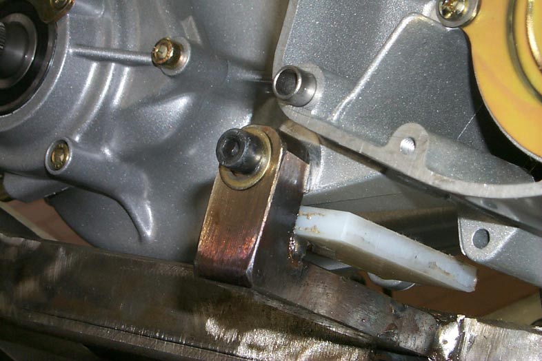


361 160 09/01
362 CONTROLLO - RIPARAZIONE - MANUTENZIONE KONTROLLE - REPARATUR - WARTUNG CHECKS REPAIRS MAINTENANCE CONTROLE - REPARATIONS - ENTRETIEN CONTROL - REPARACION - MANTENIMIENTO /01
363 CONTROLLO - RIPARAZIONE - MANUTENZIONE /KONTROLLE - REPARATUR - WARTUNG CONTROL - REPAIR - MAINTENANCE /CONTROLE - REPARATIONS - ENTRETIEN / CONTROL - REPARACION - MANTENIMIENTO Tabella cilindro - pistone / Tabelle Zylinder-Kolben / Table cylinder - piston / Tableau cylindre - piston / Tabla cilindro-pistón Particolare / T eil / Part / Pièce / Pieza C ilindro - Quota "E" / Z ylinder - Maß E" / Cylinder - Distance "E" / C ylindre - Cote "E" / Cilindro - Cota "E" P istone - Quota "C" / K olben - Maß C" / Piston - Distance "C" / Piston - C ote "C" / Pistón - Cota "C" Valori in mm / Werte in mm Value in mm / Valeurs en mm / Valores en mm 400cc Ø 86 Ø ±0.015 Fasce elastice de pistón / K olbenringe / Piston rings / Segments élastiques / Aros 1) Segmento di tenuta / D ichtring / Seal / Segment d'étanchéité / Aro de estanqueidad 2) Segmento di tenuta / D ichtring / Seal / Segment d'étanchéité / Aro de estanqueidad 3) Segmento raschiaolio / Ö labstreifring / Scraper / Segment racleur d'huile / Anillo raspador aceite Ø 86 x1 Ø 86 x 1 Ø 86 x N.B. Vedi figure pag. 161 / Merke: Siehe Abbildungen S. 161/ N.B. See figure on page 161 / Cf. les photos page 161 / N.B. Ver figuras pág. 161 Accoppiamento piede di biella - spinotto / Verbindung Pleuelkopf - Bolzen / Small end of connecting rod-piston pin coupling /Accouplement pied de bielle - axe de piston / Acoplamiento pie de biela-pasador de émbolo PIEDE DI BIELLA / PLEUELKOPF / SMALL END OF CONNECTING ROD / PIED DE BIELLE / PIE DE BIELA SPINOTTO/ B OLZEN / PISTON PIN / AXE DE PISTON / PASADOR DE EMBOLO Ø Piede di biella / Ø Pleuelkopf / Ø Small end of connecting rod / Ø Pied de bielle / Ø Pie de biela Ø Spinotto / Ø Bolzen / Ø Piston pin / Ø Axe de piston / Ø Pasador émbolo Ø 20 Ø , /01
364 Accoppiamenti Cilindro-Pistone/ Verbindung Zylinder-Kolben / Cylinder-piston coupling /Accouplements cylindre - piston / Acoplamientos Cilindro-Pistón SIGLA DI SELEZIONE WAHL-KENNZEICHEN SELECTING CODE SIGLE DE SELECTION SIGLA DE SELECCION CILINDRO ZYLINDER CYLINDER CYLINDRE CILINDRO PISTONE KOLBEN PISTON PISTON PISTON GIOCO DI MONTAGGIO / MONTAGESPIEL / CLEARANCE AT ASSEMBLY / JEU DE MONTAGE / JUEGO DE MONTAJE A B C Posizioni di controllo selezioni / Kontrollstellen Wahlen / Selection check points / Positions de contrôle sélections / Posiciones de control selecciones /01
365 Valvole Ventile - Verificare che le valvole non siano danneggiate (incrinate, bruciate o deformate). - Pulire le valvole rimuovendo i residui carboniosi. - Verificare il diametro dello stelo valvola «S». - Aspirazione= Scarico= Controllare lo stato della sede sul fungo valvola. N.B. Le misure vanno effettuate all estremità del campo di lavoro («N») dello stelo valvola e in più punti radialmente. 1) Quando si smontano le valvole è necessario sostituire i semiconi. Valves - Kontrollieren, dass die Ventile nicht beschädigt sind (rissig, durchgebrannt oder verformt). - Die Rückstände von den Ventilen wegputzen. - Durchmesser des Ventilschaftes «S» kontrollieren. - Ansaugung = Ablass = Zustand des Sitzes auf dem Ventilpilz kontrollieren. Merke: Die Messungen am Ende des Arbeitsfeldes («N») des Ventilschaftes und radial an mehreren Stellen durchführen. 1) Bei der Demontage der Ventile sind die Kegelstücke auszuwechseln. Soupapes Válvulas - Check the valves for damage (cracked, blown or deformed). - Clean the valves to remove carbon residues. - Check the diameter of the valve stem S. - Intake = Exhaust = Check the condition of the seat on the valve head. N.B. The measurements should be taken at the extremity of the working field ( N ) of the valve stem and in various radial positions. 1) Always replace the cotters when disassembling a valve. - Vérifier l état des soupapes (fêlures, brûlures ou déformations). - Nettoyer les soupapes en éliminant les résidus. - Vérifier le diamètre de la queue de la soupape «S». - Admission = de à Echappement = de à Contrôler l état du logement sur la tête de la soupape. N.B. Prendre les mesures à l extrémité du champ de travail («N») de la queue de la soupape et à plusieurs autres points radiaux. 1) Les demi-clavettes doivent être changées après chaque démontage. - Controlar que las válvulas no estén estropeadas (resquebrajadas, quemadas o deformadas). - Limpiar las válvulas eliminando los residuos carbonosos. - Controlar el diámetro del vástago válvula «S». - Admisión = Escape = Controlar el estado del asiento de la seta válvula. N.B. Las medidas deben realizarse en el extremo del campo de trabajo («N») del vástago de la válvula en varios puntos radialmente. 1) Cuando se montan las válvulas se deben cambiar los semiconos. AA PMS CS Regolazione valvole 1mm /Ventileinstellung 1 mm / Valve adjustment 1mm /Réglage soupapes 1mm / Regulación válvulas 1 mm FASE VALVOLE/ VENTILPHASEN / VALVE PHASES/ PHASES SOUPAPES / FASE VALVULAS AA= Apertura aspirazione / Öffnung Ansaugung / Open intake /Ouverture admission / Apertura admisión CA= Chiusura aspirazione /Schließung Ansaugung / Close intake /Fermeture admission / Cierre admisión CA AS AS= Apertura scarico / Öffnung Ablass / Open exhaust/ Ouverture échappement / Apertura escape PMI /01 CS= Chiusura scarico / Schließung Ablass / Close exhaust / Fermeture échappement / Cierre escape
366 Controllo sedi valvola sulla testa - Verificare che le sedi valvole non presentino tracce di lesioni o crepe. - Verifichiamo il diametro interno della guida valvola «G» - Aspirazione e scarico mm. Ø5 - Limite di misura mm Le misure vanno effettute all estremità del campo di lavoro. - Verificare la lunghezza dell impronta sulla sede valvola «V» con limite di misura 1.4 mm max. - Verificare l integrità del piano di lavoro della punteria sulla valvola (vedi dettaglio «A» e «B» figura sopra). 2) La verifica della tenuta delle valvole in mancanza dell apposita attrezzatura viene effettuata immettendo benzina nel condotto. Verificare se vi sono forti trafilamenti. La prova è conforme quando compare solo un alone di benzina. N.B. In caso di usure oltre i valori sopra indicati sostituire la testa con relative valvole. Kontrolle der Ventilsitze auf dem Kopf - Kontrollieren, dass die Ventilsitze keine Beschädigungen oder Risse aufweisen. - Den Innendurchmesser der Ventilführung «G» prüfen. - Ansaugung und Ablass Ø5 mm. - Messgrenze 5,022 mm. - Die Messungen am Ende des Arbeitsfeldes ausführen. - Länge des Abdruckes auf dem Ventilsitz «V» mit max. Messgrenze 1,4 mm prüfen. - Einwandfreien Zustand der Arbeitsfläche des Stössels auf dem Ventil kontrollieren (siehe «A» und «B» - obige Abb.). 2) Wenn das dazu dienende Werkzeug nicht vorhanden ist, wird die Dichtigkeit der Ventile durch Eingießen von Benzin in die Leitung geprüft. Prüfen, ob starke Durchsickerungen bestehen. Das Ergebnis stimmt, wenn nur ein Benzinschleier erscheint. Merke: Bei stärkerem Verschleiß als die obigen Werte, den Kopf mit den entsprechenden Ventilen auswechseln. Contrôle des sièges de soupape sur la culasse Checking valve seats on head - Check the valve seats for signs of damage or cracks. - Check the internal diameter of the valve guide G - Intake and exhaust Ø5mm - Measuring limit 5.022mm - Measurements should be taken at the extremity of the working field. - Check the length of the impression on the valve seat V using a max. measuring limit of 1.4mm - Check the integrity of the working surface of the tappets on the valve (see A and B in the figure above). 2) Check the tightness of the valve. In the absence of special tools pour petrol into the pipe and check for strong blow-by. The test is acceptable when only a halo of petrol forms. N.B. In f the valve is worn beyond the values indicated above, replace the head together with the relative valves. Control asientos válvula en la culata - Vérifier l état du siège de la soupape qui ne doit pas être fendu. - Vérifier le diamètre interne du guide de soupape «G». - Admission et échappement : Ø5 mm. - Limites de mesure : mm. - Les mesures doivent être prises à l extrémité du champ de travail. - Vérifier la longueur de l empreinte sur le siège de la soupape «V» avec une tolérance de 1.4 mm max. - Vérifier l état du plan de travail du poussoir sur la soupape (cf. dessins «A» et «B» ci-contre). 2) En absence de l outil spécial, la vérification de l étanchéité des soupapes s effectue en versant de l essence dans le conduit et en contrôlant les fuites. L essai est conforme si on ne voit apparaître qu un halo. N.B. Si l usure dépasse les valeurs sus-indiquées, changer la tête et les soupapes. - Controlar que los asientos de válvulas no presenten rastros de lesiones o grietas. - Controlar el diámetro interno de la guía válvula «G» - Admisión y escape mm. Ø5 - Límite de medida mm Las medidas deben realizarse en el extremo del campo de trabajo. - Controlar la longitud de la huella en el asiento válvula «V» con límite de medida 1.4 mm máx. - Controlar la integridad del plano de trabajo del alzaválvula en la válvula (ver detalle «A» y «B» figura anterior). 2) El control de las estanqueidad de las válvulas a falta del equipo correspondientese realiza poniendo gasolina en el conducto. Controlar si hay fugas grandes. La prueba es conforme cuando aparece sólo un halo de gasolina. N.B. Con desgastes superiores a los valores antedichos calbiar la culata con respectivas válvulas /01
367 CONTROLLI / KONTROLLEN / CHECKS / CONTROLES /CONTROLES Cilindro -Verificare che le superfici interne del cilindro non presentino grippaggi o usure anomale, misurare il diametro interno del cilindro con un alesametro. - Limite di usura mm 0.03 oltre la misura minima della selezione indicata - Eseguire la misura su tre piani lungo l asse del cilindro e per ogni piano eseguire la misurazione sulla circonferenza. Zylinder -Prüfen, dass die Innenflächen des Zylinders kein Fressen oder anomale Abnutzungen aufweisen, den Innendurchmesser des Zylinders mit dem entsprechenden Messgerät messen. - Abnutzungsgrenze: 0,03 mm über dem Mindestwert der angezeigten Wahl. - Messung auf drei Ebenen entlang der Zylinderachse durchführen und auf jeder Ebene den Umfang messen. Pistone -Smontare le fasce elastiche e verificare che il pistone non presenti usure anomale. N.B. Le fasce del pistone si rompono facilmente, porre attenzione allo smontaggio. Kolben -Die Kolbenringe abmontieren und prüfen, dass der Kolben keine anomalen Abnutzungen aufweist. Merke: Die Kolbenringe brechen leicht, daher bei der Abmontage vorsichtig vorgehen. - Misurare il gioco tra la fascia e la gola. Limite di usura: 0.08 max - Das Spiel zwischen Kolbenring und Rille messen. Abnutzungsgrenzwert: max. 0,08 - Misurare il foro dello spinotto sul pistone. Ø massimo ammesso mm. - Die Bolzenbohrung auf dem Kolben messen. +0,18 Max. zulässiger Ø: 20 mm /01
368 CONTROLLI / KONTROLLEN / CONTROLES /CONTROLES Cylinder - Check the internal surfaces of the cylinder for jamming or abnormal wear, measure the internal diameter of the cylinder using a bore gauge. - Wear limit = 0.03mm higher than the measurement of the minimum selection indication. - Take measurements on three different planes along the axis of the cylinder, measure the circumference at each plane. Cylindre -Vérifier si les surfaces internes du cylindre présentent des grippages ou une usure anormale, mesurer l alésage interne du cylindre avec un outil prévu à cet effet. - Limite d usure 0,03 mm au-delà de la mesure minimum de la sélection indiquée. - Effectuer la mesure sur 3 niveaux le long de l axe du cylindre. Pour chaque niveau effectuer la mesure de la circonférence. Cilindro - Controlar que las superficies internas del cilindro no presenten agarrotamientos o desgastes anómalos, medir el diámetro interno del cilindro con un medidor adecuado. - Límite de desgaste mm 0.03 más allá de la medida mínima de la selección indicada - Efectuar la medida en tres planos a lo largo del eje del cilindro y para cada plano efectuar la medida en la circunferencia. Piston - Disassemble the piston rings and check the piston for abnormal wear. N.B. The piston rings are fragile, handle with care. Piston - Démonter les segments élastiques et vérifier si le piston ne présente pas d usures anormales. Attention! Les segments du pistons se cassent facilement, faire attention au moment du démontage. Pistón -Desmontar los aros y comprobar que el pistón no presente desgastes anómalos. N.B. Los aros del pistón se rompen fácilmente, prestar atención durante el desmontaje. - Measure the clearance between the piston ring and the race. Wear limit: 0.08 max. - Mesurer le jeu entre le segment et la gorge. Tolérance maximum admise : 0,08 max - Medir el juego entre el aro y la garaganta. Límite de desgaste: 0.08 máx - Measure the piston pin hole on the piston. Max. permitted Ø mm - Mesurer l alésage de l axe de piston. Ø maximum admis: 20+0,18 mm. - Medir el agujero del pasador en el pistón. Ø máximo admitido mm /01

369 Spinotto - Misurare il diametro esterno dello spinotto. Diametro minimo ammesso ø mm. - Calcolare il gioco tra il pistone e spinotto. Gioco max dopo l uso mm Bolzen - Außendurchmesser des Bolzens messen. Zulässiger Mindestdurchmesser: ø mm. - Spiel zwischen Kolben und Bolzen berechnen. Max. Spiel nach Gebrauch: 0,020 mm. Piede di biella - Misurare il diametro interno del piede di biella Ø max ammesso 20 mm Pleuelkopf - Innendurchmesser des Pleuelkofes messen. +0,014 Max. zulässiger Ø: 20 mm. +0,003 Segmenti pistone - Introdurre ogni fascia nel cilindro nella zona di lavoro. Spingere le fasce con il pistone per garantire la perpendicolarità. - Misurare la distanza tra gli estremi della fascia. A= max 0.6 B= max 0.5 C= max 0.6 Montaggio fasce sul pistone - Porre attenzione a non danneggiare le fasce durante il montaggio e posizionarle come indicato in figura. Attenzione - Dopo il montaggio, le fasce devono poter girare liberamente nella propria sede. Attenzione - I segmenti A e B devono essere montati con le marcature N rivolte verso l alto Spinotto - pistone - Montare il pistone posizionando il riferimento SC dal lato delle valvole di scarico, inserire lo spinotto e montare anelli elastici nuovi. N.B. Verificare la corretta introduzione nella propria sede degli anellini. marcatura N piccola + smusso interno / Kleine Kennzeichnung N + Innenabschrägung / small N + internal bevel /empreinte N petite + arrondi interne / marca N pequeña + bisel interno /01 A Segmento prima cava / Kolbenring erste Nut / First slot / Segment première rainure / Segmento primer hueco marcatura N grande / große Kennzeichnung N / Large N / empreinte N grande / Marca N grande Kolbenringe - Jeden Ring im Arbeitsbereich in den Zylinder einführen. Die Ringe mit dem Kolben schieben, um die Rechtwinklichkeit zu sichern. - Abstand zwischen den Enden der Ringe messen. A= max. 0,6 B= max. 0,5 C= max. 0,6 Montage der Kolbenringe auf den Kolben - Aufpassen, dass die Kolbenringe bei der Montage nicht beschädigt werden und sie laut Abbildung positionieren. Achtung - Nach der Montage müssen die Kolbenringe frei in ihrem Sitz drehen können. Achtung - Die Kolbenringe A und B müssen mit den Buchstaben N nach oben gerichtet montiert werden. Bolzen - Kolben - Den Kolben montieren und dabei die Kennzeichnung SC von der Seite der Ablassventile positionieren, den Bolzen einführen und neue Kolbenringe montieren. Merke: Prüfen, dass die Ringe korrekt in ihren Sitz eingeführt wurden.

370 Piston pin - Measure the outer diameter of the piston pin. Minimum permitted diam. Ø19,994mm. - Calculated the clearance between the piston and the piston pin. Max. clearance after use 0.020mm. Axe de piston - Mesurer le diamètre externe de l axe de piston. Diamètre minimum admis ø mm. - Calculer le jeu entre le piston et l axe de piston. Jeu maximum après l utilisation mm. Pasador - Medir el diámetro externo del pasador. Diámetro mínimo admitido ø mm. - Calcular el juego entre el pistón y el pasador. Juego máx tras el uso mm Small end of connecting rod - Measure the internal diameter of the small end of the connecting rod. Max. permitted Ø 20 +0,014 +0,003 mm. Pied de bielle - Mesurer le diamètre interne du pied de bielle. Ø max admis 20 mm. +0,014 +0,003 Pie de biela - Medir el diámetro interno del pie de biela. +0,014 Ø máx admitido 20 mm +0,003 Piston rings - Place each ring in the cylinder in the working area. Push the rings using the piston to ensure they are perpendicular. - Measure the distance between the ends of the ring. A=max. 0.6 B= max 0.5 C= max 0.6 Assembling the rings on the piston - Take care not to damage the rings during assembly and position them as shown in the figure. Warning after assembly the rings should turn freely in their seats. Warning Rings A and B should be assembled with the N uppermost. Segments du piston - Introduire chaque segment dans le cylindre dans la zone de travail. Pousser les segments avec le piston pour garantir la perpendicularité. - Mesurer la distance entre les extrémités du segment. A = max 0.6 B = max 0.5 C = max 0.6 Montage des segments sur le piston - Faire attention à ne pas endommager les segments pendant le montage et les monter comme illustré dans le dessin. Attention - Après le montage, les segments doivent pouvoir tourner librement dans leur logement. Attention - Les segments A et B doivent être montés avec les empreintes N orientées vers le haut. Ars pistón - Introducir cada aro en el cilindro en la zona de trabajo. Empujar los aros con el pistón para garantizar la perpendicularidad. - Medir la distancia entre los extremos del aro. A= máx 0.6 B= máx 0.5 C= máx 0.6 Montaje aros en el pistón - Prestar atención en no dañar los aros durante el montaje y ponerlos como indicado en la figura. Atención - Tras el montaje, los aros deben poder girar libremente en su asiento. Atención - Los aros A y B se deben montar con las marcas N dirigidas hacia arriba Piston pin piston - Assemble the piston with the SC reference on the exhaust valve side. Insert the pin and assemble new piston rings. N.B. Check to make sure that the rings are correctly positioned in their seats. Axe de piston - piston - Monter le piston avec le repère SC du côté des soupapes d échappement, monter l axe de piston et les segments neufs. N.B. Vérifier l introduction des segments dans leur logement. Pasador - pistón - Montar el pistón colocando la refrerencia SC por el lado de las válvulas de escape, poner el pasador y montar aros nuevos. N.B. Verificar que sea correcta la introducción de los anillos pequeños en sus asientos /01


371 Apertura pompa olio - Smontare le due viti di fissaggio parte posteriore pompa. Öffnen der Ölpumpe - Die zwei Befestigungsschrauben auf der Pumpenrückseite losschrauben. Smontare seeger pompa olio - Smontare l anello elastico di ritegno rotore. N.B. Procedere ad un accurato lavaggio con benzina e aria compressa Demontage Seegerring der Ölpumpe - Den Seegerring des Rotors abmontieren. Merke: Sorgfältig mit Benzin und Druckluft reinigen. Verificare gioco rotore esterno - Misurare il gioco del rotore esterno con il corpo pompa secondo gli assi come in figura. Limite di usura mm Prüfung des Spiels des äußeren Rotors - Das Spiel des äußeren Rotors mit dem Pumpengehäuse nach den Achsen laut Abbildung messen. Abnutzungsgrenze: 0,09 mm. Verifica del gioco tra rotori - Misurare il gioco tra rotore interno e rotore esterno. Limite di usura mm Oltre questa misura sostituire la pompa. Prüfung des Spiels zwischen den Rotoren - Das Spiel zwischen dem internen und externen Rotor messen. Abnutzungsgrenze: 0,12 mm. Nach Überschreitung dieses Maßes die Pumpe auswechseln /01
372 Opening the oil pump - Remove the two fastening screws on the back of the pump. Ouverture de la pompe à huile - Démonter les 2 vis de fixation de la partie arrière de la pompe. Apertura bomba aceite - Desmontar los dos tornillos de fijación parte trasera bomba. Removing the oil pump snap ring - Remove the rotor retaining ring. N.B. Wash thoroughly using petrol and compressed air. Démontage du jonc de la pompe à huile - Démonter le jonc élastique qui retient le roto. N.B. Nettoyer soigneusement avec de l essence et de l air comprimé. Desmontar seeger bomba aceite - Desmontar el anillo elástico de retén rotor. N.B. Proceder a un lavado a fondo con gasolina y aire comprimido Check outer rotor clearance - Measure the clearance between the outer rotor and the pump case at the axes shown in the figure. Wear limit 0.09mm. Vérification du jeu du rotor externe - Mesurer le jeu du rotor externe avec le corps de la pompe selon les axes illustrés dans le dessin. Tolérance maximum admise : 0.09 mm. Verificar juego rotor externo - Medir el juego del rotor externo con el cuerpo bomba según los ejes como en la figura. Límite de desgaste mm Check clearance between rotors - Measure the clearance between the inner and outer rotors. Wear limit 0.12mm Beyond this quantity the pump must be replaced. Vérification du jeu entre les rotors - Mesurer le jeu entre le rotor interne et le rotor externe. Tolérance maximum admise : 0.12 mm. Changez la pompe au-delà de cette mesure. Control del juego entre rotores - Medir el juego entre rotor interno y rotor externo. Límite de desgaste mm Más allá de esta medida cambiar la bomba /01

 devono essere posizionati verso la parte posteriore pompa come indicato in figura.")
 müssen wie in der Abbildung gezeigt in Richtung Pumpenrückseite positioniert sein.")


373 Verificare gioco rotorecorpo pompa - Misurare il gioco tra il corpo pompa e rotore. Limite di usura mm Prüfung des Spiels zwischen Rotor- Pumpengehäuse - Das Spiel zwischen Pumpengehäuse und Rotor messen. Abnutzungsgrenze: 0,20 mm. Alberino rotore interno - Montare l anello elastico avendo cura di posizionarlo nella propria sede. Attenzione - I riferimenti (indicati in figura) devono essere posizionati verso la parte posteriore pompa come indicato in figura. Innere Rotorwelle - Den Seegerring sorgfältig in seinen Sitz montieren. Achtung - Die Kennzeichen (siehe Abbildung) müssen wie in der Abbildung gezeigt in Richtung Pumpenrückseite positioniert sein. Chiusura pompa olio - Rimontare la parte posteriore della pompa facendo attenzione al corretto montaggio dell anello seeger. Schließen der Ölpumpe - Die Rückseite der Pumpe wieder montieren und dabei darauf achten, dass der Seegerring korrekt montiert ist. Pompa olio - Inserire la guarnizione - Rimontare la pompa nel proprio alloggio rispettando la coppia di serraggio prescritta N.B. I fori di fissaggio sono disassati, pertanto è impossibile sbagliare il montaggio. N.B. Al montaggio impiegare sempre guarnizioni nuove. Avvertenza - Coppia critica: è assolutamente necessario rispettare la coppia prescritta. Coppia di bloccaggio 5 6 Nm con LOCTITE 222 A montaggio ultimato, verificare che la pompa giri normalmente ed in modo regolare. Ölpumpe - Dichtung einlegen. - Die Pumpe wieder in ihre Aufnahme einbauen und dabei das vorgeschriebene Anzugsmoment einhalten. Merke: Die Befestigungslöcher sind achsungleich; daher ist eine falsche Montage nicht möglich. Merke: Bei der Montage immer neue Dichtungen verwenden. Hinweis - Kritisches Moment: Es ist unbedingt notwendig, das vorgeschriebene Moment einzuhalten. Sperrmoment: 5 6 Nm mit LOCTITE 222 Nach vollendeter Montage prüfen, dass die Pumpe normal und regelmäßig dreht /01
374 Check rotor-pump case clearance - Measure the clearance between the pump case and the rotor. Wear limit 0.20mm. Vérification du jeu rotor - corps pompe - Mesurer le jeu entre le coprs de la pompe et le rotor. Tolérance maximum admise : 0.20mm. Controlar juego rotorcuerpo bomba - Medir el juego entre el cuerpo bomba y rotor. Límite de desgaste mm Inner rotor spindle - Assemble the snap ring taking care to position it correctly in its seat. Warning The reference points (shown in the figure) must be placed towards the back of the pump as indicated in the figure. Axe rotor interne - Monter le jonc élastique dans son logement. Attention - Les repères (indiqués sur le dessin) doivent être placés avec le repère vers la partie arrière de la pompe comme illustré sur le dessin. Eje rotor interno - Montar el anillo elástico procurando ponerlo en su asiento. Atención- Las referencias (indicadas en figura) se deben colocar hacia la parte trasera de la bomba como mostrado en la figura. Closing the oil pump - Re-assemble the back of the pump taking care to assemble the snap ring correctly. Fermeture de la pompe à huile - Remonter la partie arrière de la pompe en veillant à monter correctement le jonc. Cierre bomba aceite - Montar de nuevo la parte trasera de la bomba prestando atención en el montaje correcto del anillo seeger. Oil pump - Insert the gasket - Re-assemble the pump in its housing using the recommended tightening torque. N.B. The screw holes are misaligned, it is therefore impossible to assemble the pump incorrectly. N.B. Always use new gaskets when re-assembling the pump. Warning Critical torque: it is essential to use the recommended tightening torque. Locking torque 5-6Nm plus LOCTITE 222 After assembling the pump check that it turns correctly. Pompe à huile - Introduire le joint. - Remonter la pompe dans son logement en respectant le couple de serrage prévu. N.B. Les trous de fixation sont désaxés, il est donc impossible de se tromper dans le montage. N.B. Utiliser des joints neufs à chaque montage. Attention - couple critique : le couple prévu doit absolument être respecté. Couple de serrage : de 5 à 6 Nm avec LOCTITE 222 Après le montage, vérifier la rotation de la pompe. Bomba aceite - Poner la guarnición - Montar de nuevo la bomba en su alojamiento respetando el par de apriete prescrito N.B. Los agujeros de fijación están desalineados, por lo tanto es imposible equivocarse en el montaje. N.B. En el montaje utilizar siempre guarniciones nuevas. Advertencia - Par crítico: es terminantemente necesario respetar el par prescrito. Par de apriete 5 6 Nm con LOCTITE 222 Terminado el montaje controlar que la bomba gire normalmente y con regularidad /01


375 Controllo dell albero motore - Verificare il gioco laterale della testa di biella con uno spessimetro. Gioco massimo mm Gioco minimo mm Kontrolle der Motorwelle - Das Seitenspiel des Pleuelkopfes mit einem Dickenmesser kontrollieren. Max. Spiel: 0,55 mm. Min. Spiel: 0,15 mm. Verificare gioco radiale - Verificare il gioco radiale della testa di biella nei due punti perpendicolari all albero. Gioco min mm max (senza olio). Kontrolle des radialen Spieles - Das radiale Spiel des Pleuelkopfes an den senkrecht zur Welle verlaufenden Stellen prüfen. Min. Spiel: 0,045 mm; max. Spiel: 0,065 mm (ohne Öl). Verificare disassamento ammesso albero motore - Posizionare l albero motore sull attrezzo specifico e rilevare il disassamento tra i due semialberi. Max disassamento ammesso 0.15 mm. Prüfung der zulässigen Fluchtabweichung der Motorwelle - Die Motorwelle auf das entsprechende Werkzeug setzen und die Fluchtabweichung zwischen den zwei Halbwellen messen. Max. zulässige Fluchtabweichung: 0,15 mm /01
376 Checking the driving shaft - Check the clearance on the side of the connecting rod using a thickness gauge. Max. clearance 0.55mm Min. clearance 0.15mm Contrôle de l arbre moteur - Vérifier le jeu latéral de la tête de bielle avec un épaisseurmètre. Jeu maximum admis : 0.55 mm. Jeu minimum admis : 0.15 mm. Control del eje motor - Controlar el juego lateral de la cabeza de biela con un medidor de galgas. Juego máximo mm Juego mínimo mm Check the radial clearance - Check the radial clearance of the big end of the connecting rod at the two points perpendicular to the shaft. Clearance: min mm, max mm (without oil). Vérification du jeu radial - Vérifier le jeu radial de la tête de bielle aux deux endroits perpendiculaires à l arbre. Jeu maximum admis : mm. Jeu minimum admis : mm. (sans huile). Control del juego radial - Controlar el juego radial de la cabeza de biela en los dos puntos perpendiculares al eje. Juego mínimo mm máximo (sin aceite). Check permitted misalignment of driving shaft - Place the driving shaft on the measuring tool and check the misalignment between the two shafts. Max. permitted misalignment 0.15mm. Vérification du désaxage de l arbre moteur - Placer l arbre moteur sur l outil prévu à cet effet et relever le désaxage sur les 2 demi-arbres. Désaxage maximum admis : 0.15 mm. Control del desplazamiento de ejes admitido para el eje motor - Colocar el eje motor en la herramienta específica y registrar el desplazamiento de ejes entre los dos semiejes. Desplazamiento de ejes máximo admitido 0.15 mm /01


/ M OTORWELLE ( E INZIGE WAHL ) / DRIVING SHAFT ( S INGLE SELECTIO N) / ARBR E MOTEUR ( S ÉLECTION UNIQUE) / EJE MOTOR ( S ELECCÓN")
377 Gioco di funzionamento tra bronzina assemblata ed albero Betriebsspiel zwischen dem montierten Bronzelager und der Welle / Running clearance between assembled bushing and shaft / Jeu de fonctionnement entre le coussinet assemblé et l arbre / Juego de funcionamiento entre buje ensamblado y eje BRONZINA BRONZELAGER/ BUSHING / COUSSINET / BUJE BRONZINA BRONZELAGER BUSHING/ COUSSINET/ BUJE INSERTO DI BANCO LAGERAUFNAHME BED INSERT/ LOGEMENT COUSSINET/ SOPORTE PRINCIPAL INSERTO DI BANCO LAGERAUFNAHME BED INSERT/ LOGEMENT COUSSINET/ SOPORTE PRINCIPAL SELEZIONI BRONZINE / BRONZELAGER W AHL / BUSHING SELECTION / SELECTION COUSSINETS / SELECCIÓN BUJES Rosso/ R o/ tred / Roug e/ Roj o Blu/ B lau/ Blue/ Bleu/Blu SELEZIONI SEMICARTER / GEHÄUSEHÄLFT E W AHL / HALF-CASE SELECTION / SELECTION SEMI-CARTER / SELECCIÓ N SEMICARTER CEDIMENTO MEDIO SED E/ DURCHSCHNITTLICHE VERFORMUNG DES S ITZES / A VERAGE SEAT YIELD/ DéFORMATION MOYENNE DU LOGEMENT D U COUSSINET / DEFORMACIóN MEDIA ALOJAMIENTO 0.011mm ALBERO MOTORE (SELEZIONE UNICA)/ M OTORWELLE ( E INZIGE WAHL ) / DRIVING SHAFT ( S INGLE SELECTIO N) / ARBR E MOTEUR ( S ÉLECTION UNIQUE) / EJE MOTOR ( S ELECCÓN ÚNICA) GIOCO RADIALEALBERO MOTORE/ MOTORWELLE RADIALES SPIEL / DRIVING SHAFT RADIAL CLEARANCE/ JEU RADIAL ARBRE MOTEUR / JUEGO RADIAL EJE MOTOR /01
378 Livello olio motore - A motore freddo e veicolo posizionato su di una superficie piana, su cavalletto. - Controllare il livello dell olio sulla spia sul carter. - Se il livello è prossimo al minimo e l olio non deve essere sostituito (vedi tabella manutenzione), effettuare il rabbocco con il tipo di olio consigliato. Immettere il quantitativo max. indicato (2200 cc.); il livello dell olio risulterà a metà della spia sul carter. Motorölstand - Die Kontrolle auf dem kalten Motor durchführen und dabei den Motorroller auf einem ebenflächigen Boden auf den Ständer stellen. - Den Ölstand an der Ölstandsanzeige auf dem Gehäuse kontrollieren. - Wenn der Ölstand fast am Minimum ist und kein Ölwechsel erforderlich wäre (siehe Wartungsprogramm), den empfohlenen Öltyp nachfüllen. Die vorgegebene Höchstmenge (2200 cl) einfüllen; der Ölstand wird bis zur Mitte der Ölstandsanzeige auf dem Gehäuse reichen. Engine oil level With the engine cold and the vehicle on its stand on a flat surface: - check the oil level through the inspection window on the case. - if the level is near the minimum mark and the oil does not need to be changed (see maintenance table), top-up with the recommended type of oil. Pour the maximum recommended quantity of oil (2200cc) into the oil sump; the oil level will now be halfway up the inspection window on the case. Niveau huile moteur - Ce contrôle doit être effectué lorsque le moteur est froid et le motocycle placé sur sa béquille et un sol plat. - Contrôler le niveau sur la jauge du carter. - Si le niveau est proche du minimum et l huile n a pas besoin d être changée (cf. tableau entretien), faire l appoint avec la marque d huile conseillée. Verser la quantité maximum indiquée (2.200 cl). Le niveau doit se situer à moitié de la jauge sur le carter. Nivel aceite motor - Con el motor frío y la moto colocada en una superficie plana, sobre caballete. - Controlar el nivel del aceite por la mirilla en el cárter. - Si el nivel está próximo al mínimo y no se debe cambiar el aceite (ver tabla de mantenimiento), restablecer el nivel añadiendo aceite del tipo aconsejado. Introducir la cantidad máx. indicada (2200 cc.); el nivel del aceite quedará a mitad de la mirilla en el cárter /01
.")


379 Cambio olio - Effettaure il cambio dell olio a motore caldo. - Porre un recipiente sotto la coppa olio e rimuovere il tappo di scarico olio. - Dopo aver effettuato lo scarico dell olio è necessario pulire il filtro a rete accessibile rimuovendo il tappo 1 (vedi figura). - Dopo quest ultima operazione è necessario rimontare il filtro e serrare il tappo olio alla coppia prescritta usando un nuovo anello O- ring. Coppia di bloccaggio N.m. Serrare successivamente il tappo scarico olio. Coppia di serraggio N.m. Ölwechsel - Den Ölwechsel durchführen, wenn der Motor warm ist. - Einen Behälter unter die Ölwanne setzen und den Ölablasspropfen entfernen. - Das Öl auslassen und danach den Netzfilter reinigen, zu dem durch Entfernen des Stopfens 1 (siehe Abbildung) Zugriff besteht. - Danach muss der Filter wieder montiert, ein neuer O-Ring eingesetzt und der Ölablasspfropfen mit dem vorgeschriebenen Anzugsmoment wieder festgespannt werden. Anzugsmoment N.m. Danach den Ölablasspropfen festspannen. Anzugsmoment N.m. Changement d huile - Le changement d huile doit être effectué lorsque le moteur est chaud. - Placer un récipient d une capacité adéquate sous le carter d huile et dévisser le bouchon de vidange. - Après avoir vidangé l huile, nettoyer le filtre qui est accessible après avoir dévissé le bouchon 1 (cf. dessin). - Remonter le filtre après l avoir nettoyé. Remonter le bouchon avec un nouveau joint torique et visser au couple prévu. Couple de serrage : de 25 à 28 N.m. Revisser ensuite le bouchon de vidange. Couple de serrage : de 25 à 28 N.m. Changing the oil - Change the oil when the engine is hot. - Place a receptacle under the oil sump and remove the oil drainage plug. - Once all the oil has drained out clean the mesh filter (remove cap 1 as shown in the figure). - Replace the filter and the oil cap, tighten the cap using the recommended tightening torque and a new O-ring. Clamping torque 25-28Nm. Tighten the oil drainage plug. Tightening toque 25-28Nm. Cambio del aceite - Efectuar el cambio del aceite con el motor caliente. - Poner un recipiente debajo del cárter y quitar el tapón de vaciado del aceite. - Tras haber vaciado el aceiite es necesario limpiar el filtro de rejilla al que se accede quitando el tapón 1 (ver la figura). - Después de esta última operación se debe montar de nuevo el filtro y apretar el tapón en el cárter con el par de apriete prescrito y utilizando una nueva junta tórica. Par de apriete N.m. Seguidamente apretar el tapón de vaciado aceite. Par de apriete N.m /01
380 IMPIANTO DI LUBRIFICAZIONE / SCHMIERANLAGE / LUBRICATING SYSTEM CIRCUIT DE LUBRIFICATION / SISTEMA DE LUBRICACION BY-PASS / BYPASS / BYPASS / BY-PASS / BY- PASS /01
381 Gradi di variazione anticipo /Verstellbereich in Graden / Spark advance variation degree / Degrés de variation avance / Grados de variación avance ANTICIPO MOTORE / ZÜNDVERSTELLUNG / SPARK ADVANCE AVANCE ALLUMAGE / AVANCE MOTOR RPM X 1000 Giri/1 / X 1000 Upm / x 1000 rpm / X t/mn / X 1000 RPM * Inizio intervento limitatore 8600 giri /*Begrenzungsbeginn 8600 Upm / * The limiting device intervenes at 8600 rpm / *Intervention limiteur t/mn /* Inicio intervención limitador 8600 rpm * BTDC RPM *BTDC Con motore in moto, puntare pistola strobo in corrispondenza tappo ispezione fase posto sulla parte posteriore del coperchio volano. I riferimenti sono: tacca di riferimento su rotore volano tacca di riferimento su coperchio volano Bei laufendem Motor die Zündlichtpistole auf den Phaseninspektionsstopfen auf dem hinteren Teil des Schwungraddeckels richten. Die Bezugspunkte sind: Bezugskerbe auf dem Schwungradrotor Bezugskerbe auf dem Schwungraddeckel Curva variazione anticipo accensione / Kurve des Verstellbereichs der Zündung / Spark advance variation curve / Courbe variation avance à l allumage / Curva variación avance encendido Avec le moteur en marche, pointer le pistolet stroboscopique en correspondance du bouchon d inspection des phases situé à l arrière du couvercle du volant. Les repères sont : l encoche sur le rotor du volant, l encoche sur le couvercle du volant. With the engine running point the stroboscopic gun at the phase inspection cap on the back of the flywheel cover. The reference marks are: notch on flywheel rotor Con motor en marcha, apuntar la pistola estrobo hacia el tapón de inspección fase situado en la parte trasera de la tapa volante. Las referencias son: muesca de referencia en rotor volante muesca de referencia en tapa volante /01

382 CARBURATORE /VERGASER /CARBURETTOR CARBURATEUR / CARBURADOR Per la regolazione del minimo agire sulla vite 7. Per ottenere un minimo ottimale portare la vite a battuta e allentare di un giro completo. Minimo da 1500 a 1600 RPM Zur Leerlaufeinstellung auf die Schraube 7 einwirken. Für einen optimalen Leerlauf die Schraube bis zum Anschlag bringen und um eine ganze Umdrehung lockern. Leerlauf von 1500 bis 1600 RPM. For idle tuning adjust screw 7. For optimum idle tuning tighten the screw until it touches and then unscrew it by one full turn. Slow running from 1500 to 1600 RPM. Pour régler le ralenti, intervenez sur la vis 7. Pour un ralenti optimal, amenez la vis en contact et dévissez d un tour complet. Ralenti de 1500 à 1600 t/mn. Para el ajuste del ralentí actuar sobre el tornillo 7. Para conseguir un ralentí óptimo llevar el tornillo a tope y aflojar de una vuelta completa. Ralentí de 1500 a 1600 RPM /01
 /KONISCHE SCHWIMMERNADEL / JET NEEDLE / POINTEAU / ALFILER CONICO 5 GETTO DEL MINIMO /LEERLAUFDREHZAHLDÜSE /")
383 1 GETTO DEL MASSIMO / HÖCHSTDREHZAHLDÜSE / MAXIMUM JET /GICLEUR REGIME MAXIMUM / INYECTOR DEL MAXIMO 2 ATOMIZZATORE / EINSPRITZDÜSE / ATOMISER /ATOMISEUR / PULVERIZADOR 3 POLVERIZZATORE (Needle Jet) / ZERSTÄUBER / NEEDLE JET / PULVERISATEUR / PULVERIZADOR 4 SPILLO CONICO (Jet Needle) /KONISCHE SCHWIMMERNADEL / JET NEEDLE / POINTEAU / ALFILER CONICO 5 GETTO DEL MINIMO /LEERLAUFDREHZAHLDÜSE / IDLING JET / GICLEUR RALENTI / INYECTOR DEL RALENTI 6 OR GETTO MINIMO / O-RING LEERLAUFDREHZAHLDÜSE / IDLING JET O-RING/ JOINT TORIQUE / OR INYECTOR RALENTI 7 VITE REGOLAZIONE MISCELA (minimo) / EINSTELLSCHRAUBE DER KRAFTSTOFFÖLMISCHUNG (Leerlauf) / MIXTURE ADJUSTING SCREW (idling)/vis REGLAGE MELANGE (ralenti) / TORNILLO AJUSTE MEZCLA (ralentí) 8 MOLLA / FEDER / SPRING/ RESSORT / MUELLE 9 OR / O-RING / O-RING / JOINT TORIQUE / OR 10 MISCELATORE /MISCHER / MIXER / MELANGEUR / MEZCLADOR 11 OR / O-RING / O-RING / JOINT TORIQUE / OR 12 RONDELLA / UNTELEGSCHEIBE / WASHER / RONDELLE / ARANDELA 13 VALVOLA A DEPRESSIONE / UNTERDRUCKVENTIL / VACUUM VALVE / CLAPET DE DEPRESSION / VALVULA DE DEPRESION 14 ANELLO SEEGER / SEEGERRING / SNAP RING / JONC / SEEGER 15 OR / O-RING / O-RING / JOINT TORIQUE / OR 16 MEMBRANA / MEMBRAN / DIAPHRAGM / MEMBRANE / MEMBRANA 17 ANELLO BLOCCAGGIO MEMBRANA / MEMBRANSPERRRING / DIAPHRAGM CLAMPING RING / BAGUE FIXATION MEMBRANE / ARO BLOQUEO MEMBRANA 18 VITI FISSAGGIO ANELLO / RINGBEFESTIGUNGSSCHRAUBEN / RING FASTENING SCREW / VIS FIXATION BAGUE / TORNILLO FIJACION ARO 19 RONDELLA /UNTERLEGSCHEIBEN / WASHER / RONDELLE / ARANDELA 20 COPERCHIO CARBURATORE / VERGASERDECKEL / CARBURETTOR HOUSING / COUVERCLE CARBURATEUR / TAPA CARBURADOR 21 VITI FISSAGGIO COPERCHIO / DECKELBEFESTIGUNGSSCHRAUBEN / HOUSING FASTENING SCREW / VIS FIXATION COUVERCLE TORNILLOS FIJACION TAPA 22 MOLLA PER VALVOLA A DEPRESSIONE / FEDER FÜR UNTERDRUCKVENTIL / SPRING FOR VACUUM VALVE RESSORT POUR CLAPET DE DEPRESSION / MUELLE PARA VALVULA DE DEPRESION 23 VALVOLA ACCELERATORE / BESCHLEUNIGERVENTIL / ACCELERATOR VALVE / SOUPAPE ACCELERATEUR / VALVULA ACELERADOR 24 SUPPORTO VALVOLA ACCELERATORE / BESCHLEUNIGERVENTILHALTER / ACCELERATOR VALVE SUPPORT / SUPPORT SOUPAPE ACCELERATEUR / SOPORTE VALVULA ACELERADOR 25 VITI FISSAGGIO VALVOLA / VENTILBEFESTIGUNGSSCHRAUBEN / VALVE FASTENING SCREW / VIS FIXATION SOUPAPE / TORNILLO FIJACION VALVULA 26 RONDELLA /UNTERLEGSCHEIBE / WASHER / RONDELLE / ARANDELA 27 PIASTRINO INF. COMANDO ACCELERATORE / UNT. PLATTE BESCHLEUNIGERSTEUERUNG / LOWER ACCELERATOR PLATE / PLAQUETTE INF. COMMANDE ACCELERATEUR / PLAQUETA INF. MANDO ACELERADOR 28 PIASTRINO SUP. COMANDO ACCELERATORE / OBERE PLATTE BESCHLEUNIGERSTEUERUNG / TOP ACCELERATOR PLATE PLAQUETTE SUP. COMMANDE ACCELERATEUR / PLAQUETA SUP. MANDO ACELERADOR 29 RONDELLA /UNTERLEGSCHEIBE / WASHER / RONDELLE / ARANDELA 30 DADO COMANDO ACCELERATORE / MUTTER BESCHLEUNIGERSTEUERUNG / ACCELERATOR NUT / ECROU COMMANDE ACCELERATEUR /TUERCA MANDO ACELERADOR /01

384 31 LEVA COMANDO ACCELERATORE / BESCHLEUNIGER-STEUERHEBEL / ACCELERATOR LEVER / LEVIER COMMANDE ACCELERATEUR / PALANCA MANDO ACELERADOR 32 VITI /SCHRAUBEN / SCREWS / VIS / TORNILLOS 33 RONDELLE SPEZZATE / C-FÖRMIGE SCHEIBEN / SPLIT WASHERS / RONDELLES EN FORME DE C / ARANDELAS PARTIDAS 34 VITE REGOLAZIONE MINIMO /LEERLAUF-EINSTELLSCHRAUBE / IDLE TUNING SCREW / VIS REGLAGE RALENTI / TORNILLO AJUSTE RALENTI 35 MOLLA COMANDO ACCELERATORE /BESCHLEUNIGER-STEUERFEDER / ACCELERATOR SPRING / RESSORT COMMANDE ACCELERATEUR / MUELLE MANDO ACELERADOR 39 VITE DI CHIUSURA /VERSCHLUSSSCHRAUBE / CLOSING SCREW / VIS DE FERMETURE / TORNILLO DE CIERRE 40 GALLEGGIANTE /SCHWIMMER / FLOAT / FLOTTEUR / FLOTADOR 41 PERNO GALLEGGIANTE / SCHWIMMERZAPFEN / FLOAT PIN / AXE FLOTTEUR /PERNO FLOTADOR 42 SPILLO GALLEGGIANTE /SCHWIMMERNADEL / FLOAT NEEDLE / POINTEAU FLOTTEUR /ALFILER FLOTADOR 43 MOLLA DI TENUTA /DICHTFEDER/RESSORT COMPRESSION FLOTTEUR / SEAL SPRING / MUELLE DE RETENCION 44 VASCHETTA CARBURANTE /TREIBSTOFFSCHALE / FUEL TANK / CUVETTE CARBURANT/ PILETA CARBURANTE 45 MOLLA PER BLOCCO VASCHETTA /SCHALENSPERRFEDER / TANK SECURING SPRING / RESSORT FIXATION CUVETTE / MUELLE PARA BLOQUEO PILETA 46 GUARNIZIONE VASCHETTA /SCHALENDICHTUNG / TANK GASKET / JOINT CUVETTE / GUARNICION PILETA 47 REGOLATORE STARTER / STARTER-REGLER / STARTER REGULATOR / REGULATEUR STARTER / REGULADOR STARTER 48 CORPO CHIUSURA STARTER /STARTERGEHÄUSE / STARTER HOUSING / CORPS FERMETURE STARTER / CUERPO CIERRE STARTER 49 RONDELLA /UNTERLEGSCHEIBE / WASHER / RONDELLE / ARANDELA 50 GUARNIZIONE CORPO CHIUSURA STARTER /STARTERGEHÄUSEDICHTUNG / STARTER HOUSING GASKET / JOINT CORPS FERMETURE STARTER / GUARNICION CUERPO CIERRE STARTER 51 VITI /SCHRAUBEN / SCREWS / VIS / TORNILLOS 52 LEVA COMANDO STARTER /STARTER-STEUERHEBEL / STARTER LEVER / LEVIER COMMANDE STARTER / PALANCA MANDO STARTER 52 a STAFFA COMANDO STARTER /STARTER-STEUERBÜGEL / STARTER BRACKET / ETRIER COMMANDE STARTER / SOPORTE MANDO STARTER 52 b MOLLA DI RITORNO STARTER /STARTER-RÜCKZUGSFEDER / STARTER RETURN SPRING / RESSORT DE REFOULEMENT / MUELLE DE RETORNO STARTER 53 DADO /MUTTER / NUT / ECROU / TUERCA /01
385 VARIATORE ANTERIORE /VORDERER WANDLER / FRONT VARIABLE-SPEED DRIVE VARIATEUR AVANT / VARIADOR DELANTERO Smontaggio semipuleggia mobile /Abmontage der mobilen Halbscheibe / Disassembling the mobile halfpulley /Démontage de la semi-poulie mobile /Desmontaje semipolea móvil 1) Rimuovere distanziale semipuleggia (6) /Abstandhalter der Halbscheibe entfernen (6)/ 1) Remove the half-pulley spacer (6)/Démonter l entretoise de la semi-poulie. / Quitar espaciador semipolea (6) 2) Rimuovere coperchio disco contenimento rulli (2) svitando le viti (1) /Deckel der Rollenplatte entfernen (2)/ 1) Remove the cover of the disk containing the rollers (2) by unscrewing the screws (1)/ Démonter le couvercle du disque contenant les roulements / Quitar tapa disco contención rodillos (2) desenroscando los tornillos (1) 3) Estrarre il disco contenimento rulli (3) /Rollenplatte herausnehmen (3)/ Extract the disk containing the rollers (3)/ Démonter le disque contenant les roulements / Sacar el disco contención rodillos (3) 4) Togliere rulli variatore (7) /Wandlerrollen herausnehmen (7)/ Remove the variable-speed drive rollers (7)/ Enlever les roulements du variateur / Quitar rodillos variador (7) 5) Rimuovere i due anelli di tenuta (5) e (9) /Die zwei Dichtringe (5) u. (9) entfernen / Remove the two gas rings (5) and (9)/ Enlever les deux bagues d étanchéité (5) et (9) / Quitar los dos anillos de cierre (5) y (9) Controlli /Kontrollen/ Checks / Contrôles/ Controles Rulli variatore: controllare che siano esenti da ammaccature e che non presentino usure anomale. In presenza di tali difetti sostituire i rulli/wandlerrollen: Kontrollieren, dass sie keine Beulen oder anomale Abnutzungen aufweisen. Bei solchen Fehlern die Rollen auswechseln/ Variable-speed drive rollers: check that they are not dented or show signs of abnormal wear in which case they must be replaced / Roulements variateur : contrôler leur état et leur usure et les changer en cas de besoin. / Rodillos variador: controlar que no estén abollados y que no presenten defectos. Ante defectos cambiar los rodillos Semipuleggia fissa e mobile: controllare che le zone a contatto con la cinghia siano esenti da colorazioni causa surriscaldamento della cinghia/ Fixe und mobile Halbscheibe: Kontrollieren, dass die Riemenkontaktbereiche keine Färbungen aufgrund der Riemenüberhitzung aufweisen/ Fixed and mobile half-pulley: check that the areas that make contact with the belt are not coloured due to the belt overheating /Semi-poulie fixe et mobile : contrôler si les zones en contact avec la courroie ne sont pas colorées ce qui signifierait une surchauffe de la courroie. / Semipolea fija y móvil: controlar que las zonas en contacto con la correa no presenten coloraciones debidas a recalentamiento de la correa Controllare che i semiconi siano esenti da abrasioni. Max abrasione consentita 0.4 mm/ Kontrollieren, dass die Kegelstücke keine Reibstellen aufweisen. Max. zulässige Abreibung 0.4 mm / Check that the cotters are not scored. Max. permitted abrasion 0.4mm / Contrôler l usure des semiclavettes, usure maximale admise : 0,4 mm / Controlar que los semiconos no presenten abrasiones. Abrasión máx. consentida 0.4 mm Assemblaggio /Zusammenbau/ Assembly /Assemblage /Montaje Seguire il senso inverso della smontaggio osservando le seguenti istruzioni:/ In umgekehrter Abmontage-Reihenfolge vorgehen und die folgenden Anleitungen befolgen:/ Carry out the disassembly operations in reverse order as well as the instructions below: / Effectuer les opérations de démontage en sens inverse en suivant les prescriptions suivantes : / Seguir orden inverso al de desmontaje ajustándose a las instrucciones siguientes: 1) Applicare una piccola dose di grasso nel foro e sui paraoli/1) Eine kleine Schmierfettmenge in die Bohrung und auf die Ölabdichtungen auftragen / 1) Apply a small shot of grease to the hole and the oil retainers / 1) Appliquer une petite quantité de graisse dans l alésage et sur les bagues pare-poussière / Aplicar una pequeña cantidad de grasa en el agujero y en los guardagotas ATTENZIONE!!! Non eccedere con il grasso. Non applicare il grasso sulle superfici a contatto con la cinghia./ ACHTUNG!!! Nicht zu viel Fett auftragen. Das Fett nicht auf die Kontaktflächen mit dem Riemen auftragen./ WARNING!!! Do not over-grease. Do not grease surfaces that come into contact with the belt. / ATTENTION! Ne pas appliquer trop de graisse, ne pas en appliquer sur les surfaces en contact avec la courroie. / ATENCION! No exceder con la grasa. No aplicar la grasa sobre las superficies en contacto con la correa /01
SHIVER 50 AM USE OF THE MANUAL...2
 SHIVER 50 MANUAL SHIVER 50 AM USE OF THE MANUAL...2 IT USO DEL MANUALE 2 EN USE OF THE MANUAL 2 FR EMPLOI DU PRESENT MANUEL 3 DE BENUTZUNG DES HANDBUCHS 3 ES USO DEL MANUAL 3 USE AND MAINTENANCE INSTRUCTION
AU.TR AU.TRL AUTOMATISMI PER CANCELLI AUTOMATISCHE SCHLEPPVORRICHTUNG FÜR SEKTIONALE TÜREN AUTOMATISME À ENTRAÎNEMENT POUR PORTES SECTIONNELLES
 L8542012 Rev. 02/00/00 AUTOMATISMI PER CANCELLI AUTOMAZIONE A TRAINO PER PORTE SEZIONALI PULLING AUTOMATIC SYSTEM FOR SECTIONAL DOORS AUTOMATISCHE SCHLEPPVORRICHTUNG FÜR SEKTIONALE TÜREN AUTOMATISME À
Speed Limit Road Brakeset Owner's Manual
 Part Number 281580 English Francais Espanol Deutsch Speed Limit Road Brakeset Owner's Manual Speed Limit Road Brakeset Owner's Manual Read this manual before you ride Please read this instruction manual
Portelle e chiusini per serbatoi inox
 Portelle e chiusini per serbatoi inox Manholes and upperlids for stainless steel tanks Trappes et couvercles pour les cuves en acier inoxydable Mannlöcher und domdeckel in Edelstahl tanks Bocas y tapas
Ä.6@Nä. L-force Drives 9400 82... 200 A. Montageanleitung. Mounting Instructions. Instructions de montage. Instrucciones para el montaje
 EDK94AZMP45.6@N Ä.6@Nä L-force Drives Montageanleitung Mounting Instructions Instructions de montage Instrucciones para el montaje Istruzioni per il montaggio 9400 82... 200 A E94AZMP0824, E94AZMP2004
Linee guida per il montaggio delle casseforme
 Linee guida per il montaggio delle casseforme Guide lines for the erection and dismantling of formworks Richtlinien Für den Auf und Abbau der Schalungen Manuel Pour l assemblage et le désassemblage des
PAR-20. Profi Spot BEDIENUNGSANLEITUNG USER MANUAL MODE D'EMPLOI MANUAL DEL USUARIO
 BEDIENUNGSANLEITUNG USER MANUAL MODE D'EMPLOI MANUAL DEL USUARIO PAR-20 Profi Spot Für weiteren Gebrauch aufbewahren! Keep this manual for future needs! Gardez ce mode d emploi pour des utilisations ultérieures!
AcousticDesign Multi-Use Loudspeaker
 AcousticDesign Multi-Use Loudspeaker AD-S52 and AD-S52T All-Weather 133 mm (5.25 ) two-way with shielded woofer and neodymium tweeter T suffix models: 70V/100V transformer equipped (bypassable) User Manual
RAYSTAT-CONTROL-10. Control thermostat Thermostat Thermostat de contrôle. Rev. B. Thermal management solutions
 RAYSTAT-CONTROL-10 Control thermostat Thermostat Thermostat de contrôle Rev. B Thermal management solutions ML-RaychemRAYSTATCONTROL10-IM-INST195 R6 English Table of contents 2 Description & Technical
an Lkw-Reifen mit Automotive Reparaturanleitung Repair instructions Mode opératoire pour la réparation Instrucciones de reparación
 Reparaturanleitung Repair instructions Mode opératoire pour la réparation Instrucciones de reparación Reparatur von Schäden an Lkw-Reifen mit REMA TIP TOP-Vulkanisiermaterialien und -geräten Truck tyre
INDUSTRY PROCESS AND AUTOMATION SOLUTIONS VF-EP W-EP
 INDUSTRY PROCESS AND AUTOMATION SOLUTIONS VF-EP W-EP DESIGNAZIONE DESIGNATION BEZEICHNUNG DESIGNATION RIDUTTORE / GEAR UNIT GETRIEBE / REDUCTEUR W-EP _ 63 U 30 P90 B14 B3 RAL_ PX UH1 LUBRIFICANTE / LUBRICANT
ITALY TERMO - BUILT IN - DSA
 ISTRUZIONI PER L INSTALLAZIONE, L USO E LA MANUTENZIONE - IT INSTRUCTIONS FOR INSTALLATION, USE AND MAINTENANCE - EN ANWEISUNGEN FÜR DIE AUFSTELLUNG, DEN GEBRAUCH UND DIE WARTUNG - DE INSTRUCTIONS POUR
EMDR-10. Control unit Regelgerät Régulateur
 EMDR-10 Control unit Regelgerät Régulateur ENGLISH Supplied Items Control Unit Air Temperature Sensor Moisture Sensor Fixing Brackets (Hard-46) Label Manual Deutsch Lieferumfang Regelgerät Temperatursensor
LED PAR-64 UV UV Spot, 10 mm
 BEDIENUNGSANLEITUNG USER MANUAL MODE D'EMPLOI MANUAL DEL USUARIO LED PAR-64 UV UV Spot, 10 mm Für weiteren Gebrauch aufbewahren! Keep this manual for future needs! Gardez ce mode d emploi pour des utilisations
RAYSTAT-ECO-10 ENglISh Table of contents DEUTSCh Inhaltsverzeichnis FRANçAIS Table des matières
 RAYSTAT-ECO-10 Energy-saving freeze protection controller Energiesparendes Steuergerät für Frostschutzanwendungen Régulateur économique pour la mise hors gel English Table of contents... 2 Description
LED PAR-56 LED PAR-64 RGB Spot 10 mm RGB Floor 10 mm RGB Profi 10 mm
 BEDIENUNGSANLEITUNG USER MANUAL MODE D'EMPLOI MANUAL DEL USUARIO LED PAR-56 LED PAR-64 RGB Spot 10 mm RGB Floor 10 mm RGB Profi 10 mm Für weiteren Gebrauch aufbewahren! Keep this manual for future needs!
RGB PAR-1500 DMX Color Changer
 BEDIENUNGSANLEITUNG USER MANUAL MODE D EMPLOI MANUAL DEL USUARIO RGB PAR-1500 DMX Color Changer Für weiteren Gebrauch aufbewahren! Keep this manual for future needs! Gardez ce mode d emploi pour des utilisations
INSERTI IN GHISA CAST IRON INSERTS GUSSEISERNE EINSÄTZE
 ISTRUZIONI PER L INSTALLAZIONE, L USO E LA MANUTENZIONE IT INSTRUCTIONS FOR INSTALLATION, USE AND MAINTENANCE EN ANWEISUNGEN FÜR DIE AUFSTELLUNG, DEN GEBRAUCH UND DIE WARTUNG - DE INSERTI IN GHISA CAST
LED PAR-56. RGB Spot Short BEDIENUNGSANLEITUNG USER MANUAL MODE D'EMPLOI MANUAL DEL USUARIO
 BEDIENUNGSANLEITUNG USER MANUAL MODE D'EMPLOI MANUAL DEL USUARIO LED PAR-56 RGB Spot Short Für weiteren Gebrauch aufbewahren! Keep this manual for future needs! Gardez ce mode d emploi pour des utilisations
SP 10. Heimsport Fitness-Station. 9986 - (Silber) 99861 - (Schwarz) Montage- und Bedienungsanleitung für Bestell-Nr.
 99861 - (Schwarz) Montage- und Bedienungsanleitung für Bestell-Nr.") Heimsport Fitness-Station SP 10 Montage- und Bedienungsanleitung für Bestell-Nr. Assembly and exercise instructions for Order No. D GB Notice de montage et d utilisation du No. de commande Montage- en
Heimsport Fitness-Station SP 10 Montage- und Bedienungsanleitung für Bestell-Nr. Assembly and exercise instructions for Order No. D GB Notice de montage et d utilisation du No. de commande Montage- en
Betriebsanleitung... 58-113. Mode d emploi... 114-134. Manuale per l operatore... 135-155. Manual de instrucciones... 156-176
 Operating manual................................... 2-57 Betriebsanleitung................................. 58-113 Mode d emploi................................... 114-134 Manuale per l operatore...........................
Fluorescent lighting designed to be different
 luorescent lighting designed to be different www.encapsulite-europe.com Encapsulite reserve the right to modify or change products without prior notice. Encapsulite are committed to implementing the EU
Ölbrenner mit Vorwärmer Oil burner with preheater Brûleur avec préchauffeur
 D GB F Bedienungsanweisung Operating instructions Mode operatoire Ölbrenner mit Vorwärmer Oil burner with preheater Brûleur avec préchauffeur Ölbrenner ohne Vorwärmer Oil burner without preheater Brûleur
Datenlogger Data Logger Enregistreur EBI 11
 Datenlogger Data Logger Enregistreur EBI 11 EBI 11 Deutsch Inhaltsverzeichnis Überblick... 4 Das Interface (Schreib-/Lesegerät)... 6 Sicherheitshinweise... 8 Hinweise für Datenlogger mit biegsamen Fühlern...
Precautions. English. Handling To avoid breakage, do not apply excessive force to the switches or controls.
 2 Precautions Location Using the unit in the following locations can result in a malfunction. In direct sunlight Locations of extreme temperature or humidity Excessively dusty or dirty locations Locations
Secotom-10. Instruction Manual. Manual No.: 15037001. Date of Release.0.2010
 Instruction Manual Manual No.: 15037001 Date of Release.0.2010 Instruction Manual Table of Contents Page User s Guide... 1 Reference Guide... 31 Quick Reference... 43 Always state Serial No and Voltage/frequency
3240-04.2003 / c DIGIDRIVE SE. Guide de mise en service. Quick start - Kurzinbetriebnahme Messa in servizio rapida Puesta en marcha rapida
 3240-04.2003 / c DIGIDRIVE SE Guide de mise en service Quick start - Kurzinbetriebnahme essa in servizio rapida Puesta en marcha rapida Des procédures inadaptées sont susceptibles d engendrer de graves
PRODUCT PARTS. Fluval Canister Filter. Canister Configurations FLUVAL 105 FLUVAL 205 FLUVAL 305 FLUVAL 405
 PRODUCT PARTS Fluval Canister Filter 1 Hosing 2 Rim connector assemblies (2) 3 Suction cups (4) 4 Intake assembly with suction cup 5 Output nozzle assembly 6 AquaStop valve 7 Canister cover/pump housing