Best:Nr TwinJet. Bauanleitung Building instructions Notice de construction Instruzioni di montaggio Instrucciones de montaje D GB F I E
|
|
|
- Richard Krüger
- vor 8 Jahren
- Abrufe
Transkript
1 Best:Nr TwinJet D GB F I E Bauanleitung Building instructions Notice de construction Instruzioni di montaggio Instrucciones de montaje Stand 04/2001 1

2 Sicherheitshinweise Prüfen Sie vor jedem Start den festen Sitz des Motors und der Luftschrauben - insbesondere nach dem Transport, härteren Landungen sowie Abstürzen. Prüfen Sie ebenfalls vor jedem Start den festen Sitz und die richtige Position der Tragflächen auf dem Rumpf. Akku erst einstecken, wenn Ihr Sender eingeschaltet ist und Sie sicher sind, daß das Bedienelement für die Motorsteuerung auf "AUS" steht. Im startbereiten Zustand nicht in den Bereich der Luftschraube greifen. Vorsicht in der Luftschraubendrehebene - auch Zuschauer zur Seite bitten! Zwischen den Flügen die Motortemperatur durch vorsichtige Fingerprobe prüfen und vor einem Neustart den Motor ausreichend abkühlen lassen. Die Temperatur ist richtig, wenn Sie den Motor problemlos berühren können. Insbesondere bei hohen Außentemperaturen kann dieses bis zu 15 Minuten dauern. Denken Sie immer daran: Niemals auf Personen und Tiere zufliegen. Conseils de sécurité Avant chaque décollage, vérifiez la fixation du moteur et de l'hélice, notamment après le transport, après les atterrissages violents et après un Crash. Vérifiez également, avant chaque décollage la fixation ainsi que le positionnement de l aile par rapport au fuselage. Ne branchez l accu de propulsion que si vous êtes sûr que votre émetteur est allumé et que l élément de commande moteur est en position ARRET. Ne mettez pas vos doigts dans l hélice! Attention à la mise en marche, demandez également aux spectateurs de reculer. Entre deux vols, vérifiez en posant un doigt dessus, la température du moteur, laissezle refroidir suffisamment avant le prochain décollage. La température est correcte si vous pouvez maintenir votre doigt ou votre main sur le moteur. Le temps de refroidissement peut varier jusqu à 15 minutes s il fait particulièrement chaud. Pensez-y toujours: ne volez jamais vers ou au-dessus des personnes ou des animaux. Safety notes Before every flight check that the motor and propeller are in place and secure - especially after transporting the model, and after hard landings and crashes. Check also that the wing is correctly located and firmly secured on the fuselage before each flight. Don t plug in the battery until you have switched on the transmitter, and you are sure that the motor control on the transmitter is set to OFF. When the model is switched on, ready to fly, take care not to touch the propeller. Keep well clear of the propeller disc too, and ask spectators to stay back. Allow the motor to cool down after each flight. You can check this by carefully touching the motor case with your finger. The temperature is correct when you can hold your finger on the case without any problem. On hot days this may take up to 15 minutes. Please keep in mind at all times: don t fly towards people or animals. Note di sicurezza Prima di ogni decollo controllare che il motore e la eliche siano fissati stabilmente - specialmente dopo il trasporto, atterraggi duri e se il modello è precipitato. Controllare prima del decollo anche il fissaggio e la posizione corretta delle ali sulla fusoliera. Collegare la batteria solo quando la radio è inserita ed il comando del motore è sicuramente in posizione SPENTO. Prima del decollo non avvicinarsi al campo di rotazione della eliche. Attenzione alla eliche in movimento - pregare che eventuali spettatori si portino alla dovuta distanza di sicurezza! Tra un volo e l altro controllare cautamente con le dita la temperatura del motore e farli raffreddare sufficientemente prima di ogni nuovo decollo. La temperatura è giusta se si possono toccare senza problemi. Specialmente con una temperatura esterna alta questo può durare fino a 15 minuti. Fare attenzione: Non volare mai nella direzione di persone ed animali. Advertencias de seguridad 2 Compruebe antes de cada despegue que el motor y la hélice estén fuertemente sujetados, sobretodo después de haberlo transportado, de aterrizajes más fuertes así como después de una caída. Compruebe igualmente antes de cada despegue que las alas estén bien sujetas y bien colocadas en el fuselaje. Conectar la batería, cuando la emisora esté encendida y Usted esté seguro que el elemento de mando para el motor esté en OFF. No meter la mano en la zona inmediata a la hélice cuando el avión esté a punto de despegar. Cuidado con la zona de la hélice! Pedir a los espectadores que se aparten! Entre los vuelos hay que comprobar cuidadosamente la temperatura del motor con el dedo y dejar que el motor se enfríe antes de volver a despegar. La temperatura es correcta, si puede tocar el motor sin problemas. Sobretodo en el caso de temperaturas del ambiente muy altas, esto puede tardar unos 15 minutos. Recuerde: No volar nunca hacía personas o animales.

3 TwinJet Bauanleitung Best.-Nr Machen Sie sich mit dem Bausatz vertraut! MULTIPLEX - Modellbaukästen unterliegen während der Produktion einer ständigen Materialkontrolle. Wir hoffen, dass Sie mit dem Baukasteninhalt zufrieden sind. Wir bitten Sie jedoch, alle Teile (nach Stückliste) vor Verwendung zu prüfen, da bearbeitete Teile vom Umtausch ausgeschlossen sind. Sollte ein Bauteil einmal nicht in Ordnung sein, sind wir nach Überprüfung gern zur Nachbesserung oder zum Umtausch bereit. Bitte senden Sie das Teil an unsere Modellbauabteilung ein und fügen Sie unbedingt eine kurze Fehlerbeschreibung bei. Wir arbeiten ständig an der technischen Weiterentwicklung unserer Modelle. Änderungen des Baukasteninhalts in Form, Maß, Technik, Material und Ausstattung behalten wir uns jederzeit und ohne Ankündigung vor. Bitte haben Sie Verständnis dafür, dass aus Angaben und Abbildungen dieser Anleitung keine Ansprüche abgeleitet werden können. Achtung! Ferngesteuerte Modelle, insbesondere Flugmodelle, sind kein Spielzeug im üblichen Sinne. Ihr Bau und Betrieb erfordert technisches Verständnis, ein Mindestmaß an handwerklicher Sorgfalt sowie Disziplin und Sicherheitsbewußtsein. Fehler und Nachlässigkeiten beim Bau und Betrieb können Personen- und Sachschäden zur Folge haben. Da der Hersteller keinen Einfluß auf ordnungsgemäßen Zusammenbau, Wartung und Betrieb hat, weisen wir ausdrücklich auf diese Gefahren hin. Zusätzlich erforderlich: Fernsteuerelemente: Funktion MULTIPLEX Empfänger Micro 5/7 35 MHz Best.-Nr MHz Best.-Nr MULTIPLEX Servo MS-X3 (2 x erforderlich) Höhe / Quer Best.-Nr PICO-Control 400 DUO Motorregler Best.-Nr Antriebsakku: MULTIPLEX Antriebsakku 7/RC2000-2L HS Best.-Nr Mehr Power: Mit zwei Motoren PERMAX 480 / 7,2V # wird die Steigleistung und die Fluggeschwindigkeit deutlich erhöht. Bei 480er Motoren ist ein Antriebsakku mit 8 Zellen (z.b. 8/RC2400) erforderlich. Ladegerät: PICO AUTO-Lader zum Schnell-Laden von Sender und Flugakkus Best.-Nr Klebstoff: MULTIPLEX "Zacki leicht verdickt" Best.-Nr MULTIPLEX "Zacki Aktivator" Best.-Nr KRAFT Kleber von PATTEX oder vergleichbare Kontaktkleber (nicht im MPX Programm) Werkzeuge: Schere, Kombizange, Klingenmesser, Feinsäge oder Metallsägeblatt, Schraubendreher, kleine Rundfeile Technische Daten: Spannweite Rumpflänge 910 mm 802 mm Fluggewicht Serie - 400er Motoren / 7 Zellen ca g Fluggewicht mit 480er Motoren / 8 Zellen ca g Flächeninhalt ca. 25,5 dm² Flächenbelastung ab ca. 43 g/dm² RC-Funktionen Quer-, Höhenruder und Motorsteuerung Bildseiten aus der Mitte heraustrennen! National Dekor - Option Zur optischen Differenzierung der Modelle sind folgende Dekorbogen lieferbar: schwarz / rot / gelb # grün / weiß / rot # blau / weiß / rot # rot/weiß/rot # UK # USA #

4 Wichtiger Hinweis Dieses Modell ist nicht aus Styropor! Verklebungen mit Weißleim oder Epoxy sind nicht möglich. Verwenden Sie die Klebstoffe nur wie in der Anleitung angegeben. Montage des Modells: 1. Rumpfnase ankleben und Rumpfauskleidung einbauen Ggf. Grat von den Schaumteilen entfernen. Die Rumpfnase 2 wird mit dem Rumpf (Hauptteil) 1 verklebt. Trocken anpassen, dann die Klebestelle einseitig mit ZACKI Aktivator besprühen 2 Minuten ablüften lassen, die Gegenseite mit "Zacki leicht verdickt" bestreichen und die Teile zusammenfügen. Das Tiefziehteil 10 am Anriß entlang herausschneiden. Heckseitiges Ende auf der Unterseite ganz wegschneiden (Kabeldurchführung). Den Innenrumpf probeweise einbauen, mit der Kabinenhaube 5 und dem Rumpfdeckel 6 prüfen, ob die Deckel sauber schließen - ggf. nacharbeiten. Den Innenrumpf einkleben: Kontaktkleber aus der Tube im Rumpf grob verteilen, nicht ablüften lassen - sofort "naß" den Innenrumpf 10 einsetzen. Nicht zuviel Kleber angegeben, sonst löst sich der Innenrumpf u.u. auf und wird unbrauchbar! Bis zum Aushärten mit Klebeband fixieren. Ggf. von innen während der Härtezeit ausstopfen. Nachträglich den Rand mit Sekundenkleber nachkleben. 2. Verkabelung vorbereiten Im Bausatz sind die Kabel 37 für den Anschluß der Motore 36 enthalten. In Verlängerung der Kabelschächte in den Tragflächen werden für die Motor- und Servoanschlußkabel mit einer kleinen Rundfeile oder einem Schraubendreher rechts und links Verbindungen zum Rumpfschacht geöffnet. 3. Querruder gängig machen und Ruderhörner montieren Aus Fertigungs- und Transportgründen sind die Querruder rechts und links am Flügel "angebunden". Mit einer kleinen, feinen Metallsäge (sauberer Schnitt) werden die Ruder auf der Rumpfseite beweglich gemacht. An den Randbögen wird der Ruderspalt mit einem scharfen Klingenmesser freigeschnitten. Der zum Überkleben der Querruderscharniere vorgesehene Abschnitt vom Dekorbogen hat sich wegen der besonderen Eigenschaft des verwendeten Materials ELAPOR als nicht optimal herausgestellt. Verwenden Sie hier einen dünnen, klaren Klebestreifen (z.b. TESA). Für beide Ruder die Einkleberuderhörner 32 zum Einbau vorbereiten. Dazu den Gestängeanschluß 33 in das äußerste Ø 2,5 mm Loch einsetzen und in Verbindung der U-Scheibe 25 und der Mutter 34 montieren. Ruderhörner mit Zacki Aktivator einsprühen, ablüften lassen. In die "Nester" für die Ruderhörner "Zacki leicht verdickt" angeben und die Ruderhörner einsetzen. Aushärten lassen! 4. Servos und Motoren einbauen Als Servo wurde das MULTIPLEX MS-X3 vorgesehen. Das Servo wird direkt an die Servoverlängerungskabel mit Trennfilter # angelötet. Das Kabel wird wie folgt vorbereitet: Das Servoverlängerungskabel 8 mal durch den Ringkern schlaufen. Der Abstand vom Ringkern zum Empfänger soll zwischen 5 und 10 cm betragen. Das Kabel wird vom Rumpf aus, durch die durchstoßene Rumpfwand in Richtung Servo verlegt. Um das Durchziehen der Servokabel zu erleichtern, benutzen Sie einen Durchziehhaken, den Sie aus Stahldraht oder notfalls aus einer aufgebogenen Büroklammer leicht herstellen können. Die Kabel weden sinngemäß verlötet und mit Schrumpfschlauch gesichert. Jetzt die Servos probehalber in Betrieb nehmen, damit noch vor dem Einkleben die Servohebel auf Neutral gestellt werden können. Die Servos mit Schrumpfschlauch beschrumpfen oder mit Klebeband umkleben. Diese Maßnahme soll das Eintreten von Klebstoff, beim späteren Einkleben, in das Servo und insbesondere in das Servogetriebe verhindern. Dann das umklebte Servo mit "Zacki Aktivator" besprühen und ablüften lassen. In die Servo"nester" ausreichend - aber nicht im Überfluß "Zacki leicht dickfüssig" angeben (aber nur dort wo das Servo durch Schrumpfschlauch oder Klebeband gesichert ist). Die Servos in die Servo"nester" einsetzen. Dann das Kabel in den Servokabelschacht einstekken und ggf. mit transparentem Klebefilm festlegen. Rudergestänge 30 mit Z-Biegung in das äußerste Loch des Ruderhebels einhängen. Ruderseitig wird das Gestänge im Gestängeanschluß 33 mittels der Inbusschraube (M3) 27 in Verbindung mit den Inbusschlüssel 26 befestigt, dabei das Ruder auf Neutral stellen. Motoranschluß Die Motoranschlußkabel werden ebenfalls vom Rumpf aus, durch die aufgeschnittene Akkuwanne 10 (Innenrumpf) über die Motorkabelkanäle bis zu den Motoren geführt. Über die Anschlußfahnen des Motors löten Sie den 47 nf Kondensator 38. Gegen Kurzschluß werden die Anschlußdrähte der Kondensatoren mit dem Isolierschlauch 39 geschützt. Das Kabel ablängen, abisolieren und anlöten. Da die Motore im "Druckbetrieb" arbeiten, müssen sie "verpolt" sein (Linkslauf) - also rot an schwarz und schwarz an rot (+). Die Propeller 35 arbeiten im Twin-Jet auf Schub, daher müssen diese im Spinner umgedreht werden. Die nicht beschriftete Seite des Propellers zeigt jetzt zum Motor. Der Propeller wird mit 5-Minuten-Harz, oder über Nacht mit Endfest 300 (UHU) (keinen Sekundenkleber verwenden!!!) auf der Motorwelle festgeklebt. Dazu mit einer Stecknadel wenig Klebstoff in die Bohrung des Kunststoffspinners geben und 4
.")
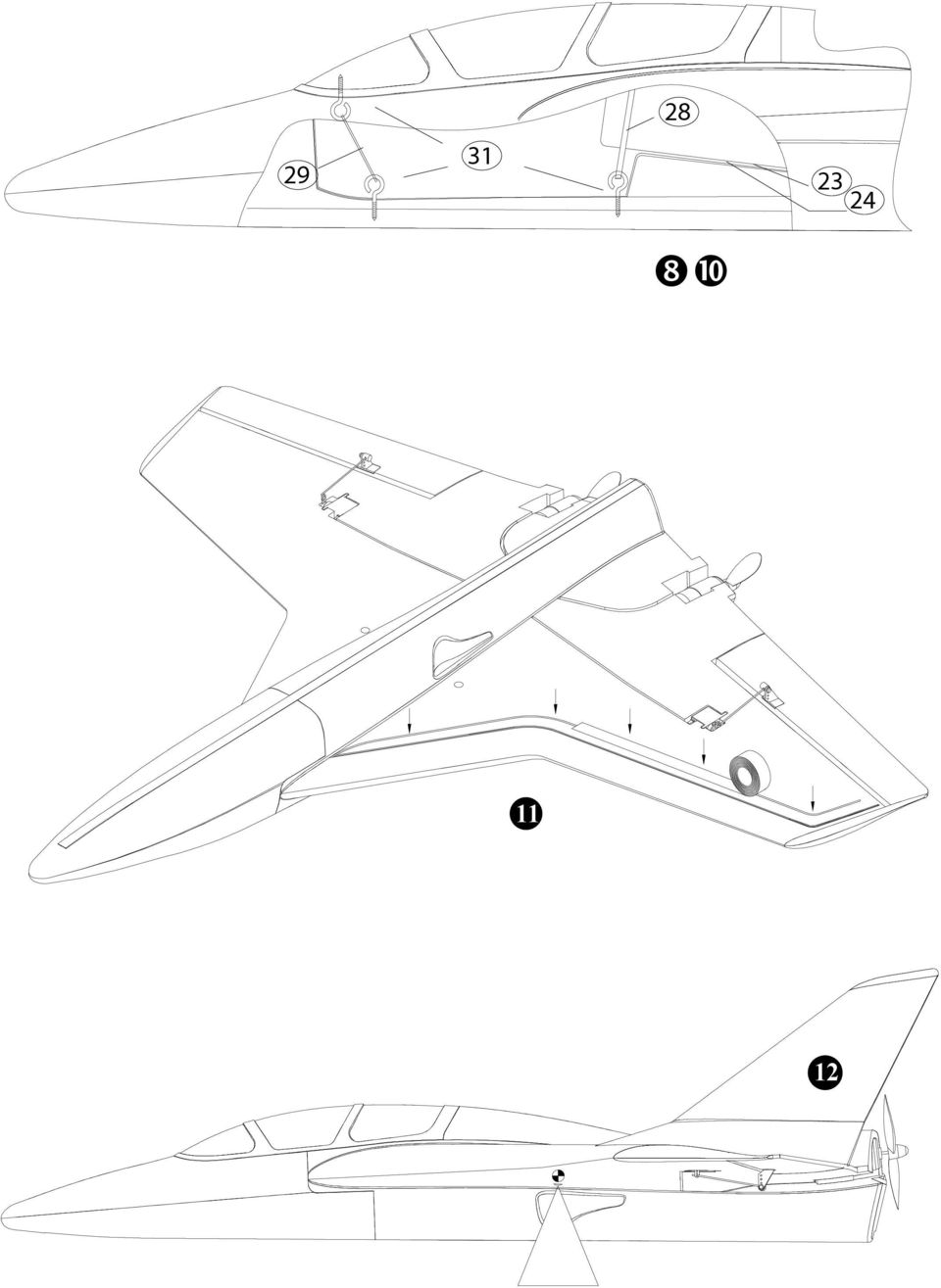
5 den Propeller auf die Motorwelle stecken. Damit sich vor der Motorwelle kein Luftpolster bilden kann, mit einem Bohrer Ø 1-1,5 mm den Spinner nach vorn hin durchbohren. 5. Motor befestigen Die Motoren werden am Motorgehäuse mit einigen Tropfen "Zacki leicht verdickt" in die Motorgondeln geklebt und an der Oberseite (Rundung) ausgerichtet. Eine vollflächige Klebung ist nicht notwendig, sondern nur an den Kanten, so ist es möglich ggf. den Motor bei Defekt zu wechseln. Durch Angabe von Baumwollflocken an den Klebepunkten werden Spalten überbrückt. 6. Kabinenhaube vorbereiten In die rechteckige Aussparung der Kabinenhaube 5 einen 35 mm langen Abschnitt der Leiste 20 mit Zacki einkleben. In die runde Aussparung wird der Hakendübel 22 eingeklebt, in den zuvor ein Schraubhaken 31 eingedreht wurde. Die Haube wird später und beim Fliegen mit dem Gummiring 29 befestigt. 7. Rumpfboden verschließen Alle Kabel im Rumpfbereich einordnen. Auf der Unterseite der Rumpfnase 2 mit einem scharfen Klingenmesser den fertigungsbedingten Steg in der Nut entfernen (A). Die Landekufe (Balsaleiste) 20 ablängen und anpassen. Wer möchte, kann diese Leiste mit Lack imprägnieren oder mit Bügelfolie versiegeln. Die Leiste vor dem Einkleben mit Zacki Aktivator besprühen und ablüften lassen, in die Rumpfnut "Zacki leicht verdickt" angeben - ausreichend aber nicht im Übermaß! Leiste einfügen. 8. Untere Schraubhaken einbringen Im Rumpfboden an der vorderen markierten Stelle und vor der Akkurampe ein Loch von ca. Ø 1,5 mm vorstechen bzw. bohren und die Schraubhaken durch das Tiefziehteil in die Leiste 20 schrauben. Mit Zacki sichern! 9. Seitenruder aufkleben Die Seitenleitwerke 3+4 "trocken" einpassen. Falls die Klebestellen nicht plan auf dem Flügel aufliegen ggf. leicht nacharbeiten, z.b. Grat entfernen. Die Klebstellen mit Zacki Aktivator einsprühen und ablüften lassen. In die Seitenruder- "nester" auf der Tragfläche "Zacki leicht verdickt" angeben und die Ruder einsetzen. Sofort ausrichten und fixieren bis der Klebstoff abgebunden hat. 9. Endmontage An den entsprechenden Positionen wird in den Innenrumpf je ein Streifen Klettband (Hakenseite) 23 geklebt und auf die entsprechenden Einbaukomponenten je einmal die Velourseite des Klettbandes. Die Position der Fernsteuer- und Antriebselemente ist wie folgt vorgesehen: Vorn, hinter dem Gummizug für die Kabinenhaube, der Empfänger..Vor dem Flugakku und dem Schraubhaken für den Akkuhaltegummi, der Regler und der Akku selbst auf der Schräge. Die endgültige Position des Akkus wird beim Auswiegen festgelegt. Mit dem Gummi 28 wird der Akku zusätzlich gesichert. Endmontage - Seitliche Arretierung des Flugakkus Trennen Sie nach Fertigstellung der Landekufe 20 (750mm) und dem Kabinenverschluß 21 (35mm) das überbleibende Reststück der Leiste in zwei etwa gleichlange Teile. Flugakku im Innenrumpf positionieren und die beiden Reststücke ggf. anpassen und rechts und links neben dem Akku am Innenrumpf festkleben Die Empfangsantenne wird durch die durchstoßene Rumpfwand im Tragflächenkanal verstaut und mit Klebeband gesichert 11 Stecken Sie probehalber alle Verbindungen zusammen. Verbindungsstecker für den Motor erst einstecken, wenn Ihr Sender eingeschaltet ist und Sie sicher sind, daß das Bedienelement für die Motorsteuerung auf "AUS" steht. Schalten Sie den Sender ein und verbinden Sie im Modell den Antriebsakku mit dem Regler und den Regler mit dem Empfänger. Es ist notwendig, dass Ihr Regler eine sogenannte BEC-Schaltung besitzt (Empfängerstromversorgung aus dem Flugakku). Nun kurz den Motor einschalten und nochmals die Drehrichtung der Propeller kontrollieren (beim Probelauf Modell festhalten, lose, leichte Gegenstände hinter dem Modell entfernen). Vorsicht, auch bei kleinen Motoren und Luft schrauben besteht Verletzungsgefahr! Wenn alles seinen Platz gefunden hat wird zum Schluß der Rumpfdeckel 6 aufgeklebt. Den Deckel in Verbindung mit der Kabinenhaube "trocken" anpassen, ggf. nacharbeiten. Dann den Deckel mit "Zacki Aktivator einsprühen, ablüften lassen, an die Klebeflächen am Rumpf "Zacki leicht verdickt" angeben und den Deckel positioniert einfügen. 10. Ruderausschläge Um eine ausgewogene Steuerfolgsamkeit zu erzielen, ist die Größe der Ruderausschläge richtig einzustellen: Das Höhenruder nach oben (Knüppel gezogen) ca. 20 mm und nach unten (Knüppel gedrückt) 20 mm. Die Querruderausschläge +/- 15 mm einstellen (keine Differenzierung). Jeweils an der tiefsten Stelle der Ruder gemessen. Falls Ihre Fernsteuerung diese Wege nicht zuläßt, müssen Sie Ihren Gestängeanschluß umsetzen. 11. Auswiegen Um stabile Flugeigenschaften zu erzielen, muss Ihr Twin-Jet, wie jedes andere Flugzeug auch, an einer bestimmten Stelle im Gleichgewicht sein. Montieren Sie Ihr Modell flugfertig und setzen den Antriebsakku ein. Auf der Unter- 5

6 seite der Tragfläche sind Markierungen, in der Nähe der Griffmulden, angebracht. Hier mit den Fingern unterstützt, soll das Modell waagerecht auspendeln. Durch Verschieben des Antriebsakkus sind Korrekturen möglich. Ist die richtige Position gefunden, stellen Sie durch eine Markierung im Akkukasten sicher, dass der Akku immer an derselben Stelle positioniert wird. Der Antriebsakku hat seinen eigenen "Sicherheitsgurt" in Form eines kräftigen Gummizugs. Bitte vor dem Start anlegen, damit nichts "Dummes" passiert. Achten Sie auch darauf, dass die Kabinenhaube sicher schließt (Gummizug). 12 Der Schwerpunkt ist so markiert, dass das Modell bei neutralgestellten Rudern sicher und komfortabel zu steuern ist. Der Start erfolgt mit kräftigem Wurf und etwas nach oben angestellter Rumpfnase (ca10 ), damit das Modell beim "Fahrtholen" genügend Bodenfreiheit zur Verfügung hat. Nach dem Fahrtholen ist das Modell so eingestellt, dass es im Geradeausflug bei Vollgas leicht steigt. Je nach Flugstil kann es vorkommen, dass die Ruder etwas nach unten getrimmt werden - sie sollten jedoch in jedem Fall vor dem nächsten Start auf neutral gestellt werden. 12. Noch etwas für die Schönheit Dazu liegt dem Bausatz ein mehrfarbiger Dekorbogen 16 bei. Die einzelnen Schriftzüge und Embleme werden ausgeschnitten und nach unserer Vorlage oder nach eigenen Vorstellungen aufgebracht. Die Kabine wird mit einem wasserfesten Filzschreiber bis zum Rand geschwärzt. 13. Vorbereitungen für den Erstflug Für den Erstflug warten Sie einen möglichst windstillen Tag ab. Besonders günstig sind oft die Abendstunden. Vor dem ersten Flug unbedingt einen Reichweitentest durchführen! Sender- und Flugakku sind frisch und vorschriftsmäßig geladen. Vor dem Einschalten des Senders sicherstellen, dass der verwendete Kanal frei ist. Ein Helfer entfernt sich mit dem Sender; die Antenne ist dabei ganz eingeschoben. Beim Entfernen eine Steuerfunktion betätigen. Beobachten Sie die Servos. Das nicht gesteuerte soll bis zu einer Entfernung von ca. 80 m ruhig stehen und das gesteuerte muss den Steuerbewegungen verzögerungsfrei folgen. Dieser Test kann nur durchgeführt werden, wenn das Funkband ungestört ist und keine weiteren Fernsteuersender, auch nicht auf anderen Kanälen, in Betrieb sind! Der Test muß mit laufenden Motoren wiederholt werden. Dabei darf sich die Reichweite nur unwesentlich verkürzen. Falls etwas unklar ist, sollte auf keinen Fall ein Start erfolgen. Geben Sie die gesamte Anlage (mit Akku, Schalterkabel, Servos) in die Serviceabteilung des Geräteherstellers zur Überprüfung. Erstflug... Machen Sie keine Startversuche mit stehenden Motoren! Das Modell wird aus der Hand gestartet (immer gegen den Wind). Beim Erstflug lassen Sie sich besser von einem geübten Helfer unterstützen. Nach Erreichen der Sicherheitshöhe, die Ruder über die Trimmschieber am Sender so einstellen, dass das Modell geradeaus fliegt. Machen Sie sich in ausreichender Höhe vertraut, wie das Modell reagiert, wenn die Motoren ausgeschaltet sind. Simulieren Sie Landeanflüge in größerer Höhe, so sind Sie vorbereitet, wenn der Antriebsakku leer wird. Versuchen Sie in der Anfangsphase, insbesondere bei der Landung, keine "Gewaltkurven" dicht über dem Boden. Landen Sie sicher und nehmen besser ein paar Schritte in Kauf, als mit Ihrem Modell bei der Landung einen Bruch zu riskieren. 14. Sicherheit Sicherheit ist oberstes Gebot beim Fliegen mit Flugmodellen. Eine Haftpflichtversicherung ist obligatorisch. Falls Sie in einen Verein oder Verband eintreten, können Sie diese Versicherung dort abschließen. Achten Sie auf ausreichenden Versicherungsschutz (Modellflugzeug mit Antrieb). Halten Sie Modelle und Fernsteuerung immer absolut in Ordnung. Informieren Sie sich über die Ladetechnik für die von Ihnen verwendeten Akkus. Benutzen Sie alle sinnvollen Sicherheitseinrichtungen, die angeboten werden. Informieren Sie sich in unserem Hauptkatalog - MULTIPLEX - Produkte sind von erfahrenen Modellfliegern aus der Praxis für die Praxis gemacht. Fliegen Sie verantwortungsbewusst! Anderen Leuten dicht über die Köpfe zu fliegen ist kein Zeichen für wirkliches Können, der wirkliche Könner hat dies nicht nötig. Weisen Sie auch andere Piloten in unser aller Interesse auf diese Tatsache hin. Fliegen Sie immer so, dass weder Sie noch andere in Gefahr kommen. Denken Sie immer daran, dass auch die allerbeste Fernsteuerung jederzeit durch äußere Einflüsse gestört werden kann. Auch langjährige, unfallfreie Flugpraxis ist keine Garantie für die nächste Flugminute. Wir, das MULTIPLEX - Team, wünschen Ihnen beim Bauen und später beim Fliegen viel Freude und Erfolg. Klaus Michler 6

7 Stückliste Twin-Jet Lfd. Stück Bezeichnung Material Abmessungen 01 1 Tragfläche Partikelschaum Fertigteil 02 1 Rumpfnase Partikelschaum Fertigteil 03 1 Seitenleitwerk links Partikelschaum Fertigteil 04 1 Seitenleitwerk rechts Partikelschaum Fertigteil 05 1 Kabinenhaube Partikelschaum Fertigteil 06 1 Rumpfdeckel Partikelschaum Fertigteil 10 1 Innenrumpf Kunststoff tiefgezogen Fertigteil 15 1 Bauanleitung DIN-A Schriftzug - Dekorsatz bedr. Klebefolie Fertigteil 20 1 Landekufe Balsa 10 x 10 x von Teil 20 abtrennen! Kabinenverschluß Balsa 10 x 10 x 35 mm 22 2 von Teil 20 abtrennen! Seitliche Arretierung Balsa 10 x 10 x ca. 20 mm Zubehörteile 22 1 Hakendübel Holz Ø 10 x 10 mm 23 3 Klettband Hakenseite Kunststoff 25 x 60 mm 24 3 Klettband Velourseite Kunststoff 25 x 60 mm 25 2 U-Scheibe Metall M Inbusschlüssel Metall SW 1, Inbusschraube für Gestängeanschluß MetallM Gummiring Gummi 1x8x Gummiring Gummi 1x1x Rudergestänge m.z. Metall Fertigteil Ø1mm 31 3 Schraubhaken Metall Fertigteil 32 2 Einkleberuderhorn Kunststoff Fertigteil 33 2 Gestängeanschluß Metall Fertigteil 34 2 Mutter Metall M2 Antriebs- u. Kleinteilesatz 35 2 Luftschraube Kunststoff 125 x 110mm 36 2 Antriebsmotor Permax 400 6V Fertigteil 37 1 Anschlußkabel, kpl. mit gr. Stecker Fertigteil 38 2 Kondensator Keramik / Metall 47nF 39 4 Isolierschlauch Kunststoff Fertigteil 10lg. 7

8 TwinJet Building instructions Order No Examine your kit carefully! MULTIPLEX model kits are subject to constant quality checks throughout the production process, and we sincerely hope that you are happy with the contents of your kit. However, we would ask you to check all the parts before you start construction, as we cannot exchange components which you have already worked on. If you find any part is not acceptable for any reason, we will readily correct or exchange it. Just send the component to our Model Department. Please be sure to include a brief description of the fault. We are constantly working on improving our models, and for this reason we must reserve the right to change the kit contents in terms of shape or dimensions of parts, technology, materials and fittings, without prior notification. Please understand that we cannot entertain claims against us if the kit contents do not agree in every respect with the instructions and the illustrations. Caution! Radio-controlled models, and especially model aircraft, are by no means playthings. Building and operating them safely requires a certain level of technical competence and manual skill, together with discipline and a responsible attitude at the flying field. Errors and carelessness in building and flying the model can result in serious personal injury and damage to property. Since we, as manufacturers, have no control over the construction, maintenance and operation of our products, we are obliged to take this opportunity to point out these hazards, and to emphasise your personal responsibility. Additional items required: RC system components: Function MULTIPLEX Micro 5/7 receiver 35 MHz Order No MHz Order No MULTIPLEX MS-X3 servo (2 required) Elevator / aileron Order No PiCO-Control 400 DUO Speed control Order No Flight battery: MULTIPLEX 7/RC2000-2L HS flight battery Order No More power Installing two PERMAX 480 /7.2 V motors, # , provides a significant increase in climb performance and airspeed. If you use 480 motors an 8-cell flight battery is required. Battery charger: PiCO AUTO-charger for rapid-charging transmitter and flight packs Order No Adhesive: MULTIPLEX Medium Zacki Order No MULTIPLEX Zacki Activator Order No PATTEX Kraft contact cement, or similar (not in MPX range) Tools: Scissors, combination pliers, balsa knife, razor saw or hacksaw blade, screwdriver, small round file Specification: Wingspan 910 mm 35,8 inch Fuselage length 802 mm 31,6 inch All-up weight 400 motors / 7 cells approx g 38,8 oz All-up weight 480 motors / 8 cells approx g 42,3 oz Wing area approx dm² 395 sqinch Wing loading min. approx. 43 g/ dm² 13,8 oz/sqinch RC functions Aileron, elevator and motor 8 Separate the illustration pages from the centre of this booklet. Optional national decal set The following decal sheets are available to help you differentiate between examples of the model: black / red / yellow # green / white / red # blue / white / red # red/white/red # UK # USA #

9 Important note This model is not made of styrofoam! It is not possible to glue the material using white glue or epoxy. Please be sure to use the adhesives stated in the instructions. Assembling the model: 1. Attaching the fuselage nose, installing the fuselage liner shell Remove any rough edges from the moulded foam compartments. The first step is to glue the fuselage nose 2 to the main fuselage section 1: check that the parts fit together snugly, then spray one side of the joint surface with ZACKI activator. Allow it to dry for two minutes, then apply Medium Zacki to the other surface, and push the parts together. Cut out the vacuum-moulded liner shell 10 along the mouldedin lines, and cut away the whole of the underside at the rear end to allow the cables to pass through. Temporarily install the liner shell, and fit the canopy 5 and the fuselage top decking 6 to check that it is possible to close the hatches fully; trim the liner shell as required. Glue the liner shell in place using contact cement, using no more adhesive than is necessary. Contact cement attacks the plastic of the liner shell, and too much adhesive may distort and ruin it. Contact cement is usually allowed to air-dry before joining the parts, and this procedure is described in the printed instructions, but for this joint just use it as a conventional glue. Tape the parts together while the contact cement is drying. You may need to pack out the liner shell from the inside to hold it in position. 2. Preparing the wiring The kit includes the power cables 37 used to connect the electric motors 36. Using a small round file or a screwdriver, push a hole through the fuselage sides to extend the cable ducts in the wings, so that the motor and servo cables can be passed through as shown in the drawings. 3. Releasing the elevons, installing the horns For production reasons, and to prevent transit damage, both elevons (control surfaces) are supplied still attached to the wings. Cut through the elevon at the root end using a small fine-bladed metal-cutting saw (for a clean cut). At the tip end you can cut the elevon free using a sharp balsa knife. The decal sheet strip designed to act as the aileron hinge has proved to be less than ideal due to the special characteristics of the ELAPOR foam used for this model. We recommend that you use clear thin adhesive tape (e.g. diamond tape) instead. Prepare the glue-fitting horns 32 for installation in both elevons: fit the pushrod connector 33 in the outermost 2.5 mm Ø hole, and secure it with the washer 25 and nut 34. Spray the horns with Zacki Activator and allow it to dry for a while. Apply Medium Zacki to the horn recesses, and push the horns into place. Allow the glue to set hard. 4. Installing the servos and motors. The model is designed for MULTIPLEX MS-X3 servos. Each servo lead has to be soldered directly to the servo extension lead with separation filter # The extension leads are prepared as follows: Loop the servo extension lead through the ferrite ring eight times; when you have finished, the distance from the ring to the receiver should be 5 to 10 cm. Starting from inside the fuselage, run the cable through the pierced hole in the fuselage side in the direction of the servo well. Make a wire hook, or re-shape a paper clip to help you pull the servo leads through the foam. Solder the wires together, taking care to maintain the colour coding, and insulate each joint with a piece of heat-shrink sleeving. Now temporarily switch on the RC system and centre the sticks and trims, so that you can be sure that the servo output arms are at neutral. Shrink a piece of heat-shrink sleeving round each servo, or wrap the servos in tape. The tape or sleeving prevents glue penetrating into the servo case - and especially into the gears - when the servos are glued in place. Now apply Zacki Activator to the prepared servo, and allow it to dry for a couple of minutes. Apply an adequate quantity (but not too much) of Medium Zacki to the servo well, but only in the area where the tape or sleeve round the servo will make contact. Place the servo in the servo well, then run the cable along the cable duct. If necessary, apply clear tape over the top of the ducts to prevent the wires slipping out. Locate the pre-formed pushrods 30 and connect the Z-bend to the outermost hole in the servo output arm. At the elevon end slide the pushrod through the pushrod connector and secure it with the M3 socket-head grubscrew 27 using the allen key 26; remember to set the elevon to neutral before you tighten the screw. Connecting the motors In the same way, run the motor power leads through the cutaway area of the battery cradle (liner shell) 10 to the motors, starting from inside the fuselage, and route them along the motor cable ducts. Fit the insulating sleeves 39 on the pins of the 47 nf capacitors to guard against short-circuit, then solder the capacitors across the motor terminals. Cut the power cables to length, strip the insulation from the ends and solder them to the motor terminals. As the motors are required to operate in pusher mode, they must be connected with reversed polarity to make them run backwards, i.e. red to black (-), and black to red (+). The Twin-Jet s propellers 35 operate in pusher mode, so for this application they have to be turned round inside the spinner; i.e. the plain (non-inscribed) face of the propeller should face the motor. Fix the propeller to the motor shaft 9

10 with a drop of 5-minute epoxy, or use a little UHU Endfest 300 (slow-setting epoxy) and leave it overnight to cure. On no account use cyano! All you need to do is take a little glue on a pin, apply it to the inside of the hole in the plastic spinner, and then push the propeller onto the motor shaft. Push the pin right through the spinner from the front to prevent an air bubble forming in front of the motor shaft. 5. Installing the electric motors The motors are simply glued in the motor pods by applying a few drops of Medium Zacki to the motor can, and pushing them into place; line up the motors with the edge of the upper rounded side of the pods. It is not necessary to apply glue over a large area of the motor; a few drops at the edges will hold them securely, and they can then easily be cut out if a fault develops. Fill any gaps at the joints with chopped cotton strands. 6. Preparing the canopy Cut a 35 mm long piece from the balsa strip 20, and glue it in the rectangular recess in the canopy 5, using Zacki. Fit a screwhook 31 into the dowel 22, and glue the dowel in the circular hole. When the model is prepared for flying, the canopy is held in place by means of the rubber band Sealing the bottom of the fuselage Arrange all the cables neatly inside the fuselage. The moulding process produces an unwanted projection inside the channel on the underside of the fuselage nose 2. This should be removed using a sharp balsa knife. Cut the landing skid (balsa strip) 20 to length and trim it to fit in the recess in the fuselage. If you wish, you can seal the strip with a coat of paint, or cover it with film. Spray the strip with Zacki Activator before gluing it in place, and let it dry for a while. Apply Medium Zacki to the fuselage channel - enough, but not too much! - and push the strip into place. 8. Fitting the bottom screw-hooks Locate the marked points in the vacuum-moulded liner shell - one at the front, and one forward of the battery ramp - and pierce or drill a hole about 1.5 mm Ø at both points. Fit the screw-hooks through the holes in the liner shell and into the wood strip 20. Apply a drop of Zacki to secure them. 9. Installing the fins Check that the fins are a close fit dry, i.e. without glue. If the joint surfaces do not match the profile of the wing perfectly, remove any rough edges and sand slightly to obtain a good fit. Spray the joint surfaces with Zacki Activator and allow it to dry. Apply Medium Zacki to the fin recesses in the top surface of the wing, and push the fins into place. Check alignment immediately, and tape them in place until the glue has cured. 9. Final assembly Glue strips of Velcro tape (hook side) 23 in the appropriate positions on the inside of the fuselage liner shell, and attach the loop side of the Velcro tape to the corresponding components which are to be held in place. The RC system and power system components should be positioned as follows: At the front, behind the rubber band which retains the canopy, comes the receiver. The speed controller should be installed between the receiver and the second screw-hook, which retains the flight battery. The flight pack itself is fitted on the angled ramp. The battery position can be varied slightly, and its final location is determined when the model is balanced. Extra security is provided for the battery by the rubber band 28. Final assembly - lateral location of the flight pack When you have made the landing skid 20 (750 mm long) and the cabin latch 21 (35 mm), cut the remainder of the strip material into two pieces of roughly equal length. Position the flight pack inside the inner fuselage and trim the two strips to fit on both sides of the battery to provide lateral support. Glue them to the inner fuselage as shown. Run the receiver aerial through the pierced hole in the fuselage side and along the channel in the wing. Secure it with adhesive tape as shown in the drawing. 11 The next step is to test the working systems, and this requires all the electrical connections to be completed. Never connect the motors until you have switched on the transmitter, and have checked carefully that the motor control stick is at OFF. Switch the transmitter on, and connect the flight battery in the model to the speed controller, and the speed controller to the receiver. It is essential that your controller should feature what is known as a BEC circuit (receiver power supply from the flight pack). Switch the motors on briefly from the transmitter, and check the direction of rotation of the propellers (when test-running the motors hold the model really securely, and remove any loose lightweight objects from the area behind the model. Take care: even small motors and propellers represent an injury hazard! Once all the internal components are installed correctly, you can glue the fuselage top decking 6 in place. Trim the decking to fit dry, holding the canopy in place at the same time, and trim the parts if necessary. Spray Zacki Activator on the top decking, let it dry, then apply Medium Zacki to the fuselage joint surfaces, and carefully fit the top decking in position. 10

11 10. Elevon travels The travel of the elevons must be set correctly to achieve a balanced control response. When elevator is applied (forward / back stick), both elevons should rise by about 20 mm when you pull the stick back, and fall by about 20 mm when you move the stick forward. Aileron travel should be +/- 15 mm, i.e. there should be no differential. Measure these travels at the widest point of the elevons. If you cannot achieve these travels with your radio control system, you will need to adjust the mechanical linkages. 11. Balancing The Twin-Jet, like any other aircraft, must be balanced at a particular point in order to achieve stable flying characteristics. Assemble your model, ready to fly, and install the flight battery. You will find moulded-in marks on the underside of the wing roots, close to the hand-grip recesses. Support the model at this point on two fingertips, and it should balance level. If it does not, you can move the flight battery forward or aft to correct the balance point. Once the correct position is found, mark the battery cradle inside the model to ensure that the pack is always replaced in the same position. The drive battery is provided with its own safety belt in the form of a strong rubber band. Please be sure to fit it before each flight, to avoid embarrassing accidents. Be sure to fit the rubber band which holds the canopy in place before you fly the model. 12 The marked CG produces a model which is safe and comfortable to control when the elevons are at neutral. The model should be launched with a powerful throw and the nose angled up at about 10, so that it has sufficient ground clearance when picking up airspeed. Once it is up to speed, the trims should be adjusted so that the model climbs gently at full throttle. Depending on your personal flying style, you may find that you have trimmed the elevons slightly down when you land the model. However, please be sure to reset them to neutral before the next flight. 12. Gilding the lily - applying a little decoration The kit is supplied with a multi-colour decal sheet 16. Cut out the individual name placards and emblems and apply them to the model in the position shown in the kit box illustration, or in an arrangement which you find pleasing. The cabin can be coloured using a waterproof felt-tip pen, continuing the colour down to the edge. 13. Preparing for the first flight For the first flight wait for a day with as little breeze as possible. The early evening is often a good time. Be sure to carry out a range check before the first flight. Just before the flight, charge up the transmitter battery and the flight pack using the correct procedure. Ensure that your channel is not already in use before you switch on the transmitter. Ask your assistant to walk away from the model, holding the transmitter. The aerial should be fitted but completely collapsed. Your assistant should operate one of the functions constantly while you watch the servos. The non-controlled servo should stay motionless up to a range of about 80 m, and the controlled one should follow the stick movements smoothly and without any delay. Please note that this check can only give reliable results if the radio band is clear of interference, and if no other radio control transmitters are in use - even on other channels. If the range check is successful, repeat it with the motors running. There should be only a very slight reduction in effective radio range with the motor turning. If you are not sure about anything, please don t risk a flight. Send the whole system (including battery, switch harness and servos) to the service department of your RC system manufacturer and ask them to check it. The first flight... Don t try an unpowered test-glide with this model! The model is designed for hand-launching, and should always be launched exactly into any wind. If you are a beginner to model flying we strongly recommend that you ask an experienced model pilot to help you for the first few flights. Allow the model to climb to a safe height, then adjust the trim sliders on the transmitter until the model flies in a perfectly straight line hands off. While the model is still at a safe altitude, switch off the motors and try out the model s controls on the glide. Carry out a dry run landing approach at a safe height, so that you are prepared for the real landing when the battery runs flat. Don t try any tight turns at first, and especially not on the landing approach at low altitude. Leave the risky manoeuvres until you are confident of the model s handling. It is always better to land safely at some distance from you, than to force the model back to your feet and risk a heavy landing. 15. Safety Safety is the First Commandment when flying any model aircraft. Third party insurance should be considered a basic essential. If you join a model club suitable cover will usually be available through the organisation. It is your personal responsibility to ensure that your insurance is adequate (i.e. that it covers powered model aircraft). Make it your job to keep your models and your radio control system in perfect order at all times. Check the correct charging procedure for the NC batteries used in your RC set. Make use of all sensible safety systems and precautions which are advised for your system. An excellent source of practical accessories is the MULTIPLEX main catalogue, as our products are designed and manufactured exclusively by practising modellers for other practising modellers. Always fly with a responsible attitude. You may think that flying low over other people s heads is proof of your piloting skill; others know better. The real expert does not need to prove himself in such childish ways. Let other pilots know that this is what you think too. Always fly in such a way that you do not endanger yourself or others. Bear in mind that 11

12 even the best RC system in the world is subject to outside interference. No matter how many years of accident-free flying you have under your belt, you have no idea what will happen in the next minute. We - the MULTIPLEX team - hope you have many hours of pleasure building and flying your new model. Klaus Michler Parts list - Twin-Jet Part No. Description Material Dimensions No. off 01 1 Wing Particle foam Ready made 02 1 Fuselage nose Particle foam Ready made 03 1 Left fin Particle foam Ready made 04 1 Right fin Particle foam Ready made 05 1 Canopy Particle foam Ready made 06 1 Fuselage top decking Particle foam Ready made 10 1 Fuselage liner shell Vac. moulded plastic Ready made 15 1 Building instructions A4 format 16 1 Name placard decal set Printed film Ready made 20 1 Landing skid Balsa 10 x 10 x 800 mm 21 1 Cut from part 20 Canopy hook block Balsa 10 x 10 x 35 mm 22 2 Cut from part 20 lateral location Balsa 10 x 10 x 20 mm Accessories 22 1 Screw-hook dowel Wood 10 Ø x 10 mm 23 3 Velcro tape, hook side Plastic 25 x 60 mm 24 3 Velcro tape, loop side Plastic 25 x 60 mm 25 2 Washer Metal M Allen key Metal 1.5 mm A/F 27 2 Pushrod connector grubscrew Metal M Rubber band Rubber 1 x 8 x Rubber band Rubber 1 x 1 x Pre-formed pushrod Metal Ready made, 1 mm Ø 31 3 Screw-hook Metal Ready made 32 2 Glue-fitting horn Plastic Ready made 33 2 Pushrod connector Metal Ready made 34 2 Nut Metal M2 Power system and small parts 35 2 Propeller Plastic 125 x 110 mm 36 2 Motor Permax 400 6V Ready made 37 1 Power cables, with connectors Ready made 38 2 Capacitor Ceramic / metal 47 nf 39 4 Insulating sleeve Plastic Ready made, 10 long 12

13 TwinJet Notice de montage Réf Familiarisez-vous avec la boîte de construction Les boîtes de construction MULTIPLEX sont soumises à un contrôle qualité permanent, et nous espérons que le contenu de cette boîte est à la hauteur de votre attente. Néanmoins, nous vous conseillons à l aide de la liste ci-jointe, de bien vérifier toutes les pièces avant leur utilisation, car toute pièce travaillée ne pourra ni être reprise, ni échangée. Si une pièce devait être défectueuse, nous nous engageons à la remplacer gratuitement. Dans ce cas, retournez-nous la pièce en question, avec, impérativement, une description succincte du défaut constaté. Nous travaillons constamment à l amélioration de nos modèles. De ce fait, nous nous réservons le droit d apporter toutes modifications de forme, de dimensions, de matière et techniques, sans avis préalable. Nous ne pourrons donc accepter des réclamations quant au contenu de cette notice. Nous vous remercions de votre compréhension. Attention! Des modèles radiocommandés, et plus particulièrement des modèles volants, ne sont pas des jouets. Leur construction et leur utilisation demandent certaines connaissances techniques, un travail soigné ainsi qu un minimum de discipline quant aux règles élémentaires de sécurité. Des erreurs ou des négligences lors de la construction peuvent être la cause d accidents matériels, voire corporels. Ne pouvant intervenir, ni sur la construction, ni sur l entretien et encore moins sur l utilisation du modèle, nous ne pouvons qu attirer votre attention sur ces risques. Accessoires nécessaires: Eléments de la radiocommande: Fonctions Récepteur MULTIPLEX Micro 5/7 35 MHz Réf. Cde MHz Réf. Cde Servos MULTIPLEX MS-X3 (2 servos sont nécessaires) Prof./Ailerons Réf. Cde PiCO Control 400 DUO Variateur Réf. Cde Accu de propulsion: Accu de propulsion MULTIPLEX 7/RC2000-2L H5 Réf. Cde Encore plus de puissance Avec deux moteurs Permax 480, le taux de montée et la vitesse sont encore plus impressionnants. Pour des moteurs de type 480, un accu de propulsion de 8 éléments sera nécessaire. Chargeur: Chargeur PICO-AUTO pour le charge rapide des accus de réception et de propulsion Réf. Cde Colles MULTIPLEX «ZACKI», semi-épaisse Réf. Cde Activateur MULTIPLEX «ZACKI» Réf. Cde Colle KRAFT de PATTEX ou similaire (ne figure pas au programme MPX) Outillage: Ciseaux, pince universelle, cutter ou lame à rasoir, scie fine ou lame de scie à métaux, tournevis et une petite lime ronde. Planche de décoration aux couleurs Caractéristiques techniques: Envergure: 910 mm nationales, en option Pour différencier les modèles en vol, des Long. fuselage: 802 mm planches de décoration de différentes Poids en vol: avec des moteurs de type 400, 7 éléments, env grs couleurs sont désormais disponibles : avec des moteurs de type 480, 8 éléments, env grs Noir / Rouge / Jaune # Surface alaire: env. 25,5 dm² Vert / Blanc / Rouge # Charge alaire: à partir de 43 grs/dm² Bleu / Blanc / Rouge # Fonctions: Ailerons, profondeur, et commande des moteurs. Rouge/Blanc/Rouge # UK # Retirez les vues agrafées au milieu de la notice! USA #

14 Remarque importante Ce modèle n est pas en polystyrène. Les collages avec de la colle blanche ou de l Epoxy ne sont pas possibles. Utilisez les colles recommandées précédemment. Montage du modèle: 1. Collage du nez de l appareil et habillage intérieur du fuselage Retirez si nécessaire, les bavures des pièces moulées. Le nez du fuselage 2 est collé sur le fuselage 1. Ajustez le tout à «sec», puis pulvérisez l activateur ZACKI sur l une des surfaces à coller, laissez évaporer les solvants pendant deux minutes environ, enduisez l autre surface avec de la Zacki légèrement épaissie, puis assemblez les deux pièces. Découpez la pièce moulée 10 selon le marquage. Coupez entièrement la partie inférieure, coté empennage (passage des fils) Montez provisoirement le fuselage intérieur, et vérifiez, avec la verrière 5 et le capot 6 si le capot et la verrière s adapte parfaitement sur le fuselage, si nécessaire, ajustez. Collez le fuselage intérieur avec un peu de colle KRAFT. N en mettez pas trop, sinon le fuselage intérieur se détériore et devient inutilisable. Contrairement à ce qui est indiqué dans le mode d emploi de la colle KRAFT, ne laissez pas évaporer les solvants. Maintenir avec un ruban adhésif jusqu au séchage complet. Vous pouvez éventuellement «bourrer» l intérieur durant le temps de séchage pour bien le plaquer contre les flancs du fuselage. 2.Préparation des câblages Les cordons 37 pour le branchement des moteurs 36 sont fournis. Dans le prolongement du chemin de câbles des cordons dans les ailes, on réalise, pour les cordons de branchement moteurs et servos avec une petite lime ronde ou un tournevis, une ouverture vers le logement du fuselage, et ce, de chaque coté. 3. Mise en place des ailerons et montage des guignols Pour des raisons de transport, les ailerons sont «attachés» sur l aile. Avec une fine lame de scie (trait de scie fin et propre) on rend la mobilité aux ailerons. Aux extrémités des ailerons, on découpe la fente avec une lame à rasoir. Pour couvrir l articulation des ailerons, la solution retenue était de découper une bande adhésive de la planche de décoration. Or il s est avéré, compte tenu des caractéristiques du matériau ELAPOR utilisé, que cette solution n était pas la meilleure. Utilisez une bande charnière transparente classique (p. ex.tesa). Pour les deux ailerons, préparez les guignols à coller 32. Fixez le branchement de la tringle de commande dans le trou Æ 2,5 mm le plus à l extérieur du guignol, et, avec la rondelle U 25, montez l écrou 34. Vaporisez de l activateur Zacki sur les guignols et laissez évaporer les solvants. Mettez de la colle Zacki légèrement épaissie dans les logements des guignols puis collez-les. Laissez sécher! Montage des servos et des moteurs Pour les servos, nous conseillons les servos MULTIPLEX MS- X3. Les fils du servo sont directement soudés sur la rallonge avec l anneau ferrite # Les cordons sont préparés de la manière suivante: Passez 8 fois la rallonge dans l anneau (8 enroulements). La distance entre l anneau-ferrite et le récepteur doit être de 5 10 cm. A travers l ouverture du fuselage, faites passez la rallonge vers le servo. Pour faciliter le passage des fils, utilisez un crochet réalisé facilement avec un bout de corde à piano ou un trombone. Les cordons sont soudés correctement et les soudures isolées avec de la gaine thermorétractable. Faites maintenant fonctionner les servos, pour que les palonniers puissent se mettre en position neutre avant de coller les servos. Mettez de la gaine thermo. autour des servos, ou enveloppezles avec du ruban adhésif. Cette mesure est destinée à empêcher la colle de pénétrer dans le servo, notamment dans la pignonnerie lorsque l on colle le servo. Pulvérisez ensuite de l activateur Zacki sur le servo ainsi «emballé», et laissez évaporer les solvants. Mettez de la colle Zacki légèrement épaissie dans les logements servos, n en mettez pas de trop, (mais uniquement là ou le servo est protégé). Collez maintenant les servos dans leur logement. Montez ensuite les cordons dans leur emplacement en les fixant éventuellement avec du ruban adhésif transparent. Fixez la tringle de commande 30, avec l extrémité en Z dans le trou situé le plus à l extérieur du guignol. Coté gouverne, la tringle est montée dans le raccord 33, maintenu avec la vis 27 six pans creux M3 et serrée avec la clé 26, en faisant cela, veillez à ce que la gouverne soit au neutre. Branchement des moteurs En partant du fuselage, les cordons de branchement des moteurs sont également déposés vers les moteurs, à travers le logement de l accu 10 (fuselage intérieur), dans les chemins de câbles. Sur les pôles de branchement du moteur, soudez le condensateur 38 de 47 nf. Pour éviter tout court-circuit, les pattes du condensateurs sont protégées par la gaine isolante 39. Coupez les cordons à longueur, isolez-les puis soudez-les. Comme les moteurs fonctionnent en propulsif, (rotation à gauche), la polarité doit être inversée, c est à dire le rouge sur le noir (-) et le noir sur le rouge (+). Les hélices 35 du TwinJet travaillent également en propulsion. Il faut, de ce fait, retourner l hélice dans son cône. Le coté non marqué de l hélice doit maintenant être tourné vers le

15

16

17

18
19 moteur. L hélice est collée sur l arbre du moteur avec de la résine à prise rapide ou avec de l UHU Endfest 300 (Ne pas utiliser de colle cyano!). Pour cela, avec une épingle, mettez un peu de colle dans le perçage du cône plastique puis montez l hélice sur l arbre du moteur. Pour éviter q une bulle d air ne se forme à l avant de l arbre lors du montage de l hélice, percez l avant du cône avec une épingle. 5. Fixation des moteurs Les moteurs sont collés avec quelques gouttes de colle Zacki légèrement épaissie dans les nacelles, et positionnés par rapport à l arrondi supérieur. Il n est pas nécessaire d encoller complètement le moteur, ce qui permettra de changer le moteur plus facilement en cas de panne. En mélangeant la colle avec quelques flocons de coton on pourra boucher le jour éventuel entre les deux surfaces. 6. Préparation de la verrière Dans le dégagement rectangulaire de la verrière 5, collez, avec de la colle Zacki un morceau de la baguette 20. Dans le dégagement circulaire, on colle le rondin 22 dans lequel on a vissé auparavant le crochet 31. Par la suite, et en vol, la verrière est fixée par l élastique Fermeture du fond du fuselage Positionnez tous les fils au niveau du fuselage. Sur le dessous du nez du fuselage 2, retirer et le plot ( dû au procédé de fabrication) avec une lame à rasoir. Ajustez et positionnez le patin d atterrissage (baguette Balsa) 20. On peut soit vernir ce patin ou l entoiler, au choix. Avant le collage, pulvérisez de l activateur Zacki sur le patin, laissez évaporer les solvants. Mettez de la Zacki légèrement épaissie dans la rainure du fuselage, n en mettez pas de trop, puis collez le patin. 8. Fixation du crochet inférieur A l endroit marqué du fond du fuselage, percez un trou de Æ 1,5 mm, devant le logement de l accu et vissez le crochet à travers la pièce moulée dans la baguette 20. Freinez avec une goutte de colle Zacki! 9. Fixation de la gouverne de direction Ajustez les dérives 3 et 4 «à sec». Si elles ne reposent pas parfaitement sur l aile, faites les retouches nécessaires, retirez éventuellement les bavures. Pulvérisez de l activateur Zacki sur les surfaces à coller et laissez évaporer les solvants. Mettez un peu de Zacki légèrement épaissie dans les logements des dérives de l aile, montez les dérives, positionnez-les et maintenez-les en place durant tout le temps de séchage. 9. Montage final Aux endroits correspondants, on colle maintenant, dans le fuselage intérieur, un morceau de bande Velcro (coté crocheté) 23, et l autre coté (coté velours) est collé sur les éléments de réception. La positionnement des différents éléments de réception et de propulsion est prévu de manière suivante : A l avant, derrière l élastique qui maintient la verrière, le récepteur ; Devant l accu de propulsion et le crochet de fixation de l élastique qui maintient l accu, le variateur et l accu lui-même, sur chant. La position définitive de l accu sera déterminée lors du centrage. L accu est fixé encore avec l élastique 28. Montage final - calage de l accu de propulsion. Après la réalisation du patin d atterrissage 20 (750mm) et du verrou de verrière 21 (35 mm), coupez la chute qui en résulte en deux morceaux de même longueur. Positionnez l accu de propulsion dans le fuselage intérieur, ajustez si nécessaire ces deux chutes de part et d autre de l accu puis collez-les dans le fuselage. L antenne de la réception est passée au travers du flanc du fuselage, logée dans l aile et fixée avec du ruban adhésif. 11 Branchez provisoirement toutes les prises Ne brancher le moteur que si vous êtes sûr d avoir allumé votre émetteur et que l élément de commande des moteurs est sur «ARRET» Allumez l émetteur, et, dans le modèle, branchez l accu de propulsion au variateur et le variateur au récepteur. Il est nécessaire que que variateur soit équipé du système BEC (alimentation de la réception par l accu de propulsion). Faites tourner brièvement les moteurs pour vérifier leur sens de rotation. Lors de l essai, maintenez fermement le modèle et retirez tous les objets légers qui pourraient se trouver derrière le modèle. Soyez prudents! Même de petits moteurs et de petites hélices peuvent être dangereux! Si tous les éléments on,t trouvés leur place, collez le capot du fuselage 6. Ajustez le capot à la verrière et retouchez si nécessaire. Pulvérisez ensuite le capot avec de l activateur Zacki et laissez évaporer les solvants. Mettez un peu de colle Zacki légèrement épaissie sur les surfaces à encoller du fuselage puis collez le capot en le positionnant correctement. 10. Débattement des gouvernes Pour une bonne maniabilité, il faut régler soigneusement le débattement des gouvernes. Débattement de la gouverne de profondeur : 20 mm vers le haut, et 20 mm vers le bas. Débattement des ailerons (sans différentiel), +/- 15 mm. Ces débattements sont mesurés au bord de fuite de la gouverne. Si votre radio ne permet pas ces débattements, il faudra effectuer ce réglage sur les tringles de commande. 11. Centrage Pour de saines qualités de vol, votre TwinJet, doit être, comme tout autre appareil, centré correctement. 19

20 Montez complètement votre modèle, avec l accu de propulsion. Sur le dessous de l aile il y a deux marquages, au niveau des dégagements qui permettent de lancer le modèle. Si vous soupesez le modèle avec deux doigts à cet endroit là, il doit rester à l horizontale. Des corrections sont possibles en déplaçant l accu.. Si vous avez atteint le centrage correct, marquez la position de l accu dans son logement pour pouvoir le remettre toujours à la même place. L accu a sa propre «ceinture de sécurité», sous forme d un élastique bien costaud! A mettre avant le décollage pour éviter tout incident! 12 Le centrage est réalisé de telle sorte qu en position neutre des gouvernes, le modèle reste maniable et facile à piloter. Le décollage du modèle se fait à la main, avec un lancer énergique, le nez du modèle légèrement relevé vers le haut (env. 10 ), pour qu il ait suffisamment de «garde au sol» pour la prise de vitesse. Le modèle doit être réglé de telle sorte, qu en ligne droite, à pleine vitesse, il monte légèrement. Selon le style de pilotage il se peut que les ailerons devront légèrement être trimés vers le bas. Quoi qu il en soit vous devriez avant chaque décollage remettre les gouvernes au neutre. 12. Un mot encore pour l aspect extérieur Pour cela, une planche de décoration 16 est fournie. Les lettres et les emblèmes sont découpés et posés selon notre exemple ou selon les goûts de chacun. La verrière est noircie jusqu au bord avec un feutre noir indélébile, résistant à l eau. 13. Préparation pour le premier vol Pour le premier vol, essayez de choisir une journée sans vent, de préférence le soir. Il est impératif de faire un essai de portée radio avant le premier vol! Accu d émission et de propulsion correctement chargés selon les instructions. Avant la mise en marche de l émetteur, vérifiez si votre fréquence est libre! Un de vos collègues s éloigne avec votre émetteur, antenne repliée. Lors de l éloignement, il actionne un seul élément de commande. Observez les servos. Jusqu à 80 mètres environ, seul le servo commandé doit réagir correctement, les autres ne doivent pas bouger. Ce test ne peut être réalisé que si votre fréquence n est pas perturbée et que si aucun autre émetteur n est allumé, même sur une autre fréquence que la vôtre. Ce test doit être refait, moteurs en marche. dans ce cas, la réduction de la portée doit être insignifiante. En cas de troubles ou d incertitudes, vous ne devrez en aucun cas décoller. Retournez l ensemble de la radiocommande (avec accus, cordon interrupteur, servos) au Service après vente du constructeur pour une vérification complète. Le premier vol... Ne faites pas des lancers-mains moteurs coupés! Le modèle est lancé à la main, toujours face au vent. Pour le premier vol, il est préférable que vous vous fassiez assister par un pilote chevronné. Après avoir atteint une altitude de sécurité, réglez les trims de telle sorte que votre avion vole droit. Toujours à une altitude suffisante, familiarisez-vous avec les réactions du modèle, lorsque vous coupez les moteurs. Faites des approches à grande altitude, vous serez ainsi préparé lorsque les accus arriveront en fin de charge Dans les premiers temps, lors de l approche finale, évitez les virages serrés à basse altitude. Atterrissez en toute sécurité, il vaut mieux s y reprendre à plusieurs fois, la vie de votre modèle en dépend. 16. Sécurité Le premier souci, lorsque l on fait du modélisme, doit être la sécurité. Une assurance est obligatoire. Si vous êtes membre d un club, vous pouvez y souscrire au sein même de ce club. Vérifiez si elle vous couvre suffisamment (notamment lorsqu il s agit de modèles à propulsion). Prenez soin de votre matériel, et veillez à ce que votre modèle et votre radiocommande soient toujours dans un bon état. Informez-vous sur la manière de charger les accus que vous utilisez. Prenez toutes les précautions utiles qui vous sont données. Notre catalogue pourra également vous informer; tous les produits MULTIPLEX ont été élaborés par des pilotes chevronnés, en partant de faits pratiques pour des utilisations pratiques. Volez prudemment! Passer au ras des personnes n est pas une preuve de savoir faire, un bon pilote n a pas besoin de cela. Dans l intérêt de nous tous, fait le savoir à tous les pilotes. Volez de telle sorte, que ni vous ni le autres soient en danger. N oubliez jamais que la meilleure radiocommande peut être perturbée par des éléments extérieurs ou tomber en panne. Même une longue pratique, sans incidents, n est pas une garantie de sécurité pour la prochaine minute de vol. Toute l équipe MULTIPLEX vous souhaite une construction plaisante et... bon Vol! Multiplex Modelltechnik GmbH Klaus Michler 20

Bedienungsanleitung SUNNYHEAT Standfuß (Art. Nr )
") Bedienungsanleitung SUNNYHEAT Standfuß (Art. Nr. 221012) Der SUNNYHEAT Standfuß ist zur Positionierung Ihres Heizpaneels auf dem Standfuß gedacht. Anwendung findet der Standfuß bei allen Paneelen außer
Bedienungsanleitung SUNNYHEAT Standfuß (Art. Nr. 221012) Der SUNNYHEAT Standfuß ist zur Positionierung Ihres Heizpaneels auf dem Standfuß gedacht. Anwendung findet der Standfuß bei allen Paneelen außer
https://portal.microsoftonline.com
 Sie haben nun Office über Office365 bezogen. Ihr Account wird in Kürze in dem Office365 Portal angelegt. Anschließend können Sie, wie unten beschrieben, die Software beziehen. Congratulations, you have
Montageanleitung Assembly Instruction Artikel: Werkstattschrank mit 2 Türen
 1 Montageanleitung Assembly Instruction Artikel: Werkstattschrank mit 2 Türen Allgemeine Hinweise: Prüfen Sie bitte vor Zusammenbau, ob alle Teile vorhanden und unbeschädigt sind. Sollte das nicht der
Bedienungsanleitung Operation Manual
 Bedienungsanleitung Operation Manual Laminatcutter XP-215 Laminate cutter XP-215 www.cutinator.com 1. Anschlag auf der Ablage Auf der Ablage der Stanze befinden sich drei Arretierungen für den Anschlag.
Snap-in switch for switches PSE, MSM and MCS 30
 Product manual Snap-in switch for switches PSE, MSM and MCS 30 CONTENTS 1. PRODUCT DESCRIPTION 2. DATA AND DIMENSIONAL DRAWINGS 2.1. Technical Data 2.2. Dimensions of PSE with a Mounting Diameter 19 mm
11 EN 81-70 Page 1 of 2 Standard: INTERPRETATION RELATED TO. Clause(s): 5.4.2.3
: 5.4.2.3") CEN RELATED TO 11 Page 1 of 2 Standard: Edition: 2003 Clause(s): 5.4.2.3 Valid from: 15/09/2010 Date of modification: Key-word(s): Car operating panel, Two entrance lift Replacing interpretation No.: QUESTION
CEN RELATED TO 11 Page 1 of 2 Standard: Edition: 2003 Clause(s): 5.4.2.3 Valid from: 15/09/2010 Date of modification: Key-word(s): Car operating panel, Two entrance lift Replacing interpretation No.: QUESTION
CABLE TESTER. Manual DN-14003
 CABLE TESTER Manual DN-14003 Note: Please read and learn safety instructions before use or maintain the equipment This cable tester can t test any electrified product. 9V reduplicated battery is used in
BRUUDT Kennzeichenhalter für die Kawasaki Z800 BRUUDT Tail Tidy fort the Kawasaki Z800
 Montageanleitung Mounting instructions BRUUDT Kennzeichenhalter für die Kawasaki Z800 BRUUDT Tail Tidy fort the Kawasaki Z800 Noch einmal vielen Dank, dass Sie sich für unsere Produkte entschieden haben!
Montageanleitung Assembly Instruction Werkbank mit 6 Schubladen/ 2 Türen
 1 Montageanleitung Assembly Instruction Werkbank mit 6 Schubladen/ 2 Türen Art. 25733 Art. 45700 Allgemeine Hinweise: Prüfen Sie bitte vor Zusammenbau, ob alle Teile vorhanden und unbeschädigt sind. Sollte
miditech 4merge 4-fach MIDI Merger mit :
 miditech 4merge 4-fach MIDI Merger mit : 4 x MIDI Input Port, 4 LEDs für MIDI In Signale 1 x MIDI Output Port MIDI USB Port, auch für USB Power Adapter Power LED und LOGO LEDs Hochwertiges Aluminium Gehäuse
roll-up SONJA powerdisplays Aufbauanleitung Assemble instructions
 powerdisplay SONJA Mit Rollfunktion! Die Werbefläche rollt sich vollständig in das Display. So ist Ihre Werbung geschützt und in Sekunden wieder aufgebaut. Farbe: chrom/silber inkl. Tasche With rolling
KURZANLEITUNG. Firmware-Upgrade: Wie geht das eigentlich?
 KURZANLEITUNG Firmware-Upgrade: Wie geht das eigentlich? Die Firmware ist eine Software, die auf der IP-Kamera installiert ist und alle Funktionen des Gerätes steuert. Nach dem Firmware-Update stehen Ihnen
Radio control model R/CFlugmodell KA-7 SPECIFICATIONS
 Radio control model R/CFlugmodell KA-7 GLIDER VQA058G ARF BY ALL BALSA, PLYWOOD CONSTRUCTION AND ALMOST READY TO FLY Instruction manual / Montageanleitung TECHNISCHE DATEN Spannweite 2540mm Lange 1300mm
BRUUDT Kennzeichenhalter für die Honda NC750X ab 2016 BRUUDT Tail Tidy for the Honda NC750X 2016 and onwards.
 Montageanleitung Mounting instructions BRUUDT Kennzeichenhalter für die Honda NC750X ab 2016 BRUUDT Tail Tidy for the Honda NC750X 2016 and onwards. Noch einmal vielen Dank, dass Sie sich für unsere Produkte
Anleitung F3A Antrieb Adverrun / User manual F3A Drive Adverrun
 Anleitung F3A Antrieb Adverrun / User manual F3A Drive Adverrun Spinner Herzlichen Glückwunsch zum Kauf von Adverrun, ihres neuen leistungsstarken F3A Antriebssystems. Diese Anleitung erläutert die Schritte
Magic Figures. We note that in the example magic square the numbers 1 9 are used. All three rows (columns) have equal sum, called the magic number.
 have equal sum, called the magic number.") Magic Figures Introduction: This lesson builds on ideas from Magic Squares. Students are introduced to a wider collection of Magic Figures and consider constraints on the Magic Number associated with such
Magic Figures Introduction: This lesson builds on ideas from Magic Squares. Students are introduced to a wider collection of Magic Figures and consider constraints on the Magic Number associated with such
Hacker Skyfighter Evo und Skycarver Evo
 Hacker Skyfighter Evo und Skycarver Evo Montage- und Betriebsanleitung / Manual Unsere beiden Erfolgsmodelle wurden nun durch uns überarbeitet. Ein weiterer Grenzschichtzaun, das neue Flügelprofil und
Vor dem Fliegen. Startvorbereitung
 Vor dem Fliegen 1. Fliegen Sie nur an warmen Tagen mit leichten Wind. ~ Der Hubschrauber sollte nie bei Temperaturen über 45 C, bzw unter 0 C geflogen werden. Diese extremen Temperaturen wirken sich auf
Softwareupdate-Anleitung // AC Porty L Netzteileinschub
 1 Softwareupdate-Anleitung // AC Porty L Netzteileinschub Softwareupdate-Anleitung // AC Porty L Netzteileinschub HENSEL-VISIT GmbH & Co. KG Robert-Bunsen-Str. 3 D-97076 Würzburg-Lengfeld GERMANY Tel./Phone:
Installation manual / Montageanleitung WBC2 splice patch with Fibertray Spleissung/Rangierung mit Fibertray
 Content of Assembly Instruction I. Required tools II. Required parts III. Installation Inhalt der Montageanleitung I. Benötigte Werkzeuge II. Benötigte Teile III. Installation I. Required tools: I. Benötigtes
66201 Kleiner Lokschuppen mit micro-motion Torantrieb H0
 66201 Kleiner Lokschuppen mit micro-motion Torantrieb H0 Small Engine Shed with micro-motion Gate Drive H0 Petite remise à locomotives avec commande de porte H0 Pequeño depósito de locomotoras con motor
UWC 8801 / 8802 / 8803
 Wandbedieneinheit Wall Panel UWC 8801 / 8802 / 8803 Bedienungsanleitung User Manual BDA V130601DE UWC 8801 Wandbedieneinheit Anschluss Vor dem Anschluss ist der UMM 8800 unbedingt auszuschalten. Die Übertragung
2 IP X4 WLS/FL IP24. Montage-Anleitung Instructions de montage Assembling instructions. 225 cm. 60 cm 0
 WLS/FL IP Arbeiten an den elektrischen Anlagen dürfen nur von autorisierten Fachleuten nach den örtlichen Vorschriften ausgeführt werden. Für nicht fachgerechte Installation wird jegliche Haftung abgelehnt.
CONTROLLER RECEIVER REPEATER PAIRING SLIM CLIP
 ANLEITUNGEN // INSTRUCTIONS CONTROLLER RECEIVER REPEATER PAIRING SLIM CLIP BEDIENUNGSANLEITUNG // INSTRUCTION MANUAL MONTAGEANLEITUNG // ASSEMBLY INSTRUCTION MONTAGEANLEITUNG // ASSEMBLY INSTRUCTION KOPPLUNG
Titelbild1 ANSYS. Customer Portal LogIn
 Titelbild1 ANSYS Customer Portal LogIn 1 Neuanmeldung Neuanmeldung: Bitte Not yet a member anklicken Adressen-Check Adressdaten eintragen Customer No. ist hier bereits erforderlich HERE - Button Hier nochmal
Aufbaudose mit Schalter Spacing box with switch. Montageanleitung mounting instructions
 Aufbaudose mit Schalter Spacing box with switch Montageanleitung mounting instructions body head Aufbaudose mit Schalter Montageanleitung S. 2 mounting instructions p. 9 $ 0.2m Sicherheitshinweise Die
Uhrenbeweger Watch winders. Crystal
 Uhrenbeweger Watch winders Crystal Sehr geehrter Kunde, unsere Uhrenbeweger sind so konstruiert, dass sie trotz kompakter Abmessungen nur geringe Laufgeräusche verursachen. Jeder Antrieb erzeugt jedoch
rtube.nl/red975 Sold separately MN180008_ Off Price GmbH Rodenkirchener Str Hürth Copyright MICRO-USB RCD2002
 RCD2002 MICRO-USB 1x 1x 1x Sold separately A B QR rtube.nl/red975 1/4 1/8 A W B F = W - 4 cm F = W - 4,5 cm W Min. W = 50 cm Min. W = 50 cm 1 2 W F = W - 4 cm F F 3 4 0,5 cm 5 F - 1,0 cm 2/4 2/8 A B 1
Electrical tests on Bosch unit injectors
 Valid for Bosch unit injectors with order numbers 0 414 700 / 0 414 701 / 0 414 702 Parts Kit Magnet*: - F00H.N37.925 - F00H.N37.933 - F00H.N37.934 * For allocation to the 10-place Bosch order number,
Hazards and measures against hazards by implementation of safe pneumatic circuits
 Application of EN ISO 13849-1 in electro-pneumatic control systems Hazards and measures against hazards by implementation of safe pneumatic circuits These examples of switching circuits are offered free
NiMH accumulators for Robotino. NiMH Akkus für Robotino. Die NiMH-Akkus ersetzen die mit Robotino ausgelieferten Blei-Gel-Akkus.
 NiMH Akkus für Robotino Die NiMH-Akkus ersetzen die mit Robotino ausgelieferten Blei-Gel-Akkus. Das mit Robotino ausgelieferte Ladegerät darf nicht mehr verwendet werden. NiMH accumulators for Robotino
Where are we now? The administration building M 3. Voransicht
 Let me show you around 9 von 26 Where are we now? The administration building M 3 12 von 26 Let me show you around Presenting your company 2 I M 5 Prepositions of place and movement There are many prepositions
hanit Assembly Instruction - Sandbox System Thar -
 Thank you for purchasing a hanit recycling plastic product, We wish you a lot of pleasure with that product. Please find below important installation instructions which need to be taken into consideration
Das mit Robotino ausgelieferte Ladegerät darf nicht mehr verwendet werden.
 NiMH Akkus für Robotino Die NiMH- Akkus ersetzen die mit Robotino ausgelieferten Blei- Gel- Akkus. Das mit Robotino ausgelieferte Ladegerät darf nicht mehr verwendet werden. NiMH accumulators for Robotino
Kurzanleitung um Transponder mit einem scemtec TT Reader und der Software UniDemo zu lesen
 Kurzanleitung um Transponder mit einem scemtec TT Reader und der Software UniDemo zu lesen QuickStart Guide to read a transponder with a scemtec TT reader and software UniDemo Voraussetzung: - PC mit der
Das neue Volume-Flag S (Scannen erforderlich)
") NetWorker 7.4.2 - Allgemein Tip 2, Seite 1/5 Das neue Volume-Flag S (Scannen erforderlich) Nach der Wiederherstellung des Bootstraps ist es sehr wahrscheinlich, daß die in ihm enthaltenen Informationen
NetWorker 7.4.2 - Allgemein Tip 2, Seite 1/5 Das neue Volume-Flag S (Scannen erforderlich) Nach der Wiederherstellung des Bootstraps ist es sehr wahrscheinlich, daß die in ihm enthaltenen Informationen
Englisch-Grundwortschatz
 Englisch-Grundwortschatz Die 100 am häufigsten verwendeten Wörter also auch so so in in even sogar on an / bei / in like wie / mögen their with but first only and time find you get more its those because
Sporadischer Neustart von WPC-Geräten FINALE LÖSUNG
 1 von 8 Sporadischer Neustart von WPC-Geräten FINALE LÖSUNG Leon, der bekannte Experte aus Belgien, hatte bereits vor einiger Zeit einen originellen "quick n dirty" Ansatz zur Lösung des Problems veröffentlicht
Einbauanleitung / Installation Instructions Kit CM44xR
 EA01080C/07/A2/01.13 71225033 Products Solutions Services Einbauanleitung / Installation Instructions Kit CM44xR Externes Display / External display Identifizierung Kit CM44xR 1 Identifizierung 1.1 Lieferumfang
www.okw.com assembly instruction instruction de montage
 www.okw.com assembly instruction instruction de montage MONTAGEANLEITUNG datec-control M/L GEHÄUSE / ENCLOSURE / BOÎTIER Seite / page Best.-Nr./Part-No./Réf. M L DATEC-CONTROL M/L 4 A 90 78 107 A 90 79
Electrical testing of Bosch common rail piezo injectors
 Applies to generation CRI 3: Bosch 10-position order number 0 445 115 = CRI 3-16 (CRI 3.0) 1600 bar 0 445 116 = CRI 3-18 (CRI 3.2) 1800 bar 0 445 117 = CRI 3-20 (CRI 3.3) 2000 bar Tools required: Hybrid
DEU ENG. Bedienungsanleitung Directions for use
 DEU ENG Bedienungsanleitung Directions for use Stand 04/2014 DEU Benutzung im Flugzeug Da dieser Kindersitz in erster Linie zur Verwendung im Auto konstruiert wurde, weicht die Befestigung im Flugzeug
Anleitung. Cheetah 031-4065
 Anleitung Cheetah 031-4065 Vorwort Herzlichen Glückwunsch zum Erwerb des Cheetah. Das Flächenprofil MH-30 in Verbindung mit dem Motor C-3522 mit 900 U/Volt charakterisieren dieses Modell als reinrassigen
Bremszugaustauch für Rollator Nitro
 Bremszugaustausch am Rollator Nitro Es gibt Methoden den Bremszug am Rollator Nitro zu wechseln. Bei der. Methode wird ein mm Inbusschlüssel sowie ein Phillips Kreuzschlitzschraubendreher und Klebe-oder
Listening Comprehension: Talking about language learning
 Talking about language learning Two Swiss teenagers, Ralf and Bettina, are both studying English at a language school in Bristo and are talking about language learning. Remember that Swiss German is quite
CarMedia. Bedienungsanleitung Instruction manual. AC-Services Albert-Schweitzer-Str.4 68766 Hockenheim www.ac-services.eu info@ac-services.
 CarMedia Bedienungsanleitung Instruction manual AC-Services Albert-Schweitzer-Str.4 68766 Hockenheim www.ac-services.eu info@ac-services.eu DE Inhaltsverzeichnis 1. Allgemeine Hinweise... 3 2. CarMedia...
Wandarm inkl. Montagebox und Netzteil Wall bracket incl. installation box and power supply
 Wandarm inkl. Montagebox und Netzteil Wall bracket incl. installation box and power supply Beschreibung und technische Daten: Wandarm (IP-66) mit Montagebox und eingebautem Netzteil Passend für SANTEC
MobiDM-App Handbuch für Windows Mobile
 MobiDM-App Handbuch für Windows Mobile Dieses Handbuch beschreibt die Installation und Nutzung der MobiDM-App für Windows Mobile Version: x.x MobiDM-App Handbuch für Windows Mobile Seite 1 Inhalt 1. WILLKOMMEN
BRUUDT Kennzeichenhalter für die Yamaha MT-03 und R3 BRUUDT Tail Tidy for the Yamaha MT-03 and R3
 Montageanleitung Mounting instructions BRUUDT Kennzeichenhalter für die Yamaha MT-03 und R3 BRUUDT Tail Tidy for the Yamaha MT-03 and R3 Noch einmal vielen Dank, dass Sie sich für unsere Produkte entschieden
Bild 8: Stecken Sie das Fahrwerk in die entsprechende Aussparung an der Unterseite der Tragfläche.
 Deckblatt: Im Bild: Technische Daten/Technical Parameters): Länge: 720mm(28,34 ) Spannweite: 890mm (35,0 ) Fluggewicht: 450g Motor: 370A mit Getriebe Akku: 9,6V 650mAh NI-MH 4-Kanal RC-Anlage(Auch für
Der Adapter Z250I / Z270I lässt sich auf folgenden Betriebssystemen installieren:
 Installationshinweise Z250I / Z270I Adapter IR USB Installation hints Z250I / Z270I Adapter IR USB 06/07 (Laden Sie den Treiber vom WEB, entpacken Sie ihn in ein leeres Verzeichnis und geben Sie dieses
Art : 23P BPI 001 => 16,-
 Universal Brake Pad Wear Indicator for single or double cable systems. kit can be retrofitted at any time to V-Maxx Autosport Big Brake Kit Universal Bremsbelag-Verschleißanzeige für 1 oder 2 Kabel Systeme.
Lockable Tablet Mount
 Gebruikersgids Lockable Tablet Mount resulting resulting in in possible possible equipment equipment damage. damage. create create an an unsecured unsecured installation installation and and may may cause
Anleitung Akku wechseln iphone 5s Manual for battery change on iphone 5s
 Anleitung Akku wechseln iphone 5s Manual for battery change on iphone 5s Bereite Dich auf den Austausch richtig vor! Beginne mit einem Backup, um alle Daten zu sichern. Schalte dann Dein iphone aus und
Montageanleitung / Mounting Instruction
 Montageanleitung / Mounting Instruction FR 771, Differential-Kulissenauszug Bodenmontage, 125 kg Tragkraft, mit Gegenführung FR 771, Progressive-Action Pantry Pullout, Bottom Mount 275 LBS. Capacity, with
DIBELS TM. German Translations of Administration Directions
 DIBELS TM German Translations of Administration Directions Note: These translations can be used with students having limited English proficiency and who would be able to understand the DIBELS tasks better
Word-CRM-Upload-Button. User manual
 Word-CRM-Upload-Button User manual Word-CRM-Upload for MS CRM 2011 Content 1. Preface... 3 2. Installation... 4 2.1. Requirements... 4 2.1.1. Clients... 4 2.2. Installation guidelines... 5 2.2.1. Client...
30 12a. 15b. 12a 25. 15c. 15a. 15b
 AKG Service Department, Lemböckgasse -, A- Wien, Austria.Tel.: (43)4-0, FAX: (43)4-4, e-mail: service@akg.com 0/ 3 4 a 4 4 3 4 a c a 3 / AKG Service Department, Lemböckgasse -, A- Wien, Austria.Tel.: (43)4-0,
Electrical testing of Bosch common rail Injectors
 Electrical testing of Bosch common rail Injectors Contents: 1. Adapter cable for Hybridtester FSA 050 (article number 0 684 010 050 / 1 687 023 571) 2. Electrical testing of Bosch common rail solenoid
p^db=`oj===pìééçêíáåñçêã~íáçå=
 p^db=`oj===pìééçêíáåñçêã~íáçå= Error: "Could not connect to the SQL Server Instance" or "Failed to open a connection to the database." When you attempt to launch ACT! by Sage or ACT by Sage Premium for
User Manual Bedienungsanleitung. www.snom.com. snom Wireless Headset Adapter snom Schnurlos-Headset-Adapter. English. Deutsch
 English snom Wireless Headset Adapter snom Schnurlos-Headset-Adapter Deutsch User Manual Bedienungsanleitung 2007 snom technology AG All rights reserved. Version 1.00 www.snom.com English snom Wireless
FORD 351 CLEVELAND ALTERNATOR & A/C & P/S 30435
 01-30-2018 FORD 351 CLEVELAND ALTERNATOR & A/C & P/S 30435 PARTS LIST Alternator Bracket #3044 1-30444-A...Alternator main bracket 1-30005-A...Alternator re-locator 3-S169...5/16 x 4-1/2 SHCS 1-S248...
Building Instructions. Aufbauanleitung. Service-Hotline:
 86488-2006 02.02.2012 Aufbauanleitung Building Instructions Service-Hotline:+49 421 38693 33 86488-2006 Vergleichen Sie zuerst die Materialliste mit Ihrem Paketinhalt! Bitte haben Sie Verständnis, daß
Parameter-Updatesoftware PF-12 Plus
 Parameter-Updatesoftware PF-12 Plus Mai / May 2015 Inhalt 1. Durchführung des Parameter-Updates... 2 2. Kontakt... 6 Content 1. Performance of the parameter-update... 4 2. Contact... 6 1. Durchführung
Radio control model / Flugmodel GRUNAU BABY GLIDER ARF BY SPECIFICATIONS
 Radio control model / Flugmodel GRUNAU BABY GLIDER ARF BY ALL BALSA, PLYWOOD CONSTRUCTION AND ALMOST READY TO FLY Instruction manual / Montageanleitung TECHNISCHE DATEN Spannweiter 2100mm Lange 1120mm
Honeywell AG Hardhofweg. D-74821 Mosbach MU1H-1220GE23 R1001
 BA 95 Einbau-Anleitung Installation Instructions Einbau Installation Einbaubeispiel Installation example Ablaufleitung vorsehen Install discharge pipework Durchflussrichtung beachten! Consider direction
DOWNLOAD. Englisch in Bewegung. Spiele für den Englischunterricht. Britta Buschmann. Downloadauszug aus dem Originaltitel:
 DOWNLOAD Britta Buschmann Englisch in Bewegung Spiele für den Englischunterricht auszug aus dem Originaltitel: Freeze Hör-/ und Sehverstehen Folgende Bewegungen werden eingeführt: run: auf der Stelle rennen
Einführung in die Robotik Kinematik. Mohamed Oubbati Institut für Neuroinformatik. Tel.: (+49) 731 / 50 24153 mohamed.oubbati@uni-ulm.de 20. 11.
 731 / 50 24153 mohamed.oubbati@uni-ulm.de 20. 11.") Einführung in die Robotik Kinematik Mohamed Oubbati Institut für Neuroinformatik Tel.: (+49) 731 / 50 24153 mohamed.oubbati@uni-ulm.de 20. 11. 2012 Die Klausur findet am 12 März 2013 im H20 um 11h. Dauer:
Einführung in die Robotik Kinematik Mohamed Oubbati Institut für Neuroinformatik Tel.: (+49) 731 / 50 24153 mohamed.oubbati@uni-ulm.de 20. 11. 2012 Die Klausur findet am 12 März 2013 im H20 um 11h. Dauer:
PONS DIE DREI??? FRAGEZEICHEN, ARCTIC ADVENTURE: ENGLISCH LERNEN MIT JUSTUS, PETER UND BOB
 Read Online and Download Ebook PONS DIE DREI??? FRAGEZEICHEN, ARCTIC ADVENTURE: ENGLISCH LERNEN MIT JUSTUS, PETER UND BOB DOWNLOAD EBOOK : PONS DIE DREI??? FRAGEZEICHEN, ARCTIC ADVENTURE: Click link bellow
Montageanleitung der REMUS Klappensteuerung Installation instruction for the REMUS valve control unit
 Nicht für den öffentlichen Straßenverkehr zugelassen! Not approved for usage on public roads! Verpackungsinhalt / Packing contents REMUS Steuereinheit REMUS control module REMUS Funkfernbedienung REMUS
OPERATING INSTRUCTIONS Test pump ZG 5.1. and ZG 5.2.
 Elektromotoren und Gerätebau Barleben GmbH OPERATING INSTRUCTIONS Test pump ZG 5.1. and ZG 5.2. Elektromotoren und Gerätebau Barleben GmbH 2 Inhaltsverzeichnis Page 1 Use 4 2 Design features 4 2.1 Test
66701 micro-motion Liebes-Stadl H0
 66701 micro-motion Liebes-Stadl H0 micro-motion Love Barn H0 micro-motion Grange d amour H0 micro-motion pajar del amor H0 micro-motion liefdesstal H0 3 4 5 1 6 (2x) 2 8 7 11 (2x) 9 (a+b) 10 (2x) 17 18
Cycling and (or?) Trams
 Trams") Cycling and (or?) Trams Can we support both? Experiences from Berne, Switzerland Roland Pfeiffer, Departement for cycling traffic, City of Bern Seite 1 A few words about Bern Seite 2 A few words about
Cycling and (or?) Trams Can we support both? Experiences from Berne, Switzerland Roland Pfeiffer, Departement for cycling traffic, City of Bern Seite 1 A few words about Bern Seite 2 A few words about
CB RADIO Service Manual AE 6890
 CB RADIO Service Manual AE 6890 Downloaded from www.cbradio.nl Technische Mitteilung zu AE 6890 Problem: Bei Montage einer schlecht geerdeten Antenne oder einer Antenne mit schlechtem SWR sehr nahe am
USB Treiber updaten unter Windows 7/Vista
 USB Treiber updaten unter Windows 7/Vista Hinweis: Für den Downloader ist momentan keine 64 Bit Version erhältlich. Der Downloader ist nur kompatibel mit 32 Bit Versionen von Windows 7/Vista. Für den Einsatz
Entwurf. preliminary
 KAPRi plus Erweiterungsset M12 KAPRi plus Extension Kit M12 KAPRi plus Kit d Extension M12 Bedienungsanleitung / User instructions / Instructions d installation 899366 KAPRi plus Erweiterungsset M12 /
 Verwenden Sie nur Original-KRONE-Ersatzteile! Das gibt Sicherheit und spart Kosten! Use Original-KRONE parts only This will increase operational reliability and help to save costs! N'utiliser que des piéces
 Verwenden Sie nur Original-KRONE-Ersatzteile! Das gibt Sicherheit und spart Kosten! Use Original-KRONE parts only This will increase operational reliability and help to save costs! N'utiliser que des piéces
 Verwenden Sie nur Original-KRONE-Ersatzteile! Das gibt Sicherheit und spart Kosten! Use Original-KRONE parts only This will increase operational reliability and help to save costs! N'utiliser que des piéces
Montageanleitung Installation Instructions Notice de Montage
 Montageanleitung Installation Instructions Notice de Montage R Reflexlichtschranke / Reflexlichttaster Retro-reflective sensor / Diffuse reflection sensor Système réflex / Système réflexion directe OE
EEX Kundeninformation 2007-09-05
 EEX Eurex Release 10.0: Dokumentation Windows Server 2003 auf Workstations; Windows Server 2003 Service Pack 2: Information bezüglich Support Sehr geehrte Handelsteilnehmer, Im Rahmen von Eurex Release
PROFIBUS-DP Repeater 1 to 1 and 1 to 5 with optional level converter module
 LSS PROFIBUS-DP Repeater 1 to 1 and 1 to 5 with optional level converter module The LSS PROFIBUS-DP repeaters 1 to 1 and 1 to 5 are used for coupling up to six PROFIBUS bus segments in RS 485 bus technology.
Die Handschrift der Werbung »GUMON!« PIXEL GUM ICON GUM. Straight GUM
 Die Handschrift der Werbung»GUMON!«PIXEL GUM ICON GUM Straight GUM Betont griffig, angenehm berührend, äußerst aktivierend und am besten aus vertrauter Markenhand: So sollte Werbung idealerweise immer
Lithium Fotoakku Ladeset Lithium Photo rechargeable battery Set
 Lithium Fotoakku Ladeset Lithium Photo rechargeable battery Set Technische Daten technical features:: Eingangsspannung: 100-240V AC Input Voltage: 100-240V AC Ausgangsspannung: 3,85V / 7,3V DC Output Voltage:
EINBAUHINWEISE Stilllegungssatz
 EINBAUHINWEISE Stilllegungssatz INSTALLATION INSTRUCTIONS Cancellation kit Seite / Page 1 Vorbereitung Preparation: 1.150 mm der Steuerungsleitung vom Originaldämpfer abtrennen. 1. Cut off 150 mm / 5,9
ODU AMC. Montageanleitung ODU AMC Abreiss-Kabelstecker. Montageanleitung. www.odu.de. Stecker
 ODU AMC Abreiss-Kabelstecker Stecker Schirmhülse Crimphülse 1. Crimphülse und Schirmhülse über das Kabel schieben. Bei Verwen dung eines Metallbandes zur Schirmbefestigung auf der Schirmhülse wird die
Einbauanleitung /Manual Rev. 1
 Knüppelschalter mit 3-pos. / 2-pos. Kippschalter (und Taste) Knüppeltaster (mit zusätzlicher Taste) Für Einbau in Weatronic Sender BAT 60 und BAT 64 Bezugsquelle: RC Technik Peter Herr Müllerweg 34 83071
Montage YAMAHA MT / ABS. Art.-Nr.: schwarz
 Art.-Nr.: 670.4543 schwarz Montage Der Bausatz umfaßt die folgenden Teile: Stück Bestellnr. Bezeichnung 1 700008830 Gepäckplatte 1 700008831 Gepäckplattenunterbau Bitte vor jeder Fahrt den festen Sitz
AKTIVE DVB-T ZIMMERANTENNE ANSCHLUSSHINWEISE ACTIVE DVB-T INDOOR ANTENNA CONNECTION INSTRUCTIONS
 K la vi er l ac ko p tik AKTIVE DVB-T ZIMMERANTENNE ANSCHLUSSHINWEISE ACTIVE DVB-T INDOOR ANTENNA CONNECTION INSTRUCTIONS ZA 8970 DRUCKS0682.indd 1 05.09.12 15:15 VerpAckunGsinhAlT UKW / UHF / VHF Flachantenne
Worx Landroid - Software Update
 Worx Landroid - Software Update WORX Landroid Software Update für Anwender 30.04.2015 Website: www.worxlandroid.com Direct Direkter Link Link for auf the Update: Update: https://www.worxlandroid.com/en/software-update
Ausgleichshalter / Compensation Holder
 usgleichshalter / Compensation Holder usgleichshalter Produkt-Eigenschaften: usgleichshalter für HSK und SK Für Werkzeuge mit Weldon Spanfläche Produkt-Vorteile: Korrektur von Rundlauffehler und chsfehler
Die Bedeutung neurowissenschaftlicher Erkenntnisse für die Werbung (German Edition)
") Die Bedeutung neurowissenschaftlicher Erkenntnisse für die Werbung (German Edition) Lisa Johann Click here if your download doesn"t start automatically Download and Read Free Online Die Bedeutung neurowissenschaftlicher
Die Bedeutung neurowissenschaftlicher Erkenntnisse für die Werbung (German Edition) Lisa Johann Click here if your download doesn"t start automatically Download and Read Free Online Die Bedeutung neurowissenschaftlicher
Wie man heute die Liebe fürs Leben findet
 Wie man heute die Liebe fürs Leben findet Sherrie Schneider Ellen Fein Click here if your download doesn"t start automatically Wie man heute die Liebe fürs Leben findet Sherrie Schneider Ellen Fein Wie
Ref. Nr BMW 328i (F30)
") Ref. Nr. 11 28 0245 BMW 328i (F30) Montageanleitung BMW 328i Motor: N20B20 HARTGE Leistungssteigerung (Basis 180 kw/245 PS) 213 kw (290 PS) bei 5100 U/min 415 Nm bei 2700 U/min Assembly instructions BMW
Ref. Nr. 11 28 0245 BMW 328i (F30) Montageanleitung BMW 328i Motor: N20B20 HARTGE Leistungssteigerung (Basis 180 kw/245 PS) 213 kw (290 PS) bei 5100 U/min 415 Nm bei 2700 U/min Assembly instructions BMW
Motorschutzbügel/ Engine guard
 WICHTIG IMPORTANT Beachten Sie die in Ihrem Land geltenden Zulassungsbestimmungen. Für den Bereich der BRD gilt: Ein Eintrag in die Fahrzeugpapiere ist nicht erforderlich. Die Voraussetzung für die Montage
Electrical testing of Bosch common rail solenoid valve (MV) injectors
 injectors") Applies to MV injector, generation: -CRI 1.0 / 2.0 / 2.1 / 2.2 -CRIN 1 / 2 / 3, with K oder AK plug Bosch 10-position order number Bosch-Bestellnummer CRI: 0 445 110 xxx Bosch-Bestellnummer CRIN: 0 445
Applies to MV injector, generation: -CRI 1.0 / 2.0 / 2.1 / 2.2 -CRIN 1 / 2 / 3, with K oder AK plug Bosch 10-position order number Bosch-Bestellnummer CRI: 0 445 110 xxx Bosch-Bestellnummer CRIN: 0 445
 Bluetooth Headset Modell Nr. BT-ET007 (Version V2.0+EDR) ANLEITUNG Modell Nr. BT-ET007 1. Einführung Das Bluetooth Headset BT-ET007 kann mit jedem Handy verwendet werden, das über eine Bluetooth-Funktion
Gern beraten wir auch Sie. Sprechen Sie uns an!
 de en Unter dem Motto wire Solutions bietet die KIESELSTEIN International GmbH verschiedenste Produkte, Dienstleistungen und After Sales Service rund um den Draht an. Die Verbindung von Tradition und Innovation
GB/DE/AT. Fitting instructions/montageanleitung
 GB/DE/AT Fitting instructions/montageanleitung devicrimp CS-2A Fitting set for twin conductor cables Art. no. 18055350 Reparatur und Verbindungsset für Dünnbettheizmatten mit einem Anschluß Best.-Nr. 18-055422