VICENZA - VERONA. Testata secondo / Tested according to / Geprüft nach / Certifié selon / Probado según : EN12815
|
|
|
- Monika Waldfogel
- vor 7 Jahren
- Abrufe
Transkript

 INDICATED IN THE USER S MANUAL.")
 COMME INDIQUE DANS LA NOTICE D UTILISATION ES PARA EVITAR QUE EL APARATO SE DAÑE, RESPETE EL HORARIO DE LA CARGA DE COMBUSTIBLE INDICADA EN EL MANUAL.")
1 ISTRUZIONI PER L INSTALLAZIONE, L USO E LA MANUTENZIONE - IT INSTRUCTIONS FOR INSTALLATION, USE AND MAINTENANCE - EN ANWEISUNGEN FÜR DIE AUFSTELLUNG, DEN GEBRAUCH UND DIE WARTUNG - DE INSTRUCTIONS POUR L INSTALLATION, L UTILISATION ET L ENTRETIEN FR INSTRUCCIONES PARA LA INSTALACIÓN, EL USO Y EL MANTENIMIENTO - ES VICENZA - VERONA Testata secondo / Tested according to / Geprüft nach / Certifié selon / Probado según : EN12815 IT PER EVITARE DANNI ALL APPARECCHIO, RISPETTARE IL CARICO ORARIO DI COMBUSTIBILE INDICATO NEL PRESENTE LIBRETTO. EN TO AVOID DAMAGES TO THE APPLIANCE, PLEASE RESPECT THE MAX. FUEL QUANTITY (KG/HR) INDICATED IN THE USER S MANUAL. DE UM SCHÄDEN AN DEM GERÄT ZU VERMEIDEN, BITTE BEACHTEN SIE DIE BRENNSTOFFMENGE (KG/H) LT. BEDIENUNGSANLEITUNG. FR POUR EVITER DES DOMMAGES A L APPAREIL RESPECTER LA QUANTITE MAX. DE COMBUSTIBLE (KG/H) COMME INDIQUE DANS LA NOTICE D UTILISATION ES PARA EVITAR QUE EL APARATO SE DAÑE, RESPETE EL HORARIO DE LA CARGA DE COMBUSTIBLE INDICADA EN EL MANUAL. NORME DI SICUREZZA SUGLI APPARECCHI - Per il rispetto delle norme di sicurezza è obbligatorio installare e utilizzare i nostri prodotti seguendo scrupolosamente le indicazioni fornite nel presente manuale. SAFETY REGULATIONS ON THE APPLIANCES- To meet safety regulations, it is compulsory to install and use our products carefully following the instructions contained in this manual. SICHERHEITSVORSCHRIFTEN BEI DEN AUSRÜSTUNGEN - Um die Sicherheitsvorschriften zu beachten, ist es notwendig, unsere Produkte vorsichtig nach den in diesem Handbuch enthaltenen Anweisungen zu installieren und anzuwenden. RÉGLÉS DE SÉCURITÉ SUR LES APPAREILS - Selon les normes de sécurité sur les appareils l acheteur et le commerçant sont contraints de s informer sur le fonctionnement correct sur la base des instructions d emploi. NORMAS DE SEGURIDAD DE LOS APARATOS - Según las normas de seguridad de los aparatos, el comprador y el comerciante tienen la obligación de informarse sobre el correcto funcionamiento según las instrucciones de uso.
2 ITALIANO... 3 ENGLISH DEUTSCH FRANÇAIS ESPAÑOL
3 INFORMAZIONI ALL UTENTE SULLO SMALTIMENTO DELLE APPARECCHIATURE DA PARTE DEI PRIVATI NEL TERRITORIO DELL UNIONE EUROPEA Ai sensi dell art.13 del decreto legislativo 25 luglio 2005, n.151 «attuazione delle direttive 2011/65/CE e 2003/1 08/CE, relative sostanze alla riduzione dell uso di sostanze pericolose nelle apparecchiature elettriche ed elettroniche, nonché allo smaltimento dei rifiuti». il simbolo del cassonetto barrato riportato sull apparecchiatura o sulla confezione indica che il prodotto alla fine della propria vita utile deve essere raccolto separatamente dagli altri rifiuti. L utente dovrà, pertanto, conferire l apparecchiatura giunta a fine vita agli idonei centri di raccolta differenziata dei rifiuti elettronici ed elettrotecnici, oppure riconsegnarla al rivenditore al momento dell acquisto di una nuova apparecchiatura di tipo equivalente, in ragione di uno a uno. L adeguata raccolta differenziata per l awio successivo dell apparecchiatura e dismessa al riciclaggio, al trattamento e allo smaltimento ambientalmente compatibile, contribuisce ad evitare possibili effetti negativi sull ambiente e sulla salute e favorisca il reimpiego e/o riciclo dei materiali di cui è composta l apparecchiatura. Lo smaltimento abusivo del prodotto da parte dell utente comporta l applicazione delle sanzioni amministrative previste dalla normativa vigente, di cui al digs n. 22/1997 (articolo 50 e seguenti del digs n. 22/1997). DICHIARAZIONE DI CONFORMITA DEL COSTRUTTORE Oggetto: Assenza di amianto e cadmio Si dichiara che tutti i nostri apparecchi vengono assemblati con materiali che non presentano parti di amianto o suoi derivati e che nel materiale d apporto utilizzato per le saldature non è presente/utilizzato in nessuna forma il cadmio, come previsto dalla norma di riferimento. Oggetto: Regolamento CE n. 1935/2004 Si dichiara che in tutti gli apparecchi da noi prodotti, i materiali destinati a venire a contatto con i cibi sono adatti all uso alimentari, in conformità al Regolamento CE in oggetto. ITALIANO - INDICE 1. DATI TECNICI AVVERTENZE GENERALI NORME PER L INSTALLAZIONE COLLEGAMENTO ELETTRICO SICUREZZA ANTINCENDIO PRONTO INTERVENTO DESCRIZIONE TECNICA CANNA FUMARIA COMIGNOLO COLLEGAMENTO AL CAMINO COLLEGAMENTO ALLA CANNA FUMARIA DI UN CAMINETTO O FOCOLARE APERTO AFFLUSSO D ARIA NEL LUOGO D INSTALLAZIONE DURANTE LA COMBUSTIONE COMBUSTIBILI AMMESSI / NON AMMESSI ACCENSIONE ACCENSIONE a BASSE EMISSIONI FUNZIONAMENTO NORMALE USO DEL FORNO (dove presente) FUNZIONAMENTO NEI PERIODI DI TRANSIZIONE FERMO ESTIVO MANUTENZIONE E CURA PULIZIA VETRO PULIZIA CASSETTO CENERE PULIZIA CANNA FUMARIA LE MAIOLICHE PRODOTTI IN PIETRA OLLARE PRODOTTI VERNICIATI PRODOTTI SMALTATI COMPONENTI CROMATI COMPONENTI in acciaio INOX CENTRINO E CERCHI in ghisa MANUTENZIONE DEL FORNO (dove presente) PULIZIA VANO RACCOLTA FUMI CUCINE dal forno DETERMINAZIONE DELLA POTENZA TERMICA CAUSE E RIMEDI CONDIZIONI DI GARANZIA DIMENSIONI INSTALLAZIONE Livellamento e allineamento della cucina Sostituzione TOP (40 mm OPTIONAL ) Scarico fumi POSTERIORE Scarico fumi laterale DX-SX Inversione porte
4 1. DATI TECNICI Definizione: secondo Potenza nominale (utile) in kw Assorbimento elettrico in W Rendimento in % Diametro tubo scarico fumi in mm Canna fumaria altezza (m) - dimensioni min (mm) Depressione a rendimento calorifico nominale in Pa (mm H 2 O) Consumo orario legna in Kg/h (legna con 20% umidità max) CO misurato al 13% di ossigeno in % Emissione gas di scarico in g/s - legna Temperatura gas di scarico nel mezzo in C - legna Presa aria esterna Ø in mm (superficie minima cm 2 ) Dimensioni bocca fuoco in mm (L x H) Dimensioni focolare in mm (L x H x P) Dimensioni forno in mm (L x H x P) Tipo di griglia Altezza in mm Larghezza in mm Profondità in mm Peso in Kg Distanze di sicurezza antincendio m 3 riscaldabili (30 Kcal/h x m 3 ) (# #) VICENZA VERONA EN EN , , x 200 Ø x 200 Ø ( 1,1 mm H 2 O) 10 ( 1,0 mm H 2 O) 2,6 2,4 0, mg/m 3 0, mg/m 3 8,6 11, ( 100 cm 2 ) 100 ( 100 cm 2 ) 225 x x x 147 x x 147 x x 175 x x 320 x 430 Griglia piana Capitolo SICUREZZA (# #) Per edifici il cui isolamento termico non corrisponde alle disposizioni sulla protezione del calore, il volume di riscaldamento è: tipo di costruzione favorevole (30 Kcal/h x m 3 ); tipo di costruzione meno favorevole (40 Kcal/h x m 3 ); tipo di costruzione sfavorevole (50 Kcal/h x m 3 ). Con un isolamento termico secondo le norme sul risparmio energetico il volume riscaldato è maggiore. Con un riscaldamento temporaneo, in caso di interruzioni superiori a 8 h, la capacità di riscaldamento diminuisce del 25% circa. 2. AVVERTENZE GENERALI La responsabilità de La NORDICA S.p.A. è limitata alla fornitura dell apparecchio. Il suo impianto va realizzato in modo conforme alla regola dell arte, secondo le prescrizioni delle presenti istruzioni e le regole della professione, da personale qualificato, che agisce a nome di imprese adatte ad assumere l intera responsabilità dell insieme dell impianto. La NORDICA S.p.A. non è responsabile del prodotto modificato senza autorizzazione e tanto meno per l uso di ricambi non originali. Questo apparecchio non è adatto all uso da parte di persone (inclusi bambini) con capacità fisiche, sensoriali e mentali ridotte, o inesperte, a meno che non vengano supervisionate ed istruite nell uso dell apparecchio da una persona responsabile per la loro sicurezza. I bambini devono essere controllati per assicurarsi che non giochino con l apparecchio (EN / 7.12). E OBBLIGATORIO rispettare norme nazionali ed europee, disposizioni locali o in materia edilizia, nonché regolamentazioni antincendio. NON SI POSSONO EFFETTUARE MODIFICHE ALL APPARECCHIO. Non vi sarà responsabilità da parte de La NORDICA S.p.A. in caso di mancato rispetto di tali precauzioni. 3. NORME PER L INSTALLAZIONE L installazione del Prodotto e degli equipaggiamenti ausiliari, relativi all impianto di riscaldamento, deve essere conforme a tutte le Norme e Regolamentazioni attuali ed a quanto previsto dalla Legge. L installazione, i relativi collegamenti dell impianto, la messa in servizio e la verifica del corretto funzionamento devono essere eseguiti a regola d arte da personale professionalmente preparato nel pieno rispetto delle norme vigenti, sia nazionali, regionali, provinciali e comunali presenti nel paese in cui è stato installato l apparecchio, nonché delle presenti istruzioni. L installazione deve essere eseguita da personale autorizzato, che dovrà rilasciare all acquirente una dichiarazione di conformità dell impianto, il quale si assumerà l intera responsabilità dell installazione definitiva e del conseguente buon funzionamento del prodotto installato. Il Prodotto è assemblato e pronto per l allacciamento e deve essere collegata mediante un raccordo all esistente canna fumaria della casa. Il raccordo deve essere possibilmente corto, rettilineo, orizzontale o posizionato leggermente in salita. I collegamenti devono essere a tenuta stagna. Prima dell installazione eseguire le seguenti verifiche:
5 uscita fumi SUPERIORE - POSTERIORE - LATERALE verificare la portata della struttura se regge il peso del vostro apparecchio. In caso di portata insufficiente è necessario adottare opportune misure, la responsabilità de La NORDICA S.p.A. è limitata alla fornitura dell apparecchio (Vedi capitolo DATI TECNICI). Accertarsi che il pavimento possa sostenere il peso dell apparecchio e provvedere ad un adeguato isolamento nel caso sia costruito in materiale infiammabile (DIMENSIONI SECONDO L ORDINAMENTO REGIONALE). Assicurarsi che nella stanza dove sarà installato vi sia una ventilazione adeguata, a tale proposito è fondamentale prestare attenzione a finestre e porte con chiusura stagna (guarnizioni di tenuta). Evitare l installazione in locali con presenza di condotti di ventilazione collettivo, cappe con o senza estrattore, apparecchi a gas di tipo B, pompe di calore o la presenza di apparecchi il cui funzionamento contemporaneo possa mettere in depressione il locale (rif. Norma UNI 10683) Accertarsi che la canna fumaria e i tubi a cui verrà collegato l apparecchio siano idonei, NON è consentito il collegamento di più apparecchi allo stesso camino. Il diametro dell apertura per il collegamento al camino deve corrispondere per lo meno al diametro del tubo fumo. L apertura dovrebbe essere dotata di una connessione a muro per l inserimento del tubo di scarico e di un rosone. Il foro di scarico fumi non utilizzato deve essere chiuso con il relativo tappo (vedi capitolo DIMENSIONI). Tramite i piedini regolabili e mediante l impiego di una livella assicurarsi che l apparecchio sia perfettamente in piano. L installazione deve prevedere l accesso alle operazioni di pulizia e manutenzione del prodotto e della canna fumaria. La NORDICA S.p.A. declina ogni responsabilità per danni a cose e/o persone provocati dall impianto. Inoltre non è responsabile del prodotto modificato senza autorizzazione e tanto meno per l uso di ricambi non originali. Il Vostro abituale spazzacamino di zona deve essere informato sull installazione del prodotto, affinché possa verificarne il regolare collegamento alla canna fumaria ed il grado di efficienza di quest ultima. 4. COLLEGAMENTO ELETTRICO Il prodotto deve essere installato e collegato da personale abilitato secondo le norme vigenti. (Vedi Cap. AVVERTENZE GENERALI). La NORDICA S.p.A. non è responsabile del prodotto modificato senza autorizzazione e tanto meno per l uso di ricambi non originali. ATTENZIONE il cavo di alimentazione NON deve essere a contatto con parti calde. COLLEGAMENTO: Collegare il cavo di alimentazione ad un interruttore bipolare con distanza tra i contatti di almeno 3 mm (Alimentazione 230 V~ 50 Hz, indispensabile il corretto collegamento all impianto di messa a terra). AVVERTENZA: Il PRODOTTO deve essere alimentato in rete con a monte un interruttore generale differenziale di linea come dalle vigenti normative. L uso improprio solleva il costruttore da ogni responsabilità. 5. SICUREZZA ANTINCENDIO Nell installazione del prodotto devono essere osservate le seguenti misure di sicurezza: a) Al fine di assicurare un sufficiente isolamento termico, rispettare la distanza minima di sicurezza dal retro e da entrambi i lati da elementi costruttivi ed oggetti infiammabili e sensibili al calore (mobili, rivestimenti di legno, stoffe ecc.) (vedi Figura 4 a pagina 75 - A). Tutte le distanze minime di sicurezza sono indicate sulla targhetta tecnica del prodotto e NON si deve scendere al di sotto dei valori indicati; b) Davanti alla porta del focolare, nell area di radiazione della stessa non deve esserci alcun oggetto o materiale di costruzione infiammabile e sensibile al calore a meno di 100 cm di distanza. Tale distanza può essere ridotta a 40 cm qualora venga installata una protezione, retroventilata e resistente al calore, davanti all intero componente da proteggere; c) Qualora il prodotto sia installato su un pavimento di materiale infiammabile, bisogna prevedere un sottofondo ignifugo. I pavimenti in materiale infiammabile, come moquette, parquet o sughero etc., devono essere sostituiti da uno strato di materiale non infiammabile, ad esempio ceramica, pietra, vetro o acciaio etc. (dimensioni secondo l ordinamento regionale). Il sottofondo deve sporgere frontalmente di almeno 50 cm e lateralmente di almeno altri 30 cm rispetto l apertura della porta di carico (vedi Figura 4 a pagina 75 - B); d) Sopra al prodotto non devono essere presenti componenti infiammabili (es. mobili - pensili). e) Qualora il prodotto sia installato su una parete di materiale infiammabile, bisogna sostituire la parte di parete interessata dal prodotto, con uno strato di materiale non infiammabile, ad esempio ceramica, pietra, vetro o acciaio etc. La parte di parete sostituita deve sporgere dal prodotto come indicato in Figura 4 a pagina 75 C. Il prodotto deve funzionare esclusivamente con il cassetto cenere inserito. I residui solidi della combustione (ceneri) devono essere raccolti in un contenitore ermetico e resistente al fuoco. Il prodotto non deve mai essere acceso in presenza di emissioni gassose o vapori (per esempio colla per Linoleum, benzina ecc.). Non depositate materiali infiammabili nelle vicinanze del prodotto. Durante la combustione viene sprigionata energia termica che comporta un marcato riscaldamento delle superfici, di porte, maniglie, comandi, vetri, tubo fumi ed eventualmente della parte anteriore dell apparecchio. Evitate il contatto con tali elementi senza un corrispondente abbigliamento protettivo o senza utensili accessori (guanti resistenti al calore, dispositivi di comando). Fate in modo che i bambini siano consapevoli di questi pericoli e teneteli lontani dal focolare durante il suo funzionamento. Quando si utilizza un combustibile errato o troppo umido si formano dei depositi di catrame(creosoto) nella canna fumaria con il rischio d incendio
6 5.1. PRONTO INTERVENTO Se si manifesta un incendio nel collegamento o nella canna fumaria : a) Chiudere la porta di caricamento e del cassetto cenere. b) Chiudere i registri dell aria comburente c) Spegnere tramite l uso di estintori ad anidride carbonica ( CO 2 a polveri ) d) Richiedere l immediato intervento dei Vigili del Fuoco NON SPEGNERE IL FUOCO CON L USO DI GETTI D ACQUA. Quando la canna fumaria smette di bruciare bisogna farla verificare da uno specialista per individuare eventuali crepe o punti permeabili. 6. DESCRIZIONE TECNICA Cucina a legna con possibilità di inserimento tra i mobili. I rivestimenti laterali esterni sono dotati di un sistema di aerazione naturale certificato per cui svolgono una efficace protezione antincendio. Il telaio della cucina è costruito in acciaio INOX. Le aperture per l aerazione sui lati e sulla parte posteriore devono sempre essere mantenute libere per garantire la naturale circolazione dell aria nell apparecchio, altrimenti sussiste il pericolo di surriscaldamento dell apparecchio e dei mobili tra cui è installato. ATTENZIONE pericolo d incendio: non ostruire le aperture per la circolazione naturale dell aria necessaria per evitare il surriscaldamento del prodotto e dei mobili tra cui è installato. Lo stesso dicasi per le aperture dello zoccolo. Le cucine a legna La Nordica si addicono a cucinare sulla piastra e al forno e a riscaldare spazi abitativi per alcuni periodi, o a sostenere un riscaldamento centralizzato insufficiente. Esse sono ideali per appartamenti di vacanza e case del fine settimana oppure come riscaldamento ausiliario durante tutto l anno. Come combustibili vengono utilizzati ceppi di legna. Questo è un apparecchio a combustione intermittente. Il focolare è internamente rivestito di singole lastre in ghisa e NORDIKER, ed è dotato di aria terziaria pretarata per una migliore combustione. Al suo interno si trova una griglia piana di grosso spessore. Il focolare è dotato di una porta panoramica con vetro ceramico interno (resistente fino a 700 C). Questo consente un affascinante vista sulle fiamme ardenti. Inoltre viene così impedita ogni possibile fuoriuscita di scintille e fumo. Sotto la porta del forno si trova un cassetto estraibile porta-legna (VICENZA - PADOVA). Il riscaldamento dell ambiente avviene: per irraggiamento: attraverso il vetro panoramico e le superfici esterne calde della stufa viene irraggiato calore nell ambiente. La cucina a legna è fornita di registri per l aria primaria e secondaria, con i quali viene regolata l aria di combustione. 1A - REGISTRO ARIA PRIMARIA (Figura 6 a pagina 76) Con la manopola posta sulla porta fuoco, si agisce sul regolatore automatico dell aria primaria nella parte bassa della cucina attraverso il cassetto cenere e la griglia in direzione del combustibile. L aria primaria è necessaria per il processo di combustione. Il cassetto cenere deve essere svuotato regolarmente, in modo che la cenere non possa ostacolare l entrata d aria primaria necessaria per la combustione. Attraverso l aria primaria viene anche mantenuto vivo il fuoco. Il registro ha la funzione di aumentare o diminuire automaticamente la combustione. A seconda della posizione scelta, il registro agirà sulla valvola che regola l immissione dell aria nel focolare. Ruotare in senso orario per ravvivare il fuoco e in senso antiorario per ridurre la combustione. Trattandosi di un dispositivo di elevata precisione si raccomanda di ruotare con cura e di non forzare mai la manopola. 2A - IL REGISTRO SECONDARIA (Figura 6 a pagina 76) Sulla porta del focolare si trova il registro dell aria secondaria. Questo registro deve essere aperto (quindi totalmente a Dx) in particolare per la combustione di legna (vedi Tabella). L aria secondaria, passando tra il doppio vetro della porta fuoco, si riscalda ed innesca la doppia combustione aumentando il rendimento e mantenendo nello stesso tempo il vetro pulito ( vedi paragrafo FUNZIONAMENTO). Tramite un tubo flessibile (ignifugo NON fornito) è possibile prelevare l aria SECONDARIA direttamente dall esterno (vedi paragrafo PRESA ARIA ESTERNA). B - REGISTRO-FUMI (Figura 6 a pagina 76) (Conversione dalla funzione di cucina USO ACCENSIONE ((VICENZA - VERONA)) a quella di cucina USO FORNO ) (Conversione dalla funzione di cucina USO PIASTRA ((PADOVA)) a quella di cucina USO FORNO ). Sulla destra del lato anteriore della cucina si trova la leva di comando del registro-fumi. Quando si tira la leva verso di sé, i gas di combustione fluiscono sopra il forno direttamente verso il tronchetto di scarico (funzione cucina - USO ACCENSIONE / PIASTRA); quando invece si spinge la leva verso il retro della cucina, i gas fluiscono intorno al forno aumentando uniformemente la temperatura al suo interno (funzione cucina - USO FORNO ). ATTENZIONE: la valvola di accensione deve restare aperta solo in fase di accensione. Se rimane aperta durante il funzionamento, causa il surriscaldamento del prodotto e danni ai suoi componenti. Inoltre una valvola di accensione aperta determina un maggiore consumo di combustibile. C - Luce FORNO Il forno è dotato di luce, la quale si accende estraendo leggermente la leva C Figura 6 a pagina 76. Per accendere il fuoco seguire quanto segue (vedi capitolo ACCENSIONE) : Portare il registro fumi nella posizione ACCENSIONE / PIASTRA per agevolare lo scarico dei fumi, (aprire anche l eventuale valvola a farfalla posta sul tubo di scarico fumi). Aprire il registro dell aria primaria e secondaria. Dopo aver innescato il fuoco con piccoli pezzi di legna e aspettato che sia ben acceso. Portare il registro fumi nella posizione FORNO. Chiudere l eventuale valvola a farfalla posta sul tubo di scarico fumi
7 Come settare la macchina per la BOLLITURA ACQUA (VERONA) Tenere il registro fumi su funzione cucina USO ACCENSIONE posizione B Figura 6 a pagina 76. Aria Primaria aperta tutta aperta. Aria Secondaria tutta aperta. Fare cariche di legna come da manuale (carica oraria). Come settare la macchina per la COTTURA BISCOTTI (VERONA) Aria Primaria tutta aperta. Aria Secondaria tutta aperta. Portare il registro fumi nella posizione cucina USO ACCENSIONE. Questo mantiene la temperatura del forno stabile attorno ai 230 C. Fare cariche di legna come da manuale (carica oraria) Attendere il raggiungimento dei 230 C senza ulteriori cariche di legna. Inserire la teglia con i biscotti in posizione bassa per minuti (cottura lenta) oppure in posizione media per minuti (cottura veloce). Girare la teglia a metà cottura se necessario. La regolazione dei registri necessaria in fase di accensione è la seguente: 1A - Registro Aria PRIMARIA 2A - Registro Aria SECONDARIA B - REGISTRO-FUMI VICENZA VERONA APERTO APERTO Funzione ACCENSIONE / PIASTRA La regolazione dei registri necessaria per l ottenimento della resa calorifica nominale è la seguente (vedi capitolo DATI TECNICI): 1A - Aria PRIMARIA 2A - Aria SECONDARIA Aria TERZIARIA B - REGISTRO-FUMI VICENZA VERONA APERTO APERTO PRETARATA Funzione FORNO 7. CANNA FUMARIA Requisiti fondamentali per un corretto funzionamento dell apparecchio: la sezione interna deve essere preferibilmente circolare; essere termicamente isolata ed impermeabile e costruita con materiali idonei a resistere al calore, ai prodotti della combustione ed alle eventuali condense; essere priva di strozzature ed avere andamento verticale con deviazioni non superiori a 45 ; se già usata deve essere pulita; rispettare i dati tecnici del manuale di istruzioni; Qualora le canne fumarie fossero a sezione quadrata o rettangolare gli spigoli interni devono essere arrotondati con raggio non inferiore a 20 mm. Per la sezione rettangolare il rapporto massimo tra i lati deve essere 1,5. Una sezione troppo piccola provoca una diminuzione del tiraggio. Si consiglia un altezza minima di 4 m. Sono VIETATE e pertanto pregiudicano il buon funzionamento dell apparecchio: fibrocemento, acciaio zincato, superfici interne ruvide e porose. In Figura 1 a pagina 73 sono riportati alcuni esempi di soluzione. La sezione minima deve essere di 4 dm 2 (per esempio 20x20 cm) per gli apparecchi il cui diametro di condotto è inferiore a 200 mm, o 6,25 dm 2 (per esempio 25x25 cm) per gli apparecchi con diametro superiore a 200 mm. Il tiraggio creato dalla vostra canna fumaria deve essere sufficiente ma non eccessivo. Una sezione della canna fumaria troppo importante può presentare un volume troppo grande da riscaldare e dunque provocare delle difficoltà di funzionamento dell apparecchio; per evitare ciò provvedete ad intubare la stessa per tutta la sua altezza. Una sezione troppo piccola provoca una diminuzione del tiraggio. La canna fumaria deve essere adeguatamente distanziata da materiali infiammabili o combustibili mediante un opportuno isolamento o un intercapedine d aria. E VIETATO far transitare all interno della stessa tubazioni di impianti o canali di adduzione d aria. E proibito inoltre praticare aperture mobili o fisse, sulla stessa, per il collegamento di ulteriori apparecchi diversi (vedi capitolo COLLEGAMENTO ALLA CANNA FUMARIA DI UN CAMINETTO O FOCOLARE APERTO) COMIGNOLO Il tiraggio della canna fumaria dipende anche dall idoneità del comignolo. È pertanto indispensabile che, se costruito artigianalmente, la sezione di uscita sia più di due volte la sezione interna della canna fumaria (Figura 2 a pagina 73). Dovendo sempre superare il colmo del tetto, il comignolo dovrà assicurare lo scarico anche in presenza di vento (Figura 3 a pagina 74). Il comignolo deve rispondere ai seguenti requisiti: Avere sezione interna equivalente a quella del camino. Avere sezione utile d uscita doppia di quella interna della canna fumaria. Essere costruito in modo da impedire la penetrazione nella canna fumaria di pioggia, neve e di qualsiasi corpo estraneo. Essere facilmente ispezionabile, per eventuali operazioni di manutenzione e pulizia COLLEGAMENTO AL CAMINO I prodotti con chiusura automatica della porta devono obbligatoriamente funzionare, per motivi di sicurezza, con la porta del focolare chiusa (fatta eccezione per la fase di carico del combustibile o l eventuale rimozione della cenere). I prodotti con le porte non a chiusura automatica devono essere collegate ad una propria canna fumaria. Il funzionamento con porta aperta è consentito soltanto previa sorveglianza
8 Il tubo di collegamento alla canna fumaria deve essere più corto possibile, rettilineo orizzontale o leggermente in salita, ed a tenuta stagna. Il collegamento deve essere eseguito con tubi stabili e robusti, conforme a tutte le Norme e Regolamentazioni attuali ed a quanto previsto dalla Legge, ed essere fissato ermeticamente alla canna fumaria. Il diametro interno del tubo di collegamento deve corrispondere al diametro esterno del tronchetto di scarico fumi dell apparecchio (DIN 1298). ATTENZIONE: per quanto riguarda la realizzazione del collegamento alla canna fumaria e i materiali infiammabili attenersi a quanto previsto dalla Norma UNI La canna fumaria deve essere adeguatamente distanziata da materiali infiammabili o combustibili mediante un opportuno isolamento o un intercapedine d aria. Distanza minima di sicurezza 25 cm. IMPORTANTE: il foro di scarico fumi non utilizzato deve essere ricoperto con il relativo tappo (vedi Capitolo DIMENSIONI). La depressione al camino (TIRAGGIO) deve essere di almeno 10,11 Pa (=1.0,=1,1 mm di colonna d acqua). La misurazione deve essere fatta sempre ad apparecchio caldo (resa calorifica nominale). Quando la depressione supera i 17 Pascal è necessario ridurla con l installazione di un regolatore di tiraggio supplementare (valvola a farfalla) sul tubo di scarico o nel camino, come da normative vigenti. Per un buon funzionamento dell apparecchio è essenziale che nel luogo d installazione venga immessa sufficiente aria per la combustione (vedi capitolo 8) COLLEGAMENTO ALLA CANNA FUMARIA DI UN CAMINETTO O FOCOLARE APERTO Il canale fumi è il tratto di tubo che collega il Prodotto alla canna fumaria, nel collegamento devono essere rispettati questi semplici ma importantissimi principi: Per nessuna ragione si dovrà usare il canale fumo avente un diametro inferiore a quello del collarino di uscita di cui è dotato il Prodotto; Ogni metro di percorso orizzontale del canale fumo provoca una sensibile perdita di carico che dovrà eventualmente essere compensata con un innalzamento della canna fumaria; Il tratto orizzontale non dovrà comunque mai superare i 2 metri (UNI 10683); Ogni curva del canale fumi riduce sensibilmente il tiraggio della canna fumaria che dovrà essere eventualmente compensata innalzandola adeguatamente; La Normativa UNI ITALIA prevede che le curve o variazioni di direzione non devono in nessun caso essere superiori a 2 compresa l immissione in canna fumaria. Volendo usare la canna fumaria di un caminetto o focolare aperto, sarà necessario chiudere ermeticamente la cappa al di sotto del punto di imbocco del canale fumo pos. A Figura 5 a pagina 75. Se poi la canna fumaria è troppo grande (p.e. cm 30x40 oppure 40x50) è necessario intubarla con un tubo di acciaio Inox di almeno 200mm di diametro, pos. B, avendo cura di chiudere bene lo spazio rimanente fra il tubo e la canna fumaria immediatamente sotto al comignolo pos. C. 8. AFFLUSSO D ARIA NEL LUOGO D INSTALLAZIONE DURANTE LA COMBUSTIONE Poiché questi prodotti ricavano l aria di combustione dal locale di installazione, è OBBLIGATORIO che nel luogo stesso venga immessa una sufficiente quantità d aria. In caso di finestre e porte a tenuta stagna (es. Case costruite con il criterio di risparmio energetico) è possibile che l ingresso di aria fresca non venga più garantito e questo compromette il tiraggio dell apparecchio, il vostro benessere e la vostra sicurezza. Bisogna pertanto garantire una alimentazione aggiuntiva di aria fresca mediante una presa d aria esterna posta nelle vicinanze dell apparecchio oppure tramite la posa di una conduttura per l aria di combustione che porti verso l esterno od in un vicino locale aerato, ad eccezione del locale caldaia o garage (VIETATO). IMPORTANTE. Per un miglior benessere e relativa ossigenazione dell ambiente stesso, l aria può essere prelevata direttamente dall esterno. Per far questo il prodotto può essere collegato alla presa d aria esterna tramite un raccordo (vedi capitolo DIMENSIONI e Figura 10 a pagina 77). Il tubo di collegamento deve essere liscio con un diametro minimo di 100 mm, deve avere una lunghezza massima di 3 m e presentare non più di tre curve. Qualora questo sia collegato direttamente con l esterno deve essere dotato di un apposito frangivento. L entrata dell aria per la combustione nel luogo d installazione non deve essere ostruita durante il funzionamento del Prodotto. E assolutamente necessario che negli ambienti, in cui vengono fatti funzionare prodotti con un tiraggio naturale del camino, venga immessa tanta aria quanta ne è necessaria per la combustione, ossia fino a 20 (<11kW) m³/ora. Il naturale ricircolo dell aria deve essere garantito da alcune aperture fisse verso l esterno, la loro grandezza è stabilita da relative normative in materia. Chiedete informazioni al Vostro spazzacamino di fiducia. Le aperture devono essere protette con delle griglie e non devono mai essere otturate. Una cappa di estrazione (aspirante) installata nella stessa stanza od in una confinante provoca una depressione nell ambiente. Questo provoca la fuori uscita di gas combusti (fumo denso, odore); è dunque necessario assicurare un maggiore afflusso di aria fresca. La depressione di una cappa aspirante può, nella peggiore delle ipotesi, trasformare la canna fumaria del Prodotto in presa d aria esterna risucchiando i fumi nell ambiente con conseguenze gravissime per le persone
9 9. COMBUSTIBILI AMMESSI / NON AMMESSI I combustibili ammessi sono ceppi di legna. Si devono utilizzare esclusivamente ceppi di legna secca (contenuto d acqua max. 20%). Si dovrebbero caricare al massimo 2 o 3 ceppi di legna. I pezzi di legna dovrebbero avere una lunghezza di ca cm ed una circonferenza di massimo cm. I tronchetti di legno pressati non resinati devono essere usati con cautela per evitare surriscaldamenti dannosi all apparecchio, in quanto questi hanno un potere calorifico elevato. La legna usata come combustibile deve avere un contenuto d umidità inferiore al 20% e deve essere deposta in luogo asciutto. La legna umida rende l accensione più difficile, poiché è necessaria una maggiore quantità d energia per far evaporare l acqua presente. Il contenuto umido ha inoltre lo svantaggio che, con l abbassarsi della temperatura, l acqua si condensa prima nel focolare e quindi nel camino causando un notevole deposito di fuliggine con successivo possibile rischio d incendio della stessa. La legna fresca contiene circa il 60% di H 2 O, perciò non è adatta ad essere bruciata. Bisogna collocarla in luogo asciutto e ventilato (per esempio sotto una tettoia) per almeno due anni prima di utilizzarla. Tra gli altri NON possono essere bruciati: carbone, ritagli, cascami di corteccia e pannelli, legna umida o trattata con vernici, materiali di plastica; in tal caso decade la garanzia sull apparecchio. Carta e cartone devono essere utilizzati solo per l accensione. La combustione di rifiuti è VIETATA e danneggerebbe inoltre l apparecchio e la canna fumaria, provocando inoltre danni alla salute ed in virtù del disturbo olfattivo a reclami da parte del vicinato. La legna non è un combustibile a lunga durata e pertanto non è possibile un riscaldamento continuo durante la notte. Specie kg/mc kwh/kg Umidità 20% Faggio 750 4,0 Cerro 900 4,2 Olmo 640 4,1 Pioppo 470 4,1 Larice* 660 4,4 Abete rosso* 450 4,5 Pino silvestre* 550 4,4 * LEGNI RESINOSI POCO ADATTI ATTENZIONE: L uso continuo e prolungato di legna particolarmente ricca di oli aromatici (p.e. Eucalipto, Mirto, etc.) provoca il deterioramento (sfaldamento) repentino dei componenti in ghisa presenti nel prodotto. I dati tecnici dichiarati sono stati ottenuti utilizzando essenza di faggio di classe A1 come da normativa UNI EN ISO e umidità inferiore al 20%. L utilizzo di altre essenze potrebbe comportare la necessità di regolazioni specifiche e potrebbe far ottenere rese diverse dal prodotto
10 10. ACCENSIONE IMPORTANTE: alla prima accensione è inevitabile che venga prodotto un odore sgradevole (dovuto dall essiccamento dei collanti presenti nella cordicella di guarnizione o dalle vernici protettive), il quale sparisce dopo un breve utilizzo. Si deve comunque assicurare una buona ventilazione dell ambiente. Alla prima accensione Vi consigliamo di caricare una quantità ridotta di combustibile e di aumentare lentamente la resa calorifica dell apparecchio. Per una corretta prima accensione dei prodotti trattati con vernici per alte temperature, occorre sapere quanto segue: i materiali di costruzione dei prodotti in questione non sono omogenei, infatti coesistono parti in ghisa e in acciaio. la temperatura alla quale il corpo del prodotto è sottoposto non è omogenea: da zona a zona si registrano temperature variabili dai 300 C ai 500 C; durante la sua vita, il prodotto è sottoposto a cicli alternati di accensioni e di spegnimento durante la stessa giornata e a cicli di intenso utilizzo o di assoluto riposo al variare delle stagioni; prima di potersi definire rodato, il prodotto nuovo dovrà essere sottoposto a diversi cicli di avviamento per poter consentire a tutti i materiali ed alla vernice di completare le varie sollecitazioni elastiche; in particolare inizialmente si potrà notare l emissione di odori tipici dei metalli sottoposti a grande sollecitazione termica e di vernice ancora fresca. Tale vernice, sebbene in fase di costruzione venga cotta a 250 C per qualche ora, dovrà superare più volte e per una certa durata la temperatura di 350 C, prima di incorporarsi perfettamente con le superfici metalliche Diventa quindi importante seguire questi piccoli accorgimenti in fase di accensione: 1. Assicuratevi che sia garantito un forte ricambio d aria nel luogo dove è installato l apparecchio. 2. Nelle prime accensioni, non caricare eccessivamente la camera di combustione (circa metà della quantità indicata nel manuale d istruzioni) e tenere il prodotto acceso per almeno 6-10 ore di continuo, con i registri meno aperti di quanto indicato nel manuale d istruzioni. 3. Ripetere questa operazione per almeno 4-5 o più volte, secondo la Vostra disponibilità. 4. Successivamente caricare sempre più (seguendo comunque quanto descritto sul libretto di istruzione relativamente al massimo carico) e tenere possibilmente lunghi i periodi di accensione evitando, almeno in questa fase iniziale, cicli di accensione-spegnimento di breve durata. 5. Durante le prime accessioni nessun oggetto dovrebbe essere appoggiato sull apparecchio ed in particolare sulle superfici laccate. Le superfici laccate non devono essere toccate durante il riscaldamento. 6. Una volta superato il rodaggio si potrà utilizzare il Vostro prodotto come il motore di un auto, evitando bruschi riscaldamenti con eccessivi carichi. Per accendere il fuoco consigliamo di usare piccoli listelli di legno con carta oppure altri mezzi di accensione in commercio. È VIETATO l uso di tutte le sostanze liquide come per es. alcool, benzina, petrolio e simili. Le aperture per l aria (primaria e secondaria) devono essere aperte contemporaneamente solo un po (si deve aprire anche l eventuale registro di accensione, e valvola a farfalla posta sul tubo di scarico fumi). Quando la legna comincia ad ardere si può ricaricare aprendo lentamente la porta, in modo da evitare fuori uscite di fumo, si chiude il registro dell aria primaria e si controlla la combustione mediante l aria secondaria secondo le indicazioni riportate nel capitolo DESCRIZIONE TECNICA. Durante questa fase, non lasciare mai il focolare senza supervisione. Mai sovraccaricare l apparecchio (consultare la tabella tecnica - quantità max. di combustibile caricabile / consumo orario). Troppo combustibile e troppa aria per la combustione possono causare surriscaldamento e quindi danneggiare l apparecchio. La garanzia non copre i danni dovuti al surriscaldamento dell apparecchio. Non accendere mai l apparecchio quando ci sono gas combustibili nella stanza ACCENSIONE a BASSE EMISSIONI La combustione senza fumo è un metodo di accensione per ridurre in modo significativo le emissioni di sostanze nocive. La legna brucia gradualmente dall alto verso il basso, così la combustione procede più lentamente ed in modo più controllato. I gas combusti, passando attraverso le alte temperature della fiamma, bruciano quasi completamente. Mettere i ciocchi di legna nel focolare ad una certa distanza uno dall altro, come indicato in Figura 7 a pagina 76. Disporre in basso i più grossi e in alto i più fini, o in verticale nel caso di camere di combustione strette e alte. Collocare il modulo di accensione sopra alla catasta, disporre i primi ciocchi del modulo perpendicolarmente alla catasta di legna. Modulo di accensione. Questo modulo di accensione sostituisce quello di carta o cartone. Preparare 4 ciocchi con una sezione trasversale di 3cm x 3cm e una lunghezza di 20 cm Figura 7 a pagina 76. Mettere i quattro ciocchi incrociati sopra la catasta di legna, trasversalmente ad essa, con nel mezzo del modulo l accendi fuoco, che può essere per esempio lana di legna impregnata di cera. Un fiammifero è sufficiente per accendere il fuoco. Volendo si possono utilizzare anche pezzi di legno più sottili: in tal caso ne occorrerà una maggiore quantità. Tenere aperte la valvola di scarico fumi e il registro per l aria comburente. Dopo avere acceso il fuoco, lasciare il registro che regola l aria per la combustione nella posizione indicata : Combustibile Aria PRIMARIA Aria SECONDARIA Aria TERZIARIA Legna CHIUSO 1/2 APERTO PRETARATA IMPORTANTE: non aggiungere ulteriore legna tra una carica completa e l altra; non soffocare il fuoco chiudendo le prese d aria; la pulizia regolare da parte di uno spazzacamino riduce le emissioni di polveri sottili. Queste indicazioni sono sostenute da ENERGIA Legno SVIZZERA
11 11. FUNZIONAMENTO NORMALE Dopo aver posizionato i registri correttamente inserire la carica di legna oraria indicata, evitare sovraccarichi che provocano sollecitazioni anomale e deformazioni (secondo le indicazioni riportate nel capitolo DESCRIZIONE TECNICA). Bisogna sempre usare il prodotto con la porta chiusa per evitare danneggiamenti dovuti all eccessivo surriscaldamento (effetto forgia). La non osservanza di tale regola fa decadere la garanzia. Gli apparecchi con chiusura automatica della porta devono obbligatoriamente funzionare, per motivi di sicurezza, con la porta del focolare chiusa (fatta eccezione per la fase di carico del combustibile o l eventuale rimozione della cenere ). Gli apparecchi con le porte non a chiusura automatica devono essere collegati ad una propria canna fumaria. Il funzionamento con porta aperta è consentito soltanto sotto sorveglianza. IMPORTANTE: Per motivi di sicurezza la porta del focolare può essere aperta solo durante il caricamento di combustibile. Il focolare deve rimanere chiuso durante il funzionamento ed i periodi di non-utilizzo. Con i registri viene regolata l emissione di calore del focolare. Essi devono essere aperti secondo il bisogno calorifico. La migliore combustione (con emissioni minime) viene raggiunta quando, caricando legna, la maggior parte dell aria per la combustione passa attraverso il registro dell aria secondaria. Non si deve mai sovraccaricare l apparecchio. Troppo combustibile e troppa aria per la combustione possono causare surriscaldamento e quindi danneggiare la stufa, in particolare si potrebbero verificare delle rotture sulla parte inferiore della facciata. I danni causati da surriscaldamento non sono coperti da garanzia. Bisogna pertanto usare il prodotto sempre con la porta chiusa per evitare danneggiamenti dovuti all eccessivo surriscaldamento (effetto forgia). La regolazione dei registri necessaria per l ottenimento della resa calorifica nominale con una depressione al camino di 10, 11 Pa (=1,0 =1,1 mm di colonna d acqua) è la seguente: vedi capitolo DESCRIZIONE TECNICA. Questo è un apparecchio a combustione intermittente. Oltre che dalla regolazione dell aria per la combustione, l intensità della combustione e quindi la resa calorifica è influenzata dal camino. Un buon tiraggio del camino richiede una minore quantità d aria per la combustione, mentre uno scarso tiraggio necessita di una maggiore quantità d aria per la combustione. Per verificare la buona combustione, controllate se il fumo che esce dal camino è trasparente. Se è bianco significa che l apparecchio non è regolato correttamente o la legna è troppo bagnata; se invece il fumo è grigio o nero è segno che la combustione non è completa (è necessaria una maggior quantità di aria secondaria). ATTENZIONE: Quando si aggiunge combustibile sopra alle braci in assenza di fiamma si potrebbe verificare un elevato sviluppo di fumi. Se questo dovesse avvenire si potrebbe formare una miscela esplosiva di gas e aria e, in casi estremi verificare un esplosione. Per motivi di sicurezza si consiglia di eseguire una nuova procedura di accensione con utilizzo di piccoli listelli USO DEL FORNO (dove presente) Il forno è dotato di luce, la quale si accende estraendo leggermente la leva C. Per la sostituzione fare riferimento al capitolo MANUTENZIONE DEL FORNO. Posizionare il Registro fumi B Figura 6 a pagina 76 nella posizione USO FORNO (vedi cap. DESCRIZIONE TECNICA). Grazie all apporto d aria per la combustione la temperatura del forno può essere sensibilmente influenzata. Un sufficiente tiraggio al camino e dei canali ben puliti per il flusso dei fumi roventi attorno al forno sono fondamentali per un buon risultato di cottura. La padella forno e la griglia forno possono essere collocate su diversi piani. Torte spesse e arrosti grandi sono da inserire al livello più basso. Torte piatte e biscotti vanno al livello medio. Il livello superiore può essere utilizzato per riscaldare o rosolare (vedi capitolo Descrizione Tecnica - ACCESSORI). Quando si cucinano cibi molto umidi, torte con frutta o frutta stessa si produce acqua di condensa. Durante la cottura può svilupparsi del vapore acqueo che va a depositarsi superiormente o lateralmente sulla porta formando gocce d acqua di condensa. Si tratta di un fenomeno fisico. Aprendo brevemente e con attenzione la porta (1 o 2 volte, più spesso in caso di tempi di cottura più lunghi) si può far uscire il vapore dal vano di cottura e ridurre notevolmente la formazione di condensa FUNZIONAMENTO NEI PERIODI DI TRANSIZIONE Durante il periodo di transizione, ovvero quando le temperature esterne sono più elevate, o in caso di improvviso aumento della temperatura si possono avere dei disturbi alla canna fumaria che fanno si che i gas combusti non vengono aspirati completamente. I gas di scarico non fuoriescono più completamente (odore intenso di gas). In tal caso scuotete più frequentemente la griglia e aumentate l aria per la combustione. Caricate in seguito una quantità ridotta di combustibile facendo sì che questo bruci più rapidamente (con sviluppo di fiamme ) e si stabilizzi così il tiraggio della canna fumaria. Controllate quindi che tutte le aperture per la pulizia e i collegamenti al camino siano ermetici. In caso di incertezza rinunciate all utilizzo dell apparecchio. 12. FERMO ESTIVO Dopo aver effettuato la pulizia del focolare, del camino e della canna fumaria, provvedendo all eliminazione totale della cenere ed altri eventuali residui, è opportuno chiudere tutte le porte con i relativi registri focolare. Nel caso in cui l apparecchio venga disconnesso dal camino, è opportuno chiudere il foro di uscita. E consigliabile effettuare l operazione di pulizia della canna fumaria almeno una volta all anno; verificando nel contempo l effettivo stato delle guarnizioni che se non risultassero perfettamente integre - cioè non più aderenti alla stufa - non garantirebbero il buon funzionamento dell apparecchio! Si renderebbe quindi necessaria la loro sostituzione. In caso di umidità del locale dove è posto l apparecchio, sistemare dei sali assorbenti all interno del focolare. Proteggere le parti in ghisa, se si vuole mantenere inalterato nel tempo l aspetto estetico, con della vaselina neutra
12 13. MANUTENZIONE E CURA Controllare e pulire, almeno una volta all anno, la presa d aria esterna. Il camino deve essere regolarmente ramazzato dallo spazzacamino. Fate controllare dal Vostro spazzacamino responsabile di zona la regolare installazione del prodotto, il collegamento al camino e l aerazione. IMPORTANTE: La manutenzione deve essere eseguita esclusivamente ad apparecchio freddo. Si possono usare esclusivamente parti di ricambio espressamente autorizzate ed offerte da La NORDICA S.p.A. In caso di bisogno Vi preghiamo di rivolgervi al Vs rivenditore specializzato. L APPARECCHIO NON PUÒ ESSERE MODIFICATO! PULIZIA VETRO Tramite uno specifico ingresso dell aria secondaria la formazione di deposito di sporco, sul vetro della porta, viene efficacemente rallentata. Non può comunque mai essere evitata con l utilizzo dei combustibili solidi (es. legna umida ) e questo non è da considerarsi come un difetto dell apparecchio. IMPORTANTE: la pulizia del vetro panoramico deve essere eseguita solo ed esclusivamente a apparecchio freddo per evitarne l esplosione. Per la pulizia si possono usare dei prodotti specifici oppure, con una palla di carta di giornale (quotidiano) inumidita e passata nella cenere. Non usare comunque panni, o prodotti abrasivi o chimicamente aggressivi. La corretta procedura di accensione, l utilizzo di quantità e tipi di combustibili idonei, il corretto posizionamento del registro dell aria secondaria, il sufficiente tiraggio del camino e la presenza dell aria comburente sono indispensabili per il funzionamento ottimale dell apparecchio e per mantenere pulito il vetro. ROTTURA DEI VETRI: i vetri essendo in vetroceramica resistenti fino ad uno sbalzo termico di 750 C, non sono soggetti a shock termici. La loro rottura può essere causata solo da shock meccanici (urti o chiusura violenta della porta ecc.). Pertanto la sostituzione non è in garanzia PULIZIA CASSETTO CENERE Tutti i prodotti hanno una griglia focolare ed un cassetto per la raccolta della ceneri Figura 8 a pagina 76. Vi consigliamo di svuotare periodicamente il cassetto dalla cenere e di evitarne il riempimento totale, per non surriscaldare la griglia. Inoltre Vi consigliamo di lasciare sempre 3-4 cm di cenere nel focolare. ATTENZIONE: le ceneri tolte dal focolare vanno riposte in un recipiente di materiale ignifugo dotato di un coperchio stagno. Il recipiente va posto su di un pavimento ignifugo, lontano da materiali infiammabili fino allo spegnimento e raffreddamento completo delle ceneri PULIZIA CANNA FUMARIA La corretta procedura di accensione, l utilizzo di quantità e tipi di combustibili idonei, il corretto posizionamento del registro dell aria secondaria, il sufficiente tiraggio del camino e la presenza d aria comburente sono indispensabili per il funzionamento ottimale dell apparecchio e per mantenere pulito il vetro. Almeno una volta l anno è consigliabile eseguire una pulizia completa, o qualora sia necessario (problemi di mal funzionamento con scarsa resa). Un eccessivo deposito di fuliggine (creosoto) può provocare problemi nello scarico dei fumi e l incendio della canna fumaria. La pulizia deve essere eseguita esclusivamente ad apparecchio freddo. Questa operazione, dovrebbe essere svolta da uno spazzacamino che contemporaneamente può effettuare un ispezione LE MAIOLICHE Le maioliche La NORDICA S.p.A. sono prodotti di alta fattura artigianale e come tali possono presentare micro-puntinature, cavillature ed imperfezioni cromatiche. Queste caratteristiche ne testimoniano la pregiata natura. Smalto e maiolica, per il loro diverso coefficiente di dilatazione, producono microscrepolature (cavillatura) che ne dimostrano l effettiva autenticità. Per la pulizia delle maioliche si consiglia di usare un panno morbido ed asciutto; se si usa un qualsiasi detergente o liquido, quest ultimo potrebbe penetrare all interno dei cavilli evidenziandoli in modo permanente PRODOTTI IN PIETRA OLLARE La pietra ollare va pulita con della carta abrasiva molto fine o una spugna abrasiva. NON utilizzare alcun detergente o liquido PRODOTTI VERNICIATI Dopo anni di utilizzo del prodotto, la variazione di colore dei particolari verniciati è un fenomeno del tutto normale. Questo fenomeno è dovuto alle notevoli escursioni di temperatura a cui il prodotto è soggetto quando è in funzione e all invecchiamento della vernice stessa con il passare del tempo. AVVERTENZA: prima dell eventuale applicazione della nuova vernice, bisogna pulire e rimuovere ogni residuo dalla superficie da verniciare PRODOTTI SMALTATI Per la pulizia delle parti smaltate usare acqua saponata o detergente Neutro NON abrasivo o chimicamente NON aggressivo, a freddo. Dopo la pulizia NON lasciare asciugare l acqua saponata o il detergente, provvedere alla loro rimozione immediatamente. NON usare carta vetrata o paglietta in ferro COMPONENTI CROMATI Qualora i componenti cromati dovessero diventare azzurrognoli a causa di un surriscaldamento, ciò può essere risolto con un adeguato prodotto per la pulizia
13 13.9. COMPONENTI in acciaio INOX Sempre a prodotto freddo pulire le parti INOX con detersivo neutro NON abrasivo. Per le macchie persistenti usare aceto. Procedere poi ad asciugare tutto con un panno morbido. NON usare carta vetrata o paglietta in ferro. IMPORTANTE: per evitare la formazione di ruggine quando non si utilizza il prodotto per lungo tempo, è consigliabile ingrassare un poco telaio pulito quando è tiepido (con vaselina o olio di paraffina, o olio per macchine da cucire, io olio per armi). Naturalmente, prima del successivo utilizzo il telaio dovrà essere pulito. NON lasciare le pentole o le padelle sul telaio freddo. Ciò causerebbe la presenza di aloni di ruggine, sgradevoli a vedersi e difficili da rimuovere! CENTRINO E CERCHI in ghisa IMPORTANTE: per evitare la formazione di ruggine NON lasciare le pentole o le padelle sulla piastra di cottura fredda. Ciò causerebbe la presenza di aloni di ruggine, sgradevoli a vedersi e difficili da rimuovere! Il centrino in ghisa (cucine) ed i cerchi in ghisa (cucine - stufe) vanno periodicamente carteggiati con carta vetrata grana 150 NON le parti smaltate. - (Cucine) Durante la pulizia bisogna togliere dalla cucina il tronchetto di scarico fumi e il tubo fumi. Il vano di raccolta dei fumi può essere pulito dalla parte frontale del forno (vedi cap. PULIZIA VANO RACCOLTA FUMI CUCINE) oppure dall alto. A tale scopo rimuovere i cerchi e la piastra di cottura e smontare il tubo fumi dal tronchetto di scarico. La pulizia può essere fatta con l aiuto di una spazzola e di un aspiratore. - (Telaio in acciaio INOX) Quando si riposiziona la piastra di cottura in ghisa, accertarsi che tra questa e il telaio in acciaio INOX ci siano sempre 3 mm di spazio per consentire le diverse dilatazioni termiche e per evitare che il telaio in acciaio INOX subisca delle variazioni cromatiche durante il riscaldamento). ATTENZIONE dopo la pulizia tutte le parti smontate devono essere rimontate in modo ermetico MANUTENZIONE DEL FORNO (dove presente) Qualora la lampadina del forno si dovesse rompere, per la sostituzione utilizzare una lampadina con le caratteristiche tecniche indicate in Figura 9 a pagina 76. Dopo avere scollegato il collegamento elettrico procedere con la sostituzione della lampadina dall interno del forno come indicato in Figura 9 a pagina 76. Prima di procedere con il collegamento elettrico: verificare che la tensione elettrica sia la stessa di quella indicata sulla targhetta segnaletica; verificare che la presa di terra sia corretta. Per evitare la possibile formazione di ruggine si raccomanda di: - Fare uscire il vapore dal forno per ridurre la formazione di eventuale condensa aprendo brevemente e con attenzione la porta (1 o 2 volte, più spesso in caso di cottura di cibi molto umidi e tempi di cottura molto lunghi); - Estrarre i cibi dal forno una volta cotti. Lasciare raffreddare i cibi all interno del forno sotto i 150 C comporta la formazione di condensa; - A cottura terminata. Lasciare parzialmente aperta la porta del forno fino a fare asciugare l eventuale condensa; - In caso si fosse formata dell umidità all interno del forno, si consiglia di trattare con della vasellina neutra la parte interna della porta in ghisa. - Ripetere il trattamento di vaselina neutra sulla parte interna della porta in ghisa ogni 3-6 mesi secondo quanto è utilizzato il forno; - In caso si fosse formata della ruggine sulla parte interna della porta in ghisa, rimuovere la ruggine usando del materiale abrasivo dopodiché, trattare la superfice in ghisa con della vasellina neutra. Al fine di assicurare la qualità dei cibi che sono cotti nel forno, l interno delle porte in ghisa NON è stato trattato con alcun prodotto PULIZIA VANO RACCOLTA FUMI CUCINE dal forno Il vano di raccolta dei fumi può essere pulito dal forno ( smontare la lamiera orizzontale che costituisce la base del forno Figura 11 a pagina 78), oppure dall alto. A tale scopo rimuovete i cerchi della piastra di cottura e smontate il tubo-fumi dal tronchetto di scarico. La pulizia può essere effettuata con l aiuto di una spazzola e di un aspiratore. ATTENZIONE dopo la pulizia tutte le parti smontate devono essere rimontate in modo ermetico
14 14. DETERMINAZIONE DELLA POTENZA TERMICA Non esiste regola assoluta che permetta di calcolare la potenza corretta necessaria. Questa potenza è in funzione dello spazio da riscaldare, ma dipende anche in grande misura dall isolamento. In media, la potenza calorifica necessaria per una stanza adeguatamente isolata sarà 30 kcal/h al m 3 (per una temperatura esterna di 0 C). Siccome 1 kw corrisponde a 860 kcal/h, possiamo adottare un valore di 38 W/m 3. Supponendo che desideriate riscaldare una stanza di 150 m 3 (10 x 6 x 2,5 m) in un abitazione isolata, vi occorreranno, 150 m 3 x 38 W/m 3 = 5700 W o 5,7 kw. Come riscaldamento principale un apparecchio di 8 kw sarà dunque sufficiente. Valore indicativo di combustione Quantità richiesta in rapporto a 1 kg di legna secca Carburante Unità kcal/h kw Legna secca (15% di umidità) kg ,00 Legna bagnata (50% di umidità) kg ,95 Bricchette di legna kg ,84 Bricchette di legnite kg ,75 Antracite normale kg ,47 Coke kg ,53 Gas naturale m ,46 Nafta L ,42 Elettricità kw/h , CAUSE E RIMEDI PROBLEMA POSSIBILI CAUSE POSSIBILI SOLUZIONI L intelaiatura della cucina o le parti in acciaio Inox cambiano colore Pressione di mandata (tiraggio) troppo elevata nella canna fumaria Pulire le superfici; Rivolgersi allo spazzacamino per l eventuale montaggio di una valvola a farfalla; Il forno si piega e lo smalto si scheggia Pressione di mandata (tiraggio) troppo elevata nella canna fumaria Piccoli danni allo smalto non compromettono il corretto funzionamento. In caso di scrostamenti più significativi, rivolgersi al Servizio Assistenza; Rivolgersi allo spazzacamino per l eventuale montaggio di una valvola a farfalla; Ruggine sulla piastra di cottura in acciaio Una leggera pattina di ruggine sull intera superficie della piastra di cottura può dipendere dall umidità dell aria (vapore derivante dalla cottura) Smerigliare la superficie; Solo a piastra tiepida, ingrassare la superficie con grasso non acido (vaselina o olio di paraffina); Solo a piastra tiepida, pulire con panno umido ;
15 16. CONDIZIONI DI GARANZIA CONDIZIONI DI GARANZIA 1. I prodotti La Nordica S.p.A. sono garantiti, nell ambito della comunità europea, per un periodo di 24 mesi dalla data di acquisto. L acquisto deve essere provato da un documento fiscalmente valido rilasciato dal rivenditore (scontrino fiscale, fattura o bolla di trasporto) che identifichi il prodotto acquistato e la data di acquisto e/o consegna dello stesso. ATTENZIONE: La presente garanzia convenzionale non sostituisce la garanzia prevista dalle norme europee a tutela dei Consumatori. La garanzia convenzionale si deve intendere limitata al territorio Italiano ed a quei territori all interno della Comunità Europea coperti dal servizio di centri di assistenza tecnica autorizzati (verificare sul sito Deve inoltre intendersi delimitata territorialmente allo stato di residenza e/o domicilio del consumatore che deve essere lo stesso ove ha la sede legale e/o d affari il venditore del prodotto La Nordica S.p.A. Le presenti norme non si applicano nei casi di acquisto del prodotto nell ambito di attività commerciali, imprenditoriali o professionali. In questi casi la garanzia del prodotto sarà limitata ad un periodo di 12 mesi dalla data di acquisto. GARANZIA ITALIA Cosa fare in caso di anomalia nel funzionamento del prodotto: Consultare il libretto di istruzioni per accertarsi che l anomalia non possa essere risolta con la corretta applicazione delle funzionalità del prodotto stesso. Accertarsi che il difetto rientri nella tipologia di anomalie coperte da garanzia; in caso contrario il costo dell intervento sarà a completo carico del consumatore. Quando richiedete l intervento del Servizio Assistenza al Centro di Assistenza Autorizzato indicate sempre: - natura del difetto - modello del vostro apparecchio - indirizzo completo - numero di telefono GARANZIA EUROPA Cosa fare in caso di anomalia nel funzionamento del prodotto: Consultare il libretto di istruzioni per accertarsi che l anomalia non possa essere risolta con la corretta applicazione delle funzionalità del prodotto stesso. Accertarsi che il difetto rientri nella tipologia di anomalie coperte da garanzia; in caso contrario il costo dell intervento sarà a completo carico del consumatore. Richiedete l intervento del Servizio Assistenza o l indirizzo del centro di assistenza tecnica autorizzato al venditore indicando sempre: natura del difetto, modello del vostro apparecchio, indirizzo completo e numero di telefono Per il difetto di conformità manifestatosi nei primi 6 mesi di vita del prodotto il consumatore ha diritto alla riparazione del difetto senza alcuna spesa. Dal settimo al ventiquattresimo mese, nel caso in cui sia stato accertato un vizio di conformità, il consumatore dovrà sostenere il costo della chiamata mentre il venditore continuerà a farsi carico del costo della manodopera e di eventuali ricambi funzionali utilizzati. 2. Qualora il difetto riscontrato sia riconducibile a condizioni e/o eventi esterni quali, a puro titolo esemplificativo e non esaustivo, portata insufficiente degli impianti; errata installazione e/o manutenzione operata da personale non in possesso dei requisiti previsti dalle leggi in vigore nel paese di residenza del consumatore; negligenza; incapacità d uso e cattiva manutenzione da parte del consumatore, rispetto a quanto riportato e raccomandato nel libretto di istruzioni del prodotto, che costituisce parte integrante del contratto di vendita, decade la presente garanzia. Non sono altresì compresi nella presente garanzia i danni subiti dal prodotto in assenza di cause provate imputabili a vizi di fabbricazione. Allo stesso modo sono esclusi dalla presente garanzia i vizi riconducibili al mancato corretto funzionamento della canna fumaria, ai sensi della legislazione in vigore nel paese al momento dell acquisto, così come tutti i difetti del prodotto dovuti ad incuria, rottura accidentale, manomissione e/o danneggiamento nel trasporto (graffi, ammaccature etc.), interventi eseguiti da personale non autorizzato ed ulteriori danni causati da erronei interventi del consumatore nel tentativo di porre rimedio all iniziale guasto. Sono esclusi da garanzia i seguenti materiali di consumo: le guarnizioni, i vetri ceramici o temperati, i rivestimenti e griglie in ghisa, materiali refrattari ( es. Nordiker o altro), i particolari verniciati, cromati o dorati, gli elementi in maiolica, le maniglie, il braciere ed i relativi componenti. Nei prodotti Idro lo scambiatore di calore è escluso dalla garanzia nel caso in cui non venga realizzato un adeguato circuito anticondensa che garantisca una temperatura di ritorno dell apparecchio di almeno 55 gradi. In generale sono esclusi da garanzia tutti i componenti esterni al prodotto sui quali il consumatore può intervenire direttamente durante l uso e/o manutenzione o che possono essere soggetti ad usura, e/o la formazione di ruggine, macchie su acciaio dovute all utilizzo di detergenti aggressivi. In caso di segnalazione di difetti non riscontrati poi in fase di verifica da parte di un tecnico autorizzato, l intervento sarà a completo carico del consumatore. 3. Qualora il ripristino alla conformità non fosse possibile attraverso la riparazione del prodotto/componente, si provvederà alla sostituzione, lasciando immutati la scadenza ed i termini di garanzia acquisiti al momento dell acquisto del prodotto/componente da sostituire. 4. La Nordica S.p.A. declina ogni responsabilità per eventuali danni che possono, direttamente o indirettamente, derivare a persone, animali e cose, in conseguenza alla mancata osservanza di tutte le prescrizioni indicate nell apposito libretto istruzioni e concernenti le avvertenze in tema di installazione, uso e manutenzione del prodotto, scaricabile anche dal sito internet. 5. Sono esclusi dalla garanzia gli interventi per la taratura e/o regolazione del prodotto in relazione al tipo di combustibile o altro
16 6. Qualora il Prodotto venisse riparato presso uno dei Centri Assistenza Tecnica Autorizzati indicati dalla La Nordica S.p.A. e nel caso di sostituzione del prodotto, il trasporto sarà gratuito. Nei casi in cui il tecnico fosse in grado di riparare il prodotto presso il domicilio dell utente, è lo stesso si rifiutasse, il trasporto in laboratorio e la riconsegna saranno invece a suo carico. 7. Trascorso il periodo di 24 mesi di garanzia ogni intervento di riparazione sarà a completo carico del consumatore. 8. In caso di controversie il foro giudiziario esclusivamente competente è il foro della sede legale di La Nordica S.p.A. - (Vicenza-Italia) ULTERIORI AVVERTENZE Utilizzare esclusivamente il combustibile raccomandato dal produttore. Il prodotto non deve essere utilizzato come inceneritore. Non utilizzare il prodotto come scala o struttura di appoggio. Non mettere ad asciugare biancheria sul prodotto. Eventuali stendibiancheria o simili devono essere tenuti ad apposita distanza dal prodotto. Pericolo di incendio e danneggiamento del rivestimento. Ogni responsabilità per un uso improprio del prodotto è totalmente a carico dell utente e solleva il produttore da ogni responsabilità civile e penale. Qualsiasi tipo di manomissione o di sostituzione non autorizzata di particolari non originali del prodotto può essere pericoloso per l incolumità dell operatore e sollevano la ditta da ogni responsabilità civile e penale. Gran parte delle superfici del prodotto sono molto calde (porta, maniglia, vetro, tubi uscita fumi, ecc.). Occorre quindi evitare di entrare in contatto con queste parti senza adeguati indumenti di protezione o appositi mezzi, come ad esempio guanti a protezione termica E vietato far funzionare il prodotto con la porta aperta o con il vetro rotto. Il prodotto deve essere connesso elettricamente ad un impianto munito di un efficace sistema di messa a terra. Spegnere il prodotto in caso di guasto o cattivo funzionamento. Non lavare il prodotto con acqua. L acqua potrebbe penetrare all interno dell unità e guastare gli isolamenti elettrici, provocando scosse elettriche. Le installazioni non rispondenti alle norme vigenti fanno decadere la garanzia del prodotto, così come l uso improprio e la mancata manutenzione come prevista dal costruttore
17 This symbol appearing on a product or its packaging indicates that the product must not be considered os normal household waste, but must be token to a special waste collection centre for recycling electric and electronic appliances. Disposing of this product appropriately helps ovoid any potentially negative consequences which could arise from its incorrect disposal. For more detailed information on recyding of this product, contact your local council, the local waste disposal service or the shop where you bought the product. DECLARATION OF CONFORMITY OF THE MANUFACTURER Object: Absence of asbestos and cadmium We declare that the materials used for the assembly of all our appliances are without asbestos parts or asbestos derivates and that in the material used for welding, cadmium is not present, as prescribed in relevant norm. Object: CE n. 1935/2004 regulation. We declare that in all products we produce, the materials which will get in touch with food are suitable for alimentary use, according to the a.m. CE regulation. ENGLISH - CONTENTS 1. TECHNICAL DATA GENERAL PRECAUTIONS INSTALLATION REGULATIONS ELECTRICAL CONNECTION FIRE SAFETY IN A EMERGENCY TECHNICAL DESCRIPTION FLUE CHIMNEY POT CONNECTION TO THE CHIMNEY CONNECTING A FIREPLACE OR OPEN HEARTH TO THE FLUE AIR FLOW IN THE PLACE OF INSTALLATION DURING COMBUSTION ALLOWED / NOT ALLOWED FUELS LIGHTING LOW EMISSION fire lighting NORMAL OPERATION USE OF THE OVEN (If present) OPERATION IN TRANSITION PERIODS SUMMER STOP MAINTENANCE AND CARE GLASS CLEANING CLEANING OUT THE ASHES CLEANING THE FLUE MAJOLICAS PRODUCTS MADE OF NATURAL STONE VARNISHED PRODUCTS ENAMELLED PRODUCTS CHROMIUM-COMPONENTS STAINLESS STEEL COMPONENTS CAST IRON COOKING PLATE AND RINGS MAINTENANCE OF THE OVEN (where existing) CLEANING OF THE COLLECTION CASING COOKING through the oven CALCULATION OF THE THERMAL POWER TROUBLESHOOTING GUARANTEE TERMS DIMENSIONS INSTALLATION Levelling and alignment of the cooker Replacing of the upper part (40 mm TOP OPTIONAL) REAR exhaust smoke outlet LATERAL exhaust smoke outlet DX-SX Reversing of the doors
18 1. TECHNICAL DATA Definition in accordance with Nominal power in kw Efficiency in % Assorbimento elettrico in W Smoke outlet diameter in mm Chimney height (m) - dimension (mm) Chimney draught in Pa (mm H 2 O) Hourly wood consumption in kg / h (wood with 20% humidity) CO measured at 13% oxygen in % Exhaust gas emission in g/s wood Exhaust gas temperature in C - wood Outer air inlet Ø in mm (minimum surface cm 2 ) Hearth opening size in mm (W x H) Hearth size in mm (W x H x D) Oven size in mm (W x H x D) Type of grill Height in mm Width in mm Depth in mm Weight in kg Fire prevention safety distances heatable m 3 (30 kcal/h x m 3 ) (# #) VICENZA VERONA EN EN , , x 200 Ø x 200 Ø ( 1,1 mm H 2 O) 10 ( 1,0 mm H 2 O) 2,6 2,4 0, mg/m 3 0, mg/m 3 8,6 11, ( 100 cm 2 ) 100 ( 100 cm 2 ) 225 x x x 147 x x 147 x x 175 x x 320 x 430 Movable - flat Chapter FIRE SAFETY (# #) For those buildings in which the thermal insulation does not correspond to the instructions on heat protection, the heating volume of the product is: favourable type of building (30 kcal/h x m 3 ); less favourable type of building (40 kcal/h x m 3 ); unfavourable type of building (50 kcal/h x m 3 ). With thermal insulation in accordance with the regulations regarding energy saving, the heated volume is greater. With temporary heating, in the event of interruptions which last more than 8 hours, the heating capacity is reduced by about 25%. 2. GENERAL PRECAUTIONS La NORDICA S.p.A. responsibility is limited to the supply of the appliance. The installation must be carried out scrupulously according to the instructions provided in this manual and the rules of the profession. Installation must only be carried out by a qualified technician who works on behalf of companies suitable to assume the entire responsibility of the system as a whole. La NORDICA S.p.A. declines any responsibility for the product that has been modified without written authorisation as well as for the use of non-original spare parts. This appliance is not suitable for the use of inexperienced people (included children) or with physical, sensorial and mental reduced capacities. They have to be controlled and educated in the use of the appliance from a responsible person for their security. The children have to be controlled to be sure that they would not play with the appliance. (EN /7.12). It is OBLIGATORY to respect the National and European rules, local regulations concerning building matter and also fireproof rules. NO MODIFICATIONS CAN BE CARRIED OUT TO THE APPLIANCE. La NORDICA S.p.A. cannot be held responsible for lack of respect for such precautions. 3. INSTALLATION REGULATIONS Installation of the Product and auxiliary equipment in relation to the heating system must comply with all current Standards and Regulations and to those envisioned by the law. The installation and the relating to the connections of the system, the commissioning and the check of the correct functioning must be carried out in compliance with the regulations in force by authorised professional personnel with the requisites required by the law, being national, regional, provincial or town council present in the country within which the appliance is installed, besides these present instructions. Installation must be carried out by authorised personnel who must provide the buyer with a system declaration of conformity and will assume full responsibility for final installation and as a consequence the correct functioning of the installed product. The Product, assembled and ready for the installation, must be connected with a junction to the existing flue of the house. The junction must be possibly short, straight, horizontal or positioned a little uphill. The connections must be tight. Before installing the appliance, carry out the following checks: UPPER smoke output - REAR - LATERAL
19 verify if your structure can support the weight of the appliance. In case of insufficient carrying capacity it is necessary to adopt appropriate measures, La NORDICA responsibility is limited to the supply of the appliance (See chapter TECHNICAL DESCRIPTION). Make sure that the floor can support the weight of the appliance (for ex. distributing weight plate), and if it is made of flammable material, provide suitable insulation (DIMENSIONS ACCORDING TO REGIONAL REGULATIONS). Make sure that there is adequate ventilation in the room where the appliance is to be installed, with particular attention to windows and doors with tight closing (seal ropes). Do not install the appliance in rooms containing collective ventilation ducts, hoods with or without extractor, type B gas appliances, heat pumps, or other appliances that, operating at the same time, can put the room in depression (ref. UNI standard). Make sure that the flue and the pipes to which the appliance will be connected are suitable for its operation. It is NOT allowed the connection of various appliances to the same chimney. The diameter of the opening for connection to the chimney must at least correspond to the diameter of the flue gas pipe. The opening must be equipped with a wall connection for the insertion of the exhaust pipe and a rosette. The unused flue gas exhaust stub pipe must be covered with its respective cap (see chapter DIMENSIONS). By means of the adjustable feet and using a level make sure that the device is perfectly levelled. The installation must be appropriate and has to allow the cleaning and maintenance of the product and the flue. La NORDICA S.p.A. declines all responsibility for damage to things and/or persons caused by the system. In addition, it is not responsible for any product modified without authorisation and even less for the use of non original spare parts. Your regular local chimney sweep must be informed about the installation of the appliance so that he can check the correct connection to the chimney. 4. ELECTRICAL CONNECTION The installation and the connection of the product has to be carried out by authorized personnel according to the current regulations (see chapter GENERAL PRECAUTIONS). La NORDICA S.p.A. declines any responsibility for the product that has been modified without written authorisation as well as for the use of non-original spare parts. ATTENTION: do NOT place the electric cable nearby hot parts. CONNECTION: Connect the electric cable to a bipolar switch with a distance of at least 3 mm between the contacts (Power source 230 V~ 50 Hz, the correct connection to the grounding system is necessary). WARNING: The PRODUCT must be connected to the mains with a differential line cut-off switch according to the regulations in force. Improper use relieves the manufacturer from each responsibility. 5. FIRE SAFETY When installing the product, the following safety measures must be observed: a) In order to ensure sufficient thermal insulation, respect the minimum safety distance from objects or furnishing components flammable and sensitive to heat (furniture, wood sheathings, fabrics. etc.) and from materials with flammable structure (see Picture 4 at page 75 - A). All the minimum safety distances are shown on the product data plate and lower values must not be used. b) In front of the furnace door, in the radiation area there must be no flammable or heat-sensitive objects or material at a distance of less than 100 cm. This distance can be reduced to 40 cm where a rear-ventilated, heat-resistant protection device is installed in front of the whole component to protect. c) If the product is installed on a non totally refractory floor, one must foresee a fireproof background. The floors made of inflammable material, such as moquette, parquet or cork etc., must be replaced by a layer of no-inflammable material, for instance ceramic, stone, glass or steel etc. (size according to regional law). The base must extend at least 50 cm at the front and at least 30 cm at the sides, in addition to the opening of the loading door (see Picture 4 at page 75 - B). d) No flammable components (e.g. wall units) must be present above the product. e) If the product is installed on a wall made of flammable material, it is necessary to replace that part of the wall with a non-flammable material layer, for instance ceramic, stone, glass or steel etc. The section of replacement wall has to stick out of the product as indicated in Picture 4 at page 75 - C. The Product must always operate exclusively with the ash drawer inserted. The solid combustion residues (ash) must be collected in a sealed, fire resistant container. The Product must never be on in the presence of gaseous emissions or vapours (for example glue for linoleum, petrol etc.). Never deposit flammable materials near the Product. During combustion, thermal energy is released which leads to considerable heating of the surfaces, doors, handles, controls, glass parts, the flue gas pipe and possibly the front part of the appliance. Avoid contact with these elements unless using suitable protective clothing or accessories (heat resistant gloves, control devices). Ensure children are aware of these dangers and keep them away from the furnace when it is on. When using the wrong fuel or one which is too damp, due to deposits present in the flue, a flue fire is possible
20 5.1. IN A EMERGENCY If there is a fire in the flue connection : a) Close the loading door and the ash drawer door b) Close the comburent air registers c) Use carbon dioxide ( CO 2 powder ) extinguishers to put out the fire d) Request the immediate intervention of the Fire Brigade DO NOT PUT OUT THE FIRE WITH WATER. When the flue stops burning, have it checked by a specialist to identify any cracks or permeable points. 6. TECHNICAL DESCRIPTION Wood burning cooker to fit between furniture. The side external coverings are equipped with a natural aeration certifies system and act as an efficient fireproof protection. The frame of the cooker is made of STAINLESS STEEL. The air openings placed on both sides and rear side have to be kept always unobstructed to ensure the natural air circulation into the appliance. This avoid the risks of overheating of the appliance and furniture inbetween it is installed. ATTENTION danger of fire: do not obstruct the air openings for the natural air circulation necessary to avoid overheating of the appliance and furniture in-between it is installed. The same applies to the air openings on the base. The cookers of La Nordica are suitable to cook on the grill and on the oven and to heat living spaces for some periods or to support an insufficient centralized heating system. They are ideal for holiday apartments and weekend houses or as an auxiliary heating system during the whole year. As fuel, wood logs is used. The appliance works as an intermittent operating appliance. The hearth is totally sheathed with single cast iron sheets and it is endowed with a pre-adjusted tertiary air for a better combustion. Inside there is a thick flat grate. The hearth is equipped with a panoramic door with ceramic glass (resistant up to 700 C) and outside tempered. This allows a wonderful view on the burning flames. Furthermore, it is thus avoided the output of sparks and smoke. Below the oven door there is an extractable wood drawer. The heating of the environment is made by irradiation: through the panoramic glass and the external hot surfaces of the stove, the heat is radiated into the environment. The cooker is equipped with controls of primary and secondary air by which it is adjusted the combustion air. 1A PRIMARY AIR CONTROL (Picture 6 at page 76) The control knob on the fire door adjusts the automatic regulator of the primary air on the low part of the cooker, through the ash drawer and the grate, towards the fuel. The primary air is necessary for the combustion process. The ash drawer must be regularly emptied, so that the ash does not obstruct the primary air entry for the combustion. Through the primary air the fire is also kept alive. The primary air register must be almost completely closed during wood combustion, as otherwise the wood burns too quickly and the product may overheat. The primary air register has the task of automatically increasing or decreasing combustion. Dependent on the position chosen, the thermostat will act on the valve which regulates the intake of air into the furnace. Turn it in a clockwise direction to make up the fire and in an anti-clockwise direction to reduce combustion. As this is an extremely precise device, it is advisable to turn it carefully and never force the knob. 2A SECONDARY AIR CONTROL (Picture 6 at page 76) On the hearth door there is the secondary air register. This register must be totally moved to the right in order to open the control, especially for wood combustion (see paragraph Table). The secondary air, passing between the double glass of the fire door, heats itself starting the double combustion and keeping at the same time increasing the yield and assuring the cleaning of the glass (see chapter NORMAL OPERATION). It is possible to get the air SECONDARY directly from outside through a flexible tube (fireproof NOT furnished, see chapter EXTERNAL AIR INTAKE). B SMOKES control (Picture 6 at page 76) (Conversion of the cooker function LIGHTING ((VICENZA - VERONA)) to the OVEN COOKING ). The smokes control can be found on the top right corner of the front side of the cooker. This control has two settings: LIGHTING when the control bar is pulled out, the combustion gases flow around the oven and directly into the flue and up to the chimney; OVEN COOKING when the bar is pushed to the back of the cooker, the combustion gases flow around the oven, heating it. ATTENTION: the lighting valve must stay opened during the lighting phase only. In case it remains opened during the normal functioning, it will cause overheating of the appliance and its components might get damaged. Moreover the fuel consumption will be higher. C OVEN light The oven is equipped with a light, which turns on by pulling out slightly the lever C Picture 6 at page 76. To ignite the flame follow the instructions below (see Cap. IGNITION) : Bring the flue gas control to the LIGHTING USE position (any butterfly valve placed on the flue gas exhaust pipe must also be opened). Open the primary and secondary air control. After having started the fire with small pieces of wood and waited until it is well lit. Bring the flue gas control to the oven position. Close any butterfly valve placed on the flue gas exhaust pipe must also be opened. How to set the machine to BOIL WATER (VERONA) Keep the smokes control on the cooker function HOTPLATE USE. Primary air completely open. Secondary air completely open. Load wood as described in the manual (hourly load)
21 How to set the machine to COOK BISCUITS (VERONA) Primary air register completely open Secondary air register completely open. Bring the smokes control to the cooker function LIGHTING USE position. This keeps the oven temperature stable around 230 C. Load wood as described in the manual (hourly load). Wait for 230 C to be reached. Place the tray of biscuits in the low position for minutes (slow cooking) or in the medium position for minutes (quick cooking). Turn the tray halfway through cooking, if necessary. The control regulation during the LIGHTING phase is the following : 1A - PRIMARY air 2A - SECONDARY air B - SMOKES control VICENZA VERONA OPEN OPEN LIGHTING USE function The control regulation necessary in order to obtain nominal calorific output is the following (see Cap. TECHNICAL DATA): 1A - PRIMARY air 2A - SECONDARY air TERTIARY air B - SMOKES control VICENZA VERONA CLOSED OPEN PRE-ADJUSTED OVEN COOKING USE function 7. FLUE Essential requirements for correct appliance operation: the internal section must preferably be circular; the appliance must be thermally insulated and impermeable and built with suitable materials which are resistant to heat, combustion products and any condensation; there must be no narrowing and vertical passages with deviations must not be greater than 45 ; if already used, it must be clean; the technical data from the instruction manual must be respected; If the flues are of a square or rectangular section, the internal edges must be rounded with a radius of not less than 20 mm. For the rectangular section, the maximum ratio between the sides must be 1.5. A section which is too small causes a reduction in draught. A minimum height of 4 m is advisable. The following materials are FORBIDDEN and compromise the good operation of the appliance: asbestos cement, galvanised steel, rough and porous internal surfaces. Picture 1 at page 73 shows some example solutions. The minimum section must be 4 dm 2 (for example 20x20 cm) for appliances whose pipe dimensions are less than 200 mm, or 6.25 dm 2 (for example 25x25 cm) for appliances with a diameter of more than 200 mm. The draught created by your flue must be sufficient but not excessive. A section of the flue which is too large can present a volume which is too large to heat and therefore cause operating difficulties for the appliance; to avoid this, it is necessary to intubate the appliance for its entire height. A section which is too small causes a reduction in draught. The flue must be at a suitably distance from flammable or combustible material using suitable insulation or an air space. It is FORBIDDEN to pass system piping or air ducts inside the flue. It is also forbidden to create moveable or fixed openings on the flue itself, for the connection of further different appliances (See chapter CONNECTING A FIREPLACE OR OPEN HEARTH TO THE FLUE) CHIMNEY POT The flue draught depends on the suitability of the chimney pot. It is therefore essential that, if built in a handcrafted way, the exit section is more than twice the internal section of the flue (Picture 2 at page 73). As it must always go past the ridge of the roof, the chimney pot must ensure exhaust even in the presence of wind (Picture 3 at page 74). The chimney pot must meet the following requirements: Have an internal section equivalent to that of the chimney. Have a useful exit section of double the internal section of the flue. Be built so as to prevent rain, snow or any foreign body entering the flue. Be easy to inspect, for any maintenance and cleaning operations CONNECTION TO THE CHIMNEY Products with automatic door closing must operate, for safety reasons, with the furnace door closed (except during the fuel loading or ash removal phases). Products with non-automatic door closing must be connected to their own flue. Operation with doors open is only allowed when supervised. The connection pipe to the flue must be as short as possible, straight horizontal and positioned slightly in ascent, and watertight
22 Connection must be carried out with stable and robust pipes,comply with all current Standards and Regulations and to those envisioned by the law, and be hermetically secured to the flue. The internal diameter of the connection pipe must correspond to the external diameter of the appliance flue gas exhaust stub pipe (DIN 1298). ATTENTION: as far as concern the realisation of the flue connection and flammable materials please follow the requirements provided by UNI standard. The flue must be properly spaced from any flammable materials or fuels through a proper insulation or an air cavity. Minimum distance safety 25 cm. IMPORTANT: the unused flue gas exhaust hole must be covered with its respective cap (See chapter: DIMENSIONS). The chimney pressure (DRAUGHT) must be at least 10, 11 Pa (=1.0 =1,1mm of water column). The measurement must always be carried out when the appliance is hot (nominal calorific power). When the pressure exceeds 17 Pascal, it is necessary to reduce it through the installation of an additional draught regulator (false air valve) on the exhaust pipe or in the chimney, according to the regulations in force. For correct appliance operation, it is essential that sufficient air for combustion is introduced into the place of installation (see paragraph 8) CONNECTING A FIREPLACE OR OPEN HEARTH TO THE FLUE The flue gas channel is the stretch of piping which connects the product to the flue. In the connection, these simple but extremely important principles must be respected: under no circumstances use a flue gas channel with a diameter less than that of the exhaust clamp with which the product is equipped; each metre of the horizontal stretch of the flue gas channel causes a slight loss of head which must be compensated if necessary by elevating the flue; the horizontal stretch must never exceed 2 metres (UNI 10683); each bend of the flue gas channel slightly reduces the flue draught which must be compensated if necessary by elevating it suitably; The UNI ITALY regulation requires that under no circumstances must there be more than 2 bends or variations in direction including the intake into the flue. If the user wishes to use the flue as a fireplace or open hearth, it is necessary to seal the hood below the entrance point of the flue gas channel pos. A Picture 5 at page 75. If the flue is then too big (e.g. 30x40cm or 40x50cm), it is necessary to intubate it with a stainless steel tube with a diameter of at least 200mm, pos. B, taking care to close the remaining spaces between the pipe and the flue immediately under the chimney pot pos. C. 8. AIR FLOW IN THE PLACE OF INSTALLATION DURING COMBUSTION As the product draw their combustion air from the place of installation, it is MANDATORY that in the place itself, a sufficient quantity of air is introduced. If windows and doors are airtight (e.g. built according to energy saving criteria), it is possible that the fresh air intake is no longer guaranteed and this jeopardises the draught of the appliance and your health and safety. It is therefore necessary to guarantee a supply of fresh air through an external air inlet placed near the appliance or by placing piping for combustion air which leads outside or to a nearby airy place, with the exception of the boiler room or garage (FORBIDDEN). IMPORTANT: For a better comfort and corresponding oxygenation of environment, the air can be directly withdrawn at the outside. In order to do that, the stove can be connected to the external air socket by an junction (see Chap. DIMENSIONS and Picture 10 a pagina 77). The connection pipe must be smooth with a minimum diameter of 100 mm. It must have a maximum length of 3 m and have no more than three bends. If it is directly connected to the outside, it must be equipped with a suitable windbreak. The intake of air for combustion in the place of installation must not be obstructed during operation of the product. It is absolutely essential that in environments in which products are operated with a natural chimney draught, as much air as is necessary for combustion is introduced, i.e. up to 20 (<11kW) m³/hour. The natural recirculation of air must be guaranteed by some fixed openings to the outside. Their size is established by regulations regarding the subject. Ask for information from a chimneys weep. The openings must be protected with grills and must never be blocked up. An extractor hood (suction) installed in the same room or in a neighbouring one causes a depression in the environment. This causes the leakage of burnt gas (dense smoke, smell); it is therefore necessary to ensure a greater flow of fresh air. The depression of an extractor hood can, in the worst case scenario, transform the flue of the product into an external air inlet, re sucking the flue gases into the environment with very serious consequences for persons
23 9. ALLOWED / NOT ALLOWED FUELS Allowed fuels are logs. Use exclusively dry logs (max. content of water 20%). Maximum 3 logs should be loaded. The pieces of wood should have a length of ca cm and a maximum circumference of cm. Compressed not worked-out wood briquettes must be used carefully to avoid overheating that may damage the device, since these have a very high calorific value. The wood used as fuel must have a humidity content lower than the 20% and must be stored in a dry place. Humid wood tends to burn less easily, since it is necessary a greater quantity of energy to let the existing water evaporate. Moreover, humid content involves the disadvantage that, when temperature decreases, the water condensates earlier in the hearth and therefore in the stack causing a remarkable deposit of soot with following possible risk of fire of the same. Fresh wood contains about 60% of H 2 O, therefore it is not suitable to be burnt. It is necessary to place this wood in a dry and ventilated place (for example under a roofing) for at least two years before using it. Besides others, it is not possible to burn: carbon, cuttings, waste of bark and panels, humid wood or wood treated with paints, plastic materials; in this case, the warranty on the device becomes void. Paper and cardboard must be used only to light the fire. The combustion of waste is FORBIDDEN and would even damage the appliance and the flue, causing health damages and claims by the neighborhood owing to the bad smell. The wood is not a fuel which allows a continuous operation of the appliance, as consequence the heating all over the night is not possible. Variety kg/mc kwh/kg moistness 20% Beech 750 4,0 Oak 900 4,2 Elm 640 4,1 Poplar 470 4,1 Larch* 660 4,4 Spruce* 450 4,5 Scots pine * 550 4,4 * RESINOUS WOOD NOT SUITABLE FOR THE BURNING ATTENTION : the continuous and protracted use of aromatic wood (eucalyptus, myrtle etc.) quickly damages the cast iron parts (cleavage) of the product. The declared technical data have been achieved by burning beech wood class A1 according to the requirement UNI EN ISO and wood moisture content less than 20%. By burning a different kind of wood the efficiency of the product itself could change and some specific adjustments on the appliance could be needed
24 10. LIGHTING WARNING: After the first ignition you can smell bad odours (owing to the drying of the glue used in the garnitures or of the paint) which disappear after a brief using of the appliance. It must be ensured, in any case, a good ventilation of the environment. Upon the first ignition we suggest loading a reduced quantity of fuel and slightly increasing the calorific value of the equipment To perform a correct first lighting of the products treated with paints for high temperature, it is necessary to know the following information: the construction materials of the involved products are not homogeneous, in fact there are simultaneously parts in cast iron, steel, refractory material and majolica; the temperature to which the body of the product is subject is not homogeneous: from area to area, variable temperatures within the range of 300 C C are detected; during its life, the product is subject to alternated lighting and extinguishing cycles in the same day, as well as to cycles of intense use or of absolute standstill when season changes; the new appliance, before being considered seasoned has to be subject to many start cycles to allow all materials and paints to complete the various elastic stresses; in detail, initially it is possible to remark the emission of smells typical of metals subject to great thermal stress, as well as of wet paint. This paint, although during the manufacture it is backed at 250 C for some hours, must exceed many times and for a given period of time the temperature of 350 C before becoming completely embedded in the metallic surfaces. Therefore, it is extremely relevant to take these easy steps during the lighting: 1. Make sure that a strong air change is assured in the room where the appliance is installed. 2. During the first starts, do not load excessively the combustion chamber (about half the quantity indicated in the instructions manual) and keep the product continuously ON for at least 6-10 hours with the registers less open than the value indicated in the instructions manual. 3. Repeat this operation for at least 4-5 or more times, according to your possibilities. 4. Then load more and more fuel (following in any case the provisions contained in the installation booklet concerning maximum load) and, if possible, keep the lighting periods long avoiding, at least in this initial phase, short ON/OFF cycles. 5. During the first starts, no object should be leaned on the appliance and in detail on enameled surfaces. Enameled surfaces must not be touched during heating. 6. Once the «break-in» has been completed, it is possible to use the product as the motor of a car, avoiding abrupt heating with excessive loads. To light the fire, it is suggested to use small wood pieces together with paper or other traded lighting means. It is FORBIDDEN to use any liquid substance as for ex. alcohol, gasoline, oil and similar. The openings for air (primary and secondary) must be opened together (you must open the eventual Ignition control, and butterfly valve placed on the pipe of smokes exhaust). When the wood starts burning, you may load other fuels and adjust the air for combustion according to the instructions on paragraph TECHNICAL DESCRIPTION. Please always be present during this phase. Never overload the appliance (see the technical table - max quantity of fuel that can be loaded / hourly consumption). Too much fuel and too much air for combustion can cause overheating and therefore damage the appliance. The warranty does not cover the damages due to overheating of the equipment. Never switch on the device when there are combustible gases in the room LOW EMISSION fire lighting Smokeless combustion is a way of lighting a fire able to significantly reduce the emission of harmful substances. The wood burns gradually from the top downwards, so combustion is slower and more controlled. Burnt gases pass through the high temperatures of the flame and therefore burn almost completely. Place the logs in the hearth a certain distance apart as shown in the Picture 7 at page 76. Arrange the largest at the bottom and the smallest at the top, or vertically in the case of tall narrow combustion chambers. Place the fire starter module on top of the pile, arranging the first logs in the module at right angles to the pile of wood. Fire STARTER MODULE. This fire starter module replaces a paper or cardboard starter. Prepare four logs, 20 cm long with a cross section of 3 cm by 3 cm Picture 7 at page 76. Cross the four logs and place them on top of the pile of wood at right angles, with the fire lighter (wax impregnated wood fibre for example) in the middle. The fire can be lit with a match. If you want, you can use thinner pieces of wood. In this case, you will need a larger quantity. Keep the flue gas exhaust valve and combustion air regulator open. After lighting the fire, leave the combustion air regulator open in the position shown in according to the instructions on paragraph TECHNICAL DESCRIPTION FUEL PRIMARY Air SECONDARY Air TERTIARY air Wood CLOSED 1/2 OPEN PRE-ADJUSTED IMPORTANT: do not add further wood between one complete load and the next; do not suffocate the fire by closing the air intakes; regular cleaning by a chimney sweep reduces fine particle emissions. These instructions are backed by ENERGIA Legno SVIZZERA
25 11. NORMAL OPERATION After having positioned the registers correctly, insert the indicated hourly wood load avoiding overloads that cause anomalous stresses and deformations (according to the instructions on paragraph TECHNICAL DESCRIPTION). You should always use the product with the door closed in order to avoid damages due to overheating (forge effect). The inobservance of this rule makes the warranty expire. For safety reasons the door of the appliances with constructive system 1, must be opened only for the loading of the fuel or for removing the ashes, while during the operation and the rest, the door of the hearth must remain closed. The appliances with constructive system 2 must be connected to their own flue. The operating with open door is allowed under supervision. IMPORTANT: For safety reasons the door of the hearth can be opened only for the loading of the fuel. The hearth door must always remain closed during operation or rest. With the controls positioned on the front of the appliance it is possible to adjust the heat emission of the hearth. They have to be opened according to the calorific need. The best combustion (with minimum emissions) is reached when, by loading the wood, most part of the air for combustion flows through the secondary air register. Never overload the appliance (see the hourly wood load in the table here below). Too much fuel and too much air for the combustion may cause overheating and then damage the stove. You should always use the appliance with the door closed in order to avoid damages due to overheating (forge effect). The inobservance of this rule makes the warranty expire. The adjustment of the registers necessary to reach the rated calorific yield with a depression at the stack of 10, 11 Pa(=1,0 =1,1 mm of column of water) is the following one: see chapter TECHNICAL DESCRIPTION. The appliance works as an intermittent operating appliance. Besides the adjustment of the air for the combustion, the intensity of the combustion and consequently the thermal performance of the device is influenced by the stack. A good draught of the stack requires a stricter adjustment of air for combustion, while a poor draught requires a more precise adjustment of air for combustion. To verify the good combustion, check whether the smoke coming out from the stack is transparent. If it is white, it means that the device is not properly adjusted or the wood is too wet; if instead the smoke is gray or black, it signals that the combustion is not complete (it is necessary a greater quantity of secondary air). WARNING: When fuel is added onto the embers in the absence of a flame, a considerable amount of fumes may develop. Should this happen, an explosive mixture of gas and air may form, and in extreme cases an explosion may occur. For safety reasons it is advisable to perform a new lighting procedure with the use of small strips USE OF THE OVEN (If present) The oven is equipped with a light, which turns on by pulling out slightly the lever C. For replacement see chap. MANTEINANCE OF THE OVEN. Place the smoke controller B Picture 7 at page 61 in the position USE OF THE OVEN (see chap. TECHNICAL DESCRIPTION) Thanks to the air flow for the combustion, the temperature of the oven may become remarkably affected. A sufficient flue of the chimney and of the channels, well cleaned for the flow of burning smokes around the oven are fundamental for a good cooking result. Thick cakes and big roasts must be introduced in the lowest level. Flat cakes and biscuits must reach the medium level. The upper level may be used to heat or grill. The oven pan and the chrome plated oven grille may be located on different plans (see chapter Technical Description - ACCESSORIES). When cooking food with high humidity, cakes with fruit or fruit itself, water of condensation will be produced. During the cooking process some water vapour in the form of drops of condensed water can deposit onto the top and the side of the door. It is a physical phenomenon. By opening the door briefly and carefully (1 or 2 times, or even often in case of longer cooking times) you can let out the steam from the cooking compartment and reduce condensation significantly OPERATION IN TRANSITION PERIODS During transition periods when the external temperatures are higher, if there is a sudden increase of temperature it can happen that the combustion gases inside the flue cannot be completely sucked up. The exhaust gases do not come out completely (intense smell of gas). In this case, shake the grating more frequently and increase the air for the combustion. Then, load a reduced quantity of fuel in order to permit a rapid burning (growing up of the flames) and the stabilization of the draught. Then, check that all openings for the cleaning and the connections to the stack are air-tigh. In case of doubt, do not operate the product. 12. SUMMER STOP After cleaning the hearth, chimney and hood, totally eliminating the ash and other eventual residues, close all the doors of the hearth and the relevant registers; in case you disconnect the appliance from the chimney you must close its openings in order to let work others possible appliances connected to the same flue. We suggest performing the cleaning operation of the flue at least once per year; verifying in the meantime the actual status of the rope seals, which cannot ensure the good operation of the equipment if they are not in good condition and are not making a good seal! In this case the seals must be replaced. In presence of dampness in the room where the stove has been placed, we advise you to put absorbent salts into the hearth. If you want to keep for long the aesthetic look of the cooker it is important to protect its internal walls in row cast iron with neutral Vaseline
26 13. MAINTENANCE AND CARE Check the external air intake, by cleaning it, at least once a year. The stack must be regularly swept by the chimney sweeper. Let your chimney sweeper in charge of your area check the regular installation of the device, the connection to the stack and the aeration. IMPORTANT: The maintenance must be carried out only and exclusively with cold device. You should only use spare parts approved and supplied by La NORDICA. Please contact your specialized retailer if you require spare parts. YOU MUST NOT MAKE ANY CHANGES TO THE DEVICE!!! GLASS CLEANING Thanks to a specific inlet of secondary air, the accumulation of dirty sediments on the glass-door is reduced with efficacy. Nevertheless this can never be avoided by using solid fuels ( particularly wet wood ) and it has not to be understood as a defect of the appliance. IMPORTANT: The cleaning of the sight glass must be carried out only and exclusively with cold device to avoid the explosion of the same. For the cleaning, it is possible to use specific products or a wet newspaper paper ball passed in the ash to rub it. Do not use cloths, abrasive or chemically aggressive products by cleaning the hearth glass. The correct lighting phase, the use of proper quantities and types of fuels, the correct position of the secondary air regulator, enough draught of the chimney-flue and the presence of combustion air are the essential elements for the optimal functioning of the appliance and for the cleaning of the glass. BREAK OF GLASSES: Given that the glass-ceramic glasses resist up to a heat shock of 750 C, they are not subject to thermal shocks. Their break can be caused only by mechanic shocks (bumps or violent closure of the door, etc.). Therefore, their replacement is not included in the warranty CLEANING OUT THE ASHES All the devices are equipped with a hearth grating and an ash drawer for the collection of the ashes Picture 8 at page 76. It is suggested to empty periodically the ash drawer and to avoid it fills completely in order not to overheat the grating. Moreover, it is suggested to leave always 3-4 cm of ash in the hearth. CAUTION: The ashes removed from the hearth have to be stored in a container made of fire-resistant material equipped with an air-tight cover. The container has to be placed on a fire-resistant floor, far from flammable materials up to the switching off and complete cooling CLEANING THE FLUE The correct lighting phase, the use of proper quantities and types of fuels, the correct position of the secondary air regulator, enough draught of the chimney-flue and the presence of combustion air are the essential elements for the optimal functioning of the appliance. The device should be completely cleaned at least once a year or every time it is needed (in case of bad working and low yield). An excessive deposit of soot can cause problems in the discharge of smokes and fire in the flue. The cleaning must be carried out exclusively with cold equipment. This operation should be carried out by a chimney sweeper who can simultaneously perform an audit of the flue (checking of possible deposits) MAJOLICAS La NORDICA has chosen majolica tiles, which are the result of high-quality artisan work. As they are completely carried out by hand, the majolica may present crackles, speckles, and shadings. These characteristics certify their precious origin. Enamel and majolica, due to their different coefficient of dilatation, produce microcrackles, which show their authentic feature. For the cleaning of the majolica we suggest you to use a soft and dry cloth; if you use a detergent or liquid, the latter might soak in and highlight the crackles permanently PRODUCTS MADE OF NATURAL STONE Natural stone has to be cleaned with very thin abrasive paper or with an abrasive sponge. Do NOT use any cleanser or fluid VARNISHED PRODUCTS After some years of product use a change in the varnished details colour is totally normal. This is due to the considerable temperature range the product is subject to whenever in use and to the varnish ageing of time passing by. ATTENTION: before any possible application of the new varnish, do clean and remove all the traces from the surface which has to be varnished ENAMELLED PRODUCTS For the cleaning of enamelled surfaces use soap water or not aggressive and not chemically abrasive detergents. After the cleaning do NOT let soapy water or any cleanser dry but remove them immediately. DO NOT use sandpaper or steel wool CHROMIUM-COMPONENTS If the components become bluish due to overheating, this can be solved with a suitable product for cleaning. DO NOT use abrasives or solvents
27 13.9. STAINLESS STEEL COMPONENTS Clean the STAINLESS STEEL parts with a neutral and non abrasive detergent only when the product is cold. Use vinegar to clean persistent spots. Then use a soft cloth to dry. DO NOT use sandpaper or steel wool. IMPORTANT: to avoid rust in case the product has not been working for a long period, we recommend to grease the cleaned cast iron frame a bit when it is lukewarm (use vaseline or paraffin oil, or oil for sewing machines, or gun oil). Of course the cast iron frame has to be cleaned before next use. DO NOT forget pots or pans on the cold cooking plate. This would create rust rings, unpleasant to see and difficult to remove! CAST IRON COOKING PLATE AND RINGS IMPORTANT: to avoid rust DO NOT forget pots or pans on the cold cooking plate. This would create rust rings, unpleasant to see and difficult to remove. The cast iron cooking plate (cookers) and the cast iron rings (cookers - stoves) needs to be periodically cleaned by using sandpaper (grain 150) without touching the enamelled parts.. - (Cookers) To carry out the cleaning operation remove the smoke outlet spigot and the smoke pipe. The smoke compartment can be cleaned from the front side of the oven (see chap. CLEANING SMOKE COMPARTMENT COOKERS) or from the top. In this case remove the cast iron rings and the cooking plate, as well the smoke outlet spigot and the smoke pipe. The cleaning can be carried out by using a brush and a hoover. - (STANLESS STEEL frame) Once you have placed the cast iron cooking plate, make sure to have always 3 mm in-between the cooking plate and the STAINLESS STEEL frame. This gap is important because of the thermal expansions and to avoid chromatic changes of the STAINLESS STEEL frame when hot. ATTENTION: once the cleaning operations are terminated all the parts have to be re-assembled hermetically MAINTENANCE OF THE OVEN (where existing) Shold you need to replace the oven light bulb, use a new one with the same techical specs indicated in the Picture 9 at page 76. After having disconnected the electrical connection replace the light bulb inside the oven as indicated in the Picture 9 at page 76. Before to reactivate the electrical connection make sure the voltage is the same as the one reported in the plate: check the grounding system. To avoid the possible forming of rust it is recommended: - To let the steam getting out of the oven to reduce the formation of any condensation by opening the door briefly and carefully (1 or 2 times, or more often in case of cooking food very humid and with longer cooking times); - Remove the food from the oven once cooked. Letting the food to chill in the oven at a temperature below 150 C results in the forming of condensation; - After cooking, leave the oven door partially open to dry out any condensation; - In case humidity formed inside the oven, we suggest you to treat with neutral vaseline the inside part of the cast iron door. - Repeat the treatment with the neutral vaseline on the inside part of the cast iron door every 3-6 months, depending of the frequency of the use of the oven; - In case of presence of rust on the inside part of the cast iron door, remove the rust by using abrasive material and then treat the cast iron surface with neutral vaseline. In order to ensure the quality of the foods that are cooked in the oven, the internal parts of the cast iron doors have NOT been treated with any product CLEANING OF THE COLLECTION CASING COOKING through the oven The smokes collection casing can be cleaned either through the oven (remove the horizontal sheet metal which is the base of the oven See Picture 9 at page 27) the cooker or from the top. To this purpose remove the circles of the cooking plate and disassemble the smokes pipe from the exhaust small trunk. Cleaning can be made with a brush and a vacuum cleaner. Pay ATTENTION that after cleaning all dismounted parts are reinstalled hermetically
28 14. CALCULATION OF THE THERMAL POWER There is not an absolute rule for calculating the correct necessary power. This power is given according to the space to be heated, but it depends also largely on the insulation. On an average, the calorific value necessary for a properly insulated room is 30 kcal/h per m 3 (for an external temperature of 0 C). Given that 1 kw corresponds to 860 kcal/h, it is possible to adopt a value of 38 W/m 3. Let s suppose one wishes to heat a room of 150 m 3 (10 x 6 x 2.5 m) in an insulated apartment. In this case, it is necessary to have 150 m 3 x 38 W/m 3 = 5700 W or 5,7 kw. As main heating, a 8 kw device is therefore sufficient. Approximate combustion value Required quantity in relation to 1 kg of dry wood Fuel Unit kcal/h kw Dry wood (15% humidity) kg ,00 Wet wood (50% humidity) kg ,95 Wood briquettes kg ,84 Brown coal briquettes kg ,75 Normal anthracite kg ,47 Coke kg ,53 Natural gas m ,46 Naphtha L ,42 Electricity kw/h , TROUBLESHOOTING PROBLEM POSSIBLE CAUSES POSSIBLE SOLUTIONS The frame of the cooker or its parts change colour Bended oven and chipped enamel Rust on the stainless steel cooking plate Flue draught pressure too high Flue draught pressure too high A slight coat of rust on the whole surface of the cooking plate may depend on wet air (cooking steam) Clean the surfaces; Contact the chimney sweep for a possible installation of a throttle valve; Small enamel chips do not compromise the correct functioning of the appliance. In case of major damages contact the Customer Service. Contact the chimney sweep for a possible installation of a throttle valve Grind the surface; Only when the plate is cold, grease the surface with non acid grease (vaseline or paraffin oil); Only when the plate is lukewarm, clean with a soft cloth
29 16. GUARANTEE TERMS GUARANTEE TERMS 1. La Nordica S.p.A. products are guaranteed, within the European community, for 24 months from the date of purchase. Purchase has to be proved by means of a valid fiscal document issued by the seller (receipt, invoice or shipment document) identifying the purchased product and its purchase and/or delivery date. WARNING: This conventional guarantee does not replace the guarantee regulated by the European legislation on consumer rights. The conventional guarantee is only applicable to the Italian region and to those areas, within the European Community, where the Authorised Technical Assistance Centres are active (see the website) It is also limited to the state of residence of the consumer, which must coincide with the premises and/or registered office of the seller of the La Nordica S.p.A. product These regulations do not apply if the product is purchased within commercial, entrepreneurial, or professional circumstances. In these cases the product guarantee will be limited to a period of 12 months from the date of purchase. ITALIAN GUARANTEE What must be done if there is a product malfunction: Consult the instructions manual to make sure the malfunction cannot be solved by using the product correctly. Make sure the malfunction is included in those covered by the guarantee; otherwise the cost of the intervention will be borne entirely by the consumer. When requesting the intervention of the Assistance service at the Authorised Assistance Centre, always specify: - type of malfunction - model of the appliance - complete address - phone number EUROPEAN GUARANTEE What must be done if there is a product malfunction: Consult the instructions manual to make sure the malfunction cannot be solved by using the product correctly. Make sure the malfunction is included in those covered by the guarantee; otherwise the cost of the intervention will be borne entirely by the consumer. Request the intervention of the Assistance service or the address of the Authorised Technical Assistance Centre to the seller; always specify: type of malfunction, model of the appliance, complete address and phone number If the malfunction arises in the first 6 months of the product s life, the consumer has the right to have the product repaired with no expense. From the seventh to the twenty-fourth month, if a malfunction arises, the consumer will bear the cost of the call, while the seller will pay for the manpower and for any spare parts used. 2. If the malfunction is linked to external events and/or conditions such as, including but not limited to, insufficient capacity of the systems; wrong installation and/or maintenance by the personnel which hasn t got the skills prescribed by the laws of the country of residence of the consumer; negligence; inability to use the product and wrong maintenance by the consumer, with respect to what is reported and recommended by the instructions manual of the product, which is part of the sales contract, this guarantee will be void. Damage to the product that cannot be related to manufacturing defects are also not included in this guarantee. Similarly are excluded defects related to incorrect operation of the flue, according to the legislation in force in the country at the moment of purchase. Other exclusions include all product defects due to carelessness, accidental breakdown, tampering and/or damage during transport (scratches, dents, etc.), interventions carried out by unauthorised personnel and further damage caused by incorrect interventions by the consumer trying to arrange the initial malfunction. The following consumables are excluded by the guarantee: gaskets, ceramic or tempered glasses, cast iron grilles or coatings, refractory materials (e.g. Nordiker or others), painted, chrome-plated or golden parts, majolica ware, handles, the brazier and its related components. For Idro products the heat exchanger is not covered by the guarantee if a suitable condensation-proof circuit is not set up to ensure a return temperature of the device of at least 55 C. The guarantee excludes all the external components on which the consumer can directly operate during use and/or maintenance or that can be subject to wear and/or rust and stains on steel due to aggressive detergents. If malfunctions are signalled which are not later confirmed during check by an authorised technician, the cost of the intervention will be borne entirely by the consumer. 3. If it is not possible to restore product conformity by repairing it, the product/component will be replaced, the guarantee expiration date and conditions will remain the same established when the product/component to be replaced has been purchased. 4. La Nordica S.p.A. cannot be held liable for injury or damage which may - either directly or indirectly - be caused to persons, animals and property ensuing from failure to observe all the instructions provided in the relevant instruction manual and the warnings regarding installation, use and maintenance of the product, that can also be downloaded on the website. 5. Interventions for adjusting and/or regulating the product for the type of fuel or other reasons are excluded by the guarantee. 6. If the product is repaired in one of the Authorised Technical Assistance Centres indicated by La Nordica S.p.A. and if the product is replaced, transport will be free of charge. If the technician can repair the product at the user s place of residence and they refuse, transport to the workshop and redelivery will be paid by the consumer
30 7. After the 24 months of the guarantee have elapsed any repair intervention cost will be completely borne by the consumer. 8. In the case of disputes the only competent court is that of the La Nordica S.p.A. registered office - (Vicenza-Italy) ADDITIONAL WARNINGS Only use the fuel recommended by the manufacturer. The product must not be used as an incinerator. Do not use the product as a ladder or supporting structure. Do not place laundry on the product to dry it. Any clothes-horse or similar objects must be kept at due distance from the product. Danger of fire or damage to the coating. The user is fully liable for any incorrect use of the product. The manufacturer bears no civil or criminal liability for incorrect use. Unauthorised tampering of any nature or replacement of spare parts of the product with non-original parts may endanger the operator and the manufacturer bears no civil or criminal liability for this. Large parts of the surface of the product can get very hot (door, handle, glass, smoke outlet pipes, etc.). Please therefore avoid coming into contact with these parts without wearing suitable protective clothing or using appropriate measures, such as heat protective gloves. DO NOT use the product with the door open or if the glass is broken. The product must be electrically connected to a system equipped with an operational earthing system. Turn off the product in the event of a failure or malfunctioning. Do not wash the product with water. Water may penetrate into the unit and cause faults in the electrical insulation. This can cause electric shocks. Installations not complying with the regulations in force, as well as incorrect use and failure to comply with the maintenance scheduled by the manufacturer, will invalidate the guarantee

31 Das auf dem Produkt oder derverpackung angebrachte Symbol besagt, dass das Produkt nicht als normaler Hausmull anzusehen ist, sondern bei speziellen Sammelstellen für das Recycling von Elelktro- und Elektronik-Altgeraten abzugeben ist. Durch die ordnungsgemäße Entsorgung dieses Produktes werden mögliche negative Folgen vermieden, die aus einer unsachgemäßen Entsorgung. des Produktes entstehen konnten. Ausführlichere Informationen zum Recycling, dieses Produktes liefern das Gemeindeamt, der örtliche Müllentsorgungsdienst oder der Händler, bei dem das Produkt gekauft wurde KONFORMITÄTSERKLÄRUNG DES HERSTELLERS Betreff: Fehlen von Asbest und Kadmium Wir bestätigen, dass die verwendeten Materialen oder Teilen für die Herstellung der La Nordica Geräte ohne Asbest und Derivat sind und auch das Lot für das Schweißen immer ohne Kadmium ist. Betreff: Ordnung CE n. 1935/2004. Wir erklären in alleiniger Verantwortung, dass die Materialen der Teile, die für den Kontakt mit Lebensmitteln vorgesehen sind, für die Nahrungsbenutzung geeignet sind und der Richtlinien CE n. 1935/2004 erfüllen. DEUTSCH - INHALTSVERZEICHNIS 1. TECHNICAL DATA ALLGEMEINE HINWEISE INSTALLATIONSVORSCHRIFTEN BRANDSCHUTZ SOFORTIGES EINSCHREITEN TECHNISCHE BESCHREIBUNG RAUCHABZUG SCHORNSTEINPOSITION ANSCHLUSS AN DEN SCHORNSTEIN ANSCHLUSS AN DEN RAUCHABZUG EINES OFFENEN KAMINS LUFTZUSTROM AM INSTALLATIONSORT WÄHREND DER VERBRENNUNG ZULÄSSIGE / UNZULÄSSIGE BRENNSTOFFE ANFEUERUNG EMISSIONSARMES Anfeuern NORMALER BETRIEB BACKEN (wenn anwesend) BETRIEB IN DEN ÜBERGANGSPERIODEN SOMMERPAUSE WARTUNG UND PFLEGE REINIGUNG DES GLASES REINIGUNG DES ASCHENKASTEN REINIGUNG DES SCHORNSTEINROHRES KACHELN PRODUKTE MIT TEILEN AUS NATURSTEIN LACKIERTE PRODUKTE LIERTE PRODUKTE VERCHROMTE TEILE EDELSTAHLKOMPONENTEN HERDPLATTE UND RINGE AUS GUSSEISEN WARTUNG UND PFLEGE des Backfaches wenn anwesend REINIGUNG DES RAUCHGASKASTENS DURCH DEN BACKFACH (HERDE) FESTSTELLUNG DER WÄRMELEISTUNG URSACHEN UND ABHILFEN GARANTIEBEDINGUNGEN Maße INSTALLATION Nivellierung und Ausrichtung des Herdes Austausch der Oberseite (Top 40 mm OPTIONAL) HINTERER Rauchrohranschluss SEITEN Rauchrohranschluss DX-SX Umkehr der Türen
32 1. TECHNICAL DATA Definition: gemäß Nennwärmeleistung in kw Stromaufnahme (W) Wirkungsgrad in % Rauchrohrdurchmesser in mm Schornsteinrohr: Höhe (m) - Abmessungen min (mm) Förderdruck bei Nennheizleistung in Pa (mm H 2 O) Stündenverbrauch in kg / h (Holz mit 20% Feuchtigkeit max.) CO gemessen an 13% Sauerstoff in % Abgasemission in g/s Holz Abgastemperatur im Medium in C - Holz Außenlufteintritt Ø in mm (Mindestoberfläche in cm 2 ) Größe der Feuerraumöffnung in mm (B x H) Größe des Feuerraum in mm (B x H x T) Ausmaße des Backofen in mm (B x H x T) Rosttyp Höhe in mm Breite in mm Tiefe in mm Masse in kg Sicherheitsabstände zur Brandverhütung m 3 Heizungsvermogen (30 kcal/h x m 3 ) (# #) VICENZA VERONA EN EN , , x 200 Ø x 200 Ø ( 1,1 mm H 2 O) 10 ( 1,0 mm H 2 O) 2,6 2,4 0, mg/m 3 0, mg/m 3 8,6 11, ( 100 cm 2 ) 100 ( 100 cm 2 ) 225 x x x 147 x x 147 x x 175 x x 320 x 430 beweglich - flach Kapitel BRANDSCHUTZ (# #) Für Gebäude deren Wärmedämmung nicht der Wärmeschutzverordnung entspricht, beträgt das Raumheizvermögen des Ofens: günstige Bauweise (30 kcal/h x m 3 ); weniger günstige Bauweise (40 kcal/h x m 3 ); ungünstige Bauweise (50 kcal/h x m 3 ). Bei Wärmedämmung gemäß Wärmeschutzverordnung erhöht sich das Raumheizvermögen. Bei Zeitweiligheizung mit mehr als 8 Stunden lang Einstellungen, vermindert das Raumheizvermögen von ca. 25%. 2. ALLGEMEINE HINWEISE La NORDICA S.p.A. Verantwortung ist auf die Lieferung des Gerätes begrenzt. Ihre Anlage muss den anerkannten Regeln der Technik entsprechend verwirklicht werden, auf der Grundlage Vorschriften der vorliegenden Anleitungen und den Regeln des Handwerks, von qualifiziertem Personal, dass das im Namen von Firmen handelt, die in der Lage sind, die volle Verantwortung für die Anlage zu übernehmen. La NORDICA S.p.A. ist nicht für ein Produkt verantwortlich, an dem nicht genehmigte Veränderungen vorgenommen wurden und ebenso wenig für den Gebrauch von Nicht-Original Ersatzteilen. Dieses Gerät ist nicht für den Gebrauch von unerfahrenen Personen(einschließlich Kindern) mit physischen, sensorischen und geistigen Fähigkeiten geeignet, außer wenn sie über den Gebrauch des Gerätes von einer für Ihre Sicherheit verantwortlichen Person kontrolliert und unterrichtet werden sein. Man darf die Kindern kontrollieren, um sicher zu sein, dass sie nicht mit dem Gerät spielen werden.(en /7.12). Nationale und europäische, örtliche und baurechtliche Vorschriften sowie feuerpolizeiliche Bestimmungen sind einzuhalten. DAS GERÄT DARF NICHT ABGEÄNDERT WERDEN! Sollten diese Vorkehrungen nicht eingehalten werden, übernimmt die Gesellschaft La NORDICA S.p.A. keinerlei Haftung. 3. INSTALLATIONSVORSCHRIFTEN Die Installation des Produktes und der Zusatzausstattung der Heizungsanlage muss sämtlichen geltenden und vom Gesetz vorgesehenen Normen und Vorschriften entsprechen. Die Installation, die entsprechenden Anschlüsse der Anlage, die Inbetriebnahme und die Überprüfung der korrekten Funktion müssen von entsprechend geschultem, autorisierten Fachpersonal fachgerecht und unter Einhaltung der national, regional und lokal geltenden Bestimmungen des Landes ausgeführt werden, in welchem das Gerät zum Einsatz kommt. Ferner sind diese Anleitungen einzuhalten. Die Installation muss von einem autorisierten Fachmann ausgeführt werden, der dem Käufer eine Konformitätsbescheinigung der Anlage ausstellen muss und die komplette Verantwortung für die definitive Installation und die daraus folgende reibungslose Funktion des installierten Produktes übernimmt. Der Produckt ist anschlussfertig montiert und muss mit einem Verbindungsstück an den bestehenden Hausschornstein angeschlossen werden. Der Anschluss soll möglichst kurz, gerade, horizontal oder leicht ansteigend sein. Die Verbindungen müssen dicht sein. Vor der Installation folgende Prüfungen ausführen: OBEREN Abgasaustritt - HINTEN - SEITEN; sich vor dem Aufstellen, ob die Tragfähigkeit der Konstruktion dem Gewicht Ihres Ofens standhält. Bei unzureichender Tragfähigkeit müssen entsprechende Maßnahmen getroffen werden. Unsere Haftung ist an der Lieferung der Ausrüstung beschränkt (siehe
33 Kap. TECHNISCHE BESCHREIBUNG). Prüfen, dass der Boden das Gewicht des Gerätes tragen kann und für eine zweckmäßige Isolierung sorgen (z.b. Platte für die Lastverteilung), wenn es sich um einen Boden aus brennbarem Material handelt (AUSMASSE GEMÄSS DER REGIONALEN VERORDNUNGEN). Sicherstellen, dass es in dem Raum in dem dieser installiert wird, eine geeignete Lüftung vorhanden ist. In diesem Zusammenhang ist es besonders wichtig, auf dicht schließende Fenster und Türen (Dichtlippen) zu achten. Die Installation in Räumen mit Sammellüftungsrohrleitungen, Hauben mit oder ohne Abzieher, Gasgeräten des Typ B, Wärmepumpen oder bei Vorhandensein von Geräten, deren gleichzeitiger Betrieb den Raum zum Unterdruck (Norm UNI 10683) bringen kann, ist zu vermeiden. Sicherstellen, dass das Schornsteinrohr und die Rohre, die mit dem Gerät verbunden werden, für den Betrieb mit dem Gerät geeignet sind. Der Anschluss mehrerer Öfen an denselben Schornstein ist zulässig. Der Durchmesser der Öffnung für den Schornsteinanschluss muss mindestens dem Durchmesser des Rauchrohrs entsprechen. Die Öffnung sollte mit einem Wandanschluss zum Einsetzen des Abzugsrohrs und einer Scheibe ausgestattet sein. Das nicht benutzte Rauchabzugsloch muss mit dem entsprechenden Verschluss abgedeckt werden (siehe Paragraf Maße ). Dank der einstellbaren Füsse und dem Gebrauch einer Libelle sich versichern, dass die Ausrüstung vollkommen gerade ist, um die korrekte Abgleitung der Tür zu ermöglichen. Um die Reinigung und die Wartung des Produktes und des Rauchabzugs zu ermöglichen, muss die Installation geeignet sein. La NORDICA S.p.A. haftet nicht für Produkte, die ohne Genehmigung geändert wurden, und ebenso wenig, wenn keine Originalersatzteile verwendet wurden. Ihr gewohnter Bezirksschornsteinfeger ist von der Installation des Heizungsherds zu unterrichten, damit er seinen ordnungsgemäßen Anschluss an den Rauchabzug und dessen Leistungsvermögen überprüfen kann. 4. ELEKTRISCHERVERBINDUNG Das Produkt muss von nach den geltenden Vorschriften zugelassenem Personal aufgestellt und verbunden werden (siehe KAP. ALLGEMEINE HINWEISE). La NORDICA S.p.A. ist nicht für ein Produkt verantwortlich, an dem nicht genehmigte Veränderungen vorgenommen wurden und ebenso wenig für den Gebrauch von Nicht-Original Ersatzteilen. ACHTUNG: die Stromzuführung darf nicht in Kontakt mit warmen Teilen werden sein. VERBINDUNG: Verbinden Sie die Stromzuführung einem bipolaren Schalter beim Beachten einen 3 mm Mindestabstand zwischen den Kontakten (Stromversorgung 230 V WS 50 Hz - Die richtige Verbindung zur Beerdigungsanlage ist unentbehrlich). WARNUNG: Die PRODUKT muss durch das Netz gespeist werden und muss ein Leitungsdifferentialnetzschalter stromabwärts laut den geltenden Vorschriften haben. Der Missbrauch befreit den Hersteller von jeder Verantwortung. 5. BRANDSCHUTZ Bei der Installation des Produkt sind folgende Sicherheitsmaßnahmen zu befolgen: a) Um eine ausreichende Wärmedämmung zu gewährleisten, muss die Mindestanforderungen für Sicherheitsabstand (siehe Abbildung 4 auf Seite 75 - A) eingehalten werden. Alle Sicherheitsabstände sind auf der Typenschild des Produktes gezeigt und dürfen nicht unter der angegebenen Werte liegen. b) Vor der Tür des Feuerraumes sowie in ihrem Ausstrahlungsbereich dürfen sich in einer Entfernung von mindestens 100 cm kein entflammbarer oder hitzeempfindlicher Gegenstand oder Baumaterial befinden. Diese Entfernung kann auf 40 cm verringert werden, wenn vor dem gesamten zu schützenden Bauteil eine beidseitig belüftete und hitzebeständige Schutzvorrichtung angebracht wird. c) Wenn das Produkt auf einem leicht entzündlichen Boden installiert wird, muss ein feuerfester Unterbau vorgesehen werden. Fußböden aus brennbaren Materialien wie Teppich, Parkett oder Kork, etc., müssen durch einen entsprechenden Belag aus nicht brennbaren Baustoffen, zum Beispiel Keramik Stein, Glas oder Stahl, etc. ersetzt werden (Abmessungen nach der regionalen Ordnung). Der Belag muss sich nach vorn auf mindestens 50 cm und seitlich auf mindestens 30 cm über die Feuerungsöffnung hinaus erstrecken (siehe Abbildung 4 auf Seite 75- B). d) Oben sollte das Produkt keine entzündliche Teilen (z.b. Hängeschränke) befinden. e) Bei der Aufstellung des Produkt auf brennbarem Material muss man die im Kontakt mit dem Gerät stehenden entflammbaren Wände mit einer Schicht aus feuerfesten Material ersetzen (z.b. Keramik, Stein, Glas oder Stahl, usw.). Die ersetzte Wand muss hervortreten wie in der Abbildung 4 auf Seite 75 C gezeigt. Der Heizungsherd darf ausschließlich mit eingesetztem Aschekasten betrieben werden. Die festen Verbrennungsrückstände (Asche) müssen in einem hermetischen und feuerfesten Behälter gesammelt werden. Der Heizungsherd darf niemals bei Vorhandensein von Gas- oder Dampfemissionen (z.b. Linoleumkleber, Benzin usw.) angezündet werden. Stellen Sie keine entflammbaren Materialien in die Nähe des Heizungsherds. Bei der Verbrennung wird Wärmeenergie freigesetzt, die eine erhebliche Erwärmung der Oberflächen, Türen, Griffe, Bedienelemente und Glasscheiben, des Rauchrohrs und eventuell der Vorderseite des Geräts mit sich bringt. Berühren Sie diese Elemente nicht ohne entsprechende Schutzkleidung oder zusätzliche Utensilien (hitzefeste Handschuhe, Bedienungsgeräte). Machen Sie den Kindern diese Gefahren bewusst und halten Sie sie während des Betriebs vom Herd fern. Wenn falscher oder zu feuchter Brennstoff verwendet wird, könnte aufgrund von Ablagerungen im Rauchabzug ein Kaminbrand entstehen
34 5.1. SOFORTIGES EINSCHREITEN Wenn ein Brand im Anschluss oder im Rauchabzug eintritt: a) Die Einfülltür und die Tür des Aschenkastens schließen. b) Die Verbrennungsluftregler schließen. c) Unter Verwendung von Kohlensäurelöschern (pulverförmig es CO 2 ) den Brand löschen. d) Sofort die Feuerwehr rufen. DAS FEUER NICHT MIT WASSERSTRAHL LÖSCHEN. Wenn der Rauchabzug aufhört zu brennen, diesen von einem Fachmann kontrollieren lassen, um eventuelle Risse oder durchlässige Stellen festzustellen. 6. TECHNISCHE BESCHREIBUNG Definition: Geprüft nach EN Es handelt sich um eine Zeitbrandfeuerstätte. Scheitholz Küchenherdeinsatz, integrierbar in vorhandenen Küchenmöbeln. Die seitlichen Verkleidungen sind mit einen zertifizierten natürlichen Lüftungssystem ausgestattet, wodurch ein wirkungsvoller Brandschutz gewehrleistet werden kann. Der Herdrahmen besteht aus Edelstahl. Die Lüftungsöffnungen an den Seiten und auf der Rückseite des Herdes müssen stets frei bleiben, um die natürliche Luftzirkulation im Gerät zu gewährleisten, sonst besteht die Gefahr einer Überhitzung des Gerätes und der nebenanstehenden Möbel. ACHTUNG Brandgefahr: Verstopfen Sie nicht die notwendigen Öffnungen für die natürliche Luftzirkulation, um eine Überhitzung des Produkts und der anstehenden Möbel zu verhindern. Das gleiche gilt für die Öffnungen der Buchse. Die Dauerbrandherde von La Nordica eignen sich dafür, zu kochen, backen und Wohnräume zeitweise zu beheizen bzw. zur Unterstützung einer nicht ausreichenden Raumheizung. Sie sind ideal für Ferienwohnungen und Wochenendhäuser bzw. als Zusatzheizung während des ganzen Jahres. Als Brennstoffe werden. Der Dauerbrandherd besteht aus verzinkten und lierten Stahlblechplatten und Schmelzungen von Gußeisen. (Türen, Vorderseite, Platte). Verkleidung aus Kristall und mattiertem Edelstahl Zwischen Möbeln einfügbar. Die Feuerstelle ist innen mit einzelnen Gußplatten verkleidet und ist mit. Tertiärluft ausgestattet, vorbereitet für eine bessere Verbrennung. Im Innenraum der Feuerstelle befindet sich ein Planrost starker Dicke. Die Feuerstelle ist mit einer Panoramatür mit einem hinteren Keramikglas (bis 700 C hitzebeständig) ausgestattet. Das ermöglicht einen faszinierenden Blick auf die züngelnden Flammen. Unter der Backtür befindet sich einen Holz-Schublad (VICENZA - PADOVA). Durch Strahlung: über die Sichtfensterscheibe und heiße Außenflächen des Ofens wird Wärme in den Raum abgestrahlt. Der Dauerbrandherd ist mit Primär - und Sekundärlufteinstellvorrichtungen ausgerüstet, mit denen die Verbrennungsluft eingestellt wird. 1A - PRIMÄRLUFTEINSTELLVORRICHTUNG (Abbildung 6 auf Seite 76) Mit dem Drehknopf an der Feuertür, wird der automatische Regler den Zustrom an Primärluft im unteren Herdteil durch den Aschenkasten und den Rost in Richtung Brennstoff eingestellt. Die Primärluft ist für den Verbrennungsprozess notwendig. Der Aschenkasten muss regelmäßig entleert werden, da die Asche den Eintritt der primären Verbrennungsluft behindern kann. Durch die Primärluft wird auch das Feuer am Brennen gehalten. Der Regler der Primärluft muss während der Holzverbrennung fast vollständig geschlossen sein, da das Holz sonst zu rasch verbrennt und das Produkt überhitzt werden kann. Je nach gewählter Position wirkt der Thermostat auf das Ventil, das die Luftzufuhr in den Feuerraum reguliert. Im Uhrzeigersinn drehen, um das Feuer zu schüren und gegen den Uhrzeigersinn drehen, um die Verbrennung zu reduzieren. Da es sich dabei um ein hoch präzises Gerät handelt, wird empfohlen, den Knopf vorsichtig und niemals mit Gewalt drehen. 2A - SEKUNDÄRLUFTEINSTELLVORRICHTUNG (Abbildung 6 auf Seite 76) Auf der Feuerraumtür befindet sich die Sekundärlufteinstellvorrichtung. Dieser Regler muß insbesondere bei der Verfeuerung von Holz geöffnet werden (also vollständig nach rechts gestellt) siehe Tabelle. Dieses Regler muss vor allem für die Holzverbrennung geöffnet werden (also nach rechts bewegt werden), damit der unverbrannte Kohlenstoff einer Nach-Verbrennung unterworfen sein kann, wobei eine Leistungssteigerung erzielt und die Glassauberkeit gewährleistet wird (Siehe Abschnitt NORMALER BETRIEB). Dank einem Schlauch (feuerfest) kann man die SEKUNDÄRLUFTEINSTELLVORRICHTUNG direkt im Freien entnehmen (Siehe AUSSENLUFTEINLASS). B - RAUCHGAS KLAPPE (Abbildung 6 auf Seite 76) (Umwandlung von der Küchenfunktion - Zünd-VERWENDUNG ((VICENZA - VERONA)) - zur Küchenfunktion mit OFENVERWENDUNG) (Umwandlung von der Küchenfunktion - Platte GEBRAUCH ((PADOVA)) - zur Küchenfunktion mit OFENVERWENDUNG). Auf der Vorderseite rechts des Dauerbrandherdes befindet sich der Bedienknopf der Rauchgas klappe, der durch einen verchromten Ballengriff erkennbar wird. Wenn man die Einstellvorrichtung nach außen zieht, strömen die Rauchgase über den Backraum direkt zu dem Rauchgasstutzen (Koch betrieb-zünd-verwendung / Platte GEBRAUCH); wenn man die Einstellvorrichtung nach hinten schiebt, strömen die Rauchgase um den Backofen herum, so daß seine innere Temperatur gleichmäßig erhöht wird (Koch betrieb- mit OFENVERWENDUNG). ACHTUNG: das Zündungsventil darf nur während der Zündphase geöffnet bleiben. Sollte das Ventil auch während des Betriebs offen bleiben, kann eine Überhitzung des Geräts und eine Beschädigung der Bauteilen die Folge sein, darüber hinaus entsteht ein höherer Brennstoffverbrauch. C- BACKFACHBELEUCHTRUNG Der Backofen hat ein Beleuchtung, die durch den Hebel C, Abbildung 6 auf Seite 76 betätigt werden kann. Zum Anzünden des Feuers folgendes Verfahren befolgen (siehe Paragraf ANZÜNDEN): Den Rauchgasregler durch Ziehen des Hebels in die Zünd-VERWENDUNG / Platte GEBRAUCH Position bringen (auch die eventuelle Absperr klappe am Rauchableitungsrohr ist zu öffnen). Den Primärluftregler und Sekundärluftschieber
35 Nachdem Sie das Feuer mit kleinen Holzstücken angezündet und gewartet haben, bis es gut brennt. Den Rauchgasregler durch Ziehen des Hebels in die Backofen-Position bringen. Die eventuelle Absperr klappe am Rauchableitungsrohr ist zu schließen). Einstellung der Maschine für das KOCHEN VON WASSER Den Rauchgasregler in die Herdfunktion bringen - KOCHPLATTENBENUTZUNG Abbildung 6 auf Seite 76. Position B. Primärluft zur vollständig geöffnet. Sekundärluft vollständig geöffnet. Mit Holz beschicken, wie im Handbuch vorgesehen (stündliche Beschickung). Einstellung der Maschine für das BACKEN VON KEKSEN Primärluft vollständig geöffnet. Sekundärluft vollständig geöffnet. Den Rauchgasregler durch Ziehen des Hebels in die Küchenfunktion - Zünd-VERWENDUNG bringen. Auf diese Art wird die Temperatur des Ofens konstant auf ungefähr 230 C gehalten. Mit Holz beschicken, wie im Handbuch vorgesehen (stündliche Beschickung). Abwarten, bis eine Temperatur von 230 C erreicht wird, ohne weiteres Holz nachzulegen. Die Backform mit den Keksen für etwa Minuten in die untere Position (langsames Backen) oder für etwa Minuten in die mittlere Position (schnelles Backen) des Ofens geben. Wenn notwendig, die Backform nach der halben Backzeit umdrehen. Folgende Einstellung der Regler ist zum Anzünden erforderlich: Regler PRIMÄRluft Regler SEKUNDÄRluft TERTIÄRLUFT RAUCHGAS KLAPPE VICENZA VERONA AUF AUF VORAUSTARIERT Zünd-VERWENDUNG / Platte GEBRAUCH Folgende Regulierung der Regler ist zum Erreichen der nominalen Heizleistung erforderlich: Regler PRIMÄRluft Regler SEKUNDÄRluft TERTIÄRLUFT RAUCHGAS KLAPPE VICENZA VERONA AUF AUF VORAUSTARIERT Zünd-VERWENDUNG 7. RAUCHABZUG Grundlegende Anforderungen für einen einwandfreien Betrieb des Geräts: Der innere Querschnitt sollte vorzugsweise kreisförmig sein. Er muss wärmeisoliert und wasserundurchlässig und mit Materialien gebaut sein, die der Hitze, den Verbrennungsprodukten und eventuellen Kondensaten widerstehen. Er darf keine Verengungen aufweisen und muss einen senkrechten Verlauf mit Abweichungen von nicht mehr als 45 haben. Wenn er bereits benutzt wurde, muss er gereinigt werden. Es sind die technischen Daten der Bedienungsanleitung zu beachten. Sollten die Rauchabzüge einen quadratischen oder rechteckigen Querschnitt besitzen, sind die Innenkanten mit einem Radius von nicht weniger als 20 mm abzurunden. Beim rechteckigen Querschnitt muss das maximale Verhältnis zwischen den Seiten 1,5 betragen. Ein zu kleiner Querschnitt führt zu einer Verringerung des Zugs. Wir empfehlen eine Mindesthöhe von 4 m. VERBOTEN sind, da sie den ordnungsgemäßen Betrieb des Geräts beieinträchtigen: Eternit, verzinkter Stahl, raue und poröse Innenflächen. In Abbildung 1 auf Seite 73 sind einige Lösungsbeispiele wiedergegeben. Der Mindestquerschnitt muss 4 dm 2 (z.b. 20x20cm) für die Geräte mit einem Rohrleitungsdurchmesser von weniger als 200mm, oder 6,25dm2 (z.b. 25x25cm) für die Geräte mit einem Durchmesser von mehr als 200mm betragen. Der von Ihrem Rauchabzug geschaffene Zug muss ausreichend, darf aber nicht übermäßig sein. Ein zu großer Querschnitt des Rauchabzugs kann ein zu großes Heizvolumen aufweisen und daher zu Betriebsproblemen des Geräts führen: Um dies zu vermeiden, sollten Sie denselben über die gesamte Höhe verhören. Ein zu kleiner Querschnitt führt zu einer Verringerung des Zugs. Der Rauchabzug muss durch geeignete Isolierung oder einen Luftzwischenraum von entflammbaren oder brennbaren Materialien angemessen entfernt gehalten werden. (siehe ANSCHLUSS AN DEN RAUCHABZUG EINES OFFENEN KAMINS ) SCHORNSTEINPOSITION Der Zug des Rauchabzugs hängt auch von der Eignung des Schornsteins ab. Es ist unerlässlich, dass der Ausgangsquerschnitt eines handwerklich gebauten Schornsteins mehr als das Zweifache des Innenquerschnitts des Rauchabzugs beträgt (Abbildung 2 auf Seite 73). Der Schornstein muss immer den Dachfirst überragen und muss daher die Ableitung auch bei Wind gewährleisten Abbildung 3 auf Seite 74. Der Schornstein muss folgenden Anforderungen entsprechen: Der innere Querschnitt muss dem des Kamins entsprechen. Der Ausgangsnutzquerschnitt muss doppelt so groß wie der innere Querschnitt des Rauchabzugs sein. Er muss so gebaut sein, dass er das Eindringen von Regen, Schnee und jeglichen Fremdkörpern in den Rauchabzug verhindert. Er muss leicht inspizierbar sein, um eventuelle Instandhaltungs- und Reinigungsverfahren zu ermöglichen
36 7.2. ANSCHLUSS AN DEN SCHORNSTEIN Die Geräte mit selbstschließender Tür müssen - außer beim Nachfüllen von Brennstoff und der eventuellen Entfernung der Asche - unbedingt mit geschlossener Feuerraumtür betrieben werden. Die Geräte ohne automatische Türschließung müssen an einen eigenen Rauchabzug angeschlossen werden. Der Betrieb mit offener Tür ist nur unter Beaufsichtigung zulässig. Der Heizungsherd ist mit einer oberen Rauchableitung ausgestattet. Das Verbindungsrohr zum Anschluss an den Kamin muss so kurz wie möglich sein, und die Verbindungsstellen der einzelnen Rohre müssen hermetisch sein. Der Anschluss an den Kamin muss mit stabilen und robusten Rohren, muss sämtlichen geltenden und vom Gesetz vorgesehenen Normen und Vorschriften entsprechen, erfolgen. Das Rauchabzugsrohr muss hermetisch am Kamin befestigt werden. Der Innendurchmesser des Verbindungsrohrs muss dem Außendurchmesser des Rauchabzugsstutzens des Heizungsprodukt entsprechen. Dies gewährleisten Rohre nach DIN ACHTUNG: im Hinblick auf den Anschluss an den Schornstein und brennbare Materialien muss man die Bestimmungen der Regel UNI10683 einhalten. Der Schornsteinrohr muss von entzündlichen und wärmeempfindlichen Materialen durch eine passende Isolierung oder ein Luftzwischenraum entfernt sein. Mindeste Sicherheitsabstande 25 cm. WICHTIG : Das nicht benutzte Rauchabzugsloch muss mit dem entsprechenden Verschluss abgedeckt werden (siehe Paragraf Maße ). Der Unterdruck des Kamins (ZUG) muss mindestens 10, 11 Pa (=1.0, =1,1 mm Wassersäule) betragen. Die Messung muss immer bei warmem Gerät erfolgen (nominale Heizleistung). Wenn der Unterdruck 17 Pascal übersteigt, muss er durch Einbau eines zusätzlichen Zugreglers (Drosselklappe) am Abzugsrohr oder im Schornstein verringert werden, laut den geltenden Vorschriften. Für ein einwandfreies Funktionieren des Geräts ist es erforderlich, dass am Installationsort genügend Verbrennungsluft zugeführt wird (siehe Abschnitt 8) ANSCHLUSS AN DEN RAUCHABZUG EINES OFFENEN KAMINS Der Rauchkanal ist der Rohrabschnitt, der das Heizungsprodukt mit dem Rauchabzug verbindet. Bei der Verbindung sind diese einfachen, aber äußerst wichtigen Grundsätze zu beachten: Auf keinen Fall darf ein Rauchkanal benutzt werden, der einen geringeren Durchmesser als die Ausgangsmanschette hat, mit dem das Heizungsprodukt ausgestattet ist. Jeder Meter eines horizontalen Verlaufs des Rauchkanals verursacht einen merklichen Lastverlust, der gegebenenfalls durch eine Erhöhung des Rauchabzugs auszugleichen ist; Der horizontale Abschnitt darf in keinem Fall 2m überschreiten (UNI 10683); Jeder Bogen des Rauchkanals verringert den Zug des Rauchabzugs erheblich, was gegebenenfalls durch dessen angemessene Erhöhung des Rauchabzugs auszugleichen ist. Die Norm UNI ITALIA sieht vor, dass es in keinem Fall mehr als 2 Bögen oder Richtungsänderungen einschließlich der Mündung in den Rauchabzug sein dürfen. Wenn der Rauchabzug eines offenen Kamins benutzt werden soll, muss die Haube unter der Stelle der Einmündung des Rauchkanals hermetisch verschlossen werden (Pos. A Abbildung 5 auf Seite 75). Wenn der Rauchabzug zu groß ist (z.b. 30x40 oder 40x50 cm), muss er mit einem Rohr aus rostfreiem Stahl von mindestens 200mm Durchmesser verrohrt werden (Pos. B), wobei darauf zu achten ist, den verbliebenen Raum zwischen dem Rohr und dem Rauchabzug unmittelbar unter dem Schornstein fest zu schließen (Pos. C). 8. LUFTZUSTROM AM INSTALLATIONSORT WÄHREND DER VERBRENNUNG Da diese Heizungsgeräte ihre Verbrennungsluft aus dem Installationsraum erhalten, ist es VERBINDLICH, dass in diesen Raum eine ausreichende Luftmenge zugeführt wird. Im Falle von hermetisch dichten Fenstern und Türen (z.b. nach dem Kriterium der Energieersparnis gebaute Häuser) ist es möglich, dass der Eintritt von Frischluft nicht mehr gesichert ist, was den Zug des Geräts, Ihr Wohlbefinden und Ihre Sicherheit beeinträchtigt. Daher ist eine zusätzliche Frischluftzufuhr zu sichern, und zwar mithilfe eines Außenlufteintritts, der in der Nähe des Geräts anzubringen ist, oder durch eine Rohrleitung für die Verbrennungsluft, die nach außen oder in einen nahen belüfteten Raum mit Ausnahme eines Kesselraums oder einer Garage (VERBOTEN) führt. WICHTIG: Um eine bessere Raumsauerstoffanreicherung zu haben, Luftmenge durch die Verbindung an die aussere Abluft direkt von Außen entnommen werden (siehe Abschnitt: Maße und Abbildung 10 a pagina 77). Das Verbindungsrohr muss glatt sein und einen Mindestdurchmesser von 100 mm besitzen, es darf höchstens 3 m lang sein und nicht mehr als drei Rohrbögen aufweisen. Falls es direkt nach außen führt, muss es mit einem geeigneten Windbrecher ausgestattet sein. Der Eintritt der Verbrennungsluft in den Installationsraum darf während des Betriebs des Heizungsherds nicht verstopft sein. Es ist unbedingt notwendig, dass in die Räume, in denen Heizungsgeräte mit natürlichem Kaminzug betrieben werden, so viel Luft zugeführt wird wie für die Verbrennung erforderlich ist, d.h. bis zu 20 (<11kW) m³/h. Die natürliche Luftzirkulation muss durch einige feste Öffnungen nach außen gesichert sein, deren Größe von den diesbezüglich geltenden Bestimmungen festgelegt wird. Bitten Sie den Schornsteinfeger Ihres Vertrauens um Informationen. Die Öffnungen müssen durch Gitter geschützt sein und dürfen niemals verstopft sein. Eine in demselben oder in einem angrenzenden Raum installierte Abzugshaube verursacht einen Unterdruck im Raum. Dieser führt zum Austritt von Verbrennungsgasen (dichter Rauch, Geruch), daher muss eine größere Frischluftzufuhr gesichert werden. Der Unterdruck einer Abzugshaube kann im schlimmsten Fall den Rauchabzug des Heizungsherds in einen Außenlufteintritt verwandeln und die Rauchgase in den Raum saugen, was schwerste Folgen für die Personen haben kann
37 9. ZULÄSSIGE / UNZULÄSSIGE BRENNSTOFFE Der zulässige Brennstoff ist Scheitholz. Es sind ausschließlich Klötze von trockenem Holz anzuwenden (Wassergehalt max. 20%). Man sollte maximal 2 oder 3 Scheitholz laden. Die Holzstücke sollten eine Länge von etwa cm und einen Kreis von maximal cm haben. Das nichtgeharzte gepresste Scheitholz muss vorsichtig gebraucht werden, um für die Ausrüstung schädlichen Überheizungen zu vermeiden, da sie einen hohen Heizwert haben. Das als Brennstoff angewandte Holz muss einen Feuchtigkeitsgehalt unter 20% aufweisen und muss in einem trockenen Raum gelagert werden. Das feuchte Holz macht die Anfeuerung schwieriger, denn eine größere Menge von Energie notwendig ist, um das vorhandene Wasser verdampfen zu lassen. Der Feuchtigkeitsgehalt weist zudem den Nachteil auf, dass das Wasser bei der Temperatursenkung sich früher in der Feuerstelle, und demzufolge im Schornstein, kondensiert, was bedeutende Russablagerungen verursacht. Demzufolge besteht das mögliche Brandrisiko vom Ruß. Das frische Holz enthält etwa 60% von H 2 O, demzufolge ist sie dafür nicht geeignet, verbrennt zu werden. Solches Holz ist in einem trockenen und belüfteten Raum (zum Beispiel unter einem Schutzdach) für mindestens zwei Jahren vor der Anwendung zu lagern. Unter anderen können folgende Stoffen nicht verbrannt werden: Kohle, Holzabschnitte, gefallene Stücke von Rinde und Tafeln, feuchtes Holz oder mit Lack behandeltes Holz, Kunststoffmaterialen; in diesem Fall verfällt die Garantie über die Ausrüstung. Papier und Pappe dürfen ausschließlich für die Anfeuerung gebraucht werden. Die Verbrennung von Abfällen ist VERBOTEN; außerdem würde dabei der Gerät und das Schornsteinrohr beschädigt werden, man würde die Gesundheit gefährden und die Nachbarn mit Geruchsbelästigung belasten. Holz ist kein langandauerndes Brennmittel, aus diesem Grund ist ein kontinuierliches Heizen während der Nacht, nicht möglich. Typ kg/mc kwh/kg Feuchtigkeit 20% Buchen 750 4,0 Zerreichen 900 4,2 Ulme 640 4,1 Pappel 470 4,1 Laerche * 660 4,4 Rottanne * 450 4,5 Waldkiefer * 550 4,4 * HARZIGE HOLZ NICHT GEEIGNET FÜR EINEN OFEN WICHTIG: Die ständige und dauernde Verwendung von Aromatischölreichen Holz (Eukalyptus, Myrte etc.), wird eine schnelle Beschädigung (Abspaltung) der Gussteilen des Gerätes verursachen. Die angegebenen technischen Daten wurden unter Verwendung von Klasse A1 Buchenholz nach UNI EN ISO und Luftfeuchtigkeit unter 20% erhalten. Die Verwendung von anderen Holzarten könnte spezifische Anpassungen erfordern und könnte das Erreichen von verschiedenen Leistungen führen. 10. ANFEUERUNG WICHTIG: Es ist unvermeidlich, dass beim ersten Anfeuern (wegen der Nachtrockung des Klebstoffs in der Dichtschnur oder den Schutzlacken) ein unangenehmer Geruch entsteht, der nach kurzer Betriebsdauer verschwindet. Es muss in jedem Fall eine gute Belüftung des Raums gesichert sein. Beim ersten Anfeuern empfehlen wir, eine geringe Brennstoffmenge in den Ofen zu geben und die Heizleistung des Produckt langsam zu erhöhen. Um die erste Anzündung der mit hochtemperaturbeständigen Lacken behandelten Produkte richtig auszuführen, sollten Sie Folgendes wissen: Die Konstruktionswerkstoffe für die betreffenden Produkte sind sehr unterschiedlicher Art, denn sie bestehen aus Bauteilen aus Gusseisen, Stahl, Schamotte und aus Kacheln. Das Ofengehäuse wird sehr unterschiedlichen Temperaturen ausgesetzt: Je nach Bereich werden Temperaturunterschiede zwischen 300 C und 500 C gemessen. Während seiner Lebensdauer wird der Ofen im Laufe ein und desselben Tages wechselnden Zyklen unterworfen, bei denen er angezündet und abkühlen lassen wird. Je nach Jahreszeit kann der Ofen zudem sehr intensiv genutzt werden oder sogar ganz ruhen. Bevor der neue Ofen als ganz ausgetrocknet betrachtet werden kann, muss er verschiedenen Anfeuerungszyklen unterworfen werden, damit alle Materialien und der Lack die unterschiedliche Beanspruchung bei Erhitzen und Abkühlen abschließen können. Insbesondere kann anfangs der typische Geruch von Metall, das großer Hitze ausgesetzt wird, sowie von frischem Lack wahrgenommen werden. Auch wenn dieser Lack bei der Herstellung des Ofens einige Stunden lang bei 250 C gebrannt wurde, muss er doch mehrmals und während einer gewissen Dauer über die Temperatur von 350 C erhitzt werden, bevor er sich vollkommen mit den Metallflächen verbindet. Daher ist es sehr wichtig, dass Sie folgende Hinweise beim Anzünden befolgen: 1. Sorgen Sie für verstärkte Frischluftzufuhr zu dem Aufstellraum des Ofens. 2. Bei den ersten Anzündvorgängen nicht zuviel Brennstoff etwa die Hälfte der in der Anleitung angegebenen Menge- in die Brennkammer einfüllen und die Verbrennungsluftschieber kleiner als in der Bedienungsanleitung angegeben einstellen. Den Ofen mindestens 6-10 Stunden ununterbrochen in Funktion lassen. 3. Diesen Vorgang sollten Sie, je nach der Ihnen zur Verfügung stehenden Zeit, mindestens 4-5 mal oder auch häufiger wiederholen. 4. Danach sollten sie langsam immer mehr Brennstoff in den Ofen einfüllen (wobei jedoch niemals die in der Betriebsanleitung angegebene Höchstfüllmenge überschritten werden darf). Weiter sollten Sie das Feuer im Ofen möglichst lange brennen lassen, so dass wenigstens in der ersten Zeit des Gebrauchs kurze Anzünd- bzw. Abkühlzeiten vermieden werden. 5. Während der ersten Inbetriebnahme sollten keine Gegenstände auf dem Ofen, insbesondere auf lackierten Flächen,
38 abgestellt werden. Die lackierten Flächen sollten beim Anheizen nicht berührt werden. 6. Sobald der Ofen wie der Motor eines Autos eingelaufen ist, können Sie ihn regelmäßig einsetzen, dabei sollten Sie jedoch plötzliches starkes Erhitzen mit übermäßiger Ofenfüllung vermeiden. Um das Feuer anzuzünden, wird es empfohlen, kleinen Holzleisten oder andere vermarktete Anfeuerungsmittel anzuwenden. Die Anwendung aller flüssigen Stoffe, wie zum Beispiel Alkohol, Benzin, Erdöl und ähnliche, ist VERBOTEN. Die Luftöffnungen (primär und sekundär) sind zusammen zu öffnen (auch die eventuell Anzündschieber und an dem Rauchgasrohr vorhandene Drosselklappe ist zu öffnen). Wenn das Holz brennt, können andere Brennstoffe nachgefüllt werden und die Verbrennungsluft nach den Vorgaben des: siehe Kap. TECHNISCHE BESCHREIBUNG. Abschnittes eingestellt werden. Lassen Sie den Ofen wahrend dieser Anbrennphase nicht unbeaufsichtigt. Nie den Ofen überlasten (vergleichen Sie die technische Tabelle - maximal aufzugebende Brennstoffmassen / Verbrauch pro Stunde). Zuviel Brennstoff und zuviel Verbrennungsluft können Überhitzung verursachen und den Ofen beschädigen. Überheizungsschaden werden durch die Garantie nicht gedeckt. Nie die Ausrüstung einschalten, wenn es Brenngase im Raum gibt EMISSIONSARMES Anfeuern Die rauchlose Verbrennung ist eine Anfeuermethode, womit die Schadstoffemissionen erheblich gesenkt werden. Das Holz brennt dabei schrittweise von oben nach unten ab, auf diese Weise läuft der Verbrennungsprozess langsamer ab und kann besser kontrolliert werden. Die entstehenden Gase strömen durch die heiße Flamme und verbrennen fast vollständig. Legen Sie die Holzscheite in ausreichendem Abstand voneinander wie abgebildet in den Feuerraum, wie in der Abbildung 7 auf Seite 76 abgebildet. Ordnen Sie die dickeren Holzscheite unten und die dünneren oben, bzw. in schmalen und hohen Brennkammern stehend an. Platzieren Sie das Anfeuermodul oben auf den Brennholzstapel, die ersten Scheite des Moduls im rechten Winkel zum Stapel. Anfeuermodul. Dieses Anfeuermodul ersetzt Papier oder Karton. Sie brauchen vier 20 cm lange Holzscheite mit einem Querschnitt von 3 x 3 cm Abbildung 7 auf Seite 76. Setzen Sie die vier Anfeuerscheite kreuzweise und quer zum Brennholzstapel auf denselben. In die Mitte des Moduls legen Sie die Anzündhilfe, wie zum Beispiel wachsgetränkte Holzwolle. Ein Streichholz genügt, um das Feuer anzufachen. Es kann auch dünneres Anfeuerholz verwendet werden: in diesem Fall sind mehr Scheite erforderlich. Lassen Sie die Abgasklappe und den Verbrennungsluftregler offen. Lassen Sie den Verbrennungsluftregler nach dem Anfeuern in der auf der dargestellten Position: BRENNSTOFF PRIMÄRLUFT SEKUNDÄRLUFT TERTIÄRLUFT Holz ZU 1/2 AUF Voraustarierte WICHTIG: Legen Sie zwischen zwei vollständigen Füllungen kein Holz nach. Drosseln Sie das Feuer nicht durch Schließen der Luftklappen. Durch die regelmäßige Reinigung durch einen Schornsteinfeger wird die Feinstaubemission reduziert. Diese Angaben stammen von HOLZENERGIE SCHWEIZ NORMALER BETRIEB Nachdem man die Einstellvorrichtung des Abgasventils richtig gestellt hat (vorzugsweise geschlossen), die angegebene stündliche Holzladung laden, und dabei Überladungen vermeiden, welche anomale Beanspruchungen und Verformungen verursachen (siehe Kap. TECHNISCHE BESCHREIBUNG). Man darf immer den Produckte mit geschlossener Tür benutzen, um die Überhitzungsschaden zu vermeiden (Schmiedeeffekt). Die Missachtung dieser Regel verursacht den Verfall der Garantie. Aus Sicherheitsgründen müssen Geräte mit selbstschließender Tür, außer beim Nachlegen von Brennstoff und dem eventuellen Entfernen der Asche, zwingend mit geschlossenem Feuerraum betrieben werden. Geräte ohne selbstschließende Türen müssen an einen eigenen Schornstein angeschlossen werden. Der Betrieb mit offener Tür ist nur unter Aufsicht zulässig. WICHTIG: Aus Sicherheitsgründen kann die Feuerraumtür nur beim Nachlegen von Brennstoff geöffnet werden. Der Feuerraum muss bei dem Betrieb oder bei den Abkühlzeiten geschlossen bleiben. Mit den auf der Ofenfront angebrachten Luftschiebern wird die Wärmeabgabe der Feuerstelle eingestellt. Sie sind je nach Wärmebedarf zu öffnen. Die beste Verbrennung (geringste Emission) wird erreicht, wenn beim Nachlegen des Holzes der Großteil der Verbrennungsluft durch den Sekundärluftregler. Der Herd darf nie überladen werden (siehe Höchstmengen in der unten stehenden Tabelle) Zu viel Brennstoff und zu viel Verbrennungsluft können zur Überhitzung führen und daher den Ofen beschädigen. Durch Überhitzen verursachte Schäden sind nicht durch die Garantie gedeckt. Der Ofen muss daher immer bei geschlossener (heruntergeschobener) Tür betrieben werden, um Funkenflug zu vermeiden. Die Regelung der Einstellvorrichtungen, welche für die Erzielung der Nennwärmeleistung mit einem Unterdruck am Schornstein von 10, 11 Pa (=1,0 =1,1 mm Wassersäule) notwendig ist, ist die folgende: siehe Kap. TECHNISCHE BESCHREIBUNG. Neben der Einstellung der Luft für die Verbrennung, die Verbrennungsintensität und demzufolge die Wärmeleistung Ihrer Ausrüstung ist vom Schornstein beeinflusst. Ein guter Schornsteinzug erfordert eine verringere Einstellung der Luft für die Verbrennung, während ein dürftiger Zug erfordert mehr eine präzise Einstellung der Luft für die Verbrennung. Um die gute Verbrennung zu prüfen, kontrollieren, ob der vom Schornstein herausströmende Rauch durchsichtig ist. Wenn der Rauch weiß ist, bedeutet das, dass die Ausrüstung falsch eingestellt ist, oder dass das Holz zu nass ist; Wenn dagegen der Rauch grau oder schwarz ist, bedeutet das, dass die Verbrennung nicht vollkommen ist (eine größere Menge von Sekundärluft ist notwendig). ACHTUNG: Wird Brennstoff auf die Glut gelegt, wenn keine Flamme vorhanden ist, könnte dies zu einer verstärkten Rauchentwicklung führen. Sollte dies passieren, könnte sich ein explosives Gas-Luft-Gemisch bilden und im Extremfall könnte dies eine Explosion nach sich ziehen. Aus Gründen der Sicherheit empfiehlt es sich, eine erneute Zündung durchzuführen und dazu kleine Holzleisten zu verwenden
39 11.1. BACKEN (wenn anwesend) Der Backofen hat ein Beleuchtung, die durch den Hebel C, Zeichnung 6 auf Seite 28 betätigt werden kann. Zum Ersatz siehe Abschnitt Wartung und Pflege des Backfaches. Stellen Sie den Rauchschieber B (Abbildung 6 auf Seite 76 ) in der Position OFENVERWENDUNG (siehe Abschnitt Technische Beschreibung). Mit Hilfe der Verbrennungsluftzuführung kann die Backraumtemperatur beeinflußt werden. Ein ausreichender Schornsteinzug und gut gereinigte Heizgaszüge um den Backraum herum sind für ein gutes Backergebnis wichtig. Die Backrost und die Fettpfanne können auf verschiedenen Ebenen eingeschoben werden. Hohe Kuchen und große Braten werden auf der untersten Schiene eingeschoben. Flache Kuchen und Gebäck auf der mittleren Schiene. Die obere Schiene kann zum Nach- bzw. Überbacken genutzt werden (siehe Kap. Technische Beschreibung - ZUBEHÖR). Wenn man sehr feuchte Speisen kocht, wie Fruchttorten oder Obst, entsteht sehr viel Kondensationswasser. Beim Kochen kann Wasserdampf entstehen der sich dann in Form von Tropfen auf der Oberseite oder Seitlich an der Tür lagert. Es handelt sich um ein physikalisches Phänomen. Das kurze und vorsichtige Öffnen der Tür (1 oder 2 mal, öfters im Falle von längeren Kochzeiten) kann den Dampf aus dem Backraum raus lassen und somit die Kondensation reduzieren BETRIEB IN DEN ÜBERGANGSPERIODEN Während der Übergangszeit, d. h. bei höheren Außentemperaturen, kann es bei plötzlichem Temperaturanstieg zu Störungen des Schornsteineinzugs kommen, sodass die Abgase nicht vollständig abgezogen werden. Die Abgase treten nicht mehr vollständig aus (intensiver Gasgeruch). In diesem Fall, das Gitter öfter schütteln und die Luft für die Verbrennung erhöhen. Legen Sie dann eine geringere Brennstoffmenge nach und sorgen Sie dafür, dass diese schneller (mit Flammentwicklung) abbrennt und dadurch der Schornsteinzug stabilisiert wird. Kontrollieren Sie schließlich, ob alle Reinigungsöffnungen und die Kaminanschlüsse dicht sind. Im Zweifelsfall verzichten Sie auf den Betrieb des Kaminofens. 12. SOMMERPAUSE Nachdem die Feuerstelle, der Kamin und der Schornstein gereinigt und dabei alle Aschenreste und sonstigen Rückstände entfernt worden sind, alle Feuerraumtüren und Luftschieber schließen. Falls das Gerät vom Schornstein getrennt wird, muß die Öffnung im Schornstein geschlossen werden, damit andere am gleichen Schornstein angeschlossene Feuerstätte weiter funktionieren können. Der Schornstein sollte mindestens einmal jährlich gereinigt werden; dabei ist stets auch der Zustand der Dichtungen zu überprüfen. Nur wenn die Dichtungen unversehrt sind, können sie eine einwandfreie Funktion des Geräts gewährleisten! Die Dichtungen sollten daher ersetzt werden, sobald sie nicht mehr einwandfrei sind, d.h. nicht mehr dicht am Ofen anliegen. Sollte der Raum, in dem der Ofen aufgestellt ist, feucht sein, so sind entsprechende feuchtigkeitsabsorbierende Salze in den Feuerraum zu geben. Die Gusseisenteile im Ofen sollten mit neutraler Vaseline geschützt werden, wenn deren Aussehen über lange Zeit in unveränderter Schönheit erhalten bleiben soll
40 13. WARTUNG UND PFLEGE Der Außenlufteinlass mindestens einmal im Jahr prüfen, und ihn reinigen. Der Schornstein muss regelmäßig vom Schornsteinfeger gekehrt werden. Lassen sie von Ihrem gewöhnlichen Schornsteinfeger die ordnungsgemäße Installation des Geräts und die Verbindung mit dem Schornstein und der Belüftung überprüfen. WICHTIG : Die WARTUNG UND PFLEGE muss ausschließlich bei kalter Ausrüstung ausgeführt werden. Es dürfen ausschließlich Ersatzteile benutzt werden, die ausdrücklich von der La NORDICA genehmigt wurden. Falls nötig, wenden Sie sich an einen unserer spezialisierten Händler. AN DEM GERÄT DÜRFEN KEINE VERÄNDERUNGEN VORGENOMMEN WERDEN! REINIGUNG DES GLASES Über einen spezifischen Sekundärlufteingang wird der Verschmutzen der Scheibe sehr verzögert, kann aber bei Festbrennstoffen (überhaupt mit feuchtem Holz) nie ausgeschlossen werden und stellt keinen Mangel dar! Richtiges Anzünden, geeignete Brennstoffe/Brennstoffmengen und richtige Sekundär- Schiebereinstellung sowie ausreichender Schornsteinzug/Verbrennungsluftversorgung sind für die optimale Funktion des Ofens maßgeblich und für die Glassauberkeit unerlässlich. WICHTIG: Die Glasreinigung ist nur und ausschließlich bei kühler Ausrüstung auszuführen, um die Explosion des Glases selbst zu vermeiden. Für die Reinigung können spezifische Produkte verbraucht werden, oder mit einem befeuchteten in der Asche eingetauchten Zeitungspapierball das Glas reinigen. Keine Tücher und scheuernde oder chemisch aggressive Mittel verwenden. Das richtige Anfeuern, die Verwendung der geeigneten Art und Menge an Brennstoff, die korrekte Einstellung des Sekundärluftreglers, der ausreichende Kaminzug und das Vorhandensein von Verbrennungsluft sind für eine optimale Funktionsweise des Produkte und für die Glassauberkeit unerlässlich. BRECHEN VON GLÄSER: Die Gläser sind aus Keramikglas und deswegen bis 750 C wärmebeständig Sie sind nicht für Thermischenschock anfällig. Das Brechen kann nur von Mechanischenschock verursacht werden (Stöße, starke Schließung der Tür etc.). Das Ersatzteil ist daher nicht auf Garantie REINIGUNG DES ASCHENKASTEN Alle Ausrüstungen haben ein Feuerstellegitter und einen Aschenkasten für die Aschensammlung Abbildung 8 auf Seite 76. Es wird empfohlen, periodisch den Aschenkasten zu entleeren, als auch zu vermeiden, dass er vollkommen voll wird, um das Gitter nicht überzuheizen. Außerdem wird es empfohlen, immer 3-4 cm von Asche in der Feuerstelle zu lassen. VORSICHT: Die von der Feuerstelle entfernten Aschen sind in einem Behälter aus feuerfestem Material mit einem dichten Deckel aufzubewahren. Der Behälter ist auf einem feuerfesten Boden weit von brennbaren Stoffen bis zur vollkommenen Löschung der Aschen zu stellen REINIGUNG DES SCHORNSTEINROHRES Das richtige Anfeuern, die Verwendung der geeigneten Art und Menge an Brennstoff, die korrekte Einstellung des Sekundärluftreglers, der ausreichende Kaminzug und das Vorhandensein von Verbrennungsluft sind für eine optimale Funktionsweise des Produkte und für die Glassauberkeit unerlässlich. Die Ausrüstung sollte mindestens einmal im Jahr oder jedes Mal, dass es notwendig ist, vollkommen gereinigt werden. Eine übertriebene Ablagerung von Ruß kann Störungen bei Abgasabzug und Brand im Schornsteinrohr verursachen. Die Reinigung muss ausschließlich bei kalter Ausrüstung ausgeführt werden. Dieser Vorgang sollte von einem Schornsteinfeger ausgeführt werden, der gleichzeitig eine Durchsicht ausführen kann KACHELN Die La NORDICA Kacheln werden in hochstehender handwerklicher Arbeit gefertigt. Dadurch können sie Mikroporenbildung, Haarrisse und Farbunterschiede aufweisen. Gerade diese Eigenschaften sind ein Beweis dafür, dass sie aus wertvoller handwerklicher Fertigung stammen. und Majolika bilden wegen ihres unterschiedlichen Dehnungskoeffizienten Mikrorisse (Haarrisse), die ihre Echtheit beweisen. Zum Reinigen der Kacheln empfehlen wir Ihnen, ein weiches, trockenes Tuch zu benutzen; falls Sie irgendein Reinigungsmittel oder eine Flüssigkeit benutzen, könnte letztere in die Haarrisse eindringen und sie dauernd hervortreten lassen PRODUKTE MIT TEILEN AUS NATURSTEIN Der Naturstein muss mit sehr feinem Schleifpapier oder mit einer Schleifschwamm sauber gemacht werden. KEIN Reinigungsmittel und KEINE Flüssigkeit verwenden LACKIERTE PRODUKTE Nach einigen Jahren von Verwendung ist ein Farbenwechsel der lackierten Teile ganz normal. Dieses Phänomen ist durch die beträchtlichen Temperaturschwankungen, denen das Produkt im Betrieb ausgesetzt ist, und durch die Alterung des Lacks selbst mit dem Lauf der Zeit bedingt. ACHTUNG: vor der eventuellen Anbringung des neuen Lacks, die Oberfläche sauber machen und allen Rest wegräumen LIERTE PRODUKTE Zur Reinigung der lackierten Teile Seifenwasser oder andernfalls nicht abreibende oder chemisch aggressive Reinigungsmittel verwenden. Seifenwasser und Reinigungsmittel nach der Säuberung NICHT trocknen lassen, sondern sofort wegräumen. Verwenden Sie keine Metallwolle oder Schleifpapiere VERCHROMTE TEILE Sollten die verchromten Teile aufgrund von Überhitzung bläulich werden, können die mit einem geeigneten Reinigungsmittel abgeholfen werden. Schleifprodukte und Verdünnungen dürfen nicht benutzt werden
41 13.9. EDELSTAHLKOMPONENTEN Wenn das Produkt kalt ist, reinigen Sie die Edelstahlteilen mit Seifenwasser oder andernfalls nicht abreibende oder chemisch aggressive Reinigungsmittel. Bei hartnäckigen Flecken verwenden Sie Essig. Danach mit einem weichen Tuch trocknen. Verwenden Sie keine Metallwolle oder Schleifpapiere. Um die mögliche Bildung von Rost zu vermeiden, wenn das Produkt für eine lange Zeit nicht verwendet wird, empfehlen wir den Rahmen zu schmieren (mit Vaseline oder Paraffinöl oder Öl für Nähmaschinen, oder Waffenöl). Natürlich vor der nächsten Verwendung muss der Rahmen gereinigt werden. Lassen Sie keine Töpfe oder Pfannen auf dem kalten Rahmen. Dies würde die Bildung von unästhetischen Rostflecken führen, welche schwer zu entfernen sind!! HERDPLATTE UND RINGE AUS GUSSEISEN WICHTIG: Lassen Sie keine Töpfe oder Pfannen auf dem kalten Rahmen. Dies würde die Bildung von unästhetischen Rostflecken führen, welche schwer zu entfernen sind! Die Herdplatte aus Gusseisen und die Ringe aus Gusseisen (Herde-Öfen) müssen regelmäßig 150-Schleifpapier geschliffen werden (Achtung nicht die lierten Teile). - (Herde ) bei der Reinigung müssen der Abstützen und das Rauchgasrohr herausgezogen werden. Der Rauchgasraum kann von der Backofenfron t(siehe Abschnitt REINIGUNG DES RAUCHGASRAUMS BEI HERDE) oder von oben gereinigt werden. Im diesem Fall muss man die Ringe, die Herdplatte, den Rauchrohr und den Abstützen weggenommen werden. Die Reinigung kann mit Hilfe einer Bürste und eines Saugers erfolgen - (Herdrahmen aus Edelstahl) Beim Wiedereinlegen der Herdplatte aus Gusseisen, muss man 3 mm. Abstand zwischen Herd-Platte und dem äußeren Rohr eingehalten werden. Dieser Raum erlaubt die verschiedenen Wärmeausdehnungen und verhindert eventuelle chromatische Abweichungen des Herdrahmens aus Edelstahl bei der Heizung. ACHTEN Sie darauf, daß nach der Reinigung alle demontierten Teile wieder dicht eingesetzt werden WARTUNG UND PFLEGE des Backfaches wenn anwesend Falls die Glühbirne des Backofens kaputt gehen sollte, ersetzen Sie diese durch eine neue mit den in der Abbildung 9 auf Seite 76 angegebenen Merkmale. Erst nach Abschaltung der Elektrischen Zufuhr, die Glühbirne auswechseln, wie in der Abbildung 9 auf Seite 76 angegeben. Bevor Sie den Kücheneinsatz an das Elektrische Netz verbinden beachten Sie bitte: - das die Spannung der Stromzufuhr mit der angegebenen Spannung in Typenschild übereinstimmt. - Die geerdete Steckdose korrekt eingebaut ist. Um die mögliche Bildung von Rost zu vermeiden, empfehlen wir folgendes: - den Dampf aus dem Ofen heraustreten lassen, in dem kurz und vorsichtig die Tür geöffnet wird (1 oder 2 mal, öfters im Falle von längeren Kochzeiten) um die Kondensationsbildung zu vermeiden. - Entfernen Sie das Essen aus dem Ofen einmal gekocht. Die Kühlung der warmen Speisen in den Backofen ( unter 150 C) ermöglicht die Bildung von Kondensation; - Nach dem Kochen, lassen Sie die Tür teilweise geöffnet, um jegliche Kondensation auszutrocknen - Im Fall von Feuchtigkeit im Backfach, muss das Innere der Gusseisen Tür mit neutraler Vaseline behandelt werden. - Wiederholung der Behandlung mit Vaseline auf der Innenseite der Gusseisentür alle 3-6 Monate im Anbetracht der Benutzung des Backfaches. - Bei Rost auf der Innenseite der Tür, entfernen Sie diese mit Schleifmaterial und behandeln Sie die Oberfläche aus Gusseisen mit neutraler Vaseline. Um die Qualität der Lebensmittel die im Ofen gebacken werden zu versichern, ist das innere der Türen mit keinem Produkt behandelt worden REINIGUNG DES RAUCHGASKASTENS DURCH DEN BACKFACH (HERDE) Der Rauchgaskasten kann durch den Backfach (das waagrechte Blech abmontieren, das den Boden des Backofens darstellt Abbildung 11 auf Seite 78) oder von oben (die Ringe und der Gussstutzen sind zu entfernen) mit der Hilfe einer Bürste und eines SaugYers gereinigt werden. ACHTUNG. Nach der Reinigung müssen alle Teile wieder hermetisch eingestellt werden
42 14. FESTSTELLUNG DER WÄRMELEISTUNG Es gibt keine absolute Regel, welche die Berechnung der richtigen notwendigen Heizleistung gestattet. Diese Leistung hängt vom Raum an, der zu heizen ist, aber sie wird stark von der Isolierung beeinflusst. Durchschnittlich beträgt die für ein zweckmäßig isoliertes Zimmer notwendige Heizleistung 30 kcal/h per m 3 (mit einer Außentemperatur von 0 C). Da 1 kw 860 kcal/h entspricht, können wir einen Wert von 38 W/m 3 annehmen. Nehmen wir an, dass man einen Raum von 150 m 3 (10 x 6 x 2,5 m) in einer isolierten Wohnung heizen will, so sind 150 m 3 x 38 W/m 3 = 5700 W oder 5,7 kw notwendig. Als Hauptheizung reicht demzufolge einen Ofen von 8 kw aus. Verbrennungsidentifikation Erforderte Menge imverhältnis zu 1 kg von trockenem Holz Krafstoff Einheit kcal/h kw Trockenes Holz (15 % Feuchtigkeit) kg ,00 Nasses Holz (50 % Feuchtigkeit) kg ,95 Briketts aus Holz kg ,84 Briketts aus Holz kg ,75 Normaler Anthrazit kg ,47 Koks kg ,53 Naturalgas m ,46 Naphtha L ,42 Elektrizität kw/h , URSACHEN UND ABHILFEN PROBLEM MÖGLICHE URSACHEN MÖGLICHE ABHILFEN Der Herdrahmen und die Teile aus Edelstahl unterziehen eine Farbveränderung Das Backfach bieget und die lierung splittert ab Rost auf die Kochplatte aus Stahl Die Förderdruck ist zu hoch im Schornstein Die Förderdruck ist zu hoch im Schornstein Die Anwesenheit von Rost auf der gesamten Oberfläche der Kochplatte könnte von atmosphärischer Feuchtigkeit (Dampf beim Kochen) hängen. Reinigung der Fläche; Wenden Sie sich Ihren Schornsteinfeger für die eventuelle Installation eines Drosselventils; Kleinere Schäden der lierung haben keinen Einfluss auf den ordnungsgemässen Betrieb. Im Falle von wichtigste abplatzungen wenden Sie sich an After Sales Service Wenden Sie sich Ihren Schornsteinfeger für die eventuelle Installation eines Drosselventils Schleifen Sie die Oberfläche Nur bei wärmen Platte, ölen Sie die Oberfläche mit säurefreiem Fett (Vaseline oder Paraffinöl); Nur bei wärmen Platte reinigen Sie mit einem feuchten Tuch
43 16. GARANTIEBEDINGUNGEN GARANTIEBEDINGUNGEN 1. Für alle Produkte gewährleistet die Firma La Nordica S.p.A. innerhalb der Europäischen Gemeinschaft eine Garantie von 24 Monaten ab Kaufdatum. Das Kaufdatum muss durch ein steuerrechtlich gültiges Dokument des Verkäufers (Quittung, Rechnung oder Transportschein) belegt werden, aus dem das gekaufte Produkt, das Kaufdatum und die Lieferung ersichtlich sind. ACHTUNG: Diese Herstellergarantie ist kein Ersatz für die von den europäischen Normen zum Schutz der Endabnehmer vorgeschriebenen Garantien. Die Herstellergarantie beschränkt sich auf Italien und auf alle Gebiete der Europäischen Gemeinschaft, die vom technischen Kundendienstnetz des Herstellers gedeckt sind (nähere Informationen erhalten Sie über die Webseite Sie beschränkt sich außerdem auf das Land, indem der Verbraucher wohnhaft bzw. ansässig ist, unter der Bedingung, dass es sich um das gleiche Land handelt, in dem der Verkäufer des Produkts der Firma La Nordica S.p.A. seinen Rechts- bzw. Geschäftssitz hat. Diese Bedingungen gelten nicht für den Fall, dass das Produkt zu gewerblichen, wirtschaftlichen oder Unternehmenszwecken benutzt wird. In diesen Fällen gilt die Garantie nur 12 Monate nach dem Verkaufsdatum. GARANTIE FÜR ITALIEN Im Falle eines Fehlbetriebs des Produkts zu treffende Maßnahmen: In der Betriebsanleitung prüfen, ob der Fehlbetrieb auf eine falsche Anwendung der Produktfunktionen zurückzuführen ist. Sicherstellen, dass der Defekt zu den Fehlern gehört, auf die sich die Garantie erstreckt. Andernfalls gehen die Reparaturkosten voll zu Lasten des Endabnehmers. Bei allen Anfragen an den technischen Kundendienst immer folgende Informationen mitteilen: - Fehlerbeschreibung - Gerätemodell - Genaue Adresse - Telefonnummer GARANTIE FÜR EUROPA Im Falle eines Fehlbetriebs des Produkts zu treffende Maßnahmen: In der Betriebsanleitung prüfen, ob der Fehlbetrieb auf eine falsche Anwendung der Produktfunktionen zurückzuführen ist. Sicherstellen, dass der Defekt zu den Fehlern gehört, auf die sich die Garantie erstreckt. Andernfalls gehen die Reparaturkosten voll zu Lasten des Endabnehmers. Beantragen Sie einen Eingriff des technischen Kundendienst oder bitten Sie um die Anlage der technischen Kundendienststelle Ihres Händlers. Teilen Sie bei allen Anfragen folgende Informationen mit: Fehlerbeschreibung, Gerätemodell, genaue Adresse und Telefonnummer. Für während der ersten 6 Monaten nach dem Verkauf des Produkts auftretende Konformitätsmängel hat der Endabnehmer Recht auf eine kostenlose Reparatur. Vom 7. bis zum 24. Monat wird bei Feststellung eines Konformitätsmangels dem Endabnehmer nur die Anfahrtsgebühr in Rechnung gestellt. Die Arbeitskosten und die Kosten für eventuelle Ersatzteile übernimmt weiterhin der Händler. 2. Sollte der beanstandete Defekt auf externe Bedingungen bzw. Ereignisse zurückzuführen sein, die wir hier anhand einiger nicht erschöpfenden Beispiele auflisten, kann keine Garantie übernommen werden: ungenügende Leistung der Anlage; falsche Installierung bzw. Wartung durch Personal, das nicht über die im Land des Wohnsitzes des Endabnehmers geltenden gesetzlichen Eigenschaften besitzt; Fahrlässigkeit; nicht vorschriftsmäßige Nutzung und mangelnde Pflege bzw. Nichtbeachtung von Bedienungsanleitung des Produkts, die Bestandteil des Verkaufsvertrags ist. Ebenso kann keine Garantie übernommen werden, wenn die Mängel am Produkt nicht auf bestimmte Ursachen aufgrund von Produktionsfehlern zurückzuführen sind. Der Garantieanspruch erlischt, wenn die Fehler auf einen unwirksamen Rauchabzug im Sinne des im Land des Händlers geltenden Gesetzes zurückzuführen sind, wenn das Produkt nicht mit der notwendigen Sorgfalt behandelt wurde, bei versehentlichen Schäden, Transportschäden (Kratzer, Beulen usw), wenn Reparaturen oder Eingriffe von Personen vorgenommen werden, die nicht ermächtigt sind oder wenn der Endabnehmer selber versucht, Reparaturen vorzunehmen. Für folgendes Verbrauchsmaterial wird keine Garantie gewährt: Dichtungen, keramische oder gehärtete Scheiben, Gusseisenverkleidungen und -gitter, feuerfeste Materialien (z.b. Nordiker o. Ä.), lackierte Teile, verchromte oder vergoldete Teile, Majolika, Griffe, Kohlenbecken und entsprechende Bestandteile. Bei den Hydro-Produkten wird der Wärmeaustauscher nicht von der Garantie gedeckt, wenn nicht ein angemessener Kondensschutz-Kreislauf eingeplant wird, der eine Mindesttemperatur des Rücklaufs des Geräts von 55 C gewährleistet. Aus der Garantie ausgeschlossen sind ganz allgemein alle äußeren Komponenten des Produkts, auf die der Endabnehmer während des Einsatzes oder der Wartung direkt eingreifen kann, die einer Abnutzung bzw. Rostbildung ausgesetzt sind oder durch den Einsatz von aggressiven Reinigungsmitteln Flecken an den Stahlteilen aufweisen könnten. Im Falle von fehlerhaften Angaben über Defekte, die bei der Prüfung durch einen autorisierten Fachmann festgestellt werden, wird der Eingriff voll zu Lasten des Endabnehmers gehen. 3. Sollte es nicht möglich sein, die Konformität durch die Reparatur des Produkts bzw. der Komponente wieder herzustellen, ist ein Ersatz erforderlich. Dies beeinflusst aber keinesfalls die Dauer der Garantie, deren Termin weiterhin ab Kaufdatum des ersetzten Produkts bzw. Teils gilt. 4. Die Firma La Nordica S.p.A. lehnt jede Verantwortung für etwaige Schäden ab, die, direkt oder indirekt, Personen, Tieren oder Gegenständen widerfahren könnten, welche auf die Nichtbeachtung aller in dieser Anleitung angeführten Anweisungen zurückzuführen sind und vor allem Hinweise in Sachen Installation, Gebrauch und Wartung des Geräts betreffen, die auch von unserer Webseite herunter geladen werden können
44 5. Nicht von der Garantie gedeckt sind Eingriffe für die Eichung bzw. Einstellung des Produkts in Bezug auf die Art des Brennstoffs o. ä. 6. Wird das Produkt in einer der von der Firma La Nordica S.p.A. autorisierten Kundendienststellen repariert und im Falle eines Ersatzes des Produkts, ist der Transport für den Endabnehmer kostenlos. Sollte der Fachmann imstande sein, das Produkt beim Sitz des Endabnehmers reparieren zu können, und sollte letzterer dies nicht zulassen, so gehend die Kosten für den Transport bis zur Reparaturwerkstatt und die Wiederzusendung zu seinen Lasten. 7. Nach Ablauf der 24-monatigen Garantie gehen alle Reparatureingriffe voll zu Lasten des Endabnehmers. 8. Für eventuelle Streitfragen ist ausschließlich das Gericht am Rechtssitz der Firma La Nordica S.p.A. (Vicenza - Italien) zuständig. WEITERE ANMERKUNGEN Nur vom Hersteller empfohlene Brennstoffe benutzen. Das Produkt darf nicht als Müllverbrennungsanlage missbraucht werden. Das Produkt nicht als Treppe oder Abstellfläche verwenden. Keine Wäsche zum Trocknen auf das Produkt legen. Wäscheständer oder ähnliche Gegenstände vom Produkt entfernt halten. Gefahr eines Brandausfalls und einer Beschädigung der Verkleidung. Der Endabnehmer trägt die ausschließliche Verantwortung für den unsachgemäßen Gebrauch des Produkts und entbindet somit den Hersteller jeglicher zivil- und strafrechtlichen Haftung. Jede Art des unsachgemäßen Eingriffs oder des nicht ermächtigten Austauschs durch nicht originale Bauteile des Produkts kann für die Unversehrtheit des Endabnehmers gefährlich sein und enthebt den Hersteller von jeder zivil- und strafrechtlichen Verantwortung. Der Großteil der Flächen des Produkts wird beim Betrieb sehr heiß (Tür, Handgriff, Glasscheibe, Rauchabgangsrohr usw.). Trägt man keine sachgemäße Schutzkleidung oder verfügt man nicht über entsprechende Schutzmittel, wie zum Beispiel hitzebeständige Handschuhe, muss der Kontakt mit diesen Flächen unbedingt vermieden werden. Der Betrieb des Produkts mit geöffneter Tür oder gebrochener Glasscheibe ist verboten. Der elektrische Anschluss des Produkts muss an eine Elektroanlage mit funktionstüchtigem Erdleiter erfolgen. Das Produkt bei Störungen oder schlechtem Betrieb abstellen. Das Produkt nicht mit Wasser waschen. Das Wasser könnte in das Gerät eindringen, hierbei die elektrischen Isolierungen schädigen und dadurch Stromschläge verursachen. Nicht vorschriftsmäßig erfolgte Installierungen bewirken einen Verfall der Produktgarantie. Gleiches gilt für nicht sachgemäßen Einsatz oder Wartung entsprechend der Vorgaben des Herstellers
45 1 Figura 1 Picture 1 Abbildung 1 Figure 1 Max. A+1/2A A+1/2A A 1* 2* 3* 4 Canna fumaria in acciaio con doppia camera isolata con materiale resistente a 400 C. Efficienza 100% ottima. Steel flue with double chamber insulated with material resistant to 400 C. Efficiency 100% excellent. 50 cm Schornsteinrohr aus Stahl mit doppelter mit 400 C beständigem Material verkleideter Kammer. Wirkungsgrad 100 % ausgezeichnet. Conduit de fumée en acier avec double chambre isolée avec matériau résistant à 400 C. Efficience 100% excellente. Conducto de salida de humos de acero con doble cámara aislada con material resistente a 400 C. Eficiencia 100% óptima. 2 Canna fumaria tradizionale in argilla sezione quadrata con intercapedini. Efficienza 80%ottima. Traditional clay flue square 1 section with cavities. Efficiency 2 80% excellent. 3 4 Traditionelles Schornsteinrohr aus Ton - viereckiger Querschnitt mit Spalten. Wirkungsgrad 80 % ausgezeichnet. >A > _ Conduit de fumée traditionnel en argile section carrée avec séparations. Efficience 80% excellente. A Conducto de salida de humos tradicional de arcilla de sección cuadrada con crujías. Eficiencia 80% óptima. 2 m 10 m Evitare canne fumarie con sezione rettangolare interna il cui rapporto sia diverso dal disegno. Efficienza 40% mediocre. Avoid flues with rectangular internal section whose ratio differs from the drawing. Efficiency 40% poor. Schornsteinrohre mit rechteckigem Innenquerschnitt 0,5 m 1m sind zu vermeiden, dessen Verhältnis von der Max. Zeichnung A+1/2A abweicht. Wirkungsgrad 40 % Éviter conduits de cheminée avec section rectangulaire interne dont le rapport soit différent du dessin. A+1/2A Efficience 40% médiocre. No utilizar conductos de salida de humos con sección rectangular interior cuya H relación min. sea diferente de la del dibujo. Eficiencia 40% mediocre. A (1) (2) Picture 2 Abbildung 2 Figure Canna fumaria in refrattario con doppia camera isolata e rivestimento esterno in calcestruzzo alleggerito. Efficienza 100% ottima. Refractory flue with double insulated chamber and external coating in lightweight concrete. Efficiency 100% excellent. Schornsteinrohr aus feuerfestem Material mit doppelter isolierter Kammer und Außenverkleidung aus Halbdichtbeton. Wirkungsgrad 100 % ausgezeichnet. Conduit de fumée en réfractaire avec double chambre isolée et revêtement externe en béton allégé. Efficience 100% excellente. Conducto de salida de humos de refractario con doble cámara aislada y revestimiento exterior de hormigón alivianado. Eficiencia 100% óptima. *- Materiale conforme alle Norme e Regolamentazioni attuali ed a quanto previsto dalla Legge. - Material comply with all current Standards and Regulations and to those envisioned by the Law. α - Material sämtlichen geltenden und vom Gesetz vorgesehenen Normen und Vorschriften entsprechen Figura 2 - Matériau conforme à toutes les Normes et aux Réglementations actuelles prévues par la Loi. - Material cumplir con las normas y reglamentos vigentes y con todas las disposiciones establecidas por la ley. 50 cm M Comignolo industriale ad elementi prefabbricati, consente un ottimo smaltimento dei fumi. >A > _ Industrial chimney cap with pre-fabricated elements it allows an excellent discharge of the smokes. A Industrialschornstein mit Fertigteilelemente - er gestattet eine ausgezeichnete Abgasentsorgung. 2 m 10 m Tête de cheminée industrielle à éléments préfabriqués, elle permet une excellente évacuation des fumées. Sombrerete industrial de elementos prefabricados, permite una óptima eliminación de los humos. Comignolo artigianale. La giusta sezione di uscita deve essere minimo 2 volte la sezione interna della canna fumaria, 0,5 ideale m 2,5 volte. 1m Handicraft chimney cap. The right output section must be at least twice as big as the internal section of the flue (ideal value: 2.5 times). Handwerklicher Schornstein. Der richtige Ausgangsquerschnitt muss mindestens 2 Male des Innenquerschnittes des Schornsteinrohrs betragen, H min. ideal wäre: 2,5 Male. (1) (2) Tête de cheminée artisanale. La juste section de sortie doit être minimum 2 fois la section interne du conduit de fumée, idéal 2,5 fois. Sombrerete artesanal. La sección correcta de salida debe ser como mínimo 2 veces la sección interior del conducto de salida de humos, ideal 2,5 veces. α Comignolo per canna fumaria in acciaio con cono interno deflettore dei fumi. M Chimney cap for steel flue with internal cone deflector of smokes. 5 Schornstein für Schornsteinrohr aus Stahl mit einer Kegelförmigen Rauchumlenkplatte. Tête de cheminée pour conduit de fumée en acier avec cône interne déflecteur des fumées. Sombrerete para conducto de salida de humos de acero con cono interior deflector de humos. In caso di canne fumarie affiancate un comignolo dovrà sovrastare l altro d almeno 50 cm al fine d evitare trasferimenti di pressione tra le canne stesse. In case of flues side by side, a chimney cap must be higher than the other one of at least 50 cm in order to avoid pressure transfers between the flues themselves. Im Falle von naheliegenden Schornsteinrohren muss ein Schornstein den anderen um mindestens 50cm überragen, um Druckübertragungen unter den Schornsteinrohren selbst zu vermeiden. En cas de conduits de cheminée à côté, une tête de cheminée devra surmonter l autre d au moins 50 cm dans le but d éviter transferts de pression parmi les conduits mêmes. Em caso de condutas de evacuação de fumos paralelas, um dos cones de chaminé deve ser instalado em uma posição mais elevada (50 cm, pelo menos,) para impedir a transferência de pressão entre as próprias condutas
46 1 2 3 VICENZA - VERONA >A 3 2 m 10 m 1m Figura 3 Picture 3 H min. Abbildung 3 Figure 3 α 5 5 Il comignolo non deve avere ostacoli entro i 10 m da muri, falde ed alberi. In caso contrario innalzarlo almeno di 1 m sopra l ostacolo. Il comignolo deve oltrepassare il colmo del tetto almeno di 1 m. The chimney cap must not show hindrances within 10 m from walls, pitches and trees. Otherwise raise it of at least 1 m over the hindrance. The chimney cap must exceed the ridge of the roof of at least 1 m. Der Schornstein muss keine Hindernisse innerhalb 10m von Mauern, Schichten und Bäumen. Anderenfalls der Schornstein mindestens 1m über das Hindernis stellen. Der Schornstein muss den Firstträger um mindestens 1m überschreiten. La tête de cheminée ne doit pas avoir d obstacles dans les 10 m depuis les murs, nappes et arbres. Au cas contraire il faut soulever la tête de cheminée d au moins 1 m au dessus de l obstacle. La tête de cheminée doit surmonter la ligne de faîte du toit d au moins 1 m. El sombrerete no debe encontrar obstáculos en un radio de 10 m de muros, faldones y árboles. De lo contrario elévelo por lo menos de 1 metro por encima del obstáculo. El sombrerete debe superar la cumbrera del techo de por lo menos 1 m. Inclinazione del tetto Inclination of the roof Dachneigung Inclinaison du toit Inclinación del techo COMIGNOLI DISTANZE E POSIZIONAMENTO UNI CHIMNEY CAPS - DISTANCES AND POSITIONING UNI SCHORNSTEINE ABSTÄNDE UND STELLUNG UNI TETES DE CHEMINEE ET POSITIONNEMENT UNI SOMBRERETES DISTANCIAS Y UBICACIÓN UNI a > mm a mm a 1300 mm mm
47 4 Figura 4 Picture 4 Abbildung 4 Figure 4 Strato di materiale NON infiammabile FIREPROOF material layer Schicht aus FEUERFESTEN Material Couche de matériel NON inflammable Capa de material NO inflamable ATTENZIONE La distanza minima tra il tubo di scarico fumi e i materiali infiammabili o termosensibili deve corrispondere a 25cm e deve essere assolutamente rispettata! 30 cm 30 cm 50 cm A B C Tutte le distanze minime di sicurezza (cm) sono indicate sulla targhetta tecnica del prodotto e NON si deve scendere al di sotto dei valori indicati (Vedi DICHIARAZIONE DI PRESTAZIONE - INFORMAZIONI MARCATURA CE). All the minimum safety distances (cm) are shown on the product data plate and lower values must not be used (See DECLARATION OF PERFORMANCE - CE MARKING INFORMATION). Alle Sicherheitsabstände (cm) sind auf der Typenschild des Produktes gezeigt und dürfen nicht unter der angegebenen Werte liegen (siehe LEISTUNGSERKLÄRUNG - CE AUSZEICHNUNGSINFORMATIONEN). Toutes les distances minimales de (cm) sécurité sont indiquées dans l étiquette du produit et on il NE FAUT PAS descendre au-dessous des valeurs indiqués (voir DÉCLARATION DE PERFORMANCE - INFORMATIONS MARQUAGE CE). Todas las distancias mínimas de seguridad (cm) se muestran en la placa técnica del producto y NO deben ser empleadas medidas inferiores a estas (véase DECLARACIÓN DE PRESTACIÓN - INFORMACIÓN DE LA MARCA CE). 5 Figura 5 Picture 5 Chiusura Abbildung 5 Hermetischer Fermeture A Hermetic closure ermetica Verschluss hermetique Cierre hermético Figure 5 B Acciaio Inox Stainless steel Stainless steel Acier Inox Acero inoxidable C B A C Tamponamento Plugging Abdichtung Tamponnement Tampón D Sportello di ispezione Inspection hatch Inspektionsklappe Porte inspection Portezuela de inspección D
48 6 Figura 6 Picture 6 Abbildung 6 Figure 6 B C 2A Lampada Forno Oven-lamp Backenlampe Lampe du Four Lampa de Horno 20 mm 1A Cassetto estraibile porta-legna Extractable wood drawer Ausziehbaren Holz-Schublade Tiroir / bac de bois Cajón extraíble portaleña Forno Oven Backen Four Horno Cassetto cenere Ash drawer Aschenkasten Tiroir cendre Cenicero NON FORNITO NOT SUPPLIED NICHT IM LIEFERUMFANG PAS FOURNIS NO SUMINISTRADO 7 Modulo di accensione Figura Fire 7 starter module Anfeuermodul Picture Mode 7 d allumage 8 Módulo de encendido Abbildung 7 Figure 7 Figura 9 Picture 9 Figura 8 Picture 8 Abbildung 8 Figure 8 9 Abbildung 9 Figure 9 Lampada Forno Oven-lamp Backenlampe Lampe du Four Lampa de Horno Cassetto cenere Ash drawer Aschenkasten Tiroir cendre Cenicero Lamp G9 25W 230V 2A - ½On 1A - Off
49 Figura Picture 10 Abbildung 10 Figure 10 PRESA ARIA ESTERNA / EXTERNAL AIR INTAKE / AUSSENLUFTEINLASS / PRISE AIR EXTERNE / TOMA DE AIRE EXTERIOR VICENZA VERONA Alimentazione d aria dal retro - Lunghezza tubo max. 3 m Air inlet from the rear side - Pipe length max. 3 m Luftzufuhr von der Rückseite - Rohr max. 3 m lang Alimentation d air à l arrière - Longueur du tuyau max. 3 m Alimentación de aire desde la parte posterior - Longitud del tubo max. 3 m Alimentazione d aria dal basso - Lunghezza tubo max. 3 m Air inlet from the bottom - Pipe length max. 3 Luftzufuhr von unten - Rohr max. 3 m lang Alimentation d air du bas - Longueur du tuyau max. 3 m Alimentación de aire por abajo - Longitud del tubo max. 3 m Alimentazione d aria dall alto - SOLO con Sistema Certificato Air inlet from the top - ONLY with certified System Luftzufuhr von oben: nur mit zertifiziertem System Alimentation d air du haut SEULEMENT avec Système Certifié Alimentación de aire por arriba SOLO con Sistema Cerificado Tubo flessibile IGNIFUGO non fornito! / FIREPROOF flexible pipe not supplied. / Feuerfester Schlauch gehört nicht im Lieferumfang dazu. / Tuyau flexible NON-FLAMMABLE pas fournis /


50 Figura 11 Picture VICENZA Abbildung 11 Figure 11 FORNO OVEN BACKEN FOUR HORNO VERONA FORNO OVEN BACKEN FOUR HORNO
51 17. DIMENSIONI 17. DIMENSIONS17. Maße 17. DIMENSIONS17. DIMENSIÓNES NON FORNITO NOT SUPPLIED NICHT IM LIEFERUMFANG PAS FOURNIS NO SUMINISTRADO VICENZA ATTENZIONE La distanza minima tra il tubo di scarico fumi e i materiali infiammabili o termosensibili deve corrispondere a 25cm e deve essere assolutamente rispettata. ATTENTION: the minimum distance between the smoke pipe and flammable or thermosensitive materials is 25 cm must be entirely respected! ACHTUNG Der Mindestabstand zwischen dem Abgasrohr und den wärmeempfindlichen oder brennbaren Materialien muss 25 cm entsprechen und mussunbedingt beachtet werden. ATTENTION La distance minimale entre le tuyau de décharge des fumées et les matériaux inflammables ou thermosensibles doit correspondre à 25cm et doit être absolument respectée! ATENCIÓN La distancia mínima entre el tubo de descarga de humos y los materiales sensibles al calor o inflamables debe corresponder a 25 cm y debe ser absolutamente respetada!

52 NON FORNITO NOT SUPPLIED NICHT IM LIEFERUMFANG PAS FOURNIS NO SUMINISTRADO VERONA ATTENZIONE La distanza minima tra il tubo di scarico fumi e i materiali infiammabili o termosensibili deve corrispondere a 25cm e deve essere assolutamente rispettata. ATTENTION: the minimum distance between the smoke pipe and flammable or thermosensitive materials is 25 cm must be entirely respected! ACHTUNG Der Mindestabstand zwischen dem Abgasrohr und den wärmeempfindlichen oder brennbaren Materialien muss 25 cm entsprechen und mussunbedingt beachtet werden. ATTENTION La distance minimale entre le tuyau de décharge des fumées et les matériaux inflammables ou thermosensibles doit correspondre à 25cm et doit être absolument respectée! ATENCIÓN La distancia mínima entre el tubo de descarga de humos y los materiales sensibles al calor o inflamables debe corresponder a 25 cm y debe ser absolutamente respetada!
53 18. INSTALLAZIONE 18. INSTALLATION 18. INSTALLATION 18. L INSTALLATION 18. LA INSTALACIÓN PRIMA DELL INSTALLAZIONE ESEGUIRE LE SEGUENTI VERIFICHE. BEFORE THE INSTALLATION PERFORM THE FOLLOWING CHECKS. VOR DER AUFSTELLUNG FOLGENDE PRÜFUNGEN AUSFÜHREN. AVANT L INSTALLATION IL FAUT RÉALISER LES SUIVANTES VÉRIFICATIONS.ANTES DE LA INSTALACIÓN, REALIZAR LOS CONTROLES SIGUIENTES * Di Serie Seires Schon dabei Du Série Serie Uscita fumi Smoke output Abgasaustritt Sortie de fumées Salida de humo 30* / 40mm * OPTIONAL OPTIONAL 30mm Di Serie Seires Schon dabei Du Série Serie 40mm OPZIONALE OPTIONAL EXTRA OPTIONNEL OPCIONAL
54 19. Livellamento e allineamento della cucina19. Levelling and alignment of the cooker 19. Nivellierung und Ausrichtung des Herdes 19. Nivellement et alignement de la cuisinière 19. Nivelación y alineación de la cocina NON FORNITO NOT SUPPLIED NICHT IM LIEFERUMFANG PAS FOURNIS NO SUMINISTRADO 40mm OPZIONALE OPTIONAL EXTRA OPTIONNEL OPCIONAL Di Serie Seires Schon dabei Du Série Serie 30mm x
55 2 3 VICENZA 4 2 VERONA
56 Allineamento del TOP TOP alignment Ausrichtung der Oberseite Alignement du haut Alineación de la cabecera
57 8 20. Sostituzione TOP (40 mm OPTIONAL 20. ) Replacing of the upper part (40 mm TOP OPTIONAL) 20. Austausch der Oberseite (Top 40 mm OPTIONAL) 20. Remplacement du haut (TOP 40 mm OPTIONAL) 20. Sustitución de la cabecera (40 mm OPCIONAL) Di Serie Seires Schon dabei Du Série Serie 30mm OPZIONALE OPTIONAL EXTRA OPTIONNEL OPCIONAL 40mm
58 3 40mm
59 21. Scarico fumi POSTERIORE 21. REAR exhaust smoke outlet 21. HINTERER Rauchrohranschluss 21. Sorties des fumées a l ARRIÈRE 21. Salida de humo POSTERIOR 1 VICENZA
60 22. Scarico fumi laterale DX-SX 22. LATERAL exhaust smoke outlet DX-SX 22. SEITEN Rauchrohranschluss DX-SX 22. Sorties des fumées a la CÔTÉ DX-SX22. Salida de humo LADO DX-SX 1 VICENZA SX DX 1 VERONA SX DX
61 2 Di Serie Seires Schon dabei Du Série Serie 3 OPZIONALE OPTIONAL EXTRA OPTIONNEL OPCIONAL
62
63 23. Inversione porte 23. Reversing of the doors 23. Umkehr der Türen 23. Inversion des portes 23. Inversión de las puertas VICENZA
64
65 VERONA
66
67
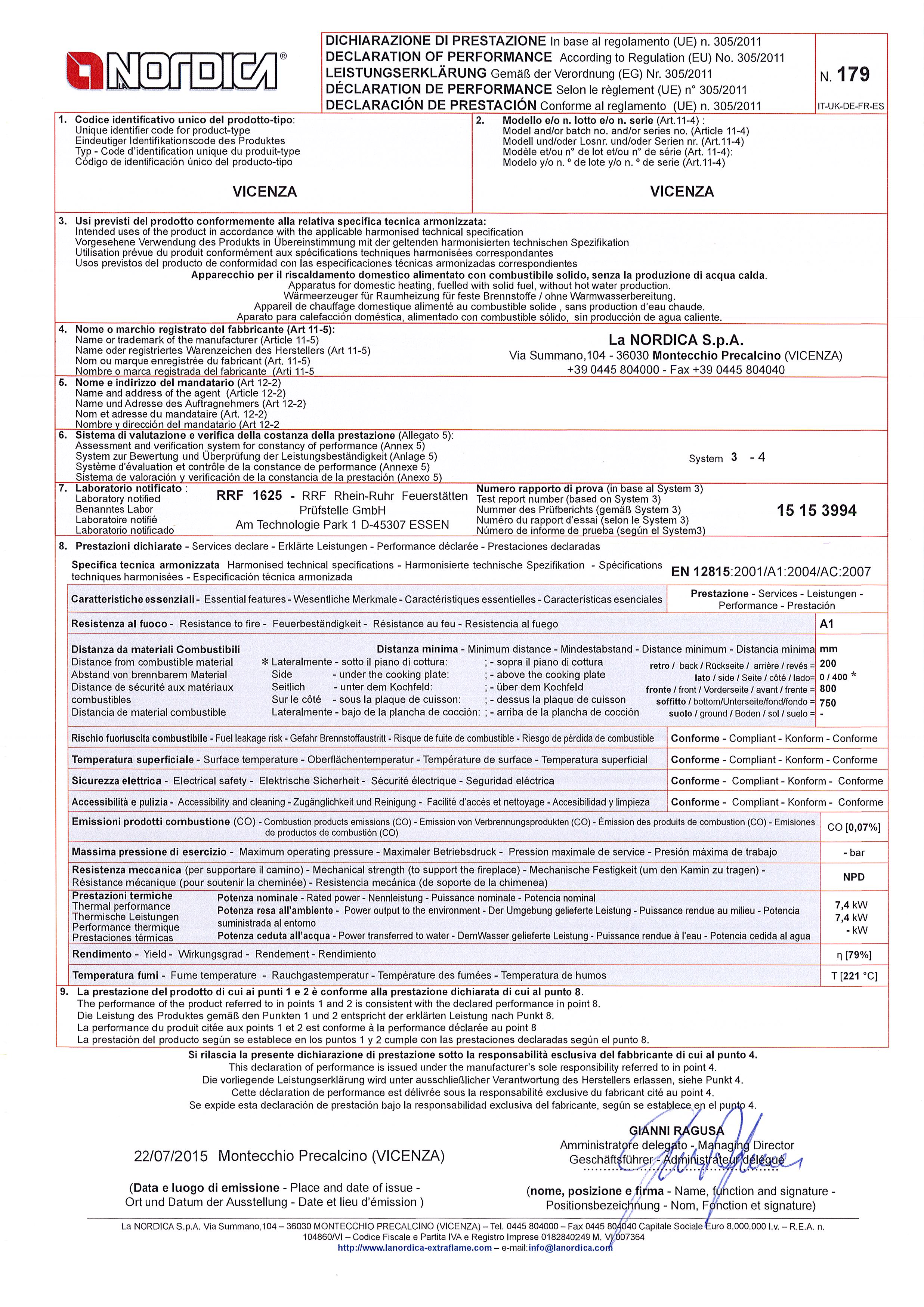
68
69 INFORMAZIONI MARCATURA CE - CE MARKING INFORMATION CE AUSZEICHNUNGSINFORMATIONEN - INFORMATIONS MARQUAGE CE INFORMACIÓN DE LA MARCA CE Ente notificato - Notified body - Benanntes Labor Laboratoire notifié - Laboratorio notificado DOP RRF EN VICENZA nr. 179 IT-UK-DE-FR -ES Distanza minima da materiali infiammabili Distance to adjacent combustible materials Mindestabstand zu brennbaren Materialen Distance minimum par rapport aux matériaux inflammables Distancia mínima a material inflamable * - sotto il piano di cottura / - sopra il piano di cottura - under the cooking plate / - above the cooking plate - unter dem Kochfeld / - über dem Kochfeld - sous la plaque de cuisson / - dessus la plaque de cuisson - bajo de la plancha de cocción / - arriba de la plancha de cocción Emissione di CO (13 % O 2 ) Emission of CO (13 % O 2 ) CO-Ausstoss bez.auf (13 % O 2 ) Émission de CO (13 % O 2 ) Emisión de CO (13 % O 2 ) Emissioni polveri (13 % O 2 ) Dust emissions (13 % O 2 ) Staubemissionen (13 % O 2 ) Émission de poudres (13 % O 2 ) Emisión de polvos (13 % O 2 ) Massima pressione idrica di esercizio ammessa Maximum operating pressure Maximale Betriebsdruck Pression hydrique de service maximum autorisée Máxima presión hídrica de funcionamiento admitida Temperatura gas di scarico Flue gas temperature Abgastemperatur Température gaz d échappement Temperatura del gas de escape Potenza termica nominale Thermal output Nennheizleistung Puissance thermique nominale Potencia térmica nominal Rendimento Energy efficiency Wirkungsgrad Rendement Rendimiento Tipi di combustibile Fuel types Brennstoffarten Types de combustible Tipos de combustible Retro / back / Rückseite / Arrière / Revés 200 mm Lato / Side / Seite / Côté / Lado 00 / mm 400 mm Fronte / Front / Vorderseite / Avant / Frente 800 mm Soffitto / Bottom / Unterseite / Fond / Fondo mm mm Suolo / Ground / Boden / Sol / Suelo - mm 0,07 % mg/nm 3 26 mg/nm 3 - bar 221 C 7,4 kw 79 % LEGNA WOOD HOLZ BOIS MADERA VKF - AEAI Nr. SINTEF Nr. 15a B-VG Nr. La NORDICA S.p.A. Via Summano, MONTECCHIO PRECALCINO (VICENZA) Tel Fax Capitale Sociale Euro I.v. R.E.A. n /VI Codice Fiscale e Partita IVA e Registro Imprese M. VI info@lanordica.com
70
71

72

73 INFORMAZIONI MARCATURA CE - CE MARKING INFORMATION CE AUSZEICHNUNGSINFORMATIONEN - INFORMATIONS MARQUAGE CE INFORMACIÓN DE LA MARCA CE Ente notificato - Notified body - Benanntes Labor Laboratoire notifié - Laboratorio notificado DOP TÜV TÜV Rheinland Energie und Umwelt Gmbh 15 EN VERONA nr. 180 IT-UK-DE-FR -ES Distanza minima da materiali infiammabili Distance to adjacent combustible materials Mindestabstand zu brennbaren Materialen Distance minimum par rapport aux matériaux inflammables Distancia mínima a material inflamable * - sotto il piano di cottura / - sopra il piano di cottura - under the cooking plate / - above the cooking plate - unter dem Kochfeld / - über dem Kochfeld - sous la plaque de cuisson / - dessus la plaque de cuisson - bajo de la plancha de cocción / - arriba de la plancha de cocción Emissione di CO (13 % O 2 ) Emission of CO (13 % O 2 ) CO-Ausstoss bez.auf (13 % O 2 ) Émission de CO (13 % O 2 ) Emisión de CO (13 % O 2 ) Emissioni polveri (13 % O 2 ) Dust emissions (13 % O 2 ) Staubemissionen (13 % O 2 ) Émission de poudres (13 % O 2 ) Emisión de polvos (13 % O 2 ) Massima pressione idrica di esercizio ammessa Maximum operating pressure Maximale Betriebsdruck Pression hydrique de service maximum autorisée Máxima presión hídrica de funcionamiento admitida Temperatura gas di scarico Flue gas temperature Abgastemperatur Température gaz d échappement Temperatura del gas de escape Potenza termica nominale Thermal output Nennheizleistung Puissance thermique nominale Potencia térmica nominal Rendimento Energy efficiency Wirkungsgrad Rendement Rendimiento Tipi di combustibile Fuel types Brennstoffarten Types de combustible Tipos de combustible Retro / back / Rückseite / Arrière / Revés 300 mm Lato / Side / Seite / Côté / Lado 00 / mm 400 mm Fronte / Front / Vorderseite / Avant / Frente 1000 mm Soffitto / Bottom / Unterseite / Fond / Fondo mm mm Suolo / Ground / Boden / Sol / Suelo - mm 0,05 % mg/nm 3 12 mg/nm 3 - bar 208 C 8 kw 78,4 % LEGNA WOOD HOLZ BOIS MADERA VKF - AEAI Nr. SINTEF Nr. 15a B-VG Nr. La NORDICA S.p.A. Via Summano, MONTECCHIO PRECALCINO (VICENZA) Tel Fax Capitale Sociale Euro I.v. R.E.A. n /VI Codice Fiscale e Partita IVA e Registro Imprese M. VI info@lanordica.com
Testata secondo / Tested according to / Geprüft nach / Certifié selon / : EN12815
 ISTRUZIONI PER L INSTALLAZIONE, L USO E LA MANUTENZIONE - IT INSTRUCTIONS FOR INSTALLATION, USE AND MAINTENANCE - EN ANWEISUNGEN FÜR DIE AUFSTELLUNG, DEN GEBRAUCH UND DIE WARTUNG - DE INSTRUCTIONS POUR
Testata secondo / Tested according to / Geprüft nach / Certifié selon / : EN12815
 ISTRUZIONI PER L INSTALLAZIONE, L USO E LA MANUTENZIONE - IT INSTRUCTIONS FOR INSTALLATION, USE AND MAINTENANCE - EN ANWEISUNGEN FÜR DIE AUFSTELLUNG, DEN GEBRAUCH UND DIE WARTUNG - DE INSTRUCTIONS POUR
Testata secondo / Tested according to / Geprüft nach / Certifié selon / : EN13229
 ISTRUZIONI PER L INSTALLAZIONE, L USO E LA MANUTENZIONE - IT INSTRUCTIONS FOR INSTALLATION, USE AND MAINTENANCE - EN ANWEISUNGEN FÜR DIE AUFSTELLUNG, DEN GEBRAUCH UND DIE WARTUNG - DE INSTRUCTIONS POUR
DICHIARAZIONE DI CONFORMITA DEL COSTRUTTORE
 ISTRUZIONI PER L INSTALLAZIONE, L USO E LA MANUTENZIONE - IT INSTRUCTIONS FOR INSTALLATION, USE AND MAINTENANCE - EN ANWEISUNGEN FÜR DIE AUFSTELLUNG, DEN GEBRAUCH UND DIE WARTUNG - DE INSTRUCTIONS POUR
Testata secondo / Tested according to / Geprüft nach / Certifié selon / : EN13240
 ISTRUZIONI PER L INSTALLAZIONE, L USO E LA MANUTENZIONE - IT INSTRUCTIONS FOR INSTALLATION, USE AND MAINTENANCE - EN ANWEISUNGEN FÜR DIE AUFSTELLUNG, DEN GEBRAUCH UND DIE WARTUNG - DE INSTRUCTIONS POUR
WANDA - Wanda Classic
 ISTRUZIONI PER L INSTALLAZIONE, L USO E LA MANUTENZIONE - IT INSTRUCTIONS FOR INSTALLATION, USE AND MAINTENANCE - EN ANWEISUNGEN FÜR DIE AUFSTELLUNG, DEN GEBRAUCH UND DIE WARTUNG - DE INSTRUCTIONS POUR
STUFA COMBINATA - COMBI STOVE - KOMBI-KAMINOFEN CLEO COMBI Bordeaux Vogue Fly
 ISTRUZIONI PER L INSTALLAZIONE, L USO E LA MANUTENZIONE -IT INSTRUCTIONS FOR INSTALLATION, USE AND MAINTENANCE - EN ANWEISUNGEN FÜR DIE AUFSTELLUNG, DEN GEBRAUCH UND DIE WARTUNG DE INSTRUCTIONS POUR L
STUFA A LEGNA MAJOR / MINOR MAX / JUNIOR
 S ISTRUZIONI PER L INSTALLAZIONE, L USO E LA MANUTENZIONE IT INSTRUCTIONS FOR INSTALLATION, USE AND MAINTENANCE EN ANWEISUNGEN FÜR DIE AUFSTELLUNG, DEN GEBRAUCH UND DIE WARTUNG DE STUFA A LEGNA MAJOR /
STUFA A LEGNA / CHIMNEY STOVE / HOLZOFEN KAMINOFEN DORELLA L8 DORELLA L12
 ISTRUZIONI PER L INSTALLAZIONE, L USO E LA MANUTENZIONE IT INSTRUCTIONS FOR INSTALLATION, USE AND MAINTENANCE - EN ANWEISUNGEN FÜR DIE AUFSTELLUNG, DEN GEBRAUCH UND DIE WARTUNG - DE STUFA A LEGNA / CHIMNEY
INSERTI IN GHISA H49
 ISTRUZIONI PER L INSTALLAZIONE, L USO E LA MANUTENZIONE - IT INSTRUCTIONS FOR INSTALLATION, USE AND MAINTENANCE - EN ANWEISUNGEN FÜR DIE AUFSTELLUNG, DEN GEBRAUCH UND DIE WARTUNG - DE INSTRUCTIONS POUR
CORTINA CORTINA Maiolica CORTINA FORNO CORTINA FORNO Maiolica
 ISTRUZIONI PER L INSTALLAZIONE, L USO E LA MANUTENZIONE IT INSTRUCTIONS FOR INSTALLATION, USE AND MAINTENANCE - EN ANWEISUNGEN FÜR DIE AUFSTELLUNG, DEN GEBRAUCH UND DIE WARTUNG - DE STUFA CAMINO / CHIMNEY
ROSSELLA PLUS / NICOLETTA ROSSELLA PLUS FORNO / NICOLETTA FORNO
 ISTRUZIONI PER L INSTALLAZIONE, L USO E LA MANUTENZIONE -IT INSTRUCTIONS FOR INSTALLATION, USE AND MAINTENANCE - EN ANWEISUNGEN FÜR DIE AUFSTELLUNG, DEN GEBRAUCH UND DIE WARTUNG - DE STUFA CAMINO / CHIMNEY
SUPER MAX / SUPER JUNIOR
 S ISTRUZIONI PER L INSTALLAZIONE, L USO E LA MANUTENZIONE IT INSTRUCTIONS FOR INSTALLATION, USE AND MAINTENANCE EN ANWEISUNGEN FÜR DIE AUFSTELLUNG, DEN GEBRAUCH UND DIE WARTUNG DE INSTRUCTION POUR L INSTALLATION,
STUFA CAMINO CHIMNEY STOVE KAMINOFEN CARILLON 4 : 3 CARILLON 16 : 9
 ISTRUZIONI PER L INSTALLAZIONE, L USO E LA MANUTENZIONE IT INSTRUCTIONS FOR INSTALLATION, USE AND MAINTENANCE - EN ANWEISUNGEN FÜR DIE AUFSTELLUNG, DEN GEBRAUCH UND DIE WARTUNG DE STUFA CAMINO CHIMNEY
STUFA A LEGNA / CHIMNEY STOVE / HOLZOFEN KAMINOFEN ROSSELLA R1 LOLA LUNA
 ISTRUZIONI PER L INSTALLAZIONE, L USO E LA MANUTENZIONE IT INSTRUCTIONS FOR INSTALLATION, USE AND MAINTENANCE - EN ANWEISUNGEN FÜR DIE AUFSTELLUNG, DEN GEBRAUCH UND DIE WARTUNG - DE STUFA A LEGNA / CHIMNEY
FLY IDRO DSA. Testata secondo / Tested according to / Geprüft nach / Certifié selon / : EN13240
 ISTRUZIONI PER L INSTALLAZIONE, L USO E LA MANUTENZIONE - IT INSTRUCTIONS FOR INSTALLATION, USE AND MAINTENANCE - EN ANWEISUNGEN FÜR DIE AUFSTELLUNG, DEN GEBRAUCH UND DIE WARTUNG - DE INSTRUCTIONS POUR
Termocucina / Wood burning stove/cooker / Heizungsherd TERMOROSA TR-02
 ISTRUZIONI PER L INSTALLAZIONE, L USO E LA MANUTENZIONE IT INSTALLATION, USER AND MAINTENANCE INSTRUCTIONS EN ANLEITUNG ZUR INSTALLATION, BENUTZUNG UND WARTUNG - DE Termocucina / Wood burning stove/cooker
CUCINA A LEGNA / WOOD COOKER / HAUSHALTHERD SOVRANA
 ISTRUZIONI PER L INSTALLAZIONE, L USO E LA MANUTENZIONE IT INSTRUCTIONS FOR INSTALLATION, USE AND MAINTENANCE - EN ANWEISUNGEN FÜR DIE AUFSTELLUNG, DEN GEBRAUCH UND DIE WARTUNG - DE CUCINA A LEGNA / WOOD
TERMOCUCINA / THERMOCOOKER / HEIZUNGSHERD TERMOSUPREMA Compact
 Termocucina / Thermocooker / Heizungsherd TERMOSUPREMA Compact ISTRUZIONI PER L INSTALLAZIONE, L USO E LA MANUTENZIONE IT INSTRUCTIONS FOR INSTALLATION, USE AND MAINTENANCE - EN ANWEISUNGEN FÜR DIE AUFSTELLUNG,
TermoRossella Plus DSA TermoNicoletta DSA TermoRossella Plus-forno DSA TermoNicoletta-forno DSA
 ISTRUZIONI PER L INSTALLAZIONE, L USO E LA MANUTENZIONE - IT INSTRUCTIONS FOR INSTALLATION, USE AND MAINTENANCE - EN ANWEISUNGEN FÜR DIE AUFSTELLUNG, DEN GEBRAUCH UND DIE WARTUNG - DE TermoRossella Plus
ITALY TERMO - BuILT In - DSA
 ISTRUZIONI PER L INSTALLAZIONE, L USO E LA MANUTENZIONE - IT INSTRUCTIONS FOR INSTALLATION, USE AND MAINTENANCE - EN ANWEISUNGEN FÜR DIE AUFSTELLUNG, DEN GEBRAUCH UND DIE WARTUNG - DE INSTRUCTIONS POUR
TERMOROSA DSA. Testata secondo / Tested according to / Geprüft nach / Testé selon: EN 12815
 ISTRUZIONI PER L INSTALLAZIONE, L USO E LA MANUTENZIONE -IT INSTRUCTIONS FOR INSTALLATION, USE AND MAINTENANCE - EN ANWEISUNGEN FÜR DIE AUFSTELLUNG, DEN GEBRAUCH UND DIE WARTUNG DE INSTRUCTIONS POUR L
NORMA S-EVO IDRO DSA / STEEL S-EVO IDRO DSA / CLASSIC S-EVO IDRO DSA
 ISTRUZIONI PER L INSTALLAZIONE, L USO E LA MANUTENZIONE - IT INSTRUCTIONS FOR INSTALLATION, USE AND MAINTENANCE - EN ANWEISUNGEN FÜR DIE AUFSTELLUNG, DEN GEBRAUCH UND DIE WARTUNG - DE INSTRUCTIONS POUR
ROSSELLA Plus / NICOLETTA / GISELLA Rossella Plus FORNO / Nicoletta FORNO
 ISTRUZIONI PER L INSTALLAZIONE, L USO E LA MANUTENZIONE -IT INSTRUCTIONS FOR INSTALLATION, USE AND MAINTENANCE - EN ANWEISUNGEN FÜR DIE AUFSTELLUNG, DEN GEBRAUCH UND DIE WARTUNG DE INSTRUCTIONS POUR L
FLY IDRO DSA. Testata secondo / Tested according to / Geprüft nach / Certifié selon / : EN12815: EN13240
 ISTRUZIONI PER L INSTALLAZIONE, L USO E LA MANUTENZIONE - IT INSTRUCTIONS FOR INSTALLATION, USE AND MAINTENANCE - EN ANWEISUNGEN FÜR DIE AUFSTELLUNG, DEN GEBRAUCH UND DIE WARTUNG - DE INSTRUCTIONS POUR
STEFANY Forno / SVEZIA New / NORVEGIA New
 ISTRUZIONI PER L INSTALLAZIONE, L USO E LA MANUTENZIONE IT INSTRUCTIONS FOR INSTALLATION, USE AND MAINTENANCE - EN ANWEISUNGEN FÜR DIE AUFSTELLUNG, DEN GEBRAUCH UND DIE WARTUNG - DE STUFA CAMINO / CHIMNEY
ISTRUZIONI PER L INSTALLAZIONE, L USO E LA MANUTENZIONE IT INSTRUCTIONS FOR INSTALLATION, USE AND MAINTENANCE - EN
 ISTRUZIONI PER L INSTALLAZIONE, L USO E LA MANUTENZIONE IT INSTRUCTIONS FOR INSTALLATION, USE AND MAINTENANCE - EN ANWEISUNGEN FÜR DIE AUFSTELLUNG, DEN GEBRAUCH UND DIE WARTUNG - DE TermoIsotta DSA Testata
STUFA A LEGNA SUPER MAX / SUPER JUNIOR
 S ISTRUZIONI PER L INSTALLAZIONE, L USO E LA MANUTENZIONE IT INSTRUCTIONS FOR INSTALLATION, USE AND MAINTENANCE EN ANWEISUNGEN FÜR DIE AUFSTELLUNG, DEN GEBRAUCH UND DIE WARTUNG DE STUFA A LEGNA SUPER MAX
TermoRossella Plus DSA TermoNicoletta DSA TermoRossella Plus forno DSA TermoNicoletta forno DSA
 ISTRUZIONI PER L INSTALLAZIONE, L USO E LA MANUTENZIONE - IT INSTRUCTIONS FOR INSTALLATION, USE AND MAINTENANCE - EN ANWEISUNGEN FÜR DIE AUFSTELLUNG, DEN GEBRAUCH UND DIE WARTUNG - DE INSTRUCTIONS POUR
TERMOISOTTA DSA. Testata secondo / Tested according to / Geprüft nach / Certifié selon / : EN13240
 ISTRUZIONI PER L INSTALLAZIONE, L USO E LA MANUTENZIONE - IT INSTRUCTIONS FOR INSTALLATION, USE AND MAINTENANCE - EN ANWEISUNGEN FÜR DIE AUFSTELLUNG, DEN GEBRAUCH UND DIE WARTUNG - DE INSTRUCTIONS POUR
TERMOSUPREMA COMPACT DSA
 ISTRUZIONI PER L INSTALLAZIONE, L USO E LA MANUTENZIONE - IT INSTRUCTIONS FOR INSTALLATION, USE AND MAINTENANCE - EN ANWEISUNGEN FÜR DIE AUFSTELLUNG, DEN GEBRAUCH UND DIE WARTUNG - DE INSTRUCTIONS POUR
ISTRUZIONI PER L INSTALLAZIONE, L USO E LA MANUTENZIONE - ITALIANO INSTRUCTIONS FOR INSTALLATION, USE AND MAINTENANCE EN
 ISTRUZIONI PER L INSTALLAZIONE, L USO E LA MANUTENZIONE - ITALIANO INSTRUCTIONS FOR INSTALLATION, USE AND MAINTENANCE EN ANLEITUNGEN ZUR INSTALLATION, DEM GEBRAUCH UND DER WARTUNG DEUTSCH TERMOCAMINO 650-800
NORMA-S IDRO DSA / STEEL / CLASSIC
 ISTRUZIONI PER L INSTALLAZIONE, L USO E LA MANUTENZIONE - IT INSTRUCTIONS FOR INSTALLATION, USE AND MAINTENANCE - EN ANWEISUNGEN FÜR DIE AUFSTELLUNG, DEN GEBRAUCH UND DIE WARTUNG - DE INSTRUCTIONS POUR
TermoRossella Plus DSA TermoNicoletta DSA TermoRossella Plus forno DSA TermoNicoletta forno DSA
 ISTRUZIONI PER L INSTALLAZIONE, L USO E LA MANUTENZIONE - IT INSTRUCTIONS FOR INSTALLATION, USE AND MAINTENANCE - EN ANWEISUNGEN FÜR DIE AUFSTELLUNG, DEN GEBRAUCH UND DIE WARTUNG - DE INSTRUCTIONS POUR
CUCINE. Componibilità Cucina senza gola Anbaufähigkeit Küche ohne Hohlkehle. Basi / Unterschränke H. 24/36/48/60. Basi / Unterschränke H.
 CUCINE Componibilità Cucina senza gola Anbaufähigkeit Küche ohne Hohlkehle Basi / Unterschränke H. 24/36/48/60 Basi / Unterschränke H. 72 Basi / Unterschränke H. 84 18 KÜCHEN Componibilità Cucina senza
TERMOCUCINA / THERMOCOOKER / HEIZUNGSHERD TERMOSUPREMA Compact - DSA
 Termocucina / Thermocooker / Heizungsherd TERMOSUPREMA Compact DSA ISTRUZIONI PER L INSTALLAZIONE, L USO E LA MANUTENZIONE IT INSTRUCTIONS FOR INSTALLATION, USE AND MAINTENANCE - EN ANWEISUNGEN FÜR DIE
STUFA CAMINO / CHIMNEY STOVE / KAMINOFEN OMBRETTA OMBRETTA FORNO / CARLOTTA CARLOTTA - FORNO
 ISTRUZIONI PER L INSTALLAZIONE, L USO E LA MANUTENZIONE IT INSTRUCTIONS FOR INSTALLATION, USE AND MAINTENANCE - EN ANWEISUNGEN FÜR DIE AUFSTELLUNG, DEN GEBRAUCH UND DIE WARTUNG - DE STUFA CAMINO / CHIMNEY
MONOBLOCCO 500 ANGOLO - 800 ANGOLO
 ISTRUZIONI PER L INSTALLAZIONE, L USO E LA MANUTENZIONE - IT INSTRUCTIONS FOR INSTALLATION, USE AND MAINTENANCE - EN ANWEISUNGEN FÜR DIE AUFSTELLUNG, DEN GEBRAUCH UND DIE WARTUNG - DE INSTRUCTIONS POUR
ITALIANO... 5 ENGLISH DEUTSCH FRANCAIS ESPAOL... 69
 IT UK DE FR ES MANUALE UTENTE PRODOTTI a legna WOOD PRODUCTs USER MANUAL BENUTZERHANDBUCH HOLZprodukt MANUEL UTILISATEUR produits $)A ($ BOIS MANUAL DEL USUARIO PRODUCTOs de lea MADE IN ITALY design &
FIAMMETTA - ASIA GIORGIA - FIORELLA
 ISTRUZIONI PER L INSTALLAZIONE, L USO E LA MANUTENZIONE IT INSTRUCTIONS FOR INSTALLATION, USE AND MAINTENANCE - EN ANWEISUNGEN FÜR DIE AUFSTELLUNG, DEN GEBRAUCH UND DIE WARTUNG - DE STUFA CAMINO / CHIMNEY
Rev.06 $)G!9 IT!9 EN!9 DE!9 FR
G!9 IT!9 EN!9 DE!9 FR") ISTRUZIONI PER L $)A!/ INSTALLAZIONE, L!/ USO E LA MANUTENZIONE $)G!9 IT INSTRUCTIONS FOR INSTALLATION, USE AND MAINTENANCE $)G!9 EN ANWEISUNGEN FR DIE AUFSTELLUNG, DEN GEBRAUCH UND DIE WARTUNG $)G!9 DE
ISTRUZIONI PER L $)A!/ INSTALLAZIONE, L!/ USO E LA MANUTENZIONE $)G!9 IT INSTRUCTIONS FOR INSTALLATION, USE AND MAINTENANCE $)G!9 EN ANWEISUNGEN FR DIE AUFSTELLUNG, DEN GEBRAUCH UND DIE WARTUNG $)G!9 DE
INSERTO CRYSTAL 50-50V BII - 50V P EVO - 100
 ISTRUZIONI PER L INSTALLAZIONE, L USO E LA MANUTENZIONE - IT INSTRUCTIONS FOR INSTALLATION, USE AND MAINTENANCE - EN ANWEISUNGEN FÜR DIE AUFSTELLUNG, DEN GEBRAUCH UND DIE WARTUNG - DE INSTRUCTIONS POUR
ITALY TERMO - BUILT IN - DSA
 ISTRUZIONI PER L INSTALLAZIONE, L USO E LA MANUTENZIONE - IT INSTRUCTIONS FOR INSTALLATION, USE AND MAINTENANCE - EN ANWEISUNGEN FÜR DIE AUFSTELLUNG, DEN GEBRAUCH UND DIE WARTUNG - DE INSTRUCTIONS POUR
TERMOROSA - DSA. Testata secondo / Tested according to / Geprüft nach / Certifié selon / : EN12815
 ISTRUZIONI PER L INSTALLAZIONE, L USO E LA MANUTENZIONE - IT INSTRUCTIONS FOR INSTALLATION, USE AND MAINTENANCE - EN ANWEISUNGEN FÜR DIE AUFSTELLUNG, DEN GEBRAUCH UND DIE WARTUNG - DE INSTRUCTIONS POUR
ITALY TERMO - BUILT IN - DSA
 ISTRUZIONI PER L INSTALLAZIONE, L USO E LA MANUTENZIONE - IT INSTRUCTIONS FOR INSTALLATION, USE AND MAINTENANCE - EN ANWEISUNGEN FÜR DIE AUFSTELLUNG, DEN GEBRAUCH UND DIE WARTUNG - DE INSTRUCTIONS POUR
TERMOCUCINOTTA EVO DSA - TERMOCUCINOTTA DSA
 ISTRUZIONI PER L INSTALLAZIONE, L USO E LA MANUTENZIONE - IT INSTRUCTIONS FOR INSTALLATION, USE AND MAINTENANCE - EN ANWEISUNGEN FÜR DIE AUFSTELLUNG, DEN GEBRAUCH UND DIE WARTUNG - DE INSTRUCTIONS POUR
FULVIA Fulvia forno GAIA Gaia forno
 ISTRUZIONI PER L INSTALLAZIONE, L USO E LA MANUTENZIONE IT INSTRUCTIONS FOR INSTALLATION, USE AND MAINTENANCE - EN ANWEISUNGEN FÜR DIE AUFSTELLUNG, DEN GEBRAUCH UND DIE WARTUNG - DE INSTRUCTIONS POUR L
STUFA CAMINO CHIMNEY STOVE KAMINOFEN ELLIPSE
 ISTRUZIONI PER L INSTALLAZIONE, L USO E LA MANUTENZIONE IT INSTRUCTIONS FOR INSTALLATION, USE AND MAINTENANCE - EN ANWEISUNGEN FÜR DIE AUFSTELLUNG, DEN GEBRAUCH UND DIE WARTUNG DE STUFA CAMINO CHIMNEY
Sunpower 150W Inverter
 Sunpower 150W Inverter S U N P O W E R 1 5 0 W I N V E R T E R Einleitung Ein Inverter ist ein elektronisches Gerät, das eine niedrige Spannung von 12V-DC Stromstärke, wie zum Beispiel von einer Batterie
TERMOCAMINO Testato secondo/ Tested according to / Getestet gemäß / Testé selon : EN 13229
 ISTRUZIONI PER L INSTALLAZIONE, L USO E LA MANUTENZIONE - IT INSTRUCTIONS FOR INSTALLATION, USE AND MAINTENANCE - EN ANWEISUNGEN FÜR DIE AUFSTELLUNG, DEN GEBRAUCH UND DIE WARTUNG - DE INSTRUCTIONS POUR
PURASCA. 4-Zimmer. Zimmer-Haus zum Ausbauen Casa con 4 locali da riattare. Fr. 170' Mit Nebengebäude im Dorfkern Con stalla a canto nel nucleo
 PURASCA 4-Zimmer Zimmer-Haus zum Ausbauen Casa con 4 locali da riattare Mit Nebengebäude im Dorfkern Con stalla a canto nel nucleo Fr. 170'000.-- 4180/402 Ubicazione Regione: Malcantone NAP/Località: 6989
Istruzioni d uso Gebrauchsanweisung Instructions Manuel d utilisation
 Istruzioni d uso Gebrauchsanweisung Instructions Manuel d utilisation ITALIANO Disposizioni pag. 2 Installazione pag. 4 Uso pag. 13 Manutenzione pag. 20 Cosa fare se... pag. 25 Dati tecnici pag. 26 Garanzia
STUFA CAMINO / CHIMNEY STOVE / KAMINOFEN Giulietta / Isetta-07 / Isotta-07 Isetta-07 cerchi / Isotta-07 cerchi
 ISTRUZIONI PER L INSTALLAZIONE, L USO E LA MANUTENZIONE IT INSTRUCTIONS FOR INSTALLATION, USE AND MAINTENANCE - EN ANWEISUNGEN FÜR DIE AUFSTELLUNG, DEN GEBRAUCH UND DIE WARTUNG - DE STUFA CAMINO / CHIMNEY
abluftrohrsysteme sistemi di areazione
 abluftrohrsysteme sistemi di areazione abluftrohrsysteme sistemi di areazione aeroboy aeroboy spart clever energie aktiv energie sparen. keine windgeräusche, kein klappern von lamellen und keine insekten
TermoCAMINO BASE - DSA
 ISTRUZIONI PER L INSTALLAZIONE, L USO E LA MANUTENZIONE -IT INSTRUCTIONS FOR INSTALLATION, USE AND MAINTENANCE - EN ANWEISUNGEN FÜR DIE AUFSTELLUNG, DEN GEBRAUCH UND DIE WARTUNG DE INSTRUCTIONS POUR L
CUCINA A FUOCO CONTINUO - WOOD COOKER - DAUERBRANDHERD ROSA ROSETTA
 ISTRUZIONI PER L INSTALLAZIONE, L USO E LA MANUTENZIONE IT INSTRUCTIONS FOR INSTALLATION, USE AND MAINTENANCE EN AUFSTELL- UND BEDIENUNGSANLEITUNG DE CUCINA A FUOCO CONTINUO - WOOD COOKER - DAUERBRANDHERD
Termo Isotta DSA. Testata secondo / Tested according to / Geprüft nach / Testé selon EN 13240
 ISTRUZIONI PER L INSTALLAZIONE, L USO E LA MANUTENZIONE - IT INSTRUCTIONS FOR INSTALLATION, USE AND MAINTENANCE - EN ANWEISUNGEN FÜR DIE AUFSTELLUNG, DEN GEBRAUCH UND DIE WARTUNG - DE INSTRUCTIONS POUR
INSERTO Crystal 50-50v - 50v p
 ISTRUZIONI PER L INSTALLAZIONE, L USO E LA MANUTENZIONE IT INSTRUCTIONS FOR INSTALLATION, USE AND MAINTENANCE EN ANWEISUNGEN FÜR DIE AUFSTELLUNG, DEN GEBRAUCH UND DIE WARTUNG DE INSTRUCTIONS POUR L INSTALLATION,
FOCOLARE 80 IDRO CRYSTAL - DSA
 ISTRUZIONI PER L INSTALLAZIONE, L USO E LA MANUTENZIONE - IT INSTRUCTIONS FOR INSTALLATION, USE AND MAINTENANCE - EN ANWEISUNGEN FÜR DIE AUFSTELLUNG, DEN GEBRAUCH UND DIE WARTUNG - DE INSTRUCTIONS POUR
INSERTO SECONDO - ACCORDING TO - NACH DIN EN13229
 ISTRUZIONI PER L INSTALLAZIONE, L USO E LA MANUTENZIONE - IT INSTRUCTIONS FOR INSTALLATION, USE AND MAINTENANCE - EN ANWEISUNGEN FÜR DIE AUFSTELLUNG, DEN GEBRAUCH UND DIE WARTUNG - DE INSERTO 50 80 100
MARA. Montageanleitung Mounting Instructions Istruzioni di montaggio. Abmessungen / Dimensions / Dimensioni
 Abmessungen / Dimensions / Dimensioni 6 107 10 75 50 90 90 1 1 1 98 42 30 42 1 1 Leuchtmittelwechsel/Insert bulbs/sostituzione lampadine Vor Auswechseln jeder Lampe und vor jedem Verstellen einer Leuchte
TERMOCAMINO WF25 DSA - WF25X DSA - WF Plus DSA
 ISTRUZIONI PER L INSTALLAZIONE, L USO E LA MANUTENZIONE - IT INSTRUCTIONS FOR INSTALLATION, USE AND MAINTENANCE - EN ANWEISUNGEN FÜR DIE AUFSTELLUNG, DEN GEBRAUCH UND DIE WARTUNG - DE INSTRUCTIONS POUR
 ISTRUZIONI PER L $)A!/ INSTALLAZIONE, L!/ USO E LA MANUTENZIONE - IT INSTRUCTIONS FOR INSTALLATION, USE AND MAINTENANCE - EN ANWEISUNGEN FR DIE AUFSTELLUNG, DEN GEBRAUCH UND DIE WARTUNG - DE INSTRUCTIONS
Wasserkraft. Energia idraulica
 Wasserkraft Energia idraulica Energie aus der Kraft des Wassers Energia tratta dalla forza dell acqua Mit Wasserkraftwerken werden weltweit knapp 18% der elektrischen Energie erzeugt. Die Wasserkraft liegt
MONOBLOCCO 400 PIANO - 500 ANGOLO 800 ANGOLO / Dx - Sx
 ISTRUZIONI PER L INSTALLAZIONE, L USO E LA MANUTENZIONE -IT INSTRUCTIONS FOR INSTALLATION, USE AND MAINTENANCE - EN ANWEISUNGEN FÜR DIE AUFSTELLUNG, DEN GEBRAUCH UND DIE WARTUNG DE INSTRUCTIONS POUR L
STUFA A LEGNA / CHIMNEY STOVE / HOLZOFEN KAMINOFEN ROSSELLA R1 LOLA LUNA
 ISTRUZIONI PER L INSTALLAZIONE, L USO E LA MANUTENZIONE IT INSTRUCTIONS FOR INSTALLATION, USE AND MAINTENANCE - EN ANWEISUNGEN FÜR DIE AUFSTELLUNG, DEN GEBRAUCH UND DIE WARTUNG - DE STUFA A LEGNA / CHIMNEY
GRESSO. Zimmer-Ferienhaus Casa di vacanza con 3 locali. An ruhiger, sonniger Aussichtslage Posizione tranquilla, soleggiata e bella vista
 GRESSO 3-Zimmer Zimmer-Ferienhaus Casa di vacanza con 3 locali An ruhiger, sonniger Aussichtslage Posizione tranquilla, soleggiata e bella vista 4180/265 Fr. 105'000.-- GEIERSBERGER T - Ubicazione Regione:
MONOBLOCCO 400 PIANO ANGOLO 800 ANGOLO / Dx - Sx
 ISTRUZIONI PER L INSTALLAZIONE, L USO E LA MANUTENZIONE IT INSTRUCTIONS FOR INSTALLATION, USE AND MAINTENANCE EN ANWEISUNGEN FÜR DIE AUFSTELLUNG, DEN GEBRAUCH UND DIE WARTUNG DE NOTICE D'INSTALLATION ET
FILO LED FILO. Montageanleitung Mounting Instructions Istruzioni di montaggio. Abmessungen / Dimensions / Dimensioni FILO 135 LED FILO 135
 Abmessungen / Dimensions / Dimensioni FILO 135 LED FILO 135 FILO 190 LED FILO 190 FILO 260 Bei den quadratischen Abdeckungen ist auf die richtige Ausrichtung der Befestigungslöcher unbedingt zu achten!
VELA ROUND. Montageanleitung Mounting Instructions Istruzioni di montaggio
 VELA ROUND WALL 170 VELA ROUND WALL 260 VELA ROUND WALL 350 VELA ROUND WALL 450 20 73,6 30 35 105 10 50 55 75 75 40 42,5 95 40 105 VELA ROUND CEILING 170 VELA ROUND CEILING 260 VELA ROUND CEILING 350 VELA
Dichiarazione delle caratteristiche prestazionali Schüco di cui alla norma DIN EN :
 Schüco ThermoSlide SI 82 Sistemi in PVC Porte e finestre Dichiarazione delle caratteristiche prestazionali Schüco di cui alla norma DIN EN 14351-1:2016-12 Valida fino al 01/02/2019 Schüco 1 Sistema Schüco
SPORT HOOD. Dodge Ram Sport A 3. Graphic Premask 2. Graphic. Graphic Liner. - Tape. Description. Quanity. Call Out. Side 4. Hood.
 1 SPORT HOOD Dodge Ram Sport www.mopar.com 4 5 A 3 Graphic Premask 2 Graphic A A 1 Graphic Liner - Tape Call Out Description Quanity Side 4 Hood PS 1 Hood 5 Hood DR 1 Hood 03/06/2015 K6862423 2 3 4 5 ISTRUZIONI
FOCOLARI IN GHISA. Testato secondo / Tested according to / Geprüft nach / Testé conformément à la : EN13229
 - ISTRUZIONI PER L INSTALLAZIONE, L USO E LA MANUTENZIONE IT INSTRUCTIONS FOR INSTALLATION, USE AND MAINTENANCE EN ANWEISUNGEN FÜR DIE AUFSTELLUNG, DEN GEBRAUCH UND DIE WARTUNG DE INSTRUCTIONS POUR L INSTALLATION,
BODY STRIPE CURVE. Fiat 500X. Description. Quanity. Call Out. Side 1. Driver. Driver Front Piece. 2 Driver Rear Piece 1 Driver
 1 BODY STRIPE CURVE Fiat 500X www.mopar.com 1 2 3 4 Call Out Description Quanity Side 1 Driver Front Piece 1 Driver 2 Driver Rear Piece 1 Driver 3 Passenger Front Piece 1 Passenger 4 Passenger Rear Piece
NORME DI SICUREZZA SUGLI APPARECCHI
 ISTRUZIONI PER L INSTALLAZIONE, L USO E LA MANUTENZIONE IT INSTRUCTIONS FOR INSTALLATION, USE AND MAINTENANCE EN ANWEISUNGEN FÜR DIE AUFSTELLUNG, DEN GEBRAUCH UND DIE WARTUNG DE INSTRUCTIONS POUR L INSTALLATION,
NORME DI SICUREZZA SUGLI APPARECCHI
 ISTRUZIONI PER L INSTALLAZIONE, L USO E LA MANUTENZIONE IT INSTRUCTIONS FOR INSTALLATION, USE AND MAINTENANCE EN ANWEISUNGEN FÜR DIE AUFSTELLUNG, DEN GEBRAUCH UND DIE WARTUNG DE INSTRUCTIONS POUR L INSTALLATION,
AZB 697. Deutsch. Italiano
 7 719 001 8 6 720 604 990 (99.04) OSW 19.1 19.2 19.3 19.4 6 720 604 990-00.1O Deutsch Italiano Getrenntrohranschluß Ø 80 mm für ZSBR/ZWBR 7, 11-25 A und ZSBR 3, 5-12 A Die einwandfreie Funktion ist nur
Schnellstartanleitung Revisionsumgehung 6/10kVA, Art.-Nr. HU10kVA-RACK
 Schnellstartanleitung Revisionsumgehung 6/10kVA, Art.-Nr. HU10kVA-RACK Produktbeschreibung Die Revisionsumgehung ermöglicht die Wartung oder den Batteriewechsel an der USV-Anlage ohne Abschalten der angeschlossenen
Natürlich geschützt! Naturalmente protetto!
 Natürlich geschützt! Naturalmente protetto! HOLZVERSIEGELUNGEN FiniturE per Legno PICHLERTOP Farblose einkomponentige Holzversiegelung auf fluorierter Harzbasis für vertikale Holzoberflächen. Finitura
TERMOROSA READY DSA - TEMOROSA xxl READY DSA
 ISTRUZIONI PER L INSTALLAZIONE, L USO E LA MANUTENZIONE - IT INSTRUCTIONS FOR INSTALLATION, USE AND MAINTENANCE - EN ANWEISUNGEN FÜR DIE AUFSTELLUNG, DEN GEBRAUCH UND DIE WARTUNG - DE INSTRUCTIONS POUR
 Unwesentliche Abänderung des Durchführungsplanes für die Wohnbauzone "B1 Mosergassl" Variazione non sostanziale al piano di attuazione per la zona residenziale "B1 Mosergassl" TECHNISCHER BERICHT RELAZIONE
CERENTINO. Zimmer-Rustico mit Wiesland Rustico di 3 ½ locali con prato
 Das Immobilienportal der Schweizer Makler. CERENTINO 3 ½-Zimmer Zimmer-Rustico mit Wiesland Rustico di 3 ½ locali con prato An sehr ruhiger, sonniger Aussichtslage In posizione molto tranquilla, soleggiata
Klinikfälle. Presentazione Casi. Volumen #2 Volume #2. Dr. Pablo Echarri
 Klinikfälle Volumen #2 Volume #2 Fälle in Kombination mit Clear Aligner im OK und festsitzender KFO im UK. Presentazione Casi Casi in cui è stato combinato l'aligner superiore trasparente con l'ortodonzia
Istruzioni d uso Gebrauchsanweisung Instructions Manuel d utilisation
 Istruzioni d uso Gebrauchsanweisung Instructions Manuel d utilisation ITALIANO Avvertenze pag. 2 Installazione pag. 5 Impianto di riscaldamento pag. 13 Uso pag. 18 Manutenzione pag. 22 Cosa fare se...
Regolatori di portata costante
 VK Descrizione Regolatori manuali di portata costante che agevolano la regolazione nei sistemi di ventilazione grazie alla preteratura della portata. Telaio in lamiera zincata. Il volume di portata desiderata
INSERTI IN GHISA CAST IRON INSERTS GUSSEISERNE EINSÄTZE
 ISTRUZIONI PER L INSTALLAZIONE, L USO E LA MANUTENZIONE IT INSTRUCTIONS FOR INSTALLATION, USE AND MAINTENANCE EN ANWEISUNGEN FÜR DIE AUFSTELLUNG, DEN GEBRAUCH UND DIE WARTUNG - DE INSERTI IN GHISA CAST
S.NAZZARO. 4-Familienhaus. casa piufamiliare di 4 appartamenti. Fr. 1 360 000.-- an herrlicher Panoramaseeblicklage. con bellissima vista sul lago
 S.NAZZARO 4-Familienhaus an herrlicher Panoramaseeblicklage.. casa piufamiliare di 4 appartamenti con bellissima vista sul lago Fr. 1 360 000.-- 4180/1702 Ubicazione Regione: Gambarogno Località: 6575
RONCAPIANO. Zimmer-Haus mit Garten Casa con 4 ½ locali con giardino
 Das Immobilienportal der Schweizer Makler. RONCAPIANO 4 ½-Zimmer Zimmer-Haus mit Garten Casa con 4 ½ locali con giardino An sehr ruhiger, sonniger Aussichtslage Posizione molto tranquilla e soleggiata
PREFABBRICATI IN CALCESTRUZZO BETONFERTIGTEILE Aldo Larcher Srl - GmbH Via Artigiani 5 Handwerkerstrasse I Appiano (BZ) Eppan
 Eppan") ISTRUZIONI PER L INSTALLAZIONE, FUNZIONAMENTO E MANUTENZIONE DI VASCHE PER ACQUE METEORICHE A TENUTA STAGNA ANLEITUNG FÜR DIE INSTALLATION, INBETRIEBNAHME UND WARTUNG VON WASSERDICHTEN REGENWASSERBEHÄLTERN
ISTRUZIONI PER L INSTALLAZIONE, FUNZIONAMENTO E MANUTENZIONE DI VASCHE PER ACQUE METEORICHE A TENUTA STAGNA ANLEITUNG FÜR DIE INSTALLATION, INBETRIEBNAHME UND WARTUNG VON WASSERDICHTEN REGENWASSERBEHÄLTERN
Renovierungszentrum Centro ristrutturazioni CasaBagno
 Renovierungszentrum Centro ristrutturazioni CasaBagno 40 Wohnungen - Bäder - Hotels - Geschäfte Appartamenti - Bagni - Hotel - Negozi 40 Das Unternehmen L azienda Seit 40 Jahren führt Ideacasabagno mit
APPARTAMENTI SCALATE DI SOPRA WOHNUNGEN SCALATE DI SOPRA
 Connesso Lago Maggiore APPARTAMENTI SCALATE DI SOPRA WOHNUNGEN SCALATE DI SOPRA BENVENUTI AL SOLE - WILLKOMMEN AN DER SONNE 2 SITO PARTICELLA PROGETTO PIANI SINTESI CONTATTO 3 5 6 7 10 11 SITO - LAGE 3
Mamma e papà, il mio abbigliamento da sci è importante per non soffrire il freddo!
 Total Ski and Fun Mamma e papà, il mio abbigliamento da sci è importante per non soffrire il freddo! Mami und Papi, meine Skibekleidung ist wichtig damit ich nicht friere! Guanti da sci Skihandschuhe Giaccone
CASTIONE della Presolana
 Das Immobilienportal der Schweizer Makler. CASTIONE della Presolana Mehrfamilienhaus (Chalet) Case plurifamiliare (Chalet) Mit fünf Wohnungen an sehr ruhiger, sonniger Lage 5 app. in posizione molto tranquilla
CLASSIC altezza 70 cm base diametro 20 cm. Art. 2037
 IL BIO CAMINO 2037 2006 2005 2017 2003 2007 2004 2001 2008 2002 2033 2031 Classic CLASSIC altezza 70 cm base diametro 20 cm Art. 2037 LUXORY LUXORY altezza 74 cm base 17x17x17 cm Art. 2017 OCTAGON OCTAGON
MACHBARKEITSSTUDIE MIT BERICHT
 Gemeinde Eppan an der Weinstraße Comune di Appiano sulla strada del vino Bau eines Trainingsplatzes, eines Dienstleistungsgebäudes, von Tribünen, eines Parkplatzes und einer Zufahrtsstraße zum Parkplatz
BRISSAGO. Ladenlokal in Patrizierhaus. negozio in una casa ticinese. Fr. 700 000.-- an zentraler Lage... in un posizione centrale 4180/1888
 BRISSAGO Ladenlokal in Patrizierhaus an zentraler Lage....... negozio in una casa ticinese in un posizione centrale Fr. 700 000.-- 4180/1888 Ubicazione Regione: Locarnese Località: 6614 Brissago, Via Leoncavallo
GORDOLA. 3-Zimmer-Rustico zum Ausbauen. mit Pergola an schöner Aussichtslage ... rustico di 3 locali da riattare. con pergola e bella vista
 Das Immobilienportal der Schweizer Makler. GORDOLA 3-Zimmer-Rustico zum Ausbauen mit Pergola an schöner Aussichtslage......... rustico di 3 locali da riattare con pergola e bella vista Fr. 155 000.-- 4180/2443
Istruzioni d uso Gebrauchsanweisung Instructions Manuel d utilisation
 Istruzioni d uso Gebrauchsanweisung Instructions Manuel d utilisation ITALIANO Avvertenze pag. 2 Installazione pag. 5 Uso pag. 13 Manutenzione pag. 16 Cosa fare se... pag. 19 Dati tecnici pag. 20 Garanzia
DURCHFÜHRUNGSBESTIMMUNGEN. Art. 1 ALLGEMEINE BESTIMMUNGEN
 DURCHFÜHRUNGSBESTIMMUNGEN Art. 1 ALLGEMEINE BESTIMMUNGEN Die allgemeinen Bestimmungen sind den Durchführungsbestimmungen zum Bauleitplan zu entnehmen. Die im Rechtsplan angeführten Angaben sind bindend.