System Board User s Manual
|
|
|
- Dominic Jaeger
- vor 8 Jahren
- Abrufe
Transkript
1 System Board User s Manual 935-X48T26-005G ALB E

2 Copyright This publication contains information that is protected by copyright. No part of it may be reproduced in any form or by any means or used to make any transformation/adaptation without the prior written permission from the copyright holders. This publication is provided for informational purposes only. The manufacturer makes no representations or warranties with respect to the contents or use of this manual and specifically disclaims any express or implied warranties of merchantability or fitness for any particular purpose. The user will assume the entire risk of the use or the results of the use of this document. Further, the manufacturer reserves the right to revise this publication and make changes to its contents at any time, without obligation to notify any person or entity of such revisions or changes All Rights Reserved. Trademarks Windows 2000 and Windows XP are registered trademarks of Microsoft Corporation. Award is a registered trademark of Award Software, Inc. Other trademarks and registered trademarks of products appearing in this manual are the properties of their respective holders. FCC and DOC Statement on Class B This equipment has been tested and found to comply with the limits for a Class B digital device, pursuant to Part 5 of the FCC rules. These limits are designed to provide reasonable protection against harmful interference when the equipment is operated in a residential installation. This equipment generates, uses and can radiate radio frequency energy and, if not installed and used in accordance with the instruction manual, may cause harmful interference to radio communications. However, there is no guarantee that interference will not occur in a particular installation. If this equipment does cause harmful interference to radio or television reception, which can be determined by turning the equipment off and on, the user is encouraged to try to correct the interference by one or more of the following measures: Reorient or relocate the receiving antenna. Increase the separation between the equipment and the receiver. Connect the equipment into an outlet on a circuit different from that to which the receiver is connected. Consult the dealer or an experienced radio TV technician for help. Notice:. The changes or modifications not expressly approved by the party responsible for compliance could void the user's authority to operate the equipment. 2. Shielded interface cables must be used in order to comply with the emission limits.

3 Table of Contents About this Manual... Warranty... Static Electricity Precaution... Safety Measures... About the Package... Before Using the System Board... System Board Layout... English... Français... Deutsch... Español Traditional Chinese... 07

4 Introduction About this Manual An electronic file of this manual is included in the CD. To view the user s manual in the CD, insert the CD into a CD-ROM drive. The autorun screen (Main Board Utility CD) will appear. Click the TOOLS icon then click Manual on the main menu. Warranty. Warranty does not cover damages or failures that arised from misuse of the product, inability to use the product, unauthorized replacement or alteration of components and product specifications. 2. The warranty is void if the product has been subjected to physical abuse, improper installation, modification, accidents or unauthorized repair of the product. 3. Unless otherwise instructed in this user s manual, the user may not, under any circumstances, attempt to perform service, adjustments or repairs on the product, whether in or out of warranty. It must be returned to the purchase point, factory or authorized service agency for all such work. 4. We will not be liable for any indirect, special, incidental or consequencial damages to the product that has been modified or altered. 4

5 Introduction Static Electricity Precautions It is quite easy to inadvertently damage your PC, system board, components or devices even before installing them in your system unit. Static electrical discharge can damage computer components without causing any signs of physical damage. You must take extra care in handling them to ensure against electrostatic build-up.. To prevent electrostatic build-up, leave the system board in its anti-static bag until you are ready to install it. 2. Wear an antistatic wrist strap. 3. Do all preparation work on a static-free surface. 4. Hold the device only by its edges. Be careful not to touch any of the components, contacts or connections. 5. Avoid touching the pins or contacts on all modules and connectors. Hold modules or connectors by their ends. Safety Measures Important: Electrostatic discharge (ESD) can damage your processor, disk drive and other components. Perform the upgrade instruction procedures described at an ESD workstation only. If such a station is not available, you can provide some ESD protection by wearing an antistatic wrist strap and attaching it to a metal part of the system chassis. If a wrist strap is unavailable, establish and maintain contact with the system chassis throughout any procedures requiring ESD protection. To avoid damage to the system: Use the correct AC input voltage range. To reduce the risk of electric shock: Unplug the power cord before removing the system chassis cover for installation or servicing. After installation or servicing, cover the system chassis before plugging the power cord. Battery: Danger of explosion if battery incorrectly replaced. Replace only with the same or equivalent type recommend by the manufacturer. Dispose of used batteries according to local ordinance. 5

6 Introduction About the Package The system board package contains the following items. If any of these items are missing or damaged, please contact your dealer or sales representative for assistance. The system board A user s manual One IDE cable One FDD cable Two Serial ATA data cables One power cable with 2 Serial ATA power connectors One RAID floppy diskette One I/O shield One Mainboard Utility CD The system board and accessories in the package may not come similar to the information listed above. This may differ in accordance to the sales region or models in which it was sold. For more information about the standard package in your region, please contact your dealer or sales representative. Before Using the System Board Before using the system board, prepare basic system components. If you are installing the system board in a new system, you will need at least the following internal components. A CPU Memory module Storage devices such as hard disk drive, CD-ROM, etc. You will also need external system peripherals you intend to use which will normally include at least a keyboard, a mouse and a video display monitor. 6

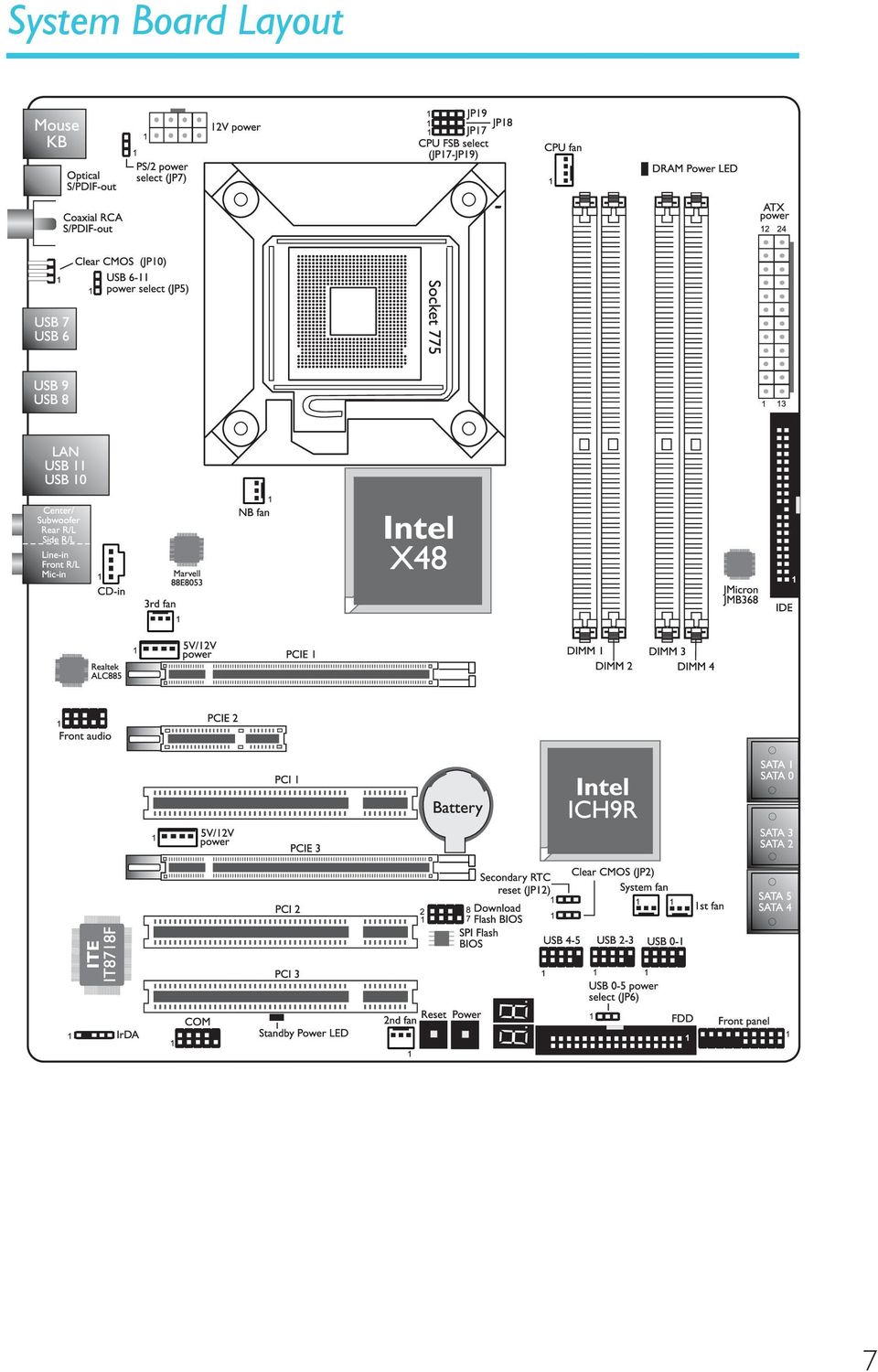
7 Introduction System Board Layout 7
8 E English Chapter - Introduction English Specifications Processor Chipset System Memory Expansion Slots BIOS Audio LAN IDE Serial ATA with RAID LGA 775 socket for: - Intel Core TM 2 Quad and Intel Core TM 2 Duo Supports Intel Enhanced Memory 64 Technology (EMT64T) Supports Enhanced Intel SpeedStep Technology (EIST) Supports Intel Hyper-Threading Technology Supports 600/333/066/800MHz FSB Intel chipset - Northbridge: Intel X48 Express chipset Intel Fast Memory Access technology - Southbridge: Intel ICH9R Four 240-pin DDR2 DIMM sockets Supports DDR2 667/800 MHz Delivers up to 2.8Gb/s bandwidth Supports dual channel (28-bit wide) memory interface Supports up to 8GB system memory Supports unbuffered x8 and x6 DIMMs 2 PCI Express (Gen 2) x6 slots (PCIE and PCIE 3) - 2-way CrossFire at x6/x6 bandwidth PCI Express x4 slot (PCIE 2) 3 PCI slots Award BIOS 8Mbit flash memory CMOS Reloaded Realtek ALC885 High Definition audio CODEC 8-channel audio output DAC SNR/ADC SNR of 06dB/0dB Full-rate lossless content protection technology Optical S/PDIF-out and coaxial RCA S/PDIF-out interfaces Marvell 88E8053 PCIE Gigabit LAN controller Fully compliant to IEEE (0BASE-T), 802.3u (00BASE- TX) and 802.3ab (000BASE-T) standards JMicron JMB368 PCI Express to PATA host controller Supports up to 2 UltraDMA 33/66/00Mbps IDE devices Intel Matrix Storage technology Supports up to 6 SATA devices SATA speed up to 3Gb/s RAID 0, RAID, RAID 0+ and RAID 5 8
 memory interface Supports up to 8GB system memory Supports unbuffered x8 and x6 DIMMs 2 PCI Express (Gen 2) x6 slots (PCIE and PCIE 3) - 2-way")
9 English E Rear Panel I/O Internal I/O Power Management Hardware Monitor PCB mini-din-6 PS/2 mouse port mini-din-6 PS/2 keyboard port optical S/PDIF-out port coaxial RCA S/PDIF-out port 6 USB 2.0/. ports RJ45 LAN port Center/subwoofer, rear R/L and side R/L jacks Line-in, line-out (front R/L) and mic-in jacks 3 connectors for 6 additional external USB 2.0 ports connector for an external COM port front audio connector CD-in connector IrDA connector 6 Serial ATA connectors 40-pin IDE connector floppy connector 24-pin ATX power connector 8-pin 2V power connector 2 4-pin 5V/2V power connectors (FDD type) front panel connector 6 fan connectors download flash BIOS connector diagnostic LED EZ touch switches (power switch and reset switch) ACPI and OS Directed Power Management ACPI STR (Suspend to RAM) function Wake-On-PS/2 Keyboard/Mouse Wake-On-USB Keyboard/Mouse Wake-On-LAN Wake-On-Ring RTC timer to power-on the system AC power failure recovery Monitors CPU/system/Northbridge temperature and overheat alarm Monitors Vcore/Vdimm/Vnb/VCC5/2V/V5sb/Vbat voltages Monitors the speed of the cooling fans CPU Overheat Protection function monitors CPU temperature and fan during system boot-up - automatic shutdown upon system overheat 6 layers, ATX form factor 24.5cm (9.64") x 30.5cm (2") English 9
 front panel connector 6 fan connectors download flash BIOS connector diagnostic LED EZ touch switches (power switch and reset switch) ACPI and OS")
10 E English English Chapter 2 - Hardware Installation Jumper Settings Clear CMOS Data Clearing CMOS Data using Jumpers JP On: Normal 2-3 On: (default) Clear CMOS Data If you encounter the following, -2 On: Normal (default) 2-3 On: Clear CMOS Data a) CMOS data becomes corrupted. b) You forgot the supervisor or user password. c) The overclocked settings in the BIOS resulted to the system s instability or caused system boot up problems. you can reconfigure the system with the default values stored in the ROM BIOS. JP0 is accessible from the rear panel of the system. This provides convenience by allowing you to clear the CMOS without having to remove the chassis cover. JP

11 English E To load the default values stored in the ROM BIOS, please follow the steps below.. Power-off the system then unplug the power cord. 2. Set JP2 or JP0 pins 2 and 3 to On. Wait for a few seconds and set JP2 or JP0 back to its default setting, pins and 2 On. English 3. Now plug the power cord then power-on the system.

12 E English PS/2 Power Select English JP On: 5V (default) On: 5VSB Important: The 5VSB power source of your power supply must support 720mA. Selecting 5VSB will allow you to use the PS/2 keyboard or PS/2 mouse to wake up the system. USB Power Select USB 6- (JP5) On: 5V (default) On: 5VSB USB 0-5 (JP6) On: 5V (default) 2-3 On: 5VSB Selecting 5VSB will allow you to use the USB keyboard or USB mouse to wake up the system.. Important: The 5VSB power source of your power supply must support.5a (2 devices) or 2A (3 or more devices). 2

13 English E CPU FSB Select JP9 JP8 JP7 English By default, the three jumpers are all set to pins and 2 On. This setting will allow the system to automatically run according to the CPU s FSB. If you want to change the setting, please refer to the table below. By CPU FSB 800 FSB 066 FSB 333 JP7-2 On 2-3 On 2-3 On 2-3 On JP8-2 On 3-4 On 2-3 On 2-3 On JP9-2 On 2-3 On 2-3 On 3-4 On 3

14 E English Secondary RTC Reset English JP On: Normal (default) 2-3 On: RTC reset When the RTC battery is removed, this jumper resets the manageability register bits in the RTC. Note:. The SRTCRST# input must always be high when all other RTC power planes are on. 2. In the case where the RTC battery is dead or missing on the platform, the SRTCRST# pin must rise before the RSMRST# pin. Rear Panel I/O Ports PS/2 Mouse LAN Center/ Subwoofer Rear R/L Line-in Front R/L Mic-in PS/2 K/B Optical S/PDIF-out Coaxial S/PDIF-out Clear CMOS jumper USB 6-7 USB 8-9 Side R/L USB 0-4

15 English E PS/2 Ports and S/PDIF Ports PS/2 Mouse PS/2 KB English Optical S/PDIF Coaxial RCA S/PDIF PS/2 Mouse and PS/2 Keyboard Ports These ports are used to connect a PS/2 mouse and a PS/2 keyboard. Optical S/PDIF The optical S/PDIF jack is used to connect an external audio output device using an optical S/PDIF cable. Coaxial RCA S/PDIF The coaxial RCA S/PDIF jack is used to connect an external audio output device using a coaxial S/PDIF cable. Important: DO NOT use optical S/PDIF and Coaxial RCA S/PDIF at the same time. 5

16 E English USB Ports and LAN Port English USB 7 USB 6 USB 9 USB 8 LAN USB USB 0 VCC -Data +Data GND N. C USB 4-5 USB 0- USB 2-3 VCC -Data +Data GND Key USB Ports The USB ports are used to connect USB 2.0/. devices. The 0-pin connectors allow you to connect 6 additional USB 2.0/. ports. Your USB ports may come mounted on a card-edge bracket. Install the card-edge bracket to an available slot at the rear of the system chassis then connect the USB port cables to these connectors. LAN Port The LAN port allows the system board to connect to a local area network by means of a network hub. 6

17 English E Audio and CD-In Center/ Subwoofer Rear audio Line-in English Rear R/L Front R/L Side R/L Mic-in GND Presense-signal Mic-jack-sense Key Line-out-jack-sense Mic-L Mic-R Line-out-R Front-sense Line-out-L Front audio Right audio channel Ground Ground Left audio channel 4 CD-in Rear Panel Audio Center/Subwoofer Jack (Orange) This jack is used to connect to the center and subwoofer speakers of the audio system. Rear Right/Left Jack (Black) This jack is used to connect to the rear right and rear left speakers of the audio system. Side Right/Left Jack (Gray) This jack is used to connect to the side left and side right speakers of the audio system. Line-in (Light Blue) This jack is used to connect any audio devices such as Hi-fi set, CD player, tape player, AM/FM radio tuner, synthesizer, etc. Line-out - Front Right/Left Jack (Lime) This jack is used to connect to the front right and front left speakers of the audio system. 7
 This jack is used to connect to the side left and side right speakers of the audio system.")
18 E English English Mic-in Jack (Pink) This jack is used to connect an external microphone. Front Audio The front audio connector is used to connect to the line-out and mic-in jacks that are at the front panel of your system. CD-in The CD-in connector is used to receive audio from a CD-ROM drive, TV tuner or MPEG card. Internal I/O Connectors Serial ATA Connectors SATA 0- SATA 2-3 SATA 4-5 The Serial ATA (SATA) connectors are used to connect Serial ATA drives. Connect one end of the Serial ATA cable to a Serial ATA connector and the other end to your Serial ATA device. Configuring RAID Refer to the RAID chapter in this manual for more information about creating RAID on Serial ATA drives. 8
 connectors are used to connect Serial ATA drives.")
19 English E FDD Connector and IDE Connector English 2 IDE FDD FDD Connector The floppy disk drive connector is used to connect a floppy drive. Insert one end of the floppy cable into this connector and the other end-most connector to the floppy drive. The colored edge of the cable should align with pin of this connector. IDE Connector The IDE disk drive connector is used to connect 2 IDE disk drives. An IDE cable have 3 connectors on them, one that plugs into this connector and the other 2 connects to IDE devices. The connector at the end of the cable is for the Master drive and the connector in the middle of the cable is for the Slave drive. The colored edge of the cable should align with pin of this connector. Note: When using two IDE drives, one must be set as the master and the other as the slave. Follow the instructions provided by the drive manufacturer for setting the jumpers and/or switches on the drives. 9

20 E English IrDA and Serial (COM) Connectors RD DTR English DSR CTS 2 9 COM CD TD GND RTS RI IRRX N. C. Ground VCC IRTX 5 IrDA IrDA Connector This connector is used to connect an IrDA module. Note: The sequence of the pin functions on some IrDA cable may be reversed from the pin function defined on the system board. Make sure to connect the cable connector to the IrDA connector according to their pin functions. You may need to install the proper drivers in your operating system to use the IrDA function. Refer to your operating system s manual or documentation for more information. Serial (COM) Connector The serial (COM) connector is used to connect modems, serial printers, remote display terminals, or other serial devices. Your COM port may come mounted on a card-edge bracket. Install the card-edge bracket to an available slot at the rear of the system chassis then connect the serial port cable to this connector. The colored edge of the cable should align with pin of this connector. 20

21 English E Cooling Fan Connectors Sense Power Ground 3 NB fan 3 N. C. Ground Power 3rd fan 3 Sense Ground Power 2nd fan Speed 4 Control Sense Power Ground CPU fan Power Ground Sense System fan Power Ground Sense 3 3 st fan English These fan connectors are used to connect cooling fans. Cooling fans will provide adequate airflow throughout the chassis to prevent overheating the CPU and system board components. EZ Touch Switches Reset Power The presence of the power switch and reset switch on the system board are user-friendly especially to DIY users. They provide convenience in powering on and/or resetting the system while fine tuning the system board before it is installed into the system chassis. 2
22 E English Power Connectors English Use a power supply that complies with the ATX2V Power Supply Design Guide Version.. An ATX2V power supply unit has a standard 24-pin ATX main power connector that must be inserted into this connector. +3.3VDC +2VDC +2VDC +5VSB PWR_OK COM +5VDC COM +5VDC COM +3.3VDC +3.3VDC COM +5VDC +5VDC +5VDC NC COM COM COM PS_ON# COM -2VDC +3.3VDC Your power supply unit may come with an 8-pin or 4-pin +2V power connector. The +2V power enables the delivery of more +2VDC current to the processor s Voltage Regulator Module (VRM). If available, it is preferable to use the 8-pin power; otherwise connect a 4-pin power to this connector. +2V Ground 22
23 English E The power connectors from the power supply unit are designed to fit the 24-pin and 8-pin connectors in only one orientation. Make sure to find the proper orientation before plugging the connectors. The FDD-type power connectors are additional power connectors. If you are using more than one graphics cards, we recommend that you plug a power cable from your power supply unit to the 5V/2V power connector. This will provide more stability to the entire system. The system board will still work even if the additional power connector is not connected. English 4 +5V +2V Ground Ground The system board requires a minimum of 300 Watt power supply to operate. Your system configuration (CPU power, amount of memory, add-in cards, peripherals, etc.) may exceed the minimum power requirement. To ensure that adequate power is provided, we strongly recommend that you use a minimum of 400 Watt (or greater) power supply. Important: Insufficient power supplied to the system may result in instability or the add-in boards and peripherals not functioning properly. Calculating the system s approximate power usage is important to ensure that the power supply meets the system s consumption requirements. 23
24 E English Restarting the PC English Normally, you can power-off the PC by:. Pressing the power button at the front panel of the chassis. or 2. Pressing the power switch that is on the system board (note: not all system boards come with this switch). If for some reasons you need to totally cut off the power supplied to the PC, switch off the power supply or unplug the power cord. Take note though that if you intend to restart it at once, please strictly follow the steps below.. The time where power is totally discharged varies among power supplies. It's discharge time is highly dependent on the system's configuration such as the wattage of the power supply, the sequence of the supplied power as well as the number of peripheral devices connected to the system. Due to this reason, we strongly recommend that you wait for the Standby Power LED (refer to the LEDs section in this chapter for the location of the Standby Power LED) to lit off. 2. After the Standby Power LED has lit off, wait for 6 seconds before powering on the PC. If the system board is already enclosed in a chassis which apparently will not make the Standby Power LED visible, wait for 5 seconds before you restore power connections. 5 seconds is approximately the time that will take the LED to lit off and the time needed before restoring power. The above will ensure protection and prevent damage to the motherboard and components. 24
25 English E Front Panel Connectors and LEDs DRAM Power LED English SPEAKER RESET HD-LED Standby Power LED PWR-LED ATX-SW HD-LED: Primary/Secondary IDE LED This LED will light when the hard drive is being accessed. RESET: Reset Switch This switch allows you to reboot without having to power off the system thus prolonging the life of the power supply or system. SPEAKER: Speaker Connector This connects to the speaker installed in the system chassis. ATX-SW: ATX Power Switch Depending on the setting in the BIOS setup, this switch is a dual function power button that will allow your system to enter the Soft- Off or Suspend mode. 25
26 E English English PWR-LED: Power/Standby LED When the system s power is on, this LED will light. When the system is in the S (POS - Power On Suspend) or S3 (STR - Suspend To RAM) state, it will blink every second. Note: If a system did not boot-up and the Power/Standby LED did not light after it was powered-on, it may indicate that the CPU or memory module was not installed properly. Please make sure they are properly inserted into their corresponding socket. HD-LED (Primary/Secondary IDE LED) Reserved ATX-SW (ATX power switch) Reserved RESET (Reset switch) SPEAKER (Speaker connector) PWR-LED (Power/Standby LED) Pin Pin Assignment HDD LED Power HDD N. C. N. C. PWRBT+ PWRBT- N. C. N. C. Ground H/W Reset Speaker Data N. C. Ground Speaker Power LED Power (+) LED Power (+) LED Power (-) or Standby Signal DRAM Power LED This LED will light when the system s power is on. Standby Power LED This LED will light when the system is in the standby mode. 26
27 English E PCI Express Slots English PCI Express x6 PCI Express x4 PCI Express x6 Download Flash BIOS Connector GROUND SPI_VCC3 SPI_CS0B SPI_MIS0 SPI_HOLD# SPI_CLK SPI_MOSI 27
28 E English English Chapter 3 - RAID The Intel ICH9R chip alows configuring RAID on Serial ATA drives. It supports RAID 0, RAID, RAID 0+ and RAID 5. RAID Levels Settings RAID 0 (Striped Disk Array without Fault Tolerance) RAID 0 uses two new identical hard disk drives to read and write data in parallel, interleaved stacks. Data is divided into stripes and each stripe is written alternately between two disk drives. This improves the I/O performance of the drives at different channel; however it is not fault tolerant. A failed disk will result in data loss in the disk array. RAID (Mirroring Disk Array with Fault Tolerance) RAID copies and maintains an identical image of the data from one drive to the other drive. If a drive fails to function, the disk array management software directs all applications to the other drive since it contains a complete copy of the drive s data. This enhances data protection and increases fault tolerance to the entire system. Use two new drives or an existing drive and a new drive but the size of the new drive must be the same or larger than the existing drive. RAID 0+ (Striping and Mirroring) RAID 0+ is a combination of data striping and data mirroring providing the benefits of both RAID 0 and RAID. Use four new drives or an existing drive and three new drives for this configuration. RAID 5 RAID 5 stripes data and parity information across hard drives. It is fault tolerant and provides better hard drive performance and more storage capacity. To enable the RAID function, the following settings are required. 28. Connect the Serial ATA drives. 2. Configure Serial ATA in the Award BIOS. 3. Configure RAID in the RAID BIOS. 4. Install the RAID driver during OS installation. 5. Install the Intel Matrix Storage Manager
29 English E Step : Connect the Serial ATA Drives Refer to chapter 2 for details on connecting the Serial ATA drives. Important:. Make sure you have installed the Serial ATA drives and connected the data cables otherwise you won t be able to enter the RAID BIOS utility. 2. Treat the cables with extreme caution especially while creating RAID. A damaged cable will ruin the entire installation process and operating system. The system will not boot and you will lost all data in the hard drives. Please give special attention to this warning because there is no way of recovering back the data. English Step 2: Configure Serial ATA in the Award BIOS. Power-on the system then press <Del> to enter the main menu of the Award BIOS. 2. Select the Integrated Peripherals submenu - OnChip IDE Device section of the BIOS. 3. Configure Serial ATA in the appropriate fields. 4. Press <Esc> to return to the main menu of the BIOS setup utility. Select Save & Exit Setup then press <Enter>. 5. Type <Y> and press <Enter>. 6. Reboot the system. Step 3: Configure RAID in the RAID BIOS When the system powers-up and all drives have been detected, the Intel RAID BIOS status message screen will appear. Press the <Ctrl> and <I> keys simultaneously to enter the utility. The utility allows you to build a RAID system on Serial ATA drives. 29
30 E English Step 4: Install the RAID Driver During OS Installation English The RAID driver must be installed during the Windows XP or Windows 2000 installation using the F6 installation method. This is required in order to install the operating system onto a hard drive or RAID volume when in RAID mode or onto a hard drive when in AHCI mode.. Start Windows Setup by booting from the installation CD. 2. Press <F6> when prompted in the status line with the Press F6 if you need to install a third party SCSI or RAID driver message. 3. Press <S> to Specify Additional Device. 4. At this point you will be prompted to insert a floppy disk containing the RAID driver. Insert the provided RAID driver diskette. 5. Locate for the drive where you inserted the diskette then select RAID or AHCI controller that corresponds to your BIOS setup. Press <Enter> to confirm. You have successfully installed the driver. However you must continue installing the OS. Leave the floppy disk in the floppy drive until the system reboots itself because Windows setup will need to copy the files again from the floppy disk to the Windows installation folders. After Windows setup has copied these files again, remove the floppy diskette so that Windows setup can reboot as needed. Step 5: Install the Intel Matrix Storage Manager The Intel Matrix Storage Manager can be installed from within Windows. It allows RAID volume management (create, delete, migrate) from within the operating system. It will also display useful SATA device and RAID volume information. The user interface, tray icon service and monitor service allow you to monitor the current status of the RAID volume and/or SATA drives. It enables enhanced performance and power management for the storage subsystem.. Insert the CD into a CD-ROM drive. 2. On the left side of the autorun screen, click the CHIPSET icon. 3. Click Intel(R) Matrix Storage Manager on the main menu. 4. Follow the steps shown on the screen; clicking next each time you finish a step. 30
31 Français F Chapitre - Spécifications Processeur Chipset Mémoire Système Logements d Extension BIOS Audio LAN IDE Serial ATA avec RAID LGA 775 socket pour: - Intel Core TM 2 Quad et Intel Core TM 2 Duo Intel Ont augmenté La Technologie De la Mémoire 64 (EMT64T) Ont augmenté La Technologie D Intel SpeedStep (EIST) Intel Hyper-Filetant La Technologie (Intel Hyper-Threading) Soutient 600/333/066/800MHz FSB Intel chipset - Pont nord: Intel X48 Express chipset La technologie rapide d accès mémoire d Intel - Pont sud: Intel ICH9R 4 sockets DIMM DDR2 240-pin Les modules DIMM 667/800 MHz Jusqu à 2.8GB/s bande passante L interface de mémoire deux canaux (28-bit) Jusqu à 8GB de mémoire système Non-tamponns DIMM x8 et x6 2 PCI Express (Gen 2) x6 fentes (PCIE et PCIE 3) - CrossFire bi directionnel à bande passante x6/x6 PCI Express x4 slot (PCIE 2) 3 PCI slots Compatible avec Award BIOS BIOS 8Mo SPI flash CMOS Reloaded 8 chaînes Realtek ALC885 haute définition audio CODEC DAC SNR/ADC SNR de 06dB/0dB Technologie protection de contente lossless à toute vitesse Interface optique S/PDIF et coaxial RCA S/PDIF Marvell 88E8053 PCIE Gigabit LAN Entièrement conforme IEEE (0BASE-T), 802.3u (00BASE-TX) et 802.3ab (000BASE-T) standard JMicron JMB368 PCI exprès au contrôleur de centre serveur de PATA Jusqu'à 2 dispositifs d'ultradma 33/66/00Mbps IDE Intel Matrix Storage technology 6 ports de Série ATA SATA allant jusqu à 3Gb/s RAID 0, RAID, RAID 0+ et RAID 5 Français 3
32 F Français Français Panneau Arrière I/O Interne I/O Gestion de Puissance Fonctions de Moniteur de Matériel PCB port souris PS/2 port clavier PS/2 port sortie optique S/PDIF port sortie coaxial RCA S/PDIF 6 ports USB 2.0/. port RJ45 LAN Center/subwoofer, rear R/L et side R/L prises audio Line-in, line-out et mic-in prises audio 3 connecteurs pour 6 ports USB 2.0 supplémentaires connecteur pour série connecteur audio frontal connecteur CD-in audio internes connecteur IrDA 6 connecteurs Serial ATA connecteur IDE connecteur de FDD connecteur d alimentation ATX 24-pin connecteur d alimentation ATX 8-pin 2V 2 prises d alimentation 4-broches 5V/2V (type-fdd) connecteur devant panneau 6 connecteurs de ventilateurs connecteur de download flash BIOS indicateur diagnostiques EZ interrupteurs (bouton de power et reset) ACPI et OS Directed Power Management ACPI STR (Suspend to RAM) fonction Réveil-Sur-PS/2 Clavier/Souris Réveil-Sur-USB Clavier/Souris Eveil Sonnerie Réveil Par Le Réseau Minuterie RTC pour allumer le système Récupération après Défaillance d Alimentation CA Gère l alarme de température et de surchauffe de CPU / système / pont nord Gère l alarme de voltage et d échec de Vcore/Vdimm/Vnb/ VCC5/2V/V5sb/Vbat Gère la vitesse de ventilateur du ventilateur Protection du CPU - supporte la mise hors circuit automatique en cas de surchauffage du système 6 layers, facteur de forme de ATX 24.5cm (9.64") x 30.5cm (2") 32
33 Français F Chapitre 2 - Installation de Matériel Cavalier Effacer les Données CMOS Français Se débarrasser des données CMOS en utilisant les cavaliers JP On: Normal (défaut) On: Effacer les données CMOS JP On: Normal (défaut) On: Effacer les données CMOS Si vous rencontrez les éléments suivants, a) Données CMOS devenant corrompues b) Vous avez oublié le superviseur ou le mot de passe utilisateur c) Les réglages surcadencés dans le BIOS ont entraîné une instabilité du système ou causés des problèmes de démarrage du système. Vous devez reconfigurer le système aux valeurs par défaut stockées dans la ROM BIOS. JP0 est accessible depuis le panneau arrière du système. Ceci vous apporte la commodité de nettoyer le CMOS sans avoir à retirer le couvercle du chassis. 33
34 F Français Français Pour charger les valeurs par défaut dans la ROM BIOS, veuillez suivre les étapes ci-dessous.. Débrancher le système et retirer le cordon d alimentation. 2. Mettre les broches du JP2/JP0 2 et 3 sur ON Attendre quelques secondes et remettre JP2/JP0 par défaut, broches et 2 On. 3. Rebrancher maintenant le cordon d alimentation et allumer le système. 34
35 Français F Sélectionner l alimentation PS/2 JP On: 5V (défaut) On: 5VSB Français Important: La source d alimentation 5VSB de votre alimentation doit supportée 720mA. En sélectionnant 5VSB, vous pourrez utiliser le clavier PS/2 ou la souris PS/2 pour réveiller le système. Sélectionner l alimentation USB USB 6- (JP5) On: 5V (défaut) On: 5VSB USB 0-5 (JP6) On: 5V (défaut) 2-3 On: 5VSB 35
36 F Français Français En sélectionnant 5VSB, vous pourrez utiliser le clavier USB ou la souris USB pour réveiller le système. Important: La source d alimentation 5VSB de votre alimentation doit supportée,5(2 ports) ou 2 A(3 ou davantage de ports). Sélectionner le FSB du processeur JP9 JP8 JP7 Par défaut, les trois cavaliers sont tous réglés avec les broches et 2 On.Ce réglage permettra au système de fonctionner automatiquement en fonction du FSB du processeur. Si vous désirez modifier le réglage, veuillez vous référer au tableau ci-dessous. Par processeur FSB 800 FSB 066 FSB 333 JP7-2 On 2-3 On 2-3 On 2-3 On JP8-2 On 3-4 On 2-3 On 2-3 On JP9-2 On 2-3 On 2-3 On 3-4 On 36
37 Français F Réinitialisation de l horloge temps réel secondaire Français Lorsque la pile de l horloge est enlevée, ce cavalier réinitialise la capacité de gestion des octets du registre de l horloge. JP2 Note:. L entrée SRTCRST# doit toujours être élevée lorsque toutes les autres couches Power plane de l horloge sont ON. 2. Dans le cas où la pile de l horloge soit inopérante ou manquante sur la plateporme la broche SRTCRST# doit être montée avant la broche RSMRST#. Ports I/O de l arrière du Panneau On: Normal (défaut) 2-3 On: RTC reset souris PS/2 LAN Center/ Subwoofer Rear R/L Line-in Front R/L Mic-in clavier PS/2 sortie coaxial RCA S/PDIF sortie optique S/PDIF Clear CMOS jumper USB 6-7 USB 8-9 Side R/L USB 0-37
38 F Français Ports PS/2 et S/PDIF Français PS/2 Mouse PS/2 KB optique S/PDIF coaxiale de RCA S/PDIF Ports Souris PS/2 et Clavier PS/2 Ces ports sont utilisés pour raccorder une souris PS/2 et un clavier PS/2. Prises coaxiale de RCA S/PDIF et optique de S/PDIF Ces prises sont utilisées pour connecter les appareils de sortie audio externes en utilisant les câbles coaxiaux et optique S/PDIF. Important: NE PAS utiliser un câble S/PDIF et RCA S/PDIF coaxial en même temps. 38
39 Français F Ports USB et LAN USB 7 USB 6 Français USB 9 USB 8 LAN USB USB 0 VCC -Data +Data GND N. C USB 4-5 USB 0- USB 2-3 VCC -Data +Data GND Key Ports USB Les ports USB sont utilisés pour raccorder des appareils USB 2.0/.. Les connecteurs 0 broches vous permettent de raccorder 6 autres ports USB 2.0/.. Vos ports USB peuvent être livrés montés sur un support encartable. Installer le support encartable dans une fente disponible à l arrière du châssis du système et raccorder les câbles des ports USB à ces connecteurs. Ports LAN Les ports LAN permettent à la carte système de se connecter à un réseau local au moyen d un concentrateur réseau. 39
40 F Français Français Audio et CD-In Center/ Subwoofer Rear audio Line-in Rear R/L Front R/L Side R/L Mic-in GND Presense-signal Mic-jack-sense Key Line-out-jack-sense Mic-L Mic-R Line-out-R Front-sense Line-out-L Front audio Right audio channel Ground Ground Left audio channel 4 CD-in Prise de caisson de basse/central (Center/Subwoofer) (orange) Cette prise est utilisée pour se connecter aux haut-parleurs de basse et centraux du système audio. Prise arrière gauche/droite (noire) Cette prise est utilisée pour se connecter aux haut-parleurs arrière droits et gauches du système audio. Prise de côté gauche/droite (grise) Cette prise est utilisée pour se connecter aux haut-parleurs de côté droits et gauches du système audio. Prise entrée (bleue claire) La prise est utilisée pour raccorder tous les appareils audio tels que Hi-fi, lecteur CD, lecteur de bande magnétique, radio AM/FM, synthéthiseur, etc.. 40
41 Français F Prise de sortie (Citron) Cette prise est utilisée pour se connecter aux haut-parleurs avant droits et gauches du système audio. Prise entrée micro (rose) Cette prise est utilisée pour connecter un microphone externe. Français Connecteur audio frontal Le connecteur audio frontal est utilisé pour raccorder les prises micro d entrée et les sorties de ligne (line-out) sur le panneau frontal de votre système. Connecteur d entrée CD Le connecteur d entrée CD est utilisé pour recevoir les signaux audio d un lecteur CD-ROM, d une carte TV ou MPEG. 4
42 F Français Français Connecteurs I/O Les Connecteurs en Série ATA SATA 0- SATA 2-3 SATA 4-5 Les connecteurs en série ATA (SATA) sont utilisés pour raccorder les disques durs ATA en série. Relier une extrémité du câble en série ATA au connecteur en série ATA et l autre extrémité sur votre appareil en série ATA. Configuration du Système RAID Se référer au chapitre RAID de ce manuel pour obtenir davantage d informations sur la création d un système RAID sur les disques durs en série ATA. 42
43 Français F Connecteur de Lecteur de Disquettes et Connecteur IDE Français 2 IDE Connecteur de Lecteur de Disquettes Le connecteur de lecteur de disquettes est utilisé pour raccorder le lecteur de disquettes. Il possède un mécanisme d insertion qui empêche sa mauvaise installation. Insérer une extrémité du câble du lecteur de disquette dans ce connecteur et l autre dans le lecteur de disquette. Le bord coloré du câble devrait être aligné avec l ergot de ce connecteur. Connecteur de Disque dur IDE FDD Le connecteur de disque dur IDE est utilisé pour raccorder 2 disques IDE. Il possède un mécanisme d insertion qui empêche la mauvaise installation du cable IDE. Un câble IDE comporte 3 connecteurs, un qui se branche sur ce connecteur et les deux autres qui se connectent sur les appareils IDE. Le connecteur à l extrémité du câble est pour le disque maître et celui au milieu du câble est pour l esclave. Le bord coloré du câble devrait être aligné avec l ergot de ce connecteur. Note: Lors de l utilisation des disques dur IDE, l un doit être assigné Maître et l autre esclave. Suivre les instructions fournies par le fabricant de disques durs pour mettre les cavaliers et/ou les commutateurs sur les disques durs. 43
44 F Français Connecteurs IrDA et en Série (COM) RD DTR Français DSR CTS 2 9 COM CD TD GND RTS RI IRRX N. C. Ground VCC IRTX 5 IrDA Connecteur IrDA Ce connecteur est utilisé pour raccorder un module IrDA. Note: La séquence de la fonction des broches (signal) sur certains câbles IrDA peut être inversée à partir de la fonctionnalité définie sur la carte système. S assurer de relier le connecteur du câble sur le connecteur IrDA selon les fonctions de leurs broches. Il se peut que vous deviez installer les disques dans votre système d exploitation convenants à l utilisation de la fonctionnalité IrDA Se référer au manuel de votre système d exploitation ou à la documentation pour obtenir davantage d informations. Connecteur en Série (COM) Le connecteur en série (COM) est utilisé pour raccorder les modems, les imprimantes en série, les terminaux d affichage à distance ou autres appareils en série. Votre port COM peut être livré monté sur un support encartable. Installer le support encartable dans une fente disponible à l arrière du châssis du système et raccorder le câble du port en série à ce connecteur. Le bord coloré du câble devrait être aligné avec l ergot de ce connecteur. 44
45 Français F Connecteurs de Ventilateur de Refroidissement Sense Power Ground 3 NB fan 3 N. C. Ground Power 3rd fan 3 Sense Ground Power 2nd fan Speed 4 Control Sense Power Ground CPU fan Power Ground Sense System fan Power Ground Sense 3 3 st fan Français Ces connecteurs de ventilateur sont utilisés pour raccorder les ventilateurs de refroidissement. Les ventilateurs de refroidissement fournissent une ventilation adéquate à l intérieur du châssis afin d empêcher toute surchauffe du processeur et des composants de la carte système. 45
46 F Français Commutateurs à Touche EZ Français Réinitialisation Alimentation La présence des commutateurs d alimentation et de réinitialisation sur la carte système est conviviale et particulièrement pour les utilisateurs étant bricoleurs. Ils sont très pratiques pour allumer ou réinitialiser le système tout en ajustant la carte système avant l installation sur le châssis. 46
47 Français F Connecteurs d alimentation Utiliser une alimentation électrique conforme à la version. du guide d alimentation électrique ATX2V. Une unité d alimentation électrique ATX2V possède un connecteur d alimentation principale ATX à 24 broches qui doit être inséré dans ce connecteur. Français +3.3VDC +2VDC +2VDC +5VSB PWR_OK COM +5VDC COM +5VDC COM +3.3VDC +3.3VDC COM +5VDC +5VDC +5VDC NC COM COM COM PS_ON# COM -2VDC +3.3VDC Votre unité d alimentation électrique peut être livrée avec un connecteur d alimentation 2V à 4 ou 8 broches. L alimentation 2V permet la fourniture de courant 2VDC en direction du module de régulation de tension du processeur (VRM - Voltage Regulator Module). Si disponible, il est préférable d utiliser une alimentation 8 broches, sinon, raccorder une alimentation 4 broches à ce connecteur. +2V Ground 47
48 F Français Français Les connecteurs d alimentation de l unité d alimentation électrique sont conçus pour s adapter aux connecteurs à 24 et 8 broches seulement dans une direction. S assurer d observer la bonne orientation avant de brancher les connecteurs. Les connecteurs d alimentation de type FDD sont des connecteurs supplémentaires d alimentation. Si vous utilisez plus d une carte graphique, nous vous conseillons de brancher les câbles d alimentation depuis votre unité d alimentation électrique sur des connecteurs d alimentation de 5V/2V. Ceci donnera plus de stabilité à tout le système. La carte système fonctionnera toujours même si le connecteur d alimentation supplémentaire n est pas raccordé. 4 +5V +2V Ground Ground La carte système nécessite une alimentation minimale de 300 Watts pour pouvoir fonctionner. La configuration de votre système (alimentation du processeur, cartes d extension, périphériques etc.) peut dépasser la puissance minimale requise. Pour s assurer que la puissance minimale soit fournie, nous vous conseillons fortement d utiliser une alimentation minimale de 400 Watts (ou davantage). Important: Une puissance insuffisante fournie au système peut entraîner une instabilité ou un mauvais fonctionnement des cartes d extension et des périphériques. Le calcul de la puissance approximative requise par le système est important pour garantir que l alimentation soit suffisante pour la consommation du système. 48
49 Français F Redémarrage du PC Normalement vous pouvez éteindre le PC en :. Appuyant sur le bouton d alimentation sur le panneau frontal du chassis. Français ou 2. En appuyant sur le commutateur d alimentation se trouvant sur la carte système (note : toutes les cartes systèmes ne possèdent pas ce commutateur) Si, pour quelque raison que ce soit, vous devez éteindre l alimentation du PC, éteindre l alimentation ou débrancher le cordon d alimentation. Veuillez noter que si vous désirez le redémarrer de suite, suivez les étapes suivantes :. Le temps de déchargement de l électricité dépend des alimentations électriques. Le temps de déchargement dépend entièrement de la configuration du système telle que le nombre de Watt de l alimentation, de la séquence de l alimentation ainsi que du nombre d appareils périphériques reliés au système. Pour ces raisons nous conseillons fortement d attendre que le voyant DEL de veille (se référer à la section «voyants DEL» de ce chapitre pour la localisation de ce voyant) s éteigne. 2. Une fois le voyant DEL de veille éteint, attendre 6 secondes avant d allumer le PC. Si la carte système est déjà montée dans un châssis qui apparemment ne laissera pas entrevoir le voyant DEL de veille, attendre 5 secondes avant de restaurer les connexions électriques. 5 secondes est environ le temps que prendra le voyant DEL pour s éteindre et le temps nécessaire avant la restauration de l alimentation. Ceci garantit une protection et empêche les dégâts graves éventuels à la carte mère et à ses composants. 49
50 F Français Connecteurs Frontaux du Panneau et LEDs Français Voyant DEL d alimentation DRAM SPEAKER RESET HD-LED Voyant DEL d alimentation à l état de Veille PWR-LED ATX-SW HD-LED: Voyant DEL IDE Principal/Secondaire Ce voyant DEL s allumera lorsqu on accède au disque dur. RESET: Commutateur de Réinitialisation Ce commutateur vous permet de redémarrer sans avoir à éteindre le système et par conséquent en permettant une durée de vie de l alimentation ou du système prolongée. SPEAKER: Connecteur du Haut-parleur Il se connecte au haut parleur installé dans le châssis du système. ATX-SW: Commutateur d alimentation ATX Dépendant des réglages à l intérieur du BIOS, ce commutateur est un «bouton d alimentation à deux fonctions» qui permettra à votre système d entrer en mode Soft-Off ou Suspend. 50
51 Français F PWR-LED: Voyant DEL d alimentation / état de veille Ce voyant DEL s allumera lorsque le système est allumé. Lorsque le système est sur le statut S (POS alimentation suspendue) ou S3 (STR suspendue dans la RAM), il clignotera toutes les secondes. Note: Si le système n a pas démarré et que le voyant DEL d alimentation/veille ne s est pas allumé après le démarrage, cela peut indiquer que le processeur ou le module n ont pas été installés correctement. Veuillez vous assurer qu ils soient correctement insérés dans leur support. Français HD-LED (Primary/Secondary IDE LED) Reserved ATX-SW (ATX power switch) Reserved RESET (Reset switch) SPEAKER (Speaker connector) PWR-LED (Power/Standby LED) Pin Pin Assignment HDD LED Power HDD N. C. N. C. PWRBT+ PWRBT- N. C. N. C. Ground H/W Reset Speaker Data N. C. Ground Speaker Power LED Power (+) LED Power (+) LED Power (-) or Standby Signal Voyant DEL d alimentation DRAM Ce voyant DEL s allumera lorsque le système est allumé. Voyant DEL d alimentation à l état de Veille Ce voyant DEL s allumera lorsque le système est en mode veille. 5
52 F Français Fentes PCI Express Français PCI Express x6 PCI Express x4 PCI Express x6 PCI Express x6 Installer la carte graphique PCI Express x 6 se conformant aux spécifications PCI Express dans la fente x6 du PCI Express. Pour installer une carte graphique dans la fente x6, aligner la carte graphique au-dessus de la fente et appuyer vers le bas fermement jusqu à ce qu elle rentre complètement dans la fente. Le clip de maintien de la fente maintiendra automatiquement la carte graphique en place. PCI Express x4 Installer les cartes PCI Express telles que les cartes de réseau ou autres cartes se conformant avec les spécifications PCI Express dans la fente PCI Express x4. 52
53 Français F Chapitre 3 - RAID La puce ICH9R permet la configuration du système RAID sur disques durs ATA. Elle supporte les systèmes RAID 0, RAID, RAID 0+ et RAID 5. Français Niveaux du Système RAID RAID 0 (matrice de disque à 0 erreur de tolérance) RAID 0 utilise deux nouveaux disques durs identiques pour lire et graver en blocs parallèles. Les données sont divisées en bandes et chaque bande est gravée alternativement d un disque à l autre. Ceci améliore la performance I/O des disques sur les différents canaux, cependant aucune tolérance d erreur n est admise. Un disque défaillant résultera en une perte des données dans la matrice. RAID (matrice de disque à écriture mirroir à tolérance d erreur) RAID copie et conserve une image identique des données d un disque à l autre. Si un disque fonctionne incorrectement, le logiciel de gestion de la matrice envoie toutes les applications en direction de l autre disque puisqu il contient une copie complète des données du disque. Ceci améliore la protection des données et accroît la tolérance des erreurs dans tout le système. Utiliser deux nouveaux disques durs ou un disque existant et un nouveau disque dur mais la taille du nouveau disque dur doit être identique ou supérieure à celle de celui existant. RAID 0+ (bande et mirroir) RAID 0+ est une combinaison de données mirroir et de bandes de données apportant les avantages des systèmes RAID 0 et RAID. Utiliser quatre nouveaux disques durs ou un disque existant et trois nouveaux disques pour cette configuration. RAID 5 RAID 5 répartit en écriture les données et les informations concernant la parité sur les disques durs. Il est insensible aux défaillances et permet d obtenir de bien meilleures performances des disques durs ainsi qu une capacité de stockage accrue. 53
54 F Français Réglages Français Pour activer la fonctionnalité RAID, les réglages suivants sont nécessaires:. Raccorder les disques durs en série ATA. 2. Configurer le disque ATA en série dans le BIOS. 3. Configurer les systèmes RAID dans le BIOS RAID. 4. Installer le driver RAID lors de l installation du SE (système d expl ion. ). 5. Installer le gestionnaire de stockage Intel. Etape : Raccorder les disques durs en série ATA. Se référer au chapitre 2 pour obtenir davantage de détails sur la connexion des disques durs en série ATA. Important:. S assurer d avoir installé les disques en série ATA et d avoir raccordé les câbles de données sinon vous ne pourrez entrer dans l utilitaire BIOS RAID. 2. Faire très attention aux câbles et particulièrement en créant le système RAID. Un câble endommagé détériorera tout le processus d installation et le SE. Le système ne démarrera pas et vous perdrez toutes les données des disques durs. Veuillez prêter attention à cet avertissement car il n existe aucun moyen de récupérer les informations. Etape 2 : Configurer le disque ATA en série dans le BIOS. Allumer le système et appuyer sur <Del> pour rentrer dans le menu principal du BIOS. 2. Sélectionner le sous menu des périphériques intégrés - sur la partie de puce correspondant au disque IDE du BIOS 3. Configurer le disque ATA en série dans les champs appropriés. 4. Appuyer sur <Esc> pour retourner au menu principal de l utilitaire d installation du BIOS. Sélectionner Save & Exit Setup et appuyer ensuite sur <Enter>. 5. Taper <Y> et appuyer sur <Enter>. 6. Redémarrer le système. Etape 3 : Configurer le système RAID dans le BIOS RAID Lorsque le système démarre et que tous les disques durs ont été détectés, le message de statut du BIOS RAID apparaîtra. Appuyer sur la touche <Ctrl>+<I> pour entrer dans l utilitaire. L utilitaire vous permet de créer un système RAID sur des disques durs en série ATA. 54
p^db=`oj===pìééçêíáåñçêã~íáçå=
 p^db=`oj===pìééçêíáåñçêã~íáçå= Error: "Could not connect to the SQL Server Instance" or "Failed to open a connection to the database." When you attempt to launch ACT! by Sage or ACT by Sage Premium for
Hama GmbH & Co KG D Monheim/Germany
 Hama GmbH & Co KG D-86651 Monheim/Germany www.hama.com All listed brands are trademarks of the corresponding companies. Errors and omissions excepted, and subject to technical changes. Our general terms
System Board User s Manual
 System Board User s Manual 935-DP45T1-600G 05800820E Copyright This publication contains information that is protected by copyright. No part of it may be reproduced in any form or by any means or used
p^db=`oj===pìééçêíáåñçêã~íáçå=
 p^db=`oj===pìééçêíáåñçêã~íáçå= How to Disable User Account Control (UAC) in Windows Vista You are attempting to install or uninstall ACT! when Windows does not allow you access to needed files or folders.
Electrical testing of Bosch common rail piezo injectors
 Applies to generation CRI 3: Bosch 10-position order number 0 445 115 = CRI 3-16 (CRI 3.0) 1600 bar 0 445 116 = CRI 3-18 (CRI 3.2) 1800 bar 0 445 117 = CRI 3-20 (CRI 3.3) 2000 bar Tools required: Hybrid
VN7640 FlexRay/CAN/LIN/Ethernet Interface Quick Start Guide. Version 1.1 English/Deutsch
 VN7640 FlexRay/CAN/LIN/Ethernet Interface Quick Start Guide Version 1.1 English/Deutsch Quick Start Guide VN7640 ENGLISH 1 ENGLISH 1.1 Installation Step by Step Procedure Please use the drivers from the
Cameraserver mini. commissioning. Ihre Vision ist unsere Aufgabe
 Cameraserver mini commissioning Page 1 Cameraserver - commissioning Contents 1. Plug IN... 3 2. Turn ON... 3 3. Network configuration... 4 4. Client-Installation... 6 4.1 Desktop Client... 6 4.2 Silverlight
Anleitung zur Schnellinstallation TFM-PCIV92A B1.21
 Anleitung zur Schnellinstallation TFM-PCIV92A B1.21 Table of Contents Deutsch 1 1. Bevor Sie anfangen 1 2. Installation 2 Troubleshooting 6 Version 05.11.2011 1. Bevor Sie anfangen Packungsinhalt ŸTFM-PCIV92A
Yealink W52 DECT IP Telefon
 Yealink W52 DECT IP Telefon Manuelle Neukonfiguration Dokumentenversion 1.0 Yealink W52 DECT IP Telefon Mauelle Neukonfiguration Copyright Hinweis Copyright 2016 finocom AG Alle Rechte vorbehalten. Jegliche
Quick Installation Guide TBW-101UB TBW-102UB
 Quick Installation Guide TBW-101UB TBW-102UB Table of Contents Deutsch... 1. Bevor Sie anfangen... 2. Installation... 3. Cómo usar el adaptador Bluetooth... 1 1 2 4 Troubleshooting... 5 (Version 01.06.2006)
iid software tools QuickStartGuide iid USB base driver installation
 iid software tools QuickStartGuide iid software tools USB base driver installation microsensys Nov 2016 Introduction / Einleitung This document describes in short form installation of the microsensys USB
System Board User s Manual
 System Board User s Manual 935-D790M1-120G S02700736E Copyright This publication contains information that is protected by copyright. No part of it may be reproduced in any form or by any means or used
Anleitung zur Schnellinstallation TFM-560X YO.13
 Anleitung zur Schnellinstallation TFM-560X YO.13 Table of Contents Deutsch 1 1. Bevor Sie anfangen 1 2. Installation 2 Troubleshooting 6 Version 06.08.2011 1. Bevor Sie anfangen Packungsinhalt ŸTFM-560X
150-in-1. Handbuch / Manual / Manuel. Externer Card Reader USB 2.0
 Handbuch / Manual / Manuel Vielen Dank, dass Sie sich für ein Produkt von ultron entschieden haben. Wir wünschen Ihnen viel Freude mit Ihrem neuen Gerät! CE-Erklärung und Hinweise Hiermit erklärt die
Tube Analyzer LogViewer 2.3
 Tube Analyzer LogViewer 2.3 User Manual Stand: 25.9.2015 Seite 1 von 11 Name Company Date Designed by WKS 28.02.2013 1 st Checker 2 nd Checker Version history Version Author Changes Date 1.0 Created 19.06.2015
Word-CRM-Upload-Button. User manual
 Word-CRM-Upload-Button User manual Word-CRM-Upload for MS CRM 2011 Content 1. Preface... 3 2. Installation... 4 2.1. Requirements... 4 2.1.1. Clients... 4 2.2. Installation guidelines... 5 2.2.1. Client...
Presenter SNP6000. Register your product and get support at DE Benutzerhandbuch
 Register your product and get support at www.philips.com/welcome Presenter SNP6000 DE Benutzerhandbuch 1 a b c d e 2 3 4 Federal Communication Commission Interference Statement This equipment has been
USB -> Seriell Adapterkabel Benutzerhandbuch
 USB -> Seriell Adapterkabel Benutzerhandbuch 1. Produkt Eigenschaften 1 2. System Vorraussetzungen 1 3. Treiber Installation (Alle Windows Systeme) 1 4. Den COM Port ändern 2 5. Einstellen eines RS232
Quick Guide Home Network Mode
 Quick Guide Home Network Mode English > 1 German > 3 About the Home Network Mode EN Tivizen Nano & iplug normally work on their own created networks (whose SSID starts with tivizentv or iplug ) in which
How-To-Do. Hardware Configuration of the CC03 via SIMATIC Manager from Siemens
 How-To-Do Hardware Configuration of the CC03 via SIMATIC Manager from Siemens Content Hardware Configuration of the CC03 via SIMATIC Manager from Siemens... 1 1 General... 2 1.1 Information... 2 1.2 Reference...
Programmieranleitung CADAS 100 LPG 158
 Kupfer Programmieranleitung CADAS 100 LPG 158 Küvetten-Test LCK 529 Seite 1 Ausgabe 98/04 Achtung! Das Ausgabedatum dieser Programmieranleitung muß mit dem Ausgabedatum der Arbeitsvorschrift der Reagenzien
www.snom.com User Manual Bedienungsanleitung snom Wireless Headset Adapter snom Schnurlos-Headset-Adapter Deutsch English
 English snom Wireless Headset Adapter snom Schnurlos-Headset-Adapter Deutsch User Manual Bedienungsanleitung 2007 snom technology AG All rights reserved. Version 1.01 www.snom.com English snom Wireless
Quick Installation Guide TU2-ET100
 Quick Installation Guide TU2-ET100 Table of of Contents Contents... 1. Bevor Sie anfangen... 2. Installation... 1 1 2 Troubleshooting... 6 Version 08.30.2006 1. Bevor Sie anfangen Packungsinhalt TU2-ET100
System Board User s Manual
 System Board User s Manual 935-X48T26-000G 0380809E Copyright This publication contains information that is protected by copyright. No part of it may be reproduced in any form or by any means or used to
Markengeschichte. Hingabe unterscheidet uns. Hartnäckigkeit beschreibt uns.
 Bedienungsanleitung Mit unserem Glauben gehen wir voran. Mit unserer Leidenschaft steigern wir unsere Erfahrung. Vergessen die eigenen Fehlschläge, aber nicht das unerfüllte Potential. Die Leidenschaft
Electrical tests on Bosch unit injectors
 Valid for Bosch unit injectors with order numbers 0 414 700 / 0 414 701 / 0 414 702 Parts Kit Magnet*: - F00H.N37.925 - F00H.N37.933 - F00H.N37.934 * For allocation to the 10-place Bosch order number,
Attention :Installez le logiciel fourni avant d'installer le lecteur de carte multislot!
 Manuel d utilisation Lecteur de carte 3,5 9 en 1, USB 2.0 Attention :Installez le logiciel fourni avant d'installer le lecteur de carte multislot! Installation du logiciel Insérez le CD-ROM fourni dans
Xperia TX TV Dock DK22 Xperia T TV Dock DK23
 Bedienungsanleitung Xperia TX TV Dock DK22 Xperia T TV Dock DK23 Inhaltsverzeichnis Einführung...3 TV Dock im Überblick...3 Erste Schritte...4 Smart-Kontakt...4 Aktualisieren von Smart-Kontakt...4 Verwendung
Der Adapter Z250I / Z270I lässt sich auf folgenden Betriebssystemen installieren:
 Installationshinweise Z250I / Z270I Adapter IR USB Installation hints Z250I / Z270I Adapter IR USB 06/07 (Laden Sie den Treiber vom WEB, entpacken Sie ihn in ein leeres Verzeichnis und geben Sie dieses
Entwurf. preliminary
 KAPRi plus Erweiterungsset M12 KAPRi plus Extension Kit M12 KAPRi plus Kit d Extension M12 Bedienungsanleitung / User instructions / Instructions d installation 899366 KAPRi plus Erweiterungsset M12 /
Bedienungsanleitung. MHL to HDMI Adapter IM750
 Bedienungsanleitung MHL to HDMI Adapter IM750 Inhaltsverzeichnis Einführung...3 MHL to HDMI Adapter im Überblick...3 Erste Schritte...4 Smart-Kontakt...4 Aktualisieren von Smart-Kontakt...4 Verwendung
Konfiguration von eduroam. Configuring eduroam
 eduroam Windows 8.1 / 10 Konfiguration von eduroam Configuring eduroam 08.10.2018 kim.uni-hohenheim.de kim@uni-hohenheim.de Wissenschaftliche Einrichtungen und Universitäten bieten einen weltweiten Internetzugang
Cisco SSPA122. Installation und manuelle Rekonfiguration. Dokumentenversion 1
 Cisco SSPA122 Installation und manuelle Rekonfiguration Dokumentenversion 1 Placetel UC-One Cisco SPA122 Installation und manuelle Rekonfiguration Copyright Hinweis Copyright 2015 finocom AG Alle Rechte
Programmieranleitung CADAS 100 LPG 158
 Programmieranleitung CADAS 100 LPG 158 Ammonium-Stickstoff Küvetten-Test LCK 304 Seite 1 Ausgabe 98/04 Achtung! Das Ausgabedatum dieser Programmieranleitung muß mit dem Ausgabedatum der Arbeitsvorschrift
Programmieranleitung CADAS 100 LPG 210
 Programmieranleitung CADAS 100 LPG 210 Küvetten-Test LCK 555 Seite 1 BSB 5 BSB [n] Ausgabe 9804 Achtung! Das Ausgabedatum dieser Programmieranleitung muß mit dem Ausgabedatum der Arbeitsvorschrift der
Anleitung zur Schnellinstallation TU3-SA 1.01
 Anleitung zur Schnellinstallation TU3-SA 1.01 Table of Contents Deutsch 1 1. Bevor Sie anfangen 1 2. Installation der Hardware 2 3. Zugriff auf die Festplatten des TU3-SA 4 Troubleshooting 5 Version 02.15.2011
How-To-Do. Hardware Configuration of the CPU 317NET with external CPs on the SPEED Bus by SIMATIC Manager from Siemens
 How-To-Do Hardware Configuration of the CPU 317NET with external CPs on the SPEED Bus by SIMATIC Manager from Siemens Content Hardware Configuration of the CPU 317NET with external CPs on the SPEED Bus
Handbuch. Wir freuen uns, dass Sie sich für ein ultron Produkt entschieden haben und wünschen Ihnen viel Freude mit Ihrem neuen Gerät.
 Handbuch Wir freuen uns, dass Sie sich für ein ultron Produkt entschieden haben und wünschen Ihnen viel Freude mit Ihrem neuen Gerät. CE-Erklärung und Hinweise Hiermit erklärt die ultron AG, dass sich
Hama GmbH & Co KG D-86651 Monheim/Germany www.hama.com
 Hama GmbH & Co KG D-86651 Monheim/Germany www.hama.com d Bedienungsanleitung 2 4. Funktionserläuterung 10 11 7 1 5 2 4 3 6 9 8 Presenter Modus Media Player Modus 1 Seite vor Vorherige Media-Datei in der
MANUAL_EN ANLEITUNG_DE PHONE SUITE SYNCHRONISATION SOFTWARE
 MANUAL_EN ANLEITUNG_DE PHONE SUITE SYNCHRONISATION SOFTWARE 2 PHONE SUITE MANUAL PHONE SUITE MANUAL 3 RESERVATION Technical Data is subject to change without notice. Changes, errors and misprints may not
Anleitung zur Schnellinstallation TFM-561U
 Anleitung zur Schnellinstallation TFM-561U V1 Table of Contents Deutsch 1 1. Bevor Sie anfangen 1 2. Installation 2 Troubleshooting 5 Version 08.25.2010 1. Bevor Sie anfangen Packungsinhalt TFM-561U Treiber
System Board User s Manual
 System Board User s Manual 935-DK790-000G 0370808E Copyright This publication contains information that is protected by copyright. No part of it may be reproduced in any form or by any means or used to
NEWSLETTER. FileDirector Version 2.5 Novelties. Filing system designer. Filing system in WinClient
 Filing system designer FileDirector Version 2.5 Novelties FileDirector offers an easy way to design the filing system in WinClient. The filing system provides an Explorer-like structure in WinClient. The
MultiPortSwitch. VGA Umschalter. Version 1.0 As of April 19 th 2004 Subject to change!
 MultiPortSwitch VGA Umschalter Version 1.0 As of April 19 th 2004 Subject to change! Document version: Version Date Name Comment 1.00 29.03.2004 J. Klein Compiled Distributed by: idata industrielle Datensysteme
Electrical testing of Bosch common rail Injectors
 Electrical testing of Bosch common rail Injectors Contents: 1. Adapter cable for Hybridtester FSA 050 (article number 0 684 010 050 / 1 687 023 571) 2. Electrical testing of Bosch common rail solenoid
ALL1688PC. Benutzerhandbuch. Passiver Powerline Verbindung (Home Plug Gerät) Phasenkoppler (Hutschienen Version)
 Phasenkoppler (Hutschienen Version)") ALL1688PC Passiver Powerline Verbindung (Home Plug Gerät) Phasenkoppler (Hutschienen Version) Benutzerhandbuch Legal Notice 2011 All rights reserved. No part of this document may be reproduced, republished,
ALL1688PC Passiver Powerline Verbindung (Home Plug Gerät) Phasenkoppler (Hutschienen Version) Benutzerhandbuch Legal Notice 2011 All rights reserved. No part of this document may be reproduced, republished,
Quick Installation Guide TE100-PCBUSR
 Quick Installation Guide TE100-PCBUSR Table of of Contents Contents Deutsch... 1. Bevor Sie anfangen... 2. Installation... 1 1 2 Troubleshooting... 3 Version 03.14.2006 1. Bevor Sie anfangen Packungsinhalt
Programmieranleitung CADAS 100 LPG 158
 Wasserhärte Programmieranleitung CADAS 100 LPG 158 Küvetten-Test LCK 327 Seite 1 Ausgabe 97/06 Achtung! Das Ausgabedatum dieser Programmieranleitung muß mit dem Ausgabedatum der Arbeitsvorschrift der Reagenzien
Loc-Ex 01 Loc 01** Operating Instructions Development Kit Connect CC Debugger to Loc-Ex 01/ Loc 01**
 Loc-Ex 01 Loc 01** Operating Instructions Development Kit Connect CC Debugger to Loc-Ex 01/ Loc 01** 1 All documentation and available software for the Loc-Ex 01 / Loc 01 ** can be found as download (please
VIDEO CALL CAMERA G-VCAM-01
 VIDEO CALL CAMERA G-VCAM-01 EN AUS GUTEM GRUND ENGLISH 07-10 2 SAFETY AND INFORMATION Safety 7 This camera is designed to transmit video and audio signals. All other uses are expressly prohibited. 7 Protect
C R 2025 C LOSE PUSH OPEN
 3V C R 2025 C LOSE PUSH OPEN ) ) ) 25 222 3V C R 2025 C LOSE PUSH OPEN 25 222 3V C R 2025 C LOSE PUSH OPEN 25 222 Den här symbolen på produkten eller i instruktionerna betyder att den elektriska
Magnetic Charging Dock DK48
 Bedienungsanleitung Magnetic Charging Dock DK48 Inhaltsverzeichnis Einführung...3 Informationen zur magnetischen Ladestation...3 Verwenden der Magnetischen Ladestation...4 Auswählen einer Halterung für
Magnetic Charging Dock DK30/DK31
 Bedienungsanleitung Magnetic Charging Dock DK30/DK31 Inhaltsverzeichnis Bedienungsanleitung für das Magnetic Charging Dock...3 Einführung...4 Laden leicht gemacht...4 Verwenden der Magnetischen Ladestation...5
Power supply Interference suppressed acc. to DIN EN /- 4, EN 55011, EN CI. B, power factor corrected Power factor BöSha LED driver
 Operating Instructions LED Mast Double Luminaire Callisto SC DB, incl. Inclination Adjustment, Single-Chip Technology (Please, read carefully before starting operation) Version: 16.01.2017 Model 369-M
Anleitung zur Schnellinstallation TEW-623PI 3.02
 Anleitung zur Schnellinstallation TEW-623PI 3.02 Table of Contents Deutsch 1 1. Bevor Sie anfangen 2. Installation 1 2 3. Verwendung des drahtlosen Adapters 4 Troubleshooting 5 Version 02.05.2010 1. Bevor
Application Note. Import Jinx! Scenes into the DMX-Configurator
 Application Note Import Jinx! Scenes into the DMX-Configurator Import Jinx! Scenen into the DMX-Configurator 2 The Freeware Jinx! is an user friendly, well understandable software and furthermore equipped
Programmieranleitung CADAS 100 LPG 210
 Phosphat-Phosphor Programmieranleitung CADAS 100 PG 210 Küvetten-Test Seite 1 CK 350 Ausgabe 91/03 Achtung! Das Ausgabedatum dieser Programmieranleitung muß mit dem Ausgabedatum der Arbeitsvorschrift der
BEDIENUNGSANLEITUNG Internes 5.25'' Multi Panel 6 in 1 Card Reader mit USB Hub USB 2 Port Port + Audio
 BEDIENUNGSANLEITUNG Internes 5.25'' Multi Panel 6 in 1 Card Reader mit USB Hub USB 2 Port + 1394 1 Port + Audio Kapitel 1 Installation Hardware: Anschlüsse: 1. IEEE 1394 2. USB 1.1 (2Ports) 3. Karteneinschub
1. General information... 2 2. Login... 2 3. Home... 3 4. Current applications... 3
 User Manual for Marketing Authorisation and Lifecycle Management of Medicines Inhalt: User Manual for Marketing Authorisation and Lifecycle Management of Medicines... 1 1. General information... 2 2. Login...
Hama GmbH & Co KG Postfach Monheim/Germany Tel. +49 (0)9091/502-0 Fax +49 (0)9091/
9091/502-0 Fax +49 (0)9091/") www.hama.de Hama GmbH & Co KG Postfach 80 86651 Monheim/Germany Tel. +49 (0)9091/502-0 Fax +49 (0)9091/502-274 hama@hama.de www.hama.de 00062762-02.05 Playstation Controller Adapter 00062762 l Installationsanleitung
www.hama.de Hama GmbH & Co KG Postfach 80 86651 Monheim/Germany Tel. +49 (0)9091/502-0 Fax +49 (0)9091/502-274 hama@hama.de www.hama.de 00062762-02.05 Playstation Controller Adapter 00062762 l Installationsanleitung
Die Maus A B C D A C G H D E G H
 Installation Windows XP / Vista / Win 7 / Win 8 Installationshinweise 1. Laden Sie die HOST-Makroengine-Installationssoftware von den offiziellen IABYTE-Internetseiten herunter. 2. Starten Sie die Installationssoftware,
USER GUIDE BENUTZERANLEITUNG GUIDE DE L UTILISATEUR
 USER GUIDE BENUTZERANLEITUNG GUIDE DE L UTILISATEUR WIRELESS KEYBOARD AND MOUSE What s in the box Wireless Keyboard, Wireless Mouse, Nano Receiver, User Guide. Specification Operating frequency Voltage
Gebrauchsanweisung. Buch 0
 Gebrauchsanweisung Buch 0 Tipps und Tricks zum Anwenden von Büchern und Karten findest du auf primotoys.com/resources Erzählt von Erin Eby Illustrationen von Momo Hi! Ich bin Cubetto, der kleine Roboter
Anleitung / User Manual
 3,5 USB HDD Enclosure Anleitung / User Manual Die Sicherung von Daten innerhalb der Festplatte ist nicht durch den Hersteller garantiert. Wir sind nicht verantwortlich für Datenverlust, fertigen Sie regelmäßig
Anleitung zur Schnellinstallation TU3-S
 Anleitung zur Schnellinstallation TU3-S25 1.01 Table of Contents Deutsch 1 1. Bevor Sie anfangen 1 2. Installation der Hardware 2 3. Zugriff auf die Speichergeräte im TU3-S25 4 Troubleshooting 5 Version
VGM. VGM information. HAMBURG SÜD VGM WEB PORTAL USER GUIDE June 2016
 Overview The Hamburg Süd VGM Web portal is an application that enables you to submit VGM information directly to Hamburg Süd via our e-portal Web page. You can choose to enter VGM information directly,
rtube.nl/red975 Sold separately MN180008_ Off Price GmbH Rodenkirchener Str Hürth Copyright MICRO-USB RCD2002
 RCD2002 MICRO-USB 1x 1x 1x Sold separately A B QR rtube.nl/red975 1/4 1/8 A W B F = W - 4 cm F = W - 4,5 cm W Min. W = 50 cm Min. W = 50 cm 1 2 W F = W - 4 cm F F 3 4 0,5 cm 5 F - 1,0 cm 2/4 2/8 A B 1
Exercise (Part V) Anastasia Mochalova, Lehrstuhl für ABWL und Wirtschaftsinformatik, Kath. Universität Eichstätt-Ingolstadt 1
 Anastasia Mochalova, Lehrstuhl für ABWL und Wirtschaftsinformatik, Kath. Universität Eichstätt-Ingolstadt 1") Exercise (Part V) Notes: The exercise is based on Microsoft Dynamics CRM Online. For all screenshots: Copyright Microsoft Corporation. The sign ## is you personal number to be used in all exercises. All
Exercise (Part V) Notes: The exercise is based on Microsoft Dynamics CRM Online. For all screenshots: Copyright Microsoft Corporation. The sign ## is you personal number to be used in all exercises. All
Installation Manual. Driver Installation USB-to-Serial Adapter WE2111. A en/de
 Installation Manual English Deutsch Driver Installation USB-to-Serial Adapter WE2111 A4012-1.0 en/de USB-to-Serial Adapter English 2 A4012-1.0 en/de USB-to-Serial Adapter 1 Installation in Windows 7...
CABLE TESTER. Manual DN-14003
 CABLE TESTER Manual DN-14003 Note: Please read and learn safety instructions before use or maintain the equipment This cable tester can t test any electrified product. 9V reduplicated battery is used in
VGM. VGM information. HAMBURG SÜD VGM WEB PORTAL - USER GUIDE June 2016
 Overview The Hamburg Süd VGM-Portal is an application which enables to submit VGM information directly to Hamburg Süd via our e-portal web page. You can choose to insert VGM information directly, or download
EMCO Installationsanleitung Installation instructions
 EMCO Installationsanleitung Installation instructions Installationsanleitung Installation instructions Digitalanzeige digital display C40, FB450 L, FB600 L, EM 14D/17D/20D Ausgabe Edition A 2009-12 Deutsch...2
150Mbps Micro Wireless N USB Adapter
 150Mbps Micro Wireless N USB Adapter TEW-648UBM ŸAnleitung zur Schnellinstallation (1) ŸTroubleshooting (6) 1.11 1. Bevor Sie anfangen Packungsinhalt ŸTEW-648UBM ŸCD-ROM (Dienstprogramm & Bedienungsanleitung)
Electrical testing of Bosch common rail solenoid valve (MV) injectors
 injectors") Applies to MV injector, generation: -CRI 1.0 / 2.0 / 2.1 / 2.2 -CRIN 1 / 2 / 3, with K oder AK plug Bosch 10-position order number Bosch-Bestellnummer CRI: 0 445 110 xxx Bosch-Bestellnummer CRIN: 0 445
Applies to MV injector, generation: -CRI 1.0 / 2.0 / 2.1 / 2.2 -CRIN 1 / 2 / 3, with K oder AK plug Bosch 10-position order number Bosch-Bestellnummer CRI: 0 445 110 xxx Bosch-Bestellnummer CRIN: 0 445
Quick Installation Guide
 LevelOne WHG-1000 300Mbps Wireless PoE Hotspot Gateway Quick Installation Guide English Deutsch Table of Contents English... 3 Deutsch... 13 Default Settings IP Address-LAN1 192.168.1.254 IP Address-LAN2
Ingenics Project Portal
 Version: 00; Status: E Seite: 1/6 This document is drawn to show the functions of the project portal developed by Ingenics AG. To use the portal enter the following URL in your Browser: https://projectportal.ingenics.de
Hama GmbH & Co KG Postfach Monheim/Germany Tel. +49 (0)9091/502-0 Fax +49 (0)9091/
9091/502-0 Fax +49 (0)9091/") www.hama.de Hama GmbH & Co KG Postfach 80 86651 Monheim/Germany Tel. +49 (0)9091/502-0 Fax +49 (0)9091/502-274 hama@hama.de www.hama.de 00062249-05.05 Multimedia Kit für/for Mercedes Command 2.0 00062249
www.hama.de Hama GmbH & Co KG Postfach 80 86651 Monheim/Germany Tel. +49 (0)9091/502-0 Fax +49 (0)9091/502-274 hama@hama.de www.hama.de 00062249-05.05 Multimedia Kit für/for Mercedes Command 2.0 00062249
EMCO Installationsanleitung / Installation instructions
 EMCO Installationsanleitung / Installation instructions Installationsanleitung Installation instructions Digitalanzeige digital display C40, FB450 L, FB600 L, EM 14D/17D/20D Ausgabe / Edition B 2012-03
User Manual Bedienungsanleitung. www.snom.com. snom Wireless Headset Adapter snom Schnurlos-Headset-Adapter. English. Deutsch
 English snom Wireless Headset Adapter snom Schnurlos-Headset-Adapter Deutsch User Manual Bedienungsanleitung 2007 snom technology AG All rights reserved. Version 1.00 www.snom.com English snom Wireless
NVR Mobile Viewer for iphone/ipad/ipod Touch
 NVR Mobile Viewer for iphone/ipad/ipod Touch Quick Installation Guide DN-16111 DN-16112 DN16113 2 DN-16111, DN-16112, DN-16113 for Mobile ios Quick Guide Table of Contents Download and Install the App...
LINDY ELECTRONICS LIMITED & LINDY-ELEKTRONIK GMBH - FIRST EDITION
 8 Port PoE Midspan Switch User Manual English LINDY No. 25058 For Home and Office Use Tested to Comply with FCC Standards www.lindy.com LINDY ELECTRONICS LIMITED & LINDY-ELEKTRONIK GMBH - FIRST EDITION
CPU HS-7165 BIOS Versionen V15.x
 CPU HS-7165 BIOS Versionen V15.x 2 BIOS V 15.x Version V 1.0 Stand 17.07.2013 r Pa Bearbeitung/Illustrationen Pa Warenzeichen Alle verwendeten Produktnamen und Warenzeichen sind Eigentum ihrer jeweiligen
Installation Guide WLAN Interface
 Installation Guide 7106 7206 7010 WLAN Interface EN Installation Guide This guide explains how to install the Ethernet LAN card in your label printer. You should conult your dealer or distributor for more
Order Ansicht Inhalt
 Order Ansicht Inhalt Order Ansicht... 1 Inhalt... 1 Scope... 2 Orderansicht... 3 Orderelemente... 4 P1_CHANG_CH1... 6 Function: fc_ins_order... 7 Plug In... 8 Quelle:... 8 Anleitung:... 8 Plug In Installation:...
Newest Generation of the BS2 Corrosion/Warning and Measurement System
 Newest Generation of the BS2 Corrosion/Warning and Measurement System BS2 System Description: BS2 CorroDec 2G is a cable and energyless system module range for detecting corrosion, humidity and prevailing
Snap-in switch for switches PSE, MSM and MCS 30
 Product manual Snap-in switch for switches PSE, MSM and MCS 30 CONTENTS 1. PRODUCT DESCRIPTION 2. DATA AND DIMENSIONAL DRAWINGS 2.1. Technical Data 2.2. Dimensions of PSE with a Mounting Diameter 19 mm
Java Tools JDK. IDEs. Downloads. Eclipse. IntelliJ. NetBeans. Java SE 8 Java SE 8 Documentation
 Java Tools JDK http://www.oracle.com/technetwork/java/javase/ Downloads IDEs Java SE 8 Java SE 8 Documentation Eclipse http://www.eclipse.org IntelliJ http://www.jetbrains.com/idea/ NetBeans https://netbeans.org/
Produktinformation _147PNdeen
 Produktinformation 201105_147PNdeen Neue Software für die TOUCH PC Auswuchtmaschinen BM 35 Touch, BM 45 Touch, BM 55 Touch Mit der Einführung der BM 11 Touch in die Nussbaum Produktlinie der Rad Auswuchtmaschinen
RS-232 SERIAL EXPRESS CARD 1-PORT. Expansion 111829
 RS-232 SERIAL EXPRESS CARD 1-PORT Expansion 111829 1. Introduction equip RS-232 Serial Express Card works with various types of RS-232 serial devices including modems, switches, PDAs, label printers, bar
KURZANLEITUNG. Firmware-Upgrade: Wie geht das eigentlich?
 KURZANLEITUNG Firmware-Upgrade: Wie geht das eigentlich? Die Firmware ist eine Software, die auf der IP-Kamera installiert ist und alle Funktionen des Gerätes steuert. Nach dem Firmware-Update stehen Ihnen
Montageanleitung Installation instructions Notice de montage. AS-i Modul AS-i module Module AS-i AC2480
 Montageanleitung Installation instructions Notice de montage AS-i Modul AS-i module Module AS-i AC2480 Sachnr. 701509/02 01/2005 Bestimmungsgemäße Verwendung AS-i-Profil S-0.A.E maximale Anzahl von Modulen
How-To-Do. OPC-Server with MPI and ISO over TCP/IP Communication. Content. How-To-Do OPC-Server with MPI- und ISO over TCP/IP Communication
 How-To-Do OPC-Server with MPI and ISO over TCP/IP Content OPC-Server with MPI and ISO over TCP/IP... 1 1 General... 2 1.1 Information... 2 1.2 Reference... 2 2 Procedure for the Setup of the OPC Server...
Parameter-Updatesoftware PF-12 Plus
 Parameter-Updatesoftware PF-12 Plus Mai / May 2015 Inhalt 1. Durchführung des Parameter-Updates... 2 2. Kontakt... 6 Content 1. Performance of the parameter-update... 4 2. Contact... 6 1. Durchführung
MULTIFUNKTIONS- FRONT PANEL
 MULTIFUNKTIONS- FRONT PANEL Bedienungsanleitung Wichtiger Hinweis: Wir empfehlen, die folgende Anleitung vor der Installation aufmerksam durchzulesen, damit Sie die Vorgehensweise bei der Installation
Installation Instructions
 EN DE Installation Instructions WLAN Installation Kit, 300 Mbps, 5 GHz, 16 dbi AK-4 Wireless Kit Scope of delivery Junction box AK-4 (1x) 1 Connection board AK-4 CB with 12VDC power supply unit (1x) 2
4-PORT USB 3.0 PCI EXPRESS CARD. User Manual
 4-PORT USB 3.0 PCI EXPRESS CARD 128285 User Manual IMPORTANT PRECAUTION Before getting started, read these instructions and save them for later reference. 1. Before connecting the PCI Express Card to the
Benutzerhandbuch / User s Manual RUPS 2000 / -B1
 RUPS 2000 / RUPS 2000-B1 Benutzerhandbuch / User s Manual RUPS 2000 / -B1 Deutsch English Benutzerhandbuch RUPS 2000 / RUPS 2000-B1 Deutsch In diesem Benutzerhandbuch finden Sie eine Kurzanleitung zu Installation
Keysight Technologies Using InfiniiMax Probes with Test Equipment other than Infiniium Oscilloscopes
 Ihr Spezialist für Mess- und Prüfgeräte Keysight Technologies Using InfiniiMax Probes with Test Equipment other than Infiniium Oscilloscopes Configuration Guide Introduction The benefits of the Keysight