Projektierung Engineering Data
|
|
|
- Lothar Adler
- vor 6 Jahren
- Abrufe
Transkript

1 Projektierung Engineering Data 387
2 Inhalt: Projektierung Content: Engineering Data Projektierung Engineering Data Inhalt: Projektierung Content: Engineering Data Projektierung mit Harmonic Drive Getrieben Antriebsauslegung Actuator Selection D-CAD Modelle zum Download D CAD Models for Downloading An- und Abtriebsanordnungen Überblick Harmonic Drive Produkte Driving Arrangements Overview Harmonic Drive Products Untersetzung Ratio Zahnprofil Tooth Profile Auslegung von Harmonic Drive Getrieben Selecting Harmonic Drive Gears Auswahlschema: Drehmomentbasierte Auslegung Selection Procedure: Torque Based Dimensioning Auslegungsbeispiel: Drehmomentbasierte Auslegung Selection Example: Torque Based Dimensioning Auswahlschema: Steifigkeitsbasierte Auslegung...0 Selection Procedure: Stiffness Based Dimensioning...0 Auslegungsbeispiel: Steifigkeitsbasierte Auslegung...1 Selection Example: Stiffness Based Dimensioning...1 Hinweise zu den Leistungsdaten...2 How to use the Rating Table...2 Erläuterungen zu den Technischen Daten...3 Understanding the Technical Data...3 Differenzialanwendungen...5 Die Differenzialgleichung...5 Differential Applications...5 The Differential Gear Equation...5 Lebensdauer des Wave Generator Kugellagers...6 Life of the Wave Generator Bearing...6 Genauigkeitsdefinitionen von Harmonic Drive Getrieben... 7 Accuracy Definitions for Harmonic Drive Gears...7 Übertragungsgenauigkeit (Lineare Darstellung)...8 Torsionssteifigkeit...8 Transmission Accuracy (Linear Representation)...8 Torsional Stiffness...8 Berechnung des Torsionswinkels φ bei einem Drehmoment T...9 Genauigkeit der Oldham Kupplung...9 Calculation of the Torsion Angle φ at Torque T...9 Accuracy of the Oldham Coupling...9 Lastfreies Anlauf-, Rück- und Laufdrehmoment Lastfreies Anlaufdrehmoment für Einbausätze HFUC-2A, CPL-2A, CSG-2A und HFUS-2A Lastfreies Rückdrehmoment für Einbausätze HFUC-2A, CPL-2A, CSG-2A und HFUS-2A Lastfreies Anlaufdrehmoment Einbausätze CSD-2A Lastfreies Rückdrehmoment Einbausätze CSD-2A No Load Starting Torque Component Sets CSD-2A No Load Starting-, Back Driving- and Running Torque No Load Starting Torque for HFUC-2A, CPL-2A, CSG-2A and HFUS-2A Component Sets No Load Back Driving Torque for HFUC-2A, CPL-2A, CSG-2A and HFUS-2A Component Sets No Load Back Driving Torque CSD-2A Component Sets Lastfreies Laufdrehmoment für Einbausätze HFUC-2A, CPL-2A, CSG-2A, CSD-2A und HFUS-2A No Load Running Torque for HFUC-2A, CPL-2A, CSG-2A, CSD-2A and HFUS-2A Component Sets Korrekturwerte für Lastfreies Laufdrehmoment Einbausätze HFUC-2A, CPL-2A und CSG-2A Einbausätze CSD-2A Einbausätze HFUS-2A Compensation Values for No Load Running Torque HFUC-2A, CPL-2A und CSG-2A Component Sets CSD-2A Component Sets HFUS-2A Component Sets Lastfreies Laufdrehmoment Units CPU-M, HFUC-2UH und CSG-2UH No Load Running Torque CPU-M, HFUC-2UH and CSG-2UH Units Lastfreies Anlaufdrehmoment Units CPU-M, HFUC-2UH und CSG-2UH Lastfreies Rückdrehmoment Units CPU-M, HFUC-2UH und CSG-2UH Korrekturwerte für Lastfreies Laufdrehmoment... für Units CPU-M, HFUC-2UH und CSG-2UH No Load Starting Torque Units CPU-M, HFUC-2UH and CSG-2UH Units No Load Back Driving Torque CPU-M, HFUC-2UH and CSG-2UH Units Compensation Values for No Load Running Torque for CPU-M, HFUC-2UH und CSG-2UH Units Lastfreies Laufdrehmoment Units CPU-H, SHG-2UH, HFUS-2UH No Load Running Torque CPU-H, SHG-2UH, HFUS-2UH Units Lastfreies Anlaufdrehmoment Units CPU-H, SHG-2UH, HFUS-2UH Lastfreies Rückdrehmoment Units CPU-H, SHG-2UH, HFUS-2UH Korrekturwerte für Lastfreies Laufdrehmoment für Units CPU-H, SHG-2UH und HFUS-2UH No Load Starting Torque CPU-H, SHG-2UH, HFUS-2UH Units No Load Back Driving Torque CPU-H, SHG-2UH, HFUS-2UH Units Compensation Values for No Load Running Torque for CPU-H, HFUC-2UH und CSG-2UH Units Lastfreies Laufdrehmoment Units CPU-S und HFUS-2UJ No Load Running Torque CPU-S and HFUS-2UJ Units Lastfreies Anlaufdrehmoment Units CPU-S und HFUS-2UJ Lastfreies Rückdrehmoment Units CPU-S und HFUS-2UJ Korrekturwerte für Lastfreies Laufdrehmoment für Units CPU-S und HFUS-2UJ No Load Starting Torque CPU-S and HFUS-2UJ Units No Load Back Driving Torque CPU-S and HFUS-2UJ Units Compensation Values for No Load Running Torque for CPU-S und HFUS-2UJ Units
3 Inhalt: Projektierung Content: Engineering Data Lastfreies Anlaufdrehmoment Getriebeboxen PMG Lastfreies Laufdrehmoment Getriebeboxen CSF Lastfreies Rückdrehmoment Getriebeboxen PMG No Load Starting Torque PMG Gearboxes No Load Back Driving Torque PMG Gearboxes No Load Running Torque CSF Gearboxes Korrekturwerte für Lastfreies Laufdrehmoment Getriebeboxen CSF Compensation Values for No Load Running Torque CSF Gearboxes Lastabhängiger Wirkungsgrad (η L ) Berechnungsfaktor K Efficiency Versus Load (η L ) Calculating Factor K Wirkungsgrad Berechnung Units CPU-H, HFUS-2UH und HFUS-2UJ Efficiency Calculations CPU-H, HFUS-2UH and HFUS-2UJ Units Wirkungsgradberechnung Units CPU-S Wirkungsgradtabellen Einbausätze HFUC-2A, CPL-2A, CSG-2A und HFUS-2A Efficiency Calculations CPU-S Units Efficiency Tables HFUC-2A, CPL-2A, CSG-2A and HFUS-2A Component Sets Wirkungsgradtabellen Einbausätze HFUC-2A Efficiency Tables HFUC-2A Component Sets Wirkungsgradtabellen Einbausätze CSD-2A Efficiency Tables CSD-2A Component Sets Wirkungsgradtabellen Units CPU-M, HFUC-2UH und CSG-2UH Efficiency Tables CPU-M, HFUC-2UH and CSG-2UH Units Wirkungsgradtabellen Units CPU-H, SHG-2UH und HFUS-2UH Efficiency Tables CPU-H, SHG-2UH and HFUS-2UH Units Wirkungsgradtabellen Units CPU-S und HFUS-2UJ Efficiency Tables CPU-S and HFUS-2UJ Units Wirkungsgradtabellen Getriebeboxen PMG Efficiency Tables PMG Gearboxes Wirkungsgradtabellen Getriebeboxen CSF Efficiency Tables CSF Gearboxes Kontinuierlicher Betrieb Hohlwellen Units CPU-H, SHG-2UH und HFUS-2UH Continuous Operation Hollow Shaft CPU-H, SHG-2UH and HFUS-2UH Units Konstruktionshinweise Design Guidelines Lagerung der An- und Abtriebswelle Bearing Support for Input and Output Shafts Verschraubungen Screw Connections Montage Assembly Procedure Montagetoleranzen Einbausätze HFUC-2A, CPL-2A, CSG-2A und CSD-2A Recommended Tolerances for Assembly HFUC-2A, CPL-2A, CSG-2A and CSD-2A Component Sets Montagetoleranzen Einbausätze HFUS-2A Recommended Tolerances for Assembly HFUS-2A Component Sets Montage des Flexsplines Einbausätze HFUC-2A, CPL-2A, CSG-2A und CSD-2A Assembly of the Flexspline HFUC-2A, CPL-2A, CSG-2A and CSD-2A Component Sets Abmessungen des Klemmrings Einbausätze HFUC-2A, CPL-2A and CSG-2A EKagrip Scheibe Clamping Ring Dimensions HFUC-2A, CPL-2A and CSG-2A Component Sets EKagrip gasket Flexspline Verschraubungen Einbausätze HFUC-2A Flexspline Verschraubungen und Verstiftungen Einbausätze HFUC-2A Flexspline Screws HFUC-2A Component Sets Flexspline Screws and Pins HFUC-2A Component Sets Flexspline Montagebohrungen Einbausätze HFUC-2A Flexspline Mounting Holes HFUC-2A Component Sets Flexspline Verschraubungen Einbausätze CPL-2A Flexspline Verschraubungen Einbausätze CSG-2A Flexspline Verschraubungen Einbausätze CSD-2A Flexspline Screws CPL-2A Component Sets Flexspline Screws CSG-2A Component Sets Flexspline Screws CSD-2A Component Sets Montage des Circular Splines Einbausätze HFUC-2A Montage des Circular Splines Einbausätze CPL-2A Montage des Circular Splines Einbausätze CSG-2A Montage des Circular Splines Einbausätze CSD-2A Assembly of the Circular Spline HFUC-2A Component Sets Assembly of the Circular Spline CPL-2A Component Sets Assembly of the Circular Spline CSG-2A Component Sets Assembly of the Circular Spline CSD-2A Component Sets Montage des Flexsplines Einbausätze HFUS-2A Flexspline Verschraubungen Einbausätze HFUS-2A Assembly of the Flexspline HFUS-2A Component Sets Flexspline Screws HFUS-2A Component Sets Montage des Circular Splines Einbausätze HFUS-2A Assembly of the Circular Spline HFUS-2A Component Sets Montagetoleranzen Recommended Tolerances for Assembly Montage des Abtriebsflansches Units CPU Montage des Gehäuseflansches Units CPU Assembly of the Output Flange CPU Units Assembly of the Housing Flange CPU Units Montage des Abtriebsflansches Units SHG-2UH Montage des Gehäuseflansches Units SHG-2UH Verschraubungen Assembly of the Output Flange SHG-2UH Units Assembly of the Housing Flange SHG-2UH Units Screw Connections
4 Inhalt: Projektierung Content: Engineering Data Montage des Gehäuses und des Abtriebsflansches Units HFUC-2UH Abtriebsflansch Gehäuse Housing and Output Flange Assembly HFUC-2UH Units Output Flange Housing Montage des Gehäuses und des Abtriebsflansches Units CSG-2UH Abtriebsflansch Gehäuse Housing and Output Flange Assembly CSG-2UH Units Output Flange Housing Montage des Gehäuses und des Abtriebsflansches Units HFUS-2UH/-2UJ Housing and Output Flange Assembly HFUS-2UH/-2UJ Units Abtriebsflansch Gehäuse Verschraubungen Output Flange Housing Screw Connections Motoranbau Units CPU-M, HFUC-2UH, CSG-2UH Zwischenflansch Units CPU-M Motor Assembly CPU-M, HFUC-2UH, CSG-2UH Units Adaptor Flange CPU-M Units Adaptionsbeispiele Units CPU-M Adaption Examples CPU-M Units Verbindung der Motorwelle mit dem Wave Generator Assembly of the Wave Generator Zwischenflansch Units HFUC-2UH, CSG-2UH Adaptor Flange HFUC-2UH, CSG-2UH Units Verbindung der Motorwelle mit dem Wave Generator Units HFUC-2UH, CSG-2UH Assembly of the Wave Generator HFUC-2UH, CSG-2UH Units Montage Units CPU-M Montage Units HFUC-2UH, CSG-2UH Assembly CPU-M Units Assembly HFUC-2UH, CSG-2UH Units Motoranbau Getriebeboxen CSF Motor Assembly CSF Gearboxes Erläuterungen zu Schmierstoffen Lubricant Explanations Besondere Betriebsbedingungen Special Operating Demands Schmierung Einbausätze HFUC-2A, CPL-2A, CSG-2A und CSD-2A Einbausatz HFUS-2A HFUS-2A Component Set Lubrication HFUC-2A, CPL-2A, CSG-2A and CSD-2A Component Sets Einbaulage und Schmierung Einbausätze HFUC-2A, CPL-2A, CSG-2A und CSD-2A Mounting Position and Lubrication HFUC-2A, CPL-2A, CSG-2A and CSD-2A Component Sets Einbaulage und Schmierung Einbausätze HFUS-2A Mounting Position and Lubrication HFUS-2A Component Sets Ölbohrungen Einbausätze HFUC-2A, CPL-2A und CSG-2A Ölbohrungen Einbausätze HFUS-2A Lubrication Holes HFUC-2A, CPL-2A and CSG-2A Component Sets Lubrication Holes HFUS-2A Component Sets Fettschmierung Grease Lubrication Fettmenge für Getriebeeinbausätze HFUC-2A, CPL-2A, CSG-2A, HFUS-2A Fettmenge für Getriebeeinbausätze CSD-2A Grease Quantity for HFUC-2A, CPL-2A, CSG-2A, HFUS-2A Component Sets Grease Quantity for CSD-2A Component Sets Schmierung für Units und Getriebeboxen Lubrication for Units and Gearboxes Wave Generator Komponenten Modifikationen des Wave Generators Wave Generator Components Wave Generator Modifications Axialkräfte am Wave Generator Axial Forces at the Wave Generator Abtriebslager Output Bearing Zulässiges statisches Kippmoment Kippwinkel Permissible Static Tilting Moment Angle of Inclination Abtriebslager- und Gehäusetoleranzen CPU Units Output Bearing and Housing Tolerances CPU Units Toleranzen des Abtriebsflansches Units SHG-2UH und HFUS-2UH Output Flange Tolerances SHG-2UH and HFUS-2UH Units Units HFUC-2UH, CSG-2UH HFUC-2UH, CSG-2UH Units Getriebeboxen PMG Toleranzen der Abtriebswelle Getriebeboxen PMG PMG Gearboxes Output Shaft Tolerances PMG Gearboxes Abtriebslager- und Gehäusetoleranzen Getriebeboxen CSF Output Bearing and -Housing Tolerances CSF Gearboxes Montage des Gehäuseflansches Getriebeboxen CSF Montage des Antriebflansches Getriebeboxen CSF Assembly of the Housing Flange CSF Gearboxes Assembly of the Output Flange CSF Gearboxes
5 Inhalt: Projektierung Content: Engineering Data Projektierung mit Harmonic Planetengetrieben Engineering Data for Harmonic Planetary Gearboxes Auswahlschema Selection Procedure Auslegungsbeispiel Selection Example Hinweise zu den Leistungsdaten How to use the Rating Table Erläuterungen zu Technischen Daten Understanding the Technical Data Genauigkeitsdefinitionen Accuracy Definitions Torsionssteifigkeit Lastfreies Anlauf-, Rück- und Laufdrehmoment Torsional Stiffness No Load Starting-, Back Driving- and Running Torque Abtriebslager Lebensdauer bei kontinuierlichem Betrieb Durchschnittliche Abtriebsgeschwindigkeit Output Bearing Life for Continuous Operation Average Output Speed Dynamische Äquivalentlast Dynamic Equivalent Load Zulässiges statisches Kippmoment Kippwinkel Permissible Static Tilting Moment Angle of Tilt Lastfreies Anlauf-, Rückdreh- und Laufdrehmoment No-Load Starting-, Back Driving- and Running Torque Wirkungsgrad Efficiency Leistungsdaten der Abtriebslagerung Performance Data for the Output Bearing Toleranzen des Abtriebslagers Motoranbau Output Bearing Tolerances Motor Assembly Montage des Gehäuses und des Abtriebsflansches Assembly of the Housing and Output Flange Projektierung mit Harmonic Drive Servoantrieben Engineering Data for Harmonic Drive Servo Actuators Antriebsauslegung Actuator Selection Procedure Bedingungen für die Vorauswahl Lineare Horizontalbewegung Rotationsbewegung Pre Selection Conditions Linear Horizontal Motion Rotary Motion Beispiel einer Antriebsauslegung Antriebsdaten FHA-25C-50-L Example of Actuator Selection Actuator Data FHA-25C-50-L Antriebsauswahl Actuator Selection Adaption an Servoregler Technische Daten PTC Adaption of Servo Controllers Technical Data PTC Technische Daten KTY Technical Data KTY Überlastdauer Drehrichtung Overload Duration Direction of Rotation Übersicht Servoregler Reglerausgangsspannung für PMA-Antriebe Overview Servo Controllers Controller Output Voltage for PMA Series Actuators Berechnung Abtriebsdrehmoment Calculation of the Output Torque Hinweise zu Materialien und Werkstoffen Notices concerning materials and substances Gehäusematerial und Oberflächen Housing Materials and Surfaces Schutz gegen Korrosion und das Eindringen von Flüssigkeiten und festen Fremdkörpern Protection against Corrosion and Penetration of Liquids and Debris Schmierung Lubrication


6 Antriebsauslegung Actuator Selection Zur weiteren Unterstützung unserer Kunden bei der Auslegung von Getrieben und Servo antrieben haben wir den WebCalculator, eine Internet Software zur Auslegung von Harmonic Drive Getrieben und Antrieben, entwickelt. Sie finden den WebCalculator in der Rubrik Antriebsauslegung unter: We have developed the WebCalculator, an Internet based calculation programme for Harmonic Drive gears and actuators, to provide additional assistance to customers in the dimensioning and selection of our products. You can access the WebCalculator in section Actuator Selection under: Vorteile: Online-Berechnung, ohne Download des Programms Sehr einfache Bedienung Auslegung von Servoantrieben bestehend aus Harmonic Drive Getrieben und Motoren unterschiedlicher Hersteller Berechnung von Massenträgheitsmomenten Vollständige Dokumentation der Auslegung Option zur Speicherung der Eingabedaten und der Berechnungsergebnisse auf dem Harmonic Drive AG Server (passwortgeschützt) Option zum Ausdruck der Eingabedaten und der Berechnungsergebnisse Direkter Zugriff auf die jeweils neueste Programmversion und die aktuellen Datenbanken durch die Verfügbarkeit im Internet Benefits: Online calculation without needing to download the programme Simple to use Supports the dimensioning and selection of servo actuators comprising Harmonic Drive gears and motors from any manufacturer Supports the calculation of moments of inertia Provides complete and concise documentation of all calculations Input data and calculation results can be stored on Harmonic Drive s server for later reference (with password protection) Optional hard copy of input data and calculation results Immediate access to the latest programme version and up-todate database via the Internet 392
7 3D-CAD Modelle zum Download 3D CAD Models for Downloading Als besonderen Service bieten wir unseren Kunden und Interessenten alle Getriebe und Servoantriebe wahlweise als 2D- oder 3D-CAD Modelle in einer Fülle von gängigen Formaten auf unseren Internetseiten. Hier lassen sich durch wenige Mausklicks die gewünschten Produktdateien herunterladen. Sie rufen aus unserer Website stets die aktuellen Daten ab. Beim Herunterladen können Sie aus den nachstehenden gängigen 2D- und 3D-Formaten wählen: As a special service for our customers, all gears and servo actuators are available for download from the internet either as 2D or 3D CAD models, in a variety of common formats. The desired product data can be downloaded with just a few mouse clicks. Our website allows you to access the most up-to-date information and only the information you really need. You can select from the following relevant 2D or 3D formats: Format 3D 3D format BMP DWG > = R14 (3D) DXF (3D) Format 2D 2D format DWG, ACAD R12 DWG, ACAD R13 DWG, ACAD R14 IGES (3D) DWG, ACAD 2000 JPEG PCX PNG DXF, ACAD R12 DXF, ACAD R13 DXF, ACAD R14 SAT, ACIS 2.0, 3.0, 4.0, 5.0 DXF, ACAD 2000 STEP AP 203 STEP AP 214 TGA TIFF VRML SVG 393
8 Wir freuen uns, Ihnen in diesem Kapitel ausführliche Informationen zu unseren Produkten präsentieren zu können. Die in unserem Katalog gebotenen Informationen sollen Ihnen bei der Auswahl Ihres Getriebes und den Aufgaben der Maschinenkonstruktion helfen. Wir sind davon überzeugt, dass der Umfang und die Qualität der hier dargestellten Daten denen anderer Getriebehersteller genauso überlegen ist wie die Qualität unserer Produkte. Selbstverständlich stehen wir Ihnen zur Beantwortung Ihrer Fragen zur Verfügung. Eine Kontaktliste finden Sie auf der Rückseite dieses Katalogs oder auf unserer Website. Zögern Sie bitte nicht, uns anzusprechen. Die in diesem Katalog wiedergegebenen Werte basieren auf Messungen, die bei zahlreichen Tests während der Entwicklung unserer Produkte durchgeführt wurden. Zur Sicherung der Qualität unserer Produkte erfolgen laufend weitere Tests. Bitte beachten Sie, dass diese Werte, wie bei allen Messungen, von Produkt zu Produkt variieren können. Wenn diese Werte für eine spezifische Anwendung verwendet werden, sollte auch die Messgenauigkeit dieser Ergebnisse berücksichtigt werden. Soweit nicht anders angegeben, werden alle Tests, wie in diesem Katalog beschrieben, mit neuen Komponenten bei Normalluftdruck und -temperatur mit Standardschmierung durchgeführt. Die Ergebnisse können unter verschiedenen Bedingungen erheblich variieren. Für weitere Details kontaktieren Sie uns bitte. We are pleased to present detailed information about our products in this chapter. The information presented in our catalogue is designed to help you with your drive selection and machine design tasks. We consider the amount and quality of data presented here to be in excess of other drive system manufacturers just like the quality of our products. Of course we are available to answer any questions you may have. You will find a list of contacts on the back of this catalogue or on our website. Please feel free to contact us. The values in this catalogue are based on measurements made during numerous tests carried out during the development of our products. Further tests are continually being conducted to ensure the quality of these products is maintained. Please note that, as with all measurements, these values can vary from product to product. When using these values for a specific application, the measuring accuracy for these results should also be considered. When not otherwise stated, all tests are conducted with new components at standard air pressure and temperature with standard lubrication as described in this catalogue. Results may vary considerably under different conditions. For further details, please contact us. An- und Abtriebsanordnungen Driving Arrangements Mit Harmonic Drive Getrieben sind unterschiedliche An- und Abtriebsanordnungen möglich. A variety of different driving arrangements is possible with Harmonic Drive gears. Untersetzung / Ratio i = Antriebsdrehzahl / Input speed Abtriebsdrehzahl / Output speed Überblick Harmonic Drive Produkte Overview Harmonic Drive Products HFUC-, CPL-, CSG-, CSD-, HFUS-2A CPU-M, -H, -S HFUC-, CSG-2UH HFUS-2UH, -2S0, -2SH, SHG-2UH PMG, CSF Mini 394
9 Untersetzung Ratio 1) 2) 3) FS CS WG Untersetzungsgetriebe / Reduction gearing CS Fixiert / Fixed WG Antrieb / Input FS Abtrieb / Output Untersetzungsgetriebe / Reduction gearing FS Fixiert / Fixed WG Antrieb / Input CS Abtrieb / Output Untersetzungsgetriebe / Reduction gearing WG Fixiert / Fixed FS Antrieb / Input CS Abtrieb / Output Untersetzung / Ratio = - i 1 [Gleichung / Equation 395.1] Untersetzung / Ratio = i +1 1 Untersetzung / Ratio = i +1 1 [Gleichung / Equation 395.2] [Gleichung / Equation 395.3] An- und Abtrieb drehen entgegengesetzt. Input and output rotate in opposite directions. An- und Abtrieb drehen gleichsinnig. Input and output rotate in the same direction. An- und Abtrieb drehen gleichsinnig. Input and output rotate in the same direction. 4) 5) 6) Übersetzungsgetriebe / Speed increaser gearing WG Fixiert / Fixed CS Antrieb / Input FS Abtrieb / Output Übersetzungsgetriebe / Speed increaser gearing CS Fixiert / Fixed FS Antrieb / Input WG Abtrieb / Output Übersetzungsgetriebe / Speed increaser gearing FS Fixiert / Fixed CS Antrieb / Input WG Abtrieb / Output Untersetzung / Ratio = 1 i +1 [Gleichung / Equation 395.4] Untersetzung / Ratio = - 1 i +1 Untersetzung / Ratio = 1 i +1 [Gleichung / Equation 395.5] [Gleichung / Equation 395.6] An- und Abtrieb drehen gleichsinnig. Input and output rotate in the same direction. An- und Abtrieb drehen entgegengesetzt. Input and output rotate in opposite directions. An- und Abtrieb drehen gleichsinnig. Input and output rotate in the same direction. 7) Differenzialgetriebe / Differential gearing WG Regelantrieb / Control input CS Hauptantrieb / Main drive input FS Hauptabtrieb / Main drive output Zahlreiche Differenzialfunktionen können durch Kombination der Drehzahl und Drehrichtung der drei Bauteile erreicht werden. Weitere Informationen finden Sie in unserer Broschüre Differentialanwendungen, die Sie von unserer Website herunterladen können. Numerous differential functions can be obtained by combinations of the speed and rotational direction of the three basic elements. Please refer to our broshure "Differential Applications" available to download from our website. 395
10 Zahnprofil Tooth Profile Die in diesem Katalog beschriebenen Getriebeeinbausätze und Units werden mit der optimierten IH-Ver zah nung gefertigt. Bei der IH-Verzahnung handelt es sich um ein Harmonic Drive spezifisches, patentiertes Zahn profil, mit dem eine erhebliche Steigerung der übertragbaren Drehmomente erzielt wird, siehe Abb Während bei Harmonic Drive Getrieben mit herkömmlicher Verzahnung etwa 15 % der gesamten Zähnezahl gleichzeitig im Eingriff sind, liegt dieser Anteil bei der IH-Verzahnung bei etwa 30 %, siehe Abb Die daraus resultierende geringere Belastung des Wave Generator Kugellagers führt zu einer deutlich längeren Lebensdauer des Getriebes. Bemerkenswert ist die Verdoppelung der Torsionssteifigkeit bei Getrie ben mit IH-Verzahnung. Aus der Vergrößerung des Zahnfuß ra di us im Zahnprofil resultieren geringere Zahn fuß span nungen, welche eine Erhöhung der Drehmo ment kapazität zur Folge haben. Die verbesserten Leis tungsmerkmale der Getriebe mit IH-Verzahnung ermöglichen den Einsatz in hochdynamischen Servo - systemen, bei denen hohe Torsionssteifigkeit und höchste Drehmomentkapazität gefordert werden. Diese Getriebe sind spielfrei, wodurch exzellente Übertragungs- und Wieder ho lge nauigkeiten erreicht werden. The Harmonic Drive Component Sets and Units presented in this catalogue incorporate IH type gearing. IH type gearing features a patented tooth profile which provides a significant improvement in gear operating characteristics previously considered to be limited by the basic Harmonic Drive gearing principle. The IH tooth profile, shown in Fig , increases the region of tooth engagement greatly. For the traditional tooth profile about 15 % of the total number of teeth are in contact, whilst for the new profile up to 30 % of the teeth are in contact, as shown in Fig The increased number of teeth in engagement results in a considerable increase in torsional stiffness. This tooth profile also features an enlarged tooth root radius, which results in a higher allowable stress and a corresponding increase in torque capacity. Furthermore, the enlarged region of tooth engagement leads to reduced loading of the Wave Generator bearing, resulting in a significantly increased life expectancy for the gear. The improved features of the IH type gearing make it an excellent choice for servo applications where high rigidity and high peak torque capacity are required. The IH type gearing features zero backlash to offer excellent transmission accuracy and repeatability. Abb. / Fig Abb. / Fig Herkömmliche Harmonic Drive Verzahnung / conventional Harmonic Drive gearing IH-Verzahnung / IH type gearing Zeitlicher Ablauf des Zahneingriffs Path of tooth engagement Eingriffsbereich der Verzahnung Tooth engagement region 396
11 Auslegung von Harmonic Drive Getrieben Selecting Harmonic Drive Gears Bei der Auslegung sollten grundsätzlich sowohl Drehmoment- als auch Steifigkeitsanforderungen berücksichtigt werden. Während z. B. bei Roboter anwendungen eher die erforderlichen Drehmomente ausschlaggebend für die Getriebe bau größe sind, ist im Werkzeug maschinenbau oft die prozessbedingte Torsionssteifigkeit entscheidend. Wir empfehlen daher, immer beide Auslegungs kriterien gemäß dem folgenden Schema zu berücksichtigen. Alternativ kann die Getriebe berechnung mit dem Berechnung s programm WebCalculator unter durchgeführt werden. When choosing a gear, you should take into account both torque as well as stiffness requirements. In robot applications, for example, the necessary torque is the more crucial factor for the gear size, while the process related torsional stiffness is often decisive in machine tool manufacture. We therefore recommend that you always take both criteria into account according to the following procedures. Alternatively, you can dimension the required gear using the WebCalculator at Anwendung Application Getriebe Vorauswahl Gear preselection Drehmomentbasierte Auslegung gemäß Auswahlschema S. 398 Torque based dimensioning according to selection procedure on page 398 Auswahl eines größeren Getriebes Selection of a bigger size Ja / Yes Getriebegröße ausreichend? Gear size sufficient? Nein / No Steifigkeitsbasierte Auslegung gemäß Auswahlschema S. 1 Stiffness based dimensioning according to selection procedure on page 1 Auswahl eines größeren Getriebes Selection of a bigger size Ja / Yes Getriebegröße ausreichend? Gear size sufficient? Nein / No Ende der Getriebeauslegung End of gear selection 397
12 Auswahlschema: Drehmomentbasierte Auslegung Selection Procedure: Torque Based Dimensioning Belastungsdaten des Abtriebes Output Data Abb. / Fig Drehmomente T 1...T n [Nm] Torques T 1...T n [Nm] n 2 während der Belastungszeit t 1...t n [s] during the load phases t 1...t n [s] während der Pausenzeit t p [s] during the pause time t p [s] Drehzahl Speed n 1 n 3 n p n 1 und Abtriebsdrehzahl n 1...n n [min -1 ] and output speeds n 1...n n [rpm] Zeit Not-Stopp / Kollisionsmoment T k [Nm] Emergency stop/ momentary peak torque T k [Nm] bei Abtriebsdrehzahl n k [min -1 ] at output speed n k [rpm] während der Zeit t k [s] and duration t k [s] Drehmoment Torque t 1 T 1 t 2 T 2 t 3 T 3 t p t 1 T 1 Time Zeit / Time Belastungsgrenze 1, Ermittlung des durchschnittlichen Abtriebsdrehmomentes T av Load limit 1, calculation of the average output torque T av 3 n 1 T 13 t + n T t nn Tn3 t n T av = n 1 t 1 + n 2 t nn tn [Gleichung / Equation 398.2] Werte für T A siehe Leistungsdatentabelle T av T A Values for T A see rating tables [Gleichung / Equation 398.3] Nein No Auswahl eines größeren Getriebes Selection of a bigger size Berechnung der durchschnittlichen Abtriebsdrehzahl Calculation of the average output speed Durchschnittliche Antriebsdrehzahl Average input speed n out av = n 1 t 1 + n 2 t n 2 n t n t 1 + t t + t 2 n p [Gleichung / Equation 398.4] n in av = i n out av [Gleichung / Equation 398.5] Zulässige maximale Antriebsdrehzahl Permissible maximum input speed n in max = n out max i Maximale Antriebsdrehzahl (s. Leistungsdatentabelle) / Maximum input speed (see rating table) [Gleichung / Equation 398.6] Zulässige mittlere Permissible average Antriebsdrehzehl input speed n in av Grenze für mittlere Antriebsdrehzahl (s. Leistungsdatentabelle) / Limit for average input speed (s. rating table) [Gleichung / Equation 398.7] Belastungsgrenze 2, T R Load limit 2, T R Belastungsgrenze 3, T M Load limit 3, T M Erlaubte Anzahl von Kollisionsmomenten Allowable number of momentary peak torques T max T R [Gleichung / Equation 398.8] T k T M [Gleichung / Equation 398.9] N k max = nk [min -1 ] i tk [s] 60 [Gleichung / Equation ] Lebensdauer Operating life HFUC: L 50 = L n * Nenn-Antriebsdrehzahl ( Nennmoment ) TN 3 HFUC: L 50 = L n * Rated input speed n in av T av ( Rated torque ) TN 3 T av [Gleichung / Equation ] * L n siehe Kapitel Lebensdauer des Wave Generator Kugellagers * L n see section Life of the Wave Generator Bearing n in av 398

13 Auslegungsbeispiel: Drehmomentbasierte Auslegung Selection Example: Torque Based Dimensioning Belastungsdaten am Abtrieb Output Data T 1 = 0 Nm t 1 = 0,3 s n 1 = 7 min -1 T 1 = 0 Nm t 1 = 0,3 s n 1 = 7 rpm T 2 = 320 Nm t 2 = 3,0 s n 2 = 14 min -1 T 2 = 320 Nm t 2 = 3,0 s n 2 = 14 rpm T 3 = 200 Nm t 3 = 0,4 s n 3 = 7 min -1 T 3 = 200 Nm t 3 = 0,4 s n 3 = 7 rpm T k = 500 Nm t k = 0,15 s n k = 14 min -1 T K = 500 Nm t k = 0,15 s n k = 14 rpm t p = 0,2 s n p = 0 min -1 t p = 0,2 s n p = 0 rpm Untersetzung i = 120 Ratio i = 120 Lebensdauer L 50 = h (gefordert) Life L 50 = h (required) Belastungsgrenze 1, Ermittlung des durchschnittlichen Abtriebsdrehmomentes T av Load limit 1, calculation of the average output torque T av 3 7 min -1 (0 Nm) 3 0,3 s + 14 min -1 (320 Nm) 3 3 s + 7 min -1 (200 Nm) 3 0,4 s T av = 7 min -1 0,3 s + 14 min -1 3 s + 7 min -1 0,4 s T av = 319 Nm T A = 451 Nm Ausgewähltes Getriebe Selected size HFUC A-GR Berechnung der durchschnittlichen Abtriebsdrehzahl Calculation of the average output speed Durchschnittliche Antriebsdrehzahl Average input speed n out av = 7 min-1 0,3 s + 14 min -1 3 s + 7 min -1 0,4 s =12,0 min -1 0,3 s + 3 s + 0,4 s + 0,2 s n in av = ,0 min -1 = 14 min -1 Zulässige maximale Antriebsdrehzahl Permissible maximum input speed Zulässige mittlere Antriebsdrehzahl Permissible average input speed n in max = 14 min = 1680 min min -1 n in av = 14 min min -1 (Getriebe mit Ölschmierung) (Oil lubricated gear) (Getriebe mit Ölschmierung) (Oil lubricated gear) Belastungsgrenze 2, Load limit 2, Belastungsgrenze 3, Load limit 3, T R T R T M T M Zulässige Anzahl von Kollisionsmomenten Allowable number of momentary peak torques T max = 0 Nm T R = 617 Nm T k = 500 Nm T M = 1180 Nm N k max = 104 = min ,15 s Lebensdauer Operating life HFUC A-GR: L 50 = h 2000 min-1 ( 294 Nm ) 3 14 min Nm L 50 = h > h min -1 = ^ rpm Wir übernehmen gerne Ihre Getriebeauslegung in unserem Hause. Bitte kontaktieren Sie unsere Anwendungsberater. We will be pleased to make a gear calculation and selection on your behalf. Please contact our application engineers. 399
14 Auswahlschema: Steifigkeitsbasierte Auslegung Selection Procedure: Stiffness Based Dimensioning Zusätzlich zu dem auf Seite angegebenen Auswahlschema: Drehmomentbasierte Auslegung empfehlen wir die Durchführung einer steifigkeitsbasierten Aus legung. Dafür sollten die in Tabelle 0.1 angegebenen Kenngrößen für die anwendungsspezifisch empfohlenen Resonanzfrequenzen berücksichtigt werden. In addition to the Selection Procedure: Torque Based Dimensioning stated on Page , we recommend that you carry out a selection based on stiffness. For this, the values provided in Table 0.1 for the individual resonance frequencies recommended for each application should be taken into account. Tabelle / Table 0.1 Anwendung Application f n [Hz] Langsam drehende Drehtische, langsam drehende Schweißroboter Grundachsen (kein Laserschweißen), langsam drehende Schweiß- und Schwenktische, Palettierroboter-Achsen Slowly rotating turntables, base axes of slow moving welding robots (not laser welding), slowly rotating welding and swinging tables, gantry robot axes 4 Knickarmroboter Grundachsen, Knickarmroboter Handachsen mit geringen Dynamikanforderungen, Werkzeugrevolver, Werkzeugmagazine, Schwenk- und Positionierachsen in medizinischen Geräten und Messgeräten Standard Anwendungen im allgemeinen Maschinenbau, Schwenkachsen, Palettenwechsler, hochdynamische Werkzeugwechsler, -revolver, und -magazine, Knickarmroboter Handachsen, Scara Roboter, Portalroboter, Polierroboter, Dynamische Schweißwender, Schweißroboter Grundachsen (Laserschweißen), Schwenk- und Positionierachsen in medizinischen Geräten B/C-Achsen in 5-Achs Schleifmaschinen, Schweißroboter Handachsen (Laserschweißen), Fräsköpfe Kunststoffbearbeitung C-Achsen in Drehmaschinen, Fräsköpfe Leichtmetallbearbeitung, Fräsköpfe Holzbearbeitung (Spanplatten etc.) Base axes of revolute robots, hand axes of revolute robots with low requirements regarding dynamic perfomance, tool revolvers, tool magazines, swivelling and positioning axes in medical and measuring devices Standard applications in general mechanical engineering, tilting axes, palette changers, highly dynamic tool changers, -revolvers and -magazines, hand axes of revolute robots, scara robots, gantry robots, polishing robots, dynamic welding manipuators, base axes of welding robots (laser welding), swivelling and positioning axes of medical equipment B/C axes in 5 axis grinding machines, hand axes of welding robots (laser welding), milling heads for plastics machining C axes in turning machines, milling heads for light metal machining, milling heads for woodworking (chipboards etc.) Fräsköpfe Holzbearbeitung (Hartholz etc.) Milling heads for woodworking (hardwood etc.) 30 C-Achsen in Drehmaschinen* C axes in turning machines* 35 Fräsköpfe für Metallbearbeitung*, B-Achsen in Dreh-Fräszentren für Metallbearbeitung Fräsköpfe für Metallbearbeitung*, B-Achsen in Dreh-Fräszentren für Metallbearbeitung mit hohen Anforderungen an die Oberflächenqualität* Fräsköpfe für Metallbearbeitung mit sehr hohen Anforderungen an die Oberflächenqualität* Milling heads for metal machining*, B axes in turning milling centers for metal machining Milling heads for metal machining*, B axes in turning milling centers for metal machining with high requirements regarding surface quality* Milling heads for metal machining with very high requirements regarding surface quality* * Je nach Anwendung kann eine nachgeschaltete Getriebestufe sinnvoll sein. Wir empfehlen Rücksprache mit der Harmonic Drive AG. * Depending on the application, a secondary gear stage may be useful. Please contact Harmonic Drive AG for more information. 0
15 Auslegungsbeispiel: Steifigkeitsbasierte Auslegung Selection Example: Stiffness Based Dimensioning Resonanzfrequenz (Getriebeabtrieb) Resonance Frequency (Gear Output) Mit der Formel f n = 1 K 1 [Hz] The formula f n = 1 K 1 [Hz] 2ϖ. J 2ϖ J f n = Resonanzfrequenz [Hz] K 1 = Getriebe Torsionssteifigkeit K 1 [Nm/rad] J = Massenträgheitsmoment der Last [kgm 2 ] f n = Resonance frequency [Hz] K 1 = Gear torsional stiffness K 1 [Nm/rad] J = Load moment of inertia [kgm 2 ] kann bei gegebener Torsionssteifigkeit K 1 des Harmonic Drive Getriebes und dem Massenträgheitsmoment der Last die abtriebsseitige Resonanzfrequenz berechnet werden. Die berechnete Frequenz sollte dem in Tabelle 0.1 angegebenen Wert entsprechen. Mit steigendem Massenträgheitsmoment der Last steigt auch der Einfluss der Anwendung auf das Auslegungsergebnis. Wenn das Massenträgheitsmoment = 0 ist, hat die gewählte Anwendung keinen rechnerischen Einfluss auf das Auslegungsergebnis. Resonanzdrehzahl (Getriebeeingang) Die Resonanzdrehzahl n n der Antriebsseite (Motorseite) kann mit der Formel n n = f n *30 [min -1 ] berechnet werden. Wir empfehlen, die Resonanzdrehzahl im Betrieb zügig zu durchfahren. Dies kann durch die Wahl einer geeigneten Getriebeuntersetzung erfolgen. Eine andere Möglichkeit ist die Wahl einer geeigneten Getriebesteifigkeit, so dass die Resonanzdrehzahl außerhalb des geforderten Drehzahlbereichs liegt. Auslegungsbeispiel HFUC A-GR vorausgewählt aus Auswahlschema: Drehmomentbasierte Auslegung auf Seite 398. Geplante Anwendung: Fräskopf Holzbearbeitung Abtriebsseitiges Massenträgheitsmoment: 7 kgm 2 Empfohlene Resonanzfrequenz aus Tabelle 0.1: 30 Hz. Resonanzfrequenz mit dem vorausgewählten Getriebe HFUC A-GR: f n = 1. 1, = 22 [Hz] 2ϖ 7 Gemäß steifigkeitsbasierter Auslegung ist diese Baugröße für die Anwendung zu klein. Mit dem größeren Getriebe HFUC A-GR ergibt sich die Resonanzfrequenz: f n = 1. 2, = 30 [Hz] 2ϖ 7 Aufgrund der steifigkeitsbasierten Auslegung wird das Getriebe HFUC A-GR empfohlen. Die Resonanzdrehzahl am Antrieb (Motor) beträgt : n n = 30*30 = 900 [1/min] Diese Drehzahl sollte während dem Beschleunigen / Bremsen zügig durchfahren werden oder außerhalb des genutzten Drehzahlbereichs liegen. allows you to calculate the resonance frequency at the gear output from the given torsional stiffness K 1 of the Harmonic Drive gear and the load s moment of inertia. The calculated frequency should correspond with the value provided in Table 0.1. The higher the load s moment of inertia, the more influence the application has on the gear selection. If the moment of inertia = 0, the selected application has no numerical influence on the selection result. Resonance Speed (Gear Input) The resonance speed n n on the input side (motor side) can be calculated using the formula n n = f n *30 [rpm] During operation, we recommend that you pass the resonance speed rapidly. This can be achieved by selecting a suitable gear ratio. Another possibility is to select suitable gear stiffness such that the resonance speed lies beyond the required speed range. Selection Example HFUC A-GR preselected from Selection Procedure: Torque Based Dimensioning on page 398. Intended application: milling head for woodworking Moment of inertia at the gear output: 7 kgm 2 Recommended resonance frequency from Table 0.1: 30 Hz. Resonance frequency using the preselected gear HFUC A-GR: f n = 1. 1, = 22 [Hz] 2ϖ 7 According to stiffness based dimensioning, this gear size is too small for the application. The larger gear HFUC A-GR results in a resonance frequency of: f n = 1. 2, = 30 [Hz] 2ϖ 7 Based on stiffness based dimensioning, the gear HFUC A-GR is recommendable. The resonance speed at the input (motor) amounts to: n n = 30*30 = 900 [rpm] Either, this speed should be passed without stopping when accelerating / braking, or it should lie beyond the utilised speed range. 1
16 Hinweise zu den Leistungsdaten How to use the Rating Table Nenndrehmoment (T N ) Das Nenndrehmoment ist ein Referenzdrehmoment für die Berechnung der Getriebelebensdauer. Bei Belastung mit dem Nenndrehmoment und der Nenndrehzahl erreicht das Getriebe die mittlere Lebensdauer L 50. Dieses Referenzdrehmoment wird nicht für die Dimensionierung angewendet. Grenze für das Durchschnittsdrehmoment (T A ) Belas tungsgrenze 1 Wird das Getriebe mit wechselnden Lasten beauf schlagt, so sollte mittels Gleichung das durch schnittliche Dreh moment berechnet werden. Dieser Wert sollte den in den Leistungsdaten (Tabellen) ange gebenen Grenzwert T A nicht über schrei ten. Grenze für das Spitzendrehmoment (T R ) Belas tungsgrenze 2 Der Grenzwert T R gibt die maximal zulässigen Be schleunigungsund Brems dreh momente an. Das beim Beschleunigen oder Bremsen auftretende Spit zen dreh moment lässt sich ermitteln, wenn neben dem Lastdrehmoment das Massen trägheitsmoment und die Beschleu nigungszeit bzw. Bremszeit bekannt sind. Während des nor ma len Arbeitszyklus sollte der Grenzwert T R nicht überschritten werden. Grenze für das Kollisionsdrehmoment (T M ) Belas tungs grenze 3 Im Falle einer Not-Ausschaltung oder einer Kollision kann das Harmonic Drive Getriebe mit einem kurzzei ti gen Spitzendrehmoment beaufschlagt werden. Die An zahl und die Höhe dieses Spitzendrehmomentes sollten möglichst gering sein. Unter keinen Umstän den sollte dieses Spitzendrehmoment während des norma len Arbeitszyklus erreicht werden. Die er laubte An zahl von Kollisionsdrehmomenten kann mit der im Auswahlschema angegebenen Gleichung berechnet werden. Rated Torque (T N ) The rated torque is a reference torque for the calculation of the gear lifetime. When loaded with the rated torque and running at rated speed the gear will achieve the L 50 mean life. This reference torque is not used for dimensioning the gear. Limit for Average Torque (T A ) Load Limit 1 When the gear is used under a variable load, an average torque should be calculated for the complete operating cycle (see equation 398.2). The value calculated should not exceed the limit T A given in the rating table. Otherwise the per for mance and life of the gear will be im paired. Limit for Repeated Peak Torque (T R ) Load Limit 2 This is the allowable output torque that can be developed during acceleration or deceleration. The peak torque that occurs during starting or stopping can be calculated if the static load, load moment of inertia and acceleration (or deceleration) time are known. This torque limit must not be exceeded during the normal operating cycle. Limit for Momentary Peak Torque (T M ) Load Limit 3 Harmonic Drive gearing may be subjected to momen tary peak torques in the event of a collision or emer gency stop. The magnitude and frequency of occur rence of such peak torques must be kept to a minimum and they should under no circumstance occur du ring the normal operating cycle. The allowable number of momentary peak torques can be calculated with the equation given in the selection procedure. 2
17 Erläuterungen zu den Technischen Daten Understanding the Technical Data Die Definitionen von technischen Daten können je nach Getriebehersteller und Produkt variieren. Wir empfehlen, beim Vergleich von technischen Daten grundsätzlich die jeweils zu Grunde liegenden Definitionen zu beachten. Beispiele für Definitionen 1. Leistungsdaten Unsere Leistungsdaten beinhalten einen Sicherheitsfaktor, der vereinfachende Annahmen des Anwenders bei der Festlegung von Last und Zyklus berücksichtigt. Die Grenze für das wiederholbare Spitzendrehmoment, d. h. das maximal zulässige Beschleunigungsmoment, liegt unterhalb des Zeitfestigkeitsbereichs des Flexsplines, s. Abb Das Beschleunigungsmoment ist somit unabhängig von der Anzahl der Zyklen. Die Vorteile in der Praxis: Die im Katalog definierten Leistungsdaten können direkt für Vergleichszwecke herangezogen werden. Es ist nicht erforderlich, das Beschleunigungsdrehmoment zur Berücksichtigung der Zyklenzahl zu reduzieren. Bei einer nachträglichen Erhöhung der bei der ursprünglichen Auslegung definierten Zyklenzahl verliert die Harmonic Drive Auslegung nicht ihre Gültigkeit (vorausgesetzt, dass die Grenzen für wiederholbares Spitzendrehmoment und Durchschnittsdrehmoment berücksichtigt werden). The definitions used when specifying technical data can differ between manufacturers and products. When comparing data we recommend that you refer to the given definitions. Examples for Definitions 1. Performance Data Our performance data include a safety margin to reflect the fact that the user may need to make assumptions regarding load and duty cycle. The limit for repeated peak torque, typically the limit for acceleration torque, lies below the fatigue limit of the Flexspline (see Fig. 3.1). The limit for acceleration torque is therefore independent of the number of cycles. The practical advantages are as follows: The performance data given in the catalogue can be used directly for comparative purposes. There is no need to reduce the torque limit to reflect the number of cycles. The selection of a Harmonic Drive gear does not lose its validity should the number of operating cycles increase relative to the initial specification (Assuming that the limits for repeated peak torque and average torque are not exceeded). Abb. / Fig. 3.1 Normiertes Lastmoment [Nenndrehmoment T N = 1] Normalised load torque [Rated torque T N = 1] Grenze für Buckling Drehmoment / Limit for buckling torque ~ ~ 9 Grenze für Ratcheting Drehmoment / Limit for ratcheting torque Wave Generator Lebensdauer L 10 / Wave Generator L 10 life Grenze für Flexspline Zahnfußfestigkeit / Fatigue limit for Flexspline tooth root Grenze für Kollisionsmoment / Limit for momentary peak torque Grenze für wiederholbares Spitzendrehmoment / Limit for repeated peak torque Nenndrehmoment / Rated torque Anzahl Wave Generator Umdrehungen / Number of Wave Generator revolutions Das in Abb. 3.1 gezeigte Referenzdiagramm kann in Abhängigkeit von der Baugröße und Untersetzung variieren. Fettalterung und Verschleißeffekte sind nicht berücksichtigt. Die Grenze für wiederholbares Spitzendrehmoment darf nur im Kollisionsfall überschritten werden. The reference diagram shown in Fig. 3.1 can vary for different gear sizes and reduction ratios. Lubricant ageing effects and general wear are not considered. The fatigue limit may only be exceeded in the event of a collision. 3
18 2. Torsionssteifigkeit Einige Getriebe- und Antriebshersteller ignorieren bei der Definition der Torsionssteifigkeit den Bereich kleiner Drehmomente (niedriger als T 1 gem. Abb. 4.1). In diesem Bereich ist die Torsionssteifigkeit im Allgemeinen geringer. Dies führt dazu, dass die angegebene Torsionssteifigkeit anderer Getriebehersteller im Allgemeinen mit den K 2 oder K 3 Steifigkeiten der Harmonic Drive Getriebe zu vergleichen sind. Auch beim Vergleich von Harmonic Planetengetrieben mit Harmonic Drive Getrieben sind seitens der Harmonic Drive Getriebe die K 2 oder K 3 Steifigkeiten heranzuziehen. Die Steifigkeitswerte und der Torsionswinkel, die sich unter Belastung ergeben, unterliegen aufgrund der realen Prüfbedingungen und des Istwerts der Lost Motion des Getriebes Schwankungen in der Kundenanwendung. Um weitere Details zu erfahren, sprechen Sie uns bitte an. 2. Torsional Stiffness Some gear and actuator manufacturers choose to ignore the low torque range (below T 1 as shown in Fig. 4.1), when defining torsional stiffness. The torsional stiffness is often lower in this range. As a result the torsional stiffness values given by other manufacturers usually correspond to the K 2 or K 3 values given for the Harmonic Drive gear. This also applies when comparing Harmonic Planetary Gears and Harmonic Drive Gears. Stiffness values and the torsion angle that results under load are subject to variations due to the actual test conditions and the actual value for lost motion of the gear in the customer application. For further details, please contact us. Abb. / Fig. 4.1 Die Torsionssteifigkeit von Harmonic Drive Getrieben bezieht sich auf drei Abschnitte des unteren Astes der Hysteresekurve (Drehmoment-Verdrehwinkel) im ersten Quadrant. Der Bereich kleiner Drehmomente ist bei der Definition der K 1 Torsionssteifigkeit eingeschlossen. The torsional stiffness values for Harmonic Drive gears correspond to three sections of the hysteresis curve (torque-torsion curve) in the first quadrant. The low torque range is covered by the K 1 spring rate value. Abb. / Fig. 4.2 Wie bei Planetengetrieben üblich, ist der Bereich kleiner Drehmomente der Hysteresekurve bei der Definition der Torsionssteifigkeit von Harmonic Planetengetrieben ausgeschlossen. As is typical for planetary gears the low torque portion of the hysteresis curve is not described in the definition of torsional stiffness for Harmonic Planetary Gears. 4
19 Abb. / Fig. 5.1 Andere Hersteller definieren zwei Steifigkeitsbereiche, meist ebenfalls unter Ausschluss des Bereichs geringer Steifigkeit und kleiner Drehmomente. Other manufacturers choose to define two spring rates, usually ignoring the low stiffness, low torque range. Differenzialanwendungen Differential Applications Vorteile im Vergleich zu herkömmlichen Differenzialgetrieben: Die konzentrische Getriebeanordnung ermöglicht einen kompakten und leicht überschaubaren Differenzialantrieb im Vergleich zu herkömmlichen Antrieben mit einer Vielzahl von Bauteilen. Hohe Genauigkeit und Spielfreiheit, kombiniert mit der hohen Untersetzung, ermöglichen eine exakte Phasen- oder Geschwindigkeitsregelung ohne die Notwendigkeit, einen präzisen Regelantrieb einsetzen zu müssen. Die Phasen- oder Geschwindigkeitsregelung kann während des Betriebes in beide Drehrichtungen über 360 durchgeführt werden. Aufgrund des kompakten Aufbaus lässt sich dieser Antrieb auf einfache Weise auch in bestehende Anlagen integrieren. Advantages over conventional differential gears: Concentric configuration of elements makes the overall differential drive small and simple, compared with the multiple parts of conventional drives. High accuracy and extremely low backlash, combined with the high reduction ratio, enables the output phasing or speed to be precisely controlled without the need for a precision trim input. Bidirectional control phase or speed adjustment can be accomplished through 360 in either direction while the machine is running. Compact inline configuration. Die Differenzialgleichung The Differential Gear Equation Beispiel: Phasenregelung zweier Druckwalzen einer Druckmaschine Example: Phase adjustment of two rollers of a printing machine Abb. / Fig. 5.2 Herkömmliches Differenzialgetriebe Typical differential gear train Harmonic Drive Differenzialgetriebe Harmonic Drive differential gear n FS z FS - n CS z CS = n WG (z FS - z CS ) [Gleichung / Equation 5.3] Drehzahlverhältnis Speed Ratios = n Antrieb / n Input n Abtrieb / n Output Weitere Informationen zum Thema Differenzialanwendungen finden Sie unter Downloads. You can find further information on the topic of Differential Applications at downloads. 5
20 Lebensdauer des Wave Generator Kugellagers Life of the Wave Generator Bearing Die Lebensdauerberechnung für Harmonic Drive Getriebe bezieht sich auf die Lebensdauer des Wave Generator-Kugellagers. Die in den Leistungsdatentabellen angegebenen Nenndrehmomente bei Nenndrehzahl basieren auf einer mittleren Lagerlebensdauer L 50. Die zu erwartende Lebensdauer kann bei gegebener Eingangsdrehzahl n [min -1 ] und gegebenem Abtriebsdrehmoment T [Nm] mit Gleichung 6.2 ermittelt werden. Given that the Harmonic Drive Gear is rated to provide infinite fatigue life for the Flexspline, the life expectancy is based on the average life of the Wave Generator bearing. The rated torque at the rated speed given in the rating table is based on the mean L 50 bearing life. The life expectancy of a component set or an unit operating at an input speed n (rpm) and output torque T (Nm) may be estimated from Equation 6.2. Tabelle / Table 6.1 Harmonic Drive Baureihen Harmonic Drive series L n[h] CSG, SHG HFUC, HFUS, CSD, CPU, CSF PMG Getriebebox PMG gearbox [h] L 50 = L n n N n in av T N T av ( ) 3 [Gleichung / Equation 6.2] L L 50 [Gleichung / Equation 6.3] n N = Nenndrehzahl am Antrieb [min -1 ] n in av = Durchschnittliche Antriebsdrehzahl [min -1 ] (Gleichung 398.5) T N = Nennabtriebsdrehmoment bei Nenndrehzahl [Nm] T av = Durchschnittliches Abtriebsdrehmoment [Nm] (Gleichung 398.2) L n = siehe Tabelle 6.1 n N = Rated input speed [rpm] n in av = Average input speed [rpm] (Equation 398.5) T N = Rated output torque at rated speed [Nm] T av = Average output torque [Nm] (Equation 398.2) L n = See Table 6.1 6


21 Genauigkeitsdefinitionen von Harmonic Drive Getrieben Accuracy Definitions for Harmonic Drive Gears Hystereseverlust (Beschreibung mittels Hysteresekurve) Harmonic Drive Getriebe zei gen bei Beauf schla gung mit einem Dreh mo ment die in der Hys tere sekurve dargestellte Cha rakteristik. Zur Er mit tlung der Hyste rese kurve wird bei block ier ter Ein gangs welle ein Drehmoment an der Ab triebs welle eingeleitet. Aus ge hend vom 0-Punkt werden nacheinander die Punkte A-B-A -B -A an gefahren, siehe Abb Der Betrag B-B wird als Hystereseverlust bezeichnet. Hystereseverlust Hysteresis loss Torsion φ B Abb. / Fig. 7.1 A Hysteresis Loss (description via hysteresis curve) When a torque is ap plied to the output of a Harmonic Drive gear with the input locked, the torque torsion relationship measured at the output typically follows the hysteresis curve A-B-A -B -A, see Fig The value of the displacement B-B is defined as the hysteresis loss. -T N 0 B A T N = Nenndrehmoment / Rated output torque φ = Abtriebsdrehwinkel / Output rotation angle Drehmoment T + T N Torque T Lost Motion Harmonic Drive Getrie be weisen kein Spiel in der Verzahnung auf. Der Be griff Lost Motion wird ver wen det, um die Torsionssteifigkeit im Bereich kleiner Drehmomente zu charakterisieren, siehe Abb Lost Motion Torsion φ Abb. / Fig. 7.2 Die Lost Motion Messung wird bei blockierter Eingangswelle mit einem Abtriebs dreh mo ment von ca. ± 4 % des Nenndrehmomentes durch geführt. φ 1 ; φ 2 φ 1 ; φ 2 Drehmoment T Torque T Lost Motion Harmonic Drive gears exhibit zero tooth backlash. The term lost motion is used to characterise the torsional stiffness in the low torque region, see Fig ~ -4%T N ~ +4%T N The lost motion measurement takes place with an output torque equivalent to approx. ± 4 % of the rated torque and with the input locked. T N = Nenndrehmoment / Rated output torque φ = Abtriebsdrehwinkel / Output rotation angle Wiederholgenauigkeit (Lineare Darstellung) Die Wieder holge nau ig keit ei nes Getriebes beschreibt die Positions abweichung, die beim wiederholten An fahren eines Sollwertes aus jeweils der gleichen Drehrichtung auftritt. Die Wiederhol genau ig keit ist definiert als die Hälfte der max. Ab weichung, versehen mit einem ± Zeichen, siehe Abb φ2 Abb. / Fig. 7.3 φ1 Repeatability (Linear Representation) The repeatability of the gear describes the position difference measured during repeated movement to the same desired position from the same direction. The re peatability is defined as half the value of the maximum difference me a sured, preceded by a ± sign, see Fig Wiederholgenauigkeit = ± x /2 Repeatability = ± x /2 x φ7 x/2 x/2 7
22 Übertragungsgenauigkeit (Lineare Darstellung) Transmission Accuracy (Linear Representation) Die Übertragungsgenauigkeit eines Getriebes be schreibt den absoluten Po sitionsfehler am Abtrieb. Die Messung erfolgt während einer vollständigen Um drehung des Ab triebs elementes mithilfe eines hochauflösenden Mess-Systems. Eine Dreh richtungs umkehr erfolgt nicht. Die Übertragungsgenauigkeit ist definiert als die Summe der Beträge der maximalen po si tiven und negativen Dif ferenz zwischen theoretischem und tatsächlichem Abtriebs winkel, wie in Abb. 8.1 und Gleichung 8.2 dargestellt. The transmission accuracy of the gear represents a linearity error be tween input and output angle. The transmission accuracy is measured for one complete output re vo lution using a high resolution measurement sys tem. The measurements are carried out with out direction reversal. The transmission ac cu racy is defined as the sum of the maximum positive and negative dif ferences between the oretical and actual output rotation angle, as shown in Fig. 8.1 and Equation 8.2. Abb. / Fig. 8.1 Genauigkeit / Accuracy Übertragungsgenauigkeit Transmission Accuracy 360 Abtriebswinkel Output angle ϕ er = ϕ 2 - ϕ er = Übertragungsgenauigkeit / Transmission accuracy ϕ 1 = Eingangswinkel / Input angle ϕ 2 = Tatsächlicher Abtriebswinkel / Actual output angle i = Untersetzung / Ratio ϕ 1 i [Gleichung / Equation 8.2] Torsionssteifigkeit Torsional Stiffness Für die Ermittlung der abtriebsseitigen Torsionssteifigkeit wird die Drehmoment-Torsions-Kurve in drei Bereiche aufgeteilt (Abb. 8.3): ein Bereich kleiner Drehmomente 0 ~ T 1 ein Bereich mittlerer Drehmomente T 1 ~ T 2 ein Bereich höherer Drehmomente > T 2 Die in den Tabellen angegebenen Werte sind Durchschnittswerte. The torsional stiffness may be evaluated by dividing the torquetorsion curve into three regions (Fig. 8.3): a low torque region 0 ~ T 1 a middle torque region T 1 ~ T 2 a high torque region > T 2 The values quoted in the tables are average values. Abb. / Fig. 8.3 Torsion φ K3 φ2 K2 φ1 K1 0 T1 T2 Drehmoment T Torque T φ: Abtriebsdrehwinkel / Output rotation angle K: Federkonstante / Spring constant 8
23 Berechnung des Torsionswinkels φ bei einem Drehmoment T Calculation of the Torsion Angle φ at Torque T T < T 1 φ = T K 1 T 1 < T T 2 T 1 T - T 1 φ = K + 1 K 2 T T 2 < T 1 T 2 - T 1 T - T 2 φ = K K 2 K 3 [Gleichung / Equation 9.1] [Gleichung / Equation 9.2] [Gleichung / Equation 9.3] φ = Winkel / Angle [rad] T = Drehmoment / Torque [Nm] K = Steifigkeit / Stiffness [Nm/rad] Beispiel / Example: HFUC UH φ = 29 Nm 6, Nm/rad + 60 Nm - 29 Nm Nm/rad T = 60 Nm T 1 = 29 Nm T 2 = 108 Nm K 1 = 6, Nm/rad K 2 = 1, Nm/rad K 3 = 1, Nm/rad φ = 7, rad φ = 2,5 arc min φ [arc min] = φ [rad] ϖ [Gleichung / Equation 9.4] Genauigkeit der Oldham Kupplung Accuracy of the Oldham Coupling Informationen zur Oldham Kupplung finden Sie in den Kapiteln Wave Generator Komponenten und Modifikationen des Wave Generators auf Seite 478. Im Bereich des Zahneingriffs sind Harmonic Drive Ge triebe spielfrei. Wird eine Oldham Kupplung zum Aus gleich von Ko axialitätsfehlern der Motorwelle eingesetzt, kann am Abtrieb ein geringes Spiel im Be reich von wenigen Winkelsekunden auftreten, siehe Tabelle 9.5. Information concerning the Oldham coupling can be found in the sections Wave Generator Components and Wave Generator Modifications on page 478. In the region of tooth engagement Harmonic Drive gears have no backlash. If an Oldham coupling is used for the com pensation of eccentricity errors of the motor shaft, a small backlash in the range of a few seconds of arc can occur at the output shaft, as listed in Table 9.5. Tabelle / Table 9.5 Harmonic Drive Getriebe /-Gear Baugröße/Size Untersetzung / Ratio [arcsec] 9
24 Lastfreies Anlauf-, Rück- und Laufdrehmoment No Load Starting-, Back Driving- and Running Torque Lastfreies Anlaufdrehmoment Das lastfreie Anlaufdrehmoment ist quasi ein statisches Drehmoment, das benötigt wird, um das Antriebselement (schnelle Seite) ohne Belastung am Abtriebselement (langsame Seite) in Bewegung zu bringen. Lastfreies Rückdrehmoment Das Rückdrehmoment wird benötigt, um das Ab triebs element (langsame Seite) bei unbelastetem Antriebselement (schnelle Seite) in Bewegung zu bringen. Die zugehörige Tabelle zeigt den experimentell ermittelten, ungefähren Bereich des lastfreien Rückdrehmoments. Die angegebenen Werte dürfen keinesfalls als Dreh mo mente für Bremsbetrieb angesehen werden. In Systemen, in denen das Rückwärtsdrehen nicht zulässig ist, muss eine zusätzliche Bremse angebracht werden. Lastfreies Laufdrehmoment Das lastfreie Laufdrehmoment ist das Antriebsmoment (schnelle Seite), welches benötigt wird, um das Getriebe bei einer definierten Antriebsdrehzahl ohne Last antreiben zu können. No Load Starting Torque The no load starting torque is the quasistatic torque required to commence rotation of the input element (high speed side) with no load applied to the output element (low speed side). No Load Back Driving Torque The no load back driving torque is the torque required to commence rotation of the output element (low speed side) with no load applied to the input element (high speed side). The approximate range for no load back driving torque, based on tests of actual production gears, is shown in the matching table. In no case should the values given be regarded as a margin in a system that must hold an external load. Where back driving is not permissible a brake must be fitted. No Load Running Torque The no load running torque is the torque required to maintain rotation of the input element (high speed side) at a defined input speed with no load applied to the output. Lastfreies Anlaufdrehmoment für Einbausätze HFUC-2A, CPL-2A, CSG-2A und HFUS-2A No Load Starting Torque for HFUC-2A, CPL-2A, CSG-2A and HFUS-2A Component Sets Tabelle / Table [Ncm] Baugröße / Size Untersetzung / Ratio 30 1,3 2,7 4,3 6, ,8 1,6 3,3 5,1 6, ,4 3,3 4,1 7, ,59 1,1 2,1 2,9 3,7 6, ,7 3,3 6, ,9 5, Lastfreies Rückdrehmoment für Einbausätze HFUC-2A, CPL-2A, CSG-2A und HFUS-2A No Load Back Driving Torque for HFUC-2A, CPL-2A, CSG-2A and HFUS-2A Component Sets Tabelle / Table [Nm] Baugröße / Size Untersetzung / Ratio 30 0,65 1,3 2,0 3,2 5, [Nm] 50 0,5 1,0 1,4 2,5 4,0 7, ,4 2,5 4,2 7, ,7 1,4 1,7 2,8 4,5 8, ,1 4,9 9, , Lastfreies Anlaufdrehmoment Einbausätze CSD-2A No Load Starting Torque Component Sets CSD-2A Lastfreies Rückdrehmoment Einbausätze CSD-2A No Load Back Driving Torque CSD-2A Component Sets Tabelle / Table [Ncm] Untersetzung / Ratio Baugröße / Size ,7 5,7 7, ,4 3,3 4,3 7, ,4 6, Tabelle / Table [Nm] Untersetzung / Ratio Baugröße / Size ,5 3,8 4,4 8, ,1 4,1 5,2 9, ,
25 Lastfreies Laufdrehmoment für Einbausätze HFUC-2A, CPL-2A, CSG-2A, CSD-2A und HFUS-2A No Load Running Torque for HFUC-2A, CPL-2A, CSG-2A, CSD-2A and HFUS-2A Component Sets Die Diagramme in Abb gelten für: Harmonic Drive Schmierfett, Standard Schmierstoffmenge gem. Katalog Getriebe Untersetzung i = 100 Beim Einsatz anderer Untersetzungen sind die Korrekturwerte gemäß Tabelle zu berücksichtigen. Bei Ölschmierung bitte Rücksprache mit der Harmonic Drive AG. The curves in Fig are valid for: Harmonic Drive grease, standard lubricant quantity Gear ratio i = 100 For other ratios please apply the compensation values given in Table For oil lubrication please contact Harmonic Drive AG. Abb. / Fig Lastfreies Laufdrehmoment / No Load Running Torque [Ncm] Eingangsdrehzahl / Input Speed = Baugröße / Size 0, Lastfreies Laufdrehmoment / No Load Running Torque [Ncm] Eingangsdrehzahl / Input Speed = , Baugröße / Size Lastfreies Laufdrehmoment / No Load Running Torque [Ncm] Eingangsdrehzahl / Input Speed = , Baugröße / Size Lastfreies Laufdrehmoment / No Load Running Torque [Ncm] Eingangsdrehzahl / Input Speed = , Baugröße / Size
26 Korrekturwerte für Lastfreies Laufdrehmoment Compensation Values for No Load Running Torque Beim Einsatz von Getrieben mit Untersetzungen i 100 sind die aus den Kurven abgelesenen Daten um die folgenden Werte zu korrigieren. When using gears with ratios other than i 100 please apply the compensation values from the table to the values taken from the curves. Einbausätze HFUC-2A, CPL-2A und CSG-2A HFUC-2A, CPL-2A und CSG-2A Component Sets Tabelle / Table [Ncm] Baugröße / Size Untersetzung / Ratio ,4 0,2 11 0,7 0,3 14 1,1 0,5 0,1 17 1,8 0,8 0,1-0,1 20 2,7 1,2 0,2-0,1-0,3 25 5,0 2,2 0,3-0,2-0, ,5 0,7-0,5-1,2 8,0 1,2-0,9-2, ,7-1,3-3, ,3-1,7-4, ,4-2,5-6, ,7-3,5-8, ,5-6, , Einbausätze CSD-2A CSD-2A Component Sets Tabelle / Table Baugröße / Size Untersetzung / Ratio , , ,4-0, ,6-0, ,4-1,5 9,6-2, ,0-4,8 [Ncm] Einbausätze HFUS-2A HFUS-2A Component Sets Tabelle / Table Baugröße / Size Untersetzung / Ratio ,2 0,1 0,0-0,1 17 0,4 0,1-0,1-0,2 20 0,6 0,2-0,1-0,3 25 1,0 0,3-0,2-0,5 32 2,1 0,6-0,4-1,1 3,9 1,1-0,8-2,0 45 5,4 1,5-1,1-2,7 50 7,3 2,1-1,5-3, ,0 3,1-2,3-5,6 [Ncm] 412
27 Lastfreies Laufdrehmoment Units CPU-M, HFUC-2UH und CSG-2UH No Load Running Torque CPU-M, HFUC-2UH and CSG-2UH Units Die Diagramme in Abb gelten für: Harmonic Drive Schmierfett, Standard Schmierstoffmenge gem. Katalog Getriebe Untersetzung i = 100 Beim Einsatz anderer Untersetzungen sind die Korrekturwerte gemäß Tabelle zu berücksichtigen. Bei Ölschmierung bitte Rücksprache mit der Harmonic Drive AG. The curves in Fig are valid for: Harmonic Drive grease standard lubricant quantity Gear ratio i = 100 For other ratios please apply the compensation values given in Table For oil lubrication please contact Harmonic Drive AG. Abb. / Fig Lastfreies Laufdrehmoment / No Load Running Torque [Ncm] Eingangsdrehzahl / Input Speed = , Baugröße / Size Lastfreies Laufdrehmoment / No Load Running Torque [Ncm] Eingangsdrehzahl / Input Speed = , Baugröße / Size Lastfreies Laufdrehmoment / No Load Running Torque [Ncm] Eingangsdrehzahl / Input Speed = Lastfreies Laufdrehmoment / No Load Running Torque [Ncm] Eingangsdrehzahl / Input Speed = ,1 0, Baugröße / Size Baugröße / Size
28 Lastfreies Anlaufdrehmoment Units CPU-M, HFUC-2UH und CSG-2UH No Load Starting Torque Units CPU-M, HFUC-2UH and CSG-2UH Units Tabelle / Table [Ncm] Untersetzung Baugröße / Size Ratio ,4 9, ,1 6,1 7, ,8 4,0 4,9 9, ,5 3,4 4,3 8, ,1 3,8 7, ,3 6, Lastfreies Rückdrehmoment Units CPU-M, HFUC-2UH und CSG-2UH No Load Back Driving Torque CPU-M, HFUC-2UH and CSG-2UH Units Tabelle / Table [Nm] Untersetzung Baugröße / Size Ratio ,4 3,8 6, ,6 3,0 4,7 9, ,6 3,0 4,8 9, ,8 3,3 5,1 9, ,5 5, , Korrekturwerte für Lastfreies Laufdrehmoment für Units CPU-M, HFUC-2UH und CSG-2UH Compensation Values for No Load Running Torque for CPU-M, HFUC-2UH und CSG-2UH Units Beim Einsatz von Getrieben mit Untersetzungen i 100 sind die aus den Kurven (Abb ) abgelesenen Daten um die folgenden Werte zu korrigieren. Tabelle / Table When using gears with ratios other than i 100 please apply the compensation values from the table to the values taken from the curves (Fig ). [Ncm] Baugröße Size Untersetzung / Ratio ,5 1,1 0,2 17 3,8 1,6 0,3-0,2 20 5,4 2,3 0,5-0,3-0,8 25 8,8 3,8 0,7-0,5-1, ,0 7,1 1,3-0,9-2,2 12 2,1-1,5-3, ,9-2,1-4, ,7-2,6-6, ,3-3,8-8,9 65 8,1-5,8-13,7 414
29 Lastfreies Laufdrehmoment Units CPU-H, SHG-2UH, HFUS-2UH No Load Running Torque CPU-H, SHG-2UH, HFUS-2UH Units Die Diagramme in Abb gelten für: Harmonic Drive Schmierfett, Standard Schmierstoffmenge gem. Katalog Getriebe Untersetzung i = 100 Beim Einsatz anderer Untersetzungen sind die Korrekturwerte gemäß Tabelle zu berücksichtigen. Bei Ölschmierung bitte Rücksprache mit der Harmonic Drive AG. The curves in Fig are valid for: Harmonic Drive grease Standard lubricant quantity Gear ratio i = 100 For other ratios please apply the compensation values given in Table For oil lubrication please contact Harmonic Drive AG. Abb. / Fig Lastfreies Laufdrehmoment / No Load Running Torque [Ncm] Lastfreies Laufdrehmoment / No Load Running Torque [Ncm] Eingangsdrehzahl / Input Speed = Eingangsdrehzahl / Input Speed = Lastfreies Laufdrehmoment / No Load Running Torque [Ncm] Lastfreies Laufdrehmoment / No Load Running Torque [Ncm] Eingangsdrehzahl / Input Speed = Eingangsdrehzahl / Input Speed = Baugröße / Size Baugröße / Size Baugröße / Size Baugröße / Size
30 Lastfreies Anlaufdrehmoment Units CPU-H, SHG-2UH, HFUS-2UH No Load Starting Torque CPU-H, SHG-2UH, HFUS-2UH Units Tabelle / Table [Ncm] Untersetzung Baugröße / Size Ratio , , , Lastfreies Rückdrehmoment Units CPU-H, SHG-2UH, HFUS-2UH No Load Back Driving Torque CPU-H, SHG-2UH, HFUS-2UH Units Tabelle / Table Untersetzung Baugröße / Size Ratio , , , , [Nm] Korrekturwerte für Lastfreies Laufdrehmoment für Units CPU-H, SHG-2UH und HFUS-2UH Compensation Values for No Load Running Torque for CPU-H, HFUC-2UH und CSG-2UH Units Beim Einsatz von Getrieben mit Untersetzungen i 100 sind die aus den Kurven (Abb ) abgelesenen Daten um die folgenden Werte zu korrigieren. Tabelle / Table When using gears with ratios other than i 100 please apply the compensation values from the table to the values taken from the curves (Fig ). [Ncm] Baugröße Size Untersetzung / Ratio ,1 0,2 17 1,8 0,4-0,2 20 5,9 2,6 0, ,8 25 9,6 4,2 0,8-0,6-1, ,3 8,0 1,5-1,1-2,5 13,3 2,4-1,7-4, ,2 2,3-2,4-5, ,9 4,3-3,1-7, ,6 6,2-4,4-10,3 65 8,1-5,8-13,7 416
31 Lastfreies Laufdrehmoment Units CPU-S und HFUS-2UJ No Load Running Torque CPU-S and HFUS-2UJ Units Die Diagramme in Abb gelten für: Harmonic Drive Schmierfett, Standard Schmierstoffmenge gem. Katalog Getriebe Untersetzung i = 100 Beim Einsatz anderer Untersetzungen sind die Korrekturwerte gemäß Tabelle zu berücksichtigen. Bei Ölschmierung bitte Rücksprache mit der Harmonic Drive AG. The curves in Fig are valid for: Harmonic Drive grease, standard lubricant quantity Gear ratio i = 100 For other ratios please apply the compensation values given in Table For oil lubrication please contact Harmonic Drive AG. Abb. / Fig Lastfreies Laufdrehmoment / No Load Running Torque [Ncm] Eingangsdrehzahl / Input Speed = Baugröße / Size Lastfreies Laufdrehmoment / No Load Running Torque [Ncm] Eingangsdrehzahl / Input Speed = Baugröße / Size Lastfreies Laufdrehmoment / No Load Running Torque [Ncm] Eingangsdrehzahl / Input Speed = Baugröße / Size Lastfreies Laufdrehmoment / No Load Running Torque [Ncm] Eingangsdrehzahl / Input Speed = Baugröße / Size
32 Lastfreies Anlaufdrehmoment Units CPU-S und HFUS-2UJ No Load Starting Torque CPU-S and HFUS-2UJ Units Tabelle / Table [Ncm] Untersetzung Baugröße / Size Ratio , ,7 9, ,4 7, ,7 6,5 9, ,2 9, , Lastfreies Rückdrehmoment Units CPU-S und HFUS-2UJ No Load Back Driving Torque CPU-S and HFUS-2UJ Units Tabelle / Table [Nm] Untersetzung Baugröße / Size Ratio ,5 5, ,4 5,8 8, ,2 6, ,5 7, , Korrekturwerte für Lastfreies Laufdrehmoment für Units CPU-S und HFUS-2UJ Compensation Values for No Load Running Torque for CPU-S und HFUS-2UJ Units Beim Einsatz von Getrieben mit Untersetzungen i 100 sind die aus den Kurven (Abb ) abgelesenen Daten um die folgenden Werte zu korrigieren. Tabelle / Table When using gears with ratios other than i 100 please apply the compensation values from the table to the values taken from the curves (Fig ). [Ncm] Baugröße Size Untersetzung / Ratio ,1 0,2 17 1,8 0,4-0,2 20 5,9 2,6 0, ,8 25 9,6 4,2 0,8-0,6-1, ,3 8,0 1,5-1,1-2,5 13,3 2,4-1,7-4, ,2 2,3-2,4-5, ,9 4,3-3,1-7, ,6 6,2-4,4-10,3 418

33 Lastfreies Anlaufdrehmoment Getriebeboxen PMG No Load Starting Torque PMG Gearboxes Lastfreies Rückdrehmoment Getriebeboxen PMG No Load Back Driving Torque PMG Gearboxes Tabelle / Table [Ncm] Untersetzung Baugröße / Size Ratio ,4 0,8 1,6 2,3 72, 80, 88 0,3 0,7 1,3 1,9 100, 110 0,3 0,6 1,1 1,6 Tabelle / Table [Nm] Untersetzung Baugröße / Size Ratio ,18 0,5 0,9 1,3 72, 80, 88 0,2 0,6 1,0 1,6 100, 110 0,3 0,7 1,1 1,8 Lastfreies Laufdrehmoment Getriebeboxen CSF No Load Running Torque CSF Gearboxes Die Diagramme in Abb gelten für: Harmonic Drive Schmierfett SK-1A, SK-2 Standard Schmierstoffmenge gem. Katalog Getriebe Untersetzung i = 100 Beim Einsatz anderer Untersetzungen sind die Korrekturwerte gemäß Tabelle zu berücksichtigen. Bei Ölschmierung bitte Rücksprache mit der Harmonic Drive AG. The curves in Fig are valid for: Harmonic Drive SK-1A, SK-2 grease standard lubricant quantity Gear ratio i = 100 For other ratios please apply the compensation values given in Table For oil lubrication please contact Harmonic Drive AG. CSF-3B-1U-CC Abb. / Fig Eingangsdrehzahl / Input Speed = 500~10000 rpm Lastfreies Laufdrehmoment / No Load Running Torque [Ncm] rpm 5000 rpm 3 CSF-5~14-1U / -1U-F Abb. / Fig Eingangsdrehzahl / Input Speed = Eingangsdrehzahl / Input Speed = Lastfreies Laufdrehmoment / No Load Running Torque [Ncm] Lastfreies Laufdrehmoment / No Load Running Torque [Ncm]

![No Load Running Torque [Ncm] 14 11 8 5 CSF-5~14-1U-CC, -2XH-J, -1U-CC-F, -2XH-F Eingangsdrehzahl / Input Speed = Eingangsdrehzahl / Input Speed = Abb. / Fig. 420.](/docs-images/72/66289543/images/34-3.jpg "2 Abb. / Fig. 16.")
![2 Lastfreies Laufdrehmoment / No Load Running Torque [Ncm] 14 8 11 5 Lastfreies Laufdrehmoment / No Load Running Torque [Ncm] 14 11 8 5 Eingangsdrehzahl / Input Speed](/docs-images/72/66289543/images/34-4.jpg "= Eingangsdrehzahl / Input Speed = 3 Abb. / Fig. 16.")
![4 Lastfreies Laufdrehmoment / No Load Running Torque [Ncm] 14 11 8 5 Lastfreies Laufdrehmoment / No Load Running Torque [Ncm] 14 11 8 5 Korrekturwerte für Lastfreies](/docs-images/72/66289543/images/34-5.jpg "Laufdrehmoment Getriebeboxen CSF Compensation Values for No Load Running Torque CSF Gearboxes Beim Einsatz von Getrieben mit Untersetzungen i 100 sind die aus den")
34 CSF-5~14-1U / -1U-F Abb. / Fig Eingangsdrehzahl / Input Speed = Eingangsdrehzahl / Input Speed = 3 Lastfreies Laufdrehmoment / No Load Running Torque [Ncm] Lastfreies Laufdrehmoment / No Load Running Torque [Ncm] CSF-5~14-1U-CC, -2XH-J, -1U-CC-F, -2XH-F Eingangsdrehzahl / Input Speed = Eingangsdrehzahl / Input Speed = Abb. / Fig Abb. / Fig Lastfreies Laufdrehmoment / No Load Running Torque [Ncm] Lastfreies Laufdrehmoment / No Load Running Torque [Ncm] Eingangsdrehzahl / Input Speed = Eingangsdrehzahl / Input Speed = 3 Abb. / Fig Lastfreies Laufdrehmoment / No Load Running Torque [Ncm] Lastfreies Laufdrehmoment / No Load Running Torque [Ncm] Korrekturwerte für Lastfreies Laufdrehmoment Getriebeboxen CSF Compensation Values for No Load Running Torque CSF Gearboxes Beim Einsatz von Getrieben mit Untersetzungen i 100 sind die aus den Kurven (Abb ) abgelesenen Daten um die folgenden Werte zu korrigieren. When using gears with ratios other than i 100 please apply the compensation values from the table to the values taken from the curves (Fig ). Tabelle / Table B Baugröße Size Untersetzung / Ratio U 0,026 0,023 1U-CC 0,020 0, ,26 0,11 8 0,44 0, ,81 0, ,33 0,58 0,1 [Ncm]
35 Lastabhängiger Wirkungsgrad ( η ) L Der Wirkungsgrad von Harmonic Drive Getrieben hängt in starkem Maße vom Dreh moment ab. Die Wirkungsgrad-Diagramme ba sieren auf einer Belastung mit Nenndrehmoment. Der Wirkungsgrad bei einer Belastung unterhalb des Nenndrehmomentes kann mit dem Berech nungsschema auf der nachfolgenden Seite bestimmt werden. Efficiency Versus Load ( η L ) Efficiency for Harmonic Drive gears varies depending on the output torque. The efficiency curves are for gears operating at rated output torque. Efficiency for a gear operating at a load below the rated torque may be estimated using a compensation curve and equation as shown on the next page. Tabelle / Table Berechnungsschema Beispiel Calculation Procedure Example Wirkungsgrad eines HFUC A-GR mit einer Antriebsdrehzahl n=1000 min -1 Abtriebsdrehmoment T=19,6 Nm bei 20 C Umgebungstemperatur. Schmiermittel: Öl Efficiency of HFUC A-GR with input speed n= output torque T=19.6 Nm at 20 C ambient temperature. Lubrication: Oil Der Wirkungsgrad wird mittels der Wirkungsgrad-Diagramme ermittelt. Aus zugehörigem Diagramm η = 78 % The efficiency may be determined using the efficiency graphs. From matching chart η = 78 % Berechnung des Drehmo men tfaktors V. T av = 19,6 Nm T N = 34,0 Nm Calculate the torque factor V. T av = 19.6 Nm T N = 34.0 Nm V = T av T N [Gleichung 421.2] 19,6 Nm V = = 0,57 34,0 Nm V = T av T N [Equation 421.2] 19.6 Nm V = = Nm mit: T av = Durchschnittliches Drehmoment T N = Nenndrehmoment bei Nenndrehzahl with: T av = Average torque T N = Rated torque at rated speed 1,0 K 0,8 1,0 K 0,8 Berechnungsfaktor K in Abhängigkeit von Getriebebaureihe und V, siehe Abb und ,6 0,4 0,2 K depending on gear type and V, see Fig and ,6 0,4 0,2 Wirkungsgrad η L = η. K 0 0,2 0,4 0,6 0,8 V 1,0 η L = 78. Efficiency 0,93 = 73 % [Gleichung 421.3] η L = η. K [Equation 421.3] 0 0,2 0,4 0,6 0,8 V 1,0 η L = = 73 % Berechnungsfaktor K Calculating Factor K CSD-2A-GR Abb. / Fig HFUC-/CSG-/HFUS-2A-GR CPU-M, HFUC-2UH, CSG-2UH, CSF-xx Abb. / Fig K K 421
36 Wirkungsgrad Berechnung Units CPU-H, HFUS-2UH und HFUS-2UJ Efficiency Calculations CPU-H, HFUS-2UH and HFUS-2UJ Units Berechnung des Gesamtwirkungsgrades η L Calculation of total efficiency η L h L = K (h R + h e ) [Gleichung / Equation 422.1] mit: K = Korrekturfaktor aus Abb K = 1; für T > T N η R = Wirkungsgrad bei Nenndrehmoment, siehe Abb η e = Korrekturwert zur Berücksichtigung des Einflusses der eingangsseitigen Radialwellendichtungen, siehe Abb where: K = Correction factor from Fig K = 1; for T > T N η R = Efficiency at rated torque, see Fig η e = Correction value to reflect the influence of the rotary shaft seals at the input side, see Fig Berechnung des Drehmomentfaktors V Calculation of torque factor V V = T T N [Gleichung / Equation 422.2] mit: T = Anliegendes Drehmoment T N = Nenndrehmoment bei Nenndrehzahl where: T = Actual torque T N = Rated torque at rated speed Abb. / Fig Abb. / Fig Korrekturfaktor K Correction factor K Korrekturwert h e [%] Correction value h e [%] i = 30 i = 50 i = 80, 100 i = 120, Baugröße / Size Berechnungsschema Calculation Procedure Beispiel / Example CPU H Eingangsdrehzahl n = 1000 min -1 Abtriebsdrehmoment T = 60 Nm Umgebungstemperatur = 20 C CPU H Input speed n = Output torque T = 60 Nm Ambient temperature = 20 C 1. Wirkungsgrad aus einem Diagramm der Abb entnehmen 1. The efficiency may be determined using Fig Berechnung des Dreh mo men t faktors V 2. Calculate the torque fac tor V 3. Korrekturfaktor K aus Abb entnehmen 4. Korrekturfaktor η e aus Abb entnehmen 5. Gesamt-Wirkungsgrad 5. Total efficiency The correction factor K may be estimated by means of Fig The correction value η e may be taken from Fig h R = 65 % V = T T = 60 = 0,9 N 67 [Gleichung / Equation 422.5] K = 0,95 h e = -5 % h L = K (h R +h e ) = 0,95 (65 % - 5 %) = 57 % [Gleichung / Equation 422.6]
37 Wirkungsgradberechnung Units CPU-S Efficiency Calculations CPU-S Units Gesamtwirkungsgrad (h L ) Abb. / Fig Total Efficiency (h L ) Abb. / Fig Korrekturfaktor K Correction Factor K Korrekturwert h e [%] Correction value h e [%] i=30 Baugröße / Size Die Berechnung des Gesamtwirkungsgrades erfolgt bei der Baureihe CPU-S analog zur Baureihe CPU-H, siehe Seite 422. Im Gegensatz zur Baureihe CPU-H gibt es bei der Baureihe CPU-S keine Einschränkungen im kontinuierlichen Betrieb. The calculation of the total efficiency for CPU-S series is analogous to that of CPU-H series gears, see page 422. In contrast to the CPU-H series, the CPU-S series gears are not subject to any limitations concerning continuous operation. Wirkungsgradtabellen Einbausätze HFUC-2A, CPL-2A, CSG-2A und HFUS-2A Efficiency Tables HFUC-2A, CPL-2A, CSG-2A and HFUS-2A Component Sets Wirkungsgrad für Ölschmierung bei Nenndrehmoment Efficiency for Oil Lubrication at Rated Torque Baugröße / Sizes # Abb. / Fig Untersetzung / Ratio = 30, 50, Untersetzung / Ratio = Wirkungsgrad / Efficiency [%] Wirkungsgrad / Efficiency [%] Untersetzung / Ratio = Wirkungsgrad / Efficiency [%] Wirkungsgrad / Efficiency [%] Untersetzung / Ratio =
38 Wirkungsgradtabellen Einbausätze HFUC-2A Efficiency Tables HFUC-2A Component Sets Wirkungsgrad für Fettschmierung bei Nenndrehmoment Harmonic Drive Schmierfett Efficiency for Grease Lubrication at Rated Torque Harmonic Drive Grease Baugröße / Sizes # 8, 11, 14 Abb. / Fig Untersetzung / Ratio = Untersetzung / Ratio = 50, Wirkungsgrad / Efficiency [%] Wirkungsgrad / Efficiency [%] Untersetzung / Ratio = Wirkungsgrad / Efficiency [%]
39 Wirkungsgradtabellen Einbausätze HFUC-2A Efficiency Tables HFUC-2A Component Sets Harmonic Drive Schmierfett Harmonic Drive Grease Baugröße / Sizes # Abb. / Fig Untersetzung / Ratio = Untersetzung / Ratio = Wirkungsgrad / Efficiency [%] Wirkungsgrad / Efficiency [%] Untersetzung / Ratio = 80, 100 Untersetzung / Ratio = Wirkungsgrad / Efficiency [%] Wirkungsgrad / Efficiency [%] Untersetzung / Ratio = Wirkungsgrad / Efficiency [%]
40 Wirkungsgradtabellen Einbausätze CSD-2A Efficiency Tables CSD-2A Component Sets Wirkungsgrad für Fettschmierung bei Nenndrehmoment Harmonic Drive Schmierfett Efficiency for Grease Lubrication at Rated Torque Harmonic Drive Grease Baugröße / Sizes Abb. / Fig Untersetzung / Ratio = 50, Baugröße / Size Untersetzung / Ratio = 50, Baugröße / Size17, Wirkungsgrad / Efficiency [%] Wirkungsgrad / Efficiency [%] Untersetzung / Ratio = 50, Baugröße / Size Untersetzung / Ratio = 100, Baugröße / Size Wirkungsgrad / Efficiency [%] Wirkungsgrad / Efficiency [%] Untersetzung / Ratio = 100, Baugröße / Size Untersetzung / Ratio = 160, Baugröße / Size Wirkungsgrad / Efficiency [%] Wirkungsgrad / Efficiency [%]
41 Wirkungsgradtabellen Units CPU-M, HFUC-2UH und CSG-2UH Efficiency Tables CPU-M, HFUC-2UH and CSG-2UH Units Wirkungsgrad für Fettschmierung bei Nenndrehmoment Harmonic Drive Schmierfett Efficiency for Grease Lubrication at Rated Torque Harmonic Drive Grease Baugröße / Size 14 Abb. / Fig Untersetzung / Ratio = Untersetzung / Ratio = 50, Wirkungsgrad / Efficiency [%] Wirkungsgrad / Efficiency [%] Untersetzung / Ratio = Wirkungsgrad / Efficiency [%]
42 Wirkungsgradtabellen Units CPU-M, HFUC-2UH und CSG-2UH Efficiency Tables CPU-M, HFUC-2UH and CSG-2UH Units Harmonic Drive Schmierfett Harmonic Drive Grease Baugröße / Sizes Abb. / Fig Untersetzung / Ratio = Untersetzung / Ratio = Wirkungsgrad / Efficiency [%] Wirkungsgrad / Efficiency [%] Untersetzung / Ratio = 80, Untersetzung / Ratio = Wirkungsgrad / Efficiency [%] Wirkungsgrad / Efficiency [%] Untersetzung / Ratio = Wirkungsgrad / Efficiency [%]
43 Wirkungsgradtabellen Units CPU-H, SHG-2UH und HFUS-2UH Efficiency Tables CPU-H, SHG-2UH and HFUS-2UH Units Wirkungsgrad für Fettschmierung bei Nenndrehmoment Harmonic Drive Schmierfett Efficiency for Grease Lubrication at Rated Torque Harmonic Drive Grease Abb. / Fig Untersetzung / Ratio = Untersetzung / Ratio = 50, 80, 100, Wirkungsgrad / Efficiency [%] Wirkungsgrad / Efficiency [%] Untersetzung / Ratio = Wirkungsgrad / Efficiency [%]
44 Wirkungsgradtabellen Units CPU-S und HFUS-2UJ Efficiency Tables CPU-S and HFUS-2UJ Units Wirkungsgrad für Fettschmierung bei Nenndrehmoment Harmonic Drive Schmierfett Efficiency for Grease Lubrication at Rated Torque Harmonic Drive Grease Baugröße / Sizes Abb. / Fig Untersetzung / Ratio = Untersetzung / Ratio = 50, 80, 100, Wirkungsgrad / Efficiency [%] Wirkungsgrad / Efficiency [%] Untersetzung / Ratio = Wirkungsgrad / Efficiency [%]
45 Wirkungsgradtabellen Getriebeboxen PMG Efficiency Tables PMG Gearboxes Wirkungsgrad für Fettschmierung bei Umgebungstemperatur = 25 C Harmonic Drive Schmierfett SK-2 Baugröße / Sizes Efficiency for Grease Lubrication at ambient temperature = 25 C Harmonic Drive SK-2 Grease Abb. / Fig Wirkungsgrad / Efficiency [%] Untersetzung / Ratio = 80, PMG-5 Untersetzung / Ratio = 50, PMG rpm rpm rpm Wirkungsgrad / Efficiency [%] Wirkungsgrad / Efficiency [%] Untersetzung / Ratio = 100, PMG Wirkungsgrad / Efficiency [%] Untersetzung / Ratio = 50, PMG rpm Wirkungsgrad / Efficiency [%] Untersetzung / Ratio = 100, PMG Wirkungsgrad / Efficiency [%] Untersetzung / Ratio = 50, PMG Untersetzung / Ratio = 100, PMG-14 Wirkungsgrad / Efficiency [%]
46 Wirkungsgradtabellen Getriebeboxen CSF Efficiency Tables CSF Gearboxes Wirkungsgrad für Fettschmierung bei Nenndrehmoment Lastabhängiger Wirkungsgrad (η L ) Der Wirkungsgrad von Harmonic Drive Getrieben hängt in starkem Maße vom Drehmoment ab. Die Wirkungsgrad-Diagramme basieren auf einer Belastung mit Nenndrehmoment. Um den Wirkungsgrad bei einer Belastung unterhalb des Nenndrehmomentes zu berechnen. Efficiency for Grease Lubrication at Rated Torque Efficiency versus load (ηl) Efficiency for Harmonic Drive gears varies depending on the output torque. The efficiency curves are for gears operating at rated output torque. For calculations of efficiency for a gear operating at a load below the rated torque. CSF-3B alle Typen / All types Abb. / Fig CSF-5 alle Typen / All types Abb. / Fig Untersetzung / Ratio = 30 Untersetzung / Ratio = 30 Wirkungsgrad / Efficiency [%] rpm Wirkungsgrad / Efficiency [%] 3 Untersetzung / Ratio = 50 Untersetzung / Ratio = 50 Wirkungsgrad / Efficiency [%] rpm Wirkungsgrad / Efficiency [%] 3 Untersetzung / Ratio = 100 Untersetzung / Ratio = 100 Wirkungsgrad / Efficiency [%] rpm Wirkungsgrad / Efficiency [%] 3 432
47 CSF-8-1U, -1U-F Abb. / Fig CSF-8-1U-CC, -2XH-J, -1U-CC-F, 2XH-F Abb. / Fig Untersetzung / Ratio = 30 Untersetzung / Ratio = 30 Wirkungsgrad / Efficiency [%] 3 Wirkungsgrad / Efficiency [%] 3 Untersetzung / Ratio = 50 Untersetzung / Ratio = 50 Wirkungsgrad / Efficiency [%] 3 Wirkungsgrad / Efficiency [%] 3 Untersetzung / Ratio = 100 Untersetzung / Ratio = 100 Wirkungsgrad / Efficiency [%] 3 Wirkungsgrad / Efficiency [%] 3 433
48 CSF-11-1U, -1U-F Untersetzung / Ratio = 30 Abb. / Fig CSF-11-1U-CC, -2XH-J, -1U-CC-F, 2XH-F Abb. / Fig Untersetzung / Ratio = 30 Wirkungsgrad / Efficiency [%] 3 Wirkungsgrad / Efficiency [%] 3 Untersetzung / Ratio = 50 Untersetzung / Ratio = 50 Wirkungsgrad / Efficiency [%] 3 Wirkungsgrad / Efficiency [%] 3 Untersetzung / Ratio = 100 Untersetzung / Ratio = 100 Wirkungsgrad / Efficiency [%] 3 Wirkungsgrad / Efficiency [%] 3 434
49 CSF-14-1U, -1U-F Abb. / Fig CSF-14-1U-CC, -2XH-5, -1U-CC-F, -2XH-F Abb. / Fig Untersetzung / Ratio = 30 Untersetzung / Ratio = 30 Wirkungsgrad / Efficiency [%] 3 Wirkungsgrad / Efficiency [%] 3 Untersetzung / Ratio = 50 Untersetzung / Ratio = 50 Wirkungsgrad / Efficiency [%] 3 Wirkungsgrad / Efficiency [%] 3 Untersetzung / Ratio = 100 Untersetzung / Ratio = 100 Wirkungsgrad / Efficiency [%] 3 Wirkungsgrad / Efficiency [%] 3 435
50 Kontinuierlicher Betrieb Hohlwellen Units CPU-H, SHG-2UH und HFUS-2UH Continuous Operation Hollow Shaft CPU-H, SHG-2UH and HFUS-2UH Units Die Reibung der eingangsseitigen Radialwellendichtungen kann bei den Hohlwellenunits während des Betriebes zu einer zusätzlichen Temperaturerhöhung führen. Daher gilt für diese Units eine reduzierte Grenze für mittlere Antriebsdrehzahl. Für den kontinuierlichen Betrieb bei Nenndrehzahl sollten die in Tab genannten max. Betriebszeiten nicht überschritten werden. Alternativ kann eine Konstruktion gemäß Abb eingesetzt werden. Bei diesem Einsatzbeispiel wurden die eingangsseitigen (schnelllaufenden) Radialwellendichtungen entfernt. Einschränkungen bei der Einschaltdauer bestehen bei dieser Konstruktion nicht. Die Entfernung einer oder beider eingangsseitigen Radialwellendichtungen sollte nur dann vorgenommen werden, wenn Fett- bzw. Grundölaustritt erlaubt ist, oder wenn dies durch die Einbaulage ausgeschlossen wird. The friction of the rotary shaft seals at the input side can result in an increased temperature of the hollow shaft units during operation. Therefore the defined Limit for average input speed of these units is reduced. For continuous operation at rated speed the max. operating times specified in Table should not be exceeded. Alternatively a design according to Fig can be used. This application example shows the removal of the rotary shaft seals at the (fast running) input side. For this design, the operating time is not limited. The removal of one or both rotary shaft seals at the input element should only be carried out if other measures have been undertaken to prevent the leakage of grease or oil, or if a leakage can be ruled out due to the installation position. Abb. / Fig Tabelle / Table Max. zulässige Betriebszeit bei kontinuierlichem Betrieb / Max. permissible operating time at continuous operation Baugröße Size Betriebszeit bei Betrieb ohne Last Operating time at no load [min] Betriebszeit bei Nenndrehmoment Operating time at rated torque [min] SHG-65-2UH Die in Tabelle genannten Daten gelten für: Umgebungstemperatur: 25 C Eingangsdrehzahl: 2000 min -1 Max. Schmierstofftemperatur: 80 C Befestigung der Unit an einer Platte mit folgenden Abmessungen: Plattenhöhe: 330 mm Plattendicke: 15 mm für Baugrößen mm für Baugrößen Plattenmaterial: Stahl Ein zusätzlicher Abtriebsflansch ist nicht montiert. 436 The data mentioned in Table are valid for: Ambient temperature: 25 C Input speed: Max. lubrication temperature: 80 C Mounting of the unit on a plate with the following dimensions: Height of plate: 330 mm Thickness of plate: 15 mm for sizes mm for sizes Plate material: Steel An additional output flange is not mounted.

51 Konstruktionshinweise Design Guidelines Die Anordnung der drei Bauteile des Harmonic Drive Getriebes bezüglich Planlauf und Konzentrizität haben einen wesentlichen Einfluss auf die Genauigkeit und die Lebensdauer. Eine falsche Ausrichtung kann sich nachteilig auf die Zuverlässigkeit auswirken. Das Einhalten der empfohlenen Montagetoleranzen ist daher besonders wichtig, um die Vorteile der Harmonic Drive Getriebe voll auszunutzen. The relative perpendicularity and concentricity of the three basic Harmonic Drive elements have an important influence on accuracy and service life. Misalignments will adversely affect performance and reliability. Compliance with recommended assembly tolerances is essential in order for the advantages of Harmonic Drive gearing to be fully exploited. Abb. / Fig Besondere Beachtung sollten folgende Hinweise finden: 1) Antriebswelle, Circular Spline und Gehäuse müssen konzentrisch angeordnet sein. 2) Ölablass (für Ölschmierung) 3) Die Flexspline-Flanschbohrung muss in Bezug auf den Circular Spline konzentrisch sein. 4) Der Klemmring mit Kantenabrundung erhöht das übertragbare Drehmoment und vermeidet Beschädigungen des Flexsplinebodens. 5) Radialwellendichtung für Ölschmierung 6) Spielfrei vorgespannte Lagerung der Abtriebswelle 7) Axialfixierung des Flexsplines 8) Entlüftungsventil (bei Bedarf) 9) Flexspline und Circular Spline müssen parallel und plan zur Abtriebswelle angeordnet sein. 10) Axialfixierung des Wave Generators 11) Öleinlass (ermöglicht auch die Montageüberprüfung) 12) Doppellagerung der Antriebswelle Careful attention should thus be paid to the following points: 1) Input shaft, Circular Spline and housing must be concentric. 2) Oil drain (for oil lubrication) 3) The Flexspline flange diameter must be concentric to Circular Spline. 4) A clamping ring with corner radius increases torque transmission capacity and prevents damage to Flexspline diaphragm. 5) A radial shaft seal for oil lubrication 6) Preloaded and backlashfree double bearing support for output shaft 7) Axial location of Flexspline 8) Air vent depending on the application 9) Flexspline and Circular Spline must be located in parallel and perpendicular to the output shaft. 10) Axial location of Wave Generator 11) Oil input (also enables assembly check) 12) Double bearing support for input shaft. 437
52 Lagerung der An- und Abtriebswelle Sowohl die An- als auch die Abtriebswelle müssen sorgfältig gelagert werden, um alle auftretenden axialen und radialen Kräfte aufzunehmen. Auch im Falle geringer Belastung muss auf eine axiale Fixierung der An- und Abtriebswelle geachtet werden, um Schaden vom Getriebe fernzuhalten. Antriebsseitig sollte das Radialspiel der eingesetzten Lager nicht den ISO-Standard der Klassen C2 oder normal übersteigen. Zur vollen Ausnutzung der Getriebegenauigkeit empfehlen wir abtriebsseitig eine axial und radial vorgespannte, möglichst steife Lagerkonstruktion. Beispiele korrekter Lageranordnungen sind nebenstehend dargestellt. Abb. / Fig Bearing Support for Input and Output Shafts For component sets, both input and output shafts must be supported by two adequately spaced bearings in order to withstand external radial and axial forces without excessive deflection. Even when only limited external loads are anticipated both input and output shafts must be fixed axially in order to avoid damage to the component set. Bearings must be selected whose radial play does not exceed ISO-standard C2 class or normal class. To fully exploit the accuracy of the gear we recommend a stiff output bearing design. The bearing should be axially and radially preloaded to eliminate backlash. Examples of correct bearing arrangements are shown on the left. Verschraubungen Screw Connections Die hohe Drehmomentkapazität des Harmonic Drive Getriebes erfordert eine sichere Schraubverbindung des Flexsplines und des Circular Splines. Um eine korrekte Verbindung herzustellen, sollten die folgenden Punkte unbedingt beachtet werden: Die Berechnung der Schraubverbindungen sollte auf den VDI Richtlinien 2230 basieren. Die Schrauben sollten Qualität 12.9 haben. Sicherungselemente wie Unterlegscheiben oder Zahnscheiben dürfen nicht eingesetzt werden. Die Abtriebswelle muss eine ausreichende Festigkeit aufweisen. Es muss sichergestellt sein, dass das Flanschmaterial dem Anpressdruck der Schrauben standhalten kann. Das Muttergewinde sollte aus Stahl oder Stahlguss sein. Die Rauigkeit der Flanschoberfläche sollte möglichst gering sein, um Setzverluste zu minimieren. Das Klemmlängenverhältnis sollte möglichst groß gewählt werden (Dicke des Anschlussflansches / Durchmesser der Schrauben). Um einen ausreichenden Reibungskoeffizienten zwischen den Oberflächen zu erzeugen, müssen alle Bauteile vor der Montage gereinigt, entfettet und getrocknet werden. Zur Reibungserhöhung kann das Flächendichtmittel Loctite 574 verwendet werden. Die Schrauben sollten mit geeigneten Werkzeugen wie beispielsweise Drehmomentschlüssel o. ä. angezogen werden. Alle Schraubverbindungen sollten mit Loctite Nr. 243 gesichert werden. 438 The high torque capacity combined with the compact design of the Harmonic Drive Gear demands a secure connection of both Flexspline and Circular Spline. To ensure that the screw connection is adequate please observe the following general guidelines: Base the calculation of torque transmitting capability on the VDI 2230 guideline. Use 12.9 quality screws. Do not use unsuitable locking devices such as spring washers or toothed discs. Ensure that the strength of the output shaft material is adequate. Ensure that the flange material is suitable for the pressure beneath the screw heads. Steel or cast iron is the preferred material for the female thread. Reduce the roughness of the mating surface to reduce the loss of preload by embedding. Ensure largest possible clamping length ratio (thickness of the clamped flanges versus diameter of the bolts). Clean, degrease and dry all mating surfaces to ensure adequate coefficient of friction. Loctite 574 can be applied to increase friction. Use approved screw tightening devices (torque wrench, torsional angle or yield controlled torque wrench if possible). Apply Loctite No. 243 to the threads of bolts.
53 Montage Assembly Procedure In Abb sind zwei mögliche Vorgehensweisen für den Zusammenbau eines Harmonic Drive Einbausatzes dargestellt. Die folgenden Punkte, die sinngemäß auch für Units und Getriebeboxen gelten, sollten beachtet werden: Two recommended sequences of assembly of the Harmonic Drive Component Set are illustrated in Fig During assembly the following general points, which are also valid for Units and Gearboxes, should be observed: Abb. / Fig Die Bauteile des Getriebes sowie An- und Abtriebselemente müssen zentrisch zum umgebenden Gehäuse montiert werden. Zunächst müssen Flexspline und Circular Spline montiert und mit dem Maschinengehäuse verschraubt werden (nur gültig für Einbausätze). Erst danach darf das Fügen der Komponenten gemäß Abb erfolgen. Schrauben müssen mit Kleber Loctite Nr. 243 gesichert werden. Zusätzliche Sicherungselemente wie Unterlegscheiben oder Zahnscheiben dürfen nicht verwendet werden. Um die Funktion des Getriebes zu gewährleisten, müssen die Verzahnungsbereiche zwischen Flexspline und Circular Spline symmetrisch zueinander angeordnet sein. Exzentrischer Zahneingriff, das sogenannte Dedoidal, führt zu erhöhter Geräuschentwicklung und Schwingungen, die zur Beschädigung des Getriebes führen, siehe Abb The gear components, input and output shaft have to be centred accurately within and relative to the housing. First of all Flexspline and Circular Spline have to be fixed to the machine housing (only for component sets). Only then should the gear components be assembled according to Fig Screws should be fixed using Loctite Screw Adhesive No Additional fastening elements such as spring washers, toothed discs etc. should not be used within the gear. It is essential that the teeth of the Flexspline and Circular Spline mesh symmetrically for proper function. An eccentric tooth mesh, called dedoidal, will result in noise and vibration and will lead to early failure of the gear, see Fig Abb. / Fig Falsch (Dedoidal) / Wrong (Dedoidal) Richtig / Right 439
54 Der korrekte Zusammenbau kann wie folgt überpüft werden: Correct assembly of component sets may be checked in one of four ways: Abb. / Fig. 4.1 Flexspline-Verformung / Flexspline deflection Richtig / Right konzentrisch / concentric Flexspline-Verformung / Flexspline deflection 1 Umdrehung (Antrieb) / 1 Revolution (Input) Falsch / Wrong dedoidal / dedoidal Durch Sichtprüfung, wobei insbesondere der symmetrische Zahneingriff überprüft wird. Falls der Zahneingriffsbereich bei der Montage nicht sichtbar ist, kann das Getriebe an der Antriebswelle per Hand durchgedreht werden. Ungleichmäßige Rotation weist auf eine Fehlmontage ( Dedoidal ) hin. Eine ungewöhnlich hohe Motorstromaufnahme weist bei angekoppeltem Motor auf fehlerhaftes Zahneingriffsverhalten hin. Eine Messuhr kann durch eine Prüfbohrung im Gehäuse auf die Oberfläche des Flexsplines gesetzt werden. Nahezu sinusförmige Bewegungen der Flexspline-Oberfläche, wie in Abb. 4.1 dargestellt, sind ein Zeichen für den korrekten Zusammenbau. By visual observation, if the tooth mesh is exposed. In case the gearing is not visible, the input shaft can be rotated by hand. Uneven rotation suggests dedoidal tooth mesh. If the Wave Generator is connected to a motor, an unusually high motor current indicates dedoidal tooth mesh. A dial gauge can be inserted through an access hole near the Circular Spline to touch the surface of the Flexspline. A quasi sinusoidal deflection during one revolution of the Flexspline indicates correct assembly as shown in Fig. 4.1 function. 4
55 Montagetoleranzen Einbausätze HFUC-2A, CPL-2A, CSG-2A und CSD-2A Recommended Tolerances for Assembly HFUC-2A, CPL-2A, CSG-2A and CSD-2A Component Sets Um die Vorteile des HFUC Getriebes auszunutzen, sollten bei der Montage folgende Toleranzen eingehalten werden: In order for the features of HFUC component sets to be exploited fully, it is essential that the following tolerances are observed for the assembly: Abb. / Fig d a A A Empfohlene Gehäusetoleranz H7 Recommended housing tolerances H7 A B e f B B c A Empfohlene Wellentoleranzen h6 Recommended shaft tolerances h6 b A g B Empfohlene Wellentoleranzen h6 Recommended shaft tolerances h6 Tabelle / Table [mm] Baugröße Size a b c d e f g 8 0,008 0,006 0,005 0,010 0,010 0,012 0, ,011 0,006 0,008 0,010 0,010 0,012 0, ,011 0,008 0,015 0,011 0,011 0,017 (0,008) 0,030 (0,016) 17 0,012 0,011 0,018 0,015 0,015 0,020 (0,010) 0,034 (0,018) 20 0,013 0,014 0,019 0,017 0,017 0,020 (0,010) 0,044 (0,019) 25 0,014 0,018 0,022 0,024 0,024 0,024 (0,012) 0,047 (0,022) 32 0,016 0,022 0,022 0,026 0,026 0,024 (0,012) 0,050 (0,022) 0,016 0,025 0,024 0,026 0,026 0,032 (0,012) 0,063 (0,024) 45 0,017 0,028 0,027 0,027 0,027 0,032 (0,013) 0,065 (0,027) 50 0,018 0,030 0,030 0,028 0,028 0,032 (0,015) 0,066 (0,030) 58 0,020 0,032 0,032 0,031 0,031 0,032 (0,015) 0,068 (0,033) 65 0,023 0,035 0,035 0,034 0,034 0,032 (0,015) 0,070 (0,035) 80 0,027 0,0 0,043 0,043 0,043 0,036 (0,015) 0,090 (0,043) 90 0,029 0,043 0,046 0,050 0,050 0,036 (0,015) 0,091 (0,046) 100 0,031 0,045 0,049 0,057 0,057 0,036 (0,015) 0,092 (0,049) Die in Klammern angegebenen Werte sind empfohlene Toleranzen für einen Wave Generator ohne Oldham Kupplung. Diese Kupplung wird zum Ausgleich von Exzentrizitätsfehlern der Motorwelle eingesetzt und ist im Standardgetriebe eingebaut. Bei einer direkten Kupplung des Wave Generators mit der Motorwelle ohne Oldham Kupplung (Option) sollten die Motorwellentoleranzen der DIN R entsprechen. The values in brackets are the recommended tolerances for component sets featuring a Wave Generator without Oldham coupling. The Oldham coupling serves to compensate for eccentricity of the input shaft and is available in the standard version. For the direct mounting of a Wave Generator without Oldham coupling (optional) on a motor shaft, the shaft tolerances should fulfill the DIN R standard. 441
56 Montagetoleranzen Einbausätze HFUS-2A Recommended Tolerances for Assembly HFUS-2A Component Sets Um die Vorteile der HFUS Einbausätze auszunutzen, sollten bei der Montage folgende Toleranzen eingehalten werden: In order for the features of the HFUS component sets to be exploited fully, it is essential that the following tolerances are observed for the assembly: Abb. / Fig Empfohlene Wellentoleranz h6 oder H6 Recommended shaft tolerance h6 or H6 Empfohlene Wellentoleranz h6 Recommended shaft tolerance h6 Empfohlene Gehäusetoleranz H7 Recommended housing tolerance H7 Tabelle / Table [mm] Baugröße / Size a 0,011 0,012 0,013 0,014 0,016 0,016 0,017 0,018 0,020 b 0,016 0,021 0,027 0,035 0,042 0,048 0,053 0,057 0,062 c 0,015 0,018 0,019 0,022 0,022 0,024 0,027 0,030 0,032 d 0,011 0,015 0,017 0,024 0,026 0,026 0,027 0,028 0,031 e 0,011 0,015 0,017 0,024 0,026 0,026 0,027 0,028 0,031 f g 0,017 (0,008) 0,030 (0,016) 0,020 (0,010) 0,034 (0,018) 0,024 (0,012) 0,044 (0,019) 0,024 (0,012) 0,047 (0,022) 0,024 (0,012) 0,050 (0,022) 0,032 (0,012) 0,063 (0,024) 0,032 (0,013) 0,065 (0,027) 0,032 (0,015) 0,066 (0,030) 0,032 (0,015) 0,068 (0,033) Die in Klammern angegebenen Werte sind empfohlene Toleranzen für einen Wave Generator ohne Oldham Kupplung. Diese Kupplung wird zum Ausgleich von Exzentrizitätsfehlern der Motorwelle eingesetzt und ist im Standardgetriebe eingebaut. Bei einer direkten Kupplung des Wave Generators mit der Motorwelle ohne Oldham Kupplung (Option) sollten die Motorwellentoleranzen der DIN R entsprechen. The values in brackets are the recommended tolerances for component sets featuring a Wave Generator without Oldham coupling. The Oldham coupling serves to compensate for eccentricity of the input shaft and is available in the standard version. For the direct mounting of a Wave Generator without Oldham coupling (optional) on a motor shaft, the shaft tolerances should fulfill the DIN R standard. 442
57 Montage des Flexsplines Einbausätze HFUC-2A, CPL-2A, CSG-2A und CSD-2A Assembly of the Flexspline HFUC-2A, CPL-2A, CSG-2A and CSD-2A Component Sets Klemmring für Baugröße 8 Für die Montage des Flexsplines der Baugröße 8 ist ein Klemmring und eine Sonderwelle gemäß Abb erforderlich. Es sollten Schrauben in Qualität 12.9 verwendet und mit Loctite 243 gesichert werden. Clamping Ring for Size 8 For the assembly of the Flexspline of size 8 a clamping ring and special output shaft, as shown in Fig , is recommended. Please use socket head cap screws in 12.9 quality secured with Loctite 243. Abb. / Fig Abb. / Fig Abtriebswelle / Output shaft Abb. / Fig Klemmring / Clamping ring Schraube Screw Abtriebswelle Output shaft Klemmring Clamping ring Klemmring für Baugrößen 11 bis 100 Bei der Montage des Flexsplines sollte darauf geachtet werden, dass Schraubenköpfe, Stifte oder Schraubenmuttern die Verformung des Flexsplines nicht behindern, da ansonsten die einwandfreie Funktion des Getriebes nicht gewährleistet ist und es zum Ausfall kommen kann. Der Einsatz eines Klemmringes mit den angegebenen Abmessungen wird daher empfohlen. Clamping Ring for Sizes 11 to 100 Care must be taken that the heads of clamping bolts, nuts or clamping rings do not interfere with local flexing of the Flexspline. Otherwise failure will result. Use of a clamping ring, as described below, is recommended. Abb. / Fig Abb. / Fig Richtig / Right Falsch / Wrong * Die Ecken des Klemmrings müssen abgerundet sein, um die Verformung des Flexsplines zu ermöglichen. * The corner of the clamping ring must be rounded to allow local flexing. 443

58 Abmessungen des Klemmrings Einbausätze HFUC-2A, CPL-2A and CSG-2A Clamping Ring Dimensions HFUC-2A, CPL-2A and CSG-2A Component Sets Tabelle / Table [mm] Baugröße Size D 0 +0,1 R ,1 17,8 24, , ,5 1,2 1,2 1,4 1,5 2 2,5 2 2,5 2,5 2,5 2,5 2,5 2,5 t EKagrip Scheibe EKagrip gasket Zur Übertragung der maximalen Drehmomente wird beim CPL und CSG Getriebeeinbausatz zwischen Flexspline Boden und kundenseitigem Abtriebselement eine beidseitig diamantbestückte Scheibe (EKagrip Scheibe) eingesetzt. Durch den Verzahnungseffekt dieser Scheibe wird der Reibwert zwischen den zu verschraubenden Flächen deutlich erhöht, so dass die hohen Maximaldrehmomente dieser Getriebebaureihe sicher übertragen werden können. Die EKagrip Scheibe, s. Abb , gehört zum Lieferumfang. To provide an additional safety margin when transmitting maximum torque a diamond-coated gasket is mounted between the flexspline boss and the customer-side output element for CPL and CSG component sets. This EKagrip gasket serves to greatly increase the coefficient of friction at this interface, so that the maximum torque can be safely transmitted. The EKagrip gasket, shown in figure 444.2, is delivered together with the gear. Abb. / Fig
59 Die Verbindung des Flexsplines mit dem Abtriebselement erfolgt normalerweise mittels Schraubenverbindungen. Sind die auftretenden Belastungen geringer als die in der Tabelle 16.1/17.1 angegebene Grenze für wiederholbares Spitzendrehmoment, sollte die Schraubenverbindung gemäß den Angaben in Tabelle erfolgen. Treten höhere Drehmomente auf, sind Schrauben und zusätzliche Stiftverbindungen gemäß Tabelle vorzusehen. The connection of the Flexspline to the output is normally realised with screws or in case of higher torques with screws and pins. If the load is below the limit for repeated peak torque (see Table 16.1/17.1), the connection is carried out with screws as shown in Table In the event that higher torques must be transmitted, then screws and pins should be used for the connection, as shown in Table Flexspline Verschraubungen Einbausätze HFUC-2A Flexspline Screws HFUC-2A Component Sets Tabelle / Table Baugröße Size Anzahl der Schrauben Number of screws Größe der Schrauben Size of screws Teilkreisdurchmesser Pitch circle diameter Anzugsmoment der Schraube Screw tightening torque Übertragbares Drehmoment Torque transmitting capacity M3 M3 M4 M5 M5 M6 M8 M10 M12 M14 M14 M16 M16 M20 M20 [mm] [Nm] 2,15 2,15 4, , [Nm] 4, Flexspline Verschraubungen und Verstiftungen Einbausätze HFUC-2A Flexspline Screws and Pins HFUC-2A Component Sets Tabelle / Table Anzahl der Stifte Number of pins Baugröße Size Durchmesser der Stifte Diameter of pins Teilkreisdurchmesser Pitch circle diameter Übertragbares Drehmoment Torque transmitting capacity [mm] [mm] 15,2 18,5 21, [Nm] Bemerkungen zu den Tabellen : - Reibungskoeffizient µ = 0,15 - Um eine ausreichende Reibung zwischen den Oberflächen zu erzeugen, müssen alle Bauteile gereinigt, entfettet und getrocknet werden. - Alle Schraubenverbindungen sollten mit Loctite Nr. 243 gesichert werden. - Das Muttergewinde sollte aus Stahl oder Stahlguss sein. - Schraubenqualität 12.9 Notes for Tables : - Friction coefficient µ = To obtain good friction between the mating surfaces, clean and degrease the surfaces thoroughly. Keep the surfaces completely dry. - Apply Loctite No. 243 to the threads of bolts. - Steel or cast iron is preferred for the female thread quality screws 445

 have to be ground.")
60 Flexspline Montagebohrungen Einbausätze HFUC-2A Flexspline Mounting Holes HFUC-2A Component Sets Bemerkung: Bei einer Belastung des Getriebes mit Drehmomenten, die höher als das wiederholbare Spitzendrehmoment sind, sollten neben den Schraubenverbindungen zusätzlich Stiftverbindungen eingesetzt werden. Hierfür müssen Stiftbohrungen gefertigt werden. Abmessungen der in Abb angegebenen Stiftbohrungen müssen bei der Bestellung als Option angegeben werden. Please Note: If the gear is loaded with torques higher than repeated peak torque, the use of additional pins beside the screws is recommended. These holes (marked with cc) have to be ground. The dimensions are given in Fig and have to be added to the order as an option. Abb. / Fig für Demontage for disassembly 446
61 Flexspline Verschraubungen Einbausätze CPL-2A Flexspline Screws CPL-2A Component Sets Tabelle / Table Baugröße Size Anzahl der Schrauben Number of screws Größe der Schrauben Size of screws Teilkreisdurchmesser Pitch circle diameter Anzugsmoment der Schraube Screw tightening torque Übertragbares Drehmoment* Torque transmitting capacity* [mm] [Nm] [Nm] * Reibungskoeffizient µ = 0,4 durch EKagrip Scheibe M2,5 M2,5 M3 M4 M5 18,9 23, ,6 44,9 1,23 1,23 2,16 5, * Friction coefficient µ = 0.4 with EKagrip gasket Flexspline Verschraubungen Einbausätze CSG-2A Flexspline Screws CSG-2A Component Sets Tabelle / Table Baugröße Size Anzahl der Schrauben Number of screws Größe der Schrauben Size of screws Teilkreisdurchmesser Pitch circle diameter Anzugsmoment der Schraube Screw tightening torque Übertragbares Drehmoment* Torque transmitting capacity* [mm] [Nm] [Nm] M4 M5 M5 M6 M8 M10 M12 M14 M14 M , , * Reibungskoeffizient µ = 0,4 durch EKagrip Scheibe * Friction coefficient µ = 0.4 with EKagrip gasket Flexspline Verschraubungen Einbausätze CSD-2A Flexspline Screws CSD-2A Component Sets Tabelle / Table Baugröße Size Anzahl der Schrauben Number of screws Größe der Schrauben Size of screws Teilkreisdurchmesser Pitch circle diameter Anzugsmoment der Schraube Screw tightening torque Übertragbares Drehmoment Torque transmitting capacity [mm] [Nm] [Nm] CSD - 2A CSD - 2A - BB M3 M4 M4 M5 M6 M8 M10 M3 M4 M5 M6 M , ,0 4,5 4,5 9 15, ,5 9 15, Bemerkungen zu den Tabellen : - Reibungskoeffizient µ = 0,15 - Um eine ausreichende Reibung zwischen den Oberflächen zu erzeugen, müssen alle Bauteile gereinigt, entfettet und getrocknet werden. - Alle Schraubenverbindungen sollten mit Loctite Nr. 243 gesichert werden. - Das Muttergewinde sollte aus Stahl oder Stahlguss sein. - Schraubenqualität 12.9 Notes for Tables : - Friction coefficient µ = To obtain good friction between the mating surfaces, clean and degrease the surfaces thoroughly. Keep the surfaces completely dry. - Apply Loctite No. 243 to the threads of bolts. - Steel or cast iron is preferred for the female thread quality screws 447
62 Montage des Circular Splines Einbausätze HFUC-2A Assembly of the Circular Spline HFUC-2A Component Sets Tabelle / Table Baugröße Size Anzahl der Schrauben Number of screws Größe der Schrauben Size of screws Teilkreisdurchmesser Pitch circle diameter Anzugsmoment der Schraube Screw tightening torque Übertragbares Drehmoment Torque transmitting capacity M2 M2,5 M3 M3 M3 M4 M5 M6 M8 M8 M10 M10 M10 M12 M12 [mm] 25, [Nm] 0,17 0, ,5 9 15, [Nm] Montage des Circular Splines Einbausätze CPL-2A Assembly of the Circular Spline CPL-2A Component Sets Tabelle / Table Baugröße Size Anzahl der Schrauben Number of screws Größe der Schrauben Size of screws Teilkreisdurchmesser Pitch circle diameter Anzugsmoment der Schraube Screw tightening torque Übertragbares Drehmoment Torque transmitting capacity [mm] [Nm] [Nm] M3 M3 M3 M4 M ,1 2,1 2, Montage des Circular Splines Einbausätze CSG-2A Assembly of the Circular Spline CSG-2A Component Sets Tabelle / Table Baugröße Size Anzahl der Schrauben Number of screws Größe der Schrauben Size of screws Teilkreisdurchmesser Pitch circle diameter Anzugsmoment der Schraube Screw tightening torque Übertragbares Drehmoment Torque transmitting capacity [mm] [Nm] [Nm] M3 M3 M3 M4 M5 M6 M8 M8 M10 M ,5 9 15, Montage des Circular Splines Einbausätze CSD-2A Assembly of the Circular Spline CSD-2A Component Sets Tabelle / Table Baugröße Size Anzahl der Schrauben Number of screws Größe der Schrauben Size of screws Teilkreisdurchmesser Pitch circle diameter Anzugsmoment der Schraube Screw tightening torque Übertragbares Drehmoment Torque transmitting capacity [mm] [Nm] [Nm] Bemerkungen zu den Tabellen : - Reibungskoeffizient µ = 0,15 - Um eine ausreichende Reibung zwischen den Oberflächen zu erzeugen, müssen alle Bauteile gereinigt, entfettet und getrocknet werden. - Alle Schraubenverbindungen sollten mit Loctite Nr. 243 gesichert werden. - Das Muttergewinde sollte aus Stahl oder Stahlguss sein. - Schraubenqualität M3 M3 M3 M3 M4 M5 M ,5 9 15, Notes for Tables : - Friction coefficient µ = To obtain good friction between the mating surfaces, clean and degrease the surfaces thoroughly. Keep the surfaces completely dry. - Apply Loctite No. 243 to the threads of bolts. - Steel or cast iron is preferred for the female thread quality screws
63 Montage des Flexsplines Einbausätze HFUS-2A Assembly of the Flexspline HFUS-2A Component Sets Bei der Montage des Flexsplines muss darauf geachtet werden, dass Schraubenköpfe, Unterlegscheiben, Stifte oder Schraubenmuttern die Verformung des Flexsplines nicht behindern, da ansonsten die einwandfreie Funktion des Getriebes nicht gewährleistet ist und es zum Ausfall kommen kann. Daher dürfen die Befestigungselemente nicht in den durch das Maß ø D gekennzeichneten Bereich hineinragen, siehe Tabelle Care must be taken that the heads of clamping bolts, washers, nuts or clamping rings do not interfere with local flexing of the Flexspline. Otherwise eventual failure will result. For this reason, fastening elements must not enter the region which is marked by ø D. Please refer to Table Abb. / Fig Abb. / Fig Richtig / Right Falsch / Wrong Tabelle / Table [mm] Baugröße Size ø D Flexspline Verschraubungen Einbausätze HFUS-2A Flexspline Screws HFUS-2A Component Sets Tabelle / Table Baugröße Size Anzahl der Schrauben Number of screws Größe der Schrauben Size of screws M3 M3 M3 M4 M5 M6 M6 M8 M8 Teilkreisdurchmesser 1) Pitch circle diameter 1) [mm] Teilkreisdurchmesser 2) Pitch circle diameter 2) [mm] Anzugsmoment der Schraube Screw tightening torque [Nm] 2,0 2,0 2,0 4,5 9,0 15,3 15, Übertragbares Drehmoment 1) Torque transmitting capacity 1) [Nm] Übertragbares Drehmoment 2) Torque transmitting capacity 2) [Nm] ) Modifizierte Version 2) Standardversion mit Kompakt-Flexspline 1) Modified version 2) Standard version with compact flexspline 449
64 Montage des Circular Splines Einbausätze HFUS-2A Assembly of the Circular Spline HFUS-2A Component Sets Tabelle / Table Anzahl der Schrauben Number of screws Größe der Schrauben Size of screws Baugröße Size Teilkreisdurchmesser Pitch circle diameter Anzugsmoment der Schraube Screw tightening torque Übertragbares Drehmoment Torque transmitting capacity [mm] [Nm] [Nm] M3 M3 M3 M4 M5 M6 M8 M8 M ,0 2,0 2,0 4,5 9,0 15, Bemerkungen zu den Tabellen : - Reibungskoeffizient µ = 0,15 - Um eine ausreichende Reibung zwischen den Oberflächen zu erzeugen, müssen alle Bauteile gereinigt, entfettet und getrocknet werden. - Alle Schraubenverbindungen sollten mit Loctite Nr. 243 gesichert werden. - Das Muttergewinde sollte aus Stahl oder Stahlguss sein. - Schraubenqualität 12.9 Notes for Tables : - Friction coefficient µ = To obtain good friction between the mating surfaces, clean and degrease the surfaces thoroughly. Keep the surfaces completely dry. - Apply Loctite No. 243 to the threads of bolts. - Steel or cast iron is preferred for the female thread quality screws Montage Assembly Procedure Beim Zusammenbau der HFUS Einbausätze sind die folgenden Punkte zu beachten: Die Bauteile des Getriebes müssen zentrisch zum umgebenden Gehäuse montiert werden. Zunächst müssen Flexspline und Circular Spline montiert und verschraubt werden. Zur zentrischen Ausrichtung des Circular Splines sollten dessen Befestigungsschrauben kreuzweise und mit sukzessiv steigendem Drehmoment angezogen werden. Erst danach darf der Wave Generator in den Flexspline geschoben werden, siehe Abb Achtung: Die Montage des Wave Generators muss in Pfeilrichtung erfolgen. Beim Einschieben des Wave Generators in den Flexspline passt dieser sich der elliptischen Form des Wave Generators an. During assembly the following general points should be considered: The gear components have to be centred accurately within and relative to the housing. First of all, the Flexspline and Circular Spline must be fixed. To ensure a centred position of the Circular Spline, the fastening screws should be tightened crosswise using successively increased torque. Only then should the Wave Generator be inserted into the Flexspline, as shown in Fig Caution: The assembly of the Wave Generator must be executed in the direction of the arrow. During the insertion of the Wave Generator into the Flexspline the Flexspline adopts the elliptical shape of the Wave Generator. Abb. / Fig Die Montage des Wave Generators muss in Pfeilrichtung erfolgen. The assembly of the Wave Generator must be executed in the direction of the arrow.
65 Empfohlene Gehäusetoleranz H7 Recommended housing tolerances H7 Projektierung mit Harmonic Drive Getrieben Montagetoleranzen Recommended Tolerances for Assembly Die hervorragenden Produkteigenschaften der Harmonic Drive Units sind nur dann voll nutzbar, wenn bei der Montage die Toleranzen laut Tabelle eingehalten werden. In order for the new features of Harmonic Drive Units to be exploited fully, it is essential that the tolerances according to Table are observed for the input assembly. Abb. / Fig Empfohlene Wellentoleranz h6 Recommended shaft tolerances h6 Tabelle / Table [mm] Baugröße / Size a 0,011 0,015 0,017 0,024 0,026 0,026 0,027 0,028 0,031 0,034 0,043 0,050 b 0,017 0,020 0,020 0,024 0,024 0,032 0,032 0,032 0,032 0,032 0,036 0,036 (0,008) (0,010) (0,010) (0,012) (0,012) (0,012) (0,013) (0,015) (0,015) (0,015) (0,015) (0,015) c 0,030 0,034 0,044 0,047 0,050 0,063 0,065 0,066 0,068 0,070 0,090 0,091 (0,016) (0,018) (0,019) (0,022) (0,022) (0,024) (0,027) (0,030) (0,033) (0,035) (0,043) (0,046) Die in Klammern angegebenen Werte sind empfohlene Toleranzen für einen Wave Generator ohne Oldham Kupplung. Diese Kupplung wird zum Ausgleich von Exzentrizitätsfehlern der Motorwelle eingesetzt und ist im Standardgetriebe eingebaut. Bei einer direkten Kupplung des Wave Generator mit der Motorwelle ohne Oldham Kupplung (Option) sollten die Motorwellentoleranzen der DIN R entsprechen. The values in brackets are the recommended tolerances for component sets featuring a Wave Generator without Oldham coupling. The Oldham coupling serves to compensate for eccentricity of the input shaft and is available in the standard version. For the direct mounting of a Wave Generator without Oldham coupling (optional) on a motor shaft, the shaft tolerances should fulfill the DIN R standard. 451
66 Montage des Abtriebsflansches Units CPU Assembly of the Output Flange CPU Units Tabelle / Table Baugröße Size Anzahl der Schrauben Number of screws Größe der Schrauben Size of screws Teilkreisdurchmesser Pitch circle diameter Anzugsmoment der Schraube Screw tightening torque Übertragbares Drehmoment 1) Torque transmitting capacity 1) M3 M4 M4 M5 M6 M8 M10 M10 M10 [mm] [Nm] 2,3 5,1 5, ,4 42, [Nm] Montage des Gehäuseflansches Units CPU Assembly of the Housing Flange CPU Units Tabelle / Table Baugröße Size Anzahl der Schrauben Number of screws Größe der Schrauben Size of screws Teilkreisdurchmesser Pitch circle diameter Anzugsmoment der Schraube Screw tightening torque Übertragbares Drehmoment 1) Torque transmitting capacity 1) M3 M3 M3 M4 M5 M6 M8 M8 M10 [mm] [Nm] 2,3 2,3 2,3 5, ,4 42,2 42,2 83 [Nm] ) Die Daten der Tabellen und sind gültig für vollständig entfettete Anschlussflächen (Reibungskoeffizient µ = 0,15) und Schraubenqualität ) The values given in Tables and are valid for completely degreased mating surfaces (friction coefficient µ = 0.15) and for 12.9 quality screws. 452
67 Montage des Abtriebsflansches Units SHG-2UH Assembly of the Output Flange SHG-2UH Units Tabelle / Table Baugröße Size Anzahl der Schrauben Number of screws Schraubengröße Size of screws Teilkreisdurchmesser Pitch circle diameter Anzugsmoment der Schraube Screw tightening torque M10 [mm] 195 [Nm] 89 Übertragbares Drehmoment 1) Torque transmitting capacity 1) [Nm] 8658 Montage des Gehäuseflansches Units SHG-2UH Assembly of the Housing Flange SHG-2UH Units Tabelle / Table Baugröße Size 65 Anzahl der Schrauben / Number of screws 16 Schraubengröße / Size of screws M10 Teilkreisdurchmesser / Pitch circle diameter [mm] 258 Anzugsmoment der Schraube Screw tightening torque [Nm] 74 Übertragbares Drehmoment 1) Torque transmitting capacity 1) [Nm] ) Die Daten der Tabellen und sind gültig für vollständig entfettete Anschlussflächen (Reibungskoeffizient µ = 0,15) und Schraubenqualität ) The values given in Tables and are valid for completely degreased mating surfaces (friction coefficient µ = 0.15) and for 12.9 quality screws. Verschraubungen Screw Connections Die SHG-2UH Unit ist im Auslieferungszustand nur mit wenigen Schrauben fixiert. Die volle Abtriebslager- und Drehmomentbelastung darf daher erst dann erfolgen, wenn die Unit vollständig mit dem Maschinengehäuse und der Last verschraubt ist. On delivery, the SHG-2UH unit is pre-assembled only by means of a few screws. Therefore the full output bearing and torque load can only be applied after the unit has been mounted completely to the machine frame and the load. 453
68 Montage des Gehäuses und des Abtriebsflansches Units HFUC-2UH Housing and Output Flange Assembly HFUC-2UH Units Abtriebsflansch Output flange Gehäuse Housing Abb. / Fig Abtriebsflansch Output Flange Tabelle / Table Baugröße Size Anzahl der Schrauben Number of screws Größe der Schrauben Size of screws Teilkreisdurchmesser Pitch circle diameter Anzugsmoment der Schraube Screw tightening torque Übertragbares Drehmoment* Torque transmitting capacity* M4 M5 M6 M8 M10 M10 M12 M14 M16 M16 M16 M16 [mm] [Nm] 4,5 9 15, [Nm] Gehäuse Housing Tabelle / Table Baugröße Size Anzahl der Schrauben Number of screws Größe der Schrauben Size of screws Teilkreisdurchmesser Pitch circle diameter Anzugsmoment der Schraube Screw tightening torque Übertragbares Drehmoment* Torque transmitting capacity* M4 M4 M5 M5 M6 M8 M8 M8 M10 M12 M12 M12 [mm] [Nm] 4,5 4, , [Nm] * Reibungskoeffizient µ = 0,15; Schraubenqualität 12.9 * Friction coefficient µ = 0.15; 12.9 quality screws 454
69 Montage des Gehäuses und des Abtriebsflansches Units CSG-2UH Housing and Output Flange Assembly CSG-2UH Units Abtriebsflansch Output flange Gehäuse Housing Abb. / Fig Abtriebsflansch Output Flange Tabelle / Table Baugröße Size Anzahl der Schrauben Number of screws Größe der Schrauben Size of screws Teilkreisdurchmesser Pitch circle diameter Anzugsmoment der Schraube Screw tightening torque Übertragbares Drehmoment* Torque transmitting capacity* M4 M5 M6 M8 M10 M10 M12 M14 M16 M16 [mm] [Nm] 5,4 10,8 18, [Nm] Gehäuse Housing Tabelle / Table Baugröße Size Anzahl der Schrauben Number of screws Größe der Schrauben Size of screws Teilkreisdurchmesser Pitch circle diameter Anzugsmoment der Schraube Screw tightening torque Übertragbares Drehmoment* Torque transmitting capacity* M4 M4 M5 M5 M6 M8 M8 M8 M10 M12 [mm] [Nm] 4,5 4, , [Nm] * Reibungskoeffizient µ = 0,15; Schraubenqualität 12.9 * Friction coefficient µ = 0.15; 12.9 quality screws 455
70 Montage des Gehäuses und des Abtriebsflansches Units HFUS-2UH/-2UJ Housing and Output Flange Assembly HFUS-2UH/-2UJ Units Bei diesen Units wird die Last über einen Flansch mit dem Kreuzrollen-Abtriebslager verbunden. Je nach Befestigungsart kann der mit dem Außenring oder der mit dem Innenring des Abtriebslagers verbundene Flansch als Abtrieb benutzt werden, siehe Abb und Abb Die in der Tabelle angeführten Toleranzen beinhalten die Summe aus Lager- und Flanschtoleranzen für Standard Units. Auf Wunsch sind Units mit geringeren Flanschtoleranzen lieferbar. In the case of the HFUS-2UH and -2UJ Units the load is connected to the output bearing by means of a flange. Depending on the manner of fastening, either the flange which is connected to the outer ring, or the flange which is connected to the internal ring of the output bearing, can be used as output element (see Fig and Fig ). The tolerance values indicated in table are the sum of bearing and flange tolerances, valid for standard Units. On request Units with optimized flange tolerances are available. Abb. / Fig Abb. / Fig Am Gehäuse befestigt Mounted to housing Abtrieb Output Abtrieb Output Am Gehäuse befestigt Mounted to housing Tabelle / Table Baugröße Size A B C D E F G H I K 14 0,033 0,035 0,064 0,053 0,0 0,038 0,037 0,031 0,064 0, ,038 0,035 0,071 0,053 0,045 0,038 0,039 0,031 0,071 0, ,0 0,039 0,079 0,059 0,051 0,047 0,046 0,038 0,079 0, ,046 0,041 0,085 0,061 0,057 0,049 0,047 0,038 0,085 0, ,054 0,047 0,104 0,072 0,065 0,054 0,059 0,045 0,104 0,072 0,057 0,050 0,111 0,075 0,071 0,060 0,063 0,048 0,111 0, ,057 0,053 0,118 0,078 0,072 0,065 0,070 0,050 0,118 0, ,063 0,060 0,121 0,085 0,076 0,067 0,070 0,050 0,121 0, ,063 0,063 0,121 0,088 0,076 0,070 0,070 0,050 0,121 0,088 [mm] 456
71 Abtriebsflansch Output Flange Tabelle / Table Baugröße Size Anzahl der Schrauben Number of screws Größe der Schrauben Size of screws Teilkreisdurchmesser Pitch circle diameter Anzugsmoment der Schraube Screw tightening torque Übertragbares Drehmoment* Torque transmitting capacity* M3 M3 M3 M4 M5 M6 M8 M8 M10 [mm] [Nm] 2,0 2,0 2,0 4,5 9,0 15,3 37,0 37,0 74,0 [Nm] Gehäuse Housing Tabelle / Table Baugröße Size Anzahl der Schrauben Number of screws Größe der Schrauben Size of screws Teilkreisdurchmesser Pitch circle diameter Anzugsmoment der Schraube Screw tightening torque Übertragbares Drehmoment* Torque transmitting capacity* M3 M3 M3 M4 M5 M6 M6 M8 M8 [mm] [Nm] 2,0 2,0 2,0 4,5 9,0 15,3 15,3 37,0 37,0 [Nm] * Reibungskoeffizient µ = 0,15; Schraubenqualität 12.9 * Friction coefficient µ = 0.15; 12.9 quality screws Verschraubungen Screw Connections Die HFUS-2UH/-2UJ Units sind im Auslieferungszustand nur mit wenigen Schrauben fixiert. Die volle Abtriebslager- und Drehmomentbelastung darf daher erst dann erfolgen, wenn die Unit vollständig mit dem Maschinengehäuse und der Last verschraubt ist. On delivery, the HFUS-2UH/-2UJ unit are pre-assembled only by means of a few screws. Therefore the full output bearing and torque load can only be applied after the unit has been mounted completely to the machine frame and the load. 457
72 Motoranbau Units CPU-M, HFUC-2UH, CSG-2UH Motor Assembly CPU-M, HFUC-2UH, CSG-2UH Units Die Units sind als Motoranbaugetriebe konzipiert. Dies bedeutet, dass der Wave Generator direkt auf der Mo torwelle befestigt wird. Bitte geben Sie bei der Bestellung den zu adaptierenden Motortyp an, damit der Wave Generator passend zu Ihrem Motor gefertigt werden kann. Auf Wunsch werden die Units auch inklusive des zum Motor passenden Zwischenflansches oder mit fertig montiertem Motor geliefert. Neben der richtigen Dimensionierung des Motors muss besonders auf die Form- und La ge toleranzen der Motor-Abtriebsseite und der Motorwelle geachtet werden. Die Wellen- und Flansch toleranzen der eingesetzten Motoren sollten der DIN entsprechen. Zur optimalen Nutzung der hervorragenden Produkteigenschaften der Units empfehlen wir die Toleranz DIN 42955R einzuhalten. The Units have been designed for simple motor assembly. This means that the Wave Ge ne rator is mounted directly on the motor shaft. When ordering please indicate which motor type is to be used, so that the Wave Generator can be manufactured to match. If required, units can be provided including the motor adaptor flange or with a ready assembled motor. In addition to the correct dimensioning of the motor, particular attention must be paid to the geometric tolerances of the motor output flange and motor shaft. The shaft and flange tolerances of the motor should fulfill the requirements of the DIN standard. To fully exploit the excellent performance characteristics of the units we recommend the use of motors fulfilling DIN R tolerances. Zwischenflansch Units CPU-M Adaptor Flange CPU-M Units Die Eigenschaften der CPU-M Units werden bei Beachtung der Abmessungen und Toleranzen der Tabelle und Abb optimal genutzt. Tabelle / Table The characteristics of the CPU-M require dimensions and tolerances in Table and Fig for optimal performance. [mm] Baugröße Size ø D ø F 36, ø G -0,1 37, , , H +0,1 6, ,5 14, I +0,1 9, ,5 19, N 1 1,5 1,5 1, ø P H ø R 50 +0,027 +0, ,034 +0, ,036 +0, ,050 +0, ,020 +0, ,065 +0, ,030 +0, ,075 +0, ,091 +0,045 S 2, , T +0,1 4,3 6,3 6,9 7,8 9,8 10,3 8,8 12,8 11,3 U +0,1 10, , ,5 35,5 37 V +0,1 13, , ,5 43,5 47 ø W +0,1 50,4 60,4 70,4 85,4 110,4 135,4 155,4 170,4 195,4 ø b ø c 2,9 3,4 3,4 3,4 4,5 5,5 5,5 6,6 6,6 ø d , e M2,5 M2,5 M2,5 M3 M4 M5 M6 M6 M8 f -0,1 1 1,3 1,3 1,3 1, g -0,1 0, ,7 1,7 1,7 1,7 x 0,030 0,034 0,044 0,047 0,050 0,063 0,065 0,066 0,068 y 0,030 0,0 0,0 0,0 0,0 0,050 0,050 0,050 0,050 z 0,030 0,034 0,044 0,047 0,050 0,063 0,065 0,066 0,068 (0,016) (0,018) (0,019) (0,022) (0,022) (0,024) (0,027) (0,030) (0,033) Alle Tabellenwerte gelten für an den Motor montierte Zwischenflansche. Die in Klammern angegebenen Werte sind empfohlene Toleranzen für einen Wave Generator ohne Oldham Kupplung. Diese Kupplung wird zum Ausgleich von Exzentrizitätsfehlern der Motorwelle eingesetzt und ist im Standardgetriebe eingebaut. Bei einer direkten Verbindung des Wave Generators mit der Motorwelle ohne Oldham Kupplung (Option) sollten die Motorwellentoleranzen der DIN R entsprechen. All data given in the table are valid for adaptor flanges mounted to the motor. The values in brackets are the recommended tolerances for component sets featuring a Wave Generator without Oldham coupling. This coupling serves to compensate for eccentricity of the input shaft and is available in the standard version. For the direct mounting of a Wave Generator without Oldham coupling (optional) on a motor shaft, the shaft tolerances should fulfil the DIN R standard. 458
73 Abb. / Fig Zwischenflansch Typ A Adaptor flange typ A Zwischenflansch Typ B Adaptor flange typ B Flanschmaterial oder mit Fett auffüllen Flange material or fill up with grease Motor centering Motor centering ø h6/h7; j6/g7 Motor centering Motor centering ø h6/h7; j6/g7 Fettreservoir auffüllen Fill up grease reservoir Abb. / Fig Zwischenflansch Typ A Adaptor flange typ A Die vorgeschriebene axiale Position des Standard Wave Generators ist durch die Variablen M (für Zwischenflansch Typ A) und L (für Zwischenflansch Typ B) definiert, siehe auch Abb und Tabelle Beim Einsatz eines Solid Wave Generators (Option) gelten die in der spezifischen Bestätigungszeichnung angegebenen Daten. Zwischenflansch Typ B Adaptor flange typ B The prescribed axial position for the standard Wave Generator is defined by the variables M (for adaptor flange type A) and L (for adaptor flange type B), see also Fig and Table When using a solid Wave Generator (Option), the provided data on the specific confirmation drawings are valid. 459
74 Adaptionsbeispiele Units CPU-M Adaption Examples CPU-M Units Gehäuse Abb. / Fig Housing Abb. / Fig Nutzung der Durchgangsbohrungen Use of through holes Nutzung der Durchgangsbohrungen Use of through holes Abb. / Fig Abb. / Fig Gewindering Thread ring Nutzung der Sacklochgewinde Use of tapped blind hole threads Nutzung der Durchgangsbohrungen mit separatem Gewindering (Gewindering auf Anfrage) Use of through holes with separate thread ring (thread ring on request) Motor Abb. / Fig Motor Abb. / Fig Kleiner Motor, Flanschtyp A Small motor, flange type A Großer Motor, Flanschtyp B Big motor, flange type B Individuelle Adaption für Gehäuse und Motor Individual Adaptation for Housing and Motor Abb. / Fig In diesem Fall müssen die Durchgangsbohrungen benutzt werden, wie hier dargestellt. Nicht die Senkbohrungen benutzen! Beliebiger Motor, beliebiger Flanschtyp Any motor, any flange type In that case the through holes must be used, as shown in the picture. The counter sunk drillings must not be used! 460
75 Verbindung der Motorwelle mit dem Wave Generator Assembly of the Wave Generator Die Units CPU-M werden mit einem an die Motor welle angepassten Wave Generator geliefert. Die Übertragung des Drehmoments kann z. B. mittels Passfeder oder Klemm element erfolgen. Bitte achten Sie auf die Einhaltung der für den eingebauten Zustand vorgeschriebenen axialen Position des Wave Ge nerators im Getriebe, siehe Abb Die axiale Fixierung des Wave Generators muss den Axial kräften am Wave Generator standhalten (siehe Kapitel Projektierung mit Harmonic Drive Getrieben ). Das Wellenende des Motors muss sich min destens zu 2/3 in der Nabe des Wave Generators befinden, um das Dreh moment des Motors sicher übertragen zu können. The CPU-M units are delivered with the Wave Generator adapted for the motor shaft. The hub of the Oldham coupling is secured on the motor shaft by means of a key or clamping element. Please observe the recommendations for the correct axial position of the Wave Generator inside the unit, see Fig The axial attachment of the hub must withstand the axial forces acting on the Wave Generator (see section Engineering Data for Harmonic Drive Gears ). When mounted correctly, the motor shaft should extend at least 2/3 of the entire hub length, thereby ensuring reliable transmission of the motor torque. CPU-M mit Passfeder CPU-M with Keyway Abb. / Fig CPU-M mit Spannelement CPU-M with Clamping Element Abb. / Fig Beim Einsatz von Schrittmotoren und bei größeren Wellendurchmessern empfehlen wir einen Wave Generator ohne Oldham Kupplung zu verwenden. Abb zeigt die Standardvariante mit Oldham-Kupplung und Passfeder. Abb zeigt einen Wave Generator ohne Oldham Kupplung (Solid Wave Generator), der mittels Spannsatz auf der Motorwelle montiert ist. For stepping motor operation and for large motor shaft diameters the use of a solid Wave Generator is recommended. Fig shows the standard version with Oldham coupling and keyway. Fig shows a solid Wave Generator without Oldham coupling. The Wave Generator is attached directly to the motor shaft by means of a clamping element. 461
76 Zwischenflansch Units HFUC-2UH, CSG-2UH Adaptor Flange HFUC-2UH, CSG-2UH Units Die Übertragungsgenauigkeit des Harmonic Drive Getriebes hängt auch von den To le ranzen des Zwischenflansches ab. Tabelle zeigt die em pfohlenen Toleranzen des Motors bei montiertem Zwischenflansch. The transmission accuracy of the gearbox is dependent on the manufacturing accuracy of the motor a dap tor flange. Table shows the recommended tolerances for the motor with assembled adaptor flange. Abb. / Fig Empfohlene Wellentoleranz k6 Recommended shaft tolerance k6 Hinweis: Wir empfehlen bei der Produktion des Zwischen flansches die Einhaltung der Abmessungen und To le ranzen gemäß Tabelle Zur Erzielung der angegebenen Werte für Koaxialität und Planlauf sollten die mo tor- und getriebeseitigen Flanschflächen unbedingt in einer einzigen Aufspannung hergestellt werden. Please note: For the manufacturing of the adaptor flange we recommend the dimensions and tolerances given in Table To achieve the given value for concentricity and run out we recommend that the motor- and gear side flange surfaces are manufactured at a single clamping. Tabelle / Table Baugröße Size a 0,030 0,0 0,0 0,0 0,0 0,050 0,050 0,050 0,050 0,050 0,050 0,063 b 0,030 0,0 0,0 0,0 0,0 0,050 0,050 0,050 0,050 0,050 0,050 0,063 c 0,015 0,015 0,018 0,018 0,018 0,018 0,021 0,021 0,021 0,021 0,021 0,021 ø A t ø T H
77 Verbindung der Motorwelle mit dem Wave Generator Units HFUC-2UH, CSG-2UH Assembly of the Wave Generator HFUC-2UH, CSG-2UH Units Die Units HFUC-2UH werden mit einem an die Motor welle angepassten Wave Generator geliefert. Die Übertragung des Drehmoments kann z. B. mittels Passfeder oder Klemm element erfolgen. Bitte achten Sie auf die Einhaltung der für den eingebauten Zustand vorgeschriebenen axialen Position des Wave Ge nerators im Getriebe, siehe Abb und Die axiale Fixierung des Wave Generators muss den Axial kräften am Wave Generator standhalten. Das Wellenende des Motors muss sich min destens zu 2/3 in der Nabe des Wave Generators befinden, um das Dreh moment des Motors sicher übertragen zu können. The HFUC-2UH units are delivered with the Wave Generator adapted for the motor shaft. The hub of the Oldham coupling is secured on the motor shaft by means of a key or clamping element. Please observe the recommendations for the correct axial position of the Wave Generator inside the gearbox, see Fig and The axial attachment of the hub must withstand the axial forces acting on the Wave Generator. When mounted correctly, the motor shaft should extend at least 2/3 of the entire hub length, thereby ensuring reliable transmission of the motor torque. Units mit Passfeder Units with Keyway Abb. / Fig Units mit Spannelement Units with Clamping Element Abb. / Fig Beim Einsatz von Schrittmotoren und bei größeren Wellendurchmessern empfehlen wir, einen Wave Generator ohne Oldham Kupplung zu verwenden. Abb zeigt die Standardvariante mit Oldham-Kupplung und Passfeder. Abb zeigt einen Wave Generator ohne Oldham Kupplung (Solid Wave Generator), der mittels Spannsatz auf der Motorwelle montiert ist. For stepping motor operation and for large motor shaft diameters the use of a solid Wave Generator is recommended. Fig shows the standard version with Oldham coupling and keyway. Fig shows a solid Wave Generator without Oldham coupling. The Wave Generator is attached directly to the motor shaft by means of a clamping element. 463
78 Montage Units CPU-M Assembly CPU-M Units Bei der Montage sind zwei unterschiedliche Vor ge hensweisen möglich, siehe Abb und Tabelle gibt eine Empfehlung über die Vorgehensweise bei der Montage. As shown in Fig and 465.2, there are two basic me thods of assembly. Table provides recom men dations concerning the appropriate assembly pro cedure. Zwischenflansch Typ A Adaptor Flange Type A Mit Fett auffüllen Fill up grease Abb. / Fig ) 2) 1) Flächendichtung / surface sealing O-Ring O-Ring Zwischenflansch Typ B Adaptor Flange Type B Abb. / Fig Mit Fett auffüllen / Fill up grease Flächendichtung / surface sealing O-Ring O-Ring Montage Units HFUC-2UH, CSG-2UH Assembly HFUC-2UH, CSG-2UH Units Bei der Montage sind zwei unterschiedliche Vor ge hensweisen möglich, siehe Abb und Tabelle gibt eine Empfehlung über die Vorgehensweise bei der Montage. As shown in Fig and 465.2, there are two basic me thods of assembly. Table provides recom men dations concerning the appropriate assembly pro cedure. Tabelle / Table [mm] Baugröße Size Motor-Zentrier- ø Motor-Centering- ø Montage empfohlen gemäß Abb. Assembly according to Fig. <35,5 <43,5 <50,0 <62,5 <81,5 <100,0 <113,5 <124,5 <147 <167 <206 < / ,5 43,5 50,0 62,5 81,5 100,0 113,5 124, /
79 Abb. / Fig Montageschritte gemäß Abb : Assembly procedure according to Fig : 2) O-Ring 3) 1) 1) Montage des Zwischen flan sches an den Motor. Attachment of the adaptor flange to the motor. 2) Montage des Wave Ge ne ra tors auf die Motor welle. Attachment of the Wave Ge nerator to the motor shaft. 3) Montage des Zwischen flan sches inklusive Motor an die Unit. Attachment of the adaptor flange and motor to the unit. Abb. / Fig ) Montageschritte gemäß Abb : Assembly procedure according to Fig : 1) Montage des Zwischen flan sches an die Unit. Attachment of the adaptor flange to the unit. 2) O-Ring 1) 2) Montage des Wave Ge ne ra tors auf die Motor welle. Attachment of the Wave Ge nerator to the motor shaft. 3) Montage des Motors an den Zwischenflansch. Attachment of the motor to the adaptor flange and g e ar b ox. 465
80 Motoranbau Getriebeboxen CSF Motor Assembly CSF Gearboxes Empfohlene Montagetoleranzen: Zur vollen Nutzung der Getriebegenauigkeit empfehlen wir die Einhaltung der folgenden Toleranzen. Recommended Tolerances for Assembly: In order for the gear accuracy to be exploited fully, we recommend to consider the following tolerances. Tabelle / Table [mm] Baugröße Size a b c 3B 0,006 0,004 0, ,008 0,005 0, ,010 0,012 (0,006) 0,015 (0,006) 11 0,011 0,012 (0,007) 0,015 (0,007) 14 0,011 0,017 (0,008) 0,030 (0,016) Empfohlene Gehäusetoleranzen H7 Recommended housing tolerances H7 Abb. / Fig Empfohlene Wellentoleranzen h6 Recommended shaft tolerances h6 Die in Klammern angegebenen Werte sind empfohlene Toleranzen für einen Wave Generator ohne Oldham Kupplung. Diese Kupplung wird zum Ausgleich von Exzentrizitätsfehlern der Motorwelle eingesetzt und ist in den Standard Getriebeboxen der Baugrößen 8, 11 und 14 eingebaut. Wenn der Wave Generator ohne zwischengeschaltete Oldham Kupplung mit der Motorwelle verbunden wird, sollten die Motorwellentoleranzen der DIN R entsprechen. The values in brackets are the recommended tolerances for gearboxes featuring a Wave Generator without Oldham coupling. The Oldham coupling serves to compensate for eccentricity of the input shaft and is available in the standard gearboxes sizes 8, 11 and 14. For the direct mounting of a Wave Generator without Oldham coupling on a motor shaft, the motor shaft tolerances should fulfill the DIN R standard. 466
81 Erläuterungen zu Schmierstoffen Lubricant Explanations Leistungsdaten und Schmierstoffe Harmonic Drive Produkte erzielen mit den im Katalog genannten Schmierstoffen im Standard- Umgebungstemperaturbereich (0 C bis C) die spezifizierten Leistungsdaten und Eigenschaften. Eine Gewährleistung für die im Katalog genannten Daten kann von der Harmonic Drive AG nur dann übernommen werden, wenn die für das jeweilige Produkt freigegebenen Harmonic Drive Schmierfette oder die ggf. im jeweiligen Produktkapitel genannten Mineralöle verwendet werden. Andere als die von der Harmonic Drive AG empfohlenen Schmierstoffe und Schmierstoffmengen sollten bei Bedarf mittels Prototypentests qualifiziert werden. Beim Einsatz von Schmierstoffen, die nicht im Harmonic Drive Katalog empfohlen oder für die Anwendung schriftlich freigegeben sind, geht der Gewährleistungsanspruch verloren. Einsatz der Harmonic Drive Schmierfette Je nach Produkt, Baugröße und ggf. Untersetzung sollte das passende Harmonic Drive Fett gewählt werden. Wir empfehlen den Einsatz der Harmonic Drive Schmierfette entsprechend der Angaben in den Tabellen und Achtung! Das Harmonic Drive Hochleistungsfett 4BNo.2 wird im Betrieb relativ dünnflüssig. Beim Einsatz dieses Fettes muss die Konstruktion daher öldicht ausgeführt werden. Wegen der besonderen Eigenschaften dieses Fettes kann ein geringer Grundölaustritt an den Radialwellendichtungen nicht vollständig ausgeschlossen werden. Wir empfehlen den Einsatz von FPM (Viton ) Dichtungen. Ratings and Lubricants Harmonic Drive products achieve the specified ratings and characteristics in the standard ambient temperature range (0 C to C) when they are used with the lubricants named in the catalogue. Harmonic Drive AG can guarantee for the data specified in the catalogue only if a Harmonic Drive grease or a mineral oil named in the specific product chapter is used. Others than the lubricants and lubricant quantities recommended from Harmonic Drive AG should be qualified by means of prototype tests, if necessary. The warranty becomes void when lubricants that have not been recommended in the Harmonic Drive catalogue or that have not been approved in writing for the specific application are used. Application of Harmonic Drive Lubricating Grease Depending on product, size and if necessary ratio, the matching Harmonic Drive grease should be selected. We recommend the application of the Harmonic Drive lubricating greases according to the data in the Tables and Caution! The Harmonic Drive high performance 4BNo.2 grease becomes relatively thin fluid during operation. Therefore the design must be oil-tight. Because of the special characteristics of this grease a small base oil leakage at the oil seals can not completely be excluded. We recommend to use FPM (Viton ) oil seals. Tabelle / Table Fett Grease Flexolub A1 Untersetzung / Ratio 50 Baugröße / Size Standard für CPU Units Standard for CPU Units SK-1A Standard SK-2 Standard 4BNo.2 Für hoch beanspruchte Getriebe* For heavy duty operation* Tabelle / Table Fett Grease Flexolub A1 Untersetzung / Ratio = 30 Baugröße / Size Standard für CPU Units Standard for CPU Units SK-1A Standard SK-2 Standard 4BNo.2 Für hoch beanspruchte Getriebe* For heavy duty operation* Bemerkungen: * = empfohlen bei hoch beanspruchten Getrieben oder Betriebstemperaturen zwischen -10 C und +110 C = nicht freigegeben Notes: * = recommended for heavy duty operation or at operating temperatures ranging from -10 C to +110 C = not approved 467
82 Besondere Betriebsbedingungen Special Operating Demands Tabelle enthält Beispiele für Schmierstoffe bei besonderen Betriebsbedingungen. Im Einzelfall sind eventuell andere Schmierstoffe empfehlenswert. Bei der Auslegung für erweiterte Betriebstemperaturen müssen ggf. geänderte Grenzwerte berücksichtigt werden. Bitte wenden Sie sich an die Harmonic Drive AG. Table shows examples of lubricants for special operating demands. In individual cases other lubricants may be recommendable, and special limit values may have to be considered for product calculations at extended operating temperatures. Please ask Harmonic Drive AG for more information. Tabelle / Table Anwendung Application Breitband Temperaturbereich Broadband temperature range Tieftemperatur Low temperature Hochtemperatur High temperature Lebensmittel-/Pharmaindustrie Food-/pharmaceutical industry Empfohlene Schmierstoffe für besondere Betriebsbedingungen Lubricants for special operating demands Typ Type Hersteller, Bezeichnung Manufacturer, Designation Betriebstemperaturbereich 1) Operating temperature range 1) Fett / Grease Harmonic Drive, Flexolub-A1 - C C 3) Fett / Grease Öl / Oil Fett / Grease Öl / Oil Klüber, Isoflex LDS 18 Spezial A Klüber, Syntheso D32 EP Mobil, Mobil Grease 28 Mobil, Mobil SHC C C 2)5) -35 C C 2) -55 C C 2) -15 C - +1 C 2) Fett / Grease Bechem, Berulub FG-H 2 SL - C C 2)4) Bemerkungen: 1) Betriebstemperatur = Schmierstofftemperatur 2) Anwendungstests empfohlen 3) Einsetzbarkeit bestätigt für alle Harmonic Drive Katalogprodukte mit Flexspline in Topfform ab Baugröße kg-Gebinde bei HDAG vorrätig. 4) NSF-H1-Zertifizierung. Einsetzbarkeit bestätigt für HFUC-XX, CPU-XX, HFUS-XX, CPL-XX, CHA-XX mit i=100 bei voller Ausnutzung der Katalog-Leistungsdaten. i=80 und i>100 anwendbar. i<80 nicht empfohlen. Für Lebensmittel-Kompatibilität müssen Abtriebs- und Stützlager umgefettet werden, falls vorhanden. 0-g-Gebinde bei der Harmonic Drive AG vorrätig. 5) Empfohlen bei Anwendungen, die bestmöglichen Wirkungsgrad bei tiefen Temperaturen erfordern. Für hohe Abtriebsdrehmomente nicht geeignet. Tabelle enthält einige wichtige Informationen zu den Harmonic Drive Schmierfetten. Notes: 1) Operating temperature = Lubricant temperature 2) User specific prototype tests recommended 3) Applicability confirmed for all Harmonic Drive catalogue products with cup type Flexspline for size 14 and up. 1 kg bundles available at HDAG 4) NSF-H1 certification. Applicability confirmed for HFUC-XX, CPU-XX, HFUS-XX, CPL-XX, CHA-XX with R=100 at full usage of the catalogue performance data. R=80 and R>100 applicable. R<80 not recommended. For food/ pharmaceutical compatibility, grease change is necessary for output- and support bearings, if used. 0 g bundles available at Harmonic Drive AG. 5) Recommended for applications requiring best possible efficiency at low temperatures. Not suitable for high output torque. Table gives some important information regarding Harmonic Drive lubricating greases. Tabelle / Table Typ / Type Betriebstemperaturbereich Operating temperature range Grundöl Base oil Verdicker Thickener Konsistenzklasse (NLGI) Consistency class (NLGI) Grundöl-Viskosität ( C; 100 C) Base oil viscosity ( C; 100 C) Standard Harmonic Drive Schmierfette Harmonic Drive lubricating greases Spezial / Special SK-1A SK-2 Flexolub A1 4BNo.2 0 C ~ +80 C 0 C ~ +80 C - C ~ +120 C -10 C ~ +110 C Mineralöl Mineral oil Lithium-Seife Lithium soap Mineralöl Mineral oil Lithium-Seife Lithium soap PAO / Esteröl PAO / Ester oil Lithium-Seife Lithium soap Synthetisches Öl Synthetic oil Polyharnstoff Urea ; 5,9 mm 2 /s 37; 5,9 mm 2 /s 25; 5,2 mm 2 /s 50; 12 mm 2 /s Tropfpunkt / Drop Point 197 C 198 C 180 C 247 C Farbe Colour Max. Lagerzeit im luftdicht abgeschlossenen Behälter Max. storage time in hermetically sealed container Dichtigkeit (Sicherheit gegen Fett- bzw. Grundölleckage an den Radialwellendichtungen) Tightness (Safety against grease- or base oil leakage at the oil seals) gelb yellow 5 Jahre 5 years grün green 5 Jahre 5 years magenta magenta 5 Jahre 5 years hellgelb pale yellow 5 Jahre 5 years /-- Bemerkungen: Notes: + = Gut + = Good +/ = Je nach Design / Einbaulage / Anwendung eventuell kritisch, bitte Rücksprache mit der Harmonic Drive AG +/ = May be critical depending on design / mounting position / application, please contact Harmonic Drive AG 468


83 Schmierung Einbausätze HFUC-2A, CPL-2A, CSG-2A und CSD-2A Lubrication HFUC-2A, CPL-2A, CSG-2A and CSD-2A Component Sets Abb. / Fig Harmonic Drive Getriebeeinbausätze der Baureihe HFUC-2A müssen, wie in nebenstehendem Bild dargestellt, in fünf Bereichen geschmiert werden. Sie werden konserviert, aber ohne Schmiermittel angeliefert. Harmonic Drive HFUC-2A Component Sets require lubrication in five major regions as indicated by the arrows. On delivery the gear components are preserved, but not lubricated. Einbausatz HFUS-2A HFUS-2A Component Set Flexspline Verzahnung Flexspline Teeth Oldham Kupplung Oldham Coupling Flexspline Innenseite Flexspline bore Wave Generator Kugellager Wave Generator bearing Oldham Kupplung Oldham Coupling Flexspline und Circular Spline Verzahnung Flexspline and Circular Spline teeth Abb. / Fig s Flexspline Innenseite entsprechend Maß s mit Fett füllen Fill up Flexspline bore with grease according to dimensions Circular Spline Verzahnung Circular Spline teeth Wave Generator Kugellager Wave Generator bearing s = Breite des Wave Generator Kugellagers s = Width of Wave Generator bearing Ölschmierung Für Harmonic Drive Einbausätze ist Ölschmierung möglich. Wir empfehlen Mineralöl CLP 68 (ISO VG 68) nach DIN T3. Oil Lubrication Harmonic Drive Component Sets can be oil lubricated. We recommend mineral oil CLP 68 (ISO VG 68) according to DIN T3. Tabelle / Table Typ / Type Aral BP Schmieröl-Bezeichnung Compound gear oil Degol BG 68 Energol GR-XP68 Empfohlene Schmieröle Recommended oil lubricants Esso Klüber Mobil Optimol Shell Texaco (Exxon) Spartan EP 68 GEM 1-68 Mobil Gear 626 Optigear BM 68 Omala Oil 68 Meropa 68 Einbausätze HFUC-2A, CPL-2A, CSG-2A und HFUS-2A* HFUC-2A, CPL-2A, CSG-2A and HFUS-2A* Component Sets Tabelle / Table Baugröße Size Liter Litres Minimale Ölmenge Minimum oil volume ,004 0,006 0,01 0,02 0,03 0,07 0,13 0,25 0,32 0,4 0,7 1,0 2,0 2,8 3,8 * Bitte fragen Sie nach CSD-2A Einbausätzen * Please ask for CSD-2A Component Sets 469
84 B B Projektierung mit Harmonic Drive Getrieben Einbaulage und Schmierung Einbausätze HFUC-2A, CPL-2A, CSG-2A und CSD-2A Mounting Position and Lubrication HFUC-2A, CPL-2A, CSG-2A and CSD-2A Component Sets In Abb bis und Tabelle sind empfohlene Ölstände für horizontale und vertikale Einbaulagen angegeben. Die empfohlenen Ölstände sind so abgestimmt, dass eine optimale Schmierwirkung bei minimalen Planschverlusten entsteht. Wenn der Ölstand zu hoch ist, entstehen am Wave Generator Kugellager zusätzliche Planschverluste, die den Wirkungsgrad des Getriebes verringern und die Betriebstemperatur erhöhen. Bei zu geringem Ölstand kann das Getriebe zerstört werden. Die Gestaltung des Gehäuses sollte sich am minimalen Ölvolumen orientieren. In Tabelle ist das minimale Ölvolumen für jede Baugröße angegeben. Bei Bedarf kann der Harmonic Drive Einbausatz auch mittels Umlaufschmierung geschmiert werden. The oil levels recommended for horizontal and vertical installations are given in Fig and Table The oil levels are specified such that an optimized lubricating effect is guaranteed. If the oil level is too high, additional churning losses occur within the Wave Generator roller bearing. This would result in a loss of efficiency and a rise in temperature. If the oil level is too low, the gear may be damaged. The design of the housing should be orientated towards the minimum oil capacity. Table indicates the minimum oil volume depending on the gear size. A forced lubrication system may also be applied, if necessary. Vertikaler Einbau mit WG oben Vertical Installation with WG up Vertikaler Einbau mit WG unten Vertical Installation with WG down Horizontaler Einbau Horizontal Installation Abb. / Fig Abb. / Fig Abb. / Fig A B = Ölstand / Oil level B = Ölstand / Oil level A = Ölstand / Oil level Tabelle / Table Baugröße Size Ölstand Oil level A B 2 2,3 2, [mm] Erfolgt der Einbau des Getriebes vertikal mit Wave Generator nach unten oder oben, so sind die Auswirkungen des Ölstandes auf die Planschverluste besonders zu beachten, da bereits geringe Ölstandsänderungen die Planschverluste beeinflussen. Bei horizontalem Einbau sollte ein Ölstand entsprechend dem Maß A in Abb / Tabelle und ein minimales Ölvolumen entsprechend den Angaben in Tabelle gewählt werden. Wave Generator oben Im Falle eines vertikalen Einbaus mit obenliegendem Wave Generator muss durch konstruktive Maßnahmen unbedingt sichergestellt sein, dass der Ölstand am Wave Generator Kugellager immer mit dem Ölstand an der Flexspline / Circular Spline Verzahnung identisch ist. Dies geschieht am besten durch eine hydraulische Verbindung der beiden Ölräume mittels Ölbohrungen. In Abb und Tabelle sind die Abmessungen für die erforderliche Druckausgleichsbohrung dargestellt. Diese Ölbohrungen können auf Wunsch als Option für Flexspline und Klemmring gefertigt werden. Bitte geben Sie diese Option bei der Bestellung an. Wave Generator unten Um bei vertikalem Einbau mit untenliegendem Wave Generator ein ausreichendes Ölvolumen zu gewährleisten, sollte das umgebende Gehäuse unter dem Wave Generator ggf. vergrößert werden. 470 When the Harmonic Drive gear is to be used vertically with the Wave Generator placed at the bottom or on top, special consideration must be given because even small changes of the oil level affect the churning losses. For horizontal installation a minimum oil level according to dimension A in Fig / Table and a minimum oil volume according to the specification given in Table should be chosen. Wave Generator up When the Harmonic Drive gear is to be used vertically with the Wave Generator placed at the top, special consideration must be given. The oil level at the Wave Generator bearing should be the same as the oil level at the tooth engagement between Flexspline and Circular Spline. This can be assured by means of a hydraulic connection of both areas by means of lube holes. Fig and Table provide the dimensions of the required pressure compensation holes. The lube holes can be provided as an option for Flexspline and clamping ring. Please give us this information with your order. Wave Generator down To ensure sufficient amount of lubricant when the Wave Generator is at the bottom, it may be necessary to provide additional space for the required oil volume.

85 Einbaulage und Schmierung Einbausätze HFUS-2A Mounting Position and Lubrication HFUS-2A Component Sets Horizontaler Einbau Horizontal installation Abb. / Fig Horizontaler Einbau Bei horizontalem Einbau sollte ein Ölstand entsprechend dem Maß A in Abb / Tabelle und ein minimales Ölvolumen entsprechend den Angaben in Tabelle gewählt werden. A = Ölstand / Oil level Horizontal Installation For horizontal installation a minimum oil level according to dimension A in Fig /Table and a minimum oil volume according to the specification given in Table should be chosen. Vertikaler Einbau Erfolgt der Einbau des Getriebes vertikal mit Wave Generator nach unten oder oben, so sind die Auswirkungen des Ölstandes auf die Planschverluste besonders zu beachten, da bereits geringe Ölstandsänderungen die Planschverluste beeinflussen. Vertical Installation When the Harmonic Drive Gear is to be used vertically with the Wave Generator placed at the bottom or on top, special consideration must be given because even small changes of the oil level affect the churning losses. Vertikaler Einbau mit WG unten Vertical installation with WG down Abb. / Fig Vertikaler Einbau mit WG oben Vertical installation with WG up Abb. / Fig B B = Ölstand / Oil level B = Ölstand / Oil level Wave Generator unten Um bei vertikalem Einbau mit untenliegendem Wave Generator ein ausreichendes Ölvolumen zu gewährleisten, sollte das umgebende Gehäuse unter dem Wave Generator ggf. vergrößert werden. Wave Generator down To ensure sufficient amount of lubricant when the Wave Generator is at the bottom, it may be necessary to provide additional space for the required oil volume. Wave Generator oben Im Falle eines vertikalen Einbaus mit obenliegendem Wave Generator muss durch konstruktive Maßnahmen unbedingt sichergestellt sein, dass der Ölstand am Wave Generator Kugellager immer mit dem Ölstand an der Flexspline / Circular Spline Verzahnung identisch ist. Dies geschieht am besten durch eine hydraulische Verbindung der beiden Ölräume mittels Ölbohrungen. In Abb sind einige Beispiele für die erforderliche Druckausgleichsbohrung dargestellt. Der Druckausgleich kann auch durch eine Bohrung am Flexspline Boden erfolgen. Wave Generator up When the Harmonic Drive gear is to be used vertically with the Wave Generator placed at the top, special consideration must be given. The oil level at the Wave Generator bearing should be the same as the oil level at the tooth engagement between Flexspline and Circular Spline. This can be made sure by means of a hydraulic connection of both areas by means of lube holes. Fig shows some examples for the required pressure compensation holes. The pressure compensation can also be performed by using a lube hole which is available at the bottom of the Flexspline. 471

![2 [mm] Baugröße Size Abmessungen der Ölbohrungen Dimensions of lube holes 8 1) 11 1) 14 1) 17 1) 20 25 32 45 50 58 65 80 90 100 T 2 27](/docs-images/72/66289543/images/86-1.jpg "34 45 56 61 68 79 90 114 120 142 B 2,5 2,5 3,5 3,5 3,5 5,5 5,5 5,5 6,5 6,5 6,5 W 2,8 3,5 4,0 4,0 4,0 6,0 6,0 6,0 7,0 7,0 7,0 t 1,2 1,2")

86 Ölbohrungen Einbausätze HFUC-2A, CPL-2A und CSG-2A Lubrication Holes HFUC-2A, CPL-2A and CSG-2A Component Sets Abb. / Fig Tabelle / Table [mm] Baugröße Size Abmessungen der Ölbohrungen Dimensions of lube holes 8 1) 11 1) 14 1) 17 1) T B 2,5 2,5 3,5 3,5 3,5 5,5 5,5 5,5 6,5 6,5 6,5 W 2,8 3,5 4,0 4,0 4,0 6,0 6,0 6,0 7,0 7,0 7,0 t 1,2 1,2 1,4 1,4 1,4 2,0 2,0 2,0 3,0 3,0 3,0 1) Keine Ölbohrungen möglich 1) No lubrication holes possible Ölbohrungen Einbausätze HFUS-2A Lubrication Holes HFUS-2A Component Sets Beispielhafte Konstruktionen für Druckausgleich bei vertikalem Einbau mit obenliegendem Wave Generator. Example of pressure compensation design for vertical installation with Wave Generator up. Abb. / Fig
87 Weitere Hinweise Die Mischung von Schmiermitteln mit unterschiedlicher Spezifikation ist grundsätzlich zu vermeiden. Für das Harmonic Drive Getriebe muss ein eigenständiger Schmierraum vorgesehen sein. Bei besonderen Einsatzbedingungen (z. B. Hoch- bzw. Tieftemperatureinsatz) werden von der Harmonic Drive AG auf Anfrage spezielle Schmier mittel empfohlen. Öltemperatur Bei normalem Betrieb sollte die Öltemperatur von 90 C nicht überschritten werden, da ansonsten mit Verlust der Schmierfähigkeit des Öles zu rechnen ist. Ölwechsel Der erste Ölwechsel sollte nach etwa 100 Betriebsstunden durchgeführt werden. Anschließende Wechselintervalle hängen von der Belastung ab, sollten jedoch in einem Zeitraum von etwa 1000 Betriebsstunden durchgeführt werden. Additional Information A mixture of lubricants with different specifications is not permitted. The Harmonic Drive gearing requires an independent lubricating chamber. At special operating conditions (e. g. high or low ambient temperature) Harmonic Drive AG recommends special lubricants, available on request. Oil Temperature In normal use, the oil temperature must not exceed 90 C, as oil loses its lubricating capability above this limit. Oil Change The first oil change should be performed after 100 hours of operation. The need to perform subsequent oil changes will depend on operating conditions, but should take place at intervals of approximately 1000 running hours. Fettschmierung Grease Lubrication Für die Schmierung der Getriebe der Baugrößen 14 bis 100 empfehlen wir das speziell entwickelte Harmonic Drive Fett Flexolub A1. Die Fettschmierung der Baugrößen 8 und 11 sollte mit SK-2 Fett erfolgen. Bei Einsatz dieser Fette ist ein kontinuierlicher Betrieb zulässig. Bei erschwerten Einsatzbedingungen, z. B. Vibrationen am Abtrieb (Kettablass von Textilmaschinen), empfehlen wir Ölschmierung. Wichtig bei Fettschmierung ist die Sicherstellung einer ausreichenden Fettmenge an den zu schmierenden Stellen. Dies kann durch eine Optimierung des Bauraumes zwischen Getriebe und Gehäuse erreicht werden (siehe Abb ). Empfohlene Gehäuseabmessungen sind in den Tabellen angegeben. Es wird empfohlen, eingangsseitig den Hohlraum vollständig mit Fett zu füllen (Maß c und ø d in Abb , Tabellen ). Bitte berücksichtigen Sie, dass bei Einbaulage Wave Generator oben der Hohlraum vergrößert wird, um ein entsprechend größeres Fettreservoir für das Wave Generator Lager bereitzustellen. In diesem Fall muss eine entsprechende zusätzliche Fettmenge bestellt werden. Die maximale Betriebstemperatur sollte 80 C nicht überschreiten. We recommend the use of Harmonic Drive Flexolub A1 grease which has been specially developed for use with sizes 14 to 100. For sizes 8 and 11 we recommend the use of Harmonic Drive micro-particled SK-2 grease. When using these special greases continuous operation is permissible. However, under extreme operating conditions e.g. severe output side machine vibration (e. g. in the fabric take up of weaving machines) we recommend oil lubrication. An important consideration in grease lubrication is ensuring maxi mum grease retention at points where lubrication is required. This can be achieved by keeping the clearance between the gear and housing as small as possible (see Fig ). Recommended clearances are shown in Tab It is recommended to fill up the whole hollow space at the input side with grease (dimension c and ø d in Fig , Tab ). Please note that the clearance must be larger when the Wave Generator is up, in order to provide a larger grease reservoir above the Wave Generator bearing. In this case additional grease quantities must be ordered. The maximum operating temperature must not exceed 80 C. 473
. HFUC-2A, CPL-2A, CSG-2A Tabelle / Table 474.")
88 Beim Einbau ist zu beachten, dass das Fettreservoir sowie Maß c und ø d aus Abb sowie Maß c und f aus den Tabellen vollständig mit Fett zu füllen ist. For assembly please ensure that the grease reservoir is filled up with grease (dimension c and ø d in fig and c and f in table ). HFUC-2A, CPL-2A, CSG-2A Tabelle / Table Baugröße Size ø a 21, b 11, , , , , , ,5 76 c* 0,5 0, ,5 1,5 1, ,5 2, c** 1,5 1, ,5 4,5 4, ,5 7, ø d Siehe Abb / See Fig [mm] CSD-2A Tabelle / Table Baugröße Size ø a b 6,5 7, ,5 c* 1 1 1,5 1,5 2 2,5 3,5 c** 3 3 4,5 4,5 6 7,5 7,5 ø d c* Horizontal und Vertikal Wave Generator unten c** Vertikal Wave Generator oben Siehe Abb HFUS-2A Tabelle / Table Baugröße / Size Maß / Item Siehe Abb / See Fig Einbaulage Installation c* horizontal and vertical Wave Generator down c** vertical Wave Generator up See Fig ø a b 14,6 16,4 17,8 19,8 23,2 28,6 31,9 34,2,1 Waagrecht/Horizontal Vertikal, Wave Generator unten 1 1 1,5 1,5 1, ,5 c Vertical, Wave Generator at the bottom Vertikal, Wave Generator oben Vertical, Wave Generator on top 3 3 4,5 4,5 4, ,5 ø d e 1,7 2, ,3 2,5 2,9 ø f Abb. / Fig Senkung für Schraubenkopf Countersink for mounting bolt heads Abb. / Fig Maximale Länge der Zentrierung Maximum centering length ø a Senkung für Schraubkopf Countersink for mounting bolt heads ø d 474
89 Fettwechsel Für den Fettwechsel sollte das Getriebe vollständig ausgebaut und gereinigt werden. Neues Fett sollte in den Flexspline, das Wave Generator Kugellager, die Oldham Kupplung und in die Verzahnungsbereiche zwischen Circular Spline und Flexspline gefüllt werden. In Abb sind die Fettwechselintervalle in Abhängigkeit von der Temperatur angegeben. Dieses Diagramm ist gültig bei Belastung der Getriebe mit Nenndrehmoment bei Nenndrehzahl. Die zulässige Anzahl der Umdrehungen des Antriebselementes kann, wie in nebenstehendem Beispiel gezeigt, ermittelt werden. Bei Einsatz von SK-1A oder SK-2 Fett sollte gemäß dem Beispiel bei einer Temperatur von C ein Fettwechsel nach etwa 8,5 x 10 8 Umdrehungen des Antriebselementes stattfinden. Grease Change To change the grease the component set should be completely disassembled and cleaned before regreasing. Fresh grease should be applied generously to the inside of the Flexspline, the Wave Generator bearing, the Oldham coupling and the teeth of the Circular Spline and Flexspline. In Fig , the grease change interval depending on the grease temperature is given. The number of allowable revolutions of the input shaft which represents the grease change interval can be estimated as shown in the example. This means, that for a temperature of SK-1A or SK-2 grease of C a change should take place after approx. 8.5 x 10 8 revolutions of the input shaft. All grease change data refers to rated speed and rated torque. Fettwechsel / Grease Change Abb. / Fig Anzahl Wave Generator Umdrehungen Number of WG revolutions 1E+10 1E+09 SK1A, SK2 Flexolub A1 4B No. 2 1E Temperatur des Fettes / Grease Temperature [ C] L GT = L GTn. ( T r ) 3 T av L GT = Anzahl Wave Generator Umdrehungen bis zum Fettwechsel Number of Wave Generator revolutions until grease change L GTn = siehe Diagramm see diagram T r = Nenndrehmoment Rated torque T av = Durchschnittliches Drehmoment Average torque 475

90 Fettmenge für Getriebeeinbausätze HFUC-2A, CPL-2A, CSG-2A, HFUS-2A Grease Quantity for HFUC-2A, CPL-2A, CSG-2A, HFUS-2A Component Sets Tabelle / Table Einbaulage Mounting position Baugröße Size Waagerecht Horizontal Wave Generator unten / down Wave Generator oben / up [g] ,2 2,9 5, ,4 3, ,8 4,4 8, Fettmenge für Getriebeeinbausätze CSD-2A Grease Quantity for CSD-2A Component Sets Tabelle / Table [g] Baugröße Size Total Total ,5 5, Hinweis: Weitere Informationen bezüglich der Themen Schmierstoffe und Schmierung bei erweiterten Betriebstemperaturen / Sonderschmierstoffe finden Sie im Kapitel Erläuterungen zu Schmierstoffen auf Seite 467 und 468. Note: For further information regarding the subjects lubricants and lubrication at extended operating temperatures / special lubricants please refer to chapter Lubricant Explanations on pages 467 and
91 Schmierung für Units und Getriebeboxen Lubrication for Units and Gearboxes Harmonic Drive Units werden einbaufertig geliefert. Sie sind werksseitig mit einer Lebensdauer-Fettschmierung versehen. Das eingesetzte Harmonic Drive Hochleistungsfett ist auf die speziellen Anforderungen der Harmonic Drive Getriebe abgestimmt. Es gewährleistet konstante Genauigkeit der Getriebe über die gesamte Lebensdauer. Nachschmieren der Units ist nicht erforderlich. Harmonic Drive Units are delivered ready for immediate installation. They are supplied with lifetime lubricant which is a high performance grease that meets the specific requirements of the Harmonic Drive gears. It guarantees constant accuracy of the gears for their whole life. A re-lubrication of the Units is not necessary. Abb. / Fig Fettreservoir auffüllen Fill up grease reservoir Flanschmaterial oder Fett auffüllen Flange material or fill up with grease Fett-Nachschmierung Das eingesetzte Harmonic Drive Hochleistungsfett ist auf die speziellen Anforderungen der Harmonic Drive Getriebe abgestimmt. Es gewährleistet konstante Genauigkeit der Getriebe über die gesamte Lebensdauer. Nachschmieren der Units ist bei typischen Anwendungen nicht erforderlich. Ölschmierung Harmonic Drive Units mit Ölschmierung sind kundenspezifische Sonderanfertigungen. Schmierung und Nachschmierung werden individuell festgelegt. Grease Re-Lubrication The units are supplied with Harmonic Drive lifetime lubricant which is a high performance grease that meets the specific requirements of the Harmonic Drive gears. It guarantees constant accuracy of the gears for the whole operating life. A re-lubrication of the Units is not necessary for typical applications. Oil Lubrication Harmonic Drive Units with oil lubrication are customer specific solutions. Lubrication and re-lubrication are defined individually. 477
92 Wave Generator Komponenten Wave Generator Components Abb zeigt einen Standard Wave Generator mit Oldham Kupplung. Fig shows a standard Wave Generator with Oldham Coupling. Abb. / Fig ) 2) 3) 4) 7) 6) 5) 1) Lagerkäfig / Ball Separator 2) Wave Generator Lager / Wave Generator bearing 3) Wave Generator Plug / Wave Generator plug 4) Insert / Insert 5) Distanzscheibe / Thrust washers 6) Sicherungsring / Snap ring 7) Wave Generator Hub / Wave Generator hub Modifikationen des Wave Generators Wave Generator Modifications Mit Ausnahme der Baureihe CSD haben alle Harmonic Drive Standardgetriebe der Baugrößen zur Kompensation von Rundlauffehlern der Motorwelle eine Oldham Kupplung, siehe Abb With the exception of the CSD series all standard Harmonic Drive gears in sizes are provided with an Oldham coupling to compensate for eccentricity of the input shaft (see Fig ). Prinzip der Oldham Kupplung Principle of an Oldham coupling Abb. / Fig
93 Wird ein Wave Generator mit einer größeren Bohrung oder eine vollständig spielfreie Antriebskupplung benötigt, so kann die Oldham Kupplung entfernt und die Motorwelle direkt mit dem Wave Generator verbunden werden. Bei diesem sogenannten Solid Wave Generator kann die zentrische Bohrung ver größert oder verzahnt werden, um eine Hohlwelle zu erzeugen oder eine verzahnte Welle aufzunehmen. Maximale Bohrungsdurchmesser mit oder ohne Passfedernut werden in Tabelle angegeben. Beim Einsatz eines Solid Wave Generators werden erhöhte Anforderungen an die Gehäuse- und Wellentoleranzen gestellt, siehe Kapitel Konstruktionshinweise / Montagetoleranzen im entsprechenden Produktbereich. If a large-bore Wave Generator or an input coupling completely free of backlash is required, the Oldham coupling may be removed and the input shaft can be attached directly to the Wave Generator plug. This is the so called Solid Wave Generator configuration. The Wave Generator bore may be enlarged or splined to accept a hollow shaft or a splined shaft. The maximum allowable bore diameter, with or without keyway or splines, is given in Table Use of a Solid Wave Generator demands tighter tolerances for the motor shaft and housing, as described in the section Design Guidelines / Assembly Tolerances for the selected product. Maximaler Bohrungsdurchmesser Maximum bore diameter ohne Oldham Kupplung für Baugrößen without Oldham coupling for sizes Abb. / Fig Tabelle / Table [mm] Baugröße Size L W für Passfeder DIN 6885 T1 L W for key DIN 6885 T L 2,
94 Axialkräfte am Wave Generator Axial Forces at the Wave Generator Wird ein Harmonic Drive Getriebe im Untersetzungsbetrieb (Lasteinleitung über den Wave Generator) eingesetzt, so führt die Verformung des Flexsplines zu einer Axialkraft, die auf den Wave Generator in Richtung des Flexspline-Flansches wirkt, siehe Abb Beim Einsatz eines Harmonic Drive Einbausatzes im Übersetzungsbetrieb (Rückwärtsbetrieb z. B. beim Bremsen) wirkt die Axialkraft in entgegengesetzter Richtung. In jedem Fall muss die Axialkraft durch die Lagerung der Antriebswelle (Motorwelle) aufgenommen werden. Der Wave Generator muss deshalb in axialer Richtung auf der Antriebswelle fixiert werden. Bei geschlossenen Harmonic Drive Units und Getriebeboxen wird die Axialkraft intern abgestützt. When a Harmonic Drive Gear is used as a speed reducer (torque input via Wave Generator), the deflection of the Flexspline leads to an axial force acting on the Wave Generator. This axial force acts in the direction of the Flexspline diaphragm, see Fig When the Harmonic Drive Component Set is used as a speed accelerating gear (reverse operation, e. g. when braking), the axial force acts in the opposite direction. In any case the axial force must be absorbed by the input shaft (motor shaft). The Wave Generator thus needs to be fixed on the input shaft in the axial direction. In closed Harmonic Drive Units and gearboxes the axial force is absorbed internally. Abb. / Fig Untersetzungsbetrieb Speed reducer Rückwärts-Betrieb Reverse operation Tabelle / Table Untersetzung / Ratio 30 Untersetzung / Ratio 50 Untersetzung / Ratio F AX = 2 _ T µ tan 32 [Gleichung /Equation 480.3] D F AX = 2 _ T µ tan µPF [Gleichung /Equation 480.4] D F AX = 2 _ T µ tan µPF [Gleichung /Equation 480.5] D Tabelle / Table mit: F AX = Axialkraft [N] D = (Baugröße) 0,00254 [m] T = Abtriebsdrehmoment [Nm] µ = 0,07 Reibungskoeffizient 2µPF = Zusatzkraft (nur CSD) [N] Beispiel Baugröße 32 (CSD-32-50) Abtriebsdrehmoment = 300 Nm Reibungskoeffizient µ = 0, Nm F AX = 2 (32 0,00254) m 0,07 tan F AX = 215 N with: F AX = Axial force [N] D = (Size) [m] T = Torque at the output [Nm] µ = 0.07 Coefficient of friction 2µPF = Additional force (only CSD) [N] Example Size 32 (CSD-32-50) Output torque = 300 Nm Coefficient of friction µ = Nm F AX = 2 ( ) m 0,07 tan F AX = 215 N Baugröße Size µPF [N] für CSD/for CSD 2,1 4,1 5,6 9,
95 Abtriebslager Output Bearing Lebensdauer bei Schwenkbewegungen Die Lebensdauer bei reinen Schwenkbewegungen (oszillierende Bewegungen) wird mittels Gleichung berechnet. Life for Oscillating Motion The operating life at oscillating motion can be calculated using equation L OC = ϕ. C f. w P C 60. n 1. ( ) B [Gleichung / Equation 481.1] mit: where: L OC [h] = Lebensdauer bei reiner Schwenkbewegung L OC [h] = Operating life for oscillating motion n 1 [cpm] = Anzahl Schwingungen/Minute* n 1 [cpm] = Number of oscillations/minute* C [N] = Dynamische Tragzahl, s. Tab. Abtriebslagerung im entsprechenden Produktkapitel C [N] = Dynamic load rating, see table Output Bearing" in the appropriate product chapter P C [N] = Dynamische Äquivalentlast P C [N] = Dynamic equivalent load ϕ [Grad] = Schwenkwinkel ϕ [Degree] = Oscillating angle f W = Betriebsfaktor (Tabelle 482.3) f W = Operating factor (Table 482.3) * eine Schwingung entspricht 2ϕ * one oscillation means 2ϕ Schwenkwinkel Oscillating angle Abb. / Fig Bei Schwenkwinkeln < 5 kann infolge Mangelschmierung Reibkorrosion auftreten. Wir bitten ggf. um Rücksprache. Lagertyp des gewählten Produkts siehe Abtriebslagerung im entsprechenden Produktkapitel. At oscillating angles < 5 fretting corrosion may occur due to insufficient lubrication. In this case please contact our sales engineer for countermeasures. Bearing type of selected products see Output Bearing Ratings in the appropriate product chapter. Tabelle / Table Lagertyp Bearing type Kreuzrollenlager Cross roller bearing Vierpunktlager Four point bearing B 10/
96 Lebensdauer bei kontinuierlichem Betrieb Die Lebensdauer des Abtriebslagers kann mit Glei chung bestimmt werden. Life for Continuous Operation The operating life of the output bearing can be calculated using equation L 10 = 10 6 C 60. n av. ( ) B f w. P C [Gleichung / Equation 482.1] mit: where: L 10 [h] = Lebensdauer L 10 [h] = Operating life n av [min -1 ] = durchschnittl. Abtriebsdrehzahl C [N] = Dynamische Tragzahl, s. Tabelle Leistungsdaten der Abtriebslagerung n av [rpm] = Average output speed C [N] = Dynamic load rating, see table Output Bearing Ratings P C [N] = Dynamische Äquivalentlast P C [N] = Dynamic equivalent load f W = Betriebsfaktor f W = Operating factor Durchschnittliche Abtriebsgeschwindigkeit Average Output Speed n av = n 1 t 1 + n 2 t n n t n t 1 + t t n + t p [Gleichung / Equation 482.2] Tabelle / Table Lastbedingungen / Load conditions f W Keine Stöße oder Schwingungen / No impact loads or vibrations 1...1,2 Normale Belastung / Normal rotating, normal loads 1,2... 1,5 Stöße und/oder Schwingungen / Impact loads and/or vibrations 1,
![Dynamische Äquivalentlast Dynamic Equivalent Load P C = x. F rav + ( ) 2M dp + y. F aav [Gleichung / Equation 483.1] F = n 1. t. 1 ( F r1 ) B + n 2. t. 2 ( F r2 )B +... + n n. t. n ( F rn )B rav ( n.](/docs-images/72/66289543/images/97-0.jpg "1 t + n 1 2. t +... + 2 n n. t n ) 1/B [Gleichung / Equation 483.2] F = n 1/B aav ( 1 ). t. 1 ( F a1 )B + n 2. t. 2 ( F a2 )B +... + n n. t. n ( F an )B n 1. t + n 1 2. t +... + n 2 n.")
97 Dynamische Äquivalentlast Dynamic Equivalent Load P C = x. F rav + ( ) 2M dp + y. F aav [Gleichung / Equation 483.1] F = n 1. t. 1 ( F r1 ) B + n 2. t. 2 ( F r2 )B n n. t. n ( F rn )B rav ( n. 1 t + n 1 2. t n n. t n ) 1/B [Gleichung / Equation 483.2] F = n 1/B aav ( 1 ). t. 1 ( F a1 )B + n 2. t. 2 ( F a2 )B n n. t. n ( F an )B n 1. t + n 1 2. t n 2 n. t n [Gleichung / Equation 483.3] mit: where: F rav [N] = Radialkraft F rav [N] = Radial force F aav [N] = Axialkraft F aav [N] = Axial force d p [m] = Teilkreis d p [m] = Pitch circle x = Radialkraftfaktor (Tabelle 483.4) y = Axialkraftfaktor (Tabelle 483.4) x = Radial load factor (Table 483.4) y = Axial load factor (Table 483.4) M = Kippmoment M = Tilting moment Tabelle / Table Lastfaktoren / Load factors x y F aav 1,5 F rav + 2 M / dp F aav F rav + 2 M / dp > 1,5 1 0,45 0,67 0,67 Abb. / Fig Abb. / Fig Hinweis: F rx entspricht der maximal auftretenden Radialkraft. F ax entspricht der maximal auftretenden Axialkraft. t p stellt die Pausenzeit dar. Please note: F rx represents the maximum radial force. F ax represents the maximum axial force. t p represents the pause time between cycles. 483
98 Zulässiges statisches Kippmoment Permissible Static Tilting Moment Im Falle einer statischen Belastung wird das zulässige statische Kippmoment mit folgenden Gleichungen berechnet: In case of static load, the bearing load capacity can be determined as follows: f = C 0 ( 2M ) S P 0 mit/with P 0 = x 0 F r + + y 0. F a d p [Gleichung / Equation 484.1] und so / and so M O = d p. C O 2. f S [Gleichung / Equation 484.2] f s = Statischer Sicherheitsfaktor f s = Static load safety factor (f s = 1,5... 3) (Tabelle 484.3) (f s = ) (Table 484.3) C 0 = Statische Tragzahl C 0 = Static load rating F r = F a = 0 F r = F a = 0 x 0 = 1 x 0 = 1 y 0 = 0,44 y 0 = 0.44 P 0 = Statische Äquivalentlast P 0 = Static equivalent load d p = Teilkreisdurchmesser des Abtriebslagers d p = Pitch circle diameter of the output bearing Tabelle / Table Betriebsbedingungen des Lagers Rotation conditions of bearing Unterer Grenzwert für f s Lower limit value for f s Normal / Normal 1,5 Schwingungen / Stöße Vibrations / Impacts Hohe Übertragungsgenauigkeit High transmission accuracy 2 3 Kippwinkel Angle of Inclination Der Auslenkungswinkel als Funktion des anliegenden Kippmomentes am Abtriebslager kann mit Gleichung berechnet werden: The angle of inclination of the output flange, as a function of the tilting moment acting on the output bearing, can be calculated by means of equation 484.4: γ = M K B [Gleichung / Equation 484.4] mit: γ [arcmin] = Auslenkungswinkel des Abtriebslagers M [Nm] = Anliegendes Kippmoment am Abtriebslager K B [Nm/arcmin] = Kippsteifigkeit des Abtriebslagers with: γ [arcmin] = Angle of inclination of the output flange M [Nm] = Tilting moment acting on the output bearing K B [Nm/arcmin] = Moment stiffness of the output bearing 484

![1 [mm] Baugröße / Size a b c d e f 14 0,010 0,010 0,010 0,010 0,020 0,015 17 0,010 0,010 0,010 0,010 0,020 0,015 20 0,010 0,010 0,010 0,010 0,020 0,015 25 0,010 0,010](/docs-images/72/66289543/images/99-2.jpg "0,010 0,010 0,020 0,015 32 0,012 0,010 0,012 0,010 0,020 0,015 0,012 0,010 0,012 0,010 0,020 0,015 45 0,012 0,010 0,012 0,010 0,020 0,015 50 0,015 0,010 0,015 0,010 0,020")
99 Abtriebslager- und Gehäusetoleranzen CPU Units Output Bearing and Housing Tolerances CPU Units Folgende Daten gelten für drehenden Abtriebsflansch. The following data are valid for a rotating output flange. Tabelle / Table [mm] Baugröße / Size a b c d e f 14 0,010 0,010 0,010 0,010 0,020 0, ,010 0,010 0,010 0,010 0,020 0, ,010 0,010 0,010 0,010 0,020 0, ,010 0,010 0,010 0,010 0,020 0, ,012 0,010 0,012 0,010 0,020 0,015 0,012 0,010 0,012 0,010 0,020 0, ,012 0,010 0,012 0,010 0,020 0, ,015 0,010 0,015 0,010 0,020 0, ,015 0,010 0,015 0,010 0,020 0,015 Abb. / Fig Gehäuse / Housing Abtriebsflansch / Output flange 485
100 Toleranzen des Abtriebsflansches Units SHG-2UH und HFUS-2UH Output Flange Tolerances SHG-2UH and HFUS-2UH Units Bei dieser Unit wird die Last über einen Flansch mit dem Kreuzrollenabtriebslager verbunden. Je nach Befestigungsart kann der mit dem Außenring oder der mit dem Innenring des Abtriebslagers verbundene Flansch als Abtrieb benutzt werden, s. Abb und Abb Die in Tabelle angeführten Toleranzen beinhalten die Summe aus Lager- und Flanschtoleranzen. In the case of the SHG-2UH Unit the load is connected to the output bearing by means of a flange. Depending on the manner of fastening, either the flange which is connected to the outer ring, or the flange which is connected to the internal ring of the output bearing, can be used as output element (see Fig and Fig ). The tolerance values indicated in Table are the sum of bearing and flange tolerances. Abb. / Fig Abb. / Fig Am Gehäuse befestigt Mounted to housing Abtrieb Output Abtrieb Output Am Gehäuse befestigt Mounted to housing Tabelle / Table [mm] Baugröße Size A B C D E F G H I K 14 0,033 0,035 0,064 0,053 0,0 0,038 0,037 0,031 0,064 0, ,038 0,035 0,071 0,053 0,045 0,038 0,039 0,031 0,071 0, ,0 0,039 0,079 0,059 0,051 0,047 0,046 0,038 0,079 0, ,046 0,041 0,085 0,061 0,057 0,049 0,047 0,038 0,085 0, ,054 0,047 0,104 0,072 0,065 0,054 0,059 0,045 0,104 0,072 0,057 0,050 0,111 0,075 0,071 0,060 0,063 0,048 0,111 0, ,057 0,053 0,118 0,078 0,072 0,065 0,070 0,050 0,118 0, ,063 0,060 0,121 0,085 0,076 0,067 0,070 0,050 0,121 0, ,063 0,063 0,121 0,088 0,076 0,070 0,070 0,050 0,121 0, ,070 0,070 0,130 0,092 0,080 0,075 0,075 0,055 0,130 0,


101 Units HFUC-2UH, CSG-2UH HFUC-2UH, CSG-2UH Units Abb. / Fig Tabelle / Table [mm] Baugröße Size a b c d e 14 0,010 0,010 0,024 0,010 0, ,010 0,012 0,026 0,010 0, ,010 0,012 0,038 0,010 0, ,015 0,013 0,045 0,010 0, ,015 0,013 0,056 0,010 0,054 0,015 0,015 0,060 0,015 0, ,018 0,015 0,068 0,015 0, ,018 0,015 0,069 0,015 0, ,018 0,017 0,076 0,015 0, ,018 0,017 0,085 0,015 0, ,022 0,020 0,090 0,020 0, ,022 0,020 0,090 0,020 0,

102 Getriebeboxen PMG PMG Gearboxes Die hervorragenden Produkteigenschaften der PMG Getriebe sind nur dann voll nutzbar, wenn eingangsseitig die Toleranzen lt. Abb und Tabelle eingehalten werden. In order for the features of PMG gearboxes to be exploited fully, it is essential that the tolerances according to Fig and Table are observed for the input assembly. Abb. / Fig Tabelle / Table [mm] Baugröße Size a 0,015 0,025 0,030 0,030 b 0,015 0,025 0,030 0,030 c 0,010 0,015 0,015 0,015 Toleranzen der Abtriebswelle Getriebeboxen PMG Output Shaft Tolerances PMG Gearboxes Abb. / Fig a A c A b A Tabelle / Table [mm] Baugröße Size a 0,04 0,04 0,04 0,04 b 0,04 0,04 0,04 0,04 c 0,02 0,02 0,02 0,02 488
103 Abtriebslager- und Gehäusetoleranzen Getriebeboxen CSF Output Bearing and -Housing Tolerances CSF Gearboxes Tabelle / Table Baugröße Size 3B U 1U-F 1U 1U-F 1U 1U-F 1U 1U 1U-CC 1U-CC-F 1U-CC 1U-CCF 1U-CC 1U-CC-F 1U-CC 1U-CC 2XH-J 2XH-F 2XH-J 2XHF 2XH-J 2XH-F 2XH-J 1U-F 1U-CC-F 2XH-F a 0,030 0,030 0,005 0,030 0,005 0,030 0,005 0,030 0,005 b 0,020 0,0 0,0 0,0 0,0 0,055 0,055 0,055 0,055 c 0,020 0,020 0,020 0,020 0,020 0,025 0,025 0,025 0,025 d 0,005 0,005 0,005 0,005 0,005 0,005 0,005 0,005 0,005 e 0,015 0,015 0,015 0,020 0,020 0,030 0,030 0,030 0,030 Abb. / Fig Abb. / Fig

![Schraubengröße Size of screws M1,6 M2 M3 M4 M5 M2 M3 M4 M5 Teilkreisdurchmesser Pitch circle diameter [mm] 15 23 35 46 58 9,8 15,5 20,5 25,5 Anzugsdrehmoment Schraube Screw tightening torque [Nm]](/docs-images/72/66289543/images/104-1.jpg "0,26 0,25 0,85 2,0 4,0 0,54 2,0 2,0 4,6 Übertragbares Drehmoment 1) Torque transmitting capacity 1) [Nm] 3,0 3,5 12 29 57 2 13 26 55 Montage des Antriebflansches Getriebeboxen CSF Assembly of the")
104 Montage des Gehäuseflansches Getriebeboxen CSF Assembly of the Housing Flange CSF Gearboxes Tabelle / Table Baureihe / Series 1U, 1U-CC 1U, 1U-CC, 1U-F, 1U-CC-F 2XH-F, 2XH-J Baugröße / Size 3B Bezeichnung / Designation A Anzahl der Schrauben Number of screws Schraubengröße Size of screws M1,6 M2 M3 M4 M5 M2 M3 M4 M5 Teilkreisdurchmesser Pitch circle diameter [mm] ,8 15,5 20,5 25,5 Anzugsdrehmoment Schraube Screw tightening torque [Nm] 0,26 0,25 0,85 2,0 4,0 0,54 2,0 2,0 4,6 Übertragbares Drehmoment 1) Torque transmitting capacity 1) [Nm] 3,0 3, Montage des Antriebflansches Getriebeboxen CSF Assembly of the Output Flange CSF Gearboxes 1U, 1U-CC, 1U-F, 1U-CC-F Abb. / Fig XH-F, 2XH-J Abb. / Fig Tabelle / Table Baugröße / Size Bezeichnung / Designation Anzahl der Schrauben Number of screws Schraubengröße Size of screws Teilkreisdurchmesser Pitch circle diameter Anzugsdrehmoment Schraube Screw tightening torque Übertragbares Drehmoment 1) Torque transmitting capacity 1) B M2 M3 M3 M4 [mm] 9,8 15,5 20,5 25,5 [Nm] 0, ,6 [Nm] ) Die Daten der Tabellen und sind gültig für vollständig entfettete Anschlussflächen (Reibungskoeffizient µ=0,15) und Schraubenqualität ) The values given in Tables and are valid for completely degreased mounting surfaces (friction coefficient µ = 0,15) and for 12.9 quality screws. 490

105 491
106 Projektierung mit Harmonic Planetengetrieben Engineering Data for Harmonic Planetary Gearboxes Wir freuen uns, Ihnen in diesem Kapitel ausführliche Informationen zu unseren Produkten präsentieren zu können. Die in unserem Katalog gebotenen Informationen sollen Ihnen bei der Auswahl Ihres Getriebes und den Aufgaben der Maschinenkonstruktion helfen. Wir sind davon überzeugt, dass der Umfang und die Qualität der hier dargestellten Daten denen anderer Getriebehersteller genauso überlegen ist wie die Qualität unserer Produkte. Selbstverständlich stehen wir Ihnen zur Beantwortung Ihrer Fragen zur Verfügung. Eine Kontaktliste finden Sie auf der Rückseite dieses Katalogs oder auf unserer Website. Zögern Sie bitte nicht, uns anzusprechen. Die in diesem Katalog wiedergegebenen Werte basieren auf Messungen, die bei zahlreichen Tests während der Entwicklung unserer Produkte durchgeführt wurden. Zur Sicherung der Qualität unserer Produkte erfolgen laufend weitere Tests. Bitte beachten Sie, dass diese Werte, wie bei allen Messungen, von Produkt zu Produkt variieren können. Wenn diese Werte für eine spezifische Anwendung verwendet werden, sollte auch die Messgenauigkeit dieser Ergebnisse berücksichtigt werden. Soweit nicht anders angegeben, werden alle Tests, wie in diesem Katalog beschrieben, mit neuen Komponenten bei Normalluftdruck und -temperatur mit Standardschmierung durchgeführt. Die Ergebnisse können unter verschiedenen Bedingungen erheblich variieren. Für weitere Details kontaktieren Sie uns bitte. We are pleased to present detailed information about our products in this chapter. The information presented in our catalogue is designed to help you with your drive selection and machine design tasks. We consider the amount and quality of data presented here to be in excess of other drive system manufacturers just like the quality of our products. Of course we are available to answer any questions you may have. You will find a list of contacts on the back of this catalogue or on our website. Please feel free to contact us. The values in this catalogue are based on measurements made during numerous tests carried out during the development of our products. Further tests are continually being conducted to ensure the quality of these products is maintained. Please note that, as with all measurements, these values can vary from product to product. When using these values for a specific application, the measuring accuracy for these results should also be considered. When not otherwise stated, all tests are conducted with new components at standard air pressure and temperature with standard lubrication as described in this catalogue. Results may vary considerably under different conditions. For further details, please contact us. 492

107 Projektierung mit Harmonic Planetengetrieben Engineering Data for Harmonic Planetary Gearboxes 493
108 Projektierung mit Harmonic Planetengetrieben Engineering Data for Harmonic Planetary Gearboxes Auswahlschema Selection Procedure Belastungsdaten am Abtrieb Output Data Abb. / Fig Drehmomente T 1...T n [Nm] Torques T 1...T n [Nm] während der Belastungszeit t 1...t n [s] during the load times t 1...t n [s] während der Pausenzeit t p [s] during the pause time t p [s] und Abtriebsdrehzahl n 1...n n [min -1 ] and output speeds n 1...n n [rpm] Drehzahl Speed n 1 n 2 n 3 n p n 1 Not-Stopp / Kollisionsmoment T k [Nm] Momentary peak torque T k [Nm] Untersetzung i Ratio i Hinweis: Alle Drehmomente und Drehzahlen werden als Beträge (positives Vorzeichen) eingesetzt. Please note: All torques and speeds are used as scalar values (with a positive sign). Drehmoment Torque t 1 T 1 t 2 T 2 t 3 T 3 t p t 1 T 1 Zeit Time Zeit / Time Ermittlung des durchschnittlichen Abtriebsdrehmomentes Calculation of the Average Output Torque T av = 10/3 10/3 n 1 t 1 T 1 + n 2 t T / n tn n Tn 10/3 n 1 t 1 + n 2 t n n t n [Gleichung / Equation 494.2] (Werte für T A siehe Leistungsdatentabelle) T av T A (Values for T A see Rating Table) [Gleichung / Equation 494.3] Nein No Auswahl eines größeren Getriebes Selection of a bigger size Berechnung der durchschnittlichen Abtriebsdrehzahl Calculation of the average output speed Durchschnittliche Antriebsdrehzahl Average input speed n out av = n 1 t 1 n 2 t n 2 n t n t 1 + t t + t 2 n p [Gleichung / Equation 494.4] n in av = i n out av [Gleichung / Equation 494.5] Zulässige maximale Antriebsdrehzahl Maximale Antriebsdrehzahl (s. Leistungsdatentabelle) Permissible maximum input speed Maximum input speed (see Rating Table) n in max = n out max i [Gleichung / Equation 494.6] Belastungsgrenze 2, T R Load limit 2, T R Belastungsgrenze 3, T M Load limit 3, T M Erlaubte Anzahl von Kollisionsmomenten Allowable number of momentary peak torques T max T R [Gleichung / Equation 494.7] T k T M [Gleichung / Equation 494.8] N k max = 10 x x = 8,5-1,5 Tk T R T k > T R [Gleichung / Equation 494.9] Lebensdauer Operating life Rated input speed L 10 = h Nenn-Antriebsdrehzahl ( T N ) 10/3 n in av T av [Gleichung / Equation ] 494
109 Projektierung mit Harmonic Planetengetrieben Engineering Data for Harmonic Planetary Gearboxes Auslegungsbeispiel Selection Example Belastungsdaten am Abtrieb Output Data T 1 = Nm t 1 = 0,3 s n 1 = 125 min -1 T 1 = Nm t 1 = 0,3 s n 1 = 125 rpm T 2 = 32 Nm t 2 = 3,0 s n 2 = 250 min -1 T 2 = 32 Nm t 2 = 3,0 s n 2 = 250 rpm T 3 = 20 Nm t 3 = 0,4 s n 3 = 125 min -1 T 3 = 20 Nm t 3 = 0,4 s n 3 = 125 rpm t p = 4,0 s t p = 4,0 s T k = 200 Nm T K = 200 Nm Untersetzung i=11 Ratio i=11 Belastungsgrenze 1, Ermittlung des durchschnittlichen Abtriebsdrehmomentes T av Load limit 1, calculation of the average output torque T av 10/3 125 min -1 0,3 s ( Nm) 10/ min -1 3 s (32 Nm) 10/ min -1 0,4 (20 Nm) 10/3 T av = 125 min -1 0,3 s min -1 3 s min -1 0,4 s [Gleichung / Equation 495.1] T av = 32 Nm T A = 45 Nm [Gleichung / Equation 495.2] Ausgewähltes Getriebe HPG Selected size Berechnung der durchschnittlichen Abtriebsdrehzahl Calculation of the average output speed Durchschnittliche Antriebsdrehzahl Average input speed n out av = 125 min-1 0,3 s min -1 3 s min -1 0,4 s = 109 min -1 0,3 s + 3 s + 0,4 s + 4 s n in av = min -1 = 1199 min -1 [Gleichung / Equation 495.3] [Gleichung / Equation 495.4] Zulässige maximale Antriebsdrehzahl Permissible maximum input speed n in max = 250 min = 2750 min min -1 [Gleichung / Equation 495.5] Belastungsgrenze Belastungsgrenze Zulässige Anzahl von Load limit 2, T 2, T R Load limit 3, T R 3, T M M Kollisionsmomenten Allowable number of momentary peak torques N k max = 10 x T max = Nm T R = 100 Nm T k = 200 Nm T M = 217 Nm x = 8,5-1,5 200 Nm = 5,5 100 Nm N k max = 10 5,5 = [Gleichung / Equation 495.6] [Gleichung / Equation 495.7] [Gleichung / Equation 495.8] Lebensdauer Operating life L 10 = h 3000 min-1 ( 20 Nm ) 10/3 = h 1199 min -1 32Nm [Gleichung / Equation 495.9] min -1 = ^ rpm Wir übernehmen gerne Ihre Getriebeauslegung in unserem Hause. Bitte kontaktieren Sie unsere Anwendungsberater. We will be pleased to make a gear calculation and selection on your behalf. Please contact our application engineers. 495
110 Projektierung mit Harmonic Planetengetrieben Engineering Data for Harmonic Planetary Gearboxes Hinweise zu den Leistungsdaten How to use the Rating Table Nenndrehmoment (T N ) Das Nenndrehmoment ist ein Referenzdrehmoment für die Berechnung der Getriebelebensdauer. Bei Belastung mit dem Nenndrehmoment und der Nenndrehzahl erreicht das Getriebe die Lebensdauer L 10. Dieses Referenzdrehmoment wird nicht für die Dimensionierung angewendet. Grenze für das Durchschnittsdrehmoment (T A ) Belas tungsgrenze 1 Wird das Getriebe mit wechselnden Lasten beauf schlagt, so sollte mittels Gleichung das durch schnittliche Dreh moment berechnet werden. Dieser Wert sollte den in den Leistungsdaten Tabellen ange gebenen Grenzwert T A nicht über schrei ten. Grenze für das Spitzendrehmoment (T R ) Belas tungs grenze 2 Der Grenzwert T R gibt die maximal zulässigen Be schleunigungsund Brems dreh momente an. Das beim Beschleunigen oder Bremsen auftretende Spit zen dreh moment lässt sich ermitteln, wenn neben dem Lastdrehmoment das Massen trägheitsmoment und die Beschleu nigungszeit bzw. Bremszeit bekannt sind. Während des nor ma len Arbeitszyklus sollte der Grenzwert T R nicht überschritten werden. Grenze für das Kollisionsdrehmoment (T M ) Belas tungs grenze 3 Im Falle einer Not-Ausschaltung oder einer Kollision kann das Getriebe mit einem kurzzei ti gen Spitzendrehmoment beaufschlagt werden. Die An zahl und die Höhe dieses Spitzendrehmomentes sollten möglichst gering sein. Unter keinen Umstän den sollte dieses Spitzendrehmoment während des nor ma len Arbeitszyklus erreicht werden. Die er laubte An zahl von Kollisionsdrehmomenten kann mit der im Auswahlschema angegebenen Gleichung berechnet werden. Rated Torque (T N ) The rated torque is a reference torque for the calculation of the gear lifetime. When loaded with the rated torque and running at rated speed the gear will achieve the L 10 life. This reference torque is not used for dimensioning the gear. Limit for Average Torque (T A ) Load Limit 1 When a gear is used under a variable load, an average torque should be calculated for the complete operating cycle (see equation 494.2). The value calculated should not exceed the limit T A given in the rating table. Otherwise the per for mance and life of the gear will be im paired. Limit for Repeated Peak Torque (T R ) Load Limit 2 This is the allowable output torque that can be developed during acceleration or deceleration. The peak torque that occurs during starting or stopping can be calculated if the static load, load moment of inertia and acceleration (or deceleration) time are known. This torque limit must not be exceeded during the normal operating cycle. Limit for Momentary Peak Torque (T M ) Load Limit 3 The gear may be subjected to momen tary peak torques in the event of a collision or emer gency stop. The magnitude and frequency of occur rence of such peak torques must be kept to a minimum and they should under no circumstance occur du ring the normal operating cycle. The allowable number of momentary peak torques can be calculated with the equation given in the selection procedure. 496
111 Projektierung mit Harmonic Planetengetrieben Engineering Data for Harmonic Planetary Gearboxes Erläuterungen zu Technischen Daten Understanding the Technical Data Die Definitionen von technischen Daten können je nach Getriebehersteller und Produkt variieren. Wir empfehlen, beim Vergleich von technischen Daten grundsätzlich die jeweils zu Grunde liegenden Definitionen zu beachten. Leistungsdaten Unsere Leistungsdaten beinhalten einen Sicherheitsfaktor, der vereinfachende Annahmen des Anwenders bei der Festlegung von Last und Zyklus berücksichtigt. Die Grenze für das wiederholbare Spitzendrehmoment, d. h. das maximal zulässige Beschleunigungsmoment, liegt unterhalb des Zeitfestigkeitsbereichs der Verzahnung, s. Abb Das Beschleunigungsmoment ist somit unabhängig von der Anzahl der Zyklen. Die Lebensdauer der Harmonic Planetengetriebe wird durch die Nadellager der Planetenräder bestimmt. Die Vorteile in der Praxis: Die im Katalog definierten Leistungsdaten können direkt für Vergleichszwecke herangezogen werden. Es ist nicht erforderlich, das Beschleunigungsdrehmoment zur Berücksichtigung der Zyklenzahl zu reduzieren. Bei einer nachträglichen Erhöhung der bei der ursprünglichen Auslegung definierten Zyklenzahl verliert die Harmonic Planetengetriebe Auslegung nicht ihre Gültigkeit (vorausgesetzt, dass die Grenzen für wiederholbares Spitzendrehmoment und Durchschnittsdrehmoment berücksichtigt werden). The definitions used when specifying technical data can differ between manufacturers and products. When comparing data we recommend that you refer to the given definitions. Performance Data Our performance data include a safety margin to reflect the fact that the user may need to make assumptions regarding load and duty cycle. The limit for repeated peak torque, typically the limit for acceleration torque, lies below the fatigue limit of the teeth see Fig The limit for acceleration torque is therefore independent of the number of cycles. The life of a Harmonic Planetary Gear is defined by the needle bearings of the planet gears. The practical advantages are as follows: The performance data given in the catalogue can be used directly for comparative purposes. There is no need to reduce the torque limit to reflect the number of cycles. The selection of a Harmonic Planetary Gear does not lose its validity, should the number of operating cycles increase relative to the initial specification (Assuming that the limits for repeated peak torque and average torque are not exceeded). Abb. / Fig Normiertes Lastmoment [Nenndrehmoment T N = 1] Normalised load torque [Rated torque T N = 1] Nadellagerlebensdauer L 10 / Needle bearing L 10 life Nenndrehmoment / Rated torque [T N ] Bruchfestigkeit Planetenradbolzen Strength limit of planet gear shaft Schrumpfverbindung Sonnenrad und Kupplung Strength limit of press fit for sun gear shaft and coupling Grenze für Zahnfußfestigkeit / Fatigue limit for tooth root Grenze für Zahnflankenfestigkeit / Fatigue limit for tooth flank Grenze Biegefestigkeit Planetenradbolzen Fatigue limit for planet gear shaft Grenze für Kollisionsmoment / Limit for momentary peak torque Grenze für wiederholbares Spitzendrehmoment / Limit for repeated peak torque Anzahl der Abtriebswellenumdrehungen / Number of output shaft revolutions Das in Abb gezeigte Referenzdiagramm kann in Abhängigkeit von der Baugröße und Unter set zung leicht variieren. Fettalterung und Verschleiß effekte sind nicht berücksichtigt. Die Grenze für wiederholbares Spitzendrehmoment darf nur im Kolli sions fall überschritten werden. The reference diagram shown in Fig can vary slightly for different gear sizes and reduction ratios. Lubricant ageing effects and general wear are not considered. The limit for repeated peak torque may only be exceeded in the event of a collision. 497
112 Projektierung mit Harmonic Planetengetrieben Engineering Data for Harmonic Planetary Gearboxes Genauigkeitsdefinitionen Accuracy Definitions Hystereseverlust / Spiel (Beschreibung mittels Hysteresekurve) Harmonic Planetengetriebe HPG zei gen bei Beauf schla gung mit einem Dreh mo ment die in der Hys tere sekurve dargestellte Charak teristik. Zur Er mit tlung der Hyste rese kurve wird bei block ier ter Ein gangs welle ein Drehmoment an der Ab triebs welle eingeleitet. Aus ge hend von Punkt 0, werden nacheinander die Punkte A-B-A -B -A an gefahren, siehe Abb Der Betrag B-B wird als Hystereseverlust bzw. Spiel bezeichnet. Hysteresis Loss / Backlash (description via hysteresis curve) When a torque is ap plied to the output of a Harmonic Planetary Gear HPG with the input rotationally locked, the torque-torsion relationship measured at the output typically follows the hysteresis curve 0-A-B-A -B -A, as shown in Fig The value of the displacement B-B is defined as the hysteresis loss or backlash. Hystereseverlust / Spiel Hysteresis loss / Backlash T N : Nenndrehmoment / Rated output torque φ : Abtriebsdrehwinkel / Output rotation angle Abb. / Fig Drehmoment T + T N Torque T Wiederholgenauigkeit (Lineare Darstellung) Die Wieder holge nau ig keit ei nes Getriebes beschreibt die Positions abweichung, die beim wiederholten An fahren eines Sollwertes aus jeweils der gleichen Drehrichtung auftritt. Die Wiederholgenau ig keit ist definiert als die Hälfte der max. Ab weichung, versehen mit einem ± Zeichen, siehe Abb Repeatability (linear representation) The repeatability of the gear describes the position difference measured during repeated movement to the same desired position from the same direction. The re peatability is defined as half the value of the maximum difference me a sured, preceded by a ± sign, as shown in Fig Wiederholgenauigkeit = ± x /2 Repeatability = ± x /2 Abb. / Fig φ1 φ2 φ7 x x/2 x/2 Übertragungsgenauigkeit (Lineare Darstellung) Die Übertragungsgenauigkeit eines Getriebes be schreibt den absoluten Po sitionsfehler am Abtrieb. Die Messung erfolgt während einer vollständigen Um drehung des Ab triebs elementes mithilfe eines hoch auflösenden Mess-Systems. Eine Dreh richtungs umkehr erfolgt nicht. Die Übertragungsgenauigkeit ist definiert als die Summe der Beträge der maximalen po si tiven und negativen Dif ferenz zwischen theoretischem und tatsächlichem Abtriebs winkel, wie in Abb dargestellt. Transmission Accuracy (linear representation) The transmission accuracy of the gear represents a linearity error be tween input and output angle. The transmission accuracy is measured for one complete output re vo lution using a high resolution measurement sys tem. The measurements are carried out with out direction reversal. The transmission ac cu racy is defined as the sum of the maximum positive and negative dif ferences between the oretical and actual output rotation angle, as shown in Fig Genauigkeit / Accuracy Übertragungsgenauigkeit Transmission accuracy Abb. / Fig Abtriebswinkel Output angle 498
113 Projektierung mit Harmonic Planetengetrieben Engineering Data for Harmonic Planetary Gearboxes Torsionssteifigkeit Torsional Stiffness Für die Ermittlung der abtriebsseitigen Torsionssteifigkeit wird die Drehmoment-Torsions-Kurve entsprechend Abb genutzt. Die in den Tabellen angegebenen Werte sind Durchschnittswerte. The torsional stiffness may be evaluated by means of the torque-torsion curve shown in Fig The values quoted in the tables are the average of measurements made during numerous practical tests. Abb. / Fig Berechnung des Torsionswinkels ϕ bei einem Lastdrehmoment T Calculation of the torsion angle ϕ at load torque T (T - T L ) ϕ = D + ( A ) B [Gleichung / Equation 499.2] A : Torsionssteifigkeit / Torsional stiffness D : [arcmin] (siehe Abb / see Fig ) B T N : D : ϕ : Nenndrehmoment / Rated torque Mittlerer Verdrehwinkel bei 0,15 x T N Average torsion angle at 0.15 x T N Abtriebsdrehwinkel / Output rotation angle T : Lastdrehmoment / Load torque [Nm] T L : T N x 0,15 [Nm] A B : Torsionssteifigkeit / Torsional stiffness [Nm/arcmin] T N : Nenndrehmoment / Rated torque [Nm] ϕ : Torsionswinkel / Torsion angle [arcmin] Lastfreies Anlauf-, Rück- und Laufdrehmoment No Load Starting-, Back Driving- and Running Torque Lastfreies Anlaufdrehmoment Das lastfreie Anlaufdrehmoment ist ein quasi statisches Drehmoment, das benötigt wird, um das Antriebselement (schnelle Seite) ohne Belastung am Abtriebselement (langsame Seite) in Bewegung zu bringen. Lastfreies Rückdrehmoment Das Rückdrehmoment wird benötigt, um das Ab triebs element (langsame Seite) bei unbelastetem Antriebselement (schnelle Seite) in Bewegung zu bringen. Die Tabelle auf Seite 503 zeigt den experimentell ermittelten, ungefähren Bereich des lastfreien Rückdrehmomentes. Die angegebenen Werte dürfen keinesfalls als Dreh mo mente für Bremsbetrieb angesehen werden. In Systemen, in denen das Rückwärtsdrehen nicht zulässig ist, muss eine zusätzliche Bremse angebracht werden. Lastfreies Laufdrehmoment Das lastfreie Laufdrehmoment ist das Antriebsmoment (schnelle Seite), welches benötigt wird, um das Getriebe bei einer definierten Antriebsdrehzahl ohne Last antreiben zu können. No Load Starting Torque The no load starting torque is the quasistatic torque required to commence rotation of the input element (high speed side) with no load applied to the output element (low speed side). No Load Back Driving Torque The no load back driving torque is the torque required to commence rotation of the output element (low speed side) with no load applied to the input element (high speed side). The approximate range for no load back driving torque, based on tests of actual production gears, is shown in the table on page 503. In no case should the values given be regarded as a margin in a system that must hold an external load. Where back driving is not permissible a brake must be fitted. No Load Running Torque The no load running torque is the torque required to maintain rotation of the input element (high speed side) at a defined input speed with no load applied to the output. 499
114 Projektierung mit Harmonic Planetengetrieben Engineering Data for Harmonic Planetary Gearboxes Abtriebslager Output Bearing Lebensdauer bei Schwenkbewegungen Die Lebensdauer bei reinen Schwenkbewegungen (oszillierende Bewegungen) wird mittels Gleichung berechnet. Life for Oscillating Motion The operating life at oscillating motion can be calculated using equation Schwenkwinkel Oscillating Angle Abb. / Fig Bei Schwenkwinkeln < 5 kann infolge Mangelschmierung Reibkorrosion auftreten. Wir bitten ggf.um Rücksprache mit der Harmonic Drive AG. At oscillating angles < 5 fretting corrosion may occur due to insufficient lubrication. In this case please contact our sales engineer for countermeasures. L OC = n ϕ. C ( ) 10/3 f w. P C [Gleichung Equation 500.2] mit: where: L OC [h] = Lebensdauer bei reiner Schwenkbewegung L OC [h] = Operating life for oscillating motion n 1 [cpm] = Anzahl Schwingungen/Minute* n 1 [cpm] = Number of oscillations/minute* C [N] = Dynamische Tragzahl C [N] = Dynamic load rating P C [N] = Dynamische Äquivalentlast P C [N] = Dynamic equivalent load ϕ [Grad] = Schwenkwinkel ϕ [Degree] = Oscillating angle f W = Betriebsfaktor (Tabelle 500.5) f W = Operating factor (Table 500.5) * eine Schwingung entspricht 2ϕ * one oscillation means 2ϕ Lebensdauer bei kontinuierlichem Betrieb Life for Continuous Operation Die Lebensdauer des Abtriebslagers kann mit Glei chung bestimmt werden. The operating life of the output bearing can be calculated using equation L 10 = n av C ( f. w P C ) 10/3 [Gleichung / Equation 500.3] mit: with: L 10 [h] = Lebensdauer L OC [h] = Operating life n av [min -1 ] = durchschnittl. Abtriebsdrehzahl n av [rpm] = Average output speed C [N] = Dynamische Tragzahl C [N] = Dynamic load rating P C [N] = Dynamische Äquivalentlast P C [N] = Dynamic equivalent load f W = Betriebsfaktor (Tabelle 500.5) f W = Operating factor (Table 500.5) Durchschnittliche Abtriebsgeschwindigkeit Average Output Speed Tabelle / Table Lastbedingungen / Load Conditions f W n av = n 1 t 1 + n 2 t n n t n t 1 + t t n + t p Keine Stöße oder Schwingungen / No impact loads or vibrations 1...1,2 Normale Belastung / Normal rotating, normal loads 1,2... 1,5 [Gleichung / Equation 500.4] Stöße und/oder Schwingungen / Impact loads and/or vibrations 1,
115 Projektierung mit Harmonic Planetengetrieben Engineering Data for Harmonic Planetary Gearboxes Dynamische Äquivalentlast Dynamic Equivalent Load P C = x. F rav + ( ) 2M dp + y. F aav [Gleichung / Equation 501.1] mit: with: F rav [N] = Radialkraft F rav [N] = Radial force F aav [N] = Axialkraft F aav [N] = Axial force d p [m] = Teilkreis d p [m] = Pitch circle x = Radialkraftfaktor (Gleichung 501.1) x = Radial load factor (Equation 501.1) y = Axialkraftfaktor (Gleichung 501.1) y = Axial load factor (Equation 501.1) M = Kippmoment M = Tilting moment Hinweis: F rx entspricht der maximal auftretenden Radialkraft. F ax entspricht der maximal auftretenden Axialkraft. stellt die Pausenzeit dar. t p ( ) 3/10 F = n 1. t. 1 ( F r1 ) 10/3 + n 2. t. 2 ( F r2 ) 10/ n n. t. n ( F rn ) 10/3 r a v n 1. t 1 + n 2. t n n. t n [Gleichung / Equation 501.2] n ( 1 ). t. 3/10 1 ( F a1 ) 10/3 + n 2. t. 2 ( F a2 ) 10/ n n. t. n ( F an ) 10/3 F = aav n 1. t + 1 n 2. t n n. t n Please note: F rx represents the maximum radial force. F ax represents the maximum axial force. represents the pause time between cycles. t p [Gleichung / Equation 501.3] Tabelle / Table Lastfaktoren Load factors x y F aav F rav + 2 M / dp 1,5 1 0,45 F aav F rav + 2 M / dp > 1,5 0,67 0,67 Abb. / Fig Abb. / Fig Last Load Radialkraft Radial Load + Abtriebsdrehzahl Output Speed Axialkraft Axial Load + 501
116 Projektierung mit Harmonic Planetengetrieben Engineering Data for Harmonic Planetary Gearboxes Zulässiges statisches Kippmoment Permissible Static Tilting Moment Im Falle einer statischen Belastung wird das zulässige statische Kippmoment mit folgenden Gleichungen berechnet: f = C O ( 2M ) S P O mit/with P O = x O F r + + y O. F a und so / and so d. p C O M O = 2. f S d p [Gleichung / Equation 502.1] [Gleichung / Equation 502.2] In case of static load, the bearing load capacity can be determined as follows: f s = Statischer Sicherheitsfaktor f s = Static load safety factor (f s = 1,5... 3) (Tabelle 502.3) (f s = ) (Table 502.3) C 0 = Statische Tragzahl C 0 = Static load rating F r = F a = 0 F r = F a = 0 x 0 = 1 x 0 = 1 y 0 = 0,44 y 0 = 0.44 P 0 = Statische Äquivalentlast P 0 = Static equivalent load d p = Teilkreisdurchmesser des Abtriebslagers d p = Pitch circle diameter of the output bearing Tabelle / Table Betriebsbedingungen des Lagers Rotation conditions of bearing Normal Normal Schwingungen/Stöße Vibrations/Impacts Hohe Übertragungsgenauigkeit High transmission accuracy Unterer Grenzwert für f s Lower limit value for f s 1,5 2 3 Kippwinkel Angle of Tilt Der Auslenkungswinkel als Funktion des anliegenden Kippmomentes am Abtriebslager kann mit Gleichung berechnet werden: The angle of tilt of the output flange as a function of the tilting moment acting on the output bearing, can be calculated by means of equation 502.4: γ = M K B [Gleichung / Equation 502.4] mit: γ [arcmin] = Auslenkungswinkel des Abtriebslagers M [Nm] = Anliegendes Kippmoment am Abtriebslager K B [Nm/arcmin] = Kippsteifigkeit des Abtriebslagers with: γ [arcmin] = Angle of inclination of the output flange M [Nm] = Tilting moment acting on the output bearing K B [Nm/arcmin] = Moment stiffness of the output bearing 502
117 Projektierung mit Harmonic Planetengetrieben Engineering Data for Harmonic Planetary Gearboxes Lastfreies Anlauf-, Rückdreh- und Laufdrehmoment No-Load Starting-, Back Driving- and Running Torque Tabelle / Table Baugröße Size Untersetzung Ratio Lastfreies Anlaufdrehmoment No load starting torque Lastfreies Rückdrehmoment No load back driving torque Lastfreies* Laufdrehmoment bei 3000 min-1 No load* running torque at 3000 rpm [Ncm] [Nm] [Ncm] 5 4,0 0, ,7 0,3 2,5 21 2,9 0, ,0 0, ,8 0, ,3 0, ,6 0, ,0 0, ,4 1, ,1 1, ,4 1, ,9 1, , , , , ,3 2, ,2 2, ,6 2, , , , , , , , Alle Werte gelten bei einer Betriebstemperatur des Getriebes von +25 C. * Bei der Spielklasse BL1 erhöhen sich diese Werte um ca. 20 %. All values refer to a gear at an operating temperature of +25 C. * For Backlash Class BL1 the values increase app. 20 %. 503
118 Projektierung mit Harmonic Planetengetrieben Engineering Data for Harmonic Planetary Gearboxes Wirkungsgrad Efficiency Die Wirkungsgradkurven sind Mittelwerte, die bei folgenden Bedingungen gelten: Antriebsdrehzahl: n = 3000 min -1 Umgebungstemperatur: 25 C Schmiermittel: Fett SK-2 (Baugröße 14, 20, 32) Fett Epnoc Grease AP(N)2 (Baugröße 11, 50, 65) Spielklasse: BL3 (bei BL1 ca. 2 % niedrigere Wirkungsgrade) The efficiency curves are mean values, which are valid for the following conditions: Input Speed: n = 3000 rpm Ambient Temperature: 25 C Lubrication: SK-2 Grease (Size 14, 20, 32) Epnoc Grease AP(N)2 (Size 11, 50, 65) Backlash Class: BL3 (for BL1 efficiency approx. 2 % lower) Bei Umgebungstemperaturen kleiner 25 C wird der entsprechende Wirkungsgrad η T mit Gleichung bestimmt. In case of an ambient temperature below 25 C the efficiency η T can be determined using equation η T = η K [Gleichung / Equation 504.1] Abb. / Fig Umgebungstemperatur [ C] Ambient temperature [ C] 504

![1 Wirkungsgrad / Efficiency [%] Wirkungsgrad / Efficiency [%] Wirkungsgrad / Efficiency [%] Baugröße /](/docs-images/72/66289543/images/119-1.jpg "Size 14 Baugröße / Size 20 Abtriebsdrehmoment / Output torque [Nm] Abtriebsdrehmoment / Output torque")
119 Projektierung mit Harmonic Planetengetrieben Engineering Data for Harmonic Planetary Gearboxes Baugröße / Size 11 Abb. / Fig Wirkungsgrad / Efficiency [%] Wirkungsgrad / Efficiency [%] Wirkungsgrad / Efficiency [%] Baugröße / Size 14 Baugröße / Size 20 Abtriebsdrehmoment / Output torque [Nm] Abtriebsdrehmoment / Output torque [Nm] Abb. / Fig Abb. / Fig Abtriebsdrehmoment / Output torque [Nm] 505

120 Projektierung mit Harmonic Planetengetrieben Engineering Data for Harmonic Planetary Gearboxes Baugröße / Size 32 Abb. / Fig Wirkungsgrad / Efficiency [%] Wirkungsgrad / Efficiency [%] Wirkungsgrad / Efficiency [%] Baugröße / Size 50 Baugröße / Size 65 Abtriebsdrehmoment / Output torque [Nm] Abtriebsdrehmoment / Output torque [Nm] Abb. / Fig Abb. / Fig Abtriebsdrehmoment / Output torque [Nm] 506
121 Projektierung mit Harmonic Planetengetrieben Engineering Data for Harmonic Planetary Gearboxes Leistungsdaten der Abtriebslagerung Performance Data for the Output Bearing Die Planetengetriebe der Baureihe HPG sind ab triebs seitig mit einem hoch belastbaren Kreuzrollenlager ausgestattet. Dieses Lager ermöglicht die Aufnahme hoher Axial- und Radialkräfte sowie großer Kippmomente. Dadurch wird das Getriebe von äu ße ren Momenten frei gehalten, wodurch eine lange Le bensdauer und gleichbleibende Genauigkeit erreicht werden. Für den Anwender bedeutet die Inte gration dieses Abtriebslagers eine im Vergleich zu herkömmlichen Lösungen bemerkenswerte Reduzierung der Konstruktions- und Fertigungskosten, da zusätzliche Lagerstellen entfallen können. Auch die Montage des Getriebes und der Einbau werden stark vereinfacht. Die Leistungsdaten des Abtriebslagers sind in Tabelle und Tabelle angegeben. HPG Planetary Gears incorporate a high stiffness cross roller bearing to support output loads. This specially developed bearing can withstand high axial and radial forces as well as high tilting moments. The reduction gear is thus protected from external loads, so ensuring a long service life and consistent performance. The integration of an output bearing also serves to reduce subsequent design and production costs, by removing the need for additional output bearings in most applications. Furthermore, installation and assembly of the reduction gear is greatly simplified. Table and table lists ratings and important dimensions for the output bearings. Tabelle / Table Baugröße Teilkreis Abstand Dynamische Tragzahl Size Pitch circle Offset Dynamic load rating Statische Tragzahl Static load rating Zulässiges dynamisches Kippmoment 1) Permissible dynamic tilting moment 1) Zulässiges statisches Kippmoment 2) Permissible static tilting moment 2) Kippsteifigkeit Tilting moment stiffness Zulässige statische Axiallast 3) Permissible static axial load 3) Zulässige statische Radiallast 3) Permissible static radial load 3) ø d P [m] R [mm] C [N] C 0 [N] M [Nm] M 0 [Nm] K B [Nm/arcmin] F a [N] F r [N] 11 0, ,5 37 2, , ,3 95 8, ,06 11, , , , ) Die Daten gelten bei folgenden Bedingungen: These values are valid for the following conditions: Für M : F a = 0 F r = 0 F a : M = 0; F r = 0 F r : M = 0; F a = 0 n Antrieb = 3000 min -1 L 10 = h f w = 1,5 Tabelle / Table Baugröße Untersetzung Zulässige dynamische Axialkraft 1) Size Ratio Permissible dynamic axial load 1) F a [N] Zulässige dynamische Radialkraft 1) Permissible dynamic radial load 1) F r [N] Baugröße Untersetzung Zulässige dynamische Axialkraft 1) Size Ratio Permissible dynamic axial load 1) F a Zulässige dynamische Radialkraft 1) Permissible dynamic radial load 1) [N] [N] F r For M : F a = 0; F r = 0 F a : M = 0; F r = 0 F r : M = 0; F a = 0 n Input = 3000 rpm L 10 = h f w = 1,5 2)3) Diese Werte gelten für einen statischen Sicherheitsfaktor f s =1,5. Für andere f s siehe Seite 502. These values correspond to a static safety factor f s =1,5. For other values of f s please refer to page
122 Projektierung mit Harmonic Planetengetrieben Engineering Data for Harmonic Planetary Gearboxes Toleranzen des Abtriebslagers Output Bearing Tolerances Tabelle / Table Baugröße Size a b c d 11 0,02 0,03 0,05 0, ,02 0,04 0,06 0, ,02 0,04 0,06 0, ,02 0,04 0,06 0, ,02 0,04 0,06 0, ,04 0,06 0,09 0,08 Abb. / Fig Motoranbau Motor Assembly Bitte beachten Sie beim Anbau des Motors an das HPG-Getriebe folgende Hinweise: 1. Drehen Sie die Kupplung auf der Antriebsseite so, dass der Schraubenkopf mit der Bohrung auf den Gummideckel ausgerichtet ist. 2. Setzen Sie den Motor vorsichtig in das Getriebe ein. 3. Fixieren Sie Motor und Getriebe durch Anziehen der Schrauben auf dem Flansch (siehe Tabelle 508.4). 4. Ziehen Sie die Schraube auf der antriebsseitigen Kupplung mit dem in Tabelle angegebenen Drehmoment an. 5. Befestigen Sie zum Schluss den mitgelieferten Gummideckel. To connect a motor to an HPG Series Gear please follow the following instructions: 1. Turn the coupling on the input side so that the head 2. Gently insert the motor into the gear. 3. Fix the motor and gear by tightening the bolts on the flange (see Table 508.4). 4. Fasten the bolt on the input coupling (see Table 508.5). 5. Finally, insert the rubber cap provided. Abb. / Fig Tabelle / Table Schraubengröße Bolt Size M2,5 M3 M4 M5 M6 M8 M10 M12 M14 M16 3. Anzugsmoment Tightening Torque [Nm] 0,73 1,28 3,0 5,9 10,1 24, Tabelle / Table Schraubengröße Bolt Size Anzugsmoment Tightening Torque [Nm] HPG 11A M3 M3 M4 M5 M6 M8 M10 M12 0,69 1,8 4,6 8,6 14,9 36, Motorwellen- und Flanschtoleranzen nach DIN N. Motor shaft and flange should fulfill DIN N tolerances. 508
123 Projektierung mit Harmonic Planetengetrieben Engineering Data for Harmonic Planetary Gearboxes Montage des Gehäuses und des Abtriebsflansches Assembly of the Housing and Output Flange Montage des Gehäuses Achten Sie bei der Montage des HPG-Getriebes auf ebene Montageflächen und darauf, dass kein Grat an den Gewindebohrungen vorhanden ist. Befestigen Sie den Flansch, indem Sie die Schrauben des Flanschteiles anziehen (siehe Abb ). Bei der Baugröße HPG-50 müssen die beigelegten Spezialscheiben zwischen Schraubenkopf und Getriebegehäuse montiert werden (siehe Abb ). Assembly of the Housing When installing the HPG in a machine, please ensure that the assembly surfaces are flat and the tapped holes are free of burrs. Fix the flange by tightening the bolts on the housing flange (see Fig ). During the housing assembly for size HPG-50 it is necessary to use special washers between the screw head and housing (see Fig ). Tabelle / Table Baugröße Size Schraubenanzahl Number of Bolts Schraubengröße Bolt Size Teilkreisdurchmesser Bolt pitch diameter Anzugsdrehmoment Tightening Torque Übertragbares Drehmoment Torque transmitting capacity HPG-11A HPG-14A HPG-20A HPG-32A HPG-50A HPG-65A M3 M5 M8 M10 M12 M16 [mm] [Nm] 1,4 6,3 26,1 51, [Nm] 26, Montage des Abtriebsflansches Beachten Sie bei der Montage des Abtriebsflansches die Spezifikationen des Abtriebslager (siehe Seite 507). Assembly of the Output Flange When connecting the load to the output flange please respect the specifications for the output bearing given on page 507. Tabelle / Table Baugröße Size Schraubenanzahl Number of Bolts Schraubengröße Bolt Size Teilkreisdurchmesser Bolt pitch diameter Anzugsdrehmoment Tightening Torque Übertragbares Drehmoment Torque transmitting capacity HPG-11A HPG-14A HPG-20A HPG-32A HPG-50A HPG-65A M4 M4 M6 M8 M8 M16 [mm] [Nm] 4,5 4,5 15,3 37,2 37,2 319 [Nm] Hinweis: Der Flansch ist abgedichtet gegen Ölleckage. Das Auftragen eines Dichtmittels ist daher nicht erforderlich. Please note: The flange is sealed against oil leakage. It is therefore not necessary to apply additional sealing liquid. 509

124 Projektierung mit Harmonic Planetengetrieben Engineering Data for Harmonic Planetary Gearboxes Abb. / Fig Gehäuse Housing Abtriebsflansch Output flange Abb. / Fig Spezialscheibe Special washer nur / only HPG-50 Schmierung Lubrication Die HPG-Planetengetriebe werden mit Fettschmierung ausgeliefert. Es ist keine weitere Schmiermittelzugabe bei der Montage oder während des Betriebes notwendig. Verwendetes Schmiermittel: Harmonic Drive Fett SK-2 für Baugrößen 14, 20, 32 und Fett Epnoc Grease AP(N)2 für Baugröße 11, 50, 65. Das Abtriebslager ist ebenfalls Lebensdauer geschmiert. Schmiermittel: Multitemp HL-D Fett Umgebungstemperatur: -10 C bis + C Maximale Betriebstemperatur: + 80 C HPG Planetary Gears are delivered grease-packed. An additional grease lubrication is not necessary, either during assembly or during operation. Applied lubricant: SK-2 grease (Sizes 14, 20, 32), Epnoc grease AP(N)2 ( Sizes 11, 50, 65) The output bearing is also lifetime lubricated. Lubricant: Multitemp HL-D Grease Ambient temperature range: -10 C up to + C Maximum operating temperature: + 80 C 510
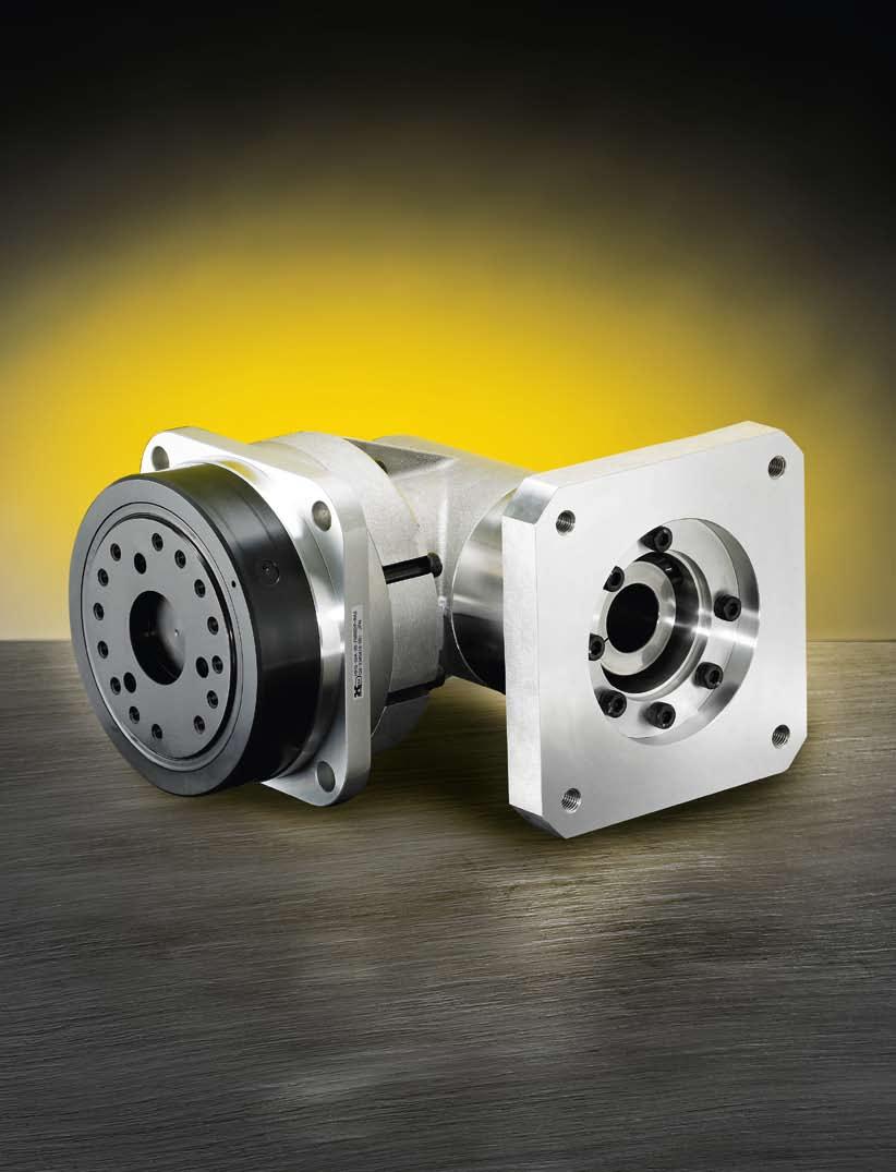
125 511
126 Projektierung mit Harmonic Drive Servoantrieben Engineering Data for Harmonic Drive Servo Actuators Wir freuen uns, Ihnen in diesem Kapitel ausführliche Informationen zu unseren Produkten präsentieren zu können. Die in unserem Katalog gebotenen Informationen sollen Ihnen bei der Auswahl Ihres Servoantriebs und den Aufgaben der Maschinenkonstruktion helfen. Wir sind davon überzeugt, dass der Umfang und die Qualität der hier dargestellten Daten denen anderer Servoantriebs-Hersteller genauso überlegen ist wie die Qualität unserer Produkte. Selbstverständlich stehen wir Ihnen zur Beantwortung Ihrer Fragen zur Verfügung. Eine Kontaktliste finden Sie auf der Rückseite dieses Katalogs oder auf unserer Website. Zögern Sie bitte nicht, uns anzusprechen. Die in diesem Katalog wiedergegebenen Werte basieren auf Messungen, die bei zahlreichen Tests während der Entwicklung unserer Produkte durchgeführt wurden. Zur Sicherung der Qualität unserer Produkte erfolgen laufend weitere Tests. Bitte beachten Sie, dass diese Werte, wie bei allen Messungen, von Produkt zu Produkt variieren können. Wenn diese Werte für eine spezifische Anwendung verwendet werden, sollte auch die Messgenauigkeit dieser Ergebnisse berücksichtigt werden. Soweit nicht anders angegeben, werden alle Tests, wie in diesem Katalog beschrieben, mit neuen Komponenten bei Normalluftdruck und -temperatur mit Standardschmierung durchgeführt. Die Ergebnisse können unter verschiedenen Bedingungen erheblich variieren. Für weitere Details kontaktieren Sie uns bitte. We are pleased to present detailed information about our products in this chapter. The information presented in our catalogue is designed to help you with your drive selection and machine design tasks. We consider the amount and quality of data presented here to be in excess of other drive system manufacturers just like the quality of our products. Of course we are available to answer any questions you may have. You will find a list of contacts on the back of this catalogue or on our website. Please feel free to contact us. The values in this catalogue are based on measurements made during numerous tests carried out during the development of our products. Further tests are continually being conducted to ensure the quality of these products is maintained. Please note that, as with all measurements, these values can vary from product to product. When using these values for a specific application, the measuring accuracy for these results should also be considered. When not otherwise stated, all tests are conducted with new components at standard air pressure and temperature with standard lubrication as described in this catalogue. Results may vary considerably under different conditions. For further details, please contact us. 512

127 Projektierung mit Harmonic Drive Servoantrieben Engineering Data for Harmonic Drive Servo Actuators 513
128 Projektierung mit Harmonic Drive Servoantrieben Engineering Data for Harmonic Drive Servo Actuators Antriebsauslegung Actuator Selection Procedure Flussdiagramm zur Systemauswahl Flowchart for Actuator Selection Bestimmung der Bewegungsart: Linearbewegung oder Rotationsbewegung Berechnung des Lastdrehmoments (T L ) und des Massenträgheitsmomentes der Last (J L ): Gleichung 515.4/515.6 Confirm the type of servo mechanism required: linear motion or rotary motion Calculate load torque (T L ) and moment of inertia (J L ): Equation 515.4/515.6 T 1 = T L + 2π 60. (J A + J L ). n 2 t 1 [Gleichung / Equation 514.1] Ermittlung des Drehzahlzyklus anhand der Belastungskurve Determine speed pattern from duty cycle T 2 = T L T 3 = T L. ( T 1 T L ) Vorauswahl des Servoantriebs anhand der Belastungsdaten Tentatively select the required actuator based upon load conditions T rms = T 1 2. t 1 + T 2 2. t 2 + T 3 2. t 3 t 1 + t 2 + t 3 + t p Berechnung des Beschleunigungsdrehmoments (T 1 ): Gleichung Calculate the required acceleration torque (T 1 ): Equation [Gleichung / Equation 514.2] Ist das benötigte Beschleunigungsdrehmoment geringer als das max. Abtriebsdrehmoment des Servoantriebs? Is the required acceleration torque less than max. output torque of the actuator? Nein No n av = n 2 2 n 2. t1 + n. 2 t 2 +. t 2 3 t 1 + t 2 + t 3 + t p [Gleichung / Equation 514.3] Ja Yes Bestimmung der auftretenden Drehmomente und Berechnung des Effektivdrehmomentes (T rms ): Gleichung Determine the torque pattern and calculate the effective torque (T rms ): Equation ED = t 1 + t 2 + t 3 t 1 + t 2 + t 3 + t p. 100 % [Gleichung / Equation 514.4] Berechnung der durchschnittlichen Drehzahl (nav): Gleichung Calculate average Speed (nav): Equation Berechnung der Einschaltdauer (ED): Gleichung Calculate duty factor (ED): Equation T rms und n av innerhalb der Continuous Duty Zone Ja Anforderungen erfüllt T rms and n av are inside the Continuous Duty Zone Yes Confirm final selection Nein No Nein No 514
129 Projektierung mit Harmonic Drive Servoantrieben Engineering Data for Harmonic Drive Servo Actuators Bedingungen für die Vorauswahl Pre Selection Conditions Tabelle / Table Last Load Bedingung Confirmation Tabellierter Wert Catalogue value Einheit Unit Max. Drehzahl der Last (n 2 ) Load max. rotation speed (n 2 ) n max Max. Drehzahl Max. output speed [min -1 ] [rpm] Massenträgheitsmoment der Last (J L ) Load moment of inertia (J L ) 3J A 1) Trägheitsmoment Moment of inertia [kgm 2 ] [kgm 2 ] 1) JL 3. J A wird für hochdynamische Einsatzfälle empfohlen (hohe Dynamik und Genauigkeit). 1) JL 3. J A is recommended for highly dynamic applications (high responsiveness and accuracy). Lineare Horizontalbewegung Linear Horizontal Motion Abb. / Fig Lastdrehmoment T L [Nm] Load torque T L [Nm] m [kg] Reibungskoeffizient µ Coefficient of friction µ Steigung/Pitch P [m] Kugelgewindespindel Trägheitsmoment J S [kgm 2 ] Ball screw moment of inertia J S [kgm 2 ] Wirkungsgrad η Efficiency η Rotationsbewegung Rotary Motion Abb. / Fig Reibungskoeffizient des Lagers µ Coefficient of friction of bearing µ T L [Nm] J L [kgm 2 ] m [kg] r [m] D [m] J L = J S + m ( P ) 2 2π [kgm 2 ] µ. m. P. g T = L 2π. η [Nm] [Gleichung / Equation 515.4] Abb. / Fig Drehzahldiagramm Speed pattern Drehzahl n [min -1 ] Speed n [rpm] n 2 Zeit /time t [s] J L = m 8. D 2 [kgm 2 ] T L = µ. m. g. r [Nm] g = 9,81 [m/s 2 ] [Gleichung / Equation 515.6] Drehmomentdiagramm Torque pattern Drehmoment T [Nm] Torque T [Nm] T 1 T2 T 3 t 1 t 2 t 3 t P Zeit / time t [s] Bemerkung t 1 = t 3 Note: t 1 = t 3 Betriebszyklus / Cycle t 0 515
130 Projektierung mit Harmonic Drive Servoantrieben Engineering Data for Harmonic Drive Servo Actuators Beispiel einer Antriebsauslegung Example of Actuator Selection Belastungsdaten Benötigt wird ein Servoantrieb, der bei einer horizontalen Drehachse eine Masse zyklisch positionieren muss. Load Conditions Assume servo mechanism is used to cyclically position a mass with a horizontal axis of rotation. Tabelle / Table Drehzahl der Last Load rotation speed Lastdrehmoment (z. B. Reibung) Load torque (e. g. friction) Trägheitsmoment der Last Load inertia Zykluszeiten Speed pattern Beschleunigen; Bremsen Acceleration; Deceleration Fahren mit Arbeitsdrehzahl Operate with rated speed Stillstand Stand still Gesamtzykluszeit Total cycle time Bemerkung: Die Berechnungswerte für die Auslegung müssen auf den Abtrieb des Servoantriebes bezogen werden. n 2 = [min -1 /rpm] T L = 5 [Nm] J L = 1,3 [kgm 2 ] t 1 = t 3 = 0,1 [s] t 2 = 0,1 [s] t p = 1 [s] t O = 1,3 [s] Please note: Each characteristic value should be converted to the value at the output shaft of the actuator. Abb. / Fig Drehzahldiagramm Speed pattern Drehzahl n [min -1 ] Speed n [rpm] n 2 = min -1 Zeit / time t [s] Drehmomentdiagramm Torque pattern Drehmoment T [Nm] Torque T [Nm] Bemerkung t 1 = t 3 Note t 1 = t 3 T 1 T 2 T 3 t 1 =0,1 t 2 =0,1 t 3 =0,1 t P =1 t 0 = 1,3 Zeit / time t [s] Antriebsdaten FHA-25C-50-L Actuator Data FHA-25C-50-L Tabelle / Table Max. Drehmoment Max. torque Max. Drehzahl Max. output speed Massenträgheitsmoment Moment of inertia T max = 151 [Nm] n max = 90 [min -1 /rpm] J A = 0,86 [kgm 2 ] 516
131 Projektierung mit Harmonic Drive Servoantrieben Engineering Data for Harmonic Drive Servo Actuators Antriebsauswahl Actuator Selection Vorauswahl eines Antriebes anhand der Belastungsdaten: FHA-25C-50 erfüllt die Bedingungen für die Vorauswahl (siehe Leistungsdaten) Tentatively select a required actuator based upon load conditions. FHA-25C-50 meets the tentative selection requirements from catalogue value (see rating table) Berechnung der Einschaltdauer Calculation of the duty factor n 2 = min -1 < n max = 90 min -1 J L = 1,3 kgm 2 < 3J = 2,58 kgm 2 ED = 0,1 + 0,1 + 0,1 100% 1,3 ED = 23 % Berechnung des Beschleunigungsdrehmomentes (T 1 ) Calculate required acceleration torque (T 1 ) T 1 = 5 + 2π (1,3 + 0,86) = 93 Nm 60 0,1 T rms = 35 Nm n av = 6 min -1 Nein No Ist das benötigte Beschleunigungsmoment geringer als das max. Abtriebsdrehmoment des Servoantriebs? T 1 = 95 Nm < T max = 151 Nm Confirm: Is the required acceleration torque less than the maximum output torque of the actuator? Prüfen anhand der Leistungscharakteristik T rms und n av innerhalb der Continuous Duty Zone Check according to the performance characteristics T rms and n av are inside the continuous duty zone Ja Berechnung des Effektivdrehmomentes (T rms) Yes Calculate effective torque (T rms) Anforderungen erfüllt Confirm final selection T 1 T 2 T 3 = 95 Nm = T L = 5 Nm = T L - (T 1 - T L ) = - 85 Nm , ,1 + (-85) 2 0,1 T rms = 1,3 = 35 Nm FHA-25C-50-L Abb. / Fig Berechnung der durchschnittlichen Drehzahl n av = Calculation of the average speed 0,1 + 0,1 + 0, ,3 n av = 6 min -1 Drehmoment / Torque [Nm] Intermittierender Betrieb Intermittent Duty Dauerbetrieb Continuous Duty Drehzahl [min -1 ] / Speed [rpm] min -1 = ^ rpm ED = 1 min. Wir übernehmen gerne Ihre Getriebeauslegung in unserem Haus. Bitte kontaktieren Sie unsere Anwendungsberater. We will be pleased to make a gear calculation and selection on your behalf. Please contact our application engineers. 517
132 Projektierung mit Harmonic Drive Servoantrieben Engineering Data for Harmonic Drive Servo Actuators Adaption an Servoregler Adaption of Servo Controllers Überlastschutz Zum Schutz der Servoantriebe vor unzulässigen Temperaturen sind in die Motorwicklungen Temperatursensoren integriert. Overload Protection For the protection of the servo actuator from inadmissible temperatures, temperature sensors are integrated into the motor winding. Tabelle / Table Antriebstyp Actuator type Temperatursensor Temperature sensor FHA-C-L/CHA/CHM PTC 116-K C FHA-C-H/CHA/CHM FFA-H/FPA-H KTY FFA-L/FPA-L/FPA-11A-H PTC 111-K13-1 C LynxDrive KTY PTC 116-K C TorkDrive 2 x KTY x PTC (130 C) Technische Daten PTC Technical Data PTC PTC-Kaltleiter sind spezielle keramische Widerstände. Wegen ihres sehr hohen positiven Temperaturkoeffizienten bei Nennansprechtemperatur (T Nat ) sind sie als Wicklungsschutz hervorragend geeignet. Im Bereich der Nennan sprechtemperatur steigt bei kleinsten Temperaturerhöhungen der Widerstand sehr steil an. The PTC sensor is a special ceramic resistor. Because of their very high positive temperature coefficients at nominal operating temperature (T Nat ) they are suitable for motor winding protection. Within the range of the nominal operating temperature the resistance rises very steeply at smallest changes of temperature. Abb. / Fig Kennlinie / Diagram PTC 00 Widerstand / Resistance [Ω] T NAT -5 T NAT T NAT +5 Temperatur / Temperature [ºC] 518
133 Projektierung mit Harmonic Drive Servoantrieben Engineering Data for Harmonic Drive Servo Actuators Technische Daten KTY Technical Data KTY Der KTY-Fühler dient der Temperaturmessung und Überwachung der Motorwicklung. Der Vorteil des KTY-Sensors liegt in der analogen Temperaturerfassung. Somit ist es möglich, nicht nur die Motorwicklung sondern auch das Getriebefett vor unzulässigen Temperaturen zu schützen. The KTY sensor serves for the temperature measurement and monitoring of the motor winding. The advantage of the KTY sensor is the analogue temperature measurement. It is therefore possible to protect the actuator winding and the actuator grease against inadmissible temperatures. Abb. / Fig Kennlinie / Diagram KTY Widerstand / Resistance [Ω] Temperatur / Temperature [ºC] Für die Harmonic Drive Servoantriebe werden nachfolgende Grenzwerte festgelegt: For the Harmonic Drive servo actuators the following values are fixed: Tabelle / Table FHA/CHA FFA/FPA/CHM/LynxDrive /TorkDrive Temperatur Temperature Widerstand Resistance Warnung Warning Abschaltung Shutdown Warnung Warning Abschaltung Shutdown 80 C ± 5 % 90 C ± 5 % 120 C ± 5 % 1 C ± 5 % 882 Ω ± 3 % 9 Ω ± 3 % 1127 Ω ± 3 % 1262 Ω ± 3 % 519
134 Projektierung mit Harmonic Drive Servoantrieben Engineering Data for Harmonic Drive Servo Actuators Überlastdauer Overload Duration Ist der Schutz der Antriebe mit Hilfe der Temperatursensoren nicht möglich, so muss das verwendete Regelgerät den Antrieb vor Überlastung schützen. Nachfolgende Abbildung zeigt abhängig von der Überlast die Zeitdauer bis zur Abschaltung. Der Überlastfaktor beschreibt das Verhältnis zwischen aktuellem Effektivstrom und Stillstandsstrom. If the protection of the actuator winding is not possible with the temperature sensor, then the servo controller must protect the actuator. The diagram shows the actuator overload characteristic in the case of excessive current. The overload value expresses the relation between actual effective current and continuous stall current. Abb. / Fig Überlastungscharakteristik / Overload characteristic 70,00 60,00 50,00 Zeit / Time [s],00 30,00 20,00 10,00 0,00 0,00 0,50 1,00 1,50 2,00 2,50 3,00 3,50 4,00 4,50 5,00 I / Is l s = Stillstandsstrom / Continuous stall current l = aktueller Effektivstrom / Actual effective current (l l max ) Drehrichtung Direction of Rotation Aufgrund des Wirkungsprinzips des eingebauten Harmonic Drive Getriebes wird die Drehrichtung umgekehrt. Das bedeutet, dass sich die interne, nicht sichtbare, Motorwelle im Uhrzeigersinn dreht, jedoch der Antrieb entgegen dem Uhrzeigersinn läuft. The principle of operation of the integrated Harmonic Drive Gear leads to a change in the direction of rotation. For example, if the motor shaft (not visible) is rotating in the clockwise direction, then the output will rotate in the counter clockwise direction. 520
135 Projektierung mit Harmonic Drive Servoantrieben Engineering Data for Harmonic Drive Servo Actuators Übersicht Servoregler Overview Servo Controllers Tabelle / Table Hersteller Manufacturer Typ Type Produkt Product Motorwicklung Motor winding Temperatursensor Temperature sensor Motorfeedback System Motor feedback system CHA / CHM FHA-C FFA / FPA LynxDrive TorkDrive FHA-mini 24 VDC-Zwischenkreis 24 VDC bus voltage 320 VDC-Zwischenkreis 320 VDC bus voltage 560 VDC-Zwischenkreis 560 VDC bus voltage PTC KTY Resolver 2-polig Resolver with 2 poles Inkrementeller Sinus/Cosinus Encoder Incremental sine/cosine encoder SIMODRIVE 611D SIMODRIVE 611U Siemens SINAMICS S120 MASTERDRIVES MC NUM AG MDLU º Danaher Motion Bosch Rexroth Beckhoff ESR Pollmeier S 0 S 0 º S 0 S 600 S 700 º IndraDrive º IndraDrive AX 2000 AX 5000 TrioDrive º MidiDrive MaxiDrive º º º º º º º º º Lenze Global Drive Parker Hannifin COMPAX Jenaer Antriebstechnik ECOVARIO º º º º º B+R ACOPOS Metronix ARS 2000 º º LTi-Drives ServoOne º º º º º º Harmonica ELMO Cornet Bassoon º º Control Techniques Unidrive º SEW MOVIDRIVE B º MOVIAXIS º HIPERFACE Encoder HIPERFACE encoder EnDat Encoder EnDat encoder Inkrementeller TTL Encoder Incremental TTL encoder = praktisch erprobt = theoretisch machbar = practically tested = theoretically possible Reglerausgangsspannung für PMA-Antriebe Controller Output Voltage for PMA Series Actuators Um die dargestellten Leistungsdaten und Kennlinien der Servoantriebe zu gewährleisten, ist eine minimale Reglerausgangsspannung bereitzustellen. Diese Spannung (U OUT ) berechnet sich wie folgt: A minimum controller output voltage is required in order to achieve the given rating data and performance curves for the servo actuators. This voltage (U OUT ) is calculated as follows: U OUT = n OUT. i. K E + I MAX. R [Gleichung / Equation 521.2] mit: U OUT = Reglerausgangsspannung [V DC ] n OUT = Getriebeausgangsdrehzahl [min -1 ] I = Getriebeuntersetzung K E = Spannungskonstante Motor [V/1000 min -1 ] I MAX = Maximaler Antriebstrom [A] R = Ankerwiderstand with: U OUT = Controller output voltage [V DC ] n OUT = Gear output speed [rpm] I = Gear ratio K E = Voltage constant motor [V/] I MAX = Maximum actuator current [A] R = Armature resistance 521
136 Projektierung mit Harmonic Drive Servoantrieben Engineering Data for Harmonic Drive Servo Actuators Berechnung Abtriebsdrehmoment Calculation of the Output Torque Aus der Stromaufnahme der CHA, PMA und LynxDrive Servoantriebsbaureihe kann entsprechend nachfolgender Vorgehensweise das abtriebsseitige Drehmoment berechnet werden. Der gemessene Strom enthält neben den drehmomentbildenden Anteilen auch den temperaturabhängigen und drehzahlabhängigen Leerlaufstrom. Zusätzlich sind auch die umrichterbedingten Verlust ströme enthalten. Bei der nachfolgenden Berechnung wird lediglich der drehmomentbildende Grundwellen strom betrachtet. Abb zeigt die Zusammenhänge zwischen Grundwellenstrom und abtriebsseitigem Drehmoment in Abhängigkeit von Aktuatordrehzahl und Aktuatortemperatur. The current dissipation of the CHA-, PMA- and LynxDrive-series servo actuators can be used to calculate the output torque at specific ambient and load conditions. The measured current consists of the torque producing part and also covers losses depending on temperature and actuator speed. Specific losses coming from pulse controlled servo controllers are included as well. The calculation given below is only based on the torque producing current (fundamental wave). Fig shows the relation between the fundamental wave and the output torque depending on actuator speed and actuator temperature. Abb. / Fig Der Leerlaufstrom bei 30 C Antriebstemperatur wird mittels Gleichung berechnet. The no load running current at 30 C actuator temperature can be calculated using equation I NLR (30 C) = I NLS + (K INL (30 C). n out ) [Gleichung / Equation 522.2] Das abtriebsseitige Drehmoment kann mit Gleichung bestimmt werden. The output torque can be calculated using equation T out = K T. (I - I NLR ) [Gleichung / Equation 522.3] T out = Abtriebsdrehmoment [Nm] T out = Output torque [Nm] I = Gemessener Strom (Grundwelle) [A] I = Measured current (Fundamental wave) [A] I NLS = Lastfreier Anlaufstrom [A] I NLS = No load starting current [A] I NLR = Leerlaufstrom [A] I NLR = No load running current [A] K INL = Leerlaufstromkonstante [A/min -1 ] K INL = No load current constant [A/rpm] n out = Aktuatordrehzahl [min -1 ] n out = Actuator speed [rpm] K T = Drehmomentkonstante (Abtrieb) [Nm/A] K T = Torque constant (at output) [Nm/A] 522

137 523
Produktbeschreibung CSD-2A Product Description CSD-2A
 Produktbeschreibung Product Description Einbausätze Baureihe Die Harmonic Drive Einbausätze der Baureihe zeichnen sich durch eine im Vergleich zur HFUC-2A Baureihe um fast 50 % verringerte Baulänge aus.
Produktbeschreibung HFUC-2A Product Description HFUC-2A
 Produktbeschreibung Product Description Einbausätze Baureihe Die Getriebeeinbausätze sind ein Ergebnis der konsequenten Weiterentwicklung der Harmonic Drive Präzisionsgetriebe. Gegenüber Standardgetrieben
Units HFUS-2UJ. Technische Daten. Technical Data. Abmessungen. Dimensions
 Units HFUS2UJ Technische Daten Technical Data Die HFUS2UJ Unit zeichnet sich neben dem leistungsfähigen KreuzrollenAbtriebslager insbesondere durch ihre Eingangswelle aus. Die in der Unit gelagerte Eingangswelle
Produktbeschreibung PMG Getriebeboxen Product Description PMG Gearboxes
 Produktbeschreibung Getriebeboxen Product Description Gearboxes Das Herz aller Getriebeboxen ist ein HDUC Einbausatz. Dieser wird in einem Gehäuse mit Abtriebswelle zu einer geschlossenen Getriebebox.
Engineering Data. Projektierung mit Harmonic Drive Getrieben. Engineering Data for Harmonic Drive Gears. Einbausätze / Component Sets
 Einbausätze / Component Sets Engineering Data Units / Units Getriebeboxen / Gearboxes Zahnprofil Tooth Profile Die in diesem Katalog beschriebenen Getriebeeinbausätze und Units werden mit der optimierten
Torques. T 1...T n [Nm] during the load phases t 1...t n [s] during the pause time t p [s] and Output Speeds. n 1...n n [rpm]
![Torques. T 1...T n [Nm] during the load phases t 1...t n [s] during the pause time t p [s] and Output Speeds. n 1...n n [rpm]](/thumbs/59/42939234.jpg "Torques. T 1...T n [Nm] during the load phases t 1...t n [s] during the pause time t p [s] and Output Speeds. n 1...n n [rpm]") Projektierung Projektierung mit Harmonic Planetengetrieben Auswahlschema Belastungsdaten am Abtrieb Output Data Selection Procedure n 2 Abb. / Fig. 450.1 Drehmomente T 1...T n [Nm] während der Belastungszeit
Projektierung Projektierung mit Harmonic Planetengetrieben Auswahlschema Belastungsdaten am Abtrieb Output Data Selection Procedure n 2 Abb. / Fig. 450.1 Drehmomente T 1...T n [Nm] während der Belastungszeit
Getriebeboxen HDUC-1U
 Getriebeboxen 200 Getriebeboxen Getriebeboxen HDUC-1U Inhalt: Getriebeboxen Contents: HDUC-1U Mini 202 HDUC-1U Getriebeboxen HDUC-1U Mini Produktbeschreibung Vorteile Bestellbezeichnungen Technische Daten
Produktbeschreibung Units HFUC-2UH Product Description HFUC-2UH Units
 Produktbeschreibung Units Product Description Units Abb. / Fig. 76.1 Units Baureihe Bei der Baureihe wurde der Einbausatz HFUC mit einem sehr kippsteifen Abtriebslager zu einer kompakten Getriebeeinheit
Antriebsdrehzahl/Input Speed Untersetzung i = Ratio R = Abtriebsdrehzahl/Output Speed 2) 3)
 3)") Projektierung Projektierung mit Harmonic Drive Getrieben An- und Abtriebsanordnungen Mit Harmonic Drive Getrieben sind unterschiedliche An- und Abtriebsanordnungen möglich. Diese Seite ist gültig für die
Projektierung Projektierung mit Harmonic Drive Getrieben An- und Abtriebsanordnungen Mit Harmonic Drive Getrieben sind unterschiedliche An- und Abtriebsanordnungen möglich. Diese Seite ist gültig für die
Technische Daten Technical data
 ESP-L Reihe ESP-L Series Technische Daten Technical data Typ [type] Untersetzung [ratio] ESP-L 60 ESP-L 75 ESP-L 100 1-stufig [1-stage] 3/4/5/7/10 Untersetzungen [ratio] 2-stufig [2-stage] 9/12/16/20/25/35/40/49/50/70/100
With output shaft, output housing & taper roller bearings. Getriebe mit Abtriebswelle, Kegelrollenlagerung und Gehäuse
 Fine Cyclo - F3C-A With output shaft, output housing & taper roller bearings Getriebe mit Abtriebswelle, Kegelrollenlagerung und Gehäuse Page Seite Type Designation 65 Typenbezeichnung Dimensions 66 Maße
Projektierungsanleitung Units CPU-M/H/S
 Projektierungsanleitung Units CPU-M/H/S QUICKLINK www.harmonicdrive.de/ Inhalt 1. Allgemeines... 03 1.1 Erläuterung der verwendeten Symbolik...04 1.2 Haftungsausschluss und Copyright...04 2. Sicherheits-
Projektierungsanleitung Units SHG-2UH/2SO/2SH
 Projektierungsanleitung Units SHG-2UH/2SO/2SH Weitere Informationen zu unseren Units, Getriebeboxen und Planetengetriebe finden Sie HIER! Kontaktieren Sie uns noch heute! Inhalt 1. Allgemeines... 03 1.1
Flanschversion mit output flange & Kegelrollenlagerung bearings
 Fine Cyclo - F2C-A Speed reducer with Flanschversion mit output flange & integrierter integrated taper roller Kegelrollenlagerung bearings Page Seite Type Designation 51 Typenbezeichnung Dimensions 52
4. TWINSPIN SELECTION PROCEDURE 4. TWINSPIN AUSWAHLVERFAHREN. 4.1 T, E, H, M series duty cycle. 4.1 Arbeitszyklus T, E, H, M Baureihe
 S E L E C T I O N P R O C E D U R E / A U S W A H L V E R F A H R E N 4. TWINSPIN SELECTION PROCEDURE 4. TWINSPIN AUSWAHLVERFAHREN 4.1 T, E, H, M series duty cycle T 1 T 2 T 3 maximum output torque at
Projektierungsanleitung Units HFUS-2UH/2SO/2SH
 Projektierungsanleitung Units HFUS-2UH/2SO/2SH QUICKLINK www.harmonicdrive.de/2060 Inhalt 1. Allgemeines... 03 1.1 Erläuterung der verwendeten Symbolik...04 1.2 Haftungsausschluss und Copyright...04 2.
Projektierungsanleitung Units SHG-2UH/2SO/2SH
 Projektierungsanleitung Units SHG-2UH/2SO/2SH Weitere Informationen zu unseren Units, Getriebeboxen und Planetengetriebe finden Sie HIER! Kontaktieren Sie uns noch heute! Inhalt 1. Allgemeines... 4 1.1
Projektierungsanleitung Units CobaltLine -CPM/CPH/CPS
 Projektierungsanleitung Units CobaltLine -CPM/CPH/CPS QUICKLINK www.harmonicdrive.de/ Inhalt 1. Allgemeines... 03 1.1 Erläuterung der verwendeten Symbolik...04 1.2 Haftungsausschluss und Copyright...04
PLE - line. technical data
 16 - Serie Serie line Z Lebensdauer lifetime h 30.000 96 1 Wirkungsgrad bei Volllast efficiency with full load % 94 2 90 3 Betriebstemperatur min. min. operating temp. -25 C Betriebstemperatur max. max.
Deceleration Technology. Rotary Dampers mit hohem Drehmoment WRD-H 2515 WRD-H 3015 WRD-H 4025 WRD-H
 Rotary Dampers mit hohem Drehmoment WRD-H 2515 WRD-H 3015 WRD-H 4025 WRD-H 6030 Deceleration Technology ONLINE CALCULATION AND 2D / 3D CAD DOWNLOAD M m L F Benefits Material: - Aluminium and steel Applications:
Deceleration Technology. Rotary Dampers with high-torque range WRD-H 7550 WRD-H 9565 WRD-H
 Rotary Dampers with high-torque range WRD-H 7550 WRD-H 9565 WRD-H 12070 Deceleration Technology ONLINE CALCULATION AND 2D / 3D CAD DOWNLOAD M m L F Benefits Material: - Aluminium and steel Applications:
Projektierungsanleitung Getriebeboxen CSF-Mini
 Projektierungsanleitung Getriebeboxen CSF-Mini QUICKLINK www.harmonicdrive.de/2100 1015786 08/2014 1 Inhalt 1. Allgemein...03 1.1 Erläuterung der verwendeten Symbolik...04 1.2 Haftungsausschluss und Copyright...04
Snap-in switch for switches PSE, MSM and MCS 30
 Product manual Snap-in switch for switches PSE, MSM and MCS 30 CONTENTS 1. PRODUCT DESCRIPTION 2. DATA AND DIMENSIONAL DRAWINGS 2.1. Technical Data 2.2. Dimensions of PSE with a Mounting Diameter 19 mm
Planetengetriebe P planetary gearboxes P
 lanetengetriebe Varianten planetary gearboxes variants lanetengetriebe planetary gearboxes Unsere lanetengetriebe der -Serie bieten Ihnen die bewährte TANDLER-Qualität zum günstigen reis. Das Ziel bei
Motion Control Drives
 Motion Control Drives EPG SERIES Servo Planetengetriebe Servo Planetary Gears 1 Übersicht Ausführungen/Design overview Getriebetyp/Gearbox Einbaulage/Mounting position Vollwelle mit Passfeder/ Solid shaft
Projektierungsanleitung Units CSD-2UF/2UH
 Projektierungsanleitung Units CSD-2UF/2UH QUICKLINK www.harmonicdrive.de/2070 Inhalt 1. Allgemeines... 03 1.1 Erläuterung der verwendeten Symbolik...04 1.2 Haftungsausschluss und Copyright...04 2. Sicherheits-
Deceleration Technology. Rotary Dampers with high-torque range WRD-H 0607 WRD-H 0805 WRD-H 1208 WRD-H 1610 WRD-H
 Rotary Dampers with high-torque range WRD-H 67 WRD-H 85 WRD-H 128 WRD-H 161 WRD-H 21 Deceleration Technology ONLINE CALCULATION AND 2D / 3D CAD DOWNLOAD M m L F Benefits Applications: - Mechanical and
Projektierungsanleitung Units HFUC-2UH
 Projektierungsanleitung Units HFUC-2UH QUICKLINK www.harmonicdrive.de/2050 Inhalt 1. Allgemeines... 04 1.1 Erläuterung der verwendeten Symbolik... 05 1.2 Haftungsausschluss und Copyright... 05 2. Sicherheits-
Projektierungsanleitung Einbausätze HFUC-2A
 Projektierungsanleitung Einbausätze HFUC-2A Weitere Informationen zu unseren Units, Getriebeboxen und Planetengetriebe finden Sie HIER! Kontaktieren Sie uns noch heute! Inhalt 1. Allgemeines... 04 1.1
Tube Analyzer LogViewer 2.3
 Tube Analyzer LogViewer 2.3 User Manual Stand: 25.9.2015 Seite 1 von 11 Name Company Date Designed by WKS 28.02.2013 1 st Checker 2 nd Checker Version history Version Author Changes Date 1.0 Created 19.06.2015
Projektierungsanleitung Einbausätze CSG-2A
 Projektierungsanleitung Einbausätze CSG-2A Weitere Informationen zu unseren Units, Getriebeboxen und Planetengetriebe finden Sie HIER! Kontaktieren Sie uns noch heute! Inhalt 1. Allgemeines... 03 1.1 Erläuterung
Evidence of Performance
 Air permeability, Watertightness, Resistance to wind load, Operating forces, Mechanical properties, Mechanical durability, Impact resistance Expert Statement No. 15-002226-PR01 (02) Product Designation
S T I R N R A D G E T R I E B E - M O T O R E N spur geared motors
 S T I R N R A D G E T R I E B E - M O T O R E N spur geared motors P E R F E K T E S Z U S A M M E N S P I E L H O H E F L E X I B I L I T Ä T Per fect interaction great flexibility Durch zahlreiche Anpassungsmöglichkeiten
Edelstahlgetriebe stainless steel gearboxes
 Edelstahlgetriebe stainless steel gearboxes Technische Daten /technical data N e u! N e w! Das besondere Kegelradgetriebe the unique bevel gearbox 1 Spiralkegelgetriebe in Edelstahlausführung VA Spiral
Kuhnke Technical Data. Contact Details
 Kuhnke Technical Data The following page(s) are extracted from multi-page Kuhnke product catalogues or CDROMs and any page number shown is relevant to the original document. The PDF sheets here may have
Integration of Simulation and Testing in Power Train Engineering Based on the Example of the Dual Mass Flywheel
 Integration of Simulation and Testing in Power Train Engineering Based on the Example of the Dual Mass Flywheel Institute of Machine Design and Automotive Engineering University of Karlsruhe, Germany o.
Word-CRM-Upload-Button. User manual
 Word-CRM-Upload-Button User manual Word-CRM-Upload for MS CRM 2011 Content 1. Preface... 3 2. Installation... 4 2.1. Requirements... 4 2.1.1. Clients... 4 2.2. Installation guidelines... 5 2.2.1. Client...
Oil / Air cooler ASA-TT 11 12V/24V DC Öl /Luftkühler ASA-TT 11 12V/24V DC
 Oil / Air cooler ASATT 11 12V/24V DC Öl /Luftkühler ASATT 11 12V/24V DC Pressure drop at 30 cst Druckabfall bei 30 cst Specific Cooling Performance Spezifische Kühlleistung TECHNICAL DATA TECHNISCHE DATEN
Anwendungsbereiche Areas of Application
 Kundenorientierte Lösungen Anwendungsbereiche Areas of Application Wir bieten das ideale System Die Kombinationen aus spielarmen Planetengetrieben mit hochgenauen Ritzeln und Zahnstangen sind höchst energieeffizient,
a) Name and draw three typical input signals used in control technique.
 Name and draw three typical input signals used in control technique.") 12 minutes Page 1 LAST NAME FIRST NAME MATRIKEL-NO. Problem 1 (2 points each) a) Name and draw three typical input signals used in control technique. b) What is a weight function? c) Define the eigen value
12 minutes Page 1 LAST NAME FIRST NAME MATRIKEL-NO. Problem 1 (2 points each) a) Name and draw three typical input signals used in control technique. b) What is a weight function? c) Define the eigen value
VGM. VGM information. HAMBURG SÜD VGM WEB PORTAL USER GUIDE June 2016
 Overview The Hamburg Süd VGM Web portal is an application that enables you to submit VGM information directly to Hamburg Süd via our e-portal Web page. You can choose to enter VGM information directly,
Newest Generation of the BS2 Corrosion/Warning and Measurement System
 Newest Generation of the BS2 Corrosion/Warning and Measurement System BS2 System Description: BS2 CorroDec 2G is a cable and energyless system module range for detecting corrosion, humidity and prevailing
Shock pulse measurement principle
 Shock pulse measurement principle a [m/s²] 4.0 3.5 3.0 Roller bearing signals in 36 khz range Natural sensor frequency = 36 khz 2.5 2.0 1.5 1.0 0.5 0.0-0.5-1.0-1.5-2.0-2.5-3.0-3.5-4.0 350 360 370 380 390
collective trade links pvt. ltd.
 Authorized Distributors collective trade links pvt. ltd. 17, Aryan Corporate Park, Nr. Thaltej Railway Crossing, Thaltej, Ahmedabad-380054. Phone: +91-79-26474700 50 Email: sales@collectivebearings.com
Projektierungsanleitung Einbausätze CPL-2A
 Projektierungsanleitung Einbausätze CPL-2A Weitere Informationen zu unseren Units, Getriebeboxen und Planetengetriebe finden Sie HIER! Kontaktieren Sie uns noch heute! Inhalt 1. Allgemeines... 04 1.1 Erläuterung
PLHE - Serie PLHE - line. Auf dem Weg zur Führungskraft. On the path to leadership
 24 Auf dem Weg zur Führungskraft NEUGART steht für innovative und rundum zukunftsweisende Lösungen in Sachen Getriebetechnologie. Aktuelles Beispiel: Das. Mit dieser Baureihe treffen wir erneut Ihre Erwartungen
Power supply Interference suppressed acc. to DIN EN /- 4, EN 55011, EN CI. B, power factor corrected Power factor BöSha LED driver
 Operating Instructions LED Mast Double Luminaire Callisto SC DB, incl. Inclination Adjustment, Single-Chip Technology (Please, read carefully before starting operation) Version: 16.01.2017 Model 369-M
Walter Buchmayr Ges.m.b.H.
 Seite 1/10 Chapter Description Page 1 Advantages 3 2 Performance description 4 3 Settings 5 4 Options 6 5 Technical data 7 6 Pictures 8 http://members.aon.at/buchmayrgmbh e-mail: walter.buchmayr.gmbh@aon.at
Dear Colleague, Please give us a call and let us know how we can assist you. We look forward to talking to you soon. Thank you.
 Dear Colleague, Thank you for visiting our website and downloading a product catalog from the R.M. Hoffman Company. We hope this information will be useful to you in solving the application you are working
Attention: Give your answers to problem 1 and problem 2 directly below the questions in the exam question sheet. ,and C = [ ].
![Attention: Give your answers to problem 1 and problem 2 directly below the questions in the exam question sheet. ,and C = [ ].](/thumbs/72/66904987.jpg "Attention: Give your answers to problem 1 and problem 2 directly below the questions in the exam question sheet. ,and C = [ ].") Page 1 LAST NAME FIRST NAME MATRIKEL-NO. Attention: Give your answers to problem 1 and problem 2 directly below the questions in the exam question sheet. Problem 1 (15 points) a) (1 point) A system description
Page 1 LAST NAME FIRST NAME MATRIKEL-NO. Attention: Give your answers to problem 1 and problem 2 directly below the questions in the exam question sheet. Problem 1 (15 points) a) (1 point) A system description
Projektierungsanleitung Einbausätze CSD-2A
 Projektierungsanleitung Einbausätze CSD-2A Weitere Informationen zu unseren Units, Getriebeboxen und Planetengetriebe finden Sie HIER! Kontaktieren Sie uns noch heute! 1 Inhalt 1. Allgemeines...03 1.1
VGM. VGM information. HAMBURG SÜD VGM WEB PORTAL - USER GUIDE June 2016
 Overview The Hamburg Süd VGM-Portal is an application which enables to submit VGM information directly to Hamburg Süd via our e-portal web page. You can choose to insert VGM information directly, or download
Bosch Rexroth - The Drive & Control Company
 Bosch Rexroth - The Drive & Control Company Alle Rechte bei Bosch Rexroth AG, auch für den Fall von Schutzrechtsanmeldungen. Jede Verfügungsbefugnis, wie Kopier- und Weitergaberecht, bei uns. 1 Case study
Hypex d.o.o. Alpska cesta 43, 4248 Lesce Slovenija Tel: +386 (0) Fax: +386 (0)
 Fax: +386 (0)") MAINTENANCE INSTRUCTIONS MTJ MRJ SERIES Hypex d.o.o. Alpska cesta, Lesce Slovenija Tel: + (0) 00 Fax: + (0) 0 www.unimotion.eu email: sales@unimotion.eu www.unimotion.eu MTJ MRJ Series OVERVIEW Used symbols
MAINTENANCE INSTRUCTIONS MTJ MRJ SERIES Hypex d.o.o. Alpska cesta, Lesce Slovenija Tel: + (0) 00 Fax: + (0) 0 www.unimotion.eu email: sales@unimotion.eu www.unimotion.eu MTJ MRJ Series OVERVIEW Used symbols
PLANETENGETRIEBE SPN-ECO (E2)
") www.spn-hopf.de PLANETENGETRIEBE SPN-ECO (E2) Planetary gearboxes SPN ECO (E2) Inhalt Content Planetengetriebe Planetary gearboxes SPN-Getriebe und Ritzel 3 SPN gearboxes and pinions SPN-ECO E2-Serie 4
www.spn-hopf.de PLANETENGETRIEBE SPN-ECO (E2) Planetary gearboxes SPN ECO (E2) Inhalt Content Planetengetriebe Planetary gearboxes SPN-Getriebe und Ritzel 3 SPN gearboxes and pinions SPN-ECO E2-Serie 4
Dreh- und Schwenktische Rotary Tables MORE VALUE FOR YOUR MACHINE.
 Dreh- und Schwenktische Rotary Tables MORE VALUE FOR YOUR MACHINE. KENNDATEN DREH- UND SCHWENKTISCHE ROTARY TABLES MAIN FEATURES SPEED LOAD RIGIDITY BRAKING POWER SAFETY BRAKE 0 HSD TECHNOLOGY up to ±2,5
Electrical testing of Bosch common rail Injectors
 Electrical testing of Bosch common rail Injectors Contents: 1. Adapter cable for Hybridtester FSA 050 (article number 0 684 010 050 / 1 687 023 571) 2. Electrical testing of Bosch common rail solenoid
Kuhnke Technical Data. Contact Details
 Kuhnke Technical Data The following page(s) are extracted from multi-page Kuhnke product catalogues or CDROMs and any page number shown is relevant to the original document. The PDF sheets here may have
PLN - Serie PLN - line. Der Allrounder. The all-rounder
 70 Der Allrounder Mit unserer Baureihe präsentieren wir ein perfektes Zusammenspiel aus Innovation, Effizienz und Wirtschaftlichkeit. Ob Drehmoment, Robustheit oder Präzision die attraktive Baureihe kann
Modularer Klemmrollenfreilauf GL...F2-D2(D3) Modular freewheel, roller type GL...F2-D2(D3)
 Modular freewheel, roller type GL...F2-D2(D3)") Modularer Klemmrollenfreilauf GL...F2-D2(D3) Modular freewheel, roller type GL...F2-D2(D3) Modell GL...F2-D2(D3) Die GL...F2-D2(D3) Serie ist gekennzeichnet durch Passungen zwischen dem Freilauf GL, dem
Modularer Klemmrollenfreilauf GL...F2-D2(D3) Modular freewheel, roller type GL...F2-D2(D3) Modell GL...F2-D2(D3) Die GL...F2-D2(D3) Serie ist gekennzeichnet durch Passungen zwischen dem Freilauf GL, dem
/ Technische Änderungen und drucktechnische Irrtümer vorbehalten.
 EZ-0225-V10 Air Bearing Spindle High accurancy air bearing spindle with direct drive. Equipped with an water-cooled synchronous motor (frequency at nominal speed 400 Hz), Power output 1880 W. Rotary encoder
Hülsenfreilauf / HF One-way Clutch Bearing
 BEARINGS A L L FOR B E YOUR A R IFUTURE N G S Hülsenfreilauf / HF One-way Clutch Bearing Zen Ball Bearings are manufactured to the highest quality for standard and non-standard applications. Our technical
Alle hier aufgelisteten Zahnstanden und Zahnräder haben einen Eingriffswinkel von 20 All the racks and pinions here listed have a pressure angle 20
 Zahnstangen und Ritzel s and Pinions UHPR Ultra High Verzahnungsqualität 4 Quality 4 Verzahnungsqualität 5 Quality 5 HPR High Verzahnungsqualität 6 Quality 6 Verzahnungsqualität 7 Quality 7 PR Verzahnungsqualität
STRATEGISCHES BETEILIGUNGSCONTROLLING BEI KOMMUNALEN UNTERNEHMEN DER FFENTLICHE ZWECK ALS RICHTSCHNUR FR EIN ZIELGERICHTETE
 BETEILIGUNGSCONTROLLING BEI KOMMUNALEN UNTERNEHMEN DER FFENTLICHE ZWECK ALS RICHTSCHNUR FR EIN ZIELGERICHTETE PDF-SBBKUDFZARFEZ41-APOM3 123 Page File Size 5,348 KB 3 Feb, 2002 TABLE OF CONTENT Introduction
Oscillating drives generate oscillating motions of the output shaft through an evenly formed rotary motion of the drive How does it function?
 Oscillating drives generate oscillating motions of the output shaft through an evenly formed rotary motion of the drive How does it function? the motion sequence in general: the input shaft rotates continuously,
ÜV Überlastschutz u. Verbindungssysteme GmbH
 ÜV Überlastschutz u. Verbindungssysteme GmbH Sudetenstraße 27 63853 ömlingen Phone: 06022/681700 Fax: 06022/681701 E-ail: info@uev-gmbh.de Internet: www.uev-gmbh.de 10-01-13 2 Product range Safety couplings
Titelbild1 ANSYS. Customer Portal LogIn
 Titelbild1 ANSYS Customer Portal LogIn 1 Neuanmeldung Neuanmeldung: Bitte Not yet a member anklicken Adressen-Check Adressdaten eintragen Customer No. ist hier bereits erforderlich HERE - Button Hier nochmal
2011 European HyperWorks Technology Conference
 2011 European HyperWorks Technology Conference Topology Optimization Methods applied to Automotive Transmission Housings 1 Agenda Introduction - Corporate Information - overview Topology Optimization for
ISLIKER MAGNETE AG - CH-8450
 DGV - Datenblätter DGV - Datasheets DGV DGV Übersicht overview Übersicht / Overview Typ Type Dimensionen Dimensions [mm] Drehwinkel Rotary angle [ ] Drehmoment Torque [Ncm] DGV-35.95 35/35 x 27.5 95 DGV-50.95
Electrical testing of Bosch common rail piezo injectors
 Applies to generation CRI 3: Bosch 10-position order number 0 445 115 = CRI 3-16 (CRI 3.0) 1600 bar 0 445 116 = CRI 3-18 (CRI 3.2) 1800 bar 0 445 117 = CRI 3-20 (CRI 3.3) 2000 bar Tools required: Hybrid
Finite Difference Method (FDM)
") Finite Difference Method (FDM) home/lehre/vl-mhs-1-e/folien/vorlesung/2a_fdm/cover_sheet.tex page 1 of 15. p.1/15 Table of contents 1. Problem 2. Governing Equation 3. Finite Difference-Approximation 4.
Finite Difference Method (FDM) home/lehre/vl-mhs-1-e/folien/vorlesung/2a_fdm/cover_sheet.tex page 1 of 15. p.1/15 Table of contents 1. Problem 2. Governing Equation 3. Finite Difference-Approximation 4.
Worm Gearboxes SG Schneckengetriebe SG
 Worm Gearboxes Schneckengetriebe Worm Gearboxes Schneckengetriebe The gearbox output shaft runs in selflubricating sintered bushes, as standard, there is a single output shaft on the left-hand side. Special
DIE NEUORGANISATION IM BEREICH DES SGB II AUSWIRKUNGEN AUF DIE ZUSAMMENARBEIT VON BUND LNDERN UND KOMMUNEN
 DIE NEUORGANISATION IM BEREICH DES SGB II AUSWIRKUNGEN AUF DIE ZUSAMMENARBEIT VON BUND LNDERN UND KOMMUNEN WWOM537-PDFDNIBDSIAADZVBLUK 106 Page File Size 4,077 KB 16 Feb, 2002 COPYRIGHT 2002, ALL RIGHT
Electrical tests on Bosch unit injectors
 Valid for Bosch unit injectors with order numbers 0 414 700 / 0 414 701 / 0 414 702 Parts Kit Magnet*: - F00H.N37.925 - F00H.N37.933 - F00H.N37.934 * For allocation to the 10-place Bosch order number,
FEM Isoparametric Concept
 FEM Isoparametric Concept home/lehre/vl-mhs--e/folien/vorlesung/4_fem_isopara/cover_sheet.tex page of 25. p./25 Table of contents. Interpolation Functions for the Finite Elements 2. Finite Element Types
TECHNISCHE DATEN TECHNICAL DATA
 SPANNBEREICHE CLAMPING RANGES Do not exceed the maximum allowable clamping ranges! **, **, **, 7** Harte, einteilige Backen Harte, geteilte Backen Hard -piece jaws d d d d d d d d d d 80-7 -0 8-7 - -9
SHD Baureihe kompakte Units SHD Series Compact Units
 SHD Baureihe kompakte Units SHD Series Compact Units Inhalt Content 3 Das Unternehmen The Company 4 Produktbeschreibung Product Description 5 Bestellbezeichnung und Leistungsdaten Ordering Code and Rating
PLANETENGETRIEBE PLANETARY GEARBOXES
 PLANETARY GEARBOXES GEMOTEG GmbH & Co. KG Walkenmühleweg 49 72379 Hechingen Web: www.gemoteg.de Mail: info@gemoteg.de Tel: 07471 / 93010-30 Prinzip Das Prinzip beruht auf einem einfachen Umlaufgetriebe.
Dynamic Hybrid Simulation
 Dynamic Hybrid Simulation Comparison of different approaches in HEV-modeling GT-SUITE Conference 12. September 2012, Frankfurt/Main Institut für Verbrennungsmotoren und Kraftfahrwesen Universität Stuttgart
J RG IMMENDORFF STANDORT F R KRITIK MALEREI UND INSPIRATION ERSCHEINT ZUR AUSSTELLUNG IM MUSEUM LU
 J RG IMMENDORFF STANDORT F R KRITIK MALEREI UND INSPIRATION ERSCHEINT ZUR AUSSTELLUNG IM MUSEUM LU 8 Feb, 2016 JRISFRKMUIEZAIMLAPOM-PDF33-0 File 4,455 KB 96 Page If you want to possess a one-stop search
Projektierungsanleitung Getriebeboxen PMG-M-S
 Projektierungsanleitung Getriebeboxen PMG-M-S QUICKLINK www.harmonicdrive.de/2090 Inhalt 1. Allgemeines... 03 1.1 Erläuterung der verwendeten Symbolik...04 1.2 Haftungsausschluss und Copyright...04 2.
Gleichstrom-Permanentmagnetmotor DC-Permanent Magnet Motor Type GfmO 5,5 2 Pol Leistung/ power: W
 Gleichstrom-Permanentmagnetmotor DC-Permanent Magnet Motor Type GfmO 5,5 2 Pol Leistung/ power: 10 125 W ESTAN Elektromaschinen und Steuerungsbau GmbH Burgunderstraße 6 D-79418 Schliengen (Germany) 1 Tel:
ATEX-Check list. Compiled by: Date: Signature: Acceptable practice at the determination of flash point: Closed cup according to ISO 2719
 Fire and explosion hazard ATEX 137 1999/92/EG und ATEX 95 2014/34/EU Danger assessment and determination of explosion protection zone for the test space as well as the installation site ATEX-Check list
Electrical testing of Bosch common rail solenoid valve (MV) injectors
 injectors") Applies to MV injector, generation: -CRI 1.0 / 2.0 / 2.1 / 2.2 -CRIN 1 / 2 / 3, with K oder AK plug Bosch 10-position order number Bosch-Bestellnummer CRI: 0 445 110 xxx Bosch-Bestellnummer CRIN: 0 445
Applies to MV injector, generation: -CRI 1.0 / 2.0 / 2.1 / 2.2 -CRIN 1 / 2 / 3, with K oder AK plug Bosch 10-position order number Bosch-Bestellnummer CRI: 0 445 110 xxx Bosch-Bestellnummer CRIN: 0 445
Leichtbaueinbausätze Baureihe CPL CPL Series Lightweight Component Sets
 Leichtbaueinbausätze Baureihe CPL CPL Series Lightweight Component Sets Inhalt Content 3 Das Unternehmen The Company 4 Produktbeschreibung Product Description 5 Bestellbezeichnungen und Technische Daten
Application Note. Import Jinx! Scenes into the DMX-Configurator
 Application Note Import Jinx! Scenes into the DMX-Configurator Import Jinx! Scenen into the DMX-Configurator 2 The Freeware Jinx! is an user friendly, well understandable software and furthermore equipped
Multicriterial Design Decision Making regarding interdependent Objectives in DfX
 Overview Multicriterial Design Decision Making regarding interdependent Objectives in DfX S. Bauer The Design Process Support of the Design Process with Design for X Visualization of Decision Problems
Dienstleistungsmanagement Übung 5
 Dienstleistungsmanagement Übung 5 Univ.-Prof. Dr.-Ing. Wolfgang Maass Chair in Economics Information and Service Systems (ISS) Saarland University, Saarbrücken, Germany Besprechung Übungsblatt 4 Slide
Right of alteration without prior notice reserved
 DC-Getriebemotor P26-M28x10 Planetengetriebe P26 mit M28x10 DC-Gearmotor P26-M28x10 Planetary Gearhead P26 with motor M28x10 Massbild Dimensions Änderungen vorbehalten Right of alteration without prior
Inhalt: Harmonic Planetengetriebe Content: Harmonic Planetary Gears
 Inhalt: Harmonic Planetengetriebe Content: Harmonic Planetary Gears HPG Produktbeschreibung HPG...128 Product Description HPG...128 Bestellbezeichnungen...130 Ordering Code...130 Technische Daten...131...131
Werkszeugnis Motor Typprüfung (2.2) (Prüfbescheinigung nach EN 10204)
 (Prüfbescheinigung nach EN 10204)") Werkszeugnis Motor Typprüfung (2.2) (Prüfbescheinigung nach EN 10204) Hubmotor *Motortyp Bemessung- / Betriebsverhalten IEC / EN 034-1 *Betriebsart S 3 - % Umrichterbetrieb Polzahl 4 *Wärmeklasse Th. Cl.
Werkszeugnis Motor Typprüfung (2.2) (Prüfbescheinigung nach EN 10204) Hubmotor *Motortyp Bemessung- / Betriebsverhalten IEC / EN 034-1 *Betriebsart S 3 - % Umrichterbetrieb Polzahl 4 *Wärmeklasse Th. Cl.
-0,02,2 E -0,12. p = max. Flächenpressung (N/mm2 )
") 10WR 10WR/I Dichtungen - Führungselemente -0,02,2 E -0,12 METRISCH 10WR METRIC ZOLL 10WR/I INCH D H9 M h8 d h8 Einsatzbereich see page 3 Maximale Flächenpressung bei 25 C :
10WR 10WR/I Dichtungen - Führungselemente -0,02,2 E -0,12 METRISCH 10WR METRIC ZOLL 10WR/I INCH D H9 M h8 d h8 Einsatzbereich see page 3 Maximale Flächenpressung bei 25 C :
Brand Label. Daimler Brand & Design Navigator
 Daimler Brand & Design Navigator 30. März 2016 Brand Label FUSO Financial uses the FUSO letters in combination with the word Financial in the font Daimler CS for name and label. Black lettering is set
Maße abhängig von der Ausführung. Siehe angegebene Seiten. / Dimensions depend on version. See refered pages. 1)
") EH 2 mit rotierender Trapezgewindespindel EH 2 with rotating trapezoidal-thread spindle Einstufige Getriebe One-stage gear units Zweistufige Getriebe Two-stage gear units X) Maße abhängig von der Ausführung.
EH 2 mit rotierender Trapezgewindespindel EH 2 with rotating trapezoidal-thread spindle Einstufige Getriebe One-stage gear units Zweistufige Getriebe Two-stage gear units X) Maße abhängig von der Ausführung.
Hochleistungskraftgetriebe
 Spiralkegelgetriebe Hochleistungskraftgetriebe spiral bevel gearboxes PowerMaster gearboxes Hochleistungskraftgetriebe PowerMaster gearboxes Im Vergleich zu unseren herkömmlichen Spiralkegelgetrieben können