Heizkreisverteiler HKV Heating circuit manifold HKV
|
|
|
- Britta Michel
- vor 8 Jahren
- Abrufe
Transkript
1 Heizkreisverteiler HKV Heating circuit manifold HKV COLLECTEUR HKV Collettore HKV Technische nformation & MontageANLETUNG Technical nformation & nstallation NSTRUCTONS nformation technique & NSTRUCTONS E Montage nformationi Techniche & STRUZON Montaggio ENERGE- UN SANTÄRSYSTEME ENERGY AN Sanitary-SYSTEMS Systèmes énergétiques et sanitaires SSTEM ENERGETC - SANTAR

2 nhaltsübersicht / Summary / Table des matières / Sommario eutsch francais Beschreibung escription Technische aten onnées techniques Abmessungen imensions Montage nstallation Befüllung / ruckprotokoll Remplissage / Tests de pression urchflussmenge/ Heizkreis ébitmètre / Circuit Zubehör Accessoires Bitte beachten! Attention! Verweis auf andere Abschnitte in der Bedienungsanleitung. Référence à d autres sections du mode d emploi. Verweis auf andere Montageanleitungen. Référence à d autres modes d emploi. english taliano escription escrizione Technical data ati tecnici imensions imensioni nstallation Montaggio illing / Pressure test Riempimento / Test di pressione lowmeter / Circuit Portata / Circuito di riscaldamento Accessories Accessori Take note! Attenzione! Reference to other sections in this instruction. Note nelle altre sezioni di queste istruzioni. Reference to other installation instruction. Note nelle altre istruzioni di installazione. 2

3 Heizkreisverteiler HKV Technische nformation & MontageANLETUNG eutsch
4 Technische aten Beschreibung ie Roth Heizkreisverteiler bestehen aus korrosionsbeständigem Rohr und sind für den Einsatz in lächen-heiz- und Kühlsystemen ausgelegt. Vorlauf und Rücklauf sind schallentkoppelt auf Verteilerhaltern vormontiert. Technische aten HKV Universal HKV mit A Material Messing Anzahl Heizkreise 2 12 Mittenabstand 54 mm Anschluss Systemrohre Anschluss VL / RL Max. ruck ¾" Eurokonus 1" AG flachdichtend 6 bar Max. Temperatur 70 C Anschlussgewinde Ventil M 30 1,5 Ventilhub 3 mm Max. urchfluss / Heizkreis 4 l/min Einstellung urchflussmenge Mit Regulierverschraubung gemäß iagramm, Seite 9 Mit einstellbarem Ventil, ablesbar im Schauglas, A maximal geöffnet 4

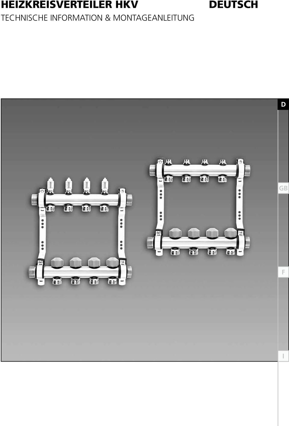
5 Abmessungen Abmessungen mit A universal 1 2 Vorlauf (montiert mit urchflussanzeigen oder Regulierverschraubung und Anschlussnippeln) Rücklauf (montiert mit Ventileinsatz und Anschlussnippeln) 3 Regulierverschraubung 4 urchflussanzeige (A) 5 Anschlussnippel 6 Anschlussnippel A 7 Bauschutzkappe 8 Ventileinsatz für Stellantrieb 9 Verteilerhalter 10 Stellantrieb (nicht im Lieferumfang enthalten) Größe L (mm) Mit Endstücken
 Größe 2 3 4 5 6 7 8 9 10 11 12 L (mm) 189 243 297 351 405 459 513 567 621 675 729 Mit Endstücken 249 303 357 411 465 519")
6 Montage Lieferumfang HKV mit Vorlauf und Rücklauf auf Verteilerhaltern mit integrierter Schallentkopplung vormontiert. Verteilerendstücke (Befüllen, Entlüften, Absperren) beigelegt. rucksachen beigelegt. Regulierverschraubung urchfluss und Ventil maximal geöffnet. Montage m Aufputz/Unterputz Verteilerschrank Wandmontage (Schallentkopplung bauseits) Schrankbreite Anzahl Heizkreise (Größe) HKV mm mm mm mm V mm mm mm mm mm Anschluss Vorlauf und Rücklauf Anschließen von Vorlauf und Rücklauf Anschließen der Heizkreise mit Klemmverschraubung oder Pressverschraubung ¾" Eurokonus Klemmverschraubung Ø 11, 14, 16, 17, 20 Pressverschraubung Ø 14, 16, 17, 20 6

7 Befüllen / ruckprotokoll Befüllung 1 Bauschutzkappe lösen, A oder Regulierverschraubung öffnen 2 Befüllen (Heizkreis für Heizkreis) über den Vorlauf 3 Bauschutzkappe wieder aufsetzen und Ventil schließen Alle weiteren Heizkreise genauso befüllen. 4 nach dem Befüllen aller Heizkreise die Kugelhähne am Endstück schließen ruckprotokoll ruckprotokoll ruckprobe: auer vor und während der Estrichverlegung Prüfdruck min 6 bar oder 2 Betriebsdruck 7

8 urchflussmenge / Heizkreis hkv mit urchflussanzeige ie urchflussanzeige dient nur zur Absperrung der Heizkreise. 2 1 Bauschutzkappe am 1. Heizkreis entfernen 2 A ganz öffnen 3 urchfluss gemäß Auslegung am Ventil einstellen Alle weiteren Heizkreise genauso einstellen. 4 stellantriebe gemäß Montageanleitung montieren und anschließen ruckverlust HKV 1" mit A 1 bis 12 Anschlüsse p [mbar] [l/min] 8

9 urchflussmenge / Heizkreis Alle Regulierverschraubungen und Ventile müssen geschlossen sein. hkv mit Regulierverschraubung 1 Bauschutzkappe am 1. Heizkreis entfernen 2 m5 Schraube der Regulierverschraubung lösen 3 mit M4 Schlüssel den urchfluss an der Regulierverschraubung gemäß Auslegung oder iagramm einstellen 4 mit M5 Schlüssel die Einstellung an der Regulierverschraubung sichern 5 1 Alle weiteren Heizkreise genauso einstellen. 5 stellantriebe gemäß Montageanleitung montieren und anschließen ruckverlust Regulierverschraubung Umdrehungen von geschlossen bis maximal geöffnet [l/min] p [mbar] 9

10 Zubehör Zubehör Klemmverschraubungen Ø 11, 14, 16, 17, 20 Pressverschraubungen Ø 14, 16, 17, 20 Kugelhahn 1" Blindkappe ¾" Wärmemengenzähler-Set senkrecht Wärmemengenzähler-Einbauset waagerecht estwertregelsets, Regelstation Verteilerschränke: Größe 0,,,, auf Putz V Stellantrieb 230 V, 24 V 10

11 Heating circuit manifold HKV Technical nformation & nstallation nstructions English

12 Technical data escription The Roth manifold consists of corrosion-resistant pipe and is designed for the use in surface embedded heating and cooling systems. Supply and return are mounted on sound-insulated brackets. Technical data HKV Universal HKV with flowmeter Material Brass Number of circuits 2 12 istance between pipes 54 mm Connection of systempipes Connection VL / RL Max. pressure ¾" Eurocone 1" (male) flatsealed 6 bar Max. temperature 70 C Connection actuating valve M 30 1,5 Valve lift Max. flow / circuit 3 mm 4 l/min Adjustment of the flow Adjustable screw fittings according to diagram, Page 17 Adjustable valve in the return, flow indicators in the supply max. open 12
 flatsealed 6 bar Max. temperature 70 C Connection actuating valve M 30 1,5 Valve lift Max.")
13 imensions imensions with flowmeter universal 1 2 Supply (mounted with flowmeters or adjustable screw fittings and pipe-connecting fittings) Return (mounted with valve and pipe connecting fittings) 3 Adjustable screw fitting 4 lowmeter (A) 5 Pipe connecting fitting 6 Pipe connecting nipple A 7 Protecting cap 8 Valve for actuating drive 9 Manifold bracket 10 Actuating drive (to be ordered separately) Size L (mm) With endpieces
 Size 2 3 4 5 6 7 8 9 10 11 12 L (mm) 189 243 297 351 405 459 513 567 621 675 729 With endpieces 249 303 357 411 465 519 573")
14 nstallation Scope of delivery Manifold supply and return mounted on brackets end pieces for filling manual ventilation, draining with ball valves and instruction manual and identifying labels for rooms and circuits adjustable screw fitting flowmeter and valve maximum opened. nstallation n in-wall or on-wall cabinet irectly on the wall (sound protection not included) Cabinet width Number of circuits (Size) mm mm mm mm V mm mm mm mm mm Connection of the heating and cooling circuits Connection of main supply and return 1" (male) flat sealed Connection of the heating/cooling circuits with compression fittings or press connections ¾" euro cone Compression fittings Ø 11, 14, 16, 17, 20 Press connection Ø 14, 16, 17, 20 14

15 illing / Pressure test illing 1 remove protection cap, open flowmeter A or adjustable screw fitting 2 fill always via supply (circuit by circuit) 3 close protection cap Repeat step 1 to 3 for all circuits. 4 after filling all the circuits, close the ball valves of the end pieces Pressure test Pressure test Leakage test: pressure test before and while bringing in the screed Test pressure min 6 bar or 2 operating pressure 15

16 lowmeter / Circuit Manifold HKV with flowmeter A The flowmeter is only used for shutting the circuits! 2 1 remove the protection cap from the 1st circuit s valve 2 Open the flowmeter completely 3 Adjust the flow according to the calculation on the valve Repeat step 1 to 3 for each circuit install and connect the actuating drives according to the manual 3 loss of pressure manifold HKV with flowmeter 1 to 12 circuits p [mbar] [l/min] 16

17 lowmeter / Circuit All adjustable screw fittings and valves must be closed! Manifold HKV with adjustable screw fittings 1 remove the protection cap from the 1st circuit s valve 2 isconnect M5 screw 5 3 adjust the flow with M4 allen key according to the calculation or diagram 1 4 fix the adjustment with M5 allen key Repeat step 1 to 4 for each circuit. 5 install and connect the actuators according to the manual loss of pressure of adjustable screw fitting Turns from closed to maximum open [l/min] p [mbar] 17

18 Accessories Accessories Compression fittings Ø 11, 14, 16, 17, 20 Press connections Ø 14, 16, 17, 20 Ballvalve 1" Screw cap ¾" Heat meter WMZ vertical Heat meter WMZ horizontal ix-value control sets, control station Cabinet: imension 0,,,, surface mounting V Actuator 230 V, 24 V 18

19 COLLECTEUR HKV nformation Technique & nstructions de Montage rancais

20 onnées techniques escription Les distributeurs de circuit de chauffage se composent de tubes résistants à la corrosion, et conviennent parfaitement aux systèmes de chauffage et rafraîchissement au sol. L aller et le retour sont pré-montés sur des supports isolés phoniquement. onnées techniques Collecteur HKV Universel Collecteur HKV équipé d un débitmètre Matériaux Laiton Nombre de circuits de chauffage 2 12 istance entre les tubes 54 mm Raccordement des tubes Eurocônes ¾" Raccordement VL / RL Pression max. iche mâle 1" isolée 6 bars Température max. 70 C Soupape à fixer M 30 1,5 Levée de soupape 3 mm lux max. / circuit 4 l/min Réglage du flux A l aide de la vis de réglage, selon le schéma, page 25 Avec l aide de la soupape réglable, visible au niveau de la jauge, indicateurs de flux ouverts au max. 20

21 imensions imensions avec débitmètre universel 1 2 Aller (équipées d indicateurs de débit ou vis de réglage et systèmes de raccordement pour tubes) Retour (équipée de supports pour valves et tubes) 3 Vis de réglage 4 ébitmètre (A) 5 Support de connexion pour tube 6 Support de connexion pour tube A 7 Bouchon de protection 8 Valve pour le servomoteur 9 Support pour le distributeur 10 Servomoteur (non fourni) Taille L (mm) Avec les extrémités
22 nstallation Pièces livrées Système de collecteur HKV avec aller / retour sur supports, équipé de dispositif d isolation phonique intégré, embouts de distribution (remplissage, vidage, arrêt). mprimés. Vis de réglage du débit et soupape ouverte au maximum. nstallation Système mural/encastré Montage au mur (protection phonique non fournie) Coffret largeur Nombre de circuits de chauffage (Taille) mm mm mm mm V mm mm mm mm mm Connexion aux circuits de chauffage et refroidissement Connexion au chauffage et refroidissement Raccordement des circuits de chauffage à l aide de raccords à compression ou raccords à sertir Eurocône ¾" Raccords à compression Ø 11, 14, 16, 17, 20 Raccords à sertir Ø 14, 16, 17, 20 22
23 Remplissage / Test de pression Remplissage 1 éfaire le bouchon de protection, ouvrir le débitmètre ou la vis de réglage 2 remplir (circuit de chauffage) à l aller 3 remettre le bouchon de protection Répéter les étapes 1 à 3 pour tous les autres circuits. 4 après le remplissage des circuits de chauffage, fermer les robinets au niveau des extrémités Test de pression Test de pression Test de pression: avant et pendant les travaux de chape Pression de 6 bars min. ou 2 pression opérationnelle 23
24 ébitmètre / Circuit Système HKV avec débitmètre Le débitmètre ne sert qu à fermer le circuit de chauffage. 2 1 retirer le bouchon de protection du circuit de chauffage 1 2 Ouvrir entièrement le débitmètre 3 Ajuster le flux selon le calcul sur la valve Répéter les étapes 1 à 3 pour chaque circuit installer et raccorder les servomoteurs comme indiqué sur le manuel. 3 Perte de pression Collecteur HKV 1" avec débitmètre 1 à 12 circuits p [mbar] [l/min] 24
25 ébitmètre / Circuit Toutes les vis de réglage et soupapes doivent être fermées. Système HKV avec vis de réglage 1 retirer le bouchon de protection du premier circuit de chauffage 2 évisser la vis M ajuster le niveau de flux avec la clef M4 selon les calculs indiqués sur le schéma 4 a l aide de la clef M5, resserrer la vis de réglage Répéter les étapes 1 à 4 pour chaque circuit. 5 installer et raccorder les servomoteurs selon le manuel Vis de réglage Perte de pression Tourner la vis pour qu elle passe de la position fermée à entièrement ouverte [l/min] p [mbar] 25
26 Accessoires Accessoires Raccords à compression Ø 11, 14, 16, 17, 20 Raccords à sertir Ø 14, 16, 17, 20 Vanne à sphère 1" Bouchon de protection ¾" Kit-Compteur de chaleur vertical Kit-Compteur de chaleur horizontal Groupe hydrauliques, station de régulations Coffret: taille 0,,,, mural V Servomoteur 230 V, 24 V 26
27 Collettore HKV nformationi Techniche & struzioni di Montaggio taliano
28 ati tecnici escrizione l collettore Roth è composto da un tubo resistente alla corrosione, che è rivestito per gli attacchi nell area del sistema di riscaldamento e raffrescamento. La mandata e il ritorno sono pre-montati ed isolati contro il rumore. ati tecnici HKV Universale HKV con A Materiale Ottone Numero di circuiti 2 12 istanza tra i tubi Attacchi del sistema Attacco VL / RL Pressione massima 54 mm ¾" Eurokono 1" AG M 6 bar Temperatura massima 70 C Connessione valvola M 30 1,5 Corsa valvola 3 mm Max. flusso / circuito 4 l/min mpostazione portata Con regolazione collegamento a vite. Seguire diagramma a pagina 33 Con valvola regolabile valvola di ritorno, A aperto nella fornitura al massimo 28
29 imensioni imensioni con A universale 1 Mandata (montata con segnalatore di portata o con regolatore ed attacco) 2 Ritorno (montato con valvola ed attacco) 3 Regolatore collegamento a vite 4 Segnalatore di portata (A) 5 Attacco raccordi 6 Attacco raccordi A 7 Cappuccio di protezione 8 Valvola per attuatori 9 Sostegno del collettore 10 Attuatore (non compreso) Tipo L (mm) Con tappo finale
30 Montaggio Volume di consegna L HKV è pre-montato con la mandata e il ritorno al sostegno del collettore, con ventilatore manuale e bloccaggi inclusi, sono presenti le istruzioni, e i collegamenti a vite per la regolazione del flusso e delle valvole sono aperti al massimo. Montaggio Cassetta collettore sopra/sotto intonaco Montaggio al muro (aggancio in loco) Cassette collettori largheza Numero di Circuiti (Tipo) mm mm mm mm V mm mm mm mm mm Attacco mandata e ritorno nstallazione della mandata e del ritorno nstallazione del circuito di riscaldamento con collegamento a vite a stringere o a stingere con bussola interna, ¾" Eurocono. Collegamento a vite a stringere Ø 11, 14, 16, 17, 20 Collegamento a vite a stringere con bussola interna Ø 14, 16, 17, 20 30
31 Riempimento / Test di pressione Riempimento 1 staccare il cappuccio di protezione, aprire o il A o il collegamento a vite del regolatore 2 riempire (circuito di riscaldamento) sulla man data 3 riposizionare il cappuccio di protezione e chiudere la valvola Riempire gli altri circuiti di riscaldamento allo stesso modo 4 opo aver riempito tutti i circuiti, chiudere i rubinetti a sfera e i terminali Test di pressione Test di pressione Prova di pressione: durata e drenaggio Test di pressione min 6 bar o 2 pressione d esercizio 31
32 Portata / Circuito di riscaldamento hkv con indicatore flusso di portata A L indicatore di flusso di portata serve solo per la chiusura del circuito di riscaldamento. 1 rimuovere il cappuccio di protezione al 1. circuito di riscaldamento 2 Aprire tutto il A 2 3 Regolare i flusso di portata alla valvola a seconda delle spiegazioni Regolare tutti gli altri allo stesso modo montare e chiudere gli attuatori a seconda delle istruzioni di montaggio 3 Perdita di pressione dell HKV 1" con A da 1 a 12 attacchi p [mbar] [l/min] 32
33 Portata / Circuito di riscaldamento Tutti i collegamenti a vite e le valvole devono essere chiusi. 1 rimuovere il cappuccio di protezione al 1. circuito di riscaldamento 2 svitare la vite M5 del collegamento a vite regolato hkv con collegamento a vite regolato con una chiave M4 regolare il flusso di portata del collegamento a vite secondo spiegazione o diagramma 4 con una chiave M5 assicurare l impostazione del collegamento Tutti gli altri circuiti devono essere regolati allo stesso modo. 5 montare e raccordare gli attuatori secondo le istruzioni di montaggio Perdita di pressione del collegamento a vite Girare da chiuso a massimo aperto [l/min] p [mbar] 33
34 Accessori Accessori Collegamento a vite a stringere Ø 11, 14, 16, 17, 20 Collegamento a vite a stringere con bussola interna Ø 14, 16, 17, 20 Rubinetto a sfera 1" Tappo cieco ¾" Contatore quantità di calore-kit verticale Contatore quantità di calore-kit orizzontale Kits di regolazione del valore fisso, stazione regulatrice Cassette collettori: dimensioni 0,,,, sopra V Attuatore 230 V, 24 V 34
35 Notizen / Notice / Notes / Note 35
36 ROTH WERKE GMBH Am Seerain autphetal (Germany) Telefon / Telefax / Hotline / service@roth-werke.de Technische Änderungen vorbehalten. / Specifications subject to change. / Sous réserve de modifications techniques. / Con riserva di modifiche tecniche.
Heizkreisverteiler HKV/ Heating circuit manifold HKV
 Heizkreisverteiler HKV/ Heating circuit manifold HKV MONTAGE- UND BEDIENUNGSANLEITUNG/ INSTALLATION INSTRUCTIONS ENERGIE- UND SANITÄRSYSTEME/ ENERGY AND PLUMBING-SYSTEMS Inhaltsübersicht/Summary Beschreibung/Technische
Armaturentechnik / Technique-robinetterie / Tecnica-rubinetteria. Robinet de réglage
 Regulierventil PN 16 Robinet de réglage PN 16 Valvola di regolazione PN 16 24022 Regulierventil PN 16, Regulierspindel mit Stellanzeige für Wasser bis 90 C mit Oberteil aus Rotguss Robinet de réglage PN
Ersatzteilliste Lista parti di ricambio Liste des pièces de rechange. Spare parts list (2017/08) db SLP 1/3-5/3 N
 db SLP 1/3-5/3 N") Ersatzteilliste Lista parti di ricambio Liste des pièces de rechange Spare parts list 6720814727 (2017/08) db SLP 1/3-5/3 N 16.08.2017 1 6720814727 16.08.2017 2 6720814727 16.08.2017 3 6720814727 Ersatzteilliste
Ersatzteilliste Lista parti di ricambio Liste des pièces de rechange Spare parts list 6720814727 (2017/08) db SLP 1/3-5/3 N 16.08.2017 1 6720814727 16.08.2017 2 6720814727 16.08.2017 3 6720814727 Ersatzteilliste
www.okw.com assembly instruction instruction de montage
 www.okw.com assembly instruction instruction de montage MONTAGEANLEITUNG datec-control M/L GEHÄUSE / ENCLOSURE / BOÎTIER Seite / page Best.-Nr./Part-No./Réf. M L DATEC-CONTROL M/L 4 A 90 78 107 A 90 79
2 IP X4 WLS/FL IP24. Montage-Anleitung Instructions de montage Assembling instructions. 225 cm. 60 cm 0
 WLS/FL IP Arbeiten an den elektrischen Anlagen dürfen nur von autorisierten Fachleuten nach den örtlichen Vorschriften ausgeführt werden. Für nicht fachgerechte Installation wird jegliche Haftung abgelehnt.
Zubehör Accessories Accessoires
 Seite Page Page 14/2 DA 14/4 Allgemeine Merkmale Drehantrieb General parameters Rotary drive unit Caractéristiques générales Servomoteur rotatif + 16 Zubehör Accessories Accessoires 14/0 Drehantrieb Rotary
IP X4 MOA/SL/FL IP44, CH IP24. Montage-Anleitung Instructions de montage Assembling instructions. 225 cm. 60 cm 0
 MOA/SL/FL IP44, CH IP4 Arbeiten an den elektrischen Anlagen dürfen nur von autorisierten Fachleuten nach den örtlichen Vorschriften ausgeführt werden. Für nicht fachgerechte Installation wird jegliche
L Montageanleitung Assembly instructions Instruction de montage EASYHOMESYSTEM TH-EHS. Änderungen vorbehalten Alle Rechte vorbehalten
 L-09-1-50 Montageanleitung Assembly instructions Instruction de montage EASYHOMESYSTEM TH-EHS Änderungen vorbehalten Alle Rechte vorbehalten Komponenten / Components / Composants / Componenti PGD Touch
BENCH das System für große Tischplatten BENCH the System for large desk tops BENCH - le systeme pour grands plateaux de table
 Gestellprogramm work station systems Programme de piétements BENCH das System für große Tischplatten BENCH the System for large desk tops BENCH - le systeme pour grands plateaux de table Gestellprogramm
Spare parts Accessories
 Seite Page Page 7/2 HZF 7/4 Allgemeine Merkmale Hydraulikzylinder mit äußerer Führung General parameters Hydraulic cylinder with external guide Caractéristiques générales Vérin hydraulique avec guidage
P-07. Pneumatically operated valves 3/2-way, G 1/4, 1580 Nl/min (1.606 Cv) Technical data for series
 Technical data for series") 3/2-way, G 1/4, Technical data for series -310-311 -312-320 -320-Q -322-322-Q Design and function Pneumatically operated spool valve. The valve switches upon pressurization of the pilot port (10 or 12).
3/2-way, G 1/4, Technical data for series -310-311 -312-320 -320-Q -322-322-Q Design and function Pneumatically operated spool valve. The valve switches upon pressurization of the pilot port (10 or 12).
Montageanleitung / Mounting instruction / Manuel de montage. D: Abmessung bis zur Klemme. Mat. Nr Typennummer
 Typennummer RFI Filter I0FAE1xxX100XxxxxS Filter Typ 1~ RFI Filter I0FAE1xxB100XxxxxS 3~ RFI Filter I0FAE1xxF100XxxxxS Technische Daten Typ E137B E175B E175F 100L... 100L... 100S... 100D... 100S... 100D...
Dati tecnici Technical data Technische daten. <Temperatura max. < Max. temperature < Max. temperatur
 Dati tecnici Technical data Technische daten
Zehnder ComfoWell 320
 Benefits All air treatment functions available: attenuator, fine filter, active carbon filter, manifold box Modular design Compact dimensions Easy to clean Components connected with locking slides for
Diagramm 1 2 A [mm] B [mm] C [mm] D [mm] Abmessungen
![Diagramm 1 2 A [mm] B [mm] C [mm] D [mm] Abmessungen](/thumbs/98/137025716.jpg "Diagramm 1 2 A [mm] B [mm] C [mm] D [mm] Abmessungen") Typennummer RFI Filter I0FAE3xxF100XxxxxS Filter Typ 3~ RFI Filter I0FAE3xxF100XxxxxS Technische Daten Typ E311F E322F E345F 100D... 100S... 100D 100D Bemessungsstrom [A] 29.00 / 22.6 55.00/46.00 100.00/86.00
Typennummer RFI Filter I0FAE3xxF100XxxxxS Filter Typ 3~ RFI Filter I0FAE3xxF100XxxxxS Technische Daten Typ E311F E322F E345F 100D... 100S... 100D 100D Bemessungsstrom [A] 29.00 / 22.6 55.00/46.00 100.00/86.00
1,2-1,8 TON TWIST 100 TWIST 100
 1,2-1,8 TWIST 100 L attuatore idraulico bi-direzionale Cangini permette di inclinare attrezzature o attacchi rapidi fino ad un angolazione di, facilitando le operazioni di scavo, anche in posizioni difficili
CONTROLLER RECEIVER REPEATER PAIRING SLIM CLIP
 ANLEITUNGEN // INSTRUCTIONS CONTROLLER RECEIVER REPEATER PAIRING SLIM CLIP BEDIENUNGSANLEITUNG // INSTRUCTION MANUAL MONTAGEANLEITUNG // ASSEMBLY INSTRUCTION MONTAGEANLEITUNG // ASSEMBLY INSTRUCTION KOPPLUNG
Filter Typ 3~ RFI Filter I0FAExxxF100DxxxxS
 Typennummer I0FAE3xxF100XxxxxS RFI Filter I0FAE4xxF100XxxxxS Filter Typ 3~ RFI Filter I0FAExxxF100DxxxxS Technische Daten Typ E355F E375F E411F 100D... 100D... 100D... Bemessungsstrom [A] 120.0 / 105.0
PBV1. Caratteristiche tecniche. Technical data. Technische Merkmale. Caracteristiques techniques ISO B ACCIAIO STEEL STAHL ACIER. Norme: ISO B
 PBV1 102 ISO B ACCIAIO STEEL STAHL ACIER Caratteristiche tecniche I Nominal size Max working pressure Rated flow Max flow rate Min burst pressure DNP BG ISO mm MPa l/min l/min MPa MPa MPa cc 04 0 5 4,2
ISTRUZIONI PER COLLEGAMENTO ECU MERCEDES TEMIC ACTROS ATEGO UNIMOG ECONIC ecc.
 ISTRUZIONI PER COLLEGAMENTO ECU MERCEDES TEMIC ACTROS ATEGO UNIMOG ECONIC ecc. ISTRUCTIONS FOR THE ECU MERCEDES TEMIC ACTROS ATEGO UNIMOG ecc. CONNECTION FG Technology 1/11 Smontare la Ecu dal camion,
in2itiv Montage- und Bedienungsanleitung Mounting- and operating instructions in2aqua GmbH
 1 in2itiv - und Bedienungsanleitung - and operating instructions instructions de montage et d utilisation Instructiones de montaje y de uso 9043 1 00 0 in2aqua GmbH Königstrasse 26 70173 Stuttgart, Germany
Edelstahlverteiler Stainless Steel Manifolds
 Edelstahlverteiler Stainless Steel Manifolds 0/0 Kalcher e.u. - Technische vorbehalten Inhaltsverzeichnis Table of Contents Fußbodenverteiler Typ HKV D 6 mit Durchflussmengenmessern Underfloor-Heating
SERIE 33 RACCORDI OGIVA COMPRESSION FITTINGS RACCORDS OGIVE ANSCHLÜSSE MIT DICHTUNGSKEGEL
 SERIE 33 RACCORDI OGIVA COMPRESSION FITTINGS RACCORDS OGIVE ANSCHLÜSSE MIT DICHTUNGSKEGEL 2Raccorderia Fittings CARATTERISTICHE TECNICHE CAMPI DI IMPIEGO: Circuiti pneumatici, oleodinamici e idraulici.
Attenuator and Distribution System Zehnder ComfoWell 220
 Benefits All air treatment functions available: attenuator, fine filter, active carbon filter, manifold box Modular design Compact dimensions Easy to clean Components connected with sliding profiles for
Montageanleitung / Mounting instruction / Manuel de montage. D: Abmessung bis zur Klemme. Mat. Nr Typennummer
 Typennummer RFI Filter I0FAE3xxF100XxxxXS Filter Typ 3~ RFI Filter I0FAE3xxF100XxxxXS Technische Daten Typ E311F E318F E322F 100D... 100S... 100D... 100D0000S 100D0001S Bemessungsstrom [A] 29.00 / 22.6
PVV3. Caratteristiche tecniche. Technical data. Technische Merkmale. Caracteristiques techniques
 PVV3 180 Nominal size Max working pressure Rated flow Max flow rate Min burst pressure DNP BG ISO mm MPa l/min l/min MPa MPa MPa cc 06 1 6.3 5 45 12 17 190 270 250 0,8 10 2 10 8,5 40 23 46 130 150 180
Blindabdeckung Blanking cover Obturateur
 Berührungsschutzabdeckung Contact hazard protection cover Plastron de protection contre les contacts 9674.900 9674.920 9674.960 9674.980 Blindabdeckung Blanking cover Obturateur 9674.905 Montage- und Bedienungsanleitung
Austausch Saugschlauch am CUBE-Dieseltank
 Austausch Saugschlauch am CUBE-Dieseltank GB Exchange of suction hose of CUBE diesel tank 137.0109.301 / 06.14 / Rn CEMO GmbH In den Backenländern 5 D-71384 Weinstadt Tel. +49 7151 9636-0 Fax +49 7151
Dati tecnici regolatori-filtri-lubrificatori-gruppi FRL
 Dati tecnici regolatori-filtri-lubrificatori-gruppi FRL Regulators-filters-lubricators-FRL units technical data Technischen Daten der Regolatore di pressione con relieving Campo di regolazione: 0-12 bar,
Montageanleitung / Mounting instruction / Manuel de montage. D: Abmessung bis zur Klemme. Mat. Nr Typennummer
 Typennummer RFI Filter I0FAE3xxF100XxxxxS Filter Typ 3~ RFI Filter I0FAE3xxF100XxxxxS Technische Daten Typ E330F E337F E345F 100D 100D 100D Bemessungsstrom [A] 55.00/45.70 69.00/57.00 100.00/86.00 Ableitstrom
Zehnder ComfoWell 220
 Benefits All air treatment functions available: attenuator, fine filter, active carbon filter, manifold box Modular design Compact dimensions Easy to clean Components connected with sliding profiles for
Heizkreisverteiler HKV QuickFix. Collecteur HKV QuickFix. Collettore HKV QuickFix.
 Montageanleitung nstructions de montage struzioni per il montaggio. Heizkreisverteiler HKV Quickix. Collecteur HKV Quickix. Collettore HKV Quickix. nhalt Sommaire Contenuto Montageanleitung ROTEX Heizkreisverteiler
mobilcom-debitel SmartHome Schnell-Start-Anleitung Quick Start Guide
 mobilcom-debitel SmartHome Schnell-Start-Anleitung Quick Start Guide 1. Cube anschließen 1. Connect Cube n Schließen Sie den Cube an die Stromversorgung an. n Legen Sie die Batterien polungsrichtig in
Connecting bend 90 connecting bend parts that serve as a connection between the hydraulic separator and the compact manifold.
 Technical data sheet MultiFlow Expert Components of the MultiFlow Expert - hydraulic separator - connecting bends - multiple compact manifolds [D] Manufacturer certification Description MultiFlow Expert
SHIMMER mensole e consolle
 SHIMMER mensole e consolle DESIGN PATRICIA URQUIOLA Istruzioni di montaggio ed utilizzo Assembling and use instruction SHIMMER mensole e consolle DESIGN PATRICIA URQUIOLA SHI05/SHI06 Accessori / Tools
ISTRUZIONI DI MONTAGGIO
 UMBRA RIMORCHI ltd. Via C. Pizzoni 37/39, 06132 Perugia - Italy Tel. +39 075 5280260 Fax +39 075 5287033 www.umbrarimorchi.it umbrarimorchi@umbrarimorchi.it ISTRUZIONI DI MONTAGGIO FITTING INSTRUCTIONS
Attenuator and Distribution System Zehnder ComfoWell 320
 Attenuator and Distribution System Zehnder ComfoWell 32 Benefits All air treatment functions available: attenuator, fine filter, active carbon filter, manifold box Modular design Compact dimensions Easy
PENTOLE DI COTTURA BOILING PANS MARMITES KOCHKESSEL
 IT Modelli cilindrici da 100 o 150 litri con riscaldamento diretto o indiretto Vasca di cottura con fondo in AISI 316 Struttura portante in acciaio inox e rivestimenti esterni in con finiture Scotch Brite
Kurzanleitung Ersatzgerät Guide succinct de l appareil de remplacement Breve guida all dispositivo di sostituzione
 Kurzanleitung Ersatzgerät Guide succinct de l appareil de remplacement Breve guida all dispositivo di sostituzione Das Ersatzgerät kann als zweites Gerät für die Nutzung des E-Bankings eingesetzt werden
Dati tecnici dei dosatori di flusso in polimero Plastic flow regulators technical data Technischen Daten der Drosselrückschlagventil Kunststoff
 -G -B Dati tecnici dei dosatori di flusso in polimero Plastic flow regulators technical data Technischen Daten der Fluido Aria compressa (altri fluidi a richiesta) Fluid Compressed air (other fluids on
PLK4 ISO MASCHIO INNESTABILE IN PRESSIONE MALE CONNECTABLE UNDER PRESSURE STECKER UNTER DRUCK KUPPELBAR MALE ACCOUPLABLE SOUS PRESSION
 43 ISO 16028 MASCHIO INNESTABILE IN PRESSIONE MALE CONNECTABLE UNDER PRESSURE STECKER UNTER DRUCK KUPPELBAR MALE ACCOUPLABLE SOUS PRESSION Caratteristiche tecniche PLK4 I Nominal size Max working pressure
Description for the replacement of electronic controls for gas recovery
 Information on the replacement of the electronic control Description for the replacement of electronic controls for gas recovery Important information! The new electronic control for gas recovery with
OPERATING INSTRUCTIONS Test pump ZG 5.1. and ZG 5.2.
 Elektromotoren und Gerätebau Barleben GmbH OPERATING INSTRUCTIONS Test pump ZG 5.1. and ZG 5.2. Elektromotoren und Gerätebau Barleben GmbH 2 Inhaltsverzeichnis Page 1 Use 4 2 Design features 4 2.1 Test
AD 300 AD 520. Scarichi per doccia Shower drains Ablaufgarnitur für Duschwannen. Shower drain completely checkable Ø 90 mm shower plate Ø 120 mm plug
 Scarichi per doccia Shower drains Ablaufgarnitur für Duschwannen Piletta sifonata per piatto doccia, completamente ispezionabile. Foro piatto doccia Ø 90 mm Tappo Ø 120 mm Shower drain completely checkable
EBA 4370 / EBA 4470 EBA 4376 / EBA DUVsWO. M.-Nr
 EBA 4370 / EBA 4470 EBA 4376 / EBA 4476 DUVsWO M.-Nr. 06 560 560 EBA 4370 / EBA 4470 2 EBA 4376 / EBA 4476 3 EBA 4376 / EBA 4476 Achtung: EBA 4376 / EBA 4476 Ist der Frontausschnitt seitlich nicht bündig
Dati tecnici dei dosatori di flusso in polimero Plastic flow regulators technical data Technischen Daten der Drosselrückschlagventil Kunststoff
 -G Dati tecnici dei dosatori di flusso in polimero Plastic flow regulators technical data Technischen Daten der Fluido Aria compressa (altri fluidi a richiesta) Fluid Compressed air (other fluids on request)
Dati tecnici regolatori-filtri-lubrificatori-gruppi FRL
 Dati tecnici regolatori-filtri-lubrificatori-gruppi FRL Regulators-filters-lubricators-FRL units technical data Technischen Daten der Regolatore di pressione con relieving Campo di regolazione: 0-12 bar,
Technical Documentation and Operation Manual. Kühlgehäuse der Pyrometerserie Metis Cooling jacket for pyrometer series Metis (KG10-00)
") Beschreibung und Bedienungsanleitung Technical Documentation and Operation Manual Kühlgehäuse der Pyrometerserie Metis Cooling jacket for pyrometer series Metis (KG10-00) Inhalt S./P. 1. Beschreibung /
Beschreibung und Bedienungsanleitung Technical Documentation and Operation Manual Kühlgehäuse der Pyrometerserie Metis Cooling jacket for pyrometer series Metis (KG10-00) Inhalt S./P. 1. Beschreibung /
Überlaufrinne System Wiesbaden mit Ausklinkung für Mosaikbekleidung
 04/2012 System Wiesbaden 7.1.0 Beckenkopfausbildung/hochliegender Wasserspiegel Exécution de la tête du bassin/niveau d eau élevé Execution of the pool head/elevated water level Esecuzione del bordo/livello
DC01 MODE D EMPLOI INSTALLATION INSTRUCTIONS BEDIENUNGSANLEITUNG
 MODE D EMPLOI INSTALLATION INSTRUCTIONS BEDIENUNGSANLEITUNG ST_DC01_A_151218 DC01 FERME-PORTE AVEC BRAS COMPAS DOOR CLOSER WITH STANDARD SCISSOR ARM TÜRSCHLIEßER MIT SCHERENGESTÄNGE l x h x p L x W x D
CarMedia. Bedienungsanleitung Instruction manual. AC-Services Albert-Schweitzer-Str.4 68766 Hockenheim www.ac-services.eu info@ac-services.
 CarMedia Bedienungsanleitung Instruction manual AC-Services Albert-Schweitzer-Str.4 68766 Hockenheim www.ac-services.eu info@ac-services.eu DE Inhaltsverzeichnis 1. Allgemeine Hinweise... 3 2. CarMedia...
fir e / 8", 1/ 2" gas liquid G A S - K U G E L H A H N E
 ga-s-top 3 / ", / 2" fir e gas VALVOLE A SFERA PER GAS GAS BALL VALVES G A S - K U G E L H A H N E Catalogue 2007 - Rev.0 0/207 liquid 09 ga-s-top 3 / ", / 2" Rubinetti a sfera in ottone diritti e ad angolo
Rohrschieber mit Schließfeder Slide Valve spring loaded
 Rohrschieber mit Schließfeder Slide Valve spring loaded Rohrschieber als automatisches Entlüftungsventil Slide Valve as automatic air relief valve Type: RSF DN: 50 300 (2 12 ) PN: 16 160 (Class 150 900)
Serviceinformation Nr. 02/11
 Serviceinformation Nr. 02/11 vom: 06.10.2011 von: BAM 1. Software Navigator und Release Notes Auf unserer Homepage unter www.idm-energie.at/de/navigator-software.html steht ab sofort eine neue Version
STAFFE, BORCHIE E ANELLONI
 STAFFE, BORCHIE E ANELLONI STAFFE staffe borchie anelloni etriers cabochons anneaux brackets studs rings garras clavos anillas stützhalter beschläge ringe STAFFA VENTAGLIO 110 110 50 70 60 140 70 27 085/10
PLT4 ISO 16028/350 BAR VALVOLA PIANA FLAT FACE FLACHDICHTENDE CLAPET PLAT. Caratteristiche tecniche. Technical data. Technische Merkmale
 ISO 16028/350 BAR VALVOLA PIANA FLAT FACE FLACHDICHTENDE CLAPET PLAT 22 PLT4 Caratteristiche tecniche I Norma: ISO 16028 HTMA (DN13) Occlusione: faccia piana Aggancio: sfere radiali Materiale: acciaio
ISTRUZIONI DI MONTAGGIO
 UMBRA RIMORCHI ltd. Via C. Pizzoni 37/39, 06132 Perugia - Italy Tel. +39 075 5280260 Fax +39 075 5287033 www.umbrarimorchi.it umbrarimorchi@umbrarimorchi.it ISTRUZIONI DI MONTAGGIO FITTING INSTRUCTIONS
DE Gebrauchsanleitung / Montageanleitung 2 EN Instructions for use / assembly instructions 3. Talis E²
 DE Gebrauchsanleitung / Montageanleitung 2 EN Instructions for use / assembly instructions 3 Talis E² 31612009 31612019 31612029 Deutsch Sicherheitshinweise Bei der Montage müssen zur Vermeidung von Quetsch-
PPV3 PUSH PULL VALVOLA POPPET VENTIL CLAPET. Caratteristiche tecniche. Technical data. Technische Merkmale. Caracteristiques techniques
 PUSH PULL VALVOLA POPPET VENTIL CLAPET 104 PPV3 Caratteristiche tecniche I Norma: ISO 7241-1 A Ghiera: doppia azione Occlusione: valvola Aggancio: sfere radiali Materiale: acciaio Finitura: Zn-Fe (Cr III)
Honeywell AG Hardhofweg. D-74821 Mosbach MU1H-1220GE23 R1001
 BA 95 Einbau-Anleitung Installation Instructions Einbau Installation Einbaubeispiel Installation example Ablaufleitung vorsehen Install discharge pipework Durchflussrichtung beachten! Consider direction
Istruzioni di montaggio e regolazione Cab-R 3D. Fitting and adjustment instructions Cab-R 3D. Montage- und Verstellanleitung CAB-R 3D
 Istruzioni di montaggio e regolazione Cab-R 3D Fitting and adjustment instructions Cab-R 3D Montage- und Verstellanleitung CAB-R 3D Piano di fresatura anta e telaio per maschio incassato Milling plan for
MINF - Mini Freestanding / MINW - Mini Wall. Montagehandleiding / Instructions de montage Montagehinweis / Mounting instructions
 MI - Mini reestaning / MIW - Mini Wall Montagehanleiing / Instructions e montage Montagehinweis / Mounting instructions AMETIGE VOOR AASLUITIG MET JAGA THERMOSTAATVETIEL IMESIOS POUR RACCOREMET AVEC VAE
Montageanleitung / Installation instruction / Notice de montage / Istruzioni di montaggio
 Rücklauf-Return-Retour-Ritorno im. ¼ T [mm] 3 9 [inch] 3,7 3,70 T [mm] 37 3 [inch],,9 T [mm] [inch],, Je nach Ausführung befindet sich der Vorlaufstamm oben oder unten ue to different type the supply pipe
AP Aufputz-Montage Montage en applique Surface mounting
 PAL/LED IP44, CH IP4 AP Aufputz-Montage Montage en applique Surface mounting Arbeiten an den elektrischen Anlagen dürfen nur von autorisierten Fachleuten nach den örtlichen Vorschriften ausgeführt werden.
UWC 8801 / 8802 / 8803
 Wandbedieneinheit Wall Panel UWC 8801 / 8802 / 8803 Bedienungsanleitung User Manual BDA V130601DE UWC 8801 Wandbedieneinheit Anschluss Vor dem Anschluss ist der UMM 8800 unbedingt auszuschalten. Die Übertragung
Entwurf. preliminary
 KAPRi plus Erweiterungsset M12 KAPRi plus Extension Kit M12 KAPRi plus Kit d Extension M12 Bedienungsanleitung / User instructions / Instructions d installation 899366 KAPRi plus Erweiterungsset M12 /
Montageanleitung Installation Instructions Notice de Montage
 Montageanleitung Installation Instructions Notice de Montage R Reflexlichtschranke / Reflexlichttaster Retro-reflective sensor / Diffuse reflection sensor Système réflex / Système réflexion directe OE
PNEUMATISCHE PUMPEN PNEUMATIC PUMPS
 BVBA POMAC-LUB-SERVICES SPRL Korte Bruggestraat 28 B-8970 Poperinge Tel. 057/33 48 36 Fax 057/33 61 27 info@pomac.be internet: www.pomac.be EINLEITUNGSSCHMIERSYSTEM MIT VOLUMETRISCHEN DOSIERVENTILEN FÜR
CONNECTION DIAGRAM - LA36. English. Deutsch. Italiano
 CONNECTION DIAGRA - LA36 English Deutsch Italiano CONNECTION DIAGRA - LA36 LA36 ACTUATOR Actuator with Parallel Actuator 8 Actuator 7 Actuator 6 Actuator 5 Actuator 4 Actuator 3 Actuator 2 Actuator 1 WARDS
Attenuator and Distribution System Zehnder ComfoWell 520
 Attenuator and Distribution System Zehnder ComfoWell 520 Benefits All air treatment functions available: attenuator, fine filter, active carbon filter, manifold box Modular design Compact dimensions Easy
Beipackzettel Instruction leaflet
 Beipackzettel Instruction leaflet Montage an einen Wandarm Mounting to wall arm Pepperl+Fuchs GmbH Antoniusstr. 21 D-73249 Wernau Germany Tel.: +49(0) 621 776-3712 Fax: +49(0) 621 776-3729 www.pepperl-fuchs.com
NOTICE D EMPLOI Pompes d essai ZG 5.1. et ZG 5.2.
 Elektromotoren und Gerätebau Barleben GmbH NOTICE D EMPLOI Pompes d essai ZG 5.1. et ZG 5.2. Elektromotoren und Gerätebau Barleben GmbH 2 Sommaire page 1 Application 4 2 Conception 4 2.1 Pompe d essai
ALPHA ALPHA ALPHA ALPHA B / HE - 2. nach DIN 68 885. ALPHA B/HE 2 620 1270 mm. Gestellprogramm work station systems Programme de piétements
 Gestellprogramm work station systems Programme de piétements ALPHA ALPHA ALPHA ALPHA B / HE - 2 Sitz-Steh-Arbeitsplatz mit elektrischer Höhenverstellung Verstellbereich: 620 1270 mm wahlweise mit memory
 PATENT PENDING T4 9380198-8580198 - 8880198-2080198 INDICE / INDEX / INHALTSVERZEICHNIS Contenuto della scatola / Box contents / Verpackungsinhalt... 3 Informazioni tecniche / Technical information / Technische
2 IP X4 TAI/LED IP44, CH IP24. Montage-Anleitung Instructions de montage Assembling instructions. 225 cm. 60 cm 0
 Montage-Anleitung Instructions de montage Assembling instructions TAI/LED IP, CH IP Sensor-Schalter aussen unten rechts Interrupteur sensitif en bas à l'extérieur à droite Sensor switch outside right below
HYDRAULIK. Pumpen Motoren Regler Zylinder Ventile Zubehör
 BH GFlug-, Schiffsund Pumpen Motoren Regler Zylinder Ventile Zubehör HYDRAULIK-ZYLINDER HYDRAULIC CYLINDERS / VÉRIN HYDRAULIQUE Alle Zylinder sind komplett aus rostfreiem Edelstahl gefertigt. Sie sind
Küchenarmaturen. Seite. Seite Metris Select Page 8.2 Pagina. Talis Select S Page 8.3. Pagina. Seite Metris Page 8.3 Pagina. Seite
 Metris Select Page 8.2 Metris Page 8.3 Talis Select S Page 8.3 Talis S 2 Variarc Page 8.4 Talis S Page 8.5 Focus Page 8.7 Logis Page 8.7 Zubehör Accessoires Page 8.8 Accessori Metris Select Einhebel-Küchenmischer
1. Mise à jour de la version programme des cartes PCU-02 et PCU-03
 T Service Documentation Technicocommerciale Information Technique Rubrique H Chaudières murales gaz à condensation GMR 3000 Condens Nouvelle version de programme de la carte PCU-02, PCU-03 : F1.7 P5253
Schlösser und Zubehör
 Schlösser und Zubehör Bauer Systemtechnik GmbH Gewerbering 7, 84072 Au/Hallertau Tel.: +49 (0) 8752-865809-0, Fax: +49 (0) 8752-9599 info@bauer-tore.de Lieferzeit bei unseren Spezialkatalogen bitte anfragen!
Betriebsanleitung AC-4703
 28 mm 47 mm Dokumentenstückliste C105395.001 BNC- Stecker 1 BNC- Stecker 2 BNC- Stecker 3 BNC- Stecker 4 Betriebsanleitung Adapterkabel Abbildung 1) Adapterkabel Anwendung Das Adapterkabel wird benötigt,
Bruciatori policombustibile gasolio/gas Dual fuel Gas-Oil/Gas burners Brûleurs mixtes fioul/gaz Mehrstoffbrenner Heizöl/gas
 Istruzioni per installazione, uso e manutenzione Installation, use and maintenance instructions Instructions pour installation, utilisation et entretien Installations-, Bedienungs- und Wartungsanleitung
linea air AIR ZINCATO
 ZINCATO Tubi e gomiti zincati Galvanised sheet iron pipes and elbows Tubes et coudes en tôle galvanisée Rohre und Knie aus verzinktem Blech Galvanised Galvanisé Verzinkt linea air ZINCATO AIR TUBI galvanised
1 Allgemeine Information
 1 Allgemeine Information ACHTUNG! Der Betriebsdruck der Klasse 867 ist 6 bar. Sollte der Druck Ihrer Versorgungsleitung höher als 6 bar sein, muss der Druck an der Versorgungseinheit der Nähmaschine auf
H 2010 /... H 2020 /... Einzelnadelventil Single needle valve Obturateur singulaire
 H 10 /... H /... Einzelnadelventil Single needle valve Obturateur singulaire D / GB / F 0 / 1 HK Einbaufertige Einheit Ready to install unit Unité prêt au montage Besondere Merkmale Große Flexibilität
Umschaltventile Magnete
 Umschaltventile Magnete DFE1/6 estellnr. Typ 2-11-12 DFE1/618ES-W22-12VDC 2-11-13 DFE1/618ES-W22-24VDC 24--116 DFE1/618ES-Y22-12VDC 24--117 DFE1/618ES-Y22-24VDC 24--1 DFE1/618ES-W22-12VDC 24--12 DFE1/618ES-W22-24VDC
INSTALLAZIONE INSTALLATION MONTAGE EINBAU
 INSTALLAZIONE INSTALLATION MONTAGE EINBAU MANUTENZIONE SOFFIONI MySlim ISPEZIONABILI MAINTENANCE OF MySlim INSPECTABLE&SERVICEABLE SHOWER HEADS ENTRETIEN DES POMMES DE DOUCHE MySlim INSPECTABLES WARTUNG
2.3. Anbohrarmaturen und Zubehör Colliers de prise et accessoires 2.3.001. Anbohrarmaturen und Zubehör Mechanische Merkmale
 Register Registre Mechanische Merkmale Anbohrarmaturen, oben, seitlich PE-Schweissstutzen Adapter für ZAK-System Bohrloch-Dichthülsen Einbaugarnituren Anbohr-Werkzeuge Caractéristiques mécaniques Colliers
Einbausatz Hub montieren
 Einbausatz Hub montieren Die Hub-Halterung bietet Platz für zwei Hubs. Es können nur Hubs eingebaut werden, die über den Konfigurator bzw. Rack-Architekt bestellbar sind. Der Lieferumfang besteht im Grundausbau
TECHNICAL DATA SHEET. Drinking water unit TS-S1000 TS-S TS-S TS-S TS-S Basic unit. Hydraulic diagram
 THNIAL ATA SHT rinking water unit TS-S1000 TS-S1000-14 TS-S1000-20 TS-S1000-30 TS-S1000-40 asic unit Hydraulic diagram omestic hot water home rinking water from the line Heating flow, primary Heating return,
EN Instructions for use / assembly instructions 2 DE Gebrauchsanleitung / Montageanleitung 3
 EN Instructions for use / assembly instructions 2 DE Gebrauchsanleitung / Montageanleitung 3 Ecos 14080019 / 14080029 Ecos L 14081019 / 14081029 Novus 70 71020019 / 71020029 Novus 100 71030019 / 71030029
11 EN 81-70 Page 1 of 2 Standard: INTERPRETATION RELATED TO. Clause(s): 5.4.2.3
: 5.4.2.3") CEN RELATED TO 11 Page 1 of 2 Standard: Edition: 2003 Clause(s): 5.4.2.3 Valid from: 15/09/2010 Date of modification: Key-word(s): Car operating panel, Two entrance lift Replacing interpretation No.: QUESTION
CEN RELATED TO 11 Page 1 of 2 Standard: Edition: 2003 Clause(s): 5.4.2.3 Valid from: 15/09/2010 Date of modification: Key-word(s): Car operating panel, Two entrance lift Replacing interpretation No.: QUESTION
EMCO Installationsanleitung Installation instructions
 EMCO Installationsanleitung Installation instructions Installationsanleitung Installation instructions Digitalanzeige digital display C40, FB450 L, FB600 L, EM 14D/17D/20D Ausgabe Edition A 2009-12 Deutsch...2
DACHFENSTER-KASSETTEN-ROLLO Store enrouleur à coffre pour fenêtre de toit
 Montage- und Bedienungsanleitung Notice de montage et mode d emploi DACHFENSTER-KASSETTEN-ROLLO Store enrouleur à coffre pour fenêtre de toit 04- Bedienung: Bedienschiene Manipulation : Rail de tirage
CABLE TESTER. Manual DN-14003
 CABLE TESTER Manual DN-14003 Note: Please read and learn safety instructions before use or maintain the equipment This cable tester can t test any electrified product. 9V reduplicated battery is used in
Umschaltventile Magnet
 Umschaltventile Magnet DFE1/3 estellnr. Typ 2-11-1 DFE1/318ES-W22-12VDC 2-11-1 DFE1/318ES-W22-24VDC 24-2-116 DFE1/318ES-Y22-12VDC 24-2-117 DFE1/318ES-Y22-24VDC Weitere Umschaltventil Varianten auf nfrage
TACJET NOZZLE WATERJET-TECHNOLOGY
 Cross jet nozzles 1000 bar Kreuzstrahldüsen 1000 bar Buses jets croisés 1000 bar 03.060 Cross jet nozzles 1000 bar The cross jet enz golden jet nozzle (with brake jet) is applied for industrial cleaning
SOLAR THERMAL SYSTEMS / SISTEMA SOLARE TERMICO / SOLARANLAGEN / INSTALLATIONS SOLAIRES. Cod. UG18E033
 SOLAR THERMAL SYSTEMS / SISTEMA SOLARE TERMICO / SOLARANLAGEN / INSTALLATIONS SOLAIRES Cod. UG8E033 297 SOLAR THERMAL SYSTEMS / SISTEMA SOLARE TERMICO / SOLARANLAGEN / INSTALLATIONS SOLAIRES SOLAR THERMAL