SEITENKANALVERDICHTER, DRUCK- UND VAKUUMBETRIEB CL Serie und Typ TBT. SIDE CHANNEL BLOWERS AND EXHAUSTERS CL Series and TBT Type
|
|
|
- Steffen Grosse
- vor 6 Jahren
- Abrufe
Transkript


1 SEITENKANALVERDICHTER, DRUCK- UND VAKUUMBETRIEB CL Serie und Typ TBT SIDE CHANNEL BLOWERS AND EXHAUSTERS CL Series and TBT Type

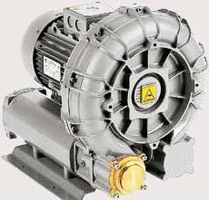
2 SEITENKANALVERDICHTER - CL Serie SIDE CHANNEL MACHINES - CL Series Arbeitsweise Seitenkanalverdichter erhöhen den Druck des angesaugten Gases mittels einer Serie von Verwirbelungen, die durch Zentrifugalkraft im peripheren Ringkanal erzeugt werden. Durch die Rotation des Laufrades wird das Gas in den einzelnen Kammern in eine Drehbewegung versetzt, während die dabei entstehende Zentrifugalkraft das Gas nach außen in den Seitenkanal drückt. Auf diese Weise entstehen spiralförmige Verwirbelungen. Während dieser Verwirbelungen wird das Gas wiederholt verdichtet, was den linearen Druckanstieg über die gesamte Länge des Seitenkanals zur Folge hat. Operating principle The side channel blower or exhauster increases the pressure of the aspirated gas by the creation, in the peripheral toroidal channel, of a series of vortexes caused by the centrifugal thrust of the impeller. While the impeller is rotating, the vanes force the gas forward and, because of the centrifugal thrust, outwards, producing a helical motion. During this motion, the gas is recompressed repeatedly with a consequent linear pressure increase along the length of the channel. Anwendungsgebiete und Vorteile Seitenkanalverdichter sind für all jene Applikationen geeignet, bei denen mehr Druck bzw. Vakuum benötigt wird als Zentrifugalgebläse leisten können. Im Vakuumbetrieb finden sie überall dort Anwendung, wo das benötigte Vakuum größer als das eines Gebläses und kleiner als das einer Vakuumpumpe ist. Die rotierenden Teile des Seitenkanalverdichters berühren das Gehäuse nicht. Da es während des Betriebes keine Reibungsverluste gibt, ist folglich auch keine Schmierung erforderlich. Der Verdichtungsvorgang erfolgt absolut ölfrei, eine Verunreinigung des Gases findet nicht statt. Weitere Vorteile: einfache Installation; geringer Schalldruckpegel; vibrationsfreier Betrieb und somit vollkommen dynamische Stabilität; keine Pulsation des Fördermediums; geringer Wartungsaufwand. Applications and advantages Side channel blowers are suitable for all those applications requiring considerably higher pressures than that which can be achieved using centrifugal fans. Side channel exhausters are used in all those applications requiring an operating vacuum higher than the one achievable by a fan, but not as high as to require the use of a vacuum pump. The rotating parts are not in contact with the casing. There is therefore no friction during operation and thus no internal lubrication is necessary. The gas moving through the machine therefore remains uncontaminated and completely oil-free. The other main advantages of using side channel machines are: easy installation; low noise level; no vibration and therefore complete dynamic stability; pulsation free discharge; minimal maintenance. Arbeitsbereich Range of duty [hpa = mbar] Druckdifferenz (Überdruck) Outlet pressure CL Seiten/pages 7 Druckbetrieb Blowers TBT Seiten/pages 6-7 [hpa = mbar] Druckdifferenz (Unterdruck) Inlet vacuum Vakuumbetrieb Exhausters CL Seiten/pages TBT Seiten/pages [m /h] Volumenstrom / Flow rate Volumenstrom / Flow rate [m /h]
3 Technische Eigenschaften und Konstruktion Gehäuse und Laufrad sind aus einer Aluminiumlegierung gefertigt. Die Standardausführung für Luft wird als sog. KOMPAKTE VERSION gefertigt. Der Elektromotor- Vorderflansch bildet eine Einheit mit der vorderen Gehäusehälfte des Verdichters und das dynamisch ausgewuchtete Laufrad ist direkt an der Motorwelle angeflanscht. Die 2-poligen, für den Dauerbetrieb ausgelegten Elektromotoren sind für alle im Katalog aufgeführten Leistungsbereiche als -Phasen- Version lieferbar; 1-Phasen-Version, 50 Hz, bis kw. Sie sind gemäß IEC Spezifizierungen mit folgenden Standardeigenschaften gefertigt: - für Maschinentypen ohne Endung HS und anderen als CL 1R und CL 2R: Schutzklasse: - IP 55 Isolationsklasse: - F für Motorleistung bis kw - H für Motorleistung kw und darüber Netzspannung: Netz Frequenz Motorleistung Netzspannung - Ph - Ph 50 Hz 50 Hz kw kw 20 VΔ / 00 V 00 VΔ / 690 V 1 - Ph 50 Hz kw 20 V - Ph - Ph 60 Hz 60 Hz,6 kw,8 kw 265 VΔ / 60 V 60 VΔ / 795 V Die zugelassene Spannungstoleranz bei 50 Hz beträgt ± 10%, gemäß IEC 6008 Norm. Sowohl bei 60 Hz als auch bei sondergefertigten Motoren und bei Sonderspannungen (50 und 60 Hz) beträgt die Spannungstoleranz ± 5%, gemäß IEC 600 Norm. - für Maschinentypen mit Endung HS : Schutzklasse: - IP5 Isolationsklasse: - F Netzspannung: Netz Frequenz Motorleistung Netzspannung - Ph - Ph 50 Hz 50 Hz kw kw ( ) 200~20 VΔ / 5~15 V 5~15 VΔ / 595~720 V 1 - Ph 1 - Ph 50 Hz 50 Hz 1,5 kw kw 10~127 V / 208~25 V 20~22 V - Ph - Ph 60 Hz 60 Hz,5 kw,6 kw ( ) 208~275 VΔ / 80~80 V 80~80 VΔ / 660~720 V ( ) mit Ausnahme von CL 60 HS /,6 kw dessen Motor, in Standardausführung, für folgende Netzspannung hergestellt ist: 50 Hz : 200~20 VΔ / 5~15 V 60 Hz : 208~275 VΔ / 80~80 V - für Maschinentypen CL 1R und CL 2R: Schutzklasse: - IP5 Isolationsklasse: - F Netzspannung: Netz Frequenz Motorleistung Netzspannung - Ph - Ph 50 Hz 50 Hz 0,7-1,6 - kw 7,5 kw 200~20 VΔ / 5~15 V 5~15 VΔ / 600~720 V 1 - Ph 50 Hz 0,7 kw 220~20 V - Ph 60 Hz 0,8-2,05-2,55 kw 220~275 VΔ / 80~80 V - Ph 60 Hz 8,6 kw 80~80 VΔ / 660~720 V Die Maschinen entsprechen den Anforderungen der Europäischen Richtlinien 2006/2 (Maschinen), 2006/95 (Niedervolt), 200/108 (Elektromagnetische Verträglichkeit) und den anzuwendenden Normen. Technical and constructional features Casings and impellers are made of aluminium alloy. The standard machines for air are manufactured in the so-called CLOSE COUPLED version; i.e. the front shield of the electric motor is also the machine motor-side casing half. The impeller, which is dynamically balanced, is fitted directly onto the motor shaft extension. The two-pole electric motors, designed for continuous operation, are available in three phase for all the powers shown in the catalogue and in single phase, at 50 Hz, up to 2.2 kw. They are manufactured according to IEC Specifications with the following standard features: - for machines without HS suffix and other than CL 1R and CL 2R: degree of protection: - IP 55 insulation class: line voltages: - F for powers up to kw - H for powers kw and above Main Frequency Motor power Line voltage - ph - ph 50 Hz 50 Hz kw kw 20 VΔ / 00 V 00 VΔ / 690 V 1 - ph 50 Hz kw 20 V - ph - ph 60 Hz 60 Hz,6 kw,8 kw 265 VΔ / 60 V 60 VΔ / 795 V For 50 Hz supply, the allowed voltage variation is ± 10% according to IEC 6008 Standard. For 60 Hz supply, as well as for motors specifically requested for any other voltage at 50 Hz or at 60 Hz, a ± 5% tolerance on supply voltage is allowed, in accordance with IEC 600 Standard. - for machines with HS suffix: degree of protection: - IP5 insulation class: - F line voltages: Main Frequency Motor power Line voltage - ph - ph 50 Hz 50 Hz kw kw ( ) 200~20 VΔ / 5~15 V 5~15 VΔ / 595~720 V 1 - ph 1 - ph 50 Hz 50 Hz 1,5 kw kw 10~127 V / 208~25 V 20~22 V - ph - ph 60 Hz 60 Hz,5 kw,6 kw ( ) 208~275 VΔ / 80~80 V 80~80 VΔ / 660~720 V ( ) with the exception of CL 60 HS /,6 kw whose motor, in the standard version, is manufactured for the line voltages: at 50 Hz : 200~20 VΔ / 5~15 V at 60 Hz : 208~275 VΔ / 80~80 V - for machines CL 1R and CL 2R: degree of protection: - IP5 insulation class: - F line voltages: Main Frequency Motor power Line voltage - ph - ph 50 Hz 50 Hz 0,7-1,6 - kw 7,5 kw 200~20 VΔ / 5~15 V 5~15 VΔ / 600~720 V 1 - ph 50 Hz 0,7 kw 220~20 V - ph - ph 60 Hz 60 Hz 0,8-2,05-2,55 kw 8,6 kw 220~275 VΔ / 80~80 V 80~80 VΔ / 660~720 V The machines meet the requirements of the European Directives 2006/2 (Machines), 2006/95 (Low Voltage), 200/108 (Electromagnetic Compatibility) and of the applicable harmonised Standards. Zubehör Eine breite Palette an Zubehörteilen für alle Maschinen ist lieferbar: Ansaugfilter für Druckbetrieb und Vakuumbetrieb - flexible Schlauchverbindungen - Rückschlagventile - Überdrucksicherheitsventile und Vakuumsicherheitsventile - Manometer und Vakuummeter - Umschaltventile - Schallschutzhauben. Accessories A complete range of accessories is available for all machines: cartridge type filters for blowers - in-line filters for exhausters - flexible hoses - non return valves - pressure relief valves for blowers - vacuum relief valves for exhausters - pressure and vacuum gauges - acoustic enclosures.
 für Zonen 1 und 2, 21 und 22 hergestellt.")
4 50 Hz Druckbetrieb 50Hz Motoren (2900 U/min) Blowers with 50 Hz motors (2900 rpm) Anmerkung / Note: Die meisten Seitenkanalverdichter für Luft wurden auch in Übereinstimmung mit der Europäische Richtlinie 9/9/EG (ATEX) für Zonen 1 und 2, 21 und 22 hergestellt. Most of the blower models for air are also manufactured in conformity to the requirements of the European Directive 9/9/EC (ATEX) for Zones 1 and 2, 21 and Volumenstrom-Druck Diagramm Flow rate-pressure diagram 20/21 5,5 2/21 7,5 0/21 6/21 7,5 9,2 2/21 9/ /1 Legende Key Maschinentyp Machine type Motorleistung [kw] Motor power [kw] /21 1/21 17/21 720HS 2R8 2R9 5,5 7, HS 10/21 20HS 28/1 7,5 5,5 0/1 6/1 7,5 9,2 /1 80-ZHS 5,5 5,5 7,5 60/1 TBT/M 9, /1 20 9,2 18, /1 15 1R9 8/1 7,5 18, /21 220HS 0,8 /01 0,7.6/01 0,25 20HS 0,22 7/21 1,1 7/01 0,75 0, 0,75 1R.5 0,7 0,55 10/01 1,1 0,55 1,1 0-Z HS 15/01 1,5 18/01 1,5 60HS 22/01 1,5 50HS 0,9 0,75 1,6 0HS 1,5 1,1 1,5 1,1 1,1 1R5.5 1,6 1,5, 7,5 5,5 5,5 5,5 9,2 7,5 7,5 7,5 5,5 7,5 5,5 9,2 5,5 5,5 5,5 12,5 15 9,2 18,5 8,5 7,5 16, ,5 9,2 5,5 7, Die Volumenströme beziehen sich auf Luft unter Bedingungen bei 20 C und 101 mbar abs. Flow rates refer to air at 20 C and 101 mbar abs. Volumenstrom Flow rate [m /h] [m /h] [hpa = mbar] [hpa = mbar] Druckdifferenz (Überdruck) Outlet pressure
5 50 Hz Druckbetrieb 50 Hz (2900 U/min) Blowers at 50 Hz (2900 rpm) Temperaturerhöhung [ C] - Temperature rise [ C] Druckdifferenz (Überdruck) [hpa = mbar] Outlet pressure CL 20 HS 1 CL 0-Z HS 27 CL.6/ CL / CL 7/ CL 1R CL 10/ CL 0 HS CL 15/ CL 50 HS CL 18/ CL 1R CL 60 HS CL 28/ CL 22/ CL / CL 0/ CL 80-Z HS CL 6/ Maschinentyp CL 60/ CL 72/ Blower CL 1R CL 8/ CL 98/ Type TBT/M CL / CL 7/ CL 220 HS CL 10/ CL 12/ CL 20 HS CL 1/ CL 17/ CL 520 HS CL 20/ CL 2/ CL 720 HS CL 0/ CL 6/ CL 2/ CL 2R CL 9/ CL 2R Toleranz: ± 5 C - Tolerance: ± 5 C Schalldruckpegel db(a) bei 1m Abstand Sound level db(a) at 1m Druckdifferenz (Überdruck) [hpa = mbar] Outlet pressure CL 20 HS 68 CL 0-Z HS 69 CL.6/ CL / CL 7/ CL 1R CL 10/ CL 0 HS CL 15/ CL 50 HS Maschinentyp CL 18/ CL 1R Blower CL 60 HS CL 28/ CL 22/ Type CL / CL 0/ CL 80-Z HS CL 6/ CL 60/ CL 72/ CL 1R CL 8/ CL 98/ TBT/M Der Schalldruckpegel wird nach dem Standard EN ISO 2151 in 1 Meter Abstand gemessen. Toleranz der Schalldruckpegel: ± 2 db(a) Schalldruckpegel db(a) bei 1m Abstand Sound level db(a) at 1m Druckdifferenz (Überdruck) [hpa = mbar] Outlet pressure CL / CL 7/ CL 220 HS CL 10/ CL 12/ CL 20 HS CL 1/ Maschinentyp CL 17/ CL 520 HS Blower CL 20/ CL 2/ Type CL 720 HS CL 0/ CL 6/ CL 2/ CL 2R CL 9/ CL 2R The noise level is intended as sound pressure level (SPL), measured in free field, in accordance with the Standard EN ISO Tolerance on sound level values: ± 2 db(a). 5
6 50 Hz Leistungsdaten Druckbetrieb 50Hz Motoren Blowers - performance with 50 Hz motors Druckdifferenz (Überdruck) hpa = mbar Outlet pressure Volumenstrom - Flow rate m /h m /h m /h m /h m /h m /h m /h m /h m /h m /h m /h m /h Motorleistung - Motor power kw kw kw kw kw kw kw kw kw kw kw Maschinentyp Blower Type CL 20 HS ,22 [ 0 m /h bei/at 70 mbar ] CL 0-Z HS 8 5 0, 9 0, 2 0, 9 0, [ 6 m /h bei/at 10 mbar ] CL.6/ , ,25 15,5 0,25 0,25 6 0,25 CL / ,7 1 0,7 2 0,7 18 0,7 0,7 0,7 CL 7/ ,55 5 0,55 0,55 5 0, , ,75 7 0,75 CL 1R ,7 68,5 0,7 5 0,7 7,5 0,7 22 0,7 CL 10/ , , , , ,1 50 1,1 0 1,1 0 1,1 CL 0 HS ,9 ( ) 10 0,9 ( ) 89 0,9 ( ) 7 0,9 ( ) 59 0,9 ( ) 1,1 0 1,1 CL 15/ ,1 15 1, , ,1 95 1,1 81 1,5 68 1,5 5 1,5 1 1,5 CL 50 HS , , ,5 1 1,5 6 1,5 99 1,5 82 1, CL 18/ , ,5 18 1, , CL 1R ,6 21 1,6 19 1, , ,6 17 1, CL 60 HS CL 28/ CL 22/ CL / , ,5 CL 0/ , , ,5 26 5,5 CL 80-Z HS , , ,5 22 5,5 CL 6/ ,5 75 5,5 56 5,5 8 5,5 20 7,5 0 7,5 CL 60/ ,5 88 5,5 6 5,5 0 7,5 16 7,5 92 7,5 68 9,2 CL 72/ ,5 59 5,5 56 7,5 52 7, ,5 71 9,2 1 9,2 CL 1R ,5 92 8, ,5 88 8, , ,5 7 12, , , , ,5 CL 8/ , ,5 91 5, ,5 88 7, , ,2 72 9, CL 98/ , , , , , TBT/M ,5 CL / ,55 2 0,55 8 0,55 0,55 0 0, , , ,75 1 0, ,75 6 0,75 CL 7/ ,1 65 1,1 60 1,1 5 1,1 9 1,1 1,1 8 1,1 1,1 28 1,1 22 1,1 17 1,1 CL 220 HS ,8 65 0,8 58 0,8 51 0,8 0,8 7 0,8 1 0,8 2 0,8 16 0,8 0,8 CL 10/ , ,5 9 1,5 88 1,5 81 1,5 75 1,5 68 1,5 62 1,5 55 1,5 9 1,5 2 CL 12/ , , ,1 9 1,1 87 1,1 81 1,1 75 1,5 70 1,5 65 1,5 61 1,5 57 1,5 CL 20 HS ,6 ( ) 10 1,6 ( ) 122 1,6 ( ) 1,6 ( ) 106 1,6 ( ) 98 1,6 ( ) 90 1,6 ( ) 82 1,6 ( ) 7 1,6 ( ) CL 1/ ,1 1 1, , ,1 1, , ,5 96 1,5 91 1,5 86 1,5 81 CL 17/ CL 520 HS CL 20/ CL 2/ CL 720 HS , 225, 216, CL 0/ CL 6/ ,5 29 5,5 28 5,5 27 5,5 CL 2/ ,5 8 5,5 70 5,5 58 5,5 5 5,5 5,5 20 5,5 08 5,5 95 7,5 8 7,5 70 7,5 CL 2R ,5 5 7,5 99 7,5 87 7,5 75 7,5 6 7,5 51 7,5 9 7,5 27 7,5 15 7,5 0 7,5 CL 9/ ,5 5 5,5 50 5, ,5 50 5,5 91 5,5 78 5,5 66 5,5 5 7,5 2 7,5 0 7,5 CL 2R , , , , , , , , , , ,5 Die Volumenströme beziehen sich auf Luft unter Bedingungen bei 20 C und 101 mbar abs. Toleranzen für Volumenströme: ±10% 6 ( ) CL 0 HS -Phasen-Motor: 0,9kW - 1-Phasen-Motor: 0,8kW ( ) CL 20 HS -Phasen-Motor: 1,6kW - 1-Phasen-Motor: 1,5kW
7 (2900 U/min) (2900 rpm) Anmerkung / Note: Die meisten Seitenkanalverdichter für Luft wurden auch in Übereinstimmung mit der Europäische Richtlinie 9/9/EG (ATEX) für Zonen 1 und 2, 21 und 22 hergestellt. Most of the blower models for air are also manufactured in conformity to the requirements of the European Directive 9/9/EC (ATEX) for Zones 1 and 2, 21 and m /h m /h m /h m /h m /h m /h m /h m /h m /h m /h m /h m /h m /h m /h kw kw kw kw kw kw kw kw kw kw kw kw kw kw , ,5 15 5,5 10 5,5 20 7,5 21 7, ,5 18 7, , , , ,5 17 7, , , , ,2 22 9,2 21 9, ,2 9,2 20 9, , , ,5 0 18, , , , , , , , , ,1 7 1, [ 65 m /h bei/at 80 mbar ] , ,5 95 5,5 89 5,5 8 5,5 77 5, , ,5 1 5,5 18 5,5 12 5, , ,5 5, , ,5 95 7,5 207, 198, 189, 180 5, , ,5 15 5,5 1 5,5 15 7, , , , ,5 20 5, , , , ,5 16 7, ,5 19 7,5 12 7,5 26 7, ,5 26 7,5 28 7,5 20 7, ,5 21 7, , , , ,2 17 9,2 58 7,5 6 7,5 7,5 22 7,5 10 9, , ,2 27 9, ,5 79 7, ,5 08 7,5 98 9,2 88 9,2 79 9,2 70 9, , Flow rates refer to air at the suction conditions of 20 C and 101mbar abs. Tolerance on flow rate values: ±10% ( ) CL 0 HS three phase motor: 0,9kW - single phase motor: 0,8kW ( ) CL 20 HS three phase motor: 1,6kW - single phase motor: 1,5kW 7
 für Zonen 1 und 2, 21 und 22 hergestellt.")
8 0,28 Druckbetrieb 60Hz Motoren (500 U/min) Blowers with 60 Hz motors (500 rpm) Anmerkung / Note: Die meisten Seitenkanalverdichter für Luft wurden auch in Übereinstimmung mit der Europäische Richtlinie 9/9/EG (ATEX) für Zonen 1 und 2, 21 und 22 hergestellt. Most of the blower models for air are also manufactured in conformity to the requirements of the European Directive 9/9/EC (ATEX) for Zones 1 and 2, 21 and Hz Volumenstrom-Druck Diagramm Flow rate-pressure diagram 20/21 6,6 2/ HS 0/21 6/21 8,6 2/ / /1 1,2 Legende Key Maschinentyp Machine type Motorleistung [kw] Motor power [kw] /21 1/21 17/21 1,2 2R8,6,6,8 9 12, ,6 520HS 1,2,6 6, 2,65 0/1 6/1 9 9,8 72/1 98/ /21 20HS 28/1,6 /1 80-Z HS 60/1 1R9 8/1 2,65 2,55,8 9 8,6 1,2 21, 18 TBT/M 0 2R /21 2,65,5 6, ,8,8 6, HS 7/01 0,9 /01 0,.6/01 0, 0,5 /21 220HS 0,9 0,9 0-Z HS 10/01 1,8 0,66 0,66 1R.5 0,8 50HS 18/01 60HS 2,55,6,6 1, 15/01 1,8 1R5.5 2,65 1,8 2,55 2,05 1,8 1, 1,75 1, 2,65 0HS 0,9 0,9 1, 1,,5 22/01,8,6,6 2,55 2,05 2,65,6 2,65,6,8,8,5 6,6,8,6 6,,6 6,6,8,8,8 9,6 6,6 8,6 6,6 9,8 9 1,2 6,6 6,6,8 9 1,5 6,6 1,2 18 9, ,2 18 1,5 9 1, Die Volumenströme beziehen sich auf Luft unter Bedingungen bei 20 C und 101 mbar abs. Flow rates refer to air at 20 C and 101 mbar abs. Volumenstrom Flow rate [m /h] [m /h] 8 [hpa = mbar] [hpa = mbar] Druckdifferenz (Überdruck) Outlet pressure
9 60 Hz Druckbetrieb 60 Hz (500 U/min) Blowers at 60 Hz (500 rpm) Temperaturerhöhung [ C] - Temperature rise [ C] Druckdifferenz (Überdruck) [hpa = mbar] Outlet pressure CL 20 HS 12 CL 0-Z HS CL.6/ CL / CL 7/ CL 1R CL 10/ CL 0 HS CL 15/ CL 50 HS CL 18/ CL 1R CL 60 HS CL 28/ CL 22/ CL / CL 0/ CL 80-Z HS CL 6/ Maschinentyp CL 60/ CL 72/ Blower CL 1R CL 8/ CL 98/ Type TBT/M CL / CL 7/ CL 220 HS CL 10/ CL 12/ CL 20 HS CL 1/ CL 17/ CL 520 HS CL 20/ CL 2/ CL 720 HS CL 0/ CL 6/ CL 2/ CL 2R CL 9/ CL 2R Toleranz: ± 5 C - Tolerance: ± 5 C Schalldruckpegel db(a) bei 1m Abstand Sound level db(a) at 1m Druckdifferenz (Überdruck) [hpa = mbar] Outlet pressure CL 20 HS 69 CL 0-Z HS CL.6/ CL / CL 7/ CL 1R CL 10/ CL 0 HS CL 15/ CL 50 HS Maschinentyp CL 18/ CL 1R Blower CL 60 HS CL 28/ CL 22/ Type CL / CL 0/ CL 80-Z HS CL 6/ CL 60/ CL 72/ CL 1R CL 8/ CL 98/ TBT/M Der Schalldruckpegel wird nach dem Standard EN ISO 2151 in 1 Meter Abstand gemessen. Toleranz der Schalldruckpegel: ± 2 db(a) Schalldruckpegel db(a) bei 1m Abstand Sound level db(a) at 1m Druckdifferenz (Überdruck) [hpa = mbar] Outlet pressure CL / CL 7/ CL 220 HS CL 10/ CL 12/ CL 20 HS CL 1/ Maschinentyp CL 17/ CL 520 HS Blower CL 20/ CL 2/ Type CL 720 HS CL 0/ CL 6/ CL 2/ CL 2R CL 9/ CL 2R The noise level is intended as sound pressure level (SPL), measured in free field, in accordance with the Standard EN ISO Tolerance on sound level values: ± 2 db(a). 9
10 60 Hz Leistungsdaten Druckbetrieb 60Hz Motoren Blowers - performance with 60 Hz motors 10 Druckdifferenz (Überdruck) hpa = mbar Outlet pressure Volumenstrom - Flow rate m /h m /h m /h m /h m /h m /h m /h m /h m /h m /h m /h m /h Motorleistung - Motor power kw kw kw kw kw kw kw kw kw kw kw CL 20 HS 66 0,28 2 0,28 [ 0 m /h bei/at 90 mbar ] CL 0-Z HS ,5 6 0,5 8 0,5 0,5 18 0,5 Maschinentyp Blower Type CL.6/ , 25,5 0, 21 0, 16,5 0, 12 0, CL / , 1 0, 0, 27 0, 20 0, 12 0, CL 7/ , ,66 6 0,66 5 0,66 5 0,66 6 0,9 27 0,9 18 0,9 CL 1R ,8 ( ) 95 0,8 ( ) 80 0,8 ( ) 65 0,8 ( ) 50 0,8 ( ) CL 10/ ,9 0,9 10 0,9 9 1, 8 1, 7 1, 6 1, 5 1,8 1,8 CL 0 HS ,15 ( ) 12 1,15 ( ) 7 1,15 ( ) 102 1,15 ( ) 88 1,5 ( ) 7 1,5 ( ) 59 1,5 ( ) CL 15/ , 168 1, 155 1, CL 50 HS , , , , , , , , ,55 8 2,55 6 2,55 CL 18/ , , , , , , ,65 19,6 122,6 105,6 88,6 CL 1R , , , , , , , , ,55 CL 60 HS , , , , , , ,55 20,5 186,5 168,5 151,6 CL 28/ , , , , , ,65 26,6 222,6 208,6 195,6 182,8 CL 22/ ,6 67,6 7,6 27,6 07,6 287,6 267,8 27,8 227,8 207,8 187,8 CL /1 72 8,6 21,6 0,6 87,6 69,6 51,8,8 17,8 00,8 28 6, ,6 CL 0/ ,6 90,6 7,6 58,6 2,8 26,8 10,8 9 6,6 78 6,6 62 6,6 6 6,6 CL 80-Z HS ,6 55,6 52,6 510,6 88,6 66,6,6 22 6, 00 6, 78 6, 56 8,6 CL 6/ ,8 612,8 588,8 566,8 55,8 52 6,6 50 6,6 8 6, CL 60/ ,8 721,8 696, ,6 68 6, CL 72/ , , ,6 81 6, ,2 6 1,2 CL 1R ,8 06 9, , , ,8 95 1, , ,5 80 1, , 76 21, CL 8/ ,2 87 1, CL 98/ ,2 25 1, , TBT/M , , , , CL / ,66 5 0,66 9 0,66 5 0,66 1 0,66 7 0,66 0,9 29 0,9 25 0,9 21 0,9 17 0,9 CL 7/ , 85 1, 80 1, 75 1, 70 1, 65 1, 59 1, 5 1, 9 1, 1,8 9 1,8 CL 220 HS ,9 85 0,9 78 0,9 72 0,9 65 0,9 59 0,9 52 0,9 5 0,9 8 0,9 1 0,9 21 0,9 CL 10/ , ,8 9 1,8 2 1, ,8 98 1,8 91 1,8 8 1,8 77 1,8 70 2,65 6 2,65 CL 12/ , 1 1, 127 1, 121 1, 5 1, 109 1,8 10 1,8 99 1,8 9 1,8 89 2, ,65 CL 20 HS ,05 ( ) 172 2,05 ( ) 16 2,05 ( ) 156 2,05 ( ) 18 2,05 ( ) 10 2,05 ( ) 12 2,05 ( ) 12 2,05 ( ) 6 2, , ,55 CL 1/ , , , ,8 16 1,8 1,8 17 1,8 12 1, , ,65 8 2,65 CL 17/ , , , , , , , , ,65 159,6 15,6 CL 520 HS ,5 256,5 28,5 29,5 21,5 222,5 21,5 205,5 197,5 188,5 180,5 CL 20/ , , , , , ,65 22,6 218,6 21,6 207,6 202,6 CL 2/ ,6 01,6 29,6 28,6 276,6 268,6 261,6 25,6 26,8 20,8 2,8 CL 720 HS 9 77,5 69,5 60,5 52,5,5 5,5 27,8 19,8 10,8 02,8 29,8 CL 0/21 1 9,6 8,6 7,6 6,6 56,6 8,8 0,8,8 26 6,6 19 6,6 12 6,6 CL 6/ ,8 9,8 0,8 1,8 22,8 1 6,6 0 6,6 95 6,6 86 6,6 77 6, CL 2/ , , ,6 58 6,6 56 6,6 52 6, CL 2R ,6 69 8,6 66 8,6 62 8, , ,6 58 8, , ,6 55 8,6 52 8,6 CL 9/ , , ,6 66 6,6 66 6, , CL 2R ,5 12 1, ,5 98 1, Die Volumenströme beziehen sich auf Luft unter Bedingungen bei 20 C und 101 mbar abs. Toleranzen für Volumenströme: ±10% ( ) CL 0 HS -Phasen-Motor: 1,15kW und 1,5kW - 1-Phasen-Motor: 0,9kW und 1,kW ( ) CL 20 HS -Phasen-Motor: 2,05kW - 1-Phasen-Motor: 1,75kW ( ) CL 1R.5 -Phasen-Motor: 0,8kW - 1-Phasen-Motor: 0,8kW
11 (500 U/min) (500 rpm) Anmerkung / Note: Die meisten Seitenkanalverdichter für Luft wurden auch in Übereinstimmung mit der Europäische Richtlinie 9/9/EG (ATEX) für Zonen 1 und 2, 21 und 22 hergestellt. Most of the blower models for air are also manufactured in conformity to the requirements of the European Directive 9/9/EC (ATEX) for Zones 1 and 2, 21 and m /h m /h m /h m /h m /h m /h m /h m /h m /h m /h m /h m /h m /h m /h kw kw kw kw kw kw kw kw kw kw kw kw kw kw 169,8 156,8 1,8 10,8 29 6,6 22 6, ,6 12 8, , , ,2 56 1,2 2 1,2 08 1, , , , , ,8 28 1,8 56 2,65 9 2,65 2 2,65 5 2, , ,65 7 2, , , ,65 57,6 5,6 9,6 5,6 92 2,55 8 2, , ,55 2, ,65 10,6 99,6 95,6 90,6 86,6 82,6 78,6 75,6 16,6 10,6 1,6 128,6 12,8 8,8,8 1,8 108,8 105,8 171,5 16,5 15,6 16,6 17,6 129,6 120,6 [ 7 m /h bei/at 80 mbar ] 196,8 191,8 185,8 180,8 17, ,6 16 6, , ,6 17 6,6 6,6 16 6,6 228,8 22, , , , ,6 19 6, , , 276 6, 268 6, 259 6, 251 6, 22 6, 2 6, 225 8, , ,6 19 8, ,6 05 6, , ,2 96 1,2 85 1,2 7 1,2 6 1,2 52 1, , ,6 9 12, , ,6 5 12,6 1 12, , , , , , ,2 90 1, Flow rates refer to air at the suction conditions of 20 C and 101mbar abs. Tolerance on flow rate values: ±10% ( ) CL 0 HS three phase motor: 1,15kW and 1,5kW - single phase motor: 0,9kW and 1,kW ( ) CL 20 HS three phase motor: 2,05kW - single phase motor: 1,75kW ( ) CL 1R.5 three phase motor: 0,8kW - single phase motor: 0,8kW
 für Zonen 1 und 2, 21 und 22 hergestellt.")

12 Vakuumbetrieb 50Hz Motoren (2900 U/min) Exhausters with 50 Hz motors (2900 rpm) Anmerkung / Note: Die meisten Seitenkanalverdichter für Luft wurden auch in Übereinstimmung mit der Europäische Richtlinie 9/9/EG (ATEX) für Zonen 1 und 2, 21 und 22 hergestellt. Most of the exhauster models for air are also manufactured in conformity to the requirements of the European Directive 9/9/EC (ATEX) for Zones 1 and 2, 21 and Hz -650 Volumenstrom-Vakuum Diagramm Flow rate-vacuum diagram /1 7,5 Legende Key Maschinentyp Machine type Motorleistung [kw] Motor power [kw] /21 20/21 2/21 0/21 1/21 5,5 5,5 6/21 2/21 9/21 12/21 720HS 7,5 7,5 9,2 5,5 2R9 520HS, 6/1 5,5 2R8 8/1 98/1 TBT/M 16,5 10/21 0/1 7,5 60/1 72/1 7,5 7, ,5 7,5 5,5 7,5 9,2 20HS 1,5 28/1 1,5 1R Z HS 7/21 1,5 1,6 /1 5,5 12,5 1,1 18/01 22/01 5,5 7,5 9,2 /21 220HS 15/01 1R5.5 60HS 5,5 0,75 10/01 0,8 1,5 1,5 5,5 8,5 1,1 0,55 5,5 1,1 1,6 5,5 1,1 1,1 0,7 7/01 1R.5 0,9 0,25 0,55 0,7 0,75 0HS 1,1 50HS 0, 0-Z HS.6/01 1,5 20HS 0,22 /01 12,5 7,5 9,2 7,5 5, Die Volumenströme beziehen sich auf Luft und auf das jeweilige Ansaugvakuum bei 20 C; am Ausgang wurden 101 mbar abs. berücksichtigt. Flow rates refer to air at the suction pressure and 20 C and with discharge pressure of 101 mbar abs. Volumenstrom Flow rate [m /h] [m /h] 12 [hpa = mbar] [hpa = mbar] Druckdifferenz (Unterdruck) Inlet vacuum
13 50 Hz Vakuumbetrieb 50 Hz (2900 U/min) Exhausters at 50 Hz (2900 rpm) Temperaturerhöhung [ C] - Temperature rise [ C] Druckdifferenz (Unterdruck) [hpa = mbar] Inlet vacuum CL 20 HS 1 CL 0-Z HS CL.6/ CL / CL 7/ CL 1R CL 10/ CL 0 HS CL 15/ CL 50 HS CL 18/ CL 1R CL 60 HS CL 28/ CL 22/ CL / CL 0/ CL 80-Z HS CL 6/ Maschinentyp CL 60/ CL 72/ Exhauster CL 1R CL 8/ CL 98/ Type TBT/M CL / CL 7/ CL 220 HS CL 10/ CL 12/ CL 20 HS CL 1/ CL 17/ CL 520 HS CL 20/ CL 2/ CL 720 HS CL 0/ CL 6/ CL 2/ CL 2R CL 9/ CL 2R Toleranz: ± 5 C - Tolerance: ± 5 C Schalldruckpegel db(a) bei 1m Abstand Sound level db(a) at 1m Druckdifferenz (Unterdruck) [hpa = mbar] Inlet vacuum CL 20 HS 67 CL 0-Z HS CL.6/ CL / CL 7/ CL 1R CL 10/ CL 0 HS CL 15/ CL 50 HS Maschinentyp CL 18/ CL 1R Blower CL 60 HS CL 28/ CL 22/ Type CL / CL 0/ CL 80-Z HS CL 6/ CL 60/ CL 72/ CL 1R CL 8/ CL 98/ TBT/M Der Schalldruckpegel wird nach dem Standard EN ISO 2151 in 1 Meter Abstand gemessen. Toleranz der Schalldruckpegel: ± 2 db(a) Schalldruckpegel db(a) bei 1m Abstand Sound level db(a) at 1m Druckdifferenz (Unterdruck) [hpa = mbar] Inlet vacuum CL / CL 7/ CL 220 HS CL 10/ CL 12/ CL 20 HS CL 1/ Maschinentyp CL 17/ CL 520 HS Blower CL 20/ CL 2/ Type CL 720 HS CL 0/ CL 6/ CL 2/ CL 2R CL 9/ CL 2R The noise level is intended as sound pressure level (SPL), measured in free field, in accordance with the Standard EN ISO Tolerance on sound level values: ± 2 db(a). 1
14 50 Hz Leistungsdaten Vakuumbetrieb 50Hz Motoren Exhausters - performance with 50 Hz motors Druckdifferenz (Unterdruck) Inlet vacuum Volumenstrom - Flow rate m /h m /h m /h m /h m /h m /h m /h m /h m /h m /h m /h m /h Motorleistung - Motor power kw kw kw kw kw kw kw kw kw kw kw CL 20 HS ,22 [ 0 m /h bei/at 60 mbar ] CL 0-Z HS , 6 0, 20,5 0, [ 8 m /h bei/at 120 mbar ] CL.6/ , ,25 1,0 0,25 7,5 0,25 2 0,25 Maschinentyp Exhauster Type hpa = mbar CL / ,7 28 0,7 20 0,7 12 0,7 0,7 CL 7/ ,55 5 0,55 0, , ,55 CL 1R ,7 67 0,7 50 0,7 0,7 16 0,7 CL 10/ , ,75 6 0, ,75 7 1,1 2 1,1 7 1,1 CL 0 HS ,9 ( ) 10 0,9 ( ) 85 0,9 ( ) 68 0,9 ( ) 8 0,9 ( ) 28 1,1 CL 15/ ,1 10 1,1 5 1, ,1 85 1,5 70 1,5 52 1,5 2 1,5 CL 50 HS , , ,5 12 1, ,5 86 1,5 60 1,5 CL 18/ , , , CL 1R , , , ,6 1, , CL 60 HS CL 28/ CL 22/ CL / CL 0/ ,5 20 5,5 CL 80-Z HS ,5 25 5, , ,5 CL 6/ ,5 0 5,5 0 5, , ,5 CL 60/ ,5 5 5,5 15 7,5 85 7,5 5 7,5 05 7,5 CL 72/ ,5 58 5,5 55 7,5 50 7,5 59 7,5 08 9,2 50 9,2 CL 1R , , ,5 88 8, , ,5 7 8, ,5 6 12, , ,5 CL 8/ , , , ,5 80 7, , , , , CL 98/ , , , ,5 95 7, , , TBT/M ,0 CL / ,55 0 0,55 5 0,55 0 0, , ,55 1 0,55 7 0,75 CL 7/ ,1 60 1,1 5 1,1 7 1,1 1 1,1 1,1 28 1,1 21 1,1 15 1,1 8 1,1 CL 220 HS 86 69,5 0,8 61 0,8 5 0,8 5 0,8 6,5 0,8 28 0,8 20 0,8 8 0,8 CL 10/ ,5 99 1,5 92 1,5 8 1,5 76 1,5 68 1,5 60 1,5 51 1,5 2 1,5 2 1,5 20 CL 12/ , , ,1 9 1,1 85 1,1 78 1,1 70 1,5 6 1,5 55 1,5 8 1,5 0 1,5 CL 20 HS ,6 ( ) 129 1,6 ( ) 120 1,6 ( ) 1 1,6 ( ) 101 1,6 ( ) 91 1,6 ( ) 80 1,6 ( ) 67 1,6 ( ) 5 1,6 ( ) 9 1,6 ( ) 22 CL 1/ ,1 15 1, , ,1 2 1, ,1 97 1,5 90 1,5 82 1,5 75 1,5 67 1,5 CL 17/ CL 520 HS CL 20/ CL 2/ CL 720 HS , 185, 169, CL 0/ CL 6/ , ,5 CL 2/ ,5 81 5,5 66 5,5 51 5,5 6 5,5 20 5,5 0 5,5 85 5,5 67 5,5 9 7,5 0 7,5 CL 2R ,5 50 7,5 88 7,5 7 7,5 58 7,5 7,5 28 7,5 7,5 9 7,5 7 7,5 5 7,5 CL 9/ , ,5 58 5, , ,5 9 5,5 76 5,5 58 5,5 0 7,5 22 7,5 0 7,5 CL 2R , , , , , , , , , , ,5 Die Volumenströme beziehen sich auf Luft und auf das jeweilige Ansaugvakuum bei 20 C; am Ausgang wurden 101 mbar abs. berücksichtigt. Toleranzen für Volumenströme: ±10% 1 ( ) CL 0 HS -Phasen-Motor: 0,9kW - 1-Phasen-Motor: 0,8kW ( ) CL 20 HS -Phasen-Motor: 1,6kW - 1-Phasen-Motor: 1,5kW
15 (2900 U/min) (2900 rpm) Anmerkung / Note: Die meisten Seitenkanalverdichter für Luft wurden auch in Übereinstimmung mit der Europäische Richtlinie 9/9/EG (ATEX) für Zonen 1 und 2, 21 und 22 hergestellt. Most of the exhauster models for air are also manufactured in conformity to the requirements of the European Directive 9/9/EC (ATEX) for Zones 1 and 2, 21 and m /h m /h m /h m /h m /h m /h m /h m /h m /h m /h m /h m /h m /h m /h kw kw kw kw kw kw kw kw kw kw kw kw kw kw 170 5, , , , , , , , , ,5 90 5,5 152, 1, 5,5 90 5, , , , , ,5 12 5,5 21 5, ,5 2 7, , ,5 10 7, , ,5 25 7, ,5 0 7,5 05 7,5 8 7,5 65 7,5 9,2 28 9,2 00 9, , , ,5 Flow rates refer to air at the suction pressure and 20 C and with discharge pressure of 101mbar abs. Tolerance on flow rate values: ±10% ( ) CL 0 HS three phase motor: 0,9kW - single phase motor: 0,8kW ( ) CL 20 HS three phase motor: 1,6kW - single phase motor: 1,5kW 15
16 Vakuumbetrieb 60Hz Motoren (500 U/min) Exhausters with 60 Hz motors (500 rpm) Anmerkung / Note: Die meisten Seitenkanalverdichter für Luft wurden auch in Übereinstimmung mit der Europäische Richtlinie 9/9/EG (ATEX) für Zonen 1 und 2, 21 und 22 hergestellt. Most of the exhauster models for air are also manufactured in conformity to the requirements of the European Directive 9/9/EC (ATEX) for Zones 1 and 2, 21 and Hz -650 Volumenstrom-Vakuum Diagramm Flow rate-vacuum diagram /1 Legende Key Maschinentyp Machine type Motorleistung [kw] Motor power [kw] /01 0, 7/01 0,9 /21 0,9 0, 0,5 1, 7/ HS 0,9 10/01 0,66 2,65 1, 0-Z HS 10/21 12/21 1/21 2,65 2,65 0,66 1R.5 0,8 17/21 20/21 2/21 0/21 6/21 2/21 9/21,8,8 6,6 720 HS 9 9 1,2 520 HS 6, 6,6,6,6 20 HS 80-Z HS,8 0/1 6/1 6,6 60/1 2,55,5 8,6 6,6 9 15/01 18/01,6 0HS 1,8 1, 1,8 50HS 2,55 2,05,6 1R5.5 2,55 60HS 1,8 1, 1,75 28/1,6 2,65 1,,8 2,65 22/01,5,6 2,05 2,65 2,55 6,6 /1 2,65,6,8,6,8,6,8,5 6, 2,65,8,6 9,8 2R8 12,6 6,6 72/1 1,2 9 8,6,8 6,6 6,6 6,6,8,6 9 8/1 18 1R9 21, 9 98/1 18 1,2 1,5 6,6 TBT/M 22 2R ,8 1, ,5 1, ,9.6/01 20HS 0,9 0,28 1,,8,6 9 6, Die Volumenströme beziehen sich auf Luft und auf das jeweilige Ansaugvakuum bei 20 C; am Ausgang wurden 101 mbar abs. berücksichtigt. Flow rates refer to air at the suction pressure and 20 C and with discharge pressure of 101 mbar abs. Volumenstrom Flow rate [m /h] [m /h] 16 [hpa = mbar] [hpa = mbar] Druckdifferenz (Unterdruck) Inlet vacuum
17 60 Hz Druckdifferenz (Unterdruck) [hpa = mbar] Inlet vacuum Maschinentyp Exhauster Type Vakuumbetrieb 60 Hz (500 U/min) Exhausters at 60 Hz (500 rpm) Temperaturerhöhung [ C] - Temperature rise [ C] CL 20 HS 15 2 CL 0-Z HS CL.6/ CL / CL 7/ CL 1R CL 10/ CL 0 HS CL 15/ CL 50 HS CL 18/ CL 1R CL 60 HS CL 28/ CL 22/ CL / CL 0/ CL 80-Z HS CL 6/ CL 60/ CL 72/ CL 1R CL 8/ CL 98/ TBT/M CL / CL 7/ CL 220 HS CL 10/ CL 12/ CL 20 HS CL 1/ CL 17/ CL 520 HS CL 20/ CL 2/ CL 720 HS CL 0/ CL 6/ CL 2/ CL 2R CL 9/ CL 2R Toleranz: ± 5 C - Tolerance: ± 5 C Schalldruckpegel db(a) bei 1m Abstand Sound level db(a) at 1m Druckdifferenz (Unterdruck) [hpa = mbar] Inlet vacuum CL 20 HS 68 CL 0-Z HS CL.6/ CL / CL 7/ CL 1R CL 10/ CL 0 HS CL 15/ CL 50 HS Maschinentyp CL 18/ CL 1R Blower CL 60 HS CL 28/ CL 22/ Type CL / CL 0/ CL 80-Z HS CL 6/ CL 60/ CL 72/ CL 1R CL 8/ CL 98/ TBT/M Der Schalldruckpegel wird nach dem Standard EN ISO 2151 in 1 Meter Abstand gemessen. Toleranz der Schalldruckpegel: ± 2 db(a) Schalldruckpegel db(a) bei 1m Abstand Sound level db(a) at 1m Druckdifferenz (Unterdruck) [hpa = mbar] Inlet vacuum CL / CL 7/ CL 220 HS CL 10/ CL 12/ CL 20 HS CL 1/ Maschinentyp CL 17/ CL 520 HS Blower CL 20/ CL 2/ Type CL 720 HS CL 0/ CL 6/ CL 2/ CL 2R CL 9/ CL 2R The noise level is intended as sound pressure level (SPL), measured in free field, in accordance with the Standard EN ISO Tolerance on sound level values: ± 2 db(a). 17
18 60 Hz Leistungsdaten Vakuumbetrieb 60Hz Motoren Exhausters - performance with 60 Hz motors 18 Druckdifferenz (Unterdruck) Inlet vacuum Volumenstrom - Flow rate m /h m /h m /h m /h m /h m /h m /h m /h m /h m /h m /h m /h Motorleistung - Motor power kw kw kw kw kw kw kw kw kw kw kw CL 20 HS , ,28 [ 9 m /h bei/at 80 mbar - 0 m /h bei/at 85 mbar ] CL 0-Z HS ,5 60 0,5,5 0,5 29 0,5 1 0,5 Maschinentyp Exhauster Type hpa = mbar CL.6/ , 25 0, 19 0, 1 0, 7,5 0, CL / , 9 0, 1 0, 2 0, 15 0, 7 0, CL 7/ , , ,66 0,66 0, ,9 0,9 CL 1R ,8 ( ) 92 0,8 ( ) 76 0,8 ( ) 60 0,8 ( ) 0,8 ( ) CL 10/ , ,9 95 0,9 82 1, 70 1, 57 1, 1, 0 1, CL 0 HS ,15 ( ) 126 1,15 ( ) 0 1,15 ( ) 9 1,15 ( ) 77 1,5 ( ) 60 1,5 ( ) CL 15/ , 16 1, 18 1, 1 1, CL 50 HS , , , , , , ,55 7 2,55 CL 18/ , , , , , ,65 1 2,65 2,6 87,6 58,6 CL 1R , , , , , , , , ,55 CL 60 HS , , , , , , ,55 180,5 158,5 12,5 105,6 CL 28/ , , , , , , ,65 189,6 168,6 18,6 128,6 CL 22/ ,6 50,6 25,6 00,6 275,6 250,6 225,8 200,8 17,8 16,8 CL / , , , ,65 6 2,65 25,6 05,6 28,8 26,8 22, ,6 CL 0/ ,6 505,6 90,6 70,6 50,6 26,8 02,8 78,8 5,8 28 6,6 02 6,6 CL 80-Z HS ,6 56,6 522,6 98,6 7,6 50,6 26,6 00 6, 70 6, 8 6, 00 8,6 CL 6/ ,6 6,6 610,6 585,8 560,8 5, ,6 77 6,6 6 6, CL 60/ ,8 728,8 700, ,6 65 6, , , CL 72/ , , ,6 81 6, , CL 1R , , , ,8 97 9,8 9 1, ,5 88 1, , , , CL 8/ , ,2 85 1, , CL 98/ ,2 05 1, , TBT/M ,2 15 1, , , ,2 95 1, CL / , ,66 7 0,66 2 0,66 7 0,66 1 0, , ,9 1 0,9 CL 7/ , 79 1, 72 1, 66 1, 59 1, 52 1, 5 1, 8 1, 2 1, 25 1, CL 220 HS ,9 81 0,9 7 0,9 66 0,9 58 0,9 51 0,9 0,9 6 0,9 28 0,9 CL 10/ , ,8 1, ,8 98 1,8 90 1,8 82 1,8 75 1,8 66 1,8 55 2,65 2,65 CL 12/ , 1, 125 1, 9 1, 1, 107 1, 100 1,8 9 1,8 88 1,8 82 1,8 76 1,8 CL 20 HS ,05 ( ) 166 2,05 ( ) 156 2,05 ( ) 16 2,05 ( ) 16 2,05 ( ) 126 2,05 ( ) 6 2,05 ( ) 106 2,05 ( ) 96 2,05 ( ) 85 2,05 ( ) 7 2,55 CL 1/ , 16 1, 158 1, 152 1, 16 1, 19 1,8 12 1, ,8 8 1,8 1 1,8 10 2,65 CL 17/ ,65 2 2, , , , , , , ,65 16,6 17,6 CL 520 HS ,5 252,5 22,5 22,5 222,5 212,5 202,5 192,5 182,5 172,5 162,5 CL 20/ , , ,65 2 2, , , ,65 210,6 202,6 192,6 182,6 CL 2/ ,6 01,6 292,6 28,6 27,6 265,6 256,6 27,6 28,6 229,8 220,8 CL 720 HS 9 7,5 6,5 5,5,5,5 2,5 1,8 0,8 29,8 281,8 268,8 CL 0/21 1 9,6 8,6 7,6 6,6 5,6,8,8 2,8 1,8 0,8 29 6,6 CL 6/ ,8 62,8 5,8,8,8 22,8 10,8 98 6,6 85 6,6 72 6,6 58 6,6 CL 2/ , , , ,6 50 6, ,6 51 6, CL 2R ,6 60 8,6 62 8, , , , ,6 5 8, , ,6 96 8,6 CL 9/ , ,6 67 6,6 65 6, , , , CL 2R , , ,5 9 1,5 7 1, Die Volumenströme beziehen sich auf Luft und auf das jeweilige Ansaugvakuum bei 20 C; am Ausgang wurden 101 mbar abs. berücksichtigt. Toleranzen für Volumenströme: ±10% ( ) CL 0 HS -Phasen-Motor: 1,15kW und 1,5kW - 1-Phasen-Motor: 0,9kW und 1,kW ( ) CL 20 HS -Phasen-Motor: 2,05kW - 1-Phasen-Motor: 1,75kW ( ) CL 1R.5 -Phasen-Motor: 0,8kW - 1-Phasen-Motor: 0,8kW
19 (500 U/min) (500 rpm) Anmerkung / Note: Die meisten Seitenkanalverdichter für Luft wurden auch in Übereinstimmung mit der Europäische Richtlinie 9/9/EG (ATEX) für Zonen 1 und 2, 21 und 22 hergestellt. Most of the exhauster models for air are also manufactured in conformity to the requirements of the European Directive 9/9/EC (ATEX) for Zones 1 and 2, 21 and m /h m /h m /h m /h m /h m /h m /h m /h m /h m /h m /h m /h m /h m /h kw kw kw kw kw kw kw kw kw kw kw kw kw kw 276 6,6 28 6, , , , , , ,65 6 2, , ,65 2,65 7 2,65 6 2, , , ,65 8 2, , , ,65 129,6 120,6 2,6 10,6 96,8 88,8 152,5 12,5 12,6 120,6 172,8 162,8 152,8 12,8,8 9,8 2,8 202,8 19 6,6 18 6,6 17 6, , , 21 6, 226 6, 209 6, 190 6, 28 6,6 27 6,6 26 6,6 25 6, ,6 29 6, , ,6 5 12, ,2 16 1, Flow rates refer to air at the suction pressure and 20 C and with discharge pressure of 101mbar abs. Tolerance on flow rate values: ±10% ( ) CL 0 HS three phase motor: 1,15kW and 1,5kW - single phase motor: 0,9kW and 1,kW ( ) CL 20 HS three phase motor: 2,05kW - single phase motor: 1,75kW ( ) CL 1R.5 three phase motor: 0,8kW - single phase motor: 0,8kW 19


20 Abmessungen / Dimensions CL.6/01 - CL /01 - CL 7/01 - CL 10/01 - CL 15/01 - CL 18/01 - CL 22/01 Druckbetrieb Blowers (*) Position der Standfüße nur für CL.6/01 und CL /01 (*) feet position for CL.6/01 and CL /01 only Vakuumbetrieb Exhausters ABB. 1 / FIG. 1 CL /21 - CL 7/21 - CL 10/21 Druckbetrieb Blowers Vakuumbetrieb Exhausters ABB. 2 / FIG. 2 CL 12/21 - CL 1/21 - CL 17/21 - CL 20/21 - CL 2/21 - CL 0/21 - CL 6/21 - CL 2/21 - CL 9/21 CL 28/1 - CL /1 - CL 0/1 - CL 6/1 - CL 60/1 - CL 72/1 - CL 8/1 - CL 98/1 20 ABB. / FIG. (*) nur für CL 12/21-1/21-28/1 (*) for CL 12/21-1/21-28/1 only
 Connections ( gas) Eingang inlet Ø1 Ausgang Ø2 outlet Gewicht Weight [kg] CL.6/01 Abb./Fig.")


21 Abmessungen / Dimensions Maschinentyp Machine Type Abb. Reference figure A B C D E ØF G H I L M N O P Q R S Anschlüsse ( gas) Connections ( gas) Eingang inlet Ø1 Ausgang Ø2 outlet Gewicht Weight [kg] CL.6/01 Abb./Fig CL /01 Abb./Fig CL 7/01 Abb./Fig / 1 1/ 17 CL 10/01 Abb./Fig /2 1 1/2 2 CL 15/01 Abb./Fig CL 18/01 Abb./Fig /2 2 1/2 CL 22/01 Abb./Fig /2 2 1/2 52 CL 28/1 Abb./Fig /2 2 1/2 8 CL /1 Abb./Fig /2 2 1/2 66 CL 0/1 Abb./Fig CL 6/1 Abb./Fig CL 60/1 Abb./Fig CL 72/1 Abb./Fig CL 8/1 Abb./Fig CL 98/1 Abb./Fig CL /21 Abb./Fig CL 7/21 Abb./Fig / 1 1/ 26 CL 10/21 Abb./Fig /2 1 1/2 6 CL 12/21 Abb./Fig /2 1 1/2 2 CL 1/21 Abb./Fig CL 17/21 Abb./Fig /2 2 1/2 5 CL 20/21 Abb./Fig /2 2 1/2 66 CL 2/21 Abb./Fig /2 2 1/2 82 CL 0/21 Abb./Fig CL 6/21 Abb./Fig CL 2/21 Abb./Fig CL 9/21 Abb./Fig TBT/M Abb./Fig Abmessungen [mm] Die jeweiligen Gewichte beziehen sich auf die Modelle mit der größtmöglichen Motorstärke Dimensions [mm] Weights shown are for the machines fitted with the largest motor power Druckbetrieb Blowers TBT / M ABB. / FIG. Vakuumbetrieb Exhausters 21


 - CL")


 - CL 2R8")

22 Abmessungen / Dimensions CL 20 HS - CL 0-Z HS - CL 0 HS - CL 50 HS - CL 60 HS - CL 80-Z HS - CL 1R.5 - CL 1R5.5 ABB. 5 / FIG. 5 CL 220 HS - CL 20 HS - CL 520 HS - CL 720 HS (nur/only kw -,kw) - CL 2R8 (nur/only 7,5kW) Druckbetrieb Blowers Vakuumbetrieb Exhausters ABB. 6 / FIG. 6 CL 720 HS (nur/only 5,5kW - 7,5kW) - CL 2R8 (nur/only kw) Druckbetriebrieb Blowers Vakuumbetrieb Exhausters 22 ABB. 7 / FIG. 7


23 Maschinentyp Machine Type Abb. Reference figure A B C D E ØF G H I L M N O P Q R S T Abmessungen / Dimensions Anschlüsse ( gas) Connections ( gas) Eingang inlet Ø1 Ausgang Ø2 outlet CL 20 HS Abb./Fig ,5 CL 0-Z HS Abb./Fig , ,5 1 1/ 1 1/ 1,5 CL 1R.5 Abb./Fig , , ,5 1 1/ 1 1/ 1 CL 0 HS Abb./Fig , /2 1 1/2 18 CL 50 HS Abb./Fig CL 1R5.5 Abb./Fig CL 60 HS Abb./Fig , ,5 CL 80-Z HS Abb./Fig , /2 2 1/2 68 CL 1R9 Abb./Fig , CL 220 HS Abb./Fig , , / 1 1/ 1 CL 20 HS Abb./Fig , /2 1 1/2 27 CL 520 HS Abb./Fig CL 720 HS (-, kw) Abb./Fig , CL 720 HS (5,5-7,5 kw) Abb./Fig , CL 2R8 (7,5 kw) Abb./Fig , /2 2 1/2 85 CL 2R8 ( kw) Abb./Fig , /2 2 1/2 10 CL 2R9 Abb./Fig , Abmessungen [mm] Die jeweiligen Gewichte beziehen sich auf die Modelle mit der größtmöglichen Motorstärke Gewicht Weight [kg] Dimensions [mm] Weights shown are for the machines fitted with the largest motor power CL 1R9 A B C H N O P E 2 1 ABB. 8 / FIG. 8 M G D D F I L CL 2R9 A B S T E 1 2 C ABB. 9 / FIG. 9 H N Q G O D I L P F R 2
 für Zonen 1 und 2, 21 und 22.")


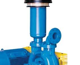
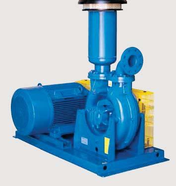
24 Seitenkanalverdichter für Druck- und Vakuumbetrieb - Sonderausführungen Blowers and exhausters for air - Special versions Modellreihe BD Version mit Riemenantrieb BD Series Belt drive version Anmerkung / Note: Hergestellt auch in Übereinstimmung mit der Europäische Richtlinie 9/9/EG (ATEX) für Zonen 1 und 2, 21 und 22. Also manufactured in conformity to the requirements of the European Directive 9/9/EC (ATEX) for Zones 1 and 2, 21 and 22. Modellreihe V Kompaktversion zur vertikalen Montage V Series Compact version in vertical axis Anmerkung / Note: Hergestellt auch in Übereinstimmung mit der Europäische Richtlinie 9/9/EG (ATEX) für Zonen 1 und 2, 21 und 22. Also manufactured in conformity to the requirements of the European Directive 9/9/EC (ATEX) for Zones 1 and 2, 21 and 22. Modellreihe VL Version zur vertikalen Montage mit Buchse und flexibler Kupplung zwischen Motor und Maschine VL Series Machine in vertical axis, with hub and flexible coupling between machine and motor Anmerkung / Note: Hergestellt auch in Übereinstimmung mit der Europäische Richtlinie 9/9/EG (ATEX) für Zonen 1 und 2, 21 und 22. Also manufactured in conformity to the requirements of the European Directive 9/9/EC (ATEX) for Zones 1 and 2, 21 and 22. Modellreihe HC Version zur horizontalen Montage, flexible Wellenkupplung zwischen Motor und Maschine HC Series Machine in horizontal axis, coupled to the motor via a flexible shaft coupling 2 Zusätzlich zu den oben dargestellten Versionen sind auf Anfrage weitere Sonderausführungen mit flexibler Kupplung oder Riemenantrieb lieferbar. Anmerkung / Note: Hergestellt auch in Übereinstimmung mit der Europäische Richtlinie 9/9/EG (ATEX) für Zonen 1 und 2, 21 und 22. Also manufactured in conformity to the requirements of the European Directive 9/9/EC (ATEX) for Zones 1 and 2, 21 and 22. In addition to the above listed versions, it is possible to supply other special units with motor direct coupled via a flexible shaft coupling or belt driven.
 [mm] [kg] CL.6/01 55 1,7 CL /01 1 1 1 19 90 78 FE...( ) CL 20 HS 255 1,5 CL 0-Z HS CL 1R.")
 CL 28/1 20 6,2 2 1/2 2 1/2 200 2 190 CL 80-Z HS 290 6, FE8...( ) IF8AHR7 CL 520 HS 2 1/2 2 200 2 85 190 6,8 FE8.")
 IF16AH CL 1R9 CL 2R9 07 27 50 290 165 12 FE16...( ) IFAG CL /21 1 1 1 19 155 90 78 1,5 FE.")
 IF8AG IF10AG IF16AG CL 18/01 CL 22/01 CL 17/21 CL 20/21 CL 2/21 CL /1 CL 0/21 CL 6/21 CL 2/21 CL 0/1 CL 6/1 CL 60/1 CL 9/21 CL 72/1 CL 8/1 CL 98/1 TBT/M 2 1/2 2 1/2 200")
 IFAH - IF5AH IF6AH - IF7AH IF8AH - IF8AHR7 IF10AHR7 - IF10AHR8 IF16AH IFAG - IF5AG IF6AG - IF7AG IF8AG - IF10AG IF16AG ( ) Die Filterpatronen sind in folgenden")
25 Zubehör - Accessories Typ Filter type IFAH IF5AH IF6AH IF7AH IF8AH Maschinentyp Machine type Ansaugfilter (Vakuumbetrieb) In-line filters for exhausters Ø A1 Ø A2 Ø B C D E F Gewicht Weight Filterpatrone Filter cartridge type ("gas) [mm] [kg] CL.6/ ,7 CL / FE...( ) CL 20 HS 255 1,5 CL 0-Z HS CL 1R.5 1 1/ 1 1/ ,7 FE5...( ) CL 220 HS CL 0 HS 20,1 CL 12/21 1 1/2 1 1/ FE6...( ) CL 20 HS 0, CL 50 HS 260 5, CL 1R CL 60 HS 60 5,8 CL 1/21 FE7...( ) CL 28/1 20 6,2 2 1/2 2 1/ CL 80-Z HS 290 6, FE8...( ) IF8AHR7 CL 520 HS 2 1/ ,8 FE8...( ) IF10AHR7 CL 720 HS (-, kw) 90 7, CL 720 HS (5,5-7,5 kw) 0 7 FE10...( ) IF10AHR8 CL 2R8 2 1/ ,5 FE10...( ) IF16AH CL 1R9 CL 2R FE16...( ) IFAG CL / ,5 FE...( ) IF5AG IF6AG CL 7/01 CL 7/21 CL 10/01 CL 10/21 1 1/ 1 1/ ,7 FE5...( ) 1 1/2 1 1/ ,1 FE6...( ) IF7AG CL 15/ ,7 FE7...( ) IF8AG IF10AG IF16AG CL 18/01 CL 22/01 CL 17/21 CL 20/21 CL 2/21 CL /1 CL 0/21 CL 6/21 CL 2/21 CL 0/1 CL 6/1 CL 60/1 CL 9/21 CL 72/1 CL 8/1 CL 98/1 TBT/M 2 1/2 2 1/ , FE8...( ) ,6 FE10...( ) FE16...( ) IFAH - IF5AH IF6AH - IF7AH IF8AH - IF8AHR7 IF10AHR7 - IF10AHR8 IF16AH IFAG - IF5AG IF6AG - IF7AG IF8AG - IF10AG IF16AG ( ) Die Filterpatronen sind in folgenden Ausführungen lieferbar: - FE C Harz behandeltes Papier - FE P Polyester - FE A antistatisches Polyester - FE I Edelstahl ( ) The filter cartridges are available made in the following versions: - FE... C resin treated paper - FE... P polyester - FE... A antistatic polyester - FE... I stainless steel 25
 [mm] [kg] F CL.6/01 CL /01 1 95 99 12 100 0, C.")
 F7 CL 15/01 2 190 167 18 15 1,5 C8...( ) F8 CL 18/01 CL 22/01 2 1/2 190 167 18 15 1,6 C8.")
 F6NG CL 0 HS 1 1/2 150 158 25 87 1,5 C6...( ) CL 50 HS F7NG CL 1R5.5 CL 60 HS 2 190 227 28 15 2,5 C8.")
 F10NGR7 CL 720 HS (-, kw) 80, 2 250 0 190 CL 720 HS (5,5-7,5 kw) 280 C10.")
 FG CL /21 1 95 19 100 100 0,5 C...( ) F5G CL 7/21 1 1/ 150 15 15 87 1,1 C6.")
 CL 2/21 CL 28/1 21 271 2 CL /1 2 270 CL 0/21 CL 6/21 0 26 CL 0/1 250 07 00 190 2, C10.")
 2 F - F5 - F6 F7 - F8 FNG - F5NG - F6NG F7NG - F1NG - F7NGR F8NGR - F10NGR7 F10NGR8 ( ) Die Filterpatronen sind in")
 The cartridges are available made in the following versions: - C... C resin treated paper - C.")
 Net-filters for")
26 Zubehör - Accessories Typ Filter type Maschinentyp Machine type Ansaugfilter (Druckbetrieb) Filters for blowers Ø A Ø B C D E Gewicht Weight Filterpatrone Cartridge type ("gas) [mm] [kg] F CL.6/01 CL / , C...( ) F5 CL 7/01 1 1/ ,9 C6...( ) F6 CL 10/01 1 1/ ,9 C6...( ) F7 CL 15/ ,5 C8...( ) F8 CL 18/01 CL 22/01 2 1/ ,6 C8...( ) FNG CL 20 HS ,7 C...( ) CL 0-Z HS F5NG CL 1R.5 CL 220 HS 1 1/ , C6...( ) F6NG CL 0 HS 1 1/ ,5 C6...( ) CL 50 HS F7NG CL 1R5.5 CL 60 HS ,5 C8...( ) F7NGR CL 20 HS 1 1/ ,5 C8...( ) F8NGR CL 520 HS , C8...( ) F10NGR7 CL 720 HS (-, kw) 80, CL 720 HS (5,5-7,5 kw) 280 C10...( ) F10NGR8 F1NG CL 80-Z HS CL 2R8 CL 1R9 CL 2R9 2 1/ ,6 C10...( ) C1...( ) FG CL / ,5 C...( ) F5G CL 7/21 1 1/ ,1 C6...( ) F6G CL 10/21 1 1/ ,1 C6...( ) F8/1G F10/1G CL 12/21 CL 1/21 CL 17/ CL 20/ C8...( ) CL 2/21 CL 28/ CL / CL 0/21 CL 6/ CL 0/ , C10...( ) CL 6/1 CL 60/ CL 2/21 CL 9/21 F1G CL 72/ ,5 C1...( ) CL 8/1 CL 98/1 F1 TBT/M , C1...( ) 2 F - F5 - F6 F7 - F8 FNG - F5NG - F6NG F7NG - F1NG - F7NGR F8NGR - F10NGR7 F10NGR8 ( ) Die Filterpatronen sind in folgenden Ausführungen lieferbar: - C C Harz behandeltes Papier - C P Polyester - C A antistatisches Polyester - C I Edelstahl ( ) The cartridges are available made in the following versions: - C... C resin treated paper - C... P polyester - C... A antistatic polyester - C... I stainless steel FG - F5G - F6G F8/1G - F10/1G F1G F1 Typ Filter type Netzfilter (Druckbetrieb) Net-filters for blowers Ø A Ø B C D Gewicht Weight ("gas) [mm] [g] 26 Filternetz und Filterdeckel aus Edelstahl (AISI 0) Gewindeanschluss aus Nylon (PA) Filtering net and cover in stainless steel (AISI 0) Threaded connection in Nylon (PA) FR FR5 1 1/ FR6 1 1/ FR FR8 2 1/ FR FR


27 Typ Filter type Maschinentyp Machine type Zweistufige Filter (Druckbetrieb) Two-stage filters for blowers Ø A Ø B C D Ø E Ø F G X Ø K J Zubehör - Accessories Gewicht Weight Filterpatrone Cartridge type [mm] [kg] FDS 7/6 CL 12/21-1/ CH6 FDS 8 CL 17/21-20/21-2/21-28/1 - / CH8 FDS 10 CL 0/21-6/21-0/ ,5 16 CH10 FDS 1/10 CL 2/21-6/1-60/ CH12 FDS 15/1 CL 9/21-72/1-8/ CH15 FDS 17/1 CL 98/ CH17 ØE D Befestigungsbügel Fixing brackets Zyklonischer Vorabscheider Cyclone pre-filter 1500 ØF X ØB ØA G Die Zweistufigen Filter vom Typ FDS sind für höchste Beanspruchungen in Umgebungen mit hoher Staubbelastung geeignet. Ein Großteil, des in der angesaugten Luft vorhandenen Staubes, wird im zyklonischem Vorabscheider und im Metallgehäuse des Filters abgeschieden. Eine mit Harz behandelte Filterpatrone aus Papier, welche im Filtergehäuse installiert ist, filtert die noch verbliebenen Feinstaubpartikel heraus. Bohrungen-holes ØK C J The two-stage filters, FDS type, are suitable for heavy duty applications in environments with strong presence of dust. Most of the dust contained in the sucked air is separated in a cyclone pre-filter and inside the metal housing of the filter. A resin treated paper cartridge, fitted in the filter housing, shall then retain the remaining finest particles of dust. Optische und Elektrische Indikatoren für die Filterwartung Die Indikatoren für die Filterwartung signalisieren wann die nächste Wartung der am Verdichter installierten Filter durchgeführt werden muss. Die Schutzart ist IP. Optische Indikatoren - Visual indicators Ø2.5 Filter service visual and electrical indicators The filter service indicators signal when maintenance on air filters fitted on blowers must be carried out. Their protection class is IP. Elektrische Indikatoren - Electrical indicators Ø /8" 1/8" Eine rote Markierung im Schauglas des Optischen Indikators signalisiert das Erreichen der Verschmutzungsgrenze der Filterpatrone. Die rote Markierung bleibt in Alarmstellung bis der Indikator durch Drücken an der Oberseite, nach Austausch der Filterpatrone, zurückgestellt wird. In the visual indicator the filter restriction limit is shown by a bright red flag that pops up behind the full-view window of the indicator. The red flag stays in the alarm position until the manual reset that is done by pushing on the top of the indicator. Durch das Schalten eines internen Kontaktes im Elektrischen Indikator wird das Erreichen der maximal zulässigen Verschmutzungsgrenze signalisiert. Dieses Signal kann verwendet werden, um eine Signalleuchte oder eine Signalhupe anzusteuern. Die Versorgungsspannung beträgt 12 oder 2 V und die maximal zulässige Leistungsaufnahme 6 Watt. In the electrical indicator, when the filter restriction level reaches the maximum admissible limit, an internal contact commutes and can be used to activate a light or a buzzer. The feeding voltage can be 12 or 2V and the maximum admissible load is 6 Watt. 27
 [mm] [kg] CL.6/01 10 SVT CL /01 1 8 0,9 CL /21 5 0,7 SV5/T CL 0-Z HS 1 1/ 120 92 0,8 CL 7/01 SV5/6T CL 1R.")
 SV8T CL 22/01 CL 80-Z HS 2 1/2 190 12,7 SV8/7T CL 18/01 (kw) 2 1/2 190 150 SV8/10T CL 2R8 2 1/2 25 18 6,5 CL 1R9")

 Pressure relief valves for blowers Typ Valve type SV7 SV8 SV10D SV10 SV15 Maschinentyp Machine type A")
![Gewicht Weight [mm] [kg] CL 12/21 CL 1/21 27 0,6 CL 28/1 27 0,9 CL /1 CL 17/21 28 1 CL 2/21 CL 0/1 CL 20/21 8 1, CL 6/1 CL 60/1 CL 0/21 CL 6/21 CL 2/21 27 2 1 1,7 CL 9/21 CL](/docs-images/77/74502274/images/28-4.jpg "72/1 CL 8/1 9 2 CL 98/1 Vakuumsicherheitsventile (Vakuumbetrieb) Vacuum relief valves for exhausters Typ Valve type Maschinentyp Machine type Gewicht Ø A B C Weight (\"gas)")
![[mm] [kg] VSV CL.6/01 CL /01 1 10 105 0,85 CL /21 5 0,65 CL 0-Z HS VSV5/6 CL 7/01 CL 1R.](/docs-images/77/74502274/images/28-5.jpg "5 CL 7/21 CL 220 HS 1 1/ 160 15 1,5 CL 10/01 VSV6 CL 0 HS CL 10/21 CL 12/21 CL 20 HS 1 1/2 15 15 1, CL 15/01 VSV7 CL 50 HS CL 1R5.")
28 SVT - SV5/6T - SV6T - SV7T SV8T - SV8/7T - SV8/10T - SV15T Zubehör - Accessories 28 Drucksicherheitsventile (Druckbetrieb) Pressure relief valves for blowers Typ Valve type Maschinentyp Machine type Ø A B C Gewicht Weight ("gas) [mm] [kg] CL.6/01 10 SVT CL / ,9 CL /21 5 0,7 SV5/T CL 0-Z HS 1 1/ ,8 CL 7/01 SV5/6T CL 1R.5 CL 7/21 CL 220 HS 1 1/ ,5 CL 10/01 SV6T CL 10/21 CL 0 HS CL 20 HS 1 1/ , CL 15/01 SV7T CL 50 HS CL 1R5.5 CL 60 HS CL 520 HS CL 720 HS ,1 CL 18/01 (1,5-kW) SV8T CL 22/01 CL 80-Z HS 2 1/ ,7 SV8/7T CL 18/01 (kw) 2 1/ SV8/10T CL 2R8 2 1/ ,5 CL 1R9 SV15T TBT/M CL 2R Abhängig von den jeweiligen Gegebenheiten kann das Vakuumsicherheitsventil zusätzlich mit einem Schalldämpfer und/oder einem Filter versehen werden, um das Eindringen von Staubpartikeln in die Maschine zu verhindern. Depending on where the exhauster is installed, the vacuum relief valve can be fitted with a silencer, as well as a filter, to prevent ingress of dust into the machine. SV7 - SV8 - SV10 SV10D - SV15 Drucksicherheitsventile (Druckbetrieb) Pressure relief valves for blowers Typ Valve type SV7 SV8 SV10D SV10 SV15 Maschinentyp Machine type A Gewicht Weight [mm] [kg] CL 12/21 CL 1/ ,6 CL 28/1 27 0,9 CL /1 CL 17/ CL 2/21 CL 0/1 CL 20/21 8 1, CL 6/1 CL 60/1 CL 0/21 CL 6/21 CL 2/ ,7 CL 9/21 CL 72/1 CL 8/1 9 2 CL 98/1 Vakuumsicherheitsventile (Vakuumbetrieb) Vacuum relief valves for exhausters Typ Valve type Maschinentyp Machine type Gewicht Ø A B C Weight ("gas) [mm] [kg] VSV CL.6/01 CL / ,85 CL /21 5 0,65 CL 0-Z HS VSV5/6 CL 7/01 CL 1R.5 CL 7/21 CL 220 HS 1 1/ ,5 CL 10/01 VSV6 CL 0 HS CL 10/21 CL 12/21 CL 20 HS 1 1/ , CL 15/01 VSV7 CL 50 HS CL 1R5.5 CL 60 HS CL 1/21 CL 520 HS CL 720 HS CL 18/01 CL 22/01 CL 17/21 CL 20/21 VSV8 CL 2/21 CL 28/1 CL /1 CL 80-Z HS 2 1/ ,7 VSV8/10 CL 2R8 2 1/ ,5 CL 0/21 CL 6/21 CL 2/21 VSV10 CL 0/1 CL 6/1 CL 60/ ,6 CL 9/21 CL 72/1 CL 8/1 VSV15 CL 98/1 TBT/M CL 1R9 CL 2R

 [mm] [kg] 1 65 65 2 0,65 1 1/ 75 78 8 0,85 1 1/2 8 8 52 1 2 98")

![5 CL 60 HS CL 520 HS CL 720 HS Ø A B C Ø D Gewicht Weight ("gas) [mm] [kg] 1 1/ 55-6 50 6,5 0,17 1 1/2 72 50 6,5 0,2 2 82,5 50 9 0,2 5 D C](/docs-images/77/74502274/images/29-4.jpg "Schlauchstutzen mit Gewinde für flexiblen Schlauch Threaded connections for flexible pipe Typ Connection type Ø A Ø B Ø C Ø D Gewicht Weight (\"gas) [mm]")
29 Zubehör - Accessories Typ Valve type VR VR5 VR6 VR7 VR8 VR10 VR15 Rückschlagventile Non return valves Maschinentyp Machine type CL 20 HS CL.6/01 CL /01 CL /21 CL 0-Z HS CL 7/01 CL 1R.5 CL 7/21 CL 220 HS CL 10/01 CL 0 HS CL 10/21 CL 12/21 CL 20 HS CL 15/01 CL 50 HS CL 1R5.5 CL 60 HS CL 1/21 CL 520 HS CL 720 HS CL 18/01 CL 22/01 CL 17/21 CL 20/21 CL 2/21 CL 28/1 CL /1 CL 80-Z HS CL 2R8 CL 0/21 CL 6/21 CL 2/21 CL 0/1 CL 6/1 CL 60/1 CL 9/21 CL 72/1 CL 8/1 CL 98/1 CL 1R9 CL 2R9 TBT/M Ø A B C D Gewicht Weight ("gas) [mm] [kg] ,65 1 1/ ,85 1 1/ ,6 2 1/ , , Flanschstutzen für flexiblen Schlauch Flanged connections for flexible pipe Typ Connection type HF 1 HF 2 HF Maschinentyp Machine type CL 0-Z HS CL 1R.5 CL 220 HS CL 0 HS CL 20 HS CL 50 HS CL 1R5.5 CL 60 HS CL 520 HS CL 720 HS Ø A B C Ø D Gewicht Weight ("gas) [mm] [kg] 1 1/ ,5 0,17 1 1/ ,5 0,2 2 82, ,2 5 D C Schlauchstutzen mit Gewinde für flexiblen Schlauch Threaded connections for flexible pipe Typ Connection type Ø A Ø B Ø C Ø D Gewicht Weight ("gas) [mm] [kg] HF15 HF10 HF8 HF B A HF ,1 HF 8 2 1/ ,2 HF , HF ,6 29
![Zubehör - Accessories Typ Hose type Flexible Schlauchverbindungen Flexible hoses Ø A B Gewicht Weight ("gas) [mm] [kg] FH - FH5 - FH6 FH 1 15 0,5 FH5 1 1/ 15 0,9 FH6 1 1/2 20 1, FH7 2 20 0,6 FH7 -](/docs-images/77/74502274/images/30-0.jpg "FH8 - FH10 - FH15 FH8 2 1/2 20 0,7 FH10 20 1 FH15 20 1,5 Schalldämpfer mit zwei Gewindeanschlüssen Two-connection silencers Typ Silencer type Ø A Ø B C D E Gewicht Weight (\"gas) [mm] [kg] SSI 1 69")
 [mm] [kg] SSF 1 69 158 18 20 0, SSF 5 1 1/ 69 190 18 52 2 0, B A F B SSF 6 1 1/2 80")

30 Zubehör - Accessories Typ Hose type Flexible Schlauchverbindungen Flexible hoses Ø A B Gewicht Weight ("gas) [mm] [kg] FH - FH5 - FH6 FH ,5 FH5 1 1/ 15 0,9 FH6 1 1/2 20 1, FH ,6 FH7 - FH8 - FH10 - FH15 FH8 2 1/2 20 0,7 FH FH ,5 Schalldämpfer mit zwei Gewindeanschlüssen Two-connection silencers Typ Silencer type Ø A Ø B C D E Gewicht Weight ("gas) [mm] [kg] SSI , B A A B SSI 5 1 1/ ,5 SSI 6 1 1/ ,5 E D E C SSI ,6 SSI 8 2 1/ ,1 SSI , SSI ,5 Schalldämpfer mit einem Gewindeanschluss Single connection silencers Typ Silencer type Ø A Ø B C D E Ø F Gewicht Weight ("gas) [mm] [kg] SSF , SSF 5 1 1/ , B A F B SSF 6 1 1/ , SSF ,5 SSF 8 2 1/ ,9 SSF ,1 SSF ,9 E C D 0 Manometer und Vakuummeter mit Glyzerinbad Glycerine filled pressure and vacuum gauges Edelstahlgehäuse Anschluss: G 1/ Normalisierte Skalen: Manometer: 0 0,5 bar 0 1 bar Vakuummeter: kpa Stainless steel case Bottom connection G 1/ Normalized range: pressure gauges: 0 0,5 bar 0 1 bar vacuum gauges: kpa G ¼"


31 Zubehör - Accessories Schallschutzhauben Schallschutzhauben sind für jeden Maschinentyp verfügbar. Sie bestehen aus einzeln abnehmbaren Dämmplatten, die mit galvanisiertem Stahl verkleidet sind. Die einzelnen Platten werden durch außen montierte Klammern zusammengehalten, die ebenfalls galvanisiert sind. Auf Anfrage können die Klemmen in rostfreiem Stahl geliefert werden. Der jeweilige Schalldruckpegel wird um 12 db(a) reduziert. Die Schallschutzhauben für alle Seitenkanalverdichter im Vakuumbetrieb und Verdichter, die mit einer Motorleistung über kw im Druckbetrieb arbeiten, werden zusätzlich mit einem nahezu geräuschlosen elektrischen Ventilator ausgestattet. Für nähere Information oder Dimensionierung einer Schallschutzhaube kontaktieren Sie bitte unseren Vertrieb. Acoustic enclosures Acoustic enclosures are available for each type of machine. They are made up from independently removable acoustic panels externally clad with galvanized sheet steel. The panels are fixed together with externally mounted clamps, galvanized as well. On request, clamps in stainless steel could be supplied. Sound pressure levels are reduced by about 12 db(a). The acoustic enclosures, for all side channel exhausters and for blowers with motor power above kw, are fitted with an electrically operated ventilation fan with sound deadened duct. Please contact our Sales Department for detailed information and for the dimensions of the acoustic enclosures. Umschaltventile Das Umschaltventil aus einer Aluminiumlegierung kann benutzt werden, um den Luftstrom in einer Leitung innerhalb von Zehntel-Sekunden umzukehren. Das Ventil kann entweder pneumatisch oder elektromagnetisch gesteuert werden (Steuerung mit 20 V AC oder 2 V DC). Außer den unten gezeigten Versionen mit einem Kolben, sind zusätzlich Geräte mit zwei unabhängigen Kolben und zwei pneumatischen Antrieben verfügbar. Für ausführlichere Informationen setzten Sie sich bitte mit unserem Vertrieb in Verbindung. Flow changeover devices The flow changeover devices, made of aluminium alloy, can be used to reverse the air flow direction in a pipeline in a time round to some tenth of a second. They can be operated by pneumatic actuator or electromagnet with 20V a.c. or 2V d.c. feeding. Besides the versions with single piston shown below, other devices are also available with two independent pistons and two pneumatic actuators. Please contact our Sales Department for more detailed information. Version OOP Pneumatisch gesteuert Pneumatic operation Version OOE Elektro-magnetisch gesteuert Electric operation Version OCP Pneumatisch gesteuert Pneumatic operation Version OCE Elektro-magnetisch gesteuert Electric operation Typ Device type A B C C1 D E F G H I Anschluss Connect. Ø Gewicht pneum. Gewicht elektro-magn. Weight with Weight with pneumatic feeding electric feeding [mm] ("gas) [kg] FCD ", 6,8 FCD " 9,5 Version OCE Version OOP Version OOE Version OCP 1
 Konstruktionsmerkmale Um entflammbare Gase, wie Biogas oder Methangas zu")

32 SEITENKANALVERDICHTER FÜR ENTFLAMMBARE GASE SIDE CHANNEL BLOWERS FOR COMBUSTIBLE GASES Verdichter für Biogas, Erdgas oder entflammbare Gase, für die Zonen 1 und 2, gemäß der Richtlinie 9/9/EG (ATEX) Blowers for biogas, natural gas or combustible gases, for Zones 1 and 2, in conformity with the 9/9/EC Directive (ATEX) Konstruktionsmerkmale Um entflammbare Gase, wie Biogas oder Methangas zu fördern oder zu verdichten, sind eine Reihe gasdichter Seitenkanalverdichter mit einer speziellen Herstellungstechnologie entwickelt worden. Diese sind durch folgende Handelsmarke gekennzeichnet: Features of construction To extract or compress combustible gases, such as biological gas or methane gas, a complete range of gas-tight side channel blowers has been designed, featuring a specific manufacturing technology, identified by the trademark: Hauptkonstruktionsmerkmale dieses Maschinentyps sind: Gehäuse und Laufrad aus komplett funkengeschützter Aluminiumlegierung; Gehäuse sind mit Loctite imprägniert; versiegelte Gehäusehälften; Wellenabdichhtung erfolgt über eine spezielle schmierfreie Doppellippendichtung; Explosionsgeschützte Elektromotoren, mit minimaler Schutzklasse Ex-d IIB T, IP 55, für Zone 1; Funkenfreie Elektromotoren, mit minimaler Schutzklasse Ex-nA IIT, IP 65, für Zone 2. Motoren gemäß NEMA, SABS und anderen Standards sind ebenfalls auf Anfrage erhältlich. Die konstruktiv einfachste Lösung ist die sogenannte KOMPAKTVERSION. Bei dieser Version ist der Motor direkt am Gehäuse des Verdichters befestigt und das dynamisch ausgewuchtete Laufrad ist direkt an die Motorwelle angebracht. Des Weiteren sind Maschinen mit freien Wellenenden, sowie Maschinen mit flexiblen Wellenkupplungen und Maschinen mit Riemenantrieb lieferbar. Bei letzteren bestehen die Antriebsabdeckungen aus funkenfreiem Material. The main characteristics of construction of these machines are: casing and impellers made completely of spark proof aluminium alloy; static parts in contact with the gas impregnated with Loctite; casing halves sealed; shaft sealing by special double-lip seals which do not require lubrication; explosion-proof electric motors, with minimum protection class Ex-d IIB T - IP 55 for Zone 1; non-sparking motors, with minimum protection class Ex-nA II T - IP 65 for Zone 2. Motors in accordance with NEMA, SABS and other Standards can be supplied upon request. The simplest solution for the manufacturing of the machines is the so-called CLOSE COUPLED version - i.e., a flange mounted electric motor is bolted to the blower casing; the impeller, which is dynamically balanced, is fitted directly onto the motor shaft extension. Furthermore we can offer machines with their own shaft and bearings and coupled to the electric motors via flexible shaft couplings or belt drives. In these cases, the safety drive guards are made from sparkfree material. The most common fields of applications Landfill biogas recovery to feed torch, burner or gas engine; tank, plant or contaminated soil gas recovery to feed torch or burner; extraction of biogas from gasometer, natural gas from pipeline or gasometer and burner or gas engine feeding. 2 Haupteinsatzgebiete Biogasgewinnung zur Befeuerung von Brennern, Öfen oder Motoreinspeisungen; Faulgasgewinnung zur Befeuerung von Brennern und Öfen; Absaugung von Biogas oder Erdgas aus Gasometern und Rohren.


 können Verdichter mit Elektromotoren ausgestattet werden, die für einen Betrieb mit einem Frequenzumrichter geeignet sind.")

33 Maschinen mit Gasrückführung (Bypass) Zur Erzeugung variabler Gas-Volumenströme wird ein mit geeignetem Drucksicherheitsventil versehener Bypass zwischen Auslass- und Ansaugstutzen installiert - eine einfache aber effektive Lösung. Bei steigendem Volumenstrom erhöht sich der Druck. Sobald der eingestellte Druckpunkt erreicht ist, öffnet sich das Drucksicherheitsventil und das überschüssige Gas wird dem System per Bypass erneut zugeführt. In der Regel ist das Bypass-Kreislaufsystem in der Lage, die volle Verdichterkapazität aufzunehmen. Folglich kann der Verdichter weiterlaufen, selbst wenn der angeforderte Gas-Volumenstrom gleich null ist. Ein geeignetes Kühlsystem kann zusätzlich installiert werden, falls die Gasrückführung ohne entsprechende Kühlung nicht möglich ist. Maschinensteuerung mittels Frequenzumrichter Wenn die Gasnachfrage zeitlich variiert (z.b. bei einem Brenner oder bei einer Motoreinspeisung) können Verdichter mit Elektromotoren ausgestattet werden, die für einen Betrieb mit einem Frequenzumrichter geeignet sind. Der Drehzahlbereich des Verdichters (und somit auch die Ansteuerfrequenz des Elektromotors) wird abhängig von den vorausgesetzten Betriebsbedingungen, genau auf den erwarteten Differenzdruck zwischen Ein- und Ausgang des Verdichters eingestellt. Die Drehzahl des Motors muss dabei über einen Prozessparameter Gasaustrittsdruck gesteuert werden. Zubehör Eine Reihe an Zubehörteilen ist für diesen Maschinentyp lieferbar: Gasdichte Filter; Flanschkompensatoren mit Edelstahlbalg; Rückschlagventile; Druck- und Temperaturanzeiger; Druck- und Temperaturschalter; manuelle und automatische Absperrventile; Schallschutzhauben. auben. Machines with gas recirculation (by-pass) When a variable flow rate is required, a by-pass line between outlet and inlet, and in which a suitable pressure relief valve is fitted, is a simple and effective solution. When the gas demand decreases, the outlet pressure increases, and, when the set pressure is reached, the pressure relief valve begins to open and by-passes gas back to the blower suction. Usually, the by-pass circuit is capable of handling the full capacity of the blower and thus the machine can continue to run even if the downstream gas demand is zero. A suitable cooler will be installed if complete recirculation is not possible without gas cooling. Machines controlled via frequency inverter If the gas demand varies in time (such as for burner or engine feeding), we can supply blowers equipped with a motor intended for control via frequency inverter. The rpm range of the blower (and therefore the output frequency range of the frequency inverter) can be adjusted according to the foreseen operating conditions, and in particular to the expected differential pressure between blower discharge and suction. The speed of rotation of the motor shall be controlled via the "discharge gas pressure" process parameter. Accessories A complete range of accessories is available, including the following: gas-tight filters; stainless steel flanged flexible connection bellows; non return valves; pressure gauges and thermometers; pressure switches and temperature switches; manual and automatic cut-off valves; acoustic enclosures. Für weitere Details zu Seitenkanalverdichtern für entflammbare Gase, insbesondere für Biogas, fragen Sie bitte unseren Vertrieb nach der spezifischen Broschüre COD For more details on side channel blowers for combustible gases, more specifically for biogas, please ask to our Sales Department the specific brochure COD

34 DER TBT VERDICHTER, DRUCK- UND VAKUUMBETRIEB TBT BLOWERS AND EXHAUSTERS Der TBT ist eine Maschine mit ringförmigem, peripheren Kanal, ähnlich dem Seitenkanalverdichter, jedoch ausgestattet mit dem revolutionären Heliflow-Laufrad und einem nach aufwendigen Untersuchungen und Tests entwickelten Spezialkanal. Die besondere Form des Laufrades und des Kanals ermöglichen es, vergleichbare Leistungsdaten wie bei Drehkolbengebläse zu erzielen. Die typischen Probleme entstehen beim TBT jedoch nicht. Vorteile gegenüber Drehkolbengebläse: leiser Betrieb (10-15dB weniger als bei Drehkolbengebläsen); vibrationsfrei; pulsationsfrei; ölfrei; wartungsarm (Reinigung des Ansaugfilters und gelegentliches Einfetten der Lagerungen). Ein Austausch der Lagerungen kann ohne Demontage des Gehäuses durchgeführt werden. Beim TBT wird das angesaugte Gas parallel entlang der beiden peripheren Kanäle gedrückt. Optional können Ein- und Ausgang so modifiziert werden, dass ein Kanal ungenutzt bleibt, wodurch die Maschine (TBT-HF) mit halbem Volumenstrom bei gleichem Differenzdruck arbeitet. Da die für die Maschine zulässigen Umdrehungszahlen ( U/min) eine große Bandbreite aufweisen, kann mit einer einzigen Maschine ein sehr breites Betriebs Spektrum abgedeckt werden. Gehäuse und Laufrad bestehen aus Aluminiumlegierung, die Antriebswelle aus legiertem Stahl. Durch die Verwendung verschiedener Wellendichtungen ist der Betrieb mit den meisten Industriegasen sowie Erdgas und Biogas möglich. Bei korrosiven Gasen werden exponierte Teile mit Spezialbeschichtungen versehen. Um allen Applikationen gerecht zu werden, steht eine breite Palette an Zubehörteilen zur Verfügung: z.b. Filter, Schalldämpfer, flexible Schlauchverbindungen, Rückschlagventile, Druck- und Vakuumsicherheitsventile, manuelle und automatische Abschaltventile, Druck- und Vakuumanzeiger, Temperaturanzeiger, Temperaturschalter, Druckschalter und Schallschutzhauben. The TBT blowers and exhausters are machines with a peripheral toroidal channel, similar to side channel blowers, but with a revolutionary heliflow impeller and channel developed through long research and tests. With this impeller and channel design, performances similar to positive displacement machines can be achieved, with none of the associated problems and, indeed, with some added advantages: quiet operation (10 15 db less than a positive displacement machine); vibration free; pulsation free; oil free; low maintenance (inlet filter cleaning and occasional greasing of the bearings only). Bearing replacement Zwei kanäle parallel can be carried out Two channels in parallel without dis as sembling the machine casing. In the TBT design, the aspirated gas is forced along the two peripheral channels in parallel, or, by modifying the inlet and outlet porting, one of the channels can be excluded thus obtaining a machine (TBT-HF) with half the flow rate at the same outlet pressure. Because of the wide range of permissible Heliflow-Laufrad operating speeds of Heliflow impeller rotation (from 2000 to 5500 rpm), a very large operating range can be achieved using a single machine size. The casing and impeller are made from aluminium alloy and the shaft from alloy steel. By using different types of shaft sealing, most industrial gases as well as natural and biological gases can be handled. In the case of corrosive gases, the internal wetted parts canbe treated or lined with protective coatings. To suit all applications, a complete range of accessories is available, such as: filters, silencers, flexible hoses, non return valves, pressure and vacuum relief valves, manual and automatic cut-off valves, pressure gauges, thermometers, vacuum gauges, temperature switches, pressure switches, acoustic enclosures.
 for Zones 1 and 2, 21 and 22.")
![Abmessungen [mm] Flanschanschluss Gewicht Motorleistung Anzahl Pole Dimensions [mm] Flanged connections Weight Motor power Ausgang Ausgang Motor poles [kw] A B C D E Ø F G H I L M outlet outlet [kg]](/docs-images/77/74502274/images/35-1.jpg "Ø 2 Ø 2 oder/or 670 85 2 670 95 15 695 05 18,5 2 oder/or 700 bei Volumenstrom bei Volumenstrom 15 2 10 650 1280 510 10 900 550 705 600 m /h > 600 m /h 5 22 70 50 0 2 oder/or 20 15 820 0 For flow")
 für Zonen 1 und 2, 21 und 22.")
![Abmessungen [mm] Flanschanschluss Gewicht Motorleistung Anzahl Pole Dimensions [mm] Flanged connections Weight Motor power Eingang Ausgang Motor poles [kw] A B C D E Ø F G H I L M inlet outlet [kg] Ø](/docs-images/77/74502274/images/35-3.jpg "1 Ø 2 2 oder/or 670 55 15 2 670 60 695 65 18,5 2 oder/or 700 80 22 2 10 650 1280 510 120 650 190 705 00 20 220 70 0 PN10 DN100 PN10 DN80 15 0 2 oder/or 820 60 7 2 820 85 860 500 5 2 860 525 150 800")
35 TBT Druckbetrieb - Abmessungen TBT blower - dimensions Anmerkung / Note: Hergestellt auch in Übereinstimmung mit der Europäische Richtlinie 9/9/EG (ATEX) für Zonen 1 und 2, 21 und 22. Also manufactured in conformity to the requirements of the European Directive 9/9/EC (ATEX) for Zones 1 and 2, 21 and 22. Abmessungen [mm] Flanschanschluss Gewicht Motorleistung Anzahl Pole Dimensions [mm] Flanged connections Weight Motor power Ausgang Ausgang Motor poles [kw] A B C D E Ø F G H I L M outlet outlet [kg] Ø 2 Ø 2 oder/or ,5 2 oder/or 700 bei Volumenstrom bei Volumenstrom m /h > 600 m /h oder/or For flow rates For flow rates m /h > 600 m /h PN10 DN80 PN10 DN oder/or oder/or TBT Vakuumbetrieb - Abmessungen TBT exhauster - dimensions Anmerkung / Note: Hergestellt auch in Übereinstimmung mit der Europäische Richtlinie 9/9/EG (ATEX) für Zonen 1 und 2, 21 und 22. Also manufactured in conformity to the requirements of the European Directive 9/9/EC (ATEX) for Zones 1 and 2, 21 and 22. Abmessungen [mm] Flanschanschluss Gewicht Motorleistung Anzahl Pole Dimensions [mm] Flanged connections Weight Motor power Eingang Ausgang Motor poles [kw] A B C D E Ø F G H I L M inlet outlet [kg] Ø 1 Ø 2 2 oder/or ,5 2 oder/or PN10 DN100 PN10 DN oder/or
36 TBT Druckbetrieb Die im Diagramm angegebenen Werte beziehen sich auf angesaugte Luft unter Bedingungen bei 20 C und 101, kpa abs. = 101 mbar abs. TBT blower The diagrams values refer to air at the suction conditions of 20 C and 101, kpa abs. = 101 mbar abs. TBT (mit 2 Kanälen) (two operating channels) TBT-HF (mit 1 Kanal) (only one operating channel) Volumenstrom [m /h] - Flow rate [m /h] Toleranz: ± 5% Tolerance: ± 5% 0,2 bar 0, bar 0, bar 0,7 bar 0,6 bar 0,5 bar 0,8 bar 0,8 0,7 0,6 bar bar bar 0,5 bar 0, bar 0, bar 0,2 bar Leistungsaufnahme [kw] - Absorbed power [kw] Volumenstrom [m /h] - Flow rate [m /h] Toleranz: ± 5% Tolerance: ± 5% 0,2 bar 0, bar 0, bar 0,7 bar 0,6 bar 0,5 bar 0,8 bar 0,8 0,7 0,6 bar bar bar 0,5 bar 0, bar 0, bar 0,2 bar Leistungsaufnahme [kw] - Absorbed power [kw] Drehzahlbereich [U/min] - Speed of rotation [rpm] Drehzahlbereich [U/min] - Speed of rotation [rpm] Anmerkung / Note: Hergestellt auch in Übereinstimmung mit der Europäische Richtlinie 9/9/EG (ATEX) für Zonen 1 und 2, 21 und 22. Also manufactured in conformity to the requirements of the European Directive 9/9/EC (ATEX) for Zones 1 and 2, 21 and 22. Temperaturerhöhung [ C] Temperature rise [ C] Toleranz: ± 5% Tolerance: ± 5% 0,8 bar 0,7 bar 0,6 bar 0,5 bar 0, bar 0, bar 0,2 bar Drehzahlbereich [U/min] - Speed of rotation [rpm] 6 Schalldruckpegel db(a) bei 1 m Abstand Sound level db(a) at 1 m Drehzahlbereich [U/min] Druckdifferenz [bar] (Überdruck) Outlet pressure [bar] Speed of rotation [rpm] 0,1 0,2 0, 0, 0,5 0,6 0,7 0, Der Schalldruckpegel wird nach dem Standard EN ISO 2151 in 1 Meter Abstand gemessen. Toleranz der Schalldruckpegel: ± db(a). Die jeweiligen Schalldruckpegel beziehen sich auf 2-polige Motoren. Bei -poligen Motoren liegen die Werte in der Regel darunter. The noise level is intended as sound pressure level (SPL), measured in free field, in accordance with the Standard EN ISO Tolerance on sound level values: ± db(a). The sound levels are for blowers with 2 pole motor. With pole motor the sound level can even be lower.
![Druckdifferenz (Überdruck) Outlet pressure [hpa=mbar] [U/min] [rpm] TBT mit 2 Kanälen - Leistungsdaten Druckbetrieb TBT blower with two operating channels - Performance table 2000 2250 2500 2750 000](/docs-images/77/74502274/images/37-0.jpg "250 500 750 000 250 500 750 5000 5250 5500 200 250 00 50 00 50 500 550 600 650 700 750 800 Q [m³/h] 70 585 700 815 925 105 5 1250 155 155 1555 1655 1755 1850 190 t [ C] 2 2 2 5 6 7 8 9 1 7 N [kw] 5,9")
37 Druckdifferenz (Überdruck) Outlet pressure [hpa=mbar] [U/min] [rpm] TBT mit 2 Kanälen - Leistungsdaten Druckbetrieb TBT blower with two operating channels - Performance table Q [m³/h] t [ C] N [kw] 5,9 7,1 8,5 9,9,6 1,2 1,8 16,8 18, ,5 27,8 0,2,5 Q [m³/h] t [ C] N [kw] 7 8, 9,9,5 1,2 1,9 16,7 18,8 20,9 2,1 25, 27,7 0,5, 7,5 Q [m³/h] t [ C] N [kw] 8,2 9,7, 1 1,8 16,7 18,7 20,8 2 25,2 27,5 0,2 6, 0,9 Q [m³/h] t [ C] N [kw] 9, 12,7 1,5 16, 18, 20,5 22,8 25, 28 0,8,7 7 0,, Q [m³/h] t [ C] N [kw] 10,7 12, 1,2 16,1 18,1 20,2 22, ,7 0,5, 6, 9,7,2 7,2 Q [m³/h] t [ C] N [kw] 1 15,9 17,8 19,7 22 2,6 27,2 29,9 2,9 6 9,2 2,8 6,5 50, Q [m³/h] t [ C] N [kw] 15,6 17,5 19,5 21,5 2,8 26, 29,1 2,1 5, 8,7 5,8 9,5 5,6 Q [m³/h] t [ C] N [kw] 19 20,9 2,1 25,8 28,6 1,5,6 7,8 1,1,7 8,5 52, Q [m³/h] t [ C] N [kw] 22, 2,9 27,7 0,6,6 6,6 0,6 7, 51,2 55, Q [m³/h] t [ C] N [kw] 2,6 26,6 29,7 2,8 5,9 9,1 2,6 6, 50, 5,6 Q [m³/h] t [ C] N [kw] 28, 1,,6 7,9 1, 5 8,9 52,9 Q [m³/h] t [ C] N [kw],5 6,7 0,6 7, 51, 55,5 Q [m³/h] t [ C] N [kw] 8, ,8 Die Leistungsdaten beziehen sich auf Luft unter Ansaugbedingungen von 20 C und 101, kpa abs. = 101 mbar abs. Q: Volumenstrom - Toleranz: ± 5% Δt: Temperaturerhöhung - Toleranz: ± 5% N: Wellenleistung - Toleranz: ± 5% The values shown in the table refer to air at the suction conditions of 20 C and 101, kpa abs. = 101 mbar abs. Q: flow rate - Tolerance: ± 5% Δt: temperature rise - Tolerance : ± 5% N: absorbed power at TBT blower shaft - Tolerance: ± 5% 7
38 TBT Vakuumbetrieb Die im Diagramm angegebenen Werte beziehen sich auf Luft bei 20 C. Die Volumenströme beziehen sich auf das jeweilige Ansaugvakuum. Am Outlet wurden 101, kpa abs. = 101 mbar abs. berücksichtigt. TBT exhauster The diagrams values refer to air at 20 C. The flow rates refer to the suction pressure. The discharge pressure is considered at 101, kpa abs. = 101 mbar abs. TBT (mit 2 Kanälen) (two operating channels) TBT-HF (mit 1 Kanal) (only one operating channel) Volumenstrom [m /h] - Flow rate [m /h] Toleranz: ± 5% Tolerance: ± 5% -0,1 bar -0,2 bar -0, bar -0, bar -0,5 bar -0,5 bar -0, bar -0, bar -0,2 bar -0,1 bar Leistungsaufnahme [kw] - Absorbed power [kw] Volumenstrom [m /h] - Flow rate [m /h] Toleranz: ± 5% Tolerance: ± 5% -0,1 bar -0,2 bar -0, bar -0, bar -0,5 bar -0,5 bar -0, bar -0, bar -0,2 bar -0,1 bar Leistungsaufnahme [kw] - Absorbed power [kw] Drehzahlbereich [U/min] - Speed of rotation [rpm] Drehzahlbereich [U/min] - Speed of rotation [rpm] Anmerkun / Note: Hergestellt auch in Übereinstimmung mit der Europäische Richtlinie 9/9/EG (ATEX) für Zonen 1 und 2, 21 und 22. Also manufactured in conformity to the requirements of the European Directive 9/9/EC (ATEX) for Zones 1 and 2, 21 and 22. Temperaturerhöhung [ C] Temperature rise [ C] Toleranz: ± 5% Tolerance: ± 5% -0,5 bar -0, bar -0, bar -0,2 bar -0,1 bar Drehzahlbereich [U/min] - Speed of rotation [rpm] 8 Schalldruckpegel db(a) bei 1 m Abstand Sound level db(a) at 1 m Drehzahlbereich [U/min] Druckdifferenz [bar] (Unterdruck) Inlet vacuum [bar] Speed of rotation [rpm] -0,1-0,15-0,2-0,25-0, -0,5-0, -0, Der Schalldruckpegel wird nach dem Standard EN ISO 2151 in 1 Meter Abstand gemessen. Toleranz der Schalldruckpegel: ± db(a). Die jeweiligen Schalldruckpegel beziehen sich auf 2-polige Motoren. Bei -poligen Motoren liegen die Werte in der Regel darunter. The noise level is intended as sound pressure level (SPL), measured in free field, in accordance with the Standard EN ISO Tolerance on sound level values: ± db(a). The sound levels are for exhausters with 2 pole motor. With pole motor the sound level can even be lower.
![Druckdifferenz (Unterdruck) Inlet vacuum [hpa=mbar] [U/min] [rpm] TBT mit 2 Kanälen - Leistungsdaten Vakuumbetrieb TBT exhauster with two operating channels - Performance table 2000 2250 2500 2750](/docs-images/77/74502274/images/39-0.jpg "000 250 500 750 000 250 500 750 5000 5250 5500-100 -150-200 -250-00 -50-00 -50 Q [m³/h] 595 710 825 90 105 6 1265 165 165 1565 1665 1765 1865 1965 2070 t [ C] 16 16 16 17 17,5 18 19 20 21 22 2 2 25")
![26 27 N [kw],,7 5,5 6, 7, 8, 9,5 10,6,7 12,8 1 15, 17 18,7 Q [m³/h] 505 60 750 865 980 1090 1200 0 0 1510 1610 1710 1810 1910 2015 t [ C] 27 26 25 25 26 26,5 27 27,5 28 29 0 1 5 7 N [kw], 5,2 6,1 7,1](/docs-images/77/74502274/images/39-1.jpg "8,2 9, 10,5,7 1 1, 15,6 16,9 18,6 20,7 2,5 Q [m³/h] 15 50 665 785 905 1020 0 120 150 150 1550 1650 1760 1860 1965 t [ C] 9 7 6 5,5 5 6 6,5 7 7,5 8 9 0 1 N [kw] 5,6 6,5 7,5 8,6 9,8,1 12,5 1,9 15, 16,7")
39 Druckdifferenz (Unterdruck) Inlet vacuum [hpa=mbar] [U/min] [rpm] TBT mit 2 Kanälen - Leistungsdaten Vakuumbetrieb TBT exhauster with two operating channels - Performance table Q [m³/h] t [ C] , N [kw],,7 5,5 6, 7, 8, 9,5 10,6,7 12,8 1 15, 17 18,7 Q [m³/h] t [ C] , , N [kw], 5,2 6,1 7,1 8,2 9, 10,5,7 1 1, 15,6 16,9 18,6 20,7 2,5 Q [m³/h] t [ C] , ,5 7 7, N [kw] 5,6 6,5 7,5 8,6 9,8,1 12,5 1,9 15, 16,7 18,1 19,8 21,7 2,7 25,9 Q [m³/h] t [ C] , ,5 8 8, ,5 5 N [kw] 6,8 7,9 9 10,1, 12,8 1, 15,8 17, 18,9 20,5 2 2,2 26, 28,8 Q [m³/h] t [ C] , , N [kw] 8,1 9, 10,5,7 12,9 1, 16 17,7 19, 21,1 2 2, ,1 1,6 Q [m³/h] t [ C] ,5 75, N [kw] 12 1, 1,6 16,2 17,9 19,7 21,5 2, 25, 27, 29,5 1,7,1 Q [m³/h] t [ C] ,5 9 9 N [kw] 16, 17,9 19,7 21,5 2, 25, 27,5 29,6 1,9,5 6,5 Q [m³/h] t [ C] N [kw] 21,5 2, 25, 27, 29,5 1,6,9 6,2 8,6 Die Leistungsdaten beziehen sich auf Luft bei 20 C. Die Volumenströme beziehen sich auf das jeweilige Ansaugvakuum. Am Ausgang wurden 101, kpa abs. = 101 mbar abs. berücksichtigt. Q: Volumenstrom - Toleranz: ± 5% Δt: Temperaturerhöhung - Toleranz: ± 5% N: Wellenleistung - Toleranz: ± 5% The values shown in the table refer to air at 20 C. The flow rates refer to the suction pressure. The discharge pressure is considered at 101, kpa abs. = 101 mbar abs. Q: flow rate at the suction conditions - Tolerance : ± 5% Δt: temperature rise - Tolerance : ± 5% N: absorbed power at TBT exhauster shaft - Tolerance : ± 5% 9


 - Italy Tel.")
40 Produktionsstätte Vesuvio Vesuvio factory Produktionsstätte Fermi Fermi factory Produktionsstätte Cinisello Cinisello factory Weitere Produkte von Other products Drehschieberkompressoren für Luft und Gase Sliding vane rotary compressors for air and gases Radialventilatoren für Luft und Gase Centrifugal fans for air and gases Mehrstufige-Zentrifugalverdichter, Druck- und Vakuumbetrieb für Luft und Gase Multistage centrifugal blowers and exhausters for air and gases Drehschieber-Vakuumpumpen, Trockenlaufend und Ölgeschmiert Rotary vane vacuum pumps, oil recirculating type and oil free Unsere Produkte unterliegen einer ständigen Weiterentwicklung. Bitte nehmen Sie mit unserer Vertriebsabteilung Kontakt auf, um Informationen über die aktuelle Version zu erhalten. In the logic of continuous improvement, this catalogue is subject to revision. Please contact our Sales Department for information on the version in force. INTERNATIONAL SpA Macchine Pneumatiche Rotative Via Vesuvio, NOVA MILANESE (MB) - Italy Tel Fax mapro@maproint.com Deutschland GmbH Tiefenbroicher Weg 5/B2 D-072 Düsseldorf Tel. +9 (0) Fax +9 (0) deutschland@maproint.com COD CL-TBT D - GB
Seitenkanalverdichter, Druck-und Vakuumbetrieb. Side channel blowers and exhausters Turbotron Verdichter Turbotron blowers and exhausters
 Seitenkanalverdichter, Druck-und Vakuumbetrieb Side channel blowers and exhausters Turbotron Verdichter Turbotron blowers and exhausters Seitenkanalverdichter Arbeitsweise Seitenkanalverdichter erhöhen
Datenblatt Flüssigkeitsringpumpe Data sheet liquidring pump
 Datenblatt Flüssigkeitsringpumpe Data sheet liquidring pump Serie Series L-BV2 L_200 Flüssigkeitsringpumpen Liquid ring pumps 3 AC; 50/60 Hz 3 AC; 50/60 Hz Vakuumbetrieb Vacuum operation Typen Types 2BV2
Vacuum. Vakuum. Modul 3 Module 3 93
 Vakuum Auswahldaten Wälzkolben-Vakuumpumpen Selection data for rotary lobe vacuum pumps 92-107 Reihe WVB WVB range 94-97 Reihe VWP VWP range 98-101 Reihe VPR VPR range 102-103 Reihe VPA VPA range 104-107
V-VC 50 75 100 150. 60 Hz. 50 Hz
 V-VC 50 75 100 150 Ölüberflutete Drehschieber-Vakuumpumpe mit Saugvermögen 50 bis 180 m³/h, max. Endvakuum 0,1 mbar (abs.). Flanschmotor, doppelseitige Rotorlagerung, Öl/Luftkühler. Feinsiebfilter, saugseitiges
Hazards and measures against hazards by implementation of safe pneumatic circuits
 Application of EN ISO 13849-1 in electro-pneumatic control systems Hazards and measures against hazards by implementation of safe pneumatic circuits These examples of switching circuits are offered free
IMM. Eintauchpumpen mit offenem Laufrad Immersion pumps with open impeller. Leistungsdaten / Performance. n 2850 1/min
 Werkstoffe / Materials Teile-Benennung / Description Pumpengehäuse Pump casing Laufrad Impeller Rotorwelle Shaft Deckel Cover Spritzring Deflector IMM 40-50 IMM 63-100 Aluminium / Stahl / GG Aluminium
Vacuum. Vakuum. Modul 3 Module 3 155
 Auswahldaten Schrauben-pumpen Selection data for screw vacuum pumps 154-161 Reihe VSA VSA range 156-157 Reihe VSB VSB range 158-159 Reihe VSI VSI range 160-161 Modul 3 Module 3 155 VSA VSA 150 (30) 330
Kuhnke Technical Data. Contact Details
 Kuhnke Technical Data The following page(s) are extracted from multi-page Kuhnke product catalogues or CDROMs and any page number shown is relevant to the original document. The PDF sheets here may have
Pressure Vacuum. Druck-Vakuum
 Druck-Vakuum Auswahldaten Drehschieber-Druck-Vakuumpumpen Selection data for rotary vane pressure vacuum pumps 74-83 Reihe KLT KLT range 76-77 Reihe KTA KTA range 78-81 Reihe KTR KTR range 82-83 Modul
Vacuum. Vakuum. Dimensionen Dimensions [mm]
![Vacuum. Vakuum. Dimensionen Dimensions [mm]](/thumbs/40/21689928.jpg "Vacuum. Vakuum. Dimensionen Dimensions [mm]") Vakuum Auswahldaten Drehschieber-Vakuumpumpen Selection data for rotary vane vacuum pumps 22-63 Reihe VTE VTE range 24-25 Reihe VLT VLT range 26-27 Reihe VTA VTA range 28-29 Reihe VTR VTR range 30-31 Reihe
Vakuum Auswahldaten Drehschieber-Vakuumpumpen Selection data for rotary vane vacuum pumps 22-63 Reihe VTE VTE range 24-25 Reihe VLT VLT range 26-27 Reihe VTA VTA range 28-29 Reihe VTR VTR range 30-31 Reihe
Cleanroom Fog Generators Volcano VP 12 + VP 18
 Cleanroom Fog Generators Volcano VP 12 + VP 18 Description & Functional Principle (Piezo Technology) Cleanrooms are dynamic systems. People and goods are constantly in motion. Further installations, production
Saugfördergerät SFG Vacuum hopper loader SFG
 Produktinformation Product information Einsatzgebiete Universelles Gerät zur automatischen Beschickung von Extrudern, Ver arbeitungsmaschinen, Behältern und Lagersilos mit Pulvern und Granulaten mit Pulveranteil.
S_200 Types 2BL2 041... 2BL2 341
 S_2 Types 2BL2 41... 2BL2 341 3 m³/h 2 26 24 Hz 3 1 1 ft³/min ft³/min 1 1 3 2 26 24 6 Hz 3 23 L 1 ft³/min 1 22 2 1 22 L 12 12 22 2 1 23 L 12 16 14 12 1 6 4 2 22 L 9 9 1 6 6 12 L 3 3 2 4 6 mbar 1 16 9 14
Shock pulse measurement principle
 Shock pulse measurement principle a [m/s²] 4.0 3.5 3.0 Roller bearing signals in 36 khz range Natural sensor frequency = 36 khz 2.5 2.0 1.5 1.0 0.5 0.0-0.5-1.0-1.5-2.0-2.5-3.0-3.5-4.0 350 360 370 380 390
EU Declaration of conformity
 EU Declaration of conformity Confirm with the Directive 98/37/EC, Appendix II A: of the European Parliament and of the Council of 22 June 1998 on the approximation of the laws of the Member States relating
Wartungsfreie Schleifringübertrager Maintenance Free Slip Ring Transmitters. A Division of The Morgan Crucible Company plc
 Wartungsfreie Schleifringübertrager Maintenance Free Slip Ring Transmitters A Division of The Morgan Crucible Company plc Schleifringübertrager für Windkraftanlagen im weltweiten Einsatz Slip ring transmitter
INSTALLATION AND OPERATING INSTRUCTIONS FOR LPS203-M LPS203-M 操 作 指 示
 BEDIENUNGSANLEITUNG To comply with the published safety standards, the following must be observed when using this power supply. Um den zur Zeit gültigen Sicherheitsbestimmungen zu genügen, müssen die nachstehenden
Asynchronous Generators
 Asynchronous Generators Source: ABB 1/21 2. Asynchronous Generators 1. Induction generator with squirrel cage rotor 2. Induction generator with woed rotor Source: electricaleasy.com 2/21 2.1. Induction
Datenblatt Flüssigkeitsringpumpe Data sheet liquidring pump
 Datenblatt Flüssigkeitsringpumpe Data sheet liquidring pump Serie Series LBL2 S_2 Flüssigkeitsringpumpen mit integriertem Betriebswasserkreislauf Liquid ring pumps with integrated closed circuid system
Fließbett Fluidizing bed
 » Engineering your success «Zeppelin Systems GmbH Einsatzgebiete Pneumatisches Auflockerungssystem zur Austragung schwer fließfähiger aber gut fluidisierbarer Schüttgüter (mehlartig und pulverförmig),
M2-01-12 Teil 1 part 1
 Typ type Leistung (bei Zulauf bis max. capacity (at intakes up to max. Art.-Nr. order no. Fördermenge / Förderhöhe Q nenn /H nenn (Zulassungsgrenze) discharge flow / delivery height Q/H (rated capacity)
GTP - Permanent Elektro Haftmagnet. GTP - Permanent Electro Magnet
 GTP - GTP - GTP GTP Übersicht overview Baureihe Dimensionen FHalte GTP-20 Ø20 x 22 70 GTP-30 Ø30 x 32 130 GTP-34 Ø34 x 39.6 260 GTP-60 Ø60 x 53.5 620 Type Dimensions Fholding GTP-20 Ø20 x 22 70 GTP-30
EG-Zertifikat. wurde das Teilsystem (genauer beschrieben im Anhang) the following subsystem (as detailed in the attached annex)
 the following subsystem (as detailed in the attached annex)") _. _ NOTIFIED BODY INTEROPERABILITY EG-Zertifikat EC Certificate EG-Baumusterprufbescheinigung EC Type Examination Certificate Zertifikat-Nummer/ certificate Number: 0893/1/SB/12/RST/DE EN/2201 GemaR,
_. _ NOTIFIED BODY INTEROPERABILITY EG-Zertifikat EC Certificate EG-Baumusterprufbescheinigung EC Type Examination Certificate Zertifikat-Nummer/ certificate Number: 0893/1/SB/12/RST/DE EN/2201 GemaR,
VDE Prüf- und Zertifizierungsinstitut Zeichengenehmigung
 Blatt / page 2 Dieses Blatt gilt nur in Verbindung mit Blatt 1 des sausweises Nr. This supplement is only valid in conjunction with page 1 of the. Anbauleuchte für Leuchtdioden (LED) Built-on luminaire
VDE Prüf- und Zertifizierungsinstitut Zeichengenehmigung
 Blatt / page 2 Dieses Blatt gilt nur in Verbindung mit Blatt 1 des sausweises Nr.. This supplement is only valid in conjunction with page 1 of the. Durchflußerwärmer, geschlossen Instantaneous water heater,
VG 30 / 55 II 2 G * * * Maßzeichnung / Dimensioned drawing. Daten und Maße / Data and dimensions. Anschlüsse / Connections
 VG 3 / II G Maßzeichnung / Dimensioned drawing Daten und Maße / Data and dimensions Hz / cycles Hz / cycles Gewicht/Weight Anschlüsse / Connections Type BG/FS 1/min kw H 1/min kw H kg lbs U B U e U L VG
VDE Prüf- und Zertifizierungsinstitut Zeichengenehmigung
 Blatt / page 2 Dieses Blatt gilt nur in Verbindung mit Blatt 1 des sausweises Nr. This supplement is only valid in conjunction with page 1 of the. Blankwiderstands-Durchflußerwärmer, geschlossen Bare Element
Honeywell AG Hardhofweg. D-74821 Mosbach MU1H-1220GE23 R1001
 BA 95 Einbau-Anleitung Installation Instructions Einbau Installation Einbaubeispiel Installation example Ablaufleitung vorsehen Install discharge pipework Durchflussrichtung beachten! Consider direction
Circular Knitting Machine
 MOD. RR3-Z-R -1s-10 MOD. RR3-Z-R -109-10s MOD. RR3-Z-R J-109-4s/8s MOD. RR3-Z-R Machine Specifications mit stehendem Schlossmantel und rotierendem Zylinder Einsatzgebiete: Diese Maschine wird zur Herstellung
We hereby confirm that all electrical tests on this machine have been performed in accordance with the relevant standards.
 Bemessungsdaten / Rated Data Spannung / Voltage 690,0 V Betriebsart / Duty type S 1 Frequenz / Frequency 50,0 Hz Wärmeklasse / Temp. class 155(F) Strom / Current 510,0 A Ausnutzung / Utilization F Leistung
PNEUMATISCHE PUMPEN PNEUMATIC PUMPS
 BVBA POMAC-LUB-SERVICES SPRL Korte Bruggestraat 28 B-8970 Poperinge Tel. 057/33 48 36 Fax 057/33 61 27 info@pomac.be internet: www.pomac.be EINLEITUNGSSCHMIERSYSTEM MIT VOLUMETRISCHEN DOSIERVENTILEN FÜR
Solenoid Valves. Magnetventile. Type 65 for Series 65/79/81/83/87. Betätigungsmagnet Typ 65 für Baureihe 65/79/81/83/87
 Magnetventile Solenoid Valves Betätigungsmagnet Typ 65 für Baureihe 65/79///7 Type 65 for Series 65/79///7 Elektrische Daten 65er Magnetsystem Elektrische Ausführung: mäß VDE 050, VDE 00 Ansprechstrom:
VDE Prüf- und Zertifizierungsinstitut Zeichengenehmigung
 Blatt / Page 2 Dieses Blatt gilt nur in Verbindung mit Blatt 1 des sausweises Nr.. This supplement is only valid in conjunction with page 1 of the. PV-Wechselrichter mit selbsttätiger Freischaltstelle
VDE Prüf- und Zertifizierungsinstitut Zeichengenehmigung
 2 Dieses Blatt gilt nur in Verbindung mit Blatt 1 des sausweises Nr. This supplement is only valid in conjunction with 1 of the. Vorschaltgerät, elektronisch Electronic ballast HF-REGULATOR Typ(en) / Type(s):
Technical Specification. Technische Spezifikation
 Technical Technische Technical Schurter s range of "Audio, DC and DIN Connectors" offers a cost effective solution for a wide range of applications. Technische Schurter s Sortiment an Audio, DC und DIN
high potential insulating transformer Hochpotenzial- Trenntrafo bis 80 kv Potenzialtrennung up to 80 kv potential difference Tauscher Transformatoren
 Hochpotenzial - Hochspannungs - Trenntransformatoren pri - sec und einer Leistung von 1 VA bis 3000 VA Isoliertrafo, Isolationstransformator Einsatzmöglichkeiten Hochspannungstrenntransformatoren werden
Operation Guide AFB 60. Zeiss - Str. 1 D-78083 Dauchingen
 Operation Guide AFB 60 Zeiss - Str. 1 D-78083 Dauchingen PCB automation systems AFB 30/60/90 Die flexiblen Puffer der Baureihe AFB werden zwischen zwei Produktionslinien eingesetzt, um unterschiedliche
ER40C. Flexible Ansaugstutzen Flexible connectors at inlet Teile-Nr. / Art. no.: 00406514
 ER40C Ventilator-Typ Fan type Motor-Baugr. Motor size Artikel-Nr. Article no. P N (kw) n N I N (A) n max f max (Hz) Federd. Spring d. Gummischw. Rubber d. 1 ER40C-4DN.C7.1R 90S 10589 / 0F01 1,10 190 2,46
SD-Boxen Silent Box. SDB Preisliste Seite / Price List Page 12 2.1. Typenschlüssel. Fan type code SDB 160 M. Quick selection.
 SD-Boxen Silent Box SDB Preisliste Seite / Price List Page Typenschlüssel SDB 6 M Fan type code Motorversion / Motor type M, L Nennweite / Impeller diameter 5...4 Schalldämmbox / Silent tube fan. Schnellauswahl
Compressed air - dewpoint 10K under ambient temperature - ISO8573-1, Kl. 3 Durchflussrichtung Flow direction EIN: von 1-2 AUS: von 2 3
 3/2 Wegeventil mit PIEZO-Pilotventil Baureihe P20 3/2 way valve with Piezo-pilot valve Series P20 P20 381RF-* NW 2 Eigenerwärmungsfrei Ein Produkt für alle Ex-Bereiche Kompatibel zu Microcontrollern Kompatibel
Datenblatt / Data sheet 01.02
 1030 mm 400 mm Vakuumheber mit integriertem Kettenzug Artikel Nr. B2 G K 250 Traglast: 250 kg Vacuum lifter with integrated chainhoist Articel no. B2 G K 250 Safe working load: 250 kg HEBEN DREHEN 200
a new line of steam sterilizers
 a new line of steam sterilizers ticheeasy to use and high consumption savings multifunction display controlled by micro-processor double and patented motor-operated closure stainless steel chamber without
HITACHI. New Issue of Spare Parts List for Multi-Split System Heat Pump Air Conditioners, 4-way Cassette Type Indoor Units -RCIM-FSN2 Series-
 ERSATZTEILE RCIM-1.0_2.0FSN2 / P-N23WAM SERVICE PARTS NEWS SUBJECT HITACHI New Issue of Spare Parts List for Multi-Split System Heat Pump Air Conditioners, 4-way Cassette Type Indoor Units -RCIM-FSN2 Series-
Tachogeneratoren Vollwelle mit EURO-Flansch B10 Mit eigener Lagerung
 Tachogeneratoren Vollwelle mit EURO-Flansch B10 Mit eigener Lagerung, Merkmale Kurze Reaktionszeit Leerlaufspannung 10 150 mv pro U/min Redundanter Ausgang (TDPZ) EURO-Flansch B10 / Vollwelle ø11 mm Sehr
VERDICHTER, VENTILATOREN und KOMPRESSOREN für BIOGAS, DEPONIEGAS und ERDGAS, gemäss der Richtlinie 94/9/EG (ATEX) BLOWERS, FANS and COMPRESSORS for
 BLOWERS, FANS and COMPRESSORS for") VERDICHTER, VENTILATOREN und KOMPRESSOREN für BIOGAS, DEPONIEGAS und ERDGAS, gemäss der Richtlinie 94/9/EG (ATEX) BLOWERS, FANS and COMPRESSORS for BIOGAS, LANDFILL and NATURAL GAS, in conformity with
VERDICHTER, VENTILATOREN und KOMPRESSOREN für BIOGAS, DEPONIEGAS und ERDGAS, gemäss der Richtlinie 94/9/EG (ATEX) BLOWERS, FANS and COMPRESSORS for BIOGAS, LANDFILL and NATURAL GAS, in conformity with
HYDRAULIK UND PNEUMATIK ROTORDICHTUNG HYDRAULIC AND PNEUMATIC GLIDE SEAL C1R
 Die Rotordichtung C1R wurde aufgrund der Forderung aus der Industrie, nach einer kompakten Dichtung mit möglichst kleinen Einbaumaßen entwickelt. Ziel war es, eine leichtgängige Niederdruckdichtung zu
Serviceinformation Nr. 05/10
 Serviceinformation Nr. 05/10 vom: 05.08.2010 von: GRC 1. Strömungswächter für Grundwasseranlagen Ab sofort können anstelle der Seikom Strömungswächter GF Schwebekörper Durchflussmesser mit Reed Kontakt
VDE Prüf- und Zertifizierungsinstitut Zeichengenehmigung
 Blatt / Page 2 Dieses Blatt gilt nur in Verbindung mit Blatt 1 des sausweises Nr.. This supplement is only valid in conjunction with page 1 of the. nbauleuchte für Leuchtdioden (LED) Built-on luminaire
AC-SERVOMOTOREN für batteriebetriebene Fahrzeuge
 AC-SERVOMOTOREN für batteriebetriebene Fahrzeuge Baureihe SDS Nennleistungen Nenndrehoente Nennspannungen Nennströe Magnetaterial 80... 7100 W 0,39... 22,6 24 V DC / 48 V DC 2,9... 355 A Saariu-Kobalt
VDE Prüf- und Zertifizierungsinstitut Zeichengenehmigung
 2 Dieses Blatt gilt nur in Verbindung mit Blatt 1 des sausweises Nr.. This supplement is only valid in conjunction with page 1 of the. Elektronisches Vorschaltgerät für Hochdruck-Entladungslampen Electronic
Technical Documentation and Operation Manual. Kühlgehäuse der Pyrometerserie Metis Cooling jacket for pyrometer series Metis (KG10-00)
") Beschreibung und Bedienungsanleitung Technical Documentation and Operation Manual Kühlgehäuse der Pyrometerserie Metis Cooling jacket for pyrometer series Metis (KG10-00) Inhalt S./P. 1. Beschreibung /
Beschreibung und Bedienungsanleitung Technical Documentation and Operation Manual Kühlgehäuse der Pyrometerserie Metis Cooling jacket for pyrometer series Metis (KG10-00) Inhalt S./P. 1. Beschreibung /
Kuhnke Technical Data. Contact Details
 Kuhnke Technical Data The following page(s) are extracted from multi-page Kuhnke product catalogues or CDROMs and any page number shown is relevant to the original document. The PDF sheets here may have
SERVICE INFORMATION NO. SID4-020/1
 Diamond Aircraft Industries G.m.b.H. DAI SID4-020/1 N.A. Otto-Straße 5 Page 1 of 2 A-2700 Wiener Neustadt 06-Sep-2004 SERVICE INFORMATION NO. SID4-020/1 SUPERSEDES SERVICE INFORMATION NO. SID4-020 I. TECHNICAL
Der vielseitige Entrauchungskünstler: The smoke extraction all-rounder:
 Der vielseitige Entrauchungskünstler: The smoke extraction all-rounder: stamp register cut guide Die Ventilatoren der Baureihen RER 13 und RER 17 (unisoliert) sind einseitig saugende Entrauchungs-Radialventilatoren
SPULEN FÜR M&M MAGNETVENTILE
 TECHNISCHE DATEN SPULEN FÜR M&M MAGNETVENTILE Die von M&M International in Eigenfertigung hergestellten Magnetspulen entsprechen den neuesten Normen für Dauerbetrieb und dem aktuellen Sicherheitsstandard
Westenberg Wind Tunnels
 MiniAir20 Hand measurement device for flow, humidity and temperature The hand measurement device MiniAir20 is used for the acquisition of temperature, relative humidity, revolution and flow velocity such
I-Energieversorgung I-Power Supply
 F Seite 1 page 1 1) Pneumatisch a. Stellantriebe mit Membrane finden ihren Einsatz da, wo kleine Stellkräfte ausreichen. Der pneumatische Stellantrieb ist direkt in Kompaktbauweise mit dem Stellventil
Mitteldruck-Zellenradschleuse Typ CFM Medium pressure rotary feeder type CFM
 » Engineering your success «Zeppelin Systems GmbH 8845 Friedrichshafen Tel.: +49 7541 22-2 Fax: +49 7541 22-491 Einsatzgebiete CFM-Zellenradschleusen werden vorwiegend für den dosierten Austrag von Granulaten
VDE Prüf- und Zertifizierungsinstitut Zeichengenehmigung
 Blatt / page 2 Dieses Blatt gilt nur in Verbindung mit Blatt 1 des sausweises Nr. This supplement is only valid in conjunction with page 1 of the. Kunststoffschneidewerkzeug Plastic cutting tool Typ(en)
Sensors Monitoring Systems
 Sensors Monitoring Systems Dr.E.Horn GmbH Im Vogelsang 1 71101 Schönaich Germany Tel: +49 7031 6302-0 info@dr-horn.org DK 002629 Rev: 2 01.07.2015 1 /14 Absolut-Drehgeber Absolut-Encoder EGD50.5X und EGD50.7X
Airjack LL-22 / LL-32
 LL-22 / LL-32 LL-22 / LL-32 LL-22 / LL-32 Luftheber Standard Luftheber mit neuer innovativer Technik, FEDERLOS. Bietet hohe Stabilität durch großen Durchmesser, sehr leicht, Material aus hochfestem Aluminium.
Technische Daten. Technical data. Motorlüfterrad Baureihe RH..V. Motorized impeller Series RH..V
 Technische Daten Motorlüfterrad Baureihe RH..V Technical data Motorized impeller Series RH..V Motorlüfterrad Baureihe RH..V Motorized impeller Series RH..V Lieferumfang Standardausführung Spannung ~ 3
EG-Konformitätserklärung
 EG-Konformitätserklärung Dokument Nr.: GL-11/22/24/08 Hiermit erklären wir, die Firma in alleiniger Verantwortung die Konformität der Produktreihe Servoverstärker SERVOSTAR 300 mit folgenden einschlägigen
Simulation of a Battery Electric Vehicle
 Simulation of a Battery Electric Vehicle M. Auer, T. Kuthada, N. Widdecke, J. Wiedemann IVK/FKFS University of Stuttgart 1 2.1.214 Markus Auer Agenda Motivation Thermal Management for BEV Simulation Model
CABLE TESTER. Manual DN-14003
 CABLE TESTER Manual DN-14003 Note: Please read and learn safety instructions before use or maintain the equipment This cable tester can t test any electrified product. 9V reduplicated battery is used in
VDE Prüf- und Zertifizierungsinstitut Zeichengenehmigung
 Blatt / page 2 Dieses Blatt gilt nur in Verbindung mit Blatt 1 des sausweises Nr.. This supplement is only valid in conjunction with page 1 of the. Einbauteil für IT Geräte Component for IT equipment Typ(en)
Kraftwerk Berlin. Today, this formerly silenced Berlin power station is a vibrant place for exhibitions and events. A space resonating with energy.
 Kraftwerk At the centre of, on the Köpenicker Straße, is the former power station Mitte a piece of s industrial history. Built approximately at the same time as the Wall during the years 1960-1964, its
UV-MASTER. Härtung von Foliendekoroberflächen mit UV-Strahlung UV-Curing of film decorated mold parts (IMD/IML)
") UV-MASTER Härtung von Foliendekoroberflächen mit UV-Strahlung UV-Curing of film decorated mold parts (IMD/IML) OBERFLÄCHEN-REINIGUNGS-SYSTEME SURFACE-CLEANING-SYSTEMS UV-MASTER UV-HÄRTUNG von Design-Folien
UV-MASTER Härtung von Foliendekoroberflächen mit UV-Strahlung UV-Curing of film decorated mold parts (IMD/IML) OBERFLÄCHEN-REINIGUNGS-SYSTEME SURFACE-CLEANING-SYSTEMS UV-MASTER UV-HÄRTUNG von Design-Folien
SCHRAMM empty switchgear cabinet enclosures are assigned to the EU Directive 2006/95/EC - Low Voltage Directive in terms of their CE marking.
 CE-Kennzeichnung der SCHRAMM-Schaltschranksysteme CE-Marking of SCHRAMM- Switchgear cabinet systems TELEFON + 49 69 42007 0 TELEFAX + 49 69 42007 26 E-MAIL: info@schramm-gmbhde ALTEBERGSTRASSE 44 36341
Lufft UMB Sensor Overview
 Lufft Sensor Overview Wind Radiance (solar radiation) Titan Ventus WS310 Platinum WS301/303 Gold V200A WS300 WS400 WS304 Professional WS200 WS401 WS302 Radiance (solar radiation) Radiation 2 Channel EPANDER
Ein- und Ausgangsspannung 220-240V / Leistung: 800 VA / Abmessungen: 203 x 147 x 445mm / Gewicht: 20kg / Normenzertifikate: EN 60950, EN 60601-1
 Produktinformationen Powervar ABCE800-22IEC USV POWERVAR Unterbrechungsfreier Strommanager Der neue Security One USM oder unterbrechungsfreier Strommanager, hat viele neue Funktionen zu bieten. Sie können
Übersicht. Normung von Software in der Medizin. Vorstellung der DKE. Vorstellung der Normungsgremien. Normen im Bereich Software.
 Normung von Software in der Medizin Übersicht Vorstellung der DKE Vorstellung der Normungsgremien Normen im Bereich Software Zukunftstrends 20.09.2013/1 Vorstellung der DKE Gemeinnütziger Verband ohne
Mitglied der Leibniz-Gemeinschaft
 Methods of research into dictionary use: online questionnaires Annette Klosa (Institut für Deutsche Sprache, Mannheim) 5. Arbeitstreffen Netzwerk Internetlexikografie, Leiden, 25./26. März 2013 Content
VDE Prüf- und Zertifizierungsinstitut Zeichengenehmigung
 usweis-nr. / Blatt / Page 2 ktenzeichen / File ref. letzte Änderung / updated Datum / Date Dieses Blatt gilt nur in Verbindung mit Blatt 1 des sausweises Nr.. This supplement is only valid in conjunction
INDEX. 3. Package Contents Connection and Operation...4
 3 - P O R T H D M I S w i t c h V i s i o n 3 3 2 7 0 3 INDEX 1. I n t r o d u c t i o n... 2 2. S p e c i f i c a t i o n s... 3 3. Package Contents...3 4. P a n e l D e s c r i p t i o n s.. 4 5. Connection
Dokumentation. Schnellentlüftungsventile - Typ SE..., SV..., SE... ESG, SE... K ES -
 Dokumentation - Typ SE..., SV..., SE... ESG, SE... K ES - Stand: 03/2014 Dokumentation 1. Inhalt 1. Inhaltsverzeichnis....................................................................................................
VDE Prüf- und Zertifizierungsinstitut Gutachten mit Fertigungsüberwachung
 Blatt / Page 2 Dieses Blatt gilt nur in Verbindung mit Blatt 1 des Gutachtens mit Fertigungsüberwachung Nr.. This supplement is only valid in conjunction with page 1 of the Certificate of Conformity with
Brennersysteme Burner systems
 Einbaulage der Brenner Installation position of burners Brennersysteme Zum Schutze der Umwelt wurden in den letzten Jahren erhebliche Anforderungen an die Industrie gestellt, um schädliche Emissionen zu
Quadt Kunststoffapparatebau GmbH
 Quadt Kunststoffapparatebau GmbH Industriestraße 4-6 D-53842 Troisdorf/Germany Tel.: +49(0)2241-95125-0 Fax.: +49(0)2241-95125-17 email: info@quadt-kunststoff.de Web: www.quadt-kunststoff.de Page 1 1.
ZK2000SF ACCESS CONTROL ZUTRITTSKONTROLLE
 ZUTRITTSKONTROLLE ACCESS CONTROL SMPX.xx SMPX.xG ZK2000SF Kommunikation über ISDN oder TCP/IP Intelligenter ler Individuelle Rechteverwaltung Verwaltung von 150.000 Personen Communication via ISDN or TCP/IP
VDE Prüf- und Zertifizierungsinstitut Zeichengenehmigung
 Blatt / Page 2 Dieses Blatt gilt nur in Verbindung mit Blatt 1 des sausweises Nr.. This supplement is only valid in conjunction with page 1 of the. Zündgerät für Hochdruck-Entladungslampen Ignitor for
AKTIVE DVB-T ZIMMERANTENNE ANSCHLUSSHINWEISE ACTIVE DVB-T INDOOR ANTENNA CONNECTION INSTRUCTIONS
 K la vi er l ac ko p tik AKTIVE DVB-T ZIMMERANTENNE ANSCHLUSSHINWEISE ACTIVE DVB-T INDOOR ANTENNA CONNECTION INSTRUCTIONS ZA 8970 DRUCKS0682.indd 1 05.09.12 15:15 VerpAckunGsinhAlT UKW / UHF / VHF Flachantenne
EUSAS TYPE. siehe Tabelle auf der Seite 31 / see at table on page 31. siehe Tabelle auf der Seite 31 / see at table on page 31
 EUSAS TYPE Teile Nr. Bezeichnung part No. designation Baugröße IEC / size Type WATT / type Stator B3 1.1 Stator B3 Stator B5, B14 1.2 Stator B5, B14 Rotor + Welle 2 Rotor + shaft Klemmkasten komplett 3
DIGICONTROL-Gerätedatenblatt W-WLZ www.gfr.de. Anwendung. Schnittstellen 1xS0-Impulsausgang nach DIN 43 864, 1xM-Bus nach DIN 13757-2, -3
 DIGICONTROL-Gerätedatenblatt W-WLZ www.gfr.de [ 83175] Kategorie: Energiezähler Elektronischer Wirkenergiezähler DIGICONTROL W-WLZ Abbildung: W-WLZ Anwendung Der Elektronische Wirkenergiezähler dient für
VDE Prüf- und Zertifizierungsinstitut Zeichengenehmigung
 Blatt / Page 2 Dieses Blatt gilt nur in Verbindung mit Blatt 1 des sausweises Nr.. This supplement is only valid in conjunction with page 1 of the. PV-Wechselrichter mit selbsttätiger Freischaltstelle
VDE Prüf- und Zertifizierungsinstitut Zeichengenehmigung
 usweis-nr. / Blatt / Page 2 ktenzeichen / File ref. Dieses Blatt gilt nur in Verbindung mit Blatt 1 des sausweises Nr.. This supplement is only valid in conjunction with page 1 of the. Terrestrische Photovoltaik-Module
TW-75-IP40Trackball. Trackball module of industrial applications, ball diameter 75 mm, degree of protection IP40. Description
 TW-75-IP40Trackball Trackball module of industrial applications, ball diameter 75 mm, degree of protection IP40 Description Applications: The advantages of this 75mm Trackball for back-panel-mounting are
Produktinformation 201407_182PNdeen
 Produktinformation 201407_182PNdeen Deutsch Seite 1-2 English page 3 4 Produkt Information POWER LIFT HL 2.35 NT DT Fahrzeuge und Transporter werden immer schwerer, von der Automobilindustrie und den Autohäusern
LWL Transceiver 9 x 1 SIP 650nm
 LWL Transceiver 9 x 1 SIP 650nm Bild/Pic. 1 1 Allgemeine Beschreibung Der 9 x 1 Transceiver ist speziell geeignet für Anwendungen mit dem 1mm Standard- Kunststofflichtwellenleiter. Bestückt mit einer schnellen
Überspannungsschutz für Bauteile und Schaltungen mit Hilfe von TVS-Dioden. Circuits using TVS Diodes
 Überspannungsschutz für Bauteile und Schaltungen mit Hilfe von TVS-Dioden Overvoltage Protection of Devices and Circuits using TVS Diodes Was ist eine TVS Diode? What is a TVS diode? I F V C V BR V WM
AU-D4. Analogue to Digital Audio Converter OPERATION MANUAL
 AU-D4 Analogue to Digital Audio Converter OPERATION MANUAL Table of Contents 1. Introduction 1 2. Features 1 3. Package Contents 1 4. Operation Controls and Functions 2 4.1 Front Panel Diagram 2 4.2 Rear
USBASIC SAFETY IN NUMBERS
 USBASIC SAFETY IN NUMBERS #1.Current Normalisation Ropes Courses and Ropes Course Elements can conform to one or more of the following European Norms: -EN 362 Carabiner Norm -EN 795B Connector Norm -EN
Fax send to / Fax senden an: +49 2302 690564 or / oder E-Mail: pump@habermann-gmbh.de. Fragebogen zur Pumpenauslegung Questionnaire for pump selection
 Fax send to / Fax senden an: +49 2302 690564 or / oder E-Mail: pump@habermann-gmbh.de Fragebogen zur Pumpenauslegung Questionnaire for pump selection Company address / Firmenanschrift: Inquiry no. / Anfragenummer:
VDE Prüf- und Zertifizierungsinstitut Gutachten mit Fertigungsüberwachung
 Blatt / Page 2 Dieses Blatt gilt nur in Verbindung mit Blatt 1 des Gutachtens mit Fertigungsüberwachung Nr... Zubehör für Netzgeräte ccessories for power supplies Mehrfach isolierte Wickeldrähte Multiple
Serviceinformation Nr. 02/11
 Serviceinformation Nr. 02/11 vom: 06.10.2011 von: BAM 1. Software Navigator und Release Notes Auf unserer Homepage unter www.idm-energie.at/de/navigator-software.html steht ab sofort eine neue Version
Bestellnr. (ohne Filterelement) 300-020-1050 HF620.20-B02-GE-XA-DA-XB-DA 3/4
 300-020-1050 HF620.20-B02-GE-XA-DA-XB-DA 3/4") Filter Bestellnr. (ohne Filterelement) Typ Innengewinde G Code Spin-on Filter Serie HF 62 3-2-1 HF62.2-B-GE-XA-DA-XB-DA HHT384 3-2-15 HF62.2-B2-GE-XA-DA-XB-DA 3/4 HHT3163 3-2-11 HF62.2-B17-GE-XA-DA-XB-DA
Filter Bestellnr. (ohne Filterelement) Typ Innengewinde G Code Spin-on Filter Serie HF 62 3-2-1 HF62.2-B-GE-XA-DA-XB-DA HHT384 3-2-15 HF62.2-B2-GE-XA-DA-XB-DA 3/4 HHT3163 3-2-11 HF62.2-B17-GE-XA-DA-XB-DA
DELTA Multischalter / Multiswitches
 Mulitschalter Profi Line / Multiswitchers Profi Line Mit der Profi Line wurde eine Schalterlinie entwickelt, die durch ihre exzellente Mechanik und Elektronik besticht. Die Umsetzung im Druckgussgehäuse
DKE Jahrestagung Frankfurt, 4. Dezember 2000
 Bettina Drehmann Brennstoffzellen Fuel Cell Applications DaimlerChrysler Necar 4 205 kw Transit Buses 100 Watt System Ford P2000 250 kw Stationary Power Plant 1 kw System Forces driving Fuel Cells Environmental
3/2 way poppet valve with Piezo-pilot valve, overlapping, Normally closed (NC) Allgemeines
 Allgemeines") 3/2 Wegeventil mit PIEZO-Pilotventil Baureihe P8 385 3/2 way valve with Piezo-pilot valve Series P8 385 P8 385RF-* NW 1,6 12 2 10 Eigenerwärmungsfrei Ein Produkt für alle Ex-Bereiche Kompatibel zu Microcontrollern
3/2 Wegeventil mit PIEZO-Pilotventil Baureihe P8 385 3/2 way valve with Piezo-pilot valve Series P8 385 P8 385RF-* NW 1,6 12 2 10 Eigenerwärmungsfrei Ein Produkt für alle Ex-Bereiche Kompatibel zu Microcontrollern
AC/DC-Schaltnetzteile 100 W AC/DC Switching Power Supplies 100 W. Merkmale / Features. Eingangsbereich 90...264 V AC
 E176177 Merkmale / Features Eingangsbereich 90...264 V AC / Universal Input 90...264 V AC Wirkungsgrad bis zu 90 % / Efficiency up to 90 % Full-Brick Gehäuse / Full Brick Package Aktiv PFC Funktion / Active