Anleitung EX-1184HMV. 4 Port USB 3.1 (Gen1) Metall HUB, verschraubbar. 4 Port USB 3.1 (Gen1) Metal HUB, screw lock. Vers. 1.0 /
|
|
|
- Friederike Giese
- vor 5 Jahren
- Abrufe
Transkript


1 Anleitung 4 Port USB 3.1 (Gen1) Metall HUB, verschraubbar 4 Port USB 3.1 (Gen1) Metal HUB, screw lock Manual Vers. 1.0 /
2 Inhaltsverzeichnis 1. Beschreibung 3 2. Lieferumfang 3 3. Aufbau, Anschlüsse & Jumper Einstellungen Aufbau Anschlüsse Jumper Einstellungen 6 4. Hardware Installation 7 5. Treiber Installation 7 6. Reinigung 7 7. Technische Daten 8 8. Technische Zeichnung 8 Index 1. Description 9 2. Extent of Delivery 9 3. Layout, Connections & Jumper Settings Layout Connections Jumper Settings Hardware Installation Driver Installation Cleaning Technical Information Technical Drawing 14 2
3 Deutsch 1. Beschreibung Der ist ein USB 3.1 (Gen1) Metall HUB für bis zu 4 Endgeräte. Der Hub ist mit 4 Ports für Endgeräte und 1 Port für den Anschluss an den PC ausgestattet. Er unterstützt alle USB Anschlüsse von 1.1 bis 3.1. Jeder Anschluss an der ist zusätzlich verschraubbar. Durch die Stromversorgung über den DC Anschluss oder des Terminal Block können an jedem Port 900mA zur Verfügung gestellt werden. Der USB 3.1 Bus unterstützt optimal die Leistung des schnellen Genesys Chipsatz. Der EX- 1184HMV gewährleistet so eine sichere Datenübertragung und exzellente Performance von bis zu 5Gbit/s. Er unterstützt den Self Powered und Bus Powered Modus. Merkmale: Kompatibel zu USB 1.1, 2.0, 3.0 & 3.1 Bis zu 5Gbit/s Es werden alle Betriebssysteme unterstützt Alle Anschlüsse sind verschraubbar Zertifiziert für 2. Lieferumfang Bevor Sie den an Ihren PC anschließen, überprüfen Sie bitte zuerst den Inhalt der Lieferung: Netzteil (12V/3A) USB 3.1 (Gen1) Kabel (verschraubbar) Anleitung 3
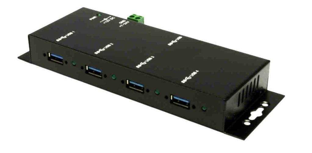
4 Deutsch 3. Aufbau, Anschlüsse & Jumper Einstellungen 3.1 Aufbau 1x USB 3.1 (Gen1) Upstream B-Buchse Betriebs LED 12V DC Anschluss für beiliegendes Netzteil 7-24V T-Block für optionales externes Netzteil 4x USB 3.1 (Gen1) Downstream A-Buchse Status LED für jeden Port 3.2 Anschlüsse +7V - 24V T-Block: ACHTUNG!!! Schließen Sie niemals Strom an Ground an, dadurch kann Ihre Hardware zerstört werden!!! +7V - 24V GND (Ground) 12V Buchse: ACHTUNG!!! Nur zur Verwendung mit im Lieferumfang enthaltenem Netzteil! 4
5 Deutsch 3. Aufbau, Anschlüsse & Jumper Einstellungen 3.2 Anschlüsse USB 3.1 (Gen1) A-Buchse: StdB_SSTX + StdB_SSTX - GND_DRAIN StdB_SSTX+ StdB_SSTX - Achtung! Stecker niemals umgekehrt oder mit Gewalt einstecken. VCC D- GND D+ USB 3.1 (Gen1) B-Buchse: GND_DRAIN StdB_SSTX + StdB_SSTX+ StdB_SSTX - StdB_SSTX - D- VBus D+ GND Achtung! Stecker niemals umgekehrt oder mit Gewalt einstecken. 5

6 Deutsch 3. Aufbau, Anschlüsse & Jumper Einstellungen 3.3 Jumper Einstellungen Der wird mit der Einstellung Bus-Power ausgeliefert. Sie haben aber die Möglichkeit den auf der Datenleitung zum PC sprich die USB B-Buchse stromlos zu machen. Dafür müssen Sie zu erst das Gehäuse mit den vier Schrauben auf den Seiten öffnen. Nun müssen Sie den Jumper JP1 von BUS (Bus-Powered) auf SELF (Self-Powered) setzen. Siehe nachfolgende Abbildung. SELF BUS JP1 6
7 Deutsch 4. Hardware Installation Beachten Sie bitte die folgenden Installationshinweise. Da es große Unterschiede zwischen PC s gibt, können wir Ihnen nur eine generelle Anleitung zum Einbau der EX- 1184HMV geben. Bei Unklarheiten halten Sie sich bitte an die Bedienungsanleitung Ihres Computersystems. 1. Verbinden Sie das mitgelieferte USB Kabel mit der USB B-Buchse des Hub s. 2. Schließen Sie jetzt den Stromanschluss des mitgelieferten Netzteils an den DC Anschluss des Hub s an oder verbinden Sie das optionale Netzteil mit dem Terminal Block des Hub s und stecken Sie den Netzstecker des Netzteils in eine Steckdose. 3. Verbinden Sie nun das andere Ende (A-Stecker) des mitgelieferten USB Kabels mit der A-Buchse an Ihrem PC. 5. Treiber Installation Alle Betriebssysteme Nach Abschluss der Hardwareinstallation erkennt das Betriebssystem den EX- 1184HMV automatisch und installiert diesen. ÜBERPRÜFEN DES INSTALLIERTEN TREIBER Öffnen Sie den >Geräte-Manager<. Jetzt müssten Sie unter USB-Controller folgende Einträge sehen: Sind diese oder ähnliche Einträge vorhanden, ist der USB Hub richtig installiert. 6. Reinigung Zur Reinigung des Gerätes verwenden Sie bitte ausschließlich ein trockenes nicht faserndes Tuch und entfernen Sie die Verschmutzung mit leichtem Druck. Im Bereich der Anschlüsse bitte darauf Achten, dass keine Fasern des Tuchs in der Buchse hinterlassen werden. Verwenden Sie bitte zu Reinigung in keinem Fall ein feuchtes oder nasses Tuch! 7
8 Deutsch 7. Technische Daten Chip-Set: Datentransfer-Rate: Anschlüsse: Genesys 5Gbit/s 4x USB 3.1(Gen1) A-Buchse, 1x USB 3.1(Gen1) B-Buchse 1x Terminal Block 7-24V, 1x 12V DC Anschluss Hardwaresystem: USB 1.1, 2.0, 3.0 & 3.1 Betriebssystem: Betriebstemperatur: Lagertemperatur: Alle Betriebssysteme 0 bis 55 Celsius -20 bis 85 Celsius Rel. Luftfeuchtigkeit: 5% bis 95% Stromversorgung: Abmessung: Gewicht: +7 bis +24 Volt & +12 Volt 178,40 x 58,50 x 24,11 mm 850g 8. Technische Zeichnung 8
9 English 1. Description The is a plug & play high-speed USB 3.1 (Gen1) metal hub for 4 USB devices. The provides 4 ports for USB devices and 1 uplink port for PC. It supports all USB connections from 1.1 to 3.1. All ports can fix with screw lock. Via a external power supply it is possible to provide a maximum of 900mA on each USB port. The design fully utilize the Genesys chipset, which represents the latest in SuperSpeed USB interface technology. It uses data transfer rates up to 5Gbit/s. It provides a secure and very high data transfer on each single port. The support the Self Powered and Bus Powered mode. Features: Compatible for USB 1.1, 2.0, 3.0 & 3.1 Up to 5Gbit/s All Operating Systems are supported All ports are Screw Lock Certificate for 2. Extent of Delivery Before you connect the to your PC, you should first check the contents of the delivery: Power Supply (12V/3A) USB 3.1 (Gen1) Cable (screw lock) Manual 9
 Upstream B-Port Power LED 12V DC Connector for included Power Supply 7-24V T-Block for optional external Power Supply 4x USB 3.1 (Gen1) Downstream A-Port Status LED for each Port 3.")
10 English 3. Layout, Connections & Jumper Settings 3.1 Layout 1x USB 3.1 (Gen1) Upstream B-Port Power LED 12V DC Connector for included Power Supply 7-24V T-Block for optional external Power Supply 4x USB 3.1 (Gen1) Downstream A-Port Status LED for each Port 3.2 Connections +7V - 24V T-Block: ATTENTION!! Never connect power to GND, it will destroy your Hardware!!! +7V - 24V GND (Ground) 12V Connector: ATTENTION!!! Use only with Power Supply which is included in delivery! 10
 A-Port: StdB_SSTX + StdB_SSTX - GND_DRAIN StdB_SSTX+ StdB_SSTX - Attention!")
 B-Port: GND_DRAIN StdB_SSTX + StdB_SSTX+ StdB_SSTX - StdB_SSTX - D- VBus Attention!")
11 English 3. Layout, Connections & Jumper Settings 3.2 Connections USB 3.1 (Gen1) A-Port: StdB_SSTX + StdB_SSTX - GND_DRAIN StdB_SSTX+ StdB_SSTX - Attention! Never plug in with force or in wrong direction. VCC D- GND D+ USB 3.1 (Gen1) B-Port: GND_DRAIN StdB_SSTX + StdB_SSTX+ StdB_SSTX - StdB_SSTX - D- VBus Attention! Never plug in with force or in wrong direction. D+ GND 11
12 English 3. Layout, Connections & Jumper Settings 3.3 Jumper Settings The will be delivered with the setting Bus-Power. But you have the possibility to cut the power at the data line. For this you open the case with the four screws on both sides. Then you must set the jumper JP1 from BUS (Bus-Powered) to SELF (Self-Powered). See the following picture. SELF BUS JP1 12

13 English 4. Hardware Installation Because there are large differences between PC s, we can give you only a general installation guide. Please refer your computer s reference manual whenever in doubt. Power LED 1. Connect the USB cable to the USB B-Port at the Hub. 2. Connect the included power supply to the DC connector at the hub or connect the optional power supply into the terminal block at the Hub. 3. Now connect the other end from the USB cable (A-Plug) to the A-Port at your PC. 5. Driver Installation All Operating Systems After the hardware installation the OS will recognize the device automatically and install the drivers. CHECK INSTALLED DRIVER Open the >Device manager<. Now you should see at USB-Controller the following new entry's: +7V - 24V T-Block: If you see this or a similar information the device is installed correctly. 6. Cleaning For cleaning please use only a dry fluff less cloth and remove the dirt with gently pressure. In the area of the connectors please make sure that no fibres from the cloth remain in the connectors. Attention! Never use a moist or wet cloth for cleaning! 13
 B-Port, 1x Terminal Block 7-24V, 1x 12V Connector Hardware System: USB 1.1, 2.0, 3.0 & 3.")
14 English 7. Technical Information Chip-Set: Data Transfer Rate: Connectors: Genesys 5Gbit/s 4x USB 3.1 (Gen1) A-Port, 1x USB 3.1 (Gen1) B-Port, 1x Terminal Block 7-24V, 1x 12V Connector Hardware System: USB 1.1, 2.0, 3.0 & 3.1 Operating System: Operating Temperature: Storage Temperature: All Operating Systems 32 F to 131 Fahrenheit -40 F to 185 Fahrenheit Rel. Humidity: 5% to 95% Power: Size: Weight: +7 bis +24 Volt & +12 Volt 178,40 x 58,50 x 24,11 mm 850g 8. Technical Drawing 14
15
EX-1163HM. 4 Port USB 2.0 Metall HUB für Trägerschiene. 4 Port USB 2.0 Metal HUB for Din-Rail. Anleitung. Manual
 Anleitung EX-1163HM 4 Port USB 2.0 Metall HUB für Trägerschiene 4 Port USB 2.0 Metal HUB for Din-Rail Manual EXSYS Vertriebs GmbH Industriestraße 8 61449 Steinbach (Taunus) Vers. 1.0 / 08.09.17 EX-1163HM
EX-1177HMVS. Anleitung. Manual. 7 Port USB 2.0 Metal HUB (DIN-Rail) mit 15KV ESD Überspannungsschutz. with 15KV ESD Surge Protection
 mit 15KV ESD Überspannungsschutz. with 15KV ESD Surge Protection") Anleitung 7 Port USB 2.0 Metall HUB (DIN-Rail) mit 15KV ESD Überspannungsschutz 7 Port USB 2.0 Metal HUB (DIN-Rail) with 15KV ESD Surge Protection Manual Vers. 1.0 / 16.02.18 Inhaltsverzeichnis 1. Beschreibung
Anleitung 7 Port USB 2.0 Metall HUB (DIN-Rail) mit 15KV ESD Überspannungsschutz 7 Port USB 2.0 Metal HUB (DIN-Rail) with 15KV ESD Surge Protection Manual Vers. 1.0 / 16.02.18 Inhaltsverzeichnis 1. Beschreibung
EX-1194HMS. Anleitung. Manual. 4 Port USB 3.1 (Gen1) Metall HUB mit 15KV ESD Überspannungsschutz
 Metall HUB mit 15KV ESD Überspannungsschutz") Anleitung EX-1194HMS 4 Port USB 3.1 (Gen1) Metall HUB mit 15KV ESD Überspannungsschutz 4 Port USB 3.1 (Gen1) Metal HUB with 15KV ESD Surge Protection Manual Vers. 1.1 / 19.09.18 EX-1194HMS Inhaltsverzeichnis
Anleitung EX-1194HMS 4 Port USB 3.1 (Gen1) Metall HUB mit 15KV ESD Überspannungsschutz 4 Port USB 3.1 (Gen1) Metal HUB with 15KV ESD Surge Protection Manual Vers. 1.1 / 19.09.18 EX-1194HMS Inhaltsverzeichnis
16 Port USB 3.1 (Gen1) Metall HUB mit 1,5A Strom pro Port und 15KV ESD Überspannungsschutz
 Metall HUB mit 1,5A Strom pro Port und 15KV ESD Überspannungsschutz") Anleitung 16 Port USB 3.1 (Gen1) Metall HUB mit 1,5A Strom pro Port und 15KV ESD Überspannungsschutz 16 Port USB 3.1 (Gen1) Metal HUB with 1,5A power for each port and 15KV ESD Surge Protection Manual
Anleitung 16 Port USB 3.1 (Gen1) Metall HUB mit 1,5A Strom pro Port und 15KV ESD Überspannungsschutz 16 Port USB 3.1 (Gen1) Metal HUB with 1,5A power for each port and 15KV ESD Surge Protection Manual
Anleitung EX-1316HMV. USB 2.0 zu 16x RS-232 Ports im Metallgehäuse. USB 2.0 to 16x RS-232 Ports Metal Case. Vers. 1.0 /
 Anleitung EX-1316HMV USB 2.0 zu 16x RS-232 Ports im Metallgehäuse USB 2.0 to 16x RS-232 Ports Metal Case Manual Vers. 1.0 / 08.12.17 EX-1316HMV Inhaltsverzeichnis 1. Beschreibung 3 2. Lieferumfang 3 3.
Anleitung EX USB 3.1 (Gen1) zu 4 Port Gigabit Ethernet. USB 3.1 (Gen1) to 4 Port Gigabit Ethernet. Vers. 1.2 /
 zu 4 Port Gigabit Ethernet. USB 3.1 (Gen1) to 4 Port Gigabit Ethernet. Vers. 1.2 /") Anleitung USB 3.1 (Gen1) zu 4 Port Gigabit Ethernet USB 3.1 (Gen1) to 4 Port Gigabit Ethernet Manual Vers. 1.2 / 20.02.18 Inhaltsverzeichnis 1. Beschreibung 3 2. Lieferumfang 3 3. Aufbau, Anschlüsse &
Anleitung USB 3.1 (Gen1) zu 4 Port Gigabit Ethernet USB 3.1 (Gen1) to 4 Port Gigabit Ethernet Manual Vers. 1.2 / 20.02.18 Inhaltsverzeichnis 1. Beschreibung 3 2. Lieferumfang 3 3. Aufbau, Anschlüsse &
EX-1330M. USB 3.1 (Gen1) zu 4 Port Gigabit Ethernet Metall Gehäuse. USB 3.1 (Gen1) to 4 Port Gigabit Ethernet Metal Case. Anleitung.
 zu 4 Port Gigabit Ethernet Metall Gehäuse. USB 3.1 (Gen1) to 4 Port Gigabit Ethernet Metal Case. Anleitung.") Anleitung USB 3.1 (Gen1) zu 4 Port Gigabit Ethernet Metall Gehäuse USB 3.1 (Gen1) to 4 Port Gigabit Ethernet Metal Case Manual Vers. 1.0 / 19.02.18 Inhaltsverzeichnis 1. Beschreibung 3 2. Lieferumfang
Anleitung USB 3.1 (Gen1) zu 4 Port Gigabit Ethernet Metall Gehäuse USB 3.1 (Gen1) to 4 Port Gigabit Ethernet Metal Case Manual Vers. 1.0 / 19.02.18 Inhaltsverzeichnis 1. Beschreibung 3 2. Lieferumfang
USB -> Seriell Adapterkabel Benutzerhandbuch
 USB -> Seriell Adapterkabel Benutzerhandbuch 1. Produkt Eigenschaften 1 2. System Vorraussetzungen 1 3. Treiber Installation (Alle Windows Systeme) 1 4. Den COM Port ändern 2 5. Einstellen eines RS232
EX-1339HMV EX-1339HMVS
 Vers. 1.0 / 10.11.14 Bedienungsanleitung EX-1339HMV EX-1339HMVS 8x zu USB 2.0 Manual Inhaltsverzeichnis 1. Beschreibung 3 2. Lieferumfang 3 3. Aufbau und Anschlüsse 4-5 3.1 Aufbau 4 3.2 Anschlüsse 5 4.
AKTIVE DVB-T ZIMMERANTENNE ANSCHLUSSHINWEISE ACTIVE DVB-T INDOOR ANTENNA CONNECTION INSTRUCTIONS
 K la vi er l ac ko p tik AKTIVE DVB-T ZIMMERANTENNE ANSCHLUSSHINWEISE ACTIVE DVB-T INDOOR ANTENNA CONNECTION INSTRUCTIONS ZA 8970 DRUCKS0682.indd 1 05.09.12 15:15 VerpAckunGsinhAlT UKW / UHF / VHF Flachantenne
EX RS-232/422/485 PCI-E Karte mit 4 x 9 Pin Anschluss. Anleitung. Manual. 7. Technical Information. SystemBase SB16C1054PCI
 English 7. Technical Information Anleitung Chip-Set: Data Transfer Rate: Connectors: Hardware System: Operating System: Operating Temperature: SystemBase SB16C1054PCI 50 Baud up to 921.6 KBaud 1x 44 pin
PoE Kit Mounting Instructions SG/XG 210/230/310/330/430/450
 PoE Kit Mounting Instructions PoE Kit Mounting Instructions Please note ÌÌ Before installing/removing any LAN module please make sure that the appliance is powered off and power cables are removed. ÌÌ
iid software tools QuickStartGuide iid USB base driver installation
 iid software tools QuickStartGuide iid software tools USB base driver installation microsensys Nov 2016 Introduction / Einleitung This document describes in short form installation of the microsensys USB
EX Slot Box Zur Erweiterung um 2 PCI & 2 PCI-EXpress Anschlüsse
 Bedienungsanleitung 4 Slot Box Zur Erweiterung um 2 PCI & 2 PCI-EXpress Anschlüsse V1.1 18.03.13 Inhaltsverzeichnis 1. BESCHREIBUNG... 3 2. LAYOUT... 3 3. HARDWARE INSTALLATION... 4 4. ANSCHLUSSBEISPIEL...
EX Slot PCI Box Zur Erweiterung um 4 PCI Anschlüsse für ExpressCard
 Bedienungsanleitung EX-1015 4 Slot PCI Box Zur Erweiterung um 4 PCI Anschlüsse für ExpressCard V1.1 15.03.13 EX-1015 4 Slot PCI-Erweiterung Inhaltsverzeichnis 1. BESCHREIBUNG 3 2. LAYOUT 3 3. HARDWARE
EX PCI & 2 PCI-E
 Bedienungsanleitung EX-1041 2 PCI & 2 PCI-E Box Zur Erweiterung von 2 PCI & 2 PCI-Express Anschlüsse für lange Karten inklusive internem 220Watt Netzteil V1.3 18.12.13 EX-1041 2 PCI & 2 PCI-E Slot Erweiterung
Anleitung EX RS-232 PCI Karte mit 4 x 9 Pin Anschluss. Vers. 1.0 / Manual
 Anleitung RS-232 PCI Karte mit 4 x 9 Pin Anschluss Manual Vers. 1.0 / 01.10.15 Inhaltsverzeichnis 1. Beschreibung 3 2. Lieferumfang 3 3. Aufbau und Anschlüsse 4-5 3.1 Aufbau 4 3.2 Anschlüsse 4-5 4. Jumper
VN7640 FlexRay/CAN/LIN/Ethernet Interface Quick Start Guide. Version 1.1 English/Deutsch
 VN7640 FlexRay/CAN/LIN/Ethernet Interface Quick Start Guide Version 1.1 English/Deutsch Quick Start Guide VN7640 ENGLISH 1 ENGLISH 1.1 Installation Step by Step Procedure Please use the drivers from the
EX Slot PCI Box Zur Erweiterung von 4 PCI Anschlüsse für lange Karten inklusive internem 220Watt Netzteil
 Bedienungsanleitung EX-1031 4 Slot PCI Box Zur Erweiterung von 4 PCI Anschlüsse für lange Karten inklusive internem 220Watt Netzteil V1.3 17.12.13 EX-1031 4 PCI Slot Erweiterung Inhaltsverzeichnis 1. BESCHREIBUNG
EX PCI & 2 PCI-E
 Bedienungsanleitung EX-1025 2 PCI & 2 PCI-E Box Zur Erweiterung von 2 PCI & 2 PCI-Express Anschlüsse V1.2 12.12.13 EX-1025 2 PCI & 2 PCI-E Slot Erweiterung Inhaltsverzeichnis 1. BESCHREIBUNG 3 2. LAYOUT
Bedienungsanleitung User Manual. PCMCIA Reader B1
 Bedienungsanleitung User Manual PCMCIA Reader B1 Einführung Introduction Vielen Dank, dass Sie sich für ein KOBIL Smart Card Terminal entschieden haben. Mit dem KOBIL PCMCIA Reader B1 haben Sie ein leistungsfähiges
1 Allgemeine Information
 1 Allgemeine Information ACHTUNG! Der Betriebsdruck der Klasse 867 ist 6 bar. Sollte der Druck Ihrer Versorgungsleitung höher als 6 bar sein, muss der Druck an der Versorgungseinheit der Nähmaschine auf
EX PCI & 2 PCI-E
 Bedienungsanleitung EX-1020 2 PCI & 2 PCI-E Box Zur Erweiterung von 2 PCI & 2 PCI-Express Anschlüsse V1.2 12.12.13 EX-1020 2 PCI & 2 PCI-E Slot Erweiterung Inhaltsverzeichnis 1. BESCHREIBUNG 3 2. LAYOUT
Anleitung EX Ethernet/IP zu 4x RS-232. Ethernet/IP to. Vers. 1.8 / Manual
 Anleitung Ethernet/IP zu 4x RS-232 Ethernet/IP to 4x RS-232 Manual Vers. 1.8 / 26.10.17 Inhaltsverzeichnis 1. Beschreibung 3 2. Lieferumfang 3 3. Aufbau, Anschlüsse & LED s 4-5 3.1 Aufbau 4 3.2 Anschlüsse
EX Slot PCI Box Zur Erweiterung um 4 PCI Anschlüsse für lange Karten inklusive internem 220Watt Netzteil
 Bedienungsanleitung EX-1031 4 Slot PCI Box Zur Erweiterung um 4 PCI Anschlüsse für lange Karten inklusive internem 220Watt Netzteil V1.1 18.03.13 EX-1031 4 Slot PCI-Erweiterung Inhaltsverzeichnis 1. BESCHREIBUNG
EX-1095 PCI-Express Karte Zum Anschluss an alle Erweiterungen von Exsys mit DVI ähnlichem Anschluss
 Bedienungsanleitung EX-1095 PCI-Express Karte Zum Anschluss an alle Erweiterungen von Exsys mit DVI ähnlichem Anschluss V1.2 26.02.14 EX-1095 Karte für PCI / PCI-E Erweiterungen Inhaltsverzeichnis 1. BESCHREIBUNG...
Anleitung zur Schnellinstallation TU3-SA 1.01
 Anleitung zur Schnellinstallation TU3-SA 1.01 Table of Contents Deutsch 1 1. Bevor Sie anfangen 1 2. Installation der Hardware 2 3. Zugriff auf die Festplatten des TU3-SA 4 Troubleshooting 5 Version 02.15.2011
Anleitung / User Manual
 3,5 USB HDD Enclosure Anleitung / User Manual Die Sicherung von Daten innerhalb der Festplatte ist nicht durch den Hersteller garantiert. Wir sind nicht verantwortlich für Datenverlust, fertigen Sie regelmäßig
EX RS-232/422/485 PCI Karte mit 4 x 9 Pin Anschluss. Bedienungsanleitung. Manual. 6. Driver Installation
 English 6. Driver Installation Vers. 1.0 / 18.11.1 Bedienungsanleitung Windows 98/ ME/ 000/ XP/ Vista/ 7/ 8/ Server 00x After starting Windows it recognizes a new PCI Controller and opens the hardware
LAN-Mini/R-485 Handbuch Manual
 LAN-Mini/R-485 Handbuch Manual - Konverter - steckbare Schraubklemme - LAN-Kabel - CD - Hutschienenclip Lieferumfang Shipment - converter - pluggable locking ring - LAN-cord - CD - DIN rail clip Optionales
I am starting on Page 4 and assuming that the person has DECODERPROGGRAMMER manual.
 I am starting on Page 4 and assuming that the person has DECODERPROGGRAMMER manual. If you already use the Digital Plus USB interface: Before you install the software for the decoder programmer, back up
EX-1096 ExpressCard Zum Anschluss an alle Erweiterungen von Exsys mit DVI ähnlichem Anschluss
 Bedienungsanleitung EX-1096 ExpressCard Zum Anschluss an alle Erweiterungen von Exsys mit DVI ähnlichem Anschluss V1.2 26.02.14 EX-1096 Karte für PCI / PCI-E Erweiterungen Inhaltsverzeichnis 1. BESCHREIBUNG...
TOUCH CONTROL GLASS RGB DMX
 Bedienungsanleitung User s Manual Eigenschaften DMX 512 Stand Alone Controller mit Glasoberfläche Kompatibel mit allen DMX Einheiten oder DMX LED Geräten Betriebsbereit (vorprogrammiert mit 8 Szenen und
EX RS-232/422/485 PCI Karte mit 8 x 9 Pin Anschluss. Bedienungsanleitung. Manual. 6. Driver Installation
 English 6. Driver Installation Vers. 1.0 / 19.11.14 Bedienungsanleitung Windows 98/ ME/ 2000/ XP/ Vista/ 7/ 8/ Server 200x After starting Windows it recognizes a new PCI Controller and opens the hardware
ITAC Bedienungsanleitung User manual. Originalbedienungsanleitung in deutscher Sprache. Für künftige Verwendung aufbewahren.
 D Bedienungsanleitung User manual Originalbedienungsanleitung in deutscher Sprache. Für künftige Verwendung aufbewahren. This user manual contains important information for installation and operation.
Tilt Wall. Montage- und Gebrauchsanleitung. Assembly instructions and manual.
 Tilt Wall Montage- und Gebrauchsanleitung Assembly instructions and manual www.nyta.eu Montagehinweise & Begriffserklärung Assembly direction and glossary Vor der Montage alle stromführenden Leitungen
Anleitung EX RS-232 PCI Karte mit 16 x 9 Pin Anschluss. Vers. 1.1 / Manual
 Anleitung RS-232 PCI Karte mit 16 x 9 Pin Anschluss Manual Vers. 1.1 / 07.02.17 Inhaltsverzeichnis 1. Beschreibung 3 2. Lieferumfang 3 3. Aufbau und Anschlüsse 4-5 3.1 Aufbau 4 3.2 Anschlüsse 4-5 4. Jumper
EL-21SY. 2 in, 1 out v1.3 HDMI Switcher OPERATION MANUAL
 EL-21SY 2 in, 1 out v1.3 HDMI Switcher OPERATION MANUAL Table of Contents 1. Introduction 1 2. Features 1 3. Package Contents 1 4. Operation Controls and Functions 2 4.1 Front Panel Diagram 2 4.2 Rear
EX-1095 PCI-Express Karte Zum Anschluss an alle Erweiterungen von Exsys mit DVI ähnlichem Anschluss
 Bedienungsanleitung EX-1095 PCI-Express Karte Zum Anschluss an alle Erweiterungen von Exsys mit DVI ähnlichem Anschluss V1.1 18.03.13 EX-1095 Karte für PCI-Erweiterungen Inhaltsverzeichnis 1. BESCHREIBUNG...
GmbH, Stettiner Str. 38, D-33106 Paderborn
 Serial Device Server Der Serial Device Server konvertiert die physikalische Schnittstelle Ethernet 10BaseT zu RS232C und das Protokoll TCP/IP zu dem seriellen V24-Protokoll. Damit können auf einfachste
INDEX. 3. Package Contents Connection and Operation...4
 3 - P O R T H D M I S w i t c h V i s i o n 3 3 2 7 0 3 INDEX 1. I n t r o d u c t i o n... 2 2. S p e c i f i c a t i o n s... 3 3. Package Contents...3 4. P a n e l D e s c r i p t i o n s.. 4 5. Connection
Softwareupdate-Anleitung // Porty L 600 / Porty L 1200
 Softwareupdate-Anleitung // Porty L 600 / Porty L 1200 1 Softwareupdate-Anleitung // Porty L 600 / Porty L 1200 HENSEL-VISIT GmbH & Co. KG Robert-Bunsen-Str. 3 D-97076 Würzburg-Lengfeld GERMANY Tel./Phone:
Konfiguration von eduroam. Configuring eduroam
 eduroam Windows 8.1 / 10 Konfiguration von eduroam Configuring eduroam 08.10.2018 kim.uni-hohenheim.de kim@uni-hohenheim.de Wissenschaftliche Einrichtungen und Universitäten bieten einen weltweiten Internetzugang
PROFIBUS-DP Repeater 1 to 1 and 1 to 5 with optional level converter module
 LSS PROFIBUS-DP Repeater 1 to 1 and 1 to 5 with optional level converter module The LSS PROFIBUS-DP repeaters 1 to 1 and 1 to 5 are used for coupling up to six PROFIBUS bus segments in RS 485 bus technology.
miditech 4merge 4-fach MIDI Merger mit :
 miditech 4merge 4-fach MIDI Merger mit : 4 x MIDI Input Port, 4 LEDs für MIDI In Signale 1 x MIDI Output Port MIDI USB Port, auch für USB Power Adapter Power LED und LOGO LEDs Hochwertiges Aluminium Gehäuse
Anleitung. EX-6031 / EX-6031PoE. Ethernet/IP zu 1x RS-232. Ethernet/IP to. Vers. 1.0 / Manual
 Anleitung EX-6031 / EX-6031PoE Ethernet/IP zu 1x RS-232 Ethernet/IP to 1x RS-232 Manual Vers. 1.0 / 26.10.17 EX-6031 / EX-6031PoE Inhaltsverzeichnis 1. Beschreibung 3 2. Lieferumfang 3 3. Aufbau, Anschlüsse
Anleitung zur Schnellinstallation TFM-561U
 Anleitung zur Schnellinstallation TFM-561U V1 Table of Contents Deutsch 1 1. Bevor Sie anfangen 1 2. Installation 2 Troubleshooting 5 Version 08.25.2010 1. Bevor Sie anfangen Packungsinhalt TFM-561U Treiber
Wandarm inkl. Montagebox und Netzteil Wall bracket incl. installation box and power supply
 Wandarm inkl. Montagebox und Netzteil Wall bracket incl. installation box and power supply Beschreibung und technische Daten: Wandarm (IP-66) mit Montagebox und eingebautem Netzteil Passend für SANTEC
Anleitung zur Schnellinstallation TBW-107UB 1.01
 Anleitung zur Schnellinstallation TBW-107UB 1.01 Table of Contents Deutsch 1 1. Bevor Sie anfangen 1 2. Installation 2 3. Konfiguration des Bluetooth-Adapters 5 Troubleshooting 7 Version 02.25.2010 1.
esense Compatibility Information
 esense Compatibility Information Last Update July 2017 ios devices compatible with esense Apple iphone 4S or higher Apple ipad (from 2 nd generation) Apple ipod touch 5 th generation or higher Important
IR RECEIVER Bedienungsanleitung User s Manual
 Bedienungsanleitung User s Manual Die zweite Generation des MBNLED RGB DMX POWER SUPPLY und des MBNLED PRO Controller RGB DMX bieten die Möglichkeit, LED Module über eine Infrarot Fernbedienung zu steuern.
Anleitung EX SATA 2 / 3 Umschalter für bis zu 4 HDD s oder SSD s. Vers. 1.3 /
 Anleitung EX-3465 SATA 2 / 3 Umschalter für bis zu 4 HDD s oder SSD s Vers. 1.3 / 02.11.15 Inhaltsverzeichnis 1. BESCHREIBUNG 3 2. AUFBAU 3 3. HARDWARE INSTALLATION 4 3.1 Hardwareinstallation 4 3.2 Hot
EMCO Installationsanleitung / Installation instructions
 EMCO Installationsanleitung / Installation instructions Installationsanleitung Installation instructions Digitalanzeige digital display C40, FB450 L, FB600 L, EM 14D/17D/20D Ausgabe / Edition B 2012-03
A VGA monitor of the highest resolution that you will be using on any computer in the installation A PS/2 Keyboard A PS/2 Mouse
 PS/2 KVM SWITCH 2-PORT Vision 331217 Requirements Console A VGA monitor of the highest resolution that you will be using on any computer in the installation A PS/2 Keyboard A PS/2 Mouse Computers The following
ITAC Bedienungsanleitung User manual. Originalbedienungsanleitung in deutscher Sprache. Für künftige Verwendung aufbewahren.
 D Bedienungsanleitung User manual Originalbedienungsanleitung in deutscher Sprache. Für künftige Verwendung aufbewahren. This user manual contains important information for installation and operation.
UNIGATE CL Konfiguration mit WINGATE
 UNIGATE CL Konfiguration mit WINGATE - UNIGATE CL Configuration via WINGATE Art.-Nr.: V3928 Deutschmann Automation GmbH & Co. KG Carl-Zeiss-Str. 8 D-65520 Bad Camberg Phone: +49-(0)6434-9433-0 Hotline:
How-To-Do. Hardware Configuration of the CC03 via SIMATIC Manager from Siemens
 How-To-Do Hardware Configuration of the CC03 via SIMATIC Manager from Siemens Content Hardware Configuration of the CC03 via SIMATIC Manager from Siemens... 1 1 General... 2 1.1 Information... 2 1.2 Reference...
Bedienungsanleitung Thermodrucker User Manual Thermal printer
 Bedienungsanleitung Thermodrucker User Manual Thermal printer für/for NANOCOLOR UV / VIS II NANOCOLOR VIS II Inhalt 1. Vorwort... 3 2. Lieferumfang... 3 3. Technische Daten... 3 4. Bedienelemente... 3
Externes 2,5 -Festplattengehäuse USB 2.0 (6,35 cm)
") Externes 2,5 -Festplattengehäuse USB 2.0 (6,35 cm) Benutzerhandbuch DA-71001 DA-71002 Vorwort Herzlichen Glückwunsch zum Erwerb dieses Artikels! Lernen Sie eine neue Art der Datenspeicherung kennen. Es
Externes 2,5 -Festplattengehäuse USB 2.0 (6,35 cm) Benutzerhandbuch DA-71001 DA-71002 Vorwort Herzlichen Glückwunsch zum Erwerb dieses Artikels! Lernen Sie eine neue Art der Datenspeicherung kennen. Es
USB-A ANSCHLUSSKABEL CONNECTION CABLE
 V 12.17-TG USB-A ANSCHLUSSKABEL CONNECTION CABLE ANLEITUNG MANUAL DE EN E-BIKE SCHEINWERFER MIT POWERBANK E-BIKE FRONT LIGHTS WITH POWERBANK M99 MINI PRO-25 Art. No. R-M99MINIP-K-MBLK Gleiche Installation
Einbausatz Hub montieren
 Einbausatz Hub montieren Die Hub-Halterung bietet Platz für zwei Hubs. Es können nur Hubs eingebaut werden, die über den Konfigurator bzw. Rack-Architekt bestellbar sind. Der Lieferumfang besteht im Grundausbau
DRU-4H 4-Port. Universeller serieller Bus. Benutzerhandbuch
 DRU-4H 4-Port Universeller serieller Bus Benutzerhandbuch FCC Warnung Dieses Gerät hat in Tests die Grenzwerte eingehalten, die im Abschnitt 15 der FCC-Bestimmungen für digitale Geräte der Klasse B festgeschrieben
Lithium Fotoakku Ladeset Lithium Photo rechargeable battery Set
 Lithium Fotoakku Ladeset Lithium Photo rechargeable battery Set Technische Daten technical features:: Eingangsspannung: 100-240V AC Input Voltage: 100-240V AC Ausgangsspannung: 3,85V / 7,3V DC Output Voltage:
BRUUDT Kennzeichenhalter für die Honda NC750X ab 2016 BRUUDT Tail Tidy for the Honda NC750X 2016 and onwards.
 Montageanleitung Mounting instructions BRUUDT Kennzeichenhalter für die Honda NC750X ab 2016 BRUUDT Tail Tidy for the Honda NC750X 2016 and onwards. Noch einmal vielen Dank, dass Sie sich für unsere Produkte
Anleitung zur Schnellinstallation TFM-PCIV92A B1.21
 Anleitung zur Schnellinstallation TFM-PCIV92A B1.21 Table of Contents Deutsch 1 1. Bevor Sie anfangen 1 2. Installation 2 Troubleshooting 6 Version 05.11.2011 1. Bevor Sie anfangen Packungsinhalt ŸTFM-PCIV92A
Der Adapter Z250I / Z270I lässt sich auf folgenden Betriebssystemen installieren:
 Installationshinweise Z250I / Z270I Adapter IR USB Installation hints Z250I / Z270I Adapter IR USB 06/07 (Laden Sie den Treiber vom WEB, entpacken Sie ihn in ein leeres Verzeichnis und geben Sie dieses
Anleitung zur Schnellinstallation TU3-S
 Anleitung zur Schnellinstallation TU3-S25 1.01 Table of Contents Deutsch 1 1. Bevor Sie anfangen 1 2. Installation der Hardware 2 3. Zugriff auf die Speichergeräte im TU3-S25 4 Troubleshooting 5 Version
Installation Instructions
 EN DE Installation Instructions WLAN Installation Kit, 300 Mbps, 5 GHz, 16 dbi AK-4 Wireless Kit Scope of delivery Junction box AK-4 (1x) 1 Connection board AK-4 CB with 12VDC power supply unit (1x) 2
Anleitung zur Schnellinstallation TU2-HDMI 1.01
 Anleitung zur Schnellinstallation TU2-HDMI 1.01 Table of Contents Deutsch 1 1. Bevor Sie anfangen 1 2. Installationl 2 3. Konfiguration der Anzeigeeinstellungen 4 Troubleshooting 6 Version 02.16.2011 1.
Produktinformation _185PNdeen
 Produktinformation 201407_185PNdeen Solldaten-UPGRADE Juli 2014 WA 900 / 920 / 020 / 950 / 970 CURA S 800 / 860 / 060 / 900 / 960 WAB01 / WAB 02 CCT CURA R1200 / CURA R2000/ API R2000 BOSCH FWA 51x Auf
Anleitung EX Ethernet/IP zu 1x RS-232. Ethernet/IP to. Vers. 1.7 / Manual
 Anleitung Ethernet/IP zu 1x RS-232 Ethernet/IP to 1x RS-232 Manual Vers. 1.7 / 19.10.17 Inhaltsverzeichnis 1. Beschreibung 3 2. Lieferumfang 3 3. Aufbau, Anschlüsse & LED s 4-5 3.1 Aufbau 4 3.2 Anschlüsse
Installation Guide WLAN Interface
 Installation Guide 7106 7206 7010 WLAN Interface EN Installation Guide This guide explains how to install the Ethernet LAN card in your label printer. You should conult your dealer or distributor for more
AU-D2. Coaxial/Optical Audio Converter OPERATION MANUAL
 AU-D2 Coaxial/Optical Audio Converter OPERATION MANUAL Table of Contents 1. Introduction 1 2. Features 1 3. Operation Controls and Functions 2 3.1 Input Panel Diagram 2 3.2 Output Panel Diagram 2 3.3 Switcher
JX3-PS1. Installationsanleitung. Version Lieferumfang
 JX3-PS1 Spannungsversorgungsmodul Jetter AG Kontakte: Gräterstraße 2 E-Mail - Vertrieb: sales@jetter.de D-71642 Ludwigsburg E-Mail - Hotline: hotline@jetter.de Germany Telefon - Hotline: +49(0)7141/2550-444
Hama GmbH & Co KG Postfach Monheim/Germany Tel. +49 (0)9091/502-0 Fax +49 (0)9091/
9091/502-0 Fax +49 (0)9091/") www.hama.de Hama GmbH & Co KG Postfach 80 86651 Monheim/Germany Tel. +49 (0)9091/502-0 Fax +49 (0)9091/502-274 hama@hama.de www.hama.de 00062249-05.05 Multimedia Kit für/for Mercedes Command 2.0 00062249
www.hama.de Hama GmbH & Co KG Postfach 80 86651 Monheim/Germany Tel. +49 (0)9091/502-0 Fax +49 (0)9091/502-274 hama@hama.de www.hama.de 00062249-05.05 Multimedia Kit für/for Mercedes Command 2.0 00062249
Table of Cont 6. 2 General Information... 4 Purpose...4 Documentation...4 Scope of Supply...5 Technical Data Safety Regulations...
 2 General Information........................ 4 Purpose........................................4 Documentation................................4 Scope of Supply................................5 Technical
IDE zu USB2.0 Externes Festplatten - Gehäuse 2,5 (DA ) BEDIENUNGSANLEITUNG
 BEDIENUNGSANLEITUNG") IDE zu USB2.0 Externes Festplatten - Gehäuse 2,5 (DA-70550-1) BEDIENUNGSANLEITUNG I. Vorwort Herzlichen Glückwunsch zum Kauf dieses Produkts! Wir zeigen Ihnen ein neues Speicherkonzept mit einfacher Bedienung
IDE zu USB2.0 Externes Festplatten - Gehäuse 2,5 (DA-70550-1) BEDIENUNGSANLEITUNG I. Vorwort Herzlichen Glückwunsch zum Kauf dieses Produkts! Wir zeigen Ihnen ein neues Speicherkonzept mit einfacher Bedienung
LAN Modules Mounting Instructions SG/XG 210/230/310/330/430/450
 LAN Modules Mounting Instructions LAN Modules Mounting Instructions 1. 2. 3. 4. Please note Before installing/removing any LAN module please make sure that the appliance is powered off and power cables
Analog GSM-Gateway TRF
 Analog GSM-Gateway TRF GSM gateway for voice- or fax transmission 1 2009 com.sat GmbH Kommunikationssysteme Schwetzinger Str. 19 D-68519 Viernheim www.comsat.de Tel: +49-(0)180-3-768837 The connecting
Power Supply ND Series. USER MANUAL BEDIENUNGSANLEITUNG
 Power Supply ND Series USER MANUAL BEDIENUNGSANLEITUNG www.biontechnologies.com USER MANUAL Power Supply ND Series Safety Instructions Devices must be installed by qualified personnel in compliance with
Einführung...2 Überblick über die Technologie... 2 Über den 7 Port DRU-H7 USB Hub 3 Leistungsmerkmale des Produktes...4
 Inhaltsverzeichnis Einführung....2 Überblick über die Technologie... 2 Über den 7 Port DRU-H7 USB Hub 3 Leistungsmerkmale des Produktes...4 Installation..4 Beschreibung des Aussehens 5 Hardware-Installation6.6
Zusatz zur Betriebsanleitung Addendum to the Operating Instructions
 Drive Technology \ Drive Automation \ System Integration \ Services Zusatz zur Betriebsanleitung Addendum to the Operating Instructions Austausch von MOVIGEAR -S01 durch MOVIGEAR -DSC-B Replacing MOVIGEAR
Karten aktualisieren Don t Panik
 Karten aktualisieren Don t Panik 1. Starten Sie Ihr Gerät und schalten Sie das Navigationsprogramm ein. 2. Klicken Sie auf das "Menü": 3. Klicken Sie anschließend auf "Einstellungen": 4. Bewegen Sie den
FOX-150/E... FOX-350/E Solar Laderegler
 FOX-150/E... FOX-350/E Solar Laderegler Solar Charge Regulator Einbauanleitung mounting guidelines Einbauanleitung Diese Anleitung ist eine Ergänzung zu folgenden Installationsanleitungen: D "FOX-150
USB-C Multiport Adapter
 USB-C Multiport Adapter User Guide English USB-C Multiport Adapter Unlock the full potential of your Apple MacBook MINIX s USB-C Multiport Adapter is the world s most advanced USB-C adapter, delivering
EINBAUHINWEISE INSTALLATION INSTRUCTIONS
 EINBAUHINWEISE INSTALLATION INSTRUCTIONS FÜR JEDEN ANSPRUCH DAS RICHTIGE FAHRWERK. KW automotive GmbH Aspachweg 14 74427 Fichtenberg Telefon: +49 7971 9630-0 Telefax: +49 7971 9630-191 www.kwsuspensions.de
Walter Buchmayr Ges.m.b.H.
 Seite 1/10 Chapter Description Page 1 Advantages 3 2 Performance description 4 3 Settings 5 4 Options 6 5 Technical data 7 6 Pictures 8 http://members.aon.at/buchmayrgmbh e-mail: walter.buchmayr.gmbh@aon.at
USB 3.0 Externes Festplattengehäuse 3,5" (8,89 cm)
") USB 3.0 Externes Festplattengehäuse 3,5" (8,89 cm) Benutzerhandbuch DA-71035 Vorwort Herzlichen Glückwunsch zum Erwerb dieses Artikels! Lernen Sie eine neue Art der Datenspeicherung kennen. Es ist uns
USB 3.0 Externes Festplattengehäuse 3,5" (8,89 cm) Benutzerhandbuch DA-71035 Vorwort Herzlichen Glückwunsch zum Erwerb dieses Artikels! Lernen Sie eine neue Art der Datenspeicherung kennen. Es ist uns
LED Treiber: Anschlussschemata LED driver: connection diagrams
 ED Treiber: Anschlussschemata ED driver: connection diagrams TCI DC JOY MD für 18W ED (Konstantstromversorgung), 500mA, dimmbar via Phasenabschnittsdimmer / Taster (Push) 6Z 18 50 Sicherheitshinweise Montagehinweise
mobilcom-debitel SmartHome Schnell-Start-Anleitung Quick Start Guide
 mobilcom-debitel SmartHome Schnell-Start-Anleitung Quick Start Guide 1. Cube anschließen 1. Connect Cube n Schließen Sie den Cube an die Stromversorgung an. n Legen Sie die Batterien polungsrichtig in
ITAC Bedienungsanleitung User manual. Originalbedienungsanleitung in deutscher Sprache. Für künftige Verwendung aufbewahren.
 ITAC10100 D gb Bedienungsanleitung User manual Originalbedienungsanleitung in deutscher Sprache. Für künftige Verwendung aufbewahren. This user manual contains important information for installation and