Anleitung EX USB 3.1 (Gen1) zu 4 Port Gigabit Ethernet. USB 3.1 (Gen1) to 4 Port Gigabit Ethernet. Vers. 1.2 /
|
|
|
- Berndt Günther
- vor 5 Jahren
- Abrufe
Transkript


1 Anleitung USB 3.1 (Gen1) zu 4 Port Gigabit Ethernet USB 3.1 (Gen1) to 4 Port Gigabit Ethernet Manual Vers. 1.2 /
2 Inhaltsverzeichnis 1. Beschreibung 3 2. Lieferumfang 3 3. Aufbau, Anschlüsse & DIP-Schalter Aufbau Anschlüsse DIP-Schalter 6 4. Hardware Installation Treiber Installation Technische Daten 9 7. Technische Zeichnung 10 Index 1. Description Extent of Delivery Layout, Connections & DIP-Switch Layout Connections DIP-Switch Hardware Installation Driver Installation Technical Information Technical Drawing 18 2
3 Deutsch 1. Beschreibung Die ist mit einer USB 3.1 (Gen1) C-Buchse zum Anschluss an den PC und vier RJ45 Ports zum Anschluss für Endgeräte ausgestattet. Die ermöglicht Ihnen auf einfachste Weise Ihren Desktop PC oder Ihr Notebook in ein 10/100/1000Mbps Netzwerk einzubinden oder mehrere Endgeräte anzuschließen. Er unterstützt alle USB Anschlüsse von 1.1 bis 3.1. Die gewährleistet eine sichere Datenübertragung und exzellente Performance von bis zu 5Gbit pro Sekunde auf der USB Schnittstelle! Der RJ45 Anschluss wird durch einen Realtek Chipsatz unterstützt. Er unterstützt den Bus Power oder Self Power Modus. Im Lieferumfang ist eine Wandmontagehalterung und ein DIN-Rail Kit für die Installation auf einer Trägerschiene enthalten. Das DIN-Rail Kit wird mit vier Schrauben an der Wandmontagehalterung auf der Rückseite der festgeschraubt. Merkmale: Kompatibel zu USB 1.1, 2.0, 3.0 & 3.1 Bis zu 5Gbit/s Unterstützt: Windows XP/ Vista/ 7/ 8.x/ 10/ Server 20xx/ Linux 2.6.x & MAC OS 10.x Zertifiziert für 2. Lieferumfang Bevor Sie den an Ihren PC anschließen, überprüfen Sie bitte zuerst den Inhalt der Lieferung: EX USB 3.1 (Gen1) Kabel Wandmontagehalterung DIN-Rail Kit Anleitung 3
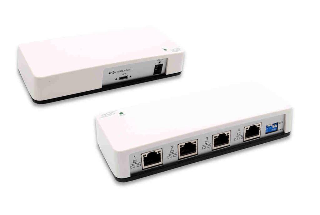
4 Deutsch 3. Aufbau, Anschlüsse & DIP-Schalter 3.1 Aufbau Vorderseite: Betriebs LED 4x RJ45 Anschluss DIP-Schalter Rückseite: 1x USB 3.1 (Gen1) Upstream C-Buchse 5V DC Anschluss für optionales Netzteil 4

 Mode USB 3.1 (Gen1) C-Buchse: Hinweis!")
5 Deutsch 3. Aufbau, Anschlüsse & DIP-Schalter 3.2 Anschlüsse RJ45 Anschluss: RJ45 Anschluss Pin Signal Pin Signal Pin Signal 1 BI_DA+ 4 BI_DC+ 7 BI_DD+ 2 BI_DA- 5 BI_DC- 8 BI_DD- 3 BI_DB+ 6 BI_DB- Status LED s: LED Name Farbe LED Funktion Link/Act Grün Ständig an: Blinken: Aus: Die Verbindung des Netzwerk Anschlusses ist am arbeiten und aktiv Überträgt Daten Netzwerk Anschluss ist getrennt Geschwindigkeit Gelb Aus: Ständig an: 10/100Mbps Mode Gigabit (1000Mbps) Mode USB 3.1 (Gen1) C-Buchse: Hinweis! Durch die Doppelbelegung der Pins, kann der USB Typ-C Stecker beidseitig in die Buchse gesteckt werden. 5 Volt Buchse: Achtung!!! Nur zur Verwendung mit optional erhältlichem Netzteil! 5
6 Deutsch 3. Aufbau, Anschlüsse & DIP-Schalter 3.3 DIP-Schalter DIP-Schalter Netzwerk Anschluss 1 Anschluss 1 2 Anschluss 2 3 Anschluss 3 4 Anschluss 4 DIP-Schalter Position OFF ON OFF ON OFF ON OFF ON Beschreibung Inaktiv* Aktiv* (Werkseinstellung) Inaktiv Aktiv (Werkseinstellung) Inaktiv Aktiv (Werkseinstellung) Inaktiv Aktiv (Werkseinstellung) Hinweis! *DIP-Schalter 1 steuert auch die OnBoard Windows Treiber. Wenn DIP-Schalter 1 aktiv ist, ist auch der Treiber aktiv. Andernfalls wenn der DIP-Schalter auf inaktiv gesetzt ist, werden auch die OnBoard Windows Treiber deaktiviert. 4. Hardware Installation Beachten Sie bitte die folgenden Installationshinweise. Da es große Unterschiede zwischen PC s gibt, können wir Ihnen nur eine generelle Anleitung zum Anschluss der EX geben. Bei Unklarheiten halten Sie sich bitte an die Bedienungsanleitung Ihres Computersystems. 1. Falls Sie die an einer Wand montieren möchten oder die auf einer Trägerschiene installieren wollen, befolgen Sie als erstes die Punkte 5, 6 & 7 auf Seite 7, bevor Sie mit Punkt 2 fortfahren. 2. Setzen Sie die DIP-Schalter 2, 3 & 4 auf inaktiv und nur den DIP-Schalter 1 auf aktiv und Verbinden Sie das mitgelieferte USB Kabel mit der USB C-Buchse des Hub s. 3. Schließen Sie jetzt den Stromanschluss des optionalen Netzteils an den DC Anschluss des Hub s an und stecken Sie den Netzstecker des Netzteils in eine Steckdose. 4. Verbinden Sie nun das andere Ende (A-Stecker) des mitgelieferten USB Kabels mit der A-Buchse an Ihrem PC. 6

7 Deutsch 4. Hardware Installation 5. Installieren Sie die zwei DIN-Rail Clips an der Wandmontagehalterung. Wandmontagehalterung Löcher für die Wandmontage Löcher für die Wandmontage DIN-Rail Clips 6. Anbringung der Wandmontagehalterung an der Unterseite der. 7. Installation der auf einer Trägerschiene. 7
8 Deutsch 5. Treiber Installation Alle Betriebssysteme Nach Abschluss der Hardwareinstallation müsste nun der DIP-Schalter 1 auf aktiv und DIP-Schalter 2, 3 & 4 auf inaktiv stehen und die mit dem PC verbunden sein. Die Stellung der DIP-Schalter ist aus diesem Grund wichtig, da das Betriebssystem die Ports nicht in der korrekten Reihenfolge installiert wenn alle DIP-Schalter auf aktiv gesetzt sind. 1. Der DIP-Schalter 1 steht auf Position ON und die DIP-Schalter 2, 3 & 4 stehen auf der Position OFF. 2. Die ist korrekt mittels dem mitgelieferten USB Kabel mit dem PC verbunden. 3. Jetzt können Sie Ihren PC starten. 4. Ihr Betriebssystem erkennt automatisch die und öffnet ebenfalls automatisch folgendes Fenster. 5. Jetzt führen Sie die Run RTK_NIC_DRIVER_INSTALLER.sfx.exe aus und folgen Sie den Anweisungen des Installationsmanager. 6. Nach erfolgreicher Installation wird der Netzwerk Anschluss 1 im Gerätemanager als Ethernet Port #1 angezeigt. 7. Nun setzen Sie den DIP-Schalter 2 auf die Position ON, während DIP-Schalter 3 & 4 auf Position OFF stehen bleiben. Das Betriebssystem installiert nun völlig automatisch den Netzwerk Anschluss 2 und dieser wird nun ebenfalls im Gerätemanager als Ethernet Port #2 angezeigt. Falls die Installation fehlschlägt, setzen Sie bitte den DIP-Switch wieder auf OFF und dann erneut auf ON! 8. Jetzt setzen Sie den DIP-Schalter 3 auf ON und der Anschluss 3 wird zugefügt. 9. Jetzt setzen Sie den DIP-Schalter 4 auf ON und der Anschluss 4 wird zugefügt. 8
9 Deutsch 5. Treiber Installation ÜBERPRÜFEN DES INSTALLIERTEN TREIBER Öffnen Sie den >Geräte-Manager<. Jetzt müssten Sie unter USB-Controller folgende Einträge sehen: Sind diese oder ähnliche Einträge vorhanden, ist die richtig installiert. 6. Technische Daten Chipsatz: Datentransfer-Rate: Anschlüsse: Realtek RTL8153B USB 3.0: bis zu 5Gbit/s Netzwerk: 10/100/1000Mbit/s 4x RJ45, 1x USB 3.1(Gen1) C-Buchse, 1x 5V DC Anschluss Hardwaresystem: USB 1.1, 2.0, 3.0 & 3.1 Betriebssystem: Betriebstemperatur: Lagertemperatur: Windows XP/ Vista/ 7/ 8.x/ 10/ Server 20xx/ Linux 2.6.x & MAC OS 10.x 0 bis 55 Celsius -40 bis 75 Celsius Rel. Luftfeuchtigkeit: 5% bis 95% Stromversorgung: Abmessung: Gewicht: +5 Volt 151,10 x 62,00 x 34,00 mm 300g 9
10 Deutsch 7. Technische Zeichnung 10
11 English 1. Description The provides one USB 3.1 (Gen1) C-Port for connection to PC and four RJ45 port. The gives you an easy way to integrate your desktop PC or notebook into a 10/100/1000Mbps network or to connect devices. It supports all USB connections from 1.1 to 3.1. It provides a secure and very high data transfer on the USB 3.1 (Gen1) interface. It uses data transfer rates up to 5Gbit/s! The RJ45 port is supported by an Realtek chipset. The support the Bus Powered or Self Powered mode. In the delivery is included a Wall Mounting Bracket and a DIN-Rail kit for installation in a 19 Rack. The DIN-Rail kit will be tightened with four screws to the Wall Mounting Bracket on the back of the. Features: Compatible for USB 1.1, 2.0, 3.0 & 3.1 Up to 5Gbit/s Supports: Windows XP/ Vista/ 7/ 8.x/ 10/ Server 20xx/ Linux 2.6.x & MAC OS 10.x Certificate for 2. Extent of Delivery Before you connect the to your PC, you should first check the contents of the delivery: EX USB 3.1 (Gen1) Cable Wall Mounting Kit DIN-Rail Kit Manual 11

12 English 3. Layout, Connections & DIP-Switch 3.1 Layout Front: Power LED 4x RJ45 Connector DIP-Switch Back: 1x USB 3.1 (Gen1) Upstream C-Port 5V DC Connector for optional Power Supply 12
13 English 3. Layout, Connections & DIP-Switch 3.2 Connections RJ45 Connector: RJ45 Connector Pin Signal Pin Signal Pin Signal 1 BI_DA+ 4 BI_DC+ 7 BI_DD+ 2 BI_DA- 5 BI_DC- 8 BI_DD- 3 BI_DB+ 6 BI_DB- Status LED s: LED Name Color LED Function Link/Act Green Steady on: Blinking: Off: The Connection on the Ethernet port is built and Active Transferring Ethernet Data Ethernet Port Disconnected Speed Yellow Off: Steady on: 10/100Mbps Mode Gigabit (1000Mbps) Mode USB 3.1 (Gen1) C-Port: Note! By dual assignment of the pins, the USB Type-C plug can be plugged into the port on both sides. 5 Volt Connector: ATTENTION!!! Use only with the optional power supply! 13
14 English 3. Layout, Connections & DIP-Switch 3.3 DIP-Switch DIP-Switch Ethernet Port 1 Port 1 2 Port 2 3 Port 3 Port 4 4 DIP-Switch Position OFF ON OFF ON OFF ON OFF ON Description Disabled* Enabled* (Factory Setting) Disabled Enabled (Factory Setting) Disabled Enabled (Factory Setting) Disabled Enabled (Factory Setting) Note! *DIP-Switch 1 controls the Onboard Windows Driver. If DIP-Switch 1 is enabled, then also the driver is enabled. Otherwise the DIP-Switch 1 is disabled, then also the driver is disabled. 4. Hardware Installation Because there are large differences between PC s, we can give you only a general installation guide. Please refer your computer s reference manual whenever in doubt. 1. If you want to install the on a wall or on a DIN-Rail, then please go ahead with the steps 5, 6 & 7 on page 15 before proceeding to step Set the DIP-Switches 2, 3 & 4 to disabled and only the DIP-Switch 1 to enabled and connect the included USB cable to the USB C-Port of the hub. 3. Connect the optional power supply to the DC connector at the hub. 4. Now connect the other end from the USB cable (A-Plug) to the A-Port at your PC. 14
15 English 4. Hardware Installation 5. Install the two DIN-Rail clips to the Wall Mounting. Wall Mounting Bracket Holes for Wall Mounting Holes for Wall Mounting DIN-Rail Clips 6. Assemble the Wall Mounting Bracket at the bottom of the. 7. Assemble the on the DIN-Rail. 15

16 English 5. Driver Installation All Operating Systems After completion of the hardware installation, the DIP-Switch 1 should be set to enabled and DIP-Switches 2, 3 & 4 to disabled and the should be connected to the PC. The position of the DIP-Switches is therefore important because the operating system does not install the ports in the correct order when all DIP-Switches are set to active at the same time. 1. The DIP-Switch 1 is set to ON and the DIP-Switches 2, 3 & 4 are set to OFF. 2. The is properly connected to the PC with the supplied USB cable. 3. Now you can start the PC. 4. Your operating system automatically detects the and opens the following window 5. Now run the Run RTK_NIC_DRIVER_INSTALLER.sfx.exe and follow the instructions of the installation manager. 6. After successful installation, the Ethernet Port 1 will be listed as Ethernet Port #1 in the device manager. 7. Now set the DIP-Switch 2 to ON, while the DIP-Switch 3 & 4 remain in the OFF position. The operating system will be install automatically the Ethernet Port 2 and it will be also listed as Ethernet Port #2 in the device manager. If the installation Fails, please reset the DIP-Switch to OFF and then set it to ON again! 8. Set DIP-Switch 3 to ON and the Ethernet Port 3 will be added to device manager. 9. Set DIP-Switch 4 to ON and the Ethernet Port 4 will be added to device manager. 16

17 English 5. Driver Installation CHECK INSTALLED DRIVER Open the >Device manager<. Now you should see at USB-Controller the following new entry's: If you see this or a similar information the is installed correctly. 6. Technical Information Chip-Set: Data Transfer Rate: Connectors: Realtek RTL8153B USB 3.0: up to 5Gbit/s Network: 10/100/1000Mbit/s 4x RJ45, 1x USB 3.1(Gen1) C-Port, 1x 5V DC Connector Hardware System: USB 1.1, 2.0, 3.0 & 3.1 Operating System: Operating Temperature: Storage Temperature: Rel. Humidity: 5% to 95% Power: Size: Weight: Windows XP/ Vista/ 7/ 8.x/ 10/ Server 20xx/ Linux 2.6.x & MAC OS 10.x 32 F to 131 Fahrenheit -40 F to 167 Fahrenheit +5 Volt 151,10 x 62,00 x 34,00 mm 300g 17
18 English 7. Technical Drawing 18
19
20
EX-1330M. USB 3.1 (Gen1) zu 4 Port Gigabit Ethernet Metall Gehäuse. USB 3.1 (Gen1) to 4 Port Gigabit Ethernet Metal Case. Anleitung.
 zu 4 Port Gigabit Ethernet Metall Gehäuse. USB 3.1 (Gen1) to 4 Port Gigabit Ethernet Metal Case. Anleitung.") Anleitung USB 3.1 (Gen1) zu 4 Port Gigabit Ethernet Metall Gehäuse USB 3.1 (Gen1) to 4 Port Gigabit Ethernet Metal Case Manual Vers. 1.0 / 19.02.18 Inhaltsverzeichnis 1. Beschreibung 3 2. Lieferumfang
Anleitung USB 3.1 (Gen1) zu 4 Port Gigabit Ethernet Metall Gehäuse USB 3.1 (Gen1) to 4 Port Gigabit Ethernet Metal Case Manual Vers. 1.0 / 19.02.18 Inhaltsverzeichnis 1. Beschreibung 3 2. Lieferumfang
EX-1163HM. 4 Port USB 2.0 Metall HUB für Trägerschiene. 4 Port USB 2.0 Metal HUB for Din-Rail. Anleitung. Manual
 Anleitung EX-1163HM 4 Port USB 2.0 Metall HUB für Trägerschiene 4 Port USB 2.0 Metal HUB for Din-Rail Manual EXSYS Vertriebs GmbH Industriestraße 8 61449 Steinbach (Taunus) Vers. 1.0 / 08.09.17 EX-1163HM
EX-1177HMVS. Anleitung. Manual. 7 Port USB 2.0 Metal HUB (DIN-Rail) mit 15KV ESD Überspannungsschutz. with 15KV ESD Surge Protection
 mit 15KV ESD Überspannungsschutz. with 15KV ESD Surge Protection") Anleitung 7 Port USB 2.0 Metall HUB (DIN-Rail) mit 15KV ESD Überspannungsschutz 7 Port USB 2.0 Metal HUB (DIN-Rail) with 15KV ESD Surge Protection Manual Vers. 1.0 / 16.02.18 Inhaltsverzeichnis 1. Beschreibung
Anleitung 7 Port USB 2.0 Metall HUB (DIN-Rail) mit 15KV ESD Überspannungsschutz 7 Port USB 2.0 Metal HUB (DIN-Rail) with 15KV ESD Surge Protection Manual Vers. 1.0 / 16.02.18 Inhaltsverzeichnis 1. Beschreibung
Anleitung EX-1184HMV. 4 Port USB 3.1 (Gen1) Metall HUB, verschraubbar. 4 Port USB 3.1 (Gen1) Metal HUB, screw lock. Vers. 1.0 /
 Metall HUB, verschraubbar. 4 Port USB 3.1 (Gen1) Metal HUB, screw lock. Vers. 1.0 /") Anleitung 4 Port USB 3.1 (Gen1) Metall HUB, verschraubbar 4 Port USB 3.1 (Gen1) Metal HUB, screw lock Manual Vers. 1.0 / 21.02.18 Inhaltsverzeichnis 1. Beschreibung 3 2. Lieferumfang 3 3. Aufbau, Anschlüsse
Anleitung 4 Port USB 3.1 (Gen1) Metall HUB, verschraubbar 4 Port USB 3.1 (Gen1) Metal HUB, screw lock Manual Vers. 1.0 / 21.02.18 Inhaltsverzeichnis 1. Beschreibung 3 2. Lieferumfang 3 3. Aufbau, Anschlüsse
EX-1194HMS. Anleitung. Manual. 4 Port USB 3.1 (Gen1) Metall HUB mit 15KV ESD Überspannungsschutz
 Metall HUB mit 15KV ESD Überspannungsschutz") Anleitung EX-1194HMS 4 Port USB 3.1 (Gen1) Metall HUB mit 15KV ESD Überspannungsschutz 4 Port USB 3.1 (Gen1) Metal HUB with 15KV ESD Surge Protection Manual Vers. 1.1 / 19.09.18 EX-1194HMS Inhaltsverzeichnis
Anleitung EX-1194HMS 4 Port USB 3.1 (Gen1) Metall HUB mit 15KV ESD Überspannungsschutz 4 Port USB 3.1 (Gen1) Metal HUB with 15KV ESD Surge Protection Manual Vers. 1.1 / 19.09.18 EX-1194HMS Inhaltsverzeichnis
16 Port USB 3.1 (Gen1) Metall HUB mit 1,5A Strom pro Port und 15KV ESD Überspannungsschutz
 Metall HUB mit 1,5A Strom pro Port und 15KV ESD Überspannungsschutz") Anleitung 16 Port USB 3.1 (Gen1) Metall HUB mit 1,5A Strom pro Port und 15KV ESD Überspannungsschutz 16 Port USB 3.1 (Gen1) Metal HUB with 1,5A power for each port and 15KV ESD Surge Protection Manual
Anleitung 16 Port USB 3.1 (Gen1) Metall HUB mit 1,5A Strom pro Port und 15KV ESD Überspannungsschutz 16 Port USB 3.1 (Gen1) Metal HUB with 1,5A power for each port and 15KV ESD Surge Protection Manual
Anleitung EX-1316HMV. USB 2.0 zu 16x RS-232 Ports im Metallgehäuse. USB 2.0 to 16x RS-232 Ports Metal Case. Vers. 1.0 /
 Anleitung EX-1316HMV USB 2.0 zu 16x RS-232 Ports im Metallgehäuse USB 2.0 to 16x RS-232 Ports Metal Case Manual Vers. 1.0 / 08.12.17 EX-1316HMV Inhaltsverzeichnis 1. Beschreibung 3 2. Lieferumfang 3 3.
USB -> Seriell Adapterkabel Benutzerhandbuch
 USB -> Seriell Adapterkabel Benutzerhandbuch 1. Produkt Eigenschaften 1 2. System Vorraussetzungen 1 3. Treiber Installation (Alle Windows Systeme) 1 4. Den COM Port ändern 2 5. Einstellen eines RS232
EX-1339HMV EX-1339HMVS
 Vers. 1.0 / 10.11.14 Bedienungsanleitung EX-1339HMV EX-1339HMVS 8x zu USB 2.0 Manual Inhaltsverzeichnis 1. Beschreibung 3 2. Lieferumfang 3 3. Aufbau und Anschlüsse 4-5 3.1 Aufbau 4 3.2 Anschlüsse 5 4.
Softwareupdate-Anleitung // Porty L 600 / Porty L 1200
 Softwareupdate-Anleitung // Porty L 600 / Porty L 1200 1 Softwareupdate-Anleitung // Porty L 600 / Porty L 1200 HENSEL-VISIT GmbH & Co. KG Robert-Bunsen-Str. 3 D-97076 Würzburg-Lengfeld GERMANY Tel./Phone:
ITAC Bedienungsanleitung User manual. Originalbedienungsanleitung in deutscher Sprache. Für künftige Verwendung aufbewahren.
 D Bedienungsanleitung User manual Originalbedienungsanleitung in deutscher Sprache. Für künftige Verwendung aufbewahren. This user manual contains important information for installation and operation.
EX RS-232/422/485 PCI-E Karte mit 4 x 9 Pin Anschluss. Anleitung. Manual. 7. Technical Information. SystemBase SB16C1054PCI
 English 7. Technical Information Anleitung Chip-Set: Data Transfer Rate: Connectors: Hardware System: Operating System: Operating Temperature: SystemBase SB16C1054PCI 50 Baud up to 921.6 KBaud 1x 44 pin
iid software tools QuickStartGuide iid USB base driver installation
 iid software tools QuickStartGuide iid software tools USB base driver installation microsensys Nov 2016 Introduction / Einleitung This document describes in short form installation of the microsensys USB
LAN-Mini/R-485 Handbuch Manual
 LAN-Mini/R-485 Handbuch Manual - Konverter - steckbare Schraubklemme - LAN-Kabel - CD - Hutschienenclip Lieferumfang Shipment - converter - pluggable locking ring - LAN-cord - CD - DIN rail clip Optionales
Anleitung EX Ethernet/IP zu 4x RS-232. Ethernet/IP to. Vers. 1.8 / Manual
 Anleitung Ethernet/IP zu 4x RS-232 Ethernet/IP to 4x RS-232 Manual Vers. 1.8 / 26.10.17 Inhaltsverzeichnis 1. Beschreibung 3 2. Lieferumfang 3 3. Aufbau, Anschlüsse & LED s 4-5 3.1 Aufbau 4 3.2 Anschlüsse
VN7640 FlexRay/CAN/LIN/Ethernet Interface Quick Start Guide. Version 1.1 English/Deutsch
 VN7640 FlexRay/CAN/LIN/Ethernet Interface Quick Start Guide Version 1.1 English/Deutsch Quick Start Guide VN7640 ENGLISH 1 ENGLISH 1.1 Installation Step by Step Procedure Please use the drivers from the
ITAC Bedienungsanleitung User manual. Originalbedienungsanleitung in deutscher Sprache. Für künftige Verwendung aufbewahren.
 D Bedienungsanleitung User manual Originalbedienungsanleitung in deutscher Sprache. Für künftige Verwendung aufbewahren. This user manual contains important information for installation and operation.
Anleitung zur Schnellinstallation TU3-SA 1.01
 Anleitung zur Schnellinstallation TU3-SA 1.01 Table of Contents Deutsch 1 1. Bevor Sie anfangen 1 2. Installation der Hardware 2 3. Zugriff auf die Festplatten des TU3-SA 4 Troubleshooting 5 Version 02.15.2011
TOUCH CONTROL GLASS RGB DMX
 Bedienungsanleitung User s Manual Eigenschaften DMX 512 Stand Alone Controller mit Glasoberfläche Kompatibel mit allen DMX Einheiten oder DMX LED Geräten Betriebsbereit (vorprogrammiert mit 8 Szenen und
Anleitung EX Ethernet/IP zu 1x RS-232. Ethernet/IP to. Vers. 1.7 / Manual
 Anleitung Ethernet/IP zu 1x RS-232 Ethernet/IP to 1x RS-232 Manual Vers. 1.7 / 19.10.17 Inhaltsverzeichnis 1. Beschreibung 3 2. Lieferumfang 3 3. Aufbau, Anschlüsse & LED s 4-5 3.1 Aufbau 4 3.2 Anschlüsse
Anleitung. EX-6031 / EX-6031PoE. Ethernet/IP zu 1x RS-232. Ethernet/IP to. Vers. 1.0 / Manual
 Anleitung EX-6031 / EX-6031PoE Ethernet/IP zu 1x RS-232 Ethernet/IP to 1x RS-232 Manual Vers. 1.0 / 26.10.17 EX-6031 / EX-6031PoE Inhaltsverzeichnis 1. Beschreibung 3 2. Lieferumfang 3 3. Aufbau, Anschlüsse
EL-21SY. 2 in, 1 out v1.3 HDMI Switcher OPERATION MANUAL
 EL-21SY 2 in, 1 out v1.3 HDMI Switcher OPERATION MANUAL Table of Contents 1. Introduction 1 2. Features 1 3. Package Contents 1 4. Operation Controls and Functions 2 4.1 Front Panel Diagram 2 4.2 Rear
Durametric. Installations Anleitung Quick Installation Guide. Deutsch: Seite 2 bis 3. English: Page 4 to 5. ww.fvd.de
 Durametric Quick Installation Guide Deutsch: Seite 2 bis 3 English: Page 4 to 5 w 2 Systemvoraussetzungen: Windows 7 / XP / Vista, (32- und 64-bit) - mind. 1.8GHz Dual Core Prozessor - 1 GB Arbeitsspeicher
EX PCI & 2 PCI-E
 Bedienungsanleitung EX-1041 2 PCI & 2 PCI-E Box Zur Erweiterung von 2 PCI & 2 PCI-Express Anschlüsse für lange Karten inklusive internem 220Watt Netzteil V1.3 18.12.13 EX-1041 2 PCI & 2 PCI-E Slot Erweiterung
Quick Guide Home Network Mode
 Quick Guide Home Network Mode English > 1 German > 3 About the Home Network Mode EN Tivizen Nano & iplug normally work on their own created networks (whose SSID starts with tivizentv or iplug ) in which
AU-D21. Digital Audio Optical Switcher OPERATION MANUAL
 AU-D21 Digital Audio Optical Switcher OPERATION MANUAL Table of Contents 1. Introduction 1 2. Features 1 3. Operation Controls and Functions 2 3.1 Front Panel Diagram 2 3.2 Rear Panel Diagram 2 3.3 Side
Bedienungsanleitung User Manual. PCMCIA Reader B1
 Bedienungsanleitung User Manual PCMCIA Reader B1 Einführung Introduction Vielen Dank, dass Sie sich für ein KOBIL Smart Card Terminal entschieden haben. Mit dem KOBIL PCMCIA Reader B1 haben Sie ein leistungsfähiges
EX Slot PCI Box Zur Erweiterung von 4 PCI Anschlüsse für lange Karten inklusive internem 220Watt Netzteil
 Bedienungsanleitung EX-1031 4 Slot PCI Box Zur Erweiterung von 4 PCI Anschlüsse für lange Karten inklusive internem 220Watt Netzteil V1.3 17.12.13 EX-1031 4 PCI Slot Erweiterung Inhaltsverzeichnis 1. BESCHREIBUNG
EX x RS-232 zu Ethernet / IP. Bedienungsanleitung. 7. Anschlüsse. 8. Technische Daten. Seriell 9 Pin D-SUB Stecker
 7. Anschlüsse Bedienungsanleitung Seriell 9 Pin D-SUB Stecker Pin Signal Pin Signal Pin Signal 1 DCD 4 DTR 7 RTS 2 RXD 5 GROUND 8 CTS 3 TXD 6 DSR 9 DB 9M EX-6034 8. Technische Daten Stromanschluss: 5V
G-FLASH OBD-TOOL ANLEITUNG FÜR BMW & AMG-MODELLE INSTALLATIONSSOFTWARE & VORBEREITUNG
 INSTALLATIONSSOFTWARE & VORBEREITUNG 1. Laden Sie die Installationssoftware für das G-POWER G-Flash OBD-Tool von diesem Link https://tinyurl.com/mygeniusclient auf Ihren Laptop / PC herunter und führen
Installation Instructions
 EN DE Installation Instructions WLAN Installation Kit, 300 Mbps, 5 GHz, 16 dbi AK-4 Wireless Kit Scope of delivery Junction box AK-4 (1x) 1 Connection board AK-4 CB with 12VDC power supply unit (1x) 2
EX Slot PCI Box Zur Erweiterung um 4 PCI Anschlüsse für ExpressCard
 Bedienungsanleitung EX-1015 4 Slot PCI Box Zur Erweiterung um 4 PCI Anschlüsse für ExpressCard V1.1 15.03.13 EX-1015 4 Slot PCI-Erweiterung Inhaltsverzeichnis 1. BESCHREIBUNG 3 2. LAYOUT 3 3. HARDWARE
EX PCI & 2 PCI-E
 Bedienungsanleitung EX-1025 2 PCI & 2 PCI-E Box Zur Erweiterung von 2 PCI & 2 PCI-Express Anschlüsse V1.2 12.12.13 EX-1025 2 PCI & 2 PCI-E Slot Erweiterung Inhaltsverzeichnis 1. BESCHREIBUNG 3 2. LAYOUT
mobilcom-debitel SmartHome Schnell-Start-Anleitung Quick Start Guide
 mobilcom-debitel SmartHome Schnell-Start-Anleitung Quick Start Guide 1. Cube anschließen 1. Connect Cube n Schließen Sie den Cube an die Stromversorgung an. n Legen Sie die Batterien polungsrichtig in
Anleitung zur Schnellinstallation TU3-S
 Anleitung zur Schnellinstallation TU3-S25 1.01 Table of Contents Deutsch 1 1. Bevor Sie anfangen 1 2. Installation der Hardware 2 3. Zugriff auf die Speichergeräte im TU3-S25 4 Troubleshooting 5 Version
AU-D2. Coaxial/Optical Audio Converter OPERATION MANUAL
 AU-D2 Coaxial/Optical Audio Converter OPERATION MANUAL Table of Contents 1. Introduction 1 2. Features 1 3. Operation Controls and Functions 2 3.1 Input Panel Diagram 2 3.2 Output Panel Diagram 2 3.3 Switcher
Softwareupdate-Anleitung // AC Porty L Netzteileinschub
 1 Softwareupdate-Anleitung // AC Porty L Netzteileinschub Softwareupdate-Anleitung // AC Porty L Netzteileinschub HENSEL-VISIT GmbH & Co. KG Robert-Bunsen-Str. 3 D-97076 Würzburg-Lengfeld GERMANY Tel./Phone:
Cameraserver mini. commissioning. Ihre Vision ist unsere Aufgabe
 Cameraserver mini commissioning Page 1 Cameraserver - commissioning Contents 1. Plug IN... 3 2. Turn ON... 3 3. Network configuration... 4 4. Client-Installation... 6 4.1 Desktop Client... 6 4.2 Silverlight
EX-1096 ExpressCard Zum Anschluss an alle Erweiterungen von Exsys mit DVI ähnlichem Anschluss
 Bedienungsanleitung EX-1096 ExpressCard Zum Anschluss an alle Erweiterungen von Exsys mit DVI ähnlichem Anschluss V1.2 26.02.14 EX-1096 Karte für PCI / PCI-E Erweiterungen Inhaltsverzeichnis 1. BESCHREIBUNG...
miditech 4merge 4-fach MIDI Merger mit :
 miditech 4merge 4-fach MIDI Merger mit : 4 x MIDI Input Port, 4 LEDs für MIDI In Signale 1 x MIDI Output Port MIDI USB Port, auch für USB Power Adapter Power LED und LOGO LEDs Hochwertiges Aluminium Gehäuse
Anleitung EX RS-232 PCI Karte mit 4 x 9 Pin Anschluss. Vers. 1.0 / Manual
 Anleitung RS-232 PCI Karte mit 4 x 9 Pin Anschluss Manual Vers. 1.0 / 01.10.15 Inhaltsverzeichnis 1. Beschreibung 3 2. Lieferumfang 3 3. Aufbau und Anschlüsse 4-5 3.1 Aufbau 4 3.2 Anschlüsse 4-5 4. Jumper
EX Slot PCI Box Zur Erweiterung um 4 PCI Anschlüsse für lange Karten inklusive internem 220Watt Netzteil
 Bedienungsanleitung EX-1031 4 Slot PCI Box Zur Erweiterung um 4 PCI Anschlüsse für lange Karten inklusive internem 220Watt Netzteil V1.1 18.03.13 EX-1031 4 Slot PCI-Erweiterung Inhaltsverzeichnis 1. BESCHREIBUNG
Anleitung zur Schnellinstallation TFM-561U
 Anleitung zur Schnellinstallation TFM-561U V1 Table of Contents Deutsch 1 1. Bevor Sie anfangen 1 2. Installation 2 Troubleshooting 5 Version 08.25.2010 1. Bevor Sie anfangen Packungsinhalt TFM-561U Treiber
EX RS-232/422/485 PCI Karte mit 8 x 9 Pin Anschluss. Bedienungsanleitung. Manual. 6. Driver Installation
 English 6. Driver Installation Vers. 1.0 / 19.11.14 Bedienungsanleitung Windows 98/ ME/ 2000/ XP/ Vista/ 7/ 8/ Server 200x After starting Windows it recognizes a new PCI Controller and opens the hardware
EX RS-232/422/485 PCI Karte mit 4 x 9 Pin Anschluss. Bedienungsanleitung. Manual. 6. Driver Installation
 English 6. Driver Installation Vers. 1.0 / 18.11.1 Bedienungsanleitung Windows 98/ ME/ 000/ XP/ Vista/ 7/ 8/ Server 00x After starting Windows it recognizes a new PCI Controller and opens the hardware
24-Port 10/100Mbps Web Smart PoE Switch with 4 Gigabit Ports and 2 Mini-GBIC Slots TPE-224WS
 24-Port 10/100Mbps Web Smart PoE Switch with 4 Gigabit Ports and 2 Mini-GBIC Slots TPE-224WS ŸAnleitung zur Schnellinstallation (1) ŸTroubleshooting (3) 1.12 1. Bevor Sie anfangen Packungsinhalt ŸTPE-224WS
EX Slot Box Zur Erweiterung um 2 PCI & 2 PCI-EXpress Anschlüsse
 Bedienungsanleitung 4 Slot Box Zur Erweiterung um 2 PCI & 2 PCI-EXpress Anschlüsse V1.1 18.03.13 Inhaltsverzeichnis 1. BESCHREIBUNG... 3 2. LAYOUT... 3 3. HARDWARE INSTALLATION... 4 4. ANSCHLUSSBEISPIEL...
Anleitung zur Schnellinstallation TFM-PCIV92A B1.21
 Anleitung zur Schnellinstallation TFM-PCIV92A B1.21 Table of Contents Deutsch 1 1. Bevor Sie anfangen 1 2. Installation 2 Troubleshooting 6 Version 05.11.2011 1. Bevor Sie anfangen Packungsinhalt ŸTFM-PCIV92A
PoE Kit Mounting Instructions SG/XG 210/230/310/330/430/450
 PoE Kit Mounting Instructions PoE Kit Mounting Instructions Please note ÌÌ Before installing/removing any LAN module please make sure that the appliance is powered off and power cables are removed. ÌÌ
IR RECEIVER Bedienungsanleitung User s Manual
 Bedienungsanleitung User s Manual Die zweite Generation des MBNLED RGB DMX POWER SUPPLY und des MBNLED PRO Controller RGB DMX bieten die Möglichkeit, LED Module über eine Infrarot Fernbedienung zu steuern.
Der Adapter Z250I / Z270I lässt sich auf folgenden Betriebssystemen installieren:
 Installationshinweise Z250I / Z270I Adapter IR USB Installation hints Z250I / Z270I Adapter IR USB 06/07 (Laden Sie den Treiber vom WEB, entpacken Sie ihn in ein leeres Verzeichnis und geben Sie dieses
Anleitung zur Schnellinstallation TBW-107UB 1.01
 Anleitung zur Schnellinstallation TBW-107UB 1.01 Table of Contents Deutsch 1 1. Bevor Sie anfangen 1 2. Installation 2 3. Konfiguration des Bluetooth-Adapters 5 Troubleshooting 7 Version 02.25.2010 1.
MANUAL_EN ANLEITUNG_DE PHONE SUITE SYNCHRONISATION SOFTWARE
 MANUAL_EN ANLEITUNG_DE PHONE SUITE SYNCHRONISATION SOFTWARE 2 PHONE SUITE MANUAL PHONE SUITE MANUAL 3 RESERVATION Technical Data is subject to change without notice. Changes, errors and misprints may not
How-To-Do. Hardware Configuration of the CC03 via SIMATIC Manager from Siemens
 How-To-Do Hardware Configuration of the CC03 via SIMATIC Manager from Siemens Content Hardware Configuration of the CC03 via SIMATIC Manager from Siemens... 1 1 General... 2 1.1 Information... 2 1.2 Reference...
AKTIVE DVB-T ZIMMERANTENNE ANSCHLUSSHINWEISE ACTIVE DVB-T INDOOR ANTENNA CONNECTION INSTRUCTIONS
 K la vi er l ac ko p tik AKTIVE DVB-T ZIMMERANTENNE ANSCHLUSSHINWEISE ACTIVE DVB-T INDOOR ANTENNA CONNECTION INSTRUCTIONS ZA 8970 DRUCKS0682.indd 1 05.09.12 15:15 VerpAckunGsinhAlT UKW / UHF / VHF Flachantenne
I am starting on Page 4 and assuming that the person has DECODERPROGGRAMMER manual.
 I am starting on Page 4 and assuming that the person has DECODERPROGGRAMMER manual. If you already use the Digital Plus USB interface: Before you install the software for the decoder programmer, back up
EX-1095 PCI-Express Karte Zum Anschluss an alle Erweiterungen von Exsys mit DVI ähnlichem Anschluss
 Bedienungsanleitung EX-1095 PCI-Express Karte Zum Anschluss an alle Erweiterungen von Exsys mit DVI ähnlichem Anschluss V1.2 26.02.14 EX-1095 Karte für PCI / PCI-E Erweiterungen Inhaltsverzeichnis 1. BESCHREIBUNG...
EX PCI & 2 PCI-E
 Bedienungsanleitung EX-1020 2 PCI & 2 PCI-E Box Zur Erweiterung von 2 PCI & 2 PCI-Express Anschlüsse V1.2 12.12.13 EX-1020 2 PCI & 2 PCI-E Slot Erweiterung Inhaltsverzeichnis 1. BESCHREIBUNG 3 2. LAYOUT
1 Allgemeine Information
 1 Allgemeine Information ACHTUNG! Der Betriebsdruck der Klasse 867 ist 6 bar. Sollte der Druck Ihrer Versorgungsleitung höher als 6 bar sein, muss der Druck an der Versorgungseinheit der Nähmaschine auf
INDEX. 3. Package Contents Connection and Operation...4
 3 - P O R T H D M I S w i t c h V i s i o n 3 3 2 7 0 3 INDEX 1. I n t r o d u c t i o n... 2 2. S p e c i f i c a t i o n s... 3 3. Package Contents...3 4. P a n e l D e s c r i p t i o n s.. 4 5. Connection
PROFIBUS-DP Repeater 1 to 1 and 1 to 5 with optional level converter module
 LSS PROFIBUS-DP Repeater 1 to 1 and 1 to 5 with optional level converter module The LSS PROFIBUS-DP repeaters 1 to 1 and 1 to 5 are used for coupling up to six PROFIBUS bus segments in RS 485 bus technology.
Installationshinweise Z501J / Z501K Adapter IrDa USB Installation hints Z501J / Z501K Adapter IrDa USB
 Installationshinweise Z501J / Z501K Adapter IrDa USB Installation hints Z501J / Z501K Adapter IrDa USB 1/3.04 (Diese Anleitung ist für die CD geschrieben. Wenn Sie den Treiber vom WEB laden, entpacken
FOR ENGLISCH VERSION PLEASE SCROLL FORWARD SOME PAGES. THANK YOU!
 FOR ENGLISCH VERSION PLEASE SCROLL FORWARD SOME PAGES. THANK YOU! HELPLINE GAMMA-SCOUT ODER : WIE BEKOMME ICH MEIN GERÄT ZUM LAUFEN? Sie haben sich für ein Strahlungsmessgerät mit PC-Anschluss entschieden.
ITAC Bedienungsanleitung User manual. Originalbedienungsanleitung in deutscher Sprache. Für künftige Verwendung aufbewahren.
 ITAC10100 D gb Bedienungsanleitung User manual Originalbedienungsanleitung in deutscher Sprache. Für künftige Verwendung aufbewahren. This user manual contains important information for installation and
BLK-2000. Quick Installation Guide. English. Deutsch
 BLK-2000 Quick Installation Guide English Deutsch This guide covers only the most common situations. All detail information is described in the user s manual. English BLK-2000 Quick Installation Guide
AU-D4. Analogue to Digital Audio Converter OPERATION MANUAL
 AU-D4 Analogue to Digital Audio Converter OPERATION MANUAL Table of Contents 1. Introduction 1 2. Features 1 3. Package Contents 1 4. Operation Controls and Functions 2 4.1 Front Panel Diagram 2 4.2 Rear
Anleitung zur Schnellinstallation TFM-560X YO.13
 Anleitung zur Schnellinstallation TFM-560X YO.13 Table of Contents Deutsch 1 1. Bevor Sie anfangen 1 2. Installation 2 Troubleshooting 6 Version 06.08.2011 1. Bevor Sie anfangen Packungsinhalt ŸTFM-560X
UCON/s UCON/s Kurzanleitung Inbetriebnahme
 UCON/s UCON/s Kurzanleitung Inbetriebnahme copyright G&D 24/08/2005 Irrum und techn. Änderungen vorbehalten 1. Was Sie zur Installation benötigen - UCON/s - 1:1 belegtes CAT-x Patchkabel - CATPRO2(bei
SY-720SC. SCART to HDMI Scaler OPERATION MANUAL
 SY-720SC SCART to HDMI Scaler OPERATION MANUAL Table of Contents 1. Introduction 1 2. Features 1 3. Package Contents 1 4. Operation Controls and Functions 1 4.1 Scart Pinout Configuration 2 5. Connection
Anleitung EX RS-232 PCI Karte mit 16 x 9 Pin Anschluss. Vers. 1.1 / Manual
 Anleitung RS-232 PCI Karte mit 16 x 9 Pin Anschluss Manual Vers. 1.1 / 07.02.17 Inhaltsverzeichnis 1. Beschreibung 3 2. Lieferumfang 3 3. Aufbau und Anschlüsse 4-5 3.1 Aufbau 4 3.2 Anschlüsse 4-5 4. Jumper
BRUUDT Kennzeichenhalter für die Honda NC750X ab 2016 BRUUDT Tail Tidy for the Honda NC750X 2016 and onwards.
 Montageanleitung Mounting instructions BRUUDT Kennzeichenhalter für die Honda NC750X ab 2016 BRUUDT Tail Tidy for the Honda NC750X 2016 and onwards. Noch einmal vielen Dank, dass Sie sich für unsere Produkte
Externes 2,5 -Festplattengehäuse USB 2.0 (6,35 cm)
") Externes 2,5 -Festplattengehäuse USB 2.0 (6,35 cm) Benutzerhandbuch DA-71001 DA-71002 Vorwort Herzlichen Glückwunsch zum Erwerb dieses Artikels! Lernen Sie eine neue Art der Datenspeicherung kennen. Es
Externes 2,5 -Festplattengehäuse USB 2.0 (6,35 cm) Benutzerhandbuch DA-71001 DA-71002 Vorwort Herzlichen Glückwunsch zum Erwerb dieses Artikels! Lernen Sie eine neue Art der Datenspeicherung kennen. Es
Table of Cont 6. 2 General Information... 4 Purpose...4 Documentation...4 Scope of Supply...5 Technical Data Safety Regulations...
 2 General Information........................ 4 Purpose........................................4 Documentation................................4 Scope of Supply................................5 Technical
MULTIFUNKTIONS- FRONT PANEL
 MULTIFUNKTIONS- FRONT PANEL Bedienungsanleitung Wichtiger Hinweis: Wir empfehlen, die folgende Anleitung vor der Installation aufmerksam durchzulesen, damit Sie die Vorgehensweise bei der Installation
UCON UCON Kurzanleitung Inbetriebnahme
 UCON UCON Kurzanleitung Inbetriebnahme copyright G&D 24/08/2005 Irrum und techn. Änderungen vorbehalten 1. Was Sie zur Installation benötigen - UCON - 1:1 belegtes CAT-x Patchkabel - Kaltgerätekabel -
Produktinformation _185PNdeen
 Produktinformation 201407_185PNdeen Solldaten-UPGRADE Juli 2014 WA 900 / 920 / 020 / 950 / 970 CURA S 800 / 860 / 060 / 900 / 960 WAB01 / WAB 02 CCT CURA R1200 / CURA R2000/ API R2000 BOSCH FWA 51x Auf
EX-1095 PCI-Express Karte Zum Anschluss an alle Erweiterungen von Exsys mit DVI ähnlichem Anschluss
 Bedienungsanleitung EX-1095 PCI-Express Karte Zum Anschluss an alle Erweiterungen von Exsys mit DVI ähnlichem Anschluss V1.1 18.03.13 EX-1095 Karte für PCI-Erweiterungen Inhaltsverzeichnis 1. BESCHREIBUNG...
Installation Manual. Driver Installation USB-to-Serial Adapter WE2111. A en/de
 Installation Manual English Deutsch Driver Installation USB-to-Serial Adapter WE2111 A4012-1.0 en/de USB-to-Serial Adapter English 2 A4012-1.0 en/de USB-to-Serial Adapter 1 Installation in Windows 7...
GmbH, Stettiner Str. 38, D-33106 Paderborn
 Serial Device Server Der Serial Device Server konvertiert die physikalische Schnittstelle Ethernet 10BaseT zu RS232C und das Protokoll TCP/IP zu dem seriellen V24-Protokoll. Damit können auf einfachste
Fast Ethernet PCI Netzwerkkarte PC0039
 Fast Ethernet PCI Netzwerkkarte PC0039 Bedienungsanleitung Inhaltsverzeichnis 1.0 Sicherheitshinweise 2.0 Einführung 3.0 Installation 4.0 CE Erklärung 1.0 Sicherheitshinweise Setzen Sie das Gerät nicht
sempre 300Mbps Wireless USB Adapter
 sempre 300Mbps Wireless USB Adapter MODEL: WU300-3 Schnellinstallationsanleitung 2014 DK-Discount GmbH 1 Inhaltsverzeichnis 1 Produkt Einführung...3 1.1 Produkt Eigenschaften...3 1.2 LED s Beschreibung...3
v i r t u A L C O M P o r t s
 v i r t u A L C O M P o r t s (HO720 / HO730) Installieren und Einstellen Installation and Settings Deutsch / English Installieren und Einstellen des virtuellen COM Ports (HO720 / HO730) Einleitung Laden
Bedienungsanleitung / Manual für il-debug_i Interface für den Debugger il_debug
 Bedienungsanleitung / Manual für il-debug_i Interface für den Debugger il_debug Ing.Büro Stefan Lehmann Fürstenbergstraße 8a D-77756 Hausach Tel. (07831) 452 Fax (07831) 96428 E-Mail SL@iL-online.de Internet
USB 3.0 Externes Festplattengehäuse 3,5" (8,89 cm)
") USB 3.0 Externes Festplattengehäuse 3,5" (8,89 cm) Benutzerhandbuch DA-71035 Vorwort Herzlichen Glückwunsch zum Erwerb dieses Artikels! Lernen Sie eine neue Art der Datenspeicherung kennen. Es ist uns
USB 3.0 Externes Festplattengehäuse 3,5" (8,89 cm) Benutzerhandbuch DA-71035 Vorwort Herzlichen Glückwunsch zum Erwerb dieses Artikels! Lernen Sie eine neue Art der Datenspeicherung kennen. Es ist uns
p^db=`oj===pìééçêíáåñçêã~íáçå=
 p^db=`oj===pìééçêíáåñçêã~íáçå= Error: "Could not connect to the SQL Server Instance" or "Failed to open a connection to the database." When you attempt to launch ACT! by Sage or ACT by Sage Premium for
Wandarm inkl. Montagebox und Netzteil Wall bracket incl. installation box and power supply
 Wandarm inkl. Montagebox und Netzteil Wall bracket incl. installation box and power supply Beschreibung und technische Daten: Wandarm (IP-66) mit Montagebox und eingebautem Netzteil Passend für SANTEC
Walter Buchmayr Ges.m.b.H.
 Seite 1/10 Chapter Description Page 1 Advantages 3 2 Performance description 4 3 Settings 5 4 Options 6 5 Technical data 7 6 Pictures 8 http://members.aon.at/buchmayrgmbh e-mail: walter.buchmayr.gmbh@aon.at
Instruction Manual. HBU3VL3-4 3 Port USB3.0 HUB +Gigabit Ethernet Converter. English Deutsch
 Instruction Manual HBU3VL3-4 3 Port USB3.0 HUB +Gigabit Ethernet Converter English Deutsch English Introduction Inateck HBU3VL3-4 is a 3 port USB 3.0 hub + gigabit ethernet converter. This new Universal
Installation und Einrichtung unter Windows 7/8/10. Installation and configuration for Windows 7/8/10
 AFS-Client Installation und Einrichtung unter Windows 7/8/10 Installation and configuration for Windows 7/8/10 18.04.2018 kim.uni-hohenheim.de kim@uni-hohenheim.de Bitte sowohl diese Anleitung als auch
ONE Technologies AluDISC 3.0
 ONE Technologies AluDISC 3.0 SuperSpeed Notebook Kit USB 3.0 Externe 3.5 Festplatte mit ExpressCard Controller Benutzerhandbuch Inhaltsverzeichnis: I. Packungsinhalt II. Eigenschaften III. Technische Spezifikationen