DELTA 12 M EINBAUANLEITUNG MOUNTINGINSTRUCTIONS
|
|
|
- Elly Geisler
- vor 7 Jahren
- Abrufe
Transkript
1 DELTA 12 M EINBAUANLEITUNG MOUNTINGINSTRUCTIONS

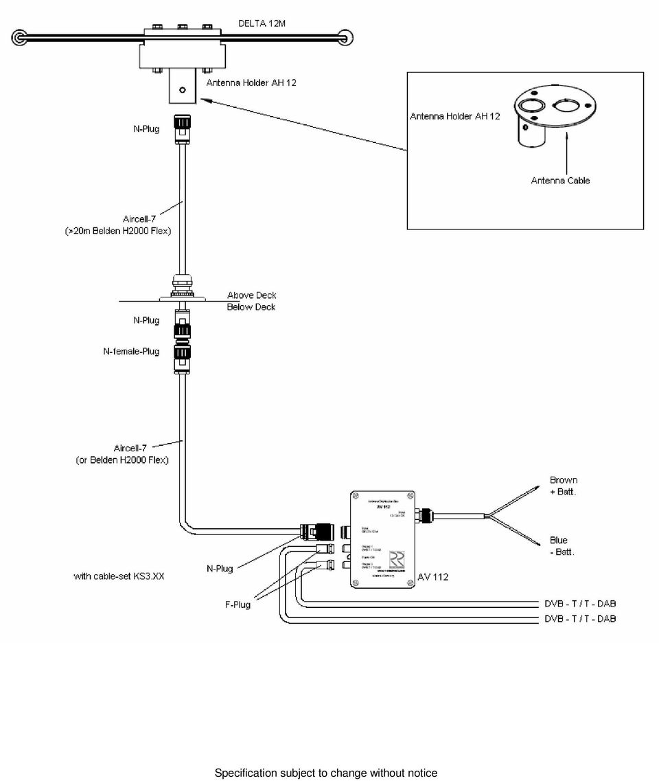
2 Installation der Antennenanlage DELTA 12 M Antennenstandort: Die Antennenanlage DELTA 12 M sollte möglichst im Masttop installiert werden. Oberhalb der Antenne sollten sich keine weiteren Antennen befinden. Antennenkabel: Als Antennenkabel sind für die Antennenanlage DELTA 12 M Koaxialkabel mit 50 Ohm Wellenwiderstand zu verwenden, vorzugsweise Aircell-7 oder Belden H2000 Flex. An der Antennenseite wird ein N-Stecker für die DELTA 12 M verwendet. ACHTUNG! UHF-Stecker (PL- Stecker) sind für diese Antennenanlage NICHT geeignet! Wichtig: Das Kabel muss mit einer Zugentlastung versehen sein! Das Antennenkabel ist auf möglichst kurzem Weg zum Antennenverteiler AV 112 zu führen. Für eine eventuelle Trennstelle am Mastfuß werden N-Stecker (oder auch BNC-Stecker) montiert. Vor dem Anschluss ist das Antennenkabel auf Kurzschluss zu prüfen! Wichtig: Sämtliche Metallteile der Antenne sowie die Steckverbindungen dürfen keine elektrische Verbindung zu anderen Metallteilen des Schiffes haben, da der Kabelaußenleiter mit dem Minuspol des Bordnetzes verbunden ist. Anschluss des Antennenverteilers AV 112: Der Antennenverteiler AV 112 wird unter Deck in der Nähe der anzuschließenden Geräte montiert. Der Anschluss INPUT: DELTA 12 M wird mit der Antenne DELTA 12 M über einen N-Stecker verbunden. Für die Anschlüsse Output1 und Output2: DVB-T / T-DAB werden F-Steckverbinder und 75 Ohm Kabel benötigt. Stromversorgung: Wichtig: Die Stromversorgung darf erst nach Abschluss sämtlicher Installationsarbeiten eingeschaltet werden. Die Stromversorgung sollte über einen Schalter oder Sicherungsautomaten der Schalttafel angeschlossen werden. Wenn keines der angeschlossenen Empfangsgeräte in Betrieb ist, sollte die Stromversorgung für die Antennenanlage ausgeschaltet werden. Die blau isolierte Stromversorgungsleitung wird mit dem Minuspol und die braun isolierte Leitung mit dem Pluspol des 12V- oder 24V-Bordnetzes verbunden. Für eine einwandfreie Funktion der Antennenanlage ist eine fachmännische Installation sämtlicher Verbindungen, insbesondere aller Anschlussstecker unbedingt erforderlich! Schäden durch Nichtbeachtung dieser Hinweise sind von der Garantie ausgeschlossen. Im Zweifelsfalle einen Fachmann zu Rate ziehen!
 sind für diese Antennenanlage NICHT geeignet!")
3 Fehlersuchschema für Antennenanlage DELTA 12 M 1. Überprüfen der Stromversorgung des AV 112 sowie der Sicherung (M 0.2A; 5x20mm). 2. Überprüfen der Steckverbinder und Verbindungen zu TV und Radio. 3. Überprüfen der Stromaufnahme des AV 112: mit angeschlossener Antenne 150 ma ohne angeschlossene Antenne 115 ma 4. Überprüfen des Antennenkabels und der Steckverbindungen. Beim Prüfen des Gleichstromwiderstandes mit einem Ohmmeter wird ein Widerstand von ca. 4,7 kohm gemessen. 5. Überprüfen der Ausgangsspannung vom AV 112 zur Antenne: 12 V Wichtige Hinweise: Starke Schatten im Fernsehbild können durch Reflektionen an Gebäuden, Kränen, etc. entstehen durch die Rundempfangseigenschaft der Antenne DELTA 12 M. Reparaturen an der Antenne oder am Antennenverteiler nur vom autorisierten Fachmann durchführen lassen!

4 Installation of Antenna System DELTA 12 M Antenna position: The antenna system DELTA 12 M should be mounted at the mast-head. No other antennas should be mounted above the antenna system. Antenna cable: For the antenna system DELTA 12 M coaxial cable with a characteristic impedance of 50 Ohm is used, preferably Aircell-7 or Belden H2000 Flex. An N-plug is used at the antenna side of the cable. ATTENTION! UHF-connectors (PL-connectors) may NOT be used for this antenna system! Important: Keep the plug strain-relieved! An optional disconnecting point at the mast-heel is established with N-connectors. Keep the antenna cable to the distribution box AV 112 as short as possible. Check the antenna cable for short circuit before connecting it! Important: All metal parts of the antennas as well as the connectors must not have electrical contact to other metal parts of the ship because the shield of the cable is connected to the negative element of the power supply. Installation of the AV 112: Install the distribution box AV 112 below deck near the instruments connected. Open the AV 112 box to mount it. For that purpose pull off the cover by carefully drawing the corners alternately. Fix the AV 112 box using 2 screws of about 3 mm diameter (see overleaf). Thereafter press the cover to the bottom part until it snaps in. Power supply: Important: Do not switch on the power supply before the installation is completed! Use a switch or cutout of the switch board for the power supply to switch off the AV 112 if no radio or TV is to be received. Connect the power supply connector to the ship s power supply of 12 V or 24 V using a cable of to 1.5 mm² (positive wire next to the fuse; negative wire next to the LED - see overleaf). To guarantee a perfect working antenna it is mandatory to do the installation in a workman-like manner. Any faults caused from neglecting these instructions are excluded from the manufacturers warranty. In case of doubt consult a specialist. Trouble shooting of antenna system DELTA 12 M 1. Check the power supply to the AV 112 (incl. polarity) and the fuse (0.2A medium blow; 5x20 mm). 2. Check the cables and connectors to TV and FM radio. 3. Check the current consumption of the AV 112: 150 ma with antenna DELTA 12 M connected 115 ma with antenna DELTA 12 M not connected 4. Check the antenna cable of the DELTA 12 M, especially the connectors. checking the resistance with an ohmmeter will indicate ca. 4,7 kohm. 5. Check the output voltage from the AV 112 to the antenna: 12 V Important notice: The quality of reception may be influenced by masts, cranes, buildings, etc. due to the omnidirectional characteristics of the antenna. The antenna and distribution box may be repaired by authorized specialists only!

5 Antenna System DELTA 12 M Installation Diagram
6 Specification subject to change without notice
ANTIGUA EINBAUANLEITUNG MOUNTINGINSTRUCTIONS
 ANTIGUA EINBAUANLEITUNG MOUNTINGINSTRUCTIONS Installation der Antennenanlage ANTIGUA Die Antennenanlage ANTIGUA besteht aus den Einzelantennen DELTA 163S und DELTA 12 M, die zu einer Einheit zusammengesetzt
DELTA 1000 S EINBAUANLEITUNG MOUNTINGINSTRUCTIONS
 DELTA 1000 S EINBAUANLEITUNG MOUNTINGINSTRUCTIONS Installation der Antennenanlage DELTA 1000 S Antennenstandort: Die Antennenanlage DELTA 1000 S sollte möglichst im Masttop installiert werden. Oberhalb
ADRIA 3G EINBAUANLEITUNG MOUNTINGINSTRUCTIONS
 ADRIA 3G EINBAUANLEITUNG MOUNTINGINSTRUCTIONS Installation der Antennenanlage ADRIA 3G Die Antennenanlage ADRIA 3G besteht aus den Einzelantennen DELTA 163S und DELTA 3G, die zu einer Einheit zusammengesetzt
ANTIGUA AIS EINBAUANLEITUNG MOUNTINGINSTRUCTIONS
 ANTIGUA AIS EINBAUANLEITUNG MOUNTINGINSTRUCTIONS Installation der Antennenanlage ANTIGUA AIS Die Antennenanlage ANTIGUA AIS besteht aus den Einzelantennen DELTA 163S und DELTA 22 M, die zu einer Einheit
ANTENNENSYSTEM DELTA 12 M EINBAUANLEITUNG ANTENNA SYSTEM DELTA 12 M MOUNTING INSTRUCTIONS
 ANTENNENSYSTEM DELTA 12 M EINBAUANLEITUNG ANTENNA SYSTEM DELTA 12 M MOUNTING INSTRUCTIONS Installation der Antennenanlage DELTA 12 M Antennenstandort: Die Antennenanlage DELTA 12 M sollte möglichst im
Alpha 2T EINBAUANLEITUNG MOUNTINGINSTRUCTIONS
 Alpha 2T EINBAUANLEITUNG MOUNTINGINSTRUCTIONS Installation der Antennenanlage Alpha 2T Die Antennenanlage Alpha 2T besteht aus der Antenne Alpha 2T und dem Antennenverteiler DB1C. Standort der Antenne
ADRIA 4G EINBAUANLEITUNG MOUNTINGINSTRUCTIONS
 ADRIA 4G EINBAUANLEITUNG MOUNTINGINSTRUCTIONS Installation der Antennenanlage ADRIA 4G Die Antennenanlage ADRIA 4G besteht aus den Einzelantennen DELTA 163S und DELTA 4G, die zu einer Einheit zusammengesetzt
IBIZA 3G EINBAUANLEITUNG MOUNTINGINSTRUCTIONS
 IBIZA 3G EINBAUANLEITUNG MOUNTINGINSTRUCTIONS Installation der Antennenanlage IBIZA 3G Die Antennenanlage IBIZA 3G besteht aus den Einzelantennen DELTA 163S, DELTA 3G und DELTA 12 M, die zu einer Einheit
IBIZA 3G AIS EINBAUANLEITUNG MOUNTINGINSTRUCTIONS
 IBIZA 3G AIS EINBAUANLEITUNG MOUNTINGINSTRUCTIONS Installation der Antennenanlage IBIZA 3G AIS Die Antennenanlage IBIZA 3G AIS besteht aus den Einzelantennen DELTA 163S, DELTA 3G und DELTA 22 M, die zu
IBIZA 4G EINBAUANLEITUNG MOUNTINGINSTRUCTIONS
 IBIZA 4G EINBAUANLEITUNG MOUNTINGINSTRUCTIONS Installation der Antennenanlage IBIZA 4G Die Antennenanlage IBIZA 4G besteht aus den Einzelantennen DELTA 163S, DELTA 4G und DELTA 12 M, die zu einer Einheit
IBIZA 3G AIS EINBAUANLEITUNG MOUNTINGINSTRUCTIONS
 IBIZA 3G AIS EINBAUANLEITUNG MOUNTINGINSTRUCTIONS Installation der Antennenanlage IBIZA 3G AIS Die Antennenanlage IBIZA 3G AIS besteht aus den Einzelantennen DELTA 163S, DELTA 3G und DELTA 32 M, die zu
Alpha 2T. Einbauanleitung. Antenna für DVB-T(2), FM, DAB+ Antenna for DVB-T(2), FM, DAB+ Mounting Instructions
, FM, DAB+ Antenna for DVB-T(2), FM, DAB+ Mounting Instructions") Alpha 2T Antenna für DVB-T(2), FM, DAB+ Einbauanleitung Antenna for DVB-T(2), FM, DAB+ Mounting Instructions Installation der Antennenanlage Alpha 2T Die Antennenanlage Alpha 2T besteht aus der Antenne
Alpha 2T Antenna für DVB-T(2), FM, DAB+ Einbauanleitung Antenna for DVB-T(2), FM, DAB+ Mounting Instructions Installation der Antennenanlage Alpha 2T Die Antennenanlage Alpha 2T besteht aus der Antenne
IBIZA 4G AIS EINBAUANLEITUNG MOUNTINGINSTRUCTIONS
 IBIZA 4G AIS EINBAUANLEITUNG MOUNTINGINSTRUCTIONS Installation der Antennenanlage IBIZA 4G AIS Die Antennenanlage IBIZA 4G AIS besteht aus den Einzelantennen DELTA 163S, DELTA 4G und DELTA 32 M, die zu
Alpha 3V. Antenna for VHF Marine Radio, DVB-T(2), FM, DAB+ Antenne für UKW Seefunk, DVB-T(2), FM, DAB+ Einbauanleitung. Mounting Instructions
, FM, DAB+ Antenne für UKW Seefunk, DVB-T(2), FM, DAB+ Einbauanleitung. Mounting Instructions") Alpha 3V Antenne für UKW Seefunk, DVB-T(2), FM, DAB+ Einbauanleitung Antenna for VHF Marine Radio, DVB-T(2), FM, DAB+ Mounting Instructions Installation der Antennenanlage Alpha 3V Die Antennenanlage Alpha
Alpha 3V Antenne für UKW Seefunk, DVB-T(2), FM, DAB+ Einbauanleitung Antenna for VHF Marine Radio, DVB-T(2), FM, DAB+ Mounting Instructions Installation der Antennenanlage Alpha 3V Die Antennenanlage Alpha
DELTA 200 S EINBAUANLEITUNG MOUNTINGINSTRUCTIONS
 DELTA 200 S EINBAUANLEITUNG MOUNTINGINSTRUCTIONS Installation der Antennenanlage DELTA 200 S Antennenstandort: Die Antenne DELTA 200 S sollte möglichst im Masttop installiert werden. Oberhalb der DELTA
Alpha 1C EINBAUANLEITUNG MOUNTINGINSTRUCTIONS
 Alpha 1C EINBAUANLEITUNG MOUNTINGINSTRUCTIONS Installation der Antennenanlage Alpha 1C Die Antennenanlage Alpha 1C besteht aus der Antenne Alpha 1C und dem Antennenverteiler DB1C. Auf die Antenne Alpha
BISCAYA EINBAUANLEITUNG MOUNTINGINSTRUCTIONS
 BISCAYA EINBAUANLEITUNG MOUNTINGINSTRUCTIONS Installation der Antennenanlage BISCAYA Die Antennenanlage BISCAYA besteht aus den Einzelantennen DELTA 200 S und DELTA 12 M, die zu einer Einheit zusammengesetzt
Alpha 3V EINBAUANLEITUNG MOUNTINGINSTRUCTIONS
 Alpha 3V EINBAUANLEITUNG MOUNTINGINSTRUCTIONS Installation der Antennenanlage Alpha 3V Die Antennenanlage Alpha 3V besteht aus der Antenne Alpha 3V und dem Antennenverteiler DB2C. Standort der Antenne
DELTA 200 S EINBAUANLEITUNG MOUNTINGINSTRUCTIONS
 DELTA 200 S EINBAUANLEITUNG MOUNTINGINSTRUCTIONS Installation der Antennenanlage DELTA 200 S Antennenstandort: Die Antenne DELTA 200 S sollte möglichst im Masttop installiert werden. Oberhalb der DELTA
Installation der Antennenanlage PACIFIC 3G
 1 Installation der Antennenanlage PACIFIC 3G Die Antennenanlage PACIFIC 3G besteht aus den Einzelantennen DELTA 200 S, DELTA 3 G und DELTA 12 M, die zu einer Einheit zusammengesetzt montiert werden. Antennenstandort:
BISCAYA AIS EINBAUANLEITUNG MOUNTINGINSTRUCTIONS
 BISCAYA AIS EINBAUANLEITUNG MOUNTINGINSTRUCTIONS Installation der Antennenanlage BISCAYA AIS Die Antennenanlage BISCAYA AIS besteht aus den Einzelantennen DELTA 200 S und DELTA 32 M, die zu einer Einheit
HAWAII 3G EINBAUANLEITUNG MOUNTINGINSTRUCTIONS
 HAWAII 3G EINBAUANLEITUNG MOUNTINGINSTRUCTIONS Installation der Antennenanlage HAWAII 3G Die Antennenanlage HAWAII 3G besteht aus den Einzelantennen DELTA 200 S und DELTA 3G, die zu einer Einheit zusammengesetzt
Installation der Antennenanlage PACIFIC 3G
 1 Installation der Antennenanlage PACIFIC 3G Die Antennenanlage PACIFIC 3G besteht aus den Einzelantennen DELTA 200 S, DELTA 3 G und DELTA 12 M, die zu einer Einheit zusammengesetzt montiert werden. Antennenstandort:
PACIFIC 3G AIS EINBAUANLEITUNG MOUNTINGINSTRUCTIONS
 PACIFIC 3G AIS EINBAUANLEITUNG MOUNTINGINSTRUCTIONS Installation der Antennenanlage PACIFIC 3G AIS Die Antennenanlage PACIFIC 3G AIS besteht aus den Einzelantennen DELTA 200 S, DELTA 3G und DELTA 32 M,
PACIFIC 4G EINBAUANLEITUNG MOUNTINGINSTRUCTIONS
 PACIFIC 4G EINBAUANLEITUNG MOUNTINGINSTRUCTIONS 1 Installation der Antennenanlage PACIFIC 4G Die Antennenanlage PACIFIC 4G besteht aus den Einzelantennen DELTA 200S, DELTA 4G und DELTA 12 M, die zu einer
HAWAII 4G EINBAUANLEITUNG MOUNTINGINSTRUCTIONS
 HAWAII 4G EINBAUANLEITUNG MOUNTINGINSTRUCTIONS Installation der Antennenanlage HAWAII 4G Die Antennenanlage HAWAII 4G besteht aus den Einzelantennen DELTA 200 S und DELTA 4G, die zu einer Einheit zusammengesetzt
ANTENNENSYSTEM PACIFIC EINBAUANLEITUNG ANTENNA SYSTEM PACIFIC MOUNTING INSTRUCTIONS
 ANTENNENSYSTEM PACIFIC EINBAUANLEITUNG ANTENNA SYSTEM PACIFIC MOUNTING INSTRUCTIONS Installation der Antennenanlage PACIFIC Die Antennenanlage PACIFIC besteht aus den Einzelantennen DELTA 200 S, DELTA
Delta 2.4 W-LAN EINBAUANLEITUNG MOUNTINGINSTRUCTIONS
 Delta 2.4 W-LAN EINBAUANLEITUNG MOUNTINGINSTRUCTIONS Installation des Antennensystems DELTA 2.4 W-LAN Installationsvarianten Das DELTA 2.4 W-LAN System kann in verschiedenen Varianten installiert werden:
Delta 2.4 W-Lan EINBAUANLEITUNG MOUNTINGINSTRUCTIONS
 Delta 2.4 W-Lan EINBAUANLEITUNG MOUNTINGINSTRUCTIONS Installation des Antennensystems DELTA 2.4 W-Lan Installationsvarianten Das DELTA 2.4 W-Lan System kann in verschiedenen Varianten installiert werden:
AKTIVE DVB-T ZIMMERANTENNE ANSCHLUSSHINWEISE ACTIVE DVB-T INDOOR ANTENNA CONNECTION INSTRUCTIONS
 K la vi er l ac ko p tik AKTIVE DVB-T ZIMMERANTENNE ANSCHLUSSHINWEISE ACTIVE DVB-T INDOOR ANTENNA CONNECTION INSTRUCTIONS ZA 8970 DRUCKS0682.indd 1 05.09.12 15:15 VerpAckunGsinhAlT UKW / UHF / VHF Flachantenne
Electrical testing of Bosch common rail piezo injectors
 Applies to generation CRI 3: Bosch 10-position order number 0 445 115 = CRI 3-16 (CRI 3.0) 1600 bar 0 445 116 = CRI 3-18 (CRI 3.2) 1800 bar 0 445 117 = CRI 3-20 (CRI 3.3) 2000 bar Tools required: Hybrid
Wandarm inkl. Montagebox und Netzteil Wall bracket incl. installation box and power supply
 Wandarm inkl. Montagebox und Netzteil Wall bracket incl. installation box and power supply Beschreibung und technische Daten: Wandarm (IP-66) mit Montagebox und eingebautem Netzteil Passend für SANTEC
Aufbaudose mit Schalter Spacing box with switch. Montageanleitung mounting instructions
 Aufbaudose mit Schalter Spacing box with switch Montageanleitung mounting instructions body head Aufbaudose mit Schalter Montageanleitung S. 2 mounting instructions p. 9 $ 0.2m Sicherheitshinweise Die
Das mit Robotino ausgelieferte Ladegerät darf nicht mehr verwendet werden.
 NiMH Akkus für Robotino Die NiMH- Akkus ersetzen die mit Robotino ausgelieferten Blei- Gel- Akkus. Das mit Robotino ausgelieferte Ladegerät darf nicht mehr verwendet werden. NiMH accumulators for Robotino
Power supply Interference suppressed acc. to DIN EN /- 4, EN 55011, EN CI. B, power factor corrected Power factor BöSha LED driver
 Operating Instructions LED Mast Double Luminaire Callisto SC DB, incl. Inclination Adjustment, Single-Chip Technology (Please, read carefully before starting operation) Version: 16.01.2017 Model 369-M
Einbauanleitung Komfort CAN Bus Interface 62240
 Einbauanleitung Komfort CAN Bus Interface 62240 Wichtiger Hinweis vor dem Einbau: Bitte beachten Sie generell beim Einbau von elektronischen Baugruppen in Fahrzeugen die Einbaurichtlinien und Garantiebestimmungen
Electrical testing of Bosch common rail Injectors
 Electrical testing of Bosch common rail Injectors Contents: 1. Adapter cable for Hybridtester FSA 050 (article number 0 684 010 050 / 1 687 023 571) 2. Electrical testing of Bosch common rail solenoid
Electrical testing of Bosch common rail solenoid valve (MV) injectors
 injectors") Applies to MV injector, generation: -CRI 1.0 / 2.0 / 2.1 / 2.2 -CRIN 1 / 2 / 3, with K oder AK plug Bosch 10-position order number Bosch-Bestellnummer CRI: 0 445 110 xxx Bosch-Bestellnummer CRIN: 0 445
Applies to MV injector, generation: -CRI 1.0 / 2.0 / 2.1 / 2.2 -CRIN 1 / 2 / 3, with K oder AK plug Bosch 10-position order number Bosch-Bestellnummer CRI: 0 445 110 xxx Bosch-Bestellnummer CRIN: 0 445
NiMH accumulators for Robotino. NiMH Akkus für Robotino. Die NiMH-Akkus ersetzen die mit Robotino ausgelieferten Blei-Gel-Akkus.
 NiMH Akkus für Robotino Die NiMH-Akkus ersetzen die mit Robotino ausgelieferten Blei-Gel-Akkus. Das mit Robotino ausgelieferte Ladegerät darf nicht mehr verwendet werden. NiMH accumulators for Robotino
Anwendungsbeispiele Verstärker Application Examples Amplifiers
 Anwendungsbeispiele Verstärker Application Examples Amplifiers Anwendungsbeispiele Application examples Multimedia-Verteilung in Sternstruktur über Abzweiger Multimedia distribution in star structure
ABB i-bus EIB. EIB Power Supply Units
 ABB i-bus EIB EIB Power Supply Units Product Range Overview EIB Power Supplies ABB STOTZ-KONTAKT GmbH, 2002 - SK 029 F 02 E Product Range Overview EIB Power Supplies! EIB Power Supply, 320 ma SV/S 30.320.5!
Electrical tests on Bosch unit injectors
 Valid for Bosch unit injectors with order numbers 0 414 700 / 0 414 701 / 0 414 702 Parts Kit Magnet*: - F00H.N37.925 - F00H.N37.933 - F00H.N37.934 * For allocation to the 10-place Bosch order number,
Serie B.121. B.121.V Bremse mit Lüfter brake with fan. B.121.R Bremse mit Radiator brake with radiator. B.121 Bremse brake. C.121 Kupplung clutch
 Serie B.11 B.11 D1 Drei Gewindebohrungen zur Befestigung. ACHTUNG: Vor einsetzen der Schraube bitte Gewinde entfernen mit Bohrer ø, threaded holes for fastening ATTENTION: before inserting the screw remove
Installation guide for Cloud and Square
 Installation guide for Cloud and Square 1. Scope of delivery 1.1 Baffle tile package and ceiling construction - 13 pcs. of baffles - Sub construction - 4 pcs. of distance tubes white (for direct mounting)
LED Treiber: Anschlussschemata LED driver: connection diagrams
 Treiber: Anschlussschemata driver: connection diagrams TCI DC MAXI JOLLY DALI für 18W (Konstantstromversorgung), 500mA, dimmbar via Taster (Push) / 1-10V / DALI 6Z1851 Sicherheitshinweise Montagehinweise
i500 Sicherheitsmodul I5MASA000 I5MASA000 safety module Montageanleitung Mounting Instructions
 i500 Sicherheitsmodul I5MASA000 Montageanleitung I5MASA000 safety module Mounting Instructions Allgemeines Erst lesen, dann beginnen 1 1 Allgemeines 1.1 Erst lesen, dann beginnen Lesen Sie vor der Installation
EINBAUHINWEISE INSTALLATION INSTRUCTIONS
 EINBAUHINWEISE INSTALLATION INSTRUCTIONS FÜR JEDEN ANSPRUCH DAS RICHTIGE FAHRWERK. KW automotive GmbH Aspachweg 14 74427 Fichtenberg Telefon: +49 7971 9630-0 Telefax: +49 7971 9630-191 www.kwsuspensions.de
Seitenkoffer Topcases Gepäckträger Lock it System Softbags Aluminiumkoffer Lederkoffer Schutzbügel Hauptständer Chopper-Parts Quad-Parts Accessoires
 Zusatzscheinwerfer Art.-Nr.: 730.665 ab Baujahr 2014 Artikel-Nr.: 730.671 Montage Stück Bestellnr. Bezeichnung 1 700007745 Ion Blue Flooter Scheinwerfer Set: bestehend aus Scheinwerfer Halteschelle ø22-ø39mm
Cable specifications (see page 21) Cable specifications (see page 21)
 Cable specifications (see page 21)") Part No. Y-ConCable-1 4+2 Y-ConCable-2 4+0 for use with Y-Con series plugs, with 4 data and 2 power lines, with Y-Con series plugs, with 4 data lines, mit 4 Daten- und 2 Stromversorgungsleitungen, NICHT
Part No. Y-ConCable-1 4+2 Y-ConCable-2 4+0 for use with Y-Con series plugs, with 4 data and 2 power lines, with Y-Con series plugs, with 4 data lines, mit 4 Daten- und 2 Stromversorgungsleitungen, NICHT
OPERATING INSTRUCTIONS
 OPERATING INSTRUCTIONS for Gas Cartridge Adapter CP250 Part no. 144051 and Gas Cartridge Adapter CV300/470 Part no. 144052 CP 250 CV 300/470 144959_V04 Safety Precautions Possible dangers if the safety
Seitenkoffer Topcases Gepäckträger Lock it System Softbags Aluminiumkoffer Lederkoffer Schutzbügel Hauptständer Chopper-Parts Quad-Parts Accessoires
 Zusatzscheinwerfer Art.-Nr.: 730.105 Montage Seitenkoffer Topcases Gepäckträger Lock it System Aluminiumkoffer Lederkoffer Schutzbügel Hauptständer Chopper-Parts Quad-Parts Accessoires Stück Bestellnr.
A Verstärker-Option / A Amplifier Kit
 A-110-4 Verstärker-Option / A-110-4 Amplifier Kit Deutsch Die erste Version des Moduls A-110-4 hatte einen etwas niedrigen Ausgangspegel (ca. 3-4Vpp). Hiervon betroffen sind nur Standard-Module (silbergraue
DISTRIBUTION: Audio Design GmbH Am Breilingsweg 3 D Kronau / Germany Fon +49(0) Fax +49(0)
 Fax +49(0)") Weitere technische Unterlagen/Informationen sind nicht erhältlich bzw. beschaffbar! DISTRIBUTION: Audio Design GmbH Am Breilingsweg 3 D-76709 Kronau / Germany Fon +49(0)7253-9465-0 Fax +49(0)7253-946510
Weitere technische Unterlagen/Informationen sind nicht erhältlich bzw. beschaffbar! DISTRIBUTION: Audio Design GmbH Am Breilingsweg 3 D-76709 Kronau / Germany Fon +49(0)7253-9465-0 Fax +49(0)7253-946510
web:
 e-mail: info@levolta.com web: www.levolta.com MOBILE POWER PACK DE EN Bedienungsanleitung S. 1 User s manual S. 8 Deutsch Bedienungsanleitung Mobile Power Pack ixmini Bewahren Sie diese Hinweise an einem
Montageanweisung Mounting Instructions
 HD-Splitter für Montagebügel HD-Splitter for back mount frame fixing Montageanweisung Mounting Instructions Einzelkomponenten Individual Components oben / top Gehäuse / housing unten / bottom 4x Frontprofil
SPINNER MOBILE COMMUNICATION
 KOAXIALE ABSCHLUSSWIDERSTÄNDE & DÄMPFUNGSGLIEDER COAXIAL LOADS & ATTENUATORS Abschlusswiderstände übernehmen häufig die Funktion einer Antenne während der Test- oder Einmessphase einer Mobilfunk-Basisstation.
1 Allgemeine Information
 1 Allgemeine Information ACHTUNG! Der Betriebsdruck der Klasse 867 ist 6 bar. Sollte der Druck Ihrer Versorgungsleitung höher als 6 bar sein, muss der Druck an der Versorgungseinheit der Nähmaschine auf
KFT Revision: 00
 Revision: 00 QUICK-LOCK EVO-Träger QUICK-LOCK EVO-Carrier Montagehinweise Fahren Sie nicht ohne Koffer mit montierten Seitenplatten. Wenn sie ohne Gepäck fahren, Seitenplatten demontieren. Alle vom Motorrad
CABLE TESTER. Manual DN-14003
 CABLE TESTER Manual DN-14003 Note: Please read and learn safety instructions before use or maintain the equipment This cable tester can t test any electrified product. 9V reduplicated battery is used in
Hama GmbH & Co KG Postfach Monheim/Germany Tel. +49 (0)9091/502-0 Fax +49 (0)9091/
9091/502-0 Fax +49 (0)9091/") www.hama.de Hama GmbH & Co KG Postfach 80 86651 Monheim/Germany Tel. +49 (0)9091/502-0 Fax +49 (0)9091/502-274 hama@hama.de www.hama.de 00062249-05.05 Multimedia Kit für/for Mercedes Command 2.0 00062249
www.hama.de Hama GmbH & Co KG Postfach 80 86651 Monheim/Germany Tel. +49 (0)9091/502-0 Fax +49 (0)9091/502-274 hama@hama.de www.hama.de 00062249-05.05 Multimedia Kit für/for Mercedes Command 2.0 00062249
Outdoor-Tasche. Operating Instructions Bedienungsanleitung GB D
 00 181243 Outdoor Case Outdoor-Tasche Splish Splash Operating Instructions Bedienungsanleitung GB D A B C D OPEN G Operating instruction 1. Important Notes Children are not permitted to play with the device.
Tilt Wall. Montage- und Gebrauchsanleitung. Assembly instructions and manual.
 Tilt Wall Montage- und Gebrauchsanleitung Assembly instructions and manual www.nyta.eu Montagehinweise & Begriffserklärung Assembly direction and glossary Vor der Montage alle stromführenden Leitungen
The luminaire must be installed and main - tained by a suitably qualified person in compliance with latest installation and safety regulations.
 60 640 98 840 640 Deutsch English 27 Ø42/60 SX 967 /76 SX 966 7 /76 SX 966 Ø42/60 SX 967 7 98 Gewicht / Weight : Kg Max. LPH. : 8000mm Aw. : 0,061m² 0 IP66 WEEE-REG.-NR. DE 2402 Montage und Wartung darf
Installationsanleitung / installation manual - DIMMbox
 Inhalt / Content Funktionsbeschreibung... 2 Anschlusskonfigurationen... 3 Konstantspannung... 3 Konstantstrom... 3 Art der Steuerung... 4 Analogeingang... 4 Digital Addressable Lighting Interface (DALI):...
Funktionsbeschreibung/ Montageanweisung Steuermodul DSM 400 für Dunstabzugshaube DA 6000 W
 Funktionsbeschreibung/ Montageanweisung Steuermodul DSM 400 für Dunstabzugshaube DA 6000 W Operation/Installation Control module DSM 400 for Cooker Hood DA 6000 W de, en M.-Nr. 09 165 660 Inhalt/Contents
18007: 2m Big Wheel Horizontal polarisierte Rundstrahlantenne
 18007: 2m Big Wheel Horizontal polarisierte Rundstrahlantenne Beschreibung Das 'große Rad' ist eine horizontal polarisierte Rundstrahlantenne für das 2m-Band. Üblicherweise werden im 2m-Band scharf bündelnde
Downpipe Ford Focus ST MK3 Kit-Nr.:
 190001081 - Einbauanleitung / Installation Instruction - Downpipe Ford Focus ST MK3 Kit-Nr.: 500001025 Wichtige Hinweise! Diese Montageanleitung ist unbedingt vor Beginn der Einbauarbeiten zu lesen. Die
Ref. Nr BMW 328i (F30)
") Ref. Nr. 11 28 0245 BMW 328i (F30) Montageanleitung BMW 328i Motor: N20B20 HARTGE Leistungssteigerung (Basis 180 kw/245 PS) 213 kw (290 PS) bei 5100 U/min 415 Nm bei 2700 U/min Assembly instructions BMW
Ref. Nr. 11 28 0245 BMW 328i (F30) Montageanleitung BMW 328i Motor: N20B20 HARTGE Leistungssteigerung (Basis 180 kw/245 PS) 213 kw (290 PS) bei 5100 U/min 415 Nm bei 2700 U/min Assembly instructions BMW
BRUUDT Kennzeichenhalter für die Honda NC750X ab 2016 BRUUDT Tail Tidy for the Honda NC750X 2016 and onwards.
 Montageanleitung Mounting instructions BRUUDT Kennzeichenhalter für die Honda NC750X ab 2016 BRUUDT Tail Tidy for the Honda NC750X 2016 and onwards. Noch einmal vielen Dank, dass Sie sich für unsere Produkte
PROFIBUS-DP Repeater 1 to 1 and 1 to 5 with optional level converter module
 LSS PROFIBUS-DP Repeater 1 to 1 and 1 to 5 with optional level converter module The LSS PROFIBUS-DP repeaters 1 to 1 and 1 to 5 are used for coupling up to six PROFIBUS bus segments in RS 485 bus technology.
Cameraserver mini. commissioning. Ihre Vision ist unsere Aufgabe
 Cameraserver mini commissioning Page 1 Cameraserver - commissioning Contents 1. Plug IN... 3 2. Turn ON... 3 3. Network configuration... 4 4. Client-Installation... 6 4.1 Desktop Client... 6 4.2 Silverlight
ITAC Bedienungsanleitung User manual. Originalbedienungsanleitung in deutscher Sprache. Für künftige Verwendung aufbewahren.
 D Bedienungsanleitung User manual Originalbedienungsanleitung in deutscher Sprache. Für künftige Verwendung aufbewahren. This user manual contains important information for installation and operation.
WOR Manu Systems AG Version 1.1
 2016 WOR-0012 Manu Systems AG 09.06.2016 Version 1.1 Online Information... 4 Deutsch... 4 English... 4 Verpackungsinhalt prüfen / Check box content... 5 Teile auspacken / Unpack parts... 6 WOR-0012-0001...
HH-Sicherungseinsätze mit Steckverbindern für Freileitungsmontage HV fuse links with plug-connectors for overheadline fitting
 G- HV fuse links with plug-connectors for overheadline fitting HH1-70 HV fuse links including connectors for overhead line fitting Hochspannungs-Sicherungen mit Anschlussgarnitur bilden einen Set, der
3. Technical data 3. Technische Daten
 661 078 3. Technical data 3. Technische Daten Design / Bauart Pressure switch, vacuum switch and differential pressure switch / Druckwellenschalter, Vakuumschalter und Differenzdruckschalter Function
LED Treiber: Anschlussschemata LED driver: connection diagrams
 ED Treiber: Anschlussschemata ED driver: connection diagrams TCI DC JOY MD für 18W ED (Konstantstromversorgung), 500mA, dimmbar via Phasenabschnittsdimmer / Taster (Push) 6Z 18 50 Sicherheitshinweise Montagehinweise
ASSEMBLY INSTRUCTIONS MONTAGEANLEITUNG. 3 Circuit ( 230V ) Tracks and Adaptors. 3 Phasen ( 230V ) Stromschienen und Adaptoren.
 Tracks and Adaptors. 3 Phasen ( 230V ) Stromschienen und Adaptoren.") Essential safety Informations This product is suitable for 3-circuit track systems ( EUTRAC and comparable). This product is suitable for indoor dry locations only. The track system must be installed and
Essential safety Informations This product is suitable for 3-circuit track systems ( EUTRAC and comparable). This product is suitable for indoor dry locations only. The track system must be installed and
LAN-Mini/R-485 Handbuch Manual
 LAN-Mini/R-485 Handbuch Manual - Konverter - steckbare Schraubklemme - LAN-Kabel - CD - Hutschienenclip Lieferumfang Shipment - converter - pluggable locking ring - LAN-cord - CD - DIN rail clip Optionales
asled3000 Dimmbarer High Power LED-Treiber
 asled3000 Dimmbarer High Power LED-Treiber A1.20 01/07 Leistungsmerkmale asled3000 ist ein dimmbares Treibermodul zur Versorgung von Hochleistungs-LEDs beliebiger Lichtfarbe. Es kann bis zu 6 LEDs mit
Building Instructions. Aufbauanleitung. Service-Hotline:
 86488-2006 02.02.2012 Aufbauanleitung Building Instructions Service-Hotline:+49 421 38693 33 86488-2006 Vergleichen Sie zuerst die Materialliste mit Ihrem Paketinhalt! Bitte haben Sie Verständnis, daß
Datasheet. Page 1 of 7
 Features 20 Encoder Positions 4-way Joystick LED-Illumination high quality signal processing Benefits Tactile multi purpose application premium design Hall Effect technology Applications Multiple switch
CB-Radio AE 5090 XL Modification
 CB-Radio AE 5090 XL Modification Downloaded from www.cbradio.nl AE5290XL MULTI Power and channel settings Power settings by Plug-In Jumper Factory Power setting is automatic 1-4 Watt switching with country
EINBAUHINWEISE INSTALLATION INSTRUCTIONS
 EINBAUHINWEISE INSTALLATION INSTRUCTIONS FÜR JEDEN ANSPRUCH DAS RICHTIGE FAHRWERK. KW automotive GmbH Aspachweg 14 74427 Fichtenberg Telefon: +49 7971 9630-0 Telefax: +49 7971 9630-191 www.kwsuspensions.de
2. For Entity concept use the appropriate parameters from above to ensure the following: V t or V OC V max
 Class I, II, III, Div. 1, Group A - G or Class I, Zone 0, Group IIC/IIB Hazardous Locations Nonhazardous or Class I, Div. 2, Group A, B, C, D or Class I, Zone 2, Group IIC Hazardous Locations The copying,
mobilcom-debitel SmartHome Schnell-Start-Anleitung Quick Start Guide
 mobilcom-debitel SmartHome Schnell-Start-Anleitung Quick Start Guide 1. Cube anschließen 1. Connect Cube n Schließen Sie den Cube an die Stromversorgung an. n Legen Sie die Batterien polungsrichtig in
PoE Kit Mounting Instructions SG/XG 210/230/310/330/430/450
 PoE Kit Mounting Instructions PoE Kit Mounting Instructions Please note ÌÌ Before installing/removing any LAN module please make sure that the appliance is powered off and power cables are removed. ÌÌ
USB -> Seriell Adapterkabel Benutzerhandbuch
 USB -> Seriell Adapterkabel Benutzerhandbuch 1. Produkt Eigenschaften 1 2. System Vorraussetzungen 1 3. Treiber Installation (Alle Windows Systeme) 1 4. Den COM Port ändern 2 5. Einstellen eines RS232
Standard Power Integrated Module
 Standard Power Integrated Module flowpim 0 Features/ Eigenschaften - 1/3 Phases Input Rectifier - brake chopper - 3 phases inverter IGBT + FRED with open emitter - NTC module types / Produkttypen part
Typenreihe GH Lifting Solenoids
 Hubmagnete Lifting Solenoids Bauart Hubmagnete der Reihe GH können mit Durchmessern zwischen 5 mm und 65 mm und mit Hublängen von 8 bis 60 mm gefertigt werden. Serien mäßig wer den sie mit Wellenenden
BNC - Programm BNC Programme
 - Programm S. 215 Adapter Adapters S. 217 -Adapterleitungen adapter leads S. 218 Sicherheits-Adapter Safety adapters www.schuetzinger.de 213 - Programm Die HF-Steckverbindung der Serie ist die häufigste
Ladeluftkühler / Intercooler Mercedes Benz (CL)A 250 Kit-Nr.:
A 250 Kit-Nr.:") 190001042 - Einbauanleitung / Installation Instruction - Ladeluftkühler / Intercooler Mercedes Benz (CL)A 250 Kit-Nr.: 200001058 Wichtige Hinweise! Diese Montageanleitung ist unbedingt vor Beginn der Einbauarbeiten
190001042 - Einbauanleitung / Installation Instruction - Ladeluftkühler / Intercooler Mercedes Benz (CL)A 250 Kit-Nr.: 200001058 Wichtige Hinweise! Diese Montageanleitung ist unbedingt vor Beginn der Einbauarbeiten
Art : 23P BPI 001 => 16,-
 Universal Brake Pad Wear Indicator for single or double cable systems. kit can be retrofitted at any time to V-Maxx Autosport Big Brake Kit Universal Bremsbelag-Verschleißanzeige für 1 oder 2 Kabel Systeme.
VIDEO CALL CAMERA G-VCAM-01
 VIDEO CALL CAMERA G-VCAM-01 EN AUS GUTEM GRUND ENGLISH 07-10 2 SAFETY AND INFORMATION Safety 7 This camera is designed to transmit video and audio signals. All other uses are expressly prohibited. 7 Protect
LED Treiber: Anschlussschemata LED driver: connection diagrams
 ED Treiber: Anschlussschemata ED driver: connection diagrams TCI DC JOY MD für 18W ED (Konstantstromversorgung), 500mA, dimmbar via Phasenabschnittsdimmer / Taster (Push) 6Z 18 50 Sicherheitshinweise Montagehinweise
OPERATING INSTRUCTIONS Test pump ZG 5.1. and ZG 5.2.
 Elektromotoren und Gerätebau Barleben GmbH OPERATING INSTRUCTIONS Test pump ZG 5.1. and ZG 5.2. Elektromotoren und Gerätebau Barleben GmbH 2 Inhaltsverzeichnis Page 1 Use 4 2 Design features 4 2.1 Test
Optischer Rückumsetzer Zirkular Optical Converter Circular OPM-CDL. Bedienungsanleitung/ Operating manual
 Optischer Rückumsetzer Zirkular Optical Converter Circular OPM-CDL Bedienungsanleitung/ Operating manual 0901866 1 Montage- und Sicherheitshinweise 2 Beschreibung Der optische Rückumsetzer OPM-CDL von