VS tW. USER MANUAL BEDIENUNGSANLEITUNG
|
|
|
- Benedict Baumhauer
- vor 5 Jahren
- Abrufe
Transkript


1 VS tW USER MANUAL BEDIENUNGSANLEITUNG

2 USER MANUAL VS tW Safety Instructions Devices must be installed by qualified personnel in compliance with all pertaining regulations. Always refer to the technical parameters in the data sheet. All items are subject to technical modification. Refer to the attached User Manual as a basis for correct use. Protect device against moisture. Ensure the correct internal wiring according to installation manual! Note! Before attempting any work, make sure device is separated from main power. Make sure protection against line voltage shock is provided during installation. Note that adjacent parts or devices must be temperature proof up to 90 C. Do not operate electronic devices with inductive consumers (fluorescent lamps, gas discharge lamps, ventilators etc.) in the same electric circuit. Activation of inductive consumers can cause damage to the operating device. Do not place heat insulation material on the device. Mind the operating temperatures of the device according to the technical data sheet. Before drilling the mounting holes or cutting the lamp cutout, take precautions not to harm or damage any power lines underneath. Note and mind voltage label on the device. Do not cross primary and secondary lines. Do not interconnect secondary lines of power supply blocks. The device must only be powered up with lamp connected! Connecting the lamp to the powered-up device can cause damage to the lamp! (voids product warranty!) 2
3 Scope of delivery Check completeness of supplied device immediately after receipt. In delivery included: User Manual VS 600 If you detect any transportation damage or differencies between specified packing contents and your unpacked delivery, please contact your dealer immediately. 3
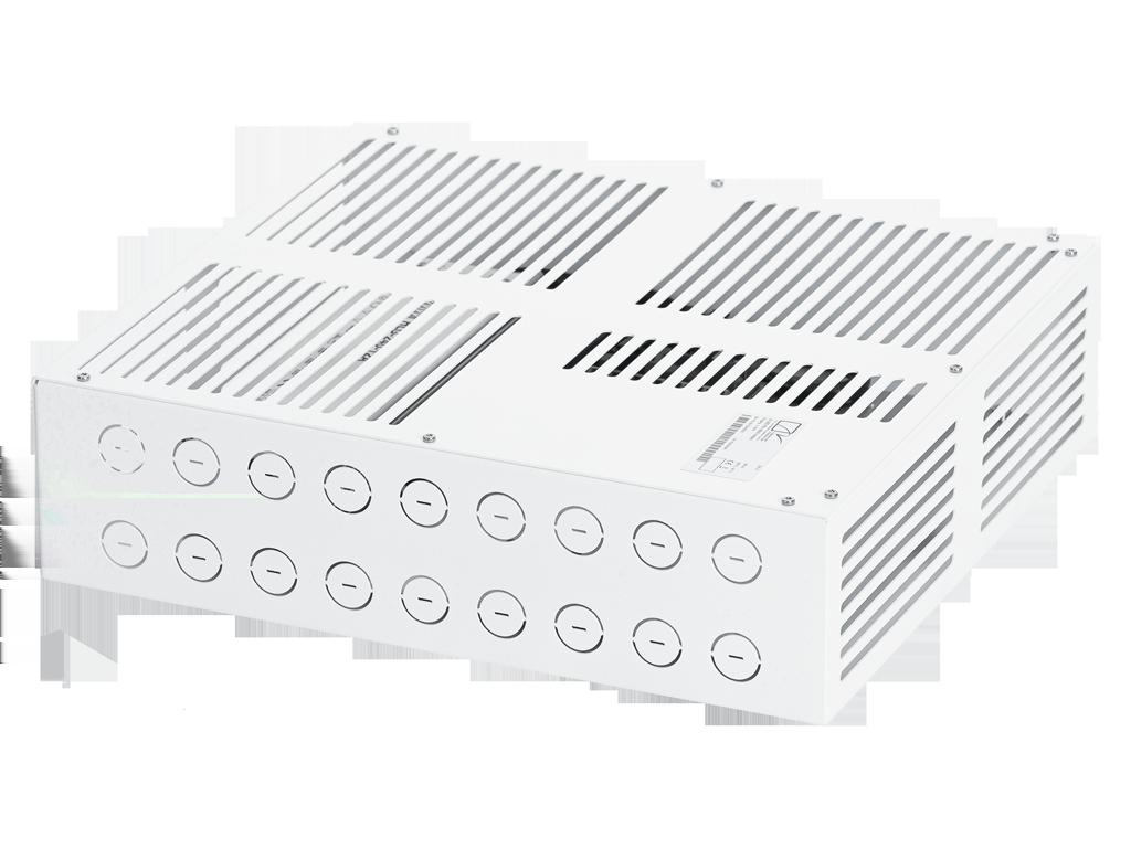
4 Technical Data Dimensions 350 mm x 320 mm x 90 mm [B x T x H] in x in x 3.55 in [B x T x H] Control 0-10 V, DALI, DMX, POT Input Voltage Power supply: internal , 277 VAC (50-60 Hz) VDC Power Consumption Max. 660 W Power Factor Correction > 0,94 Protection Class I Output Voltage 36 VDC Inrush COLD START 70A(t=1000 s measured at 50% I) at 230VAC; width peak Per NEMA 410 Operating Temperature Range -20 C / +40 C -4 F / +104 F Housing Steel-sheet, powdercoated Housing Color(s) White (RAL 9010) Weight 8,1 kg (17.86 lbs) Ingress Protection IP20 Environment indoor Warranty Certification Months
5 Engineering Drawing 5
6 Wiring Input rail mounted terminal block, 0.25 mm² - 4 mm² (22 AWG - 12 AWG) Output rail mounted terminal block, mm² (22 AWG - 12 AWG) 6
7 Mounting 1. Remove the device from the shipping box and check for completeness and possible damage. 2. Loosen the screws on the housing and remove the cover 3. Break the selected parts of the perforation. In accordance with the required cables to break the selected parts of the perforation to use your cable connection. Case perforation d = 22 mm [0.86 in]. Attention: Device must only be mounted in the positions (see picture) as indicated. 7
8 4. Mounting: Drill four mounting holes into mounting surface as indicated. Mind the drill markings in the drawing and check mounting surface for firmness and back venting of device. All measures given in millimeters. 5. Finish your work: Connect fixture line, data line and power line according to installation instructions (point 6). Check your connections and close the cover using the 14 screws provided (max. torque 8 Nm). Device must be used with closed cover only. 8
9 Commissioning 1. Wiring tantulus hp2 tunablewhite 9
10 2. Setup 1. Mode of operation DMX DALI 2. Set Led groups 1-4L CCWW für tantulus tunablewhite 10
11 Operation 1. DALI 1. Mode of operation DALI 2. Set Led groups e.g. for tantulus tunable White 1-4L CCWW 11
12 2. DMX-addressing For addressing the power supply the addressing device scriptus m can be used. Default value is DMX-Address
13 v Diming Calibration to Source: 1. Press calibration button to start 2. Set minimum Level to the signal input of the power supply 3. Press calibration button to teach in the Level. 4. Set maximum Level to the signal input of the power supply. 5. Press calibration button to teach in the Level and finish the calibration. The power supply is calibrated to the signal level of your source now. Attention! Minimumlevel on the analog input -> 100% intensity Maximumlevel on the anlaog input -> 0% intensity 13
14 4. System Overview Power Supply Leader Cable tantulus 3 optional: Connection Cable or further tantulus 3 with end to end connection 5. Fuses Used fuses: North America: 2,8 A, slow, ¼ x 1¼ Europe: 5A, slow, ¼ x 1¼ 14
15 Maintenance Clean device from dirt and residue regularly. Use solvent-free cleaning agents only and do not employ aggressive chemicals or high pressure cleaner. Operate device only after complete drying. Use in low-dust areas Keep ventilation slots clean, check frequently Conformity Manufacturer Bion Technologies GmbH Lindberghstrasse Koenigsbrunn Tel: +49 (0)8231/ Fax: +49 (0)8231/ YouTube: All rights reserved / Subject to change / Specifications may change without notice 15
16 BEDIENUNGSANLEITUNG VS tW Sicherheitshinweise Anschluss und Bedienung dieses Geräts sollte ausschließlich von qualifiziertem Fachpersonal in Übereinstimmung mit allen geltenden Vorschriften erfolgen. Beachten Sie immer die technischen Daten auf dem Datenblatt. Technische Änderungen vorbehalten. Die beigefügte Gebrauchsanleitung ist Voraussetzung für den ordnungsgemäßen Gebrauch. Gerät vor Nässe schützen. Die Aderbelegung im inneren des Gerätes ist gemäß Installationsanweisung zu beachten! Achtung! Vor Beginn der Arbeiten Gerät vom Netz trennen. Der Schutz gegen elektrischen Schlag ist beim Einbau sicherzustellen. Beim Einbau ist darauf zu achten dass benachbarte Bauteile einer Temperatur von 90 C standhalten. Elektronische Betriebsgeräte nicht gemeinsam mit induktiven Lasten (Leuchtstofflampen, Entladungslampen, Ventilatoren usw.) im gleichen Stromkreis betreiben. Beim Schalten induktiver Lasten können Defekte am Betriebsgerät entstehen. Wärmedämmung darf nicht auf dem Betriebsgerät liegen. Beim Einbau ist auf die, in den technischen Daten angegebenen, Betriebstemperaturen zu achten. Vor dem Bohren oder Ausschneiden der Befestigungslöcher bzw. des Geräteausschnittes ist darauf zu achten, das eventuell darunter liegenden Netzleitungen nicht beschädigt werden. Spannungskennzeichnung auf dem Betriebsgerät beachten. Ein einwandfreier elektrischer Übergang ist beim Anschließen der Leuchte an das Betriebsgerät zu gewährleisten. Primär- und Sekundärleitungen müssen kreuzungsfrei verlegt werden. Sekundärleitungen mehrerer Betriebsgeräte dürfen nicht miteinander verbunden werden. Das Betriebsgerät darf nur mit angeschlossener Leuchte unter Spannung gesetzt werden! Wenn die Leuchte unter Spannung mit dem Netzteil verbunden wird kann die Leuchte beschädigt werden! (Kein Gewährleistungsfall) 16
17 Lieferumfang Packen Sie alle Teile aus. Prüfen Sie den Verpackungsinhalt auf sichtbare Transportschäden. Prüfen Sie, ob der Verpackungsinhalt vollständig ist. Im Lieferumfang enthalten: Bedienungsanleitung VS 600 Wenn Sie Transportschäden oder Unstimmigkeiten zwischen dem hier angegebenen Lieferumfang und Verpackungsinhalt feststellen, informieren Sie unverzüglich Ihre Verkaufstelle. 17
18 Technische Daten Abmessungen 350 mm x 320 mm x 90 mm [B x T x H] in x in x 3.55 in [B x T x H] Steuerung 0-10 V, DALI, DMX, POT Eingangsspannung Netzteil: intern , 277 VAC (50-60 Hz) VDC Wirkleistungsaufnahme Max. 660 W Blindleistungskompensation > 0,94 Schutzklasse I Ausgangsspannung 36 VDC Einschaltstrom Kaltstart 70A(t=1000 s gemessen an 50% 230VAC; mit Peak nach NEMA 410 Betriebstemperaturbreich -20 C / +40 C -4 F / +104 F Gehäuse Stahlblech, pulverbeschichtet Gehäusefarbe(n) Weiß (RAL 9010) Gewicht 8,1 kg (17.86 lbs) Schutzart IP20 Umgebung indoor Gewährleistung Zulassungen Monate
19 Technische Zeichnung 19
20 Verkabelung Anschluss Klemmblock, 0,25 mm² - 4 mm² (22 AWG - 12 AWG) Ausgang Reihenklemmen, 0,25-4 mm² (22 AWG - 12 AWG) 20


 3.")


21 Montage 1. Entnehmen Sie das Gerät der Verpackung und prüfen Sie Ihre Lieferung auf Vollständigkeit und Beschädigungen. 2. Lösen Sie die Schrauben auf dem Deckel des Gerätes und entfernen Sie die Abdeckung. Deckelverschraubung: 14 Schrauben (2,9 x 6,5 T10) 3. Herausbrechen der Kabelöffnung: Brechen Sie entsprechend den benötigten Leitungen die markierten Teile aus der Perforation heraus um Ihre Kabelverschraubung einzusetzen. Gehäusedurchbruch d = 22 mm [0,86 in]. ACHTUNG: Gerät darf ausschließlich in diesen Positionen (siehe Skizze) montiert werden 21
22 4. Befestigung: Bohren Sie, wie vorgegeben, am vorgesehenen Montageplatz vier Befestigungslöcher. Beachten Sie hierzu die Bohrmarkierungen in der Skizze und achten Sie auf entsprechende Untergrundfestigkeit sowie Hintergrundbelüftung des Gerätes. Alle Maße sind in Millimeter angegeben. 5. Abschlussarbeiten: Schließen Sie die Leuchtenleitung, Datenleitung und die Netzleitung gemäß Inbetriebnahmeanweisung (Punkt 5 - Bedienung) an. Prüfen Sie Ihre Anschlüsse und verschließen Sie den Deckel mit den mitgelieferten 14 Schrauben (max. Drehmoment 8 Nm). Gerät darf ausschließlich mit verschlossenem Deckel betrieben werden. 22

23 Inbetriebnahme 1. Anschluss tantulus hp2 tunablewhite 23
24 2. Setup 1. Betriebsart auswählen DMX DALI 2. Leuchtengruppierung 1-4L CCWW für tantulus tunablewhite 24
25 Installation and commissioning 1. DALI 1. Betriebsart auswählen DALI 2. Leuchtengruppierung z.b.: für tunable White 1-4L CCWW 25

26 2. DMX-Addressierung Die Adressierung des Netzteils kann durch das Adressiergerät scriptus m vorgenommen werden. Standardeinstellung ist DMX-Adresse

27 v Dimmung Kalibrierung der Signalpegel: 1. Drücken Sie den Kalibrierungsknopf 1x um den Abgleich zu starten. 2. Legen Sie die Minimalspannung am Signaleingang des Netzteils an. 3. Bestätigen Sie den Signalpegel durch 1x drücken des Kalibrierknopfs. 4. Legen Sie die Maximalspannung am Signaleingang des Netzteils an. 5. Bestätigen Sie den Signalpegel wieder durch 1x drücken des Kalibrierknopfs. Das Netzteil ist nun auf Ihre Anlagenpegel konfiguriert und ist analog steuerbar. Achtung! Minimalspannung Eingang -> 100% Intensität Maximalspannung Eingang -> 0% Intensität 27
28 4. Systemaufbau Netzteil Anschlusskabel tantulus 3 optional: Verbindungskabel oder weitere tantulus 3 end to end 5. Sicherungen Verwendete Feinsicherungen: Nord Amerika: 2,8 A, träge, ¼ x 1¼ Europa: 5A, träge, ¼ x 1¼ 28
29 Wartung + Pflege Gerät regelmäßig mit einem feuchten Tuch reinigen. Verwenden Sie ausschließlich lösungsmittelfreie Reinigungsmittel und verwenden Sie keine Chemikalien. Achten Sie auf eine staubarme Umgebung Lüftungsöffnungen regelmäßig kontrollieren und säubern Konformität Hersteller Bion Technologies GmbH Lindberghstrasse Koenigsbrunn Tel: +49 (0)8231/ Fax: +49 (0)8231/ info@biontechnologies.com YouTube: All rights reserved / Subject to change / Specifications may change without notice 29
30 Powered by TCPDF ( Lindberghstrasse Koenigsbrunn Tel: +49 (0)8231/ Fax: +49 (0)8231/ YouTube: , BION TECHNOLOGIS GMBH All rights reserved / Subject to change / Specifications may change without notice
Power Supply ND Series. USER MANUAL BEDIENUNGSANLEITUNG
 Power Supply ND Series USER MANUAL BEDIENUNGSANLEITUNG www.biontechnologies.com USER MANUAL Power Supply ND Series Safety Instructions Devices must be installed by qualified personnel in compliance with
linea m mounting SET USER MANUAL BEDIENUNGSANLEITUNG
 linea m mounting 90-228 SET plate USER MANUAL BEDIENUNGSANLEITUNG www.biontechnologies.com USER MANUAL linea m mounting 90-228 SET plate Safety Instructions Devices must be installed by qualified personnel
PS XLR CON. USER MANUAL BEDIENUNGSANLEITUNG
 PS 180-12 XLR CON USER MANUAL BEDIENUNGSANLEITUNG www.biontechnologies.com USER MANUAL PS 180-12 XLR CON Safety Instructions Devices must be installed by qualified personnel in compliance with all pertaining
PS XLR CON. USER MANUAL BEDIENUNGSANLEITUNG
 PS 360-12 XLR CON USER MANUAL BEDIENUNGSANLEITUNG www.biontechnologies.com USER MANUAL PS 360-12 XLR CON Safety Instructions Devices must be installed by qualified personnel in compliance with all pertaining
linea s RGB RGBW USER MANUAL BEDIENUNGSANLEITUNG
 linea s RGB RGBW USER MANUAL BEDIENUNGSANLEITUNG www.biontechnologies.com USER MANUAL linea s RGB RGBW Safety Instructions Devices must be installed by qualified personnel in compliance with all pertaining
tectum m RGB RGB USER MANUAL BEDIENUNGSANLEITUNG
 tectum m RGB RGB USER MANUAL BEDIENUNGSANLEITUNG www.biontechnologies.com USER MANUAL tectum m RGB RGB Safety Instructions Devices must be installed by qualified personnel in compliance with all pertaining
Series. USER MANUAL BEDIENUNGSANLEITUNG
 LED-Power Series Supply ED USER MANUAL BEDIENUNGSANLEITUNG www.biontechnologies.com USER MANUAL LED-Power Series Supply ED Safety Instructions Devices must be installed by qualified personnel in compliance
linea s purewhite purecolor USER MANUAL BEDIENUNGSANLEITUNG
 linea s purewhite purecolor USER MANUAL BEDIENUNGSANLEITUNG www.biontechnologies.com USER MANUAL linea s purewhite purecolor Safety Instructions Devices must be installed by qualified personnel in compliance
funis m surface purewhite
 funis m surface purewhite USER MANUAL BEDIENUNGSANLEITUNG www.biontechnologies.com USER MANUAL funis m surface purewhite Safety Instructions Devices must be installed by qualified personnel in compliance
tectum m purewhite purecolor USER MANUAL BEDIENUNGSANLEITUNG
 tectum m purewhite purecolor USER MANUAL BEDIENUNGSANLEITUNG www.biontechnologies.com USER MANUAL tectum m purewhite purecolor Safety Instructions Devices must be installed by qualified personnel in compliance
funis m square 2000 purewhite
 funis m square 2000 purewhite USER MANUAL BEDIENUNGSANLEITUNG www.biontechnologies.com USER MANUAL funis m square 2000 purewhite Safety Instructions Devices must be installed by qualified personnel in
X-LED Line 7.5 RGB. USER MANUAL BEDIENUNGSANLEITUNG
 X-LED Line 7.5 RGB USER MANUAL BEDIENUNGSANLEITUNG www.biontechnologies.com USER MANUAL X-LED Line 7.5 RGB Safety Instructions Devices must be installed by qualified personnel in compliance with all pertaining
X-LED Mesh 7.5 RGB. USER MANUAL BEDIENUNGSANLEITUNG
 X-LED Mesh 7.5 RGB USER MANUAL BEDIENUNGSANLEITUNG www.biontechnologies.com USER MANUAL X-LED Mesh 7.5 RGB Safety Instructions Devices must be installed by qualified personnel in compliance with all pertaining
funis m square purewhite
 funis m square purewhite USER MANUAL BEDIENUNGSANLEITUNG www.biontechnologies.com USER MANUAL funis m square purewhite Safety Instructions Devices must be installed by qualified personnel in compliance
linea m hpc outdoor RGB RGBW
 linea m hpc outdoor RGB RGBW USER MANUAL BEDIENUNGSANLEITUNG www.biontechnologies.com USER MANUAL linea m hpc outdoor RGB RGBW Safety Instructions Devices must be installed by qualified personnel in compliance
linea m hp outdoor purewhite purecolor
 linea m hp outdoor purewhite purecolor USER MANUAL BEDIENUNGSANLEITUNG www.biontechnologies.com USER MANUAL linea m hp outdoor purewhite purecolor Safety Instructions Devices must be installed by qualified
funis m round 2000 purewhite
 funis m round 2000 purewhite USER MANUAL BEDIENUNGSANLEITUNG www.biontechnologies.com USER MANUAL funis m round 2000 purewhite Safety Instructions Devices must be installed by qualified personnel in compliance
coma l tunablewhite USER MANUAL BEDIENUNGSANLEITUNG
 coma l tunablewhite USER MANUAL BEDIENUNGSANLEITUNG www.biontechnologies.com USER MANUAL coma l tunablewhite Safety Instructions Devices must be installed by qualified personnel in compliance with all
scriptus m USER MANUAL BEDIENUNGSANLEITUNG
 scriptus m USER MANUAL BEDIENUNGSANLEITUNG www.biontechnologies.com USER MANUAL scriptus m Safety Instructions Devices must be installed by qualified personnel in compliance with all pertaining regulations.
tantulus xhp indoor tunablewhite
 tantulus xhp indoor tunablewhite USER MANUAL BEDIENUNGSANLEITUNG www.biontechnologies.com USER MANUAL tantulus xhp indoor tunablewhite Safety Instructions Devices must be installed by qualified personnel
tantulus eco indoor purewhite purecolor
 tantulus eco indoor purewhite purecolor USER MANUAL BEDIENUNGSANLEITUNG www.biontechnologies.com USER MANUAL tantulus eco indoor purewhite purecolor Safety Instructions Devices must be installed by qualified
tantulus 3 eco indoor purewhite purecolor
 tantulus 3 eco indoor purewhite purecolor USER MANUAL BEDIENUNGSANLEITUNG www.biontechnologies.com USER MANUAL tantulus 3 eco indoor purewhite purecolor Safety Instructions Devices must be installed by
The luminaire must be installed and main - tained by a suitably qualified person in compliance with latest installation and safety regulations.
 60 640 98 840 640 Deutsch English 27 Ø42/60 SX 967 /76 SX 966 7 /76 SX 966 Ø42/60 SX 967 7 98 Gewicht / Weight : Kg Max. LPH. : 8000mm Aw. : 0,061m² 0 IP66 WEEE-REG.-NR. DE 2402 Montage und Wartung darf
Aufbaudose mit Schalter Spacing box with switch. Montageanleitung mounting instructions
 Aufbaudose mit Schalter Spacing box with switch Montageanleitung mounting instructions body head Aufbaudose mit Schalter Montageanleitung S. 2 mounting instructions p. 9 $ 0.2m Sicherheitshinweise Die
DATENBLATT / DATASHEET
 DATENBLATT / DATASHEET AEQUILUX DMX PLAYER 1024 / 2048 Abb. Ähnlich Illustration similar BESCHREIBUNG / DESCRIPTION Der AEQUILUX DMX Player dient zur Lichtsteuerung des AEQUILUX Systems. Das Gerät kann
Wandarm inkl. Montagebox und Netzteil Wall bracket incl. installation box and power supply
 Wandarm inkl. Montagebox und Netzteil Wall bracket incl. installation box and power supply Beschreibung und technische Daten: Wandarm (IP-66) mit Montagebox und eingebautem Netzteil Passend für SANTEC
tantulus hp outdoor purewhite
 tantulus hp outdoor purewhite USER MANUAL BEDIENUNGSANLEITUNG www.biontechnologies.com USER MANUAL tantulus hp outdoor purewhite Safety Instructions Devices must be installed by qualified personnel in
Electrical tests on Bosch unit injectors
 Valid for Bosch unit injectors with order numbers 0 414 700 / 0 414 701 / 0 414 702 Parts Kit Magnet*: - F00H.N37.925 - F00H.N37.933 - F00H.N37.934 * For allocation to the 10-place Bosch order number,
Qualitätsmanagement-Handbuch Serviceinformation: _Serviceinformation H0201_1_Batterietrennschalter.doc Formblatt. ÜS;Linearlifte AL1
 Serviceinformation Thema Batterietrennschalter 200185065 kann brechen Seite:1/7 Produktgruppe ÜS;Linearlifte AL1 Artikelnummer Produktgruppencode H0201 Servicecode 200185065 H0201 K0012 A0001 Verfasser
LED Treiber: Anschlussschemata LED driver: connection diagrams
 Treiber: Anschlussschemata driver: connection diagrams TCI DC MAXI JOLLY DALI für 18W (Konstantstromversorgung), 500mA, dimmbar via Taster (Push) / 1-10V / DALI 6Z1851 Sicherheitshinweise Montagehinweise
HEAG 151, 152, 153, 154 Digital Converter
 Montage- und Betriebsanleitung Installation and operating instructions MB095-11055704 Baumer_HEAG151-152-153-154_II_DE-EN (16A1) HEAG 151, 152, 153, 154 Digital Converter 1-2 Allgemeine Hinweise - Funktionsweise
Outdoor-Tasche. Operating Instructions Bedienungsanleitung GB D
 00 181243 Outdoor Case Outdoor-Tasche Splish Splash Operating Instructions Bedienungsanleitung GB D A B C D OPEN G Operating instruction 1. Important Notes Children are not permitted to play with the device.
WE-EF LEUCHTEN. Montage- und Wartungshinweise für Linear-Wandleuchten Serie VLR100 LED
 WE-EF LEUCHTEN Montage- und Wartungshinweise für Linear-Wandleuchten Serie VLR100 LED Installation and Maintenance Instructions for Linear Wallwasher VLR100 LED Series Linear Wandleuchten Linear Wallwasher
Produktdatenblatt. Artikel Nr.: Wandaufbauleuchte, Rosado, Weiß, V AC/50-60Hz, 1x max. 40,00 W + 60,00 W.
 Produktdatenblatt Artikel Nr.: 341005 Wandaufbauleuchte, Rosado, Weiß, 220-240V AC/50-60Hz, 1x max. 40,00 W + 60,00 W Technische Daten Charakteristik Material Farbe Glas Weiß Optik im Lieferumfang Elektrische
Produktdatenblatt. Artikel Nr.: Wandaufbauleuchte, Arianna, Weiß, V AC/50-60Hz, 1x max. 80,00 W. Technische Daten.
 Produktdatenblatt Artikel Nr.: 341035 Wandaufbauleuchte, Arianna, Weiß, 220-240V AC/50-60Hz, 1x max. 80,00 W Technische Daten Charakteristik Material Farbe Optik Gips Weiß überstreichbar im Lieferumfang
Produktdatenblatt. Artikel Nr.: Wandaufbauleuchte, Aviar, Weiß-satiniert, V AC/50-60Hz, 40,00 W. Technische Daten.
 Produktdatenblatt Artikel Nr.: 341114 Wandaufbauleuchte, Aviar, Weiß-satiniert, 220-240V AC/50-60Hz, 40,00 W Technische Daten Charakteristik Material Farbe Glas Weiß-satiniert Optik im Lieferumfang Elektrische
Power supply Interference suppressed acc. to DIN EN /- 4, EN 55011, EN CI. B, power factor corrected Power factor BöSha LED driver
 Operating Instructions LED Mast Double Luminaire Callisto SC DB, incl. Inclination Adjustment, Single-Chip Technology (Please, read carefully before starting operation) Version: 16.01.2017 Model 369-M
Electrical testing of Bosch common rail piezo injectors
 Applies to generation CRI 3: Bosch 10-position order number 0 445 115 = CRI 3-16 (CRI 3.0) 1600 bar 0 445 116 = CRI 3-18 (CRI 3.2) 1800 bar 0 445 117 = CRI 3-20 (CRI 3.3) 2000 bar Tools required: Hybrid
Produktdatenblatt. Artikel Nr.: Wandaufbauleuchte, Giorgia, Weiß, V AC/50-60Hz, 25,00 W. Technische Daten.
 Produktdatenblatt Artikel Nr.: 341033 Wandaufbauleuchte, Giorgia, Weiß, 220-240V AC/50-60Hz, 25,00 W Technische Daten Charakteristik Material Farbe Optik Gips Weiß überstreichbar im Lieferumfang Elektrische
PROFIBUS-DP Repeater 1 to 1 and 1 to 5 with optional level converter module
 LSS PROFIBUS-DP Repeater 1 to 1 and 1 to 5 with optional level converter module The LSS PROFIBUS-DP repeaters 1 to 1 and 1 to 5 are used for coupling up to six PROFIBUS bus segments in RS 485 bus technology.
Produktdatenblatt. Artikel Nr.: Wandaufbauleuchte, Cube, Dunkelgrau, V AC/50-60Hz, 1x max. 25,00 W. Technische Daten.
 Produktdatenblatt Artikel Nr.: 341184 Wandaufbauleuchte, Cube, Dunkelgrau, 220-240V AC/50-60Hz, 1x max. 25,00 W Technische Daten Charakteristik Material Farbe Optik Beton Dunkelgrau überstreichbar im Lieferumfang
Electrical testing of Bosch common rail Injectors
 Electrical testing of Bosch common rail Injectors Contents: 1. Adapter cable for Hybridtester FSA 050 (article number 0 684 010 050 / 1 687 023 571) 2. Electrical testing of Bosch common rail solenoid
WE-EF LEUCHTEN. Montage- und Wartungshinweise für Deckenaufbauleuchten DAC200 LED
 WE-EF LEUCHTEN Montage- und Wartungshinweise für Deckenaufbauleuchten DAC200 LED Installation and Maintenance Instructions for Surface mounted exterior downlights DAC200 LED Deckenaufbauleuchten Surface
Produktdatenblatt. Artikel Nr.: Wandaufbauleuchte, Alpha II, Weiß, V AC/50-60Hz, 100,00 W. Technische Daten.
 Produktdatenblatt Artikel Nr.: 341107 Wandaufbauleuchte, Alpha II, Weiß, 220-240V AC/50-60Hz, 100,00 W Technische Daten Charakteristik Material Farbe Weiß Optik im Lieferumfang Elektrische Daten Leistung
Datenblatt data sheet
 Seite page 1 von of 5 Datenblatt data sheet Typ: / type: 55440120 Kurzbezeichnung: LED-Schwenkstrahler chrom short term: led luminaire turnable round chrome Produktbeschreibung: product description: LED-
Bedienungsanleitung. User Manual
 Bedienungsanleitung Seite: -3 User Manual LightmaXX 5ive STAR LED LIG0009669-000 Page: 4-5 Lieber Kunde, vielen Dank das Sie sich für ein Produkt von LightmaXX entschieden haben. In der folgenden Anleitung
Installationsanleitung / installation manual - DIMMbox
 Inhalt / Content Funktionsbeschreibung... 2 Anschlusskonfigurationen... 3 Konstantspannung... 3 Konstantstrom... 3 Art der Steuerung... 4 Analogeingang... 4 Digital Addressable Lighting Interface (DALI):...
(825M) 2-Draht-Sender
 2-Draht-Sender") Kamera SKS Bussystem 300004 (825M) 2-Draht-Sender 1. Installation Gefahr für Personen durch einen elektrischen Schlag. Verbrennungsgefahr, Geräteschäden und Fehlfunktionen. Bei der Installation sind die
Kamera SKS Bussystem 300004 (825M) 2-Draht-Sender 1. Installation Gefahr für Personen durch einen elektrischen Schlag. Verbrennungsgefahr, Geräteschäden und Fehlfunktionen. Bei der Installation sind die
1 Allgemeine Information
 1 Allgemeine Information ACHTUNG! Der Betriebsdruck der Klasse 867 ist 6 bar. Sollte der Druck Ihrer Versorgungsleitung höher als 6 bar sein, muss der Druck an der Versorgungseinheit der Nähmaschine auf
DATENBLATT / FACT SHEET
 DATENBLATT / FACT SHEET ART.-NR: SQUEEZE 3 PENDELLEUCHTE / SUSPENDED LUMINAIRE LED.next höheneinstellbare Pendelleuchte für den Home- und Loungebereich. Einzeln oder aber auch in Gruppen anwendbar. Lichtaustritt
Serie B.121. B.121.V Bremse mit Lüfter brake with fan. B.121.R Bremse mit Radiator brake with radiator. B.121 Bremse brake. C.121 Kupplung clutch
 Serie B.11 B.11 D1 Drei Gewindebohrungen zur Befestigung. ACHTUNG: Vor einsetzen der Schraube bitte Gewinde entfernen mit Bohrer ø, threaded holes for fastening ATTENTION: before inserting the screw remove
DATENBLATT / FACT SHEET
 DATENBLATT / FACT SHEET ART.-NR: FARBTEMPERATUR: 010-123 2700K 009-203 3000K 010-607 4000K SQUEEZE 4 PENDELLEUCHTE / SUSPENDED LUMINAIRE LED.next höheneinstellbare Pendelleuchte für den Home- und Loungebereich.
Hinweisblatt indication sheet
 Seite page 1 von of 7 Hinweisblatt indication sheet Typ: / type: Leuchtstoffleuchten (z.b.: 50010400, 53500100) Kurzbezeichnung: Lampenwechsel bei Leuchtstoffleuchten short term: exchange of fluorescent
Universe Square Suspension
 Universe Square Suspension NL Installatie handleiding DE Installationsanleitung EN Installation manual 1 NL Informatie / DE Information/ EN Information Veiligheidsinformatie Onderbreek altijd de stroomtoevoer
Produktdatenblatt. Artikel Nr.: Pendelleuchte, Filo Ball, Silber, V AC/50-60Hz, 1x max. 40,00 W. Technische Daten.
 Produktdatenblatt Artikel Nr.: 342029 Pendelleuchte, Filo Ball, Silber, 220-240V AC/50-60Hz, 1x max. 40,00 W Technische Daten Charakteristik Material Farbe Metall Silber Optik im Lieferumfang Elektrische
IR RECEIVER Bedienungsanleitung User s Manual
 Bedienungsanleitung User s Manual Die zweite Generation des MBNLED RGB DMX POWER SUPPLY und des MBNLED PRO Controller RGB DMX bieten die Möglichkeit, LED Module über eine Infrarot Fernbedienung zu steuern.
Bedienungsanleitung User Manual. System AED Plus
 Bedienungsanleitung User Manual System AED Plus INHALTSVERZEICHNIS TABLE OF CONTENTS Einleitung Sicherheitshinweise Verwendungszweck... 3 Lieferumfang Technische Daten Zubehör.... 4 Montage. 5 Bedienung
AKTIVE DVB-T ZIMMERANTENNE ANSCHLUSSHINWEISE ACTIVE DVB-T INDOOR ANTENNA CONNECTION INSTRUCTIONS
 K la vi er l ac ko p tik AKTIVE DVB-T ZIMMERANTENNE ANSCHLUSSHINWEISE ACTIVE DVB-T INDOOR ANTENNA CONNECTION INSTRUCTIONS ZA 8970 DRUCKS0682.indd 1 05.09.12 15:15 VerpAckunGsinhAlT UKW / UHF / VHF Flachantenne
IDG. Drehzahlsensor / Speed Sensor
 Drehzahlen sicher erfassen, anzeigen und kontrollieren For reliable measurement, control and indication of rotational speeds Analogsignal 1-Kanal 1-channel analog signal IDG Drehzahlsensor / Speed Sensor
DATENBLATT / FACT SHEET
 DATENBLATT / FACT SHEET ART.-NR: FARBTEMPERATUR: 010-478 2700K 008-591 3000K 010-477 4000K AIR MAXX LED 130 POWER WANDAUFBAULEUCHTE EINSEITIG ABSTRAHLEND / WALL-MOUNTED LUMINAIRE SINGLE-SIDED LED.next
Outdoor Netzteil 24 VAC Installationsanleitung
 Outdoor Netzteil 24 VAC Installationsanleitung Version 1.0 (09/2009) TV8379 1. Vorwort Sehr geehrte Kundin, sehr geehrter Kunde, wir bedanken uns für den Kauf dieses 24VAC Outdoor Netzteils. Mit diesem
PoE Kit Mounting Instructions SG/XG 210/230/310/330/430/450
 PoE Kit Mounting Instructions PoE Kit Mounting Instructions Please note ÌÌ Before installing/removing any LAN module please make sure that the appliance is powered off and power cables are removed. ÌÌ
Produktdatenblatt. Artikel Nr.: Deckeneinbauring, Mizar I, Weiß-matt, 12V AC/DC, 1x max. 35,00 W. Technische Daten.
 Produktdatenblatt Artikel Nr.: 110010 Deckeneinbauring, Mizar I, Weiß-matt, 12V AC/DC, 1x max. 35,00 W Technische Daten Charakteristik Material Farbe Aluminium Druckguss Weiß-matt Optik im Lieferumfang
VIDEO CALL CAMERA G-VCAM-01
 VIDEO CALL CAMERA G-VCAM-01 EN AUS GUTEM GRUND ENGLISH 07-10 2 SAFETY AND INFORMATION Safety 7 This camera is designed to transmit video and audio signals. All other uses are expressly prohibited. 7 Protect
Montage-Anschluss-Anleitung
 Montage-Anschluss-Anleitung Verteiler-Modul BUS-1 Art.-Nr. 010116.17 1. Allgemeines Das Verteiler-Modul 010116.17 ermöglicht den sternförmigen Anschluss mehrerer BUS 1-Leitungen an einem Verteilerpunkt.
Westfalia Bedienungsanleitung. Nr
 Westfalia Bedienungsanleitung Nr. 108610 Bedienungsanleitung Edelstahl Sicherheits-Brennbehälter Artikel Nr. 10 99 83 Sicherheitshinweise Der Sicherheits-Brennbehälter ist zur Verwendung in dem Westfalia
DATENBLATT / FACT SHEET
 DATENBLATT / FACT SHEET ART.-NR: AIR MAXX LED 250 POWER WANDAUFBAULEUCHTE, EINSEITIG ABSTRAHLEND / WALL-MOUNTED LUMINAIRE SINGLE-SIDED LED.next Wandaufbauleuchte mit ausgeblendetem Direktanteil. Lichtverteilung
Bedienungsanleitung Regelbare Netzgeräte MRNG-Serie
 Bedienungsanleitung Regelbare Netzgeräte MRNG-Serie Einführung Geehrter Kunde, wir möchten Ihnen zum Erwerb Ihres neuen Netzgerätes gratulieren! Mit dieser Wahl haben Sie sich für ein Produkt entschieden,
DATENBLATT / FACT SHEET
 DATENBLATT / FACT SHEET ART.-NR: WHISKY SODA LED WANDLEUCHTE / WALL LUMINAIRE LED.next Außenwandaufbauleuchte zur akzentuierten Beleuchtung von Fassaden und gebäudenahen Wegen. Gehäuse aus Aluminiumguss,
Produktdatenblatt. Artikel Nr.: Deckeneinbauring, Weiß, 12V AC/DC, 1x max. 50,00 W. Technische Daten. Charakteristik.
 Produktdatenblatt Artikel Nr.: 126070 Deckeneinbauring, Weiß, 12V AC/DC, 1x max. 50,00 W Technische Daten Charakteristik Material Farbe Aluminium Druckguss Weiß Optik im Lieferumfang Elektrische Daten
Lithium Fotoakku Ladeset Lithium Photo rechargeable battery Set
 Lithium Fotoakku Ladeset Lithium Photo rechargeable battery Set Technische Daten technical features:: Eingangsspannung: 100-240V AC Input Voltage: 100-240V AC Ausgangsspannung: 3,85V / 7,3V DC Output Voltage:
ELMTEC. Drehzahlsensoren Speed Sensors 1 Kanal Hall Zoll Familie 1 Channel Hall Inch Type
 Drehzahlsensoren Speed Sensors 1 Kanal Hall Zoll Familie 1 Channel Hall Inch Type Kurzdaten Versorgung Frequenzbereich Betriebstemperatur Schutzart (IEC 529) 0 15.000 Hz -40 +125 C IP67, IP69K Data summary
LED Treiber: Anschlussschemata LED driver: connection diagrams
 ED Treiber: Anschlussschemata ED driver: connection diagrams TCI DC JOY MD für 18W ED (Konstantstromversorgung), 500mA, dimmbar via Phasenabschnittsdimmer / Taster (Push) 6Z 18 50 Sicherheitshinweise Montagehinweise
EX-1163HM. 4 Port USB 2.0 Metall HUB für Trägerschiene. 4 Port USB 2.0 Metal HUB for Din-Rail. Anleitung. Manual
 Anleitung EX-1163HM 4 Port USB 2.0 Metall HUB für Trägerschiene 4 Port USB 2.0 Metal HUB for Din-Rail Manual EXSYS Vertriebs GmbH Industriestraße 8 61449 Steinbach (Taunus) Vers. 1.0 / 08.09.17 EX-1163HM
Zehnder CLD. Housing for walls, floors and ceilings
 Benefits Suitable for wall, floor or ceiling installation Air volumes up to a maximum of 30 m 2 /h (ComfoTube 75) and 45 m 2 /h (ComfoTube 90) Can be installed in timber or solid constructions Extract
Datenblatt data sheet
 Seite page 1 von of 5 Datenblatt data sheet Typ: / type: 57151121 Kurzbezeichnung: RoeLED Einzelleuchte edel mit Schalter nw und Trafo short term: RoeLED single light stainless steel with switch nw and
DE Gebrauchsanleitung / Montageanleitung 2 EN Instructions for use / assembly instructions 3 E / S / Metris S /
 DE Gebrauchsanleitung / Montageanleitung 2 EN Instructions for use / assembly instructions 3 13423000 / 13424000 31416000 / 31417000 Deutsch Sicherheitshinweise Bei der Montage müssen zur Vermeidung von
Electrical testing of Bosch common rail solenoid valve (MV) injectors
 injectors") Applies to MV injector, generation: -CRI 1.0 / 2.0 / 2.1 / 2.2 -CRIN 1 / 2 / 3, with K oder AK plug Bosch 10-position order number Bosch-Bestellnummer CRI: 0 445 110 xxx Bosch-Bestellnummer CRIN: 0 445
Applies to MV injector, generation: -CRI 1.0 / 2.0 / 2.1 / 2.2 -CRIN 1 / 2 / 3, with K oder AK plug Bosch 10-position order number Bosch-Bestellnummer CRI: 0 445 110 xxx Bosch-Bestellnummer CRIN: 0 445
SW-MOTECH GmbH & Co. KG Ernteweg 8/ Rauschenberg Germany. Tel. +49 (0) 64 25/ Fax +49 (0) 64 25/
 64 25/ Fax +49 (0) 64 25/") ATTENTION: The assembly of this product can be complicated and requires a good technical understanding. If you are not sure of how to do this, have a s pecialty garage perform the mounting and service.
ATTENTION: The assembly of this product can be complicated and requires a good technical understanding. If you are not sure of how to do this, have a s pecialty garage perform the mounting and service.
Zehnder ComfoWell 220
 Benefits All air treatment functions available: attenuator, fine filter, active carbon filter, manifold box Modular design Compact dimensions Easy to clean Components connected with sliding profiles for
CS 80 MAGNEO Zusatzset Sensorik add. set for safety sensor DORMA IRIS ON ACTIV8 ONE ON. Jupiter. Art Motion
 WN 0 0 /0.. IS ACTIV E Presence Sensor Art Motion Nutzen Sie die beiliegende Bohrschablone des Herstellers. = = = = Please use the enclosed drill template provided by the manufacturer. oben top side unten
Einbauanleitung / Installation Instructions Kit CM44xR
 EA01080C/07/A2/01.13 71225033 Products Solutions Services Einbauanleitung / Installation Instructions Kit CM44xR Externes Display / External display Identifizierung Kit CM44xR 1 Identifizierung 1.1 Lieferumfang
Netzgerät compact Power Supply Unit compact 9.3389.10.010
 THE WORLD OF WEATHER DATA - THE WORLD OF WEATHER DATA - THE WORLD OF WEATHER DATA Bedienungsanleitung Instruction for use 021529/02/07 Netzgerät compact Power Supply Unit compact 9.3389.10.010 ADOLF THIES
Steuer-, Sicherheits- und Trenntransformator STE Control-, safety isolating- and isolating transformer STE Range
 Steuer-, Sicherheits- und Trenntransformator STE Control-, safety isolating- and isolating transformer STE Range ü CAGE-CLAMP Anschlussklemmen CAGE-CLAMP terminals ü Bis 250 VA mit Kombifußplatte* Up to
Drehmomentvervielfältiger torque multiplier
 Drehmomentvervielfältiger torque multiplier 1. Arbeitsanleitung 1. Verbinden Sie die Steckschlüsseleinsätze (Maschinenschraubereinsatz) mit dem Vierkant des Drehmomentvervielfältigers und der Abstützung
BRUUDT Kennzeichenhalter für die Honda NC750X ab 2016 BRUUDT Tail Tidy for the Honda NC750X 2016 and onwards.
 Montageanleitung Mounting instructions BRUUDT Kennzeichenhalter für die Honda NC750X ab 2016 BRUUDT Tail Tidy for the Honda NC750X 2016 and onwards. Noch einmal vielen Dank, dass Sie sich für unsere Produkte
Datenblatt data sheet
 Seite page 1 von of 5 Datenblatt data sheet Typ: / type: 55700182 Kurzbezeichnung: omega keil edel os kw short term: omega keil stainless steel w/o switch kw Produktbeschreibung: product description: Omega
ELMEKO GmbH + Co. KG Graf-Zeppelin-Str Liebenscheid Germany Tel. +49/2736/
 LED-Schaltschrankleuchten LLE-400 und LLE-700 LED Enclosure Lighting LLE-400 and LLE-700 Hochvolt-LED-Technik, Anschluss an 230V AC 2 Varianten: mit Bewegungsmelder oder Türendschalter mit 230V Steckdose
OPERATING INSTRUCTIONS
 OPERATING INSTRUCTIONS for Gas Cartridge Adapter CP250 Part no. 144051 and Gas Cartridge Adapter CV300/470 Part no. 144052 CP 250 CV 300/470 144959_V04 Safety Precautions Possible dangers if the safety