DVM4x00. DVM4100: with usb interface con interfaz usb met usb-interface mit USB-Schnittstelle avec interface usb
|
|
|
- Dirk Hafner
- vor 8 Jahren
- Abrufe
Transkript
1 DVM4x COUNTS MULTI FUNCTION MULTIMETER MULTIFUNCTIONELE MULTIMETER COUNTS MULTIMÈTRE MULTIFONCTIONS POINTS MULTÍMETRO MULTIFUNCIÓN PUNTOS MULTIFUNKTIONSMULTIMETER ZÄHLUNGEN DVM4100: with usb interface con interfaz usb met usb-interface mit USB-Schnittstelle avec interface usb USER MANUAL 4 GEBRUIKERSHANDLEIDING 16 NOTICE D EMPLOI 28 MANUAL DEL USUARIO 40 BEDIENUNGSANLEITUNG 52

2
3
4 1. Introduction User manual To all residents of the European Union Important environmental information about this product This symbol on the device or the package indicates that disposal of the device after its lifecycle could harm the environment. Do not dispose of the unit (or batteries) as unsorted municipal waste; it should be taken to a specialized company for recycling. This device should be returned to your distributor or to a local recycling service. Respect the local environmental rules. If in doubt, contact your local waste disposal authorities. Thank you for choosing Velleman! Please read the manual thoroughly before bringing this device into service. If the device was damaged in transit, don't install or use it and contact your dealer. Refer to the Velleman Service and Quality Warranty on the last pages of this manual. 2. Used symbols This symbol indicates: Read instructions Not reading the instructions and manual can lead to damage, injury or death. This symbol indicates: Danger A hazardous condition or action that may result in injury or death This symbol indicates: Risk of danger/damage Risk of a hazardous condition or action that may result in damage, injury or death This symbol indicates: Attention; important information Ignoring this information can lead to hazardous situations. AC (Alternating Current) DC (Direct Current) Both AC and DC Double insulation (class II-protection) Earth Fuse Capacitor Diode Continuity Backlight 3. Safety instructions Follow the instructions below to guarantee a safe use of the meter and all its functionalities. During use of the meter, respect all directives concerning protection against electroshocks and misuse. Never exceed the indicated limits.

5 WARNING: For safety reasons, please read the manual. Remark: this warning is also found on the back of the meter (top part). WARNING: To avoid electrical shock always disconnect the test leads prior to opening the housing. To prevent damage or injury, only use batteries and fuses with the same ratings as specified in this manual. Remark: refer to the warning on the back of the meter. Avoid cold, heat and large temperature fluctuations. When the unit is moved from a cold to a warm location, leave it switched off until it has reached room temperature. This to avoid condensation and measuring errors. Protect this device from shocks and abuse. Avoid brute force when operating. Pollution degree 2-device. For indoor use only. Keep this device away from rain, moisture, splashing and dripping liquids. Not for industrial use. Refer to 5 Pollution degree. Keep the device away from children and unauthorised users. Risk of electric shock during operation. Be very careful when measuring live circuits. Use extreme caution when measuring voltages higher than 60Vdc or 30Vac rms. Do not replace internal parts yourself. Replace damaged or lost accessories by identical ones with the same specifications. Order spare accessories e.g. test probes at your dealer. This is an installation category CAT IV 600V / CAT III 1000V measuring instrument. Never use this equipment in a higher category than indicated. Refer to 4 Overvoltage /installation category. Read this manual thoroughly. Familiarise yourself with the functions of the device before actually using it. All modifications of the device are forbidden for safety reasons. Damage caused by user modifications to the device is not covered by the warranty. Only use the device for its intended purpose. Using the device in an unauthorized way will void the warranty. Damage caused by disregard of certain guidelines in this manual is not covered by the warranty and the dealer will not accept responsibility for any ensuing defects or problems. Make sure the meter is in the appropriate measuring range before connecting it to a test circuit. Do not measure circuits that may contain voltages > 1000V (DC or rms AC) Do not measure current in circuits with voltages > 1000V Do not conduct resistance, diode- or continuity measurements on live circuits. Before each use, make sure the test probes are in good condition. Always place your fingers behind the protective edges of the test probes while measuring! Never touch free terminals when the meter is connected to a circuit. Switch off the meter and remove test probes prior to replacing the battery or fuses. When carrying out measurements on a TV set or switching power circuits, always be aware that high amplitude voltage pulses at the test points might damage the meter.

6 4. Overvoltage/installation category DMMs are categorized depending on the risk and severity of transient overvoltage that might occur at the point of test. Transients are short-lived bursts of energy induced in a system, e.g. caused by lightning strike on a power line. The existing categories according EN are: A CAT I-rated meter is suitable for measurements on protected electronic CAT I circuits that are not directly connected to mains power, e.g. electronics circuits, control signals A CAT II-rated meter is suitable for measurements in CAT I-environments and mono-phase appliances that are connected to the mains by means of CAT II a plug and circuits in a normal domestic environment, provided that the circuit is at least 10m apart from a CAT III- or 20m apart from a CAT IVenvironment. E.g. household appliances, portable tools A CAT III-rated meter is suitable for measurements in CAT I- and CAT IIenvironments, as well as for measurements on (fixed) mono- or polyphased appliances which are at least 10m apart from of a CAT IV- CAT III environment, and for measurements in or on distribution level equipment (low-voltage distribution boards, lighting circuits, electric ovens). A CAT IV-rated meter is suitable for measuring in CAT I-, CAT II- and CAT III-environments as well as on the primary supply level. CAT IV Note that for all measurements on equipment for which the supply cables run outdoors (either overhead or underground) a CAT IV meter must be used. Warning: This device was designed in accordance with EN installation category CAT IV 600V / CAT III 1000V. This implies that certain restrictions in use apply that are related to voltages and voltage peaks which can occur within the environment of use. Refer to the table above. This device is suitable for measurements up to 1000V: Protected electronic circuits that are not directly connected to mains power, e.g. electronics circuits, control signals, circuits behind isolating transformer circuits that are directly connected to mains power, but limited to: o measurements on mono-phase appliances that are connected to the mains by means of a plug o mono-phase appliances and circuits directly connected to the mains in a normal domestic environment, provided that the circuit is at least 10m apart from a CAT IV-environment. E.g. household appliances, portable tools, light circuits at more than 10m from a distribution board measurements in/on low-voltage distribution boards (distribution boards behind meter box) measurements on (fixed) mono- or poly-phased appliances and circuits except in CAT IV-environments (e.g. mains outlets, electric ovens, lighting circuits, bus bars, low-voltage distribution boards and circuit breakers). This device is suitable for measurements up to 600V: Measurements on distribution equipment and outdoor installations including meter boxes and equipment/circuits outside or remote from the domestic environment e.g. circuits in sheds, garden houses and free-standing garages, or circuits using underground wiring e.g. garden lighting, pool-pump... This device is NOT suitable for: Voltages above 1000V Currents above 10A This device is only suitable for measurements up to 600V in

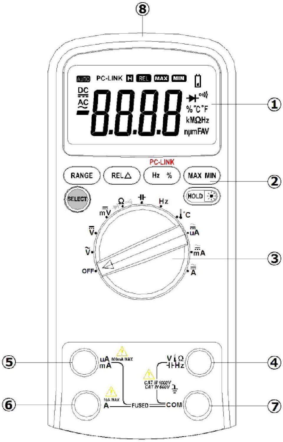
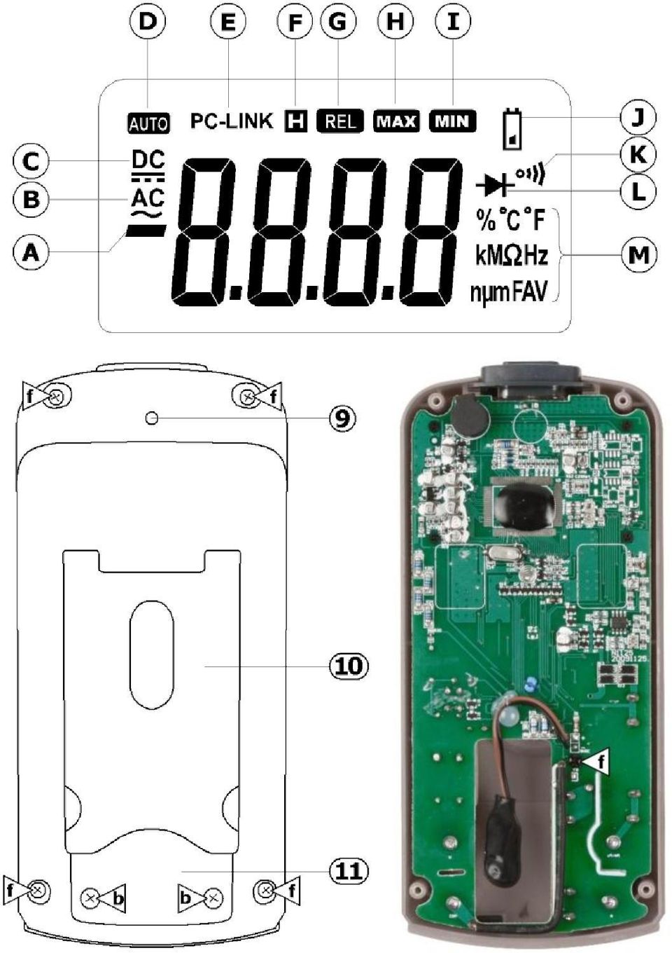
7 CAT IV and up to 1000V in CAT III. 5. Pollution degree IEC specifies different types of pollution environments, for which different protective measures are necessary to ensure safety. Harsher environments require more protection, and the protection against the pollution which is to be found in a certain environment depends mainly on the insulation and the enclosure properties. The pollution degree rating of the DVM indicates in which environment the device may be used. Pollution No pollution or only dry, nonconductive pollution occurs. The pollution degree 1 has no influence. (only to be found in hermetically sealed enclosures) Pollution degree 2 Pollution degree 3 Pollution degree 4 Only nonconductive pollution occurs. Occasionally, temporary conductivity caused by condensation is to be expected.(home and office environments fall under this category) Conductive pollution occurs, or dry nonconductive pollution occurs that becomes conductive due to condensation that is to be expected. (industrial environments and environments exposed to outside air - but not in contact with precipitation) The pollution generates persistent conductivity caused by conductive dust or by rain or snow. (exposed outdoor environments and environments where high humidity levels or high concentrations of fine particles occur) Warning: This device was designed in accordance with EN pollution degree 2. This implies that certain restrictions in use apply that are related to pollution which can occur within the environment of use. Refer to the table above. This device is only suitable for measurements in Pollution degree class 2 environments. 6. Description Refer to the illustrations on pages 2 and 3 of this manual. 6.1 Multi-meter 1 LCD 7 COM terminal 2 function keys 8 PC link connector (DVM4100 only) 3 rotary switch 9 not used 4 VΩ Hz terminal 10 foldable stand 5 µama terminal 11 battery compartment 6 10A terminal 6.2 Display No. Symbol Meaning A B C D E AUTO indicates negative readings indicator for AC voltage or current indicator for DC voltage or current the meter is in the Auto range mode (automatically selects the range with the best resolution) PC-LINK the meter is in the data transmission mode (DVM4100 only) F H the meter is in Data Hold mode.
 Pollution degree 2 Pollution degree 3 Pollution degree 4 Only nonconductive pollution occurs.")
8 G REL the meter is in Relative Measurement mode. H MAX maximum data is displayed I MIN minimum data is displayed J K low battery indication the meter is in Continuity Check mode. L M % C F KM Hz nμmfav the meter is in Diode Test mode. Measurement units 6.3 Function keys key function Meaning SELECT RANGE REL Hz % MAX MIN Switch between resistance measurement, diode test and Ω continuity test. ma µa Switch between DC and AC current. power off all V~, V=, Ω, ma, µa all except Hz/Duty V~, A, ma, µa all except Hz/Duty and Press and hold while switching on to disable sleep mode. Press to enter/exit Data Hold mode. Press and hold for ±2s to switch the backlight on/off. Press to enter manual ranging mode and to scroll through the different ranges. Press and hold for ±2s to return to auto-ranging. Press to enter/exit relative measurement mode. Press to start frequency counter, press again to enter Duty Cycle (load factor). Press again to exit frequency counter. Press and hold while switching on the meter to start data transmission (DVM4100 only). Press to measure maximum value, press again to measure minimum values. Press and hold for ±2s to return to normal measuring mode.

9 6.4 Mode description DATA HOLD mode In Data Hold mode, the display is not longer updated. Press the HOLD button to enter Data Hold mode. H is shown on the display [F]. When Data Hold mode is enabled in auto range mode, the meter switches to manual ranging mode. To exit Data Hold mode, press the RANGE or HOLD button Manual / Auto range mode The meter has both manual and auto range options. In the auto range mode, the meter selects the best range for the input detected. This allows you to switch test points without having to reset the range. When the meter is in the auto range mode, AUTO is displayed [D]. In the manual ranging mode, the range must be selected manually. This allows the user to override auto range and lock the meter in a specific range. The meter defaults to auto range mode for measurement functions that have more than one range. To enter and exit the manual range mode press the RANGE button. Press successively to scroll through the available ranges. To exit the manual ranging mode, press and hold down RANGE key for two seconds. The meter returns to the auto range mode and AUTO is displayed. Sleep mode The Meter enters the "sleep mode" and blanks the display if the meter is on but not used for 30 minutes. Press the HOLD button or rotate the rotary switch to wake the meter up. To disable Sleep mode, hold down the SELECT key while turning the meter on. Relative measurement mode Relative measurement mode is available during all functions except frequency. To enter and exit the relative measurement mode, start the measurement. Press REL key to store the measured value and activate the relative measurement mode. The difference between the reference value and subsequent reading is displayed. REL is shown on the display [G]. Press REL key for more than 2 seconds to return the meter to normal operation. 6.5 PC Link (model DVM4100 only) PC Link is only compatible with Windows XP, Vista and Windows 7 32 & 64 bit. The DVM4100 has a serial data output function. Before continuing the necessary USB driver and software must be installed on the PC. Insert the included CD ROM into a suitable PC. Locate and open the file README.pdf for the installation procedure (English only). Follow the instructions on the screen Notes: First install the PC-link software followed by the USB driver, than restart the PC. log in on the PC as administrator. For Vista/Windows 7 systems, disable the UAC (User Account Control) (via Control Panel System and Security Action Center User Account Control settings -> Never notify.) Connect the meter to a USB port of a PC using the included data cable. Press and hold the Hz % button while turn on the meter, the meter enter PC-Link mode. T the symbol PC-LINK will appear on the LCD [E] and the serial data output function is active. Notes: It is not possible to enter PC LINK during measurement; the meter must be switched off first. To disable the auto power off function, simultaneously hold down the SELECT and Hz% button while turning the meter on. Run the PC-LINK software, click the SET menu. Select the System Set. Then select the proper COM port in the Serial Port Select. To determine the COM port, go to Device Manager:

10 Right-click the My Computer icon on the Windows desktop, and then click Properties. Click the Hardware tab and then click Device Manager. Scroll through the list of installed devices and locate the Ports (Com and LPT) entry. Click the plus (+) next to this entry to view the installed ports, If no errors occurred, the Prolific USB-to-Serial COM Port (COM x) will appear, COM x is the port, with x = a specific number. Select the default sampling rate or set a desired sampling rate. Now press the Start in the PC-LINK SOFT to measure and view the real-time data or graph in the software interface. To disable the serial data output function, switch the meter OFF. More information about the PC-LINK SOFT can be found in the help-file of the software. 7. Operating instructions Risk of electric shock during operation. Be very careful when measuring live circuits. Before measuring, always make sure the meter and/or test probes are not damaged and verify the connections, selected function and range. Never exceed the limit value for protection. This limit value is listed separately in the specifications for each range of measurement. Do not touch unused terminals when the meter is linked to a circuit which is being tested. Only use the meter in the indicated overvoltage/installation category. Never measure voltages that might exceed the indicated category values. When a measuring range is unknown, always select the highest possible range and lower to the appropriate range. Disconnect the test leads from the tested circuit before rotating the range selector in order to change functions. When carrying out measurements on a TV set or switching power circuits, always remember that high amplitude voltage pulses at the test points might damage the meter. Always be careful when working with voltages above 60Vdc or 30Vac rms. Keep your fingers behind the probe barriers at all times during measurement. Do not measure current in circuits with voltages > 1000V. Never perform resistance, diode or continuity measurements on live circuits. Make sure all capacitors in the circuit are depleted. 7.1 Voltage measurements Do not measure circuits where voltages > 600V CAT IV or > 1000V CAT III may reside. Always be careful when working with voltages above 60Vdc or 30Vac rms. Keep your fingers behind the probe barriers at all times during measurement. Do not touch unused terminals when the meter is linked to a circuit which is being tested. Connect the red test lead to the "VΩ Hz " jack and the black lead to the "COM" jack. Set the rotary switch to V for DC measurements or to V for AC measurements. Press the RANGE button to manually select the range. Connect the test probes to the source being measured. The measured value appears on the LCD display. Notes: For DC-measurements, when a negative polarity is present at the red test lead, the indicated value is preceded by a - sign.

11 When measuring DC offset of an AC voltage, measure the AC voltage first and select a range for the DC offset equal to or higher than the AC range to increase accuracy. 7.2 Resistance measurements Do not perform resistance measurements on live circuits. Connect the red test lead to the "VΩ Hz " jack and the black lead to the "COM" jack. Set the rotary switch to ". When necessary, press the SELECT button until MΩ is shown on the display. Press the RANGE button to manually select the range. Connect the test probes to the source being measured. The measured value appears on the LCD display. Notes: o Never perform resistance measurements on a live circuit and make sure all capacitors are completely depleted. o To increase accuracy when measuring low resistance values, first hold the tips of the measuring probes together to determine the resistance value of the test leads. Subtract this value from the measured value of the circuit. o For resistance measurements above 10MΩ the meter needs a few seconds to stabilize the read-out. o Should the measured resistance exceed the current range or in case of an open circuit, the display will show OL. 7.3 Continuity measurements Do not perform continuity measurements on live circuits. Connect the red test lead to the "VΩ Hz " jack and the black lead to the "COM" jack. Set the rotary switch to. Press the SELECT button to select continuity test. Connect the test probes to the source being measured. When the measured resistance is less than 40Ω a continuous beep is produced and the resistance value is showed on the display. Should the measured resistance exceed the current range or in case of an open circuit, the display will show OL. Nota: Never perform continuity measurements on a live circuit and make sure all capacitors are completely depleted. 7.4 Diode measurements Do not perform diode measurements on live circuits. Connect the red test lead to the "VΩ Hz " jack and the black lead to the "COM" jack. Set the rotary switch to. Press the SELECT button to select diode test. Connect the red test probe to the anode of the diode and the black test probe to the cathode. The meter shows the forward voltage drop of the diode. When the diode is connected with a reversed polarity, the display shows OL. Notes: o Never perform diode measurements on a live circuit and make sure all capacitors are completely depleted. o Measuring diodes that are part of a circuit might produce faulty results. Consider unmounting from the circuit.

12 7.5 Capacitance measurements Do not perform capacitance measurements on live circuits. Connect the red test lead to the "VΩ Hz " jack and the black lead to the "COM" jack. Set the rotary switch to. Press the RANGE button to manually select the range. Connect the test probes to the capacitor and read its value from the display. Notes: o It takes a few seconds before the meter shows the result. This is normal behavior (e.g µF range >30s). o To increase accuracy when measuring low capacitance values (<4nF), first hold the tips of the measuring probes together to determine the capacitance value of the test leads. Subtract this value from the measured value of the circuit. o Never perform capacitance measurements on a live circuit and make sure all capacitors are completely depleted. 7.6 Frequency measurements Do not perform frequency measurements in circuits with voltages > 1000V. Always be careful when working with voltages above 60Vdc or 30Vac rms. Keep your fingers behind the probe barriers at all times during measurement. Do not touch unused terminals when the meter is linked to a circuit which is being tested. Connect the red test lead to the "VΩ Hz " jack and the black lead to the "COM" jack. Set the rotary switch to Hz. Press the RANGE button to manually select the range. Connect the test probes to the circuit and read the measured value from the LCD. Notes: o The frequency can also be measured during AC voltage/current measurement. Start the measurement and press the HZ % button to measure the frequency or duty cycle. o Use a shielded cable for measuring small signals in a noisy environment. 7.7 Temperature measurements Do not touch any live parts with the temperature measuring probe. Set the rotary switch to the C range. When no temperature measuring probe is connected, the current environmental temperature is displayed. Place the adaptor socket between the VΩ Hz and the COM jack (align + with VΩ Hz ). Plug the thermocouple (type K) into the adaptor socket (align + with + ). Hold the tip of the temperature probe against the object under test. Read the temperature on the LCD. 7.8 Current Measurements Do not measure current in circuits with voltages > 1000V Current measuring jack µa/ma max. 600mA. For currents up to 10A use the 10A jack. Always be careful when working with voltages above 60Vdc or 30Vac rms. Keep your fingers behind the probe barriers at all times during measurement.
, first hold the tips of the measuring probes together to determine the capacitance value of the test leads.")
13 For measurements up to 600mA: connect the red test lead to the "µama" jack and the black lead to the "COM" jack. For measurements up to 10A: connect the red test lead to the "10A" jack and the black lead to the "COM" jack. Set the rotary switch to the µa range for measurements up to 600µA (only when test probe is connected to the µama jack). Set the rotary switch to the ma range for measurements up to 600mA (only when test probe is connected to the µama jack). Set the rotary switch to the A range for measurements up to 10A (only when test probe is connected to the 10A jack). Press the SELECT button to select DC current (DCA) or AC current (ACA) mode. Connect the test probes in series with the circuit. Read the measured value from the display. Notes: o for DC-current measurements, when a negative polarity is present at the red test lead, the indicated value is preceded by a - sign. o The µama-range is protected against over current with a F630mA 1000V fuse, the 10A-range is protected against over current with a F10A 1000V fuse. 8. Maintenance Do not replace internal parts yourself. Replace damaged or lost accessories by identical ones with the same specifications. Order spare accessories e.g. test probes at your dealer. a. General maintenance Wipe the device regularly with a moist, lint-free cloth. Do not use alcohol or solvents. b. Fuse Replacement Switch off the multi-meter, disconnect the test leads from the test points and remove the test leads from the measuring jacks before replacing the batteries or fuses. Refer to the illustration on pages 3 of this manual. Remove the 4 screws at the back (indicated with open the meter. in the illustration) and gently Remove the screw that holds the PCB in place (indicated with in the illustration) and gently lift the PCB. Remove the fuse from the fuse holder and replace it with a new fuse of the same type and with the same specifications (F630mA/1000V - Ø10.3x38mm, F10A/1000V - Ø10.3x38mm). Close the meter meticoulsly. c. Battery Replacement To avoid false readings, which could lead to possible electric shocks or personal injury, replace the battery as soon as the battery indicator appears. Switch off the multi-meter, disconnect the test leads from the test points and remove the test leads from the measuring jacks before replacing the batteries or fuses. Refer to the illustration on pages 3 of this manual. Remove the 2 screws at the back of the meter (indicated with in the illustration) and gently open the battery compartment. Replace the battery (9V 6LF22). Do not use rechargeable batteries. Insert following the right polarity. Close the battery compartment and reseat the screws.
.")
14 9. Technische specificaties This device is not calibrated when purchased! Regulations concerning environment of use: Use this meter only for measurements in CATI, CATII, CAT III (<1000V) and CAT IV (<600V) environments (see 4) Use this meter only in a pollution degree 2 environment (see 5) Ideal working conditions include: Temperature: 18 to 28 C (64 F to 82 F) relative humidity: max. 75% altitude: max. 2000m (6560ft) 9.1. General Max. Voltage Display Fuse Protection Temperature coefficient Power Supply Ranging Method Polarity Indication Overrange Indication Battery-Low Indication Operating Temperature Storage Temperature Dimensions Weight 9.2. DC Voltage 600V CAT IV, 1000V CAT III 3 5/6- digit LCD, 2 to 3 samples/sec. µa/ma-range: 630mA/1000V (Ø10.3x38mm) 10A-range: 10A/1000V (Ø10.3x38mm) 0.1x(specified accuracy)/ C (<18 C or >28 C) 9V NEDA F22 006P (incl.) manual/automatic " - " is displayed "OL" is displayed automatically " " is displayed 0 C to 40 C (32~122 F) (<80%RH, <10 C non condensing) -10 C to 60 C (14~140 F) (<70%RH, battery removed) 190x90x40mm ±500g (incl. battery) Range Resolution Accuracy 600mV 100µV (0.5% of rdg + 5 digits) 6V 1mV 60V 10mV (0.8% of rdg + 5 digits) 600V 100mV 1000V 1V (1.0% of rdg +2 digits) Input Impedance: >10M for all ranges 9.3. AC Voltage Range Resolution Accuracy 600mV 100µV 6V 1mV 60V 10mV (1.0% of rdg + 5 digits) 600V 100mV 1000V 1V (1.5% of rdg +2 digits) Input Impedance: >10M for all ranges Frequency Range: 40 to 400Hz Overload protection: 1000Vdc or ac rms DC Current Range Resolution Accuracy 600µA 0.1µA 6mA 1µA 60mA 10µA (1.5% of rdg + 3 digits) 600mA 0.1mA 6A 1mA (1.5% of rdg +5 digits)

15 10A 10mA When measuring currents > 6A, max. 15s continuous measurement followed by a 15 minutes break between 2 measurements. Overload Protection: 600mA range F0.63A/1000V 10A range fuse F10A/1000V 9.5. Resistance Range Resolution Accuracy (0.5% of rdg + 3 digits) 6k 1 60k k 100 (0.5% of rdg + 2 digits) 6M 1k 60M 10k (1.5% of rdg + 5 digits) Note: in range 600Ω, short circuit test leads to determine lead resistance, than subtract this value from the measured value Diode and audible continuity test Range parameters Built-in buzzer sounds if resistance < 30Ω Forward test current(dc): ± 1mA Reversed test voltage: ± 1.5Vdc 9.7. Capacitance Range Resolution Accuracy 60nF 10pF <10nF: ±(5.0% of (rdg - 50 digits) + 20 digits) >10nF: ±(3.0% of rdg + 10 digits) 600nF 100pF 6µF 1nF 60µF 10nF (5.0% of rdg +10 digits) 300µF 100nF 9.8. Temperature Range Resolution Accuracy -55 C ~ 0 C ±(5.0% of rdg + 4 C) 0.1 C 1 C ~ 400 C ±(1.0% of rdg + 3 C) 401 C ~ 1,000 C 1 C ±(2.0% of rdg) Note: thermocouple errors not included 9.9. Frequency Range 99.99Hz 999.9Hz 9.999kHz 99.99kHz kHz Resolution 0.01Hz 0.1Hz 1Hz 10Hz 100Hz Logic (1Hz~1MHz) ±(0.1% of rdg + 3 digits) Accuracy Linear (6Hz~10KHz) ±(0.05% of rdg + 8 digits) N.A. Use this device with original accessories only. Velleman nv cannot be held responsible in the event of damage or injury resulted from (incorrect) use of this device. For more info concerning this product and the latest version of this user manual, please visit our website The information in this manual is subject to change without prior notice. COPYRIGHT NOTICE This manual is copyrighted. The copyright to this manual is owned by Velleman nv. All worldwide rights reserved. No part of this manual may be copied, reproduced, translated or reduced to any electronic medium or otherwise without the prior written consent of the copyright holder.
 + 20 digits) >10nF: ±(3.0% of rdg + 10 digits) 600nF 100pF 6µF 1nF 60µF 10nF (5.")
16 GEBRUIKERSHANDLEIDING 1. Inleiding Aan alle ingezetenen van de Europese Unie Belangrijke milieu-informatie betreffende dit product Dit symbool op het toestel of de verpakking geeft aan dat, als het na zijn levenscyclus wordt weggeworpen, dit toestel schade kan toebrengen aan het milieu. Gooi dit toestel (en eventuele batterijen) niet bij het gewone huishoudelijke afval; het moet bij een gespecialiseerd bedrijf terechtkomen voor recyclage. U moet dit toestel naar uw verdeler of naar een lokaal recyclagepunt brengen. Respecteer de plaatselijke milieuwetgeving. Hebt u vragen, contacteer dan de plaatselijke autoriteiten betreffende de verwijdering. Dank u voor uw aankoop! Lees deze handleiding grondig voor u het toestel in gebruik neemt. Werd het toestel beschadigd tijdens het transport, installeer het dan niet en raadpleeg uw dealer. Raadpleeg de Velleman service- en kwaliteitsgarantie achteraan deze handleiding. 2. Gebruikte symbolen Dit symbool staat voor instructies lezen: Het niet lezen van deze instructies en de handleiding kan leiden tot beschadiging, letsel of de dood Dit symbool betekent gevaar: Gevaarlijke toestand of actie die kan leiden tot letsel of de dood Dit symbool betekent risico op gevaar/schade: Risico op het ontstaan van een gevaarlijke toestand of actie die kan leiden tot schade, letsel of de dood Dit symbool betekent aandacht, belangrijke informatie: Het niet in acht nemen van deze informatie kan leiden tot een gevaarlijke toestand AC (wisselstroom) DC (gelijkstroom) zowel wissel- als gelijkstroom Dubbele isolatie (class II-bescherming) Aarding Zekering Capaciteit (condensator) Diode Continuïteit Achtergrondverlichting
 niet bij het gewone huishoudelijke afval; het moet bij een gespecialiseerd bedrijf terechtkomen voor recyclage.")
17 3. Veiligheidsinstructies Volg de richtlijnen hieronder om een veilig gebruik te garanderen en alle functies van de meter ten volle te benutten. Respecteer tijdens het gebruik van de meter alle richtlijnen aangaande beveiliging tegen elektroshocks en verkeerd gebruik. De aangegeven limietwaarden mogen nooit overschreden worden WAARSCHUWING: Uit veiligheidsoverweging, lees de handleiding Opmerking: dit is de vertaling van de waarschuwing die zich bovenaan op de achterkant van het toestel bevindt. WAARSCHUWING: Om elektrische schokken te vermijden, verwijder de testsnoeren alvorens de behuizing te openen Om schade of verwonding te voorkomen, installeer een zekering met dezelfde volt/amp specificaties zoals aangeduid. Opmerking: dit is de vertaling van de waarschuwing die zich onderaan op de achterkant van het toestel bevindt. Vermijd koude, hitte en grote temperatuursschommelingen, Als het toestel van een koude naar een warme omgeving verplaatst wordt, laat het toestel dan eerst voldoende op temperatuur komen. Dit om meetfouten en condensvorming te vermijden. Bescherm het toestel tegen schokken. Vermijd brute kracht tijdens de bediening. Vervuilingsgraad 2-toestel, enkel geschikt voor gebruik binnenshuis! Stel dit toestel niet bloot aan stof, regen, vochtigheid en opspattende vloeistoffen. Niet geschikt voor industrieel gebruik. Zie 5 Vervuilingsgraad. Houd dit toestel uit de buurt van kinderen en onbevoegden. Elektrocutiegevaar tijdens het gebruik van deze multimeter. Wees voorzichtig tijdens het meten van een circuit onder spanning. Wees uiterst voorzichtig bij metingen > 60VDC of 30Vrms AC De gebruiker mag geen inwendige onderdelen vervangen. Vervang beschadigde of verloren accessoires enkel door accessoires van hetzelfde type of met dezelfde specificaties. Bestel reserveaccessoires zoals meetsnoeren bij uw dealer. Dit is een installatiecategorie CAT IV 600V / CAT III 1000V meetinstrument. Gebruik dit toestel nooit in een hogere CAT dan aangegeven. Zie 4 overspanning-/installatiecategorie. Lees deze bijlage en de handleiding grondig, leer eerst de functies van het toestel kennen voor u het gaat gebruiken. Om veiligheidsredenen mag u geen wijzigingen aanbrengen. Schade door wijzigingen die de gebruiker heeft aangebracht valt niet onder de garantie. Gebruik het toestel enkel waarvoor het gemaakt is. Bij onoordeelkundig gebruik vervalt de garantie. De garantie geldt niet voor schade door het negeren van bepaalde richtlijnen in deze handleiding en uw dealer zal de verantwoordelijkheid afwijzen voor defecten of problemen die hier rechtstreeks verband mee houden. Let erop dat de meter zich in de juiste stand bevindt alvorens deze te verbinden met het testcircuit. Meet niet aan circuits waarin spanningen kunnen voorkomen > 1000V (DC of rms AC)

18 Meet geen stroom in circuits met een spanning > 1000V Voer geen weerstand-, diode- of continuïteitsmetingen uit in circuits waarop spanning aanwezig is, of zou kunnen voorkomen. Controleer voor gebruik indien de meetsnoeren in goede staat verkeren. Hou tijdens metingen uw vingers achter de beschermingsrand van de meetpennen! Raak geen vrije meetbussen aan wanneer de meter met een circuit is verbonden. Schakel de meter uit en verwijder de testsnoeren vóór u de batterij of zekering vervangt. Let op bij metingen op circuits zoals tv s of schakelende voedingen, er kunnen spanningspieken voorkomen die de meter kunnen beschadigen 4. Overspanning-/installatiecategorie DMM s worden opgedeeld volgens het risico op en de ernst van spanningpieken die kunnen optreden op het meetpunt. Spanningspieken zijn kortstondige uitbarstingen van energie die geïnduceerd worden in een systeem door bvb. blikseminslag op een hoogspanningslijn. De bestaande categorieën volgens EN zijn: CAT I CAT II CAT III CAT IV Een CAT I meter is geschikt voor metingen op beschermde elektronische circuits die niet rechtstreeks verbonden zijn met het lichtnet, bvb. Elektronische schakelingen, stuursignalen Een CAT II meter is geschikt voor metingen in CAT I omgevingen en op enkelfasige apparaten die aan het lichtnet gekoppeld zijn door middel van een stekker en circuits in een normale huiselijke omgeving, op voorwaarde dat het circuit minstens 10m verwijderd is van een CAT III omgeving, en minstens 20m van een CAT IV omgeving. Bvb. Huishoudapparaten, draagbare gereedschappen... Een CAT III-meter is geschikt voor metingen in CAT I- en CAT IIomgevingen, alsook voor metingen aan enkel- en meerfasige (vaste) toestellen op meer dan 10 m van een CAT IV-omgeving, en metingen inof aan distributiekasten (zekeringkasten, verlichtingscircuits, elektrisch fornuis). Een CAT IV meter is geschikt voor metingen in CAT I, CAT II en CAT III omgevingen alsook metingen op het primaire toevoerniveau. Merk op dat voor metingen op kringen waarvan de toevoerkabels buitenshuis lopen (zowel boven- als ondergronds) een CAT IV meter moet gebruikt worden. Waarschuwing: Dit toestel is ontworpen conform EN installatie categorie CAT IV 600V / CAT III 1000V. Dit houdt bepaalde gebruiksbeperkingen in die te maken hebben met voltages en spanningpieken die kunnen voorkomen in de gebruiksomgeving, zie tabel hierboven. Dit toestel is geschikt voor metingen tot max. 1000V aan: Beschermde circuits die beveiligd of niet rechtstreeks verbonden zijn aan het lichtnet zoals bv. stuursignalen en metingen aan elektronica, circuits achter een scheidingstransformator Circuits rechtstreeks verbonden aan het lichtnet maar beperkt tot: o Metingen aan monofaseapparaten verbonden met het lichtnet door middel van een stekker (stopcontact) o Metingen aan monofaseapparaten en circuits rechtstreeks verbonden met het lichtnet in een gewone huiselijke omgeving op meer dan 10m van een CAT IV omgeving. (bvb. verlichtingskringen op meer dan 10m van de zekeringkast)

19 Metingen in-/aan laagspanningsborden (zekeringkast na de tellerkast) Metingen aan mono- en meerfaseapparaten en circuits uitgezonderd in een CAT IV-omgeving (bv. metingen aan stopcontacten, elektrisch fornuis, verlichtingskringen, busbars, zekeringen en automaten) Dit toestel is geschikt voor metingen tot max. 600V aan: Metingen aan distributieborden en buiteninstallaties. Hieronder vallen de tellerkast en toestellen/circuits buiten of los van de huiselijke omgeving zoals kringen in schuurtjes, tuinhuisjes en vrijstaande garages- of kringen verbonden via ondergrondse leidingen zoals tuinverlichting of vijverpompen. DIT TOESTEL IS NIET GESCHIKT VOOR METINGEN VAN/AAN: Spanningen hoger dan 1000V Stromen hoger dan 10A Dit toestel is enkel geschikt voor metingen tot max. 600V in een CAT IV omgeving en tot max. 1000V in een CAT III omgeving 5. Vervuilingsgraad IEC specificeert verschillende types vervuilinggraden welke bepaalde risico s met zich meebrengen. Iedere vervuilingsgraad vereist specifieke beschermingsmaatregelen. Omgevingen met een hogere vervuilingsgraad hebben een betere bescherming nodig tegen mogelijke invloeden van de verschillende types vervuiling die in deze omgeving kunnen voorkomen. Deze bescherming bestaat hoofdzakelijk uit aangepaste isolatie en een aangepaste behuizing. De opgegeven waarde van vervuilingsgraad geeft aan in welke omgeving dit apparaat veilig gebruikt kan worden. Vervuilingsgraad 1 Vervuilingsgraad 2 Vervuilingsgraad 3 Vervuilingsgraad 4 Omgeving zonder, of met enkel droge- niet geleidende vervuiling. De voorkomende vervuiling heft geen invloed (Komt enkel voor in uitzonderlijke omgevingen) Omgeving met enkel niet geleidende vervuiling, Uitzonderlijk kan condensatie voorkomen. (bv. huishoudelijke- en kantooromgeving) Omgeving waar geleidende vervuiling voorkomt, of droge niet geleidende vervuiling die geleidend kan worden door condensatie. (industriële omgevingen en omgevingen die blootgesteld worden aan buitenlucht zonder rechtstreeks contact met neerslag Omgeving waar frequent geleidende vervuiling voorkomt, bv. veroorzaakt door geleidend stof, regen of sneeuw (in openlucht en omgevingen met een hoge vochtigheidsgraad of hoge concentraties fijn stof) Waarschuwing: Dit toestel is ontworpen conform EN vervuilingsgraad 2. Dit houdt bepaalde gebruiksbeperkingen in die te maken hebben met de pollutie die kan voorkomen in de gebruiksomgeving, zie tabel hierboven. Dit toestel is enkel geschikt voor gebruik in omgevingen met vervuilingsgraad 2 classificatie 6. Omschrijving Raadpleeg de afbeelding op pagina 2 en 3 van deze handleiding. 6.1 Multimeter 1 lcd-scherm 7 COM-bus 2 functietoetsen 8 aansluiting PC link (enkel DVM4100) 3 draaischakelaar 9 niet gebruikt 4 VΩ Hz -bus 10 opvouwbaar statief

20 5 µama-bus 11 batterijvak 6 10A-bus 6.2 Display A B C Symbool negatieve waarde AC-stroom of spanning DC-stroom of spanning D AUTO automatische bereikinstelling E Omschrijving PC-LINK dataoverdracht (enkel DVM4100) F H bevriezing van de uitlezing G REL relatieve meting H MAX maximumwaarde I MIN minimumwaarde J K aanduiding zwakke batterij continuïteitsmeting L M % C F KM Hz nμmfav diodetest meeteenheden 6.3 Functietoetsen SELECT RANGE REL Hz % MAX MIN Functie Omschrijving Ω schakel tussen weerstand-, diode- en continuïteitsmeting ma µa schakel tussen DC- en AC-stroom houd ingedrukt tijdens inschakeling om stand-byfunctie uit uitschakeling te schakelen bevriezing van de uitlezing; houd ingedrukt om alle achtergrondverlichting in of uit te schakelen V~, V=, Ω, ma, µa alle uitg. Hz/Duty V~, A, ma, µa alle uitg. Hz/Duty, handmatige bereikinstelling; houd ingedrukt om naar automatische bereikinstelling terug te keren in- en uitschakelen relatieve meetfunctie frequentietelling, puls-pauzeverhouding houd ingedrukt tijdens inschakeling voor dataoverdracht (enkel DVM4100) maximum- of minimumwaarde houd ingedrukt om naar normale meetmodus terug te keren 6.4 Omschrijving functies Bevriezing van de uitlezing (DATA HOLD) Bij een bevroren uitlezing worden de waarden niet meer geüpdatet. Druk op HOLD. H verschijnt op de display [F]. De multimeter schakelt over naar handmatige bereikinstelling. Druk op HOLD of RANGE om de functie uit te schakelen.

21 Handmatige/automatische bereikinstelling In automatische bereikinstelling (AUTO) kiest de multimeter zelf het gepaste bereik volgens de gemeten waarde. De automatische instelling is de standaardinstelling voor elke functie met meer dan één bereik. In handmatige bereikinstelling moet u het bereik zelf instellen. Druk elke keer op RANGE en kies het gepaste bereik. Houd RANGE ingedrukt om de functie te verlaten. Op de display verschijnt opnieuw AUTO. Stand-by (SLEEP) De multimeter schakelt over naar stand-by 30 minuten na het laatste gebruik. Druk op HOLD of draai aan de draaischakelaar om de multimeter opnieuw in te schakelen. Houd tijdens het inschakelen van de multimeter SELECT ingedrukt om de standbyfunctie uit te schakelen. Relatieve metingen Voer de meting uit. Druk op REL om de gemeten waarde in het geheugen op te slaan. Voer de nieuwe meting uit. Het verschil tussen de referentiewaarde en de gemeten waarde verschijnt op de display samen met REL [G]. Houd REL ingedrukt om de functie uit te schakelen. 6.5 PC Link (enkel DVM4100) PC-Link is alleen compatibel met Windows XP, Vista en Windows 7 32 & 64 bit. Installeer eerst de nodige driver en software op uw pc. Steek hiervoor de meegeleverde cd-rom in de cd-romdrive en open README.pdf. De installatieprocedure wordt automatisch opgestart. Volg de instructies (enkel in het Engels) op het scherm. Nota: Installeer eerst de PC Link-software en daarna de USB-driver. Herstart de pc. Log in op de pc als administrator. Vista/Windows 7: schakel UAC (User Account Control) uit (via configuratiescherm System and Security Action Center User Account Control settings -> Never notify). Sluit de multimeter aan op de USB-poort van de pc. Gebruik hiervoor de meegeleverde USB-kabel. Houd Hz % ingedrukt en schakel de multimeter in. De functie wordt ingeschakeld en PC-LINK verschijnt op de display [E]. Opmerkingen: De functie is niet inschakelbaar tijdens een meting, u moet de multimeter dus eerst uitschakelen. Houd tijdens het inschakelen van de mutlimeter SELECT en Hz% gelijktijdig ingedrukt om de automatische uitschakelfunctie uit te schakelen. Open de PC-LINK software en klik op SET. Selecteer System Set en daarna de correcte COM-poort onder Serial Port Select. Ga naar de Device Manager om de correcte poort te selecteren: Klik met de rechtermuisknop op My Computer en klik daarna op Properties. Klik op Hardware en op Device Manager. Scroll naar Ports (Com and LPT). Klik op (+) om de geïnstalleerde poorten weer te geven. Indien alles correct werd geïnstalleerd, ziet u Prolific USB-to- Serial COM Port (COM x) (COM x is de poort met x als het poortnummer). Selecteer de gewenste bemonsteringfrequentie. Druk op Start onder PC-LINK SOFT om de meting uit te voeren en de waarden in interface weer te geven. Schakel de multimeter uit om de functie te verlaten. Open het hulpbestand voor meer informatie over PC-LINK SOFT.
22 7. Gebruik Elektrocutiegevaar tijdens het gebruik van deze multimeter. Wees voorzichtig tijdens het meten van een circuit onder spanning. Controleer vooraleer te meten altijd indien de aansluitingen, de functie en het bereik correct zijn ingesteld en indien het toestel en/of de testsnoeren niet beschadigd zijn Overschrijd nooit de grenswaarden! Deze waarden worden vermeld in de specificaties van elk meetbereik. Raak geen ongebruikte ingangsbussen aan wanneer de meter gekoppeld is aan een schakeling die u aan het testen bent. Gebruik de meter enkel voor het meten in de aangeduide meetcategorieinstallaties en meet geen voltages die de aangeduide waarden kunnen overschrijden. Indien u niet zeker bent van het te meten bereik, kies dan eerst de hoogste stand en ga over naar een lagere instelling indien nodig. Koppel de testsnoeren los van het meetcircuit vooraleer u een andere functie kiest d.m.v. de draaischakelaar. Let op bij metingen op circuits zoals tv s of schakelende voedingen, er kunnen spanningspieken voorkomen die de meter kunnen beschadigen. Wees uiterst voorzichtig wanneer u werkt met voltages boven 60Vdc of 30Vac rms. Houd tijdens metingen uw vingers te allen tijde achter de beschermingsrand van de meetpennen! Meet geen stroom in circuits met een spanning > 1000V Voer nooit weerstandsmetingen, continuïteitstest, transistortest of diodetest uit op schakelingen die onder spanning staan. Vergewis uzelf ervan dat condensatoren die zich in het circuit bevinden ontladen zijn. 7.1 Spanningsmetingen Meet niet aan circuits waarin spanningen kunnen voorkomen > 600V CAT IV of 1000V CAT III. Wees uiterst voorzichtig wanneer u werkt met voltages boven 60Vdc of 30Vac rms. Houd tijdens metingen uw vingers te allen tijde achter de beschermingsrand van de meetpennen! Raak geen aansluitbussen aan tijdens de meting Koppel het zwarte meetsnoer met de COM- en het rode meetsnoer met de VΩ Hz -bus. Plaats de draaischakelaar op het V voor gelijkspanningsmetingen of op V voor wisselspanningmetingen. Druk op RANGE om het bereik manueel in te stellen. Verbind de meetsnoeren met het te meten circuit. De gemeten spanning kan afgelezen worden op de display. Nota: Bij gelijkspanningsmetingen wordt een negatieve polariteit van de gemeten spanning aan het rode meetsnoer weergegeven d.m.v. het - teken vóór de weergegeven waarde. Bij het meten van de DC offset van AC-spanning, meet eerst de AC-spanning en selecteer een bereik gelijk aan of groter dan de AC-spanning. 7.2 Weerstandsmetingen Voer geen weerstandsmetingen uit in circuits waarop spanning aanwezig is, of zou kunnen voorkomen Koppel het zwarte meetsnoer met de COM- en het rode meetsnoer met de VΩ Hz -bus.
23 Plaats de draaischakelaar op ". Indien nodig, druk op SELECT tot MΩ op de display verschijnt. Druk op RANGE om het bereik manueel in te stellen. Verbind de meetsnoeren met het te meten circuit. De gemeten weerstand kan afgelezen worden op het display. Nota s: o Zorg ervoor dat bij weerstandsmetingen geen spanning meer op de schakeling staat en dat alle condensatoren volledig ontladen zijn. o Om een zo nauwkeurig mogelijke lage weerstandswaarde te verkrijgen, verbind eerst de meetpennen met elkaar. Onthoud de afgelezen weerstandswaarde van de meetsnoeren. Trek deze af van de gemeten weerstandswaarde van het circuit. o Voor weerstanden boven 10MΩ heeft de meter enkele seconden nodig om de uitlezing te stabiliseren. o Indien de weerstand groter is dan het meetbereik of bij een open circuit word OL weergegeven op het scherm 7.3 Continuïteitstest/Doorverbindingtest Voer geen continuïteitsmeting uit in circuits waarop spanning aanwezig is, of zou kunnen voorkomen Koppel het zwarte meetsnoer met de COM- en het rode meetsnoer met de VΩ Hz -bus. Plaats de draaischakelaar op. Druk op SELECT om de continuïteitstest in te stellen. Verbind de meetsnoeren met het te testen circuit. Als de weerstand minder dan 40Ω bedraagt, is wordt een continue pieptoon weergegeven, alsook kan de weerstandswaarde afgelezen worden van het scherm. Indien de weerstand groter is dan het meetbereik of bij een open circuit wordt OL weergegeven op het scherm Nota: Zorg ervoor dat bij continuïteitstest geen spanning meer op de schakeling staat en dat alle condensatoren volledig ontladen zijn 7.4 Diodetest Voer geen diodemeting uit in circuits waarop spanning aanwezig is, of zou kunnen voorkomen Koppel het zwarte meetsnoer met de COM- en het rode meetsnoer met de VΩ Hz -bus. Plaats de draaischakelaar op. Druk op SELECT om de diodetest in te stellen. Verbind het rode meetsnoer met de anode van de diode en het zwarte meetsnoer met de kathode. De meter geeft de voorwaartse spanningsval van de diode weer. Bij verkeerde aansluitpolariteit verschijnt OL op het scherm. Nota s: o Zorg ervoor dat bij diodetest geen spanning meer op de schakeling staat en dat alle condensatoren volledig ontladen zijn o Meten van diodes die zich in een circuit bevinden kan foute resultaten opleveren, het is best de diodes los te koppelen van het meetcircuit. 7.5 Capaciteitsmetingen Voer geen capaciteitsmeting uit in circuits waarop spanning aanwezig is, of zou kunnen voorkomen Koppel het zwarte meetsnoer met de COM- en het rode meetsnoer met de VΩ Hz -bus. Plaats de draaischakelaar op.
24 Druk op RANGE om het bereik manueel in te stellen. Verbind de meetsnoeren met de te meten condensator en lees de waarde van het scherm af. Nota s: o De meter geeft de waarde pas na enkele seconden weer. Dit is absoluut normaal (bv µF bereik >30s). o Om nauwkeurigere metingen onder 4nF te verkrijgen, verbind eerst de meetpennen met elkaar. Onthoud de afgelezen capaciteitswaarde. Trek deze af van de gemeten capaciteitswaarde van het circuit. o Zorg ervoor dat bij de capaciteitstest geen spanning meer op de schakeling staat en dat alle condensatoren volledig ontladen zijn. 7.6 Frequentiemetingen Meet geen frequentie in circuits met een spanning > 1000V Wees uiterst voorzichtig wanneer u werkt met voltages boven 60Vdc of 30Vac rms. Houd tijdens metingen uw vingers te allen tijde achter de beschermingsrand van de meetpennen! Raak geen aansluitbussen aan tijdens de meting Koppel het zwarte meetsnoer met de COM- en het rode meetsnoer met de VΩ Hz -bus. Plaats de draaischakelaar op Hz. Druk op RANGE om het bereik manueel in te stellen. Verbind de meetsnoeren met het circuit en lees de gemeten waarde van het lcdscherm af. Nota s: o U kunt de frequentie ook meten tijdens het meten van een AC-stroom of -spanning. Start de meting en druk op Hz%. o Gebruik een afgeschermde kabel voor het meten van kleine signalen in een storingsgevoelige omgeving. 7.7 Temperatuurmetingen Raak geen delen aan die onder spanning zouden kunnen staan met de temperatuurmeetsonde. Stel de draaischakelaar in op het C-bereik. Als geen temperatuurmeetsonde is aangesloten is de huidige omgevingstemperatuur af te lezen op het scherm. Plaats de adapter in de VΩ Hz - en de COM-bus (+ met VΩ Hz ). Steek het thermokoppel in de adapter (+ met +). Raak het te meten object aan met de tip van de sonde van het thermokoppel. Lees de waarde van het lcd-scherm af. 7.8 Stroommetingen Meet geen stroom in circuits met een spanning > 1000V Stroommetingen µama-aansluiting tot max. 600mA, voor stroommetingen tot max. 10A gebruik de 10A-aansluiting Wees uiterst voorzichtig wanneer u werkt met voltages boven 60Vdc of 30Vac rms. Hou tijdens metingen uw vingers te allen tijde achter de beschermingsrand van de meetpennen! Koppel het zwarte meetsnoer met de COM- en het rode meetsnoer met de µamabus voor metingen tot max. 600mA Koppel het zwarte meetsnoer met de COM- en het rode meetsnoer met de 10Abus voor metingen tot max.10a
Electrical tests on Bosch unit injectors
 Valid for Bosch unit injectors with order numbers 0 414 700 / 0 414 701 / 0 414 702 Parts Kit Magnet*: - F00H.N37.925 - F00H.N37.933 - F00H.N37.934 * For allocation to the 10-place Bosch order number,
Power supply Interference suppressed acc. to DIN EN /- 4, EN 55011, EN CI. B, power factor corrected Power factor BöSha LED driver
 Operating Instructions LED Mast Double Luminaire Callisto SC DB, incl. Inclination Adjustment, Single-Chip Technology (Please, read carefully before starting operation) Version: 16.01.2017 Model 369-M
Tube Analyzer LogViewer 2.3
 Tube Analyzer LogViewer 2.3 User Manual Stand: 25.9.2015 Seite 1 von 11 Name Company Date Designed by WKS 28.02.2013 1 st Checker 2 nd Checker Version history Version Author Changes Date 1.0 Created 19.06.2015
p^db=`oj===pìééçêíáåñçêã~íáçå=
 p^db=`oj===pìééçêíáåñçêã~íáçå= How to Disable User Account Control (UAC) in Windows Vista You are attempting to install or uninstall ACT! when Windows does not allow you access to needed files or folders.
Electrical testing of Bosch common rail piezo injectors
 Applies to generation CRI 3: Bosch 10-position order number 0 445 115 = CRI 3-16 (CRI 3.0) 1600 bar 0 445 116 = CRI 3-18 (CRI 3.2) 1800 bar 0 445 117 = CRI 3-20 (CRI 3.3) 2000 bar Tools required: Hybrid
VIDEO CALL CAMERA G-VCAM-01
 VIDEO CALL CAMERA G-VCAM-01 EN AUS GUTEM GRUND ENGLISH 07-10 2 SAFETY AND INFORMATION Safety 7 This camera is designed to transmit video and audio signals. All other uses are expressly prohibited. 7 Protect
Word-CRM-Upload-Button. User manual
 Word-CRM-Upload-Button User manual Word-CRM-Upload for MS CRM 2011 Content 1. Preface... 3 2. Installation... 4 2.1. Requirements... 4 2.1.1. Clients... 4 2.2. Installation guidelines... 5 2.2.1. Client...
Electrical testing of Bosch common rail Injectors
 Electrical testing of Bosch common rail Injectors Contents: 1. Adapter cable for Hybridtester FSA 050 (article number 0 684 010 050 / 1 687 023 571) 2. Electrical testing of Bosch common rail solenoid
Electrical testing of Bosch common rail solenoid valve (MV) injectors
 injectors") Applies to MV injector, generation: -CRI 1.0 / 2.0 / 2.1 / 2.2 -CRIN 1 / 2 / 3, with K oder AK plug Bosch 10-position order number Bosch-Bestellnummer CRI: 0 445 110 xxx Bosch-Bestellnummer CRIN: 0 445
Applies to MV injector, generation: -CRI 1.0 / 2.0 / 2.1 / 2.2 -CRIN 1 / 2 / 3, with K oder AK plug Bosch 10-position order number Bosch-Bestellnummer CRI: 0 445 110 xxx Bosch-Bestellnummer CRIN: 0 445
MULTIMETER USER MANUAL
 0 6600 COUNTS MULTI FUNCTION MULTIMETER MULTIFUNCTIONELE MULTIMETER - 6600 COUNTS MULTIMÈTRE MULTIFONCTIONS - 6600 POINTS MULTÍMETRO MULTIFUNCIÓN - 6600 PUNTOS MULTIFUNKTIONSMULTIMETER - 6600 ZÄHLUNGEN
USB -> Seriell Adapterkabel Benutzerhandbuch
 USB -> Seriell Adapterkabel Benutzerhandbuch 1. Produkt Eigenschaften 1 2. System Vorraussetzungen 1 3. Treiber Installation (Alle Windows Systeme) 1 4. Den COM Port ändern 2 5. Einstellen eines RS232
p^db=`oj===pìééçêíáåñçêã~íáçå=
 p^db=`oj===pìééçêíáåñçêã~íáçå= Error: "Could not connect to the SQL Server Instance" or "Failed to open a connection to the database." When you attempt to launch ACT! by Sage or ACT by Sage Premium for
VGM. VGM information. HAMBURG SÜD VGM WEB PORTAL USER GUIDE June 2016
 Overview The Hamburg Süd VGM Web portal is an application that enables you to submit VGM information directly to Hamburg Süd via our e-portal Web page. You can choose to enter VGM information directly,
MU-307 A SAFETY INSTRUCTIONS SICHERHEITSHINWEISE FEATURES MERKMALE
 SAFETY INSTRUCTIONS Read all safety instruction before operating the amplifiers. 1. Install equipment as follow condition: - Install at flat place, not bending curved. - Do not install near the water and
CABLE TESTER. Manual DN-14003
 CABLE TESTER Manual DN-14003 Note: Please read and learn safety instructions before use or maintain the equipment This cable tester can t test any electrified product. 9V reduplicated battery is used in
VGM. VGM information. HAMBURG SÜD VGM WEB PORTAL - USER GUIDE June 2016
 Overview The Hamburg Süd VGM-Portal is an application which enables to submit VGM information directly to Hamburg Süd via our e-portal web page. You can choose to insert VGM information directly, or download
iid software tools QuickStartGuide iid USB base driver installation
 iid software tools QuickStartGuide iid software tools USB base driver installation microsensys Nov 2016 Introduction / Einleitung This document describes in short form installation of the microsensys USB
MANUAL_EN ANLEITUNG_DE PHONE SUITE SYNCHRONISATION SOFTWARE
 MANUAL_EN ANLEITUNG_DE PHONE SUITE SYNCHRONISATION SOFTWARE 2 PHONE SUITE MANUAL PHONE SUITE MANUAL 3 RESERVATION Technical Data is subject to change without notice. Changes, errors and misprints may not
Newest Generation of the BS2 Corrosion/Warning and Measurement System
 Newest Generation of the BS2 Corrosion/Warning and Measurement System BS2 System Description: BS2 CorroDec 2G is a cable and energyless system module range for detecting corrosion, humidity and prevailing
Digital Inclinometer. Elektronischer Neigungmesser. Bedienungsanleitung
 Digital Inclinometer Art.No. M541 Manual Page 2-4 Elektronischer Neigungmesser Art.Nr. M541 Bedienungsanleitung Seite 5-8 Please read the manual carefully before use ON/OFF button: push this button shortly,
ORION three-phase 2-250kVA
 ORION three-phase 2-250kVA Orion stabilizers are available for different ranges of input voltage fluctuation. Standard models offer a double input connection so that with the same unit two different input
Cameraserver mini. commissioning. Ihre Vision ist unsere Aufgabe
 Cameraserver mini commissioning Page 1 Cameraserver - commissioning Contents 1. Plug IN... 3 2. Turn ON... 3 3. Network configuration... 4 4. Client-Installation... 6 4.1 Desktop Client... 6 4.2 Silverlight
PROFIBUS-DP Repeater 1 to 1 and 1 to 5 with optional level converter module
 LSS PROFIBUS-DP Repeater 1 to 1 and 1 to 5 with optional level converter module The LSS PROFIBUS-DP repeaters 1 to 1 and 1 to 5 are used for coupling up to six PROFIBUS bus segments in RS 485 bus technology.
Anleitung zur Schnellinstallation TU3-SA 1.01
 Anleitung zur Schnellinstallation TU3-SA 1.01 Table of Contents Deutsch 1 1. Bevor Sie anfangen 1 2. Installation der Hardware 2 3. Zugriff auf die Festplatten des TU3-SA 4 Troubleshooting 5 Version 02.15.2011
Quick Installation Guide TBW-101UB TBW-102UB
 Quick Installation Guide TBW-101UB TBW-102UB Table of Contents Deutsch... 1. Bevor Sie anfangen... 2. Installation... 3. Cómo usar el adaptador Bluetooth... 1 1 2 4 Troubleshooting... 5 (Version 01.06.2006)
Datasheet. Page 1 of 7
 Features 20 Encoder Positions 4-way Joystick LED-Illumination high quality signal processing Benefits Tactile multi purpose application premium design Hall Effect technology Applications Multiple switch
Anleitung zur Verwendung des Update-Tools für
 English version see below (page 10) Anleitung zur Verwendung des Update-Tools für - KW DDC Steuergeräte - KW DDC WLAN Module - KW DLC Steuergeräte - KW DLC WLAN Module Bitte beachten Sie: jedes Steuergerät
Hama GmbH & Co KG Postfach Monheim/Germany Tel. +49 (0)9091/502-0 Fax +49 (0)9091/
9091/502-0 Fax +49 (0)9091/") www.hama.de Hama GmbH & Co KG Postfach 80 86651 Monheim/Germany Tel. +49 (0)9091/502-0 Fax +49 (0)9091/502-274 hama@hama.de www.hama.de 00062249-05.05 Multimedia Kit für/for Mercedes Command 2.0 00062249
www.hama.de Hama GmbH & Co KG Postfach 80 86651 Monheim/Germany Tel. +49 (0)9091/502-0 Fax +49 (0)9091/502-274 hama@hama.de www.hama.de 00062249-05.05 Multimedia Kit für/for Mercedes Command 2.0 00062249
Softwareupdate-Anleitung // Porty L 600 / Porty L 1200
 Softwareupdate-Anleitung // Porty L 600 / Porty L 1200 1 Softwareupdate-Anleitung // Porty L 600 / Porty L 1200 HENSEL-VISIT GmbH & Co. KG Robert-Bunsen-Str. 3 D-97076 Würzburg-Lengfeld GERMANY Tel./Phone:
Monitor VIS 3xx Kurzanleitung
 Monitor VIS 3xx Kurzanleitung 19.08.08 Art. Nr. 22261 Inhalt: 1. Spezifikationen...2 2. Tastenfunktionen...2 3. Menüführung und Einstellungen...3 Technik nach Maß Wöhler Monitor VIS 3xx 1. Spezifikationen
DVR / QuickQuide Adroid
 DVR 351.154/351.155 QuickQuide Adroid INSTRUCTION MANUAL GEBRUIKSAANWIJZING BEDIENUNGSANLEITUNG ENGLISH Setup IP-Camviewer Lite on IOS. 351.154 and 351.155. Start with searching the right app IP-camviewer
NEWSLETTER. FileDirector Version 2.5 Novelties. Filing system designer. Filing system in WinClient
 Filing system designer FileDirector Version 2.5 Novelties FileDirector offers an easy way to design the filing system in WinClient. The filing system provides an Explorer-like structure in WinClient. The
Overview thermostat/ temperature controller
 Thermostat TR-238 The Thermostat TR-238 is a electronic two-level controller for controlling of and in climate control units and vehicles. Voltage range (12V): Voltage range (24V): Control range: Hystereses:
STYLO MANUAL DEL USUARIO 3
 PEN-TYPE DIGITAL MULTIMETER DIGITALE PENMULTIMETER STYLO MULTIMÈTRE NUMÉRIQUE MULTÍMETRO DIGITAL TIPO BOLÍGRAFO DIGITALMULTIMETER IM STIFTDESIGN USER MANUAL GEBRUIKERSHANDLEIDING NOTICE D EMPLOI MANUAL
Quick Installation Guide TU2-ET100
 Quick Installation Guide TU2-ET100 Table of of Contents Contents... 1. Bevor Sie anfangen... 2. Installation... 1 1 2 Troubleshooting... 6 Version 08.30.2006 1. Bevor Sie anfangen Packungsinhalt TU2-ET100
ABB i-bus EIB. EIB Power Supply Units
 ABB i-bus EIB EIB Power Supply Units Product Range Overview EIB Power Supplies ABB STOTZ-KONTAKT GmbH, 2002 - SK 029 F 02 E Product Range Overview EIB Power Supplies! EIB Power Supply, 320 ma SV/S 30.320.5!
Installation Manual. Driver Installation USB-to-Serial Adapter WE2111. A en/de
 Installation Manual English Deutsch Driver Installation USB-to-Serial Adapter WE2111 A4012-1.0 en/de USB-to-Serial Adapter English 2 A4012-1.0 en/de USB-to-Serial Adapter 1 Installation in Windows 7...
ONLINE LICENCE GENERATOR
 Index Introduction... 2 Change language of the User Interface... 3 Menubar... 4 Sold Software... 5 Explanations of the choices:... 5 Call of a licence:... 7 Last query step... 9 Call multiple licenses:...
OPERATING INSTRUCTIONS Test pump ZG 5.1. and ZG 5.2.
 Elektromotoren und Gerätebau Barleben GmbH OPERATING INSTRUCTIONS Test pump ZG 5.1. and ZG 5.2. Elektromotoren und Gerätebau Barleben GmbH 2 Inhaltsverzeichnis Page 1 Use 4 2 Design features 4 2.1 Test
mobilcom-debitel SmartHome Schnell-Start-Anleitung Quick Start Guide
 mobilcom-debitel SmartHome Schnell-Start-Anleitung Quick Start Guide 1. Cube anschließen 1. Connect Cube n Schließen Sie den Cube an die Stromversorgung an. n Legen Sie die Batterien polungsrichtig in
3 IN 1 MULTIMETER - CABLE / LINE TESTE
 DVM10000 3 IN 1 MULTIMETER - CABLE / LINE TESTER 3-IN-1 MULTIMETER - KABEL- / LIJNTESTER MULTIMÈTRE 3 EN 1 - TESTEUR DE CÂBLE / DE LIGNE MULTÍMETRO 3 EN 1 - COMPROBADOR DE CABLES/LÍNEAS 3-IN-1-MULTIMETER
Installation Guide WLAN Interface
 Installation Guide 7106 7206 7010 WLAN Interface EN Installation Guide This guide explains how to install the Ethernet LAN card in your label printer. You should conult your dealer or distributor for more
Snap-in switch for switches PSE, MSM and MCS 30
 Product manual Snap-in switch for switches PSE, MSM and MCS 30 CONTENTS 1. PRODUCT DESCRIPTION 2. DATA AND DIMENSIONAL DRAWINGS 2.1. Technical Data 2.2. Dimensions of PSE with a Mounting Diameter 19 mm
Hazards and measures against hazards by implementation of safe pneumatic circuits
 Application of EN ISO 13849-1 in electro-pneumatic control systems Hazards and measures against hazards by implementation of safe pneumatic circuits These examples of switching circuits are offered free
Anleitung / User Manual
 3,5 USB HDD Enclosure Anleitung / User Manual Die Sicherung von Daten innerhalb der Festplatte ist nicht durch den Hersteller garantiert. Wir sind nicht verantwortlich für Datenverlust, fertigen Sie regelmäßig
v i r t u A L C O M P o r t s
 v i r t u A L C O M P o r t s (HO720 / HO730) Installieren und Einstellen Installation and Settings Deutsch / English Installieren und Einstellen des virtuellen COM Ports (HO720 / HO730) Einleitung Laden
EMCO Installationsanleitung / Installation instructions
 EMCO Installationsanleitung / Installation instructions Installationsanleitung Installation instructions Digitalanzeige digital display C40, FB450 L, FB600 L, EM 14D/17D/20D Ausgabe / Edition B 2012-03
C R 2025 C LOSE PUSH OPEN
 3V C R 2025 C LOSE PUSH OPEN ) ) ) 25 222 3V C R 2025 C LOSE PUSH OPEN 25 222 3V C R 2025 C LOSE PUSH OPEN 25 222 Den här symbolen på produkten eller i instruktionerna betyder att den elektriska
Der Adapter Z250I / Z270I lässt sich auf folgenden Betriebssystemen installieren:
 Installationshinweise Z250I / Z270I Adapter IR USB Installation hints Z250I / Z270I Adapter IR USB 06/07 (Laden Sie den Treiber vom WEB, entpacken Sie ihn in ein leeres Verzeichnis und geben Sie dieses
Bedienungsanleitung / Manual : LED-Nixie
 Bedienungsanleitung / Manual : LED-Nixie English please see below. Bei Neustart und gleichzeitig gedrückter Taste während der Versionsanzeige (halten bis Beep hörbar), erfolgt eine Zurücksetzung auf (Standard)
CB RADIO Service Manual AE 6890
 CB RADIO Service Manual AE 6890 Downloaded from www.cbradio.nl Technische Mitteilung zu AE 6890 Problem: Bei Montage einer schlecht geerdeten Antenne oder einer Antenne mit schlechtem SWR sehr nahe am
Duo - Swing XXL. Vor Montage und Benutzung unbedingt sorgfältig lesen und für spätere Zwecke aufbewahren.
 Vor Montage und Benutzung unbedingt sorgfältig lesen und für spätere Zwecke aufbewahren. Read these instructions carefully before use and assembly and keep for future reference! Lees deze instructies zorgvuldig
Anleitung zur Schnellinstallation TFM-561U
 Anleitung zur Schnellinstallation TFM-561U V1 Table of Contents Deutsch 1 1. Bevor Sie anfangen 1 2. Installation 2 Troubleshooting 5 Version 08.25.2010 1. Bevor Sie anfangen Packungsinhalt TFM-561U Treiber
Technische Information Stand : 08 / 2016
 Technische Information Stand : 08 / 2016 praxisorientierter handlicher Stromschleifen- Simulator und -Kalibrator UPS II - für die Messung und Simulation von 0 ( 4 )... 20 ( 21 ) ma, max. Bürde : 900 Ω
DVM1100 USER MANUAL GEBRUIKERSHANDLEIDING NOTICE D EMPLOI MANUAL DEL USUARIO BEDIENUNGSANLEITUNG
 AUTORANGING MULTIMETER MULTIMETER MET AUTOMATISCHE BEREIKINSTELLING MULTIMÈTRE À INSTAURATION DE GAMME AUTOMATIQUE MULTÍMETRO CON AJUSTE AUTOMÁTICO DEL RANGO MULTIMETER MIT AUTOMATISCHER BEREICHSEINSTELLUNG
Wandarm inkl. Montagebox und Netzteil Wall bracket incl. installation box and power supply
 Wandarm inkl. Montagebox und Netzteil Wall bracket incl. installation box and power supply Beschreibung und technische Daten: Wandarm (IP-66) mit Montagebox und eingebautem Netzteil Passend für SANTEC
Kuppeldach-Pavillon / Pavilion with dome-shaped roof / Koepeldak Paviljoen
 Pavilion with dome-shaped roof Koepeldak Paviljoen Vor Montage und Benutzung unbedingt sorgfältig lesen und für spätere Zwecke aufbewahren. Read these instructions carefully before use and assembly and
USB Treiber updaten unter Windows 7/Vista
 USB Treiber updaten unter Windows 7/Vista Hinweis: Für den Downloader ist momentan keine 64 Bit Version erhältlich. Der Downloader ist nur kompatibel mit 32 Bit Versionen von Windows 7/Vista. Für den Einsatz
SETUP TOOL. Bedienungsanleitung User s Manual
 Bedienungsanleitung User s Manual Bitte lesen Sie diese Anleitung vor der Inbetriebnahme sorgfältig durch Please read the instructions carefully before use 1. Eigenschaften Das Setup Tool ist ein speziell
Anleitung zur Schnellinstallation TFM-PCIV92A B1.21
 Anleitung zur Schnellinstallation TFM-PCIV92A B1.21 Table of Contents Deutsch 1 1. Bevor Sie anfangen 1 2. Installation 2 Troubleshooting 6 Version 05.11.2011 1. Bevor Sie anfangen Packungsinhalt ŸTFM-PCIV92A
Profi-Pavillon / Profi Pavilion / Profiteren Paviljoen
 Profi pavilion Profiteren paviljoen Vor Montage und Benutzung unbedingt sorgfältig lesen und für spätere Zwecke aufbewahren. Read these instructions carefully before use and assembly and keep for future
MQ964..GB MQ965..GB. en Operating instructions ar
 MQ964..GB MQ965..GB en Operating instructions ar MQ964-965GB-Uniklein_en-ar.book Seite 2 Donnerstag, 4. Dezember 2014 4:39 16 en English...........................................................3 ar...........................................................6.................................................
EL-21SY. 2 in, 1 out v1.3 HDMI Switcher OPERATION MANUAL
 EL-21SY 2 in, 1 out v1.3 HDMI Switcher OPERATION MANUAL Table of Contents 1. Introduction 1 2. Features 1 3. Package Contents 1 4. Operation Controls and Functions 2 4.1 Front Panel Diagram 2 4.2 Rear
Gartenschaukel RONDA / Garden swing RONDA / Tuin Schommelbank RONDA
 Garden swing RONDA Tuin Schommelbank RONDA Vor Montage und Benutzung unbedingt sorgfältig lesen und für spätere Zwecke aufbewahren. Read these instructions carefully before use and assembly and keep for
Parameter-Updatesoftware PF-12 Plus
 Parameter-Updatesoftware PF-12 Plus Mai / May 2015 Inhalt 1. Durchführung des Parameter-Updates... 2 2. Kontakt... 6 Content 1. Performance of the parameter-update... 4 2. Contact... 6 1. Durchführung
Quick Guide Home Network Mode
 Quick Guide Home Network Mode English > 1 German > 3 About the Home Network Mode EN Tivizen Nano & iplug normally work on their own created networks (whose SSID starts with tivizentv or iplug ) in which
Anleitung zur Schnellinstallation TEW-623PI 3.02
 Anleitung zur Schnellinstallation TEW-623PI 3.02 Table of Contents Deutsch 1 1. Bevor Sie anfangen 2. Installation 1 2 3. Verwendung des drahtlosen Adapters 4 Troubleshooting 5 Version 02.05.2010 1. Bevor
Hama GmbH & Co KG Postfach Monheim/Germany Tel. +49 (0)9091/502-0 Fax +49 (0)9091/
9091/502-0 Fax +49 (0)9091/") www.hama.de Hama GmbH & Co KG Postfach 80 86651 Monheim/Germany Tel. +49 (0)9091/502-0 Fax +49 (0)9091/502-274 hama@hama.de www.hama.de 00062248-05.05 Multimedia Kit für/for Audi Naviplus/ VW/Seat/Skoda
www.hama.de Hama GmbH & Co KG Postfach 80 86651 Monheim/Germany Tel. +49 (0)9091/502-0 Fax +49 (0)9091/502-274 hama@hama.de www.hama.de 00062248-05.05 Multimedia Kit für/for Audi Naviplus/ VW/Seat/Skoda
Datenblatt. Remote-I/O - u-remote UR20-4AO-UI or 4-wire connection; 16-bit resolution; 4 outputs
 2- or 4-wire connection; 16-bit resolution; 4 outputs The analogue output module controls up to 4 analogue actuators with +/-10 V, +/-5 V, 0...10 V, 0...5 V, 2...10 V, 1...5 V, 0...20 ma or 4...20 ma with
SEC-PH110. MANUAL (p. 2) Doorphone intercom. ANLEITUNG (S. 6) Gegensprechanlage. GEBRUIKSAANWIJZING (p. 16) Deurtelefoon intercom
 Doorphone intercom. ANLEITUNG (S. 6) Gegensprechanlage. GEBRUIKSAANWIJZING (p. 16) Deurtelefoon intercom") SEC-PH110 MANUAL (p. 2) Doorphone intercom ANLEITUNG (S. 6) Gegensprechanlage MODE D EMPLOI (p. 11) Interphone de porte GEBRUIKSAANWIJZING (p. 16) Deurtelefoon intercom MANUALE (p. 21) Citofono interfono
SEC-PH110 MANUAL (p. 2) Doorphone intercom ANLEITUNG (S. 6) Gegensprechanlage MODE D EMPLOI (p. 11) Interphone de porte GEBRUIKSAANWIJZING (p. 16) Deurtelefoon intercom MANUALE (p. 21) Citofono interfono
G-FLASH OBD-TOOL ANLEITUNG FÜR BMW & AMG-MODELLE INSTALLATIONSSOFTWARE & VORBEREITUNG
 INSTALLATIONSSOFTWARE & VORBEREITUNG 1. Laden Sie die Installationssoftware für das G-POWER G-Flash OBD-Tool von diesem Link https://tinyurl.com/mygeniusclient auf Ihren Laptop / PC herunter und führen
Certificate of conformity Generating unit, NS-protection
 Applicant: Product: Certificate of conformity Generating unit, NS-protection Schneider Electric Solar Inverters USA, Inc. 250 South Vasco Road Livermore, California 94551 USA Photovoltaic Inverter with
DVR / QuickQuide Adroid
 DVR 351.154/351.155 QuickQuide Adroid INSTRUCTION MANUAL GEBRUIKSAANWIJZING BEDIENUNGSANLEITUNG ENGLISH Setup IP-Camviewer Lite on Android. 351.154 en 351.155. Start with searching the right app IP-camviewer
Universe Square Suspension
 Universe Square Suspension NL Installatie handleiding DE Installationsanleitung EN Installation manual 1 NL Informatie / DE Information/ EN Information Veiligheidsinformatie Onderbreek altijd de stroomtoevoer
Pavilion TREND. Vor Montage und Benutzung unbedingt sorgfältig lesen und für spätere Zwecke aufbewahren.
 Vor Montage und Benutzung unbedingt sorgfältig lesen und für spätere Zwecke aufbewahren. Read these instructions carefully before use and assembly and keep for future reference! Lees deze instructies zorgvuldig
150Mbps Micro Wireless N USB Adapter
 150Mbps Micro Wireless N USB Adapter TEW-648UBM ŸAnleitung zur Schnellinstallation (1) ŸTroubleshooting (6) 1.11 1. Bevor Sie anfangen Packungsinhalt ŸTEW-648UBM ŸCD-ROM (Dienstprogramm & Bedienungsanleitung)
MultiPortSwitch. VGA Umschalter. Version 1.0 As of April 19 th 2004 Subject to change!
 MultiPortSwitch VGA Umschalter Version 1.0 As of April 19 th 2004 Subject to change! Document version: Version Date Name Comment 1.00 29.03.2004 J. Klein Compiled Distributed by: idata industrielle Datensysteme
Application Note. Import Jinx! Scenes into the DMX-Configurator
 Application Note Import Jinx! Scenes into the DMX-Configurator Import Jinx! Scenen into the DMX-Configurator 2 The Freeware Jinx! is an user friendly, well understandable software and furthermore equipped
TM RJ12-HUB. Benutzerhandbuch
 TM-75124 RJ12-HUB Benutzerhandbuch 2011 BioDigit Ltd. Alle Rechte vorbehalten. Die Vervielfältigung und/oder Veröffentlichung der Inhalte des vorliegenden Dokuments in jeglicher Form, einschließlich der
Anleitung zur Schnellinstallation TU3-S
 Anleitung zur Schnellinstallation TU3-S25 1.01 Table of Contents Deutsch 1 1. Bevor Sie anfangen 1 2. Installation der Hardware 2 3. Zugriff auf die Speichergeräte im TU3-S25 4 Troubleshooting 5 Version
DIGITAL MULTIMETER DETECTOR CONTACTO USER MANUAL
 DIGITAL MULTIMETER + NO CONTACT AC VOLTAGE DETECTOR DIGITALE MULTIMETER + CONTACTLOZE AC SPANNINGSDETECTOR MULTIMÈTRE NUMÉRIQUE + DÉTECTEUR DE TENSION CA SANS CONTACT MULTÍMETRO DIGITAL + DETECTOR DE TENSIÓNN
Anleitung zur Schnellinstallation TFM-560X YO.13
 Anleitung zur Schnellinstallation TFM-560X YO.13 Table of Contents Deutsch 1 1. Bevor Sie anfangen 1 2. Installation 2 Troubleshooting 6 Version 06.08.2011 1. Bevor Sie anfangen Packungsinhalt ŸTFM-560X
Where are we now? The administration building M 3. Voransicht
 Let me show you around 9 von 26 Where are we now? The administration building M 3 12 von 26 Let me show you around Presenting your company 2 I M 5 Prepositions of place and movement There are many prepositions
Bedienungsanleitung User Manual. PCMCIA Reader B1
 Bedienungsanleitung User Manual PCMCIA Reader B1 Einführung Introduction Vielen Dank, dass Sie sich für ein KOBIL Smart Card Terminal entschieden haben. Mit dem KOBIL PCMCIA Reader B1 haben Sie ein leistungsfähiges
Bedienungsanleitung Digitalmultimeter McCheck DM-312
 Bedienungsanleitung Digitalmultimeter McCheck DM-312 649-074 Einführung Geehrter Kunde, wir möchten Ihnen zum Erwerb Ihres neuen Digitalmultimeters gratulieren! Mit dieser Wahl haben Sie sich für ein Produkt
Can I use an older device with a new GSD file? It is always the best to use the latest GSD file since this is downward compatible to older versions.
 EUCHNER GmbH + Co. KG Postfach 10 01 52 D-70745 Leinfelden-Echterdingen MGB PROFINET You will require the corresponding GSD file in GSDML format in order to integrate the MGB system: GSDML-Vx.x-EUCHNER-MGB_xxxxxx-YYYYMMDD.xml
User Manual BB-anywhere
 User Manual BB-anywhere LOGIN PROCEDURE 1. Click the Start button, choose All Programs (right above the search box) and select BB-ANYWHERE from the Start menu: BB-anywhere in a nutshell Regardless whether
Benutzerhandbuch / User s Manual RUPS 2000 / -B1
 RUPS 2000 / RUPS 2000-B1 Benutzerhandbuch / User s Manual RUPS 2000 / -B1 Deutsch English Benutzerhandbuch RUPS 2000 / RUPS 2000-B1 Deutsch In diesem Benutzerhandbuch finden Sie eine Kurzanleitung zu Installation
Table of Cont 6. 2 General Information... 4 Purpose...4 Documentation...4 Scope of Supply...5 Technical Data Safety Regulations...
 2 General Information........................ 4 Purpose........................................4 Documentation................................4 Scope of Supply................................5 Technical
ATEX-Check list. Compiled by: Date: Signature: Acceptable practice at the determination of flash point: Closed cup according to ISO 2719
 Fire and explosion hazard ATEX 137 1999/92/EG und ATEX 95 2014/34/EU Danger assessment and determination of explosion protection zone for the test space as well as the installation site ATEX-Check list
Exercise (Part V) Anastasia Mochalova, Lehrstuhl für ABWL und Wirtschaftsinformatik, Kath. Universität Eichstätt-Ingolstadt 1
 Anastasia Mochalova, Lehrstuhl für ABWL und Wirtschaftsinformatik, Kath. Universität Eichstätt-Ingolstadt 1") Exercise (Part V) Notes: The exercise is based on Microsoft Dynamics CRM Online. For all screenshots: Copyright Microsoft Corporation. The sign ## is you personal number to be used in all exercises. All
Exercise (Part V) Notes: The exercise is based on Microsoft Dynamics CRM Online. For all screenshots: Copyright Microsoft Corporation. The sign ## is you personal number to be used in all exercises. All
Certificate of conformity Generating unit, NS-protection
 Certificate of conformity Generating unit, NS-protection Applicant: Product: Schneider Electric Solar Inverters USA, Inc. 250 South Vasco Road Livermore, California 94551 USA Photovoltaic Inverter with
Quick Installation Guide TE100-PCBUSR
 Quick Installation Guide TE100-PCBUSR Table of of Contents Contents Deutsch... 1. Bevor Sie anfangen... 2. Installation... 1 1 2 Troubleshooting... 3 Version 03.14.2006 1. Bevor Sie anfangen Packungsinhalt
Fundamentals of Electrical Engineering 1 Grundlagen der Elektrotechnik 1
 Fundamentals of Electrical Engineering 1 Grundlagen der Elektrotechnik 1 Chapter: Operational Amplifiers / Operationsverstärker Michael E. Auer Source of figures: Alexander/Sadiku: Fundamentals of Electric
SW-MOTECH GmbH & Co. KG Ernteweg 8/ Rauschenberg Germany. Tel. +49 (0) 64 25/ Fax +49 (0) 64 25/
 64 25/ Fax +49 (0) 64 25/") ATTENTION: The assembly of this product can be complicated and requires a good technical understanding. If you are not sure of how to do this, have a s pecialty garage perform the mounting and service.
ATTENTION: The assembly of this product can be complicated and requires a good technical understanding. If you are not sure of how to do this, have a s pecialty garage perform the mounting and service.
USB RS232 Converter IMPAC-Zubehör
 USB 2.0 - RS232 Converter IMPAC-Zubehör Installation Anleitung / Manual IMPAC - Spezialist für berührungslose Temperaturmessung IMPAC - Specialist in non-contact thermometry USB 2.0 RS232-Konverter, aktiv,
Laser LightmaXX CLUB 2.0 / 4.0 SERIES
 Seite 1 von 8 Laser LightmaXX CLUB 2.0 / 4.0 SERIES ACHTUNG! Seite 2 von 8 Laserschutzbestimmungen: Durch die starke Bündelung des Laserstrahls ist die gesamte Lichtenergie auf eine geringe Fläche konzentriert.
Markengeschichte. Hingabe unterscheidet uns. Hartnäckigkeit beschreibt uns.
 Bedienungsanleitung Mit unserem Glauben gehen wir voran. Mit unserer Leidenschaft steigern wir unsere Erfahrung. Vergessen die eigenen Fehlschläge, aber nicht das unerfüllte Potential. Die Leidenschaft
VN7640 FlexRay/CAN/LIN/Ethernet Interface Quick Start Guide. Version 1.1 English/Deutsch
 VN7640 FlexRay/CAN/LIN/Ethernet Interface Quick Start Guide Version 1.1 English/Deutsch Quick Start Guide VN7640 ENGLISH 1 ENGLISH 1.1 Installation Step by Step Procedure Please use the drivers from the