Montage-, Bedienungs- und Wartungsanleitung
|
|
|
- Erich Brinkerhoff
- vor 5 Jahren
- Abrufe
Transkript


1 Montage-, Bedienungs- und Wartungsanleitung en fr it ASSEMBLY, USER AND MAINTENANCE INSTRUCTIONS NOTICE DE MONTAGE, D'UTILISATION ET D'ENTRETIEN ISTRUZIONI DI MONTAGGIO, USO E MANUTENZIONE Art.-Nr.: Art.-Nr.: Art.-Nr.: Art.-Nr.: Art.-Nr.: Art.-Nr.: Stand: 1834
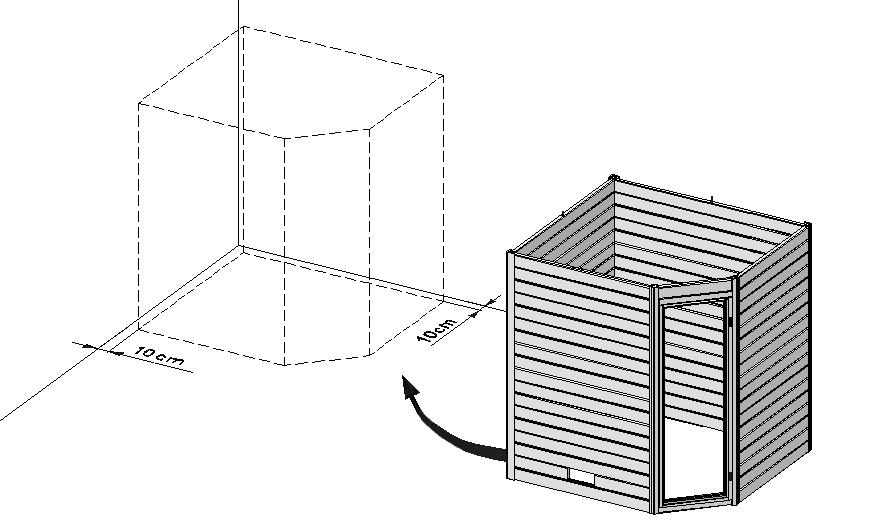
2 - de - Sehr geehrte Kundin, sehr geehrter Kunde, danke, dass Sie sich für ein weka Produkt entschieden haben. Lesen Sie diese Anleitung vor dem Aufbau bitte vollständig durch, um Montagefehler oder Beschädigungen zu vermeiden. WICHTIG! Prüfen Sie bitte sofort anhand der Packliste, ob das weka-produkt vollständig und unbeschädigt bei Ihnen angekommen ist. Bitte vernichten Sie die Packliste erst nach Ablauf der Garantiezeit. Diese Liste dient Ihnen zur Kontrolle auf Vollständigkeit der Einzelteile und ist mit dem Kaufbeleg aufzubewahren. Eventuelle Beanstandungen können mit Hilfe dieser Liste problemlos behoben werden. Die Pos.-Nummern der Packliste stimmen nicht mit den Pos.-Nummern folgender Montageanleitung überein. Wir empfehlen Ihnen die Montage mit 2 Personen durchzuführen. Zur Verhütung von Unfällen ist zu vermeiden, dass sich Kinder während der Montage in unmittelbarer Nähe befinden. Weiterentwicklungen im Sinne des technischen Fortschritts behalten wir uns vor. So können geringfügige Abweichungen in den Darstellungen entstehen. Verpackungsmaterial nicht einfach wegwerfen! Papier-, Pappe- und Wellpappeverpackungen, sowie Kunststoffverpackungsteile sollten in die entsprechenden Sammelbehälter gegeben werden. Werkstoff Holz Gesunde Äste, leichte Verfärbungen und kleine Risse sind für Holz charakteristisch, verleihen der Kabine sein natürliches Aussehen und sind kein Reklamationsgrund. Vor der Montage Für das Aufstellen der Kabine wird eine Mindestraumhöhe von 220 cm benötigt. Der Wandabstand muss mindestens 10 cm betragen. Der Fußboden muss eben und waagerecht sein, da es sonst zu Funktionsstörungen kommen kann. Am besten eignet sich ein trockener, gut belüftbarer Raum zur Nutzung Ihrer Kabine. Ein Stein- oder Fliesenboden erweist sich als praktische und zugleich attraktive Fußbodenvariante. Bei abweichendem Bodenbelag ist eine Steinplatte mit den Mindestmaßen 40 x 50 cm unter den Ofen zu legen, um Beschädigungen des Bodens zu vermeiden. Tipps zur Sicherheit Achten Sie darauf, dass sich keine Kinder unbeaufsichtigt in der Kabine aufhalten! Legen Sie keine Gegenstände auf dem Saunaofen ab. - BRANDGEFAHR! Vergewissern Sie sich bereits vor Beginn der Heizphase, daß sich keine brennbaren Gegenstände in der Nähe des Ofens befinden. Verwenden Sie Sauna - Aufgusskonzentrate nur in verdünnter Form. Hinweise über die richtige Handhabung finden Sie auf den Behältern. Verwenden Sie keine chemischen Klebstoffe im Inneren der Sauna, sondern allenfalls Holzleim. Nach Nutzung der Sauna lassen Sie diese bei geöffneter Tür auskühlen. Sorgen Sie stets für eine gute Durchlüftung des Raumes, in dem sich die Sauna befindet. Das Hinweisschild ist gut sichtbar in der Nähe des Saunaofens zu befestigen. Pflegehinweise Um lange Freude an der Kabine zu haben, sollte diese regelmäßig gereinigt werden. Das unübertroffen milde und bekömmliche Saunaklima wird durch die natürliche Diffusion und Speicherfähigkeit des Massivholzes erreicht. Daher darf keine Oberflächenbehandlung der Holzteile erfolgen. Bei längerer Nichtbenutzung empfehlen wir, die Kabine mindestens einmal im Monat eine halbe Stunde aufzuheizen. Damit wird eine unerwünschte Feuchtigkeitsaufnahme vermieden. Geringer Harzausfluss an der Holzoberfläche ist unvermeidbar. Die trockenen Harzrückstände können mit feinem Schleifpapier entfernt werden. 1
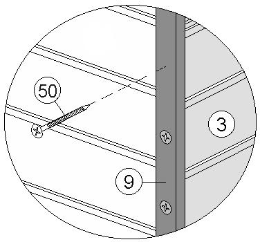
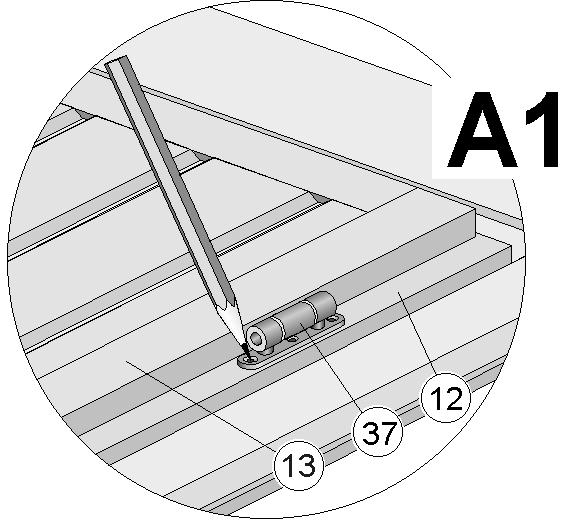
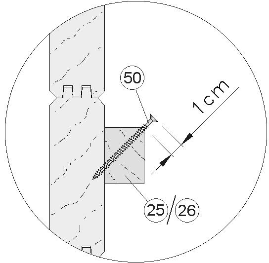
3 Elektroinstallation Die Elektroinstallation darf nur von einem zugelassenen Elektrofachmann unter Beachtung der VDE-und EVU-Richtlinien ausgeführt werden. Hinweise zur Montage des Saunaofens und des Steuergerätes entnehmen Sie bitte den dort beiliegenden Montageanleitungen. Empfehlungen zum Aufbau Bitte bohren Sie alle Schraubverbindungen vor, um Beschädigungen an den Holzteilen zu vermeiden! Folgendes Zeichen macht Sie während der Anleitung nochmals darauf aufmerksam: Um dem Absenken der Glastür vorzubeugen, ziehen Sie die Inbusschraube der Beschläge fest an. Garantiebestimmungen der weka Holzbau GmbH Wir gewähren Ihnen zu nachfolgenden Konditionen jedoch nur auf die Holzteile unserer Produkte (weka-produkt genannt), nicht auf damit verbundene Bauteile oder Bestandteile des weka-produktes aus anderem Material als Holz ab Lieferdatum 5 Jahre Garantie auf Funktion. Innerhalb der Garantiezeit werden fehlerhafte Teile oder fehlende Teile der Ware oder die Ware selbst nach unserer Wahl ersetzt. Vom Garantieumfang erfasst ist lediglich der kostenlose Ersatz des jeweils mangelhaften oder defekten Holzteils. Nicht im Garantieumfang enthalten sind Folge- oder Zusatzkosten, insbesondere keine Liefer- und Auf- oder Umbaukosten. Die Garantie ist ausgeschlossen, wenn: - von der jeweiligen Montageanleitung abgewichen wurde, - Veränderungen (zusätzliche An- oder Umbauten) an dem Produkt im Vergleich zur Montageanleitung vorgenommen wurden, - die jeweils angegebenen Belastungsgrenzen (z.b. Schneelast usw.) überschritten wurden, - das weka-produkt falsch gegründet (Fundament / Bodenplatte o.ä.) wurde, insbesondere bei Verstößen gegen die Regeln der Baukunst, - unterlassene oder nicht ausreichende Pflege (Wartung: Holzschutz, Holzanstrich usw.) des Holzes vorgenommen wurde. - Windgeschwindigkeiten über Stärke 7, Naturkatastrophen oder gewaltsame Einwirkungen den Schaden am weka-produkt verursacht haben. - der Mangel in holztypischen Farbveränderungen, Rissbildungen, Verwerfungen, Schwinden, Quellen oder ähnlichen normalen, in der Natur des Werkstoffes Holz begründeten Veränderungen besteht. Garantieansprüche können nur in Verbindung mit Originalpackzettel und Originalkaufbeleg in Anspruch genommen werden und müssen innerhalb der Garantiezeit schriftlich, per Telefax oder per geltend gemacht werden. Anspruchsvoraussetzung ist eine unverzügliche Anzeige des Mangels bzw. des Schadens in Form einer geordneten Darstellung des Schadens in Bild und Text. Garantieansprüche sind zu richten an: weka Holzbau GmbH, Johannesstraße 16, Neubrandenburg Fax: 0395/ ; info@weka-holzbau.com 2
 der gelieferten Einzelteile der Ware ohne Anstrich, Lieferung und Montage von Zubehör und Zubehörteilen.")
4 Montagebedingungen für weka - Montageteam Wenn Sie Montagehilfe in Anspruch nehmen und dazu ein weka - Montageteam rufen, wird die weka Holzbau GmbH für Sie wie folgt tätig: Montage bedeutet das anleitungsgemäße Zusammenfügen (Aufbau) der gelieferten Einzelteile der Ware ohne Anstrich, Lieferung und Montage von Zubehör und Zubehörteilen. Elektrische Anschlüsse sind in den Montageleistungen nicht enthalten Die aufzubauende Ware muss sich am Aufbauort/Standort/Standfläche befinden. Transport des Artikels oder der Einzelteile über eine Entfernung von 5m hinaus oder in ein anderes Geschoss sind im angebotenen Montagepreis nicht enthalten. Der Untergrund muss tragfähig, horizontal und eben sein. Im Zweifel gilt für die Ebenheit: DIN Ebenheitstoleranzen im Hochbau, Tab.3, Zeile 3, mit einer maximalen Höhendifferenz der am weitesten von einander entfernten Punkten von ca. 10 bis 11mm. Alle vorbereitenden Arbeiten müssen gemäß den technischen Regeln vor Beginn der Montage ausgeführt sein. Die von Ihnen gefertigten oder gewählten Untergründe/Fußböden/ Fundamente müssen für die Montage geeignet sein. Werkzeug Folgendes Werkzeug sollten Sie vor Beginn der Montage zurecht gelegt haben. Wasserwaage Rollmaß Bohrmaschine Elektroschrauber Hammer Gummihammer Feinsäge / Handkreissäge Universalmesser Schraubenschlüssel Inbusschlüssel Schraubendreher Abkürzungen / Symbole: cm - Zentimeter mm - Millimeter - Aufbauvarianten ca. - circa Abb. - Abbildung - Zuluftöffnung - Abluftöffnung - nicht im Lieferumfang enthalten! GTK HT 3
5 - en - Dear customer Thank you very much for choosing a weka product. Read these instructions through completely before assembling your product in order to avoid errors In assembly or damage. IMPORTANT Please use the enclosed packing list to check immediately that your weka product has been Delivered complete and intact. Please do not dispose of the packing list before the guarantee period has expired. This list enables you to check that all the individual parts are present. It should be retained along with the proof of purchase. Any complaints which may arise can probably be easily rectified with this list. The item numbers on the packing list do not correspond to the item numbers in the following assembly instructions. We recommend that 2 people carry out the assembly. In order to prevent accidents, we recommend that children are kept out of the direct vicinity during assembly. We reserve the right to make further technological developments. This means that there many be minor Deviations in the illustrations. Please do not simply throw away the packaging material. Paper, card and corrugated board as well as plastic packaging materials should be placed in the correct collection containers. Wood Healthy knots, light discoloration and small cracks are characteristic of the wood, lending the cabin its natural appearance. They are therefore not grounds for complaint. Prior to assembly A minimum room height of 220 cm is required to set up the cabin. The wall clearance should be at least 10cm. The floor must be level and horizontal, as otherwise it may cause functional interference. The best location for your cabin would be a dry, well ventilated room. A stone or tiled floor is both a practical and an attractive floor covering. If there is a different floor covering, a slab with minimum dimensions of 40 x 50 cm must be placed below the stove to prevent damage to the floor. Safety tips Do not place any objects on the sauna furnace THERE IS A FIRE RISK! Before the heating phase begins, ensure that no flammable objects are located in the vicinity of the furnace. Only use the sauna infusion concentrate in diluted form. Information on correct usage can be found on the containers. Do not use any chemical adhesives inside the sauna. Only wood glue may be used. After using the sauna, leave the door open to allow it to cool down. Ensure that the room in which the sauna is located is well ventilated. The information plate is to fixed in a clearly visible position near the sauna furnace. Care instructions In order to ensure that you are able to benefit from the sauna for a long time to come, clean it regularly. The unsurpassed mild and beneficial climate in the sauna is achieved as a result of the natural diffusion and storage ability of the solid wood. For this reason, the surface of the wooden sections must not be treated in any way. If the sauna is not used for some time, we recommend that it is heated up for at least half an hour, once a week. This will prevent any unwanted buildup of moisture. A small amount of resin discharge from the wood surface is unavoidable. The dry resin residue can be removed with fine sandpaper. 4
6 Installation of the electrics The electrics may only be installed by a qualified electrician in accordance with the VDE and EVU guidelines. Information on assembly of the sauna furnace and the control device can be found in the enclosed assembly instructions. Assembly recommendations Please pre-drill all screw connections in order to avoid any damage to the wooden sections. The following symbol in the instructions will indicate when this is necessary: To prevent the dropping of the glass door, tighten the allen screw of the braces firmly. Warranty terms of weka Holzbau GmbH We guarantee the function of our products for 5 years from the date of delivery based on the following conditions however only on the wooden parts of our products (hereinafter weka product) and not on connected components or parts of the weka product made of another material besides wood. Within the warranty period defective parts or missing parts of the product or the product itself will be replaced at our discretion. The warranty extends only to the free-of-charge replacement of the respective faulty or defective wooden part. The warranty does not cover any consequential or additional costs, in particular no delivery and installation or modification costs. The warranty is void in case of: - failure to follow the assembly instructions, - changes (additions or modifications) made to the product diverging from the assembly instructions, - load limits (e.g. snow load, etc.) having been exceeded, - the weka product having been installed on an incorrect foundation or floor plate, etc., in particular in case of violation of the rules of architecture, - lack of or insufficient care of the wood (maintenance measures such as preservation or painting of the wood), - wind speeds stronger than force 7 (moderate gales), natural catastrophes or brute force having caused the damage to the weka product, - the deficiency consisting in changes which are typical for wood, such as discoloration, formation of cracks, warping, shrinking, swelling or similar normal effects on the material "wood". Warranty claims must be accompanied by the original packing slip and the original sales receipt and must be submitted within the warranty period in writing or by fax or . A further prerequisite for a claim is the immediate notification of the defect or damage in the form of pictures and a written description of the defect. Address all warranty claims to: weka Holzbau GmbH, Johannesstraße 16, Neubrandenburg Fax: 0395/ ; info@weka-holzbau.com 5
7 Assembly conditions for a weka assembly team If you wish for help assembling your cabin and choose to employ a weka assembly team, weka Holzbau GmbH will carry out the following services for you: Assembly means putting together (installation) of the individual parts supplied. It does not include treating them with a wood protection agent, the delivery and assembly of accessories and accessory parts. Electrical connections are not included in the assembly service. The items to be assembled must be located at the installation site/location/base area. Transport of the article or the individual parts over a distance greater than 5 m or to another level is not included in the assembly price quoted. The substrate must be stable, horizontal and level. In the event of doubt, reference should be made to DIN Level tolerances in building construction, tab. 3, row 3, with a maximum height difference at the furthest points of approx. 10 to 11 mm. All preparatory work must have been carried out in accordance with the technical regulations before assembly begins. The substrates/floors/foundations constructed or selected by you must be suitable for the assembly. You should have the following tools to hand before beginning assembly. Spring tape Elektric Spirit level measure Drill screwdriver Hammer Rubber mallet Mitre saw/ hand disk saw Universal cutter Spanner Allen key Screwdriver Abbreviations / Symbols cm - Centimetre mm - Millimetre - Design variant ca. - approximately/approx. Abb. - Figure - Supply air - Outgoing air - Not included in delivery! GTK HT 6
8 - fr - Chère Cliente, cher Client Nous vous remercions d'avoir choisi un produit weka. Lisez entièrement la présente notice avant de procéder à l'assemblage afin d'éviter les erreurs et les dommages. IMPORTANT! Veuillez vérifier immédiatement, à l'aide de la liste des pièces, si le produit weka est arrivé complet et en bon état. Ne détruisez la liste des pièces qu'une fois la garantie écoulée. Cette liste vous permet de vérifier si les pièces détachées sont complètes et doit être conservée avec le justificatif d'achat. Elle vous permettra de faire valoir aisément d'éventuelles réclamations. Les numéros de pos. de la liste des pièces ne sont pas identiques aux numéros de pos. de la présente notice de montage. Nous vous recommandons d'effectuer le montage à 2 personnes. Afin de prévenir tout accident, éviter la présence d'enfants à proximité durant le montage. Nous nous réservons le droit d'apporter aux produits des modifications dans le cadre de l'évolution technique. De légères différences sont par conséquent possibles par rapport aux illustrations. Ne pas jeter simplement le matériel d'emballage! Les emballages en papier, carton et carton ondulé doivent être déposés dans le container de tri correspondant. Le bois Les éléments constitutifs des parois se composent de sapin nordique soigneusement sélectionné et l'équipement intérieur d'un bois spécial à faible conductibilité thermique. Les noeuds robustes, les légères décolorations et les petites fissures sont typiques du bois, confèrent aux cabines leur aspect naturel et ne constituent pas un motif de réclamation. Avant le montage L'installation de la cabine nécessite une hauteur sous plafond minimale de 220 cm. La distance aux murs doit être d'au moins 10 cm. Le sol doit être plan et horizontal sous peine de risques de dysfonctionnement. La cabine sera utilisée au mieux dans un local sec et bien aéré. Les sols en pierre ou en carrelage sont tout à la fois pratiques et esthétiques. Si le revêtement de sol est différent, une dalle de dimension minimale 40 x 50 cm doit être posée sous le poêle pour éviter d'endommager le sol. Conseils de sécurité Ne déposez pas d'objets sur le four du sauna. - DANGER D'INCENDIE! Assurez-vous, dès le début de la phase de chauffe, qu'aucun objet inflammable ne se trouve à proximité du four. N'utilisez les concentrés pour sauna que sous forme diluée. Les informations nécessaires pour leur bonne utilisation figurent sur les récipients. N'utilisez pas de colles chimiques à l'intérieur du sauna mais tout au plus de la colle à bois. Après l'utilisation, laissez le sauna refroidir avec la porte ouverte. La pièce dans laquelle se trouve le sauna doit toujours être bien aérée. La plaque d'information doit être fixée à un endroit bien visible à proximité du four du sauna. Entretien Pour que vous puissiez profiter longtemps de la cabine, celle-ci doit être nettoyée régulièrement. Le climat incomparablement doux et sain du sauna est obtenu par la diffusion naturelle et la capacité d'accumulation du bois massif. Les pièces en bois ne doivent par conséquent faire l'objet d'aucun traitement de surface. En cas de non utilisation prolongée, nous recommandons de chauffer la cabine au moins une fois par mois pendant une demi heure pour éviter toute absorption indésirable d'humidité. La sécrétion d'une faible quantité de résine à la surface du bois est inévitable. Les résidus de résine secs peuvent être retirés avec du papier abrasif fin. 7
9 Installation électrique L'installation électrique doit être effectuée uniquement par un électricien agréé, en respect des normes de l'union des électriciens allemands VDE et de l'entreprise de fourniture d'électricité. Pour les informations relatives au montage du four du sauna et de l'unité de commande, veuillez vous référer aux notices de montage correspondantes. Recommandations pour le montage Pré-percez tous les assemblages vissés afin d'éviter d'endommager les éléments en bois! Ceci vous est rappelé par le symbole suivant dans la notice: Afin de prévenir l'affaissement de la porte en verre, vissez fortement la vis à six pans creux des ferrures. Conditions de garantie de la weka Holzbau GmbH Nous vous accordons, aux conditions qui suivent, 5 ans de garantie à compter de la date de livraison sur le bon fonctionnement des pièces en bois de nos produits exclusivement (désignés produits weka), à l exclusion des pièces qui leur sont associées et à l exclusion des composants du produit weka fabriqués en un matériau autre que le bois. Pendant la durée de la garantie, les pièces défectueuses, ou les pièces de la marchandise manquantes ou la marchandise elle-même seront remplacées suivant notre choix. L étendue de la garantie se limite au remplacement gratuit de la pièce en bois défectueuse ou comportant un vice. Sont exclus de l étendue de la garantie les coûts consécutifs ou supplémentaires et singulièrement les coûts de livraison, de montage ou de transformation. La garantie est exclue dans les cas suivants : - La notice de montage n a pas été respectée, - Le produit a été modifié (par des pièces rapportées ou des transformations) par rapport à ce qui est dit dans la notice de montage, - Les limites de charge indiquées (par exemple le poids de la neige etc) ont été dépassées, - Le produit weka a été monté sur des mauvaises fondations (dalle, plancher ou autre) et notamment en cas de non respect des règles de construction, - L entretien du bois a été négligé ou est insuffisant (entretien : protection du bois, peinture, etc.). - Le vent de force supérieure à 7, les catastrophes naturelles ou des manifestations de violence ont endommagé le produit weka. - Le défaut consiste en des modifications inhérentes à la nature du matériau «bois», comme par exemple les changements de couleur caractéristiques pour le bois, les fissures, le gauchissement, le rétrécissement, ou le gonflement ou autres. Le recours à la garantie ne peut se faire qu avec le bordereau de colisage d origine et le document d achat d origine pendant la période de garantie par écrit, par fax ou par courriel. Il est subordonné à la dénonciation immédiate du vice ou du défaut sous forme d une description explicite du dommage par le texte et l image. Le recours à la garantie sera adressé à : weka Holzbau GmbH, Johannesstrasse 16, Neubrandenburg Télécopie : 0395/ ; info@weka-holzbau.com 8
 des pièces détachées livrées pour la marchandise sans application de produit, la")
10 Conditions de montage pour l'équipe de montage weka Si vous décidez de vous faire aider pour le montage et que vous faites appel à l'équipe de montage weka, weka Holzbau GmbH prendra en charge les éléments suivants à votre place : Le montage, ce qui signifie l'assemblage conforme aux instructions (montage) des pièces détachées livrées pour la marchandise sans application de produit, la livraison et le montage des accessoires. Les raccordements électriques ne sont pas compris dans les prestations de montage. La marchandise à installer doit se trouver sur le lieu de montage/d'implantation/de pose. Le transport de l'article ou des pièces détachées à une distance de plus de 5 m ou à un autre étage n'est pas compris dans le prix du montage. Le sous-sol doit être solide, horizontal et plan. En cas de doute sur la planéité, voir : DIN "Toleranzen im Hochbau" (Tolérances pour les constructions), tableau 3, ligne 3, avec une différence de hauteur maximale entre les points les plus éloignés de 10 à 11 mm. Tous les travaux préparatoires doivent avoir été faits avant le montage conformément aux règles de l'art. Les soussols/planchers/fondations réalisés par vous-même doivent être appropriés pour le montage. Pour le montage, nous vous recommandons de préparer les outils suivants. Décamètre visseuse Maillet Niveau à bulle à ruban perceuse électrique marteau caoutchouc scie à denture fine / clé pour vis à scie circulaire couteau universel clé six pans creux Tournevis Abréviations / Symboles : cm - centimètres mm - millimètres - variante de montage ca. - environ / env. Abb - figure - air amené - air sortant - Non compris dans la livraison! GTK HT 9
11 - it - Egregi clienti, ci congratuliamo con voi per avere scelto un prodotto weka. Prima del montaggio leggete con cura le presenti istruzioni al fine di evitare errori di montaggio o danni. IMPORTANTE! Controllate subito con l'ausilio della lista di imballaggio che il prodotto weka sia stato fornito completo e senza danni. Vi preghiamo di conservare la lista di imballaggio solo alla scadenza del periodo di garanzia. Questa lista serve per controllare la completezza della fornitura e deve essere conservata insieme allo scontrino. Con l'ausilio della lista è possibile risolvere eventuali reclami. I numeri di posizione della lista di imballaggio non corrispondono con i numeri di posizione delle seguenti istruzioni di montaggio. Raccomandiamo di eseguire il montaggio in 2 persone. Per scongiurare eventuali incidenti tenere lontano i bambini dal luogo di montaggio. Ci riserviamo di apportare modifiche ai fini del progresso tecnologico. Per tale motivo è possibile che nelle rappresentazioni vengano a crearsi lievi differenze. Non gettare via il materiale di imballaggio! La carta, il cartone normale e ondulato cosìccome gli imballaggi in plastica devono essere smaltiti negli appositi contenitori di raccolta. Indicazioni speciali Il legno come materiale Ramificazioni sane, leggere irregolarità cromatiche e picocle crepe sono caratteristiche per il legno e donano alla cabina un aspetto naturale; per tale motivo esse non possono essere motivo di reclamo. Prima del montaggio Per il montaggio della cabina è necessario che la stanza disponga di un'altezza minima di 220 cm. La distanza delle pareti deve essere di almeno 10 cm. Il pavimento deve essere piano e orizzontale, al fine di evitare successive irregolarità di funzionamento. Il posto migliore per il montaggio della cabina è una stanza asciutta e con la possibilità di una buona ventilazione. Un pavimento in pietra o in mattonelle può essere un'alternativa pratica e allo stesso tempo elegante. Nel caso di pavimentazione irregolare, è necessario collocare sotto il forno una lastra di pietra con dimensioni minime 40 x 50 cm al fine di evitare danneggiamenti al pavimento. Suggerimenti per la sicurezza Non appoggiate nessun oggetto sul forno della sauna. - PERICOLO DI INCENDIO! Assicuratevi già prima di iniziare a riscaldare che nelle vicinanze del forno non si trovino oggetti infiammabili. Utilizzate esclusivamente concentrati per sauna diluiti. Delle indicazioni sull'uso corretto sono riportate sui contenitori. All'interno della sauna non utilizzare collanti chimici, al massimo collante per legno. Dopo aver usato la sauna lasciatela raffreddare a porta aperta. Fate in modo di aerare bene anche la stanza in cui si trova la sauna. Il cartello deve essere applicato in maniera ben visibile nelle vicinanze del forno della sauna. Indicazioni di cura e manutenzione Per godere a lungo della cabina, essa deve essere pulita ad intervalli regolari. Il clima dolce e benefico della sauna viene raggiunto tramite diffusione naturale e la capacità del legno di massiccio di immagazzinare il calore. Per tale motivo le superfici di legno non devono essere trattate in alcun modo. In caso di lunghi periodi di inutilizzo riscaldare la cabina almeno per una mezz'ora al mese. In tale maniera si evita che essa assorbisca umidità. Una leggera trasudazione di resina sulla superficie del legno è inevitabile. I residui di resina secchi possono essere rimossi con carta abrasiva di grana fine. 10
12 Installazione elettrica L'installazione elettrica deve essere eseguita esclusivamente da personale elettrico qualificato e autorizzato in pieno rispetto delle direttive VDE e EVU. Per indicazioni sul montaggio del forno per sauna e della centralina consultare le istruzioni di montaggio fornite. Raccomandazioni per il montaggio Per evitare danni agli elementi in legno si raccomanda di preforare tutti i punti di avvitaggio a vite! Il presente simbolo richiama la vostra attenzione su tale particolare nel corso delle istruzioni: Per evitare un abbassamento della porta di vetro stringete bene la vite a brugola delle cerniere. Condizioni di garanzia di weka Holzbau GmbH Concediamo alle seguenti condizioni tuttavia soltanto sulle parti in legno dei nostri prodotti (qui di seguito designate prodotto weka), non sui componenti o gli elementi del prodotto weka a queste collegati una garanzia di funzionalità di 5 anni dalla data di consegna. Per tutta la durata della garanzia sostituiamo, a nostra discrezione, le parti difettose o mancanti della merce o la merce stessa. La portata della garanzia comprende esclusivamente la sostituzione gratuita della parte in legno guasta o difettosa. La garanzia non copre invece i costi conseguenti o aggiuntivi, in particolare le spese di consegna, installazione e modifica. La garanzia è esclusa se: - non ci si è attenuti alle istruzioni per il montaggio, - sono state apportate modifiche (aggiunte o cambiamenti) al prodotto rispetto alle istruzioni per il montaggio, - sono stati superati i limiti di sollecitazione indicati (ad es. carico da neve ecc.), - le fondazioni del prodotto weka sono state realizzate in maniera non corretta (fondamenta / piastra base o similare), in particolare se sono state violate le regole dell'architettura, - il legno non è stato curato o è stato curato in misura insufficiente (manutenzione: protettivo o vernice per legno ecc.), - velocità del vento superiori a forza 7, catastrofi naturali o azioni violente che hanno causato il danno al prodotto weka, - il difetto consiste in alterazioni cromatiche, crepe, imbarcamenti, ritiri, rigonfiamenti o simili modificazioni che sono normali, in quanto legate alla natura del materiale legno. I diritti di garanzia possono essere fatti valere soltanto unitamente alla distinta di imballo originale e al giustificativo d'acquisto originale e devono essere rivendicati per iscritto oppure mediante fax o entro la durata della garanzia. Premessa per la rivendicazione è la tempestiva segnalazione del difetto o del danno sotto forma di rappresentazione ordinata dello stesso tramite testo e figure. Le richieste di garanzia devono essere rivolte a: weka Holzbau GmbH, Johannesstraße 16, Neubrandenburg Fax: 0395/ ; info@weka-holzbau.com 11
13 Condizioni di montaggio per weka squadra di montaggio Se avete bisogno di aiuto per il montaggio e chiamate perciò una squadra di montaggio weka, weka Holzbau GmbH interverrà alle seguenti condizioni: Per montaggio si intende l assemblaggio conforme alle istruzioni (installazione) dei singoli componenti forniti senza verniciatura, consegna e montaggio di accessori o parti di accessori. L allacciamento elettrico non è compreso nel montaggio. I pezzi da montare devono trovarsi sul luogo/superficie/terreno di montaggio. Il trasporto dell articolo o del componente singolo per oltre 5m all aperto o su un altro piano non è incluso nel prezzo di montaggio. La base di appoggio deve essere stabile, orizzontale e piana. In caso di dubbio spianare il terreno in case a: DIN "Tolleranze di planarità nell'edilizia", tab.3, riga 3, con una differenza massima di livello tra i due punti più lontani da ca. 10 a 11mm. Tutti i lavori preparatori devono essere eseguiti allo stato dell arte prima dell inizio del montaggio. I sottofondi/pavimenti/le fondamenta che avete preparato o scelto devono essere idonei per il montaggio. Prima di iniziare con il montaggio tenere a portata di mano i seguenti utensili. metro avvitatore Martello Livella ad acqua a nastro trapano elettrico martello di gomma sega fine / sega circolare portatile coltello universale chiave chiave a brugola cacciavite Abbreviazioni / Simboli cm - Centimetri mm - Millimetri - variante costruttiva ca. - circa / ca. Abb - figura - Aerazione - Scarico - Non compreso nella fornitura! GTK HT 12
![Anzahl [Stück] Pos Bild Abmessung](/docs-images/88/115751573/images/14-2.jpg "[mm] 539.2015 539.2018 539.")


14 Anzahl [Stück] Pos Bild Abmessung [mm] x x x x x x x x x / 55 / / 38 /


![[mm] 539.](/docs-images/88/115751573/images/15-2.jpg "2015 539.")


15 Anzahl [Stück] Pos Bild Abmessung [mm] / 58 / / 38 / / 45 / / 55 / x HT: 574 x 1800 GTK: 550 x
![Anzahl [Stück] Pos Bild](/docs-images/88/115751573/images/16-0.jpg "Abmessung [mm] 539.2015 539.")


16 Anzahl [Stück] Pos Bild Abmessung [mm] / 28 / / 28 / / 28 / / 28 / / 28 / / 28 / / 28 / / 28 / / 28 / / 58 / / 58 / x
![Anzahl [Stück] Pos](/docs-images/88/115751573/images/17-0.jpg "Bild Abmessung [mm]")


17 Anzahl [Stück] Pos Bild Abmessung [mm] x x x x x / 40 / / 40 / / 40 / x /


![[mm] 539.](/docs-images/88/115751573/images/18-2.jpg "2015 539.")

 2 (1*)")
 2")


18 Anzahl [Stück] Pos Bild Abmessung [mm] x (1*) 2 (1*) 2 (1*) 18 / 95 / (0*) 2 (0*) 2 (0*) 809 x / 60 / HT: 45 / 55 / 130 GTK: 55 / 45 / HT: 40 / 90 / 45 GTK: 55 / 45 /


![[mm] 539.](/docs-images/88/115751573/images/19-2.jpg "2015 539.")


19 Anzahl [Stück] Pos Bild Abmessung [mm] HT GTK HT GTK: 45 x


![[mm] 539.](/docs-images/88/115751573/images/20-2.jpg "2015 539.")


20 Anzahl [Stück] Pos Bild Abmessung [mm] m / 90 / M8 x M , M ,0 x
![Anzahl [Stück]](/docs-images/88/115751573/images/21-0.jpg "Pos Bild")
![Abmessung [mm]](/docs-images/88/115751573/images/21-1.jpg "539.2015 539.")


21 Anzahl [Stück] Pos Bild Abmessung [mm] ,5 x ,0 x ,0 x ,5 x ,0 x x


22 Art.-Nr.:

23 Art.-Nr.:
24 Art.-Nr.:

25 24
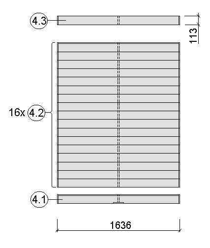
26 Pos Benennung Abmessung (mm ) Stück Art.-Nr. 1.1 Sockelbohle 38/55/634 1 G Wandbohle 38/50/634 1 G Abschlussbohle 38/113/634 1 G Wandbohle 38/121/ G Wandbohle 38/121/523 2 G Wandbohle 38/121/ G Abschlussbohle 38/113/ G Wandbohle 38/121/ G Abschlussbohle 38/113/806 1 G Wandbohle 38/121/ G Abschlussbohle 38/113/ G Sockelbohle 38/121/ G Wandbohle 38/121/ G Abschlussbohle 38/113/ G Wandbohle 38/121/ G Wandbohle 38/121/320 1 G

27 Art.-Nr.:

28 Art.-Nr.:
29 Art.-Nr.:

30 29
31 Pos Benennung Abmessung (mm ) Stück Art.-Nr. 1.1 Sockelbohle 38/55/634 1 G Wandbohle 38/50/634 1 G Abschlussbohle 38/113/634 1 G Wandbohle 38/121/ G Wandbohle 38/121/523 2 G Wandbohle 38/121/ G Abschlussbohle 38/113/ G Wandbohle 38/121/ G Abschlussbohle 38/113/ G Sockelbohle 38/121/ G Wandbohle 38/121/ G Abschlussbohle 38/113/ G Sockelbohle 38/121/ G Wandbohle 38/121/ G Abschlussbohle 38/113/ G Wandbohle 38/121/ G Wandbohle 38/121/320 1 G

32 Art.-Nr.:

33 Art.-Nr.:


34 Art.-Nr.:

35 34

36 Pos Benennung Abmessung (mm ) Stück Art.-Nr. 1.1 Sockelbohle 38/55/634 1 G Wandbohle 38/50/634 1 G Abschlussbohle 38/113/634 1 G Wandbohle 38/121/ G Wandbohle 38/121/523 2 G Wandbohle 38/121/ G Abschlussbohle 38/113/ G Wandbohle 38/121/ G Abschlussbohle 38/113/ G Sockelbohle 38/121/ G Wandbohle 38/121/ G Abschlussbohle 38/113/ G Sockelbohle 38/121/ G Wandbohle 38/121/ G Abschlussbohle 38/113/ G Wandbohle 38/121/ G Wandbohle 38/121/320 1 G


37 Abb.: Art.-Nr


38 Abb.: Art.-Nr


39 Abb.: Art.-Nr

40 Abb.: Art.-Nr


41 Abb.: Art.-Nr


42 Schnitt B-B Schnitt A-A 41


43 Art.-Nr.: Art.-Nr.: Art.-Nr.: HT 42


44 Art.-Nr.: Art.-Nr.: Art.-Nr.: GTK 43


45 A-A Abb.: Art.-Nr


46 45


47 46


48 47 Copyright weka-holzbau GmbH, Neubrandenburg

49 48


50 Art.-Nr.: Art.-Nr.: Art.-Nr.:


51 HT Art.-Nr.: Art.-Nr.: Art.-Nr.: A-1. A-2. A-3. 50


52 GTK Art.-Nr.: Art.-Nr.: Art.-Nr.: A-1 A-2 51


53 52
54 53
55 54

56 weka Holzbau GmbH Johannesstr. 16 D Neubrandenburg Tel.: Fax: MA Art.-Nr.: T
MONTAGE-, GEBRAUCHS- UND WARTUNGSANLEITUNG
 MONTAGE-, GEBRAUCHS- UND WARTUNGSANLEITUNG GB FR IT ASSEMBLY, USER AND MAINTENANCE INSTRUCTIONS SWIMMING POOL NOTICE DE MONTAGE, D'UTILISATION ET D'ENTRETIEN PISCINE ISTRUZIONI DI MONTAGGIO, USO E MANUTENZIONE
Schwimmbad Bausatz Toprail
 Montage-, Bedienungs- und Wartungsanleitung en fr it ASSEMBLY, USER AND MAINTENANCE INSTRUCTIONS NOTICE DE MONTAGE, D'UTILISATION ET D'ENTRETIEN ISTRUZIONI DI MONTAGGIO, USO E MANUTENZIONE Schwimmbad Bausatz
Hochbeet. Art.-Nr.: Art.-Nr.: Art.-Nr.: Art.-Nr.: Art.-Nr.:
 www.wekaholzbau.com Hochbeet Art.Nr.: 66.08.200 Art.Nr.: 66.2008.000 Art.Nr.: 66.2008.300 Art.Nr.: 66.2008.500 Art.Nr.: 66.2008.600 Montage, Bedienungs und Wartungsanleitung T2 de Jetzt scannen und noch
Montage-, Bedienungs- und Wartungsanleitung
 Montage-, Bedienungs- und Wartungsanleitung en fr it ASSEMBLY, USER AND MAINTENANCE INSTRUCTIONS NOTICE DE MONTAGE, D'UTILISATION ET D'ENTRETIEN ISTRUZIONI DI MONTAGGIO, USO E MANUTENZIONE Rasenmähergarage
Montage-, Gebrauchs- und Wartungsanleitung
 Kinderschaukel Art.-Nr. 816.2101.00.00 Art.-Nr. 816.2103.00.01 Montage-, Gebrauchs- und Wartungsanleitung de T2-20.39 Stand: 1604 - de - Sehr geehrte Kundin, sehr geehrter Kunde, danke, dass Sie sich für
Hochbeet. Montage-, Bedienungs- und Wartungsanleitung
 Montage-, Bedienungs- und Wartungsanleitung Hochbeet Art.-Nr.: 669.1208.20400 / 21400 Art.-Nr.: 669.1208.13400 / 15400 / 16400 Art.-Nr.: 669.2008.40000 / 43000 / 45000 / 46000 Stand: 1810 - de - Sehr geehrte
Montage-, Bedienungs- und Wartungsanleitung
 Montage-, Bedienungs- und Wartungsanleitung en fr it ASSEMBLY, USER AND MAINTENANCE INSTRUCTIONS NOTICE DE MONTAGE, D'UTILISATION ET D'ENTRETIEN ISTRUZIONI DI MONTAGGIO, USO E MANUTENZIONE Art.-Nr.: 537.2015.30/
Montage-, Bedienungs- und Wartungsanleitung
 Montage-, Bedienungs- und Wartungsanleitung en fr it ASSEMBLY, USER AND MAINTENANCE INSTRUCTIONS NOTICE DE MONTAGE, D'UTILISATION ET D'ENTRETIEN ISTRUZIONI DI MONTAGGIO, USO E MANUTENZIONE Art.-Nr.: 500.0136.00.00
Montage-, Bedienungs- und Wartungsanleitung
 Montage-, Bedienungs- und Wartungsanleitung en fr it ASSEMBLY, USER AND MAINTENANCE INSTRUCTIONS NOTICE DE MONTAGE, D'UTILISATION ET D'ENTRETIEN ISTRUZIONI DI MONTAGGIO, USO E MANUTENZIONE Art.-Nr.: 539.2015.30
Montage-, Bedienungs- und Wartungsanleitung
 Montage-, Bedienungs- und Wartungsanleitung en fr it ASSEMBLY, USER AND MAINTENANCE INSTRUCTIONS NOTICE DE MONTAGE, D'UTILISATION ET D'ENTRETIEN ISTRUZIONI DI MONTAGGIO, USO E MANUTENZIONE Art.-Nr.: 537.1515.30.00
UP Unterputz-Montage Montage en encastré Recessed mounting
 Wandeinbau UP Unterputz-Montage Montage en encastré Recessed mounting PAL/LED IP4 Arbeiten an den elektrischen Anlagen dürfen nur von autorisierten Fachleuten nach den örtlichen Vorschriften ausgeführt
Montage-, Bedienungs- und Wartungsanleitung
 Montage-, Bedienungs- und Wartungsanleitung en fr it ASSEMBLY, USER AND MAINTENANCE INSTRUCTIONS NOTICE DE MONTAGE, D'UTILISATION ET D'ENTRETIEN ISTRUZIONI DI MONTAGGIO, USO E MANUTENZIONE Art.-Nr.: 536.2020.42
Montage-, Bedienungs- und Wartungsanleitung
 Montage-, Bedienungs- und Wartungsanleitung en fr it ASSEMBLY, USER AND MAINTENANCE INSTRUCTIONS NOTICE DE MONTAGE, D'UTILISATION ET D'ENTRETIEN ISTRUZIONI DI MONTAGGIO, USO E MANUTENZIONE Art.-Nr.: 530.2015.30
2 IP X4 WLS/FL IP24. Montage-Anleitung Instructions de montage Assembling instructions. 225 cm. 60 cm 0
 WLS/FL IP Arbeiten an den elektrischen Anlagen dürfen nur von autorisierten Fachleuten nach den örtlichen Vorschriften ausgeführt werden. Für nicht fachgerechte Installation wird jegliche Haftung abgelehnt.
08/12. Gebrauchsanleitung Trekkingrucksäcke Trekking rucksacks Instructions for use Notice d'emploi pour sacs à dos de trek
 08/12 Gebrauchsanleitung Trekkingrucksäcke Trekking rucksacks Instructions for use Notice d'emploi pour sacs à dos de trek X-TRANSITION Bedingungen der JACK WOLFSKIN 3-Jahres-Gewährleistung Terms and
AP Aufputz-Montage Montage en applique Surface mounting
 PAL/LED IP44, CH IP4 AP Aufputz-Montage Montage en applique Surface mounting Arbeiten an den elektrischen Anlagen dürfen nur von autorisierten Fachleuten nach den örtlichen Vorschriften ausgeführt werden.
1 225 cm IP X4 SLI/FL IP24. Montage-Anleitung Instructions de montage Assembling instructions. 60 cm 0
 Sensor-Schalter aussen unten links und rechts SLI/FL IP Interrupteurs sensitifs en bas à l'extérieur à gauche et à droite Sensor switches outside left and right below Arbeiten an den elektrischen Anlagen
IP X4 MOA/SL/FL IP44, CH IP24. Montage-Anleitung Instructions de montage Assembling instructions. 225 cm. 60 cm 0
 MOA/SL/FL IP44, CH IP4 Arbeiten an den elektrischen Anlagen dürfen nur von autorisierten Fachleuten nach den örtlichen Vorschriften ausgeführt werden. Für nicht fachgerechte Installation wird jegliche
2 IP X4 TAI/LED IP44, CH IP24. Montage-Anleitung Instructions de montage Assembling instructions. 225 cm. 60 cm 0
 Montage-Anleitung Instructions de montage Assembling instructions TAI/LED IP, CH IP Sensor-Schalter aussen unten rechts Interrupteur sensitif en bas à l'extérieur à droite Sensor switch outside right below
Montageanleitung Installation Instructions Notice de Montage
 Montageanleitung Installation Instructions Notice de Montage R Reflexlichtschranke / Reflexlichttaster Retro-reflective sensor / Diffuse reflection sensor Système réflex / Système réflexion directe OE
MONTAGE-, BEDIENUNGS- UND WARTUNGSANLEITUNG. Gartenlaube
 MONTAGE-, BEDIENUNGS- UND WARTUNGSANLEITUNG Gartenlaube de T2-20.29 Gr. 1 Art.-Nr. 651.2929.00... Gr. 2 Art.-Nr. 651.3333.00... Gr. 3 Art.-Nr. 651.3838.00... Gr. 4 Art.-Nr. 651.4343.00... Stand 1631 Sehr
Montageanleitung Installation Manual
 Montageanleitung Installation Manual Inventux X-Series Flachdach Flat Roof 2 Oelschläger Metalltechnik GmbH Hertzstr. 1-3 D-27318 Hoya Telefon: +49 (0) 4251 816 0 Telefax: +49 (0) 4251 816 81 Email: solar@oelschlaeger.de
Weka Garten [Q] Storage
![Weka Garten [Q] Storage](/thumbs/92/107862825.jpg "Weka Garten [Q] Storage") Montage-, Bedienungs- und Wartungsanleitung en fr it ASSEMBLY, USER AND MAINTENANCE INSTRUCTIONS NOTICE DE MONTAGE, D'UTILISATION ET D'ENTRETIEN ISTRUZIONI DI MONTAGGIO, USO E MANUTENZIONE Weka Garten
Montage-, Bedienungs- und Wartungsanleitung en fr it ASSEMBLY, USER AND MAINTENANCE INSTRUCTIONS NOTICE DE MONTAGE, D'UTILISATION ET D'ENTRETIEN ISTRUZIONI DI MONTAGGIO, USO E MANUTENZIONE Weka Garten
Montage-, Bedienungs- und Wartungsanleitung
 Montage-, Bedienungs- und Wartungsanleitung en fr it ASSEMBLY, USER AND MAINTENANCE INSTRUCTIONS NOTICE DE MONTAGE, D'UTILISATION ET D'ENTRETIEN ISTRUZIONI DI MONTAGGIO, USO E MANUTENZIONE Hochbeet Art.-Nr.:
Snap-in switch for switches PSE, MSM and MCS 30
 Product manual Snap-in switch for switches PSE, MSM and MCS 30 CONTENTS 1. PRODUCT DESCRIPTION 2. DATA AND DIMENSIONAL DRAWINGS 2.1. Technical Data 2.2. Dimensions of PSE with a Mounting Diameter 19 mm
Weka Garten [Q] Multi
![Weka Garten [Q] Multi](/thumbs/55/36396994.jpg "Weka Garten [Q] Multi") Montage-, Bedienungs- und Wartungsanleitung en fr it ASSEMBLY, USER AND MAINTENANCE INSTRUCTIONS NOTICE DE MONTAGE, D'UTILISATION ET D'ENTRETIEN ISTRUZIONI DI MONTAGGIO, USO E MANUTENZIONE Weka Garten
Montage-, Bedienungs- und Wartungsanleitung en fr it ASSEMBLY, USER AND MAINTENANCE INSTRUCTIONS NOTICE DE MONTAGE, D'UTILISATION ET D'ENTRETIEN ISTRUZIONI DI MONTAGGIO, USO E MANUTENZIONE Weka Garten
Weka Garten [Q] Multi
![Weka Garten [Q] Multi](/thumbs/58/41928673.jpg "Weka Garten [Q] Multi") Montage-, Bedienungs- und Wartungsanleitung en fr it ASSEMBLY, USER AND MAINTENANCE INSTRUCTIONS NOTICE DE MONTAGE, D'UTILISATION ET D'ENTRETIEN ISTRUZIONI DI MONTAGGIO, USO E MANUTENZIONE Weka Garten
Montage-, Bedienungs- und Wartungsanleitung en fr it ASSEMBLY, USER AND MAINTENANCE INSTRUCTIONS NOTICE DE MONTAGE, D'UTILISATION ET D'ENTRETIEN ISTRUZIONI DI MONTAGGIO, USO E MANUTENZIONE Weka Garten
Weka Garten[Q] Kompakt
![Weka Garten[Q] Kompakt](/thumbs/55/36397009.jpg "Weka Garten[Q] Kompakt") Montage-, Bedienungs- und Wartungsanleitung en fr it ASSEMBLY, USER AND MAINTENANCE INSTRUCTIONS NOTICE DE MONTAGE, D'UTILISATION ET D'ENTRETIEN ISTRUZIONI DI MONTAGGIO, USO E MANUTENZIONE Weka Garten[Q]
Montage-, Bedienungs- und Wartungsanleitung en fr it ASSEMBLY, USER AND MAINTENANCE INSTRUCTIONS NOTICE DE MONTAGE, D'UTILISATION ET D'ENTRETIEN ISTRUZIONI DI MONTAGGIO, USO E MANUTENZIONE Weka Garten[Q]
Weka Garten[Q] Teras
![Weka Garten[Q] Teras](/thumbs/58/41925811.jpg "Weka Garten[Q] Teras") Montage-, Bedienungs- und Wartungsanleitung en fr it ASSEMBLY, USER AND MAINTENANCE INSTRUCTIONS NOTICE DE MONTAGE, D'UTILISATION ET D'ENTRETIEN ISTRUZIONI DI MONTAGGIO, USO E MANUTENZIONE Weka Garten[Q]
Montage-, Bedienungs- und Wartungsanleitung en fr it ASSEMBLY, USER AND MAINTENANCE INSTRUCTIONS NOTICE DE MONTAGE, D'UTILISATION ET D'ENTRETIEN ISTRUZIONI DI MONTAGGIO, USO E MANUTENZIONE Weka Garten[Q]
Montage-, Bedienungs- und Wartungsanleitung
 Montage-, Bedienungs- und Wartungsanleitung en fr it ASSEMBLY, USER AND MAINTENANCE INSTRUCTIONS NOTICE DE MONTAGE, D'UTILISATION ET D'ENTRETIEN ISTRUZIONI DI MONTAGGIO, USO E MANUTENZIONE Ergänzungsbausatz
Montage-, Bedienungs- und Wartungsanleitung
 Montage-, Bedienungs- und Wartungsanleitung en fr it ASSEMBLY, USER AND MAINTENANCE INSTRUCTIONS NOTICE DE MONTAGE, D'UTILISATION ET D'ENTRETIEN ISTRUZIONI DI MONTAGGIO, USO E MANUTENZIONE Art.-Nr.: 508.2018.00
Großbaukasten Turmdrehkran
 Großbaukasten Turmdrehkran 10891 Modell: Märklin Metallbaukasten Turmdrehkran mit ca. 1.050 Teilen. Einmalige Sonderauflage des Wahrzeichens der Metallbaukastenserie der ersten Hälfte des 20. Jahrhunderts.
Montage-, Bedienungs- und Wartungsanleitung
 Montage-, Bedienungs- und Wartungsanleitung en fr it ASSEMBLY, USER AND MAINTENANCE INSTRUCTIONS NOTICE DE MONTAGE, D'UTILISATION ET D'ENTRETIEN ISTRUZIONI DI MONTAGGIO, USO E MANUTENZIONE Art.-Nr.: 506.2018.00
Hama GmbH & Co KG D Monheim/Germany
 Hama GmbH & Co KG D-86651 Monheim/Germany www.hama.com All listed brands are trademarks of the corresponding companies. Errors and omissions excepted, and subject to technical changes. Our general terms
Montage-, Bedienungs- und Wartungsanleitung
 Montage-, Bedienungs- und Wartungsanleitung en fr it ASSEMBLY, USER AND MAINTENANCE INSTRUCTIONS NOTICE DE MONTAGE, D'UTILISATION ET D'ENTRETIEN ISTRUZIONI DI MONTAGGIO, USO E MANUTENZIONE Art.-Nr.: 514.2020.40
Attention! Allgemeine Hinweise zur Montage
 DE MONTAGEANLEITUNG EN ASSEMBLY MANUAL Holzlattenrost 0 cm Horizontal Wood slatted (0 cm Horizontal) bed base 0 cm Vertikal (0 cm Vertikal) SMATBett STANDAT SYSTEM DE ur die Montage benotigen Sie folgendes:
ATEX-Check list. Compiled by: Date: Signature: Acceptable practice at the determination of flash point: Closed cup according to ISO 2719
 Fire and explosion hazard ATEX 137 1999/92/EG und ATEX 95 2014/34/EU Danger assessment and determination of explosion protection zone for the test space as well as the installation site ATEX-Check list
TV - Unterteil Montageanleitung Notice de montage Assembly instruction
 Montageanleitung Notice de montage Assembly instruction the furniture factory R TV - Unterteil 1503 Bitte die Sicherheitshinweise auf der letzten Seite beachten! Please note: saftey instructions on the
Schreibtisch Montageanleitung Notice de montage Assembly instruction
 Montageanleitung Notice de montage Assembly instruction the furniture factory R Schreibtisch 4036 Ø 5 + 8 mm Bitte die Sicherheitshinweise auf der letzten Seite beachten Please note: saftey instructions
Outdoor-Tasche. Operating Instructions Bedienungsanleitung GB D
 00 181243 Outdoor Case Outdoor-Tasche Splish Splash Operating Instructions Bedienungsanleitung GB D A B C D OPEN G Operating instruction 1. Important Notes Children are not permitted to play with the device.
TAVOLI DA LAVORO SU GAMBE WORK TABLES TABLES DE TRAVAIL CABINETS ARBEITSTISCHE
 IT I nuovi tavoli su gambe sono costruiti con un rivoluzionario sistema che permette di assemblare il prodotto in pochi secondi, consentendo rapidità di montaggio e al contempo permettendo di ridurre i
 Verwenden Sie nur Original-KRONE-Ersatzteile! Das gibt Sicherheit und spart Kosten! Use Original-KRONE parts only This will increase operational reliability and help to save costs! N'utiliser que des piéces
 Verwenden Sie nur Original-KRONE-Ersatzteile! Das gibt Sicherheit und spart Kosten! Use Original-KRONE parts only This will increase operational reliability and help to save costs! N'utiliser que des piéces
 Verwenden Sie nur Original-KRONE-Ersatzteile! Das gibt Sicherheit und spart Kosten! Use Original-KRONE parts only This will increase operational reliability and help to save costs! N'utiliser que des piéces
150-in-1. Handbuch / Manual / Manuel. Externer Card Reader USB 2.0
 Handbuch / Manual / Manuel Vielen Dank, dass Sie sich für ein Produkt von ultron entschieden haben. Wir wünschen Ihnen viel Freude mit Ihrem neuen Gerät! CE-Erklärung und Hinweise Hiermit erklärt die
Hohlwanddose HWD 90. Montageanleitung / Assembly instructions / Instructions de montage / Montage instructies
 Hohlwanddose HWD 90 HWD 90 cavity wall box / Boîtier pour parois creuses HWD 90 / Inbouwdoos voor holle wanden HWD 90 DIBt-Zulassung * Für Bauteile der Feuerwiderstandsklasse F90 nach DIN 40- Montageanleitung
Where are we now? The administration building M 3. Voransicht
 Let me show you around 9 von 26 Where are we now? The administration building M 3 12 von 26 Let me show you around Presenting your company 2 I M 5 Prepositions of place and movement There are many prepositions
Montage-, Bedienungs- und Wartungsanleitung
 Montage-, Bedienungs- und Wartungsanleitung Art.-Nr.: 219.2424.70041 Art.-Nr.: 219.3024.70041 Art.-Nr.: 219.3030.70041 Stand: 1703 - de - Vorwort Allgemeines Sehr geehrte Kundin, sehr geehrter Kunde, danke,
 Verwenden Sie nur Original-KRONE-Ersatzteile! Das gibt Sicherheit und spart Kosten! Use Original-KRONE parts only This will increase operational reliability and help to save costs! N'utiliser que des piéces
 Verwenden Sie nur Original-KRONE-Ersatzteile! Das gibt Sicherheit und spart Kosten! Use Original-KRONE parts only This will increase operational reliability and help to save costs! N'utiliser que des piéces
 Verwenden Sie nur Original-KRONE-Ersatzteile! Das gibt Sicherheit und spart Kosten! Use Original-KRONE parts only This will increase operational reliability and help to save costs! N'utiliser que des piéces
 Verwenden Sie nur Original-KRONE-Ersatzteile! Das gibt Sicherheit und spart Kosten! Use Original-KRONE parts only This will increase operational reliability and help to save costs! N'utiliser que des piéces
COMPRESSORI A VITE SCREW COMPRESSORS COMPRESSEURS À VIS SCHRAUBKOMPRESSOREN
 I compressori sono progettati per il funzionamento continuo nelle più severe condizioni di utilizzo. Particolare attenzione per modularità, consumi energetici, bassi costi di manutenzione, facilità di
Entwurf. preliminary
 KAPRi plus Erweiterungsset M12 KAPRi plus Extension Kit M12 KAPRi plus Kit d Extension M12 Bedienungsanleitung / User instructions / Instructions d installation 899366 KAPRi plus Erweiterungsset M12 /
VGM. VGM information. HAMBURG SÜD VGM WEB PORTAL USER GUIDE June 2016
 Overview The Hamburg Süd VGM Web portal is an application that enables you to submit VGM information directly to Hamburg Süd via our e-portal Web page. You can choose to enter VGM information directly,
11 EN 81-70 Page 1 of 2 Standard: INTERPRETATION RELATED TO. Clause(s): 5.4.2.3
: 5.4.2.3") CEN RELATED TO 11 Page 1 of 2 Standard: Edition: 2003 Clause(s): 5.4.2.3 Valid from: 15/09/2010 Date of modification: Key-word(s): Car operating panel, Two entrance lift Replacing interpretation No.: QUESTION
CEN RELATED TO 11 Page 1 of 2 Standard: Edition: 2003 Clause(s): 5.4.2.3 Valid from: 15/09/2010 Date of modification: Key-word(s): Car operating panel, Two entrance lift Replacing interpretation No.: QUESTION
Montageanleitung Instructions de montage Istruzioni per il montaggio Assembly Instructions
 Qualitätsmanagement-System Umweltmanagement-System Montageanleitung Instructions de montage Istruzioni per il montaggio Assembly Instructions Zertifiziertes ISO 900 Zertifiziertes ISO 400 Vertikalauszug
D: MONTAGEANLEITUNG DER SPEICHER-VERKLEIDUNG KERAMIK GB: INSTRUCTION SHEET OF THE THERMAL SAFETY COVER CERAMIC
 D: MONTAGEANLEITUNG DER SPEICHER-VERKLEIDUNG KERAMIK GB: INSTRUCTION SHEET OF THE THERMAL SAFETY COVER CERAMIC F : NOTICE DE MONTAGE DES PROTECTIONS THERMIQUES CÉRAMIQUE Hinweis: Notice: Wir empfehlen
Programmieranleitung CADAS 100 LPG 210
 Programmieranleitung CADAS 100 LPG 210 Küvetten-Test LCK 555 Seite 1 BSB 5 BSB [n] Ausgabe 9804 Achtung! Das Ausgabedatum dieser Programmieranleitung muß mit dem Ausgabedatum der Arbeitsvorschrift der
Bedienungsanleitung SUNNYHEAT Standfuß (Art. Nr )
") Bedienungsanleitung SUNNYHEAT Standfuß (Art. Nr. 221012) Der SUNNYHEAT Standfuß ist zur Positionierung Ihres Heizpaneels auf dem Standfuß gedacht. Anwendung findet der Standfuß bei allen Paneelen außer
Bedienungsanleitung SUNNYHEAT Standfuß (Art. Nr. 221012) Der SUNNYHEAT Standfuß ist zur Positionierung Ihres Heizpaneels auf dem Standfuß gedacht. Anwendung findet der Standfuß bei allen Paneelen außer
Word-CRM-Upload-Button. User manual
 Word-CRM-Upload-Button User manual Word-CRM-Upload for MS CRM 2011 Content 1. Preface... 3 2. Installation... 4 2.1. Requirements... 4 2.1.1. Clients... 4 2.2. Installation guidelines... 5 2.2.1. Client...
BRUUDT Kennzeichenhalter für die Honda NC750X ab 2016 BRUUDT Tail Tidy for the Honda NC750X 2016 and onwards.
 Montageanleitung Mounting instructions BRUUDT Kennzeichenhalter für die Honda NC750X ab 2016 BRUUDT Tail Tidy for the Honda NC750X 2016 and onwards. Noch einmal vielen Dank, dass Sie sich für unsere Produkte
Ersatzteilliste. Spare parts list
 Ersatzteilliste Spare parts list Liste des piéces de rechange Nußbaum Hebetechnik GmbH & Co.KG//Korker Straße 24//D-77694 Kehl-Bodersweier Tel: +49(0)7853/8990 Fax: +49(0)7853/8787 E-mail: nussbaum.lifts@t-online.de//http://www.nussbaum-lifts.de
Programmieranleitung CADAS 100 LPG 158
 Kupfer Programmieranleitung CADAS 100 LPG 158 Küvetten-Test LCK 529 Seite 1 Ausgabe 98/04 Achtung! Das Ausgabedatum dieser Programmieranleitung muß mit dem Ausgabedatum der Arbeitsvorschrift der Reagenzien
UNIVERSAL REGENDUSCHE
 UNIVERSAL REGENDUSCHE D MONTAGEANLEITUNG GB ASSEMBLY INSTRUCTIONS F INSTRUCTIONS DE MONTAGE D WichtigeHinweise! GB IMPORTANT ROCOMMENDATIONS! F RECOMMANDATIONS IMPORTANTES! Halten Sie Kinder vom Verpackungsmaterial
Montage-, Bedienungs- und Wartungsanleitung
 Montage-, Bedienungs- und Wartungsanleitung Infrarot Kabine FSF 2 Art.-Nr.: 548.1310.41 Stand: 1145 Sehr geehrte Kundin, sehr geehrter Kunde, lesen Sie diese Anleitung vor dem Aufbau der Infrarotkabine
Thule Excellence XT Instructions
 Thule Excellence XT Instructions 3DF/8.W35.2013 1801814100 Instructions Security x1 x1 x1 m x3 x1 x2 1 Max 80 mm Min 18 mm Max 30 mm Min 555 mm Max 935 mm Max 80 mm Min 18 mm Max 30 mm Min. 800 mm i Thule
Release Notes BRICKware 7.5.4. Copyright 23. March 2010 Funkwerk Enterprise Communications GmbH Version 1.0
 Release Notes BRICKware 7.5.4 Copyright 23. March 2010 Funkwerk Enterprise Communications GmbH Version 1.0 Purpose This document describes new features, changes, and solved problems of BRICKware 7.5.4.
Montage-, Bedienungs- und Wartungsanleitung
 Montage-, Bedienungs- und Wartungsanleitung en fr it ASSEMBLY, USER AND MAINTENANCE INSTRUCTIONS NOTICE DE MONTAGE, D'UTILISATION ET D'ENTRETIEN ISTRUZIONI DI MONTAGGIO, USO E MANUTENZIONE Art.-Nr.: 218.2421.70041
Clôture Verre / Glas Windschutz H. 100 cm
 Clôture Verre / Glas Windschutz H. 100 cm FR DE Notice de montage et informations à lire et à conserver Gebrauchsanleitung- sorgfältig lesen und aufbewahren Lisez tout le manuel avant l'installation et
VGM. VGM information. HAMBURG SÜD VGM WEB PORTAL - USER GUIDE June 2016
 Overview The Hamburg Süd VGM-Portal is an application which enables to submit VGM information directly to Hamburg Süd via our e-portal web page. You can choose to insert VGM information directly, or download
Test Report. Test of resitance to inertia effects of Zirkona Backwall. Sled Test (Frontal Impact) 20 g / 30 ms
 20 g / 30 ms") Test Report Test of resitance to inertia effects of Zirkona Backwall Sled Test (Frontal Impact) 20 g / 30 ms This report serves solely as a documentation of test results. 93XS0002-00_TdC.doc Page 1 1.
Test Report Test of resitance to inertia effects of Zirkona Backwall Sled Test (Frontal Impact) 20 g / 30 ms This report serves solely as a documentation of test results. 93XS0002-00_TdC.doc Page 1 1.
Information zu den Drucksachen
 Information zu den Drucksachen Ihre persönlichen Einladungen sind uns sehr wichtig. Deshalb übernehmen wir den Versand und die Portokosten. Wir bitten Sie um Verständnis dafür, dass wir diesen Service
Westfalia Bedienungsanleitung. Nr
 Westfalia Bedienungsanleitung Nr. 108610 Bedienungsanleitung Edelstahl Sicherheits-Brennbehälter Artikel Nr. 10 99 83 Sicherheitshinweise Der Sicherheits-Brennbehälter ist zur Verwendung in dem Westfalia
Montageanleitung Assembly Instruction Artikel: Werkstattschrank mit 2 Türen
 1 Montageanleitung Assembly Instruction Artikel: Werkstattschrank mit 2 Türen Allgemeine Hinweise: Prüfen Sie bitte vor Zusammenbau, ob alle Teile vorhanden und unbeschädigt sind. Sollte das nicht der
Programmieranleitung CADAS 100 LPG 210
 Phosphat-Phosphor Programmieranleitung CADAS 100 PG 210 Küvetten-Test Seite 1 CK 350 Ausgabe 91/03 Achtung! Das Ausgabedatum dieser Programmieranleitung muß mit dem Ausgabedatum der Arbeitsvorschrift der
Registration of residence at Citizens Office (Bürgerbüro)
") Registration of residence at Citizens Office (Bürgerbüro) Opening times in the Citizens Office (Bürgerbüro): Monday to Friday 08.30 am 12.30 pm Thursday 14.00 pm 17.00 pm or by appointment via the Citizens
Registration of residence at Citizens Office (Bürgerbüro) Opening times in the Citizens Office (Bürgerbüro): Monday to Friday 08.30 am 12.30 pm Thursday 14.00 pm 17.00 pm or by appointment via the Citizens
DENTAL IMPLANTS BY CAMLOG medical
 IMPLANT PASS DENTAL IMPLANTS BY CAMLOG medical devices made in germany for your well-being and a natural appearance. Personal data Surname First name Address ZIP code City Date of birth Health insurance
11 kw** E82MV222_4B kw**
 EDK82ZWKN4 00459189 10/02 Netzschleifklemme Typ E82ZWKN4 Diese Anleitung enthält wichtige Hinweise für den Einsatz der Netzschleifklemme E82ZWKN4 und beschreibt deren Montage. ist nur gültig - für Netzschleifklemmen
Lukas Hydraulik GmbH Weinstraße 39 D Erlangen. Mr. Sauerbier. Lukas Hydraulik GmbH Weinstraße 39 D Erlangen
 Technical Report No. 028-71 30 95685-350 of 22.02.2017 Client: Lukas Hydraulik GmbH Weinstraße 39 D-91058 Erlangen Mr. Sauerbier Manufacturing location: Lukas Hydraulik GmbH Weinstraße 39 D-91058 Erlangen
WM4L. Höhenverstellbarer Stand. MAX 10kg / (22lbs) jede Ablage MONTAGEANLEITUNG. v.17.11
 jede Ablage MONTAGEANLEITUNG. v.17.11") Höhenverstellbarer Stand MONTAGEANLEITUNG v.17.11 ACHTUNG: NIEMALS DAS MAXIMAL ZULÄSSIGE BELASTUNGSGEWICHT ÜBERSCHREITEN. MISSACHTUNG KANN ZU SACHSCHÄDEN ODER SCHWEREN VERLETZUNGEN FÜHREN! WM4L MAX 10kg
Höhenverstellbarer Stand MONTAGEANLEITUNG v.17.11 ACHTUNG: NIEMALS DAS MAXIMAL ZULÄSSIGE BELASTUNGSGEWICHT ÜBERSCHREITEN. MISSACHTUNG KANN ZU SACHSCHÄDEN ODER SCHWEREN VERLETZUNGEN FÜHREN! WM4L MAX 10kg
hanit Assembly Instruction - Sandbox System Thar -
 Thank you for purchasing a hanit recycling plastic product, We wish you a lot of pleasure with that product. Please find below important installation instructions which need to be taken into consideration
PONS DIE DREI??? FRAGEZEICHEN, ARCTIC ADVENTURE: ENGLISCH LERNEN MIT JUSTUS, PETER UND BOB
 Read Online and Download Ebook PONS DIE DREI??? FRAGEZEICHEN, ARCTIC ADVENTURE: ENGLISCH LERNEN MIT JUSTUS, PETER UND BOB DOWNLOAD EBOOK : PONS DIE DREI??? FRAGEZEICHEN, ARCTIC ADVENTURE: Click link bellow
NOTICE DE MONTAGE NOTE OF ASSEMBLY / INSTRUCCIONES DE MONTAJE / MANTAGE ANLEITUNG BV8703K92MX-MO POLLY COIFFEUSE. 82cm.
 NOTICE DE MONTAGE NOTE OF ASSEMBLY / INSTRUCCIONES DE MONTAJE / MANTAGE ANLEITUNG -0-0 REFERENCE NO. REFERENCE NO. REFERENCIA NO. REFERENZ NR. BV03KMX-MO NOM DU PRODUIT PRODUCT NAME NOMBRE DEL PRODUCTO
Werkzeughalter Porte-outil / Tool holder
 Werkzeuge für die Rückseitenbearbeitung System HAT Höhenverstellbar Outils pour tronçonnage réglables en hauteur Tools for rear processing System high adjustable tool-holders Im werden Werkzeuge für die
Spielmatte Schach Jeu d échecs
 NC-1167 DEUTSCH FRANÇAIS Spielmatte Schach Jeu d échecs für 2 Spieler 2 joueurs Sehr geehrte Kunden, wir danken Ihnen für den Kauf dieser Spielmatte. Entdecken Sie Spielspaß in XXL diese Spielmatte ist
Fitting Instructions for DG0017 BK Downpipe Grille BMW F800GT 2013
 Fitting Instructions for DG0017 BK Downpipe Grille BMW F800GT 2013 In This Kit There Should Be 1 x Downpipe Grille (DG0017) 2 x M5 Nyloc nuts PICTURE 1 PICTURE 2 PICTURE 3 PICTURE 4 1 PICTURE 5 PICTURE
L Montageanleitung Assembly instructions Instruction de montage EASYHOMESYSTEM TH-EHS. Änderungen vorbehalten Alle Rechte vorbehalten
 L-09-1-50 Montageanleitung Assembly instructions Instruction de montage EASYHOMESYSTEM TH-EHS Änderungen vorbehalten Alle Rechte vorbehalten Komponenten / Components / Composants / Componenti PGD Touch
Programmieranleitung CADAS 100 LPG 158
 Wasserhärte Programmieranleitung CADAS 100 LPG 158 Küvetten-Test LCK 327 Seite 1 Ausgabe 97/06 Achtung! Das Ausgabedatum dieser Programmieranleitung muß mit dem Ausgabedatum der Arbeitsvorschrift der Reagenzien
PORTA 40 EKU-PORTA 40 H
 PORTA EKU-PORTA 40 40 PORTA 40 Design-Beschlag mit schlanken Laufschienen Unsichtbare Technik Designer fitting with slim running tracks Invisible running system Ferrure design avec rails de roulement étroits
Electrical tests on Bosch unit injectors
 Valid for Bosch unit injectors with order numbers 0 414 700 / 0 414 701 / 0 414 702 Parts Kit Magnet*: - F00H.N37.925 - F00H.N37.933 - F00H.N37.934 * For allocation to the 10-place Bosch order number,
Programmieranleitung CADAS 100 LPG 158
 Programmieranleitung CADAS 100 LPG 158 Ammonium-Stickstoff Küvetten-Test LCK 304 Seite 1 Ausgabe 98/04 Achtung! Das Ausgabedatum dieser Programmieranleitung muß mit dem Ausgabedatum der Arbeitsvorschrift
Ladeluftkühler / Intercooler Honda Civic Type R Kit-Nr.:
 190001056 - Einbauanleitung / Installation Instruction - Ladeluftkühler / Intercooler Honda Civic Type R Kit-Nr.: 200001086 Wichtige Hinweise! Diese Montageanleitung ist unbedingt vor Beginn der Einbauarbeiten
Montageanleitung DORMA PT 41. Winkeloberlichtbeschlag mit beidseitiger Aussteifung. Installation instruction DORMA PT 41
 Montageanleitung DORMA PT 41 Winkeloberlichtbeschlag mit beidseitiger Aussteifung Installation instruction DORMA PT 41 Patch fitting for overpanel and sidelight with fin fitting on both sides Stand/Issue
Pasta Dryer
 Pasta Dryer 10011459 10011482 Sehr geehrter Kunde, wir gratulieren Ihnen zum Erwerb Ihres Gerätes. Lesen Sie die folgenden Hinweise sorgfältig durch und befolgen Sie diese, um möglichen Schäden vorzubeugen.
design guide vintage StYLe
 design guide 02 vintage StYLe design guide 02 vintage StYLe de die Sehnsucht nach alten Werten en the longing for old values is growing, fr La nostalgie des valeurs anciennes wächst und wir folgen wieder
Montage-, Bedienungs- und Wartungsanleitung
 Montage-, Bedienungs- und Wartungsanleitung en fr it ASSEMBLY, USER AND MAINTENANCE INSTRUCTIONS NOTICE DE MONTAGE, D'UTILISATION ET D'ENTRETIEN ISTRUZIONI DI MONTAGGIO, USO E MANUTENZIONE Art.-Nr.: 351.0809.30450
Technische Daten / Caractéristiques techniques Elektrische Anlage / Schéma électrique Ersatzteilzeichnung / Vue éclatée
 TECHNISCHE DATEN DONNEES TECHNIQUES Index Seite / Page 1 Seite / Page 2 Seite / Page 3 Seite / Page 4-5 Index Technische Daten / Caractéristiques techniques Elektrische Anlage / Schéma électrique Ersatzteilzeichnung
Lukas Hydraulik GmbH Weinstraße 39 D Erlangen. Mr. Sauerbier. Lukas Hydraulik GmbH Weinstraße 39 D Erlangen. edraulic rescue equipment
 Technical Report No. 028-7130 95685-050 of 22.02.2017 Client: Lukas Hydraulik GmbH Weinstraße 39 D-91058 Erlangen Mr. Sauerbier Manufacturing location: Lukas Hydraulik GmbH Weinstraße 39 D-91058 Erlangen