emotion M Anschlussanleitung emotion M Installation Manual
|
|
|
- Axel Kalb
- vor 5 Jahren
- Abrufe
Transkript

1 emotion M Anschlussanleitung emotion M Installation Manual
2 Einleitende Information Sehr geehrte Kunden, wir empfehlen beide Anleitungen und vor allem auch die Warnhinweise vor der Inbetriebnahme gründlich zu lesen und diese zu Beachten. In diesem Handbuch soll der Anschluss des emotion M Lokdekoders erläutert werden. Introduction Dear customer, we highly recommend to read both product manuals and especially the warning notes thoroughly before operation. This manual describes the installation of the emotion M decoder. HINWEIS: Funktionsausgänge Die Spannung der Licht- und Funktionsausgänge ist im Auslieferungszustand auf volle Gleisspannung eingestellt! Vergewissern Sie sich VOR dem Anschluss der Lampen und Funktionsausgänge das die Spannung entsprechend der CV-Liste richtig eingestellt ist! Für Schäden durch Nichtbeachtung dieses Hinweises übernehmen wir keine Haftung. Note concerning the function outputs: The function outputs are set per default to full track voltage! Make sure the CVs of the function outputs are set to the appropriate value before hooking up any lights or other accessories. Massoth cannot be responsible for any damage if this is disregarded. 2
3 Inhaltsverzeichnis Grundlegende Information... Funktionsumfang... Lieferumfang... Inbetriebnahme... Motor- und Gleisanschluss... Einbau... Erweiterte Einstellungen... Anschlüsse auf der Oberseite... Anschlüsse auf der Unterseite... Licht- und Funktionsausgänge... Einbau in Loks ohne Schnittstelle... Anschluss SUSI/Massoth Bus... Technische Daten... Garantie, Reparatur, Kundendienst.. Hotline... Table of Contents General Information... Summary of Functions... Scope of Supply... Hook-Up... Motor and track connection... Installation... Advanced settings... Terminals on the upper side... Terminals on the lower side... Light- and function outputs... Installation without interface... Using the SUSI/Massoth bus... Technical Data... Warranty, Service, Support... Hotline
4 1. Grundlegende Informationen Wir empfehlen beide Anleitungen gründlich zu lesen, bevor Sie den neuen Dekoder in Betrieb nehmen. Einige Funktionen sind nur mit der aktuellsten Firmware nutzbar, führen Sie bei Bedarf ein Update durch Funktionsumfang 14,28 und 128 Fahrstufen 256 interne Fahrstufen Lokadressen programmierbare Fahrkurve Anfahr-, Mittel- und Höchstgeschwindigkeit (sowie Verzögerungszeiten) einstellbar Serielle und parallele Steuerung für alle Licht- und Funktionsausgänge incl. LGB P-Soundupdates Digital- und Analogbetrieb mit automatischer Erkennung Kompatibel zu NMRA DCC und LGB MZS (alle Generationen) Lastregelung neuester Generation (für Digital- und Analogbetrieb) Einstellbare Motorfrequenz (70Hz - 16kHz) 2 Lichtanschlüsse (vorne, hinten) max. je 0,3 A 5 Funktionsausgänge (alle mit konfigurierbaren Sonderfunktionen) 2 x 0,3A (A1+2), 2 x 0,05A (A5+6) und 1 x 0,01A (5V) (A3) 1. General Information We recommend to read this manual carefully before the decoder is installed and operated. Some functions require the latest firmware for availability. Please update the decoder with the latest firmware Summary of Functions 14,28 and 128 speed steps 256 internal speed steps addresses Programmable driving characteristics Adjustable starting speed, medium speed and maximum speed (with acceleration/deceleration time) Serial and parallel control of all light and function outputs, incl. LGB P-Sound updates Digital and analog operation with automatic recognition Compatible with NMRA DCC and LGB MTS (all generations) Latest technology of load control (digital and analog) Adjustable motor frequency (70Hz - 16kHz) 2 light outputs (front, rear) max. 0,3 Amps each 5 function outputs (each programmable with special functions) 2 x 0,3A (A1+2), 2 x 0,05A (A5+6) and 1 x 0,01A (5V) (A3) 4
5 Licht- und Funktionsausgänge dimmbar und analog aktivierbar Programmierbare Blinklicht-, Impuls- und Taktgeberfunktion Rangiergang (mit freier Funktionszuordnung) einfache Funktionszuordnung für alle Funktionsausgänge alle Funktionsausgänge frei adressierbar (F1 - F16) Gesamtbelastbarkeit 1,8 Ampere (Motorendstufe und Funktionsausgänge) Motorendstufe mit 1,2 Ampere belastbar Spannungspufferanschluss für unterbrechungsfreien Lauf integriert Überlast- und Temperaturschutz für Motor- und Funktionsausgänge Resetfunktion für alle CV-Werte Firmware updatefähig 1.2 Lieferumfang emotion M Dekoder mit Getriebeanschlusskabel Klebepad Anschlussanleitung Konfigurationsanleitung Light and function outputs may be dimmed and activated in analog mode Programmable blinking light, shorttime function, and pulse generator function Switching speed (with free function mapping) Easy to use function mapping Free command allocation of all function outputs (F1 - F16) Maximum total load 1,8 Amps (motor and function output) 1,2 Amps motor power amplifier Connector for power buffer (accessory) for smooth running integrated Overload and temperature protection for motor and function outputs Reset function for all CV values Firmware easy to be updated 1.2 Scope of Supply emotion M Decoder with motorblock connecting cable Double-sided tape Connection manual Configuration manual 5
 kurzgeschlossen, kann diese Sicherung nicht wirken und der Dekoder wird zerstört. 2.")
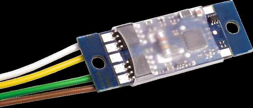
6 2. Inbetriebnahme Bauen Sie den Dekoder sorgfältig nach den Anschlussplänen in dieser Bedienungsanleitung in die Lok ein. Der Dekoder ist generell gegen Kurzschlüsse oder Überlastung gesichert. Werden jedoch beim Einbau Kabel vertauscht oder Kabel verschiedener Funktionen (z.b. Gleis + Motor) kurzgeschlossen, kann diese Sicherung nicht wirken und der Dekoder wird zerstört. 2.1 Motor- und Gleisanschluss Verbinden Sie das weiße (Gleis +) und braune (Gleis -) Kabel mit dem Gleisanschluss des Getriebes. Verbinden Sie das gelbe (Motor +) und grüne (Motor -) Kabel mit dem Motor im Getriebe. 2. Hook-Up Install your decoder in compliance with the connecting diagram in this manual. The decoder is protected against shorts and excessive loads. However, in case of a connection error e.g. a short between a light and the motor, this safety feature cannot work and the decoder will be destroyed subsequently. 2.1 Motor and track connection Connect the white (+) and the brown (-) wire to the track power leads of the motor block. Connect the yellow (+) and the green (-) wire to the motor leads of the motor block. Abbildung 1: Anschluss an Motor + Gleis Illustration 1: Connection diagram track / motor 6

7 2.2 Einbau Sie können den Dekoder mit dem beiliegenden Klebepad befestigen. Alternativ können Sie den Dekoder über die beiden Löcher festschrauben. Achten Sie beim Befestigen darauf, das kein Kurzschluss zu anderen Teilen entsteht. Zusätzliche Kabel für weitere Funktionen nur mit einem kleinen Lötkolben anlöten um Kurzschlüsse zu Bauteilen oder benachbarten Anschlüssen zu vermeiden. Vertauschen Sie keine Anschlusskabel, das kann zur Zerstörung führen! Die Ränder können bei Bedarf abgebrochen werden. 3. Erweiterte Einstellungen Hier finden Sie alle zusätzlichen Funktionen des Dekoders. 3.1 Anschlüsse auf der Oberseite 2.2 Installation You may mount the decoder with either the supplied double-sided tape or with two screws using the mounting holes. Caution: Make sure that there is no short circuit caused by the mounting screws. Use a small soldering iron to prevent short circuits with other electronic components or solder pads. Do not mix up the wires, this may lead to severe damage or destroy the decoder! To minimize the size of the decoder the rims may be snapped off. 3. Advanced settings Here you can find all additional functions of the decoder. 3.1 Terminals on the upper side Abbildung 2: emotion Dekoder Anschlüsse auf der Oberseite Illustration 2: emotion contact assignment on the upper side 7
 Pol. (Z.B. für GND einen Pufferanschluss) LV front light (-) LH rear light (-) Common terminal (+) for Dek+ light and function outputs")
8 LV Licht vorne (-) LH Licht hinten (-) Gemeinsamer Anschluss (+) Dek+ für Lampen- und Funktionsausgänge Funktionsausgang 1 (-), div. A1 Blinkfunktionen, Impuls Funktionsausgang 2 (-), div. A2 Blinkfunktionen, Impuls, Wechselblinker Dauerhafter (-) Pol. (Z.B. für GND einen Pufferanschluss) LV front light (-) LH rear light (-) Common terminal (+) for Dek+ light and function outputs function output 1 (-), some A1 flashing functions, pulse function output 2 (-), some A2 flashing functions, pulse, alternate flashing GND (-) e. g. for a power GND buffer Abbildung 3: emotion Dekoder Anschlüsse auf der Unterseite Illustration 3: emotion contact assignment on the lower side 3.2 Anschlüsse auf der Unterseite GL- Gleis (-) Braunes Kabel zum Getriebeanschluss GL+ Gleis (+) Weißes Kabel zum Getriebeanschluss. MOT- Motor (-) Grünes Kabel zum Getriebeanschluss. MOT+ Motor (+) Gelbes Kabel zum Getriebeanschluss. 3.2 Terminals on the lower side GLtrack (-) brown wire to the motor block GL+ track (+) white wire to the motor block MOTmotor (-) green wire to the motor block MOT+ motor (+) yellow wire to the motor block 8
9 GND Dauerhafter (-) Pol. (Z.B. für einen Pufferanschluss) GND GND (-) e. g. for a power buffer A3 Funktionsausgang 3 (-), Ausgang Servofunktion [Servo] A3 function output 3 (-), output for RC servo control A5 Funktionsausgang 5 (-), Steuerpin Spannungspuffer [BC] A5 function output 5 (-), control output for power buffer [BC] A6 Funktionsausgang 6 (-), Ausgang Taktgeberfunktion [Takt] A6 function output 6 (-), output for pulse simulation [chuff] TxD Busanschluss DataOut (Für Massoth-Bus) oder [SuSi- Clock] TxD bus terminal Data-Out (for Massoth-bus) or [SuSi-clock] RxD Busanschluss DataIn (Für Massoth-Bus) oder [SuSi- Data] RxD bus terminal Data-In (for Massoth-bus) or [SuSi-data] Anschluss und Benutzung der erweiterten Funktionen (Servo, Taktgeber,...) entnehmen Sie Bitte der Konfigurationsanleitung. 3.3 Licht und Funktionsausgänge Die folgende Zeichnung stellt die Verschaltung der einzelnen Licht- und Funktionsausgänge dar. Der Pluspol ist der gemeinsame Pol für alle Funktionsausgänge, der Minuspol wird einzeln für jede Funktion durch das Digitalsystem geschaltet. Information about how to connect and use the additional functions (e.g. RC servo, chuff sensor ) may be found in the Configuration Manual. 3.3 Light- and function outputs Illustration 3 shows the wiring diagram of the light- and function outputs. The plus terminal (22V) is the common terminal for all function outputs. The negative pole is switched individually by the respective outputs of the decoder. 9
 3.4 Einbau in Loks ohne Schnittstelle Generell lässt sich der Dekoder in Loks ohne Schnittstelle besonders einfach einbauen.")

10 Abbildung 3: Verschaltung der Licht- und Funktionsausgänge (Glühbirnensymbol steht für allgemeinen Verbraucher) Illustration 3: Connection of the light- and function outputs (the bulb symbol stands for all regular loads) 3.4 Einbau in Loks ohne Schnittstelle Generell lässt sich der Dekoder in Loks ohne Schnittstelle besonders einfach einbauen. Dabei wird der Dekoder mit Hilfe der mitgelieferten Kabel direkt am Getriebe angeschlossen. Der Aufbau des Getriebes kann abhängig vom Hersteller unterschiedlich sein. 3.4 Installation without interface Installation in a locomotive without interface is pretty simple. The decoder must be connected to the 4 leads of the motor block utilizing the color coded wires provided. The design of the motor block may vary with the manufacturer. Abbildung 4: Anschluss am LGB Getriebe Illustration 4 : Hook-up at LGB motor block 10

11 Abbildung 5: Anschluss am Feldbahn Getriebe Illustration 5 : Hook-up at small diesel loco motor block 3.5 Anschluss SUSI/Massoth-Bus Für den Anschluss eines SuSi-Bausteins müssen die 4 Kabel an den Dekoder angelötet werden. Schwarz = GND (SuSi -) Rot = Dek+ (SuSi +) Grau = RxD (SuSi-Data) Blau = TxD (SuSi-Clock) Die nötige CV-Programmierung entnehmen Sie Bitte der CV-Liste. 3.5 Using the SUSI/Massoth bus The hook-up of SuSi-bus components requires soldering four wires to the decoder. black = GND (SuSi -) red = Dec+ (SuSi +) grey = RxD (SuSi-Data) blue = TxD (SuSi-clock) Please check the CV list for the required CV settings. 11
12 4. Technische Daten Spannungsversorgung: 0-24 V DC/ DCC (kurzzeitig max. 27V) Gesamtbelastbarkeit: Max. 2A Motorausgang: Max. 1,2A, 70Hz- 16KHz, lastgeregelt, Digital und Analog Lichtausgänge: Max. je 0,3A, 22V dimmbar Funktionsausgänge 1 + 2: Max. je 0,3A, 22V dimmbar Funktionsausgang 3: Max. 0,01A, 5V Funktionsausgang 5+6: Max. je 0,05A, 22V (Max. 1A in Summe aller Licht- und Funktionsausgänge) Temperaturbereich: C Abmessungen: 27 x 14 x 6,5 mm (L x B x H) Hinweis zur Temperatur: Um Kondenswasserbildung zu vermeiden benutzen Sie die Elektronik bei Temperaturen unter 0 C nur, wenn diese vorher aus einem beheizten Raum kommt. Die Eigenwärme des Fahrbetriebs reicht aus um Kondenswasserbildung zu verhindern. 4. Technical Data Power supply: 0-24 V DC/DCC (momentary max. 27V) Total load: Max. 2A Motor output: Max. 1,2A, 70Hz- 16KHz, load controlled, digital and analog Light outputs: Max. 0,3A each, 22V dimmable Function outputs 1 + 2: Max. 0,3A each, 22V dimmable Function output 3: Max. 0,01A, 5V Function outputs 5+6: Max. 0,05A each, 22V (Max. 1A all light and function outputs combined) Temperature range: -4 F F Measurements: 27 x 14 x 6,5 mm (L x W x H) Note: In case you intend to utilize this decoder below freezing temperatures, make sure it was stored in a heated environment before operation to prevent the generation of condensed water. The heat generated during operation is sufficient to prevent condensed water. 12
13 4.1 Garantie, Reparatur, Kundendienst MASSOTH gewährt die Fehlerfreiheit dieses Produkts für ein Jahr. Die gesetzlichen Regelungen können in einzelnen Ländern abweichen. Verschleißteile sind von der Garantieleistung ausgeschlossen. Berechtigte Beanstandungen werden kostenlos behoben. Für Reparatur- oder Serviceleistungen übergeben Sie das Produkt bitte Ihrem Fachhändler oder senden es direkt an den Hersteller. Unfrei zurückgesendete Sendungen werden nicht angenommen. Eine Kopie des Kaufbelegs wird vorausgesetzt. Für Schäden durch unsachgemäße Behandlung oder Fremdeingriff oder Veränderung des Produkts besteht kein Garantieanspruch. Der Anspruch auf Serviceleistungen erlischt unwiderruflich. Irrtümer und Änderungen vorbehalten. Auf unserer Internetseite finden Sie die jeweils aktuellen Broschüren, Produktinformationen, Dokumentation und Softwareprodukte rund um MASSOTH-Produkte. 4.1 Warranty, Service, Support MASSOTH warrants this product against defects in materials and workmanship for one year from the original date of purchase. Other countries might have different legal warranty situations. Normal wear and tear, consumer modifications as well as improper use or installation are not covered. Peripheral component damage is not covered by this warranty. Valid warranty claims will be serviced without charge within the warranty period. For warranty service please return the product to you dealer or send it directly to the manufacturer. Return shipping charges are not covered by MASSOTH. Please include your proof of purchase with the returned goods. Errors and changes excepted. Please check our web site for up to date brochures, product information, documentation and software updates. 13
14 4.2 Hotline Serviceanfragen richten Sie bitte an: Massoth Elektronik GmbH Mo 14:00-17:30 sowie Do 8:00-12:00 FON +49 (0) FAX +49 (0) Hotline For technical support contact: Massoth Elektronik GmbH, Germany Mo 2:00-5:30 p.m. Thu 8:00-12:00 a.m. FON +49 (0) FAX +49 (0)
15 RoHS COMPLIANT o o Dieses Produkt entspricht den CE Konformitätsrichtlinien für elektrische Kleingeräte in der aktuellen Fassung. This unit conforms to the CE Standards Dieses Produkt ist nach den aktuellen EG Richtlinien umgangssprachlich bleifrei hergestellt und damit RoHS-konform. This unit is manufactured according to the latest EG Standards for lead free manufacturing conforming to RoHS Standard. Entsorgen Sie das Produkt nicht im Hausmüll. Nutzen Sie bitte den dafür vorgesehenen Elektroschrott. Please dispose of according to your State regulations. Werfen Sie das Produkt nicht in offenes Feuer oder durch Hitze entflammbare Brennstoffe. Do not dispose of in open fire. 15
16 QUALITY MADE IN GERMANY Massoth Elektronik GmbH Frankensteiner Str. 28 D Seeheim Germany FON: +49 (0) FAX: +49 (0) BDA
Dekoder 1,5 Ampere
 Dekoder 1,5 Ampere 84001003 1. Einleitende Information Der Digital Dekoder Onboard kann mittels des angelöteten Getriebesteckers, direkt an die Getriebe vieler Großbahn-Lokomotiven angeschlossen werden.
Dekoder 3 Ampere für Loks mit 2 Motoren
 Dekoder 3 Ampere für Loks mit 2 Motoren 84001002 1. Einleitende Information Der Digital Dekoder Onboard kann entweder im Tausch gegen die LGB Schnittstellenplatine sowie der neueren Märklin Schnittstelle
PS3 Bedienungsanleitung PS3 User manual
 PS3 Bedienungsanleitung PS3 User manual Einleitende Information Sehr geehrte Kunden, wir empfehlen die Produktdokumentation und vor allem auch die Warnhinweise vor der Inbetriebnahme gründlich zu lesen
emotion XL Anschlussanleitung emotion XL Installation Manual Art.-Nr. / Item No.: Version 2.3
 emotion XL Anschlussanleitung emotion XL Installation Manual Art.-Nr. / Item No.: 8150001 Version 2.3 Einleitende Information Sehr geehrte Kunden, wir empfehlen beide Anleitungen und vor allem auch die
emotion XL Anschlussanleitung emotion XL Installation Manual
 emotion XL Anschlussanleitung emotion XL Installation Manual 8150001 Einleitende Information Sehr geehrte Kunden, wir empfehlen beide Anleitungen und vor allem auch die Warnhinweise vor der Inbetriebnahme
DC-Motorregelung DC-Motor control
 DC-Motorregelung DC-Motor control 8410101 1. Einleitende Information Die DC-Motorregelung ist für den Einsatz in analogen Lokomotiven gedacht. Sie verzögert die Anfahrspannung auf ca. 6,5V. Damit kann
Version /09. emotion M Lokfahrdekoder
 emotion M Lokfahrdekoder Version 2.2-06/09 emotion M Lokfahrdekoder ! ACHTUNG! Die Spannung der Licht- und Funktionsausgänge ist im Auslieferungszustand auf volle Gleisspannung eingestellt! Vergewissern
emotion Taktgeber emotion Pulse Generator Art.-Nr.: Version 1.1
 emotion Taktgeber emotion Pulse Generator Art.-Nr.: 8242030 Version 1.1 1. Einleitende Information Die Takgeberplatine mit Soundachse und Magnetring dient zur Synchronisation der Radumdrehung mit dem Fahrgeräusch
emotion Kesselfeuermodul emotion Firebox Light Module Art.-Nr. / Item-Nr.: Version 1.0
 emotion Kesselfeuermodul emotion Firebox Light Module Art.-Nr. / Item-Nr.: 8242060 Version 1.0 1. Einleitende Information Das Kesselfeuermodul sorgt mit 2 LED s (orange und rot) für ein realistisches Flackern
DCC Programmierer/Tester Bedienungsanleitung. DCC programming and testing unit. User manual
 DCC Programmierer/Tester Bedienungsanleitung DCC programming and testing unit User manual Einleitende Information Sehr geehrte Kunden, wir empfehlen die Produktdokumentation und vor allem auch die Warnhinweise
KLM Bedienungsanleitung. KLM User manual
 KLM Bedienungsanleitung KLM User manual Einleitende Information Introduction Sehr geehrte Kunden, wir empfehlen Dear customer, we strongly die Produktdokumentation und vor recommend that you read these
emotion Taktgeber emotion Pulse Generator 8242030 / 8242035
 emotion Taktgeber emotion Pulse Generator 8242030 / 8242035 1. Einleitende Information Die Taktgeberplatine mit Soundachse und Magnetring dient zur Synchronisation der Radumdrehung mit dem Fahrgeräusch
Anschlussanleitung Installation Manual emotion XXL II
 Anschlussanleitung Installation Manual emotion XXL II 8153101 1. 1.1 1.2 1.3 2. 2.1 2.2 Inhaltsverzeichnis Table of Contents Information & Hinweise... Information... Lieferumfang... Description... Beschreibung
DiMAX Funksender DiMAX RC-Sender. Art.-Nr. / Item No.: Version 1.0
 DiMAX Funksender DiMAX RC-Sender Art.-Nr. / Item No.: 8133301 Version 1.0 1. Einleitende Information Der DiMAX Funksender erweitert den DiMAX Navigator zum Funkhandregler. Der mit externer Drahtantenne
LED-Lichtleiste 100mm LED-Lighting Board 100mm
 LED-Lichtleiste 100mm LED-Lighting Board 100mm 8124502 WICHTIGER HINWEIS Sehr geehrte Kunden, wir empfehlen diese Produktdokumentation und vor allem auch die Warnhinweise vor der Inbetriebnahme unbedingt
TLD Bedienungsanleitung. TLD User manual
 TLD Bedienungsanleitung TLD User manual Einleitende Information Sehr geehrte Kunden, wir empfehlen die Produktdokumentation und vor allem auch die Warnhinweise vor der Inbetriebnahme gründlich zu lesen
DiMAX 100A PC Modul
 DiMAX 100A PC Modul 8175001 Version 2.0-04/08 DiMAX 100A PC Modul 8175001 Inhaltsverzeichnis Seite 1.Sicherheitsinformationen 1 1.1.Kurzbeschreibung 1 1.2.Funktionsübersicht 1 1.3.Lieferumfang 1 2.Anschluss
emotion 6V Festspannungsregler emotion 6V Fixed Voltage Regulator Art.-Nr. / Item Nr.: Version 1.0
 emotion 6V Festspannungsregler emotion 6V Fixed Voltage Regulator Art.-Nr. / Item Nr.: 8242050 Version 1.0 1. Einleitende Information Der 6V-Regelbaustein dient zur Erzeugung eine stabilisierten Ausgangsspannung
Dampfsound für alle Spur-G Loks ML-Train (Maße: L5,3 x B2,4 x H1,8 cm)
") Dampfsound für alle Spur-G Loks ML-Train 81102901 (Maße: L5,3 x B2,4 x H1,8 cm) 1 1. Funktionsbeschreibung Das Dampfsoundmodul macht mit einem Lautsprecher einen kräftigen Sound. Der Dampfsound verändert
Dampfsound für alle Spur-G Loks ML-Train 81102901 (Maße: L5,3 x B2,4 x H1,8 cm) 1 1. Funktionsbeschreibung Das Dampfsoundmodul macht mit einem Lautsprecher einen kräftigen Sound. Der Dampfsound verändert
Modell-Land.de. Digitaler-Weichenantrieb DCC Modell-Land (Maße: 7 x 4 x 2 cm) Modell-Land
 Modell-Land") Modell-Land Modell-Land.de Digitaler-Weichenantrieb DCC Modell-Land 84002020 (Maße: 7 x 4 x 2 cm) 1 1. Funktionsbeschreibung Der Weichenantrieb ist ein sehr kleiner Servoweichenantrieb der viel kleiner
Modell-Land Modell-Land.de Digitaler-Weichenantrieb DCC Modell-Land 84002020 (Maße: 7 x 4 x 2 cm) 1 1. Funktionsbeschreibung Der Weichenantrieb ist ein sehr kleiner Servoweichenantrieb der viel kleiner
Modell-Land/ LGB Soundmodul
 Modell-Land/ LGB Soundmodul 81202051 1. Funktionsumfang Serielle und parallele Steuerung Digital- und Analogbetrieb mit automatischer Erkennung Kompatibel zu NMRA DCC und LGB MZS (alle Generationen) Taktgeberfunktion
DCC Schnittstellenplatine
 DCC Schnittstellenplatine 84001000 1. Kurzbeschreibung Die DCC Schnittstelle ist zur vereinfachten Umrüstung von analogen & digitalen LGB / Piko Lokomotiven gedacht. Alle Originalkabel von LGB Lokomotiven
Modell-Land.de. Digitaler-Signalantrieb DCC Modell-Land (Maße: 8,5 x 4 x 2 cm) Modell-Land
 Modell-Land") Modell-Land Modell-Land.de Digitaler-Signalantrieb DCC Modell-Land 84002021 (Maße: 8,5 x 4 x 2 cm) 1 1. Funktionsbeschreibung Der Signalantrieb ist ein Servosignalantrieb für viele LGB -Flügelsignale (5x910,
Modell-Land Modell-Land.de Digitaler-Signalantrieb DCC Modell-Land 84002021 (Maße: 8,5 x 4 x 2 cm) 1 1. Funktionsbeschreibung Der Signalantrieb ist ein Servosignalantrieb für viele LGB -Flügelsignale (5x910,
Motoregelung analog für DCC Schnittstellen
 Motoregelung analog für DCC Schnittstellen 84001001 1. Einleitende Information Die DC-Motorregelung ist für den Einsatz in analogen Lokomotiven gedacht. Sie verzögert die Anfahrspannung auf ca. 6,5 V.
emotion Elektronische Sicherung emotion Electronic Fuse
 emotion Elektronische Sicherung emotion Electronic Fuse 8242070 WICHTIGER HINWEIS Sehr geehrte Kunden, wir empfehlen diese Produktdokumentation und vor allem auch die Warnhinweise vor der Inbetriebnahme
G-Lights Lampensysteme Bedienungsanleitung. G-Lights light systems User manual
 G-Lights Lampensysteme Bedienungsanleitung G-Lights light systems User manual Einleitende Information Introduction Sehr geehrte Kunden, wir empfehlen Dear customer, we strongly die Produktdokumentation
E²PromMatix Bedienungsanleitung. E²PromMatix User manual
 E²PromMatix Bedienungsanleitung E²PromMatix User manual Einleitende Information Sehr geehrte Kunden, wir empfehlen die Produktdokumentation und vor allem auch die Warnhinweise vor der Inbetriebnahme gründlich
rot red braun brown rot red RS-8 rot red braun brown R S V~
 Kleiner Ring 9 /Germany Phone: 0049 4122 / 977 381 Fax: 0049 4122 / 977 382 Sample connections: Feedback module with integrated detection of occupied tracks for the RS-feedback bus (Lenz Digital plus)
LED-Wagenbeleuchtung 2 Stück mit Dekoder ML-Train (Maße: 10 x 100 mm)
") LED-Wagenbeleuchtung 2 Stück mit Dekoder ML-Train 83602013 (Maße: 10 x 100 mm) 1 1. Funktionsbeschreibung Mit der LED-Lichtleiste kann jeder LGB Wagen oder jedes Gebäude vorbildgerecht mit einer Innenbeleuchtung
LED-Wagenbeleuchtung 2 Stück mit Dekoder ML-Train 83602013 (Maße: 10 x 100 mm) 1 1. Funktionsbeschreibung Mit der LED-Lichtleiste kann jeder LGB Wagen oder jedes Gebäude vorbildgerecht mit einer Innenbeleuchtung
MZSpro Bedienungsanleitung MZSpro User manual
 MZSpro Bedienungsanleitung MZSpro User manual Einleitende Information Introduction Sehr geehrte Kunden, wir empfehlen Dear customer, we strongly die Produktdokumentation und vor recommend that you read
TLSpro Bedienungsanleitung. TLSpro User manual
 TLSpro Bedienungsanleitung TLSpro User manual Einleitende Information Sehr geehrte Kunden, wir empfehlen die Produktdokumentation und vor allem auch die Warnhinweise vor der Inbetriebnahme gründlich zu
emotion Powercap maxi
 emotion Powercap maxi 8151701 Inhaltsverzeichnis Einleitende Information... Warnhinweise... Funktionsumfang... Lieferumfang... Anschluss... Digitalbetrieb... Analogbetrieb... Technische Daten... Garantie,
TLSpro Bedienungsanleitung. TLSpro User manual
 TLSpro Bedienungsanleitung TLSpro User manual Einleitende Information Introduction Sehr geehrte Kunden, wir empfehlen Dear customer, we strongly die Produktdokumentation und vor recommend that you read
LED-Lichtleiste LED-Lighting Board
 LED-Lichtleiste LED-Lighting Board 8124001 124001_03_2012_ML.indd 1 29.03.2012 17:08:53 1. Einleitende Information LED Beleuchtungsplatine für Großspur- Personenwagen. Die Elektronik passt dank der Mehrfach-Befestigungslöcher
Reedkontaktplatine Reed Switch Board Version /09
 Reedkontaktplatine Reed Switch Board 8242020 Version 1.0 03/09 Reedkontaktplatine / Reed Switch Board 8242020 1. Kurzbeschreibung Die Reedkontaktplatine dient zur automatischen Auslösung von Geräuschen
emotion Powercap micro
 emotion Powercap micro 8151601 Inhaltsverzeichnis Einleitende Information... Warnhinweise... Funktionsumfang... Lieferumfang... Anschluss... Digitalbetrieb... Analogbetrieb... Technische Daten... Garantie,
TLS Bedienungsanleitung. TLS User manual
 TLS Bedienungsanleitung TLS User manual Einleitende Information Introduction Sehr geehrte Kunden, wir empfehlen Dear customer, we strongly die Produktdokumentation und vor recommend that you read these
DiMAX Rückmeldesender DiMAX Feedbacktransmitter. Art.-Nr. / Item No.: / Version 1.0
 DiMAX Rückmeldesender DiMAX Feedbacktransmitter Art.-Nr. / Item No.: 8133701/8132701 Version 1.0 1. Einleitende Information Der DiMAX Funk-Rückmeldesender erweitert das DiMAX Rückmeldemodul 280R zum Funkrückmelder.
Outdoor-Tasche. Operating Instructions Bedienungsanleitung GB D
 00 181243 Outdoor Case Outdoor-Tasche Splish Splash Operating Instructions Bedienungsanleitung GB D A B C D OPEN G Operating instruction 1. Important Notes Children are not permitted to play with the device.
aerolightcompact Bedienungsanleitung aerolightcompact User manual
 aerolightcompact Bedienungsanleitung aerolightcompact User manual Einleitende Information Introduction Sehr geehrte Kunden, wir empfehlen Dear customer, we strongly die Produktdokumentation und vor recommend
KSM Bedienungsanleitung KSM User manual
 KSM Bedienungsanleitung KSM User manual Einleitende Information Introduction Sehr geehrte Kunden, wir empfehlen Dear customer, we strongly die Produktdokumentation und vor recommend that you read these
emotion XLS Anschlussanleitung emotion XLS Installation Manual Version 2016
 emotion XLS Anschlussanleitung emotion XLS Installation Manual Version 2016 1. 1.1 1.2 1.3 2. 2.1 2.2 2.3 2.4 Inhaltsverzeichnis Table of Contents Information & Hinweise... Information... Lieferumfang...
DiMAX 100A PC Modul PC Module Version /08. DiMAX 100A PC Modul / DiMAX 100A PC Module
 DiMAX 100A PC Modul 8175001 PC Module 8175001 Version 2.0-04/08 DiMAX 100A PC Modul / DiMAX 100A PC Module 8175001 Inhaltsverzeichnis Seite 1.Sicherheitsinformationen 1 1.1.Kurzbeschreibung 2 1.2.Funktionsübersicht
ABB i-bus EIB. EIB Power Supply Units
 ABB i-bus EIB EIB Power Supply Units Product Range Overview EIB Power Supplies ABB STOTZ-KONTAKT GmbH, 2002 - SK 029 F 02 E Product Range Overview EIB Power Supplies! EIB Power Supply, 320 ma SV/S 30.320.5!
1. Funktionsbeschreibung
 ü ß 1. Funktionsbeschreibung Dieser kleine, leistungsstarke Metallgetriebemotor ist die perfekte Ergänzung zum EPL Weichenantrieb LGB 12010 von Märklin. Er passt perfekt in das Gehäuse des Weichenantriebs
Gepulster Verdampfer V Version V Version. Version1.0 04/08. Gepulster Verdampfer 8412x01
 Gepulster Verdampfer 8412101 5V Version 8412201 19V Version Version1.0 04/08 Gepulster Verdampfer 8412x01 ! ACHTUNG! Die Spannung des Funktionsausgangs am Dekoder zum Anschluss der Versorgungsspannung
IR RECEIVER Bedienungsanleitung User s Manual
 Bedienungsanleitung User s Manual Die zweite Generation des MBNLED RGB DMX POWER SUPPLY und des MBNLED PRO Controller RGB DMX bieten die Möglichkeit, LED Module über eine Infrarot Fernbedienung zu steuern.
emotion Spannungspuffer emotion Power Buffer Art.-Nr.:
 emotion Spannungspuffer emotion Power Buffer Art.-Nr.: 8151001 emotion Spannungspuffer / Power Buffer Der emotion Spannungspuffer dient zum Überbrücken von kurzzeitigen Unterbrechungen der Gleisspannung
30B Bedienungsanleitung 30B User manual
 30B Bedienungsanleitung 30B User manual Einleitende Information Introduction Sehr geehrte Kunden, wir empfehlen Dear customer, we strongly die Produktdokumentation und vor recommend that you read these
1. Funktionsbeschreibung
 ß 1. Funktionsbeschreibung Der digital Booster 30B ist ein sehr leistungsstarker und flexibler Booster für alle digitalen Protokolle. Der Booster kann über XpressNet, LocoNet, S88 und CDE mit Signalen
Montageanleitung Installation Manual
 Montageanleitung Installation Manual Inventux X-Series Flachdach Flat Roof 2 Oelschläger Metalltechnik GmbH Hertzstr. 1-3 D-27318 Hoya Telefon: +49 (0) 4251 816 0 Telefax: +49 (0) 4251 816 81 Email: solar@oelschlaeger.de
DFM Bedienungsanleitung DFM User manual
 DFM Bedienungsanleitung DFM User manual Einleitende Information Introduction Sehr geehrte Kunden, wir empfehlen Dear customer, we strongly die Produktdokumentation und vor recommend that you read these
NiMH accumulators for Robotino. NiMH Akkus für Robotino. Die NiMH-Akkus ersetzen die mit Robotino ausgelieferten Blei-Gel-Akkus.
 NiMH Akkus für Robotino Die NiMH-Akkus ersetzen die mit Robotino ausgelieferten Blei-Gel-Akkus. Das mit Robotino ausgelieferte Ladegerät darf nicht mehr verwendet werden. NiMH accumulators for Robotino
Anschlussanleitung Installation Manual emotion XLS-Onboard. 82x6xxx
 Anschlussanleitung Installation Manual emotion XLS-Onboard 82x6xxx 1. 1.1 1.2 1.3 2. 2.1 2.2 2.3 2.4 Inhaltsverzeichnis Table of Contents Information & Hinweise... Information... Lieferumfang... Description...
Decoder-Serviceboard
 Decoder-Serviceboard 8176001 1. 1.1 1.2 1.3 Inhaltsverzeichnis Table of Contents Information & Hinweise... Information... Lieferumfang... Description... Beschreibung (Funktionsumfang)... Scope of Supply...
SMB Bedienungsanleitung. SMB User manual
 SMB Bedienungsanleitung SMB User manual Einleitende Information Introduction Sehr geehrte Kunden, wir empfehlen Dear customer, we strongly die Produktdokumentation und vor recommend that you read these
Electrical tests on Bosch unit injectors
 Valid for Bosch unit injectors with order numbers 0 414 700 / 0 414 701 / 0 414 702 Parts Kit Magnet*: - F00H.N37.925 - F00H.N37.933 - F00H.N37.934 * For allocation to the 10-place Bosch order number,
Das mit Robotino ausgelieferte Ladegerät darf nicht mehr verwendet werden.
 NiMH Akkus für Robotino Die NiMH- Akkus ersetzen die mit Robotino ausgelieferten Blei- Gel- Akkus. Das mit Robotino ausgelieferte Ladegerät darf nicht mehr verwendet werden. NiMH accumulators for Robotino
MultiPortSwitch. VGA Umschalter. Version 1.0 As of April 19 th 2004 Subject to change!
 MultiPortSwitch VGA Umschalter Version 1.0 As of April 19 th 2004 Subject to change! Document version: Version Date Name Comment 1.00 29.03.2004 J. Klein Compiled Distributed by: idata industrielle Datensysteme
Tube Analyzer LogViewer 2.3
 Tube Analyzer LogViewer 2.3 User Manual Stand: 25.9.2015 Seite 1 von 11 Name Company Date Designed by WKS 28.02.2013 1 st Checker 2 nd Checker Version history Version Author Changes Date 1.0 Created 19.06.2015
emotion Relaisplatine emotion Relay Board Art.-Nr. / Item No.: Version 1.0
 emotion Relaisplatine emotion Relay Board Art.-Nr. / Item No.: 8242040 Version 1.0 1. Einleitende Information Die Relaisplatine kann als allgemeiner Schaltverstärker mit 2 x 8Ampere oder auch als Umpolrelais
Hazards and measures against hazards by implementation of safe pneumatic circuits
 Application of EN ISO 13849-1 in electro-pneumatic control systems Hazards and measures against hazards by implementation of safe pneumatic circuits These examples of switching circuits are offered free
Overview thermostat/ temperature controller
 Thermostat TR-238 The Thermostat TR-238 is a electronic two-level controller for controlling of and in climate control units and vehicles. Voltage range (12V): Voltage range (24V): Control range: Hystereses:
Downpipe Ford Focus ST MK3 Kit-Nr.:
 190001081 - Einbauanleitung / Installation Instruction - Downpipe Ford Focus ST MK3 Kit-Nr.: 500001025 Wichtige Hinweise! Diese Montageanleitung ist unbedingt vor Beginn der Einbauarbeiten zu lesen. Die
MAD Bedienungsanleitung MAD User manual
 MAD Bedienungsanleitung MAD User manual Einleitende Information Introduction Sehr geehrte Kunden, wir empfehlen Dear customer, we strongly die Produktdokumentation und vor recommend that you read these
asled3000 Dimmbarer High Power LED-Treiber
 asled3000 Dimmbarer High Power LED-Treiber A1.20 01/07 Leistungsmerkmale asled3000 ist ein dimmbares Treibermodul zur Versorgung von Hochleistungs-LEDs beliebiger Lichtfarbe. Es kann bis zu 6 LEDs mit
UCON UCON Kurzanleitung Inbetriebnahme
 UCON UCON Kurzanleitung Inbetriebnahme copyright G&D 24/08/2005 Irrum und techn. Änderungen vorbehalten 1. Was Sie zur Installation benötigen - UCON - 1:1 belegtes CAT-x Patchkabel - Kaltgerätekabel -
EINBAUHINWEISE INSTALLATION INSTRUCTIONS
 EINBAUHINWEISE INSTALLATION INSTRUCTIONS FÜR JEDEN ANSPRUCH DAS RICHTIGE FAHRWERK. KW automotive GmbH Aspachweg 14 74427 Fichtenberg Telefon: +49 7971 9630-0 Telefax: +49 7971 9630-191 www.kwsuspensions.de
iid software tools QuickStartGuide iid USB base driver installation
 iid software tools QuickStartGuide iid software tools USB base driver installation microsensys Nov 2016 Introduction / Einleitung This document describes in short form installation of the microsensys USB
Datenblatt. Remote-I/O - u-remote UR20-4AO-UI or 4-wire connection; 16-bit resolution; 4 outputs
 2- or 4-wire connection; 16-bit resolution; 4 outputs The analogue output module controls up to 4 analogue actuators with +/-10 V, +/-5 V, 0...10 V, 0...5 V, 2...10 V, 1...5 V, 0...20 ma or 4...20 ma with
DC-Motorregelung DC-Motor control Version /07. DC-Motorregelung / DC-Motor control
 DC-Motorregelung DC-Motor control 8410101 Version 1.0 06/07 1 KURZBESCHREIBUNG Die DC-Motorregelung ist für den Einsatz in analogen Lokomotiven gedacht. Sie verzögert die Anfahrspannung auf ca. 6,5V. Damit
emotion Melody
 emotion Melody 8293001 1. 1.1 1.2 1.3 2. 3. 3.1 3.2 3.3 3.4 3.5 3.6 Inhaltsverzeichnis Table of Contents Information & Hinweise... Information... Lieferumfang... Description... Beschreibung (Funktionsumfang)...
PROFIBUS-DP Repeater 1 to 1 and 1 to 5 with optional level converter module
 LSS PROFIBUS-DP Repeater 1 to 1 and 1 to 5 with optional level converter module The LSS PROFIBUS-DP repeaters 1 to 1 and 1 to 5 are used for coupling up to six PROFIBUS bus segments in RS 485 bus technology.
TM RJ12-HUB. Benutzerhandbuch
 TM-75124 RJ12-HUB Benutzerhandbuch 2011 BioDigit Ltd. Alle Rechte vorbehalten. Die Vervielfältigung und/oder Veröffentlichung der Inhalte des vorliegenden Dokuments in jeglicher Form, einschließlich der
Wandarm inkl. Montagebox und Netzteil Wall bracket incl. installation box and power supply
 Wandarm inkl. Montagebox und Netzteil Wall bracket incl. installation box and power supply Beschreibung und technische Daten: Wandarm (IP-66) mit Montagebox und eingebautem Netzteil Passend für SANTEC
Einbauanleitung Komfort CAN Bus Interface 62240
 Einbauanleitung Komfort CAN Bus Interface 62240 Wichtiger Hinweis vor dem Einbau: Bitte beachten Sie generell beim Einbau von elektronischen Baugruppen in Fahrzeugen die Einbaurichtlinien und Garantiebestimmungen
SY-720SC. SCART to HDMI Scaler OPERATION MANUAL
 SY-720SC SCART to HDMI Scaler OPERATION MANUAL Table of Contents 1. Introduction 1 2. Features 1 3. Package Contents 1 4. Operation Controls and Functions 1 4.1 Scart Pinout Configuration 2 5. Connection
Funktionsbeschreibung/ Montageanweisung Steuermodul DSM 400 für Dunstabzugshaube DA 6000 W
 Funktionsbeschreibung/ Montageanweisung Steuermodul DSM 400 für Dunstabzugshaube DA 6000 W Operation/Installation Control module DSM 400 for Cooker Hood DA 6000 W de, en M.-Nr. 09 165 660 Inhalt/Contents
KLI Bedienungsanleitung. KLI User manual
 KLI Bedienungsanleitung KLI User manual Einleitende Information Introduction Sehr geehrte Kunden, wir empfehlen Dear customer, we strongly die Produktdokumentation und vor recommend that you read these
RM Bedienungsanleitung. RM User manual
 RM Bedienungsanleitung RM User manual Einleitende Information Introduction Sehr geehrte Kunden, wir empfehlen Dear customer, we strongly die Produktdokumentation und vor recommend that you read these allem
Table of Cont 6. 2 General Information... 4 Purpose...4 Documentation...4 Scope of Supply...5 Technical Data Safety Regulations...
 2 General Information........................ 4 Purpose........................................4 Documentation................................4 Scope of Supply................................5 Technical
Hinweisblatt. Für den Einsatz des MAX! Heizungssteuerungssystems haben Sie zwei Alternativen: Die MAX! Einzelraumlösung und die MAX! Hauslösung.
 Hinweisblatt MAX! Heizkörperthermostat BC-RT-TRX-CyG Art.-Nr. 99017 MAX! Fensterkontakt BC-SC-Rd-WM Art.-Nr. 99023 Für den Einsatz des MAX! Heizungssteuerungssystems haben Sie zwei Alternativen: Die MAX!
30B Bedienungsanleitung 30B User manual
 30B Bedienungsanleitung 30B User manual Einleitende Information Introduction Sehr geehrte Kunden, wir empfehlen Dear customer, we strongly die Produktdokumentation und vor recommend that you read these
LaserLight Bedienungsanleitung. LaserLight User manual
 LaserLight Bedienungsanleitung LaserLight User manual Einleitende Information Introduction Sehr geehrte Kunden, wir empfehlen Dear customer, we strongly die Produktdokumentation und vor recommend that
3. Technical data 3. Technische Daten
 661 078 3. Technical data 3. Technische Daten Design / Bauart Pressure switch, vacuum switch and differential pressure switch / Druckwellenschalter, Vakuumschalter und Differenzdruckschalter Function
EINBAUHINWEISE INSTALLATION INSTRUCTIONS
 EINBAUHINWEISE INSTALLATION INSTRUCTIONS FÜR JEDEN ANSPRUCH DAS RICHTIGE FAHRWERK. KW automotive GmbH Aspachweg 14 74427 Fichtenberg Telefon: +49 7971 9630-0 Telefax: +49 7971 9630-191 www.kwsuspensions.de
Power supply Interference suppressed acc. to DIN EN /- 4, EN 55011, EN CI. B, power factor corrected Power factor BöSha LED driver
 Operating Instructions LED Mast Double Luminaire Callisto SC DB, incl. Inclination Adjustment, Single-Chip Technology (Please, read carefully before starting operation) Version: 16.01.2017 Model 369-M
CS 80 MAGNEO Zusatzset Sensorik add. set for safety sensor DORMA IRIS ON ACTIV8 ONE ON. Jupiter. Art Motion
 WN 0 0 /0.. IS ACTIV E Presence Sensor Art Motion Nutzen Sie die beiliegende Bohrschablone des Herstellers. = = = = Please use the enclosed drill template provided by the manufacturer. oben top side unten
USB -> Seriell Adapterkabel Benutzerhandbuch
 USB -> Seriell Adapterkabel Benutzerhandbuch 1. Produkt Eigenschaften 1 2. System Vorraussetzungen 1 3. Treiber Installation (Alle Windows Systeme) 1 4. Den COM Port ändern 2 5. Einstellen eines RS232
DMSA Bedienungsanleitung. DMSA User manual
 DMSA Bedienungsanleitung DMSA User manual Einleitende Information Introduction Sehr geehrte Kunden, wir empfehlen Dear customer, we strongly die Produktdokumentation und vor recommend that you read these
Laser LightmaXX CLUB 2.0 / 4.0 SERIES
 Seite 1 von 8 Laser LightmaXX CLUB 2.0 / 4.0 SERIES ACHTUNG! Seite 2 von 8 Laserschutzbestimmungen: Durch die starke Bündelung des Laserstrahls ist die gesamte Lichtenergie auf eine geringe Fläche konzentriert.