BENUTZERHANDBUCH USER GUIDE 4-FACH / 9-FACH HDMI VIDEOWAND VERTEILER VIDEO WALL CONTROLLER ARTIKEL-NR.: 57834I/57839I
|
|
|
- Sylvia Vogel
- vor 5 Jahren
- Abrufe
Transkript


1 BENUTZERHANDBUCH USER GUIDE 4-FACH / 9-FACH HDMI VIDEOWAND VERTEILER VIDEO WALL CONTROLLER ARTIKEL-NR.: 57834I/57839I
2 DE INHALT 1. Einführung Merkmale Spezifikationen Anschlussplan Position der Videowand Lieferumfang Produktübersicht Bedienung Konfiguration a. Einstellen der horizontalen Verzerrung b. Einstellen der vertikalen Verzerrung... 7 c. Größeneinstellung d. Positionseinstellung... 8 e. Auswahl der Auflösung Firmware Version Das System zurücksetzen Auswahl der Fernbedienung Wiederherstellen der Werkseinstellungen Technischer Support Disclaimer EINFÜHRUNG Vielen Dank für den Kauf des InLine HDMI Videowand Verteiler 4-fach / 9-fach. Dieses eigenständige Videowandsteuergerät wurde für den Einsatz von hochwertigen Mehrfachdisplays entwickelt und kann eine Videoquelle duplizieren oder vergrößern und auf bis zu neun Monitore verteilen. Mit dem InLine HDMI Videowand Verteiler können Sie 4 (Art.-Nr I) oder 9 (Art.-Nr I) Monitore mit einer max. Bildschirmauflösung von je 1.920x1.200 zu einer großen Videowand (2x2 bzw. 3x3 Monitore) zusammenfassen. Für das Eingangssignal stehen Ihnen eine HDMI- oder VGA-Schnittstelle zur Verfügung. Gesteuert wird der InLine HDMI Videowand Verteiler denkbar einfach über eine IR-Fernbedienung. Die erweiterte Rahmenkompensation erlaubt es, das Bild optimal an die Videowand anzupassen. Der InLine HDMI Videowand Verteiler ist die ideale Lösung für alle professionellen Videoanwendungen wie digitale Beschilderung, Werbung, A/V-Splitting oder Broadcasting. 2
3 2. MERKMALE Erstellen Sie eine 2x2, 1x4, 4x1 (57834I) oder 3x3, 4x2, 2x4 (57839I) Videowand mit vier/neun HDTV-Displays aus einer HDMI oder VGA Quelle. Teilen und skalieren Sie eine einzelne Quelle auf vier bzw. neun Displays. Ein- und Ausgabeauflösungen bis zu 1080p Full HD und 1920x1200 (WUXGA) mit HDCP-konformer Technologie. Einfach zu bedienende Benutzeroberfläche auf dem Bildschirm Die erweiterte Rahmenkompensation bietet Kompatibilität mit praktisch jeder Bildschirmrahmenbreite und ermöglicht eine genaue Ausrichtung und Anzeige des Bildes. IR- Fernbedienung USB-Anschluss für Upgrades (reserviert für zukünftige Produktverbesserungen) Verriegelung des Netzteilsteckers Wandmontierbares Gehäuse, inkl. Montagelöcher 3. SPEZIFIKATION Artikel 57834I 57839I Abmessungen (LxBxH) 120x134x26mm 235x134x26mm Gewicht 470g 870g Video-Ausgang 4x HDMI, verriegelbar 9x HDMI, verriegelbar Video-Eingang 1x HDMI verriegelbar, 1x VGA Audio Eingang 1x 3,5mm Stereo Buchse USB 1x Mini-USB IR 1x Empfänger, 1x Verlängerung (mit 3,5mm Klinke) LED Anzeige 1x Rot (Power), 1x Grün (Video) Netzteil 5V/4A DC, verriegelbar Gehäuse Metallgehäuse Temperatur Betrieb 0 bis +40 C Temperatur Lagerung -20 bis +60 C Luftfeuchte 0-90%, nicht kondensierend 4. ANSCHLUSSPLAN Das hier abgebildete Diagramm ist ein Beispiel für den 4-fach Videowand-Verteiler, die tatsächliche Anwendung kann variieren. Alle abgebildeten Computer, Zubehör und Monitore sind nicht im Lieferumfang enthalten, sie dienen nur als Referenz. Vergewissern Sie sich, dass alle Geräte und Peripheriegeräte ordnungsgemäß angeschlossen sind, bevor Sie dieses Gerät verwenden. Um Artikel 57839I anzuschließen, ist die Verbindung ähnlich wie bei Artikel 57834I. Der Unterschied zwischen beiden Geräten besteht nur in der Anzahl der Monitore, die miteinander verbunden sind I Vorderseite 57834I Rückseite Netzteil Monitore IR-Extender (optional) Media Player oder PC info@inline-info.com 3
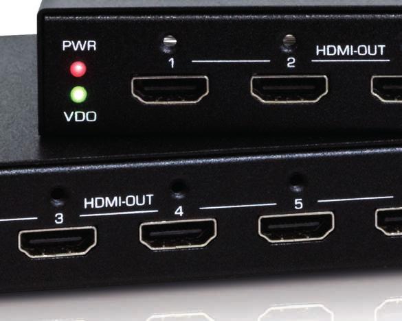
4 5. POSITION DER VIDEOWAND Anhand der folgenden Abbildung können Sie das Layout und die Position der Bildschirme konfigurieren. Die Ziffer von 1 bis 9 entspricht den Anschlüssen auf der Rückseite des Videowand-Controllers LIEFERUMFANG Videowand-Verteiler 4-fach / 9-fach Bedienungsanleitung Infrarot-Fernbedienung Netzteil IR-Verlängerung Kit zur Wandbefestigung 7. PRODUKTÜBERSICHT Front: Rückseite:
5 Nr. Element Beschreibung 1 Power Anzeige Leuchtet im Betrieb 2 Video Anzeige 1. Leuchtet, wenn die Videoquelle angeschlossen ist. 2. Blinkt, wenn sich das Gerät im Upgrade-Modus befindet. 3 HDMI Ausgänge Schließen Sie die Monitore der Videowand an. 4 HDMI Verriegelung Unterstützt die HDMI Lock Sicherheitsverschraubung 5 IR Empfänger Empängt die Signale der Fernbedienung 6 DC Strombuchse Zum Anschluss des Netzteils, kann verriegelt werden 7 Buchse für die IR-Verlängerung Zum Anschluss der Infrarot-Verlängerung 8 Reset Um auf den Systemstandard zurückzusetzen oder das System zu aktualisieren. 9 Mini-USB Anschluss Zur Firmware-Aktualisierung 10 HDMI Eingang Zum Anschluss einer HDMI Quelle (Computer, Mediaplayer, etc.) 11 HDMI Verriegelung Unterstützt die HDMI Lock Sicherheitsverschraubung 12 VGA Eingang Zum Anschluss einer VGA Quelle 13 Audio Eingang Zum Anschluss der zum VGA Eingang gehörenden Audioquelle. 8. BEDIENUNG Fernbedienung Die Steuerung der Videowand erfolgt i. d. R. über die Fernbedienung. Sie können den Verteiler über die Fernbedienung einfach einrichten und in verschiedene Anzeigemodi wechseln. Lesen Sie die folgenden Beschreibungen, um die Details zu sehen I Nr. Element / Taste Beschreibung 1 2x2 Schaltet den Anzeigemodus auf 2x2 um. 2 1x4 Schaltet den Anzeigemodus auf 1x4 um. (4 Monitore horizontal in einer Reihe) 3 SETUP Drücken Sie diese Taste, um das OSD-Menü aufzurufen. 4 / / / /OK (Pfeiltasten) 1. / / / : Drücken Sie diese Taste, um den Cursor im Menü nach oben, unten, links und rechts zu navigieren. 2. OK: Bestätigen Sie die Auswahl 5 SPLITTER Drücken Sie diese Taste, um die Videoquelle von einem auf mehrere Monitore zu verteilen (bis zu 4 Monitore, gleiches Bild auf allen Monitoren). 6 4x1 Schaltet den Anzeigemodus auf 1x4 um. (4 Monitore vertikal in einer Spalte) 7 MUTE Drücken Sie diese Taste, um den Ton auszuschalten. 8 EXIT Drücken Sie diese Taste, um das OSD-Menü zu verlassen info@inline-info.com 5
6 I Nr. Element / Taste Beschreibung 1 3x3 Schaltet den Anzeigemodus auf 3x3 um. 2 2x4 Schaltet den Anzeigemodus auf 2x4 um. (jeweils 4 Monitore horizontal in 2 Reihen) 3 SETUP Drücken Sie diese Taste, um das OSD-Menü aufzurufen. 4 / / / /OK (Pfeiltasten) 1. / / / : Drücken Sie diese Taste, um den Cursor im Menü nach oben, unten, links und rechts zu navigieren. 2. OK: Bestätigen Sie die Auswahl 5 SPLITTER Drücken Sie diese Taste, um die Videoquelle von einem auf mehrere Monitore zu verteilen (bis zu 9 Monitore, gleiches Bild auf allen Monitoren). 6 4x2 Schaltet den Anzeigemodus auf 4x2 um. ( jeweils 4 Monitore vertikal in 2 Spalten) 7 MUTE Drücken Sie diese Taste, um den Ton auszuschalten. 8 EXIT Drücken Sie diese Taste, um das OSD-Menü zu verlassen KONFIGURATION 1. Drücken Sie die Taste SETUP, um das OSD-Menü mit der Fernbedienung aufzurufen. 2. Drücken Sie die Pfeiltasten, um die Option auszuwählen und anzupassen. 3. Wählen Die EXIT, um das OSD-Menü zu verlassen. a. Einstellen der horizontalen Verzerrung 6
7 1. Wählen Sie mit Hilfe der Pfeiltasten oder den Menüpunkt Horizontal Bezel, und drücken Sie dann die OK-Taste, um die Option aufzurufen. 2. Die Einstellung der horizontalen Verschiebung liegt zwischen Drücken Sie oder, um den Versatz einzustellen. Beachten Sie, dass der einstellbare Wertebereich dynamisch ist, er hängt von der Ausgabeauflösung ab, die Sie unter Select resolution einstellen. So kann es beispielsweise vorkommen, dass sich die Kompensation nicht ändert, wenn der Wert größer als eingestellt wird. 3. Drücken Sie OK, um die Einstellung zu bestätigen, und drücken Sie dann Exit, um zum vorherigen Menü zurückzukehren. b. Einstellen der vertikalen Verzerrung 1. Wählen Sie mit Hilfe der Pfeiltasten oder den Menüpunkt Vertical Bezel, und drücken Sie dann die OK-Taste, um die Option aufzurufen. 2. Die Einstellung der horizontalen Verschiebung liegt zwischen Drücken Sie oder, um den Versatz einzustellen. Beachten Sie, dass der einstellbare Wertebereich dynamisch ist, er hängt von der Ausgabeauflösung ab, die Sie unter Select resolution einstellen. So kann es beispielsweise vorkommen, dass sich die Kompensation nicht ändert, wenn der Wert größer als eingestellt wird. 3. Drücken Sie OK, um die Einstellung zu bestätigen, und drücken Sie dann Exit, um zum vorherigen Menü zurückzukehren. c. Größeneinstellung 1. Drücken Sie oder, um Crop zu wählen, und drücken Sie dann die OK-Taste, um die Option aufzurufen. Beachten Sie, dass die Einstellung des Crop Level nur auf der Videowand (2x2, 1x4, 4x2) verfügbar ist, im Splitter-Modus ist diese Option nicht verfügbar. 7
8 2. Drücken Sie oder, um Crop level auszuwählen, und drücken Sie dann die OK-Taste, ein roter Rahmen erscheint auf dem Bildschirm. Die Position des Rahmens bezieht sich auf den Monitor, den Sie an den Anschluss von HDMI 4 am Controller angeschlossen haben. 3. Drücken Sie oder, um die gewünschte Größe einzustellen. Der Wert von Crop level liegt zwischen 00-10, die entsprechenden Auflösungen finden Sie in der folgenden Tabelle. Crop Level Auflösung x1080 (16:9) x1080 (16:9) x1026 (16:9) x972 (16:9) x918 (16:9) x864 (16:9) x810 (16:9) x756 (16:9) x702 (16:9) x648 (16:9) x594 (16:9) d. Positionseinstellung 1. Sobald die Größenkonfiguration eingestellt ist, drücken Sie oder, wählen Sie Crop position auf der Seite Crop Settings und drücken Sie OK zur Bestätigung. 2. Drücken Sie / / /, um die gewünschte Position einzustellen. 3. Drücken Sie OK, um die Einstellung zu bestätigen, und drücken Sie dann Exit, um zum vorherigen Menü zurückzukehren. Der gewählte Bildausschnitt wird nun vergrößert auf die Videowand verteilt. e. Auswahl der Auflösung 1. Drücken Sie oder, um Output Resolution auszuwählen, und drücken Sie dann die OK-Taste, um die Option aufzurufen. 8
9 2. Drücken Sie oder, um eine gewünschte Auflösung zu wählen. Die Optionen beinhalten: Auto, 1080p60, 1080i60, 1080p30, 720p60 und 720p Drücken Sie OK, um die Einstellung zu bestätigen, und drücken Sie dann Exit, um zum vorherigen Menü zurückzukehren. 4. Die unterstützte Eingangsauflösung entnehmen Sie bitte der folgenden Tabelle: Pro Monitor 1920x x x x x x x x x FIRMWARE VERSION Zeigt die derzeitige Firmware Version an. 11. DAS SYSTEM ZURÜCKSETZEN Halten Sie die Reset-Taste 5 Sekunden lang gedrückt, wenn das Gerät eingeschaltet ist. 12. AUSWAHL DER FERNBEDIENUNG Befolgen Sie die Schritte zur Auswahl der spezifischen Steuerung, wenn die Videowandanwendung von mehreren Steuerungen gleichzeitig kombiniert wird. 1. Drücken Sie die Taste Setup, um das OSD-Menü mit der Fernbedienung aufzurufen. 2. Drücken Sie oder, um Remote Controller zu wählen, und drücken Sie dann OK. 3. Die aktuelle Fernbedienungs-ID wird auf dem Bildschirm angezeigt, drücken Sie oder, um die gewünschte ID der Fernbedienung auszuwählen, und drücken Sie dann OK, um zur vorherigen Seite zurückzukehren. 4. Drücken Sie auf Exit, um das OSD-Menü zu verlassen, ein Bestätigungsfenster erscheint im Fenster, drücken Sie auf Yes, um die Einstellungen zu speichern und zu beenden. info@inline-info.com 9
10 5. Stellen Sie den DIP-Schalter nun so ein, dass er mit der Einstellung im OSD-Menü übereinstimmt. Sie können die folgende Abbildung für die Referenz der Jumperposition verwenden. Öffnen Sie die Batterieabdeckung der Fernbedienung und entfernen Sie die Batterien auf dem Bedienfeld der Fernbedienung, stellen Sie dann die Jumperblöcke entsprechend der ID der Einstellung unter Punkt 3 ein. ID1 ID2 ID3 ID4 13. WIEDERHERSTELLEN DER WERKSEINSTELLUNGEN Standardmäßig ist der DIP-Schalter auf ID 1 eingestellt. Wenn Sie die Verbindung verloren und die Konfiguration zwischen der ID-Einstellung im OSD-Menü und dem DIP-Schalter auf der Fernbedienung vergessen haben, stellen Sie die Werkseinstellung wieder her. Halten Sie hierzu Sie die Reset-Taste beim Einschalten 5 Sekunden lang gedrückt und stellen die Fernbedienung auf ID TECHNISCHER SUPPORT Bitte kontaktieren Sie Ihren lokalen Vertriebspartner oder die Herstellerwebseite ( für weitere Informationen oder technischen Support. 15. DISCLAIMER 1. Ausgabe Deutsch 40/2018 Dokumentation 2018 INTOS ELECTRONIC AG Alle Rechte vorbehalten. Ohne schriftliche Zustimmung des Herausgebers darf dieses Handbuch auch nicht auszugsweise in irgendeiner Form reproduziert werden oder unter Verwendung elektronischer, mechanischer oder chemischer Verfahren vervielfältigt oder verarbeitet werden. Es ist möglich, dass das vorliegende Handbuch noch drucktechnische Mängel oder Druckfehler aufweist. Die Angaben in diesem Handbuch werden jedoch regelmäßig überprüft und Korrekturen in der nächsten Ausgabe vorgenommen. Für Fehler technischer oder drucktechnischer Art und ihre Folgen übernehmen wir keine Haftung. Alle Warenzeichen und Schutzrechte werden anerkannt. Änderungen im Sinne des technischen Fortschritts können ohne Vorankündigung vorgenommen werden. Unsere Produkte, einschließlich der Verpackung, sind kein Spielzeug, sie könnten kleine Teile und scharfe Objekte enthalten. Bitte von Kindern fernhalten. InLine ist eine Marke der: INTOS ELECTRONIC AG Siemensstrasse 11, D Giessen 10
11 EN CONTENT 1. Introduction Features Specification Connection diagram Video wall position Package contents Product overview Operation Configuration a. Adjust the horizontal bezel b. Adjust the vertical bezel c. Size adjustment d. Position adjustment e. Select the resolution Firmware Version Reset the system Remote controller selection Restore the factory default Technical Support Disclaimer INTRODUCTION Thank you for purchasing the InLine HDMI Video Wall Distributor 4-way / 9-way. This stand-alone video wall controller has been designed to use high-quality multiple displays and can duplicate or enlarge a video source and distribute it to up to nine monitors. With the InLine HDMI Video Wall Distributor you can combine 4 (art. no I) or 9 (art. no I) monitors with a max. screen resolution of 1920x1200 to a large video wall (2x2 or 3x3 monitors). For the input signal you have an HDMI or VGA interface available. The InLine HDMI Video Wall Distributor is easily controlled via an IR remote control. The extended frame compensation can help to optimally adapt the picture to the video wall. The InLine HDMI Video Wall Distributor is the ideal solution for all professional video applications such as digital signage, advertising, A/V splitting or broadcasting. info@inline-info.com 11
12 2. FEATURES Create a 2x2, 1x4, 4x1 (57834I) or 3x3, 4x2, 2x4 (57839I) video wall from any Hi-Def source, using four / nine HDTV displays Split and scale a single Hi-Def source to four / nine displays Input and Output resolutions up to 1080p Full HD and 1920x1200 (WUXGA) with HDCP compliant Easy to use on-screen display user interface Advanced Bezel Compensation feature provides compatibility with virtually any screen frame width, and allows for accurate display of the image IR remote control USB port for upgrade (reserved for future product enhancements) Locking power supply connector Wall-mountable enclosure, mount ears included 3. SPECIFICATION Item number 57834I 57839I Dimension (L x W x H) 120 x 134 x 26mm 238 x 134 x 26mm Weight 470g 870g Video Out HDMI x 4 HDMI x 9 Video In HDMI x 1(Lockable), VGA x 1 Audio In 3.5mm Earphone Jack x1 USB Mini USB x 1 IR 1 x Receiver, 1 x IR Extender (3.5mm Earphone Jack) LED Indicator Red x 1 (Power), Green x 1 (Video) Power Adapter 5V4A (with lock) Housing Metal Operation Temperature 0 ~ 40 C Storage Temperature -20 ~ 60 C Humidity 0~90% RH, Non-condensing 4. CONNECTION DIAGRAM The diagram illustrated here is an example of 57834I video wall controller, the actual application may vary. All illustrated computer, accessories and monitors are not included in the package, it is for reference only. Make sure all the devices and peripherals are connected appropriately before using this unit. To connect the 57839I, the connection is similar to 57834I. The difference between the two devices is only the number of monitors connected together I Front 57834I Rear Power adapter Monitors IR extender (optional) Media player or PC 12
13 5. VIDEO WALL POSITION Refer to the illustration below to configure the layout and screens position. The numeral from 1 to 9 corresponds to the connectors on the rear panel of video wall controller PACKAGE CONTENTS 57834I/57839I unit x1 User manual x1 Remote control x1 Power adapter x1 IR extender x1 (optional) Wall mount kit x1 7. PRODUCT OVERVIEW Front panel: Rear panel: info@inline-info.com 13
14 No. Item Description 1 Power indicator Lights when power is on. 2 Video indicator 1. Lights when video source is connecting. 2. Flashes when the video wall controller is in upgrade mode. 3 HDMI outputs Connect to the HDMI connectors of video wall. 4 HDMI port lock Secures the HDMI cable. 5 IR receiver Receives the signal from the remote control. 6 Power jack Connect to the power adapter. 7 IR extender 3.5mm jack Connect to the IR extender. 8 Reset Reset to the system default or upgrade the system. For more details, refer to the descriptions on page Mini USB connector Connect to upgrade the system. 10 HDMI input Connect to an HDMI source such as a PC or player. 11 HDMI port lock Secures the HDMI cable. 12 VGA input Connect to PC s VGA connector. 13 Audio input Connect to PC s audio out jack. 8. OPERATION Remote control The video wall is usually controlled via the remote control. You can easily set up the distributor via the remote control and switch to different display modes. Read the following descriptions to see the details I No. Item Description 1 2x2 Switch the display mode into 2x2. 2 1x4 Switch the display mode into 1x4. 3 SETUP Press to access the OSD menu. 4 / / / /OK (Cursor buttons) 1. / / / : Press to move the cursor up, down, left and right on the menu. 2. OK: Confirm the selection 5 SPLITTER Press to distribute the video source from one to multiple up to x1 Switch the display mode into 4x1. 7 MUTE Press to turn off the audio. 8 EXIT Press to exit the OSD menu
15 57839I No. Item Description 1 3x3 Switch the display mode into 3x3. 2 2x4 Switch the display mode into 2x4. 3 SETUP Press to access the OSD menu. 4 / / / /OK (Cursor buttons) 1. / / / : Press to move the cursor up, down, left and right on the menu. 2. OK: Confirm the selection 5 SPLITTER Press to distribute the video source from one to multiple up to x2 Swtich the display mode into 4x2. 7 MUTE Press to turn off the audio. 8 EXIT Press to exit the OSD menu CONFIGURATION 1. Press the button of SETUP to bring up the OSD menu using the remote control. 2. Press / / / to select and adjust the option. 3. Press EXIT to exit the OSD menu. a. Adjust the horizontal bezel The remote control is the main type of video wall control. The user can easily set up via the remote control and switch to different display modes. Read the following descriptions to see the details. info@inline-info.com 15
16 1. Press or to select Vertical bezel, and then press OK button to bring up option. 2. The setting of vertical bezel is between 00~10. Press or to adjust the bezel. Note that the adjustable range of value is dynamic, it depends on the output resolution you set from Select resolution. For example, the bezel compensation may not change when adjusting the value more than 06~ Press OK to confirm the adjustment, and then press Exit to return to the previous menu. b. Adjust the vertical bezel 1. Press or to select vertical bezel, and then press OK button to bring up option. 2. The setting of vertical bezel is between 00~10. Press or to adjust the bezel. Note that the adjustable range of value is dynamic, it depends on the output resolution you set from Select resolution. For example, the bezel compensation may not change when adjusting the value more than 06~ Press OK to confirm the adjustment, and then press Exit to return to the previous menu. c. Size adjustment 1. Press or, to select Crop, and then press OK button to bring up option. Note that the setting of Crop level is only available on video wall (2x2, 1x4, 4x2), the Splitter mode is not available for the adjustment. 2. Press or, to select Crop level, and then press OK button. A red frame will appear on the screen. The location of frame is based on the monitor you connected to the port of HDMI 4 on the controller. 3. Press or to adjust the desired size. The value of Crop level is between 00~10. You may refer to the table below for the corresponding resolutions. 16
 10 1056x594 (16:9) d. Position adjustment 1. Once the size configuration has been set, press or to select Crop position on the Crop Settings page and press OK to enter. 2.")
17 Crop level Resolution x1080 (16:9) x1080 (16:9) x1026 (16:9) x972 (16:9) x918 (16:9) x864 (16:9) x810 (16:9) x756 (16:9) x702 (16:9) x648 (16:9) x594 (16:9) d. Position adjustment 1. Once the size configuration has been set, press or to select Crop position on the Crop Settings page and press OK to enter. 2. Press / / / to adjust the desired position. 3. Press OK to confirm the adjustment, and then press Exit to return to the previous menu. The selected image section will now be enlarged on the video wall. e. Select the resolution 1. Press or to select output resolution, and then press OK button to bring up option. 2. Press or, to select a desired resolution. The options are including: Auto, 1080p60, 1080i60, 1080p30, 720p60 and 720p30. info@inline-info.com 17
18 3. Press OK to confirm the adjustment, and then press Exit to return to the previous menu. 4. For the supported input resolution, refer to the table below: Each monitor 1920x x x x x x x x x FIRMWARE VERSION Display the current firmware version. 11. RESET THE SYSTEM Press and hold the reset button for 5 seconds when the power is on. 12. REMOTE CONTROLLER SELECTION Follow the steps to select the specific controller if the video wall application is combined by several controllers simultaneously. 1. Press the button of Setup to bring up the OSD menu using the remote control. 2. Press or to select Remote controller, and then press OK. 3. The current remote control ID will be displayed on the screen, press or to select the desired ID of remote control and then press OK to return to the previous page. 4. Press Exit to exit the OSD menu, a confirmation window will pop-up on the window, press Yes to save the settings and exit. 18
19 5. Adjust the DIP switch to match the setting on the OSD menu. You may refer to the illustration below for the reference of jumper position. Open the battery cover and remove the batteries on the rear panel of remote control, and then adjust the jumper blocks using a gadget according to your requirement. ID1 ID2 ID3 ID4 13. RESTORE THE FACTORY DEFAULT By default, the DIP switch is set to ID 1. If you have lost the connection and forgotten the configuration between the ID setting in the OSD menu and the DIP switch on the remote control, restore the factory setting. To do this, press and hold the reset button for 5 seconds during power-up the device and set the remote control to ID TECHNICAL SUPPORT Please contact your local distributor or the manufacturer s website ( for further information or technical support. 15. DISCLAIMER 1st edition English 40/2018 Documentation 2018 INTOS ELECTRONIC AG All rights reserved. No part of this manual may be reproduced in any form or reproduced or processed using electronic, mechanical or chemical processes without the written consent of the publisher. It is possible that this manual still has printing defects or printing errors. However, the information in this manual will be reviewed regularly and corrections will be made in the next edition. We accept no liability for technical or printing errors and their consequences. All trademarks and industrial property rights are acknowledged. Changes in line with technical progress may be made without prior notice. Our products, including the packaging, are not toys, they may contain small parts and sharp objects. Please keep away from children. InLine is a brand of: INTOS ELECTRONIC AG Siemensstrasse 11, D Giessen info@inline-info.com 19


20 FRAGEN ZU PRODUKTEN ODER ZUR TECHNIK? QUESTIONS ABOUT OUR PRODUCTS OR THE TECHNOLOGY? DE Kaufberatung, Hilfe bei technischen Fragen und der Installation direkt vom Hersteller. Montag bis Freitag von 9 bis 17 Uhr persönlich für Sie. EN Get your support for technical and installation issues or purchase advice directly from the manufacturer. Monday to Friday from 9 to 5pm. Wir helfen das passende Produkt für Ihren Bedarf zu finden, sind bei der Bezugsquellensuche behilflich, beantworten technische Fragen und unterstützen Sie bei der Installation Ihrer InLine Produkte, z. B. mit den aktuellsten Treibern. We will help you to find suitable products for your needs, we provide support in finding supply sources, answer technical questions and gladly help you to install your InLine products e.g. by providing up-to-date drivers. live.inline-info.com ANWENDUNGSBEISPIEL APPLICATION EXAMPLE
EL-21SY. 2 in, 1 out v1.3 HDMI Switcher OPERATION MANUAL
 EL-21SY 2 in, 1 out v1.3 HDMI Switcher OPERATION MANUAL Table of Contents 1. Introduction 1 2. Features 1 3. Package Contents 1 4. Operation Controls and Functions 2 4.1 Front Panel Diagram 2 4.2 Rear
SETUP TOOL. Bedienungsanleitung User s Manual
 Bedienungsanleitung User s Manual Bitte lesen Sie diese Anleitung vor der Inbetriebnahme sorgfältig durch Please read the instructions carefully before use 1. Eigenschaften Das Setup Tool ist ein speziell
INDEX. 3. Package Contents Connection and Operation...4
 3 - P O R T H D M I S w i t c h V i s i o n 3 3 2 7 0 3 INDEX 1. I n t r o d u c t i o n... 2 2. S p e c i f i c a t i o n s... 3 3. Package Contents...3 4. P a n e l D e s c r i p t i o n s.. 4 5. Connection
AU-D2. Coaxial/Optical Audio Converter OPERATION MANUAL
 AU-D2 Coaxial/Optical Audio Converter OPERATION MANUAL Table of Contents 1. Introduction 1 2. Features 1 3. Operation Controls and Functions 2 3.1 Input Panel Diagram 2 3.2 Output Panel Diagram 2 3.3 Switcher
QU-12S. v1.3 HDMI Distribution Amplifier OPERATION MANUAL
 QU-12S v1.3 HDMI Distribution Amplifier OPERATION MANUAL Table of Contents 1. Introduction 1 2. Features 1 3. Package Contents 1 4. Operation Controls and Functions 2 4.1 Front Panel Diagram 2 4.2 Rear
VN7640 FlexRay/CAN/LIN/Ethernet Interface Quick Start Guide. Version 1.1 English/Deutsch
 VN7640 FlexRay/CAN/LIN/Ethernet Interface Quick Start Guide Version 1.1 English/Deutsch Quick Start Guide VN7640 ENGLISH 1 ENGLISH 1.1 Installation Step by Step Procedure Please use the drivers from the
USB -> Seriell Adapterkabel Benutzerhandbuch
 USB -> Seriell Adapterkabel Benutzerhandbuch 1. Produkt Eigenschaften 1 2. System Vorraussetzungen 1 3. Treiber Installation (Alle Windows Systeme) 1 4. Den COM Port ändern 2 5. Einstellen eines RS232
A VGA monitor of the highest resolution that you will be using on any computer in the installation A PS/2 Keyboard A PS/2 Mouse
 PS/2 KVM SWITCH 2-PORT Vision 331217 Requirements Console A VGA monitor of the highest resolution that you will be using on any computer in the installation A PS/2 Keyboard A PS/2 Mouse Computers The following
Tube Analyzer LogViewer 2.3
 Tube Analyzer LogViewer 2.3 User Manual Stand: 25.9.2015 Seite 1 von 11 Name Company Date Designed by WKS 28.02.2013 1 st Checker 2 nd Checker Version history Version Author Changes Date 1.0 Created 19.06.2015
UCON UCON Kurzanleitung Inbetriebnahme
 UCON UCON Kurzanleitung Inbetriebnahme copyright G&D 24/08/2005 Irrum und techn. Änderungen vorbehalten 1. Was Sie zur Installation benötigen - UCON - 1:1 belegtes CAT-x Patchkabel - Kaltgerätekabel -
Monitor VIS 3xx Kurzanleitung
 Monitor VIS 3xx Kurzanleitung 19.08.08 Art. Nr. 22261 Inhalt: 1. Spezifikationen...2 2. Tastenfunktionen...2 3. Menüführung und Einstellungen...3 Technik nach Maß Wöhler Monitor VIS 3xx 1. Spezifikationen
SY-720SC. SCART to HDMI Scaler OPERATION MANUAL
 SY-720SC SCART to HDMI Scaler OPERATION MANUAL Table of Contents 1. Introduction 1 2. Features 1 3. Package Contents 1 4. Operation Controls and Functions 1 4.1 Scart Pinout Configuration 2 5. Connection
Quick Installation Guide
 LevelOne WHG-1000 300Mbps Wireless PoE Hotspot Gateway Quick Installation Guide English Deutsch Table of Contents English... 3 Deutsch... 13 Default Settings IP Address-LAN1 192.168.1.254 IP Address-LAN2
AU-D21. Digital Audio Optical Switcher OPERATION MANUAL
 AU-D21 Digital Audio Optical Switcher OPERATION MANUAL Table of Contents 1. Introduction 1 2. Features 1 3. Operation Controls and Functions 2 3.1 Front Panel Diagram 2 3.2 Rear Panel Diagram 2 3.3 Side
UCON/s UCON/s Kurzanleitung Inbetriebnahme
 UCON/s UCON/s Kurzanleitung Inbetriebnahme copyright G&D 24/08/2005 Irrum und techn. Änderungen vorbehalten 1. Was Sie zur Installation benötigen - UCON/s - 1:1 belegtes CAT-x Patchkabel - CATPRO2(bei
Word-CRM-Upload-Button. User manual
 Word-CRM-Upload-Button User manual Word-CRM-Upload for MS CRM 2011 Content 1. Preface... 3 2. Installation... 4 2.1. Requirements... 4 2.1.1. Clients... 4 2.2. Installation guidelines... 5 2.2.1. Client...
Quick Guide Home Network Mode
 Quick Guide Home Network Mode English > 1 German > 3 About the Home Network Mode EN Tivizen Nano & iplug normally work on their own created networks (whose SSID starts with tivizentv or iplug ) in which
Bedienungsanleitung. User Manual. FLAT PAR TRI 5x3W TRI, IR Remote LIG
 Bedienungsanleitung User Manual FLAT PAR TRI 5x3W TRI, IR Remote LIG0010659-000 Lieber Kunde, vielen Dank das Sie sich für ein Produkt von LightmaXX entschieden haben. In der folgenden Anleitung erhalten
ITAC Bedienungsanleitung User manual. Originalbedienungsanleitung in deutscher Sprache. Für künftige Verwendung aufbewahren.
 D Bedienungsanleitung User manual Originalbedienungsanleitung in deutscher Sprache. Für künftige Verwendung aufbewahren. This user manual contains important information for installation and operation.
mobilcom-debitel SmartHome Schnell-Start-Anleitung Quick Start Guide
 mobilcom-debitel SmartHome Schnell-Start-Anleitung Quick Start Guide 1. Cube anschließen 1. Connect Cube n Schließen Sie den Cube an die Stromversorgung an. n Legen Sie die Batterien polungsrichtig in
USB-C Multiport Adapter
 USB-C Multiport Adapter User Guide English USB-C Multiport Adapter Unlock the full potential of your Apple MacBook MINIX s USB-C Multiport Adapter is the world s most advanced USB-C adapter, delivering
EMCO Installationsanleitung / Installation instructions
 EMCO Installationsanleitung / Installation instructions Installationsanleitung Installation instructions Digitalanzeige digital display C40, FB450 L, FB600 L, EM 14D/17D/20D Ausgabe / Edition B 2012-03
VGM. VGM information. HAMBURG SÜD VGM WEB PORTAL USER GUIDE June 2016
 Overview The Hamburg Süd VGM Web portal is an application that enables you to submit VGM information directly to Hamburg Süd via our e-portal Web page. You can choose to enter VGM information directly,
Bedienungsanleitung. User Manual
 Bedienungsanleitung Seite: -3 User Manual LightmaXX 5ive STAR LED LIG0009669-000 Page: 4-5 Lieber Kunde, vielen Dank das Sie sich für ein Produkt von LightmaXX entschieden haben. In der folgenden Anleitung
Hama GmbH & Co KG Postfach Monheim/Germany Tel. +49 (0)9091/502-0 Fax +49 (0)9091/
9091/502-0 Fax +49 (0)9091/") www.hama.de Hama GmbH & Co KG Postfach 80 86651 Monheim/Germany Tel. +49 (0)9091/502-0 Fax +49 (0)9091/502-274 hama@hama.de www.hama.de 00062249-05.05 Multimedia Kit für/for Mercedes Command 2.0 00062249
www.hama.de Hama GmbH & Co KG Postfach 80 86651 Monheim/Germany Tel. +49 (0)9091/502-0 Fax +49 (0)9091/502-274 hama@hama.de www.hama.de 00062249-05.05 Multimedia Kit für/for Mercedes Command 2.0 00062249
Laser LightmaXX CLUB 2.0 / 4.0 SERIES
 Seite 1 von 8 Laser LightmaXX CLUB 2.0 / 4.0 SERIES ACHTUNG! Seite 2 von 8 Laserschutzbestimmungen: Durch die starke Bündelung des Laserstrahls ist die gesamte Lichtenergie auf eine geringe Fläche konzentriert.
AU-D4T. Analogue to Digital Audio Converter with Audio delay OPERATION MANUAL
 AU-D4T Analogue to Digital Audio Converter with Audio delay OPERATION MANUAL Table of Contents 1. Introduction 1 2. Features 1 3. Package Contents 1 4. Operation Controls and Functions 2 4.1 Front Panel
Installationsanleitung
 Installationsanleitung 57831I InLine DisplayPort zu 4-Port HDMI-Videowand Verteiler 1. EINFÜHRUNG Wir gratulieren zum Kauf des DisplayPort zu 4-Port HDMI-Videowand Verteilers. Dieses zuverlässige und qualitativ
miditech 4merge 4-fach MIDI Merger mit :
 miditech 4merge 4-fach MIDI Merger mit : 4 x MIDI Input Port, 4 LEDs für MIDI In Signale 1 x MIDI Output Port MIDI USB Port, auch für USB Power Adapter Power LED und LOGO LEDs Hochwertiges Aluminium Gehäuse
Bedienungsanleitung. User Manual
 Bedienungsanleitung Seite: 1-6 User Manual Platinum Line Mini PAR QUAD 7x 8 Watt QUAD LED (RGBW) LIG0009429-000 / LIG0009430-000 Page: 7-10 Lieber Kunde, vielen Dank das Sie sich für ein Produkt von LightmaXX
AU-D4. Analogue to Digital Audio Converter OPERATION MANUAL
 AU-D4 Analogue to Digital Audio Converter OPERATION MANUAL Table of Contents 1. Introduction 1 2. Features 1 3. Package Contents 1 4. Operation Controls and Functions 2 4.1 Front Panel Diagram 2 4.2 Rear
Softwareupdate-Anleitung // Porty L 600 / Porty L 1200
 Softwareupdate-Anleitung // Porty L 600 / Porty L 1200 1 Softwareupdate-Anleitung // Porty L 600 / Porty L 1200 HENSEL-VISIT GmbH & Co. KG Robert-Bunsen-Str. 3 D-97076 Würzburg-Lengfeld GERMANY Tel./Phone:
AU-D7. Audio Processor - Virtual 5.1 Encoder OPERATION MANUAL
 AU-D7 Audio Processor - Virtual 5.1 Encoder OPERATION MANUAL Table of Contents 1. Introduction 1 2. Features 1 3. Operation Controls and Functions 2 3.1 Front Panel Diagram 2 3.2 Rear Panel Diagram 2 3.3
Cameraserver mini. commissioning. Ihre Vision ist unsere Aufgabe
 Cameraserver mini commissioning Page 1 Cameraserver - commissioning Contents 1. Plug IN... 3 2. Turn ON... 3 3. Network configuration... 4 4. Client-Installation... 6 4.1 Desktop Client... 6 4.2 Silverlight
HDTV cinematic feeling with all HDMI 2.0 features, improved haptics and design packaging
 HDTV cinematic feeling with all HDMI 2.0 features, improved haptics and design packaging The Cinema Series from PureLink sets an example with sophisticated and future-proof technology when it comes to
Bedienungsanleitung / Manual : LED-Nixie
 Bedienungsanleitung / Manual : LED-Nixie English please see below. Bei Neustart und gleichzeitig gedrückter Taste während der Versionsanzeige (halten bis Beep hörbar), erfolgt eine Zurücksetzung auf (Standard)
UWC 8801 / 8802 / 8803
 Wandbedieneinheit Wall Panel UWC 8801 / 8802 / 8803 Bedienungsanleitung User Manual BDA V130601DE UWC 8801 Wandbedieneinheit Anschluss Vor dem Anschluss ist der UMM 8800 unbedingt auszuschalten. Die Übertragung
Bedienungsanleitung Manual
 NK ZSU 2 ZEITSCHALTUHR DIGITAL 51277 NK ZSU 3 ZEITSCHALTUHR DIGITAL IP44 51301 NK ZSU 4 ZEITSCHALTUHR DIGITAL 93256 NK ZSU 2 TIME SWITCH DIGITAL 51277 NK ZSU 3 TIME SWITCH DIGITAL IP44 51301 NK ZSU 4 TIME
DATENBLATT / DATASHEET
 DATENBLATT / DATASHEET AEQUILUX DMX PLAYER 1024 / 2048 Abb. Ähnlich Illustration similar BESCHREIBUNG / DESCRIPTION Der AEQUILUX DMX Player dient zur Lichtsteuerung des AEQUILUX Systems. Das Gerät kann
Einrichtung - Windows
 EPSON TM-T88V Serie How Do I NCCR 9.00 für Microsoft Dynamics NAV 2016* *NC Cash Register 9.00 ist verfügbar für Microsoft Dynamics NAV 5.0 SP1, Microsoft Dynamics NAV 2013, Microsoft Dynamics NAV 2013
Kurzanleitung um Transponder mit einem scemtec TT Reader und der Software UniDemo zu lesen
 Kurzanleitung um Transponder mit einem scemtec TT Reader und der Software UniDemo zu lesen QuickStart Guide to read a transponder with a scemtec TT reader and software UniDemo Voraussetzung: - PC mit der
Hama GmbH & Co KG Postfach Monheim/Germany Tel. +49 (0)9091/502-0 Fax +49 (0)9091/
9091/502-0 Fax +49 (0)9091/") www.hama.de Hama GmbH & Co KG Postfach 80 86651 Monheim/Germany Tel. +49 (0)9091/502-0 Fax +49 (0)9091/502-274 hama@hama.de www.hama.de 00062248-05.05 Multimedia Kit für/for Audi Naviplus/ VW/Seat/Skoda
www.hama.de Hama GmbH & Co KG Postfach 80 86651 Monheim/Germany Tel. +49 (0)9091/502-0 Fax +49 (0)9091/502-274 hama@hama.de www.hama.de 00062248-05.05 Multimedia Kit für/for Audi Naviplus/ VW/Seat/Skoda
p^db=`oj===pìééçêíáåñçêã~íáçå=
 p^db=`oj===pìééçêíáåñçêã~íáçå= Error: "Could not connect to the SQL Server Instance" or "Failed to open a connection to the database." When you attempt to launch ACT! by Sage or ACT by Sage Premium for
Anleitung zur Verwendung des Update-Tools für
 English version see below (page 10) Anleitung zur Verwendung des Update-Tools für - KW DDC Steuergeräte - KW DDC WLAN Module - KW DLC Steuergeräte - KW DLC WLAN Module Bitte beachten Sie: jedes Steuergerät
PoE Kit Mounting Instructions SG/XG 210/230/310/330/430/450
 PoE Kit Mounting Instructions PoE Kit Mounting Instructions Please note ÌÌ Before installing/removing any LAN module please make sure that the appliance is powered off and power cables are removed. ÌÌ
ODYS 19 LCD-TV VIEW ODYS 19 LCD-TV VIEW
 Anschlusskabel POWER Einschalten des Fernsehers MUTE Stummschaltung NICAM Umschalten des Soundsystems SLEEP Sleep-Timer einschalten ASPECT Umschalten des Bildseitenverhältnisses zwischen 4:3, 16:9,
Dexatek's Alexa Smart Home Skills Instruction Guide
 Dexatek's Alexa Smart Home Skills Instruction Guide Version 0.3 Author Esther Date 01/10/18 ~ 1 ~ Revision History Version Date Editor Remark 0.1 2017/04/05 Esther Initial version 0.2 2018/01/09 Esther
TOUCH CONTROL GLASS RGB DMX
 Bedienungsanleitung User s Manual Eigenschaften DMX 512 Stand Alone Controller mit Glasoberfläche Kompatibel mit allen DMX Einheiten oder DMX LED Geräten Betriebsbereit (vorprogrammiert mit 8 Szenen und
APPMODULE A:SMB DOCUMENTATION. v Alto HiFi AG Gublenstrasse 1 CH-8733 Eschenbach tel +41 (0)
") APPMODULE A:SMB DOCUMENTATION v1.2.00 Alto HiFi AG Gublenstrasse 1 CH-8733 Eschenbach tel +41 (0)55 254 90 90 altohifi.ch 1 Inhaltsverzeichnis 1. Funktion 3 2. Anwendung 3 3. Lizenzen 3 4. Konfiguration
APPMODULE A:SMB DOCUMENTATION v1.2.00 Alto HiFi AG Gublenstrasse 1 CH-8733 Eschenbach tel +41 (0)55 254 90 90 altohifi.ch 1 Inhaltsverzeichnis 1. Funktion 3 2. Anwendung 3 3. Lizenzen 3 4. Konfiguration
Walter Buchmayr Ges.m.b.H.
 Seite 1/10 Chapter Description Page 1 Advantages 3 2 Performance description 4 3 Settings 5 4 Options 6 5 Technical data 7 6 Pictures 8 http://members.aon.at/buchmayrgmbh e-mail: walter.buchmayr.gmbh@aon.at
Anleitung zur Schnellinstallation TFM-561U
 Anleitung zur Schnellinstallation TFM-561U V1 Table of Contents Deutsch 1 1. Bevor Sie anfangen 1 2. Installation 2 Troubleshooting 5 Version 08.25.2010 1. Bevor Sie anfangen Packungsinhalt TFM-561U Treiber
Titelbild1 ANSYS. Customer Portal LogIn
 Titelbild1 ANSYS Customer Portal LogIn 1 Neuanmeldung Neuanmeldung: Bitte Not yet a member anklicken Adressen-Check Adressdaten eintragen Customer No. ist hier bereits erforderlich HERE - Button Hier nochmal
ITAC Bedienungsanleitung User manual. Originalbedienungsanleitung in deutscher Sprache. Für künftige Verwendung aufbewahren.
 D Bedienungsanleitung User manual Originalbedienungsanleitung in deutscher Sprache. Für künftige Verwendung aufbewahren. This user manual contains important information for installation and operation.
VGM. VGM information. HAMBURG SÜD VGM WEB PORTAL - USER GUIDE June 2016
 Overview The Hamburg Süd VGM-Portal is an application which enables to submit VGM information directly to Hamburg Süd via our e-portal web page. You can choose to insert VGM information directly, or download
Artikelnummer / Part No.: 42spg007 42spg007-0
 Artikelnummer / Part No.: 42spg007 42spg007-0 Lenkradfernbedienungsadapter / Stalk Adapter Fahrzeugkompatibilität / Vehicle Compatibility: Quadlock, CAN-Bus,Radio RD4 und RT4, kein/no CONTINENTAL,, kein/no
p^db=`oj===pìééçêíáåñçêã~íáçå=
 p^db=`oj===pìééçêíáåñçêã~íáçå= How to Disable User Account Control (UAC) in Windows Vista You are attempting to install or uninstall ACT! when Windows does not allow you access to needed files or folders.
SY-P293. PC to HDMI (1080p) Scaler OPERATION MANUAL
 Scaler OPERATION MANUAL") SY-P293 PC to HDMI (1080p) Scaler OPERATION MANUAL Table of Contents 1. Introduction 1 2. Features 1 3. Package Contents 1 4. Operation Controls and Functions 2 4.1 Front Panel Diagram 2 4.2 Rear Panel
SY-P293 PC to HDMI (1080p) Scaler OPERATION MANUAL Table of Contents 1. Introduction 1 2. Features 1 3. Package Contents 1 4. Operation Controls and Functions 2 4.1 Front Panel Diagram 2 4.2 Rear Panel
IR RECEIVER Bedienungsanleitung User s Manual
 Bedienungsanleitung User s Manual Die zweite Generation des MBNLED RGB DMX POWER SUPPLY und des MBNLED PRO Controller RGB DMX bieten die Möglichkeit, LED Module über eine Infrarot Fernbedienung zu steuern.
CABLE TESTER. Manual DN-14003
 CABLE TESTER Manual DN-14003 Note: Please read and learn safety instructions before use or maintain the equipment This cable tester can t test any electrified product. 9V reduplicated battery is used in
iid software tools QuickStartGuide iid USB base driver installation
 iid software tools QuickStartGuide iid software tools USB base driver installation microsensys Nov 2016 Introduction / Einleitung This document describes in short form installation of the microsensys USB
TravelPilot 55/65 Active Connect. Bluetooth TELEFONMENÜ /TELEPHONE MENU
 TravelPilot 55/65 Active Connect Bluetooth TELEFONMENÜ /TELEPHONE MENU Inhaltsverzeichnis / Table of content 3-10 DE 11-18 EN 2 Bluetooth Telefonmenü DE 3 Start Um Ihr Mobiltelefon zusammen mit Ihrem TravelPilot
OMNITRONIC WR-1BT Bluetooth Empfänger NFC Mit A2DP, CSR aptx Unterstützung
 OMNITRONIC WR-1BT Bluetooth Empfänger NFC Mit A2DP, CSR aptx Unterstützung Features aptx Codec Unterstützung SBC Codec Unterstützung A2DP Bluetooth profile Unterstützung 10M Reichweite TOSLINK digital
How-To-Do. Hardware Configuration of the CC03 via SIMATIC Manager from Siemens
 How-To-Do Hardware Configuration of the CC03 via SIMATIC Manager from Siemens Content Hardware Configuration of the CC03 via SIMATIC Manager from Siemens... 1 1 General... 2 1.1 Information... 2 1.2 Reference...
Application Note. Import Jinx! Scenes into the DMX-Configurator
 Application Note Import Jinx! Scenes into the DMX-Configurator Import Jinx! Scenen into the DMX-Configurator 2 The Freeware Jinx! is an user friendly, well understandable software and furthermore equipped
1. Hardware Configuration Hardware-Konfiguration Software-Konfiguration Software Configuration...4
 Einzel- und Verbundkonfiguration Stand-alone and Multi-unit Configuration Inhaltsverzeichnis 1. Hardware-Konfiguration... 2 1.1 Netzwerkadressen...2 1.2 Verkabelung...2 Contents 1. Hardware Configuration...2
EX-1163HM. 4 Port USB 2.0 Metall HUB für Trägerschiene. 4 Port USB 2.0 Metal HUB for Din-Rail. Anleitung. Manual
 Anleitung EX-1163HM 4 Port USB 2.0 Metall HUB für Trägerschiene 4 Port USB 2.0 Metal HUB for Din-Rail Manual EXSYS Vertriebs GmbH Industriestraße 8 61449 Steinbach (Taunus) Vers. 1.0 / 08.09.17 EX-1163HM
Anleitung zur Schnellinstallation TU3-SA 1.01
 Anleitung zur Schnellinstallation TU3-SA 1.01 Table of Contents Deutsch 1 1. Bevor Sie anfangen 1 2. Installation der Hardware 2 3. Zugriff auf die Festplatten des TU3-SA 4 Troubleshooting 5 Version 02.15.2011
QuickCharge 3.0 USB Charger. Model: FANTEC QC3-AC22. User Manual
 QuickCharge 3.0 USB Charger Model: FANTEC QC3-AC22 User Manual Thanks for choosing FANTEC! The Fantec QC3 USB charger is a very convenient quick charge adapter, and can charge any USB-enabled device at
Installation/setup notes
 Installation/setup notes Notes applicable for the software: stute.x1d Loudspeaker Designer stute.x1a Audio Analyzer stute.scpi SCPI controller DCX.Server Install/Test our software for free (Demo) Download
Digital Inclinometer. Elektronischer Neigungmesser. Bedienungsanleitung
 Digital Inclinometer Art.No. M541 Manual Page 2-4 Elektronischer Neigungmesser Art.Nr. M541 Bedienungsanleitung Seite 5-8 Please read the manual carefully before use ON/OFF button: push this button shortly,
Bedienungsanleitung. Art.-Nr I InLine AmpEQ Kopfhörer-Verstärker und Equalizer, 3,5mm Klinke, USB powered
 Bedienungsanleitung Art.-Nr. 99201I InLine AmpEQ Kopfhörer-Verstärker und Equalizer, 3,5mm Klinke, USB powered A. SICHERHEITSHINWEIS Im Falle von hohen elektrostatischen Entladungen und vorübergehenden
SmartClass Firmware-Update Vorgehensweise
 Benutzeranweisungen SmartClass Firmware-Update Vorgehensweise 2008.01 (V 1.x.x) Deutsch Please direct all enquiries to your local JDSU sales company. The addresses can be found at: www.jdsu.com/tm-contacts
Bedienungsanleitung Manual
 Bedienungsanleitung Manual RX-EP-U UHF Empfänger (3) Multi-Schalter (2) Taste 2 Ohrbügel Das RX-EP-U ist ein PC-programmierbarer UHF-Empfänger mit 99 verfügbaren Speicherkanälen und 38 CTCSS- Kodierungen.
Bedienungsanleitung Thermodrucker User Manual Thermal printer
 Bedienungsanleitung Thermodrucker User Manual Thermal printer für/for NANOCOLOR UV / VIS II NANOCOLOR VIS II Inhalt 1. Vorwort... 3 2. Lieferumfang... 3 3. Technische Daten... 3 4. Bedienelemente... 3
Quick Start Guide. PoE IP Camera. Technical Support EN/DE QG4_B
 EN/DE Technical Support PoE IP Camera Quick Start Guide For Windows Client & Mac Client, please download the PC software: https://reolink.com/software-and-manual/ For advanced setup, please download the
1. Komponenten des Bausatzes
 1. Komponenten des Bausatzes Der Teilesatz 0510 590044 besteht aus folgenden Komponenten. 1 x Halter für Lasermarkierungen 3 x Lasermarkierungsleuchten mit Positionshalter 1 x Anschlußleiste für Lasermarkierungen
Benutzerhandbuch / User s Manual RUPS 2000 / -B1
 RUPS 2000 / RUPS 2000-B1 Benutzerhandbuch / User s Manual RUPS 2000 / -B1 Deutsch English Benutzerhandbuch RUPS 2000 / RUPS 2000-B1 Deutsch In diesem Benutzerhandbuch finden Sie eine Kurzanleitung zu Installation
LevelOne. Quick Installation Guide. EAP series Enterprise Access Point. Default Settings. IP Address
 LevelOne EAP series Enterprise Access Point Quick Installation Guide English Deutsch Default Settings IP Address 192.168.1.1 Username admin Password admin Figure 1-1 Figure 1-2 Figure 1-3 2 Figure 2-1
MANUAL_EN ANLEITUNG_DE PHONE SUITE SYNCHRONISATION SOFTWARE
 MANUAL_EN ANLEITUNG_DE PHONE SUITE SYNCHRONISATION SOFTWARE 2 PHONE SUITE MANUAL PHONE SUITE MANUAL 3 RESERVATION Technical Data is subject to change without notice. Changes, errors and misprints may not
Snom 3xx/7xx Serie. Manuelle Neukonfiguration. Dokumentenversion 1.0
 Snom 3xx/7xx Serie Manuelle Neukonfiguration Dokumentenversion 1.0 Snom 3xx/7xx Serie Mauelle Neukonfiguration Copyright Hinweis Copyright 2016 finocom AG Alle Rechte vorbehalten. Jegliche technische Dokumentation,
Änderungen in Technik, Design und Ausstattung vorbehalten AP_20512-HM /
 LCD-TFT-Farb-Monitor Art. Nr.: 20512-HM Dieser LCD-TFT-Farbmonitor mit Metallgehäuse eignet sich zum universellen Einsatz. Die kompakten Abmessungen, die geringe Leistungsaufnahme und die individuellen
NEWSLETTER. FileDirector Version 2.5 Novelties. Filing system designer. Filing system in WinClient
 Filing system designer FileDirector Version 2.5 Novelties FileDirector offers an easy way to design the filing system in WinClient. The filing system provides an Explorer-like structure in WinClient. The
InductWarm. astro s. Montageanleitung InductWarm -Tische. Assembly Instruction InductWarm Tables. Version de/eng
 InductWarm Montageanleitung InductWarm -Tische Assembly Instruction InductWarm Tables Version 0-.0 - de/eng astro s S W I T Z E R L A N D Allgemeine Hinweise und Lieferumfang / General instructions and
VIDEO CALL CAMERA G-VCAM-01
 VIDEO CALL CAMERA G-VCAM-01 EN AUS GUTEM GRUND ENGLISH 07-10 2 SAFETY AND INFORMATION Safety 7 This camera is designed to transmit video and audio signals. All other uses are expressly prohibited. 7 Protect
Parameter-Updatesoftware PF-12 Plus
 Parameter-Updatesoftware PF-12 Plus Mai / May 2015 Inhalt 1. Durchführung des Parameter-Updates... 2 2. Kontakt... 6 Content 1. Performance of the parameter-update... 4 2. Contact... 6 1. Durchführung
Kurzanleitung / Quick Start Manual
 Kurzanleitung / Quick Start Manual Version 1.0 03.11.2016 2 Kurzanleitung / Quick Start Manual WICHTIGE INFORMATION Der von Ihnen erworbene SEEBURG acoustic line Lautsprecher besitzt einen integrierten
PeakTech Zeitprogramm erstellen über Excel - Beispiel / Timed programs with Excel Example
 PeakTech 6180 Zeitprogramm erstellen über Excel - Beispiel / Timed programs with Excel Example 1. Excel Datei erstellen / Create Excel file Öffnen Sie Excel und erstellen eine xls-datei unter einem beliebigen
UNIGATE CL Konfiguration mit WINGATE
 UNIGATE CL Konfiguration mit WINGATE - UNIGATE CL Configuration via WINGATE Art.-Nr.: V3928 Deutschmann Automation GmbH & Co. KG Carl-Zeiss-Str. 8 D-65520 Bad Camberg Phone: +49-(0)6434-9433-0 Hotline:
Anleitung zur Schnellinstallation TU2-HDMI 1.01
 Anleitung zur Schnellinstallation TU2-HDMI 1.01 Table of Contents Deutsch 1 1. Bevor Sie anfangen 1 2. Installationl 2 3. Konfiguration der Anzeigeeinstellungen 4 Troubleshooting 6 Version 02.16.2011 1.
NX-HDMI-W60 M a n u a l
 NX-HDMI-W60 Manual [ 3 ] NX-HDMI-W60 Herzlichen Dank für den Kauf eines Contrik Produktes. Das Set bestehend aus Sender und Empfänger überträgt Signale zuverlässig, unkomprimiert und verzögerungsfrei bei
Bedienungsanleitung / User Manual. PAR 56 RGB LED PAR 64 RGB LED (183x10mm LED s) mit 5 DMX Kanälen/ with 5 DMX channles
 mit 5 DMX Kanälen/ with 5 DMX channles") Bedienungsanleitung / User Manual PAR 56 RGB LED PAR 64 RGB LED (183x10mm LED s) mit 5 DMX Kanälen/ with 5 DMX channles Inhalt 1 Sicherheitsbestimmungen... 3 2 Übersicht... 3 3 Funktionen... 4 3.1 Automatischer
Bedienungsanleitung / User Manual PAR 56 RGB LED PAR 64 RGB LED (183x10mm LED s) mit 5 DMX Kanälen/ with 5 DMX channles Inhalt 1 Sicherheitsbestimmungen... 3 2 Übersicht... 3 3 Funktionen... 4 3.1 Automatischer
Quick Installation Guide
 LionDATA the experts in visualization AVX-Broadcaster TM Quick Installation Guide Kurzanleitung Installation www.liondata-digital.com The LionDATA AVX Broadcaster is a high-end video broadcaster, which