Spannsätze & Spannelemente Locking Assemblies & Locking Elements
|
|
|
- Michaela Scholz
- vor 6 Jahren
- Abrufe
Transkript


1 DE EN Spannsätze & Spannelemente Locking Assemblies & Locking Elements Partner for Performance


2 Mars Rover: Courtesey NASA/ JPL Calltech Willkommen beim Systemlieferant rund um den Antriebsstrang Die heutige RINGFEDER POWER TRANSMISSION GMBH wurde 1922 in Krefeld, Deutschland als Patentverwertungsgesellschaft für Reibungsfedern gegründet. Heute sind wir ein weltweiter Anbieter für Spitzenprodukte der Antriebs- und Dämpfungstechnik. RINGFEDER POWER TRANSMISSION ist eines der führenden Unternehmen in ausgewählten Marktnischen. Durch unser nachhaltiges organisches Wachstum, gezielte Akquisitionen und durch aufmerksame Kundennähe ergänzen und entwickeln wir unser Produktprogramm zusammen mit unseren Kunden kontinuierlich weiter und liefern den Service für die Zukunft. Unsere weltbekannten deutschen Marken RINGFEDER, TSCHAN und GERWAH stehen für kundenorientierte Lösungen, die höchste Ansprüche erfüllen und einen sorgenfreien Betrieb der Anlagen unserer Kunden garantieren. Unter der Marke ECOLOC bieten wir verlässliche Produkte von der Stange. Die Marke RINGFEDER ist weltweit führend im Bereich der Spannverbindungen und Dämpfungstechnik. Die Marke GERWAH steht für drehsteife, elastische Kupplungen, sowie Sicherheitskupplungen im unteren Drehmomentbereich, während TSCHAN für nicht schaltbare elastische, hochelastische und drehstarre Wellenkupplungen im höheren Drehmomentbereich steht. Mit der Marke ECOLOC bieten wir darüber hinaus kostengünstige Alternativen für den Standardeinsatz. Das Produktportfolio umfasst somit hochqualitative Produkte mit dem besten Kosten-Nutzen-Verhältnis rund um den Antriebsstrang. Darüber hinaus ist RINGFEDER POWER TRANSMISSION eine der ersten Adressen in Bezug auf technisches Know How für unsere anspruchsvollen Kunden. 2


3 Welcome to your system supplier for every aspect of power transmission Today s RINGFEDER POWER TRANSMISSION GMBH was founded in 1922 in Krefeld, Germany as patent exploitation company for Friction Springs. Today we are a global supplier of top-quality products for the power transmission- and damping technology. RINGFEDER POWER TRANSMISSION are one of the leading companies in selected market niches. Through our sustainable, organic growth, targeted acquisitions and attentive proximity to our customers, we are constantly supplementing and developing our range of products in cooperation with our customers and deliver service for the future. Beyond that, RINGFEDER POWER TRANSMISSION are one of the prime addresses in regard to technical know-how for our discerning customers. The brand RINGFEDER is world s leading in the sector of locking devices and damping technology. The GERWAH brand stands for torsionally rigid, elastic couplings as well as safety couplings in the lower torque range, whereas TSCHAN stands for non-shiftable elastic, highly-elastic and torsionally rigid shaft couplings in the higher torque range. The ECOLOC brand includes cost-efficient alternatives from the premium range available for standard use. Hence, the product portfolio comprises high-quality products with the best cost-benefit ratio, covering all aspects of power transmission. Our world-renowned German brands RINGFEDER, TSCHAN and GERWAH stand for customer-oriented solutions that fulfil the highest requirements and guarantee our customers a trouble-free system operation. Under the brand name ECOLOC we offer reliable products off the shelf. 3
4 Inhalt Spannsätze Locking Assemblies Eigenschaften / Characteristics... Seite / Page 8 RINGFEDER RfN Seite / Page 10 RINGFEDER RfN Seite / Page 14 RINGFEDER RfN Seite / Page 18 RINGFEDER RfN Seite / Page 20 RINGFEDER RfN Seite / Page 22 RINGFEDER RfN Seite / Page 24 RINGFEDER RfN Seite / Page 26 Content RINGFEDER RfN Seite / Page 28 Spannsätze mit Zentralmutter Locking Assemblies with central lock nut RINGFEDER RfN Seite / Page 32 RINGFEDER RfN Seite / Page 34 RINGFEDER RfN Seite / Page 36 RINGFEDER RfN 7090 rostfrei / stainless steel... Seite / Page 38 Spannsätze für Biegemomente Locking Assemblies for bending loads Eigenschaften / Characteristics... Seite / Page 40 RINGFEDER RfN Seite / Page 44 RINGFEDER RfN Seite / Page 48 RINGFEDER RfN Seite / Page 50 Content RINGFEDER RfN Seite / Page 52 RINGFEDER RfN Seite / Page 54 Alle technischen Daten und Hin weise sind unverbindlich, Rechts Inhalt ansprüche können daraus nicht abgeleitet werden. Der Anwender ist grundsätzlich verpflichtet zu prüfen, ob die dargestellten Produkte seinen Anforderungen genügen. Änderungen, die dem technischen Fortschritt dienen, behalten wir uns jederzeit vor. Mit Erscheinen dieses Kataloges werden alle älteren Prospekte und Fragebögen zu den gezeigten Produkten ungültig. All technical details and information are non-binding and cannot be used as a basis for legal claims. The user is obligated to determine whether the represented products meet his requirements. We reserve the right at all times to carry out modifications in the interests of technical progress. Upon the issue of this catalogue all previous brochures and questionnaires on the products displayed are no longer valid. 4


5 Content Spannelemente Locking Elements Eigenschaften / Characteristics... Seite / Page 58 RINGFEDER RfN Seite / Page 60 Inhalt Spannsätze Locking Assemblies ROSTFREI STAINLESS STEEL Eigenschaften / Characteristics... Seite / Page 66 RINGFEDER RfN Seite / Page 68 RINGFEDER RfN Seite / Page 70 RINGFEDER RfN Seite / Page 72 RINGFEDER RfN Seite / Page 74 Spannelemente Locking Elements RINGFEDER RfN Seite / Page 76 Sonderlösungen Special Solutions Sonderspannsätze Special Locking Assemblies... Seite / Page 78 Naben- und Wellenberechnung Calculation of hub and shaft Seite / Page 82 Inhalt Montage-/ Demontageanweisungen Installation and removal instructions Spannsätze / Locking Assemblies... Seite / Page 84 Content Spannelemente / Locking Elements... Seite / Page 98 5
6 RINGFEDER Spannsätze Locking Assemblies 6
7 RfN 7012 RfN RfN RfN RfN 7014 RfN RfN RfN
8 RINGFEDER Spannsätze Locking Assemblies Charakteristische Eigenschaften Kostengünstige Fertigung größtmögliche Toleranzen und einfache Drehbearbeitung garantieren kostengünstige Fertigung. Einfache Montage es sind nur wenige Schrauben anzuziehen, Ausrichtung zwischen Nabe und Welle winkelgenau in jeder Position möglich, Einpassarbeiten entfallen ganz. Einfache Demontage RINGFEDER Spannsätze verfügen über Abdrückgewinde, daher sind keine zusätzlichen Hilfsmittel erforderlich, Baureihe RfN 7012 ist sogar selbstlösend (keine Abdrückgewinde). Große Dauerdrehwechselfestigkeit Welle und Nabe sind ungenutet, dadurch keine Schwächung dieser Bauteile. Welle und Nabe können deutlich kleiner ausgeführt werden (leichte, kosten- und platzsparende Konstruktion möglich). Keine Gefahr des Ausschlagens RINGFEDER Spannsätze sind absolut spielfrei. Wirkung wie Überlastsicherung nach dem Überschreiten des eingestellten Kraftschlusses rutschen die Spannsätze durch. Wertvolle Maschinenteile werden geschützt. Die Spannsätze unterliegen hierbei aber den gleichen Gesetzen, wie jede andere Reibschlussverbindung auch - als Rutschkupplung nicht geeignet. Absolut wartungsfrei keine Folgekosten. Characteristics Inexpensive manufacture the large tolerances that are possible and the simple turning process guarantee inexpensive manufacture. Simple installation only a few screws need to be tightened, alignment to precise angles between the hub and shaft is possible in any position, no fitting work is required. Simple dismantling RINGFEDER Locking Assemblies are fitted with threaded extraction holes, so that no additional auxiliary equipment is necessary, series RfN 7012 is self-releasing. Large constant reverse-torsion fatigue strength shaft and hub are ungrooved, so that there is no weakening of these components. Shaft and hub can be designed to be considerably smaller (light, cost and space-saving design possible). No danger of deflection RINGFEDER Locking Assemblies are absolutely backlashfree. Effect similar to overload protection after the set frictional connection force has been exceeded the Locking Assemblies simply slide. Valuable machine parts are protected. The Locking Assemblies are subject to the same laws as any other connection with force transmission by friction - not suitable as sliding clutch. Completely maintenance-free no follow-up costs. 8
9 Erläuterungen zu Tabellen Explanations to tables Grundabmessungen im ungespannten Zustand Basic dimensions when screws are not tightened d = Innendurchmesser d = Inner diameter D = Außendurchmesser D = Outer diameter D 1 = Außendurchmesser Bund D 1 = Collar outer diameter L = Einbaulänge maximal L = Overall length L 1 = Einbaulänge mind. ohne Schrauben L 1 = Overall length without screws L 3 = Innenringbreite L 3 = Width of inner ring L 4 = Einbaulänge bis Bund L 4 = Installation length up to collar T = Übertragbares Drehmoment bei angegebenem T A T = Transmissible torque at given T A F ax = Übertragbare Axialkraft F ax = Transmissible axial force p W = Flächenpressung auf der Welle bei angegebenen T A p W = Surface pressure on shaft at given T A p N = Flächenpressung auf der Nabe bei angegebenen T A p N = Surface pressure on hub at given T A n Sc = Anzahl der Spannschrauben n Sc = Quantity of locking screws D G = Gewinde D G = Thread T A = Vorgegebenes Anzugsmoment der Spannschrauben T A = Max. tightened torque of the locking screws D N min = Min. Nabenaußendurchmesser abhängig von der angegebenen Nabenstreckgrenze (Rp 0,2 ) D N min = Min. hub outer diameter depending of the given hub yield point (Rp 0,2 ) T max = Maximal übertragbares Drehmoment T max = Maximum transmissible torque Gw = Gewicht Gw = Weight 9
 L L 1 L 3 d D Spannsatz / Locking Assembly RfN")
10 RINGFEDER Spannsätze Locking Assemblies RfN 7012 L N 2 L 3 ø DN Spannsatz / Locking Assembly RfN 7012 Einbausituation / Location Nabenberechnung siehe Seite / Calculation of hubs see on page (Berechnung für andere Nabenformen in unserem Berechnungsprogramm möglich / Calculation possible for other hub forms in our calculation program) L L 1 L 3 d D Spannsatz / Locking Assembly RfN 7012 Maßzeichnung / Dimensions Spannsatz / Locking Assembly RfN 7012 Zahnriemenscheibe / Belt pulley 10
11 Abmessungen Spannsatz Übertragbare Drehmomente Flächenpressung Spannschrauben D N min Locking Assembly dimensions oder Axialkräfte Surface pressure Locking screws bei / at Transmissible torques Welle Nabe ISO Rp 0,2 or axial forces Shaft Hub d x D L L 1 L 3 T F ax p W p N n Sc D G T A Gw [N/mm 2 ] T max mm mm Nm kn N/mm 2 Nm kg mm Nm 19 x 47 27, M 6 x , x 47 27, M 6 x , x 47 27, M 6 x , x 50 27, M 6 x , x 50 27, M 6 x , x 55 27, M 6 x , x 55 27, M 6 x , x 60 27, M 6 x , x 60 27, M 6 x , x 65 27, M 6 x , x 65 27, M 6 x , x 75 33, M 8 x , x 75 33, M 8 x , x 80 33, M 8 x , x 80 33, M 8 x , x 85 33, M 8 x , x 90 33, M 8 x , x 95 33, M 8 x , x , M 10 x , x , M 10 x , x , M 10 x , x , M 10 x , x , M 10 x , x , M 10 x , x M 12 x , x M 12 x , x M 12 x , x M 12 x , x M 12 x , x M 12 x , x M 12 x , x M 14 x , x M 14 x , x M 14 x , x M 14 x , x M 16 x , x M 16 x , x M 16 x , x , M 18 x , x , M 18 x , x , M 20 x , x , M 20 x , x M 22 x , x M 22 x x M 22 x x M 22 x x M 24 x , x M 24 x , x M 24 x x M 24 x , x M 24 x x M 24 x x M 24 x x M 24 x x M 24 x x M 24 x Erläuterungen zu Tabellen: Seite 9 Explanations to tables: Page 9 Fortsetzung s. nächste Seite To continue see next page RfN
12 RINGFEDER Spannsätze Locking Assemblies RfN 7012 Charakteristische Eigenschaften Schmalste Bauform, besonders für Anwendungen bei engen Platzverhältnissen geeignet. Der nicht selbstzentrierende Spannsatz RfN 7012 gleicht kleine Toleranzschwankungen aus und kompensiert geringe Montagefehler. Große übertragbare Kräfte und Momente es können mehrere Spannsätze RfN 7012 hintereinander angeordnet werden. Die übertragbaren Drehmomente und Axialkräfte addieren sich - bitte diesbezüglich Rücksprache mit unseren technischen Fachleuten nehmen. Biegemomente und Radiallasten kombinierte Belastungen können übertragen werden. (Bitte nehmen Sie Rücksprache mit unserer technischen Abteilung). Einfache Montage Spannsätze RfN 7012 können große Passungsspiele überbrücken. Geringe Schmutzempfindlichkeit während des Anziehens der Spannschrauben pressen sich die Funktionsflächen fest gegeneinander. Schmutz und Feuchtigkeit können daher nicht an die Funktionsflächen vordringen. Verschleißfreiheit der Spannsatz RfN 7012 arbeitet ohne bewegte Teile auf Welle und Nabe, hierdurch werden Verschleiß und Spiel zuverlässig vermieden. Er kann daher mehrmalig ge- und entspannt werden. Characteristics Slimmest design, especially suitable for applications where space is limited. The not self-centering Locking Assembly RfN 7012 compensates small tolerance deviations and compensates small mounting errors. Large transmittable forces and moments several Locking Assemblies RfN 7012 can be placed one behind the other. The transmissible torque and axial forces are added - please take in this respect consulting with our technical experts. Bending moment and radial loads combined loads can be transmitted. (Please contact our technical department for assistance). Easy installation Locking Assemblies RfN 7012 can bridge large clearances without the loss of transmission values. Low risk to contamination during the tightening process the functional surfaces of the device and connection are pressed together generating a surface pressure that does not allow the ingress of contamination. Free from wear the Locking Assembly RfN 7012 works without moving parts on shaft and hub, through this, abrasive wear and backlash are avoided. Thus, RfN 7012 can be repeatedly clamped and released. Beispielanwendungen: Kettenräder, Hebel, Riemenscheiben, Aufsteckgetriebe, Band trommeln, Laufräder, Seilscheiben Example applications: Chain wheels, levers, pulleys, slip-on gear mechanisms, belt drums, running wheels, cable sheaves 12
13 Abmessungen Spannsatz Übertragbare Drehmomente Flächenpressung Spannschrauben D N min Locking Assembly dimensions oder Axialkräfte Surface pressure Locking screws bei / at Transmissible torques Welle Nabe ISO Rp 0,2 or axial forces Shaft Hub d x D L L 1 L 3 T F ax p W p N n Sc D G T A Gw [N/mm 2 ] T max mm mm Nm kn N/mm 2 Nm kg mm Nm 640 x M 24 x x M 24 x x M 24 x x M 24 x x M 24 x x M 24 x x M 24 x x M 24 x x M 24 x x M 24 x x M 24 x x M 24 x x M 24 x x M 24 x x M 24 x x M 24 x x M 24 x x M 24 x x M 24 x Bestellbeispiel Ordering example: RfN 7012 Baureihe / Series d D RfN Erläuterungen zu Tabellen: Seite 9 Explanations to tables: Page 9 Weitere Größen auf Anfrage More sizes on request Spannsatz-Einbau Mounting of Locking Assembly Die Spannsätze werden leicht geölt und einbaufertig angeliefert. Die Werte für T, F ax, p W und p N gelten für Spann sätze im An liefe rungszustand. / The Locking Assemblies are supplied slightly oiled and ready-to-use. The values for T, F ax, p W and p N apply to Locking Assemblies in delivery condition. Oberflächen Surface finishes Für Welle und Nabenbohrung / For shafts and hub bores Ra = 3,2 µm Toleranzen Tolerances Wir empfehlen folgende Einbautoleranzen We recommend the following mounting tolerances Welle Shaft: k9-h9; Nabe Hub: N9-H9 Max. zulässig: Welle: k11-h11; Nabe: N11-H11 Max. permissible: Shaft: k11-h11; Hub: N11-H11 Um übermäßige Verformungen der relativ dickwandigen Druckringe zu vermeiden, sollte jedoch der Spannsatz möglichst symmetrisch zwischen Welle und Nabenbohrung angeordnet werden. Ist also die Welle kleiner als Nennmaß d, so sollte die Bohrung um den gleichen Betrag größer sein als Nennmaß D und umgekehrt. Die Rundlaufqualität wird bestimmt durch die direkte Zentrierung zwischen Welle und Nabe. To avoid excessive deformations of the relatively thickwalled thrust rings, the Locking Assembly should be located as symmetrically as possible between shaft and hub bore. If the shaft is smaller than nominal d, the bore should exceed nominal D to the same extent and vice versa. The concentricity quality is determined by the direct centering between shaft and hub. Anordnung mehrerer Spannsätze RfN 7012 Arrangement of several Locking Assemblies RfN 7012 Sind mehrere Spannsätze einzubauen, können die Übertragungswerte aus der Tabelle addiert werden, wenn die Spannsätze innerhalb einer Distanz von 4 L angeordnet werden. / If several Locking Assemblies are to be installed the transmission values of the table can be added when the Locking Assemblies are located within a distance of 4 L. Veränderung der Schraubenanziehdrehmomente Change of screw tightening torques Die Spannsätze sind generell mit Schrauben der Qualität 12.9 ausgerüstet. Eine Redu zierung durch vermindertes Anziehen der Schrau ben ist möglich. Die zulässige untere Grenze ergibt sich aus der Multi plikation der T A -Werte mit 0,5. Die Werte von T, T A, F ax, p W und p N stehen in einem proportionalem Zusammenhang. / The Locking Assemblies are equipped with 12.9 grade screws. A reduction of the screw tightening torque is possible. The lowest allowable screw tightening torque results from the multiplication of the T A -value by 0,5. There is an approximate linear relationship between T, T A, F ax, p W and p N. Hilfsgewinde Auxiliary threads Zur Erleichterung der Demontage sind in den vorderen Druckringen Hilfsgewinde vorhanden. To facilitate removal, the front thrust rings have auxiliary threads. Berechnung Nabenaußendurchmesser Calculation hub outer diameter Faktor C = 0,6 siehe Seite 83 / Factor C=6 see page 83 RfN
14 RINGFEDER Spannsätze Locking Assemblies RfN L N 2 L 3 ø DN Spannsatz / Locking Assembly RfN Einbausituation / Location Nabenberechnung siehe Seite / Calculation of hubs see on page (Berechnung für andere Nabenformen in unserem Berechnungsprogramm möglich / Calculation possible for other hub forms in our calculation program) L L 1 L 3 d D Spannsatz / Locking Assembly RfN Maßzeichnung / Dimensions 14
15 Abmessungen Spannsatz Übertragbare Drehmomente Flächenpressung Sonder - Spannschrauben D N min Locking Assembly dimensions oder Axialkräfte Surface pressure Special locking screws bei / at Transmissible torques Welle Nabe Rp 0,2 or axial forces Shaft Hub d x D L L 1 L 3 T F ax p W p N n Sc D G T A Gw [N/mm 2 ] T max mm mm Nm kn N/mm 2 Nm kg mm Nm 100 x M 12 x , x M 12 x , x M 12 x , x M 12 x , x M 12 x , x M 12 x , x M 12 x , x M 14 x , x M 14 x , x M 14 x , x M 14 x , x M 16 x , x M 16 x , x M 16 x , x , M 18 x , x , M 18 x , x , M 20 x , x , M 20 x , x M 22 x , x M 22 x x M 22 x x M 22 x x M 24 x , x M 24 x , x M 24 x x M 24 x , x M 24 x x M 24 x x M 24 x x M 24 x x M 24 x x M 24 x x M 24 x x M 24 x x M 24 x x M 24 x x M 24 x x M 24 x x M 24 x x M 24 x x M 24 x Bestellbeispiel Ordering example: RfN Baureihe / Series d D RfN Erläuterungen zu Tabellen: Seite 9 Explanations to tables: Page 9 Weitere Größen auf Anfrage More sizes on request Berechnung Nabenaußendurchmesser Calculation hub outer diameter Faktor C = 0,6 siehe Seite 83 / Factor C=6 see page 83 RfN
16 RINGFEDER Spannsätze Locking Assemblies RfN Charakteristische Eigenschaften Characteristics Schmalste Bauform, besonders für Anwendungen bei engen Platzverhältnissen geeignet. Der nicht selbstzentrierende Spannsatz RfN gleicht kleine Toleranzschwankungen aus und kompensiert geringe Montagefehler. Große übertragbare Kräfte und Momente es können mehrere Spannsätze RfN hintereinander angeordnet werden. Die übertragbaren Drehmomente und Axialkräfte addieren sich - bitte diesbezüglich Rücksprache mit unseren technischen Fachleuten nehmen. Biegemomente und Radiallasten kombinierte Belastungen können übertragen werden. (Bitte nehmen Sie Rücksprache mit unserer technischen Abteilung). Einfache Montage Spannsätze RfN können große Passungsspiele überbrücken. Geringe Schmutzempfindlichkeit während des Anziehens der Spannschrauben pressen sich die Funktionsflächen fest gegeneinander. Schmutz und Feuchtigkeit können daher nicht an die Funktionsflächen vordringen. Verschleißfreiheit der Spannsatz RfN arbeitet ohne bewegte Teile auf Welle und Nabe, hierdurch werden Verschleiß und Spiel zuverlässig vermieden. Er kann daher mehrmalig ge- und entspannt werden. Slimmest design, especially suitable for applications where space is limited. The not self-centering Locking Assembly RfN compensates small tolerance deviations and compensates small mounting errors. Large transmittable forces and moments several Locking Assemblies RfN can be placed one behind the other. The transmissible torque and axial forces are added - please take in this respect consulting with our technical experts. Bending moment and radial loads combined loads can be transmitted. (Please contact our technical department for assistance). Easy installation Locking Assemblies RfN can bridge large clearances without the loss of transmission values. Low risk to contamination during the tightening process the functional surfaces of the device and connection are pressed together generating a surface pressure that does not allow the ingress of contamination. Free from wear the Locking Assembly RfN works without moving parts on shaft and hub, through this, abrasive wear and backlash are avoided. Thus, RfN can be repeatedly clamped and released. Beispielanwendungen: Kettenräder, Hebel, Riemenscheiben, Aufsteckgetriebe, Band trommeln, Laufräder, Seilscheiben Example applications: Chain wheels, levers, pulleys, slip-on gear mechanisms, belt drums, running wheels, cable sheaves 16

17 Spannsatz-Einbau Mounting of Locking Assembly Die Spannsätze werden leicht geölt und einbaufertig angeliefert. Die Werte für T, F ax, p W und p N gelten für Spann sätze im An liefe rungszustand. / The Locking Assemblies are supplied slightly oiled and ready-to-use. The values for T, F ax, p W and p N apply to Locking Assemblies in delivery condition. Oberflächen Surface finishes Für Welle und Nabenbohrung / For shafts and hub bores R a = 3,2 µm Toleranzen Tolerances Wir empfehlen folgende Einbautoleranzen We recommend the following mounting tolerances Welle Shaft: k9-h9; Nabe Hub: N9-H9 Max. zulässig: Welle: k11-h11; Nabe: N11-H11 Max. permissible: Shaft: k11-h11; Hub: N11-H11 Um übermäßige Verformungen der relativ dickwandigen Druckringe zu vermeiden, sollte jedoch der Spannsatz möglichst symmetrisch zwischen Welle und Nabenbohrung angeordnet werden. Ist also die Welle kleiner als Nennmaß d, so sollte die Bohrung um den gleichen Betrag größer sein als Nennmaß D und umgekehrt. Die Rundlaufqualität wird bestimmt durch die direkte Zentrierung zwischen Welle und Nabe. To avoid excessive deformations of the relatively thickwalled thrust rings, the Locking Assembly should be located as symmetrically as possible between shaft and hub bore. If the shaft is smaller than nominal d, the bore should exceed nominal D to the same extent and vice versa. The concentricity quality is determined by the direct centering between shaft and hub. Anordnung mehrerer Spannsätze RfN Arrangement of several Locking Assemblies RfN Sind mehrere Spannsätze einzubauen, können die Übertragungswerte aus der Tabelle addiert werden, wenn die Spannsätze innerhalb einer Distanz von 4 L angeordnet werden. / If several Locking Assemblies are to be installed the transmission values of the table can be added when the Locking Assemblies are located within a distance of 4 L. Veränderung der Schraubenanziehdrehmomente Change of screw tightening torques Eine Redu zierung durch vermindertes Anziehen der Schrau - ben ist möglich. Die zulässige untere Grenze ergibt sich aus der Multi plikation der T A -Werte mit 0,5. Die Werte von T, T A, F ax, p W und p N stehen in einem proportionalem Zusammenhang. A reduction of the screw tightening torque is possible. The lowest allowable screw tightening torque results from the multiplication of the T A -value by 0,5. There is an approximate linear relationship between T, T A, F ax, p W and p N. Hilfsgewinde Auxiliary threads Zur Erleichterung der Demontage sind in den vorderen Druck ringen Hilfsgewinde vorhanden. To facilitate removal, the front thrust rings have auxiliary threads. Berechnung Nabenaußendurchmesser Calculation hub outer diameter Faktor C = 0,6 siehe Seite 83 / Factor C=6 see page 83 RfN
18 RINGFEDER Spannsätze Locking Assemblies RfN L N 2 L 3 ø DN Charakteristische Eigenschaften Ausgezeichneter Rundlauf und sehr gute Demontierbarkeit mit diesen selbstzentrierenden Spannsätzen wird ein besonders guter Rundlauf zwischen den verspannten Teilen erreicht. Bei der Montage erfolgt eine geringe Axialverschiebung Richtung Schraubenkopf. Der Flansch ist an der kritischen Stelle verstärkt. Dies verhindert ein Durchbiegen und Abheben des Innenringes während der Montage und eine gute Demontierbarkeit ist sichergestellt. Hohe Drehzahl die Spannsätze bleiben formgenau während der Montage und sind daher für hohe Drehzahlen geeignet. Hohe Radiallasten aufgrund der hohen Materialfestigkeit ist der Spannsatz für hohe Radiallasten besonders geeignet. Spannsatz / Locking Assembly RfN Einbausituation / Location Nabenberechnung siehe Seite / Calculation of hubs see on page (Berechnung für andere Nabenformen in unserem Berechnungsprogramm möglich Calculation possible for other hub forms in our calculation program) L L 1 L3 D Beispielanwendungen: Kranlaufräder, Kupplungen, Zahnräder, Schwungräder, Lüfterräder Characteristics Excellent concentricity and very easy to dismantle these self-centering Locking Assemblies provide particularly good concentricity between the clamped parts. During mounting, minor axial displacement towards of the screw head. The flange is reinforced at the critical point. This prevents a bending and lifting of the inner ring during installation and therefore a good dismantling is ensured. High rotation speed the Locking Assemblies remain true-toform during assembly and so they are suitable in applications with higher rotational speeds. High radial loads the material strength of the Locking Assemblies makes them especially suitable for applications with high radial loads. Example applications: Crane running wheels, couplings, gearwheels, flywheels, fan wheels d Spannsatz / Locking Assembly RfN Maßzeichnung / Dimensions RMS (125) Ø 65 h8 Ø 41 pre -bore ,7 21,7 Y.P. 304 N/mm² (EN 9) Ø 40 h8 Ø 52,5 Ø 64,8 Ø 115 (125) Spannsatz / Locking Assembly RfN Zahnrad / Gearwheels (Berechnung für andere Nabenformen in unserem Berechnungsprogramm möglich Calculation possible for other hub forms in our calculation program) elastic expansion ~ 0,030 ( elastic expansion ~ 0,020 ) Ø 160 (Ø 190) 18
19 Abmessungen Spannsatz Übertragbare Drehmomente Flächenpressung Spannschrauben D N min Locking Assembly dimensions oder Axialkräfte Surface pressure Locking screws bei / at Transmissible torques Welle Nabe ISO Rp 0,2 or axial forces Shaft Hub d x D L L 1 L 3 T F ax p W p N n Sc D G T A Gw [N/mm 2 ] T max mm mm Nm kn N/mm 2 Nm kg mm Nm 19 x , M 6 x , x , M 6 x , x , M 6 x , x , M 6 x , x , M 6 x , x , M 6 x , x , M 6 x , x , M 6 x , x , M 6 x , x , M 6 x , x , M 6 x , x , M 8 x , x , M 8 x , x , M 8 x , x , M 8 x , x , M 8 x , x , M 8 x , x , M 8 x , x , M 10 x , x , M 10 x , x , M 10 x , x , M 10 x , x , M 10 x , x , M 10 x , x , M 10 x , x , M 10 x x , M 10 x , x , M 12 x , x , M 12 x , x , M 12 x , Bestellbeispiel Ordering example: RfN Baureihe / Series d D RfN Erläuterungen zu Tabellen: Seite 9 Explanations to tables: Page 9 Weitere Größen auf Anfrage More sizes on request Spannsatz-Einbau Mounting of Locking Assembly Die Spannsätze werden leicht geölt und einbaufertig angeliefert. Die Werte für T, F ax, p W und p N gelten für Spann sätze im Anlieferungszustand. The Locking Assemblies are supplied slightly oiled and readyto-use. The values for T, F ax, p W and p N apply to Locking Assemblies installed in the delivery condition. Oberflächen Surface finishes Für Welle und Nabenbohrung / For shafts and hub bores Ra = 1,6 µm Veränderung der Schraubenanziehdrehmomente Change of screw tightening torques Eine Veränderung der in der Tabelle angegebenen T A -Werte ist nicht zulässig. A change of the T A -values given in the above table is inadmissible. Berechnung Nabenaußendurchmesser Calculation hub outer diameter Faktor C = 0,6 siehe Seite 83 / Factor C=6 see page 83 Toleranzen Tolerances Wir empfehlen folgende Einbautoleranzen We recommend the following mounting tolerances Welle Shaft: h8; Nabe Hub: H8 RfN

20 RINGFEDER Spannsätze Locking Assemblies RfN L N 2 L 3 ø DN Charakteristische Eigenschaften Ausgezeichneter Rundlauf und sehr gute Demontierbarkeit mit diesen selbstzentrierenden Spannsätzen wird ein besonders guter Rundlauf zwischen den verspannten Teilen erreicht. Der Flansch ist an der kritischen Stelle verstärkt, dies verhindert ein Durchbiegen und Abheben des Innenringes während der Montage. Dadurch ist eine gute Demontierbarkeit sichergestellt. Hohe Drehzahl die Spannsätze bleiben formgenau während der Montage und sind bestens für hohe Drehzahlen geeignet. Hohe Radiallasten aufgrund der hohen Materialfestigkeit ist der Spannsatz für hohe Radiallasten besonders geeignet. Axiale Nabenfixierung zusätzlich wird durch den hochgezogenen Flansch die Nabe bei der Montage axial fixiert und außerdem eine hohe Planlaufgenauigkeit erzielt. Hohes Drehmoment eine höhere Anzahl von Schrauben sichert das nahezu gleiche hohe übertragbare Drehmoment wie RfN Spannsatz / Locking Assembly RfN Einbausituation / Location Nabenberechnung siehe Seite / Calculation of hubs see on page (Berechnung für andere Nabenformen in unserem Berechnungsprogramm möglich / Calculation possible for other hub forms in our calculation program) D1 d L L 1 L 4 L 3 D Characteristics Excellent concentricity and very easy to dismantle these self-centering Locking Assemblies provide particularly good concentricity between the clamped parts. The flange is reinforced at the critical point, preventing bending or lifting of the inner ring during assembly and thereby ensuring easy dismantling. High rotation speed the dimensional accuracy of the Locking Assemblies allows their use in applications with higher rotational speeds. High radial loads the material strength of the Locking Assemblies makes them especially suitable for applications with high radial loads. Axial hub positioning the increased outer diameter of the flange prevents the axial movement of the hub during assembly and improves the run-out ability of the Locking Assembly. High torque the increased number of clamping screws ensures the same transmission values as the RfN Spannsatz / Locking Assembly RfN Maßzeichnung / Dimensions Spannsatz / Locking Assembly RfN Kegelrad / Bevel gear wheel 20
21 Abmessungen Spannsatz Übertragbare Drehmomente Flächenpressung Spannschrauben D N min Locking Assembly dimensions oder Axialkräfte Surface pressure Locking screws bei / at Transmissible torques Welle Nabe ISO Rp 0,2 or axial forces Shaft Hub d x D D B1 L L 1 L 3 L 4 T F ax p W p N n Sc D G T A Gw [N/mm 2 ] T max mm mm Nm kn N/mm 2 Nm kg mm Nm 19 x ,7 25, M 6 x , x ,7 25, M 6 x , x ,7 25, M 6 x , x ,7 25, M 6 x , x ,7 25, M 6 x , x ,7 25, M 6 x , x ,7 25, M 6 x , x ,7 25, M 6 x , x ,7 25, M 6 x , x ,7 25, M 6 x , x ,7 25, M 6 x , x ,3 30, M 8 x , x ,3 30, M 8 x , x ,3 30, M 8 x , x ,3 30, M 8 x , x ,3 30, M 8 x , x ,3 30, M 8 x , x ,3 30, M 8 x , x ,4 40, M 10 x , x ,4 40, M 10 x , x ,4 40, M 10 x , x ,4 40, M 10 x , x ,4 40, M 10 x , x ,4 40, M 10 x , x ,8 47, M 10 x , x ,8 47, M 10 x x ,8 47, M 10 x , x ,4 52, M 12 x , x ,4 52, M 12 x , x ,4 52, M 12 x , Bestellbeispiel Ordering example: RfN Baureihe / Series d D RfN Erläuterungen zu Tabellen: Seite 9 Explanations to tables: Page 9 Weitere Größen auf Anfrage More sizes on request Spannsatz-Einbau Mounting of Locking Assembly Die Spannsätze werden leicht geölt und einbaufertig angeliefert. Die Werte für T, F ax, p W und p N gelten für Spann sätze im Anlieferungszustand. The Locking Assemblies are supplied slightly oiled and readyto-use. The values for T, F ax, p W and p N apply to Locking Assemblies installed in the delivery condition. Oberflächen Surface finishes Für Welle und Nabenbohrung / For shafts and hub bores R a = 1,6 µm Toleranzen Tolerances Wir empfehlen folgende Einbautoleranzen We recommend the following mounting tolerances Welle Shaft: h8; Nabe Hub: H8 Anordnung mehrerer Spannsätze RfN Arrangement of several Locking Assemblies RfN Anordnung nur von 2 Seiten möglich. Bei Verwendung mehrerer Spannsätze zur Steigerung der Übertragungswerte, ist der Verspannungssystematik Rechnung zu tragen. Arrangement only possible from 2 sides. If several Locking Assemblies are used to increase the transmission values the clamping systematization has to be considered. Veränderung der Schraubenanziehdrehmomente Change of screw tightening torques Eine Veränderung der in der Tabelle angegebenen T A -Werte ist nicht zulässig. / A change of the T A -values given in the above table is not admissible. Berechnung Nabenaußendurchmesser Calculation hub outer diameter Faktor C = 0,6 siehe Seite 83 / Factor C=6 see page 83 RfN
22 RINGFEDER Spannsätze Locking Assemblies RfN 7014 L N L (L - L 1 ) ø DN Spannsatz / Locking Assembly RfN 7014 Einbausituation / Location (Berechnung für andere Nabenformen in unserem Berechnungsprogramm möglich Calculation possible for other hub forms in our calculation program) Charakteristische Eigenschaften Große übertragbare Umfangskräfte durch die langen, flachen Konen können höchste Drehmomente bzw. Axialkräfte mit einem selbstzentrierenden Spannsatz RfN 7014 übertragen werden. Größte Zuverlässigkeit durch die flachen Konen und die relativ breite Bauweise (große Führungslängen) zentrieren die Spannsätze RfN Bei der Montage bleiben Spannsatz, Welle und Nabe zueinander in Position. Welle und Nabe werden nur druckbelastet, dadurch zusätzliche Sicherheit gegenüber 3-teiligen Bautypen. L L 1 L 3 d D Beispielanwendungen: Schwere Riemenscheiben, Schwermaschinenbau, Kupplungen, Seilscheiben Spannsatz / Locking Assembly RfN 7014 Maßzeichnung / Dimensions Characteristics Large transmittable peripheral forces due to the long, flat cones it is possible to transmit maximum torques and axial forces with one self-centering Locking Assembly RfN Maximum reliability due to the flat cones and the relatively wide construction (large guide lengths) the Locking Assemblies RfN 7014 centre themselves. During installation the Locking Assembly, shaft and hub remain in position to one another. The shaft and hub are loaded by pressure, providing additional safety compared to 3-part versions. Example applications: Heavy pulleys, construction of heavy machinery, couplings, cable sheaves Spannsatz / Locking Assembly RfN 7014 Zahnradbefestigung Gear wheel fastening 22
23 Abmessungen Spannsatz Übertragbare Drehmomente Flächenpressung Spannschrauben D N min Locking Assembly dimensions oder Axialkräfte Surface pressure Locking screws bei / at Transmissible torques Welle Nabe ISO Rp 0,2 or axial forces Shaft Hub d x D L L 1 L 3 T F ax p W p N n Sc D G T A Gw [N/mm 2 ] T max mm mm Nm kn N/mm 2 Nm kg mm Nm 70 x M 12 x , x M 12 x , x M 12 x x M 14 x , x M 14 x , x M 14 x , x M 14 x , x M 14 x , x M 14 x x M 16 x , x M 16 x , x M 16 x , x M 16 x , x M 16 x , x M 18 x , x M 18 x , x M 18 x x M 20 x x M 20 x Bestellbeispiel Ordering example: RfN 7014 Baureihe / Series d D RfN Erläuterungen zu Tabellen: Seite 9 Explanations to tables: Page 9 Weitere Größen auf Anfrage More sizes on request Spannsatz-Einbau Mounting of Locking Assembly Die Werte für T, F ax, p W und p N gelten für geölt eingebaute Spannsätze. The values for T, F ax, p W and p N apply to Locking Assemblies installed in oiled condition. Oberflächen Surface finishes Für Welle und Nabenbohrung / For shafts and hub bores R a 3,2 µm Toleranzen Tolerances Wir empfehlen folgende Einbautoleranzen We recommend the following mounting tolerances Welle Shaft: k9-h9; Nabe Hub: N9-H9 Anordnung mehrerer Spannsätze RfN 7014 Arrangement of several Locking Assemblies RfN 7014 Es können max. 2 Spannsätze unmittelbar hintereinander eingebaut werden. Hierbei verdoppeln sich die Übertragungswerte aus der Tabelle. Max. two Locking Assemblies at most can be installed in series. In this case the transmission values of the above table are doubled. Achtung: Zur Demontage ist ein Absatz in der Nabenbohrung oder auf der Welle konstruktiv vorzusehen (wie in Ein bau situation auf S. 22 dargestellt). Pay attention: For the removal of the Locking Assembly a step in the hub or shaft is required (see location drawing page 22). Veränderung der Schraubenanziehdrehmomente Change of screw tightening torques Eine Reduzierung der Flächenpressung und Übertragungswerte durch vermindertes Anziehen der Schrauben ist möglich. Die zulässige untere Grenze ergibt sich aus der Multiplikation der T A -Werte nach obenstehender Tabelle mit 0,8. Die Werte von T, T A, F ax, p W und p N stehen in einem direkten Zusammenhang. A reduction of the contact pressures and the transmission values by reducing the tightening torque of the screws is possible. The admissible lower limit results from the multiplication of the T A values of the above table by 0,8. There is an approximate linear relationship between T, T A, F ax, p W and p N. RfN

24 RINGFEDER Spannsätze Locking Assemblies RfN L N L (L - L 1 ) Charakteristische Eigenschaften Der selbstzentrierende Präzisions-Spannsatz zur Übertragung größter Drehmomente bzw. Axialkräfte mit besonderen Anforderungen an den Rundlauf der zu verspannenden Teile, sowie für mit Biegemomenten belastete Anwendungen. Große übertragbare Umfangskräfte durch die langen, flachen Winkel der Konen können höchste Drehmomente bzw. Axialkräfte mit einem Spannsatz RfN übertragen werden. Bei der Montage bleiben Spannsatz, Welle und Nabe zueinander in Position, dadurch wird eine zusätzliche Sicherheit gegenüber 3-teiligen Bautypen gewährleistet. Welle und Nabe werden nur druckbelastet. Biegemomente und Radiallasten kombinierte Belastun gen können übertragen werden (Bitte nehmen Sie Rücksprache mit unserer technischen Abteilung). Hervorragende Zentrierfähigkeit durch den Zentriersteg und die relativ breite Bauweise. ø DN Spannsatz / Locking Assembly RfN Einbausituation / Location (Berechnung für andere Nabenformen in unserem Berechnungsprogramm möglich Calculation possible for other hub forms in our calculation program) L L 1 L 3 Beispielanwendungen: Bandtrommeln, Brecherrotoren, Pressenantriebe d D Characteristics The self-centering precision Locking Assembly for the transmission of maximum torques and axial forces with special demands on the concentricity of the parts of the clamped, as well as for applications subjected to bending moments. Large transmittable peripheral forces due to the long, flat cones it is possible to transmit maximum torques and axial forces with one Locking Assembly RfN During installation the Locking Assembly, shaft and hub remain in position to one another. Compared to 3-part versions, thus an additional safety is provided. Shaft and hub are only compression-loaded. Bending moment and radial loads combined loads can be transmitted (Please contact our technical department for assistance). Excellent centering ability with a relatively wide design and the precentering web the RfN Locking Assembly has excellent centering ability. Example applications: Belt drums, crusher rotors, press drives Spannsatz / Locking Assembly RfN Maßzeichnung / Dimensions Hochgeschwindigkeitsaufzug mit Spannsatz in der Antriebseinheit Drive unit for high-speed elevator with Locking Assembly 24
25 Abmessungen Spannsatz Übertragbare Drehmomente Flächenpressung Spannschrauben D N min Locking Assembly dimensions oder Axialkräfte Surface pressure Locking screws bei / at Transmissible torques Welle Nabe ISO Rp 0,2 or axial forces Shaft Hub d x D L L 1 L 3 T F ax p W p N n Sc D G T A Gw [N/mm 2 ] T max mm mm Nm kn N/mm 2 Nm kg mm Nm 100 x M 12 x , x M 12 x , x M 12 x , x M 12 x , x M 12 x x M 12 x , x M 12 x , x M 14 x x M 14 x , x M 14 x , x M 14 x x M 16 x , x M 16 x , x M 16 x x M 18 x , x M 18 x , x M 20 x , x M 20 x , x M 22 x , x M 22 x x M 22 x , x M 22 x , x M 24 x x M 24 x x M 24 x x M 24 x x M 27 x x M 27 x x M 27 x x M 27 x x M 27 x x M 27 x x M 27 x x M 27 x x M 27 x x M 27 x x M 27 x x M 27 x x M 27 x x M 27 x x M 27 x Bestellbeispiel Ordering example: RfN Baureihe / Series d D RfN Erläuterungen zu Tabellen: Seite 9 Explanations to tables: Page 9 Weitere Größen auf Anfrage More sizes on request Spannsatz-Einbau Mounting of Locking Assembly Die Werte für T, F ax, P W und P N gelten für geölt eingebaute Spannsätze. /The values for T, F ax, P W and P N apply to Locking Assemblies installed in oiled condition. Oberflächen Surface finishes Für Welle und Nabenbohrung / For shafts and hub bores R a 3,2 µm Toleranzen Tolerances Wir empfehlen folgende Einbautoleranzen / We recommend the following mounting tolerances Welle Shaft: h8; Nabe Hub: H8 Anordnung mehrerer Spannsätze RfN Arrangement of several Locking Assemblies RfN Es können max. 2 Spannsätze unmittelbar hintereinander eingebaut werden. Hierbei verdoppeln sich die Übertragungswerte aus der Tabelle. Max. two RfN Locking Assemblies can be used in series, the trans missible torques and axial forces are added. Veränderung der Schraubenanziehdrehmomente Change of screw tightening torques Eine Reduzierung der Flächenpressung und Übertragungswerte durch vermindertes Anziehen der Schrauben ist möglich. Die zulässige untere Grenze ergibt sich aus der Multiplikation der T A -Werte nach obenstehender Tabelle mit 0,5. Die Werte von T, T A, F ax, p W und p N stehen in einem direkten Zusammenhang. / A reduction of the contact pressures and the transmission values by reducing the tightening torque of the screws is possible. The admissible lower limit results from the multiplication of the T A values of the above table by 0,5. here is an approximate linear relationship between T, T A, F ax, p W and p N. RfN
 Charakteristische Eigenschaften Spannsatz zur Übertragung von Drehmomenten, Axialkräften und hohen Biege momenten bei reduzierten Flächenpressungen mit besonderen")

26 RINGFEDER Spannsätze Locking Assemblies RfN L N L (L - L 1 ) Charakteristische Eigenschaften Spannsatz zur Übertragung von Drehmomenten, Axialkräften und hohen Biege momenten bei reduzierten Flächenpressungen mit besonderen Anforderungen an den Rundlauf der zu verspannenden Teile. Besonderheiten Durch die langen und flachen Winkel der Konen können die geforderten Belastungen mit einem Spannsatz RfN übertragen werden. Bei der Montage bleiben Spannsatz, Welle und Nabe zueinander in Position. Dadurch ist eine zusätzliche Sicherheit gegenüber dreiteiligen Bautypen gegeben. Welle und Nabe werden nur druckbelastet. Biegemomente und Radiallasten kombinierte Belastungen können übertragen werden (Bitte nehmen Sie Rücksprache mit unserer technischen Abteilung). Hervorragende Zentrierfähigkeit durch den Zentriersteg und die relativ breite Bauweise. ø DN Spannsatz / Locking Assembly RfN Einbausituation / Location (Berechnung für andere Nabenformen in unserem Berechnungsprogramm möglich Calculation possible for other hub forms in our calculation program) L L 1 L 3 Beispielanwendungen: Bandtrommeln, Pressenantriebe d D Characteristics Locking Assembly for transmission of torques, axial forces and high bending moments at reduced contact pressures, with special requirements to the true running of the clamped pieces. Special features With the long and flat angle of the cones, the required loads can be transferred with one Locking Assembly RfN During mounting Locking Assembly, shaft and hub remain to each other in position. Compared to three-part construction types, thus an additional safety is provided. Shaft and hub are only compression loaded. Bending moment and radial loads combined loads can be transmitted (Please contact our technical department for assistance). Excellent centering ability with a relatively wide design and the precentering web the RfN Locking Assembly has excellent centering ability. Example applications: Belt drums, gear wheels Spannsatz / Locking Assembly RfN Maßzeichnung / Dimensions Backenbrecher / Jaw crusher 26
27 Abmessungen Spannsatz Übertragbare Drehmomente Flächenpressung Spannschrauben D N min Locking Assembly dimensions oder Axialkräfte Surface pressure Locking screws bei / at Transmissible torques Welle Nabe ISO Rp 0,2 or axial forces Shaft Hub d x D L L 1 L 3 T F ax p W p N n Sc D G T A Gw [N/mm 2 ] T max mm mm Nm kn N/mm 2 Nm kg mm Nm 100 x M 10 x , x M 10 x , x M 10 x , x M 10 x , x M 10 x x M 10 x , x M 10 x , x M 12 x x M 12 x , x M 12 x , x M 12 x x M 12 x , x M 12 x , x M 12 x x M 14 x , x M 14 x , x M 16 x , x M 16 x , x M 18 x , x M 18 x x M 18 x , x M 18 x , x M 20 x x M 20 x x M 20 x x M 20 x x M 20 x x M 20 x x M 20 x x M 20 x x M 20 x x M 20 x x M 20 x x M 20 x x M 20 x x M 20 x x M 20 x x M 20 x x M 20 x x M 20 x x M 20 x Bestellbeispiel Ordering example: RfN Baureihe / Series d D RfN Erläuterungen zu Tabellen: Seite 9 Explanations to tables: Page 9 Weitere Größen auf Anfrage More sizes on request Spannsatz-Einbau Mounting of Locking Assembly Die Werte für T, F ax, P W und P N gelten für geölt eingebaute Spannsätze. / The values for T, F ax, P W and P N apply to Locking Assemblies installed in oiled condition. Oberflächen Surface finishes Für Welle und Nabenbohrung / For shafts and hub bores R a 3,2 µm Toleranzen Tolerances Wir empfehlen folgende Einbautoleranzen / We recommend the following mounting tolerances Welle Shaft: h8; Nabe Hub: H8 Anordnung mehrerer Spannsätze RfN Arrangement of several Locking Assemblies RfN Es können max. 2 Spannsätze unmittelbar hintereinander eingebaut werden. Hierbei verdoppeln sich die Übertragungswerte aus der Tabelle. Max. two RfN Locking Assemblies can be used in series, the trans missible torques and axial forces are added. Veränderung der Schraubenanziehdrehmomente Change of screw tightening torques Eine weitere Reduzierung der Flächenpressung und Übertragungswerte durch vermindertes Anziehen der Schrauben ist möglich. Die zulässige untere Grenze ergibt sich aus der Multiplikation der T A -Werte nach obenstehender Tabelle mit 0,5. Die Werte von T, T A, F ax, p W und p N stehen in einem direkten Zusammenhang. / A reduction of the contact pressures and the transmission values by reducing the tightening torque of the screws is possible. The admissible lower limit results from the multiplication of the T A values of the above table by 0,5. There is an approximate linear relationship between T, T A, F ax, p W and p N. RfN

28 RINGFEDER Spannsätze Locking Assemblies RfN 7515 LN L1 ø DN Charakteristische Eigenschaften Der selbstzentrierende Präzisions-Spannsatz zur Übertragung von Drehmomenten, Axialkräften und speziell für die Übertragung von Biege momenten optimiert, mit besonderen Anforderungen an den Rundlauf der zu verspannenden Teile. Besonderheiten Durch die langen und flachen Konen können die geforderten Belastungen mit einem Spannsatz RfN 7515 übertragen werden. Bei der Montage verschieben sich Spannsatz und Nabe geringfügig axial. Biegemomente und Radiallasten kombinierte Belastungen können übertragen werden (Bitte nehmen Sie Rücksprache mit unserer technischen Abteilung). Hervorragende Zentrierfähigkeit durch die relativ breite Bauweise. Spannsatz / Locking Assembly RfN 7515 Einbausituation / Location Nabenberechnung siehe Seite / Calculation of hubs see on Page (Berechnung für andere Nabenformen in unserem Berechnungsprogramm möglich- Calculation possible for other hub forms in our calculation program) L L 1 L 3 Beispielanwendungen: Bandtrommeln, Pressenantriebe d D Characteristics The self-centering precision Locking Assembly for transmission of torques, axial forces and special optimised for the transmission of bending moments, with special requirements to the true running of the clamped pieces. Special features Through the long and flat cones one Locking Assembly RfN 7515 can transmit torques and axial forces and bending loads. During mounting occurs a slight axial movement from Locking Assembly and hub. Bending moment and radial loads combined loads can be transmitted (Please contact our technical department for assistance). Excellent centering ability with a relatively wide design. Spannsatz / Locking Assembly RfN 7515 Maßzeichnung / Dimensions Example applications: Belt drums, gear wheels Versandfertige Bandtrommeln mit Spannsätzen Ready-for-shipping conveyor pulleys with Locking Assemblies 28
29 Abmessungen Spannsatz Übertragbare Drehmomente Flächenpressung Spannschrauben D N min Locking Assembly dimensions oder Axialkräfte Surface pressure Locking screws bei / at Transmissible torques Welle Nabe ISO Rp 0,2 or axial forces Shaft Hub d x D L L 1 L 3 T F ax p W p N n Sc D G T A Gw [N/mm 2 ] mm mm mm Nm kn N/mm 2 Nm kg mm 60 x M 8 x , x M 10 x , x M 10 x , x M 10 x , x M 12 x , x M 12 x , x M 12 x , x M 12 x , x M 12 x , x M 12 x , x M 12 x , x M 14 x , x M 14 x , x M 14 x , x M 14 x , x M 16 x , x M 16 x , x M 16 x , x M 20 x , x M 20 x , x M 20 x , x M 20 x , x M 22 x , x M 22 x , x M 22 x , x M 22 x , x M 22 x , x M 22 x , x M 22 x , x M 22 x , x M 22 x , x M 22 x , x M 22 x , x M 22 x , x M 22 x , x M 22 x , x M 22 x , Bestellbeispiel Ordering example: RfN 7515 Baureihe / Series d D RfN Erläuterungen zu Tabellen: Seite 9 Explanations to tables: Page 9 Weitere Größen auf Anfrage More sizes on request Spannsatz-Einbau Mounting of Locking Assembly Die Werte für T, F ax, p W und p N gelten für geölt eingebaute Spannsätze. / The values for T, F ax, p W and p N apply to Locking Assemblies installed in oiled condition. Oberflächen Surface finishes Für Wellenbohrungen / For shaft bores Ra = 1,6 µm Für Nabenbohrungen / For hub bores Ra = 3,2 µm Toleranzen Tolerances Wir empfehlen folgende Einbautoleranzen / We recommend the following mounting tolerances Welle Shaft: h8; Nabe Hub: H8 Berechnung Nabenaußendurchmesser Calculation hub outer diameter Faktor C = 0,6 siehe Seite 83 / Factor C=6 see page 83 Veränderung der Schraubenanziehdrehmomente Change of screw tightening torques Eine Reduzierung der Flächenpressung und Übertragungswerte durch vermindertes Anziehen der Schrauben ist möglich. Die zulässige untere Grenze ergibt sich aus der Multiplikation der T A -Werte nach obenstehender Tabelle mit 0,5. Die Werte von T, T A, F ax, p W und p N stehen in einem direkten Zusammenhang. A reduction of the contact pressures and the transmission values by reducing the tightening torque of the screws is possible. The admissible lower limit results from the multiplication of the T A values of the above table by 0,5. There is an approximate linear relationship between T, T A, F ax, p W and p N. RfN
30 RINGFEDER Spannsätze mit Zentralmutter Charakteristische Eigenschaften Einfach zu verbinden und zu lösen kein Festfressen auf der Welle Perfekt für spielfreie Verbindungen Ausgezeichnete Konzentrizität und Rundlauf Eine einzelne Sicherungsmutter für schnelle Installation und Einstellungen Minimaler Außendurchmesser für die Montage dünnwandiger Bauteile Für den Einsatz mit genuteten und nutlosen Wellen geeignet Geringes Gewicht, niedriges Massenträgheitsmoment Characteristics Easy to connect and to release no seizures along the shaft Perfect for engaged connections Excellent concentricity and radial run Single locking nut for quick installation and settings Minimal external diameter for assembling thin-walled components Suitable for grooveless and keyless shafts Lightweight, low mass moment of inertia 30


31 RINGFEDER Locking Assemblies with central lock nut RfN 7070 RfN 7075 RfN 7085 RfN
32 RINGFEDER Spannsätze Locking Assemblies RfN 7070 d D Selbstzentrierender Spannsatz / Self- centering Locking Assembly RfN 7070 Einbausituation / Location A A Selbstzentrierender Spannsatz / Self- centering Locking Assembly RfN 7070 Maßzeichnung / Dimensions L L 1 L 3 SW SW Selbstzentrierender Spannsatz / Self- centering Locking Assembly RfN 7070 Maßzeichnung / Dimensions 32
33 Abmessungen Spannsatz Schlüsselweite Übertragbare Drehmomente Flächenpressung Spannmutter Locking Assembly dimensions Wrench size oder Axialkräfte Surface pressure Locking nut Transmissible torques Nabe or axial forces Hub d x D L L 1 L 3 SW T F ax p N T A Gw mm mm mm mm Nm kn N/mm 2 Nm kg 5 x , ,014 6 x , , ,013 7 x , ,028 8 x , ,027 9 x , x 23 25,5 20,5 12, , , x 23 25,5 20,5 12, , , x 23 25,5 20,5 12, , ,04 14 x 26 28,5 23, , , x 26 28,5 23, , , x 26 28,5 23, , ,054 Bestellbeispiel Ordering example: RfN 7070 Baureihe / Series d D RfN Oberflächen Surface finishes Für Welle und Nabenbohrung / For shafts and hub bores Ra = 1,6 µm Toleranzen Tolerances Wir empfehlen folgende Einbautoleranzen We recommend the following mounting tolerances Welle Shaft: h8; Nabe Hub: H8 Erläuterungen zu Tabellen Grundabmessungen im ungespannten Zustand Explanations to tables Basic dimensions when screws are not tightened d = Innendurchmesser d = Inner diameter D = Außendurchmesser D = Outer diameter L = Einbaulänge maximal L = Overall length L 1 = Einbaulänge ohne Spannmutter L 1 = Installation length without clamping nut L 3 = Innenringbreite L 3 = Width of inner ring SW = Schlüsselweite SW = Wrench size T = Übertragbares Drehmoment bei angegebenem T A T = Transmissible torque at given T A F ax = Übertragbare Axialkraft F ax = Transmissible axial force p N = Flächenpressung auf der Nabe bei angegebenen T A p N = Surface pressure on hub at given T A T A = Vorgegebenes Anzugsmoment der Spannmutter T A = Max. tightened torque of the clamping nut Gw = Gewicht Gw = Weight RfN


34 RINGFEDER Spannsätze Locking Assemblies RfN 7075 d D Selbstzentrierender Spannsatz / Self- centering Locking Assembly RfN 7075 Einbausituation / Location e SW Selbstzentrierender Spannsatz / Self- centering Locking Assembly RfN 7075 Maßzeichnung / Dimensions L L 8 L 1 SW Selbstzentrierender Spannsatz / Self- centering Locking Assembly RfN 7075 Maßzeichnung / Dimensions 34
35 Abmessungen Spannsatz Schlüsselweite Übertragbare Drehmomente Flächenpressung Spannmutter Locking Assembly dimensions Wrench size oder Axialkräfte Surface pressure Locking nut Transmissible torques Nabe or axial forces Hub d x D L L 1 L 8 SW e T p N T A Gw mm mm mm mm mm mm Nm N/mm 2 Nm kg 17 x , ,2 18 x , ,19 19 x , ,19 20 x , ,27 22 x , ,25 24 x ,33 25 x ,3 28 x , ,36 30 x , ,34 32 x , ,37 35 x , ,35 Bestellbeispiel Ordering example: RfN 7075 Baureihe / Series d D RfN Oberflächen Surface finishes Für Welle und Nabenbohrung / For shafts and hub bores Ra = 1,6 µm Toleranzen Tolerances Wir empfehlen folgende Einbautoleranzen We recommend the following mounting tolerances Welle Shaft: h8; Nabe Hub: H8 Erläuterungen zu Tabellen Grundabmessungen im ungespannten Zustand Explanations to tables Basic dimensions when screws are not tightened d = Innendurchmesser d = Inner diameter D = Außendurchmesser D = Outer diameter L = Einbaulänge maximal L = Overall length L 1 = Einbaulänge ohne Spannmutter L 1 = Installation lenght without clamping nut L 8 = Länge Überhang L 8 = Overhang length SW = Schlüsselweite SW = Wrench size e = Eckenmaß der Spannmutter e = Width across corners T = Übertragbares Drehmoment bei angegebenem T A T = Transmissible torque at given T A p N = Flächenpressung auf der Nabe bei angegebenen T A p N = Surface pressure on hub at given T A T A = Vorgegebenes Anzugsmoment der Spannmutter T A = Max. tightened torque of the locking nut Gw = Gewicht Gw = Weight RfN

36 RINGFEDER Spannsätze Locking Assemblies RfN 7085 d D Selbstzentrierender Spannsatz / Self- centering Locking Assembly RfN 7085 Einbausituation / Location A Selbstzentrierender Spannsatz / Self- centering Locking Assembly RfN 7085 Maßzeichnung / Dimensions L 1 L Selbstzentrierender Spannsatz / Self- centering Locking Assembly RfN 7085 Maßzeichnung / Dimensions 36
37 Abmessungen Spannsatz Schlüsselweite Übertragbare Drehmomente Flächenpressung Spannmutter Locking Assembly dimensions Wrench size oder Axialkräfte Surface pressure Locking nut Transmissible torques Welle Nabe or axial forces Shaft Hub d x D L L 2 L 3 SW T F ax p W p N T A Gw mm mm mm mm mm Nm kn N/mm 2 Nm kg 5 x ,016 6 x ,015 7 x , ,023 8 x , ,021 9 x , , x , , x , , x , , x , , x , , x , , x , , x , , x , , x , , x , , x , , x , , x , ,37 30 x , , x , , x , , x , , x , , x , , x , ,741 Bestellbeispiel Ordering example: RfN 7085 Baureihe / Series d D RfN Oberflächen Surface finishes Für Welle und Nabenbohrung / For shafts and hub bores Ra = 1,6 µm Toleranzen Tolerances Wir empfehlen folgende Einbautoleranzen We recommend the following mounting tolerances Welle Shaft: h8; Nabe Hub: H8 Erläuterungen zu Tabellen Grundabmessungen im ungespannten Zustand d = Innendurchmesser D = Außendurchmesser L = Einbaulänge maximal L 2 = Länge am Nabenkörper L 3 = Innenringbreite SW = Schlüsselweite T = Übertragbares Drehmoment bei angegebenem T A F ax = Übertragbare Axialkraft p W = Flächenpressung auf der Welle bei angegebenem T A p N = Flächenpressung auf der Nabe bei angegebenen T A T A = Vorgegebenes Anzugsmoment der Spannmutter Gw = Gewicht Explanations to tables Basic dimensions when screws are not tightened d = Inner diameter D = Outer diameter L = Overall length L 2 = Length of the hub L 3 = Width of inner ring SW = Wrench size T = Transmissible torque at given T A F ax = Transmissible axial force p W = Surface pressure on shaft at given T A p N = Surface pressure on hub at given T A T A = Max. tightened torque of the locking nut Gw = Weight RfN
38 RINGFEDER Spannsätze Locking Assemblies RfN 7090 rostfrei stainless steel d D Selbstzentrierender Spannsatz / Self- centering Locking Assembly RfN 7090 Einbausituation / Location ROSTFREI STAINLESS STEEL A Selbstzentrierender Spannsatz / Self- centering Locking Assembly RfN 7090 Maßzeichnung / Dimensions L L 1 Selbstzentrierender Spannsatz / Self- centering Locking Assembly RfN 7090 Maßzeichnung / Dimensions 38
39 Abmessungen Spannsatz Schlüsselweite Übertragbare Drehmomente Spannmutter Locking Assembly dimensions Wrench size oder Axialkräfte Locking nut Transmissible torques or axial forces d x D L L 1 SW T T A Gw mm mm mm Nm Nm kg 4 x , ,004 5 x , ,007 6 x , ,006 6,35 x , ,005 7 x ,006 8 x ,017 9 x ,015 9,52 x , x , , x , , x , , x , x ,036 15,88 x , x ,05 17 x , x , x ,067 Bestellbeispiel Ordering example: RfN 7090 Baureihe / Series d D RfN Oberflächen Surface finishes Für Welle und Nabenbohrung / For shafts and hub bores Ra = 1,6 µm Toleranzen Tolerances Wir empfehlen folgende Einbautoleranzen We recommend the following mounting tolerances Welle Shaft: h8; Nabe Hub: H8 Erläuterungen zu Tabellen Grundabmessungen im ungespannten Zustand Explanations to tables Basic dimensions when screws are not tightened d = Innendurchmesser d = Inner diameter D = Außendurchmesser D = Outer diameter L = Einbaulänge maximal L = Overall length L 1 = Einbaulänge ohne Spannmutter L 1 = Installation length without clamping nut SW = Schlüsselweite SW = Wrench size T = Übertragbares Drehmoment bei angegebenem T A T = Transmissible torque at given T A T A = Vorgegebenes Anzugsmoment der Spannmutter T A = Max. tightened torque of the locking nut Gw = Gewicht Gw = Weight RfN
40 RINGFEDER Spannsätze für Biegemomente 40


41 RINGFEDER Locking Assemblies for Bending Moments RfN 7012 RfN RfN RfN RfN
42 RINGFEDER Spannsätze für Biegemomente Charakteristische Eigenschaften Eine der anspruchvollsten Herausforderungen an unser Leistungsversprechen ist das Anwendungsgebiet der Bandtrommeln. Die extremen Belastungen, denen solche Bauteile ausgesetzt sind, insbesondere die hohen Biegemomente, ihre gleichzeitig unabdingbare Zuverlässigkeit und eine möglichst lange Lebensdauer erfordern höchstes Ingenieurs-Know- How. Unser internationales Entwicklerteam, das bereits mit den Produkten RfN 7012 und RfN und RfN und RfN Benchmarks für Qualitäts-Spannsätze geschaffen hat, setzt hier einen weiteren Meilenstein. Die Neuentwicklung des Spannsatzes RfN 7515 setzt mit seinem Qualitäts-, Leistungs- und Preisangebot einen neuen Maßstab in diesem Segment. Qualität bedeutet: Hochwertige Materialien und Werkstoffoberflächen und präziseste Verarbeitung gewährleisten einen nachhaltigen Produkteinsatz. Leistung bedeutet: Zuverlässigkeit und Langlebigkeit: Minimierung von Maschinenstillständen und Maximierung der Lebensdauer. Preis bedeutet: Nicht nur das neueste, sondern auch das günstigste RINGFEDER Spannsatz Produkt bei gewohnt bester Performance. Characteristics One of the most demanding challenges of our promise of performance is the conveyor pulley application field. The extreme loads which such components are subject to, especially the high bending moment, coupled with the simultaneous indispensable reliability and longest possible service life, require the highest of engineering know-how. Our international development team, which has already set benchmarks in quality Locking Assemblies for the RfN 7012, RfN , RfN and RfN products, is here setting a further milestone. The new development of the RfN 7515 Locking Assemblies has set a new benchmark in this segment with its quality, performance and price range. Quality means: High-quality materials and material services, and the most precise workmanship, guarantee sustainable product usage. Performance means: Reliability, and long service life means: minimization of machine downtime and maximization of service life. Price means: Not just the newest, but also the most economical RINGFEDER Locking Assemblies product at the high level of performance you are used to. 42
43 RINGFEDER Locking Assemblies for Bending Moments Erläuterungen zu Tabellen Explanations to tables Grundabmessungen im ungespannten Zustand Basic dimensions when screws are not tightened d = Innendurchmesser d = Inner diameter D = Außendurchmesser D = Outer diameter L = Einbaulänge maximal L = Overall length L 1 = Einbaulänge mind. L 1 = Overall length (ohne Schrauben) (without screws) L 3 = Innenringbreite L 3 = Width of inner ring n Sc = Anzahl der Spannschrauben n Sc = Quantity of locking srews D G = Gewinde D G = Thread T A red. = reduziertes Schraubenanzugs- T A red. = Reduced tightened torque of the moment bei Biegebelastung screws under bending load T = Übertragbares Drehmoment bei T = Transmissible torque angegebenen T A at given T A p W = Flächenpressung auf der Welle bei p W = Surface pressure on shaft angegebenen T A at given T A p N = Flächenpressung auf der Nabe bei p N = Surface pressure on hub angegebenen T A at given T A M b max. = Maximal zulässiges Biegemoment M b max. = Max. bending moment under bei angegebenen T A the specified T A T res. bei M b max. = Resultierendes Drehmoment bei T res. at M b max. = Remaining transmissible max. Biegemoment und ange- torque at indicated gebenen T Ared p Wmax. bei M b max. = Max. Flächenpressung auf der Welle bei max. Biegemoment p Nmax. bei M b max. = Max. Flächenpressung auf der Nabe bei max. Biegemoment p Wmin. bei M b max. = Min. Flächenpressung auf der Welle bei max. Biegemoment p Nmin. bei M b max. = Min. Flächenpressung auf der Nabe bei max. Biegemoment F ax bei M b max. = Übertragbare Axialkraft bei max. Biegemoment Gw = Gewicht Mb and T Ared p Wmax. at M b max. = Max. surface pressure on shaft at max. bending moment p Nmax. at M b max. = Max. surface pressure on hub at max. bending moment p Wmin. at M b max. = Min. surface pressure on hub at max. bending moment p Nmin. at M b max. = Min. surface pressure on hub at max. bending moment F ax at M b max. = Transmissible axial force at max. bending moment Gw = Weight 43
44 RINGFEDER Spannsätze für Biegemomente RfN 7012 L L 1 L 3 d D Spannsatz / Locking Assembly RfN 7012 Maßzeichnung / Dimensions Anwendung in Bandtrommeln Bei Bandtrommeln oder ähnlichen Anwendungen erweist sich das Biegemoment als Hauptbelastung für eine Welle-Nabe-Verbindung. Zu hohe Biegemomente führen zu einer Überbeanspruchung im Stegbereich zwischen den Bohrungen des nicht selbstzentrierenden Spannsatzes. Bei Auftreten sich überlagernder Belastungen (z.b. Biegemoment und Torsionsmoment) müssen Schraubenanziehdrehmomente ggf. reduziert werden. Um den Einfluß von Biegemomenten auf die Spannverbindung zu begrenzen, berücksichtigen wir im Rahmen der Auslegung von Bandtrommeln die folgenden zwei Kriterien: a) Die maximale Durchbiegung der Welle darf ein Biegeverhältnis fm < 1/2000 L (Distanz zwischen den Lagern) nicht überschreiten. b) Die zulässigen Biegemomente gemäß der folgenden Tabellen. Typical belt drum application The bending moment acting on the hub/shaft connection is the main load to evaluate in a belt drum or similar application. Excessive bending moments can cause overstress in the webs between the screw holes in the not selfcentering Locking Assembly. In the case of additional loads (bending moments/radial loads) screw tightening torques may have to be reduced. To limit the influence of the bending load on the locking assembly connection we use the two following criteria during the belt drum design process: a) Shaft deflection from the bending moments may only have a maximum deflection fm < 1/2000 L (bearing centre distance). b) The permissible bending load values as shown in the following tables. 44
45 RINGFEDER Locking Assemblies for Bending Moments Abmessungen Spannsatz Spannschrauben T res. p Wmax p Nmax p Wmin p Nmin F ax Locking Assembly dimensions Locking screws bei bei bei bei bei bei ISO at at at at at at d x D L L 1 L 3 n Sc D G T Ared. T pw p N M b max. M b max. M bmax. M bmax. M bmax. M bmax. M bmax Gw mm mm Nm Nm N/mm 2 Nm N/mm 2 kn kg 100 x M12 x , x M12 x , x M12 x , x M12 x , x M12 x , x M12 x , x M12 x ,3 170 x M14 x , x M14 x , x M14 x , x M14 x , x M16 x , x M16 x ,2 260 x M16 x ,2 280 x , M18 x ,2 300 x , M18 x ,5 320 x , M20 x ,6 340 x , M20 x ,1 360 x M22 x ,2 380 x M22 x x M22 x x M22 x x M24 x ,6 460 x M24 x ,4 480 x M24 x x M24 x ,6 520 x M24 x x M24 x x M24 x x M24 x x M24 x x M24 x x M24 x x M24 x x M24 x Oberflächen Surface finishes Für Welle und Nabenbohr. /For shafts and hub bores R a = 3,2 µm Toleranzen Tolerances Wir empfehlen folgende Einbautoleranzen We recommend the following mounting tolerances Welle/Shaft h9 Nabe/Hub H9 Erläuterungen zu Tabellen: Seite 43 Explanations to tables: Page 43 Fortsetzung s. nächste Seite To continue see next page HINWEIS! Die Werte zu den Wellen- und Nabenpressungen sind mit den in den Tabellen angegebenen Schraubenanzugsdrehmomenten errechnet. Bei Erhöhung bzw. Verminderung des Schraubenanziehdrehmomentes ergeben sich andere Berechnungswerte! Die bei M bmax. angegebenen Pressungen sind teilweise sehr niedrig. Ein Einsatz in diesen Grenzbereichen kann deshalb zu erhöhter Reibkorrosion führen! Weitere Auswahlmöglichkeiten mit reduziertem Biegemoment (Mb 20% - Mb 80%) finden Sie auf unserer Webseite. Remark! The values of the shaft- and hub pressures have been calculated with the screw tightening shown in the tables. Reduction of the screw tightening torque results in different calculation values! The specified pressures at M bmax. are sometimes very low. An operation near these limit values may therefore lead to increased fretting corrosion! More options with reduced bending moments (Mb 20% - Mb 80%) can be found on our website. RfN

46 RINGFEDER Spannsätze für Biegemomente RfN 7012 Besondere Oberflächen bei RINGFEDER Premium Produkten Alle Premium Produkte werden serienmäßig nach einem speziellen für uns entwickelten Verfahren gleitgeschliffen. Durch dieses besondere Qualitätsmerkmal wird für alle Kontaktflächen des Spannsatzes ein gleichbleibender, reproduzierbarer Reibwert erreicht. Special surfaces for RINGFEDER premium products All premium products are smooth-ground as standard using a process specially developed for us. Account to this special quality feature, a consistent reproducible coefficient of friction is achieved for all Locking Assembly contact surfaces. L L 1 L 3 d D Spannsatz / Locking Assembly RfN 7012 Maßzeichnung / Dimensions Rauheitsmessung / Surface roughness measurement 46
47 RINGFEDER Locking Assemblies for Bending Moments Abmessungen Spannsatz Spannschrauben T res. p Wmax p Nmax p Wmin p Nmin F ax Locking Assembly dimensions Locking screws bei bei bei bei bei bei ISO at at at at at at d x D L L 1 L 3 n Sc D G T Ared. T pw p N M b max. M b max. M bmax. M bmax. M bmax. M bmax. M bmax Gw mm mm Nm Nm N/mm 2 Nm N/mm 2 kn kg 700 x M24 x x M24 x x M24 x x M24 x x M24 x x M24 x x M24 x x M24 x x M24 x x M24 x x M24 x x M24 x x M24 x x M24 x x M24 x x M24 x Bestellbeispiel Ordering example: RfN 7012 Baureihe / Series d D RfN Erläuterungen zu Tabellen: Seite 43 Explanations to tables: Page 43 Weitere Größen auf Anfrage More sizes on request Oberflächen Surface finishes Für Welle und Nabenbohr. /For shafts and hub bores R a = 3,2 µm Toleranzen Tolerances Wir empfehlen folgende Einbautoleranzen We recommend the following mounting tolerances Welle/Shaft h9 Nabe/Hub H9 HINWEIS! Die Werte zu den Wellen- und Nabenpressungen sind mit den in den Tabellen angegebenen Schraubenanzugsdrehmomenten errechnet. Bei Erhöhung bzw. Verminderung des Schraubenanziehdrehmomentes ergeben sich andere Berechnungswerte! Die bei M bmax. angegebenen Pressungen sind teilweise sehr niedrig. Ein Einsatz in diesen Grenzbereichen kann deshalb zu erhöhter Reibkorrosion führen! Weitere Auswahlmöglichkeiten mit reduziertem Biegemoment (Mb 20% - Mb 80%) finden Sie auf unserer Webseite. Remark! The values of the shaft- and hub pressures have been calculated with the screw tightening shown in the tables. Reduction of the screw tightening torque results in different calculation values! The specified pressures at M bmax. are sometimes very low. An operation near these limit values may therefore lead to increased fretting corrosion! More options with reduced bending moments (Mb 20% - Mb 80%) can be found on our website. RfN

48 RINGFEDER Spannsätze für Biegemomente RfN L L 1 L 3 d D Der neue nicht selbstzentrierende RINGFEDER Spannsatz RfN wurde speziell für den Einsatz in Bandtrommeln entwickelt, um die ständig steigenden Anforderungen hinsichtlich übertragbaren Biegemomenten zu erfüllen. Die Herausforderung bestand darin, einen von den Abmessungen her gleichen Spannsatz wie den RINGFEDER RfN 7012 zu entwickeln, der in vorhandene Trommelböden eingesetzt werden kann - Streckgrenze des Trommelbodens muss überprüft werden so dass ebenfalls vorhandene Förderbandanlagen aufgerüstet werden können. Gleichzeitig sollte der Spannsatz ein Mehrfaches der Biegemomentkapazität des Standard RINGFEDER RfN 7012 aufnehmen können. Um diesen Anforderungen gerecht zu werden, haben wir die Erfahrungen unserer Kunden sowie unsere Kenntnisse aus der Belieferung des Schwerindustrie-Marktes der vergangenen 90 Jahre einfließen lassen. Das Ergebnis ist der neue RINGFEDER RfN , wie in der Tabelle auf Seite 49 dargestellt. The new not self-centering Locking Assembly series RINGFEDER RfN is specially designed to fulfil the requirements of constantly increasing bending moments for conveyor pulleys. The challenge was to develop a product with the same dimensions as the standard RINGFEDER RfN 7012 to fit into existing end discs yield point of end disc has to be checked so that also material handling equipment at hand can be upgraded. At the same time the Locking Assembly should carry a multiple of the bending moments of the standard RINGFEDER RfN To comply with these requirements, we have collected the experiences of our customers and our knowledges of supplying to the market of heavy industry for more than 90 years. The result is the brand new RINGFEDER RfN , according to the table on page 49. Spannsatz / Locking Assembly RfN Maßzeichnung / Dimensions Für die erhöhten Anforderungen, die unter der Belastung bei Biegemomenten auftreten, wurde von RINGFEDER eine spezielle Schraube für den Typ RfN entwickelt. Diese Spezialschrauben gewährleisten bezüglich der Zugfestigkeit und Streckgrenze eine Belastung oberhalb der Festigkeitsklasse 12.9 bei gleichzeitig höherer Dehnung. Diese Schrauben werden mit eingeschränkter Stahlanalyse speziell für RINGFEDER hergestellt. Jede Schraube ist mit RPT-B und der Chargennummer gekennzeichnet. Somit kann jede Schraube bis zur Herstellung zurückverfolgt werden. Der besondere Vorteil dieser Schraube ist die deutlich gesteigerte Bruchsicherheit bei zusätzlicher Biegebeanspruchung. A special bolt for type RfN has been developed by RINGFEDER for the increased requirements occurring when subject to loading by bending moments. These special bolts guarantee loadings above strength class 12.9 at simultaneous higher expansion with regard to tensile strength and yield strength. These bolts were manufactured specially for RINGFEDER with qualified steel analysis. Every bolt is labelled with RPT-B and the batch number. This allows every bolt to be traced back to manufacture. The benefit of this bolt is the considerably increased fracture resistance under additional bending stress. 48
49 RINGFEDER Locking Assemblies for Bending Moments Abmessungen Spannsatz Sonder - Spannschrauben T res. p Wmax p Nmax p Wmin p Nmin F ax Locking Assembly dimensions Special locking screws bei bei bei bei bei bei at at at at at at d x D L L 1 L 3 n Sc D G T Ared. T pw p N M b max. M b max. M bmax. M bmax. M bmax. M bmax. M bmax. Gw mm mm Nm Nm N/mm 2 Nm N/mm 2 kn kg 100 x M12 x , x M12 x , x M12 x , x M12 x , x M12 x , x M12 x , x M12 x ,3 170 x M14 x , x M14 x , x M14 x , x M14 x , x M16 x , x M16 x ,2 260 x M16 x ,2 280 x , M18 x ,2 300 x , M18 x ,5 320 x , M20 x ,6 340 x , M20 x ,1 360 x M22 x ,2 380 x M22 x x M22 x x M22 x x M24 x ,6 460 x M24 x ,4 480 x M24 x x M24 x ,6 520 x M24 x x M24 x x M24 x x M24 x x M24 x x M24 x x M24 x x M24 x x M24 x x M24 x x M24 x x M24 x x M24 x x M24 x x M24 x Bestellbeispiel Ordering example: RfN Baureihe / Series d D RfN Erläuterungen zu Tabellen: Seite 43 Explanations to tables: Page 43 Weitere Größen auf Anfrage More sizes on request Oberflächen Surface finishes Für Welle und Nabenbohr. /For shafts and hub bores R a = 3,2 µm Toleranzen Tolerances Wir empfehlen folgende Einbautoleranzen We recommend the following mounting tolerances Welle/Shaft h9 Nabe/Hub H9 HINWEIS! Die Werte zu den Wellen- und Nabenpressungen sind mit den in den Tabellen angegebenen Schraubenanzugsdrehmomenten errechnet. Bei Erhöhung bzw. Verminderung des Schraubenanziehdrehmomentes ergeben sich andere Berechnungswerte! Die bei M bmax. angegebenen Pressungen sind teilweise sehr niedrig. Ein Einsatz in diesen Grenzbereichen kann deshalb zu erhöhter Reibkorrosion führen! Weitere Auswahlmöglichkeiten mit reduziertem Biegemoment (Mb 20% - Mb 80%) finden Sie auf unserer Webseite. Remark! The values of the shaft- and hub pressures have been calculated with the screw tightening shown in the tables. Reduction of the screw tightening torque results in different calculation values! The specified pressures at M bmax. are sometimes very low. An operation near these limit values may therefore lead to increased fretting corrosion! More options with reduced bending moments (Mb 20% - Mb 80%) can be found on our website. RfN

50 RINGFEDER Spannsätze für Biegemomente RfN L N L (L - L 1 ) ø DN Erläuterungen zu den Tabellen RfN 7012, RfN , RfN , RfN und RfN 7515 Spannsatz / Locking Assembly RfN Einbausituation / Location (Berechnung für andere Nabenformen in unserem Berechnungsprogramm möglich Calculation possible for other hub forms in our calculation program) L L 1 L 3 Ein Biegemoment, das durch Radialkräfte erzeugt wird, bewirkt eine zusätzliche Belastung in Spannsatz, Welle und Nabe. Diese aus dieser Belastung resultierende zusätzliche Pressung wirkt umlaufend und addiert sich mit den vom Spannsatz erzeugten Pressungen. Für eine funktionsfähige Verbindung muss eine minimale Flächenpressung an den Kontaktflächen zwischen Spannsatz, Welle und Nabe sichergestellt sein, sowie die maximale Flächenpressung von Welle und Nabe aufgenommen werden. Außerdem sind die aufgeführten Drehmomentwerte, bedingt durch das zusätzliche Biegemoment, reduziert. Um geringere Belastungen für die Spannsätze RfN 7012, RfN und RfN zu erreichen, sind darüber hinaus die Schraubenanzugsmomente (T A ) reduziert worden. Explanations to tables RfN 7012, RfN , RfN , RfN and RfN 7515 A bending moment, created by radial forces, results in an additional load for the Locking Assembly, shaft and hub. This load creates an additional pressure, works in rotation and has to be superpositioned with the pressure resulting from the Locking Assembly. For a viable connection, a minimum surface pressure at the contact areas between Locking Assembly, shaft and hub must be maintained, as soon as shaft and hub have to take up the maximal pressures. Additionally, the listed torque values (T) have been reduced due to the additional bending moments. To achieve lower stresses for the Locking Assemblies RfN 7012, RfN and RfN , the screw tightening torques (T A ) have also been reduced. d D Selbstzentrierender Spannsatz / Self- centering Locking Assembly RfN Maßzeichnung / Dimensions 50
51 RINGFEDER Locking Assemblies for Bending Moments Abmessungen Spannsatz Spannschrauben T res. p Wmax p Nmax p Wmin p Nmin F ax Locking Assembly dimensions Locking screws bei bei bei bei bei bei ISO at at at at at at d x D L L 1 L 3 n Sc D G T Ared. T pw p N M b max. M b max. M bmax. M bmax. M bmax. M bmax. M bmax. Gw mm mm Nm Nm N/mm 2 Nm N/mm 2 kg kg 100 x M12 x ,1 110 x M12 x ,4 120 x M12 x ,8 130 x M12 x ,5 140 x M12 x x M12 x ,4 160 x M12 x ,8 170 x M14 x x M14 x ,6 190 x M14 x ,3 200 x M14 x x M16 x ,8 240 x M16 x ,4 260 x M16 x x M18 x ,2 300 x M18 x ,4 320 x M20 x ,3 340 x M20 x ,1 360 x M22 x ,4 380 x M22 x x M22 x ,8 420 x M22 x ,5 440 x M24 x x M24 x x M24 x x M24 x x M27 x x M27 x x M27 x x M27 x x M27 x x M27 x x M27 x x M27 x x M27 x x M27 x x M27 x x M27 x x M27 x x M27 x x M27 x Bestellbeispiel Ordering example: RfN Baureihe / Series d D RfN Oberflächen Surface finishes Für Welle und Nabenbohr. /For shafts and hub bores R a = 3,2 µm Toleranzen Tolerances Wir empfehlen folgende Einbautoleranzen We recommend the following mounting tolerances Welle/Shaft h8 Nabe/Hub H8 Erläuterungen zu Tabellen: Seite 43 Explanations to tables: Page 43 Weitere Größen auf Anfrage More sizes on request HINWEIS! Die Werte zu den Wellen- und Nabenpressungen sind mit den in den Tabellen angegebenen Schraubenanzugsdrehmomenten errechnet. Bei Erhöhung bzw. Verminderung des Schraubenanziehdrehmomentes ergeben sich andere Berechnungswerte! Die bei M bmax. angegebenen Pressungen sind teilweise sehr niedrig. Ein Einsatz in diesen Grenzbereichen kann deshalb zu erhöhter Reibkorrosion führen! Weitere Auswahlmöglichkeiten mit reduziertem Biegemoment (Mb 20% - Mb 80%) finden Sie auf unserer Webseite. Remark! The values of the shaft- and hub pressures have been calculated with the screw tightening shown in the tables. Reduction of the screw tightening torque results in different calculation values! The specified pressures at M bmax. are sometimes very low. An operation near these limit values may therefore lead to increased fretting corrosion! More options with reduced bending moments (Mb 20% - Mb 80%) can be found on our website. RfN

52 RINGFEDER Spannsätze für Biegemomente RfN L N L (L - L 1 ) Charakteristische Eigenschaften Version des selbstzentrierenden Spannsatzes RfN mit geringeren Flächenpressungen zur Reduzierung der Spannungen bei Trommelböden geringer Festigkeit. L L 1 L 3 Characteristics Version of the self-centering Locking Assembly RfN with lower surface pressure for reduction of the stresses at soft end discs. d ø DN Spannsatz / Locking Assembly RfN Einbausituation / Location (Berechnung für andere Nabenformen in unserem Berechnungsprogramm möglich Calculation possible for other hub forms in our calculation program) D Spannsatz / Locking Assembly RfN Maßzeichnung / Dimensions Bandtrommel mit Spannsätzen und einer Schrumpfscheibe auf der Antriebsseite Conveyor pulley with Locking Assemblies and a Shrink Disc on the drive side 52
53 RINGFEDER Locking Assemblies for Bending Moments Abmessungen Spannsatz Spannschrauben T res. p Wmax p Nmax p Wmin p Nmin F ax Locking Assembly dimensions Locking screws bei bei bei bei bei bei ISO at at d x D L L 1 L 3 n Sc D G T A T pw p N M b max. M b max. mm mm Nm Nm N/mm 2 Nm N/mm 2 kn kg 100 x M10 x ,1 110 x M10 x ,4 120 x M10 x ,8 130 x M10 x ,5 140 x M10 x x M10 x ,4 160 x M10 x ,8 170 x M12 x x M12 x ,6 190 x M12 x ,3 200 x M12 x x M12 x ,8 240 x M12 x ,4 260 x M12 x x M14 x ,2 300 x M14 x ,4 320 x M16 x ,3 340 x M16 x ,1 360 x M18 x ,4 380 x M18 x x M18 x ,8 420 x M18 x ,5 440 x M20 x x M20 x x M20 x x M20 x x M20 x x M20 x x M20 x x M20 x x M20 x x M20 x x M20 x x M20 x x M20 x x M20 x x M20 x x M20 x x M20 x x M20 x x M20 x M bmax. at M bmax. at M bmax. at M bmax. at M bmax. Gw Bestellbeispiel Ordering example: RfN Baureihe / Series d D RfN Oberflächen Surface finishes Für Welle und Nabenbohr. /For shafts and hub bores R a = 3,2 µm Toleranzen Tolerances Wir empfehlen folgende Einbautoleranzen We recommend the following mounting tolerances Welle/Shaft h8 Nabe/Hub H8 Erläuterungen zu Tabellen: Seite 43 Explanations to tables: Page 43 Weitere Größen auf Anfrage More sizes on request HINWEIS! Die Werte zu den Wellen- und Nabenpressungen sind mit den in den Tabellen angegebenen Schraubenanzugsdrehmomenten errechnet. Bei Erhöhung bzw. Verminderung des Schraubenanziehdrehmomentes ergeben sich andere Berechnungswerte! Die bei M bmax. angegebenen Pressungen sind teilweise sehr niedrig. Ein Einsatz in diesen Grenzbereichen kann deshalb zu erhöhter Reibkorrosion führen! Weitere Auswahlmöglichkeiten mit reduziertem Biegemoment (Mb 20% - Mb 80%) finden Sie auf unserer Webseite. Remark! The values of the shaft- and hub pressures have been calculated with the screw tightening shown in the tables. Reduction of the screw tightening torque results in different calculation values! The specified pressures at M bmax. are sometimes very low. An operation near these limit values may therefore lead to increased fretting corrosion! More options with reduced bending moments (Mb 20% - Mb 80%) can be found on our website. RfN

54 RINGFEDER Spannsätze für Biegemomente RfN 7515 LN L1 L L 1 L 3 d D ø DN Charakteristische Eigenschaften Besonders auf die Biegemomentübertragung ausgelegter 3 - teiliger selbstzentrierender Spannsatz mit reduzierten Spannungen im Spannsatz. Spannsatz / Locking Assembly RfN 7515 Einbausituation / Location Nabenberechnung siehe Seite / Calculation of hubs see on Page (Berechnung für andere Nabenformen in unserem Berechnungsprogramm möglich- Calculation possible for other hub forms in our calculation program) Characteristics Especially for the bending moment transmission designed 3 part self-centering Locking Assembly with reduced stresses in the Locking Assembly itself. Spannsatz / Locking Assembly RfN 7515 Maßzeichnung / Dimensions Versandfertige Bandtrommeln mit Spannsätzen Ready-for-shipping conveyor pulleys with Locking Assemblies 54
55 RINGFEDER Locking Assemblies for Bending Moments Abmessungen Spannsatz Spannschrauben T res. p Wmax p Nmax p Wmin p Nmin F ax Locking Assembly dimensions Locking screws bei bei bei bei bei bei ISO at at at at at at d x D L L 1 L 3 n Sc D G T A T pw p N M b max. M b max. M bmax. M bmax. M bmax. M bmax. M bmax. Gw mm mm Nm Nm N/mm 2 Nm N/mm 2 kn kg 60 x M8 x ,48 70 x M10 x ,7 80 x M10 x ,7 90 x M10 x ,9 100 x M12 x ,3 110 x M12 x ,5 120 x M12 x x M12 x ,6 140 x M12 x x M12 x ,5 160 x M12 x ,9 170 x M14 x ,9 180 x M14 x ,4 190 x M14 x ,6 200 x M14 x ,8 220 x M16 x ,9 240 x M16 x ,5 260 x M16 x ,9 280 x M20 x ,1 300 x M20 x ,6 320 x M20 x ,3 340 x M20 x ,9 360 x M22 x ,2 380 x M22 x ,5 400 x M22 x ,4 420 x M22 x ,5 440 x M22 x x M22 x x M22 x x M22 x x M22 x x M22 x x M22 x x M22 x x M22 x x M22 x x M22 x Bestellbeispiel Ordering example: RfN 7515 Baureihe / Series d D RfN Erläuterungen zu Tabellen: Seite 43 Explanations to tables: Page 43 Weitere Größen auf Anfrage More sizes on request Oberflächen Surface finishes Für Wellenbohrungen / For shaft bores R a = 1,6 µm Für Nabenbohrungen / For hub bores R a = 3,2 µm Toleranzen Tolerances Wir empfehlen folgende Einbautoleranzen / We recommend the following mounting tolerances Welle/Shaft h8 Nabe/Hub H8 HINWEIS! Die Werte zu den Wellen- und Nabenpressungen sind mit den in den Tabellen angegebenen Schraubenanzugsdrehmomenten errechnet. Bei Erhöhung bzw. Verminderung des Schraubenanziehdrehmomentes ergeben sich andere Berechnungswerte! Die bei M bmax. angegebenen Pressungen sind teilweise sehr niedrig. Ein Einsatz in diesen Grenzbereichen kann deshalb zu erhöhter Reibkorrosion führen! Weitere Auswahlmöglichkeiten mit reduziertem Biegemoment (Mb 20% - Mb 80%) finden Sie auf unserer Webseite. Remark! The values of the shaft- and hub pressures have been calculated with the screw tightening shown in the tables. Reduction of the screw tightening torque results in different calculation values! The specified pressures at M bmax. are sometimes very low. An operation near these limit values may therefore lead to increased fretting corrosion! More options with reduced bending moments (Mb 20% - Mb 80%) can be found on our website. RfN
56 RINGFEDER Spannelemente Locking Elements 56
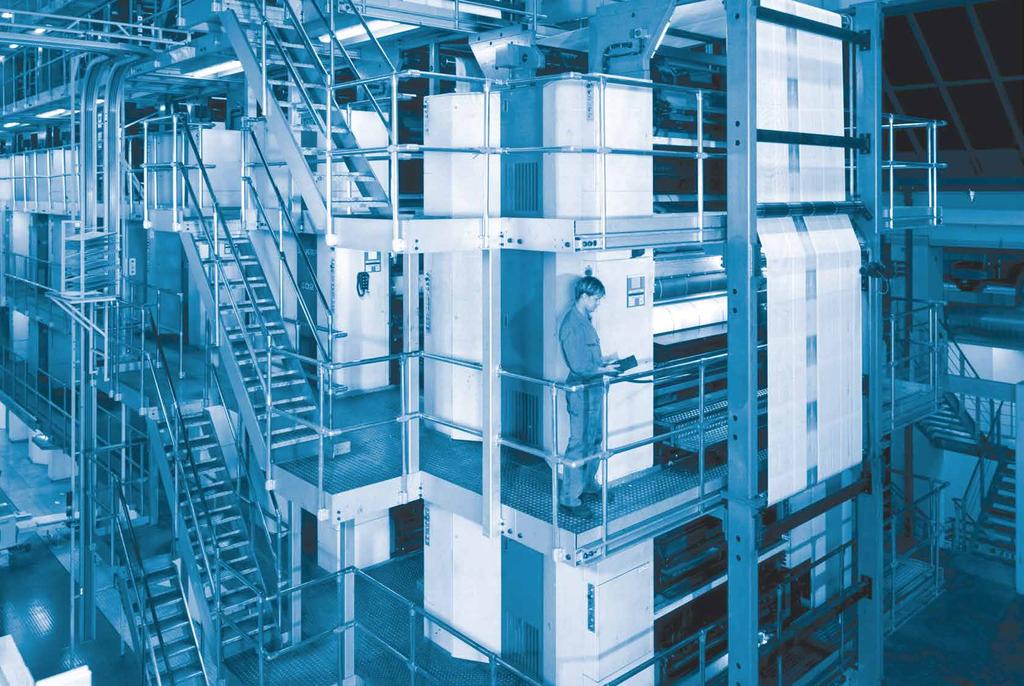

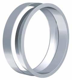
57 RfN 8006 ungeschlitzt solid RfN 8006 geschlitzt slit 57
58 RINGFEDER Spannelemente Locking Elements Charakteristische Eigenschaften Ideal anpassbar in Bezug auf konstruktive Erfordernisse und Gegebenheiten, durch Anzahl der einzusetzenden, nicht selbstzentrierenden Spannelemente, sowie Größe und Anzahl der Spannschrauben. Große übertragbare Umfangskräfte zur Erhöhung der Drehmomente und Axialkräfte können bis zu 4 Spannelemente hintereinander geschaltet werden (siehe Seite 62). Größte Zuverlässigkeit egal ob die Verbindung statisch, schwellend, dynamisch oder stoß artig belastet wird. Einfache Fertigung Wellen und Naben bleiben ungenutet. Außerdem können relativ große Toleranzen zugelassen werden. Leichte Einstellbarkeit Spannelemente arbeiten ohne Formschluss. Die Naben lassen sich daher unter Beachtung der Montage- und Demontageanweisung an jeder beliebigen Stelle und in jeder beliebigen Lage spannen. Absolut spielfrei - keine Gefahr des Ausschlagens. Große Dauerdrehwechselfestigkeit Welle und Nabe sind ungenutet, dadurch geringe Kerbwirkung und optimale Materialausnutzung. Einfache Montage im Vergleich zu Querpresssitzen entfallen Temperaturbehandlungen und Einpassarbeiten. Schrauben sind nur mit handelsüblichen Werkzeugen anzuziehen. Einfache Demontage nach dem Lösen der Spannschrauben sind die Spannelemente RfN 8006 entspannt. Welle und Nabe sind frei beweglich. Verschleiß- und wartungsfrei bei korrekter Auslegung und Anwendung unbegrenzte Lebensdauer. Characteristics 58 Customized application by varying the number of not self-centering Locking Elements, size and quantity of clamping screws, the connection can be adapted to fit most applications concerning surface pressures, materials, hub/shaft dimensions and available mounting space. Transmission of high loads to increase the transmissible torque and axial forces up to 4 Locking Elements can be used in series (see page 62). Maximum reliability no matter whether the connection is subjected to static, pulsating, dynamic or intermittent loads. Simple manufacture shaft and hub are designed without keyway. Apart from this, relatively large tolerances are admissible. Easy adjustability Locking Elements work without positive connection. So they can be adjusted at any place to any position by following the simple installation and removal instructions. Backlash-free the Locking Element connection is a mechanical shrink fit and will not wear or loosen in service provided that the maximum transmissible values for the connection are not exceeded. High fatigue strength under alternating torsional stresses as neither the shaft nor the hub have grooves the notch effect is minimized and a higher polar section modulus is given, enabling the use of smaller diameters. Simple installation in comparison to cross-press fits temperature treatments and fitting are eliminated. Screws have to be tightened with standard tools. Easy removal Locking Elements are self releasing no additional measures or auxiliary equipment is required. Wear and maintenance-free unlimited lifetime if designed and used correctly.
59 Erläuterungen zu Tabellen Explanations to tables Grundabmessungen im ungespannten Zustand Basic dimensions when screws are not tightened d = Innendurchmesser d = Inner diameter D = Außendurchmesser D = Outer diameter L = Einbaulänge maximal L = Overall length L 3 = Innenringbreite L 3 = Width of inner ring A t = Tragende Fläche aus A t = π d L 3 T 100 = Übertragb. Drehmoment bezogen auf p=100 N/mm² F ax100 = Übertragbare Axialkraft bezogen auf p=100 N/mm² X (n) = Mind. Abstand zum Druckflansch bei (n) Spannelement (en). Bei Unterschreitung besteht Gefahr, dass der Druckflansch anliegt, bevor der gewünschte Kraftfluss erreicht wird. A t = Bearing surface A t = π d L 3 T 100 = Transmissible torque based on p=14500 psi F ax100 = Transmissible axial force based on psi X (n) = Min. distance to thrust flange for (n) Locking Element(s). Any reduction of this value could cause that the required transmission value is not achieved. F O F A = Spannkraft zur Spielüberbrückung bei Ausschöpfung der Fertigungstoleranzen - entfällt bei geschlitzten Ausführungen = Erforderliche Spannkraft zur Erzeugung einer Wellenpressung von 100 N/mm 2 F O F A = Clamping force for gap filling to establish manufacturing tolerances - not for slit version = Needed clamping force to get a shaft pressure of psi d 1 = Durchmesser Distanzbuchse innen d 1 = Diameter spacer sleeve inside D 1 = Durchmesser Distanzbuchse außen D 1 = Diameter spacer sleeve outside T max = Max. übertragbares Drehmoment T max = Max. transmissible torque Gw = Gewicht Gw = Weight 59

60 RINGFEDER Spannelemente Locking Elements RfN 8006 X ungeschlitzt solid L L 3 d D D1 d1 d D RINGFEDER Spannelement RfN 8006 Einbausituation RINGFEDER Locking Element RfN 8006 Location RINGFEDER Spannelemente RfN 8006 Maßzeichnung RINGFEDER Locking Elements RfN 8006 Dimensions geschlitzt slit Keilriemenscheibe / V-belt pulley 60
61 Abmessungen Spannelement Spannkraft Übertragbare Drehmomente Spannelemente Durchmesser Distanzbuchse Locking Element dimensions Clamping force oder Axialkräfte Locking Elements Diameter spacer sleeve Transmissible torques innen außen or axial forces inside outside d x D L L 3 A t F 0 F A T 100 F ax100 x Gw d S1 D S1 T max mm mm mm 2 kn Nm N mm kg mm Nm *6 x 9 4,5 3,7 69-3,7 2, ,0015 6,1 8,9 7,8 *7 x 10 4,5 3,7 80-4,4 3, ,0014 7,1 9,9 10 *8 x 11 4,5 3, , ,0015 8,1 10, x 12 4,5 3, ,6 5,7 5, ,0017 9,1 11,9 8,7 10 x 13 4,5 3, , , ,1 12, x 14 4,5 3, ,5 6, ,002 11,1 13, x 15 4,5 3, ,9 7, , ,1 14, x 16 4,5 3, ,4 8, , ,1 15, x 18 6,3 5, ,2 12, , ,1 17, x 19 6,3 5, ,7 13, , ,1 18, x 20 6,3 5, ,1 14, , ,1 19, x 21 6,3 5, ,5 15, , ,1 20, x 22 6,3 5, ,1 16, , ,1 21, x 24 6,3 5, ,6 17, , ,2 23, x 25 6,3 5, , , ,2 24, x 26 6,3 5, ,0 19, , ,2 25, x 28 6,3 5, ,3 21, , ,2 27, x 30 6,3 5, ,9 22, ,01 25,2 29, x 32 6,3 5, ,4 25, ,009 28,2 31, x 35 6,3 5, , ,012 30,2 34, x 36 6,3 5, ,8 28, ,01 32,2 35, x ,1 35, ,02 35,2 39, x ,6 36, ,02 36,2 41, x ,0 38, ,02 38,2 43, x , , ,02 40,2 44, x , , ,03 42,2 47, x , , ,05 45,2 51, x , , ,05 48,2 54, x , , ,05 50,2 56, x , , ,05 55,2 61, x , , ,07 56,2 63, x , , ,07 60,2 67, x , , ,08 63,2 70, x , , ,08 65,2 72, x , , ,11 70,3 78, x , , ,11 71,3 79, x , , ,12 75,3 83, x , ,12 80,3 90, x , ,2 85,3 95, x , ,2 90,3 100, x , ,22 95,3 105, x , , ,4 100,3 113, x , , ,4 110,3 123, x , , ,5 120,3 133, x , , ,85 130,4 147, x , , ,91 140,4 157, x , , ,97 150,4 167, x , , ,02 160,4 177, x , ,5 170,5 190, x , ,6 180,5 200, x , ,7 190,5 210, x , , ,3 200,6 223, x , , ,5 210,6 233, x , , ,5 220,6 243, x , , ,4 230,6 256, x , , ,5 240,6 266, x , ,7 250,8 279, Erläuterungen zu Tabellen: Seite 59 Explanations to tables: Page 59 * Serienmäßig geschlitzt. Bei Spannelementen in geschlitzter Ausführung entfällt in der Berechnung F O * Generally slit. At Locking Elements in slit version F O is eliminated in the calculation. Fortsetzung s. nächste Seite To continue see next page RfN

62 RINGFEDER Spannelemente Locking Elements RfN 8006 Schrauben-Berechnung Schrauben-Tabelle Die von RINGFEDER Spannelementen übertragbaren Dreh momente und Flächenpressungen sind der wirksamen Spannkraft F A direkt proportional. Als Spannmittel werden üblicherweise Schrauben verwendet. Entsprechend der erforderlichen Spannkraft kann die Auswahl nach Schraubenqualität, -größe und -anzahl gemäß untenstehender Tabelle erfolgen. Locking screw calculation Locking screw table The torque transmission capacity of a RINGFEDER Locking Element connection is directly proportional to the effective clamping force F A. As clamping elements normally locking srews are used which act on the Locking Elements via a thrust flange. According to the required tension force, the selection according to screw quality, size and quantity can be done according to the chart below. Regelgewinde 1), metrisch / Regular thread 1), metric d G T A F V T A F V T A F V M 4 2, , , M 5 6, , M M M M M M M M M M M Spannelement-Einbau / Mounting of Locking Element Die Werte für T und F ax, gelten für geölt eingebaute Spannelemente. / The values for T and F ax, apply to Locking Elements installed in oiled condition. Oberflächen / Surface finishes Für Welle und Nabenbohrung / For shafts and hub bores R a 1 µm Erforderliche Schraubenspannkraft bei ungeschlitzten Spannelementen: F A = F A + F 0 bei geschlitzten Spannelementen: F A = F A Required screw tension force for Locking Elements solid: F A = F A + F 0 for Locking Elements slit: F A = F A Bei Hintereinanderschaltung von n-spannelementen gilt zur Erhöhung von T und F ax : Where n-locking Elements are used one behind the other (series), the following applies to the increase in T und F ax : T n = T 1 m und / and F axn = F ax1 m Unter Beibehaltung der Werte für T und F ax können bei Hintereinanderschaltung F A und p reduziert werden. Hier gilt: Retaining the values for T and F ax it is possible to reduce F A and p when using elements in series: F A n = F A /m und / and P N = p/m Bei 2 / 3 / 4 Spannelementen ist m = 1,555 / 1,86 / 2,03 With 2 / 3 / 4 Locking Elements, m = / 1.86 / 2.03 d Welle / Shaft Bohrung / Bore bis/up to 38 h6 H7 über/above 38 h8 H8 Empfohlene Passungen Kundenwelle und Nabe. Bitte nehmen Sie Rücksprache mit unserer technischen Abteilung. Recommended fits for customer shaft and hub. Please contact our technical department. M ) T A = Anziehdrehmoment (Nm) 1) T A = tightening torque (N m ) F V = Vorspannkraft (N) F V = initial clamping force (N) (Schrauben geölt, µ ges = 0,14) (screws oiled, µ total = 0,14) 62
63 Abmessungen Spannelement Spannkraft Übertragbare Drehmomente Spannelemente Durchmesser Distanzbuchse Locking Element dimensions Clamping force oder Axialkräfte Locking Elements Diameter spacer sleeve Transmissible torques innen außen or axial forces inside outside d x D L L 3 A t F 0 F A T 100 F ax100 x Gw d S1 D S1 T max mm mm mm 2 kn Nm N mm kg mm Nm 260 x ,8 260,8 289, x ,9 270,8 299, x ,3 280,8 312, x ,5 290,8 322, x ,7 300,8 332, x , x , x , x , x , x , x , x , x , x , x , x , x , x , x , x , x , x , x , x , x , x , x , x , x , x , x , x , x , x , x , x , x , x , x , Erläuterungen zu Tabellen: Seite 59 Explanations to tables: Page 59 Weitere Größen auf Anfrage More sizes on request Bestellbeispiel Ordering example: RfN 8006 ungeschlitzt/solid Baureihe / Series d D RfN Bestellbeispiel Ordering example: RfN 8006 geschlitzt/slit Baureihe / Series d D Weitere Angaben / Further details RfN G (= geschlitzt / slit) Rundlauf Concentricity Die relativ schmalen Spannelemente RINGFEDER RfN 8006 dienen in erster Linie der Übertragung großer Drehmomente und Axialkräfte. Sie sind nicht selbstzentrierend. Die Rund lauf ge nauig keit der verspannten Naben ist somit von der Zentrierung und der Sorgfalt der Montage abhängig. Spann ele mente RfN 8006 können im Rahmen ihrer Her stellungs genauigkeit zentrieren, wenn sie absolut planparallel zusammengedrückt werden. The relatively narrow RINGFEDER RfN 8006 Locking Elements mainly serve the purpose of transmitting large torques and axial forces. They are not self-centering. The concentricity accuracy of the clamped hub therefore depends on the centering and care of the installation. Locking Elements RfN 8006 can centre themselves within the framework of their production accuracy if they are absolutely plane-parallel when pressed together. RfN
64 RINGFEDER Rostfreie Produkte Stainless Steel Products ROSTFREI STAINLESS STEEL 64


65 Spannsätze Locking Assemblies Spannelemente Locking Elements RfN 7012 rostfrei stainless steel RfN 8006 ungeschlitzt solid rostfrei stainless steel RfN rostfrei stainless steel RfN 8006 geschlitzt slit rostfrei stainless steel RfN 7061 rostfrei stainless steel RfN 7110 rostfrei stainless steel 65
66 RINGFEDER Rostfreie Produkte Stainless Steel Products Charakteristische Eigenschaften Kostengünstige Fertigung größtmögliche Toleranzen und einfache Drehbearbeitung garantieren kostengünstige Fertigung. Einfache Montage es sind nur wenige Schrauben anzuziehen, Ausrichtung zwischen Nabe und Welle winkelgenau in jeder Position möglich, Einpassarbeiten entfallen ganz. Einfache Demontage RINGFEDER Spannsätze verfügen über Abdrückgewinde, daher keine zusätzlichen Hilfsmittel erforderlich, Baureihe RfN 7012 ist sogar selbstlösend (keine Abdrückgewinde). Große Dauerdrehwechselfestigkeit Welle und Nabe sind ungenutet, dadurch keine Schwächung dieser Bauteile. Welle und Nabe können deutlich kleiner ausgeführt werden (leichte, kosten- und platzsparende Konstruktion möglich). Keine Gefahr des Ausschlagens RINGFEDER Spannsätze sind absolut spielfrei. Wirkung wie Überlastsicherung nach dem Überschreiten des eingestellten Kraftschlusses rutschen die Spannsätze durch. Wertvolle Maschinenteile werden geschützt. Die Spannsätze unterliegen hierbei aber den gleichen Gesetzen, wie jede andere Reibschlussverbindung auch - als Rutschkupplung nicht geeignet. Absolut wartungsfrei keine Folgekosten. Characteristics Inexpensive manufacture the large tolerances that are possible and the simple turning process guarantee inexpensive manufacture. Simple installation only a few screws need to be tightened, alignment to precise angles between the hub and shaft is possible in any position, no fitting at assembly required. Simple dismantling RINGFEDER Locking Assemblies are fitted with threaded extraction holes, so that no additional auxiliary equipment is necessary, series RfN 7012 is self-releasing. Large constant reverse-torsion fatigue strength shaft and hub are ungrooved, so that there is no weakening of these components. Shaft and hub can be designed to be considerably smaller (light, cost and space-saving design possible). No danger of deflection RINGFEDER Locking Assemblies are absolutely backlashfree. Effect similar to overload protection after the set frictional connection force has been exceeded the Locking Assemblies simply slide. Valuable machine parts are protected. The Locking Assemblies are subject to the same laws as any other connection with force transmission by friction - not suitable as sliding clutch. Completely maintenance-free no follow-up costs. 66
67 Erläuterungen zu Tabellen Explanations to tables Grundabmessungen im ungespannten Zustand Basic dimensions when screws are not tightened d = Innendurchmesser d = Inner diameter D = Außendurchmesser D = Outer diameter D B1 = Außendurchmesser Bund D B1 = Collar outer diameter L = Einbaulänge maximal L = Overall length L 1 = Einbaulänge mind. ohne Schrauben L 1 = Overall length without screws L 3 = Innenringbreite L 3 = Width of inner ring L 4 = Einbaulänge bis Bund L 4 = Installation length up to collar T = Übertragbares Drehmoment bei angegebenem T A T = Transmissible torque at given T A F ax = Übertragbare Axialkraft F ax = Transmissible axial force p W = Flächenpressung auf der Welle bei angegebenen T A p W = Surface pressure on shaft at given T A p N = Flächenpressung auf der Nabe bei angegebenen T A p N = Surface pressure on hub at given T A n Sc = Anzahl der Spannschrauben n Sc = Quantity of locking screws D G = Gewinde D G = Thread T A = Vorgegebenes Anzugsmoment der Spannschrauben T A = Max. tightened torque of the locking screws D N min = Min. Nabenaußendurchmesser abhängig von der angegebenen Nabenstreckgrenze (Rp 0,2 ) D N min = Min. hub outer diameter depending of the given hub yield point (Rp 0,2 ) T max = Maximal übertragbares Drehmoment T max = Maximum transmissible torque Gw = Gewicht Gw = Weight ROSTFREI STAINLESS STEEL 67
68 RINGFEDER Spannsätze Locking Assemblies RfN 7012 rostfrei stainless steel Charakteristische Eigenschaften Characteristics ROSTFREI STAINLESS STEEL Schmalste Bauform, besonders für Anwendungen bei engen Platzverhältnissen geeignet. Der nicht selbstzentrierende Spannsatz RfN 7012 rostfrei gleicht kleine Toleranzschwankungen aus und kompensiert geringe Montagefehler. Große übertragbare Kräfte und Momente es können mehrere Spannsätze RfN 7012 rostfrei hintereinander angeordnet werden. Die übertragbaren Drehmomente und Axialkräfte addieren sich - bitte diesbezüglich Rücksprache mit unseren technischen Fachleuten nehmen. Einfache Montage im Vergleich zu Querpresssitzen entfallen Temperaturbehandlungen und Einpassarbeiten. Spannsätze RfN 7012 rostfrei können große Passungsspiele überbrücken. Geringe Schmutzempfindlichkeit während des Anziehens der Spannschrauben pressen sich die Funktionsflächen fest gegeneinander. Schmutz und Feuchtigkeit können daher nicht an die Funktionsflächen vordringen. Verschleißfreiheit der Spannsatz RfN 7012 rostfrei arbeitet ohne bewegte Teile auf Welle und Nabe, hierdurch werden Verschleiß und Spiel zuverlässig vermieden. Er kann daher mehrmalig ge- und entspannt werden. Slimmest design, especially suitable for applications where space is limited. The not self-centering Locking Assembly RfN 7012 stainless compensates small tolerance deviations and compensates small mounting errors. Large transmittable forces and moments several Locking Assemblies RfN 7012 stainless can be placed one behind the other. The transmissible torque and axial forces are added - please take in this respect consulting with our technical experts. Easy installation in comparison to crosspress fits temperature treatments and fitting are eliminated. Locking Assemblies RfN 7012 stainless steel can cover a big fitting clearance. Low risk to contamination during tightening process the functional surfaces of the device and connection are pressed together generating a surface pressure that does not allow the ingress of contamination. Adjustable transmission values the locking screw torque can be changed giving a corresponding change in transmission values. RfN 7012 stainless Locking Assemblies can be tightened and released repeatedly. Beispielanwendungen: Kettenräder, Hebel, Riemenscheiben, Aufsteckgetriebe, Band trommeln, Laufräder, Seilscheiben Example applications: Chain wheels, levers, pulleys, slip-on gear mechanisms, belt drums, running wheels, cable sheaves L L 1 L 3 d D Spannsatz / Locking Assembly RfN 7012 rostfrei / stainless steel Maßzeichnung / Dimensions 68
69 Abmessungen Spannsatz Übertragbare Drehmomente Flächenpressung Hochfeste Sonderschrauben D N min Locking Assembly dimensions oder Axialkräfte Surface pressure High-strength special screws bei / at Bestellbeispiel Ordering example: RfN 7012 Transmissible torques Welle Nabe ISO 4762 Rp 0,2 or axial forces Shaft Hub d x D L L 1 L 3 T F ax p W p N n Sc D G T A Gw [N/mm 2 ] T max mm mm Nm kn N/mm 2 Nm kg mm Nm 19 x 47 27, M 6 x , x 47 27, M 6 x , x 47 27, M 6 x , x 50 27, M 6 x , x 50 27, M 6 x , x 55 27, M 6 x , x 55 27, M 6 x , x 60 27, M 6 x , x 60 27, M 6 x , x 65 27, M 6 x , x 65 27, M 6 x , x 75 33, M 8 x , x 75 33, M 8 x , x 80 33, M 8 x , x 80 33, M 8 x , x 85 33, M 8 x , x 90 33, M 8 x , x 95 33, M 8 x , x , M 10 x , x , M 10 x , x , M 10 x , x , M 10 x , x , M 10 x , x , M 10 x , x M 12 x , x M 12 x , x M 12 x , x M 12 x , x M 12 x , x M 12 x , Baureihe / Series d D Weitere Angaben / Further details RfN SST (=rostfrei / stainless steel) Erläuterungen zu Tabellen: Seite 67 Explanations to tables: Page 67 Weitere Größen auf Anfrage More sizes on request Spannsatz-Einbau Mounting of Locking Assembly Die Spannsätze werden leicht geölt und einbaufertig angeliefert. Die Werte für T, F ax, p W und p N gelten für Spann sätze im An liefe rungszustand. / The Locking Assemblies are supplied slightly oiled and ready-to-use. The values for T, F ax, p W and p N apply to Locking Assemblies in delivery condition. Oberflächen Surface finishes Für Welle und Nabenbohrung / For shafts and hub bores R a = 3,2 µm Toleranzen Tolerances Wir empfehlen folgende Einbautoleranzen We recommend the following mounting tolerances Welle Shaft: k9-h9; Nabe Hub: N9-H9 Max. zulässig: Welle: k11-h11; Nabe: N11-H11 Max. permissible: Shaft: k11-h11; Hub: N11-H11 Um übermäßige Verformungen der relativ dickwandigen Druck ringe zu vermeiden, sollte der Spannsatz möglichst sym metrisch zwischen Welle und Nabenbohrung angeordnet werden. Ist also die Welle kleiner als Nennmaß d, so sollte die Bohrung um den gleichen Betrag größer sein als Nennmaß D und umgekehrt. Die Rundlaufqualität wird bestimmt durch die direkte Zentrierung zwischen Welle und Nabe. / To avoid excessive deformations of the relatively thickwalled thrust rings, the Locking Assembly should be located as symmetrically as possible between shaft and hub bore. If the shaft is smaller than nominal d, the bore should exceed nominal D to the same extent and vice versa. The concentricity quality is determined by the direct centering between shaft and hub. Anordnung mehrerer Spannsätze RfN 7012 rostfrei Arrangement of several Locking Assemblies RfN 7012 stainless steel Sind mehrere Spannsätze einzubauen, können die Übertragungswerte aus der Tabelle addiert werden, wenn die Spannsätze innerhalb einer Distanz von 4 L angeordnet werden. / If several Locking Assemblies are to be installed the transmission values of the table can be added when the Locking Assemblies are located within a distance of 4 L. Veränderung der Schraubenanziehdrehmomente Change of screw tightening torques Die Spannsätze sind generell mit Schrauben der Qualität A2-70 ausgerüstet. Eine Redu zierung durch vermindertes Anziehen der Schrau ben ist möglich. (Bitte mit unseren Spezialisten Rück sprache nehmen). The Locking Assemblies are generally equipped with A2-70 grade screws. A reduction of the screw tightening torque is possible. (Please contact our specialists for assistance). Hilfsgewinde Auxiliary threads Zur Erleichterung der Demontage sind in den vorderen Druckringen Hilfsgewinde vorhanden. To facilitate removal, the front thrust rings have auxiliary threads. Berechnung Nabenaußendurchmesser Calculation hub outer diameter Faktor C = 0,6 siehe Seite 83 / Factor C=6 see page 83 RfN
70 RINGFEDER Spannsätze Locking Assemblies RfN rostfrei stainless steel Charakteristische Eigenschaften Characteristics Ausgezeichneter Rundlauf und sehr gute Demontierbarkeit mit diesen selbstzentrierenden Spannsätzen wird ein besonders guter Rundlauf zwischen den verspannten Teilen erreicht. Der Flansch ist an der kritischen Stelle verstärkt, dies verhindert ein Durchbiegen und Abheben des Innenringes während der Montage. Dadurch ist eine gute Demontierbarkeit sichergestellt. Höhere Drehzahl die Spannsätze bleiben formgenau während der Montage und sind besser für hohe Drehzahlen geeignet. Excellent concentricity and very easy to dismantle these self-centering Locking Assemblies provide particularly good concentricity between the clamped parts. The flange is reinforced at the critical point, preventing bending or lifting of the inner ring during assembly and thereby ensuring easy dismantling. High rotation speed the dimensional accuracy allows their use in applications with higher rotational speeds. ROSTFREI STAINLESS STEEL Hohe Radiallasten aufgrund der hohen Materialfestigkeit ist der Spannsatz für hohe Radiallasten besonders geeignet. Axiale Nabenfixierung zusätzlich wird durch den hochgezogenen Flansch die Nabe bei der Montage axial fixiert und außerdem eine hohe Planlaufgenauigkeit erzielt. High radial loads the material strength makes them especially suitable for applications with high radial loads. Axial hub positioning the increased outer diameter of the flange prevents the axial movement of the hub during assembly, and improves the run-out ability of the locking assembly. Beispielanwendungen: Kettenräder, Hebel, Riemenscheiben, Aufsteckgetriebe, Band trommeln, Laufräder, Seilscheiben Example applications: Chain wheels, levers, pulleys, slip-on gear mechanisms, belt drums, running wheels, cable sheaves L L 1 L 4 L 3 d D1 D Spannsatz / Locking Assembly RfN rostfrei / stainless steel Maßzeichnung / Dimensions 70
71 Abmessungen Spannsatz Übertragbare Drehmomente Flächenpressung Hochfeste Sonderschrauben Locking Assembly dimensions oder Axialkräfte Surface pressure High-strength special screws Transmissible torques Welle Nabe ISO 4762 or axial forces Shaft Hub d x D L L 1 L 3 L 4 D B1 T F ax p W p N n Sc D G T A Gw T max mm mm Nm kn N/mm 2 Nm kg Nm 19 x ,7 25, M 6 x , x ,7 25, M 6 x , x ,7 25, M 6 x , x ,7 25, M 6 x , x ,7 25, M 6 x , x ,7 25, M 6 x , x ,7 25, M 6 x , x ,7 25, M 6 x , x ,7 25, M 6 x , x ,7 25, M 6 x , x ,7 25, M 6 x , x ,3 30, M 8 x , x ,3 30, M 8 x , x ,3 30, M 8 x , x ,3 30, M 8 x , x ,3 30, M 8 x , x ,3 30, M 8 x , x ,3 30, M 8 x , x ,4 40, M 10 x , x ,4 40, M 10 x , x ,4 40, M 10 x , x ,4 40, M 10 x , x ,4 40, M 10 x , x ,4 40, M 10 x , x ,8 47, M 10 x , x ,8 47, M 10 x x ,8 47, M 10 x , x ,4 52, M 12 x , x ,4 52, M 12 x , x ,4 52, M 12 x , Bestellbeispiel Ordering example: RfN Baureihe / Series d D Weitere Angaben / Further details RfN SST (=rostfrei / stainless steel) Erläuterungen zu Tabellen: Seite 67 Explanations to tables: Page 67 Weitere Größen auf Anfrage More sizes on request Spannsatz-Einbau Mounting of Locking Assembly Die Spannsätze werden leicht geölt und einbaufertig angeliefert. Die Werte für T, Fax, p W und p N gelten für Spann sätze im An lieferungszustand. The Locking Assemblies are supplied slightly oiled and readyto-use. The values for T, F ax, p W and p N apply to Locking Assemblies installed in the delivery condition. Oberflächen Surface finishes Für Welle und Nabenbohrung / For shafts and hub bores Ra = 1,6 µm Toleranzen Tolerances Wir empfehlen folgende Einbautoleranzen We recommend the following mounting tolerances Welle Shaft: h8; Nabe Hub: H8 Anordnung mehrerer Spannsätze RfN rostfrei Arrangement of several Locking Assemblies RfN stainless steel Anordnung nur von 2 Seiten möglich. Bei Verwendung mehrerer Spannsätze zur Steigerung der Übertragungswerte, ist der Verspannungssystematik Rechnung zu tragen. Arrangement only possible from 2 sides. If several Locking Assemblies are used to increase the transmission values the clamping systematization has to be considered. Veränderung der Schraubenanziehdrehmomente Change of screw tightening torques Eine Veränderung der in der Tabelle angegebenen TA-Werte ist nicht zulässig. A change of the TA-values given in the above table is not admissible. RfN

72 RINGFEDER Spannsätze Locking Assemblies RfN 7061 rostfrei stainless steel L N 2 L - L 1 DN Charakteristische Eigenschaften Selbstzentrierende 2-teilige Spannsätze für mittlere Dreh momente. Bei der Montage erfolgt eine geringe Axial verschiebung der Nabe vom Schrau ben kopf weg. Aufgrund der geringen Schraubenzahl sind Kostenein spar ungen bei der Montage gewährleistet. Zur Demontage sind nur wenige Abdrückschrauben nötig. Spannsatz / Locking Assembly RfN 7061 Einbausituation / Location Nabenberechnung siehe Seite / Calculation of hubs see on page (Berechnung für andere Nabenformen in unserem Berechnungsprogramm möglich Calculation possible for other hub forms in our calculation program) L L 1 D Characteristics Self-centering 2-piece Locking Assem blies for medium torques. During mount ing, minor axial displacement of the hub occurs in opposite direction of the screw head. Due to the small number of screws, cost savings during mounting are ensured. For disassembly only few release screws are required. Spannsatz RfN 7061 Maßzeichnung / Locking Assembly RfN 7061 Dimensions d ROSTFREI STAINLESS STEEL 72
73 Abmessungen Spannsatz Übertragbare Drehmomente Flächenpressung Hochfeste Sonderschrauben Locking Assembly dimensions oder Axialkräfte Surface pressure High-strength special screws Transmissible torques Welle Nabe ISO 4762 or axial forces Shaft Hub d x D L L 1 T F ax p W p N n Sc D G * T A Gw mm mm Nm kn N/mm 2 Nm kg 6 x 16 13, M 2,5 5 0, x 16 13, M 2,5 5 0,012 7 x 17 13, M 2,5 5 0,013 8 x 18 13, M 2,5 5 0,015 9 x 20 15, M 2,5 5 0, x 20 15, M 2,5 5 0, x 20 15, M 2,5 5 0, x 22 15, M 2,5 5 0, x 22 15, M 2,5 5 0, x M , x M , x M , x M , x M , x M , x M ,1 22 x M ,11 24 x M ,2 25 x M , x M ,19 28 x M ,2 30 x M ,27 32 x M ,25 35 x M ,36 38 x M ,43 40 x M ,4 42 x M ,75 45 x M ,7 48 x M ,8 50 x M ,76 *HINWEIS! Größe M 2,5 Spannschraube ISO A2-70 REMARK! Size M 2,5 locking screws ISO A2-70. Bestellbeispiel Ordering example: RfN 7061 Baureihe / Series d D Weitere Angaben / Further details RfN SST (=rostfrei / stainless steel) Erläuterungen zu Tabellen: Seite 67 Explanations to tables: Page 67 Weitere Größen auf Anfrage More sizes on request Oberflächen Surface finishes Für Welle und Nabenbohr. /For shafts and hub bores R a = 3,2 µm Toleranzen Tolerances Wir empfehlen folgende Einbautoleranzen We recommend the following mounting tolerances Welle Shaft: h8; Nabe Hub: H8 RfN

74 RINGFEDER Spannsätze Locking Assemblies RfN 7110 rostfrei stainless steel L L 1 L 4 d D D1 Spannsatz RfN 7110 Maßzeichnung / Locking Assembly RfN 7110 Dimensions Charakteristische Eigenschaften Besonders kompakter selbstzentrierender Spannsatz ohne Axialver schiebung. Da die Spannschrauben außer halb der eigentlichen Spannstelle liegen und die Pressungen relativ gering sind kann die Nabe ökonomisch klein gestaltet werden. Characteristics Specially small dimensioned self-centering Locking Assembly without axial displacement. As the locking srews are located out of the actual clamping area and the pressures are relatively low, the hub can be designed economically small. ROSTFREI STAINLESS STEEL 74
75 Abmessungen Spannsatz Übertragbare Drehmomente Flächenpressung Hochfeste Sonderschrauben Locking Assembly dimensions oder Axialkräfte Surface pressure High-strength special screws Transmissible torques Welle Nabe ISO 4762 or axial forces Shaft Hub d x D L L 1 L 4 D B1 T F ax p W p N n Sc D G T A Gw mm mm mm Nm kn N/mm 2 Nm kg 8 x M ,06 9 x M ,07 10 x M ,06 11 x M ,07 12 x M ,07 13 x M ,12 14 x M ,12 15 x M ,21 16 x M ,2 17 x M ,22 18 x M ,24 19 x M ,25 20 x M ,25 22 x M ,34 24 x M ,36 25 x M ,35 28 x M ,43 30 x M ,43 32 x M ,46 35 x M ,52 38 x M ,61 40 x M ,67 42 x M ,74 45 x M ,12 48 x M ,14 50 x M ,3 Bestellbeispiel Ordering example: RfN 7110 Baureihe / Series d D Weitere Angaben / Further details RfN SST (= rostfrei / stainless steel) Erläuterungen zu Tabellen: Seite 67 Explanations to tables: Page 67 Weitere Größen auf Anfrage More sizes on request Oberflächen Surface finishes Für Wellenbohrungen / For shaft bores Ra = 3,2 µm Für Nabenbohrungen / For hub bores Ra = 1,6 µm Toleranzen Tolerances Wir empfehlen folgende Einbautoleranzen We recommend the following mounting tolerances Welle Shaft: h8; Nabe Hub: H8 RfN
76 RINGFEDER Spannelemente Locking Elements RfN 8006 rostfrei stainless steel X L L 3 d D D1 d1 d D RINGFEDER nicht selbstzentrierendes Spannelement RfN 8006 rostfrei RINGFEDER not self-centering Locking Element RfN 8006 stainless steel Einbausituation Location ungeschlitzt solid RINGFEDER nicht selbstzentrierendes Spannelement RfN 8006 rostfrei RINGFEDER not self-centering Locking Element RfN 8006 stainless steel Maßzeichnung Dimensions geschlitzt slit ROSTFREI STAINLESS STEEL Keilriemenscheibe / V-belt pulley 76
77 Abmessungen Spannelement Spannkraft Übertragbare Drehmomente Spannelemente Durchmesser Distanzbuchse Locking Assembly dimensions Clamping force oder Axialkräfte Locking Elements Diameter spacer sleeve Transmissible torques innen außen or axial forces inside outside d x D L L 3 A t F 0 F A T 100 F ax100 x Gw d S1 D S1 T max mm mm mm 2 kn Nm N mm kg mm Nm *6 x 9 4,5 3,7 69-3, ,0015 6,1 8,9 6,2 *7 x 10 4,5 3,7 80-4,4 2, ,0014 7,1 9,9 8,2 *8 x 11 4,5 3, , ,0015 8,1 10,9 10,5 9 x 12 4,5 3, ,6 5,7 4, ,0017 9,1 11, x 13 4,5 3, ,3 5, , ,1 12,9 9,7 11 x 14 4,5 3, ,5 6,9 6, ,002 11,1 13,9 11,7 12 x 15 4,5 3, ,9 7,5 8, , ,1 14, x 16 4,5 3, ,4 8,2 9, , ,1 15, x 18 6,3 5, ,2 12,6 16, , ,1 17, x 19 6,3 5, ,7 13,5 18, , ,1 18, x 20 6,3 5, ,1 14,4 20, , ,1 19, x 21 6,3 5, ,5 15,3 23, , ,1 20, x 22 6,3 5, ,1 16,2 26, , ,1 21, x 24 6,3 5, ,6 17,1 28, , ,2 23, x 25 6,3 5, , , , ,2 24, x 26 6,3 5, ,0 19,8 38, , ,2 25, x 28 6,3 5, ,3 21,6 46, , ,2 27, x 30 6,3 5, ,9 22,5 49, ,01 25,2 29, x 32 6,3 5, ,4 25,2 62, ,009 28,2 31, x 35 6,3 5, , , ,012 30,2 34, x 36 6,3 5, ,8 28,8 81, ,01 32,2 35, x ,1 35,6 110, ,02 35,2 39, x ,6 36,6 117, ,02 36,2 41, x ,0 38,7 130, ,02 38,2 43, x , , , ,02 40,2 44, x , , , ,03 42,2 47, x , , , ,05 45,2 51, x , , , ,05 48,2 54, x , , ,05 50,2 56, x , , ,05 55,2 61, x , , ,07 56,2 63, x , , ,07 60,2 67, x , , ,08 63,2 70, x , , ,08 65,2 72, x , , ,11 70,3 78, x , , ,11 71,3 79, x , , ,12 75,3 83, x , ,12 80,3 90, x , ,2 85,3 95, x , ,2 90,3 100, x , ,22 95,3 105, x , , ,4 100,3 113, x , , ,4 110,3 123, x , , ,5 120,3 133, x , , ,85 130,4 147, x , , ,91 140,4 157, x , , ,97 150,4 167, Erläuterungen zu den Tabellen siehe Seite 59 und 62 Explanations to tables on page 59 and 62 * Serienmäßig geschlitzt. Bei Spannelementen in geschlitzter Ausführung entfällt in der Berechnung F O * Generally slit. At Locking Elements in slit version F O is eliminated in the calculation. Weitere Größen auf Anfrage More sizes on request Bestellbeispiel Ordering example: RfN 8006 ungeschlitzt/solid Bestellbeispiel Ordering example: RfN 8006 geschlitzt/slit Baureihe / Series d D Weitere Aufgaben / Further details RfN SST (=rostfrei / stainless steel) Baureihe / Series d D Weitere Angaben / Further details RfN SST-G (=rostfrei, geschlitzt / stainless steel, slit) RfN
78 Sonderlösungen Special Solutions 78

79 Spannsätze Locking Assemblies RfN RfN


80 Sonderlösungen Special Solutions Sonderlösung Spannsätze Wo der Einsatz von Standard-Spannsätzen nicht ausreicht, entwickeln wir spezielle, auf die jeweiligen Kundenanforderungen optimierte Lösungen und bieten so den optimalen Nutzen. Anwendungen die bisher nicht möglich waren, können so in vielen Fällen trotzdem realisiert werden. RfN

81 Sonderlösungen Special Solutions Special Solution Locking Assemblies Where the use of standard Locking Assemblies is not sufficient we develop special solutions optimised to specific customer requirements so that the parts are ideal for the specific application. In this way it is possible to make use of applications which previously were not possible. RfN
82 Naben- und Wellenberechnung Calculation of hub and shaft Berechnungen Für die Abschätzung der in der Nabe und Hohlwelle auftretenden Tangential-(Zug-)Spannungen leisten die Gleichungen für dickwandige Hohlzylinder gute Dienste. Die exakte Ermittlung der wahren Spannungen und Verformungen (Aufweitung, Einschnürung) ist infolge der streuenden Reibwerte und unterschiedlichen Formen von Nabe und Hohlwelle recht schwierig. Konstruktionen, bei denen Spannsätze unter oder über Lagern anzuordnen wären, sind daher möglichst zu vermeiden oder aber näher zu untersuchen (z. B. durch Probeverspannung). Nabenberechnungen Hub calculation Calculation Equations for thick-walled cylinders give good service in the estimation of the tangential (tension) stresses occurring in the hub and hollow shaft. Exact determination of the true stresses and deformations (expanding, contraction) is very difficult in view of the wide scatter of the coefficients of friction and because of the differing hub and hollow shaft configurations. Constructions in which Locking Assemblies are intended to be arranged under or above bearings should therefore be avoided as far as possible, or be more closely investigated (e. g. test clamping). Wellenberechnungen Hollow shaft calculation 1) p N p d W D 1) a W = d d B 2) 3) a N = D N D tin = p N (a N 2+1) a N 2-1 ; L N = L 3 2) 3) C 3 tiw 2 p W a 2 W +1 taw p W C 3 a _ 2 W 1 a W 2 a W 2 _ 1 4) 5) 6) 7) 8) 2 p tan = N ; LN = L 3 a N 2-1 ; L N > 2L tin = C. 3 p. N (a N 2+1) 3 a N 2-1 tan = C. 3 p N. 2 a N 2-1 D N D N D. D. ; L N > 2L 3 R p0,2n R p0,2n +C 3. pn _ C3. pn R p0,2n a) + C 3. pn R p0,2n _ +2D C3. G b) pn 4) 5) 6) 7) 8) d B d B d B d R p0,2w p W d d d B tiw E W p W d (m 1) E W m R p0,2w _ 2 p W C 3 R p0,2w R p0,2w 2 p W C 3 R p0,2w a) 2D G b) c) c) 9) 10) D N p N zul. D N tan E N R p0,2n C 3 D _ 2 N D 2 D 2 N + D 2 c) a) 9) p zul. R p0,2w 1 C 3 2 d B d 2 a) L N L D N 2 p N Rp 0,2 N Streckgrenzen/ Yield strength Rp 0,2 W p W d B 2 D N D d d B L 3 82
83 Naben- und Wellenberechnung Calculation of hub and shaft Schnittdarstellungen Sectional view C 3 = 0,6 L N 2. L 3 C 3 = 0,6 n = 1 C 3 = 0,8 L N L. (1 + n) L N L. (1 + n) C 3 = 0,8 n 2 C 3 = 0,8 n 1 LN = L 3 L N L. n DG DG C 3 = 1 C 3 = 1 n = 1 C 3 = 1 n 1 Erläuterungen a) Nabenquerschnitt über dem Spannsatz ungeschwächt. C3 = 0,6 bei einem Spannsatz und L N 2 L 3 C3 = 0,8 bei zwei und mehr Spannsätzen und L N L (1 + n); n = Anzahl der Spannsätze C3 = 1 bei einem oder mehreren Spannsätzen und L N = L 3 bzw. L N = L n b) Wenn Bohrungen oder Gewinde ( DG ) in der Nabe. C3 = 0,8 wenn L N 2 L 3 bzw. L N L (1 + n) C3 = 1 wenn L N = L 3 bzw. L N = L n c) Näherungswert. Große Streuungen möglich, da vom tatsächlichen Reibwert und von Nabenform abhängig. Explanation a) Cross section of the hub above the Locking Assembly, unweakened. C3 = 0,6 for one Locking Assembly and L N 2 L 3 C3 = 0,8 for two ore more Locking Assemblies and L N L (1 + n); n = number of Locking Assemblies C3 = 1 for one or more Locking Assemblies and L N = L 3 or L N = L n b) If bores or threads ( DG ) in the hub. C3 = 0,8 if L N 2 L 3 or L N L (1 + n) C3 = 1 if L N = L 3 or L N = L n c) Approximated value. A higher scatter range is possible, as the value depends on the actual coefficient of friction and the shape of the hub. 83
84 RINGFEDER Spannsätze Locking Assemblies RfN 7012 Entspannt der hintere Druckring nicht selbsttätig, so werden die Schrauben um einige Gänge herausgedreht. Nach einigen leichten Schlägen gegen die Schraubenköpfe springt der Druckring nach. If the rear thrust ring is not automatically released, the screws have to be turned out by a few threads. Light tapping against the screw heads causes the rear thrust ring to spring backwards. Das Entspannen eines evtl. klemmenden vorderen Druckringes erfolgt in ähnlicher Weise. Nach dem Entfernen der Schrauben mit den Unterlegscheiben sind die Demontage-Hilfsgewinde des vorderen Druckringes zugänglich. Über entsprechende Schrauben kann der vordere Druckring gelöst sowie ein tief in einer Nabenbohrung angeordneter Spannsatz herausgezogen werden. Should the front thrust ring jam, it is released in a similar way. The marked screws (washer) are removed from the auxiliary threads of the front thrust ring. The front thrust ring can be released and a Locking Assembly which is located deeply in the hub bore can be removed by corresponding screws. 6 dd d G 1 Spannsatz RfN Bezeichnung der Einzelteile. Locking Assembly RfN Part description. 1 Hinterer Druckring 2 Außenring, geschlitzt 3 Innenring, geschlitzt 4 Vorderer Druckring 5 Unterlegscheibe 6 Spannschraube d D Hilfsgewinde d G Gewinde 1 Rear thrust ring 2 Outer ring, slit 3 Inner ring, slit 4 Front thrust ring 5 Washer 6 Locking screw d D Auxiliary thread d G Thread 84
85 Montage- und Demontageanweisungen Spannsatz RfN 7012, RfN 7012 rostfrei Montage Installation and removal instructions Locking Assembly RfN 7012, RfN 7012 stainless steel Installation Die Kraftübertragung erfolgt durch Pressung und Reibung zwischen den Funktionsflächen. Auf kontrolliertes Anziehen der Spannschrauben und Beschaffenheit der Kontaktflächen ist daher besonders zu achten. 1. Sämtliche Kontaktflächen, einschließlich Gewinde und Kopfauflage der Spannschrauben müssen sauber und mit einem Ölfilm versehen sein (kein Molybdän-Disulfid verwenden). Welle, Nabe und Spannsätze in diesem Zustand montieren. 2. Spannschrauben leicht anziehen und Nabe ausrichten. 3. Schrauben in zwei bis drei Stufen gleichmäßig und überkreuz auf das angegebene Anziehdrehmoment T A anziehen. 4. Kontrolle des Anziehdrehmomentes der Schrauben in der Reihenfolge ihrer Anordnung. Erst wenn sich keine Schraube mehr anziehen läßt, ist die Montage beendet. Demontage Since the force is transmitted by contact pressure and friction between functional surfaces, condition of contact surfaces and proper tightening of the locking screws are of great importance. 1. All contact surfaces, including screw threads and screw head bearing surfaces, must be clean and slightly oiled (Do not use Molybdenum Disulphide!). In this condition, the shaft, hub and Locking Assemblies are to be assembled. 2. Tighten locking screws lightly and align hub. 3. Tighten screws evenly in diametrically opposite sequence and do this in two or three stages up to the indicated tightening torque T A. 4. Re-check tightening torque by applying it to all screws all the way around. When no screw will turn anymore, the assembly is completed. Removal Spannsätze RINGFEDER RfN 7012 sind nicht selbsthemmend. Der Konus der einzelnen Ringe wurde so gewählt, dass keine Selbsthemmung eintreten kann. Nach dem Lösen der letzten Schraube ist die Verbindung in der Regel frei. Die unter den Schrauben liegenden Unterlegscheiben schützen die Demontage-Hilfsgewinde vor Beschädigung. Sind größere Kräfte zum Herausnehmen des bereits gelösten Spannsatzes erforderlich (wenn der Spannsatz z.b. gegen das Gewicht einer schweren Nabe verschoben werden soll), so dürfen bei Verwendung einer Demontage-Hilfsvorrichtung die Schrauben nur gelockert, aber keinesfalls zu weit herausgedreht werden. Bei Beachtung dieses Hinweises ist gegen die Verwendung von Demontage-Hilfsvorrichtungen nichts einzuwenden, solange die Kräfte gering bleiben. Die Demontage-Hilfsgewinde besitzen nur ca. 3-5 tragende Gewindegänge und sind nicht durchgeschnitten. Es sind also keine Bohrungen für Abdrückschrauben. Verschmutzte, unbeschädigte Spannsätze sind vor der erneuten Verwendung zu zerlegen und zu reinigen. Locking Assemblies RINGFEDER RfN 7012 are not selflocking. The taper of the individual rings is such that the inner and outer rings spring apart. After loosening the last screw the connection is usually disengaged. The washers under the screws protect the auxiliary (removal) threads against damage. If relatively great forces are needed to extract a Locking Assembly that has already been loosened (e. g. if the Locking Assembly has to be pushed against the weight of a heavy boss or hub), any type of removal device may be used, but the screws must only be slackened and not screwed out too far. As long as this instruction is followed, there is no objection against the use of a removal device, provided the forces applied are kept low. The auxiliary threads have only about 3-5 effective courses and are not cut right through. Do not use these holes for jack screws. Dismount and clean dirty undamaged Locking Assemblies before re-use. RfN
86 RINGFEDER Spannsätze Locking Assemblies RfN 7013 Montage eines Spannsatzes RfN Mounting of a Locking Assembly RfN Montage eines Spannsatzes RfN Mounting of a Locking Assembly RfN Demontage eines Spannsatzes RfN Removing of a Locking Assembly RfN Demontage eines Spannsatzes RfN Removing of a Locking Assembly RfN
87 Montage- und Demontageanweisungen Spannsatz RfN , RfN Installation and removal instructions Locking Assembly RfN , RfN Montage Installation Die Kraftübertragung erfolgt durch Pressung und Reibung zwischen den Funktionsflächen. Auf kontrolliertes Anziehen der Spannschrauben und Beschaffenheit der Kontaktflächen ist daher besonders zu achten. 1. Sämtliche Kontaktflächen, einschließlich Gewinde und Kopfauflage der Spannschrauben müssen sauber und mit einem Ölfilm versehen sein (kein Molybdän-Disulfid verwenden). Welle, Nabe und Spannsätze in diesem Zustand montieren. 2. Spannschrauben leicht anziehen und Nabe ausrichten. 3. Schrauben in zwei bis drei Stufen gleichmäßig und überkreuz auf das angegebene Anziehdrehmoment anziehen. 4. Kontrolle des Anziehdrehmomentes der Schrauben in der Reihenfolge ihrer Anordnung. Erst wenn alle Schrauben das angegebene Anziehmoment T A erreicht haben, ist die Montage beendet. Since the force is transmitted by contact pressure and friction between functional surfaces, condition of contact surfaces and proper tightening of the locking screws are of great importance. 1. All contact surfaces, including screw threads and screw head bearing surfaces, must be clean and slightly oiled (Do not use Molybdenum Disulphide!). In this condition, the shaft, hub and Locking Assemblies are to be assembled. 2. Tighten locking screws lightly and align hub. 3. Tighten screws evenly in diametrically opposite sequence and do this in two or three stages up to the indicated tightening torque T A. 4. Re-check tightening torque by applying it to all screws all the way around. If all screws have reached the max. tightening torque T A, the assembly is completed. Demontage Die Demontage der Spannsätze RfN 7013 erfolgt in der Reihenfolge: 1. Sämtliche Schrauben um mehrere Gänge herausdrehen. 2. Die neben den Abdrückbohrungen angeordneten Schrauben entfernen und in diese Bohrungen einschrauben. Hierdurch wird der Außenring zwangsläufig vom Innenring geschoben. Die Verbindung ist gelöst. 3. Nabenkörper und Spannsätze von der Welle abschieben oder abziehen. Die Abdrückschrauben sollten erst entfernt werden, wenn der Spannsatz vollkommen demontiert ist. Verschmutzte, unbeschädigte Spannsätze sind vor der erneuten Verwendung zu zerlegen und zu reinigen. Removal The Locking Assemblies RfN 7013 are to be removed in the following sequence: 1. Loosen all screws by a few turns. 2. Remove the screws adjacent to each threaded bore and screw them into these bores pressing off the outer ring. The connection is then released. 3. The connection can be either readjusted or disassembled. Remove the jack screws only after the Locking Assembly has been taken out of the hub. Dismount and clean dirty undamaged Locking Assemblies before re-use. RfN
88 RINGFEDER Spannsätze Locking Assemblies RfN dg Spannsatz im ungespannten Zustand gezeichnet Locking Assembly not tightened 1 Hinterer Druckring 2 Außenring, geschlitzt 3 Innenring, geschlitzt 4 Vorderer Druckring 5 Spannschraube d G Gewinde 1 Rear thrust ring 2 Outer ring, slit 3 Inner ring, slit 4 Front thrust ring 5 Locking screw d G Thread Spannsatz mit Schraube in der Abdrückbohrung Locking Assembly with a screw in one of the release threads 88
89 Montage- und Demontageanweisungen Spannsatz RfN 7014 Montage Installation and removal instructions Locking Assembly RfN 7014 Installation Die Kraftübertragung erfolgt durch Pressung und Reibung zwischen den Funktionsflächen. Auf kontrolliertes Anziehen der Spannschrauben und Beschaffenheit der Kontaktflächen ist daher besonders zu achten. 1. Bei original verpackten Spannsätzen sind vor dem Einbau die als Transportsicherung in den Schlitzen des Innenund Außenringes angeordneten Bleche zu entfernen. 2. Sämtliche Kontaktflächen, einschließlich Gewinde und Kopfauflage der Spannschrauben müssen sauber und mit einem Ölfilm versehen sein (kein Molybdän-Disulfid verwenden). Welle, Nabe und Spannsätze in diesem Zustand montieren. 3. Spannschrauben leicht anziehen und Nabe ausrichten. 4. Schrauben in zwei bis drei Stufen gleichmäßig und überkreuz auf das angegebene Anziehdrehmoment anziehen. 5. Kontrolle des Anziehdrehmomentes der Schrauben in der Reihenfolge ihrer Anordnung. Erst wenn alle Schrauben das angegebene Anziehmoment T A erreicht haben, ist die Montage beendet. Since the force is transmitted by contact pressure and friction between the functional surfaces, the condition of the contact surfaces and correct tightening of the locking screws are of great importance. 1. When originally packed, Locking Assemblies are fitted with small metal packing pieces located in the slits of the inner and outer rings. These are for shipping purposes only and MUST be removed prior to installation. 2. All contact surfaces, including screw threads and screw head bearing surfaces, must be clean and slightly oiled (Do not use Molybdenum Disulphide!). In this condition, the shaft, hub and Locking Assemblies are to be assembled. 3. Tighten locking screws lightly and align hub. 4. Tighten screws evenly in diametrically opposite sequence and do this in two or three stages up to the indicated final tightening torque T A. 5. Re-check tightening torque by applying it to all the screws. If all screws have reached the max. tightening torque T A, the assembly is completed. Demontage Die Demontage der Spannsätze RfN 7014 erfolgt in der Reihenfolge: 1. Sämtliche Schrauben um einige Gänge herausdrehen. 2. Die neben den Abdrückbohrungen angeordneten Schrauben entfernen und in diese Bohrungen einschrauben. Durch Abstützung des hinteren Druckringes am Wellenoder Nabenbund werden die Konen voneinandergeschoben, die Verbindung ist gelöst. 3. Nabenkörper und Spannsätze von der Welle abschieben oder abziehen. Die Abdrückschrauben sollten erst entfernt werden, wenn der Spannsatz vollkommen demontiert ist. Verschmutzte, unbeschädigte Spannsätze sind vor der erneuten Verwendung zu zerlegen und zu reinigen. Beachten Sie, dass die Abdrückgewinde des vorderen Druckringes gegenüber ungebohrten Flächen des hinteren Druckringes positioniert werden müssen. Diese Gewinde werden zur Demontage benötigt. Removal The Locking Assemblies RfN 7014 are to be removed as follows: 1. Loosen all screws by a few threads. 2. Remove the screws adjacent to each threaded release hole and screw them into these holes. Since the rear thrust ring rests against either shaft or hub shoulder, the jack screws will automatically push apart both tapers, thus releasing the connection. 3. The connection can be either readjusted or disassembled. Remove the jack screws only after the Locking Assembly has been taken out of the hub. Used Locking Assemblies have to be replaced and slightly oiled prior to reinstallation. Note that the release threads of the front thrust ring have to be positioned opposite to undrilled spaces of the rear thrust ring. These threads are used for removal. RfN
90 RINGFEDER Spannsätze Locking Assemblies RfN 7015/7515 Zeichnungen zu RfN 7015 Figures for RfN dg Abbildung 1: Spannsatz RfN Bezeichnung der Einzelteile. Figure 1: Locking Assembly RfN Part description. 1 Hinterer Druckring 2 Außenring, geschlitzt 3 Innenring, geschlitzt 4 Vorderer Druckring 5 Spannschraube d G Gewinde 1 Rear thrust ring 2 Outer ring, slit 3 Inner ring, slit 4 Front thrust ring 5 Locking screw d G Thread Abbildung 2: Demontage vorderer Druckring Figure 2: Removal front thrust ring Abbildung 3: Demontage hinterer Druckring Figure 3: Removal rear thrust ring 90 Abbildungen zu RfN 7515 siehe Seite 92 Figures for 7515 see page 92
91 Montage- und Demontageanweisungen Spannsatz RfN , , 7515 Montage Installation and removal instructions Locking Assembly RfN , , 7515 Installation Die Kraftübertragung erfolgt durch Pressung und Reibung zwischen den Funktionsflächen. Auf kontrolliertes Anziehen der Spannschrauben und Beschaffenheit der Kontaktflächen (s. Punkt 1) ist daher besonders zu achten. 1. Sämtliche Kontaktflächen, einschließlich Gewinde und Kopfauflage der Spannschrauben müssen sauber und mit einem Ölfilm versehen sein (kein Molybdän-Disulfid verwenden). Welle, Nabe und Spannsätze in diesem Zustand montieren. 1.1 Es empfiehlt sich, die aus Transportgründen tief eingeschraubten Spannschrauben soweit herauszudrehen, dass nur noch wenige Gänge im hinteren Druckring verbleiben. 1.2 Bei größeren Spannsätzen ist es vorteilhaft, einige Spannschrauben gemäß Abb. 2 in den vorderen Druckring einzuschrauben, um das Einbauen des Spannsatzes durch Druck auf diese Schrauben zu vereinfachen. 2. Bei eingebautem Spannsatz nun alle Spannschrauben (eingesetzt in den Gewindebohrungen des hinteren Druckringes) leicht anziehen und die Nabe ausrichten. 3. Schrauben in zwei bis drei Stufen gleichmäßig und überkreuz auf das angegebene Anziehdrehmoment (T A ) anziehen. 4. Kontrolle des Anziehdrehmomentes der Schrauben in der Reihenfolge ihrer Anordnung. Erst wenn alle Schrauben das angegebene Anziehmoment T A erreicht haben, ist die Montage beendet. Gebrauchte Spannsätze vor dem Einbau reinigen, leicht einölen und nach Abb. 1 zusammensetzen. Beim Zusammenbau ist darauf zu achten, dass allen Gewindebohrungen des hinteren Druckringes (1) Durchgangsbohrungen des Steges des Innenringes (3) und des vorderen Druckringes (4) zugeordnet sind. Den Abdrückgewinden im vorderen Druckring sind bohrungsfreie Stellen im Innenring und den Abdrückgewinden im Innenring bohrungsfreie Stellen im hinteren Druckring zuzuordnen, s. Abb. 1. Since the force is transmitted by contact pressure and friction between functional surfaces, condition of contact surfaces and proper tightening of the locking screws are of great importance (see point 1). 1. All contact surfaces, including screw threads and screw head bearing surfaces, must be clean and slightly oiled (Do not use Molybdenum Disulphide!). In this condition, the shaft, hub and Locking Assemblies are to be assembled. 1.1 Unscrew all locking screws far enough so that only few threads are engaged in the rear thrust ring. For shipping purposes, these screws have been screwed in quite deep. 1.2 With larger Locking Assemblies, it is advantageous to insert several locking screws into the corresponding threads of the front thrust ring according to Fig. 2 and push against them. 2. After the Locking Assembly is placed in position, slightly tighten all locking screws (screwed into the rear thrust ring) and make final alignment and adjustment of the connection. 3. Tighten screws evenly in diametrically opposite sequence and do this in two or three steps up to the indicated tightening torque T A. 4. Re-check tightening torque by applying it to all screws all the way around. If all screws have reached the max. tightening torque T A, the assembly is completed. Used Locking Assemblies have to be cleaned and slightly oiled prior to installation and reassembled according to Fig. 1 When reassembling, it is important to make sure that all threaded holes of the rear thrust ring (1) are in line with the holes in web of inner ring (3) and front thrust ring (4). Threaded removal holes in front thrust ring must be located opposite blanc spaces in web of inner ring, and the threaded removal holes in web of inner ring must be located opposite blanc spaces of rear thrust ring, see Fig. 1. RfN 7015/
92 RINGFEDER Spannsätze Locking Assemblies RfN 7015/7515 Zeichnungen zu RfN 7515 Figures for RfN d G Abbildung 1: Spannsatz RfN Bezeichnung der Einzelteile. Figure 1: Locking Assembly RfN Part description. 1 Hinterer Druckring 2 Außenring 3 Vorderer Druckring 4 Spannschraube d G Gewinde 1 Rear thrust ring 2 Outer ring 3 Front thrust ring 4 Locking screw d G Thread Abbildung 2: Demontage vorderer Druckring Figure 2: Removal front thrust ring Abbildung 3: Demontage hinterer Druckring Figure 3: Removal rear thrust ring 92 Abbildungen zu RfN 7015 siehe Seite 90 Figures for 7015 see page 90
93 Montage- und Demontageanweisungen Spannsatz RfN , , 7515 Demontage Die Demontage der Spannsätze RfN 7015 erfolgt in der Reihenfolge: 1. Sämtliche Schrauben um mehrere Gänge herausdrehen. 2. Die neben den Abdrückbohrungen angeordneten Schrauben entfernen und in diese Bohrungen einschrauben. 2.1 Der vordere Druckring wird dann dadurch gelöst, dass er durch in seine Abdrückgewinde eingeschraubte Schrauben, die sich am Steg des Innenringes abstützen, aus seiner Position geschoben wird (Abb. 2). 2.2 Der hintere Druckring wird in entsprechender Weise gemäß Abb. 3 gelöst. 3. Nabenkörper und Spannsätze von der Welle abschieben oder abziehen. Die Abdrückschrauben sollten erst entfernt werden, wenn der Spannsatz vollkommen demontiert ist. Verschmutzte, unbeschädigte Spannsätze sind vor der erneuten Verwendung zu zerlegen und zu reinigen. Installation and removal instructions Locking Assembly RfN , , 7515 Removal The Locking Assemblies RfN 7015 are to be removed as follows: 1. Loosen all screws by a few turns. 2. Remove the screws adjacent to each threaded bore and screw them into these bores. 2.1 The front thrust ring is released by having the jack screws pressed against the web of the inner ring (see Fig. 2). 2.2 The rear thrust ring is released by having the jack screws inserted in the threaded bore of the inner ring web and thus pushing it out (Fig. 3). 3. Pull or push hub and Locking Assemblies off the shaft. The jack screws should be removed only after the Locking Assembly has been taken out of the hub. Disassemble and clean dirty, undamaged Locking Assemblies before re-use. RfN 7015/
94 RINGFEDER Spannsätze Locking Assemblies RfN 7061 rostfrei stainless steel Abbildung 1: Montage eines Spannsatz RfN 7061 Figure 1: Mounting of a Locking Assembly RfN 7061 Abbildung 2: Demontage eines Spannsatz RfN 7061 Figure 2: Removal of a Locking Assembly RfN
95 Montage- und Demontageanweisungen Spannsatz RfN 7061rostfrei Montage Installation and removal instructions Locking Assembly RfN 7061 stainless steel Installation Die Kraftübertragung erfolgt durch Pressung und Reibung zwischen den Funktionsflächen. Auf kontrolliertes Anziehen der Spannschrauben und Beschaffenheit der Kontaktflächen (siehe Punkt 1) ist daher besonders zu achten. 1. Sämtliche Kontaktflächen, einschließlich Gewinde und Kopfauflage der Spannschrauben müssen sauber und mit einem leichten Ölfilm versehen sein (Kein Molybdän-Disulfid verwenden). Welle, Nabe und Spannsätze in diesem Zustand montieren. 2. Spannschrauben leicht anziehen und die Einheit den Erfordernissen entsprechend ausrichten. 3. Schrauben in zwei bis drei Stufen gleichmäßig und überkreuz auf das angegebene Anziehdrehmoment anziehen. 4. Kontrolle des Anziehdrehmomentes der Schrauben in der Reihenfolge ihrer Anordnung. Erst wenn alle Schrauben das angegebene Anziehmoment T A erreicht haben, ist die Montage beendet. Since the force is transmitted by contact pressure and friction between functional surfaces, the condition of the contact surfaces and proper tightening of the locking screws are of great importance (see point 1). 1. All contact surfaces, including screw threads and screw head bearing surfaces, must be clean and slightly oiled (Do not use Molybdenum Disulphide!). In this condition, the shaft, hub and Locking Assemblies are to be assembled. 2. Tighten locking screws lightly and align hub. 3. Tighten screws evenly in diametrically opposite sequence and do so in two or three steps up to the indicated tightening torque. 4. Recheck tightening torque by applying it to all screws all the way around. If all screws have reached the max. tightening torque T A, the assembly is completed. Demontage Die Demontage der Spannsätze RfN 7061 erfolgt in der Reihenfolge: 1. Sämtliche Schrauben um einige Gewindegänge herausdrehen. 2. Einige Schrauben ganz herausdrehen und in die Gewindebohrungen des Flansches einschrauben. 3. Die zum Abdrücken umgesetzten Schrauben in mehreren Stufen, in Reihenfolge, bis zum Lösen der Verbindung anziehen. Hierbei sollte mit dem Abdrücken möglichst nicht in direkter Schlitznähe begonnen werden. Der Außenring wird hierdurch zwangsläufig vom Innenring geschoben. Die Verbindung ist gelöst. 4. Nabenkörper und Spannsätze von der Welle abschieben oder abziehen. Verschmutzte, unbeschädigte Spannsätze sind vor der erneuten Verwendung zu zerlegen, zu reinigen und entsprechend Punkt 1der Montage leicht einzuölen. Removal The Locking Assemblies RfN 7061 are to be removed in the following sequence: 1. Loosen all screws by a few turns. 2. Remove the screws adjacent to each threaded jacking hole and screw them into these bores. 3. Tighten the jacking screws, starting with the positions furthest away from the slit first, in several steps until the connection is released. 4. The connection can then either be readjusted or disassembled. Remove the jacking screws only after the Locking Assembly has been removed from the hub. Dismount and clean dirty undamaged Locking Assemblies before re-use and slightly oil them as described in point 1 of the mounting instructions. RfN
96 RINGFEDER Spannsätze Locking Assemblies RfN 7110 rostfrei stainless steel Diese Verbindung ist im montierten Zustand dargestellt. Die Keilriemenscheibe stützt sich während der Montage über die Distanzbuchse am Innenring des Spannsatzes RfN 7110 ab und bleibt so ebenfalls axial eindeutig positioniert. This connection is shown in mounted condition. During mounting, the V-belt pulley is supported by the spacer bushing at the inner ring of the Locking Assembly RfN 7110 and thus also stays axially clearly positioned. Befestigung eines Kegelrades mit einem Spannsatz RfN Während der Montage bleibt das Kegelrad in seiner axialen Position fixiert. Bevel gear mounted with one Locking Assembly RfN During mounting the axial position of the bevel gear remains unchanged. 96
")
97 Montage- und Demontageanweisungen Spannsatz RfN 7110 rostfrei Montage Installation and removal instructions Locking Assembly RfN 7110 stainless steel Installation Die Kraftübertragung erfolgt durch Pressung und Reibung zwischen den Funktionsflächen. Auf kontrolliertes Anziehen der Spannschrauben und Beschaffenheit der Kontaktflächen (siehe Punkt 1) ist daher besonders zu achten. 1. Sämtliche Kontaktflächen, einschließlich Gewinde und Kopfauflage der Spannschrauben müssen sauber und mit einem leichten Ölfilm versehen sein. (Kein Molybdän-Disulfid verwenden). Welle, Nabe und Spannsätze in diesem Zustand montieren. 2. Spannschrauben leicht anziehen und die Einheit den Erfordernissen entsprechend ausrichten. 3. Schrauben in zwei bis drei Stufen gleichmäßig und überkreuz auf das angegebene Anziehdrehmoment anziehen. 4. Kontrolle des Anziehdrehmomentes der Schrauben in der Reihenfolge ihrer Anordnung. Erst wenn alle Schrauben das angegebene Anziehmoment T A erreicht haben, ist die Montage beendet. Since the force is transmitted by contact pressure and friction between functional surfaces, the condition of the contact surfaces and proper tightening of the locking screws are of great importance (see point 1). 1. All contact surfaces, including screw threads and screw head bearing surfaces, must be clean and slightly oiled (Do not use Molybdenum Disulphide!). In this condition, the shaft, hub and Locking Assemblies are to be assembled. 2. Tighten locking screws lightly and align hub. 3. Tighten screws evenly in diametrically opposite sequence and do so in two or three steps up to the indicated tightening torque. 4. Recheck tightening torque by applying it to all screws all the way around. If all screws have reached the max. tightening torque T A, the assembly is completed. Demontage Die Demontage der Spannsätze RfN 7110 erfolgt in der Reihenfolge: 1. Sämtliche Schrauben um einige Gewindegänge herausdrehen. 2. Einige Schrauben ganz herausdrehen und in die Gewindebohrungen des Flansches einschrauben. 3. Die zum Abdrücken umgesetzten Schrauben in mehreren Stufen, in Reihenfolge, bis zum Lösen der Verbindung anziehen. Hierbei sollte mit dem Abdrücken möglichst nicht in direkter Schlitznähe begonnen werden. Der Außenring wird hierdurch zwangsläufig vom Innenring geschoben. Die Verbindung ist gelöst. 4. Nabenkörper und Spannsätze von der Welle abschieben oder abziehen. Verschmutzte, unbeschädigte Spannsätze sind vor der erneuten Verwendung zu zerlegen, zu reinigen und entsprechend Punkt 1 der Montage leicht einzuölen. Removal The Locking Assemblies RfN 7110 are to be removed in the following sequence: 1. Loosen all screws by a few turns. 2. Remove the screws adjacent to each threaded jacking hole and screw them into these bores. 3. Tighten the jacking screws, starting with the positions furthest away from the slit first, in several steps until the connection is released. 4. The connection can then either be readjusted or disassembled. Remove the jacking screws only after the Locking Assembly has been removed from the hub. Dismount and clean dirty undamaged Locking Assemblies before re-use and slightly oil them as described in point 1 of the mounting instructions. RfN

98 RINGFEDER Spannelemente Locking Elements RfN 8006 Innenring Inner ring Außenring Outer ring Spannelement RfN 8006 Ansicht und Schnitt Locking Element RfN 8006 View and section x A B D C Anziehen der Spannschrauben und Abstandsmaß x Tightening of the locking screws and distance x 98
99 Montage- und Demontageanweisungen Installation and removal instructions Die Kraftübertragung erfolgt durch Pressung und Reibung zwischen den Funktionsflächen. Auf kontrolliertes Anziehen der Spannschrauben und korrekte Beschaffenheit der Kontaktfläche (s. Punkt 1) ist daher besonders zu achten. 1. Sämtliche Kontaktflächen, einschließlich Gewinde und Kopf auflage der Spannschrauben müssen sauber und mit einem Öl film versehen sein. 2. Montage der Einzelteile in der Reihenfolge A = Nabe Spannelementringe (B) entsprechend Montagezeichnung einsetzen (beide Teile müssen sich leicht montieren lassen und dürfen keinesfalls klemmen). C = Druckflansch (Distanzbuchse, wenn erforderlich) oder Druckflansch mit Bund einsetzen. Auf leichte Verschiebbarkeit beider Teile ist zu achten. D = Spannschrauben Die Spannschrauben sind vor dem Einbau gut zu ölen. Dies gilt besonders für die Schraubenkopfauflage. ACHTUNG: Nicht mit Molybdän-Disulfid arbeiten! Die Schrauben müssen sich leicht und genügend tief eindrehen lassen. Keine Federringe oder Fächerscheiben verwenden! 3. Spannschrauben leicht anziehen und Nabe ausrichten. 4. Schrauben in mehreren Stufen gleichmäßig und überkreuz auf das angegebene Anziehdrehmoment T A mittels Drehmomentschlüssel anziehen. 5. Kontrolle des Anziehdrehmomentes der Schrauben in der Reihen folge ihrer Anordung. Erst wenn alle Schrauben das angegebene Anziehmoment T A erreicht haben, ist die Montage beendet. 6. Kontrolle des Abstandsmaßes x: Der Druckflansch darf die Stirnseite der Nabe in keinem Fall berühren. Der verbleibende Spalt sollte möglichst gleichmäßig sein. Demontage 1. Sämtliche Schrauben in mehreren Umläufen der Reihe nach lösen. 2. Flansch herausnehmen. 3. Spannelemente herausnehmen die Spannelemente entspannen sich nach Lösen der Schrauben selbständig. Falls nicht, genügen leichte Schläge, um den Lösevorgang einzuleiten. Since the force is transmitted by contact pressure and friction between functional surfaces, condition of contact surfaces and proper tightening of the locking screws are of great importance (see point 1). 1. All contact surfaces, including screw threads and screw head contact surface, must be clean and slightly oiled. 2. Fit the parts in the following order: A = Hub Insert the Locking Element rings (B) according to the assembly drawing (both parts must be easy to install and must not jam under any circumstances). C = Insert compression flange (distance sleeve if necessary) or compression flange with collar. Ensure that both parts are easy to move. D = Locking screws Carefully oil the locking screws before fitting. This applies in particular to the screw head seat. ATTENTION: Do not use Molybdenum Disulphide! The screws must turn easily and to an adequate depth. Do not use spring washers or serrated locking washers. 3. Tighten locking screws lightly and align hub. 4. Tighten screws evenly in diametrically opposite sequence and do this with a torque wrench in several stages up to the indicated tightening torque ( T A ). 5. Recheck tightening torque by applying it to all screws all the way around. If all screw have reached the max. tightening torque T A, the assembly is completed. 6. Check distance x: The thrust ring must never contact the face of the hub. The gap between thrust ring and hub face should be as uniform as possible. Removal 1. Loosen all screws one after the other in several steps. 2. Remove the flange. 3. Take out the Locking Elements the Locking Elements release automatically after the screws have been loosened. If not, light tapping is enough to start the releasing process. RfN


100 Online Service Berechnungsprogramm für Spannsätze und Spannelemente Um der komplexen Anforderung bei der richtigen Auslegung und Auswahl der RINGFEDER Produkte unter praxisrelevanten Beanspruchungen zu entsprechen, wurde von der RINGFEDER POWER TRANSMISSION GMBH ein Berechnungsprogramm entwickelt. Interessiert? Besuchen Sie unsere Webseite Calculation program for Locking Assemblies and Locking Elements In order to meet the complex requirements on the correct design and selection of RINGFEDER products under practise-relevant demands, RINGFEDER POWER TRANSMISSION GMBH has developed a calculation program. Interested? Visit our Website at Unsere Website Informationen im schnellen Zugriff. RINGFEDER POWER TRANSMISSION - eine der ersten Adressen, wenn es um antriebs- und dämpfungstechnische Lösungen im Maschinenbau geht. Service und Informationen aus erster Hand finden Sie auf unserer Website. Neben Details zu unserem gesamten Produktportfolio halten wir auf unserer Website zahlreiche Dokumente wie Produktkataloge, Datenblätter und Montageanleitungen für Sie zum Download bereit. Ein Besuch auf bringt Sie auf den neuesten Stand. Our Website Easily accessible information. RINGFEDER POWER TRANSMISSION one of the top addresses for drive and damping technology in mechanical engineering. You can find first-hand service details and information on our website. It contains both details on our entire range of products and numerous documents such as product catalogues, data sheets and assembly instruction for you to download. Visit to get right up to date. 100
101 Fax-Anfrage / Fax Inquiry Für die Auslegung einer RINGFEDER Welle-Nabe-Verbindung To get a design proposal for RINGFEDER shaft-hub-connection RINGFEDER POWER TRANSMISSION GMBH, Groß-Umstadt FAX: +49 (0) Absender Addresser Firma / Company z. Hd. / attn. Abt. / Dept. Adresse / Address Phone Fax Wir bitten um ein Beratungsgespräch. Rufen Sie uns bitte unter / We ask for a consulting discussion. Please call us under zurück / back Um unseren Mitarbeitern die Beratung Ihres Problems zu erleichtern und Irrtümern bzw. Fehlern vorzubeugen, sollte Ihre Anfrage die nachfolgenden Angaben enthalten / To make it easy for our technical staff and to avoid errors or mistakes your inquiry should include the following information: Angaben für den Beratungs-Service Information for technical service Maximal auftretende Belastungen / Expected maximum loads: Max. Drehmoment / Max. torque T max. = Nm Max. Biegemoment / Max. bending moment M bmax. = Nm Max. Axiallast / Max. axial load F ax max. = kn Max. Radiallast / Max. radial load F r max. = kn Dimensionen, Werkstoffe / Dimensions, materials: Durchmesser der Welle / Shaft diameter d w = mm Bei Hohlwelle, Innendurchmesser In case of hollow shaft, internal diameter d B = mm Drehzahl der Welle / Shaft revolution speed n = 1/min Außendurchmesser Nabe / Hub outside diameter D N = mm Nabenbreite / Hub width L N = mm Nabenmaterial bzw. Streckgrenze / Hub material/yield strength R p0,2n = N/mm 2 Wellenmaterial bzw. Streckgrenze / Shaft material/yield strength R p0,2w = N/mm 2 Betriebstemperatur der Verbindung / Temperature of the connection Temp. = C Sonstige Angaben / Additional information: Bitte fügen Sie Ihrer Anfrage eine Zeichnung oder Skizze bei! Please send us a drawing or sketch together with your inquiry! RINGFEDER POWER TRANSMISSION GMBH Werner-Heisenberg-Straße 18 D Groß-Umstadt Postfach / P.O. Box 1163 D Groß-Umstadt Phone: +49 (0) Fax: +49 (0) sales.international@ringfeder.com 101


102 RINGFEDER POWER TRANSMISSION Welle-Nabe- Verbindungen Locking Devices Spannsätze Locking Assemblies Spannsätze für Biegemomente Locking Assemblies for bending loads Spannsätze rostfrei Locking Assemblies Stainless steel Spannelemente Locking Elements Schrumpfscheiben Shrink Discs Schrumpfscheiben rostfrei Shrink Discs Stainless steel Dämpfungstechnik Damping Technology Reibungsfedern Friction Springs DEFORM plus DEFORM plus R Sonderlösungen Special Solutions Spannsätze Locking Assemblies Wellenkupplungen Shaft Couplings Flanschkupplungen Flange Couplings 102


103 Partner for Performance Kupplungen Couplings Drehelastische Kupplungen Torsionally Flexible Couplings Drehelastische Kupplungen Torsionally Flexible Couplings Hochelastische Kupplungen Highly Flexible Couplings Drehstarre Zahnkupplungen Torsionally Rigid Gear Couplings Drehstarre Tonnenkupplung Torsionally Rigid Barrel Coupling Kupplungen mit variabler Steifigkeit Couplings with variable Stiffness Kupplungen Couplings Metallbalgkupplungen Metal Bellows Couplings Elastomerkupplungen Servo-Insert Couplings Sicherheitskupplungen Safety Couplings Zwischenwellen Line Shafts Torsionssteife Lamellenkupplungen Torsionally Rigid Disc Couplings 103


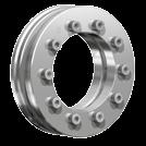

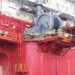
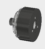


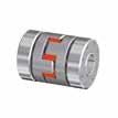

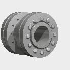


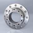


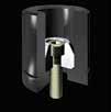


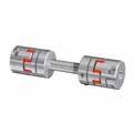
104 RINGFEDER POWER TRANSMISSION GMBH Werner-Heisenberg-Straße 18, D Groß-Umstadt, Germany Phone: +49 (0) Fax: +49 (0) RINGFEDER POWER TRANSMISSION TSCHAN GMBH Zweibrücker Strasse 104, D Neunkirchen, Germany Phone: +49 (0) Fax: +49 (0) RINGFEDER POWER TRANSMISSION USA CORPORATION 165 Carver Avenue, Westwood, NJ 07675, USA Toll Free: Phone: Fax: RINGFEDER POWER TRANSMISSION INDIA PRIVATE LIMITED Plot No. 4, Door No. 220, Mount - Poonamallee Road, Kattupakkam, Chennai , India Phone: +91 (0) Fax: +91 (0) sales.india@ringfeder.com KUNSHAN RINGFEDER POWER TRANSMISSION COMPANY LIMITED No. 10 Dexin Road, Zhangpu Town , Kunshan, China Phone: +86 (0) Fax: +86 (0) sales.china@ringfeder.com RINGFEDER POWER TRANSMISSION
Kostengünstige Fertigung größtmögliche Toleranzen und einfache Drehbearbeitung garantieren kostengünstige Fertigung.
 RINGFEDER Rostfreie Produkte Stainless Products Charakteristische Eigenschaften Kostengünstige Fertigung größtmögliche Toleranzen und einfache Drehbearbeitung garantieren kostengünstige Fertigung. Einfache
RINGFEDER Spannsätze Locking Assemblies RfN 7012
 RINGFEDER Spannsätze Locking Assemblies RfN 7012 Spannsatz / Locking Assembly RfN 7012 Einbausituation / Location L1 L I d D Spannsatz / Locking Assembly RfN 7012 Maßzeichnung / Dimensions Spannsatz /
Spannsätze & Spannelemente Locking Assemblies & Locking Elements
 DE EN 10 2016 Spannsätze & Spannelemente Locking Assemblies & Locking Elements Partner for Performance www.ringfeder.com Mars Rover: Courtesy NASA/ JPL-Caltech Willkommen beim Systemlieferant rund um den
Spannsätze & Spannelemente Locking Assemblies & Locking Elements
 DE EN 03 2013 Spannsätze & Spannelemente Locking Assemblies & Locking Elements Partner for performance www.ringfeder.com Wir sind für Sie da A Global Presence For You Die heutige RINGFEDER POWER TRANS
Locking Assemblies ECOLOC
 Locking Assemblies ECOLOC E EN 03 2013 Anderen vertrauen Sie, bei uns sind Sie sicher! ECOLOC you can trust others you can t be sure! Immer da, wo mit spitzer Feder gerechnet werden muss, bietet RINGFEER
Wir sind für Sie da A global presence for you
 02 Wir sind für Sie da A global presence for you RINGFEDER wurde 1922 in Krefeld Uerdingen als Patentverwertungsgesellschaft für Reibungsfedern gegründet. Seit dem hat sich der Name RINGFEDER zu einem
Spannsätze & Spannelemente Locking Assemblies & Locking Elements
 D GB 12 2008 Spannsätze & Spannelemente Locking Assemblies & Locking Elements Partner for Performance www.ringfeder.com Wir sind für Sie da A Global Presence For You Die heutige RINGFEDER POWER TRANS MISSION
1/2 3/4 5/6 7/8 9/10
 chrumpfscheiben / hrink Discs eite / Page WR 270 39-89000 Nm chrumpfscheibe / hrink Disc eite / Page WR 275 200-3770 Nm 1/2 WR 280 Wellenkupplung / haft Coupling 11 WR 400/410 160-18800 Nm chrumpfscheibe
Baureihe Series PKA/PKB
 Spielfreie Metallbalgkupplungen Backlash-free Metal Bellow Couplings Baureihe Series PKA/PKB DE EN 09 2011 Partner for performance www.gerwah.com Spielfreie Metallbalgkupplung Backlash-free Metal Bellow
RINGFEDER Spannelement RfN 8006 Einbausituation RINGFEDER Locking Element RfN 8006 Location
 RINGFEDER Spannelemente Locking Elements RINGFEDER Spannelement Einbausituation RINGFEDER Locking Element Location ungeschlitzt unslit L I D d RINGFEDER Spannelemente Maßzeichnung RINGFEDER Locking Elements
Drehmomentexplosion in Edelstahl! Torque explosion in stainless steel!
 DE EN 03 2013 Spannsätze und Schrumpfscheiben aus Edelstahl Locking Assemblies and Shrink Discs made of stainless steel NEU NEW Drehmomentexplosion in Edelstahl! Torque explosion in stainless steel! Lieferbar
POSIMIN Drehstarre Kupplungen Torsiononally rigid disc Couplings Accouplements rigides en torsion
 DE EN FR 10 2014 POSIMIN Drehstarre Kupplungen Torsiononally rigid disc Couplings Accouplements rigides en torsion Partner for performance www.ringfeder.com Mars Rover: Courtesey NASA/ JPL Calltech Willkommen
WK RINGFEDER Wellenkupplungen Shaft Couplings. Explanations
 RINGFEDER Wellenkupplungen Shaft Couplings WK 5071 LD LH D d dw Explanations TA = tightening torque per screw (dg) T = transmissible torque Fax = transmissible axial force Further hints, explanations and
Spannsätze - selbstzentrierend Locking Assemblies - Self-centering
 Geringe radiale Einbaumaße Sehr niedrige Flächenpressung Während der Montage erfolgt keine axiale Restricted hub diameter Very low surface pressure Set screws M M F a P W [kg] 6 14 10 18,5 21 24 25 3 x
Dear Colleague, Please give us a call and let us know how we can assist you. We look forward to talking to you soon. Thank you.
 Dear Colleague, Thank you for visiting our website and downloading a product catalog from the R.M. Hoffman Company. We hope this information will be useful to you in solving the application you are working
Flanschkupplungen Flange Couplings RfN 5571 DE EN Partner for performance
 Flanschkupplungen Flange Couplings RfN 5571 DE EN 08 2014 Partner for performance www.ringfeder.com Flanschkupplungen Flange Couplings RINGFEDER RfN 5571 Flanschkupplungen von RINGFEDER sind die bessere
Dear Colleague, Please give us a call and let us know how we can assist you. We look forward to talking to you soon. Thank you.
 Dear Colleague, Thank you for visiting our website and downloading a product catalog from the R.M. Hoffman Company. We hope this information will be useful to you in solving the application you are working
With output shaft, output housing & taper roller bearings. Getriebe mit Abtriebswelle, Kegelrollenlagerung und Gehäuse
 Fine Cyclo - F3C-A With output shaft, output housing & taper roller bearings Getriebe mit Abtriebswelle, Kegelrollenlagerung und Gehäuse Page Seite Type Designation 65 Typenbezeichnung Dimensions 66 Maße
Snap-in switch for switches PSE, MSM and MCS 30
 Product manual Snap-in switch for switches PSE, MSM and MCS 30 CONTENTS 1. PRODUCT DESCRIPTION 2. DATA AND DIMENSIONAL DRAWINGS 2.1. Technical Data 2.2. Dimensions of PSE with a Mounting Diameter 19 mm
1/2 3/4 5/6 7/8 9/10
 chrumpfscheiben - Wellenkupplungen hrink Discs - haft Couplings chrumpfscheiben / hrink Discs eite / WR 270 Page 39-89000 Nm chrumpfscheibe / 1/2 hrink Disc Wellenkupplungen / haft Couplings WR 275 180-4300
KBK Das Unternehmen. KBK The Company
 KBK Das Unternehmen Unser Unternehmen wurde am 02.0.03 gegründet. Die Idee von qualitativ hochwertigen, austauschkompatiblen Produkten zu günstigen Preisen hat uns seitdem einen ständig wachsenden Stamm
RINGFEDER Schrumpfscheiben Shrink Discs RfN 4161
 RINGFEDER Schrumpfscheiben Shrink Discs RfN 4161 Standard Reihe Standard Series d w Schrumpfscheibe RINGFEDER RfN 4161 Einbausituation Shrink Disc RINGFEDER RfN 4161 Location L L 1 I 3 d D Schrumpfscheibe
KBK Das Unternehmen. KBK The Company
 KBK Das Unternehmen Unser Unternehmen wurde am 02.0.03 gegründet. Die Idee von qualitativ hochwertigen, austauschkompatiblen Produkten zu günstigen Preisen hat uns seitdem einen ständig wachsenden Stamm
Sortimentsliste/Product Range Spannsätze Locking Assemblies
 Sortimentsliste/Product Range 2017 Spannsätze Locking Assemblies Ihr Spezialist für innovative Lösungen! Your specialist for innovative solutions! Kompetenz Seit mehr als 25 Jahren Erfahrung im ereich
VERNICKELT NICKEL PLATED
 RINGFEDER Schrumpfscheiben Shrink Discs RfN 4061 Standard Reihe Standard Series Schrumpfscheibe RINGFEDER RfN 4061 Einbausituation Shrink Disc RINGFEDER RfN 4061 Location L 2 L L 1 I 3 d d 1 D d w OPTIONAL
RINGFEDER Spannsätze Locking Assemblies RfN 7015/7515
 RINGFEDER Spannsätze Locking Assemblies RfN 7015/7515 Abbildung 1: Spannsatz RfN 7015. Bezeichnung der Einzelteile. Figure 1: Locking Assembly RfN 7015. Part description. Abbildung 2: Demontage vorderer
RINGFEDER Schrumpfscheiben Shrink Discs RfN 4051
 RINGFEDER Schrumpfscheiben Shrink Discs RfN 4051 Leichte Reihe Light Duty Series d w Schrumpfscheibe RINGFEDER RfN 4051 Einbausituation Shrink Disc RINGFEDER RfN 4051 Location L L 1 L 2 l 3 d d 1 D Schrumpfscheibe
RINGFEDER Schrumpfscheiben Shrink Discs RfN 4073
 RINGFEDER Schrumpfscheiben Shrink Discs RfN 4073 Mini Reihe Mini Series Schrumpfscheibe RINGFEDER RfN 4073 Einbausituation Shrink Disc RINGFEDER RfN 4073 Location L L 1 L 2 I 3 d d 1 D d w Schrumpfscheibe
WK RINGFEDER Wellenkupplungen Shaft Couplings. L total. d w
 RINGFEDER Wellenkupplungen Shaft Couplings L L total D d d w 84 Abmessungen Wellenkupplungen Shaft couplings dimensions Übertragbare Drehmomente oder Axialkräfte Transmissible torques or axial forces Spannschrauben
Flanschversion mit output flange & Kegelrollenlagerung bearings
 Fine Cyclo - F2C-A Speed reducer with Flanschversion mit output flange & integrierter integrated taper roller Kegelrollenlagerung bearings Page Seite Type Designation 51 Typenbezeichnung Dimensions 52
Units HFUS-2UJ. Technische Daten. Technical Data. Abmessungen. Dimensions
 Units HFUS2UJ Technische Daten Technical Data Die HFUS2UJ Unit zeichnet sich neben dem leistungsfähigen KreuzrollenAbtriebslager insbesondere durch ihre Eingangswelle aus. Die in der Unit gelagerte Eingangswelle
Bauform A Bauform B * Bauform A Bauform C. Horizontal Horizontal Vertikal mit Hängefeder Vertikal mit Einlegering
 Beschreibung Schalenkupplungen sind drehstarre Kupplungen und zuverlässige Wellenverbindungen, die Stösse und radiale oder axiale wirkende en ertragen können. Die gekuppelten Wellen müssen genau fluchten.
Modularer Klemmrollenfreilauf GL...F2-D2(D3) Modular freewheel, roller type GL...F2-D2(D3)
 Modular freewheel, roller type GL...F2-D2(D3)") Modularer Klemmrollenfreilauf GL...F2-D2(D3) Modular freewheel, roller type GL...F2-D2(D3) Modell GL...F2-D2(D3) Die GL...F2-D2(D3) Serie ist gekennzeichnet durch Passungen zwischen dem Freilauf GL, dem
Modularer Klemmrollenfreilauf GL...F2-D2(D3) Modular freewheel, roller type GL...F2-D2(D3) Modell GL...F2-D2(D3) Die GL...F2-D2(D3) Serie ist gekennzeichnet durch Passungen zwischen dem Freilauf GL, dem
-0,02,2 E -0,12. p = max. Flächenpressung (N/mm2 )
") 10WR 10WR/I Dichtungen - Führungselemente -0,02,2 E -0,12 METRISCH 10WR METRIC ZOLL 10WR/I INCH D H9 M h8 d h8 Einsatzbereich see page 3 Maximale Flächenpressung bei 25 C :
10WR 10WR/I Dichtungen - Führungselemente -0,02,2 E -0,12 METRISCH 10WR METRIC ZOLL 10WR/I INCH D H9 M h8 d h8 Einsatzbereich see page 3 Maximale Flächenpressung bei 25 C :
10WR 10WR/I 10WR. F = (p x d x L x n) / s F = maximale Querkraft (N) - maximum radial load (N) p = max. Flächenpressung (N/mm2 )
 / s F = maximale Querkraft (N) - maximum radial load (N) p = max. Flächenpressung (N/mm2 )") 10WR 10WR/I Dichtungen - Führungselemente 10WR -0,02,2 E -0,12 ZOLL 10WR/I INCH D H8 Einsatzbereich see page 3 Maximale Flächenpressung bei 25 C :
10WR 10WR/I Dichtungen - Führungselemente 10WR -0,02,2 E -0,12 ZOLL 10WR/I INCH D H8 Einsatzbereich see page 3 Maximale Flächenpressung bei 25 C :
Schrumpfscheiben, Smart-Lock & Wellenkupplungen Shrink Discs, Smart-Lock & Shaft Couplings
 DE EN 12 2014 Schrumpfscheiben, Smart-Lock & Wellenkupplungen Shrink Discs, Smart-Lock & Shaft Couplings Partner for performance www.ringfeder.com Mars Rover: Courtesey NASA/ JPL Calltech Willkommen beim
WK RINGFEDER Wellenkupplungen Shaft Couplings
 RINGFEDER Wellenkupplungen Shaft Couplings L L total D d d w Erläuterungen Explanations T A = Anzugsmoment je Schraube d G Tightening torque per screw d G T = Übertragbares Drehmoment Transmissible torque
Telefon: +49 (0) 5251 / Telefax: +49 (0) 5251 /
 5251 / Telefax: +49 (0) 5251 /") 1 / 9 Assembly: Assembly plate: The left and right assembly plates are screwed onto the side of the vehicle frame via the designated bore holes. The following items shall be used per side for this purpose:
1 / 9 Assembly: Assembly plate: The left and right assembly plates are screwed onto the side of the vehicle frame via the designated bore holes. The following items shall be used per side for this purpose:
Schrumpfscheiben, Smart-Lock, Wellen- und Flanschkupplungen Shrink Discs, Smart-Lock, Shaft and Flange Couplings
 DE EN 04 2016 Schrumpfscheiben, Smart-Lock, Wellen- und Flanschkupplungen Shrink Discs, Smart-Lock, Shaft and Flange Couplings Partner for Performance www.ringfeder.com Mars Rover: Courtesy NASA/ JPL-Caltech
Support Technology Solutions. Metallbalgkupplungen Metal Bellow Couplings WK1 WK4-E WK2 WK4-H WK3 WK5-M WK5 WK3-E WK3-H WK6 WK4 WK7
 etallbalgkupplungen etal Bellow Couplings WK - 0 Nm iniatur etallbalgkupplung mit preiznabe / ini-etal Bellow Coupling with expanding shaft clamp eite / Page WK4-E 8-0 Nm etallbalgkupplung mit Klenabe
Schrumpfscheiben, Smart-Lock & Wellenkupplungen Shrink Discs, Smart-Lock & Shaft Couplings
 D GB 12 2008 Schrumpfscheiben, Smart-Lock & Wellenkupplungen Shrink Discs, Smart-Lock & Shaft Couplings Partner for Performance www.ringfeder.com Wir sind für Sie da A Global Presence For You Die heutige
Schrumpfscheiben, Smart-Lock & Wellenkupplungen Shrink Discs, Smart-Lock & Shaft Couplings
 D GB 09 2009 Schrumpfscheiben, Smart-Lock & Wellenkupplungen Shrink Discs, Smart-Lock & Shaft Couplings Partner for performance www.ringfeder.com Wir sind für Sie da A Global Presence For You Die heutige
ERHARD is a company of. Datasheet ERHARD ECR check valve
 ERHARD is a company of Datasheet The compact check valve for clamping The is clamped between two flanges as a reflux preventer. It has two vanes which, for example, open on starting a pump and will iediately
Power supply Interference suppressed acc. to DIN EN /- 4, EN 55011, EN CI. B, power factor corrected Power factor BöSha LED driver
 Operating Instructions LED Mast Double Luminaire Callisto SC DB, incl. Inclination Adjustment, Single-Chip Technology (Please, read carefully before starting operation) Version: 16.01.2017 Model 369-M
Kuhnke Technical Data. Contact Details
 Kuhnke Technical Data The following page(s) are extracted from multi-page Kuhnke product catalogues or CDROMs and any page number shown is relevant to the original document. The PDF sheets here may have
ÜV Überlastschutz u. Verbindungssysteme GmbH
 ÜV Überlastschutz u. Verbindungssysteme GmbH Sudetenstraße 27 63853 ömlingen Phone: 06022/681700 Fax: 06022/681701 E-ail: info@uev-gmbh.de Internet: www.uev-gmbh.de 10-01-13 2 Product range Safety couplings
Pneumatic linear actuator - series MSR with cylinder Pneumatischer Linearantrieb Serie MSR mit Zylinder
 Technische Eigenschaften: - Betriebsdruck: 2-8 bar - Wiederholgenauigkeit: 0.05 mm mit einstellbarem Hub - Betriebstemperatur: 5 C bis 60 C - Antrieb: durch integrierten Zylinder - Gehäus: hartbeschichtete
SWC SPANNLAGER UND GEHÄUSE SWC RADIAL INSERT BALL BEARINGS AND HOUSING
 SWC SPANNLAGER UND GEHÄUSE SWC RADIAL INSERT BALL BEARINGS AND HOUSING SWC bietet Gehäuseeinheiten bestehend aus einem Spannlager und wahlweise Stehgehäuse (UCP), Zweiloch-Flansch-Gehäuse (UCFL) oder Vierloch-Flansch-Gehäuse
DEUTSCH ENGLISCH. Klapplager & Schiebeklapplager. Safety chucks & Sliding chucks.
 04 UTSCH GLISCH Klapplager & Schiebeklapplager Safety chucks & Sliding chucks www.ibd-wt.com Das Ergebnis unserer Arbeit ist die Summe unserer Vielseitigkeit. Die Basis dafür bildet höchste Präzision mit
Hülsenfreilauf / HF One-way Clutch Bearing
 BEARINGS A L L FOR B E YOUR A R IFUTURE N G S Hülsenfreilauf / HF One-way Clutch Bearing Zen Ball Bearings are manufactured to the highest quality for standard and non-standard applications. Our technical
Deceleration Technology. Rotary Dampers with high-torque range WRD-H 0607 WRD-H 0805 WRD-H 1208 WRD-H 1610 WRD-H
 Rotary Dampers with high-torque range WRD-H 67 WRD-H 85 WRD-H 128 WRD-H 161 WRD-H 21 Deceleration Technology ONLINE CALCULATION AND 2D / 3D CAD DOWNLOAD M m L F Benefits Applications: - Mechanical and
S T I R N R A D G E T R I E B E - M O T O R E N spur geared motors
 S T I R N R A D G E T R I E B E - M O T O R E N spur geared motors P E R F E K T E S Z U S A M M E N S P I E L H O H E F L E X I B I L I T Ä T Per fect interaction great flexibility Durch zahlreiche Anpassungsmöglichkeiten
Deceleration Technology. Rotary Dampers mit hohem Drehmoment WRD-H 2515 WRD-H 3015 WRD-H 4025 WRD-H
 Rotary Dampers mit hohem Drehmoment WRD-H 2515 WRD-H 3015 WRD-H 4025 WRD-H 6030 Deceleration Technology ONLINE CALCULATION AND 2D / 3D CAD DOWNLOAD M m L F Benefits Material: - Aluminium and steel Applications:
Deceleration Technology. Rotary Dampers with high-torque range WRD-H 7550 WRD-H 9565 WRD-H
 Rotary Dampers with high-torque range WRD-H 7550 WRD-H 9565 WRD-H 12070 Deceleration Technology ONLINE CALCULATION AND 2D / 3D CAD DOWNLOAD M m L F Benefits Material: - Aluminium and steel Applications:
Magnetkupplungen Magnetic couplings KH KM KE 1-12
 Magnetkupplungen Magnetic couplings KH 1-150 KM 1-150 KE 1-12 21 Legende Legend WK1, WK2, WK, WK4, WK5, WK6, WK7 L, L1, L2, A, D1, D2, D, H, B LN, K, N1 Abmessungen Dimensions M Masse (WK1- gr., WK4-7
Schrumpfscheiben, Smart-Lock & Wellenkupplungen Shrink Discs, Smart-Lock & Shaft Couplings
 DE EN 03 2013 Schrumpfscheiben, Smart-Lock & Wellenkupplungen Shrink Discs, Smart-Lock & Shaft Couplings Partner for performance www.ringfeder.com Wir sind für Sie da A Global Presence For You Die heutige
Spannsätze und Buchsen. Locking Assemblies and Bushes. Lagerprogramm. stock programme. Sonderanfertigungen. made to order. Auf Anfrage.
 Spannsätze und Buchsen Locking Assemblies and Bushes Lagerprogramm stock programme Sonderanfertigungen Auf Anfrage made to order on request Unsere Konstrukteure beraten Sie gerne bei der Realisierung Ihrer
Feststell-Rollen kg
 R 74 Feststell-Rollen 40 800 kg Höhenverstellbare und rollbare Maschinen-Stützfüße! FSR/600/1 FSR/600/3 FSR/RF/600/3 Maschinen-Transportfahrzeuge und Hebegeräte finden Sie ab der Katalog-Seite T 32. Räder:
Hypex d.o.o. Alpska cesta 43, 4248 Lesce Slovenija Tel: +386 (0) Fax: +386 (0)
 Fax: +386 (0)") MAINTENANCE INSTRUCTIONS MTJ MRJ SERIES Hypex d.o.o. Alpska cesta, Lesce Slovenija Tel: + (0) 00 Fax: + (0) 0 www.unimotion.eu email: sales@unimotion.eu www.unimotion.eu MTJ MRJ Series OVERVIEW Used symbols
MAINTENANCE INSTRUCTIONS MTJ MRJ SERIES Hypex d.o.o. Alpska cesta, Lesce Slovenija Tel: + (0) 00 Fax: + (0) 0 www.unimotion.eu email: sales@unimotion.eu www.unimotion.eu MTJ MRJ Series OVERVIEW Used symbols
Pneumatic linear actuator - series MG with cylinder Pneumatischer Linearantrieb Serie MG mit zylinder
 Technische Eigenschatften: - Betriebsdruck: 2 8 bar - Wiederholgenauigkeit: 0.05mm mit einstellbarem Hub - Betriebstemperaturbereich von 5 C bis 60 C - Antrieb: durch integrierten Zylinder - Gehäuse: hartbeschichtete
Pneumatic linear actuator - series MSR with cylinder Pneumatischer Linearantrieb Serie MSR mit zylinder
 Technische Eigenschatften: - Range of operating pressure: 2-8 bar - Accuracy repeability: 0.05mm with adjustable stroke - Operating temperature: 5 C to 60 C - Operating system: through internal cylinder
Catalog ZEBO Praezisionswerkzeuge Hermann Pfisterer GmbH. PO Box 1631 D Bietigheim-Bissingen. Schleifmuehle 7 D Bietigheim-Bissingen
 Catalog 2016 ZEBO Praezisionswerkzeuge Hermann Pfisterer GmbH PO Box 1631 D 74306 Bietigheim-Bissingen Schleifmuehle 7 D 74321 Bietigheim-Bissingen Telefon +49 (0) 7142 / 920050 Telefax +49 (0) 7142 /
... simply the Best. Kurzbohrfutter AKL CNC Drill Chuck AKL
 1... simply the Best Kurzbohrfutter AKL CNC Drill Chuck AKL 2 AKL Albrecht-Key-Lock mit Schlüsselbedienung AKL Albrecht-Key-Lock key-operated Wuchtgüte bis 7000 1/min bei einer Restunwucht von 40 gmm,
2011 European HyperWorks Technology Conference
 2011 European HyperWorks Technology Conference Topology Optimization Methods applied to Automotive Transmission Housings 1 Agenda Introduction - Corporate Information - overview Topology Optimization for
Specification. DESIGN Swing check valves for return fl ow prevention in piping systems to be mounted directly between fl anges acc. to DIN.
 Technische Daten BAUFORM Rückschlagklappen zur Rückfl ussverhinderung in Rohrleitungssystemen für den Einbau zwischen DIN Flanschen. ANSCHLUß Flansch DN32 DN500 bemessen für Flansch nach PN16 BETRIEBSDRUCK
Mock Exam Behavioral Finance
 Mock Exam Behavioral Finance For the following 4 questions you have 60 minutes. You may receive up to 60 points, i.e. on average you should spend about 1 minute per point. Please note: You may use a pocket
Planetary Screw Assembly
 1 Planetary Screw Assembly (PLSA = Planetary Screw Assembly) Customer Presentation 1 Your Requirements Screw assemblies with high power density offered at market-oriented prices High load capacities, high
Konische Kappen und Stopfen. tapered caps & plugs. Die T-Serie war die erste Serie, die im Jahr 1948 produziert wurde.
 Konische Kappen und Stopfen Konische Kappen und Stopfen bieten eine komplette, flexible und vielseitige Lösung. Sie können als Kappe oder als Schutzstopfen für Bohrungen verwendet werden. Die konische
Schrumpfscheiben, Smart-Lock & Wellenkupplungen Shrink Discs, Smart-Lock & Shaft Couplings
 DE EN 03 2011 Schrumpfscheiben, Smart-Lock & Wellenkupplungen Shrink Discs, Smart-Lock & Shaft Couplings Partner for performance www.ringfeder.com Wir sind für Sie da A Global Presence For You Die heutige
Ferritbauteile Soft Ferrite Components. Toroidal cores. Ringkerne
 Ferritbauteile Soft Ferrite Components aus Ferrit werden in manchen Schaltungen der Hochfrequenz- und Nachrichtentechnik als Impulsübertrager, Breitband- und Anpassungsübertrager, Drosseln und HF-Spulen
Newest Generation of the BS2 Corrosion/Warning and Measurement System
 Newest Generation of the BS2 Corrosion/Warning and Measurement System BS2 System Description: BS2 CorroDec 2G is a cable and energyless system module range for detecting corrosion, humidity and prevailing
Spannsätze & Buchsen Locking Assemblies & Bushes
 Spannsätze & Buchsen Locking Assemblies & Bushes Lagerprogramm Stock Programme Inhalt lemmbuchsen Taper Bushes lemmbuchsen - Auswahltabellen Taper Bushes - Selection Tables Anbaunaben für lemmbuchsen Bolt
DMD. Dachmanschetten-Dichtsatz V-Packings
 Die Hunger Dachmanschetten-Dichtsätze bilden eine Ergänzung unseres Programmes zur Abdichtung von Kolben und Stangen. Durch die besondere Geometrie kann der innen- oder außendichtend eingesetzt werden.
Flanschkupplungen Flange Couplings RINGFEDER RfN 5571
 Flanschkupplungen Flange Couplings RINGFEDER RfN 5571 Flanschkupplungen von RINGFEDER sind die bessere Alternative zu Pressverbänden. Weder zusätzliche Bauteile wie Passfedern und Keile, noch Erwärmen
Einrohr-Verstelleinheiten auf Rund- oder Vierkantrohrbasis Single tube linear units with round or square tubes
 auf Rund- oder Vierkantrohrbasis with round or square tubes Übersicht / Overview Rechts- oder Linksgewinde Right- or left-hand thread siehe Seite 105 / see page 105 Geteilte Gewindespindel Separated spindle
Reworking within 24h-service possible. Custom made parts on request. Sprockets KRK Made from Acetal Resin with One-Sided Hub, Die Cast
 Sprockets KRK Made from Acetal Resin with One-Sided Hub, Die Cast Bores ISO H8. Material specifications see page 757. Metal inlays at the hub with custom bore, feather keyways or threads for set screw
Hochwertige Kupplungen Verbindungswellen Maschinenelemente
 Hochwertige Kupplungen Verbindungswellen Maschinenelemente Quality couplings Line shafts Machine elements Hafner Maschinenbau GmbH Daimlerring 10 D-63839 Kleinwallstadt Phone +49 6022 5810 info@ha-co.eu
HPS /B Revision: 01
 Hauptständer KTM 0 SM '08 / 0 SM '0 '07 / 0 SM-R '07 '08 Center Stand KTM 0 SM '08 / 0 SM '0 '07 / 0 SM-R '07 '08 Montagehinweise Revision: 0 Mounting Instruction Achtung: Die Kurven- und Bodenfreiheit
max. Flügelgewicht: 140 kg max. Flügelgewicht: 200 kg max. Flügelbreite: mm max. Flügelbreite: mm
 JUMBO Allgemeine und technische Hinweise: JUMBO - Universalbeschläge haben ihren besonderen Einsatzbereich bei stärkeren Glasdicken und großen Flügelabmessungen gefunden. Dieser Beschlag ist geeignet für
Zungenvorsatzgetriebe. Crowfeet. ekatec. GmbH. Optimiert Montageprozesse
 Zungenvorsatzgetriebe Crowfeet Gmb Zungenvorsatzgetriebe Crowfeet Inhaltsverzeichnis Seite 3 4 5 6 7 8 Zungenvorsatzgetriebe 3räder Zungenvorsatzgetriebe 5räder Zungenvorsatzgetriebe 7räder Zungenvorsatzgetriebe
Technische Dokumentation Technical Documentation
 Technische Dokumentation Technical Documentation XOMOX Fully Lined Check Valves Dok. Nr.: tdb_check_gb XOMOX International GmbH & Co. OHG Von-Behring-Straße 15 D-88131 Lindau / Deutschland Januar 2008
Ausgleichs-Spannfutter APC Compensating Chuck APC
 Ausgleichs-Spannfutter APC Compensating Chuck APC Mehrschneidige Werkzeuge sehr präzise radial und axial einstellen Highly Accurate Setting of Multi-fluted Tools in radial and axial direction 6 Einstellschrauben
Torsionssteife Lamellenkupplungen Torsionally Rigid Disc Couplings
 DE EN 02 2015 Torsionssteife Lamellenkupplungen Torsionally Rigid Disc Couplings Partner for Performance www.ringfeder.com Mars Rover: Courtesey NASA/ JPL Calltech Willkommen beim Systemlieferant rund
Ausf. Type 1 Ausf. Type 2 Ausf. Type 3 Ausf. Type 4 Ausf. Type 5 Ausf. Type 6. Ausf. Type 7 Ausf. Type 8 Ausf. Type 9 Ausf. Type 10 Ausf.
 en der optibelt KS Keilrillenscheiben Auswuchten, Aufschläge für Fertigbohrungen s of optibelt KS V-grooved pulleys balancing, surcharges for finished bores Ausf. 1 Ausf. 2 Ausf. 3 Ausf. 4 Ausf. 5 Ausf.
Typenreihe GH Lifting Solenoids
 Hubmagnete Lifting Solenoids Bauart Hubmagnete der Reihe GH können mit Durchmessern zwischen 5 mm und 65 mm und mit Hublängen von 8 bis 60 mm gefertigt werden. Serien mäßig wer den sie mit Wellenenden
combinable with C-Bow leather bag holder Sissybar - nicht topcasetauglich Kombinierbar mit C-Bow Satteltaschenhalter
 Artikel Nr./Item-no.: 6502524 01 01 Schwarz/black Artikel Nr./Item-no.: 6112524 00 01 Schwarz/black Artikel Nr./Item-no.: 6002524 00 01 Schwarz/black INHALT CONTENTS 1x 700008929 Gepäckbrücke oder 1x 700008930
Metallbalg- & Elastomerkupplungen, Zwischenwellen Metal Bellows & Servo-Insert Couplings, Line Shafts
 DE EN 10 2016 Metallbalg- & Elastomerkupplungen, Zwischenwellen Metal Bellows & Servo-Insert Couplings, Line Shafts Partner for Performance www.ringfeder.com Mars Rover: Courtesy NASA/ JPL-Caltech Willkommen
Supplier Questionnaire
 Supplier Questionnaire Dear madam, dear sir, We would like to add your company to our list of suppliers. Our company serves the defence industry and fills orders for replacement parts, including orders
Montageanleitung Installation Manual
 Montageanleitung Installation Manual Inventux X-Series Flachdach Flat Roof 2 Oelschläger Metalltechnik GmbH Hertzstr. 1-3 D-27318 Hoya Telefon: +49 (0) 4251 816 0 Telefax: +49 (0) 4251 816 81 Email: solar@oelschlaeger.de
Edelstahlgetriebe stainless steel gearboxes
 Edelstahlgetriebe stainless steel gearboxes Technische Daten /technical data N e u! N e w! Das besondere Kegelradgetriebe the unique bevel gearbox 1 Spiralkegelgetriebe in Edelstahlausführung VA Spiral
PLE - line. technical data
 16 - Serie Serie line Z Lebensdauer lifetime h 30.000 96 1 Wirkungsgrad bei Volllast efficiency with full load % 94 2 90 3 Betriebstemperatur min. min. operating temp. -25 C Betriebstemperatur max. max.
Innenringe. Inner rings. INTERPRECISE Donath GmbH Ostring Obermichelbach Germany. Telefon Telefax
 Innenringe Inner rings INTERPRECISE Donath GmbH Ostring 2 90587 Obermichelbach Germany Telefon +49-911-76630-0 Telefax +49-911-76630-30 info@interprecise.de www.idc-bearings.com Innenringe... 4 Allgemeines...
kugelführungen für unbegrenzte schiebewege ball-bearing guides for unlimited slidewys
 41 Katalog 01 Standardführungen Catalog 01 standard ball-bearing 04 kugelführungen für unbegrenzte schiebewege ball-bearing guides for unlimited slidewys > allgemeine produktinformationen // einfachgehäuse
MECHANICAL WRENCH SERIES
 MECANICAL WRENC SERIES MECANICAL WRENC SERIES The mechanical wrenches in the new Atlas Copco Saltus product line form the basis for manual tightening. They enable you to find the optimal solution for
With your design proposals or our available simulation and calculation programs, our R&D department realizes and delivers quick solutions.
 HAHN offers solutions for product developers of switching power supplies. In response to the variety of designs which are available on the market, HAHN combines demands and wishes of the developers to
TECHNICAL DATA. Double-acting pneumatic telescopic cylinder
 TECHNISCHE DATEN TYP PDT Pneumatisch doppeltwirkender Teleskopzylinder TECHNICAL DATA TYP PDT Double-acting pneumatic telescopic cylinder Pneumatisch doppeltwirkende Teleskopzylinder mit Endlagendämpfung,