Installation der Antennenanlage PACIFIC 3G
|
|
|
- Kirsten Simen
- vor 6 Jahren
- Abrufe
Transkript
1 1
2 Installation der Antennenanlage PACIFIC 3G Die Antennenanlage PACIFIC 3G besteht aus den Einzelantennen DELTA 200 S, DELTA 3 G und DELTA 12 M, die zu einer Einheit zusammengesetzt montiert werden. Antennenstandort: Die Antennenanlage PACIFIC 3G sollte möglichst im Masttop installiert werden. Oberhalb der Antenne sollten sich keine weiteren Antennen befinden. Antennenkabel: Als Antennenkabel sind für die Antennenanlage PACIFIC 3G Koaxialkabel mit 50 Ohm Wellenwiderstand zu verwenden, vorzugsweise Aircell-7 oder Belden H2000 Flex. An der Antennenseite werden ein BNC-Stecker für die DELTA 200 S + DELTA 3 G und ein N-Stecker für die DELTA 12 M verwendet. ACHTUNG! UHF- Stecker (PL-Stecker) sind für diese Antennenanlage NICHT geeignet! Wichtig: Die Kabel müssen mit einer Zugentlastung versehen sein! Für eventuelle Trennstellen am Mastfuß werden BNC- und N-Stecker montiert, um eine Verwechslung auszuschließen. Die Antennenkabel sind auf möglichst kurzem Weg zu den Antennenverteilern AV 112 und AV 303 zu führen. Vor dem Anschluss sind die Antennenkabel auf Kurzschluss zu prüfen! Zusammenbau der Antennen: Zunächst wird der Stecker an der Oberseite der DELTA 3 G mit der Antenne DELTA 200 S verbunden, und diese Antennen werden zusammengesetzt. Anschließend wird das Antennenkabel mit BNC-Stecker von unten durch das Rohr des Antennenhalters und durch die Öffnung in der DELTA 12 M gezogen und mit der DELTA 3 G verbunden. Das Antennenkabel mit N-Stecker wird durch die Öffnung im Antennenhalter gezogen und mit der DELTA 12 M verbunden. Schließlich werden die Antennen zusammengesetzt und mit dem Antennenhalter verschraubt. Wichtig: Sämtliche Metallteile der Antennen sowie die Steckverbindungen dürfen keine elektrische Verbindung zu anderen Metallteilen des Schiffes haben, da der Kabelaußenleiter mit dem Minuspol des Bordnetzes verbunden ist. Die Antennenverteiler AV 112, AV 205 und AV 303 werden unter Deck in der Nähe der anzuschließenden Geräte montiert. Anschluss der Antennenverteiler AV 303 und AV 205: Der Antennenverteiler AV 303 wird so montiert, dass sich die Anschlüsse auf der linken Seite befinden. Dann ist oben der Anschluss Mobile Telephone, in der Mitte der Anschluss DELTA 3G und unten der Anschluss AV 205 Input 6. Für alle Anschlüsse des AV 303 werden BNC-Stecker verwendet. Am Anschluss Mobile Telephone des AV 303 wird das Mobiltelefon über ein möglichst kurzes Kabel angeschlossen. Der Anschluss DELTA 3G des AV 303 wird mit dem Antennenkabel verbunden. Der Anschluss AV 205 Input 6 des AV 303 wird über ein BNC BNC-Verbindungskabel mit dem Antennenanschluss des AV 205 verbunden Input: Antenna DELTA 200 S. Am Anschluss 5 UKW Funktelefon (VHF) des AV 205 wird das UKW Seefunkgerät angeschlossen. Dies ist der einzige Anschluss mit UHF-Norm, um eine Verwechslung der Anschlüsse zu vermeiden. Die anderen Geräte werden mit den Anschlüssen 1 bis 4 des AV 205 über BNC-Stecker verbunden (Zuordnung der Anschlüsse siehe Deckel AV 205). Alle Geräte, die an das System angeschlossen werden, müssen erdungsfrei sein! Anschluss des Antennenverteilers AV 112: Der Antennenverteiler AV 112 wird unter Deck in der Nähe der anzuschließenden Geräte montiert. Der Anschluss INPUT: DELTA 12 M wird mit der Antenne DELTA 12 M über einen N-Stecker verbunden. Für die Anschlüsse Output1 und Output2: DVB-T / T-DAB werden F-Steckverbinder und 75 Ohm Kabel benötigt. Stromversorgung: Wichtig: Die Stromversorgung darf erst nach Abschluss sämtlicher Installationsarbeiten eingeschaltet werden. Die Stromversorgung sollte über einen Schalter oder Sicherungsautomaten der Schalttafel angeschlossen werden. Wenn keines der angeschlossenen Empfangsgeräte in Betrieb ist, sollte die Stromversorgung für die Antennenanlage ausgeschaltet werden. Beim Betrieb der Antennenanlage PACIFIC 3G ist zu beachten, dass der AV 205 mit Strom versorgt wird, bevor (oder sobald) die daran angeschlossenen Empfangsgeräte eingeschaltet werden. Andernfalls kann es zu Fehlfunktionen an den Empfangsgeräten kommen (Antennenalarm, falsche Positionsberechnung, etc.). 2
3 Für den Betrieb des UKW-Seefunkgerätes oder des Mobiltelefons muß die Stromversorgung der Antennenanlage nicht eingeschaltet sein. Die blau isolierte Stromversorgungsleitung des AV 205 und des AV 112 wird mit dem Minuspol und die braun isolierte Leitung mit dem Pluspol des 12V- oder 24V-Bordnetzes verbunden. An der grün-gelben Leitung des Stromversorgungskabels ist der AV 205 unbedingt zu erden, bei einem Schiff mit Kunststoffrumpf ist ein außenliegender Erdschwamm zu verwenden. Nicht alle Funkempfänger können den von der Aktivantenne DELTA 200 S angebotenen hohen Antennenpegel sauber verarbeiten. Im Empfänger hört man dann mehrere Sender durcheinander. In diesem Falle muß der Antennenpegel des entsprechenden Breitbandausgangs durch Linksdrehen des Trimmpotentiometers am Ausgang verringert werden, bis der Empfang sauber ist. Die beiden Antennenkabel dürfen NIEMALS verwechselt werden sonst können die Antenne DELTA 12 M und / oder der Antennenverteiler AV 112 zerstört werden! Für eine einwandfreie Funktion der Antennenanlage ist eine fachmännische Installation sämtlicher Verbindungen, insbesondere aller Anschlussstecker unbedingt erforderlich! Schäden durch Nichtbeachtung dieser Hinweise sind von der Garantie ausgeschlossen. Im Zweifelsfalle einen Fachmann zu Rate ziehen! Nachrüsten von Einsteckmodulen Es können 2 Einsteckmodule in den Antennenverteiler AV 205 auch nachträglich eingesetzt werden. Zum Nachrüsten der Einsteckmodule wird der Antennenverteiler geöffnet. Auf einer Seite sind die Einsteckmodule mit 2 Anschlussstiften und auf der anderen Seite mit 3 Anschlussstiften versehen. Die Einsteckmodule werden in die Buchsen auf der Hauptplatine so eingesetzt, dass die Seite mit 3 Stiften zur Ausgangsseite zeigt. Anschließend wird der Deckel des Antennenverteilers wieder verschraubt. Die Zuordnung wird auf dem Deckel markiert, z.b. mit einem wasserfesten Filzstift. Fehlersuchschema für Antennenanlage PACIFIC 3G 1. Gesamte Antennenanlage ohne Funktion 1.1. Überprüfen der Stromversorgung Spannung (12 V bis 28 V) und Polarität an AV 112 und AV Zuordnung der Antennenkabel zu den Antennen und zu den Antennenverteilern überprüfen, insbesondere auch an eventuell vorhandenen Trennstellen am Mastfuß. 2. Am AV 205 angeschlossene Geräte ohne Funktion 2.1. Überprüfen, ob die grüne Betriebsanzeige des AV 205 leuchtet Überprüfen beider Sicherungen im Antennenverteiler AV 205 (0,5 A mittelträge Ø 5 20 mm und 0,16 A flink, Ø 5 20 mm) Überprüfen der Versorgungsspannung des AV 205: 12 V bis 28 V. 2.4 Das Kabel zur DELTA 200 S am AV 205 lösen. Ausgangsspannung am Antennenanschluss des AV 205 messen: 11,5-12,5 V Überprüfen der Stromaufnahme des AV 205: - Ohne angeschlossene Antenne, ohne Einsteckmodule: 20 ma bis 55 ma. - Mit angeschlossener Antenne, ohne Einsteckmodule: 120 ma bis 175 ma. Zusätzliche Stromaufnahme der Einsteckmodule: BBII: 80 ma +/- 2 ma BBAM: 40 ma +/- 2 ma Navtex: 35 ma +/- 10 ma DGPS: 22 ma +/- 5 ma 2.6. Messen des Antennenkabels incl. Antenne mit einem Ohmmeter: 25 Ohm bis 100 Ohm Ausgang 1 oder 2 des AV 205 ohne Funktion: Das zum Ausgang gehörende Einsteckmodul austauschen Ist das ausgefallene Gerät an einen der Ausgänge 2 oder 3 (oder Einsteckmodul BBII an Ausgang 1 oder 2) angeschlossen, überprüfen, ob das zu dem Ausgang gehörende Trimmpotentiometer aufgedreht ist Überprüfen des Verbindungskabels zwischen ausgefallenem Gerät und AV 205 auf Kurzschluss und Unterbrechung Falls das angeschlossene Gerät über mehrere Antenneneingänge verfügt, sicherstellen, dass der richtige Antenneneingang am Gerät angewählt ist. 3
4 3. Mobiltelefon ohne Funktion 3.1. Überprüfen, ob an der momentanen Schiffsposition überhaupt eine Basisstation des Mobiltelefonnetzes erreichbar ist die Reichweite der Basisstationen ist teilweise systembedingt begrenzt Überprüfen des Verbindungskabels zwischen Mobiltelefon und AV 303 auf Kurzschluß und Unterbrechung. Dabei ist das Kabel am AV 303 und am Mobiltelefon zu lösen. 4. TV und UKW-Radio (an AV 112 angeschlossen) ohne Funktion 4.1. Überprüfen der Stromversorgung des AV 112 sowie der Sicherung (M 0,2 A 5 20 mm) Überprüfen der Steckverbinder und Verbindungen zu TV und Radio 4.3. Überprüfen der Stromaufnahme des AV 112: mit angeschlossener Antenne ca. 150 ma ohne angeschlossene Antenne ca. 115 ma 4.4. Überprüfen des Antennenkabels und der Steckverbindungen. Beim Prüfen des Gleichstromwiderstandes mit einem Ohmmeter wird ein Widerstand von zirka. 4,7 kohm gemessen Überprüfen der Ausgangsspannung vom AV 112 zur Antenne: 12 V Wichtige Hinweise: Starke Schatten im Fernsehbild können durch Reflektionen an Gebäuden, Kränen, etc. entstehen durch die Rundempfangseigenschaft der Antenne DELTA 12 M. Durch den Betrieb des Mobiltelefons und des UKW Seefunkgerätes kann der Empfang der DELTA 12 M beeinträchtigt werden wegen der geringen Entfernung zur Sendeantenne. Reparaturen an den Antennen, Antennenverteilern oder Einsteckmodulen nur vom autorisierten Fachmann durchführen lassen! 4
5 Installation of Antenna System PACIFIC 3G The antenna system PACIFIC 3G consists of the antennas DELTA 200 S, DELTA 3G and DELTA 12 M, which are mounted together building a unity. Antenna position: The antenna system PACIFIC 3G should be mounted at the mast-head. No other antennas should be mounted above the antenna system. Antenna cable: For the antenna system PACIFIC 3G coaxial cables with a characteristic impedance of 50 Ohm are used, preferably Aircell-7 or Belden H2000 Flex. An N-plug is used to connect the DELTA 12 M, and a BNC-plug is used to connect the DELTA 200 S + DELTA 3 G. ATTENTION! UHF-connectors (PL-connectors) may NOT be used for this antenna system! Important: Keep the plugs strain-relieved! Optional disconnecting points at the mast-heel are established with BNC- and N- connectors to avoid mix-up. Keep the antenna cables to the distribution boxes AV 112 and AV 303 as short as possible. Check the antenna cables for short circuit before connecting them! Assembling the antennas: First connect the plug on top of the DELTA 3 G to the DELTA 200 S and put together these two antennas. Then pull the antenna cable with BNC-plug through the tube of the antenna holder AH 12 and through the hole of the DELTA 12 M, and connect it to the DELTA 3 G. Pull the antenna cable with N-plug through the hole of the antenna holder AH 12 and connect it to the DELTA 12 M. Finally put together the antennas and screw them to the antenna holder. Important: All metal parts of the antennas as well as the connectors must not have electrical contact to other metal parts of the ship because the shield of the cable is connected to the negative element of the power supply. Install the distribution boxes AV 112, AV 205 and AV 303 below deck near the instruments connected. Installation of the distribution boxes AV 205 and AV 303: Mount the distribution box AV 303 in a way that the connectors are on the left side. Then the terminal Mobile Telephone is at the upper position, the terminal DELTA 3G is in the middle and the terminal AV 205 Input 6 is in the lower position. All connectors of the AV 303 are of BNC type. Connect the mobile telephone to the AV 303 terminal Mobile-Telephone using a short cable. Connect the antenna cable to the AV 303 terminal DELTA 3G. Use a BNC-BNC cable to connect AV 303 terminal AV 205 Input 6 to AV 205 terminal Input: Antenna DELTA 200 S. Connect the VHF/DSC radio telephone to terminal 5 Output (VHF). This is the only terminal with UHFconnector to avoid confusion. Connect the remaining instruments to terminal 1 to 4 of the AV 205 using BNC-connectors (see AV 205-cover for association). None of the instruments connected to this system may be connected to ground. Installation of the AV 112: Install the distribution box AV 112 below deck near the instruments connected. Open the AV 112 box to mount it. For that purpose pull off the cover by carefully drawing the corners alternately. Fix the AV 112 box using 2 screws of about 3 mm diameter (see overleaf). Thereafter press the cover to the bottom part until it snaps in. Power supply: Important: Do not switch on the power supply before the installation is completed! Use a switch or cutout of the switch board for the power supply to switch off the antenna system when none of the receivers connected is in use. Use a switch or cutout of the switch board for the power supply to switch off the AV 112 if no radio or TV is to be received. Connect the power supply connector to the ship s power supply of 12 V or 24 V using a cable of to 1.5 mm² (positive wire next to the fuse; negative wire next to the LED - see overleaf). Connect the blue lead of the AV 205 und the AV 112 power supply cord to the negative element and the brown lead to the positive element of a 12V or 24V power supply. The yellow/green lead of the AV 205 power supply cord has to be connected to a good ground. 5
6 For the operation of the antenna system PACIFIC 3G it is important that the distribution box AV 205 is connected to the power supply before (or as soon as) the receiver instruments connected to the AV 205 are switched on; else faulty operation may occur (antenna alarm, incorrect calculation of position, etc.). The power supply to the antenna system need not be switched on for the operation of the VHF/DSC marine telephone or the Mobile telephone. Not all receivers are able to handle the antenna voltage from the DELTA 200S without producing interference. Therefore the output level of the corresponding wideband output can be reduced by adjusting the associated trimmer potentiometer counter-clockwise until the reception is clear again. The antenna cables may NEVER be mixed up - otherwise the antenna DELTA 12 M and / or the distribution box AV 112 will be destroyed! To guarantee a perfect working antenna it is mandatory to do the installation in a workman-like manner. Any faults caused from neglecting these instructions are excluded from the manufacturer's warranty. In case of doubt consult a specialist. Installation of plug-in modules Two plug-in modules can be inserted into the distribution box AV 205. For retrofitting of plug-in modules, open the AV 205 case. The plug-in modules have 2 connection pins on one side and 3 pins on the other side. Insert the plug-in module into the sockets of the AV 205 main board with the 3 pin end of the module at the output side of the AV 205. Then close the AV 205 case and identify the association on top of the AV 205 cover using a waterproof marker. Trouble shooting of antenna system PACIFIC 3G 1. No function of the entire antenna system 1.1. Check the power supply - voltage (12V to 28V) and polarity at the AV 112 and AV Check the association of the antenna cables to the antennas, especially at the disconnecting points at the mastbottom. 2. No function of instruments connected to the AV Check if the green indicator lamp of the AV 205 lights Check both fuses inside the AV 205 (0.5 A medium blow; 5 20 mm and 0.16 A fast blow, 5 20 mm) Check the AV 205 supply voltage: 12V to 28V Disconnect the antenna cable from the AV 205. Measure the output voltage at the antenna terminal of the AV 205: 11.5V to 12.5 V Check the AV 205 supply current: - Without antenna connected and without plugin modules: 20 ma to 55 ma. - With antenna connected, without plugin modules: 120 ma to 175 ma. Additional supply current for plugin modules: BBII: 80 ma +/- 2 ma BBAM: 40 ma +/- 2 ma Navtex: 35 ma +/- 10 ma DGPS: 22 ma +/- 5 ma 2.6. Measure the resistance of the antenna cable incl. antenna with an Ohmmeter: 25 Ohm to 100 Ohm Output 1 or 2 not working: replace the plugin module for the particular output If the instrument is connected to output 3 or 4 or to a plugin module BB at input 1 or 2, check if the trimmer potentiometer associated with the output is turned on Check the cable between AV 205 and the instrument for short circuit or break If the instrument has several antenna inputs, assure that the correct antenna input is selected at the instrument. 3. No function of Mobile Telephone 3.1. Check if the ship is in the operation range of a base station of the Mobile network - some Mobile Telephone networks have a range limited by system. 6
7 3.2. Check the cable between the Mobile Telephone and the AV 303 for short circuit or break. For that the cable has to be disconnected at the AV 303, because the Mobile Telephone input of the AV 303 appears to be a short circuit if it is checked with an ohmmeter. 4. No function of TV and FM radio (connected to AV 112) 4.1. Check the power supply of the AV 112 and the fuse (0.2 A medium blow; 5 20 mm) Check the connectors and the cables for TV and radio 4.3. Check the current consumption of the AV 112: ca. 150 ma with antenna DELTA 12 M connected ca. 115 ma with antenna DELTA 12 M not connected 4.4. Check the antenna cable of the DELTA 12 M, especially the connectors. Checking the resistance with an ohmmeter will indicate about 4, 7 kohm Check the output voltage from the AV 112 to the antenna: 12 V Important notice: The quality of TV reception may be influenced by masts, cranes, buildings, etc. due to the omnidirectional characteristics of the antenna DELTA 12M. While transmitting on VHF or with the Mobile Telephone there will be interference to the TV and FM radio reception because of the limited distance between the antennas. The antennas, the distribution boxes and the plug-in modules may be repaired by authorized specialists only! 7

8 Antenna System PACIFIC 3G Installation Diagram Specification subject to change without notice 8
ADRIA 3G EINBAUANLEITUNG MOUNTINGINSTRUCTIONS
 ADRIA 3G EINBAUANLEITUNG MOUNTINGINSTRUCTIONS Installation der Antennenanlage ADRIA 3G Die Antennenanlage ADRIA 3G besteht aus den Einzelantennen DELTA 163S und DELTA 3G, die zu einer Einheit zusammengesetzt
ANTIGUA EINBAUANLEITUNG MOUNTINGINSTRUCTIONS
 ANTIGUA EINBAUANLEITUNG MOUNTINGINSTRUCTIONS Installation der Antennenanlage ANTIGUA Die Antennenanlage ANTIGUA besteht aus den Einzelantennen DELTA 163S und DELTA 12 M, die zu einer Einheit zusammengesetzt
DELTA 12 M EINBAUANLEITUNG MOUNTINGINSTRUCTIONS
 DELTA 12 M EINBAUANLEITUNG MOUNTINGINSTRUCTIONS Installation der Antennenanlage DELTA 12 M Antennenstandort: Die Antennenanlage DELTA 12 M sollte möglichst im Masttop installiert werden. Oberhalb der Antenne
IBIZA 3G EINBAUANLEITUNG MOUNTINGINSTRUCTIONS
 IBIZA 3G EINBAUANLEITUNG MOUNTINGINSTRUCTIONS Installation der Antennenanlage IBIZA 3G Die Antennenanlage IBIZA 3G besteht aus den Einzelantennen DELTA 163S, DELTA 3G und DELTA 12 M, die zu einer Einheit
DELTA 200 S EINBAUANLEITUNG MOUNTINGINSTRUCTIONS
 DELTA 200 S EINBAUANLEITUNG MOUNTINGINSTRUCTIONS Installation der Antennenanlage DELTA 200 S Antennenstandort: Die Antenne DELTA 200 S sollte möglichst im Masttop installiert werden. Oberhalb der DELTA
IBIZA 3G AIS EINBAUANLEITUNG MOUNTINGINSTRUCTIONS
 IBIZA 3G AIS EINBAUANLEITUNG MOUNTINGINSTRUCTIONS Installation der Antennenanlage IBIZA 3G AIS Die Antennenanlage IBIZA 3G AIS besteht aus den Einzelantennen DELTA 163S, DELTA 3G und DELTA 32 M, die zu
HAWAII 3G EINBAUANLEITUNG MOUNTINGINSTRUCTIONS
 HAWAII 3G EINBAUANLEITUNG MOUNTINGINSTRUCTIONS Installation der Antennenanlage HAWAII 3G Die Antennenanlage HAWAII 3G besteht aus den Einzelantennen DELTA 200 S und DELTA 3G, die zu einer Einheit zusammengesetzt
Installation der Antennenanlage PACIFIC 3G
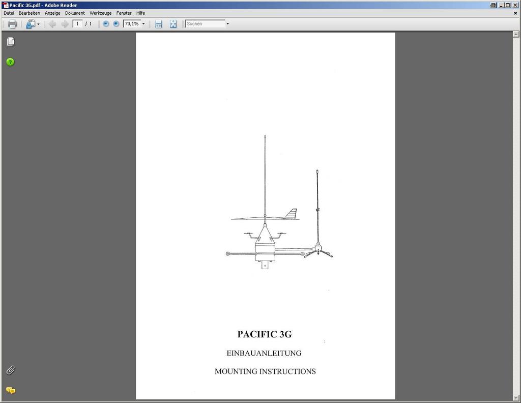
 1 Installation der Antennenanlage PACIFIC 3G Die Antennenanlage PACIFIC 3G besteht aus den Einzelantennen DELTA 200 S, DELTA 3 G und DELTA 12 M, die zu einer Einheit zusammengesetzt montiert werden. Antennenstandort:
ANTENNENSYSTEM PACIFIC EINBAUANLEITUNG ANTENNA SYSTEM PACIFIC MOUNTING INSTRUCTIONS
 ANTENNENSYSTEM PACIFIC EINBAUANLEITUNG ANTENNA SYSTEM PACIFIC MOUNTING INSTRUCTIONS Installation der Antennenanlage PACIFIC Die Antennenanlage PACIFIC besteht aus den Einzelantennen DELTA 200 S, DELTA
Alpha 3V EINBAUANLEITUNG MOUNTINGINSTRUCTIONS
 Alpha 3V EINBAUANLEITUNG MOUNTINGINSTRUCTIONS Installation der Antennenanlage Alpha 3V Die Antennenanlage Alpha 3V besteht aus der Antenne Alpha 3V und dem Antennenverteiler DB2C. Standort der Antenne
Alpha 1C EINBAUANLEITUNG MOUNTINGINSTRUCTIONS
 Alpha 1C EINBAUANLEITUNG MOUNTINGINSTRUCTIONS Installation der Antennenanlage Alpha 1C Die Antennenanlage Alpha 1C besteht aus der Antenne Alpha 1C und dem Antennenverteiler DB1C. Auf die Antenne Alpha
AKTIVE DVB-T ZIMMERANTENNE ANSCHLUSSHINWEISE ACTIVE DVB-T INDOOR ANTENNA CONNECTION INSTRUCTIONS
 K la vi er l ac ko p tik AKTIVE DVB-T ZIMMERANTENNE ANSCHLUSSHINWEISE ACTIVE DVB-T INDOOR ANTENNA CONNECTION INSTRUCTIONS ZA 8970 DRUCKS0682.indd 1 05.09.12 15:15 VerpAckunGsinhAlT UKW / UHF / VHF Flachantenne
Installation Instructions
 EN DE Installation Instructions WLAN Installation Kit, 300 Mbps, 5 GHz, 16 dbi AK-4 Wireless Kit Scope of delivery Junction box AK-4 (1x) 1 Connection board AK-4 CB with 12VDC power supply unit (1x) 2
CABLE TESTER. Manual DN-14003
 CABLE TESTER Manual DN-14003 Note: Please read and learn safety instructions before use or maintain the equipment This cable tester can t test any electrified product. 9V reduplicated battery is used in
Installation guide for Cloud and Square
 Installation guide for Cloud and Square 1. Scope of delivery 1.1 Baffle tile package and ceiling construction - 13 pcs. of baffles - Sub construction - 4 pcs. of distance tubes white (for direct mounting)
Einbauanleitung Komfort CAN Bus Interface 62240
 Einbauanleitung Komfort CAN Bus Interface 62240 Wichtiger Hinweis vor dem Einbau: Bitte beachten Sie generell beim Einbau von elektronischen Baugruppen in Fahrzeugen die Einbaurichtlinien und Garantiebestimmungen
ABB i-bus EIB. EIB Power Supply Units
 ABB i-bus EIB EIB Power Supply Units Product Range Overview EIB Power Supplies ABB STOTZ-KONTAKT GmbH, 2002 - SK 029 F 02 E Product Range Overview EIB Power Supplies! EIB Power Supply, 320 ma SV/S 30.320.5!
Anwendungsbeispiele Verstärker Application Examples Amplifiers
 Anwendungsbeispiele Verstärker Application Examples Amplifiers Anwendungsbeispiele Application examples Multimedia-Verteilung in Sternstruktur über Abzweiger Multimedia distribution in star structure
UWC 8801 / 8802 / 8803
 Wandbedieneinheit Wall Panel UWC 8801 / 8802 / 8803 Bedienungsanleitung User Manual BDA V130601DE UWC 8801 Wandbedieneinheit Anschluss Vor dem Anschluss ist der UMM 8800 unbedingt auszuschalten. Die Übertragung
RS232-Verbindung, RXU10 Herstellen einer RS232-Verbindung zwischen PC und Messgerät oder Modem und Messgerät
 Betriebsanleitung RS232-Verbindung, RXU10 Herstellen einer RS232-Verbindung zwischen PC und Messgerät oder Modem und Messgerät ä 2 Operating Instructions RS232 Connection, RXU10 Setting up an RS232 connection
High Side Laserdiodentreiber mit TEC Controller
 High Side Laserdiodentreiber mit TEC Controller Einstellten des Laserdiodentreibers 1) Potentiometer A BIAS und A GAIN durch Drehen gegen den Uhrzeigersinn (25 Umdrehungen) in Nullstellung bringen. 2)
AU-D2. Coaxial/Optical Audio Converter OPERATION MANUAL
 AU-D2 Coaxial/Optical Audio Converter OPERATION MANUAL Table of Contents 1. Introduction 1 2. Features 1 3. Operation Controls and Functions 2 3.1 Input Panel Diagram 2 3.2 Output Panel Diagram 2 3.3 Switcher
FLACHSICHERUNGSDOSEN BLADE FUSE BOXES
 FLACHSICHERUNGSDOSEN ES Flachsicherungsdosen 15 00 00 und Varianten Die Flachsicherungsdosen und Zentralstecker gibt es in zwei-, vier-, sechs- und achtpoliger Ausführung und in den Farben schwarz, natur,
1 Allgemeine Information
 1 Allgemeine Information ACHTUNG! Der Betriebsdruck der Klasse 867 ist 6 bar. Sollte der Druck Ihrer Versorgungsleitung höher als 6 bar sein, muss der Druck an der Versorgungseinheit der Nähmaschine auf
Service. Bedienelement / operating panel
 Service Bedienelement / operating panel 21 894 000 21 895 000 21 892 000 21 893 000 Dampfdusche Serie 500 Seite Seite 2-7 2-7 Steam shower series 500 page page 2-7 2-7 Dampfdusche Serie 600 Seite Seite
Hazards and measures against hazards by implementation of safe pneumatic circuits
 Application of EN ISO 13849-1 in electro-pneumatic control systems Hazards and measures against hazards by implementation of safe pneumatic circuits These examples of switching circuits are offered free
p^db=`oj===pìééçêíáåñçêã~íáçå=
 p^db=`oj===pìééçêíáåñçêã~íáçå= Error: "Could not connect to the SQL Server Instance" or "Failed to open a connection to the database." When you attempt to launch ACT! by Sage or ACT by Sage Premium for
A VGA monitor of the highest resolution that you will be using on any computer in the installation A PS/2 Keyboard A PS/2 Mouse
 PS/2 KVM SWITCH 2-PORT Vision 331217 Requirements Console A VGA monitor of the highest resolution that you will be using on any computer in the installation A PS/2 Keyboard A PS/2 Mouse Computers The following
Umschaltadapter/ Changeover / Trennadapter Disconnection Adapter für LSA-PLUS NT for LSA-PLUS NT. Montageanweisung Mounting Instructions
 Umschaltadapter/ Changeover / Trennadapter Disconnection Adapter für LSA-PLUS NT for LSA-PLUS NT Montageanweisung Mounting Instructions Der Umschalter dient zum unterbrechungsfreien Umschalten von Installations-drähten
Montageanleitung Assembly Instruction Werkbank mit 6 Schubladen/ 2 Türen
 1 Montageanleitung Assembly Instruction Werkbank mit 6 Schubladen/ 2 Türen Art. 25733 Art. 45700 Allgemeine Hinweise: Prüfen Sie bitte vor Zusammenbau, ob alle Teile vorhanden und unbeschädigt sind. Sollte
Anschlussadapterset SWR-MC
 Anschlussadapterset SWR-MC Kurzanleitung: Anschluss des PV-Generators an einen Sunny Boy Autor: Y. Siebert Dok.-Nr.: SWR-MC-11:ED1406 - Version: 1.2 Material-Nr.: Beschreibung des SWR-MC Adaptersets Mit
miditech 4merge 4-fach MIDI Merger mit :
 miditech 4merge 4-fach MIDI Merger mit : 4 x MIDI Input Port, 4 LEDs für MIDI In Signale 1 x MIDI Output Port MIDI USB Port, auch für USB Power Adapter Power LED und LOGO LEDs Hochwertiges Aluminium Gehäuse
LED Treiber: Anschlussschemata LED driver: connection diagrams
 Treiber: Anschlussschemata driver: connection diagrams TCI DC MAXI JOLLY DALI für 18W (Konstantstromversorgung), 500mA, dimmbar via Taster (Push) / 1-10V / DALI 6Z1851 Sicherheitshinweise Montagehinweise
Quick Guide Home Network Mode
 Quick Guide Home Network Mode English > 1 German > 3 About the Home Network Mode EN Tivizen Nano & iplug normally work on their own created networks (whose SSID starts with tivizentv or iplug ) in which
Westfalia Bedienungsanleitung. Nr
 Bedienungsanleitung Nr. 107375 Bedienungsanleitung Satelliten Finder RL-TC-0101 Artikel Nr. 54 25 97 Instruction Manual Satellite Finder RL-TC-0101 Article No. 54 25 97 Benutzung Funktionsumfang Regelbare
Bedienungsanleitung Netzwerkkabeltester ST-45 v2
 Bedienungsanleitung Netzwerkkabeltester ST-45 v2 Einführung Geehrter Kunde, wir möchten Ihnen zum Erwerb Ihres neuen Kabeltesters gratulieren! Mit dieser Wahl haben Sie sich für ein Produkt entschieden,
Softwareupdate-Anleitung // Porty L 600 / Porty L 1200
 Softwareupdate-Anleitung // Porty L 600 / Porty L 1200 1 Softwareupdate-Anleitung // Porty L 600 / Porty L 1200 HENSEL-VISIT GmbH & Co. KG Robert-Bunsen-Str. 3 D-97076 Würzburg-Lengfeld GERMANY Tel./Phone:
Please do not use in live circuits. When the POWER LED does not light, you must change the battery for testing.
 L A N / U S B C A B L E T E S T E R I n s t a l l a t i o n 1 2 9 9 6 4 1. I n t r o d u c t i o n The LAN/USB Cable Tester is designed to easily read the correct cable pin out configuration. The cables
MU-307 A SAFETY INSTRUCTIONS SICHERHEITSHINWEISE FEATURES MERKMALE
 SAFETY INSTRUCTIONS Read all safety instruction before operating the amplifiers. 1. Install equipment as follow condition: - Install at flat place, not bending curved. - Do not install near the water and
CAN-Bus RPM adapter. User Manual Anwender-Beschreibung
 CAN-Bus RPM adapter COT02 User Manual Anwender-Beschreibung Stand: 12.02.03 GRABAU Computertechnik GmbH Elsener Str. 30 33102 Paderborn Tel: +49 5251 1367-0 Fax: +49 5251 1367-30 Email: info@grabau.de
Schutzart IP 20 protection degree IP 20 18
 MODUL L 196 Pendelleuchte / suspended luminaire MONTAGE / MOUNTING 010-614. 009-282. 010-095 24 V DC / 40 W 010-613. 009-281. 010-094 24 V DC / 45 W Schutzart IP 20 protection degree IP 20 18 max. 1500
MultiPortSwitch. VGA Umschalter. Version 1.0 As of April 19 th 2004 Subject to change!
 MultiPortSwitch VGA Umschalter Version 1.0 As of April 19 th 2004 Subject to change! Document version: Version Date Name Comment 1.00 29.03.2004 J. Klein Compiled Distributed by: idata industrielle Datensysteme
(825M) 2-Draht-Sender
 2-Draht-Sender") Kamera SKS Bussystem 300004 (825M) 2-Draht-Sender 1. Installation Gefahr für Personen durch einen elektrischen Schlag. Verbrennungsgefahr, Geräteschäden und Fehlfunktionen. Bei der Installation sind die
Kamera SKS Bussystem 300004 (825M) 2-Draht-Sender 1. Installation Gefahr für Personen durch einen elektrischen Schlag. Verbrennungsgefahr, Geräteschäden und Fehlfunktionen. Bei der Installation sind die
INSTALLATION AND OPERATING INSTRUCTIONS FOR LPS203-M LPS203-M 操 作 指 示
 BEDIENUNGSANLEITUNG To comply with the published safety standards, the following must be observed when using this power supply. Um den zur Zeit gültigen Sicherheitsbestimmungen zu genügen, müssen die nachstehenden
Installation manual / Montageanleitung WBC2 splice patch with Fibertray Spleissung/Rangierung mit Fibertray
 Content of Assembly Instruction I. Required tools II. Required parts III. Installation Inhalt der Montageanleitung I. Benötigte Werkzeuge II. Benötigte Teile III. Installation I. Required tools: I. Benötigtes
HEAG 151, 152, 153, 154 Digital Converter
 Montage- und Betriebsanleitung Installation and operating instructions MB095-11055704 Baumer_HEAG151-152-153-154_II_DE-EN (16A1) HEAG 151, 152, 153, 154 Digital Converter 1-2 Allgemeine Hinweise - Funktionsweise
User Manual Bedienungsanleitung. www.snom.com. snom Wireless Headset Adapter snom Schnurlos-Headset-Adapter. English. Deutsch
 English snom Wireless Headset Adapter snom Schnurlos-Headset-Adapter Deutsch User Manual Bedienungsanleitung 2007 snom technology AG All rights reserved. Version 1.00 www.snom.com English snom Wireless
3. Technical data 3. Technische Daten
 661 078 3. Technical data 3. Technische Daten Design / Bauart Pressure switch, vacuum switch and differential pressure switch / Druckwellenschalter, Vakuumschalter und Differenzdruckschalter Function
Cable Tester NS-468. Safety instructions
 Cable Tester NS-468 Safety instructions Do not use the cable tester NS-468 if it is damaged. This device is only for use inside dry and clean rooms. This device must be protected from moisture, splash
Batterie-Identifikations-Modul EL-BIM
 Bedienungs- und Montageanleitung Batterie-Identifikations-Modul EL-BIM 1.0 Allgemeines Das Batterie-Identifikations-Modul EL-BIM ermöglicht eine eindeutige Zuordnung von Ladevorgang und Batterie in den
Schutzart IP 20 protection degree IP 20 18
 MODUL L 196 Pendelleuchte / suspended luminaire MONTAGE / MOUNTING 010-614. 009-282. 010-095 direktstrahlend / direct beam 010-613. 009-281. 010-094 mit Indirektlichtanteil / with indirect light component
Betriebsarten-Umschalter Common mode / Differential mode switch
 Betriebsarten-Umschalter Common mode / Differential mode switch Beschreibung: Der Betriebsarten-Umschalter CMDM 87 erweitert die Messmöglichkeiten zweier V-Netznachbildungen um die einer T- und Delta-Netznachbildung.
Seitenkoffer Topcases Gepäckträger Lock it System Softbags Aluminiumkoffer Lederkoffer Schutzbügel Hauptständer Chopper-Parts Quad-Parts Accessoires
 Zusatzscheinwerfer Art.-Nr.: 730.105 Montage Seitenkoffer Topcases Gepäckträger Lock it System Aluminiumkoffer Lederkoffer Schutzbügel Hauptständer Chopper-Parts Quad-Parts Accessoires Stück Bestellnr.
MONTAGEANLEITUNG / SHORT INSTRUCTION MANUAL
 1. Sichere Position des Statives / Secure position of tripod 2. Bestandteile für Montage der Kranstütze / Parts for assembling of column 3. 2 Teflonscheiben auflegen / Assembling of two teflon-coated discs
How-To-Do. Hardware Configuration of the CC03 via SIMATIC Manager from Siemens
 How-To-Do Hardware Configuration of the CC03 via SIMATIC Manager from Siemens Content Hardware Configuration of the CC03 via SIMATIC Manager from Siemens... 1 1 General... 2 1.1 Information... 2 1.2 Reference...
Cameraserver mini. commissioning. Ihre Vision ist unsere Aufgabe
 Cameraserver mini commissioning Page 1 Cameraserver - commissioning Contents 1. Plug IN... 3 2. Turn ON... 3 3. Network configuration... 4 4. Client-Installation... 6 4.1 Desktop Client... 6 4.2 Silverlight
LED Treiber: Anschlussschemata LED driver: connection diagrams
 ED Treiber: Anschlussschemata ED driver: connection diagrams TCI DC JOY MD für 18W ED (Konstantstromversorgung), 500mA, dimmbar via Phasenabschnittsdimmer / Taster (Push) 6Z 18 50 Sicherheitshinweise Montagehinweise
Auf Spannungsfreiheit prüfen! / De-energized and check zero-potential!
 Installationshinweise zum Einbau der LED-Röhre Dragon mit T8/G13 Sockel (Austausch) Installation Instruction for LED tube Dragon with T8/G13 socket (Replacement) A-1. Einzelschaltung mit KVG / VVG 1) Single
1: Descrew the org device of the E53 (non navi model) and cutout the plastic frame till vertical side plates (next pic), best use a dremel like tool
 and cutout the plastic frame till vertical side plates (next pic), best use a dremel like tool") Mounting- Instruction BMW E53 Doppel-DIN 31.6.2009 This mounting instruction shows you the best way for an exclusive installation for the double- DIN device, good luck!!! 1 1: Descrew the org device of
Mounting- Instruction BMW E53 Doppel-DIN 31.6.2009 This mounting instruction shows you the best way for an exclusive installation for the double- DIN device, good luck!!! 1 1: Descrew the org device of
CL I IP20. 9MX056 MDU-PWR Starter Set/Extension Set. Mounting instructions. New Installation/Neuinstallation. 9MX056 MDU-PWR Starter Set
 9MX0 MDU-PWR Starter Set/Extension Set Mounting instructions IP0 CL I a New Installation/Neuinstallation 9MX0 MDU-PWR Starter Set Page/Seite b Retrofit/Nachrüstung 9MX0 MDU-PWR Starter Set Electrical connection
Cloud Square. Montageanleitung Installation guide. OWAconsult collection
 Cloud Square Montageanleitung Installation guide OWAconsult collection 2 Montageanleitung für Cloud und Square 1. Lieferumfang 1. Scope of delivery 1.1 Lamellen- und Konstruktionspaket Tile package and
Laser LightmaXX CLUB 2.0 / 4.0 SERIES
 Seite 1 von 8 Laser LightmaXX CLUB 2.0 / 4.0 SERIES ACHTUNG! Seite 2 von 8 Laserschutzbestimmungen: Durch die starke Bündelung des Laserstrahls ist die gesamte Lichtenergie auf eine geringe Fläche konzentriert.
CLE. Heatpipe-System Kühlleistung > 30W. Heatpipe-System Kühlleistung > 25W. Heatpipe-System Kühlleistung > 25W. Heatpipe-System Kühlleistung > 20W
 LED FORTIMO KÜHLKÖRPER led fortimo heat sink system www.cardanlight.com CLE CARDAN LIGHT EUROPE CLE FORTIMO ADAPTER IP20 XFFO100....GR..SW..WS silbergrau weiß 19,90 CLE FORTIMO Adapter für CLE kardanische
Aufgabenstellung Mit welchen SICLOCK Produkten kann ich einen PC Zeitsynchronisieren?
 SICLOCK Application Note AN-0005 Titel Synchronisation von PCs mit SICLOCK Aufgabenstellung Mit welchen SICLOCK Produkten kann ich einen PC Zeitsynchronisieren? Schlüsselwörter SICLOCK DCFRS, WinGPS, GPS1000,
Markengeschichte. Hingabe unterscheidet uns. Hartnäckigkeit beschreibt uns.
 Bedienungsanleitung Mit unserem Glauben gehen wir voran. Mit unserer Leidenschaft steigern wir unsere Erfahrung. Vergessen die eigenen Fehlschläge, aber nicht das unerfüllte Potential. Die Leidenschaft
E/A-Bedieneinheit. I/O Control unit 658552 DE/GB 08/02
 E/A-Bedieneinheit I/O Control unit 527429 658552 DE/GB 08/02 Best.-Nr.: 658552 Benennung: DATENBLATT Bezeichnung: D:LP-BED.EINH.-E/A-DE/GB Stand: 08/2002 Autoren: Christine Löffler Grafik: Doris Schwarzenberger
Gestockte Log.-Per.-Breitband-Antenne Stacked Log.-Per.-Broadband Antenna
 Gestockte Log.-Per.-Breitband-Antenne Stacked Log.-Per.-Broadband Antenna Beschreibung: Die STLP 9129 ist eine gestockte Log.-Per.- Breitband Antenne für Störfestigkeitsprüfungen im Frequenzbereich von
Hinweisblatt indication sheet
 Seite page 1 von of 7 Hinweisblatt indication sheet Typ: / type: Leuchtstoffleuchten (z.b.: 50010400, 53500100) Kurzbezeichnung: Lampenwechsel bei Leuchtstoffleuchten short term: exchange of fluorescent
Beipackzettel Instruction leaflet
 Beipackzettel Instruction leaflet Montage an einen Wandarm Mounting to wall arm Pepperl+Fuchs GmbH Antoniusstr. 21 D-73249 Wernau Germany Tel.: +49(0) 621 776-3712 Fax: +49(0) 621 776-3729 www.pepperl-fuchs.com
Hama GmbH & Co KG Postfach Monheim/Germany Tel. +49 (0)9091/502-0 Fax +49 (0)9091/
9091/502-0 Fax +49 (0)9091/") www.hama.de Hama GmbH & Co KG Postfach 80 86651 Monheim/Germany Tel. +49 (0)9091/502-0 Fax +49 (0)9091/502-274 hama@hama.de www.hama.de 00062248-05.05 Multimedia Kit für/for Audi Naviplus/ VW/Seat/Skoda
www.hama.de Hama GmbH & Co KG Postfach 80 86651 Monheim/Germany Tel. +49 (0)9091/502-0 Fax +49 (0)9091/502-274 hama@hama.de www.hama.de 00062248-05.05 Multimedia Kit für/for Audi Naviplus/ VW/Seat/Skoda
Fundamentals of Electrical Engineering 1 Grundlagen der Elektrotechnik 1
 Fundamentals of Electrical Engineering 1 Grundlagen der Elektrotechnik 1 Chapter: Operational Amplifiers / Operationsverstärker Michael E. Auer Source of figures: Alexander/Sadiku: Fundamentals of Electric
LED Konverter: Anschlussschemata LED converter: connection diagrams
 LED Konverter: Anschlussschemata LED converter: connection diagrams TCI DC MAXI JOLLY DALI 48V DC, 48W (Konstantspannungsversorgung), dimmbar via Taster (Push) / 1-10V / DALI 6Z 48 10 00 Sicherheitshinweise
Order Number Bestellnummer. Hand crimp tool Handcrimpzange Positioner Einsatz Positioner Einsatz. Order Number. Bestellnummer
 Crimpingtools for Miniature Connectors Crimpwerkzeuge für Miniatursteckverbinder Hand Crimp Tool M22520/2-01 for Machined Contacts Handcrimpzange M22520/2-01 für gedrehte Kontakte Die / Einsatz Hand crimp
Softwareupdate-Anleitung // AC Porty L Netzteileinschub
 1 Softwareupdate-Anleitung // AC Porty L Netzteileinschub Softwareupdate-Anleitung // AC Porty L Netzteileinschub HENSEL-VISIT GmbH & Co. KG Robert-Bunsen-Str. 3 D-97076 Würzburg-Lengfeld GERMANY Tel./Phone:
Optische Rückumsetzer Optical Converter OPM-QTS OPM-QMS. Bedienungsanleitung/ Operating manual V2
 Optische Rückumsetzer Optical Converter OPM-QTS OPM-QMS Bedienungsanleitung/ Operating manual 0901734 V2 Beschreibung Die optischen Rückumsetzer OPM-QTS und OPM-QMS von Polytron, wandeln ein optisches
ALL1681 Wireless 802.11g Powerline Router Quick Installation Guide
 ALL1681 Wireless 802.11g Powerline Router Quick Installation Guide 1 SET ALL1681 Upon you receive your wireless Router, please check that the following contents are packaged: - Powerline Wireless Router
Mini OEM Sender / Mini OEM Transmitter
 Mini OEM Sender / Mini OEM Transmitter Kanalwahlschalter Schaltkanal 6V Ausführung auf Anfrage Channel selector Switching channel 6V version on request 5.8GHz Bereich / range 7558 004510 SupraLink Mini
EL-21SY. 2 in, 1 out v1.3 HDMI Switcher OPERATION MANUAL
 EL-21SY 2 in, 1 out v1.3 HDMI Switcher OPERATION MANUAL Table of Contents 1. Introduction 1 2. Features 1 3. Package Contents 1 4. Operation Controls and Functions 2 4.1 Front Panel Diagram 2 4.2 Rear
Technical Specification. Technische Spezifikation
 Technical Technische Technical Schurter s range of "Audio, DC and DIN Connectors" offers a cost effective solution for a wide range of applications. Technische Schurter s Sortiment an Audio, DC und DIN
NPLC NPLC 8500 Netznachbildung NPLC 8500 Line Impedance Stabilization Network
 NPLC 8500 Netznachbildung NPLC 8500 Line Impedance Stabilization Network Beschreibung: Die Netznachbildung NPLC 8500 wurde speziell für PLC-Messungen in Anlehnung an die ITU-T G.9901 entwickelt. Um die
Radio Frequency Systems
 Radio Frequency Systems by Manfred Thumm and Werner Wiesbeck Forschungszentrum Karlsruhe in der Helmholtz - Gemeinschaft Universität Karlsruhe (TH) Research University founded 1825 Receiver Forschungszentrum
VGM. VGM information. HAMBURG SÜD VGM WEB PORTAL - USER GUIDE June 2016
 Overview The Hamburg Süd VGM-Portal is an application which enables to submit VGM information directly to Hamburg Süd via our e-portal web page. You can choose to insert VGM information directly, or download
USB -> Seriell Adapterkabel Benutzerhandbuch
 USB -> Seriell Adapterkabel Benutzerhandbuch 1. Produkt Eigenschaften 1 2. System Vorraussetzungen 1 3. Treiber Installation (Alle Windows Systeme) 1 4. Den COM Port ändern 2 5. Einstellen eines RS232
WCA 3FM. Installation instruction Anleitung Installationsvejledning
 WCA 3FM Field bus card with BACnet MSTP / RS 485 / Modbus RTU interface for WSC 310/320 Plus & WCC 310/320 Plus Feldbuskarte mit BACnet MSTP / RS 485 / Modbus RTU Interface für WSC 310/320 Plus & WCC 310/320
SICHERHEITSHINWEISE STROMER LADEGERÄT SAFETY INSTRUCTIONS STROMER CHARGERS
 SICHERHEITSHINWEISE STROMER LADEGERÄT SAFETY INSTRUCTIONS STROMER CHARGERS 1 SICHERHEITSHINWEISE FÜR DAS LADEGERÄT Sie können den Akku Ihres Stromers laden, wenn er in Ihrem S-Pedelec installiert ist.
Level 2 German, 2013
 91126 911260 2SUPERVISOR S Level 2 German, 2013 91126 Demonstrate understanding of a variety of written and / or visual German text(s) on familiar matters 9.30 am Monday 11 November 2013 Credits: Five
BNC - Programm BNC Programme
 - Programm S. 215 Adapter Adapters S. 217 -Adapterleitungen adapter leads S. 218 Sicherheits-Adapter Safety adapters www.schuetzinger.de 213 - Programm Die HF-Steckverbindung der Serie ist die häufigste
VGM. VGM information. HAMBURG SÜD VGM WEB PORTAL USER GUIDE June 2016
 Overview The Hamburg Süd VGM Web portal is an application that enables you to submit VGM information directly to Hamburg Süd via our e-portal Web page. You can choose to enter VGM information directly,
TomTom WEBFLEET Tachograph
 TomTom WEBFLEET Tachograph Installation TG, 17.06.2013 Terms & Conditions Customers can sign-up for WEBFLEET Tachograph Management using the additional services form. Remote download Price: NAT: 9,90.-/EU:
Parameter-Updatesoftware PF-12 Plus
 Parameter-Updatesoftware PF-12 Plus Mai / May 2015 Inhalt 1. Durchführung des Parameter-Updates... 2 2. Kontakt... 6 Content 1. Performance of the parameter-update... 4 2. Contact... 6 1. Durchführung
Robotino View Kommunikation mit OPC. Communication with OPC DE/EN 04/08
 Robotino View Kommunikation mit OPC Robotino View Communication with OPC 1 DE/EN 04/08 Stand/Status: 04/2008 Autor/Author: Markus Bellenberg Festo Didactic GmbH & Co. KG, 73770 Denkendorf, Germany, 2008
BMW F 800 GS Motorschutzbügel Nr.: schwarz Nr.: titan
 Motorschutzbügel Nr.: 50.65 00 0 schwarz Nr.: 50.65 00 99 titan Der Bausatz umfaßt die folgenden Teile: Stück Bestellnr. Bezeichnung 705.50 Motorschutzbügel links 705.5 Motorschutzbügel rechts Schraubensatz:
Release Notes BRICKware 7.5.4. Copyright 23. March 2010 Funkwerk Enterprise Communications GmbH Version 1.0
 Release Notes BRICKware 7.5.4 Copyright 23. March 2010 Funkwerk Enterprise Communications GmbH Version 1.0 Purpose This document describes new features, changes, and solved problems of BRICKware 7.5.4.
TriASS Schreibtische. TriASS Schreibtischsystem Montageanleitung. TriASS Desking System Assembly Instructions. Das Assmann Prinzip. Gute Arbeit.
 Das Assmann Prinzip. Gute Arbeit. TriASS Schreibtischsystem Montageanleitung TriASS Desking System Assembly Instructions The Assmann principle. Designed to work well. TriASS Desks Schreibtisch, Typ ST16
Cisco SSPA122. Installation und manuelle Rekonfiguration. Dokumentenversion 1
 Cisco SSPA122 Installation und manuelle Rekonfiguration Dokumentenversion 1 Placetel UC-One Cisco SPA122 Installation und manuelle Rekonfiguration Copyright Hinweis Copyright 2015 finocom AG Alle Rechte
Installation Zellprotektor
 Installation Betrifft nur SunWare Solarmodule mit dreiadrigem Anschlusskabel! Version 2012!Wichtige Hinweise! Bevor Sie Ihr Solarmodul in Betrieb nehmen dürfen, muss zunächst 3adriges Anschlusskabel der
Zebra is offering a free replacement service and provides detailed information about the issue and procedure under the following link:
 Zebra Technologies Corporation Recalls Power Supply Units for Thermal Printers Due to Potentially Overheating or Fire Hazard: Relevant for Dürkopp Adler Industrial Sewing Machines Class 550-867 Dear Madam
Level 1 German, 2016
 90886 908860 1SUPERVISOR S Level 1 German, 2016 90886 Demonstrate understanding of a variety of German texts on areas of most immediate relevance 2.00 p.m. Wednesday 23 November 2016 Credits: Five Achievement
Integrated Control Unit for CL-PU-KST... Grease Pumps. Integriertes Steuergerät für Fettpumpen CL-PU-KST...
 Integrated Control Unit for CL-PU-KST... Grease Pumps Integriertes Steuergerät für Fettpumpen CL-PU-KST... Electric grease pumps, Modell: CL-PU-KST... 12 / 24VDC Series 24/12 V DC Elektrische Fettpumpe,
FR777 Differenzial-Kulissenauszug Bodenmontage, 200 kg Tragkraft, mit Gegenführung
 http://www.fulterer.com http://www.fultererusa.com Instructions F777 Differenzial-Kulissenauszug Bodenmontage, 00 kg Tragkraft, mit Gegenführung F777 Progressive-Action Pantry Pull-out, Bottom Mount 450