The enclosure of the module provides a degree of protection IP20 according to EN
|
|
|
- Hinrich Böhm
- vor 5 Jahren
- Abrufe
Transkript
1
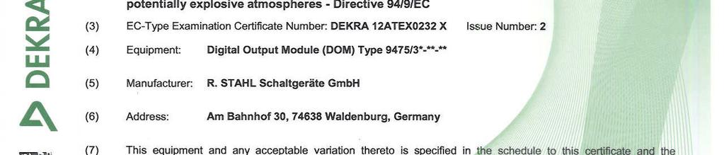
2 (13) SCHEDULE (14) to EC-Type Examination Certificate DEKRA 12ATEX0232 X Issue No. 2 (15) Description Digital Output Module (DOM) Type 9475/3*-**-**, for operation in the Remote I/O Systems IS1 and IS1+. The module is connected to the system via a Bus Rail and it provides up to eight intrinsically safe output circuits for connection of passive, galvanically isolated and unearthed actuators like solenoid, piezo and booster valves. Optionally the Digital Output Module is equipped with an active and a passive Plant-STOP Input to switch off all digital outputs at once. The intrinsically safe output and input circuits are infallibly galvanically isolated from the IS1 and IS1+ bus supply and data circuits up to a peak voltage of 60 V. Module type 9475/32-**-** is intrinsically safe and can be installed in an explosive gas atmosphere requiring equipment of category 2 G. Module type 9475/33-**-** is in type of protection Ex na and can be installed in an explosive gas atmosphere requiring equipment of category 3 G. These modules can be installed in an explosive dust atmosphere requiring equipment of category 2 D or 3 D if mounted in a suitable enclosure. The output circuits of Modules Type 9475/3*-**-e* (with e = 1-6) are intrinsically safe Ex ia or Ex ib; the output circuits of Modules Type 9475/3*-**-7* are intrinsically safe Ex ib. The enclosure of the module provides a degree of protection IP20 according to EN The Digital Output Modules Type 9475/3*-**-** may be disconnected or connected to the IS1 or IS1+ Bus Rail while in operation. Ambient temperature range -40 C to +75 C. Electrical data Circuit connecting to the IS1 or IS1+ System: Power supply (input); Plug to BusRail V101/ Pin 7, 8, 9, 10 (+), Pin 27, 28, 29, 30 ( ): in type of protection intrinsic safety Ex ia IIC, with the following maximum values: U i = 26,2 V. The circuit is equipped with an internal current limitation that limits the current to 450 ma. Address- and Databus (communication); Plug to BusRail V101/ Pin: 4 (Bus Red.); 5 (Bus Prim.); 14, 15, 16, 24 (Bank 1-4) ; 1, 11, 21 (Mod. Select): in type of protection intrinsic safety Ex ia IIC, only for connection to the internal Address- and Databus of the IS1/IS1+ System with the following maximum values: U o = 6,6 V; I o = 102 ma; P o = 168 mw U i = 6,6 V; C i = 0 nf; L i = 0 mh Electronic switch control (input); Plug to BusRail V101/ Pin 18, 19: in type of protection intrinsic safety Ex ia IIC, with the following maximum values: U o = 26,2 V; I o = 5,4 ma. Page 2/8 Form 100
3 (13) SCHEDULE (14) to EC-Type Examination Certificate DEKRA 12ATEX0232 X Issue No. 2 Intrinsically safe field circuits: 8-Channel Devices Model 9475/3*-08-**: X1 Channel 0 (1+/2-); Channel 1 (3+/4-); up to; Channel 7 (15+/16-) 4 Channel Devices Model 9475/3*-04-**: X1 Channel 0 (1+/2-); Channel 1 (5+/6-); Channel 2 (9+/10-); Channel 3 (13+/14-) The values of L o and C o in the following tables are the maximum values for combined inductance and capacitance (including cable inductance and capacitance). The values for L o and C o marked in grey are the values determined according to the curves and tables of EN , Annex A. These grey marked values may be used for the assessment as per EN , clause The internal capacitance per channel is already taken into account in the L o and C o values shown in the tables below. The internal inductance is negligibly small. Type 9475/3*-04-1* 4 output circuits in type of protection intrinsic safety Ex ia IIB/IIC, Ex ia IIIC with the following maximum values (per channel): U o = 19,7 V, I o = 142 ma, P o = 698 mw (linear source), C i = 11 nf; L i = 0 mh. L O [mh] 1,3 1,1 0,5 0,2 0,1 0,05 C O [nf] L O [mh] 7,5 5,0 2,0 0,5 0,2 0,1 0,05 C O [nf] in type of protection intrinsic safety Ex ib IIB/IIC, Ex ib IIIC with the following maximum values (per channel): U o = 19,7 V, I o = 53,8 ma, P o = 617 mw (trapezoidal characteristic, bent at 11,8 V / 52,7 ma), C i = 11 nf; L i = 0 mh. L O [mh] 3,1 2,0 0,6 0,5 0,2 0,1 0,05 C O [nf] L O [mh] 27, ,0 0,2 0,1 0,05 C O [nf] Page 3/8 Form 100
4 (13) SCHEDULE (14) to EC-Type Examination Certificate DEKRA 12ATEX0232 X Issue No. 2 Type 9475/3*-04-2* 4 output circuits in type of protection intrinsic safety Ex ia IIB/IIC, Ex ia IIIC with the following maximum values (per channel): U o = 25,7 V, I o = 110 ma, P o = 708 mw (linear source), C i = 7,2 nf; L i = 0 mh. L O [mh] 1,45 0,75 0,5 0,37 0,2 0,1 0,05 C O [nf] L O [mh] 10,0 5,0 2,0 1,0 0,5 0,2 0,1 C O [nf] in type of protection intrinsic safety Ex ib IIB/IIC, Ex ib IIIC with the following maximum values (per channel): U o = 25,7 V, I o = 49,5 ma, Po = 648 mw (trapezoidal characteristic, bent at 13,6 V / 48,5 ma), C i = 7,2 nf; L i = 0 mh. L O [mh] 1,5 1,0 0,86 0,5 0,37 0,2 0,1 C O [nf] L O [mh] ,0 1,0 0,5 0,2 0,1 C O [nf] Type 9475/3*-04-3* 4 output circuits in type of protection intrinsic safety Ex ia IIB/IIC, Ex ia IIIC with the following maximum values (per channel): U o = 26,0 V, I o = 90 ma, P o = 585 mw (linear source), C i = 5,2 nf; L i = 0 mh. L O [mh] 2,44 2,2 1,0 0,5 0,38 0,2 0,05 C O [nf] L O [mh] ,0 0,5 0,2 0,1 C O [nf] in type of protection intrinsic safety Ex ib IIB/IIC, Ex ib IIIC with the following maximum values (per channel): U o = 26,0 V, I o = 50,4 ma, P o = 508 mw (trapezoidal characteristic, bent at 10,4 V / 49,7 ma), C i = 5,2 nf; L i = 0 mh. L O [mh] 3,4 2,4 2,0 1,0 0,5 0,39 0,2 C O [nf] L O [mh] ,0 0,5 0,2 0,1 0,05 C O [nf] Page 4/8 Form 100
5 (13) SCHEDULE (14) to EC-Type Examination Certificate DEKRA 12ATEX0232 X Issue No. 2 Type 9475/3*-08-4* 8 output circuits in type of protection intrinsic safety Ex ia IIB/IIC, Ex ia IIIC with the following maximum values (per channel): U o = 11,5 V, I o = 74,8 ma, P o = 216 mw (linear source), C i = 5,2 nf; L i = 0 mh. L O [mh] 7,9 5,0 2,0 1,0 0,5 0,2 0,05 C O [nf] L O [mh] ,0 1,0 0,2 0,02 C O [nf] in type of protection intrinsic safety Ex ib IIB/IIC, Ex ib IIIC with the following maximum values (per channel): U o = 11,5 V, I o = 39,2 ma, P o = 194 mw (trapezoidal characteristic, bent at 5,1 V / 38,4 ma), C i = 5,2 nf; L i = 0 mh. L O [mh] ,0 2,0 1,0 0,5 0,05 C O [nf] L O [mh] ,0 1,0 0, C O [nf] Type 9475/3*-08-5* 8 output circuits in type of protection intrinsic safety Ex ia IIB/IIC, Ex ia IIIC with the following maximum values (per channel): U o = 19,4 V, I o = 143 ma, P o = 692 mw (linear source), C i = 16,5 nf; L i = 0 mh. L O [mh] 1,44 1,4 0,65 0,5 0,2 0,1 0,05 C O [nf] L O [mh] 7,5 5,0 2,0 0,5 0,2 0,1 0,02 C O [nf] Page 5/8 Form 100
6 (13) SCHEDULE (14) to EC-Type Examination Certificate DEKRA 12ATEX0232 X Issue No. 2 in type of protection intrinsic safety Ex ib IIB/IIC, Ex ib IIIC with the following maximum values (per channel): U o = 19,4 V, I o = 37,8 ma, P o = 506 mw (trapezoidal characteristic, bent at 14,0 V / 36,5 ma), C i = 16,5 nf; L i = 0 mh. L O [mh] 6,3 2,0 0,65 0,5 0,2 0,1 0,05 C O [nf] L O [mh] ,0 0,2 0,1 0,02 C O [nf] Type 9475/3*-08-6* 8 output circuits in type of protection intrinsic safety Ex ia IIB/IIC, Ex ia IIIC with the following maximum values (per channel): U o = 25,7 V, I o = 107 ma, P o = 688 mw (linear source), C i = 5,2 nf; L i = 0 mh. L O [mh] 1,57 1,1 1,0 0,9 0,5 0,2 0,1 C O [nf] L O [mh] 11 5,0 1,0 0,5 0,2 0,1 0,05 C O [nf] in type of protection intrinsic safety Ex ib IIB/IIC, Ex ib IIIC with the following maximum values (per channel): U o = 25,7 V, I o = 26,3 ma, P o = 468 mw (trapezoidal characteristic, bent at 19,1 V / 24,9 ma), C i = 5,2 nf; L i = 0 mh. L O [mh] 7,0 5,0 2,0 1,0 0,5 0,2 0,05 C O [nf] L O [mh] ,0 0,5 0,2 0,1 0,05 C O [nf] Page 6/8 Form 100
7 (13) SCHEDULE (14) to EC-Type Examination Certificate DEKRA 12ATEX0232 X Issue No. 2 Type 9475/3*-04-7* 4 output circuits in type of protection intrinsic safety Ex ib IIB/IIC, Ex ib IIIC with the following maximum values (per channel): U o = 15,4 V, I o = 115,4 ma, P o = 1475 mw (trapezoidal characteristic, bent at 13,2 V / 112,4 ma), C i = 33 nf; L i = 0 mh. Allowed external capacitance and inductance for group IIC: L O [mh] 0,11 0,1-0,05 0,02 0,01 C O [nf] When using cables with a maximum line length of 700 m, with a cable inductance of L c 1 µh/m, a cable capacitance of C c 200 pf/m and a cable resistance of R c 10,76 mω/m, the following values for C o and L o remain: L O [m] 0,05 C O [nf] 217 Allowed external capacitance and inductance for group IIB and IIIC: L O [mh] 2,9 2,0 1,0 0,5 0,05 0,02 C O [nf] When using cables with a maximum line length of 2000 m, with a cable inductance of L c 1 µh/m, a cable capacitance of C c 200 pf/m and a cable resistance of R c 10,76 mω/m, the following values for C o and L o remain: L O [mh] 2,0 1,0 0,5 0,02 C O [nf] Plant STOP Plant-STOP I circuit, connector X3 terminals 1 (+) and 2 (-): in type of protection intrinsic safety Ex ia IIB/IIC, Ex ia IIIC with the following maximum values: U o = 5,1 V, I o = 0,44 ma, P o = 0,50 mw (linear source), C i = 5,2 nf; L i = 0 mh. L O [mh] ,0 1,0 0,2 0,01 C O [nf] L O [mh] ,0 1,0 0,2 0,01 C O [nf] Plant-STOP II circuit, connector X3 terminals 3 and 4: in type of protection intrinsic safety Ex ia IIB/IIC, Ex ia IIIC, for connection of an intrinsically safe circuit, with the following maximum values: U i = 30 V, R i = 4940 Ω, C i = 0 nf; L i = 0 mh The Plant-STOP II circuit at X3 is galvanically isolated from all other intrinsically safe circuits. Installation instructions The instructions provided with the equipment shall be followed in detail to assure safe operation. Page 7/8 Form 100
8 (13) SCHEDULE (14) to EC-Type Examination Certificate DEKRA 12ATEX0232 X Issue No. 2 (16) Test Report No. NL/DEK/ExTR /01. (17) Special conditions for safe use When installed in an explosive gas atmosphere, the Digital Output Module (DOM) Type 9475/3*- **-** shall be placed in an enclosure that meets the requirements of an appropriate, recognized type of protection in accordance with EN When installed in an explosive dust atmosphere, the Digital Output Module (DOM) Type 9475/3*- **-** shall be placed in an enclosure that meets the requirements of type of protection protection by enclosure t, or equivalent. (18) Essential Health and Safety Requirements Covered by the standards listed at (9). (19) Test documentation As listed in Test Report No. NL/DEK/ExTR /01. Page 8/8 Form 100


9
10 (13) ANLAGE (14) zur EG-Baumusterprüfbescheinigung DEKRA 12ATEX0232 X Ausgabe Nr. 2 (15) Beschreibung Das Digital Output Modul (DOM) Typ 9475/3*-**-** für Betrieb in den Remote I/O Systemen IS1 und IS1+. Das Modul wird über die BusRail an das System angeschlossen und liefert bis zu 8 eigensichere Ausgangssignale für den Anschluss von passiven, galvanisch getrennten und ungeerdeten Aktoren wie Magnetventile, Piezo- und Boosterventile. Optional ist das Digital Output Modul mit einem aktiven und einem passiven Anlagen-AUS Eingang ausgestattet, womit alle Digitalausgänge gleichzeitig abgeschaltet werden können. Die eigensicheren Eingangs- / Ausgangschnittstellen sind bis zu einem Scheitelwert von 60 V sicher galvanisch von den IS1 und IS1+ Busversorgungs- und Datenstromkreisen getrennt. Modul Typ 9475/32-**-** ist eigensicher und kann in gasexplosionsgefährdeten Bereichen die Betriebsmittel der Kategorie 2 G erfordern, installiert werden. Modul Typ 9475/33-**-** entspricht der Zündschutzart Ex na und kann in gasexplosionsgefährdeten Bereichen die Betriebsmittel der Kategorie 3 G erfordern, installiert werden. Beide Module können in staubexplosionsgefährdeten Bereichen die Betriebsmittel der Kategorie 2 D oder 3 D erfordern, installiert werden, wenn sie in einem geeigneten Gehäuse eingebaut sind. Die Ausgangsstromkreise von Typ 9475/3*-**-e* (mit e = 1-6) sind entsprechend der Schutzart Ex ia oder Ex ib eigensicher. Die Ausgangsstromkreise von Typ 9475/3*-**-7* sind entsprechend der Schutzart Ex ib eigensicher. Das Modulgehäuse ist entsprechend der Schutzart IP20 nach EN ausgeführt. Die Digital Output Module Typ 9475/3*-**-** können im Betrieb von der IS1 oder IS1+ BusRail gezogen oder auf sie gesteckt werden. Umgebungstemperaturbereich -40 C bis +75 C. Elektrische Daten IS1 oder IS1 + Systeminterne Stromkreise: Hilfsenergie (Eingang); Steckverbinder zur BusRail V101/Pin 7, 8, 9, 10 (+), Pin 27, 28, 29, 30 (-): in Zündschutzart Eigensicherheit Ex ia IIC, mit folgendem Höchstwert: U i = 26,2 V. Der Stromkreis ist mit einer internen Strombegrenzung ausgerüstet, die den Strom auf 450 ma begrenzt. Adress-und Datenbus (Kommunikation); Steckverbinder zur BusRail V101/Pin 4 (Bus Red), 5 (Bus Prim); 14, 15, 16, 24 (Bank 1-4); 1, 11, 21 (Mod select): in Zündschutzart Eigensicherheit Ex ia IIC, nur zum Anschluss an den internen Adress- und Datenbus des IS1/IS1+ Systems mit den folgenden Höchstwerten: U o = 6,6 V; I o = 102 ma; P o = 168 mw U i = 6,6 V; C i = 0 nf; L i = 0 mh Seite 2/8 Form 103
11 (13) ANLAGE (14) zur EG-Baumusterprüfbescheinigung DEKRA 12ATEX0232 X Ausgabe Nr. 2 Ansteuerung elektronischer Schalter (Eingang); Steckverbinder zur BusRail V101/Pin 18, 19: in Zündschutzart Eigensicherheit Ex ia IIC, mit folgenden Höchstwerten: U o = 26,2 V; I o = 5,4 ma. Eigensichere Stromkreise: 8-Kanal Typ 9475/3*-08-**: X1 Kanal 0 (1+/2-); Kanal 1 (3+/4-); bis Kanal 7 (15+/16-) 4-Kanal Typ 9475/3*-04-**: X1 Kanal 0 (1+/2-); Kanal 1 (5+/6-); Kanal 2 (9+/10-); Kanal 3 (13+/14-) Die Werte von L o und C o in den folgenden Tabellen, sind die zulässigen maximalen Werte für die kombinierte Induktivität und Kapazität (inklusive Kabel Induktivität und Kapazität). Die in den Tabellen grau markierten Werte von L o und C o sind nach den Kurven und Tabellen von EN Anhang A bestimmt. Diese grau markierten Werte können für die Beurteilung nach EN Kapitel berücksichtigt werden. Die interne Kapazität pro Kanal ist in den C o Werten der nachfolgenden Tabellen bereits berücksichtigt. Die interne Induktivität ist vernachlässigbar klein. Type 9475/3*-04-1* 4 Ausgangsstromkreise in Zündschutzart Eigensicherheit Ex ia IIB/IIC, Ex ia IIIC, mit den folgenden Höchstwerten (pro Kanal): U o = 19,7 V, I o = 142 ma, P o = 698 mw (Lineare Kennlinie), C i = 11 nf; L i = 0 mh. L O [mh] 1,3 1,1 0,5 0,2 0,1 0,05 C O [nf] L O [mh] 7,5 5,0 2,0 0,5 0,2 0,1 0,05 C O [nf] in Zündschutzart Eigensicherheit Ex ib IIB/IIC, Ex ib IIIC, mit den folgenden Höchstwerten (pro Kanal): U o = 19,7 V, I o = 53,8 ma, P o = 617 mw (Trapezförmige Kennlinie, Knickpunkt 11,8 V / 52,7 ma), C i = 11 nf; L i = 0 mh. L O [mh] 3,1 2,0 0,6 0,5 0,2 0,1 0,05 C O [nf] L O [mh] 27, ,0 0,2 0,1 0,05 C O [nf] Seite 3/8 Form 103
12 (13) ANLAGE (14) zur EG-Baumusterprüfbescheinigung DEKRA 12ATEX0232 X Ausgabe Nr. 2 Type 9475/3*-04-2* 4 Ausgangsstromkreise in Zündschutzart Eigensicherheit Ex ia IIB/IIC, Ex ia IIIC, mit den folgenden Höchstwerten (pro Kanal): U o = 25,7 V, I o = 110 ma, P o = 708 mw (Lineare Kennlinie), C i = 7,2 nf; L i = 0 mh. L O [mh] 1,45 0,75 0,5 0,37 0,2 0,1 0,05 C O [nf] L O [mh] 10,0 5,0 2,0 1,0 0,5 0,2 0,1 C O [nf] in Zündschutzart Eigensicherheit Ex ib IIB/IIC, Ex ib IIIC, mit den folgenden Höchstwerten (pro Kanal): U o = 25,7 V, I o = 49,5 ma, P o = 648 mw (Trapezförmige Kennlinie, Knickpunkt 13,6 V / 48,5 ma), C i = 7,2 nf; L i = 0 mh. L O [mh] 1,5 1,0 0,86 0,5 0,37 0,2 0,1 C O [nf] L O [mh] ,0 1,0 0,5 0,2 0,1 C O [nf] Type 9475/3*-04-3* 4 Ausgangsstromkreise in Zündschutzart Eigensicherheit Ex ia IIB/IIC, Ex ia IIIC, mit den folgenden Höchstwerten (pro Kanal): U o = 26,0 V, I o = 90 ma, P o = 585 mw (Lineare Kennlinie), C i = 5,2 nf; L i = 0 mh. L O [mh] 2,44 2,2 1,0 0,5 0,38 0,2 0,05 C O [nf] L O [mh] ,0 1,0 0,5 0,2 0,1 C O [nf] in Zündschutzart Eigensicherheit Ex ib IIB/IIC, Ex ib IIIC, mit den folgenden Höchstwerten (pro Kanal): U o = 26,0 V, I o = 50,4 ma, P o = 508 mw (Trapezförmige Kennlinie, Knickpunkt 10,4 V / 49,7 ma), C i = 5,2 nf; L i = 0 mh. L O [mh] 3,4 2,4 2,0 1,0 0,5 0,39 0,2 C O [nf] L O [mh] ,0 0,5 0,2 0,1 0,05 C O [nf] Seite 4/8 Form 103
13 (13) ANLAGE (14) zur EG-Baumusterprüfbescheinigung DEKRA 12ATEX0232 X Ausgabe Nr. 2 Type 9475/3*-08-4* 8 Ausgangsstromkreise in Zündschutzart Eigensicherheit Ex ia IIB/IIC, Ex ia IIIC, mit den folgenden Höchstwerten (pro Kanal): U o = 11,5 V, I o = 74,8 ma, P o = 216 mw (Lineare Kennlinie), C i = 5,2 nf; L i = 0 mh. L O [mh] 7,9 5,0 2,0 1,0 0,5 0,2 0,05 C O [nf] L O [mh] ,0 1,0 0,2 0,02 C O [nf] in Zündschutzart Eigensicherheit Ex ib IIB/IIC, Ex ib IIIC, mit den folgenden Höchstwerten (pro Kanal): U o = 11,5 V, I o = 39,2 ma, P o = 194 mw (Trapezförmige Kennlinie, Knickpunkt 5,1 V / 38,4 ma), C i = 5,2 nf; L i = 0 mh. L O [mh] ,0 2,0 1,0 0,5 0,05 C O [nf] L O [mh] ,0 1,0 0,2 0,02 C O [nf] Type 9475/3*-08-5* 8 Ausgangsstromkreise in Zündschutzart Eigensicherheit Ex ia IIB/IIC, Ex ia IIIC, mit den folgenden Höchstwerten (pro Kanal): U o = 19,4 V, I o = 143 ma, P o = 692 mw (Lineare Kennlinie C i = 16,5 nf; L i = 0 mh. L O [mh] 1,44 1,4 0,65 0,5 0,2 0,1 0,05 C O [nf] L O [mh] 7,5 5,0 2,0 0,5 0,2 0,1 0,02 C O [nf] in Zündschutzart Eigensicherheit Ex ib IIB/IIC, Ex ib IIIC, mit den folgenden Höchstwerten (pro Kanal): U o = 19,4 V, I o = 37,8 ma, P o = 506 mw (Trapezförmige Kennlinie, Knickpunkt 14,0 V / 36,5 ma), C i = 16,5 nf; L i = 0 mh. L O [mh] 6,3 2,0 0,65 0,5 0,2 0,1 0,05 C O [nf] L O [mh] ,0 0,2 0,1 0,02 C O [nf] Seite 5/8 Form 103
14 (13) ANLAGE (14) zur EG-Baumusterprüfbescheinigung DEKRA 12ATEX0232 X Ausgabe Nr. 2 Type 9475/3*-08-6* 8 Ausgangsstromkreise in Zündschutzart Eigensicherheit Ex ia IIB/IIC, Ex ia IIIC, mit den folgenden Höchstwerten (pro Kanal): U o = 25,7 V, I o = 107 ma, P o = 688 mw (Lineare Kennlinie), C i = 5,2 nf; L i = 0 mh. L O [mh] 1,57 1,1 1,0 0,9 0,5 0,2 0,1 C O [nf] L O [mh] 11 5,0 1,0 0,5 0,2 0,1 0,05 C O [nf] in Zündschutzart Eigensicherheit Ex ib IIB/IIC, Ex ib IIIC, mit den folgenden Höchstwerten (pro Kanal): U o = 25,7 V, I o = 26,3 ma, P o = 468 mw (Trapezförmige Kennlinie, Knickpunkt 19,1 V / 24,9 ma), C i = 5,2 nf; L i = 0 mh. L O [mh] 7,0 5,0 2,0 1,0 0,5 0,2 0,05 C O [nf] L O [mh] ,0 0,5 0,2 0,1 0.,05 C O [nf] Seite 6/8 Form 103
15 (13) ANLAGE (14) zur EG-Baumusterprüfbescheinigung DEKRA 12ATEX0232 X Ausgabe Nr. 2 Type 9475/3*-04-7* 4 Ausgangsstromkreise in Zündschutzart Eigensicherheit Ex ib IIB/IIC, Ex ib IIIC, mit den folgenden Höchstwerten (pro Kanal): U o = 15,4 V, I o = 115,4 ma, P o = 1475 mw (Trapezförmige Kennlinie, Knickpunkt 13,2 V/ 112,4 ma), C i = 33 nf; L i = 0 mh. Zulässige externe Kapazität und Induktivität für Gruppe IIC: L O [mh] 0,11 0,1-0,05 0,02 0,01 C O [nf] Bei Verwendung von Kabeln mit Kabelinduktivität L c 1 µh/m, Kabelkapazität C c 200 pf/m und Kabelwiderstand R c mω/m, verbleiben bei einer Leitungslänge von 700 m folgende Werte für C o und L o. L O [mh] 0,05 C O [nf] 217 Zulässige externe Kapazität und Induktivität für die Gruppen IIB und IIIC: L O [mh] 2,9 2,0 1,0 0,5 0,05 0,02 C O [nf] Bei Verwendung von Kabeln mit Kabelinduktivität L c 1 µh/m, Kabelkapazität C c 200 pf/m und Kabelwiderstand R c mω/m, verbleiben bei einer Leitungslänge von 2000 m folgende Werte für C o und L o. L O [mh] 2,0 1,0 0,5 0,02 C O [nf] Plant STOP Plant-STOP I Stromkreis, Stecker X3 Signal 1 (+) und 2 (-): in Zündschutzart Eigensicherheit Ex ia IIB/IIC, Ex ia IIIC mit den folgenden Höchstwerten: U o = 5,1 V, I o = 0,44 ma, P o = 0,50 mw (Lineare Kennlinie), C i = 5,2 nf; L i = 0 mh. L O [mh] ,0 1,0 0,2 0,01 C O [nf] L O [mh] ,0 1,0 0,2 0,01 C O [nf] Plant-STOP II Stromkreis, Stecker X3 Signal 3 und 4: in Zündschutzart Eigensicherheit Ex ia IIB/IIC, Ex ia IIIC, für den Anschluss von eigensicheren Stromkreisen, mit den folgenden Höchstwerten: U i = 30 V, R i = 4940 Ω, C i = 0 nf; L i = 0 mh Der Plant-STOP II Stromkreis, an X3, ist galvanisch getrennt von allen anderen eigensicheren Stromkreisen. Seite 7/8 Form 103
16 (13) ANLAGE (14) zur EG-Baumusterprüfbescheinigung DEKRA 12ATEX0232 X Ausgabe Nr. 2 Errichtungshinweise Um die sichere Funktion der Geräte zu gewährleisten ist die Betriebsanleitung des Herstellers genau zu befolgen. (16) Prüfbericht Nr. NL/DEK/ExTR /01. (17) Besondere Bedingungen für die sichere Anwendung Für die Errichtung in gasexplosionsgefährdeten Bereichen ist das Digital Output Modul (DOM) Typ 9475/3*-**-** in ein Gehäuse einzubauen, das die Anforderungen einer anerkannten Zündschutzart nach EN erfüllt. Für die Errichtung in staubexplosionsgefährdeten Bereichen ist das Digital Output Modul (DOM) Typ 9475/3*-**-** in ein Gehäuse einzubauen, das die Anforderungen der Zündschutzart Geräte- Staubexplosionsschutz durch Gehäuse "t", oder gleichwertig, erfüllt. (18) Grundlegende Sicherheits- und Gesundheitsanforderungen Von den Normen unter (9) abgedeckt. (19) Prüfungsunterlagen Wie erwähnt in Prüfbericht Nr. NL/DEK/ExTR /01. Seite 8/8 Form 103
BESCHEINIGUNG EG-Baumusterprüfung
 BESCHEINIGUNG (1) EG-Baumusterprüfung (2) Geräte und Schutzsysteme zur bestimmungsgemäßen Verwendung in explosionsgefährdeten Bereichen - Richtlinie 94/9/EG (3) EG-Baumusterprüfbescheinigung Nummer: KEMA
2. Nachtrag. (Ergänzung gemäß Richtlinie 94/9/EG Anhang III Ziffer 6) zur EG-Baumusterprüfbescheinigung DMT 03 ATEX E 048
 zur EG-Baumusterprüfbescheinigung DMT 03 ATEX E 048")
 TúYTIOÐ 2.ERGANZUNG zur Besche nigungsnummer: Gerät: Hersteller Anschrift. Auftragsnummer: Ausstellungsdatum TUV 04 ATEX 2531 Messu mformer Typ KFD2-WAC2-Ex1* Pepperl + Fuchs GmbH Lilienthalstrasse 200
 TÚYrcÐ 4.ERGÄNZUNG zur Bescheinigungsnummer: Gerät: Hersteller: Anschrift. Auftragsnummer: Ausstellungsdatum TÜV 99 ATEX 1408 I mpulsauswertegerät Typ KF**-D**-Ex*.* Pepperl + Fuchs GmbH Lilienthalstrasse
ZU Endlagenschalter, elektrisch für WA 131 / 131 H Limit Switch, Electrical, for WA 131 / 131 H.
 ZU 0859 Endlagenschalter, elektrisch für WA 131 / 131 H Limit Switch, Electrical, for WA 131 / 131 H www.knick.de Bauart und Funktion Der Endlagenschalter ZU 0859 wandelt die pneumatischen Endlagen signale,
Ex-Barriere für Diagnoseeinheit SITRANS DA400 / Ex-barrier for diagnostics unit SITRANS DA400 7MJ2010-1AA 0032
 Ex-Barriere für Diagnoseeinheit SITRANS DA400 / Ex-barrier for diagnostics unit SITRANS DA400 7MJ2010-1AA 0032 Warnung Elektrischer Anschluss in explosionsgefährdeten Bereichen Anschluss und Inbetriebnahme
APPLICATION GUIDELINE
 PROCESS AUTOMATION APPLICATION GUIDELINE EN DE APPLICATION GUIDELINE WANDFLUH SOLENOID VALVE PEPPERL+FUCHS SOLENOID DRIVER ANWENDUNGSBESCHREIBUNG MANGETVENTIL WANDFLUH VENTILSTEUERBAUSTEIN PEPPERL+FUCHS
Electrical testing of Bosch common rail Injectors
 Electrical testing of Bosch common rail Injectors Contents: 1. Adapter cable for Hybridtester FSA 050 (article number 0 684 010 050 / 1 687 023 571) 2. Electrical testing of Bosch common rail solenoid
Original language english, german translation shown in italics Originalsprache Englisch, Übersetzung auf Deutsch wird in Kursivschrift gezeigt
 ... -. -. Y1. -.. /. Identification of special variant, listed in table 15.3 where relevant for the type of protection (optional) Kennzeichnung von Sonderausführungen, genannt in Tabelle 15.3 wenn relevant
Electrical tests on Bosch unit injectors
 Valid for Bosch unit injectors with order numbers 0 414 700 / 0 414 701 / 0 414 702 Parts Kit Magnet*: - F00H.N37.925 - F00H.N37.933 - F00H.N37.934 * For allocation to the 10-place Bosch order number,
CERTIFICATE PF12CERT2301X
 en (1) CERTIFICATE (2) Equipment Intended for Use in Potentially Explosive Atmospheres - Directive 2014/34/EU (3) Certificate Number: (4) Equipment: VisuNet EX2 GMP (5) Manufacturer: Pepperl+Fuchs GmbH
Electrical testing of Bosch common rail piezo injectors
 Applies to generation CRI 3: Bosch 10-position order number 0 445 115 = CRI 3-16 (CRI 3.0) 1600 bar 0 445 116 = CRI 3-18 (CRI 3.2) 1800 bar 0 445 117 = CRI 3-20 (CRI 3.3) 2000 bar Tools required: Hybrid
PROFIBUS-DP Repeater 1 to 1 and 1 to 5 with optional level converter module
 LSS PROFIBUS-DP Repeater 1 to 1 and 1 to 5 with optional level converter module The LSS PROFIBUS-DP repeaters 1 to 1 and 1 to 5 are used for coupling up to six PROFIBUS bus segments in RS 485 bus technology.
2. For Entity concept use the appropriate parameters from above to ensure the following: V t or V OC V max
 Class I, II, III, Div. 1, Group A - G or Class I, Zone 0, Group IIC/IIB Hazardous Locations Nonhazardous or Class I, Div. 2, Group A, B, C, D or Class I, Zone 2, Group IIC Hazardous Locations The copying,
BESCHEINIGUNG. Geräte und Schutzsysteme zur bestimmungsgemäßen Verwendung in explosionsgefährdeten Bereichen - Richtlinie 94/9/EG
 Übersetzung, Originalsprache: Englisch BESCHEINIGUNG (1) EG-Baumusterprüfung (2) Geräte und Schutzsysteme zur bestimmungsgemäßen Verwendung in explosionsgefährdeten Bereichen - Richtlinie 94/9/EG (3) EG-Baumusterprüfbescheinigung
Stratos Pro Series. Type A201X-*-0-T6 Type A201B-*-0-T6.
 Stratos Pro Series Type A201X-*-0-T6 Type A201B-*-0-T6 Supplement to the Stratos Pro Series Documentation Ergänzung zur Dokumentation der Stratos Pro Serie www.knick.de Measuring Channels MSPH Memosens
Messumformer- Speisegerät Supply unit for transmitters. B Betriebsanleitung Operating Instructions 03.07/
 Messumformer- Speisegerät Supply unit for transmitters B 70.7520.0 Betriebsanleitung Operating Instructions 03.07/00359391 Besonderheiten II (1) G D [EEx ia] IIC oder [EEx ia] IIB II (2) G D [EEx ib] IIC
C 1.12 C C1.12c
 Festinstallation / Permanently mounted Handmessgeräte / Hand-held instrument C 1.12 VIB 5.730 VIBROTECTOR Schwingungswächter 10 Hz - 1 khz / VIBROTECTOR vibration monitor 10 Hz - 1 khz / VIB 5.731 -, 10
Electrical testing of Bosch common rail solenoid valve (MV) injectors
 injectors") Applies to MV injector, generation: -CRI 1.0 / 2.0 / 2.1 / 2.2 -CRIN 1 / 2 / 3, with K oder AK plug Bosch 10-position order number Bosch-Bestellnummer CRI: 0 445 110 xxx Bosch-Bestellnummer CRIN: 0 445
Applies to MV injector, generation: -CRI 1.0 / 2.0 / 2.1 / 2.2 -CRIN 1 / 2 / 3, with K oder AK plug Bosch 10-position order number Bosch-Bestellnummer CRI: 0 445 110 xxx Bosch-Bestellnummer CRIN: 0 445
TÜV 02 ATEX 1833 TÜV NORD CERT
 (1) EG-Baumusterprüfbescheinigung (2) Geräte und Schutzsysteme zur bestimmungsgemäßen Verwendung in explosionsgefährdeten Bereichen - Richtlinie 94/9/EG (3) EG Baumusterprüfbescheinigungsnummer TÜV 02
Installationsanleitung / installation manual - DIMMbox
 Inhalt / Content Funktionsbeschreibung... 2 Anschlusskonfigurationen... 3 Konstantspannung... 3 Konstantstrom... 3 Art der Steuerung... 4 Analogeingang... 4 Digital Addressable Lighting Interface (DALI):...
Einbauanleitung Komfort CAN Bus Interface 62240
 Einbauanleitung Komfort CAN Bus Interface 62240 Wichtiger Hinweis vor dem Einbau: Bitte beachten Sie generell beim Einbau von elektronischen Baugruppen in Fahrzeugen die Einbaurichtlinien und Garantiebestimmungen
TÜV 99 ATEX TÜV Hannover/Sachen-Anhalt e.v. Hannover, TÜV CERT-Zertifizierungsstelle Am TÜV 1 D Hannover
 (1) EG-Baumusterprüfbescheinigung (2) Geräte und Schutzsysteme zur bestimmungsgemäßen Verwendung in explosionsgefährdeten Bereichen - Richtlinie 94/9/EG (3) EG Baumusterprüfbescheinigungsnummer TÜV 99
 Notes: This page applies to versions with extended order code: approval option: C2, C5 IO option: A, B, C, D, E, G IS / Ex ia / AEx ia installation: 1. IO option: A 30 V 300 ma 1 W 5 nf 0 2. IO option:
CABLE TESTER. Manual DN-14003
 CABLE TESTER Manual DN-14003 Note: Please read and learn safety instructions before use or maintain the equipment This cable tester can t test any electrified product. 9V reduplicated battery is used in
Datenblatt. Remote-I/O - u-remote UR20-4AO-UI or 4-wire connection; 16-bit resolution; 4 outputs
 2- or 4-wire connection; 16-bit resolution; 4 outputs The analogue output module controls up to 4 analogue actuators with +/-10 V, +/-5 V, 0...10 V, 0...5 V, 2...10 V, 1...5 V, 0...20 ma or 4...20 ma with
Konformitätserklärung / Declaration of Conformity
 1 16.06.011 Konformitätserklärung / Declaration of Conformity Wir/We Robert-Bosch-Straße 4 784 Singen Germany erklären in alleiniger Verantwortung, dass das Produkt/declare under our sole responsibility
Betriebsanleitung (Sicherheitsrelevanter Teil ATEX und IECEx) Induktive Sensoren NAMUR NN504A NN505A /00 02/2014
 Induktive Sensoren NAMUR NN504A NN505A /00 02/2014") Betriebsanleitung (Sicherheitsrelevanter Teil ATEX und IECEx) Induktive Sensoren NAMUR NN504A NN505A 80001940/00 02/2014 Hinweise für den sicheren Einsatz in explosionsgefährdeten Bereichen Bestimmungsgemäße
Betriebsanleitung (Sicherheitsrelevanter Teil ATEX und IECEx) Induktive Sensoren NAMUR NN504A NN505A 80001940/00 02/2014 Hinweise für den sicheren Einsatz in explosionsgefährdeten Bereichen Bestimmungsgemäße
EINBAUHINWEISE INSTALLATION INSTRUCTIONS
 EINBAUHINWEISE INSTALLATION INSTRUCTIONS FÜR JEDEN ANSPRUCH DAS RICHTIGE FAHRWERK. KW automotive GmbH Aspachweg 14 74427 Fichtenberg Telefon: +49 7971 9630-0 Telefax: +49 7971 9630-191 www.kwsuspensions.de
Funktionsbeschreibung/ Montageanweisung Steuermodul DSM 400 für Dunstabzugshaube DA 6000 W
 Funktionsbeschreibung/ Montageanweisung Steuermodul DSM 400 für Dunstabzugshaube DA 6000 W Operation/Installation Control module DSM 400 for Cooker Hood DA 6000 W de, en M.-Nr. 09 165 660 Inhalt/Contents
Daten Visualisierung - VS -
 Technische Spezifikationen TECHNISCHE SPEZIFIKATIONEN DATENBLÄTTER - VS - Änderungen im Sinne des technischen Fortschritts vorbehalten Technische Spezifikationen 2008 VS-00 Technische Specifikation EX
JX3-PS1. Installationsanleitung. Version Lieferumfang
 JX3-PS1 Spannungsversorgungsmodul Jetter AG Kontakte: Gräterstraße 2 E-Mail - Vertrieb: sales@jetter.de D-71642 Ludwigsburg E-Mail - Hotline: hotline@jetter.de Germany Telefon - Hotline: +49(0)7141/2550-444
1. Januar Quellen:
 WHITEPAPER Einsatz von Murrelektronik MICO-Modulen für die Realisierung eines Low-Voltage Limited Energy Circuits in Industrial Control Panels (Steuer- und Schaltschränken) nach UL508A 1. Januar 2014 Quellen:
Valid for confirmation of protection type:
 Hinweis zu den beiliegenden Ex-Zertifikaten ( z.b. Baumusterprüfbescheinigung ) Information regarding Ex certificates ( i.e. type-examination certificate) Da die offiziellen Zertifikate auf den jeweiligen
Messumformer-Speisegerät
 JUMO GmbH & Co. KG Telefon: 49 661 6003-727 Hausadresse: Moritz-Juchheim-Straße 1, 36039 Fulda, Germany Telefax: 49 661 6003-508 Lieferadresse: Mackenrodtstraße 14, 36039 Fulda, Germany E-Mail: mail@jumo.net
1> DEKRA. (2) - Richtlinie 94/9/EG Geräte und Schutzsysteme zur bestimmungsgemäßen Verwendung in explosionsgefährdeten Bereichen
 - Richtlinie 94/9/EG Geräte und Schutzsysteme zur bestimmungsgemäßen Verwendung in explosionsgefährdeten Bereichen") (1) EG-Baumusterprüfbescheinigung (2) - Richtlinie 94/9/EG Geräte und Schutzsysteme zur bestimmungsgemäßen erwendung in explosionsgefährdeten Bereichen (3) BS 10 ATEX E 110 X (4) Gerät: Massedurchfluss-Umformer
(1) EG-Baumusterprüfbescheinigung (2) - Richtlinie 94/9/EG Geräte und Schutzsysteme zur bestimmungsgemäßen erwendung in explosionsgefährdeten Bereichen (3) BS 10 ATEX E 110 X (4) Gerät: Massedurchfluss-Umformer
EINBAUHINWEISE INSTALLATION INSTRUCTIONS
 EINBAUHINWEISE INSTALLATION INSTRUCTIONS FÜR JEDEN ANSPRUCH DAS RICHTIGE FAHRWERK. KW automotive GmbH Aspachweg 14 74427 Fichtenberg Telefon: +49 7971 9630-0 Telefax: +49 7971 9630-191 www.kwsuspensions.de
EU-Baumusterprüfbescheinigungen EU-Type Examination Certificate
 EU-Baumusterprüfbescheinigungen EU-Type Examination Certificate der Notifizierten Stelle über die Konformitätsbewertung nach ANHANG III der gemäß Richtlinie für Funkanlagen 2014/53/EU of the Notified Body
HH-Sicherungseinsätze mit Steckverbindern für Freileitungsmontage HV fuse links with plug-connectors for overheadline fitting
 G- HV fuse links with plug-connectors for overheadline fitting HH1-70 HV fuse links including connectors for overhead line fitting Hochspannungs-Sicherungen mit Anschlussgarnitur bilden einen Set, der
Betriebsanleitung Schaltverstärker N00..A N05..A / / 2014
 Betriebsanleitung Schaltverstärker N00..A N05..A 80009130 / 00 0 / 014 Hinweise für den sicheren Einsatz in explosionsgefährdeten Bereichen 1 Verwendung Geräte, die eigensichere Stromkreise beinhalten,
Certificate of conformity Generating unit, NS-protection
 Applicant: Product: Certificate of conformity Generating unit, NS-protection Schneider Electric Solar Inverters USA, Inc. 250 South Vasco Road Livermore, California 94551 USA Photovoltaic Inverter with
 1> DEKRA 4. Nachtrag (Ergänzung gemäß Richtnie 94/9/EG Anhang 111 Ziffer 6) zur EG-Baumusterprüfbescheinigung DMT 01 ATEX E 149 X Gerät: Hersteller: Anschrift: Massedurchfluss-Aufnehmer Typ TM, TME, TMU,
HEAG 151, 152, 153, 154 Digital Converter
 Montage- und Betriebsanleitung Installation and operating instructions MB095-11055704 Baumer_HEAG151-152-153-154_II_DE-EN (16A1) HEAG 151, 152, 153, 154 Digital Converter 1-2 Allgemeine Hinweise - Funktionsweise
IR RECEIVER Bedienungsanleitung User s Manual
 Bedienungsanleitung User s Manual Die zweite Generation des MBNLED RGB DMX POWER SUPPLY und des MBNLED PRO Controller RGB DMX bieten die Möglichkeit, LED Module über eine Infrarot Fernbedienung zu steuern.
Compressed air - dewpoint 10K under ambient temperature - ISO8573-1, Kl. 3 Durchflussrichtung Flow direction EIN: von 1-2 AUS: von 2 3
 3/2 Wegeventil mit PIEZO-Pilotventil Baureihe P20 3/2 way valve with Piezo-pilot valve Series P20 P20 381RF-* NW 2 Eigenerwärmungsfrei Ein Produkt für alle Ex-Bereiche Kompatibel zu Microcontrollern Kompatibel
FLINTEC Datum letzte Änderung:
 Rev. 04 Instruction and Operation Manual (IOM) Seite 1 von 9 Scope: Load Cells: PC1, PC2, PC6, PCB, SB2, SB4, SB5, SB6, SB14, SLB, BK2, ZLB, RC1, RC2, RC3, UB1, UB5, UB6. 1. Preamble This IOM represents
Systemaufbau Blockdiagramm / System structure
 Systemaufbau Blockdiagramm / System structure... 1 Leuchtenanschluß / Connection of Luminaire... 2 Unterstützte DALI Kommandos / Supported DALI commands... 2 Fehlerverhalten / Failure behavior... 5 Standards
UWC 8801 / 8802 / 8803
 Wandbedieneinheit Wall Panel UWC 8801 / 8802 / 8803 Bedienungsanleitung User Manual BDA V130601DE UWC 8801 Wandbedieneinheit Anschluss Vor dem Anschluss ist der UMM 8800 unbedingt auszuschalten. Die Übertragung
Sample connections for feedback module RM-88-N and RM-88-N-Opto!
 Kleiner Ring Heist/Germany Phone: 00 / Fax: 00 / Sample connections for feedback module RM--N and RM--N-Opto! Page. Connect the feedback modules to the digital central control units and interfaces. Connect
MultiPortSwitch. VGA Umschalter. Version 1.0 As of April 19 th 2004 Subject to change!
 MultiPortSwitch VGA Umschalter Version 1.0 As of April 19 th 2004 Subject to change! Document version: Version Date Name Comment 1.00 29.03.2004 J. Klein Compiled Distributed by: idata industrielle Datensysteme
/10
 04.2015 1/10 04.2015 2/10 04.2015 3/10 04.2015 4/10 04.2015 5/10 04.2015 6/10 SCHRAMM GMBH. POSTFACH 62 01 22. 60350 FRANKFURT AM MAIN EX Betriebsanleitung Typ WME, TME, MW08, MT08. FLINSCHSTRASSE 18a
ATEX II (1) G [Ex ia] IIC CE 0123 TPS 03 ATEX Instructions
![ATEX II (1) G [Ex ia] IIC CE 0123 TPS 03 ATEX Instructions](/thumbs/55/37136893.jpg "ATEX II (1) G [Ex ia] IIC CE 0123 TPS 03 ATEX Instructions") Qualität zertifiziert nach ISO 9001. Postfach 1106, D71301 Waiblingen Esslinger Str. 26, WN-Hegnach Tel. 07151/956230 Fax 07151/956250 E-mail: info@braun-tacho.de Internet: www.braun-tacho.de Isolating
Qualität zertifiziert nach ISO 9001. Postfach 1106, D71301 Waiblingen Esslinger Str. 26, WN-Hegnach Tel. 07151/956230 Fax 07151/956250 E-mail: info@braun-tacho.de Internet: www.braun-tacho.de Isolating
 Hazardous Locations Class I Division 1 Groups ABCD or Class I Zone 1 Groups IIC and Class II and III Division 1 Groups EFG PROMAG 5. W / P / H / L / E XP / I / 1 / ABCD; DIP / II, III / 1 / EFG AIS / I,
VDE Prüf- und Zertifizierungsinstitut Zeichengenehmigung
 2 Dieses Blatt gilt nur in Verbindung mit Blatt 1 des sausweises Nr. This supplement is only valid in conjunction with 1 of the. Schaltschrank-Heizelement Switch cabinet heating element mit Lüfter with
IDG. Drehzahlsensor / Speed Sensor
 Drehzahlen sicher erfassen, anzeigen und kontrollieren For reliable measurement, control and indication of rotational speeds Analogsignal 1-Kanal 1-channel analog signal IDG Drehzahlsensor / Speed Sensor
R&R. Ges. für Rationalisierung und Rechentechnik mbh. R&R RR-P-508 / ST106-EX1 motor-control unit
 R&R R&R RR-P-08 / ST06-EX motor-control unit housing wxhxd weight application power supply aluminum anodized approx. 6 x 8 x 8 mm housing similar to ST0 drawing DNR967 approx. 80 g motor desk control unit
AKTIVE DVB-T ZIMMERANTENNE ANSCHLUSSHINWEISE ACTIVE DVB-T INDOOR ANTENNA CONNECTION INSTRUCTIONS
 K la vi er l ac ko p tik AKTIVE DVB-T ZIMMERANTENNE ANSCHLUSSHINWEISE ACTIVE DVB-T INDOOR ANTENNA CONNECTION INSTRUCTIONS ZA 8970 DRUCKS0682.indd 1 05.09.12 15:15 VerpAckunGsinhAlT UKW / UHF / VHF Flachantenne
Geschäftsstelle Hannover, Am TÜV 1, Hannover, Tel , Fax
 ( 1 ) EU-Baumusterprüfbescheinigung TuVNORD (2) Geräte und Schutzsysteme zur bestimmungsgemäßen Verwendung in explosionsgefährdeten Bereichen, Richtlinie 2014/34/EU (3) Bescheinigungsnummer: (4) für das
1> DEKRA. 4. Nachtrag. (Ergänzung gemäß Richtlinie 94/9/EG Anhang 111Ziffer 6) zur EG-Baumusterprüfbeschein!gung BVS 03 ATEX E 233 X
 zur EG-Baumusterprüfbeschein!gung BVS 03 ATEX E 233 X") 4. Nachtrag (Ergänzung gemäß Richtlinie 94/9/EG Anhang 111Ziffer 6) zur EG-Baumusterprüfbeschein!gung BVS 03 ATEX E 233 X Gerät: Sensorik-System Typ PTF Hersteller: Ing.-Büro JANSEN Anschrift: 63512 Hainburg
4. Nachtrag (Ergänzung gemäß Richtlinie 94/9/EG Anhang 111Ziffer 6) zur EG-Baumusterprüfbeschein!gung BVS 03 ATEX E 233 X Gerät: Sensorik-System Typ PTF Hersteller: Ing.-Büro JANSEN Anschrift: 63512 Hainburg
Installation Instruction FDB M; FDB N
 Basic schematic FDB -3... Technical Data / Technische Daten Umax. AC Umax. DC Dischargecurrent C2 (total) 22 V 32 V 10 ka...m: metric...n: NPT 1/2 Dischargecurrent C2 (line -line) 0,25 ka Protection level
 Phys i kal isch-techn ische Bu ndesanstalt Braunschweig und Berlin 3. ERGÄruZUNG gemäß Richtlinie 94/9/EG Anhang lll Ziffer 6 zur EG-Baumusterprüfbescheinigung PTB 00 ATEX 2081 Gerät: Kennzeichnung Hersteller:
Certificate of conformity Generating unit, NS-protection
 Certificate of conformity Generating unit, NS-protection Applicant: Product: Schneider Electric Solar Inverters USA, Inc. 250 South Vasco Road Livermore, California 94551 USA Photovoltaic Inverter with
Bedienungsanleitung (Einbau- und Anschlusshinweise)
") Temperaturmeßtechnik Geraberg GmbH Bedienungsanleitung (Einbau- und Anschlusshinweise) Widerstandsthermometer System V...s Widerstandsthermometer für Temperaturen bis 150 C Gerätegruppe : II Gerätekategorie
Temperaturmeßtechnik Geraberg GmbH Bedienungsanleitung (Einbau- und Anschlusshinweise) Widerstandsthermometer System V...s Widerstandsthermometer für Temperaturen bis 150 C Gerätegruppe : II Gerätekategorie
PR0111-S. 16 Kanal E/A Modul / 16 Channel IO Module. Artikel-Nr. / Article-No: 50364
 PR0111-S 16 Kanal E/A Modul / 16 Channel IO Module Artikel-Nr. / Article-No: 50364 DE Einbauanweisung für den Elektroinstallateur EN Installation notes for the electrician Sicherheits- und Warnhinweise
Control Units CU240S Power Modules PM250 / PM260
 s Product Information Control Units CU240S Power Modules PM250 / PM260 Edition 11/2006 A5E01006377A Overview This product information sheet describes the behavior of inverters with Control Units CU240S
4CH AHD Digital Video Recorder kit
 4CH AHD Digital Video Recorder kit with 4x 720P outdoor fixed Lens cameras Quick Installation Guide DN-16120 Connect directly to your DVR Connecting your cameras to your DVR: 1. Find the 60ft. BNC cable,
4 Remote I/O. Digital Output Modul 4-Kanal Ausführung Reihe 9475/ ab Rev. F
 4 Remote I/O Digital Output Modul 4-Kanal Ausführung 4 Kanäle für Ex i Magnetventile, Piezo- und Boosterventile Ausgänge eigensicher Ex ia IIC Zusätzlicher Eingang für Anlagen-AUS" verfügbar (gem. IEC
Analog Input Modul HART Ex i Eingänge, Kanäle Typ 9461/
 > 4 Kanäle für 2-Leiter HART und 4 Kanäle für 4-Leiter HART > Eingänge eigensicher Ex ia IIC > Galvanische Trennung zwischen Eingängen und System > Drahtbruch- und Kurzschlussüberwachung für jeden Feldstromkreis
Zusatz zur Betriebsanleitung Addendum to the Operating Instructions
 Drive Technology \ Drive Automation \ System Integration \ Services Zusatz zur Betriebsanleitung Addendum to the Operating Instructions Austausch von MOVIGEAR -S01 durch MOVIGEAR -DSC-B Replacing MOVIGEAR
Handbuch Flash disk FD153
 Handbuch Flash disk FD153 0044 Rev.1 FD153 Hinweise für explosionsgeschützte Geräte Seite 1 1 Hinweise für explosionsgeschützte Geräte Geltungsbereich und Vorschriften Die in dieser Betriebsanleitung angegebenen
INSTALLATION AND OPERATING INSTRUCTIONS FOR LPS203-M LPS203-M 操 作 指 示
 BEDIENUNGSANLEITUNG To comply with the published safety standards, the following must be observed when using this power supply. Um den zur Zeit gültigen Sicherheitsbestimmungen zu genügen, müssen die nachstehenden
ABB i-bus EIB. EIB Power Supply Units
 ABB i-bus EIB EIB Power Supply Units Product Range Overview EIB Power Supplies ABB STOTZ-KONTAKT GmbH, 2002 - SK 029 F 02 E Product Range Overview EIB Power Supplies! EIB Power Supply, 320 ma SV/S 30.320.5!
BESCHEINIGUNG EG-Baumusterprüfung
 Übersetzung, Originalsprache: Englisch BESCHEINIGUNG (1) EG-Baumusterprüfung (2) Geräte und Schutzsysteme zur bestimmungsgemäßen Verwendung in explosionsgefährdeten Bereichen - Richtlinie 94/9/EG (3) EG-Baumusterprüfbescheinigung
Interface- und Versorgungsbaugruppe IPC 3x0i / PSC 3x0i
 Interface- und Versorgungsbaugruppe IPC 3x0i / PSC 3x0i Montageanleitung Version 10 IBS BatchControl GmbH Im Sträßchen 2 4 Tel.: +49 2241 9199801 53925 Kall Fax.: +49 2241 9199871 Germany www.ibs-batchcontrol.com
ADAMCZEWSKI. Betriebsanleitung Speisetrennverstärker AD-STVEX 710 GVD. Bestelldaten. Sicherheitsbestimmungen und Errichtungshinweise.
 Betriebsanleitung Speisetrennverstärker Der Speisetrennverstärker dient zum einen zur eigensicheren Versorgung / Speisung eines passiven eigensicheren Betriebsmittels, das im explosionsgefährdeten Bereich
INSTALLATION AND OPERATING INSTRUCTIONS FOR imp1-xxxx-xxxx-xxxx-xxxx-xxxx-xxxx-xxxx-xx
 BEDIENUNGSANLEITUNG To comply with the published safety standards, the following must be observed when using this power supply. Um den zur Zeit gültigen Sicherheitsbestimmungen zu genügen, müssen die nachstehenden
16 Kanal E/A Modul / 16 Channel IO Module. Artikel-Nr. / Article-No: 50170
 Datenblatt PR0111 Data sheet PR0111 16 Kanal E/A Modul / 16 Channel IO Module Artikel-Nr. / Article-No: 50170 DE Einbauanweisung für den Elektroinstallateur EN Installation notes for the electrician Sicherheits-
Kuhnke Technical Data. Contact Details
 Kuhnke Technical Data The following page(s) are extracted from multi-page Kuhnke product catalogues or CDROMs and any page number shown is relevant to the original document. The PDF sheets here may have
Typenreihe GY Type Group GY. Klein-Hubmagnete Small lifting solenoids
 Klein-Hubmagnete Small lifting solenoids Typenreihe GY Type Group GY Bauart Hubmagnete der Reihe GY wer den für Gleichspannungsan schluss geliefert. Die Querschnittsabmessungen (B x H) liegen zwischen
Newest Generation of the BS2 Corrosion/Warning and Measurement System
 Newest Generation of the BS2 Corrosion/Warning and Measurement System BS2 System Description: BS2 CorroDec 2G is a cable and energyless system module range for detecting corrosion, humidity and prevailing
Da die offiziellen Zertifikate auf den jeweiligen Loher Motortyp ausgestellt sind und die Dokumente nicht abgeändert werden kö
 Hinweis zu den beiliegenden Ex-Zertifikaten ( z.b. Baumusterprüfbescheinigung ) Information regarding Ex certificates ( i.e. type-examination certificate) Da die offiziellen Zertifikate auf den jeweiligen
Fundamentals of Electrical Engineering 1 Grundlagen der Elektrotechnik 1
 Fundamentals of Electrical Engineering 1 Grundlagen der Elektrotechnik 1 Chapter: Operational Amplifiers / Operationsverstärker Michael E. Auer Source of figures: Alexander/Sadiku: Fundamentals of Electric
4 Remote I/O. Digital Output Modul 8-Kanal Ausführung Reihe 9475/ ab Rev. F
 Remote I/O Digital Output Modul 8-Kanal Ausführung 8 Kanäle für Ex i Magnetventile, Piezo- und Boosterventile Ausgänge eigensicher Ex ia IIC Zusätzlicher Eingang für Anlagen-AUS" verfügbar (gem. IEC 61508;
Binärausgabe ohne Hilfsenergie Reihe 9176
 Binärausgabe ohne Hilfsenergie Reihe 9176 > Zum eigensicheren Betrieb von Ex i Magnetventilen, Leuchtmeldern und Hupen > Versorgung über Ansteuerstromkreis, schleifengespeist > Ausgang eigensicher [Ex
Joystick CHALLENGER Ji
 Betriebsanleitung Joystick CHALLENGER Ji MANUAL JI REV 1.6 DE.DOC 31.01.07 A.J. 1 Inhaltsverzeichnis Inhaltsverzeichnis...2 Einleitung...2 Ausführungsvarianten des Challenger Ji...2 Technische Daten...4
DGR CE SICHERHEITSVENTILE PED CE SAFETY VALVES
 DGR CE SICHERHEITSVENTILE PED CE SAFETY VALVES Ecksicherheitsventile aus Rotguss mit Nirofeder Typ 606 GF/GFL/tGF für neutrale Flüssigkeiten,Dampf und gasförmige Medien Safety valves made of red brass
VDE Prüf- und Zertifizierungsinstitut Zeichengenehmigung
 Blatt / page 2 Dieses Blatt gilt nur in Verbindung mit Blatt 1 des sausweises Nr.. This supplement is only valid in conjunction with page 1 of the. PV-Wechselrichter mit selbsttätiger Freischaltstelle
Betriebsanleitung MWE - System
 Betriebsanleitung MWE - System Universelles Dateninterface Typ UDI BVS 04 ATEX E 133 X über Tage eigensichere Fernleitung unter Tage Datenübertragung Typ DÜSE 5i/I BVS 04 ATEX E 071 Eigens. Stromversorgung
EUROTEC Namur Solenoid Valve
 Beschreibung Description - Kolbenschieber-Magnetventil NAMUR, indirekt gesteuert, 5/2- und 3/2-wege, mit Magnetspule und Gerätestecker mit Ausgang M16 für Kabeldurchmesser 5-6mm - Leichtes Umschalten von
JUMO Ex-i Speise- und Eingangstrennverstärker
 Seite 1/5 JUMO Ex-i Speise- und Eingangstrennverstärker Kurzbeschreibung Der JUMO Ex-i Speise- und Eingangstrennverstärker 707530 ist für den Betrieb von im Ex-Bereich installierten eigensicheren (Ex-i)
Physikalisch-Technische Bundesanstalt PTB 00 ATEX 2049 X
 Physikalisch-Technische Bundesanstalt PTB (1) EG-Baumusterprüfbescheinigung (2) Geräte und Schutzsysteme zur bestimmungsgemäßen Verwendung in explosionsgefährdeten Bereichen - Richtlinie 94/9/EG (3) EG-Baumusterprüfbescheinigungsnummer
rot red braun brown rot red RS-8 rot red braun brown R S V~
 Kleiner Ring 9 /Germany Phone: 0049 4122 / 977 381 Fax: 0049 4122 / 977 382 Sample connections: Feedback module with integrated detection of occupied tracks for the RS-feedback bus (Lenz Digital plus)
24V DC 8150/ Typschilder / Type Labels Schilder AUßEN / Labels outside Schilder INNEN / Labels inside STANDARD (AVERY)
") X700 X560 X40 X80 X40 < X0 > + X40 X80 X40 X560 X700 Y440 Y80 Y40 < Y0 > + Y40 Y80 8784_V00 DC Gesamtstückz.Pos. quantity per item ==>
X700 X560 X40 X80 X40 < X0 > + X40 X80 X40 X560 X700 Y440 Y80 Y40 < Y0 > + Y40 Y80 8784_V00 DC Gesamtstückz.Pos. quantity per item ==>
4 Remote I/O. Digital Input Modul NAMUR Ex nl Eingänge, 16 Kanäle Reihe 9470/25
 4 Remote I/O 16 Kanäle für Kontakte und NAMUR-Initiatoren (EN 60947-5-6) Zone 2 Ausführung zum Anschluss von Stromkreisen gem. Ex nl, Ex na und Nicht-Ex Galvanische Trennung zwischen Eingängen und System
Betriebsanleitung (Sicherheitsrelevanter Teil ATEX und IECEx) Induktive Sensoren NAMUR NN504A NN505A NN506A NN507A /00 08/2015
 Induktive Sensoren NAMUR NN504A NN505A NN506A NN507A /00 08/2015") Betriebsanleitung (Sicherheitsrelevanter Teil ATEX und IECEx) Induktive Sensoren NAMUR NN504A NN505A NN506A NN507A 80013497/00 08/015 Hinweise für den sicheren Einsatz in explosionsgefährdeten Bereichen
Betriebsanleitung (Sicherheitsrelevanter Teil ATEX und IECEx) Induktive Sensoren NAMUR NN504A NN505A NN506A NN507A 80013497/00 08/015 Hinweise für den sicheren Einsatz in explosionsgefährdeten Bereichen
Supplementary instructions for current output / Zusatzanleitung für Stromausgang
 Supplementary instructions for current output / Zusatzanleitung für Stromausgang 4003954401 10/2014 MA VA40 ESK AD R01-en/de Content / Inhalt 1 Safety instructions / Sicherheitshinweise... 3 1.1 General
ATEX-Check list. Compiled by: Date: Signature: Acceptable practice at the determination of flash point: Closed cup according to ISO 2719
 Fire and explosion hazard ATEX 137 1999/92/EG und ATEX 95 2014/34/EU Danger assessment and determination of explosion protection zone for the test space as well as the installation site ATEX-Check list