HR SMT Chipinduktivitäten 0603 / 0805 für höchste Zuverlässigkeitsanprüche HR SMT Chip Inductors 0603 / 0805 for High Reliability Market
|
|
|
- Gotthilf Lichtenberg
- vor 5 Jahren
- Abrufe
Transkript

1 HR SMT Chipinduktivitäten 0603 / 0805 für höchste Zuverlässigkeitsanprüche HR SMT Chip Inductors 0603 / 0805 for High Reliability Market fotolia.com Zertifiziertes QM-System: ISO/TS Version 3 ISO 9001:2008 Zertifiziertes UM-System: ISO Certified QM-System: ISO/TS Third Edition ISO 9001:2008 Certified EM-System: ISO
2 SUMIDA Componets - HR SMT Chipinduktivitäten SUMIDA Components - HR SMT Chip Inductors SUMIDA HR SMT Chip-Induktivitäten sind drahtgewickelt auf Spulenkörpern aus Ferrit- oder Keramikmaterial mit außergewöhnlich hoher Güte und hohen Resonanzfrequenzen. In verschiedenen Anwendungen treten teilweise hohe Belastungen auf und erfordern unterschiedliche Bauteileigenschaften wie erweiterten Temperaturbereich oder ein hohes Maß an Schock- und Vibrationsfestigkeit. Die SUMIDA Components HR Familie erfüllt diese anspruchsvollen Anforderungen. Unser erweitertes Angebot beinhaltet spezifische Produktmerkmale wie spezielle Anschlussbelotung zur Verbesserung des Lötverhaltens und Erhöhung der Widerstandfähigkeit der PCB-Verbindung, z. B. durch Nachverzinnen mit einem bleihaltigen Lot oder anderen RoHS-konformen Materialien. Außerdem haben wir spezielle Testmethoden und Testflows für hohe Bauteilzuverlässigkeit standartisiert. Darüber hinaus können ergänzend kundenspezifische elektrische und mechanische Tests sowie Umweltprüfungen durchgeführt werden (inkl. Dokumentation). SUMIDA HR SMT Chip Inductors are wire-wound on our proprietary formulation of ferrite or ceramic cores giving them the highest Q-factors and resonant frequencies. Different applications require different component characteristics such as extended temperature or greater levels of shock and vibration durability. These HR families of components meet the stringent requirements of these most demanding environments. Our value added options include special termination finishes to improve solder behaviour and robustness of PCB connection by tinning with either tin/lead or RoHS compatible materials. We have also established sophisticated high reliability testing and inspection flows as standards which can be extended by custom specific electrical, mechanical and environmental testing including documentation. SUMIDA Components GmbH has certified testing facilities in Asia and Europe to perform comprehensive laboratory testing services for electronic components. SUMIDA Components GmbH arbeitet mit zertifizierten Testeinrichtungen in Asien, Europa und den USA zusammen, um umfassende Labortests für unsere Bauteile durchzuführen
3 Qualifikationsprüfungen Qualification tests Die Qualifikation der HR SMT Chipinduktivitäten erfolgt nach AEC-Q200, Table 5 (induktive Bauelemente), MIL- STD-202, MIL STD 981 und ASTM E 595. The qualification of HR SMT Chip Inductances is done according to AEC-Q200, Table 5 (inductive components), MIL-STD-202, MIL 981 and ASTM E 595. AEC-Q200 Tab. 5 AEC-Q200 Tab. 5 No. Test Conditon (referenced at Tab. 5) Notes 1 Physical Dimensions 2 Electrical Characterization JESD22 Method JB-100 and SUMIDA Components Spec. AEC Q 200 and SUMIDA Components Spec Temp.: -55 C / 25 C / 125 C 3 Solderability / Resistance to dissolution of metallization J-STD Terminal Strength AEC-Q kg for 60 sec. (1,0 kg for 0603) 5 Board Flex AEC-Q mm for 60 sec. 6 Resistance to Soldering Heat J-STD High Temperature Exposure MIL-STD-202 Method 108 T = 125 C (t = 1000 hrs.) 8 Temperature Cycling / Thermal Shock MIL-STD-202 Method 107 JESD22 Method JA-104 T = -55 / 125 C (1000 cycles) 9 Biased Humidity MIL-STD-202 Method C / 85% RH (t = 1000 hrs.) 10 Mechanical Shock MIL-STD-202 Method 213 Condition C 11 Vibration MIL-STD-202 Method g 12 ESD AEC-Q Resistance to Solvents MIL-STD-202 Method Operational Life MIL-PRF-27 T = 125 C (t = 1000 hrs. with rated current) 15 Moisture Resistance MIL-STD-202 Method Sn Whisker JESD22 Mehtod A104 JESD 201 Zusatzprüfungen Additional tests No. Test Conditon Notes 17 Mechanical Shock MIL-STD-202 Method 213 Condition F 18 Vibration MIL-STD-202 Method 204 Condition H 19 Moisture Sensitivity (MSL) J-STD-020 MSL 1 20 Outgassing ASTM E Resistance to Solvents MIL-STD-202 Method 215 Bioact EC-7R Cleaner - 3 -
4 HR - Prüfungen HR Monitoring Folgende Tests können im Rahmen des Produktionsprozesses durchgeführt werden: Following test are possible during the production of the HR Chip Inductors: Prüfung (100 %) - Thermal Shock Test (= Temperature Cycling) - Hochtemperaturlagerung - Tieftemperaturlagerung - Belastungsprüfung mit Nennstrom (Burn-In) - Elektrische Parameter (L, R DC ) - Sichtkontrolle 100 % Testing - Thermal Shock Test (= Temperature Cycling) - No Load Burn-In Test (= High Temperature Storage) - Low Temperature Storage - Rated Current Burn-In - Electrical Parameter (L, R DC ) - Visual Inspection Stichprobe - Lötbarkeit - Board Flex - Haftfestigkeit der Anschlüsse - Anschliffuntersuchung - Resonanzfrequenz f res Sample Testing - Solderability - Board Flex - Terminal Strength - Cross-Sectional Microstructure - Resonance Frequency f res Auf Antfrage können weitere Test angeboten werden. Additional tests are possible on request. Messgeräte Test Equipment Induktivität L und Güte Q: RF LCR Meter: 4286 A Messaufnahme: Agilent A Inductance L and Quality Factor Q: RF LCR Meter: 4286 A Test Fixture: Agilent A Resonanzfrequenz f res : Netzwerk Analysator: Messaufnahme nach CECC: 8753E 1 mm Pad-Abstand Resonance Frequency f res : Network Analyzer: 8753E Test Fixture acc. to CECC: 1 mm pad distance R DC : gemessen bei 20 C Digital Multimeter: Burster Resistomat 2329 Messaufnahme: 4-pol-Messung R DC : measured at 20 C Digital Multimeter: Burster Resistomat 2329 Test Fixture: 4 pole measure - 4 -
5 Aufbau Constructional Feature Chipinduktivitäten 0603 / Quaderförmiger Spulenkörper aus Keramik- bzw. Ferritmaterial je nach Induktivitätswert - Zwei lötfähig metallisierte Kontaktierungsflächen aus AgPdPt oder AgPd/Ni/Sn - Wicklung: Kupferlackdraht - Wicklungsenden auf den Kontaktierungsflächen verschweißt - Nachverzinnte Kontaktierungsflächen mit SnPb oder anderen Materialien (auf Nachfrage) Chip Inductors 0603 / Coil body of ceramic or ferrite material according to inductance value - Two solderable metallized terminations of AgPdPt or AgPd/Ni/Sn - Winding: enamelled copper wire - Wire ends welded onto the terminations - Tinned terminations with SnPb or other materials (on request) Bauform mit vergossenen Windungen: Wicklung mit mechanisch und thermisch hochbeständiger sowie elektrisch neutraler Kunststoffmasse geschützt, die gleichzeitig die Windungen auf dem Spulenkörper fixiert. Type with coated windings: Windings are protected by a mechanically and thermically highly constant as well as electrically neutral plastic material which also fixes the windings in position
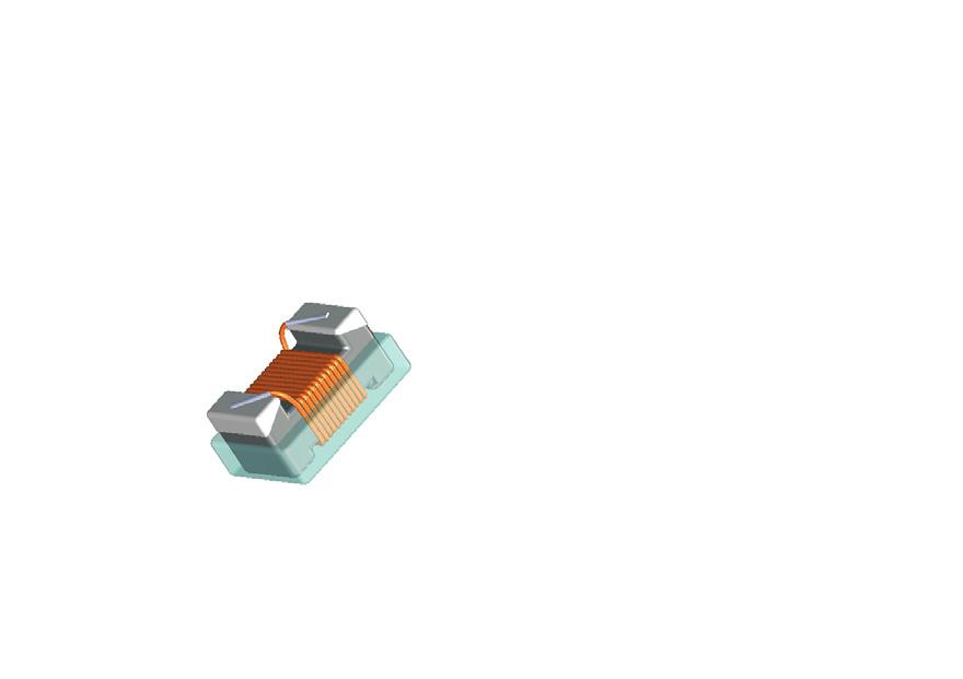
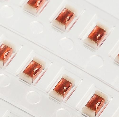
6 HR SMT Chipinduktivitäten Baugröße 0603 (1608) HR SMT Chip Inductors Size 0603 (1608) - 6 -
7 c Technische Informationen Baugröße 0603 (1608) Technical Details Size 0603 (1608) Bauteilabmessungen und Pad-Layout-Empfehlung Component Dimensions and Pad Layout Recommendation Drahtenden verschweißt (=metallisierte Fläche) / wire leads welded (=metallization area) C 0,90 ±0,15 1,2 ±0,2 +0,15 0,85-0,10 0,45 ±0,2 0 0,90-0,05 +0,10 1,60-0,05 C = Inkl. Metallisierung, Wicklung und Verguss / with metallization, winding and coating = Metallisierung / metallization = Verguss / coating 1,7 ±0,1 Bauteilabmessungen nach dem Nachverzinnen / Dimensions after tinning Layoutempfehlung / Layout recommendation: max. 1,0 a max. 1,83 max. 1,23 b a b c 0,8...1,0 2,0...2,5 0,7... Maße / Dimensions (mm) 1,0-7 -
8 Elektrische Eigenschaften Baugröße 0603 (1608) Electrical Parameters Size 0603 (1608) Keramik / Ceramic Ferrit / Ferrite Artikel-Nr. L Q min Q typ f L,Q f res,min R DC,max I rated,max Tol. Order No. 800 MHz [MHz] [MHz] [mω] [ma] [%] 5**6 015 ** *0 1, /20 5**6 018 ** *0 1, /20 5**6 033 ** *0 3, /20 5**6 036 ** *0 3, /20 5**6 039 ** *0 3, /20 5**6 047 ** *0 4, /20 5**6 056 ** *0 5, /10/20 5**6 068 ** *0 6, /10/20 5**6 082 ** *0 8, /10/20 5**6 087 ** *0 8, /10/20 5**6 100 ** * /5/10/20 5**6 120 ** * /5/10/20 5**6 150 ** * /5/10/20 5**6 180 ** * /5/10/20 5**6 220 ** * /5/10/20 5**6 270 ** * /5/10/20 5**6 330 ** * /5/10/20 5**6 390 ** * /5/10/20 5**6 470 ** * /5/10/20 5**6 560 ** * /5/10/20 5**6 680 ** * /5/10/20 5**6 820 ** * /5/10/20 5**6 101 ** * /5/10/20 5**6 121 ** * /5/10/20 5**6 151 ** * /5/10/20 5**6 181 ** * /5/10/20 5**6 221 ** * /5/10/20 5**6 271 ** * /5/10/20 5**6 331 ** * /5/10/20 5**6 391 ** * /5/10/20 5**6 471 ** * , /10/20 5**6 561 ** * , /10/20 5**6 681 ** * , /10/20 5**6 821 ** * , /10/20 5**6 102 ** * , /10/20 5**6 122 ** * , /10/20 5**6 152 ** * , /10/20 5**6 182 ** * , /10/20 5**6 222 ** * , /10/20 5**6 272 ** * , /10/20 Keramik / Ceramic Ferrit / Ferrite Zulässiger Temperaturbereich Vergossen: - 55 C C Unvergossen: - 55 C C (L > 12 nh) Permissable operating temperature range with Coating: - 55 C C without Coating: - 55 C C (L > 12 nh) - 8 -
9 Bestellhinweise Baugröße 0603 (1608) Erklärung des Artikelnummern-Schlüssels Ordering Instructions Size 0603 (1608) Explanation of Part Code 5* * * * * 0 Designation Chip Inductance size and metalization 54*6 AgPd/Ni/Sn 55*6 AgPdPt Application 0 standard M medical A aerospace W military Packing unit 0 Reels Ø 180 mm, 4000 pcs. Inductance L Multiplier for L: 10 x (example 27 nh) Abnormal order number for L-values < 10 nh Tinning 0 standard metalization T tinned version with SnPb (not in combination with Rated Current Burn-In test) Inductance Tolerance 1 ± 20 % 2 ± 10 % 3 ± 5 % 4 ± 2 % 5 ± 1 %* Coating 2 uncoated 4 coated Bestellbeispiele: Ordering examples: 54M Chip Inductor 0603, medical, L=270 nh, Tol. 5 %, coated (T=125 C), tape & reel 4000 pcs. 54A T0 Chip Inductor 0603, aerospace, L=3,6 nh, Tol. 10 %, uncoated (T=180 C), tinned version (SnPb), tape & reel 4000 pcs. * auf Anfrage / on request - 9 -
10 Elektrische Eigenschaften Baugröße 0603 (1608) Electrical Parameters Size 0603 (1608) Güte Q über Frequenz f Q factor versus frequency f Spule auf Keramikkörper Coil on ceramic body Spule auf Ferritkörper Coil on ferrite body 2 0 Q [ ] nh nh 680 nh 1800 nh 2700 nh f [MHz ]

11 Induktivität L über Frequenz f Inductance L versus frequency f Spule auf Keramikkörper Coil on ceramic body Spule auf Ferritkörper Coil on ferrite body L [nh] 2700 nh nh 1800 nh nh nh 1000 nh 680 nh nh f [MHz ]
12 Empfohlene Strombelastbarkeit I B / I N, 85 C in Abhängigkeit von der Umgebungstemperaur T a Recommended Current-carrying capacity I op / I R, 85 C depending on the ambient temperature T a IB/IN 1,2 1 0,8 Keramik Ceramic 0,6 Ferrit Ferrite 0,4 0, T a [ C ]


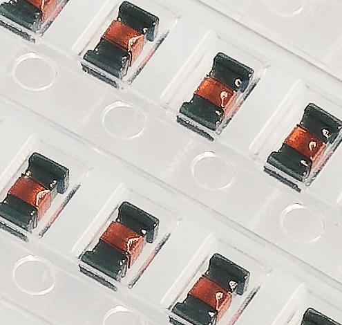
13 HR SMT Chipinduktivitäten Baugröße 0805 (2012) HR SMT Chip Inductors Size 0805 (2012)
14 c Technische Informationen Baugröße 0805 (2012) Technical Details Size 0805 (2012) Bauteilabmessungen und Pad-Layout-Empfehlung Component Dimensions and Pad Layout Recommendation 0 1,4-0,2 B max. 2,2 B A +0,1 2 0 A 0 max. 1,42 C 1,2-0,1 Drahtenden verschweißt / wire leads welded 1,4 B 0-0,2 A = Abmessungen / core dimensions B = Inkl. Metallisierung und Wicklung / with metallization and winding C = Inkl. Metallisierung, Wicklung und Verguss / with metallization, winding and coating = Metallisierung / metallization Bauteilabmessungen nach dem Nachverzinnen / Dimensions after tinning Layoutempfehlung / Layout recommendation: max. 1,43 a max. 1,45 max. 2,28 b a b c 2,8 3,2 1,0...1,2... 1,2 1,5... Maße / Dimensions (mm)
15 Elektrische Eigenschaften Baugröße 0805 (2012) Electrical Parameters Size 0805 (2012) Keramik / Ceramic Ferrit / Ferrite Artikel-Nr. L Q min Q typ f L,Q f res,min R DC,max I N,max Tol. Order No. 800 MHz [MHz] [MHz] [mω] [ma] [%] 5**8 020 ** ** 2, **8 050 ** ** 5, /20 5**8 060 ** ** 6, /20 5**8 080 ** ** 8, **8 100 ** ** /10/20 5**8 120 ** ** /10/20 5**8 150 ** ** /10/20 5**8 180 ** ** /10/20 5**8 220 ** ** /10/20 5**8 270 ** ** /10/20 5**8 330 ** ** /10/20 5**8 390 ** ** /10/20 5**8 470 ** ** /5/10/20 5**8 560 ** ** /5/10/20 5**8 680 ** ** /5/10/20 5**8 820 ** ** /5/10/20 5**8 101 ** ** /5/10/20 5**8 121 ** ** /5/10/20 5**8 151 ** ** /5/10/20 5**8 181 ** ** /5/10/20 5**8 221 ** ** /5/10/20 5**8 271 ** ** /5/10/20 5**8 331 ** ** /5/10/20 5**8 391 ** ** /5/10/20 5**8 471 ** ** /5/10/20 5**8 561 ** ** /5/10/20 5**8 681 ** ** , /10/20 5**8 821 ** ** , /10/20 5**8 102 ** ** , /10/20 5**8 122 ** ** , /10/20 5**8 152 ** ** , /10/20 5**8 182 ** ** , /10/20 5**8 222 ** ** /10/20 5**8 272 ** ** , /10/20 5**8 332 ** ** , /10/20 5**8 392 ** ** /10/20 5**8 472 ** ** /10/20 Keramik / Ceramic Ferrit / Ferrite Zulässiger Temperaturbereich Vergossen: - 55 C C Unvergossen: - 55 C C (L > 15 nh) Permissable operating temperature range with Coating: - 55 C C without Coating: - 55 C C (L > 15 nh)
16 Bestellhinweise Baugröße 0805 (2012) Erklärung des Artikelnummern-Schlüssels Ordering Instructions Size 0805 (2012) Explanation of Part Code 5* * * * * * Designation Chip Inductance size and metalization 54*8 AgPd/Ni/Sn 55*8 AgPdPt Application 0 standard tests M medical A aerospace W military Inductance L Multiplier for L: 10 x (example 27 nh) Packing unit 0 Reels Ø 180 mm pcs. 3 Reels Ø 180 mm pcs. 5 Reels Ø 180 mm pcs. Tinning 0 standard metalization T tinned version with SnPb (not in combination with Rated Current Burn-In test) Inductance Tolerance 1 ± 20 % 2 ± 10 % 3 ± 5 % 4 ± 2 % 5 ± 1 %* Coating 2 uncoated 4 coated Bestellbeispiel: Ordering examples: 54M Chip Inductor 0805, medical, L=270 nh, Tol. 2 %, coated (T=125 C), tape & reel pcs. 54W T0 Chip Inductor 0805, military, L=1,8 µh, Tol. 10 %, uncoated (T=180 C), tinned version (SnPb), tape & reel 3000 pcs. * auf Anfrage / on request
17 Elektrische Eigenschaften Baugröße 0805 (2012) Electrical Parameters Size 0805 (2012) Güte Q über Frequenz f Q factor versus frequency f Spule auf Keramikkörper Coil on ceramic body Q [ ] 10 nh nh 68 nh nh nh f [MHz ] Spule auf Ferritkörper Coil on ferrite body Q [ ] nh 2700 nh 2200 nh 1000 nh 680 nh f [MHz ]
18 Induktivität L über Frequenz f Inductance L versus frequency f Spule auf Keramikkörper Coil on ceramic body Coil on ferrite body L [nh] L [nh] nh 220 nh nH 27 nh nh f [MHz ] Spule auf Ferritkörper nh 2700 nh 2200 nh nh 680 nh f [MHz ]
19 Empfohlene Strombelastbarkeit I B / I N, 85 C in Abhängigkeit von der Umgebungstemperaur T a Recommended Current-carrying capacity I op / I R, 85 C depending on the ambient temperature T a 1,2 1 0,8 Keramik Ceramic IB/IN 0,6 Ferrit Ferrite 0,4 0, T a [ C ]


20 Allgemeine Hinweise / General Information Gurtung und Verpackung / Taping and Packing
21 Allgemeine Hinweise General Information Lagerbedingungen Für die Aufbewahrung der Bauelemente in einem Warenlager sollten die folgenden Bedingungen eingehalten werden. Die Lagerbedingungen sind bei allen Baureihen der SMD-Spulen (Bauteile gegurtet auf Rollen) anzuwenden. Lagerung: 1 Jahr ab Versanddatum Temperatur: 10 C - 35 C Rel. Luftfeuchte: 50 % - 70 % Um die zuverlässige Verarbeitung mittels Zuführ- und Bestückungseinrichtungen sicherzustellen, sollten für die angelieferten Waren bzw. gelagerten Verpackungen (Blistergurte) folgende Einflüsse vermieden werden: - Staubatmosphäre - chemische Atmosphäre - extreme Temperaturänderung - Vibrationen - direkte Sonneneinstrahlung Storage conditions For storage of components in a warehouse the following conditions should be observed. Storage conditions apply to all series of SMD coils (components taped on reel). Storage: 1 year from date of delivery Temperature: 10 C - 35 C Humidity: 50 % - 70 % To ensure reliable processing with feeding and pick and place equipment, on all delivered or stored components/ packages the following influences should be avoided: - dust atmosphere - chemical atmosphere - rapid change of temperature - vibration - direct solar radiation Verarbeitung und Montage Aufgrund der konstruktiven Beschaffenheit der Wicklungsträger (die Spulenwindungen liegen weitgehend geschützt in einer Vertiefung des Spulenkörpers) sind die Miniatur-SMD-Spulen auch zur Verarbeitung auf Längsförderern oder ähnlichen Zuführeinrichtungen von Bestückungsautomaten geeignet. Die SMD-Spulen können mittels Leitkleber aufgeklebt bzw. kontaktiert werden. Die in SMT üblichen Lötverfahren (wie z.b. Reflowlöten, Wellenlöten) können angewandt werden. Um bei der Reflowlötung eine Benetzung an den seitlichen Kontaktierungsflächen zu gewährleisten, ist für eine ausreichende Menge an Lot- und Flussmittel zu sorgen. Processing and Mounting Due to the construction (coil windings are securely in a cavity of the winding body) the SMT coils can be used for processing on linear feeder or similar mounting equipment. The SMD coils can be mounted or fixed with conductive adhesives. All customary soldering processes (e.g. reflow or wave soldering) can be used. A sufficient quantity of solder and flux should be used in order to guarantee that the lateral metallization areas are wetted during the reflow soldering process. Reinigung Die Bauteile können mit handelsüblichen Waschmitteln und den allgemein üblichen Waschmethoden gereinigt werden. Cleaning The components can be cleaned with commercial detergents and by customary methods
22 Lötprofile (Empfehlungen) Die SMD- Bauteile müssen eine gute Lötbarkeit aufweisen, damit eine sichere mechanische und elektrische Verbindung zur Leiterplatte hergestellt wird. Die Bauteile dürfen durch den Lötprozess nicht beschädigt werden. Für die Verarbeitung mit Pb-haltiger sowie Pb-freier Lotpaste mittels Reflowlötung, werden Lötprofile in Übereinstimmung mit der Prüfnorm IPC/JEDEC J-STD020D (wie nachfolgend angeführt) empfohlen. Je nach eingesetzter Lotpaste sind die Prozessparameter vom Anwender anzupassen. Profile for Pb-free applications (SAC) Recommended Soldering Profile For secure electric and mechanic connection with PCB the SMT components have to show a good solderability. The components shall not be damaged during soldering. For reflow soldering with lead-content and lead-free soldering pastes solder profiles according test specification IPC/JEDEC J-STD020D are recommended (please see profiles below). Depending on the soldering paste used process parameters have to be adjusted by the user. Profile for SnPb applications Temperature C Reflow Profile in accordance with IPC/JEDEC J-STD-020 (Pb-free) 20 s - 40 s Peak temperature: 260 C Ramp-up: max. 3 K / s 217 C max. 200 C 60 s s Temperature C Reflow Profile in accordance with IPC/JEDEC J-STD-020 (Sn-Pb) 10 s - 30 s Peak temperature: 240 C Ramp-up: max. 3 K / s 183 C 150 min. 150 C Preheat: 60 s s Ramp-down: max. 6 K / s 150 max. 150 C 60 s s Ramp-down: max. 6 K / s min. 100 C Preheat: 60 s s C to Peak: max. 8 min C to Peak: max. 6 min 0 00:00:00 00:02:00 00:04:00 00:06:00 00:08:00 00:10:00 00:12:00 00:14:00 Time 0 00:00:00 00:02:00 00:04:00 00:06:00 00:08:00 00:10:00 00:12:00 Time Prüfung der Reflow-Lötung Profilparameter: Lotpaste SAC Aufheizgradient: <1 K/s Vorwärmen (150 C-200 C): 80 s Zeit über Liquidus (217 C): 120 s Peaktemperatur: 257 C Zeit 5K unter Peaktemp.: 24 s Abkühlgradient: <1 K/s Zeit 25 C bis Peaktemp.: 5:00 min Lotpaste SnPb Aufheizgradient: <1 K/s Vorwärmen (100 C-150 C): 87 s Zeit über Liquidus (183 C): 145 s Peaktemperatur: 240 C Zeit 5K unter Peaktemp.: 20 s Abkühlgradient: <1 K/s Zeit 25 C bis Peaktemp.: 5:10 min Test reflow soldering Soldering profile: Soldering paste SAC Ramp-up: <1 K/s Preheating (150 C-200 C): 80 s Time above liquidus (217 C): 120 s Peak temperature: 257 C Time 5K below peak temp.: 24 s Ramp-down: <1 K/s Time 25 C to peak temp.: 5:00 min Soldering paste SnPb Ramp-up: <1 K/s Preheating (100 C-150 C): 87 s Time above liquidus (183 C): 145 s Peak temperature: 240 C Time 5K below peak temp.: 20 s Ramp-down: <1 K/s Time 25 C to peak temp.: 5:10 min
23 5,5 Gurtung Taping Zur automatischen Bestückung werden unsere Chipspulen für SMT in Super 8 Gurtverpackung geliefert. Die Gurtung erfolgt nach DIN EN Teil 3, jedoch ist zum Schutz der Spulen vor mechanischer und/oder klimatischer Beeinträchtigung kein Loch im Boden des Bauelementefachs vorgesehen.* * ausgenommen Baugröße 0603 drahtgewickelt Darüber hinaus sind Leerstellen von 0,35 % je Verpackungseinheit zulässig. Our chip coils for SMT are supplied on super 8 tape for automatic mounting. Coils are taped acc. to DIN EN 60286, part 3, however there is no hole in the bottom of the component sector to protect the coils against mechanic and/or climatic influences.* *Size 0603 wire-wound excluded In addition blank spaces of 0,35 % per packing unit are acceptable. Schnitt / Section A-B 4±0,1 0,25 A A 0 +0,05-0,1 8 ±0,05 B 0 0,05 K 0 1,75±0,1 3,5 1,5 B 4±0,1 2±0,05 Abspulrichtung Unreeling direction Baugröße Size A 0 mm B 0 mm K 0 mm Gurtbandtyp Type of Tape ,30 ± 0,07 1,90± 0,07 1,05 ± 0,07 Blister Tape ,45 ± 0,07 2,35 ± 0,07 1,5 ± 0,07 Blister Tape
24 Verpackung Packing Baugröße Size Rollenabmessung (mm) Reel Dimensions (mm) Verpackungseinheit pro Rolle Packing Units per Reel A W1 W2 Stück / pcs /-3 8,4 +1,5/-0 14,4 max /-3 8,4 +1,5/-0 14,4 max /-3 8,4 +1,5/-0 14,4 max /-1 8,4 +1,5/-0 14,4 max Kennzeichnung Marking Auf den Gurtrollen sind Aufkleber mit folgenden Angaben angebracht: - Kundenname - Kunden-Bestellnummer - SUMIDA Components -Artikelnummer 1) - Bezeichnung - Induktivität und Toleranz - Ausführung - Lieferdatum 1) - Kundensachnummer 1) - Menge in Stück 1) 1) werden zusätzlich im Barcode 39 angegeben. The following details are applied on all reels stickers indicating: - Customer s name - Customer s order number - SUMIDA Components part number 1) - Designation - Inductance value and tolerance - Version - Date of delivery 1) - Customer s part number 1) - Quantity in pcs. 1) 1) are additionally indicated in barcode
Produktspektrum Chipinduktivitäten Product Spectrum Chip Inductors
 Produktspektrum Chipinduktivitäten Product Spectrum Chip Inductors Induktivitätenübersicht Inductance overview 1,0 nh - 220nH 0603 laser 1,5 nh - 470 nh 0,47 µh - 2,7 µh 0603 0603 2,7 nh - 820 nh 0,68
Produktspektrum Chipinduktivitäten Product Spectrum Chip Inductors
 Produktspektrum Chipinduktivitäten Product Spectrum Chip Inductors Induktivitätenübersicht Inductance overview 1,0 nh - 220nH 0603 laser 1,5 nh - 470 nh 0,47 µh - 2,7 µh 0603 0603 2,7 nh - 820 nh 0,68
0805 (2012) drahtgewickelt (AgPd/Ni/Sn Metallisierung) 0805 (2012) wire-wound (AgPd/Ni/Sn Metallisation)
 drahtgewickelt (AgPd/Ni/Sn Metallisierung) 0805 (2012) wire-wound (AgPd/Ni/Sn Metallisation)") complaint 85 (212) drahtgewickelt (AgPd/Ni/Sn Metallisierung) 85 (212) wire-wound (AgPd/Ni/Sn Metallisation) - 34 - Allgemeine Eigenschaften und technische Informationen zu den drahtgewickelten SMD-Spulen
complaint 85 (212) drahtgewickelt (AgPd/Ni/Sn Metallisierung) 85 (212) wire-wound (AgPd/Ni/Sn Metallisation) - 34 - Allgemeine Eigenschaften und technische Informationen zu den drahtgewickelten SMD-Spulen
0603 (1608) drahtgewickelt (AgPd/Ni/Sn Metallisierung) 0603 (1608) wire-wound (AgPd/Ni/Sn Metallisation)
 drahtgewickelt (AgPd/Ni/Sn Metallisierung) 0603 (1608) wire-wound (AgPd/Ni/Sn Metallisation)") compliant 0603 (1608) drahtgewickelt (AgPd/Ni/Sn Metallisierung) 0603 (1608) wire-wound (AgPd/Ni/Sn Metallisation) - 18 - Allgemeine Eigenschaften zu den drahtgewickelten SMD-Spulen Bauform 0603 / Baureihe
compliant 0603 (1608) drahtgewickelt (AgPd/Ni/Sn Metallisierung) 0603 (1608) wire-wound (AgPd/Ni/Sn Metallisation) - 18 - Allgemeine Eigenschaften zu den drahtgewickelten SMD-Spulen Bauform 0603 / Baureihe
SMT Chipinduktivitäten SMT Chip Inductors. Baugröße / Size 1812 (4532) Serie / Series 5309, compliant
 Serie / Series 5309, compliant") SMT Chipinduktivitäten SMT Chip Inductors compliant Baugröße / Size 1812 (4532) Serie / Series 539, 559-56 - Allgemeine Eigenschaften und technische Informationen zu den en SMD-Spulen Mit der Baugröße
SMT Chipinduktivitäten SMT Chip Inductors compliant Baugröße / Size 1812 (4532) Serie / Series 539, 559-56 - Allgemeine Eigenschaften und technische Informationen zu den en SMD-Spulen Mit der Baugröße
SMT Chipinduktivitäten SMT Chip Inductors. Baugröße / Size 0603 (1608) Serie / Series compliant
 Serie / Series compliant") SMT Chipinduktivitäten SMT Chip Inductors compliant Baugröße / Size 0603 (1608) Serie / Series 5406-24 - Allgemeine Eigenschaften zu den en SMD-Spulen SUMIDA Components e Chipspulen der Baugröße 0603 werden
SMT Chipinduktivitäten SMT Chip Inductors compliant Baugröße / Size 0603 (1608) Serie / Series 5406-24 - Allgemeine Eigenschaften zu den en SMD-Spulen SUMIDA Components e Chipspulen der Baugröße 0603 werden
SMT Chipinduktivitäten SMT Chip Inductors. Baugröße / Size 1008 (2520) Serie / Series compliant
 Serie / Series compliant") SMT Chipinduktivitäten SMT Chip Inductors compliant Baugröße / Size 18 (252) Serie / Series 551-4 - Allgemeine Eigenschaften und technische Informationen zu den en SMD-Spulen Die Baugröße 18 verbindet
SMT Chipinduktivitäten SMT Chip Inductors compliant Baugröße / Size 18 (252) Serie / Series 551-4 - Allgemeine Eigenschaften und technische Informationen zu den en SMD-Spulen Die Baugröße 18 verbindet
Stromkompensierte Drossel Common Mode Choke
 Stromkompensierte Drossel Common Mode Choke Inhaltsverzeichnis / Contents Seite / Page Allgemeines 98-99 General Information Elektrische Eigenschaften 100 Electrical Parameters Schematische Darstellung
Produktspektrum Chipspulen Product Spectrum Chip Coils
 Produktspektrum Chipspulen Product Spectrum Chip Coils Induktivität Inductance 1,0 nh - 220 nh 0603 laser 470 0603 0603 1,5 nh - nh 470 nh - 2700 nh 2,7 nh - 820 nh 680 nh - 4700 nh 0805 0805 10 nh -1200
Übertrager / Chip Transformer 1008 Serie / Series 5331, 5531
 fotolia Übertrager / Serie / Series 5331, 5531 Zertifiziertes QM-System: ISO/TS 16949:2009 ISO 9001:2008 Zertifiziertes UM-System: ISO 14001:2009 ISO 50001 compliant Certified QM-System: ISO/TS 16949:2009
Gesamtkatalog Catalogue
 Gesamtkatalog Catalogue Inhaltsverzeichnis / Contents Seite / Page Induktivitäten, Drosseln und Transformer 3 Inductors, Chokes and Transformer Keramik-EMV-Bauelemente 111 Ceramic EMI Components Keramik-Rohr-Trimmerkondensatoren
General Information. Allgemeines - 87 - Aufbau. Constructional features
 Allgemeines General Information Aufbau - Quaderförmiger Körper aus Ferritmaterial - Baugröße 1008 - Vier lötfähig metallisierte Kontaktierungsflächen - Wicklung: Kupferlackdraht - Wicklungsenden auf den
Catalogue. Inhaltsverzeichnis / Contents Certified QM-System: ISO/TS 16949:2002 ISO 9001:2000. Inductors, Chokes and Transformer
 Gesamtkatalog Catalogue Inhaltsverzeichnis / Contents Seite / Page Induktivitäten, Drosseln und Transformer 3 Inductors, Chokes and Transformer Keramik-EMV-Bauelemente 93 Ceramic EMI Components Keramik-Rohr-Trimmerkondensatoren
HR SMT Chipinduktivitäten 0603 / 0805 für höchste Zuverlässigkeitsanprüche HR SMT Chip Inductors 0603 / 0805 for High Reliability Market
 HR SMT Chipinduktivitäten 0603 / 0805 für höchste Zuverlässigkeitsanprüche HR SMT Chip Inductors 0603 / 0805 for High Reliability Market fotolia.com Zertifiziertes QM-System: ISO/TS 16949 Version 3 ISO
0603 drahtgewickelt (AgPd/Ni/Sn Metallisierung) 0603 wire-wound (AgPd/Ni/Sn Metallisation)
 0603 wire-wound (AgPd/Ni/Sn Metallisation)") 0603 drahtgewickelt (AgPd/Ni/Sn Metallisierung) 0603 wire-wound (AgPd/Ni/Sn Metallisation) - 22 - Allgemeine Eigenschaften zu den drahtgewickelten SMD-Spulen Bauform 0603 / Baureihe 5406 STELCO erweitert
0603 drahtgewickelt (AgPd/Ni/Sn Metallisierung) 0603 wire-wound (AgPd/Ni/Sn Metallisation) - 22 - Allgemeine Eigenschaften zu den drahtgewickelten SMD-Spulen Bauform 0603 / Baureihe 5406 STELCO erweitert
Hochkonstante Keramik-HF-Spulen Highly Constant Ceramic RF Coils
 Hochkonstante Keramik-HF-Spulen Highly Constant Ceramic RF Coils Inhaltsverzeichnis / Contents Seite / Page Festinduktivitäten für gedruckte Schaltungen 116-126 Fixed Inductances for PC Boards Zertifiziertes
Übertrager 1008 Chip Transformer 1008
 Übertrager 1008 Chip Transformer 1008 Inhaltsverzeichnis / Contents Seite / Page Allgemeines 86-88 General Information Applikationshinweise 89 Application Guide Gleichsinnige Wicklung 90-91 Equal winding
INDUCTORS CAPACITORS PIEZO CERAMICS
 INDUCTORS CAPACITORS PIEZO CERAMICS Firmenprofil Wir sind ein traditionsreicher Hersteller passiver elektronischer Komponenten mit Sitz in Neumarkt i. d. Opf. Die im Dezember 1999 gegründete STELCO GmbH
Produktspektrum Chipspulen / Product Spectrum Chip Coils
 Allgem Allgem Produktspektrum Chipspulen / Product Spectrum Chip Coils 1,0 nh - 100nH 0402 laser 1,0 nh - 220 nh 0603 laser 1,5 nh - 390 nh 0603 2,7 nh - 820 nh 0805 0805 680 nh - 4700 nh 10 nh -1200 nh
Übertrager 1008 Chip Transformer 1008
 Übertrager 1008 Chip Transformer 1008-61 - Übertrager 1008 Chip Transformer 1008 Inhaltsverzeichnis / Contents Seite / Page Allgemeines 63-65 General Information Applikationshinweise 66 Application Guide
INDUCTORS CAPACITORS PIEZO CERAMICS
 INDUCTORS CAPACITORS PIEZO CERAMICS Firmenprofil Wir sind ein traditionsreicher Hersteller passiver elektronischer Komponenten mit Sitz in Neumarkt i. d. Opf. Die im Dezember 1999 gegründete STELCO GmbH
SIMID 1210-100. Size 1210 (EIA) or 3225 (IEC) Rated inductance 0,0082 to 100 µh Rated current 65 to 800 ma
 or 3225 (IEC) Rated inductance 0,0082 to 100 µh Rated current 65 to 800 ma") Size 12 (EIA) or 3225 (IEC) Rated inductance 0,0082 to 0 µh Rated current 65 to 800 ma Construction Ceramic or ferrite core Laser-welded winding Flame-retardant encapsulation Features Very wide temperature
Size 12 (EIA) or 3225 (IEC) Rated inductance 0,0082 to 0 µh Rated current 65 to 800 ma Construction Ceramic or ferrite core Laser-welded winding Flame-retardant encapsulation Features Very wide temperature
Spezifikation für Freigabe / specification for release
 @@FRM 1@@ Spezifikation für Freigabe / specification for release : A Mechanische Abmessungen / dimensions: Größe / size 1008 A 2,5 ± 0,2 mm B 2,0 ± 0,2 mm C 1,0 (max.) mm D 0,5 ± 0,3 mm B Elektrische Eigenschaften
Technical Terms Technische Daten: Operating voltage Betriebsspannungsbereich Rated Voltage Nennspannung
 Technical Terms Technische Daten: Operating voltage Betriebsspannungsbereich Rated Voltage Nennspannung 4...7 V 5 V *) Rated Current Nennstrom < 50 ma Sound Output [SPL]at 10 cm Lautstärke[Schalldruckpegel]
Sizes - Series. Features: Applications:
 Drahtgewickelte SMD-Spulen Diese Baureihe zeichnet sich durch ein exzellentes Preis-/ Leistungsverhältnis aus. Für Systemlieferanten der Elektronikindustrie bietet Stelco s E-Serie eine sehr kosteneffiziente
EMV-Bauelemente EMC Components
 EMV-Bauelemente EMC Components SIMIDs werden für die nieder- und hochfrequente Entkopplung von Signal- und Steuerkreisen sowie zum Aufbau von Schwingkreisen eingesetzt. Typische Anwendungsgebiete sind:
Stabkerndrosseln und Luftspulen Rod Core Chokes and Air Coils
 - 118 - Stabkerndrosseln und Luftspulen Rod Core Chokes and Air Coils Inhaltsverzeichnis / Contents Seite / Page Allgemeines 120 General Information Bauformen - SMD (Beispiele) 123 SMD Types (Samples)
P 4,6 4,1. Magnetic characteristics (per set) Σl/A = 2,6 mm 1 l e = 7,6 mm A e = 2,8 mm 2 V e = 21,3 mm 3. Approx. weight 0,17 g/set.
 Σl/A = 2,6 mm 1 l e = 7,6 mm A e = 2,8 mm 2 V e = 21,3 mm 3. Approx. weight 0,17 g/set.") Core B65495 Miniature pot cores for adjustable miniature inductors One of the two cores is equipped with an internal thread for the adjusting screw The unit can be fixed to the terminal carrier by glue
Core B65495 Miniature pot cores for adjustable miniature inductors One of the two cores is equipped with an internal thread for the adjusting screw The unit can be fixed to the terminal carrier by glue
Stabkerndrosseln und Luftspulen Rod Core Chokes and Air Coils
 Stabkerndrosseln und Luftspulen Rod Core Chokes and Air Coils Inhaltsverzeichnis / Contents Seite / Page Allgemeines 106-108 General Information Bauformen - SMD (Beispiele) 109-110 SMD Types (Samples)
336 Wannenstiftleisten RM 1,27mm, gerade/gewinkelt Box Headers, 1.27mm Pitch, Straight/Right-Angled
 Technische Daten / Technical Data Isolierkörper Thermoplastischer Kunststoff, nach UL94 V-0 Insulator Thermoplastic, rated UL94 V-0 Kontaktmaterial Messing Contact Material Brass Kontaktoberfläche Vergoldet
Stabkerndrosseln und Luftspulen Rod Core Chokes and Air Coils
 Stabkerndrosseln und Luftspulen Rod Core Chokes and Air Coils Inhaltsverzeichnis / Contents Seite / Page Allgemeines 106-108 General Information Bauformen - SMD (Beispiele) 109-110 SMD Types (Samples)
Spezifikation für Freigabe / specification for release
 @@FRM 1@@ Spezifikation für Freigabe / specification for release : Artikelnuer / part number : A Mechanische Abmessungen / dimensions : DATUM / DATE : 100 BaseT A B A B C D 12,80 ± 0,25 6,00 max. 9,3 ±
Overcurrent Protection Leaded Disks, Coated, 12 V, 24 V
 B99* C 93 C 99 Applications Overcurrent and short-circuit protection b 3, max. Features Lead-free terminals Manufacturer s logo and type designation stamped on in white Low resistance For rated currents
Material: Keramikkörper Verpackungsmöglichkeiten: St./ Rolle
 SMP 2.000 St./ Rolle Materials: Ceramic body 2.000 pcs. / reel Schock /Schock Resistance: Method 213 B,Test Condition I Vibration /Vibration Resistance: MIL STD-202G, Method 201 A Salznebel /Salt Spray:
SMD Varistors Monolithic; Standard Series
 Construction Cylindrical varistor element, encapsulated Encapsulation: thermoplast, flame-retardant to UL 94-0 Termination: tinned copper alloy Features Electrical equivalents to leaded types S05/S07 up
SMT Connectors SMT Steckverbinder. Ordering Code Bestellschlüssel
 SMT Connectors SMT Steckverbinder Ordering Code Bestellschlüssel ALL DIMENSIONS IN MILLIMETERS - VALUES FOR INCHES IN BRACKETS - TECHNICAL DATA SUBJECT TO CHANGE DS 10/2007 21 Special Features Besondere
 Distributed by: www.jameco.com 1-800-831-4242 The content and copyrights of the attached material are the property of its owner. Construction Round varistor element, leaded Coating: epoxy resin, flame-retardant
"Low Cost" Linear-Speicherdrosseln Speicherenergie ½ L I² 0,5mWs, 0,75mWs, 1,5mWs und 2,5mWs
 "ow Cost" inear-speicherdrosseln Speicherenergie ½ I² 0,mWs, 0,7mWs, 1,mWs und 2,mWs "ow Cost" inear Storage-Chokes Storage capacity ½ I² 0,mWs, 0,7mWs, 1,mWs and 2,mWs Für moderne Stromversorgungen müssen
EP 13. Magnetic characteristics (per set) Σl/A = 1,24 mm 1 l e = 24,2 mm A e = 19,5 mm 2 A min = 14,9 mm 2 V e = 472 mm 3. Approx.
 Σl/A = 1,24 mm 1 l e = 24,2 mm A e = 19,5 mm 2 A min = 14,9 mm 2 V e = 472 mm 3. Approx.") Core B65843 In accordance with IEC 61596 For transformers featuring high inductance and low overall height For power applications EP cores are supplied in sets Magnetic characteristics (per set) Σl/A =
Core B65843 In accordance with IEC 61596 For transformers featuring high inductance and low overall height For power applications EP cores are supplied in sets Magnetic characteristics (per set) Σl/A =
Gesamtübersicht Ringkerndrosseln. summary toroidal-chokes. Tauscher Transformatoren
 für Anwendungen bei höheren Frequenzen bis 00 khz Einsatzmöglichkeiten Siebdrosseln und Speicherdrosseln in Schaltnetzteilen, Funkentstördrosseln für DC versorgte Geräte, EMV - Drosseln, PFC - Drosseln,
Taster gerade - Einlöt / SMT / Kappen Straight Tact Switches - Solder-in / SMT / Caps
 Technische Daten /Technical Data Gehäuse/Abdeckung/Hebel Thermoplastischer Kunststoff, nach UL94 V-0 Rostfreier Stahl Thermoplastischer Kunststoff, nach UL94 V-0 Case/Cover/Actuator Thermoplastic, rated
Verpackungshinweise Packing Information
 Jede seinheit einer regulären Lieferung wird mit Informationen zu Hersteller, Typ, Menge, Datum, Herstellungsort, Charge, EGB-Empfindlichkeit usw. versehen. Diese Angaben zum Inhalt sind vorgeschrieben
Electrical tests on Bosch unit injectors
 Valid for Bosch unit injectors with order numbers 0 414 700 / 0 414 701 / 0 414 702 Parts Kit Magnet*: - F00H.N37.925 - F00H.N37.933 - F00H.N37.934 * For allocation to the 10-place Bosch order number,
P V W/set N / 20 % 2460 B66311-G-X130 N / 20 % < 0,27
 Core B663 In accordance with IEC 6246 E cores are supplied as single units Magnetic characteristics (per set) Σl/A =,44 mm l e = 46,3 mm A e = 32, mm 2 A min = 3,9 mm 2 V e = 490 mm 3 Approx. weight 7,3
4,5 1,5 4,5. Lötbar nach / solderable acc. to IPC/JEDEC J-STD-020-D max. 260 C, 10s Frequenz
 >ø6, 4,. 7. Nov. 7 Seite / Richtkoppler / Directional Coupler Anwendung / Application Neue Generation von SMD-Richtkoppler für den modernen Standard DOCSIS. und weitere Anwendungen bis,4 GHz: New generation
P V W/set N / 20 % 2530 B66317-G-X130 N / 20 % < 0,59
 Core B66317 In accordance with IEC 61246 E cores are supplied as single units Magnetic characteristics (per set) Σl/A = 1,1 mm 1 l e = 57,5 mm A e = 52,5 mm 2 A min = 51,5 mm 2 V e = 3 020 mm 3 Approx.
EMI Suppression Capacitors X2 / 275 and 300 Vac B3292 B32922 X2 MKP/SH 40/100/21/C
 EMI Suppression Capacitors X2 / 275 and 300 Vac B3292 X2 capacitors with very small dimensions Rated ac voltage 275 and 300 V, 50/60 Hz Construction Dielectric: polypropylene (MKP) Plastic case (UL 94
Artikelnummern / Part Numbers. Bestellbeispiel / Ordering example Y Datum Name. Bearb Kirmse Gepr Dietrich Vert.
 Beschreibung Description: Verteiler nach Vandalengeschützte Einzeltaster für den Einbau in Frontplatten und Gehäuse mit den Einbaumassen 18mm und 22 mm. Bei diesen Ausführungen bestehen sowohl Betätiger
+ + Darf es ein bisschen mehr sein? May it be a little more? Kompakt III. Der Klassiker The classic. + Ultra compact 87 x 54 x 26 mm
 Ultrakompakt 87 x 54 x 26 mm + Ultra compact 87 x 54 x 26 mm + + Bis zu 57 W oder 2 x 27 W Up to 57 W or 2 x 27 W Einzigartig klein Unique small size Der Klassiker The classic Darf es ein bisschen mehr
Durchführungskondensatoren mit Anschlußdraht Feedthrough capacitors with pin. Baureihe / Series
 Durchführungskondensatoren mit Anschlußdraht Feedthrough capacitors with pin Baureihe / Series BDBQ 3-01 2709 BUBQ 5-00 2701 BDBQ 5-00 2701 BDBQ 5-12 2701 BDBQ 5-02 2701 LUEQ 6-01 2703 LDEQ 6-01 2703 DDMN
ETD 34/17/11. Magnetic characteristics (per set) Σl/A = 0,81 mm 1 l e = 78,6 mm A e = 97,1 mm 2 A min = 91,6 mm 2 V e = mm 3
 Σl/A = 0,81 mm 1 l e = 78,6 mm A e = 97,1 mm 2 A min = 91,6 mm 2 V e = mm 3") Core B66361 In accordance with IEC 61185 Quality assurance per UTE 83313-001/ CECC 25 301-001 (material N27) For SMPS transformers with optimum weight/performance ratio at small volume ETD cores are supplied
Core B66361 In accordance with IEC 61185 Quality assurance per UTE 83313-001/ CECC 25 301-001 (material N27) For SMPS transformers with optimum weight/performance ratio at small volume ETD cores are supplied
Datenblatt / Data sheet
 Seite/Page 1/5 Abbildungen / Illustration Maßzeichnung / Dimensions Produktbeschreibung Product specification Kompaktes, steckbares Relais für den industriellen Einsatz. Compact, pluggable relay for industrial
Product Description Produktbeschreibung. SMT Steckverbinder
 SMT Connectors Product Description Produktbeschreibung Advantages and Special Features This SMT connector was specifically developed for use with fully automatic assembly and solder procedures. The following
Ferritbauteile Soft Ferrite Components. Toroidal cores. Ringkerne
 Ferritbauteile Soft Ferrite Components aus Ferrit werden in manchen Schaltungen der Hochfrequenz- und Nachrichtentechnik als Impulsübertrager, Breitband- und Anpassungsübertrager, Drosseln und HF-Spulen
Product Description Produktbeschreibung
 THT/THR Connectors Product Description Produktbeschreibung Advantages and Special Features Our THR (Through Hole Reflow) connectors were specifically designed for the SMT manufacturing process. The basis
mm 1 mm mm 2 mm 3 µ e Ordering code
 Core B65517 In accordance with IEC 60133 Pot cores are supplied in sets Magnetic characteristics (per set) Σl/A l e A e A min V e with center hole 1,25 12,2 9,8 120 without center hole 1,13 13,4 11,9 9,3
mm 1 mm mm 2 mm 3 P V
 Core B6553 In accordance with IEC 6033 Pot cores are supplied in sets Magnetic characteristics (per set) Σl/A l e A e A min V e with center hole,0 5,9 5,9 252,0 Approx. weight (per set) without center
Hochstromkontakte High Power Contacts
 Hochstromkontakte High Power Contacts Technische Daten Technical Data Mechanische Daten Mechanical Data Steckkraft (Kontaktpaar) Mating force (pair of contacts) Ziehkraft Unmating force Temperaturbereich
SMC, 50 Ω. Features. Product Range
 I I 11SMC, 50 Ω Interface Dimensions SMC, 50 Ω Code 39 REFERENCE PLANE Referenzebene REFERENCE PLANE Referenzebene L F G D F D B A E C H K H C E A B MALE Stecker FEMALE Kuppler G SMC, 50 Ω Male Stecker
Code for Special Contacts Nummernschlüssel für Sonderkontakte
 Code for Special Nummernschlüssel für Sonderkontakte Ordering Code Bestellschlüssel Series Features Baureihen-Features FDX-Series FDX-Serie Coaxial contact for cable termination Inner conductor for solder
Measuring and test conditions
 Mess- und Prüfbedingungen 1. Klimatische Meßbedingungen Alle Messungen werden entsprechend DIN EN 60068-1 bei folgenden Bedingungen durchgeführt: Bezugstemperatur: 20 C Meßraumtemperatur: 15...35 C Relative
114-18867 09.Jan 2014 Rev C
 Application Specification 114-18867 09.Jan 2014 Rev C High Speed Data, Pin Headers 90 / 180 4pos., shie lded High Speed Data, Stiftleiste 90 / 180, geschirmt Description Beschreibung 1. Packaging of pin
TECHNISCHE DATEN Leistungsrelais Zweispuliges TECHNICAL DATA Power Relay Dual-coil
 TECHNISCHE DATEN Leistungsrelais Zweispuliges TECHNICAL DATA Power Relay Dual-coil Seite Modell Bauart Funktion Dauerstrom Elektrischer Anschluß Page Model Design Function Duty rating Electrical link 2-3
Marathon Schalter marathon switch
 44 Marathon Schalter marathon switch KIPPSHALER OGGLE SWIH 44 44 Ausführung 1-poliger Miniatur-Umschalter Überragende Lebensdauer (8 Mio. Betätigungen) Verschiedene Betätigungsvarianten Anschlüsse SMD-Ausführung
Product data sheet Product Data Sheet / Produkt Datenblatt
 1 / 6 Design according to Electrical characteristics / Elektrische Eigenschaften Impedance (MIL-C-39012B) Operating frequency up to Value/Wert Unit/Einheit 100 ± 10% [W] 6 [GHz] Return loss DC - 0,5GHz
Verarbeitungsspezifikation Application Specification. Verarbeitungsspezifikation. Application Specification MA-59V093. für for. Winkelstecker für PCB
 Verarbeitungsspezifikation MA-59V093 für for Winkelstecker für PCB Right angle plug for PCB 59S2AF-40MXX-Y 59S2LF-40MXX-Y 59S2RF-40MXX-Y 59S2UF-40MXX-Y 200 09-0100 U_Winkler 11.02.09 100 08-v323 U_Winkler
Datenblatt. P-series PDU 2.5/4/4AN
 Turn five into three that's the winning formula of the new P series with the PUSH IN connection system in which the pitches for 2.5, 4, 6 and 10 mm² are each combined in one terminal block. That means
SMD Chip-Sicherungen 0402 superflink
 SMD Chip-Sicherungen 0402 Metrische Baugröße: RR 1005M RR 1005M No. 1 Current 2 Spannu ng sfall drop 3 Melting integral² Fuse 0402 E0 0A8 0402 800 ma 32 V 50 A 231 0,0023 Fuse 0402- E0 1A0 0402 1 A 32
PROFIBUS-DP Repeater 1 to 1 and 1 to 5 with optional level converter module
 LSS PROFIBUS-DP Repeater 1 to 1 and 1 to 5 with optional level converter module The LSS PROFIBUS-DP repeaters 1 to 1 and 1 to 5 are used for coupling up to six PROFIBUS bus segments in RS 485 bus technology.
Würth Elektronik ibe Automotive solutions
 Würth Elektronik ibe Automotive solutions Juli 2016 Seite 1 Die Würth Gruppe Die Würth Unternehmensgruppe Über 69.000 Mitarbeiter, 11 Mrd. Umsatz Über 400 Unternehmen In über 80 Ländern Die Würth Elektronik
+ + Zuverlässig entkeimen. Reliable desinfection. Linear V UV. Kraftvoll bis 200 W + Powerful up to 200 W
 Kraftvoll bis 200 W + Powerful up to 200 W + + Kleine Bauform Small size Betriebsanzeige über LED und Meldekontakt Status LED and signal contact Zuverlässig entkeimen. Reliable desinfection. Linear V UV
ISLIKER MAGNETE AG - CH-8450
 DGV - Datenblätter DGV - Datasheets DGV DGV Übersicht overview Übersicht / Overview Typ Type Dimensionen Dimensions [mm] Drehwinkel Rotary angle [ ] Drehmoment Torque [Ncm] DGV-35.95 35/35 x 27.5 95 DGV-50.95
Newest Generation of the BS2 Corrosion/Warning and Measurement System
 Newest Generation of the BS2 Corrosion/Warning and Measurement System BS2 System Description: BS2 CorroDec 2G is a cable and energyless system module range for detecting corrosion, humidity and prevailing
ISLIKER MAGNETE AG - CH-8450
 GKu - Datenblätter GKu - Datasheets AG - CH-40 Andelfingen - Tel. +41 (0)2 30 2 2 - info@islikermagnete.ch - www.islikermagnete.ch GKu GKu Übersicht overview Übersicht / Overview Typ Type Dimensionen Dimensions
Snap-in switch for switches PSE, MSM and MCS 30
 Product manual Snap-in switch for switches PSE, MSM and MCS 30 CONTENTS 1. PRODUCT DESCRIPTION 2. DATA AND DIMENSIONAL DRAWINGS 2.1. Technical Data 2.2. Dimensions of PSE with a Mounting Diameter 19 mm
Opto Semiconductors. Vorläufige Daten / Preliminary Data
 CHIPLED Vorläufige Daten / Preliminary Data Besondere Merkmale SMT-Gehäusetyp: 63 Farben: grün (572 nm), gelb (59 nm) Abstrahlcharakteristik: extrem breit (16 ) Industriestandard bzgl. Lötpadraster geringe
The following products presented in this data sheet are being withdrawn. B65816D
 RM Cores Series/Type: RM 12 The following products presented in this data sheet are being withdrawn. Ordering Code Substitute Product Date of Withdrawal Deadline Last Orders Last Shipments B65816D20050000
Technische Änderungen vorbehalten / modifications reserved Stand / stand: 11/2011
 direktgesteuert direct acting Schaltfunktion A: function A: NC (stromlos geschlossen) NC (normally closed) Schaltfunktion B: function B: NO (stromlos offen) NO (normally open) Bauart Sitzventil Nennweite
direktgesteuert direct acting
 1 direktgesteuert direct acting Schaltfunktion A: function A: NC (stromlos geschlossen) NC (normally closed) Schaltfunktion B: function B: NO (stromlos offen) NO (normally open) Bauart Kolbenventil Nennweite
Verarbeitungsspezifikation Application Specification. Verarbeitungsspezifikation. Application Specification MA-D4V013. für for. Winkelstecker für PCB
 Verarbeitungsspezifikation MA-D4V013 für for Winkelstecker für PCB Right angle plug for PCB D4S20A-400xx-y / D4S2UA-400xx-y D4S20D-400xx-y / D4S2UD-400xx-y D4S20G-400xx-y / D4S2UG-400xx-y A0 08-s263 Neureiter
THT/THR Connectors THT/THR Steckverbinder
 Contact Cambridge Connectors. Phone +44 1223 860041 Email: sales@cambridgeconnectors.com THT/THR Connectors THT/THR Steckverbinder Ordering Code Bestellschlüssel ALL DIMENSIONS IN MILLIMETERS - VALUES
Power supply Interference suppressed acc. to DIN EN /- 4, EN 55011, EN CI. B, power factor corrected Power factor BöSha LED driver
 Operating Instructions LED Mast Double Luminaire Callisto SC DB, incl. Inclination Adjustment, Single-Chip Technology (Please, read carefully before starting operation) Version: 16.01.2017 Model 369-M
Ceramic tubular trimmer capacitors with metal spindle for PCB mounting
 Keramik-Rohrtrimmer-Kondensatoren mit Metallspindel für gedruckte Schaltungen Mit metallischen Anschlussarmaturen im Raster, für den Abgleich senkrecht oder parallel zur Leiterplattenebene. Ceramic tubular
High Density D-Sub Crimp Connectors High Density D-Sub Crimp Steckverbinder
 High Density D-Sub Crimp Connectors High Density D-Sub Crimp Steckverbinder Technical Data Technische Daten Mechanical Data Mechanische Daten Shell Gehäuse Insulator Isolierkörper Signal contacts Signalkontakte
bis 2000 m mit 1% Leistungsreduz. pro 100 m up to 2000 m 1% derating per 100 m Normen / Standards IEC (2006-5), UL 508 1)
, UL 508 1)") Kundenspezifische, unterbaufähige Netzdrosseln für Siemens-Umrichter der Serien SINAMICS GC und G mit Leistungsmodul PM240-2 (Standard-Variante). Die Drosseln sind seitlich ohne Abstand anreihbar. Line
Kundenspezifische, unterbaufähige Netzdrosseln für Siemens-Umrichter der Serien SINAMICS GC und G mit Leistungsmodul PM240-2 (Standard-Variante). Die Drosseln sind seitlich ohne Abstand anreihbar. Line
drawbar eye series 2010
 drawbar eye series 2010 directive 94/20/EG / class S DIN 74054-40A / material St52-3 (no. 1.0570) / with bush 40 mm parameters for centre-axle trailer s ṣhaft cross section order no H x B mm length A mm
Spezifikation für Freigabe / specification for release
 74272722 STAR-FIX LFS mit Sicherheitsverschluß STAR-FIX LFS with Safety Lock DATUM / DATE : 2010-10-07 a 31,0 typ. mm b 35,1 typ. mm c 28,0 typ. mm für Kabeldurchmesser / for cable diameter Ø 8,5-12,5
2/2-way solenoid valve - Type 218
 - direktgesteuert direct acting Schaltfunktion A: function A: NC (stromlos geschlossen) NC (normally closed) Schaltfunktion B: function B: NO (stromlos offen) NO (normally open) Bauart Sitzventil Nennweite
diameter DN 2,0 6,0 0 max. 48bar (see table) body material brass, AISI 303, AISI 316
 body material brass, AISI 303, AISI 316") direktgesteuert direct acting Schaltfunktion A: function A: NC (stromlos geschlossen) NC (normally closed) Schaltfunktion B: function B: NO (stromlos offen) NO (normally open) Bauart Sitzventil Nennweite
direktgesteuert direct acting Schaltfunktion A: function A: NC (stromlos geschlossen) NC (normally closed) Schaltfunktion B: function B: NO (stromlos offen) NO (normally open) Bauart Sitzventil Nennweite
Electro-Optical Characteristics (T= 25 C) Elektrooptische Eigenschaften
 Elektrooptische Eigenschaften") Features: with lens, mounting from backside of PCB view angle 40 package 1206 size: 3.2(L) x 1.6(W) x 1.9(H) mm circuit substrate: glass laminated epoxy devices are ROHS and REACH conform lead free solderable,
Features: with lens, mounting from backside of PCB view angle 40 package 1206 size: 3.2(L) x 1.6(W) x 1.9(H) mm circuit substrate: glass laminated epoxy devices are ROHS and REACH conform lead free solderable,
B45194, B Tantalum Chip Capacitors Low Profile, H max = 2 mm; Standard and Low ESR
 New series Construction Polar tantalum capacitors with solid electrolyte Flame-retardant plastic case (UL 94 V-0) Optionally tinned or gold-plated terminals Maximum height 2,0 mm Features High volumetric
B45196-H, B45198-H. Tantalum Chip Capacitors HighCap
 Construction Polar tantalum capacitors with solid electrolyte Flame-retardant plastic case (UL 94 V-0) Optionally tinned or gold-plated terminals Features Ultra-high volumetric efficiency Excellent solderability
Technische Änderungen vorbehalten / modifications reserved Stand / stand: 11/2011
 direktgesteuert mit PTFE-Faltenbalg direct acting with PTFE-bellow Schaltfunktion A: function A: NC (stromlos geschlossen) NC (normally closed) Schaltfunktion B: function B: NO (stromlos offen) NO (normally
ISLIKER MAGNETE AG - CH-8450
 GI-50.10 GI-50.10 1 / Hub / stroke = 10mm 110.5 9 68.5 3x M O 0 M6 18 SW5 O50 O6 Magnet bestromt gezeichnet Solenoid illustrated in energised position 6 max. Hub / stroke = 10mm 110.5 39 68.5 3x M O 0
Technische Änderungen vorbehalten / modifications reserved Stand / stand: 10/2015
 direktgesteuert mit PTFE-Faltenbalg direct acting with PTFE-bellow Schaltfunktion A: NC (stromlos geschlossen) function A: NC (normally closed) Bauart Nennweite DN 15 50 Druckbereich Gehäusewerkstoff Dichtwerkstoff
FMC. 52 Rosenberger Hochfrequenztechnik GmbH & Co. KG, Germany, Phone +49 (0)8684 18-0, info@rosenberger.de, www.rosenberger.com
8684 18-0, info@rosenberger.de, www.rosenberger.com") The extremely small FMC connector series Flexible Microstrip Connectors are designed for PCB applications in the tightest spaces. Using bullets, equalization of radial and axial misalignments in board-to-board
The extremely small FMC connector series Flexible Microstrip Connectors are designed for PCB applications in the tightest spaces. Using bullets, equalization of radial and axial misalignments in board-to-board
Verarbeitungsspezifikation Application Specification. Verarbeitungsspezifikation. Application Specification MA-59V091. für for. Winkelkuppler für PCB
 MA-59V091 für for Winkelkuppler für PCB Right angle jack for PCB 59K23C-40M 59Z125-000 59K23C-40MXX-Y a00 10-s775 M.Pemwieser 24.11.10 100 09-v008 M_Lang 02.04.09 LTR Revision Record APP DATE DR M_Lang
SMD Varistors MLV; Telecom Series
 ML; Telecom Series Construction Multilayer technology Termination: nickel barrier (CT series) or silver palladium (CN series) No plastic or epoxy encapsulation assures better than UL 94-0 flaability rating