Catalogue. Inhaltsverzeichnis / Contents Certified QM-System: ISO/TS 16949:2002 ISO 9001:2000. Inductors, Chokes and Transformer
|
|
|
- Kornelius Hofer
- vor 6 Jahren
- Abrufe
Transkript
1 Gesamtkatalog Catalogue Inhaltsverzeichnis / Contents Seite / Page Induktivitäten, Drosseln und Transformer 3 Inductors, Chokes and Transformer Keramik-EMV-Bauelemente 93 Ceramic EMI Components Keramik-Rohr-Trimmerkondensatoren 177 Ceramic Tubular Trimmer Capacitors Optoelektronische Bauelemente 205 Optoelectronic Components Keramik-Montage-Teile 233 Ceramic Mounting Parts Piezokeramische Bauelemente 241 Piezoceramic Components Piezokeramische Breitband-Signalgeber 282 Piezoceramic Wide-Band Sounders Unsere Vertretung/Distributoren - weltweit 297 Our Representatives/Distributors - worldwide Zertifiziertes QM-System: ISO/TS 16949:2002 ISO 9001:2000 Certified QM-System: ISO/TS 16949:2002 ISO 9001:
2 - 2 -


3 Induktivitäten, Drosseln und Transformer Inductors, Chokes and Transformer Certified QM-System: ISO/TS 16949:2002 ISO 9001:2000 Zertifiziertes QM-System: ISO/TS 16949:2002 ISO 9001:2000 Certified QM-System: ISO/TS 16949:2002 ISO 9001:
4
5 Induktivitäten, Drosseln und Transformer Inductors, Chokes and Transformer Inhaltsverzeichnis / Contents Seite / Page Chipspulen 6-49 Chip Inductors Übertrager Chip Transformer 1008 Stromkompensierte Drossel Common Mode Choke Stabkerndrosseln und Luftspulen Rod Core Chokes and Air Coils Hochkonstante Keramik-HF-Spulen Highly Constant Ceramic and RF Coils Zertifiziertes QM-System: ISO/TS 16949:2002 ISO 9001:2000 Certified QM-System: ISO/TS 16949:2002 ISO 9001:

6 Chipspulen Chip Inductors
7 SUMIDA Components Chipspulen SUMIDA Components Chip Coils Inhaltsverzeichnis / Contents Seite / Page Allgemeines 8-13 General Information Chip-Spule Baugröße lasergewendelt Nr Chip Inductor Size laser-trimmed Nr Chip-Spule Baugröße 0603 (1608) - drahtgewickelt Nr Chip Inductor Size 0603 (1608) - wire-wound No Chip-Spule Baugröße 0805 (2012) - drahtgewickelt Nr Chip Inductor Size 0805 (2012) - wire-wound Nr Chip-Spule Baugröße 1008 (2520) - drahtgewickelt Nr Chip Inductor Size 1008 (2520) - wire-wound No Chip-Spule Baugröße 1206 (3216) - drahtgewickelt Nr Chip Inductor Size 1206 (3216 ) - wire-wound No Gurtung und Verpackung Taping and Packing Musterkästen 49 Sample Kits Zertifiziertes QM-System: ISO/TS 16949:2002 ISO 9001:2000 Certified QM-System: ISO/TS 16949:2002 ISO 9001:
8 Produktspektrum Chipspulen Product Spectrum Chip Coils Induktivität Inductance 1,0 nh nh 0603 laser 1,5 nh nh ,7 nh nh 680 nh nh nh nh 1,5 μh - 10 H ,3 nh nh 1,5 μh - 18 H Al203 Ceramic STELCO Ceramic Ferrit Ferrite Baugröße / Size Ausführung / Version 0603 lasergewendelt / laser-trimmed 0603, 0805,1008,1206 drahtgewickelte Version / wire-wound version - 8 -
9 Allgemeine Hinweise General Information Lagerbedingungen Für die Aufbewahrung der Bauelemente in einem Warenlager sollten die folgenden Bedingungen eingehalten werden. Die Lagerbedingungen sind bei allen Baureihen der SMD-Spulen (Bauteile gegurtet auf Rollen) anzuwenden. Lagerung: 1 Jahr ab Versanddatum Temperatur: 10 C - 35 C Rel. Luftfeuchte: 50 % - 70 % Um die zuverlässige Verarbeitung mittels Zuführ- und Bestückungseinrichtungen sicherzustellen, sollten für die angelieferten Waren bzw. gelagerten Verpackungen (Blistergurte) folgende Einflüsse vermieden werden: - Staubatmosphäre - chemische Atmosphäre - extreme Temperaturänderung - Vibrationen - direkte Sonneneinstrahlung Verarbeitung und Montage Aufgrund der konstruktiven Beschaffenheit der Wicklungsträger (die Spulenwindungen liegen weitgehend geschützt in einer Vertiefung des Spulenkörpers) sind die Miniatur-SMD-Spulen auch zur Verarbeitung auf Längsförderern oder ähnlichen Zuführeinrichtungen von Bestückungsautomaten geeignet. Die SMD-Spulen können mittels Leitkleber aufgeklebt bzw. kontaktiert werden. Die in SMT üblichen Lötverfahren (wie z.b. Reflowlöten) können angewandt werden. Um bei der Reflowlötung eine Benetzung an den seitlichen Kontaktierungsflächen zu gewährleisten, ist für eine ausreichende Menge an Lot- und Flussmittel zu sorgen. Storage conditions For storage of components in a warehouse the following conditions should be observed. Storage conditions apply to all series of SMD coils (components taped on reel). Storage: 1 year from date of delivery Temperature: 10 C - 35 C Humidity: 50 % - 70 % To ensure reliable processing with feeding and pick and place equipment, on all delivered or stored components/ packages the following influences should be avoided: - dust atmosphere - chemical atmosphere - rapid change of temperature - vibration - direct solar radiation Processing and Mounting Due to the construction (coil windings are securely in a cavity of the winding body) the SMT coils can be used for processing on linear feeder or similar mounting equip-ment. The SMT coils can be mounted or fixed with conductive adhesives. All customary soldering processes (e.g. reflow) can be used. A sufficient quantity of solder and flux should be used in order to guarantee that the lateral metallization areas are wetted during the reflow soldering process
10 Lötprofile (Empfehlungen) Die SMD- Bauteile müssen eine gute Lötbarkeit aufweisen, damit eine sichere mechanische und elektrische Verbindung zur Leiterplatte hergestellt wird. Die Bauteile dürfen durch den Lötprozess nicht beschädigt werden. Für die Verarbeitung mit Pb-haltiger sowie Pb-freier Lotpaste mittels Reflowlötung, werden Lötprofile in Übereinstimmung mit der Prüfnorm IPC/JEDEC J-STD020C (wie nachfolgend angeführt) empfohlen. Je nach eingesetzter Lotpaste sind die Prozessparameter vom Anwender anzupassen. Profile for Pb-free applications (SAC) Reflow Profile in accordance with IPC/JEDEC J-STD-020C (Pb-free) Recommended soldering profile For secure electric and mechanic connection with PCB the SMT components have to show a good solderability. The components must not be damaged during soldering. For reflow soldering with lead-content and lead-free soldering pastes solder profiles according test specification IPC/JEDEC J-STD020C are recommended (please see profiles below). Depending on the soldering paste used process parameters have to be adjusted by the user. Profile for SnPb applications Reflow Profile in accordance with IPC/JEDEC J-STD-020C (Sn-Pb) Temperature Peak temperature: 260 C Ramp-up: max. 3K/s 20 s- 40 s 217 C Temperature Peak temperature: 240 C Ramp-up: max. 3K/s 10 s- 30 s 183 C max. 200 C min. 150 C Preheat: 60 s- 180 s 60 s s Ramp-down: max. 6K/s max. 150 C min. 100 C Preheat: 60 s- 120 s 60 s s Ramp-down: max. 6K/s 25 C to Peak: max. 8min. Time 25 C to Peak: max. 6min. Time Prüfung der Reflow-Lötung Lotpaste: SAC Profilparameter: Aufheizgradient: ~1,2K/s Vorwärmen (150 C-200 C): 178s Zeit über Liquidus (217 C): 80s Peaktemperatur: 257 C Zeit 5K unter Peaktemp.: 24s Abkühlgradient: <1K/s Zeit 25 C bis Peaktemp.: 5:35min Lotpaste: SnPb Profilparameter: Aufheizgradient: ~1,2K/s Vorwärmen (100 C-150 C): 87s Zeit über Liquidus (183 C): 145s Peaktemperatur: 240 C Zeit 5K unter Peaktemp.: 20s Abkühlgradient: <2K/s Zeit 25 C bis Peaktemp.: 5:10min Test reflow soldering Soldering paste: SAC Soldering profile: Ramp-up: ~1,2K/s Preheating (150 C-200 C): 178s Time above liquidus (217 C): 80s Peak temperature: 257 C Time 5K below peak temp.: 24s Ramp-down: <1K/s Time 25 C to peak temp.: 5:35min Soldering paste: SnPb Soldering profile: Ramp-up: ~1,2K/s Preheating (100 C-150 C): 87s Time above liquidus (183 C): 145s Peak temperature: 240 C Time 5K below peak temp.: 20s Ramp-down: <2K/s Time 25 C to peak temp.: 5:10min
11 Reinigung Die Bauteile können mit handelsüblichen Waschmitteln und den allgemein üblichen Waschmethoden gereinigt werden. Qualifikationsprüfungen Die Qualifikation der SMD-Bauelemente erfolgt nach AEC Q200 - Rev. C - Table 5 (induktive Bauelemente). Cleaning The components can be cleaned with commercial detergents and by customary methods. Qualification tests The qualification of SMT components is done according to AEC Q200 Rev. C - Table 5 (inductive components). AEC-Q200 Tab. 5 AEC-Q200 Tab. 5 No. Test Conditon (referenced at Tab. 5) Notes 1* Physical Dimensions 2 Electrical Characterization JESD22 Method JB-100 and Stelco Spec. AEC Q 200 and Stelco Spec Temp.: -55 C / 25 C / 125 C 3* Solderability / Resistance to dissolution of metallization J-STD-002 4* Terminal Strength AEC-Q kg for 60 sec. (except size 0603) 5 Board Flex AEC-Q mm for 60 sec. 6* Resistance to Soldering Heat J-STD High Temperature Exposure MIL-STD-202 Method 108 T = 125 C (t = 1000 hrs.) 8 Temperature Cycling / Thermal Shock MIL-STD-202 Method 107 JESD22 Method JA-104 T = -55 / 125 C (1000 cycles) 9 Biased Humidity MIL-STD-202 Method C / 85% RH (t = 1000 hrs.) 10 Mechanical Shock MIL-STD-202 Method Vibration MIL-STD-202 Method ESD AEC-Q Resistance to Solvents MIL-STD-202 Method Operational Life MIL-PRF-27 T = 125 C (t = 1000 hrs. with rated current) 15 Moisture Resistance MIL-STD-202 Method Moisture Sensitivity (MSL) J-STD Sn Whisker JESD22 Mehtod A104 JESD 201 * Tests fertigungsbegleitend / tests within ongoing production process
12 Chipspulen - drahtgewickelt 0603 / 0805 / 1008 / Quaderförmiger Spulenkörper aus Keramik- bzw. Ferritmaterial je nach Induktivitätswert - Zwei lötfähig metallisierte Kontaktierungsflächen aus Ag/Pd/Pt - Kupferlackdraht-Wicklung - Wicklungsenden auf den Kontaktierungsflächen verschweißt Bauform mit vergossenen Windungen: Wicklung mit mechanisch und thermisch hochbeständiger sowie elektrisch neutraler Kunststoffmasse geschützt, die gleichzeitig die Windungen auf dem Spulenkörper fixiert. Chip Coils - wire-wound 0603 / 0805 / 1008 / Coil body of ceramic or ferrite material in accoring to inductance value - Two solderable metallized terminations of Ag/Pd/Pt - Wound with lacquer-coated copper wire - Wire ends welded onto the terminations Type with coated windings: Windings are protected by a mechanically and thermically highly constant as well as electrically neutral plastic material which also fixes the windings in position. Messgeräte Chipspulen - lasergewendelt 0603: Messgeräte: Induktivität L: Impedanz-Analysator 4291A Meßaufnahme: Agilent 16096A Test Equipment Chip Coils - laser-trimmed 0603: Test Equipment: Inductance L: Impedance Analyzer 4291A Test Fixture: Agilent 16096A Güte Q: Meßaufnahme: Impedanz-Analysator 4291A Agilent 16096A Quality Q: Test Fixture: Impedance Analyzer 4291A Agilent 16096A R DC : gemessen bei 20 C Umgebungstemperatur f res : Netzwerk Analysator 8720 R DC : measured at 20 C ambient temperature f res : Network Analyzer 8720 Chipspulen - drahtgewickelt 0603 Messgeräte: Induktivität und Gütefaktor: RF LCR Meter: 4286 A Messaufnahme: Agilent A Resonanzfrequenz: Netzwerk Analysator: 8753E Messaufnahme nach CECC: 1 mm Pad-Abstand R DC : Gemessen bei 20 C Raumtemperatur Digital Multimeter: Burster Resistomat 2329 Messaufnahme: 4polige Meßaufnahme Max. zulässiger Gleichstrom: Bei 85 C Raum- zulässiger Temperaturanstieg temperatur: 20 K Chip Coils - wire-wound 0603: Test Equipment: Inductance and Quality Factor: RF LCR Meter: 4286 A Test Fixture: Agilent A Resonant Frequency: Network Analyzer: 8753E Test Fixture acc. to CECC: 1 mm pad distance R DC : Measured at 20 C ambient temperature Digital Multimeter: Burster Resistomat 2329 Test Fixture: 4pole test fixture Max. Permissible Direct Current: At 85 C ambient permissible temperature rise temperature: 20 K
13 Chipspulen - drahtgewickelt 0805: Messgeräte: Induktivität und Gütefaktor: RF LCR Meter: 4286 A Messaufnahme: Agilent A Resonanzfrequenz: Netzwerk Analysator: 8753E Messaufnahme nach CECC: 1 mm Pad-Abstand R DC : Gemessen bei 20 C Raumtemperatur Digital Multimeter: Burster Resistomat 2329 Messaufnahme: 4polige Meßaufnahme Max. zulässiger Gleichstrom: Bei 85 C Raum- zulässiger Temperaturanstieg temperatur: 20 K Chip Coils - wire-wound 0805: Test Equipment: Inductance and Quality Factor: RF LCR Meter: 4286 A Test Fixture: Agilent A Resonant Frequency: Network Analyzer: 8753E Test Fixture acc. to CECC: 1 mm pad distance R DC : Measured at 20 C ambient temperature Digital Multimeter: Burster Resistomat 2329 Test Fixture: 4pole test fixture Max. Permissible Direct Current: At 85 C ambient permissible temperature rise temperature: 20 K Chipspulen - drahtgewickelt 1206 Messgeräte: Induktivität und Gütefaktor: RF LCR Meter: 4286 A Messaufnahme: Agilent A + STCO 5135 Resonanzfrequenz: Netzwerk Analysator: 8753E Messaufnahme nach CECC: 1 mm Pad-Abstand R DC : Gemessen bei 20 C Raumtemperatur Digital Multimeter: Burster Resistomat 2329 Messaufnahme: 4polige Meßaufnahme Chip Coils - wire-wound 1206: Test Equipment: Inductance and Quality Factor: RF LCR Meter: 4286 A Test Fixture: Agilent A + STCO 5135 Resonant Frequency: Network Analyzer: 8753E Test Fixture acc. to CECC: 1 mm pad distance R DC : Measured at 20 C ambient temperature Digital Multimeter: Burster Resistomat 2329 Test Fixture: 4pole test fixture

14 lasergewendelt laser-trimmed
15 Technische Informationen Baugröße 0603 / Baureihe 5516: Bauteilabmessungen und Pad-Layout-Empfehlung Technical Details Size 0603 / Series 5516: Component Dimensions and Pad Layout Recommendation , a b c Elektrische Eigenschaften Baugröße 0603 / Baureihe 5516: Electrical Parameters Size 0603 / Series 5516: Artikel-Nr. L Qmi Qty fl,q fres,min RDC,max IN,max Tol. Order No. 800 MHz [MHz] [MHz] [mω] [ma] [%] ** ±0,2 /0,3 nh ** 51 1, ±0,2 /0,3 nh ** 51 1, ±0,2 /0,3 nh ** 51 1, ±0,2 /0,3 nh ** 51 2, ±0,2 /0,3 nh ** 51 2, ±0,2 /0,3 nh ** 51 3, ±0,2 /0,3 nh ** 51 3, ±0,2 / 5 % ** 51 4, ±0,2 / 5 % ** 51 5, ±0,2 / 5 % ** 51 6, ±0,2 / 5 % ** 51 8, ±0,2 / 5 % ** % / 5 % ** % / 5 % ** % / 5 % ** % / 5 % ** % / 5 % ** % / 5 % ** % / 5 % ** % / 5 % ** % / 5 % ** % / 5 % ** % / 5 % ** % / 5 % ** % / 5 % ** , % / 5 % ** , % / 5 % ** , % / 5 % * * , % / 5 % Alle Werte auf Al 2 O 3 -Kern Klimakategorie gemäß DIN IEC 68-1: 55 / 125 / 56 Messgeräte siehe Allgemeinen Teil All values on Al 2 O 3 -core Climatic category acc. to DIN IEC 68-1: 55 / 125 / 56 Test Equipment see General Information


16 Güte Q über Frequenz f Q-Factor vs. Frequency f Impedanz IZI über Frequenz f Impedance /Z/ vs. frequency f Induktivität L über Gleichstrom I DC Inductance L vs DC Current I B /I N über Umgebungstemperatur T A I op /I R vs ambient temperature T A
17 0603 drahtgewickelt (AgPdPt Metallisierung) 0603 wire-wound (AgPdPt Metallisation)
18 Allgemeine Eigenschaften zu den drahtgewickelten SMD-Spulen Bauform 0603 / Baureihe 5506 SUMIDA Components ergänzt die bisherigen drahtgewickelten Chip-spulen-Bauformen 0805, 1008 und 1206 um eine weitere, die noch kleinere Bauform 0603, und bietet ein Induktivitätsspektrum von 1,5 nh bis 470 nh. Die Spulen sind abhängig vom Nennwert in den Standardtoleranzen 2, 5, 10 und 20 % verfügbar. Alle Induktivitätswerte werden auf SUMIDA-Keramikkörpern gewickelt, wodurch besonders hohe Resonanzfrequenzen bzw. Güten spezifiziert werden können. Dadurch eignen sie sich für Applikationen mit besonderen Ansprüchen z.b. für HF-Technik Antennenverstärker Tuner, Basisstationen oder SAT-Receiver Anfragen nach Sonderinduktivitäten oder -toleranzen werden auf Machbarkeit überprüft. General Characterisitics of Wirewound SMD Inductors Size 0603 / Series 5506 SUMIDA Components programme completes the existing wire-wound chip inductors 0805, 1008 and 1206 by a new one - even smaller size Of particular importance is the wide range of inductances available from 1,5 nh to 390 nh. The inductors are provided in the standard tolerances 2, 5, 10 and 20 % depending on the nominal value. All inductance values are wound on SUMIDA ceramic bodies for which extraordinarily high resonance frequencies and quality factors are guaranteed. Therefore, they are suited for applications with special requirements as for: RF technique Antenna Amplifiers Tuners, Base Stations or SAT Receivers Feasibility of special inductances or tolerances are tested on request. Induktivität Inductance Toleranz Tolerance Minimale Güte Minimum Q-factor Eigenresonanzfrequenz Self resonant frequency Max. Gleichstromwiderstand Max. DC resistance Nennstrom (bez. auf 85 C) Nominal Current (ref. To 85 C) Symbol Symbol L Material des Spulenkerns / Material of the coil core Keramik / Ceramic 1, nh - 2/5/10/20 % 1) Q min f res, min R DC, max I N > MHz mω ma 1) Standard-Toleranzen - engere Toleranzen auf Anfrage Standard tolerances - tighter tolerances on request
19 Bestellhinweise: Erklärungen des Artikelnummern-Schlüssels Ordering Instructions: Explanations of Part Code Bezeichnung / Designation Chip-Induktivität / Inductance (Baugröße 0603 / Size 0603) Induktivität L / Inductance L Multiplikator für L: 10 x Multiplier for L: 10 x (Beispiel / example 27 nh) Verpackungseinheit 0603: Packing Unit 0603: * 4 00 Rollen Ø 180 mm, Stück Reels Ø 180 mm, pcs. Lieferform / Delivery Form 4 vergossen, gegurtet auf 8 mm Blistergurt coated, taped on 8 mm blister tape Induktivitäts-Toleranz Inductance Tolerance 1 ± 20 % 2 ± 10 % 3 ± 5 % 4 ± 2 % 9 ± Sondertoleranz Special Tolerance Bestellbeispiel / Ordering examples: Chipspule / Chip Coil 0603, 270 nh, Tol. 5 % vergossen gegurtet coated, tape & reel =
20 Technische Informationen Baugröße 0603 / Baureihe 5506 drahtgewickelt: Bauteilabmessungen und Pad-Layout-Empfehlung Technical Details Size 0603 / Series 5506 wire-wound: Component Dimensions and Pad Layout Recommendation Wicklung: Kupferlackdraht, linksgängig Winding: enamelled copper wire, left turned Vergussmasse; Anschlüsse frei von Vergussmaterial coating material; terminals free of coating material max. 1.8 max. 1.4 max Maße mit Metallisierung, Bewicklung und Verguss Dimensions including metallization, winding and coating = Metallisierung / Metallization = Verguss / Coating = Schweißbereich / Welding Area a cabc 0,8...1,0 2,0...2,5 0,7...0,9 Maße / Dimensions (mm) b
21 Elektrische Eigenschaften Baugröße 0603 / Baureihe 5506 drahtgewickelt: Electrical Parameters Size 0603 / Series 5506 wire-wound: Artikel-Nr. L Qmin Qtyp fl,q fres,min RDC,max IN,max Tol. Order No. 800 MHz [MHz] [MHz] [mω] [ma] [%] ** ** 1, / ** ** 1, / ** ** 3, / ** ** 3, / ** ** 3, / ** ** 4, / ** ** 5, /10/ ** ** 6, /10/ ** ** 8, /10/ ** ** 8, /10/ ** ** /5/10/ ** ** /5/10/ ** ** /5/10/ ** ** /5/10/ ** ** /5/10/ ** ** /5/10/ ** ** /5/10/ ** ** /5/10/ ** ** /5/10/ ** ** /5/10/ ** ** /5/10/ ** ** /5/10/ ** ** /5/10/ ** ** /5/10/ ** ** /5/10/ ** ** /5/10/ ** ** /5/10/ ** ** /5/10/ ** ** /5/10/ ** ** /5/10/20 Alle Werte auf Keramikkern Messgeräte siehe Allgemeine Hinweise All values on ceramic core Test Equipment see General Information
 - 22")
22 0603 drahtgewickelt (AgPd/Ni/Sn Metallisierung) 0603 wire-wound (AgPd/Ni/Sn Metallisation)
23 Allgemeine Eigenschaften zu den drahtgewickelten SMD-Spulen Bauform 0603 / Baureihe 5406 STELCO erweitert sein Spektrum der drahtgewickelten Chipspulen der Baugröße Auf Keramikkörper sind nun Induktivitäten von 1,5 nh bis 470 nh verfügbar. Diese Induktivitätswerte werden auf STELCO-Keramikkörpern gewickelt, wodurch besonders hohe Resonanzfrequenzen bzw. Güten spezifiziert werden können. Dadurch eignen sie sich für Applikationen mit besonderen Ansprüchen z.b. für HF-Technik Antennenverstärker Tuner, Basisstationen oder SAT-Receiver Zusätzlich bietet STELCO nun auch SMD-Spulen der Bauform 0603 gewickelt auf einem Ferrit-Kern an. Hier sind Induktivitäten von 470 nh bis 2700 nh verfügbar. Anfragen nach Sonderinduktivitäten oder -toleranzen werden auf Machbarkeit überprüft. General Characterisitics of Wirewound SMD Inductors Size 0603 / Series 5406 STELCO s programme completes the existing wire-wound chip inductors size On ceramic bodies there are a wide range of inductances available from 1,5 nh to 470 nh. All inductance values are wound on STELCO ceramic bodies which perform extraordinary high resonance frequencies and quality factors. Therefore, they are suited for applications with special requirements as for: RF technique Antenna Amplifiers Tuners, Base Stations or SAT Receivers Additional STELCO offers now the SMD inductors size 0603 wired on a ferrite body. Here are inductances from 470nH to 2700 nh available. Feasibility of special inductances or tolerances are tested on request. Induktivität Inductance Toleranz Tolerance Minimale Güte Minimum Q-factor Eigenresonanzfrequenz Self resonant frequency Max. Gleichstromwiderstand Max. DC resistance Nennstrom (bez. auf 85 C) Nominal Current (ref. To 85 C) Zulässiger Betriebstemperaturbereich permissable operating temperature range Symbol Symbol Material des Spulenkerns Material of the coil core Keramik / Ceramic Material des Spulenkerns Material of the coil core Ferrit / Ferrite L 1, nh nh - 2/5/10/20 % 1) 2/5/10/20 % 1) Q min f res, min > MHz MHz R DC, max mω mω I N ma 2) ma 2) C C NEW 1) Standard-Toleranzen - engere Toleranzen auf Anfrage Standard tolerances - tighter tolerances on request 2) Nennstrom (max) bis 85 C Umgebungstemperatur maximum rated current at ambient temperature 85 C
24 Bestellhinweise: Erklärungen des Artikelnummern-Schlüssels Ordering Instructions: Explanations of Part Code Bezeichnung / Designation Chip-Induktivität / Inductance (Baugröße 0603 / Size 0603) Induktivität L / Inductance L Multiplikator für L: 10 x Multiplier for L: 10 x (Beispiel / example 27 nh) Verpackungseinheit 0603: Packing Unit 0603: * 4 00 Rollen Ø 180 mm, Stück Reels Ø 180 mm, pcs. Lieferform / Delivery Form 4 vergossen, gegurtet auf 8 mm Blistergurt coated, taped on 8 mm blister tape Induktivitäts-Toleranz Inductance Tolerance 1 ± 20 % 2 ± 10 % 3 ± 5 % 4 ± 2 % 9 ± Sondertoleranz Special Tolerance Bestellbeispiel / Ordering examples: Chipspule / Chip Coil 0603, 270 nh, Tol. 5 % vergossen gegurtet coated, tape & reel =
25 c Technische Informationen Baugröße 0603 / Baureihe 5406 drahtgewickelt: Bauteilabmessungen und Pad-Layout-Empfehlung Technical Details Size 0603 / Series 5406 wire-wound: Component Dimensions and Pad Layout Recommendation wire leads (=metallization area) 0,90 ±0,15 1,2 ±0,2 +0,15 0,85-0,10 C 0,45 ±0,2 0 0,90-0,05 +0,10 1,60-0,05 1,7 ±0, a b a b c 0,8...1,0 2,0...2,5 0,7...0,9 Maße / Dimensions (mm)
26 Elektrische Eigenschaften Baugröße 0603 / Baureihe 5406 drahtgewickelt: Electrical Parameters Size 0603 / Series 5406 wire-wound: Keramik / Ceramic Ferrit / Ferrite NEW Artikel-Nr. L Qmin Qtyp fl,q fres,min RDC,max IN,max Tol. Order No. 800 MHz [MHz] [MHz] [mω] [ma] [%] ** ** 1, / ** ** 1, / ** ** 3, / ** ** 3, / ** ** 3, / ** ** 4, / ** ** 5, /10/ ** ** 6, /10/ ** ** 8, /10/ ** ** 8, /10/ ** ** /5/10/ ** ** /5/10/ ** ** /5/10/ ** ** /5/10/ ** ** /5/10/ ** ** /5/10/ ** ** /5/10/ ** ** /5/10/ ** ** /5/10/ ** ** /5/10/ ** ** /5/10/ ** ** /5/10/ ** ** /5/10/ ** ** /5/10/ ** ** /5/10/ ** ** /5/10/ ** ** /5/10/ ** ** /5/10/ ** ** /5/10/ ** ** /5/10/ ** ** /5/10/ ** ** , /5/10/ ** ** , /5/10/ ** ** , /5/10/ ** ** , /5/10/ ** ** , /5/10/ ** ** , /5/10/ ** ** , /5/10/ ** ** , /5/10/ ** ** , /5/10/ ** ** , /5/10/20 Keramik / Ceramic Ferrit / Ferrite NEW
27 Güte Q über Frequenz f Q factor versus frequency f Induktivität L über Frequenz f Inductance L versus frequency f Spule auf Keramikkörper Coil on ceramic body Spule auf Ferritkörper Coil on ferrite body Q [ ] L [nh] nh 820 nh 680 nh nh nh nh f [MHz] f [MHz]
28 Empfohlene Strombelastbarkeit I B /I N, 85 C in Abhängigkeit von der Umgebungstemperatur T a Recommended Current-carrying capacity I op /I R, 85 C depending on the ambient temperature T a 1,2 1 Keramik Ceramic IB/IN 0,8 0,6 Ferrit Ferrite 0,4 0, T a [ C ]
29 0805 drahtgewickelt (AgPdPt Metallisierung) 0805 wire-wound (AgPdPt Metallisation)
30 Allgemeine Eigenschaften und technische Informationen zu den drahtgewickelten SMD-Spulen Bauform 0805 / Baureihe 5508 Die Baugröße 0805 zeichnet sich durch die Mischung von kleiner Abmessung und hervorragenden elektrischen Werten aus. General Characterisitics and Technical Information of wirewound SMD Inductors Size 0805 / Series 5508 Size 0805 is characterized by the mixture of small dimensions and extraordinary electrical values. Induktivität Inductance Toleranz Tolerance Minimale Güte Minimum Q-factor Eigenresonanzfrequenz Self resonant frequency Max. Gleichstromwiderstand Max. DC resistance Nennstrom (bez. auf 85 C) Nominal Current (ref. To 85 C) Zulässiger Betriebstemperaturbereich permissable operating temperature range Symbol Symbol Material des Spulenkerns / Material of the coil core Keramik / Ceramic Ferrit / Ferrite L 2, nh nh - 2/5/10/20 % 1) 2/5/10/20 % 1) Q min f res, min > MHz MHz R DC, max mω mω I N ma 2) ma 2) C 1) Standard-Toleranzen - engere Toleranzen auf Anfrage Standard tolerances - tighter tolerances on request 2) Nennstrom (max) bis 85 C Umgebungstemperatur maximum rated current at ambient temperature
31
32 Bestellhinweise: Ordering Instructions: Erklärungen des Artikelnummern-Schlüssels Bezeichnung / Designation (Baugröße 0805 / Size 0805) * * ** Explanations of Part Code Verpackungseinheit gegurtet packing unit tape & reel 00 = Rollen Ø 180 mm Stück Reels Ø 180 mm pcs. Induktivität L / Inductance L Multiplikator für L: 10 x Multiplier for L: 10 x (Beispiel / example 27 nh) Induktivitäts-Toleranz Inductance Tolerance 1 ± 20 % 2 ± 10 % 3 ± 5 % 4 ± 2 % 9 ± Sondertoleranz Special Tolerance 03 = Rollen Ø 330 mm Stück Reels Ø 330 mm pcs. 05 = Rollen Ø 180 mm Stück Reels Ø 180 mm pcs. Lieferform / Delivery Form 2 Standard, gegurtet Standard, tape & reel 4 vergossen, gegurtet coated, tape & reel Bestellbeispiel / Ordering examples: Chipspule / Chip Coil 0805, 270 nh, Tol. 5 % vergossen gegurtet (3.000 Stück) coated, tape & reel (3.000 pcs.) = Chipspule / Chip Coil 0805, 2200 nh, Tol. 10 % standard gegurtet (3.000 Stück) standard, tape & reel (3.000 pcs.) =
33 Elektrische Eigenschaften Baugröße 0805 / Baureihe 5508 drahtgewickelt: Electrical Parameters Size 0805 / Series 5508 wire-wound: Artikel-Nr. L Q min Q typ f L,Q f res,min R DC,max I N,max Tol. Order No. 800 MHz [MHz] [MHz] [mω] [ma] [%] ** ** 2, ** ** 5, / ** ** 6, / ** ** 8, ** ** /10/ ** ** /10/ ** ** /10/ ** ** /10/ ** ** /10/ ** ** /10/ ** ** /10/ ** ** /10/ ** ** /5/10/ ** ** /5/10/ ** ** /5/10/ ** ** /5/10/ ** ** /5/10/ ** ** /5/10/ ** ** /5/10/ ** ** /5/10/ ** ** /5/10/ ** ** /5/10/ ** ** /5/10/ ** ** /5/10/ ** ** /5/10/ ** ** /5/10/ ** ** / ** ** / ** ** , /5/10/ ** ** , /5/10/ ** ** , /5/10/ ** ** , /5/10/ ** ** , /5/10/ ** ** , /5/10/ ** ** /5/10/ ** ** , /5/10/ ** ** , /5/10/ ** ** /5/10/ ** ** /5/10/20 Keramik / Ceramic Ferrit / Ferrite Alle Werte bis 560 nh auf Keramikkern Die Werte 680 und 820 nh auf Keramik- und Ferritkern Die Werte ab 1000 nh nur auf Ferritkern Messgeräte siehe Allgemeine Hinweise All values up to 560 nh on ceramic core The values 680 and 820 nh either on ceramic or ferrite core The values from 1000 nh on ferrite core only Test Equipment see General Information
34 nH nH Q nH 30 6,8nH 270nH 20 2,7nH nH f [MHz]
35 Induktivität L über Frequenz f Spule auf Keramikkörper Inductance L vs. Frequency f Coil on ceramic body Spule auf Ferritkörper Coil on ferrite body
36 Induktivität L in Abhängigkeit vom Gleichstrom I DC Inductance L depending on direct current I DC 1E n 1E n 560n L[nH] 1E n 1E+01 10n 1E+00 1E+01 1E+02 1E+03 1E+04 I DC [ma] Strombelastbarkeit I B /I N,85 C in Abhängigkeit von der Umgebungstemperatur T a Current-carrying capacity I op /I R depending on the ambient temperature T a 1,2 1 0,8 I B /I N 0,6 0,4 0, T a [ C]
 - 37")
37 0805 drahtgewickelt (AgPd/Ni/Sn Metallisierung) 0805 wire-wound (AgPd/Ni/Sn Metallisation)
38 Allgemeine Eigenschaften und technische Informationen zu den drahtgewickelten SMD-Spulen Bauform 0805 / Baureihe 5408 Die Baugröße 0805 zeichnet sich durch die Mischung von kleiner Abmessung und hervorragenden elektrischen Werten aus. General Characterisitics and Technical Information of wirewound SMD Inductors Size 0805 / Series 5408 Size 0805 is characterized by the mixture of small dimensions and extraordinary electrical values. Induktivität Inductance Toleranz Tolerance Minimale Güte Minimum Q-factor Eigenresonanzfrequenz Self resonant frequency Max. Gleichstromwiderstand Max. DC resistance Nennstrom (bez. auf 85 C) Nominal Current (ref. To 85 C) Zulässiger Betriebstemperaturbereich permissable operating temperature range Symbol Symbol Material des Spulenkerns / Material of the coil core Keramik / Ceramic Ferrit / Ferrite L 2, nh nh - 2/5/10/20 % 1) 2/5/10/20 % 1) Q min f res, min > MHz MHz R DC, max mω mω I N ma 2) ma 2) C 1) Standard-Toleranzen - engere Toleranzen auf Anfrage Standard tolerances - tighter tolerances on request 2) Nennstrom (max) bis 85 C Umgebungstemperatur maximum rated current at ambient temperature 85 C
39 Technische Informationen Baugröße 0805 / Baureihe 5408 drahtgewickelt: Bauteilabmessungen und Pad-Layout-Empfehlung Technical Details Size 0805 / Series 5408 wire-wound: Component Dimensions and Pad Layout Recommendation 0 1,4-0,2 B 3 max. 2,2 B A +0,1 2 0 A 0 1,2-0,1 wire leads welded 4 packed and taped in super 8 tape 2 5 windings: enamelled copper wire left turned, single- layer max. 1,42 C 1 1,4 B 0-0,2 A = core dimensions B = with metallization and winding C = with metallization, winding and coatin = metallization
40 Bestellhinweise: Ordering Instructions: Erklärungen des Artikelnummern-Schlüssels Bezeichnung / Designation (Baugröße 0805 / Size 0805) * 4 ** Explanations of Part Code Verpackungseinheit gegurtet packing unit tape & reel 00 = Rollen Ø 180 mm Stück Reels Ø 180 mm pcs. Induktivität L / Inductance L Multiplikator für L: 10 x Multiplier for L: 10 x (Beispiel / example 27 nh) Induktivitäts-Toleranz Inductance Tolerance 1 ± 20 % 2 ± 10 % 3 ± 5 % 4 ± 2 % 9 ± Sondertoleranz Special Tolerance 03 = Rollen Ø 330 mm Stück Reels Ø 330 mm pcs. 05 = Rollen Ø 180 mm Stück Reels Ø 180 mm pcs. Lieferform / Delivery Form 4 vergossen, gegurtet coated, tape & reel Bestellbeispiel / Ordering examples: Chipspule / Chip Coil 0805, 270 nh, Tol. 5 % vergossen gegurtet (3.000 Stück) coated, tape & reel (3.000 pcs.) =
41 Elektrische Eigenschaften Baugröße 0805 / Baureihe 5408 drahtgewickelt: Electrical Parameters Size 0805 / Series 5408 wire-wound: Keramik / Ceramic Ferrit / Ferrite Artikel-Nr. L Q min Q typ f L,Q f res,min R DC,max I N,max Tol. Order No. 800 MHz [MHz] [MHz] [mω] [ma] [%] ** ** 2, ** ** 5, / ** ** 6, / ** ** 8, ** ** /10/ ** ** /10/ ** ** /10/ ** ** /10/ ** ** /10/ ** ** /10/ ** ** /10/ ** ** /10/ ** ** /5/10/ ** ** /5/10/ ** ** /5/10/ ** ** /5/10/ ** ** /5/10/ ** ** /5/10/ ** ** /5/10/ ** ** /5/10/ ** ** /5/10/ ** ** /5/10/ ** ** /5/10/ ** ** /5/10/ ** ** /5/10/ ** ** /5/10/ ** ** / ** ** / ** ** , /5/10/ ** ** , /5/10/ ** ** , /5/10/ ** ** , /5/10/ ** ** , /5/10/ ** ** , /5/10/ ** ** /5/10/ ** ** , /5/10/ ** ** , /5/10/ ** ** /5/10/ ** ** /5/10/20 Keramik / Ceramic Ferrit / Ferrite Alle Werte bis 560 nh auf Keramikkern Die Werte 680 und 820 nh auf Keramik- und Ferritkern Die Werte ab 1000 nh nur auf Ferritkern Messgeräte siehe Allgemeine Hinweise All values up to 560 nh on ceramic core The values 680 and 820 nh either on ceramic or ferrite core The values from 1000 nh on ferrite core only Test Equipment see General Information
42 Güte Q über Frequenz f Spule auf Keramikkörper Q-Factor vs. Frequency f Coil on ceramic body 100 Q [ ] 10 nh nh 68 nh nh nh f [MHz] Spule auf Ferritkörper Coil on ferrite body Q [ ] nh 2700 nh 2200 nh 1000 nh 680 nh f [MHz]
43 Induktivität L über Frequenz f Spule auf Keramikkörper Inductance L vs. Frequency f Coil on ceramic body L [nh] nh 220 nh nH 27 nh nh f [MHz] 1000 Spule auf Ferritkörper Coil on ferrite body L [nh] nh 2700 nh 2200 nh nh 680 nh f [MHz]
44 Induktivität L in Abhängigkeit vom Gleichstrom I DC Inductance L depending on direct current I DC nh 560 nh L [nh] nh nh I DC [m A] Empfohlene Strombelastbarkeit I B /I N, 85 C in Abhängigkeit von der Umgebungstemperatur T a Recommended Current-carrying capacity I op /I R, 85 C depending on the ambient temperature T a 1,2 1 Keramik Ceramic IB/IN 0,8 0,6 Ferrit Ferrite 0,4 0, T a [ C ]

45 1008 drahtgewickelt 1008 wire-wound
46 Allgemeine Eigenschaften und technische Informationen zu den drahtgewickelten SMD-Spulen Bauform 1008 / Baureihe 5501 Die Baugröße 1008 verbindet kleine Abmessungen mit hoher Strombelastbarkeit. General Characterisitics and Technical Information of wire-wound SMD Inductors Size 1008 / Series 5501 Size 1008 combines small dimensions with a high permissible current load. Symbol Symbol Material des Spulenkerns / Material of the coil core Keramik / Ceramic Ferrit / Ferrite Induktivität L nh 1, µh Inductance Toleranz - 5/10/20 % 1) 5/10/20 % 1) Tolerance Minimale Güte Q min Minimum Q-factor Eigenresonanzfrequenz F rex, min MHz MHz Self resonant frequency Max. Gleichstromwiderstand R DC, max mω mω Max. DC resistance Nennstrom (bez. auf 85 C) I N ma ma Nominal Current (ref. to 85 C) 1) Standard-Toleranzen - engere Toleranzen auf Anfrage Standard tolerances - tighter tolerances available on request
47 Technische Informationen Baugröße 1008 / Baureihe 5501 drahtgewickelt: Bauteilabmessungen und Pad-Layout-Empfehlung Technical Details Size 1008 / Series 5501 wire-wound: Component Dimensions and Pad Layout Recommendation 2.5 max =Metallisierung / Metallization =Schweißbereich / Welding area 0.4 min Wicklung: Kupferlackdraht linksgängig Windings: Enamelled copper wire left turned Vergußmasse coating material 2.5 max * ) 2.5 max *) Bauteilhöhe ohne Vergußmasse: max. 2.2 mm component heigth without coating material: max. 2.2 mm Pad-Layout Empfehlung / Recommendation: c a 1,4 b 3,4 c 2,2 Maße / Dimensions (mm) a b
48
49 Elektrische Eigenschaften Baugröße 1008 / Baureihe 5501 drahtgewickelt: Electrical Parameters Size 1008 / Series 5501 wire-wound: Artikel-Nr. L Qmin fl,q fres,min RDC,max IN,max Tol. Order No. [nh] [MHz] [MHz] [mω] [ma] [%] ** ** / ** ** / ** ** / ** ** / ** ** /10/ ** ** / ** ** /10/ ** ** /10/ ** ** /10/ ** ** /10/ ** ** /10/ ** ** /10/ ** ** /10/ ** ** /10/ ** ** /10/ ** ** /10/ ** ** /10/ ** ** /10/ ** ** /10/ ** ** /10/ ** ** /10/ ** ** /10/ ** ** /10/ ** ** /10/ ** ** /10/ ** ** , /10/ ** ** , /10/ ** ** , /10/ ** ** , /10/ ** ** , /10/ ** ** , /10/ ** ** /10/ ** ** , /10/ ** ** , /10/ ** ** /10/ ** ** , /10/20 Keramik / Ceramics Ferrit / Ferrite Alle Werte bis 1200 nh auf Keramikkern Die Werte ab 1500 nh auf Ferritkern Messgeräte siehe Allgemeinen Teil All values up to 1200 nh on ceramic core The values from 1500 nh on ferrite core Test Equipment see General Information
50 Güte Q über Frequenz f Spule auf Keramikkörper Coil on ceramic body Q-Factor vs. Frequency f Spule auf Ferritkörper Coil on ferrite body Induktivität L über Frequenz f Inductance L vs. Frequency f Spule auf Keramikkörper Coil on ceramic body Spule auf Ferritkörper Coil on ferrite body

51 1206 drahtgewickelt 1206 wire-wound
52 Allgemeine Eigenschaften und technische Informationen zu den drahtgewickelten SMD-Spulen Bauform 1206 / Baureihe 5503 Die Baugröße 1206 ist für die Pad Layouts 1206 und 1210 geeignet. General Characterisitics and Technical Information of wire-wound SMD Inductors Size 1206 / Series 5503 Size 1206 is suitable for pad layouts 1206 and Symbol Symbol Material des Spulenkerns / Material of the coil core Keramik / Ceramic Ferrit / Ferrite Induktivität L 3, nh 1, µh Inductance Toleranz - 2/5/10/20 % 1) 2/5/10/20 % 1) Tolerance Minimale Güte Q min Minimum Q-factor Eigenresonanzfrequenz F res, min > MHz MHz Self resonant frequency Max. Gleichstromwiderstand R DC, max mω mω Max. DC resistance Nennstrom (bez. auf 85 C) I N ma ma Nominal Current (ref. to 85 C) 1) Standard-Toleranzen - engere Toleranzen auf Anfrage Standard tolerances - tighter tolerances available on request
53 -0.2 Technische Informationen Baugröße 1206 / Baureihe 5503 drahtgewickelt: Bauteilabmessungen und Pad-Layout-Empfehlung Technical Details Size 1206 / Series 5503 wire-wound: Component Dimensions and Pad Layout Recommendation max 1.42 max ±0.1 max 3.2 Wicklung: Kupferlackdraht linksgängig Windings: Enamelled copper wire left turned =Metallisierung / Metallization =Schweißbereich / Welding area Vergußmasse coating material min Layoutempfehlung / Layout recommendation: c a b c Maße / Dimensions (mm) a b
54 Bestellhinweise: Ordering Instructions: Erklärungen des Artikelnummern-Schlüssels Bezeichnung / Designation (Baugröße 1206 / Size 1206) * * ** Explanations of Part Code Verpackungseinheit gegurtet packing unit tape & reel 00 = Rollen Ø 180 mm Stück Reels Ø 180 mm pcs. Induktivität L / Inductance L Multiplikator für L: 10 x Multiplier for L: 10 x (Beispiel / example 27 nh) Induktivitäts-Toleranz Inductance Tolerance 1 ± 20 % 2 ± 10 % 3 ± 5 % 4 ± 2 % 9 ± Sondertoleranz Special Tolerance 03 = Rollen Ø 330 mm Stück Reels Ø 330 mm pcs. 05 = Rollen Ø 180 mm Stück Reels Ø 180 mm pcs. Lieferform / Delivery Form 2 Standard, gegurtet Standard, tape & reel 4 vergossen, gegurtet coated, tape & reel Bestellbeispiel / Ordering examples: Chipspule / Chip Coil 1206, 270 nh, Tol. 5 % vergossen gegurtet (3.000 Sütck) coated, tape & reel (3.000 pcs.) = Chipspule / Chip Coil 1206, nh, Tol. 10 % standard gegurtet ( Stück) standard, tape & reel ( pcs.) =
55 Elektrische Eigenschaften Baugröße 1206 / Baureihe 5503 drahtgewickelt: Electrical Parameters Size 1206 / Series 5503 wire-wound: Artikel-Nr. L Qmin fl,q fres,min RDC,max IN,max Tol. Order No. [nh] [MHz] [MHz] [mω] [ma] [%] ** ** 3, > / ** ** 6, > / ** ** / ** ** / ** ** /5/10/ ** ** /5/10/ ** ** /5/10/ ** ** /5/10/ ** ** /5/10/ ** ** /5/10/ ** ** /5/10/ ** ** /5/10/ ** ** /5/10/ ** ** /5/10/ ** ** /5/10/ ** ** /5/10/ ** ** /5/10/ ** ** /5/10/ ** ** /5/10/ ** ** /5/10/ ** ** /5/10/ ** ** /5/10/ ** ** /5/10/ ** ** /5/10/ ** ** /5/10/ ** ** /5/10/ ** ** /5/10/ ** ** , /5/10/ ** ** , /5/10/ ** ** , /5/10/ ** ** , /5/10/ ** ** , /5/10/ ** ** , /5/10/ ** ** /5/10/ ** ** , /5/10/ ** ** , /5/10/ ** ** /5/10/ ** ** , /5/10/ ** ** , /5/10/ ** ** , /5/10/ ** ** , /5/10/20 Keramik / Ceramics Ferrit / Ferrite Alle Werte bis 1200 nh auf Keramikkern Die Werte ab 1500 nh auf Ferritkern Messgeräte siehe Allgemeine Hinweise All values up to 1200 nh on ceramic core The values from 1500 nh on ferrite core Test Equipment see General Information
56 Güte Q über Frequenz f Q-Factor vs. Frequency f Spule auf Keramikkörper Coil on ceramic body Spule auf Ferritkörper Coil on ferrite body Induktivität L über Frequenz f Inductance L vs. Frequency f Spule auf Keramikkörper Coil on ceramic body Spule auf Ferritkörper Coil on ferrite body

57 Gurtung und Verpackung Taping and Packing
58 5,5 Gurtung und Verpackung Zur automatischen Bestückung werden unsere Chipspulen für SMT in Super 8 Gurtverpackung geliefert. Die Gurtung erfolgt nach DIN IEC Teil 3, jedoch ist zum Schutz der Spulen vor mechanischer und/oder klimatischer Beeinträchtigung kein Loch im Boden des Bauelementefachs vorgesehen.* * ausgenommen Baugröße 0603 drahtgewickelt Darüberhinaus sind Leerstellen von 0,35 % je Verpackungseinheit zulässig. Taping and Packing Our chip coils for SMT are supplied on super 8 tape for automatic mounting. Coils are taped acc. to DIN IEC 60286, part 3, however there is no hole in the bottom of the component sector to protect the coils against mechanic and/or climatic influences.* *Size 0603 wire-wound excluded In addition blank spaces of 0,35 % per packing unit are acceptable. Schnitt / Section A-B 4±0,1 0,25 A A 0 +0,05-0,1 8 ±0,05 B 0 0,05 K 0 1,75±0,1 3,5 1,5 B 4±0,1 2±0,05 Abspulrichtung Unreeling direction Baugröße Size 0603 lasergewendelt laser-trimmed 0603 drahtgewickelt wire-wound A 0 mm B 0 mm K 0 mm 1,00 ± 0,1 1,80 ± 0,1 0,95 ± 0,05 Gurtbandtyp Type of Tape Cardboard Tape 1,30 ± 0,07 1,90± 0,07 1,05 ± 0,07 Blister Tape ,45 ± 0,07 2,35 ± 0,07 1,5 ± 0,07 Blister Tape ,6 ± 0,07 2,7± 0,07 2,4 ± 0,07 Blister Tape ,95 ± 0,07 3,55 ± 0,07 1,5 ± 0,0 7 Blister Tape
59
60 Musterkästen
61 Übertrager 1008 Chip Transformer
62 Übertrager 1008 Chip Transformer 1008 Inhaltsverzeichnis / Contents Seite / Page Allgemeines General Information Applikationshinweise 55 Application Guide Gleichsinnige Wicklung Equal winding direction Gegensinnige Wicklung Opposite winding direction Gurtung und Verpackung Taping and Packing Zertifiziertes QM-System: ISO/TS 16949:2002 ISO 9001:2000 Certified QM-System: ISO/TS 16949:2002 ISO 9001:
63 Allgemeines Aufbau - Quaderförmiger Körper aus Ferritmaterial - Baugröße Vier lötfähig metallisierte Kontaktierungsflächen - Wicklung: Kupferlackdraht - Wicklungsenden auf den Kontaktierungsflächen verschweißt - Gleich- bzw. gegensinnige Wicklung Verarbeitung und Montage Die Bestückung der Bauelemente auf Leiterplatten kann mit herkömmlichen Bestückungseinheiten direkt aus dem Blistergurt vorgenommen werden. Die in SMT üblichen Lötverfahren wie z.b. Reflowlöten (ausgenommen Wellenlöten) können angewandt werden. Lötprofile (Empfehlungen) Die SMT-Bauteile müssen eine gute Lötbarkeit aufweisen, damit eine sichere mechanische und elektrische Verbindung zur Leiterplatte hergestellt wird. Die Bauteile dürfen durch den Lötprozess nicht beschädigt werden. Für die Verarbeitung mit Pb-haltiger sowie Pb-freier Lotpaste mittels Reflowlötung werden Lötprofile in Übereinstimmung mit der Prüfnorm IPC/JEDEC J-STD020C (wie nachfolgend angeführt) empfohlen. Je nach eingesetzter Lotpaste sind die Prozessparameter vom Anwender anzupassen. General Information Constructional features - Body of ferrite material - Size Four solderable metallized terminations - Wound with lacquer coated copper wire - Wire ends welded to terminations - Identical or opposite winding direction Processing and mounting Pick and place of components on PCB can be done with common Pick and Place equipment feeded directly from the blister tape. All customary soldering processes e.g. reflow soldering (excl. wave soldering) can be used. Recommended soldering profile The SMT components have to show a good solderability for secure electric and mechanic connection with PCB. The components must not be damaged during soldering. Solder profiles according test specification IPC/JEDEC J-STD020C are recommended for reflow soldering with lead-content and lead-free soldering pastes (please see profiles below). Depending on used soldering paste process parameters are to be adjusted by the users. Reflow Profile in accordance with IPC/JEDEC J-STD-020C (Pb-free) Reflow Profile in accordance with IPC/JEDEC J-STD-020C (Sn-Pb) Temperature Peak temperature: 260 C Ramp-up: max. 3K/s 20 s- 40 s 217 C Temperature Peak temperature: 240 C Ramp-up: max. 3K/s 10 s- 30 s 183 C max. 200 C min. 150 C Preheat: 60 s- 180 s 60 s s Ramp-down: max. 6K/s max. 150 C min. 100 C Preheat: 60 s- 120 s 60 s s Ramp-down: max. 6K/s 25 C to Peak: max. 8min. Time 25 C to Peak: max. 6min. Time
64 Prüfung Lötbarkeit nach DIN IEC ,Lötbadmethode Flussmittel: nach EN29454 Tabelle 1: 1/1/1; nicht aktiviert Lot: SnAg3,8Cu0,7 Badtemperatur: (245 ±5) C Eintauchzeit: (3 ±0,3) s Lot: Sn60Pb Badtemperatur: (215 ±3) C Eintauchzeit: (3 ±0.3) s Beurteilung: 95 % der metallisierten Anschlussflächen des Bauteils müssen benetzt sein. Der Bereich der Schweißstellen (min. 30 %) dürfen nicht mit zur Beurteilung der Lötbarkeit herangezogen werden. Das Bauteil darf keine mechanischen Schäden aufweisen Prüfung Lötwärmebeständigkeit nach DIN IEC , Lötbadmethode Lot: SnAg3,8Cu0,7 Badtemperatur: (255 ±5) C Eintauchzeit: (10 ±1) s Lot: Sn60Pb Badtemperatur: (260 ±5) C Eintauchzeit: (10 ±1) s Beurteilung: Die metallisierten Beläge dürfen nicht abgelöst oder ablegiert sein. Lediglich an den Metallisierungskanten dürfen schon vorzeitig geringe Ablegiereffekte auftreten. Das Bauteil darf keine mechanischen Schäden aufweisen Prüfung der Scherfestigkeit Die Prüfung der Scherfestigkeit an der Verbindungsstelle zwischen den Anschlüssen des oberflächenmontierbaren Bauelements und seines Körpers (Wicklungsträger) wird nach der Prüfnorm IEC Prüfung Ue3 vorgenommen. Qualifikationsprüfungen Die Qualifikation der SMT-Bauelemente wird nach allgemein gültigen Spezifikationen für elektronische oberflächenmontierbare Bauelemente und je nach Marktsegment durchgeführt. Für die elektrischen, mechanischen und klimatischen Belastungsprüfungen kom-men die Normen EN129000/ für drahtgewickelte oberflächenmontierbare Übertrager (Non-automotive Applikationen) und AEC Q200 Rev.C Table 5 für induktive Bauelemente (Automotive Applikationen) zur Anwendung. Die einzelnen Schärfegrade der Prüfbedingungen können je nach Kundenanforderungen variiert und entsprechend angepasst werden. Test solderability according to DIN IEC Test Td, solder bath method - Flux acc. EN29454 table 1: 1/1/1; not activated Solder: SnAg3,8Cu0,7 Bath temperature: (245 ±5) C Immersion time: (3 ±0,3) s Solder: Sn60Pb Bath temperature: (215 ±3) C Immersion time: (3 ±0.3) s Evaluation: 95 % of metallized areas must be wetted. The area of welding contacts (30 % of termination) must not be included in judgement of solderability. Test solder heat resistance acc. DIN IEC , solder bath method Solder: SnAg3,8Cu0,7 Bath temperature: (255 ±5) C Immersion time: (10 ±1) s Solder: Sn60Pb Bath temperature: (260 ±5) C Immersion time: (10 ±1) s Evaluation: The metallization must not delaminate or alloy off. However, on the metallized edges only a so-called dewetting effect may appear in an early stage. Test shear strength The test of shear strength of surface mounted parts at the junction between terminals and the component body is tested according to specification IEC test Ue3 Qualification tests The qualification of SMT components is done according general specifications for surface mounted components depending on market segment. The test specification acc. EN129000/ for wirewound surface mounted transformer (non-automotive applications) and acc. AEC Q200 Rev.C Table 5 for inductive components (automotive appli-cations) are applied for electric, mechanic and climatic static testing. The individual severity of test conditions are variable and can be modified according to customer requirements
65 Reinigung Die Bauteile können mit handelsüblichen Reinigungsmitteln und den allgemein üblichen Waschmethoden gereinigt werden. Lagerbedingungen: Für die Aufbewahrung der Bauelemente in einem Warenlager sollten die folgenden Bedingungen eingehalten werden. Die Lagerbedingungen gelten für Bauteile im Blistergurt auf Rollen. Lagerung: 1 Jahr ab Versanddatum Temperatur: 10 C - 35 C Rel. Luftfeuchte: 50 % - 70 % Um die zuverlässige Verarbeitung mittels Zuführ- und Bestückungseinrichtungen sicherzustellen, sollten für die angelieferten Waren bzw. gelagerten Verpackungen (Blistergurte) folgende Einflüsse vermieden werden: - Staubatmosphäre - chemische Atmosphäre - extreme Temperaturänderung - Vibrationen - direkte Sonneneinstrahlung Verpackungseinheit Alle Bauelemente sind mit einer Ansaugfläche (Umhüllung) versehen und gegurtet auf Rollen (Ø 180mm) Stückzahl 1 VPE = Stück Cleaning The components can be cleaned with commercial detergents and by customary methods. Storage conditions: For stock keeping of the components the following conditions have to be applied. These conditions are valid for components taped and reeled. Time of storage: 1 year from date of delivery Temperature: 10 C - 35 C Rel. Humidity: 50 % - 70 % For reliable processing with feeding and automatic placement equipment the following influences on components and stored packages (blister tapes) should be avoide: - dust atmosphere - chemical atmosphere - rapid change of temperature - vibration - direct solar radiation Packing unit All components have a pick and place device (coating). Tape/Reel (Ø 180mm) Quantity 1 PU = pieces Messgeräte Bandbreite: Network Analyser HP8753E Messaufnahme STELCO Test Equipment Bandwidth: Network Analyzer HP8753E Test Fixture, 4 pole STELCO R DC : Digital Multimeter Agilent 34401A R DC : Digital Multimeter Agilent 34401A Bestellhinweise Produktreihe / Series Übertrager / Transformer Baugröße / Size 5531 ** ** * ** Ordering Instructions Verpackungseinheit Packing units Stück / pcs. Windungsanzahl primär No of turns primary Windungsanzahl sekundär No of turns secondary Wickelsinn : Winding direction: 1... gleichsinning / equal 3... gegensinning / opposite
66
67 Gleichsinnige Wicklung Elektrische Eigenschaften (typische Werte) Equal winding direction Electrical Parameters (typical values) Bestellungnummer Order No. Bandbreite [MHz] min./max. Wickelsinn Bandwidth Winding direction Wickelverhältnis Winding Ratio L 100 MHz RDC [mω] primär / sekundär primär / sekundär (Pin 1-2 / Pin 3-4) (Pin 1-2 / Pin 3-4) primary / secondary primary / secondary gleichsinning equal 3:3 110 / / gleichsinning equal 6:6 415/ / 260 Kundenspezifische Typen auf Anfrage / Custom-designed Types on Request Hinweis: Diese Bauteile sind als stromkompensierte Drosseln einsetzbar Advice: This devices can be used as common mode chokes. Übertragungsverhalten (transfer behaviour) 0 Dämpfung (insertion loss) [db] :6 3:
68 Schematische Darstellung Schematical drawing Primärwicklung Primary winding Sekundärwicklung Secondary winding
69 Gegensinnige Wicklung Elektrische Eigenschaften (typische Werte) Opposite winding direction Electrical Parameters (typical values) Bestellungnummer Order No. Bandbreite [MHz] min./max. Wickelsinn Bandwidth Winding direction Wickelverhältnis Winding Ratio L 100 MHz RDC [mω] primär / sekundär primär / sekundär (Pin 1-2 / Pin 3-4) (Pin 1-2 / Pin 3-4) primary / secondary primary / secondary gegensinning opposite 1:4 15 / / gegensinning opposite 2:12 62 / / 460 Kundenspezifische Typen auf Anfrage / Custom-designed Types on Request T1008 2:12 - Übertragungsverhalten (transfer behaviour) 0-3 Dämpfung (insertion loss) [db] f [MHz]
70 Schematische Darstellung Schematical drawing Primärwicklung Primary winding Sekundärwicklung Secondary winding
71 Gurtung und Verpackung Taping and Packaging Schnitt A-A 4±0.1 A 2.7± max ± ± ± ±0.07 A 4±0.1 2±0.05 Abspulrichtung Unreeling direction
72 Gurtung und Verpackung Taping and Packaging Schematische Abbildung: Für Abmaße des Gurtbandes siehe unten stehende Tabelle: Schematical drawing: Blister dimensions see in table below please: Baugröße Component Size A [mm] W 1 [mm] W 2 [mm] Verpackungseinheit pro Rolle Packing Units per reel / -4 8,4 +1,5 / -0 14,4 max

73 Stromkompensierte Drossel Common Mode Choke
74 Stromkompensierte Drossel Common Mode Choke Inhaltsverzeichnis / Contents Seite / Page Allgemeines General Information Elektrische Eigenschaften 66 Electrical Parameters Schematische Darstellung 67 Schematical drawing Gurtung und Verpackung Taping and Packing Zertifiziertes QM-System: ISO/TS 16949:2002 ISO 9001:2000 Certified QM-System: ISO/TS 16949:2002 ISO 9001:
75 Allgemeines Aufbau - Quaderförmiger Körper aus Ferritmaterial - Baugröße Vier lötfähig metallisierte Kontaktierungsflächen - Wicklung: Kupferlackdraht - Wicklungsenden auf den Kontaktierungsflächen verschweißt General Information Constructional features - Coil Body of ferrite material - Size Four solderable metallized terminations - Wound with lacquer coated copper wire - Wire ends welded to terminations Verarbeitung und Montage Die Bestückung der Bauelemente auf Leiterplatten kann mit herkömmlichen Bestückungseinheiten direkt aus dem Blistergurt vorgenommen werden. Die in SMT üblichen Lötverfahren wie z.b. Reflowlöten (ausgenommen Wellenlöten) können angewandt werden. Lötprofile (Empfehlungen) Die SMT-Bauteile müssen eine gute Lötbarkeit aufweisen, damit eine sichere mechanische und elektrische Verbindung zur Leiterplatte hergestellt wird. Die Bauteile dürfen durch den Lötprozess nicht beschädigt werden. Für die Verarbeitung mit Pb-haltiger sowie Pb-freier Lotpaste mittels Reflowlötung werden Lötprofile in Übereinstimmung mit der Prüfnorm IPC/JEDEC J-STD020C (wie nachfolgend angeführt) empfohlen. Je nach eingesetzter Lotpaste sind die Prozessparameter vom Anwender anzupassen. Processing and mounting Pick and place of components on PCB can be done with common Pick and Place equipment feeded directly from the blister tape. All customary soldering processes e.g. reflow soldering (excl. wave soldering) can be used. Recommended soldering profile The SMT components have to show a good solderability for secure electric and mechanic connection with PCB. The components must not be damaged during soldering. Solder profiles according test specification IPC/JEDEC J-STD020C are recommended for reflow soldering with lead-content and lead-free soldering pastes (please see profiles below). Depending on used soldering paste process parameters are to be adjusted by the users. Reflow Profile in accordance with IPC/JEDEC J-STD-020C (Pb-free) Reflow Profile in accordance with IPC/JEDEC J-STD-020C (Sn-Pb) Temperature Peak temperature: 260 C Ramp-up: max. 3K/s 20 s- 40 s 217 C Temperature Peak temperature: 240 C Ramp-up: max. 3K/s 10 s- 30 s 183 C max. 200 C min. 150 C Preheat: 60 s- 180 s 60 s s Ramp-down: max. 6K/s max. 150 C min. 100 C Preheat: 60 s- 120 s 60 s s Ramp-down: max. 6K/s 25 C to Peak: max. 8min. Time 25 C to Peak: max. 6min. Time
76 Reinigung Die Bauteile können mit handelsüblichen Reinigungsmitteln und den allgemein üblichen Waschmethoden gereinigt werden. Lagerbedingungen: Für die Aufbewahrung der Bauelemente in einem Warenlager sollten die folgenden Bedingungen eingehalten werden. Die Lagerbedingungen gelten für Bauteile im Blistergurt auf Rollen. Lagerung: 1 Jahr ab Versanddatum Temperatur: 10 C - 35 C Rel. Luftfeuchte: 50 % - 70 % Um die zuverlässige Verarbeitung mittels Zuführ- und Bestückungseinrichtungen sicherzustellen, sollten für die angelieferten Waren bzw. gelagerten Verpackungen (Blistergurte) folgende Einflüsse vermieden werden: - Staubatmosphäre - chemische Atmosphäre - extreme Temperaturänderung - Vibrationen - direkte Sonneneinstrahlung Verpackungseinheit Alle Bauelemente sind mit einer Ansaugfläche (Umhüllung) versehen und gegurtet auf Rollen (Ø 180mm) Stückzahl 1 VPE = Stück Cleaning The components can be cleaned with commercial detergents and by customary methods. Storage conditions: For stock keeping of the components the following conditions have to be applied. These conditions are valid for components taped and reeled. Time of storage: 1 year from date of delivery Temperature: 10 C - 35 C Rel. Humidity: 50 % - 70 % For reliable processing with feeding and automatic placement equipment the following influences on components and stored packages (blister tapes) should be avoide: - dust atmosphere - chemical atmosphere - rapid change of temperature - vibration - direct solar radiation Packing unit All components have a pick and place device (coating). Tape/Reel (Ø 180mm) Quantity 1 PU = pieces Messgeräte Bandbreite: Network Analyser HP8753E Messaufnahme SUMIDA Test Equipment Bandwidth: Network Analyzer HP8753E Test Fixture, 4 pole SUMIDA R DC : Digital Multimeter Agilent 34401A R DC : Digital Multimeter Agilent 34401A Bestellhinweise Produktreihe / Series Übertrager / Transformer Baugröße / Size 5531 ** ** * ** Ordering Instructions Verpackungseinheit Packing units Stück / pcs. Windungsanzahl primär No of turns primary Windungsanzahl sekundär No of turns secondary Wickelsinn : Winding direction: 1... gleichsinning / equal
77 Elektrische Eigenschaften (typische Werte) Electrical Parameters (typical values) Bestellungnummer Order No. Bandbreite [MHz] min./max. Bandwidth Wickelverhältnis Winding Ratio L 100 MHz RDC [mω] primär / sekundär primär / sekundär (Pin 1-2 / Pin 3-4) (Pin 1-2 / Pin 3-4) primary / secondary primary / secondary :3 110 / / :6 415 / / 260 Kundenspezifische Typen auf Anfrage / Custom-designed Types on Request Hinweis: Diese Bauteile sind auch als Übertrager für SM-Technologie einsetzbar Advice: This devices can be used as transformer for SM-Technology. T1008 3:3 - Übertragungsverhalten (transfer behaviour) 0-3 Dämpfung (insertion loss) [db] f[mhz]
78 Schematische Darstellung Schematical drawing Primärwicklung Primary winding Sekundärwicklung Secondary winding
79 Gurtung und Verpackung Taping and Packing Schnitt A-A 4±0.1 A 1.75± A Abspulrichtung Unreeling direction
80 Gurtung und Verpackung Taping and Packaging Schematische Abbildung: Für Abmaße des Gurtbandes siehe unten stehende Tabelle: Schematical drawing: Blister dimensions see in table below please: Baugröße Component Size A [mm] W 1 [mm] W 2 [mm] Verpackungseinheit pro Rolle Packing Units per reel / -4 8,4 +1,5 / -0 14,4 max

81 Stabkerndrosseln und Luftspulen Rod Core Chokes and Air Coils
82 Stabkerndrosseln und Luftspulen Rod Core Chokes and Air Coils Inhaltsverzeichnis / Contents Seite / Page Allgemeines General Information Mögliche SMD-Bauformen Possible SMD Types Mögliche Bauformen bedrahtet - THD Possible Types Leaded - THD Fragebogen 79 Questionaire Zertifiziertes QM-System: ISO/TS 16949:2002 ISO 9001:2000 Certified QM-System: ISO/TS 16949:2002 ISO 9001:
83 SUMDA -Stabkerndrosseln Stabkerndrosseln werden meist zur Entstörung von Motoren, Kontakten und zur Entkopplung in elektronischen Schaltkreisen verwendet. Applikationsbeispiele: - LCD Displays - Kabel-TV - Display / Monitore - HDD - CD-ROM-R/RW/DVD - Digitalkameras - AC/DC Wandler - Verstärker - E-Motoren - Wegfahrsperre - Abstandsmesser - unterbrechungsfreie Stromversorgung - Airbags - elektronische Parkhilfen Ihre Vorteile unserer Stabkerndrosseln: - Kundenspezifische Produkte - SMT oder bedrahtet SUMIDA Rod Core Chokes Rod Core Chokes are mainly used for EMI protection of motors, contacts and for decoupling of electronic circuits. Application examples: - LCD Displays - Cable TV - Display / Monitors - HDD - CD-ROM-R/RW/DVD - Digital Cameras - AC/DC Inverters - Amplifiers - E-Motors - Immobilizers - Distance indicators - No-break power supply - Airbags - Electronic parking aids Your advantages of our Rod Core Chokes: - Customized products - SMT or leaded SUMIDA-Luftspulen Luftspulen werden meist zur Entkopplung in HF- Schaltungen verwendet und zeichnen sich durch hohe Güten (Q) aus. Applikationsbeispiele: - Basisstationen - Tuner - Lautsprecher - kontaktlose Drehmomentaufzeichnung Ihre Vorteile unserer Luftspulen: - Kundenspezifische Produkte - SMT - abhängig von der Windungsanzahl oder bedrahtet - günstiger Preis SUMIDA Air Coils Air coils are mostly used for decoupling in RF circuits and stand out due to high quality factors (Q). Application examples: - Base Stations - Tuners - Loud Speakers - Contactless Recording of Torque Your Advantages of our Air Coils: - Customized Products - SMT - depending on winding package or leaded - Favourable cost of ownership
84 Allgemeine Hinweise Lötprofile (Empfehlungen) Für die Verarbeitung von oberflächenmontierbaren Bauteilen mit Pb-haltiger sowie Pb-freier Lotpaste mittels Reflowlötung werden Lötprofile in Übereinstimmung mit der Prüfnorm IPC/JEDEC J-STD020C (wie nachfolgend angeführt) empfohlen. Je nach Bauteildimensionen und eingesetzter Lotpaste sind die Prozessparameter vom Anwender anzupassen. Anwendung / Application : Bleifrei /Pb-free General Information Recommended Soldering Profile Soldering profiles acc. test specification IPC/JEDEC J-STD020C are recommended for reflow soldering of the surface mounted devices with lead-contained and leadfree solder paste. Depending on component dimension and soldering paste used process parameters are to be adjusted by the users. Anwendung / Application : Sn-Pb Reflow Profile in accordance with IPC/JEDEC J-STD-020C (Pb-free) Reflow Profile in accordance with IPC/JEDEC J-STD-020C (Sn-Pb) Temperature Peak temperature: 260 C Ramp-up: max. 3K/s 20 s- 40 s 217 C Temperature Peak temperature: 240 C Ramp-up: max. 3K/s 10 s- 30 s 183 C max. 200 C min. 150 C Preheat: 60 s- 180 s 60 s s Ramp-down: max. 6K/s max. 150 C min. 100 C Preheat: 60 s- 120 s 60 s s Ramp-down: max. 6K/s 25 C to Peak: max. 8min. Time 25 C to Peak: max. 6min. Time Für alle nicht oberflächenmontierbaren Bauteile sind ebenfalls, je nach Bauteildimension und eingesetzter Lotpaste, die Prozessparameter vom Anwender anzupassen. For all non-surface mounted devices also, the process parameters are to be adjusted by the user. Taking in consideration component dimensions and soldering paste used. Prüfung Lötbarkeit: nach DIN IEC Prüfung Td, Lötbadmethode Flussmittel: nach EN29454 Tabelle 1: 1/1/1; nicht aktiviert Lot: Sn60Pb Badtemperatur: (215 ±3) C Eintauchzeit: (3 ±0.3) s / (10±1) s 1) Lot: SnAg3,8Cu0,7 Badtemperatur: (245 ±5) C Eintauchzeit: (3 ±0.3) s / (10±1) s 1) Test solderability: acc. DIN IEC Test Td, rolder bath method Flux acc. EN29454 table 1: 1/1/1; not activated Solder: Sn60Pb Bath temperature: (215 ±3) C Immersion time: (3 ±0.3) s / (10±1) s 1) Solder: SnAg3,8Cu0,7 Bath temperature: (245 ±5) C Immersion time: (3 ±0,3) s/(10±1) s 1) Beurteilung: 95 % der metallisierten Anschlussflächen des Bauteils müssen benetzt sein. Das Bauteil darf keine mechanischen Schäden aufweisen 1) abhängig von der Wärmekapazität der oberflächenmontierbaren Bauelemente Evaluation: 95 % of metallized terminal areas must be wetted. Mechanic damages must not occur at the component. 1) depending on thermal capacity of the surface mounted devices
85 Prüfung Lötwärmebeständigkeit: nach DIN IEC , Lötbadmethode Lot: Sn60Pb Badtemperatur: (260 ±5) C Eintauchzeit: (10 ±1) s Lot: SnAg3,8Cu0,7 Badtemperatur: (255 ±5) C Eintauchzeit: (10 ±1) s Test solder heat resistance: acc. DIN IEC , solder bath method Solder: Sn60Pb Bath temperature: (260 ±5) C Immersion time: (10 ±1) s Solder: SnAg3,8Cu0,7 Bath temperature: (255 ±5) C Immersion time: (10 ±1) s Beurteilung: Die metallisierten Beläge dürfen nicht abgelöst oder ablegiert sein. Lediglich an den Schnittkanten des Drahtes dürfen schon vorzeitig geringe Ablegiereffekte auftreten. Das Bauteil darf keine mechanischen Schäden aufweisen. Lagerbedingungen Für die Aufbewahrung der Bauelemente in einem Warenlager sollten die folgenden Bedingungen eingehalten werden. Die Lagerbedingungen gelten für Bauteile im Blistergurt auf Rollen. Lagerung: 1 Jahr ab Versanddatum Temperatur: 10 C - 35 C Rel. Luftfeuchte: 50 % - 70 % Um die zuverlässige Verarbeitung der Bauelemente sicherzustellen, sollten für die angelieferten Waren bzw. gelagerten Verpackungen (Blistergurte) folgende Einflüsse vermieden werden. - Staubatmosphäre - chemische Atmosphäre - extreme Temperaturänderung - Vibrationen - direkte Sonneneinstrahlung Evaluation: The metallization must not delaminate or alloy off. However, only on the cutting edges a so-called alloy-ing-off effect may appear in an early stage. Mechanic damages must not occur at the component. Storage conditions The following conditions should be observed for storage of components in a warehouse. Storage conditions apply to components taped on reel. Storage: 1 year from date of delivery Temperature: 10 C - 35 C Rel. humidity: 50 % - 70 % For reliable processing with feeding and automatic placement equipment following influences should be avoided for delivered components and respectively the stored package (blister tapes). - dust atmosphere - chemical atmosphere - rapid change of temperature - vibration - direct solar radiation Wir fertigen für Sie nach Maß! Gerne stehen wir Ihnen auch bei der Entwicklung zur Seite! - Wir verarbeiten CuL-Drähte von 0,3 bis 2,6 mm Durchmesser, auch versilbert - Anschlüsse abisoliert und verzinnt für optimale Lötbarkeit - Wickelsinn: rechts oder links - freitragende Spulen - Windung an Windung oder auf Steigung gewickelt - einlagige oder mehrlagige Wicklung - SMT oder bedrahtet (axial, radial) - Ansaugfläche bei SMT-Versionen - Fixierung der Windungen mit Kleber - auf Wunsch und bei techn. Machbarkeit auch im Blistergurt lieferbar We produce custom-designed! We also help you designing your new product! - We use CuL-wires with a diameter between 0,3 and 2,6 mm, also silvered - Terminals stripped and tinned for optimal soldering - Direction of winding: right or left - Self-supporting coils - Wound winding by winding or on pitch - Singlelayer or multilayer winding - SMT or leaded (axially, radially) - Pick and place area for SMT - Fixing of the windings with glue - On request and if technically produceable also deliverable blister taped


86 Mögliche SMD-Bauformen Stabkerndrossel SMD mit Ansaugfläche SMD Types Possible Rod core choke SMD version for pick and place Applikation: z.b. Automotive Antennenverstärker Stabkerndrossel SMD mit Ansaugfläche Application: e.g. Automotive Antenna Amplifier SMD Rod Core Choke for pick and place Applikation: z.b. Automotive Standheizung Luftstpule SMD Application: e.g. Automotive Auxiliary Heating SMD Air Coil Applikation: z.b. GSM Filterschaltung Application: e.g. GSM Filter Connection Bitte beachten Sie unseren Fragebogen im Anhang! Teilen Sie uns Ihre Wünsche und die geforderten technischen Daten mit! Please watch our questionnaire here-attached! Let us know your ideas and the technical parameters requested!
87 Stabkerndrosseln Verfügbare SMD-Bauformen Rod Core Chokes SMD Designs Available Artikelnummer Order No. Induktivität L [nh] Inductance L [nh] I DCmax [A] Wickelsinn winding direction A [mm] B [mm] C [mm] D [mm] E [mm] ,5 Links 10,0-2,5 4,0 Ohne ASF Rechts 17, ,0 7,5 6, Links 17, ,0 7,5 6, Links 18, ,0 9,0 8, Links 19, ,0 9,0 7, Rechts 18, ,0 9,0 8, Links 25, ,2 6,0 9, Rechts 25,0 19,0-16,0 10, Links 14,0 11,6-8,6 9, Links 15,0 8,5 5,8 9,8 6,0 6, Links 25, ,2 9,0 9,0 F [mm]


88 Mögl. Bauformen bedrahtet - THD Stabkerndrossel axial bedrahtet Possible Types Leaded - THD Rod core choke axially leaded Applikation: z.b. Automotive Antennenverstärker, einkonfektioniert in Kabelzuführung Application: e.g. automotive antenna amplifier pre-assembled into harnesses Stabkerndrossel stehende Ausführung Rod Core Choke vertical version Applikation: z.b. Automotive Elektromotoren u.a., Fensterheber, Wischermotoren Application: e.g. automotive electric motors a.o., window lifters, wiper motors Miniatur-Stabkerndrossel radial bedrahtet Miniature Rod Core Choke radially leaded Applikation: z.b. Automotive Airbag, im Steckverbinder Application: e.g. for automotive airbags, in connections Luftspule axial bedrahtet Air Coil axially leaded Applikation: Installations- und Schaltgeräte z. B. Leitungsschutzschalter Application: Installation equipment and switching devices e.g. circuit breakers
89 Questionnaire Rod Core Chokes / Air Coils Date: Customer: Contact person: Department: Company: Address: Phone: Fax: Component Information (please mark with cross if possible) Component Type: Rod Core Choke Air Coil other Component Form: SMD Leaded axial Leaded radial other (see Sketch/Drawing) Number of Turns: Winding direction: Sketch of Component (or see separate drawing): Wire Size: Wire Type (e.g. copper etc.): Ferrite Core (material): Manufacturer: Length of Core: Diameter of Core: Dimensions: Length of Component [mm]: Width of Component [mm]: Height of Component [mm]: Length of Terminal/Lead: Diameter of Winding [mm]: Length of milling [mm]: Length of tinning [mm]: Pick & place area necessary? Inductance value / fm : Tolerance [%]: Quality factor / fm: DC resistance: yes no DC current: Operating Temp. Range: Packaging: bulk palette from C to C tape & reel ammo pack Project Information: Application / Function of Component: Start of project: Life time of project: Competitors: Quantities: This year: Next year: Target price: Special Remarks:
90 - 90 -

91 Keramik-HF-Spulen Ceramic RF Coils
92 Hochkonstante Keramik-HF-Spulen Highly Constant Ceramic RF Coils Inhaltsverzeichnis / Contents Seite / Page Festinduktivitäten für gedruckte Schaltungen Fixeds Inductances for PC Boards Zertifiziertes QM-System: ISO/TS 16949:2002 ISO 9001:2000 Certified QM-System: ISO/TS 16949:2002 ISO 9001:
93 Festinduktivitäten für Gedruckte Schaltungen Baureihe 5120 Hochkonstante Keramikspulen mit eingebrannten Silberwindungen Größen 0 bis IV Hochkonstante Keramik-HF-Spulen: Die eingebrannten und galvanisch verstärkten Silberwindungen sind fest mit dem Keramikkörper verbunden. Damit wird durch die äußerst geringe Temperaturkonstante des Keramikkörpers der konstant niedrige Temperaturkoeffizient der Spuleninduktivität erzielt. Konstruktiver Aufbau: Keramikkörper: C-221 DIN VDE 0335 Silberwindungen: eingebrannt und galvanisch verstärkt Anschlußdrähte: Kupfer verzinnt Abgriffe: auf Anfrage Kennzeichnung: Firmenzeichen Induktivitätswert L in nh L-Toleranz in Codebuchstaben (K für ± 10 %, J für ± 5 %, G für ± 2 % und F für ± 1 %) Technische Daten: Fixed Inductances for PC Boards Series 5120 Highly constant ceramic coils with burnt-in silver windings Sizes 0 to IV Highly constant ceramic RF-coils: The burnt-in and galvanically strengthened silver windings are firmly united with the ceramic body. The very low temperature constant of the ceramic body results in a constantly low temperature coefficient of the coil inductances. Design: Ceramic body: C-221 DIN VDE 0335 Silver windings: burnt-in and galvanically strengthened Terminals: copper tinned Pick-off: on request Marking: manufacturer s symbol inductance value L in nh L-tolerance in code letters (K for ± 10 %, J for ± 5 %, G for ± 2 % and F for ± 1 %) Technical data: Induktivitätswerte: nh Induktivitätstoleranz: 1 %, 2 %,5 % und 10 % (siehe Tabelle) Inductance values: Tolerance of inductance: nh 1 %, 2 %,5 % and 10 % (see table) Temperaturkoeffizient TC L 8 x 10⁻⁶ /K Betriebstemperaturbereich: C Temperature coefficient TCL 8 x 10⁻⁶ /K Operating temperature range: C
94 Größe / Size A B C D E F G H I 0 12,2 5,3 2,8 0,7 1, ,3 10,15 5,7 I 16,4 7 4,6 0,7 1,2 3 4,5 +0,5 12,7 7,6 II 19,5 9,4 7 0,7 1,2 3 4,5 +0,5 15,25 10,15 III 21,5 14,2 10,8 1 1,6 3 4,5 +0,5 17,8 15,25 IV 34,8 14,2 10,8 1 1,6 3 4,5 +0,5 30,5 15,25 Größe / Size K L M 0 1,1 10,15 5,7 I 1,1 12,7 7,6 II 1,1 15,25 10,15 III 1,4 17,8 15,25 IV 1,4 30,5 15,25
95 Elektrische Werte - Baureihe 5120 Electrical values - Series 5120 L nh L-Tol. *% Q min f Q MHz R 20max mw f r min MHz Größe / Size , I 59,5 5/ I 94 5/ I 135 5/2/ I 177 5/2/ I 229 5/2/ I 129 5/2/ II 167 5/2/ II 224 5/2/ II 318 5/2/ II 394 5/2/ II 500 5/2/ II 228 5/2/ III 305 5/2/ III 455 5/2/ III 560 5/2/ III 715 5/2/ III 905 5/2/ III /2/ III /2/ III /2/ IV /2/ IV /2/ IV /2/ IV /2/ IV /2/ IV /2/ IV /2/ IV Alle angegeben Werte sind Richtwerte! All values given are values for orientation!
96 Messungen - Baureihe 5120 Messgeräte: Induktivität L: RF LCR Meter HP 4286A Messaufnahme: HP16093A + STCO 9095 Güte Q: RF LCR Meter HP 4286A Messaufnahme: HP16093A + STCO 9095 Measurements - Series 5120 Measurements: Inductance L: RF LCR Meter HP 4286A Test Fixure: HP16093A + STCO 9095 Quality Q: RF LCR Meter HP 4286A Test Fixure: HP16093A + STCO 9095 Messfrequenz für L: 10 MHz Measuring frequency for L: 10 MHz Messfrequenz für Q: siehe Tabelle Measuring frequency for Q: see table L und Q gemessen an 2 Anschlüssen in einer Ebene, parallel zur Spulenachse. L and Q measured at 2 terminals in one plane, parallel to the coil axis. R DC(20 C) : HP 3486A + 4 pol test fixture R DC(20 C) : HP 3486A + 4 pol test fixture Bestellhinweise Ordering Instructions L nh L-Tol. ±10 % L-Tol. ±5 % L-Tol. ±2 % L-Tol. ±1 % , ,
97 Typische Güte Q in Abhängigkeit von der Frequenz f - Serie 5120, Baugröße 0 Typical quality Q versus frequency f - Series 5120, size Q nH 165nH f [MHz] Induktivität L in Abhängigkeit von der Frequenz f - Serie 5120, Baugröße 0 Inductance L versus frequency f - Series 5120, size nH nH L [nh] nH f [MHz]
98 Typische Güte Q in Abhängigkeit von der Frequenz f - Serie 5120, Baugröße I Typical quality Q versus frequency f - Series 5120, size I Q nH 135nH 59,5nH f [MHz] Induktivität L in Abhängigkeit von der Frequenz f - Serie 5120, Baugröße I Inductance L versus frequency f - Series 5120, size I nH 135nH 59,5nH L [nh] f [MHz]
99 Typische Güte Q in Abhängigkeit von der Frequenz f - Serie 5120, Baugröße II Typical quality Q versus frequency f - Series 5120, size II nH nH Q f [MHz] Induktivität L in Abhängigkeit von der Frequenz f - Serie 5120, Baugröße II Inductance L versus frequency f - Series 5120, size II L [nh] nH 318nH f [MHz]
100 Q nH 715nH 1290nH f [MHz]
101 Typische Güte Q in Abhängigkeit von der Frequenz f - Serie 5120, Baugröße IV Typical quality Q versus frequency f - Series 5120, size IV Q nH 1880nH 2660nH f [MHz] Induktivität L in Abhängigkeit von der Frequenz f - Serie 5120, Baugröße IV Inductance L versus frequency f - Series 5120, size IV nH L [nh] nH 1310nH f [MHz]
102
103

104 Keramik-EMV-Bauelemente Ceramic EMI Components Zertifiziertes QM-System: ISO/TS 16949:2002 ISO 9001:2000 Certified QM-System: ISO/TS 16949:2002 ISO 9001:
105
106 Keramik-EMV-Bauelemente Ceramic EMI Components Inhaltsverzeichnis / Contents Seite / Page Normen 96 Standards Kondensatorkeramik Capacitor Ceramic Mess- und Prüfbedingungen Measuring and Test Conditions Durchführungskondensatoren Feedthrough capacitors EMV-Schutz im Steckverbinder EMI Protection within the Connector Pi-Filter Pi-Filter Filterplatten Filter Plates Keramik-Vielschicht-Chipkondensatoren Multilayer Chip Capacitors Zertifiziertes QM-System: ISO/TS 16949:2002 ISO 9001:2000 Certified QM-System: ISO/TS 16949:2002 ISO 9001:
107 Normen Unsere Kondensatoren entsprechen dem neuesten Stand der Normung nach IEC und DIN. Ihre Herstellung erfolgt gemäß den Normen: IEC - Publikationen Nr und Nr CECC und folgende. Kondensatorkeramik Grenzkurven der Kapazitätsänderung in Abhängigkeit von der Temperatur für die zulässigen Abweichungen der verschiedenen Temperaturkoeffizienten der Keramik. Klasse 1 Standards Our capacitors correspond to the latest status of standardization according to IEC and DIN. They are produced according to the standards: IEC Publications No and No CECC and following Capacitor Ceramics Limit curves of the capacitance variation dependant on the temperature for the permissible deviations of the different temperature coefficients of the ceramic. Class 1 P100 (1B) ΔC/C 20 [10-3 ] T [ C] NP0 (1B) ΔC/C 20 [10-3 ] T [ C]
108 N075 (1B) ΔC/C 20 [10-3 ] T [ C] N150 (1B) ΔC/C 20 [10-3 ] T [ C] ΔC/C 20 [10-3 ] N470 (1B) T [ C]
109 N750 (1B) ΔC/C 20 [10-3 ] T [ C] N1500 (1F) ΔC/C 20 [10-3 ] T [ C] 400 N2200 (1F) ΔC/C 20 [10-3 ] T [ C]
110 N4700 (1F) 800 ΔC/C 20 [10-3 ] T [ C]
111 Temperaturcharakteristik der Keramik Klasse 2 Typische Änderung der Kapazität in Abhängigkeit von der Temperatur bei verschiedenen Grundwerten der Dielektrizitätskonstante (ε) Temperature characteristic of the ceramic Class 2 Typical change of capacitance dependant on the temperature in case of different basic values of the dielectric constant (ε) 20 Temperaturcharakteristik der Keramik / Klasse 2 Temperature Characteristics of Ceramic / Class ΔC [%] -5 D2000 X7R D T [ C] Die abgebildeten Kurven sollen die Abhängigkeit der verschiedenen Klasse 2 - Keramik-Materialien veranschaulichen. Die Kurvenverläufe sind typisch, jedoch nicht bindend. Für eine Beurteilung der Temperaturabhängigkeit sind nur die von der IEC vorgegebenen Grenzwerte maßgebend, ε - Werte sind nicht bindend. The graphs are to illustrate the dependence of the different class 2 ceramic materials. The curves of the graph are typical but not binding. Only the limit values stated by IEC are obligatory for determining the temperature dependence. ε v alues are not binding. 20 Temperaturcharakteristik der Keramik / Klasse 2 Temperature Characteristics of Ceramic / Class ΔC [%] D D9000 D T [ C]
112 IEC - Kennzeichnung für Klasse 2 Keramikkondensatoren IEC IEC Identification for class 2 ceramic capacitors IEC Beispiel: 2 D 4 Example: 2 D 4 1. Ziffer: Typ 2 - Kondensatoren 2. Buchstabe: max. Abweichung des Kapazitätswertes in % bezogen auf 20 C. B ±10 C ± 20 D E F R ± 15 X ± Ziffer: Code für Temperaturbereich in C: 1: -55 bis : -55 bis +85 3: -40 bis +85 4: -25 bis +85 5: -10 bis figure: typ 2 - capacitors 2. letter: max. deviation of the capacitance value in % based on 20 C. A ±5 B ±10 C ± 20 D E F figure: Code for temperature range in C: 1: -55 bis : -55 bis +85 3: -40 bis +85 4: -25 bis +85 5: -10 bis +70 6: +5 bis +70 EIA - Kennzeichnung für Klasse 2 Keramikkondensatoren gemäß EIA F IEC Identification for class 2 ceramic capacitors acc. to RS-198-B Beispiel: X 5 P Example: X 5 P 1. Buchstabe: untere Temperatur in C Z +10 Y -30 X Ziffer: obere Temperatur in C Buchstabe: max. Abweichung des Kapazitätswertes in % bezogen auf 25 C A: ±1,0 B: ±1,5 C: ±2,2 D: ±3,3 E: ±4,7 F: ±7,5 P: ±10,0 R: ±15,0 S: ±22,0 T: U: V: letter: lower temperature in C Z +10 Y -30 X figure: upper temperature in C letter: max deviation of the capacitance value in % based on 25 C: A: ±1.0 B: ±1.5 C: ±2.2 D: ±3.3 E: ±4.7 F: ±7.5 P: ±10.0 R: ±15.0 S: ±22.0 T: U: V:
113 Mess- und Prüfbedingungen 1. Klimatische Meßbedingungen Alle Messungen werden entsprechend IEC 68-1 bei folgenden Bedingungen durchgeführt: Bezugstemperatur: 20 C Meßraumtemperatur: C Relative Feuchte des Meßraumes: % Schiedsmessungen sollen bei einer Meßraumtemperatur von (20 ± 1) C erfolgen. 2. Kapazität und Verlustfaktor tan ð a) Meßbedingungen Klasse 1 Meßfrequenz: 1 MHz ± 20 % oder 100 khz ± 20 % für Kapazitätswerte < 1000 pf, Schiedsmessungen bei 1 MHz. 1 khz ± 20 % oder 100 khz ± 20 % für Kapazitätswerte > 1000 pf, Schiedsmessungen bei 1 khz. Meßspannung: (Effektivwert): 5 V, falls in den Datenblättern nicht anders angegeben. Klasse 2 Meßfrequenz: 1 khz ± 20 % für alle Kapazitätswerte, Schiedsmessung bei 1 khz Meßspannung: (Effektivwert): 1 V b) Meßgenauigkeit Kapazität Klasse 1 und 2 Meßfehler < 10 % der zulässigen Abweichung des Prüflings. Für Kondensatoren mit sehr kleinen Kapazitäten und engen Toleranzen wird der Austausch von Vergleichsnormalen empfohlen. Andernfalls werden - über IEC und DIN hinausgehend - bei uns Kondensatoren < 2 pf und Kondensatoren mit Toleranzen < ± 0,25 pf an einer ungeerdeten Meßbrücke gemessen. Die Anschlußdrähte werden bei der Messung dieser Kondensatoren entweder gestreckt oder die Kapazität der Anschlußdrähte durch spezielle Meßklemmen kompensiert. Verlustfaktor tan ð: Klasse 1 Meßfehler < 10 % der jeweils zulässigen Grenze des Prüflings. Klasse 2 Meßfehler < 1 x 10⁻³ Measuring and test conditions 1. Climatic test conditions All measurements are carried out under the following conditions according to IEC 68-1 Reference temperature: 20 C Test room temperature: C Relative humidity: % Correlation measurements should be carried out at a test room temperature of (20 ± 1) C. 2. Capacitance and dissipation factor tan ð a) Measuring conditions Class 1 Measuring frequency: 1 MHz ± 20 % or 100 khz ± 20 % for capacitance values <1000 pf, correlation measurements at 1 MHz. 1kHz ± 20 % or 100 khz ± 20 % for capacitance values > 1000 pf, correlation measurements at 1 khz. Measuring voltage: (r. m. s. value): 5 V, unless otherwise specified in the data sheets. Class 2 Measuring frequency: 1 khz ± 20 % for all capacitance values, correlation measurement at 1 khz. Measuring voltage: (r. m. s. value): 1 V b) Measurement accuracy Capacitance class 1 and 2 The measurement error shall not exceed 10 % of the permissible deviation of the test piece. For capacitors of very small capacitance and tight tolerances an exchange of secondary standards is recommended. Otherwise - additional to IEC and DIN - we measure capacitors < 2 pf and capacitors with tolerances < ± 0,25 pf with an ungrounded measuring bridge. When measuring these capacitors the leads are either stretched or the capacitance of the leads is balanced out by special measuring terminals. Dissipation factor tan ð: Class 1 The measurement error shall not exceed 10 % of the permissible deviation of the test piece. Class 2 Measurement error < 1 x
114 3. Temperaturkoeffizient und Temperaturcharakteristik Klasse 1 Der Nenntemperaturkoeffizient α wird aus der Kapazitätsänderung durch die Temperaturerhöhung von 20 C auf 85 C ermittelt. Falls der Temperaturkoeffizient in einem anderen Temperaturbereich bestimmt werden soll, gelten die auf den Seiten dargestellten Diagramme. Meßfrequenz: 1 MHz oder 100 khz ± 20 % Meßspannung: < 5 V Klasse 2 Die Temperaturcharakteristik ist die prozentuale Kapazitätsabweichung innerhalb des Kategorietemperaturbereiches bezogen auf die Kapazität bei 20 C. Meßfrequenz: 1 MHz ± 20 % für Kapazitätswerte > 100 pf Meßspannung: <1 V 4. Isolationswiderstand Klasse 1 und 2 3. Temperature coefficient and temperature characteristic Class 1 The rated temperature coefficient α is ascertained from the capacitance change due to the temperature increase from 20 C to 85 C. If the temperature coefficient has to be determined in another temperature range, the diagrams on page apply. Measuring frequency: 1 MHz or 100 khz ± 20 C Measuring voltage: < 5 VC Class 2 The temperature characteristic is the capacitance change in percent within the category temperature range based on the capacitance at 20 C. Measuring frequency: 1 MHz ± 20 % for capacitance values > 100 pf Measuring voltage: < 1 V 4. Insulation resistance Class 1 and 2 Messspannung: / Test voltage: Nennspannung des Kondensators (V) Rated voltage of the capacitors (V) Messspannung (V) Test voltage (V) ±15 > ±50 Messpunkte: / Test points: Bauart Style isoliert insulated nicht isoliert non insulated Messpunkte Test points 1a; 1b 1a 1a = Belag gegen Belag / electrode to electrode 1b = Belag gegen Umhüllung / electrode to coating Messzeit / measuring time: 1 min ±5 sec
115 5. Spannungsprüfung - Klasse 1 und 2 5. Voltage test - Class 1 and 2 Prüfspannung: / Test voltage: Nennspannung des Kondensators (V) Rated voltage of the capacitors (V) Prüfspannung (V) / Test voltage (V) lackiert oder umhüllt lacquered or coated Oberfläche ungeschützt surface unprotected < 500 2,5 U R 2 U R > ,5 U R U R Messpunkte: / Test points: Bauart Style isoliert / insulated nicht isoliert / non insulated 1a = Belag gegen Belag / electrode to electrode 1b = Belag gegen Umhüllung / electrode to coating Messspannung Test voltage 1a; 1b 1a Messzeit / measuring time: 2 sec 6. Lötbarkeit und Lötwärmebeständigkeit 6. Solderability and resistance to soldering heat a) Kondensatoren mit Anschlußdrähten Lötbarkeit Solderability Pb-haltig Pb-containing Prüfung nach DIN - IEC , Prüfung Ta, Methode 1 : Lötbad mit 235 C ±5 C Verweildauer: 2 s ±0,5 s a) Leaded capacitors Pb-frei Pb-free Prüfung gemäß nachfolgenden Angaben: Lötbad mit 245 C ±5 C Verweildauer: 3 s ±0,3 s Lötwärmebeständigkeit Resistance to soldering heat Test acc. to DIN - IEC , Test Ta, Method 1: solder bath: 235 C ±5 C Duration: 2 s ±0,5 s Prüfung nach DIN - IEC Prüfung Tb, Methode 1A (Lötbad) Badtemperatur 260 C ±5 C Verweildauer im Bad: kunststoffumhüllte Kondensatoren: 10 s ± 1 s alle anderen Kondensatoren: 5 ±1 s Test acc. to following specifications: solder bath: 245 C ±5 C Duration: 3 s ±0,3 s Prüfung gemäß nachfolgenden Angaben (Lötbad): Badtemperatur 265 C ±5 C Verweildauer im Bad: kunststoffumhüllte Kondensatoren: 10 s ± 1 s alle anderen Kondensatoren: 5 s ±1 s Test acc. to DIN - IEC , Test Tb, Method 1 A (solder bath) Bath temperature: 260 C ±5 C Duration: plastic coated capacitors: 10 sec ±1 sec all other capacitors: 5 sec ±1 sec Kriterien: Zwischen dem Kondensatorkörper und dem Lötbad muß ein Wärmeschutzschirm aus thermisch isolierendem Material mit einer Dicke von 1,5 mm ±0,5 mm angebracht werden Test acc. to following specifications (solder bath): Bath temperature: 265 C ±5 C Duration: plastic coated capacitors: 10 sec ±1 sec all other capacitors: 5 sec ±1 sec Criteria: A heat screen of thermally insulating material with a thickness of 1,5 mm ±0,5 mm must be fitted between the capacitor body and the solder bath.
116 Der Kondensator darf keine sichtbaren Schäden aufweisen. Die elektrischen Werte müssen den Katalogwerten entsprechen. b) Kondensatoren ohne Anschlußdrähte mit lötfähig metallisierten Belägen The capacitor must not display any visible damage. The electrical values must correspond to the catalogue values. b) Leadless capacitors with solderable metallization Lötbarkeit Solderability Pb-haltig Pb-containing Prüfung nach DIN - IEC Prüfung Ta, Methode 1 (Lötbad) mit folgenden Ausnahmen: Badtemperatur: 235 C ±5 C Pb-frei Pb-free
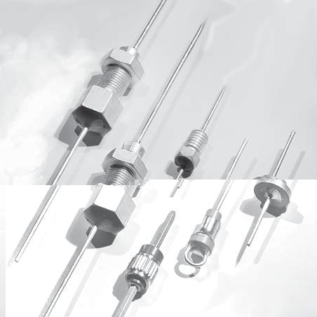
117
118 Durchführungskondensatoren Feedthrough capacitors Inhaltsverzeichnis / Contents Seite / Page Allgemeines General Information Durchführungskondensatoren mit Anschlußdraht Feedthrough capacitors with pin Durchführungskondensatoren ohne Anschlußdraht Feedthrough capacitors without pin Zertifiziertes QM-System: ISO/TS 16949:2002 ISO 9001:2000 Certified QM-System: ISO/TS 16949:2002 ISO 9001:
119 Allgemeines General Information Hochfrequenzverstärker, z. B. Antennenverstärker, FM-, VHF-, UHF-Tuner und Oszillatoren werden vorwiegend in Metallgehäuse eingebaut, damit hochfrequente Störstrahlungen vermieden werden. Zur Einführung der spannungsführenden Leitungen in das Metallgehäuse bietet SUMDIA keramische Durchführungskondensatoren in den verschiedensten Bauformen an. Hochintegrierte Bauelemente und elektronische Schaltungen sind in hohem Maße anfällig für Fehlfunktionen durch elektromagnetische Störeinflüsse. Deshalb sind immer umfangreichere Maßnahmen zur Störspannungsunterdrückung notwendig. Eine wirksame Methode, diese Störungen abzufangen, ist z. B. der Einsatz von Steckverbindern mit Durchführungskondensatoren der Ausführungen DEEQ und BEEQ. Die wichtigsten Merkmale des SUMIDA-Durchführungskondensatoren-Programmes sind: Großes Kapazitätsspektrum Kleine Eigeninduktivität Hohe Dämpfung für Frequenzen bis 3 GHz Umfangreiches Typenprogramm Kleinste Abmessungen Widerstandsfähigkeit gegen Spannungsimpulse Die wesentlichsten Anwendungsgebiete liegen in der: Unterhaltungselektronik Büro- und Datentechnik Telekommunikation Luftfahrt-Technik Automobil-Elektronik Industrie-Elektronik Kondensator-Keramik Siehe Teil: Keramik-Festkondensatoren High-frequency amplifiers, e.g. antenna amplifiers, FM- VHF-, UHF-tuners and oscillators are mostly built into metal housings in order to avoid spurious radiation. For insertion of the current lines into the metal housing SUMIDA offers ceramic feedthrough capacitors in many different styles. High-integrated components and electronic circuits are very susceptible to malfunction due to electro-magnetic interference. Therefore more and more comprehensive measures to suppress interference voltages are necessary. An effective method to intercept these interferences is e.g. the application of connectors with feedthrough capacitors styles DEEQ and BEEQ. The most important properties of the SUMIDA-feedthrough capacitor programme are the following: Wide capacitance range Low self-inductance High attenuation for frequencies up to 3 GHz Extensive style programme Smallest dimensions Resistibility to voltage impulses The main application areas are: Entertainment electronics Office and data processing Telecommunications Aeronautics technics Automotive electronics Industrial electronics Capacitor Ceramics See part: Ceramic Fixed Capacitors
120 Einbauhinweise Mounting Instructions Für Lötanschluß in der metallisierten Innenbohrung: Bauart BEBQ For soldering connection into metallized bore-hole: type BEBQ Für Steckanschluß: Bauart BDBQ mit Innenleiter ø 1.3 mm For plug-in connection: type BDBQ with pin ø 1.3 mm Für PCB-Montage: Bauart BDBQ mit Innenleiter ø 0.7 mm oder ø 1.0 mm For PCB mounting: type BDBQ with pin ø 0.7 mm or ø 1.0 mm Für Steckermontage: Bauarten DEEQ und BEEQ For plug-in mounting: types DEEQ and BEEQ Werkstoff des Innenleiters: Elektrolytkupferdraht (E-Cu 58 DIN 1787 Reinzinn) Material of the pin: Electrolytic copper wire (E-Cu 58 DIN 1787 pure tin)
121 Löthinweise Keramik ist ein temperaturwechselempfindliches Material. Die Temperatur an der Lötstelle sollte daher so niedrig wie möglich gehalten werden. Sie darf auf keinen Fall 260 C überschreiten. Zur Vermeidung von Lötrissen in der Keramik muß darauf geachtet werden, dass kein plötzlicher Temperaturwechsel eintritt, d.h. Vorwärmen ist ratsam und nach dem Löten langsam Abkühlen, hierbei ist jeglicher Luftzug zu vermeiden. Dies betrifft vor allen Dingen Kondensatoren der Klasse 2. Alle Durchführungskondensatoren in tauchbeloteter Ausführung (BUBQ, BEBQ, BDBQ) haben genügend Lotreserve (Lot Sn 99,3/Cu 0,7) und können ohne zusätzliche Lotzufuhr gelötet werden (Bild 1). Bei allen unbeloteten Ausführungen (BEEQ, LUEQ, LDEQ, LEEQ, DEEQ) ist für ausreichende Zinnzufuhr durch dosierte Lotpaste oder durch Lotring zu sorgen. Für die Verarbeitung und Lötung von Durchführungskondensatoren der Baureihe 2710 und 2720 (z.b. für gefilterte Steckverbinder) wird eine Lötung wie im Bild 2 empfohlen. Fluxen wird in jedem Fall empfohlen. Soldering Instructions Ceramic material is very sensitive to changes in temperature. The temperature at the soldering point should therefore be kept as low as possible and should in no case exceed 260 C. To avoid soldering cracks in the ceramic it must be ensured that there is no sudden change in temperature, that means preheating should be carried out and after soldering, the part allowed to cool slowly, avoiding any draught. This applies especially to capacitors of class 2. All feedthrough capacitors in tin-dipped style (BUBQ, BEBQ, BDBQ) have sufficient solder reserve (solder Sn 99,3/Cu 0,7) and can therefore be soldered without additional solder (Fig. 1). Care must be taken that there is a sufficient tin supply for all unsoldered styles (BEEQ, LUEQ, LDEQ, LEEQ, DEEQ) by dosed solder paste or a solder ring. Soldering according to figure 2 is recommended for processing and soldering of feedthrough capacitors of series 2710 and 2720 (e.g. for filtered connectors) Flux is recommended in all cases. Bild 1: Fig. 1: Bild 2: Fig. 2:
122 Lötmethoden und Lötzeit Kolbenlötung: Für die Kolbenlötung wird ein temperaturgeregelter Lötkolben empfohlen. Eine Spitzentemperatur von 260 C sollte nicht überschritten werden. Schwalllötung: Beim Schwalllöten hat sich die Doppelwelle bewährt. Die erste turbulente Welle umspült und verlötet das Bauelement. Die zweite Laminarwelle entfernt das überflüssige Zinn. Die Badtemperatur ist vom jeweiligen Lötmedium abhängig. Reflow-Lötung: Die Erwärmung erfolgt mittels IR-Strahlung, Heizplatte oder Heißluft. Soldering methods and soldering time Soldering iron: A temperature-controlled soldering iron is recommended. A peak temperature of 260 C should not be exceeded. Flow soldering: As to flow soldering the double wave is a proved method. The first turbulent wave washes around the component and solders it. The second laminary wave removes the superfluous tin. The solder bath temperature is depending on the respective soldering medium. Reflow soldering: Heating is made by means of infra-red radiation, hotplate or hot-air Typical Reflow - Soldering Profil (depending on used solder paste) soldering MA X min 200 end ramp 217 t max 90sec 217 temperatuer C preheat anneal opening ramp 20 solder paste Sn96Ag time in sec 25 Dampfphasenlötung: Hier wird der physikalische Effekt des Kondensierens einer Flüssigkeit unter Abgabe von Wärme ausgenutzt. Die Löttemperatur wird ausschließlich durch die Siedetemperatur der Flüssigkeit bestimmt. Vapour phase soldering: Vapour phase soldering uses the physical effect of condensing a liquid by emission of heat. The soldering temperature is solely determined by the boiling temperature of the liquid. Reinigen Nach dem Löten der Kondensatoren sollte ein Waschvorgang mit einem handelsüblichen Reinigungsmittel oder in einem Ultraschallbad erfolgen. Dabei ist zu beachten, daß schockartige Temperaturbelastungen mit Temperaturdifferenzen größer 100 C vermieden werden. Cleaning: After the capacitors are soldered, they should be cleaned with a customary cleaning agent or in an ultrasonic bath. Temperature shocks with temperature differences of more than 100 C should be avoided
123 Resonanzfrequenz Resonance Frequency Die Resonanzfrequenz von Keramik-Durchführungskondensatoren hängt ab von der Keramik sowie der Bauart. f res = c 2L The resonance frequency of ceramic feedthrough capacitors depends on the ceramic as well as on their style. 1 ε c = Lichtgeschwindigkeit im Vakuum ( 3,0 x 10⁸ m / sec) L = Länge des Durchführungskondensators ε = Dielektrizitätskonstante der Keramik Dämpfung: Typischer Verlauf der Dämpfung in Abhängigkeit von der Frequenz bei Durchführungskondensatoren mit verschiedenen Kapazitätswerten, gemessen im 50 Ohm-System. c = velocity of light in vacuum (3,0 x 10⁸ m / sec) L = lengths of feedthrough capacitors ε = dielectric constant of ceramic Attenuation: Typical characteristic of attenuation dependant on frequency of feedthrough capacitors with different capacitance values, measured in 50 Ohm system. Meßanordnung Measuring technique
124 Dämpfungskurve Durchführungskondensatoren Bauart BDBQ (typische Kurven) Attenuation curve of feedthrough capacitors style BDBQ (typical curves) 1 = BDBQ pf 3 = BDBQ pf 2 = BDBQ pf 4 = BDBQ pf (Sonderausführung special type) Dämpfungskurve Durchführungskondensatoren Bauart DEEQ (typische Kurven) Attenuation curve of feedthrough capacitors style DEEQ (typical curves) 1 = DEEQ 2,4 x 2,0 330 pf 3 = DEEQ 2,4 x 2, pf 2 = DEEQ 2,4 x 2, pf 4 = DEEQ 2,0 x 3, pf Die Dämpfung im Durchlaßbereich hängt von der Keramikart ab. The attenuation in the transmission area depends on the ceramic type
125 Stromimpulsprüfungen an Durchführungskondensatoren gemäß DIN VDE 0839 / 0846 / 0847 Anschlüsse mit Epoxid vergossen 1. Festigkeit gegen Prüfimpuls 1.2 µs/50 µs Current impulse tests with Feedthrough Capacitors acc. to DIN VDE 0839 / 0846 / 0847 connections potted with epoxide 1. Stability to test impulse 1.2 µ/50µs Typ / Style U kø U kmin U kmax in kv DEEQ 1,6 x 0,88 x 2,8 2,93 2,58 3,28 DEEQ 1,8 x 1,0 x 2,8 4,19 3,81 4,57 DEEQ 2,4 x 1,65 x 2,8 4,19 3,81 4,57 2. Festigkeit gegen Burstsignal 5 ns/50 ns 2. Stability to burst signal 5 ns/ 50ns Typ / Style U kø U kmin U kmax in kv DEEQ 1,6 x 0,88 x 2,8 > 4 3,9 > 4 DEEQ 1,8 x 1,0 x 2,8 > 4 > 4 > 4 DEEQ 2,4 x 1,65 x 2,8 3,8 3,5 > 4 Nennstrom und Nennleistung Rated current and rated power Nenngröße Rated size (mm) Max. zul. Strom Max. perm. current (A) Max. zul. Verlustleistung Max. permissible leakage power (MW) Max. zul. Blindleistung bei einem Verlustwinkel tan d in 10-3 Max. permissible reactive power at a loss angle tan d of 10-3 (VA) 0, Rohrkondensatoren Ø x Länge / tubular capacitors Ø x length 1,7 x 7 0, ,5 1,0 0,6 0,4 2 x 7 0, ,0 1,3 0,8 0,6 3 x 11 0, ,5 3,0 1,8 1,3 Durchführungskondensatoren / Feedthrough capacitors Ø 5 0, ,5 8,5 5,0 3,6 Ø 6 0, ,0 10,0 6,0 4,3 Höchster zulässiger Strom für den Durchführungsleiter bei Drahtdurchmesser: 0,7 mm: 4A 1,0 mm: 6A Weitere Angaben über: - Betriebsbedingungen und Eigenschaften - Mess- und Prüfbedingungen Siehe Teil: Keramik-Festkondensatoren Maximum permissible current for the center wire with lead diameter: 0,7 mm: 4A 1,0 mm: 6A Further information about: - operating conditions and characteristics - measuring and test conditions See Part: Ceramic Fixed Capacitors
126 Kennbuchstaben für Durchführungskondensatoren Code letters for Feedthrough Capacitors Kennbuchstaben in alphabet. Reihenfolge Code letters in alphabetical order 1. Kennbuchstabe 1. Code Letter Körperform Size 2. Kennbuchstabe 2. Code Letter Art der Durchführungsleiter Type of center lead 3. Kennbuchstabe 3. Code Letter Art der Außenbefestigung Type of Outer Mounting 4. Kennbuchstabe 4. Code Letter Oberfläche Surface B Buchse mit Bund Sleeve with collar beloteter Belag soldered electrode beloteter Belag soldered electrode - D Rohr Tube Drähte gestreckt streched leads - - E - unbeloteter Belag unsoldered termination unbeloteter Belag unsoldered termination - F - Lötfahnen oder Ösen soldering lug or eyelet - - L Lochscheibe Hole disc - metallische Lotscheibe metallic soldering disc vollständig lackiert completely lacquered M - - N - - Gewinde mit Bund thread with collar metallische Lötbuchse metallic soldering bushing teilweise lackiert partially lacquered teilweise umhüllt partially coated Q unlackiert unlacquered U - Draht u. runde Öse wire and round eyelet - vollständig umhüllt completely coated V - Draht u. ovale Öse Wire and oval eyelet - - Z Sonderausführung Special style Sonderausführung Special style Sonderausführung Special style Sonderausführung Special style
127 BDBQ 3-01 Baureihe 2709 BDBQ 3-01 Series 2709 Der Durchführungsleiter ist in Pfeilrichtung gegen Durchrutschen gesichert. The centre wire is protected against sliding through in the direction of the arrow. Klasse 1 / Class 1 Klasse 2 / Class 2 Bauart Style BDBQ 3-01 BDBQ 3-01 Nennspannung Rated voltage 160 V DC 160 V DC Prüfspannung Test voltage 320 V DC 320 V DC Verlustfaktor tan δ C = pf < 2 (15/C +0,7)x10-3 <35x10-3 Dissipation factor tan δ C > 50 pf: < 2 x 10⁻³ (2,5 x 10⁻³ for N2200) Der Verlustfaktor für Kapazitätswerte < 5 pf wird nur für die verwendete Keramikart garantiert. The dissipation factor for capacitance values < 5 pf is guaranteed for ceramic material used only. Isolationswiderstand Insulation restistance Ris > Ω Ris > 3 x 10 9 Ω IEC Temp. - Koeff. bzw. Char. IEC temp. coeff. or char. NP0 2E4 Prüfklasse Climatic category 25/085/04 25/085/04 Zulässiger Betriebstemperaturbereich Permissible operating temperature range -25 C C -25 C C Oberfläche Surface Kennzeichnung Marking unlackiert unlacquered entfällt none unlackiert unlacquered entfällt none Bestellbeispiel / Ordering example: 2709 BDBQ pf /+80-20% 2E4 160 V DC
128 Kapazitätswerte - Abmessungen BDBQ 3-01 Baureihe 2709 Capacitance Value - Dimensions BDBQ 3-01 Series 2709 C-Wert C-Value [pf] Baugröße Size [D x L] Baugröße Size [D x L] Klasse 1B / Class 1B Klasse 2 / Class 2 4,7 3 x 5-5,6 3 x x x x x 5 Kapazitätstoleranzen BDBQ 3-01 Baureihe 2709 Capacitance Tolerances BDBQ 3-01 Series 2709 Keramik Ceramic NP0 Kapazitätstoleranzen Capacitance Tolerances 0,5 pf 1 pf 2E % (D 6000) %
129 BUBQ 5-00, BDBQ 5-02, BDBQ 5-00 (5-12) Baureihe 2701 BDBQ 5-00, BDBQ5-02, BDBQ 5-00 (5-12) Series 2701 BDBQ 5-12 BDBQ 5-00 BDBQ 5-02 BUBQ Der Durchführungsleiter ist in Pfeilrichtung gegen Durchrutschen gesichert. The centre wire is protected against sliding through in the direction of the arrow.
130 Bauart Style Klasse 1 Class 1 BUBQ 5-00, BDBQ 5-02, BDBQ 5-00 (5-12) Klasse 2 Class 2 BUBQ 5-00, BDBQ 5-02, BDBQ 5-00 (5-12) Nennspannung Rated voltage 400 V DC 400 V DC Prüfspannung Test voltage 800 V DC 800 V DC Verlustfakor tan δ C = pf < 2 (15/C +0,7)x10-3 <35x10-3 Dissipation factor tan δ C > 50 pf: < 2 x 10⁻³ (2,5 x 10⁻³ for N2200) Der Verlustfaktor für Kapazitätswerte < 5 pf wird nur für die verwendete Keramikart garantiert The dissipation factor for capacitance values < 5 pf is guaranteed for ceramic material used only. Isolationswiderstand Insulation resistance Ris > Ω Ris > 3 x 10 9 Ω IEC Temp. - Koeff. bzw. Char. IEC temp. coeff. or char. P100, NP0, N470, N1500, N2200 2B4, 2C4, 2E4, 2F4 Prüfklasse Climatic category 25/085/04 25/085/04 Zulässiger Betriebstemperaturbereich Permissible operating temperature range -25 C C -25 C C Oberfläche Surface Kennzeichnung Marking unlackiert unlacquered entfällt none unlackiert unlacquered entfällt none Bestellbeispiel / Ordering example: 2701 BDBQ pf / 10% 1B 160 V DC
131 Kapazitätswerte - Abmessungen Baureihe 2701 Capacitance Value - Dimensions Series 2701 C-Wert C-Value [pf] Baugröße Size [D x L] P100 NP0 N470 N750 N1500 N2200 2B4 (D900) 2C4 D2000) 2E4 (D6000) 2F4 (D9000) 1,5 4,5 x 6 1,8 4,5 x 6 2,2 4,5 x 6 2,7 4,5 x 7,5 3,3 4,5 x 7,5 3,9 4,5 x 7,5 4,5 x 6 4,7 4,5 x 7,5 4,5 x 6 5,6 4,5 x 7,5 4,5 x 7,5 6,8 4,5 x 7,5 8,2 4,5 x 7,5 10 4,5 x 7,5 12 4,5 x 7,5 15 4,5 x 7,5 4,5 x ,5 x 7,5 22 4,5 x ,5 x 7,5 33 4,5 x 7,5 39 4,5 x ,5 x 7,5 56 4,5 x 7,5 68 4,5 x 8,5 82 4,5 x 7, ,5 x 7, ,5 x ,5 x 7, ,5 x 7, ,5 x 7, ,5 x 7, ,5 x 7, ,5 x ,5 x ,5 x ,5 x 7, ,5 x 7, ,5 x 8,5 4,5 x ,5 x 6, ,5 x 8,
132 Kapazitätstoleranzen Baureihe 2701 Capacitance Tolerances Series 2701 Keramik Ceramic P N B4 (D900) Kapazitätswerte Capacitance Values Kapazitätstoleranzen Capacitance tolerances <10 pf ±0,5 pf ±1 pf >10 pf ±10 % ±20 % alle Werte all values ±20 % % % 2C4 / 2E4 (D2000 / D6000) 2F4 (D9000) alle Werte all values alle Werte all values % % % %
133 LUEQ 6-01, LDEQ 6-01 Baureihe 2703 LUEQ 6-01, LDEQ 6-01 Series 2703
134
135 DDMN 1,7-00, Baureihe 2706 DDMN 1,7-00, Series 2706 Zulässiges Anzugsdrehmoment 50Ncm. Besondere Merkmale: - Miniaturbauform - Bruchsicher Permissible starting torque 50 Ncm. Special features: - Miniature Style - Unbreakable Klasse 1 Class 1 Klasse 2 Class 2 Bauart Style DDMN 1,7-00 DDMN 1,7-00 Nennspannung Rated voltage 63 V DC 63 V DC Prüfspannung Test voltage 320 V DC 320 V DC Verlustfaktor tan δ Dissipation factor tan δ <1,5 x 10⁻³ < 25 x 10-3 Isolationswiderstand Insulation resistance Ris > Ris > 3 x 10 9 IEC Temp. - Koeff. bzw. Char. IEC temp. coeff. or char. N750, N1500 2B2, 2C2, 2E2, 2F2 Prüfklasse Climatic category 55/085/21 55/085/21 Zulässiger Betriebstemperaturbereich Permissible operating temperature range -55 C C -55 C C Gewindeanschluß Threaded connector Kennzeichnung Marking versilbert silvered entfällt none versilbert silvered entfällt none Bestellbeispiel / Ordering example: 2706 DDMN 1, pf / % 2D3 63 V DC
136 Kapazitätswerte - Abmessungen Baureihe 2706 Capacitance Value - Dimensions Series 2706 Baugröße / Size [D x L] C-Wert C-Value [pf] Klasse 1B Class 1B Klasse 1F Class 1F Klasse 2 Class 2 N750 N1500 2B2 (D900) 2C2 (D2000) 2E2 (D3500) 2F2 (D6000) 47 1,7 x ,7 x ,7 x ,7 x ,7 x ,7 x ,7 x ,7 x ,7 x ,7 x ,7 x ,7 x ,7 x ,7 x ,7 x ,7 x 7 Kapazitätstoleranzen Baureihe 2706 Capacitance Tolerances Series 2706 Keramik Ceramic N750 / N1500 ±10 % Kapazitätstoleranzen Capacitance Tolerances 2B2 (D900) ±20 % % 2C2 / 2E2 / 2F2 / (D2000 / D3500 / D6000) % %
137 DDMZ 3-00, Baureihe 2705 DDMZ 3-00, Series 2705 Die Befestigungsmutter wird lose mitgeliefert. Zulässiges Anzugsdrehmoment 120 Ncm. Besondere Merkmale: - bruchsicheres Gehäuse - Hohe Feuchtigkeitsbeständigkeit Nut is supplied in bulk. Permissible starting torque 120 Ncm. Special features: - Unbreakable housing - moisture resistance Klasse 1 Class 1 Klasse 2 Class 2 Bauart Style DDMZ 3-00 DDMZ 3-00 Nennspannung Rated voltage 500 V DC 500 V DC Prüfspannung Test voltage 1250 V DC 1250 V DC Verlustfaktor tan δ Dissipation factor tan δ C = pf: < 1,5 (15/C +0,7) x 10-3 < 25 x 10-3 C > 50 pf: < 1,5 x 10⁻³ Isolationswiderstand Insulation resistance R is > Ω R is > 3 x 10 9 Ω IEC Temp. - Koeff. bzw. Char. IEC temp. coeff. or char. N150, N470, N750, N1500 2B2, 2D2, 2F2 Prüfklasse Climatic category 55/085/56 55/085/56 Zulässiger Betriebstemperaturbereich Permissible operating temperature range -55 C C -55 C C Oberfläche Surface Kennzeichnung Marking bruchsicher kunststoffvergossen Kapazitätswert, Keramik capacitance value, ceramic bruchsicher kunststoffvergossen Kapazitätswert, Keramik capacitance value, ceramic Bestellbeispiel / Ordering example: 2705 DDMZ pf / +10% N150 / 1B 500 V
138 Kapazitätswerte - Abmessungen Baureihe 2705 Capacitance Values - Dimensions Series 2705 Baugröße Size [D x L] C-Wert C-Value [pf] Klasse 1B Class 1B Klasse 1F Class 1F Klasse 2 Class 2 N150 N470 N750 N1500 2B2 (D900) 2C2 (D2000) 2F2 (D6000) 47 3 x x x x x x x x x x x x x x 16 Kapazitätstoleranzen Baureihe 2705 Capacitance Tolerances Series 2705 Keramik Ceramic Kapazitätstoleranzen Capacitance Tolerances N N1500 ±10 % ±20 % 2B2 (D900) ±20 % % 2C2 / 2F2 (D2000 / D6000) % %
139 Baureihe 2709 BEEQ 3-01 Series 2709 BEEQ 3-01 Klasse 1 Class 1 Klasse 2 Class 2 Bauart Style BEEQ 3-01 BEEQ 3-01 Nennspannung Rated voltage 160 V DC 160 V DC Prüfspannung Test voltage 320 V DC 320 V DC Verlustfaktor tan ð Dissipation factor tan ð C = pf < 2 (15/C +0,7)x10-3 C > 50 pf: < 2 x 10⁻³ Der Verlustfaktor für Kapazitätswerte < 5 pf wird nur für die verwendete Keramikart verwendet. <35x10-3 The dissipation factor for capacitance values < 5 pf is guaranteed for ceramic material used only. Isolationswiderstand Insulation resistance R is > Ω R is > 3 x 10 9 Ω IEC Temp. - Koeff. bzw. Char. IEC temp. coeff. or char. NP0 2E4 Prüfklasse Climatic category 25/085/04 25/085/04 Zulässiger Betriebstemperaturbereich Permissible operating temperature range -25 C C -25 C C Oberfläche Surface Kennzeichnung Marking unlackiert unlacquered entfällt none unlackiert unlacquered entfällt none Bestellbeispiel / Ordering example: 2709 BEEQ pf / % 2E4 160 V DC
140 Kapazitätswerte - Abmessungen Baureihe 2709 BEEQ 3-01 Capacitance Values - Dimensions Series 2709 BEEQ 3-01 Baugröße Size [D x L] C-Wert C-Value [pf] Klasse 1B Class 1B Klasse 2 Class 2 NP0 2E4 (D6000) 4,7 3 x 5 5,6 3 x x x x x 5 Kapazitätstoleranzen Baureihe 2709 BEEQ 3-01 Capacitance Tolerances Series 2709 BEEQ 3-01 Keramik Ceramic NP0 2E4 (D 6000) Kapazitätstoleranzen Capacitance Tolerances ±0,5 pf ±1 pf % % %
141 Baureihe 2701 BEBQ 5-00, BEEQ 5-00 Series 2701 BEBQ 5-00, BEEQ 5-00 Bauart Style Klasse 1 Class 1 BEBQ 5-00, BEEQ 5-00 Klasse 2 Class 2 BEBQ 5-00, BEEQ 5-00 Nennspannung Rated voltage 400 V DC 400 V DC Prüfspannung Test voltage 800 V DC 800 V DC Verlustfaktor tan ð Dissipation factor tan ð C = pf < 2 (15/C +0,7)x10-3 C > 50 pf: < 2 x 10⁻³ (< 2,5 x 10⁻³ bei N2200 u. N4700) Der Verlustfaktor für Kapazitätswerte < 5 pf wird nur für die verwendete Keramikart verwendet. <35x10-3 The dissipation factor for capacitance values < 5 pf is guaranteed for ceramic material used only. Isolationswiderstand Insulation resistance R is > Ω R is > 3 x 10 9 Ω IEC Temp. - Koeff. bzw. Char. IEC temp. coeff. or char. P100, NP0, N470, N750, N1500, N2200, N4700 2B4, 2C4, 2E4, 2F4 Prüfklasse Climatic category 25/085/04 25/085/04 Zulässiger Betriebstemperaturbereich Permissible operating temperature range -25 C C -25 C C Oberfläche Surface Kennzeichnung Marking unlackiert unlacquered entfällt none Bestellbeispiel / Ordering example: 2701 BEBQ pf / ±20 % N750 1B 160 V DC unlackiert unlacquered entfällt none
142 Kapazitätswerte - Abmessungen Baureihe 2701 BEBQ 5-00, BEEQ 5-00 Capacitance Values - Dimensions Series 2701 BEBQ 5-00, BEEQ 5-00 C-Wert C-Value [pf] Klasse 1B Class 1B Baugröße Size [D x L] mm Klasse 1F Class 1F P100 NP0 N470 N750 N1500 N2200 N4700 2B4 (D900) 1,8 4,5 x 6 2,2 4,5 x 6 2,7 4,5 x 7,5 3,3 4,5 x 7,5 3,9 4,5 x 7,5 4,7 4,5 x 7,5 4,5 x 6 5,6 4,5 x 7,5 4,5 x 7,5 6,8 4,5 x 7,5 8,2 4,5 x 7,5 10 4,5 x 7,5 12 4,5 x 7,5 15 4,5 x 7,5 4,5 x ,5 x 7,5 22 4,5 x 7,5 4,5 x ,5 x 7,5 33 4,5 x 7,5 39 4,5 x 7,5 4,5 x ,5 x 7,5 56 4,5 x 7,5 68 4,5 x 7,5 82 4,5 x 7, ,5 x 7, ,5 x 7, ,5 x 7, ,5 x ,5 x 7, ,5 x 7,5 2C4 (D2000) Klasse 2 Class 2 2E4 (D6000) 2F4 (D9000) 390 4,5 x 7, ,5 x 7, ,5 x 7, ,5 x ,5 x ,5 x ,5 x 7, ,5 x 7, ,5 x 7,5 4,5 x
143 Kapazitätstoleranzen Baureihe 2701 BEBQ 5-00, BEEQ 5-00 Capacitance Tolerances Series 2701 BEBQ 5-00, BEEQ 5-00 Keramik Ceramic P N4700 2B4 (D900) 2C4/2E4 (D2000 / D6000) 2F4 (D9000) Kapazitätswert Capacitance value < 10 pf > 10 pf alle Werte all values alle Werte all values alle Werte all values Kapazitätstoleranzen Capacitance Tolerances ±0,5 pf ±1 pf ±10 % ±20 % ±20% % % % % %
144
145 Baureihe 2702 BEBQ 6-00, BEEQ 6-00 Series 2702 BEBQ 6-00, BEEQ 6-00 x weicht ab bei Sonderx x x weicht ab bei Sonder- Bauart Style Klasse 1 Class 1 BEBQ 6-00, BEEQ 6-00 Klasse 2 Class 2 BEBQ 6-00, BEEQ 6-00 Nennspannung Rated voltage 400 V DC 400 V DC Prüfspannung Test voltage 800 V DC 800 V DC Verlustfaktor tan ð Dissipation factor tan ð C = pf: < 2 (15/C +0,7)x10-3 C > 50 pf: < 2 x 10⁻³ Der Verlustfaktor für Kapazitätswerte < 5 pf wird nur für die verwendete Keramikart verwendet. <35x10-3 The dissipation factor for capacitance values < 5 pf is guaranteed for ceramic material used only. Isolationswiderstand Insulation resistance R is > Ω R is > 3 x 10 9 Ω IEC Temp. - Koeff. bzw. Char. IEC temp. coeff. or char. P100, NP0, N470, N750, N1500 2B4, 2C4, 2E4, 2F4 Prüfklasse Climatic category 25/085/04 25/085/04 Zulässiger Betriebstemperaturbereich Permissible operating temperature range -25 C C -25 C C Oberfläche Surface Kennzeichnung Marking unlackiert unlacquered entfällt none unlackiert unlacquered entfällt none Bestellbeispiel / Ordering example: 2702 BEBQ pf / ±20 % N750 1B 160 V DC
146 Kapazitätswerte - Abmessungen Baureihe 2702 BEBQ 6-00, BEEQ 6-00 Capacitance Values - Dimensions Series 2702 BEBQ 6-00, BEEQ 6-00 C-Wert C-Value [pf] Klasse 1B Class 1B Klasse 1F Class 1F Baugröße Size [D x L] mm Klasse 2 Class 2 P100 NP0 N470 N750 N1500 2B4 (D900) 2C4 (D2000) 2E4 (D6000) 2F4 (D9000) 4,7 6 x 6,5 5,6 6 x 6,5 6,8 6 x 6,5 8,2 6 x 6, x 6, x 6, x 6, x 6, x 6, x 6, x 6, x 6, x 6, x 6, x 6, x 6, x 6, x 6, x 6, x 6, x 6, x 6, x 7 6 x 6, x 6, x 6, x 8, x 8, x 8, x 8, x 8,5 6 x 8, x 8,
147 Kapazitätstoleranzen Baureihe 2702 BEBQ 6-00, BEEQ 6-00 Capacitance Tolerances Series 2702 BEBQ 6-00, BEEQ 6-00 Keramik Ceramic P N1500 2B4 (D900) Kapazitätswert Capacitance value < 10 pf > 10 pf alle Werte all values Kapazitätstoleranzen Capacitance Tolerances ±0,5 pf ±1 pf ±10% ±20% ±20% % 2C4/2E4 (D2000 / D6000) alle Werte all values % % 2F4 (D9000) alle Werte all values % %
148 Baureihe 2704 LEEQ 6-00 Series 2704 LEEQ 6-00 Klasse 2 Class 2 Bauart Style LEEQ 6-00 Nennspannung Rated voltage 50 V DC (30 V DC) Prüfspannung Test voltage 100 V DC (60 V DC) Kapazität Capacitance 1000 pf * Kapazitätstoleranz Capacitance Tolerance % / % Verlustfaktor tan ð Dissipation factor tan ð <35 x 10-3 Isolationswiderstand Insulation resistance R is > 3 x 10 9 IEC Temp. - Koeff. bzw. Char. IEC temp. coeff. or char. 2E4 (D6000) Prüfklasse Climatic category 25/085/04 Zulässiger Betriebstemperaturbereich Permissible operating temperature range -25 C C Oberfläche Surface Kennzeichnung Marking unlackiert unlacquered entfällt none * auch in anderen Kapazitätn erhältlich. / Also available in other capacitance. Bestellbeispiel / Ordering example: 2704 LEEQ pf / % 2E4 40 V DC
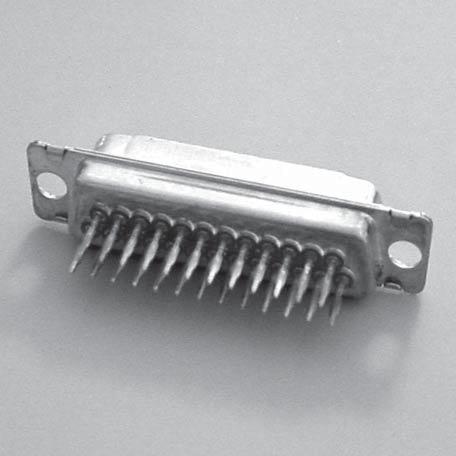
149
150
151 Durchführungskondensatoren für Steckverbinder In elektrischen Anlagen, Fahrzeugen, Maschinen und Geräten entstehen aus verschiedenen Gründen hochfrequente Störspannungen. Abhängig von ihrer Frequenz breiten sie sich über Zuleitungen durch induktive oder kapazitive Kopplung sowie durch direkte Abstrahlung aus. Die Vorschriften für elektromagnetische Verträglichkeit (EMV) und Störstrahlsicherheit müssen, da immer komplexere integrierte Schaltungen wie z. B. Mikroprozessoren zum Einsatz kommen, zwangsläufig eingeengt werden. Dies gilt für alle Bereiche der Kfz-Elektronik, der Büro- und Datentechnik, der Telekommunikation, der Luftfahrttechnik, der Industrie- und Unterhaltungselektronik. In den meisten Fällen läßt sich das Auftreten hochfrequenter Störspannungen nicht verhindern. Neben optimierter Kabelführung ist es notwendig, Leitungen, auf denen sensitive Signale verarbeitet werden, mit geeigneten Abschirmmaßnahmen zu entstören und dadurch sauber zu halten. Eine dieser Maßnahmen ist der Einsatz von geschirmten Steckverbindern, wobei die einzelnen Pins der Steckverbinder mit Kondensatoren direkt beschaltet sind und die Störimpulse direkt über die Kondensatoren gegen Masse abgeleitet werden. Durch diese Beschaltung wird eine hohe Geräuschpegelunterdrückung für Frequenzen bis zu 3 GHz erzielt. Ein weiterer Vorteil liegt in dem ausgezeichneten Preis- / Leistungsverhältnis. Feedthrough Capacitors for Connectors High-frequency interferences arise from various sources in all electric and electronic equipment, in vehicles, machines and devices. Depending on their frequency they propagate through feed lines as well by inductive or capacitive coupling or by direct radiation. The regulations concerning electromagnetic compatibility (EMC) and interference (EMI) have inevitably become more restrictive as increasingly complex integrated circuits as e.g. microprocessors are being used. This is of critical importance in all areas of automotive electronics, data processing, telecommunication, avionics as well as in industrial and entertainment electronics. In most cases the occurrence of high-frequency interference is unavoidable. Besides an optimal cable run it is necessary to keep lines, where sensitive signals are processed, clean from interference by suppression or by suitable shielding measures. One of these measures is the application of shielded connectors, in which the individual pins of the connectors are directly wired with capacitors and the interference pulses are filtered through the capacitor directly to the earth. This technique yields a high suppression of noise levels in frequencies up to 3 GHz. A further advantage can be seen in the excellent price to capacity ratio. Baureihe 2710 und 2720 Entstörung im Steckverbinder Keramische Durchführungskondensatoren, aufgebaut in der Art gewöhnlicher Rohrkondensatoren oder in angelehnter Bauform, können aus einer Vielzahl von dielektrischen Materialien hergestellt werden. Als erfahrener Hersteller keramischer Materialien produziert SUMIDA eine Palette von Werkstoffen mit verschiedenen Dielektrizitätskonstanten bei unterschiedlichem Temperaturverhalten, mit denen die gewünschten Kapazitätswerte und damit Dämpfungscharakteristiken erzeugt werden können. Series 2710 and 2720 EMI protection within the connector Ceramic feedthrough capacitors designed like ordinary tubular capacitors or related designs can be produced from a variety of dielectric materials. As an experienced manufacturer of ceramic materials, SUMIDA offers a broad range of materials with different permittivities at various temperature behaviours to obtain the requested values of capacitance and therefore attenuation characteristics
152 Bild 1 zeigt einige Beispiele von Temperaturkurven prinzipiell unterschiedlicher Werkstoffe. Besondere Bedeutung erlangten, aufgrund ihrer hohen Dielektrizitätszahl von bis zu 4000, die sog. X7R-Materialien, die über den Temperaturbereich von -50 C bis zu C um nicht mehr als ±15 % ihres Kapazitätsnennwertes schwanken dürfen. Diagram 1 shows some examples of temperature curves of basically different materials. Because of their high dielectric constant of up to 4000, the so-called X7R materials are of special interest due to the fact that their capacitance value has vary not more than ±15 % over a temperature range from -50 up to +125 C X7R -20 ΔC [%] -40 N D T [ C] Abb. 1 : Typische Kapazitätsänderung als Funktion der Temperatur Um den filigranen und sehr eng tolerierten Röhrchen ihre Gestalt zu geben, kommen keramische Formgebungsverfahren wie Extrudieren oder Trockenpressen zum Einsatz. Der Werkstoff erhält dann bei einem Sinterbrand von in der Regel über 1300 C seine endgültigen Eigenschaften (Dielektrizitätskonstante, Isoliervermögen etc.). Zur Ausbildung eines Rohrkondensators werden die Keramikröhrchen als Schüttgut voll metallisiert unter Anwendung von stromlosen Metallisierungsverfahren (Nickel) und galvanischer Verstärkung (Zinn), um hinterher wieder an den Stirnflächen freigeschliffen zu werden. Durch die 4 bis 10 µm dicke Zinnschicht sind die Durchführungskondensatoren ohne Probleme mit Innenleitern und Masseblech zu verlöten. Diagr. 1 : Typical change of capacitance as a function of temperature To form the filigree and very tight tolerated tubes, ceramic forming processes like extruding and dry pressing are used. Then the material gets its final properties (dielectric constant, insulating property, etc.) by sintering at a temperature normally above 1300 C. To form a tubular capacitor the ceramic tubes are completely metallized as bulk using electroless plating (nickel) and electrodeposition (tin). Later on the frontal areas are grinded to remove the metallization. Due to the 4 to 10 µm thick tin layer the feedthrough capacitors are solderable to the inner line and to the ground plate without any problems
153 Serie 2710 und 2720 Der Durchführungskondensator erfüllt seine Filterfunktion als Tiefpaßfilter gegen Erde, mit der Aufgabe, hochfrequente Störsignale gegen Masse abzuleiten, während die niederfrequenten Nutzsignale ungedämpft übertragen werden. Ist der Abstand der Frequenzen von Nutz- und Störsignal genügend groß, so ist mit dieser einfachen Maßnahme eine klare Trennung beider Signale möglich. In der Praxis sind die Störsignale oft sehr hochfrequente Spannungspitzen und Störstrahlungen, welche somit leicht von einem elektronischen System ferngehalten werden können. Für den EMV-gerecht konstruierenden Ingenieur ergibt sich nun die Möglichkeit, durch verschiedene Kapazitätswerte die gewünschte Filtercharakteristik einzustellen. Dabei zeigt sich, daß mit Durchführungskondensatoren eine Dämpfungsgüte von bis zu 50 db (1500 pf) erreicht werden kann. Eine Kurvenschar von "Filterflanken" mit Kapazitäten von 330 pf bis 1500 pf zeigt Bild 2. Series 2710 and 2720 The feedthrough capacitor fulfils its function as a lowpass filter against earth in order to derive high-frequent noise signals against ground, whereas low-frequent information signals are transferred undamped. As long as the distance in frequency between information and noise signal is sufficient, it is possible to have a clear distinction between both signals by means of such a simple method. In practice noise signals are often very high-frequent voltage peaks and radio interferences which thereby can easily be kept away from an electronic system. There is a possibility for engineers designing acc. to EMI principles to adjust the desired filter characteristic by using different values of capacitance. It shows that with feedthrough capacitors the damping ratio of up to 50 db (1500 pf) may be reached. A set of curves of "filter characteristics" with capacitances ranging from 330 pf to 1500 pf is shown in diagram Dämpfung / Attenuation [db] pF 470pF 680pF 1000pF 1500pF Frequenz / Frequency [MHz] Abb. 2 : Dämpfungskennlinien befilterter Steckverbinder mit Durchführungskondensatoren Für den Anwender dieser im hohen Frequenzbereich sicheren Filterlösung ist die Zusammenarbeit mit dem Bauelementdesigner von entscheidender Bedeutung. So kann beispielsweise bei ungeschickter Wahl von Material und Dimension, bei ein und derselben Kapazität, eine völlig ungenügende Dämpfungskennlinie über 1 GHz erzielt werden. Der Einfluß der Eigeninduktivität, wie im Ersatzschaltbild dargestellt (Bild 3), darf bei Frequenzen um 1 GHz nicht vernachlässigt werden. Gerade im Frequenzband der heutigen (D-Netz: 900 MHz und 1,6 bis 1,8 GHz) Telekommunikation muß eine saubere Dämpfung ohne störende Eigenresonanz gewährleistet sein. Diagr. 2 : Attenuation of filtered connectors with feedthrough capacitors For the user of this in the high-frenquency range reliable filter solution it is essential to have a good cooperation with the designer of the component. For example a careless choice of material and dimension may cause an absolutely insufficient attenuation above 1 GHz with one and the some capacitance. The influence of selfinductance, as shown in the equivalent circuit diagram (diagr. 3) may not be neglected at frequencies around 1 GHz. Especially in the frequency band of nowadays (D-net 900 MHz and 1,6 to 1,8 GHz) telecommunications a proper damping without any disturbing selfresonance must be guaranteed
154 Serie 2710 und 2720 Series 2710 and 2720 Abb. 3 : Ersatzschaltbild eines realen Durchführungskondensatoren Neben der aufgezeigten Möglichkeit in Bezug auf resonanzfreie Dämpfungskurven sind mit Hilfe der kleinen Keramikröhrchen weitere Vorteile in befilterten Steckverbindern zu nutzen: - Flexibles Bestücken von Pin zu Pin: Verschiedene Filterkennlinien können verschiedenen Signalleitungen zugeordnet werden. - Hohe Spannungsfestigkeit gegen Störimpulse: Leitungsgeführte Störimpulse liegen oft im kv-bereich und werden von den Keramikröhrchen verkraftet (IEC 40792). - Einfacher Steckeraufbau: Die gut lötfähigen Keramikröhrchen lassen sich problemlos verarbeiten. - Hohe Integrationsdichte: Durch den Einsatz der Duko-C-Filter ist eine Miniaturisierung der Steckverbinder (High-Density, Micro-Sub-D) gewährleistet. Diagr. 3 : Equivalent circuit of a real feedthrough capacitors Other advantages besides the shown possibility concerning the attenuation curves free of resonance are achieved by using the small ceramic tubes in filtered connectors: - Flexible mounting from pin to pin: Different filter characteristics may be selected for different signal lines. - High voltage resistances against disturbing pulses: Disturbing pulses on the line are often ranging in the kv area and are withstood by the ceramic tubes (IEC 40792). - Simple connector design: The excellent solderable ceramic tubes can be handled without any problems. - High integration density: By using feedthrough capacitor filters a miniaturization of connectors (high-density, Micro-Sub-D) is guaranteed
155 Baureihe 2710 für Steckverbinder und andere Anwendugen BEEQ 2,6 Series 2710 for connectors and other applications BEEQ 2,6
156 Kapazitätswerte - Abmessungen Baureihe 2710 Capacitance Values - Dimensions Series 2710 Baugröße Size [D x L*] C-Wert C-Value [pf] Klasse 1 Class 1 Klasse 2 Class 2 N750 N1500 N2200 N4700 2B1 (D900) 2B1 (D1400) 2C1 (D2000) 2C1/X7R (D4000) 22 2,6 x 2,5 39 2,6 x 2,8 47 2,6 x 2,8 68 2,6 x 2, ,6 x 2, ,6 x 2, ,6 x 2, ,6 x 2, ,6 x 2, ,6 x 2, ,6 x 2, ,6 x 2, ,6 x 2,9 * L Richtwert / approx. value Kapazitätstoleranzen Baureihe 2710 Capacitance Tolerances Series 2710 Keramik Ceramic N750 - N4700 2B1 (D900 / D1400) 2C1/X7R (D2000 / D4000) Kapazitätswert Capacitance value alle Werte all values alle Werte all values alle Werte all values Kapazitätstoleranzen Capacitance Tolerances ±20 % ±20 % ±20 %

157 Baureihe 2720 für Steckverbinder und andere Anwendugen DEEQ 1,6; 2,0; 2,2; 2,4; 4,9 Series 2720 for connectors and other applications DEEQ 1,6; 2,0; 2,2; 2,4; 4,9 Klasse 1 Class 1 Klasse 2 Class 2 Bauart Style DEEQ 1,6; 2,0; 2,2; 2,4; 4,9 DEEQ 1,6; 2,0; 2,2; 2,4; 4,9 Nennspannung Rated voltage 100 V DC 100 V DC Prüfspannung Test voltage 500 V DC 500 V DC Verlustfaktor tan ð Dissipation factor tan ð < 2,5 x 10⁻³ < 25 x 10-3 Isolationswiderstand Insulation resistance R is > Ω R is > 5 x 10 9 Ω IEC Temp. - Koeff. bzw. Char. IEC temp. coeff. or char. N1500, N2200, N4700 2B1, 2C1,2E1, 2F1 Prüfklasse Climatic category 55/125/04 55/125/04 Zulässiger Betriebstemperaturbereich Permissible operating temperature range -55 C C -55 C C Oberfläche Surface Kennzeichnung Marking unlackiert unlaquered entfällt none unlackiert unlaquered entfällt none Bestellbeispiel / Ordering example: 2720 DEEQ 2,2 x 2,6 470 pf / % 2C1 100 V DC
158 Kapazitätswerte - Abmessungen Baureihe 2720 Capacitance Values - Dimensions Series 2720 C-Wert C-Value [pf] 22 2,2x1,10x2,4 33 2,4x1,10x2,4 47 Klasse 1 Class 1 Baugröße Size [D x L] N1500 N2200 N4700 2B1 (D900) 2,0x1,15x2,5 2,2x1,10x2,5 2,4x1,60x2,1 2,0x1,15x2,2 68 2,2x1,10x2, ,2x1,10x2, ,4x1,60x2,6 2,2x1,10x2,4 2B1 (D1400) Klasse 2 Class 2 2C1 (D2000) 1,6x0,90x2,5 2,0x1,15x2, ,4x1,60x2,4 2,2x1,10x2,4 4,9x3,50x2, ,9x3,50x3,2 2,4x1,60x2,2 2,2x1,10x2, ,4x1,60x2, ,4x1,60x2,8 2F1 (D6000) 1,6x0,90x2,8 2,0x1,15x2, ,2x1,10x2,85 2,4x1,60x2,20 4,9x3,50x3, ,4x1,60x2,20 2,0x1,15x2,6 4,9x3,50x2,6 2,2x1,10x3, ,4x1,60x2, ,6x0,90x3,6 Kapazitätstoleranzen Baureihe 2720 Keramik Ceramic N N4700 2B1 (D900 / D1400) 2C1/X7R (D2000 / D4000) 2F1 (D6000) Kapazitätswert Capacitance value alle Werte all values alle Werte all values alle Werte all values alle Werte all values Capacitance Tolerances Series 2720 Kapazitätstoleranzen Capacitance Tolerances ±20 % ±20 % ±20 % ±20 %
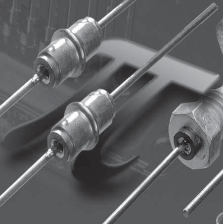
159
160 Pi-Filter BDMN 2,6 / BDNN 2,6 Pi-Filter BDMN 2,6 / BDNN 2,6 Inhaltsverzeichnis / Contents Seite / Page Allgemeines 150 General Information BDMN 2,6 Baureihe BDMN 2,6 Series 2707 Zertifiziertes QM-System: ISO/TS 16949:2002 ISO 9001:2000 Certified QM-System: ISO/TS 16949:2002 ISO 9001:
161 Allgemeines zu Pi-Filtern Anwendungsrichtlinien In Pi-Filtern sind zwei kapazitive und ein induktives Element enthalten; damit ergibt sich zur Primär- und Sekundärseite ein geringerer Eingangswiderstand. Infolge der Verwendung von 3 Elementen wird ein besseres Hochfrequenzverhalten als bei reinen L/C Kombinationen erreicht. General Information zu Pi-Filter Application guidelines Pi-Filters contain two capacitive and one inductive element resulting in low impedance to primary and secondary side (source and load). Using these 3 elements a better high frequency performance is obtained than with pure L/C combinations. Baureihe 2707 Pi-Filter BDMN 2,6, BDNN 2,6 Series 2707 Pi-Filter BDMN 2,6, BDNN 2, SW5 30 ± M ±
162 Bauart Style Klasse 1 Class 1 Pi - BDMN 2,6 Pi- DDNN 2,6 Klasse 2 Class 2 Pi - BDMN 2,6 Pi- DDNN 2,6 Nennspannung Rated voltage 100 V DC 100 V DC Prüfspannung Test voltage 250 V DC 250 V DC Verlustfaktor tan ð Dissipation factor tan ð < 2,5 x 10⁻³ < 25 x 10-3 Isolationswiderstand Insulation resistance R is > Ω R is > 5 x 10 9 Ω IEC Temp. - Koeff. bzw. Char. IEC temp. coeff. or char. N1500 2B1, 2C1, 2F4 Prüfklasse Climatic category 55/125/21 55/125/21 Zulässiger Betriebstemperaturbereich Permissible operating temperature range -55 C C -55 C C Kennzeichnung Marking entfällt none entfällt none Bestellbeispiel / Ordering example: 2707 Pi-BDMB 2, pf / % X7R 100 V DC Bestellbeispiel / Ordering example: 2707 Pi-BDNN 2, pf / % X7R 100 V DC C-Wert C-Value [pf] Kapazitätstoleranzen Capacitance Tolerances Klasse Class Einfügungsdämpfung in db Insertion loss in db 10 MHz 30 MHz 50 MHz 100 MHz 300 MHz 500 MHz 1 GHz 3 GHz 6 GHz 100 ±20 % N ±20 % 2B ±20 % 2B ±20 % 2B ±20 % 2C % 2C1/X7R % 2C1/X7R % 2F Andere Kapazitätswerte und Anschlüsse auf Anfrage. / Other capacitance values and terminations on request
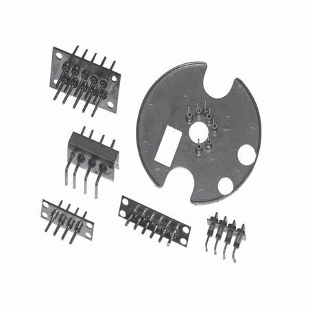
163
164 EMV-Lösungen mit Filterplatten EMI Filter Plate Assemblies Inhaltsverzeichnis / Contents Seite / Page Durchführungskondensatoren mit Pin eingelötet auf Metallplatten Feedthrough capacitors with pin - Soldered in metal plate Durchführungskondensatoren mit Pin eingelötet in PC Board Feedthrough capacitors with pin - soldered in PC board Zertifiziertes QM-System: ISO/TS 16949:2002 ISO 9001:2000 Certified QM-System: ISO/TS 16949:2002 ISO 9001:


165 Durchführungskondensatoren mit Pin - eingelötet auf Metallplatten Feedthrough capacitors with pin - soldered in metal plate Die fortschreitende Entwicklung im Telekom-Bereich, in der Automobil- und Industrieelektronik erfordert immer kleinere leistungsfähigere Komponenten, wobei neben den Bauelementekosten auch die Montagekosten verträglich sein müssen. Der Einbau von diskreten Filtern ist lohnintensiv und zeitraubend und führt auch oft zu Platzproblemen. Neue Lösungen waren gefordert mit dem Ziel, eine große Anzahl von Leitungen kostengünstig und auch platzsparend zu filtern, die Montagekosten zu senken und trotzdem für die Störprobleme einen EMV-gerechten Filter anzubieten. Hier bietet SUMIDA eine Reihe von Filterplatten an (auch nach Ihren Wünschen gefertigt), die gerade beim Einbau mehrerer Filter (auch mit unterschiedlichen Kapazitätswerten) zu diesen Kosteneinsparungen führen. The ongoing development of telecommunication, automotive and industrial electronics requires ever smaller components with ever higher efficiency. In addition to the component cost, the cost of mounting must remain at tolerable levels. The application of discrete filters is wage-intensive and time-consuming and often leads to space problems. Clients demand new solutions to filter a greater number of lines at an adequate price and a minimum use of space. They also want to reduce the mounting cost while still offering an EMI-suited filter to solve interference problems. SUMDIA offers a range of filter plates (also can be produced according to your demands) with which these cost reductions are obtained - especially complicated arrays of filters (even including different capacitance values) are required

166 Durchführungskondensatoren mit Pin - eingelötet in PC Board Feedthrough capacitors with pin - soldered in PC board Die Filterplatten können je nach Kundenwunsch gestaltet werden. Es gibt die Möglichkeit, die Kondensatoren in Metall- oder in Leiterplatten einzulöten. Abmessungen, Anzahl der Kondensatoren, verschiedene Kapazitätswerte, PIN-Durchmesser und Länge können je nach Kundenwunsch gefertigt werden. Bei den Filterplatten wird eine 100-prozentige Stückprüfung durchgeführt (Kapazität). The filter plates can be designed in accordance with customer requirements. The capacitors can be soldered onto metal or PC-boards as the client prefers. Dimensions, number of capacitors, multiple capacitance values, pin diameters and lengths can be individually determined for these custom-designed parts. A 100 % piece by piece capacitance test is carried out with the filter plates

167 Keramik-Vielschicht-Chipkondensatoren Ceramic Multilayer Chip Capacitors
168 Keramik-Vielschicht- Chipkondensatoren Ceramic Multilayer Chip Capacitors Inhaltsverzeichnis / Contents Seite / Page Allgemeine Informationen General Information Empfehlungen für die Oberflächenmontage Recommendation for Surface Mounting Prüfmethoden Test methods Zertifiziertes QM-System: ISO/TS 16949:2002 ISO 9001:2000 Certified QM-System: ISO/TS 16949:2002 ISO 9001:
169 Keramik-Vielschicht- Chipkondensatoren KEFQ - Baureihe 2535 Allgemeine Informationen ALLGEMEINES: Keramik-Multilayer-Chipkondensatoren bestehen aus bestimmten Keramischen Dielektrika - Materialien in Schichten mit dazwischenliegenden Metallelektroden. Diese Strukturen werden bei hoher Temperatur zusammengebrannt, danach werden auf den gegenüberliegenden Enden leitende Anschlüsse angebracht, um die überstehenden Elektrodenkanten zu kontaktieren. Die Anschlußmaterialien sind je nach beabsichtigter Verwendung unterschiedlich. SUMIDA bietet Keramik-Multilayer-Kondensatoren für die Oberflächenmontage (SMD) an. Die oberflächenmontierbaren Chips sind mit 2 verschiedenen Basisschichten verfügbar: Silber-Palladium- (AgPd) und Kupfer-Elektroden (Cu). Ceramic Multilayer Chip Capacitors KEFQ - Series 2535 General Information GENERAL: The ceramic multilayer chip capacitors consist of formulated ceramic dielectric materials in layers interspersed with metal electrode layers. The entire structure is fired together at high temperature, after which conductive terminations are applied on opposite ends to contact protruding electrode edges. Termination materials vary depending on the intended use. SUMIDA offers multilayer ceramic capacitors in surface mounted version (SMD). Surface mounted chips are available in 2 kinds of terminations: Silver-Palladium (AgPd) and copper electrodes (Cu). DIELEKTRISCHE TYPEN: Keramik-Multilayer-Kondensatoren werden in drei gängigen Temperatur-Charakteristiken angeboten. Sie entsprechen der internationalen Spezifikation IEC (oder aber EIA), wie das ultrastabile CG, bekannt als NP0 (C0G), das stabile 2T1 (X7R) und für allgemeine Zwecke 2F4 (Y5V). NP0 Dielektrika bestehen aus nicht-ferroelektrischen Keramikmaterialien. Dies schafft ausgezeichnete Stabilitätseigenschaften, aber eine relativ niedrige Kapazität. Beide, 2R1 (X7R) und 2F4 (Y5V) werden aus ferroelektrischen Materialien, hauptsächlich Bariumtitanat, hergestellt. NP0-Kondensatoren werden meist für Anwendungen eingesetzt, die hohe Stabilitätseigenschaften ohne Abhängigkeit von Kapazität und Verlustfaktor (tanδ) ggf. Spannung und Frequenz erfordern. Der Verlustfaktor (tanδ) ist relativ niedrig. DIELECTRIC TYPES: ceramic multilayer capacitors are offered in three most popular temperature characteristics. They are designed according to international specification IEC (or to EIA) as the ultrastable CG, known as NPO (C0G), the stable 2T1 (X7R) and for general purpose 2F4 (Y5V). NP0 dielectric is made of ceramic materials which are not ferroelectric. This yields a superior stability characteristic, but relatively low capacitance. Both 2R1 (X7R) and 2F4 (Y5V) are made from ferroelectric materials, principally barium titanate. The NP0 capacitors are used in applications which require very stable characteristics without dependence of capacitance and dissipation factor (tanδ) on time, voltage and frequency. The dissipation factor (tanδ) is relatively low
170 Kondensatoren der ferroelektrischen Typen haben nicht-lineare Temperatureigenschaften; Kapazität und tanδ werden von Temperatur, Spannung und Frequenz beeinflusst. Der Verlustfaktor ist normalerweise höher als NP0. ALTERUNG: Ferroelektrische Materialien unterliegen einer Zeitabhängigkeit, bekannt als Alterung. Man glaubt, dass diese Eigenschaft auf die Formänderungsenergie im ferroelektrischen Bereich zurückzuführen ist, die nach der Formierung stets nach Orientierung in gegenseitigem Bezug bestrebt ist. D.h. ferroelektrische Materialien unterliegen nach Abkühlung unter den Curiepunkt einer Alterung der dielektrischen Konstante logarithmisch zur Zeit. Die Alterungsrate von Kondensatoren wird in Stundendekaden ausgedrückt. 2R1 (X7R) Dielektrika z.b. altern um 2 % per Stundendekade; d.h. der Kondensator verliert 2% an Kapazität zwischen 1 und 10 Stunden nach Abkühlung und weitere 2% zwischen 10 und 100 Stunden und zusätzliche 2 % zwischen 100 und 1000 Stunden. Der Alterungsprozess von Ferroelektrika ist reversibel. Bei Erwärmen des Materials über den Curiepunkt fällt die Strukturdomäne wieder zurück auf ihren Ausgangspunkt, und der Alterungsprozess beginnt neu. Anwender sollten sich vor Augen halten, dass verschiedene Anschlußbehandlungen den Curiepunkt des Dielektrikums übersteigen und daher ein vorübergehender Anstieg der Kapazität zu erwarten ist. Die angegebene C-Toleranz des Kondensators bezieht sich auf 1000 Std. Alterung. SPANNUNGSEFFEKTE: Ferroelektrische Materialien werden auch durch die angelegte Spannung, durch beide - Gleich- und Wechselstrom - beeinflusst. Wird die Spannung in Richtung Nennspannung erhöht, fällt die Kapazität. Dieser Kapazitätsabfall ist eine Eigenschaft der dielektrischen Stärke und des Dielektrikums selbst. Dieser Kapazitätsabfall erfolgt aufgrund eines Polarisationseffekts im ferroelektrischen Material. In einem spezifischen Spannungsbereich (nahe der Durchschlagspannung) kann ein Varistoreffekt gemessen werden. FREQUENZEFFEKTE: Die Frequenz wirkt sich auf Kapazität, Verlustfaktor und Impedanz eines Kondensators aus. Erhöhte Frequenz resultiert in einem Abfall des gemessenen Kapazitätswerts und in einem Anstieg des Verlustfaktors. Dieser Effekt ist allen dielektrischen Materialien eigen, ist aber in Massen mit hoher Dielektrizitätskonstante wesentlich mehr ausgeprägt. Capacitors of the ferroelectric types have non-linear temperature characteristics; capacitance and tanδ are effected by temperature, voltage and frequency. The dissipation factor is usually higher than NP0. AGEING: Ferroelectric materials also exhibit a time dependence, known as ageing. It is believed that this behaviour is due to strain energy of the ferroelectric domains striving for orientation relative to one another after their formation. Thus, ferroelectric materials are subject to an ageing of the dielectric constant after cooling below the Curie temperature, which is logarithmic with time. The ageing rate of capacitors is expressed in terms of decade hours. 2R1 (X7R) dielectrics, for example, ages at 2 % per decade hour; i.e. the capacitors will lose 2 % capacity between 1 and 10 hours after cooling, an additional 2 % between 10 and 100 hours and an additional 2 % between 100 and 1000 hours. The ageing process of ferroelectrics is reversible. Heating the material exceeding the Curie point reverts the domains structure to its previous state and the ageing process starts again. Users should be aware that certain capacitor attachment processes exceed the Curie temperature of the dielectric and, therefore, a temporary increase in capacitance should be expected. The rated C-tolerance of capacitors is defined for 1000 hours of ageing. VOLTAGE EFFECTS: Ferroelectric materials are also affected by applied voltage, both AC and DC. As the voltage is increased towards the rated voltage, the capacitance will decrease. This decrease in capacitance is a function of dielectric thickness and dielectrics itself. This decrease in capacitance is due to a polarizing effect in the ferroelectric material. In a specific voltage range (close to the breakdown voltage) a varistor effect can be measured. FREQUENCY EFFECTS: Frequency affects capacitance, dissipation factor and impedance of capacitors. Increased frequency results in a decrease of the measured capacitance value and in an increase of the dissipation factor. The effect is common to all dielectric types, but is more pronounced in high dielectric constant formulations
171 MECHANISCHE BEANSPRUCHUNG: Dielektrische Materialien zeigen in geringem Maße Elektrostriktionen und piezoelektrische Eigenschaften. Elektrostriktion besagt, dass ein elektrisches Feld eine Veränderung bewirkt, aber eine mechanische Beanspruchung kein elektrisches Feld verursacht. Piezoelektrizität besagt, dass mechanische Beanspruchung ein elektrisches Feld ergibt und dass dieses eine Veränderung verursacht. Es ist eine Wechselverbindung. DIELEKTRISCHE ABSORPTION: Nach der Entladung wird eine Restpannung auf dem Kondensator gemessen. Hochdielektrische Materialien haben eine höhere dielektrische Absorption. CORONA: Die Ionisierung von Luft verursacht niedrigere Isolationseigenschaften auf der Kondensatoroberfläche und kann zu gegebener Zeit Ausfälle bewirken.
172 KUNDENTESTS: Infolge von Temperatur- und Spannungsabhängigkeit ist beim Erstellen einer Testreihe Vorsicht geboten. Tests der dielektrischen Festigkeit und des Isolationswiderstands werden beide mit Gleichstrom durchgeführt und senken die Kapazität; sie sollte somit vor den Spannungstests gemessen werden. Für Temperaturtests ist es empfehlenswert, dass 2R1 und 2F4 Kondensatoren vor der Kapazitätsmessung für 2 Stunden bei 125 C entaltert und für 24 Stunden bei Raumtemperatur stabilisiert werden. CUSTOMER TESTING: Because of the temperature and voltage effects, caution must be used in establishing a testing sequence. Dielectric strength and insulation resistance tests both apply DC voltage and depress capacitance, so capacitance should be measured prior to the voltage tests. For temperature tests, it is recommendable that 2R1 and 2F4 capacitors be de-aged for 2 hours at 125 C and stabilized at room temperature for 24 hours before capacitance measurements are done
173 L T Kontaktierung / Termination: Ag+gal.Ni+gal.Sn W M e g e M Abmessungen / Dimensions [mm] Baugröße / Size L W Tmax. M KEFQ ,6 ±0,15 0,80 ±0,15 0,95 0,30 ±0,15 KEFQ ,00 ±0,20 1,25 ±0,20 1,20 0,50 ±0,20 KEFQ ,20 ±0,30 1,60 ±0,20 1,50 0,60 ±0,30 KEFQ ,20 ±0,40 2,50 ±0,30 2,50 0,60 ±0,30 KEFQ ,50 ±0,50 3,20 ±0,40 3,00 0,60 ±0,30 KEFQ ,70 ±0,50 5,00 ±0,50 3,00 0,60 ±0,30 Bauart Style KEFQ Nennspannung Rated voltage 50 und/and 100 V Keramik Ceramics Kapazitätsbereich Capacitance range Kapazitätstoleranzen Capacitance tolerances < 10 pf: ±0,25 pf ( C) / ±0,5 pf (D) COG (NP0) 14 pf bis/up to 82 nf > 10 pf: ±2 % (G) / ±5 % (J) / ±10 % (K) / ±20 % (M) 2R1 (X7R) 100 pf bis/up to 2,0 µf ±10 % (K) / ±20 % (M) / % (S) 2F4 (Y5V) 1 nf bis/up to 10 µf ±20 % (M) % (S) / % (Z)
174 COG (NP0) - 50 V und 100 V COG (NP0) - 50 V and 100 V Bauform Size L (mm) W (mm) M (mm) 0.3 0,15 0,5 0, , , , ,3 Tmax (mm) Nominalspannung / Rated Voltage V V V V V V V V V V V V Cn 1-8,2 pf nf Kapazitätstoleranzen / Capacitance tolerances: < 10 pf: ±0,25 pf (C) / ± 0,5 pf (D) / > 10 pf: ± 2 % (G) / ± 5 % (J) / ± 10 % (K) / ± 20 % (M)
175 2R1 (X7R) - 50 V und 100 V 2R1 (X7R) - 50 V and 100 V Bauform Size L (mm) W (mm) M (mm) 0.3 0,15 0,5 0, , , , ,3 Tmax (mm) Nominalspannung / Rated Voltage V V V V V V V V V V V V Cn 100 pf nf 1 1 1,2 1,5 1,8 Kapazitätstoleranzen / Capacitance tolerances: ± 10 % (K) / ± 20 % (M) / ± 10 % (K) / % (S)
176
177 W ±0.2 Direction of unreeling P 1.75±0.1 F ± ±0.1 2±0.05 4± ±0.1 D1 3,5 max for W= 8mm 6,5 max for W= 12mm Bauform / Size P F 3,5 3,5 3,5 3,5 5,5 5,5 W T 8,4 8,4 8,4 8,4 12,4 12,4 D 1 min ,5 1,5 Bauform / Size Gurt / Reel 180 mm Gurt / Reel 330 mm Lose / Bulk 200x100x50 mm
178 Empfehlungen für die Oberflächenmontage 1. Lötmethoden: Die allgemein verwendeten und in der Industrie empfohlenen Lötmethoden sind Infrarot-, Reflow-, Wellenund Dampfphasenlötung. Wenn Löten von Hand nicht vermieden werden kann, ist Sorgfalt nicht nur beim Löten, sondern auch in der korrekten Behandlung des Bauteils angebracht. 2. Lötwärme- und Thermoschock: Keramikmaterial reagiert sehr sensiblel auf schnellen Temperaturwechsel, daher ist es sehr wichtig, während des Lötprozesses plötzliche Temperaturschwankungen zu vermeiden. Plötzliche Erwärmung kann Mikrorisse in der Keramik verursachen und damit den Isolationswiderstand und die Spannungsfestigkeit reduzieren. Das Risiko nimmt mit der Größe des Chips zu. Alle Lötmethoden setzen die Kondensatoren einem Temperaturwechsel aus. Die Erwärmungs- und Abkühlrate müssen kontrolliert werden, um Thermoschock-Risse der MLC Chips zu vermeiden. Im Allgemeinen sollte das Bauteil mit einer Aufheizgeschwindigkeit von ca. 2 C pro Sekunde - bei großen Chips sogar etwas langsamer - auf eine Temperatur von max. 100 C unter der Löttemperatur (DT) vorerhitzt werden. Bei der Lötung von größeren Chips ist eine Durchwärmung am Ende des Vorheizens angebracht. Ein empfohlenes Temperatur/Zeit-Profil für die meisten der Lötsysteme wird in Fig. 1 gezeigt. 3. Lötzeit: Die Lötschmelzzeit sollte minimal sein. Die max. zulässige Lötzeit, der ein MLC Chip ausgesetzt werden darf, hängt vom Material der Anschlüsse, dem Lötverfahren und der Löttemperatur ab. Fig. 2 zeigt Vergleichskurven des Temperatur-/Zeitplans für Silberpalladium- und nickelumhüllte oder verzinnte Kupferanschlüsse. Typische Lötzeiten sind: Wellenlötung 3-5 Sek. bei 270 C Reflow Sek. bei 250 C Dampfphasen Sek. bei 240 C Abkühlung auf Raumtemperatur sollte natürlich ablaufen. 4. Behandlung: Keramik-Chipkondensatoren sollten vorsichtig behandelt werden, um mechanische Beschädigungen und eine Oberflächenkontamination des Chips zu vermeiden. Recommendation for Surface Mounting 1. Soldering Methods: Soldering methods commonly used and industry-recommended are Infrared Reflow Soldering, Wave Soldering and Vapor Phase Soldering. If hand soldering cannot be avoided, care should be taken not only in soldering, but also in correct component handling. 2. Solder Heat and Thermal Shock: Ceramic material is very sensitive to quick changes in temperature, therefore it is very important to avoid sudden temperature cycles during the soldering process. Sudden heating may cause microcracks in the ceramics and consequently may reduce the insulation resistance and withstand voltage. The risk increases with the size of the chips. All soldering methods involve thermal cycling of the capacitors. The rate of heating and cooling must be controlled to avoid thermal shock cracking of the MLC chips. In general the components should be preheated using a heating speed of around 2 C per second and even slower for large chips, up to a temperature of maximum 100 C under soldering temperature (DT). A soak at the end of the pre-heat is useful when larger components are soldered. A recommended Temperature - Time profile for most soldering systems is shown in Fig Solder Time: Solder melting time should be minimized. The maximum permissible solder time that a MLC chip may be subjected to is depending on the termination material and soldering process and temperature of solder. Figure 2 shows comparative temperature/time data for silver palladium and nickel barrier or tinned copper terminations. Typical solder times are: Wave Soldering 3-5 sec. at 270 C Reflow sec. at 250 C Vapor Phase sec. at 240 C Cooling to ambient temperature should be run naturally. 4. Handling: Chip ceramic capacitors should be handled with care to avoid any mechanical damage and chip surface contamination

179 5. Lötbarkeit: Bevorzugte Anwendung: mittelaktivierte Flußmittel. Die Anschlüsse sollten nach dem Tauchen in ein Lötbad (Sn96,5 /Ag 3,0 /Cu 0,5) bei 260 ± 5 C für 2±1 Sek. gut belötet sein. 6. Auftrag des Lötmaterials: Wird zu viel Lot aufgebracht, wird der Chip anfällig für thermalen und mechanischen Stress resultierend aus der Lötschwindung und kann brechen. Wird zu wenig Lötmaterial aufgebracht, ist die Adhäsion an den Anschlusselektroden schwach, und es ergibt eine schlechte Verbindung. Eine Lötfilmdicke von µm wird empfohlen. 7. Reinigung: MLC Chipkondensatoren sind resistent gegen alle herkömmlich angewandten Reinigungsmittel wie Wasser, Alkohol und fettlösende Mittel. Bitte beachten, dass keine Flussmittelrückstände auf der Chipoberfläche zurückbleiben. 8. Lagerfähigkeit: Kondensatoren sind mindestens 1 Jahr lang nach dem Versanddatum, bei ordungsgemäßer Lagerung (trockene Umgebung) in der Originalverpackung, lötbar. 5. Solderability: Favoured application: middle activated fluxes. Terminations should be well soldered after immersion in a solder bath (Sn96,5 /Ag 3,0 /Cu 0,5) at 260 ± 5 C for 2±1 sec. 6. Soldering Deposition: If too much solder is deposited, the chip will become more susceptible to the thermal and mechanical stress that result from solder contraction, and it could break. If not enough solder is deposited, adhesion to the terminal electrodes will be weak resulting in a worse connection. A solder film thickness of µm is recommended. 7. Cleaning: MLC chip capacitors can withstand the commonly used cleaning agents such as water, alcohol and degreaser solvents. Be careful that no flux residues are left on the chip surface. 8. Shelf Life: Capacitors will be solderable for a minimum of one year from the date of shipment, if they are stored properly
180 Prüfmethoden Test methods Nr. Prüfung Test Prüfbedingungen Conditions of Test Anforderungen Performance requirements 1. Erstmaßnahmen: Initial measurements: Sichtprüfung Visual examination Abmessungen Dimensions Kapazität Capacitance Verlustfaktor (tanδ) Dissipation factor (tanδ) Isolationswiderstand Insulation resistance Spannungsfestigkeit Voltage proof Spezialvorbehandlung nur für 2R1 und 2F4 vor dem Test oder einer Prüffolge (Entalterungsprozeß) Special preconditioning for 2R1 and 2F4 only before a test or sequence of tests (de-ageing process) 10fache Vergrößerung 10 x magnification Siehe Abmessungstabelle See dimension tables 1 MHz 1000 pf 1 khz > 1000 pf bei 1 Vrms für CG und 0,3 Vrms für 2R1 und 2FA / 1 MHz 1000 pf 1 khz > 1000 pf at 1 Vrms for CG and 0,3 Vrms for 2R1 and 2FA Wie für Kapazität As for capacitance V Nennspannung - Ur > 500 V 500 V V Rated voltage - Ur > 500 V 500 V V 2,5xUr V 1,5xUr V t: 1-5 sec, max 50 ma Für Ur> 1000 V in Isolierflüssigkeit V 2,5xUr V 1,5xUr V t: 1-5 sec, max 50 ma For Ur> 1000 V in insulating liquid 125 C für 1 Stunde mit anschl. Ruhephase bei Standard-Umweltbedingungen für 24 Std. 125 C for 1 hour followed by recovery during 24 hours at standard atmospheric conditions Metallisierung: keine sichtbare Ablösung keine freiliegenden Elektroden-Keramik: frei von Rissen, frei von Delaminierung keine freiliegenden Elektroden Metallization: no visible delamination, no exposed electrodes ceramics: free of cracks, free of delamination no exposed electrodes Innerhalb der spezifizierten Toleranz Within specified tolerance Innerhalb der spezifizieten Toleranz Within specified tolerance CG: für C 50 pf 1.5 (150/C+7)10-4 für C<50 pf 2R1, 2F4: CG: for C 50 pf 1.5 (150/C+7)10-4 for C<50 pf 2R1, 2F4: GΩ oder Rx C 100 Ω je nachdem was weniger ist 10 GΩ or Rx C 100 Ω whichever is less Kein Fehler, kein Ausfall oder Überschlag No failure, no breakdown or flashover Bringt die Kapazität auf einen definierten Stand - Ausgangswert - Brings the capacitance to a defined state - initial value
181 Prüfmethoden Test methods Nr. Prüfung Test Prüfbedingungen Conditions of Test Anforderungen Performance requirements 2. Widerstandskraft der Anschlüsse: Haftfestigkeit Robustness of termination: Adhesion test 10 sec in axialer Richtung für Chips 10 sec in axial direction for chips Kein Ablösen der Anschlüsse oder andere Anzeichen von Beschädigung No removal of the termination or other signs of damage Biegetest Bending test (chips only) 1 mm Biegung über 10 sec 1 mm of bending for 10 sec Keine sichtbaren Schäden Kapazitätsabfall: 10 % No signs of damage Capacitance decrease : 10 % Lötbarkeit Solderability Flußmittel: 25 % Kolophonium in Isopropanol - Lot: Sn 96,5/Ag 3,0/Cu 0,5 Temp. Lötbad: 245 ±5 C Tauchzeit: 2 ±0.5 sec Vorheizen: 5 Min. bei 100 C 1-2 Minuten bei 170 C Flux: 25 % colophony in isopropanol - Solder: Sn 96,5/Ag 3,0/Cu 0,5 Bath temperature: 245 ±5 C Immersion time 2 ±0.5 sec Preheating: 5 minutes at 100 C 1-2 minutes at 170 C Elektroden bedeckt mit einer glatten u. hellen Lotumhüllung mit nur geringen Streuunregelmäßigkeiten. Sie sollen nicht auf einer Stelle konzentriert sein Electrode covered with a smooth and bright solder coating with no more than a small amount of scattered imperfections. They shall not be concnetrated in one area. 3. Lötwärmebeständigkeit Resistance to soldering heat Flußmittel und Vorheizen: wie bei Lötbarkeit Lötbad-Temperatur: 260 ±5 C Eintauchzeit: 5 ±0.5 sec. Regenerierung: 24 Std. bei Raumtemperatur Flux and preheating: as at solderability Bath temperature: 260 ±5 C Immersion time 5 ±0.5 sec. Recovery: 24 hours at room temperature Keine sichtbaren Schäden Kapazitätsänderung Δ C/C: CG % oder 0.5 pf 1R1-5 % / +10 % 2R4-10 % / +20 % tanδ, Isolationswiderstand, Spannungsfestigkeit: kein Ausfall No visual defects capacitance change Δ C/C: CG % or 0.5 pf 1R1-5 % / +10 % 2R4-10 % / +20 % tanδ, Insulating resistance, voltage proof: no failure 4. Ablegierwiderstand (nur für Chips) Leaching resistance (for chips only) Tauchen in Lot Sn 96,5/Ag 3,0/Cu 0,5 bei 260 C für 10 sec. Dipping into solder Sn 96,5/Ag 3,0/ Cu 0,5 at 260 C for 10 sec. Glatter Lotüberzug auf min. 95 % der Anschlußoberfläche Smooth solder coating on min. 95 % of the termination surface
182 Prüfmethoden Test methods Nr. Prüfung Test Prüfbedingungen Conditions of Test Anforderungen Performance requirements 5. Temperaturkoeffizient nur CG (NP0) oder Temperaturcharakteistik der Kapazität ( 2R1, 2F4 ) Temperature coefficient CG (NP0) only or temperature characteristics of capacitance ( 2R1, 2F4 ) 1C - Messung in der Temperaturkammer bei 20 C und bei maximaler und minimaler Kategorietemperatur C measurement in the temperature chamber at 20 C and at max. and minimum category temperature Kapazitätsänderung Δ C/C: CG - 0 ±30 ppm 2R1 - ±15% - 2F /80 % Capacitance change Δ C/C: CG - 0 ±30 ppm 2R1 - ±15% - 2F /80 % Temperatur-, Spannungs- Charakteristik Temperature - Voltage characteristics C - Messung in der Temperaturkammer mit Nennspannung bei 20 C und bei maximaler und minimaler Kategorietemperatur C measurement in the temperature chamber with applied rated voltage at 20 C and at max. and minimum category temperature Δ C/C bei Ur: CG - 0 ± 30 ppm 2R /40 % - 2F /-90 % Δ C/C at Ur: CG - 0 ± 30 ppm 2R /40 % - 2F /-90 % 6. Temperaturzyklus Temperature cycle Zyklus: max. Kategorietemp.: 30 Minuten minimum Kategorietemperatur: 30 Minuten Anzahl der Zyklen: 5 Regenerierung: 24 Stunden Endtestlimit bei 23 C Cycle: max. category temp.: 30 minutes min. Category temp.: 30 minutes Number of cycles: 5 Recovery: 24 hours Final test limits at 23 C Keine mechan. Schäden Kapazitätsänderung Δ C/C: CG: 0.5 % oder 0.5 pf je nachdem was höher ist: 2R1: ±10 % - 2F4: ±20 % Verlustfaktor(tanδ): 200 % der Bemessungswerte Isolationswiderstand: CG 2, Ω oder IRxC 25 ΩF je nachdem was niedriger ist: 2R Ω oder IRxC 25 ΩF je nachdem was niedriger ist: 2F Ω oder IRxC 25 ΩF je nachdem was niedriger ist. No mechanical damages capacitance change Δ C/C: CG: 0.5 % or 0.5 pf whichever is higher 2R1: ±10 % - 2F4: ±20 % Dissipation factor (tanδ): 200 % of rated values Insulation resistance: CG Ω or IRxC 25 ΩF whichever is less 2R Ω or IRxC 25 ΩF whichever is less 2F Ω or IRxC 25 ΩF whichever is less
183 Prüfmethoden Test methods Nr. Prüfung Test Prüfbedingungen Conditions of Test Anforderungen Performance requirements 7. Feuchte Wärme Damp heat 56 Tage (21 Tage für 2F4), bei 40 C 96 % relative Feuchte 1/2 Muster ohne Spannung 1/2 1.5 Wechselstromspannung Regenerierung: 24 Stunden Endtestlimit bei 23 C 56 days (21 days for 2F4), at 40 C 96% relative humidity 1/2 sample no voltage applied 1/2 1.5 Vdc applied Recovery: 24 hours Final test limits at 23 C Kapazitätsänderung Δ C/C : CG - weniger als 2 % oder 1 pf, je nachdem was niedriger ist 2R1 - ±15 % der Ausgangswerte 2F4 - ±30 % der Ausgangswerte Verlustfaktor (tanδ): 200 % des Nennwerts Isolationswiderstand: CG 2, Ω oder IRxC 25 ΩF je nachdem was niedriger ist 2R Ω oder IRxC 25 ΩF je nachdem was niedriger ist 2F Ω oder IRxC 25 ΩF je nachdem was niedriger ist. 8. Lebensdauer Life test 1000 Std. bei 150 % der Nennspannung bei maximaler Kategorietemperatur Regenerierung: 24 Stunden Endtestlimit bei 23 C 1000 hours at 150 % of rated voltage at maximal category temperature Recovery: 24 hours Final test limits at 23 C Capacitance change Δ C/C : CG - less than 2 % or 1 pf, whichever is higher 2R1 - ±15 % of initial values 2F4 - ±30 % of initial values Dissipation factor (tanδ): 200 % of rated value Insulation resistance: CG Ω or IRxC 25 ΩF whichever is less 2R Ω or IRxC 25 ΩF whichever is less 2F Ω or IRxC 25 ΩF whichever is less. Kapazitätsänderung Δ C/C : CG - weniger als 2 % oder 1 pf, je nachdem was höher ist 2R1 - ±20% des Ausgangswerts 2F4 - ±30 % des Ausgangswerts Verlustfaktor (tanδ): Alle 3 Typen 200 % der Nennwerte Isolationswiderstand: CG Ω oder IRxC 40 ΩF je nachdem was niedriger ist 2R Ω oder IRxC 50 ΩF je nachdem was niedriger ist 2F Ω oder IRxC 50 ΩF je nachdem was niedriger ist. Capacitance change Δ C/C : CG - less than 2 % or 1 pf, whichever is higher 2R1 - ±20 % of initial values 2F4 - ±30 % of initial values Dissipation factor (tanδ): All 3 Types 200 % of rated values Insulation resistance: CG Ω or IRxC 40 ΩF whichever is less 2R Ω or IRxC 50 ΩF whichever is less 2F Ω or IRxC 50 ΩF whichever is less
184 Prüfmethoden Test methods Nr. Prüfung Test Prüfbedingungen Conditions of Test Anforderungen Performance requirements 9. Spannungsbedingungen Voltage conditioning 100 Std. bei 200 % der Nennspannung bei maximaler Kategorietemperatur 100 hours at 200 % of rated voltage at maximal category temperature Kein Spannungsabbruch Isolationswiderstand:CG 2, Ω oder IRxC 2,5 ΩF je nachdem was niedriger ist 2R Ω oder IRxC 2,5 ΩF je nachdem was niedriger ist 2F Ω oder IRxC 2.5 ΩF je nachdem was niedriger ist. No voltage breakdowns insulation resistance: CG Ω or IRxC 2.5 ΩF whichever is less 2R Ω or IRxC 2.5 ΩF whichever is less 2F Ω or IRxC 2.5 ΩF whichever is less. 10. Alterungsrate (konstant) Ageing rate (constant) Aufheizen des Kondensators bei unterer Kategorietemp. für 2 Std. Regenerierung: 1 Std. Alterung bei einer konstanten Temp. von 23 C C-Messung (bei 23 C) jede Stundendekade bis zu 1000 Stunden Heating of capacitor at upper category temp. for 2 hours Recovery 1 hour ageing at constant temperature 23 C C-measuring (at 23 C) every hour decade up to 1000 hours Δ C/C in % per Stundendekade: 2R1 2 % - Y5V 6 % Ct = C1 ( 1-K/100.lgt ) k = 100(Ct1- Ct2)/( Dt1.lgt2 - Ct2.lgt1) Ct - Kapazität t Stunden nach Start des Alterungsprozesses C1 - Kapazität 1 Stunde nach Beginn des Alterungsprozesses k - Alterungskonstante t - Zeit in Stunden vom Beginn des Alterungsprozesses Δ C/C in % per decade hour: 2R1 2 % - Y5V 6 % Ct = C1 ( 1-K/100.lgt ) k = 100(Ct1- Ct2)/( Dt1.lgt2 - Ct2.lgt1) Ct - capacitance t hours after the start of the ageing process C1 - capacitance 1 hour after the start of the ageing process k - the ageing constant t - the time in hour from the start of the ageing process Weitere Tests auf Anfrage. / Additional test on request
185 Produktionstest Produktion tests Folgende Produktionstests werden durchgeführt: 1.) 100 % Kapazitäts- und tanδ-prüfung 2.) 100 % Spannungsfestigkeitstest 3.) 100 % Visuelle Kontrolle Mit der Aufrechterhaltung unseres Qualitätssicherungsprogrammes garantieren wir die Übereinstimmung unserer Produkte mit den Anforderungen der Kunden. The following production tests are made: 1.) 100 % capacitance and tanδ testing 2.) 100 % voltage proof test 3.) 100 % visual control Maintaining our Quality Assurance Programme we ensure the conformance of our products to customers requirements
186
187

188 Keramik-Rohr-Trimmer- Kondensatoren Ceramic Tubular Trimmer Capacitors Zertifiziertes QM-System: ISO/TS 16949:2002 ISO 9001:2000 Certified QM-System: ISO/TS 16949:2002 ISO 9001:
189
190 Keramik-Rohr-Trimmer- Kondensatoren Ceramic Tubular Trimmer Capacitors Inhaltsverzeichnis / Contents Seite / Page Allgemein General Keramik-Rohrtrimmer-Kondensatoren Ceramic Tubular Trimmer Capacitors Zertifiziertes QM-System: ISO/TS 16949:2002 ISO 9001:2000 Certified QM-System: ISO/TS 16949:2002 ISO 9001:
191 Normen Die in diesem Katalog beschriebenen Trimmer-Kondensatoren entsprechen der Normung nach IEC. Ihre Herstellung erfolgt unter Zugrundelegung der Fachgrundnorm IEC Teil 1 und der Rahmennorm für Trimmerkondensatoren, Bauart C (Pre-set capacitors) IEC Teil 4, sowie nach dem Vordruck für Bauartnormen IEC Teil 4A. Weitere Vorschriften : MIL-STD-202. Weitere technische Informationen auf Anfrage! Standards The trimmer capacitors described in this catalogue correspond to the standardization according to IEC. They are produced according to the Generic Technical Standard IEC Part 1 and the Sectional Technical Standard for Trimmer Capacitors (pre-set capacitors) IEC Part 4 as well as according to the preliminary document for type standards IEC Part 4A. Further specifications: MIL-STD-202. Further technical information on request!
192 Bestell-Nummernschlüssel für variable Kondensatoren Die Bestellnummer unserer keramischen Rohrtrimmer wird nach folgendem Schema verschlüsselt: Ordering number code for variable capacitors The ordering number of our ceramic tubular trimmers is encoded according to the following code: Keramik-Rohrtrimmer-Kondensatoren Ceramic Tubular Trimmer Capacitors Warengruppe Article group Variable Kondensatoren 3 = Variable capacitors Untergruppe sub-group Keramik-Rohrtrimmer 1 = Ceramic tubular trimmer Bauform (verschlüsselt) ** Style (coded) ** Statoranschluß (verschlüsselt) ** Stator terminal (coded) ** Nennkapazität (verschlüsselt) ** Nominal capacitance (coded) ** Spindelmaterial Spindle material Messingspindel, blank 0 = Brass spindle, bare Stahlspindel, blank 1 = Steel spindle, bare Messingspindel, vernickelt 2 = Brass spindle, nickel-plated Messingspindel, versilbert 4 = Brass spindle, silver-plated ** siehe Datenblätter / see data sheets
193 Allgemeines - Keramik-Rohrtrimmer Als keramische Rohrtrimmer werden veränderbare Kondensatoren nach DIN-IEC 418, Teil 1, Bauform 3 bezeichnet, bei denen ein Keramikrohr mit definierter Dielektrizitätskonstante das Dielektrikum bildet. Der wirksame Drehwinkel, mit dem die Minimal- und Maximalkapazität erreicht werden, beträgt ein Mehrfaches von 360. Aufgrund ihres einfachen und stabilen Aufbaus sind diese Trimmer frei von jeglichem Mikrophonieeffekt. Keramische Rohrtrimmer haben ein geschichtetes Dielektrikum, das sich aus dem verwendeten Keramikmaterial des Rohres und dem Luftspalt zwischen Keramikrohr und Rotor (Spindel, Kolben) zusammensetzt. Die Kapazität wird beim Rohrtrimmer vorwiegend durch den Luftspalt bestimmt. Zur Erreichung verschiedener elektrischer Tk-Werte werden Spindelmaterialien verwendet, die durch ihre Ausdehnungskoeffizienten, in Verbindung mit dem elektrischen Tk des Keramikrohres, diese Werte bestimmen. Bei der Verwendung einer Messingspindel setzt sich der elektrische Tk vorwiegend zusammen aus dem Ausdehnungskoeffizienten der Spindel und des Keramikrohres, während bei Verwendung einer Stahlspindel der elektrische Tk des Keramikrohres für den elektrischen Tk des Trimmers maßgebend ist. Bei Verwendung eines Keramikkolbens als Rotor ist das Material des Keramikrohres und des Kolbens maßgebend für den gesamten elektrischen Tk. Aufbau und Funktionsbeschreibung am Beispiel eines Rohrtrimmers 1. Rohranschluß 2. Kontaktfeder 3. Metallspindel 4. Statorelektrode bzw. Statoranschluß 5. Keramikrohr (Stator) Auf einem keramischen Rohr mit definierter Dielektrizitätskonstante ist auf einer Seite die Statorelektrode aufgebracht. Als Abstimmelement dient eine Metallspindel, die über eine Kontaktfeder mit dem Rotoranschluss elektrisch verbunden ist. Die Kontaktfeder, bestehend aus hochwertigem Federmaterial, garantiert sowohl eine gute Führung der Spindel als auch eine möglichst verlustarme elektrische Kontaktübertragung bei Frequenzen bis zu 800 MHz (UHF). Je nach Frequenzbereich weist die Kontaktfeder entweder einen runden Querschnitt (VHF) auf, oder sie ist als Bandfeder ausgebildet (UHF). Durch Verdrehen der Rotorspindel wird die Eintauchtiefe des Rotors in den Stator verändert und somit die Kapazität zwischen Minimal- und Maximalwert variiert. General - Ceramic tubular trimmers Ceramic tubular trimmers are variable capacitors acc. to DIN-IEC 418, part 1, style 3 whereby a ceramic tube with a defined dielectric constant forms the dielectric. The effective angle of rotation with which the minimum and maximum capacitance is reached is a multiple of 360. Based on its simple and stable construction these trimmers are free of any microphonic effect. Ceramic tubular trimmers have a layered dielectric which is made up of the ceramic material of the rotor and the air gap between the ceramic tube and rotor (spindle, piston). With tubular trimmers the capacitance is mainly determined by the air gap. In order to achieve different electrical TC values, spindle materials are used, which through their coefficients of expansion together with the electric TC of the ceramic tube, determine these values. If a brass spindle is used, the electrical TC is mainly composed of the coefficients of expansion of the spindle and the ceramic tube whereas, if a steel spindle is used, the TC of the ceramic tube determines the electrical TC of the trimmer. If a ceramic piston is used as a rotor, the material of the ceramic tube and the piston are controlling the entire electrical TC. Construction and functional description using a tubular trimmer as example 1. Rotor terminal 2. Contact spring 3. Metal spindle (Rotor) 4. Stator electrode or terminal 5. Ceramic tube (Stator) The stator electrode is on one side of a ceramic tube with defined dielectric constant. A metal spindle, which is electrically connected to the rotor terminal through a contact spring, serves as tuning element. The contact spring, which consists of high-grade spring material, guarantees both a good guidance of the spindle and low-loss electrical contact transfer at frequencies up to 800 MHz (UHF). Depending on the frequency range the contact spring is either a round cross section (VHF) or it is designed as a ribbon spring (UHF). By rotating the rotor spindle the insertion depth of the rotor into the stator changes and thus the capacitance is varied between minimum and maximum value
194 Spindelausführungen Da der Ausdehnungskoeffizient des Spindelmaterials den elektrischen Tk des Rohrtrimmers wesentlich beeinflusst, kommen in unserem Rohrtrimmerprogramm zwei Werkstoffe zur Anwendung. Types of spindle As the coefficient of expansion of the spindle material has a considerable affect on the electrical TC of the tubular trimmer, two materials are used in our tubular trimmer programme. 1. Abstimmschlitz 2. Metallspindel a) Spindel aus Messing Messing hat einen Ausdehnungskoeffizienten von /K, während das Keramikrohr einen Ausdehnungskoeffizienten von /K hat. Durch diese verschiedenen Ausdehnungskoeffizienten wird der Luftspalt bei Erwärmung kleiner und damit der elektrische Gesamt-Tk positiv. Der Tk des verwendeten Keramikrohres ist dabei von untergeordneter Bedeutung. b) Spindel aus Spezial-Stahllegierung Um zu gewährleisten, dass der elektrische Tk des Rohrtrimmers von der Ausdehnung der Spindel nicht beeinflusst wird, wird eine Spindel aus einer rostfreien Stahllegierung verwendet. Der Ausdehnungskoeffizient mit /K entspricht annähernd dem der Keramik. Dadurch wird der elektrische Tk des Trimmers im wesentlichen von der Keramik bestimmt. Dieses Spindelmaterial kann nicht oberflächenveredelt werden, da keine ausreichende Haftfestigkeit erreichbar ist. Beide Spindelausführungen haben eine Gewindesteigung von 1,5 mm. a) Brass spindle 1. Adjustment slot 2. Metal spindle Brass has a coefficient of expansion of /K, whereas the ceramic tube has a coefficient of expansion of /K. Based on these different coefficients of expansion, the air gap becomes smaller when heated and thereby the electric overall TC becomes positive, whereby the Tk of the used ceramic tube is of lesser importantance. b) Spindle of special steel alloys In order to guarantee that the electrical TC of the tubular trimmer is not affected by the expansion of the spindle, a spindle of stainless steel alloy is used. The coefficient of expansion of /K corresponds almost to that of ceramic. Thereby, the electrical TC of the trimmer is considerably affected by the ceramic. The spindle material cannot be surface-plated as a sufficient bond strength is not possible. Both types of spindle have a thread pitch of 1,5 mm
195 Armaturenausführung Armaturen unserer Keramik-Rohrtrimmer bestehen aus lötbar oberflächenveredeltem Messing. Anwendungsbereich Die Anwendung unserer keramischen Rohrtrimmer erstreckt sich praktisch auf alle Gebiete der modernen Elektronik, wie z. B. - Unterhaltungselektronik - Kfz-Elektronik - Konsumelektronik - Büroelektronik und Datentechnik - Nachrichtentechnik - Industrieelektronik Standard Programm Durch einen speziellen Arbeitsgang, Honen des Innendurchmessers, wird eine geschliffene Oberfläche erreicht, die eine optimale Abstimmung von Spindel und Keramikrohr gewährleistet. Dadurch wird der Luftspalt (der maßgeblich, zusammen mit dem verwendeten Keramikmaterial, das Dielektrikum des Trimmers beeinflusst) zwischen Keramikrohr und Spindel auf < 10 µm begrenzt. Dies garantiert eine hohe Stabilität bei hohen Frequenzen. Dies betrifft alle Artikelnummern Kostenreduzierte Version Für bestimmte Applikationen, bei denen Stabilität und hohe Frequenzen weniger Bedeutung haben, hat SUMIDA, für einige gängige Artikel, eine Version kreiert, bei der dieser aufwändige Arbeitsgang entfällt und somit der Trimmer günstiger hergestellt werden kann. Die Artikelnummern dieser kostengünstigen Version beginnen alle mit Types of armature The armatures of our ceramic tubular trimmers are of solderable brass which is surface-plated. Application area Our ceramic tubular trimmers are used in almost every area of modern electronics, e. g. - entertainment electronics - automotive electronics - consumer electronics - office electronics and data system engineering - communication engineering - industrial electronics Standard Programme By a special procedure, fine grinding of the inner diameter, a smooth surface is obtained, ensuring an optimal tuning of spindle and ceramic tube. Thereby the air gap (which mainly influences - together with the ceramic material used - the dielectric of the trimmers) between ceramic tube and spindle is limited to < 10µm, guaranteeing a high stability at high frequences. This concerns all part numbers Cost-Reduced Version For certain applications where stability and high frequences are of minor importance, SUMIDA created - for some popular parts - a version not necessitating this costly process and so the trimmer can be manufactured at a more favourable price. This concerns all part numbers
196 Keramik-Rohrtrimmer-Kondensatoren mit Metallspindel für gedruckte Schaltungen Mit metallischen Anschlussarmaturen im Raster, für den Abgleich senkrecht oder parallel zur Leiterplattenebene. Ceramic tubular trimmer capacitors with metal spindle for PCB mounting With metal terminal mountings with a defined lead space for adjustment vertical or parallel to PCB. Eigenschaften hohe Kapazitätsauflösung und daher gutes Einstellen der Kapazität mittels Gewindespindel günstige Tk-Werte durch exakte Spindelführung und Wahl zweier Spindelmaterialien mit unterschiedlichem Ausdehnungskoeffizienten breites Typenspektrum an Bauformen die Anschlüsse sind für die Montage auf gedruckte Leiterplatten ausgelegt unempfindlich gegen Schock- und Vibrationsbeanspruchung Prüfklasse 25/085/21 (HPF) Lötung geeignet für alle üblichen Lötverfahren Waschen Keramische Rohrtrimmer sind zusammengesetzte, ungeschützte Bauteile und sollten aus diesem Grunde möglichst nicht gewaschen werden. Verpackung In Styroporverpackung Characteristics high capacitance resolution and therefore good capacitance adjustment through screw spindle favourable TC values due to exact screw control and choice of two spindle materials with different coefficients of expansion wide range of style and designs the terminals are designed for mounting on PCBs insensitive to shock and vibration Climatic category 25/085/21 (HPF) Soldering suitable for all soldering methods Washing Ceramic tubular trimmers are assembled, unprotected components and for this reason they should not be washed. Packing In polyfoam packing
197
 Series 3101 Ceramic tubular trimmer capacitors 250 V DC Model for printed boards with defined lead space.")
198 Baureihe 3101 Keramik-Rohrtrimmer- Kondensatoren 250 V- Ausführung für gedruckte Schaltungen im Rastermaß. Lieferbar mit Messing- oder Stahlspindel (bitte Bestellnummer beachten) Series 3101 Ceramic tubular trimmer capacitors 250 V DC Model for printed boards with defined lead space. Available with brass or steel spindle (please pay attention to ordering number) Montagebohrungen Mounting holes
199
200 Baureihe 3103 Keramik-Miniatur- Rohrtrimmer- Kondensatoren 160 V- Ausführung für gedruckte Schaltungen im Rastermaß. Lieferbar mit Messing- oder Stahlspindel (bitte Bestellnummer beachten) Series 3103 Ceramic miniature tubular trimmer capacitors 160 V DC Model for printed boards with defined lead space. Available with brass or steel spindle (please pay attention to ordering no.) Montagebohrungen Mounting holes
201 Technische Daten / Technical data Nennspannung / Rated voltage Prüfspannung / Test voltage 160 V DC 320 V DC Kapazitätstoleranz bei: / Capacitance tolerance at: Minimalkapazität (Nennwert) / Minimum capacitance (nominal) + 0 % Maximalkapazität (Nennwert) / Maximum capacitance (nominal) - 0 % + 50 % Verlustfaktor tan (1MHz) / Dissipation factor tan (1 MHz) 2 x 10⁻³ Isolationswiderstand / Insulation resistance Übergangswiderstand / Rotor contact resistance Max. zul. HF-Strom / Max. perm. RF-current Verlustleistung / Leakage power Betriebsdrehmoment / Operation torque Max. zul. axialer Druck / Max. perm. axial thrust R is > Ω 10 mω 0,3 A 120 mw 0,3... 2,0 Ncm 2 N Einstellgenauigkeit (der jeweils größere Wert gilt) / Accuracy of adjustment (the larger value is valid) 0,05 pf / 1% Tiefste Lagertemperatur / Lowest storage temperature -40 C Tk des Trimmers in 10-6 /K (1MHz, C) TC of trimmer in 10-6 /K (1MHz, C) Bestell-Nr.: Ordering no.: Nennkapazität bei 1 Mhz Drehwinkel Rotation angle Rated cap. at 1 Mhz Spindel / Spindle Messing / brass Stahl / steel (n±1) x 360 Messing / brass Stahl / steel 0,5/1, ± ±100 3, ,6/3, ± ±100 3, ,0/ ± ±100 3,
202 Baureihe 3103 Kostenreduzierte Version Keramik-Miniatur-Rohrtrimmer- Kondensatoren 160 V- Miniatur-Rohrtrimmer für gedruckte Schaltungen im Rastermaß Baureihe 3103 Cost-reduced version Ceramic miniature tubular trimmer capacitors 160 V DC Miniature tubular trimmer for printed boards with defined lead space Montagebohrungen Mounting holes
203 Technische Daten / Technical data Nennspannung / Rated voltage Prüfspannung / Test voltage 160 V DC 320 V DC Kapazitätstoleranz bei: / Capacitance tolerance at: Minimalkapazität (Nennwert) / Minimum capacitance (nominal) + 0 % Maximalkapazität (Nennwert) / Maximum capacitance (nominal) - 10 % + Verlustfaktor tan (1MHz) / Dissipation factor tan (1 MHz) 2 x 10⁻³ Isolationswiderstand / Insulation resistance Übergangswiderstand / Rotor contact resistance Max. zul. HF-Strom / Max. perm. RF-current Verlustleistung / Leakage power Betriebsdrehmoment / Operation torque Max. zul. axialer Druck / Max. perm. axial thrust R is >10 10 Ω 10 mω 0,3 A 120 mw 0,3... 2,0 Ncm 2 N Einstellgenauigkeit (der jeweils größere Wert gilt) / Accuracy of adjustment (the larger value is valid) 0,05 pf / 1% Tiefste Lagertemperatur / Lowest storage temperature -40 C Tk des Trimmers in 10-6 /K (1MHz, C) TC of trimmer in 10-6 /K (1MHz, C) Bestell-Nr.: Ordering no.: Nennkapazität bei 1 Mhz Drehwinkel Rotation angle Rated cap. at 1 Mhz Spindel / Spindle Messing / brass Stahl / steel (n±1) x 360 Messing / brass Stahl / steel 0,5/1, ± ±100 3, ,6/3, ± ±100 3, ,0/ ± ±100 3,
204 Keramik-Rohrtrimmer-Kondensatoren mit Metallspindel für zentrale Lötbefestigung Vornehmlich für die Montage im Metallchassis Standard tubular trimmer capacitors with metal spindle for central solder mounting Especially for mounting in metal chassis Eigenschaften hohe Kapazitätsauflösung und daher gutes Einstellen der Kapazität mittels Gewindespindel günstige Tk-Werte durch exakte Spindelführung und Wahl zweier Spindelmaterialien mit unterschiedlichem Ausdehnungskoeffizienten unempfindlich gegen Schock- und Vibrationsbeanspruchung Prüfklasse 25/085/21 (HPF) Montagehinweis Vorzugsweise für Chassismontage Lötung Beim Einlöten in ein Metallchassis ist besonders darauf zu achten, daß die Keramik keinen Temperaturschock erleidet. Vorwärmen und langsames Abkühlen während des Lötvorgangs werden daher empfohlen. Waschen Keramische Rohrtrimmer sind zusammengesetzte, ungeschützte Bauteile und sollten aus diesem Grunde möglichst nicht gewaschen werden. Verpackung In Styroporverpackung Characteristics high capacitance resolution and therefore good capacitance adjustment through screw spindle favourable TC values due to exact screw control and choice of two spindle materials with different coefficients of expansion insensitive to shock and vibration Climatic category 25/085/21 (HPF) Mounting Chiefly for chassis mounting Soldering When soldering into a metal chassis special care should be taken that ceramic is not subject to temperature shock. Pre-heating and slow cooling is therefore recommended during the soldering process. Washing Ceramic tubular trimmers are assembled, unprotected components and for this reason they should not be washed. Packing In polyfoam packing
205
206 Baureihe 3101 Keramik-Rohrtrimmer- Kondensatoren 250 V- Ausführung für zentrale Lötbefestigung. Lieferbar mit Messing- oder Stahlspindel (bitte Bestellnummer beachten). Series 3101 Ceramic tubular trimmer capacitors 250 V DC Model for central solder mounting. Available with brass or steel spindle (please pay attention to ordering no.) Montagebohrungen Mounting holes Auch mit folgenden Statoranschlüssen lieferbar: Also available with stator terminals:
207
208 Baureihe 3102 Keramik-Rohrtrimmer- Kondensatoren 250 V- Ausführung für zentrale Lötbefestigung. Frequenzbereich bis 800 MHz. Lieferbar mit Stahlspindel oder hartglanzvernickelter
209 Technische Daten / Technical data Nennspannung / Rated voltage Prüfspannung / Test voltage 250 V DC 500 V DC Kapazitätstoleranz bei: / Capacitance tolerance at: Minimalkapazität (Nennwert) / Minimum capacitance (nominal) + 0 % Maximalkapazität (Nennwert) / Maximum capacitance (nominal) - 0 % + 50 % (für Regelbereich 3,0/15 pf / for range of adjustment 3,0/15 pf) * - 0 % + 70 % Verlustfaktor tan (1MHz) / Dissipation factor tan (1 MHz) 2 x 10⁻³ Isolationswiderstand / Insulation resistance Übergangswiderstand / Rotor contact resistance Max. zul. HF-Strom / Max. perm. RF-current Verlustleistung / Leakage power Betriebsdrehmoment / Operation torque Max. zul. axialer Druck / Max. perm. axial thrust R is > Ω 10 mω 0,3 A 120 mw 1, Ncm 2 N Einstellgenauigkeit (der jeweils größere Wert gilt) / Accuracy of adjustment (the larger value is valid) 0,05 pf / 1% Tiefste Lagertemperatur / Lowest storage temperature -40 C
210 Baureihe 3102 Kostenreduzierte Version Keramik-Rohrtrimmer- Kondensatoren 250 V- Ausführung für zentrale Lötbefestigung. Bauart Nr Oberflächenveredelte, tiefgezogene Rotorkappe. Bauart Nr Oberflächenveredelte, gedrehte Rotorkappe aus Messing. Series 3102 Cost-reduced version Ceramic tubular trimmer capacitors 250 V DC Model for central solder mounting. Type No Surface-plated, pressed rotor cap. Type No Surface-plated, machined rotor cap of brass Montagebohrungen Mounting holes Montagebohrungen Mounting holes
211 Auch mit folgenden Statoranschlüssen lieferbar: Also available with the following stator terminals: Technische Daten / Technical data Nennspannung / Rated voltage Prüfspannung / Test voltage 250 V DC 500 V DC Kapazitätstoleranz bei: / Capacitance tolerance at: Minimalkapazität (Nennwert) / Minimum capacitance (nominal) + 0 % Maximalkapazität (Nennwert) / Maximum capacitance (nominal) - 0 % + 50 % Verlustfaktor tan (1MHz) / Dissipation factor tan (1 MHz) 2 x 10⁻³ Isolationswiderstand / Insulation resistance Übergangswiderstand / Rotor contact resistance Max. zul. HF-Strom / Max. perm. RF-current Verlustleistung / Leakage power Betriebsdrehmoment / Operation torque Max. zul. axialer Druck / Max. perm. axial thrust R is Ω 10 mω 0,3 A 120 mw 1, Ncm 2 N Einstellgenauigkeit (der jeweils größere Wert gilt) / Accuracy of adjustment (the larger value is valid) 0,05 pf / 1% Tiefste Lagertemperatur / Lowest storage temperature -40 C Nennkapazität bei 1 Mhz Rated cap. at 1 Mhz Tk des Trimmers in 10-6 /K (1MHz, C) TC of trimmer in 10-6 /K (1MHz, C) Spindel / Spindle Drehwinkel Rotation angle Bestell-Nr.: Ordering no.: Messing / brass (n±1) x 360 Messing / brass 0,2/2, ±150 4, ,5/ ±150 4, ,8/ ±150 3, ,0/ ±200 4, ,2/8, ±200 4,
. Series 3103 Ceramic miniature tubular trimmer capacitors 160 V DC Miniature tubular trimmer for central solder mounting.")
212 Baureihe 3103 Keramik-Miniatur-Rohrtrimmer- Kondensatoren 160 V- Miniatur-Rohrtrimmer für zentrale Lötbefestigung. Direkt einlötbar in Chassis oder gedruckte Schaltungen. Lieferbar mit Messing- oder Stahlspindel (bitte Bestellnummer beachten). Series 3103 Ceramic miniature tubular trimmer capacitors 160 V DC Miniature tubular trimmer for central solder mounting. Directly solderable in chassis or printed boards. Available with brass or steel spindle (please pay attention to ordering no.) Montagebohrungen Mounting holes
213 Technische Daten / Technical data Nennspannung / Rated voltage Prüfspannung / Test voltage 160 V DC 320 V DC Kapazitätstoleranz bei: / Capacitance tolerance at: Minimalkapazität (Nennwert) / Minimum capacitance (nominal) + 0 % Maximalkapazität (Nennwert) / Maximum capacitance (nominal) - 0 % + 50 % Verlustfaktor tan (1MHz) / Dissipation factor tan (1 MHz) 2 x 10⁻³ Isolationswiderstand / Insulation resistance Übergangswiderstand / Rotor contact resistance R is > Ω 10 mω Max. zul. HF-Strom / Max. perm. RF-current 0,3 A Verlustleistung / Leakage power 120 mw Betriebsdrehmoment / Operation torque 0,3... 2,0 Max. zul. axialer Druck / Max. perm. axial thrust 2 N Einstellgenauigkeit (der jeweils größere Wert gilt) / Accuracy of adjustment (the larger value is valid) 0,05 pf / 1% Tiefste Lagertemperatur / Lowest storage temperature -40 C Nennkapazität bei 1 Mhz Rated cap. at 1 Mhz Tk des Trimmers in 10-6 /K (1MHz, C) TC of trimmer in 10-6 /K (1MHz, C) Spindel / Spindle Bauhöhe Constr. height Drehwinkel Rotation angle Bestell-Nr.: Ordering no.: Messing / brass Stahl / steel L (mm) a (mm) (n±1) x 360 Messing / brass Stahl / steel 0,3/1, ± ±100 10,8 11,5 4, ,5/1, ± ±100 8,3 8,5 3, ,5/ ± ±100 10,8 11,5 4, ,5/3, ± ±100 10,8 11,5 3, ,6/3, ± ±100 8,3 8,5 3, ,8/ ± ±100 10,8 11,5 4, ,8/ ± ±100 10,8 11,5 4, ,0/ ± ±100 8,3 8,5 4, ,0/8, ± ±100 10,8 11,5 4,
214
215


216 Optoelektronische Bauelemente SMT Optoelectronic Components SMT Zertifiziertes QM-System: ISO/TS 16949:2002 ISO 9001:2000 Certified QM-System: ISO/TS 16949:2002 ISO 9001:
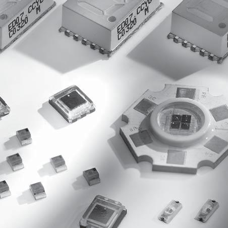
217
218 Optoelektronische Bauelemente SMT Optoelectronic Components SMT Inhaltsverzeichnis / Contents Seite / Page LEDs ACULED TM Photo-Pin Diodes Reflex Sensor Point Light LED Segment Display Packages Zertifiziertes QM-System: ISO/TS 16949:2002 ISO 9001:2000 Certified QM-System: ISO/TS 16949:2002 ISO 9001:
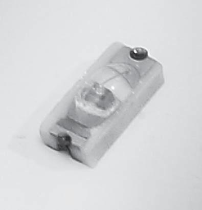
219 SMT-LEDs
220 LED - Visible SMD LED CR 10 Series (1205) CR 50 Series (1205) Type CR 10 SG Colour standard green Wave length in nm Luminous intensity in mcd (lf=20ma) min. typ. Forward voltage in V (lf=20ma) Continuous forward current in ma Orientation ,3 50 Cathode CR 10 YG yellow green ,3 50 Cathode CR 10 Y yellow ,1 50 Cathode CR 10 R orange red ,0 50 Cathode CR 10 NR red ,9 60 Cathode CR 10 1M CR 50 SG hyper red standard green ,8 70 Cathode ,2 50 Cathode CR 50 YG yellow green ,2 50 Cathode CR 50 Y yellow ,1 50 Cathode CR 50 R orange red ,0 50 Cathode CR 50 NR red ,9 60 Cathode CR 50 SR CR 50 UR CR 50 1M super red ultra red hyper red ,85 70 Anode ,8 70 Cathode ,8 70 Anode
221 Note for visible SMD LED : - Most types are also available with diffused epoxy, ordering code: CR12 / 52 xx - CR10 can be delivered in solid strips - All types can be glued - More colours on request General Data at 25 C: Power Dissipation 130 mv Reverse Voltage 5 V Peak Current 800 ma Cont. Current 75 ma Radiation Angle 180 Temperatures: Operating -25 to +80 C Storage -25 to +120 C Soldering 10 sec at 250 C Junction 120 C CR 60 Series (1205) Ceramic SMD LED - Low Profile Height 0,6 mm only Type Colour Wave length in nm Luminous intensity in mcd (l F =20mA) min. typ. Forward voltage in V (l F =20mA) typ. Continuous forward current in ma Orientation CR 60 B blue ,0 25,0 3,3 30 Cathode CR 60 G green ,0 180,0 3,3 30 Cathode CR 60 R red ,0 140,0 2,0 60 Cathode CR 60 Y yellow ,0 130,0 2,0 60 Cathode SR 10 Series (1206) High Precision of Chip Position Type Colour Wave length in nm Luminous intensity in mcd (l F =20mA) min. typ. Forward voltage in V (l F =20mA) Continuous forward current in ma Orientation SR10 HR hyper red ,8 30 Anode SR10 HR-B hyper red ,8 30 Anode SR10 UR ultra red ,8 30 Cathode SR10 UR-B ultra red ,8 30 Cathode
222 EM 20 Series (0805) Surface Mount LED 2,0 x 1,25 mm Type Colour Wave length in nm Luminous intensity in mcd (l F =20mA) Forward voltage in V (l F =20mA) Forward current I F [ma] min. typ. EM 20 SG standard green ,5 2,2 25 EM 20 Y yellow ,1 30 EM 20 UY ultra yellow ,2 25 EM 20 A amber ,2 30 EM 20 R red ,5 2,0 30 EM 20 SR super red ,85 30 EM 20 UR ultra red ,85 30 INFRARED SMD SERIES CR 10 Series (1205) CR 50 Series (1205) Type at 50 ma (MW) Power at 20 ma (MW) Rise time tr in ns Fall time tf in ns Forward voltage at 50 ma (V) at 20 ma (V) Wave length in nm Continuous forward current in ma Orientation CR 10 IRD 6,3 2, ,75 1, Anode CR 50 IRK 11,4 4, ,35 1, Cathode CR 50 IRDA 20,0 8, ,5 1, Cathode CR 50 IRH 10,6 4, , Anode See package and solder terminals

223 ACULED TM
224 ACULED TM Setting the Mood TM All Colour Ultrabright Superior brightness and excellent colour mixing in a compact size. ACULED is truly setting the mood with illumination. Test it out with our Evaluation Kit. Features and Benefits: - High-power light source utilizing multi chip-on-board (COB) technology - Superior brightness resulting from excellent quality LED chips and superior thermal management - Compact size - Excellent colour mixing achieved by a separate anode and cathode for each colour (red, green, blue) - Close individual chip placement to produce an exquisite white colour mix - One blue, one red and two green chips (green connected serially) - Lambertian emitter with 120 aperture - Up to 4.5 W electrical power Applications: - High power light source for general illumination - Vision systems - Architectural lighting - Mood lighting - Medical lighting - Backlighting - Displays and signs Maximum Ratings at 25 C Symbol Values Unit Operating temperature range T op -40 to 100 C Storage temperature T st -40 to 100 C Junction temperature T J 120 C Forward current per colour I P 350 ma Surge current per colour T op 700 ma Forward voltage Power consumption RED BLUE V R 5 V GREEN V R 10 V RED P tot 1,05 W GREEN P tot 3,2 W BLUE P tot 1,8 W
225 Parameter Symbol RED GREEN BLUE Unit Luminous flux typ. Ø V ,7 lm Luminous flux typ. Ø V λ dom (0) (0) (0) nm (1) (1) (1) nm Dominant wave length * (2) (2) nm (3) nm Special typ. Δ λ nm Forward typ. V F 2,5 7,0 3,6 V max. V F 3,0 8,0 4,0 V Optical efficiency typ. η opt lm/w Optical efficiency 50mA typ. η opt lm/w Optical efficiency typ. η opt lm/w Viewing angle at 50 % typ. 2 ψ degree Radiating surface typ. A rad 1,0 2x1,0 1,0 mm2 Thermal resistance typ. assembly:10 K/W * binning: (0) = standard, (1) = main binning Adequate heat sink is required. Derating must be observed to maintain junction temperature below maximum. ** Please note: These values are measured at realistic working conditions for thermal equilibrium with a small heat sink Attention: Some suppliers present only optimized laboratory conditions. *** Values for board-temperature of 25 C
226


227 ACULED TM LHS-AL25 Lens System The ACULED LHS-AL25 lens system is designed to collect and guide the light emitted by the ACULED RGB LED. Easily attachable lenses lead the beam into a smaller angle to provide more light power in a particular certain direction. With the LHS-AL25 the ultra bright ACULED RGB light source is even further setting the mood in illumination. Test it using our Evaluation Kit. Features and Benefits: - High luminous flux by collecting lenses - Small footprint due to complex lens design - Optics including micro lenses for excellent colour mixing - Two different aperture angles available, customized optics on request - Increased luminous intensity compared to bare ACULED Applications: - High power light source for general illumination - Vison systems - Architectural lighting - Mood lighting - Medical lighting - Backlighting - Displays and signs Material Transmission Holder Operating and Storage Temperature Divergence Angles ACULED LHS-AL25-L22 Optical grade PMMA Typically > 90 % from 500 nm to 700 nm ABS -40 C to +80 C typically 22 with 2.6 mm micro lenses (medium beam) ACULED LHS-AL25-L32 Optical grade PMMA Typically > 90 % from 500 nm to 700 nm ABS -40 C to +80 C typically 32 with 1.7 mm micro lenses (wide beam) Flammability class (1,5 mm nominal thickness): - Optics (PMMA): class HB second IEC Lens holder (PC-ABS): UL recogniram 694V-0 flc

228 Dimensions and tolerances of the ACULED. The middle of the gap cross defined by the four chips should be on the optical axis of the lens. More Details on request. Attention: Using lenses can concentrate the total amount of light emitted by a LED. Take care to avoid any direct exposure to human eyes in your application

229 ACULED TM Evaluation Kit An evaluation kit has been designed to run and test the ACULED in your application. It is easy to use and does not require specialized technical know how. Please contact us to receive a product description and additional information on how to obtain the Evaluation Kit. Note: According to IEC (EN ) LED Radiation: Do not view directly with optical instruments. Class 1M LED product for red and green chip. Do not look into the beam. Class 2 LED product for blue chip

230 Operating modes: Manual colour- and intensity-setting: Individual controls for setting RED, GREEN and BLUE allow unique compositions of colour and intensity. Any current setting may be stored permanently in an on-board electronic. Automatic mode: The controller-board can be switched to an Autoplay-Mode. A fixed sequence is used to drive the RGB-emitter with changing colour and intensity. Remote Control: A serial interface is part of the controller-board. It allows remote control via PC. By means of short commands, the colour and intensity of the ACULED will be adjusted. These commands are sent very easily by a Windows program (included in the Evaluation Kit), or may be initiated manually by any terminal program / e. g. HyperTerminal). Scope of supply: The Evaluation Kit will be delivered as a complete set. The kit consists of a power supply unit ( V), the ACULED mounted on a heat sink, including connector cable, interface cable for remote control via PC, the software control panel running on Windows 98, 2000 and XP, documentation and packaging

231 Photo-Pin Diodes
232 Photo-Pin Diodes CR 50 Series (1205) Dark Current I R (na) Active Area A (mm 2 ) Rise / Fall Time T r /t f (µs) Type Reverse voltage (V) Sensitivity (A/W) Capacitance (pf) CR 50 DE 50 0,5 0,31 0,5 3 2,5 PFD ,71 0,6 0,2 25 SR 10 Series - High precision of chip position Dark Current I R (na) Active Area A (mm 2 ) Rise / Fall Time T r /t f (ns) Type Reverse voltage (V) Sensitivity (A/W) Capacitance (pf) Tolerance Chip Position SR 10BP , ±100µm SR 10 BP-B , ±50µm SR 10 DE 50 0,5 0,56 0, ±100µm SR 10 DE-B 50 0,5 0,56 0, ±50µm SR 10 SPD 470-0,9 10 0,03 0,7 0,18 N/A N/A ±100µm SR 10 SPD 525-0,9 5 0,005 0,73 0,25 N/A N/A ±100µm SR 10 SPD 880-0,9 5 0,001 0,73 0,25 N/A N/A ±100µm Photo Transistors N/A = Not Available/Applicable Type Active area A in mm 2 Rise / Fall Time T r /t f (ns) Dark current I CEO in na Spectral range (nm) Peak Sensitivity Wavelength (nm) Vce (V) P-current I pce (ma) CR 10 TE 0,19 10/ CR 50 TE 0,19 10/ All detectors available with daylight filter on special request. More information see package and solder terminals

233 Reflex Sensor
234 SMD - Reflex Sensor CRS 20 Reflex Sensor Unit with NIR-LED and Photo-Transistor - Surface mounting device - Complete ceramic housing - High temperature range - Miniature size - Best reflective distance: 0,9 mm (paper) - Solder pads conform with MIL-Std. 883 B This opto device is specially designed for all applications where the space is very limited and highly reliable product is needed. Especially for hybrid and SMT. The solder pads are a very good heat sink, so that high power dissipation is achievable. Type Rise Fall Time T r /t f (ns) Collector emitter breakdown V ceo (V) (I=100µA) Emitter collector breakdown V ceo (V) (I=100µA) Dark Current I ceo (na) (V=20V) Wavelength (nm) Forward voltage (V) (I F =20mA) Cont forward current (ma) CRS , ,2... 1,

235 Point Light LED
236 Point Light LED - Homogenous light point - wide viewing angle - Lighting emitting area only 0,006 mm diameter TYPE PL 06-R red Optical and electrical Characteristics I F = 20 ma, ambient temperature = 25 C Luminous flux 2 mlm Peak emission wavelength 660 nm Dominant emission wavelength 643 nm Spectral half band width 20 nm Forward voltage 2,5 V max Emmision hole ø 60 µm Light emission angle 100 Maximum Ratings at 25 C Power dissipation P tot 200mW Derating linear 2,8 mw/ C Peak forward current I FSM (10µs) 500 ma Continuous forward current I F 100 ma Junction temperature T j 120 C Storage temperature T st -25 to 120 C Operating temperature T op -25 to 80 C Soldering temperature T sold (10sec) 245 C source To l. : ± 0, 1 5 Light emitting area PL06 diameter ø 0,06 mm holes for solder joints PL 22 ø 0,22 mm
237 Driving & Test Packaging Chips Checklist for Customized Solution CERLED Company Telephone Name Telefax Address ZIP / City Website Branch Product Name Application QTY / Year Pcs. Euro / $ Date required: Specification (E = Emitter; D = Detector) Parameter E/D Conditions Customer Request STELCO Confirmation Wavelength E nm Die size E M Brightness F = ma mcd/ mw Forward current (AC/DC) E ma Rise time E ns Spectral range D nm Active area D nm Sensitivity = nm A/W Dark current R = V na Rise time = nm ns V R = V R L = Ω Reverse voltage D V Capacitance R = V pf Special features D If standard chip type Features Chip Placement # of Chips X-Pitch Y-Pitch Tolerance Substrate size Length Width Height Reference Substrate Ceramic PCB Flex Others Encapsulation Epoxy Epoxy Premolded Window Mold Frame Caps Filter Terminals SMD PIN Flex Others Filter Special features Features Temperature Range Operating C Storage C Expected processing Reflow Soldering Glueing By hand Driving requirements Parameter for testing STELCO STELCO
238

239 7 Segment Display
240 7 Segment Display - Brilliant light output - Only 4 mm total height - Withstands high solder treatment - For all miniature applications - On 24 mm blister tape Peak Dominant Max Max Min luminous Typ luminous Type emission wavelength (nm) emission wavelength (nm) forward voltage (V) reverse current (µa) intensity per segment (mcd) intensity per segment (mcd) Forward voltage (V) (I F =20mA) ED-07.CC-R , ,5 2 ED-07-CA-R , ,5 2 ED-07.CA-YG ,4 10 1,4 2,3 2 ED-07.CC-YG ,4 10 1,4 2,
241 Packages NEW: All Color Ultrabright LED Package ACULED TM red, green, blue, multi chip on board high power with excellent color mixing compact size SMT-LEDs Package A1, A2, A3, A4( ) UV-visible-infrared high brightness, high speed InGaN, GaAs, GaP, GaAsP, GaAlAs, AlInGaP (M2, E UR OLE D) Point Light LEDs visible - infrared 50μm - 220μm diameter AlInGaP, GaAlAs, GaAsP Package P SMT-7-Segment Displays visible (red and green) only 4mm total height special colors available Package K Photo PIN-Diodes visible - infrared small size silicon Package A2, A3, D Photo Transistors visible - infrared small size, photo darlington silicon Package A2 Reflex Sensors infrared ceramic package, small size GaAs - infrared / silicon photo transistor Package H

242 max 3.00 max max 3.20 max max 3.20 max Package ACULED TM Package A1 Package A ± ± Package A3 Package A4 Package D Package H Package K Package P ceramic MCPCB PCB
243

244 Keramik-Montage-Teile Ceramic Mounting Parts Zertifiziertes QM-System: ISO/TS 16949:2002 ISO 9001:2000 Certified QM-System: ISO/TS 16949:2002 ISO 9001:
245
246 Keramik-Montage-Teile Ceramic Mounting Parts Inhaltsverzeichnis / Contents Seite / Page Allgemein General Keramik-Montage-Teile nach Kundenspezifikation 238 Ceramic Mounting Parts acc. to customers specification Anwendungsbeispiele 239 Application examples Zertifiziertes QM-System: ISO/TS 16949:2002 ISO 9001:2000 Certified QM-System: ISO/TS 16949:2002 ISO 9001:
247 Metallisierte und/oder armierte Keramik-Montage-Teile Keramik, ein traditioneller Werkstoff, ist seit Jahrzehnten aus vielen Zweigen der Technik nicht mehr wegzudenken. Bewährte und moderne Keramik-Werkstoffe zeichnen sich durch eine Reihe außergewöhnlicher Eigenschaften aus: Mechanisch: Verschleißfestigkeit Härte Formstabilität Niedrige Dichte Elektrisch: Isolierfähigkeit Durchschlagsfestigkeit Hohe Dielektrizitätskonstanten Thermisch: Temperaturfestigkeit Hohe Temperatur-Wechselbeständigkeit Geringe Wärmeausdehnung Chemisch: Korrosionsbeständigkeit Metallized and/or Armoured Ceramic Mounting Parts Hightech ceramics have established themselves as essential materials for many technical applications in the past decades. Traditional and modern ceramic materials provide users with a combination of unique properties: Mechanical: Wear resistance Hardness Geometric stability Low density Electrical: Insulation property Dielectric strength High dielectric constant Thermical: Temperature resistance High resistance changes in temperature Low heat dilatation Chemical: Corrosion resistance
248 Die wichtigsten Keramik- Eigenschaften Technische Eigenschaften: Major Lines of Ceramic Materials Technical Data: C-221 C-310 bis/ to C-350 C-795 C-799 Mechanisch Mechanical: Symbol Symbol Einheit Unit Sonder-Steatit kleiner Verlustfaktor Special Steatite low dissipation factor Dielektrische Materialien Dielectric Materials Aluminiumoxid Alumina % Al 2 O 3 Aluminiumoxid Alumina > 99 % Al 2 O 3 Offene Porosität Open porosity [Vol %] Dichte min. Density min. r [10-3 kg m -3 ] 2,7 31-4,5 3,5 3,7 Biegefestigkeit Flexural strength sb [Mpa] Elastizitätsmodul Modulus of elasticity E [Gpa] Elektrisch: Electrical: Durchschlagsfestigkeit Dielectric strength E d [kvmm -1 ] Stehspannung min. Withstand voltage min. U [kv] Permittivitätszahl Permittivity Hz ε r [--] Verlustfaktor bei Dissipation factor at 20 C, Hz tan d pf [10-3 ] 1, ,5 0,2 Verlustfaktor bei Dissipation factor at 20 C, 1 MHz tan d 1M [10-3 ] 1,2 0, Spez. Widerstand bei Spec. Resistance at 20 C pv >20 [Wm] Spez. Widerstand bei Spec. Resistance at 600 C pv >600 [Wm] Thermisch: Termical: Mittlerer Längenausdehnungskoeff. bei Average Coeff. of linear expansion at C a [10-6 K -1 ] Spez. Wärmekapazität bei Spec. Heat capacitance at C C p, [Jkg -1 K -1 ] Wärmeleitfähigkeit Therm. Conductivity I [Wm -1 K -1 ]
249 Keramik-Montageelemente nach Kundenspezifikation Ceramic Mounting Parts Custom-designed SUMIDA fertigt Keramik-Montageelemente nach Ihren Wünschen und Ihren Spezifikationen. Gerne erarbeiten wir mit Ihnen gemeinsam Lösungen, bei welchen - neben Funktionalität, Qualität und Verfügbarkeit - die kostenoptimierte Fertigung der Problemlösung im Vordergrund steht. Neben keramischem Material-Know How kann SUMIDA folgende Bearbeitungsmöglichkeiten für Keramiken anbieten: - Schleifen, Polieren, Glasieren... - Metallisieren mit nachfolgend galvanischer Verstärkung, z. B. mit Ag, Ni, Cu, Sn, Sn/Pb, Pd, Au... - Löten, Kitten, Kleben, Stecken, Pressen, Crimpen, Bördeln, Nieten, Rollieren, Schrauben, Klemmen... Applikationen: Aufgrund der besonderen Eigenschaften bietet die Keramik eine Vielfalt von Anwendungen. Nachfolgend einige Beispiele: - Elektrotechnik, Isolier- und Lichttechnik - Elektronik - Meßgeräteindustrie - Sensorik - Medizintechnik - Präzisionstechnik - Maschinen- und Vorrichtungsbau - Chemie- und Verfahrenstechnik SUMIDA produces ceramic mounting elements according to customers specification. We would be pleased to develop - together with ours clients - technical solutions combining quality and manufacturability resulting in optimized and low cost production. Besides the ceramic material know how SUMIDA offers the following possibilities of a further treatment of the ceramics: - Grinding, polishing, glazing... - Metallizing with subsequent galvanic strengthening for example with Ag, Ni, Cu, Sn, Sn/Pb, Pd, Au... - Soldering, cementing, glueing, inserting, pressing, crimping, flanging, rivetting, rolling, screwing, clamping... Applications: The ceramic offers a variety of applications due to its special properties. Examples: - Electro-technique, insulating and light technique - Electronics - Measuring equipment industry - Sensor technique - Medical technique - Precision technology - Engineering technologies - Chemical engineering and processing technology

250 Beispiele kundenspezifischer Keramik-Produkte Examples for custom-designed ceramic products Halterungen Stützer Achsen Lötstützpunkte Lötleisten Regler-Justierschrauben Keramik-Durchführungen - einlötbar - einschraubbar Keramik-Rohre Kapazitiv-Sensorplatte Träger für Induktiv-Sensor Sensor-Aufnehmer Mountings Supports Axles Soldering Terminals Soldering Strips Control Adjusting Screws Ceramic Bushings - solderable - screwable Ceramic Tubes Capacitive Sensor Plate Support for Inductive Sensor Sensor Receiver Nehmen Sie Kontakt mit uns auf - wir finden Ihre kundenspezifischen Lösungen! Nutzen Sie 75 Jahre Erfahrung in keramischen Bauelementen! Get into touch with us - we will find your custom-designed solutions! Take advantage from a 75 years experience in ceramic components!
251

252 Piezokeramische Bauelemente Piezoceramic Components Zertifiziertes QM-System: ISO/TS 16949:2002 ISO 9001:2000 Certified QM-System: ISO/TS 16949:2002 ISO 9001:
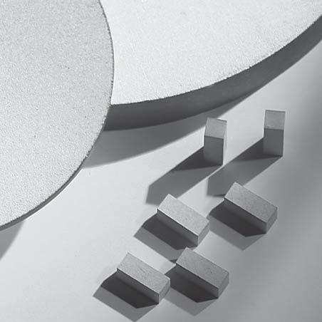
253
254 Piezokeramische Bauelemente Piezoceramic Components Inhaltsverzeichnis / Contents Seite / Page Piezokeramik - Grundlagen Piezoceramic - Basics SUMIDA Piezokeramik SUMIDA Piezoceramics Zertifiziertes QM-System: ISO/TS 16949:2002 ISO 9001:2000 Certified QM-System: ISO/TS 16949:2002 ISO 9001:
255 Piezoelektrizität Der piezoelektrische Effekt wurde bereits 1880 von den Gebrüdern Curie an natürlichen Kristallen entdeckt. Zu den damals bekannten piezoelektrischen Stoffen zählten Seignette-Salz und Turmalin. Die in den 30er Jahren des 20sten Jahrhunderts für die Herstellung von elektrischen Kondensatoren entwickelten ferroelektrischen Keramiken zeigen ebenfalls piezoelektrische Eigenschaften. Gezielte Forschung und Materialentwicklung führte zu den heutigen piezokeramischen Werkstoffen mit hohem Wirkungsgrad und Variationsmöglichkeiten der Materialparameter in weiten Bereichen. Direkter Piezoeffekt Wirkt auf einen piezoelektrischen Körper eine Kraft, so entstehen durch die dielektrische Verschiebung Oberflächenladungen, und ein elektrisches Feld baut sich auf. An aufgebrachten Elektroden kann dieses Feld als elektrische Spannung abgegriffen werden. Werden die Elektroden kurzgeschlossen, gleichen sich die Oberflächenladungen in Form eines Stromes aus. Piezoelectricity The piezoelectric effect of natural crystals was discovered by the Curie brothers in At that time Rochelle salt and tourmaline were the best known piezoelectric materials. The ferroelectric ceramics, developed in the 1930s for the production of electrical capacitors, also show piezoelectric properties. Concentrated research and material development led to the present highly-effective piezoceramic materials whose material parameters can be varied in a wide range and can therefore be optimally adapted to the customers requirements. Direct Piezoelectric Effect If a force is applied to a piezoelectric body, surface charges are induced by the dielectric displacement and therefore an electric field is built up. On applied electrodes this field can be tapped as electrical voltage. If the electrodes are shorted, the surface charges balance out by a current. F / F F / F U U I I Indirekter Piezoeffekt Wirkt auf einen piezoelektrischen Körper ein elektrisches Feld, so verformt er sich. Wird der Körper daran gehindert sich zu verformen, entsteht eine elastische Spannung T. Auf die Vorrichtung, die den piezoelektrischen Körper an seiner Verformung hindert, wird damit eine Kraft F ausgeübt. Indirect Piezoelectric Effect If an electric field acts on a piezoelectric body it becomes distorted. If this distortion is prevented, an elastic stress T occurs. A force F is thereby applied to the device which prevents the distortion of the piezoelectric body. U
256 Diese Umkehrung des direkten Piezoeffektes wird als indirekter oder auch reziproker Piezoeffekt bezeichnet. In der Praxis wird der indirekte Piezoeffekt sowohl im statischen als auch im dynamischen Betrieb genutzt. / This reversal of the direct piezoelectric effect is defined as indirect or inverse piezo effect. In practice, the indirect piezo effect is used in static as well as dynamic operation. dynamisch / dynamic - + 0V Bei gleichem Arbeitsvermögen kann durch den Verbund von Metall und Keramik die Auslenkung vergrößert werden bei gleichzeitiger Reduzierung der Kräfte. In case of equal working conditions the deviation can be increased by the compound of metal and ceramic with simultaneous reduction of force. Resonanzeffekte Resonance Effects Jeder Körper hat eine mechanische Grundresonanz, die durch seine Geometrie festgelegt ist. Daneben treten harmonische Oberschwingungen und Resonanzen in anderen Moden auf. Dieser Effekt wird zur gezielten Bestimmung der Materialparameter genutzt. Radialresonanz einer Scheibe Bedingung: Durchmesser >> Dicke Each body has a mechanical basic resonance, determined by its geometry. Moreover, harmonics and resonances in other modes are arising. This effect is used for specific determination of the material parameters. Radial resonance of a disc condition : diameter >> thickness Längs- und Querresonanz eines Stabes Bedingung : Länge >> Breite und Dicke Longitudinal and transversal resonance of a bar condition : length >> width and thickness
257 Piezokeramische Werkstoffe Der Übergang von den "natürlichen" piezoelektrischen Werkstoffen wie Turmalin und Quarz zu den synthetischen ferroelektrischen Keramiken entwickelte sich in den Jahren nach Aus den hochwertigen Kondensatorkeramiken auf der Basis Bariumtitanat wurden gezielt piezokeramische Werkstoffe entwickelt, deren Eigenschaften sich über einen weiten Bereich durch Variationen der Materialzusammensetzung beeinflussen lassen. Blei-Zirkonat-Titanat Die heutigen piezokeramischen Materialien sind meist oxidische Werkstoffe auf der Basis von Bleioxid, Zirkonoxid und Titanoxid. Zur Feinabstimmung der Materialparameter bzw. deren Stabilisierung werden unter anderem Oxide der Metalle Lithium, Magnesium, Zink, Nickel, Mangan, Niob, Antimon oder Strontium zugegeben. Durch unterschiedliche Mischungsverhältnisse der Grundstoffe, Mahldauer, Kalzination, Formgebung und Sinterung lassen sich die physikalischen Eigenschaften der resultierenden Blei-Zirkonat-Titanat-Verbindungen steuern. Kristallstruktur und Polarisation Den Grundaufbau von Blei-Zirkonat-Titanat zeigt die folgende Abbildung. Piezoceramic Materials The change from the "natural" piezoelectric materials such as tourmaline and quartz to the synthetic, artificial ferroelectric ceramics occurred in the years following Piezoceramic materials - whose properties could be influenced over a wide range by variations of the material composition - were developed from the high-quality barium-titanate based ceramics used for capacitors. Lead-zirconate-titanate Nowadays piezoceramic materials are mostly oxide materials based on lead oxide, zirconium oxide and titanium oxide. Other metal oxides like lithium, magnesium, zinc, nickel, manganese, niobium, antimony or strontium are added for the appropriate adjustment or stabilization of the material parameters. The physical properties of the resulting lead-zirconate-titanate compound can be controlled by different composition ratios of the basic materials, by grinding duration, calcination, shaping and sintering. Crystal structure and polarization The figure below shows the basic structure of leadzirconate-titanate. Die Kristallstruktur leitet sich vom Mineral Perowskit (CaTiO 3 ) her. Oberhalb einer bestimmten Temperatur, der Curie-Temperatur, hat das Gitter kubische Struktur, d.h. es besteht aus regelmäßig angeordneten Sauerstoffoktaedern, in deren Zentrum die Titan- bzw. Zirkonionen sitzen. Beim Unterschreiten der Curie-Temperatur ordnet sich das Gitter zu einem Gemisch rhomboedrischer und tetragonaler Kristalle um. In diesen ist das zentrale Titan bzw. Zirconium nicht mehr im Zentrum, so dass es zu einer Ladungstrennung kommt und damit zur Ausbildung elektrischer Dipole. The crystalline structure is derived from the mineral perovskite (CaTiO3). Above a specific temperature, called Curie temperature, the lattice has a cubic structure, that means it consists of regularly arranged oxygen octahedra in the center of which the titanium resp. zirconium is placed. Below the Curie temperature the lattice structure reorders to a mixture of rhombohedral and tetragonal cystals in which the central titanium resp. zirconium is no longer placed in the center and so a separation of charges takes place and electrical dipoles are formed
258 Die Richtungen der einzelnen Dipole sind zunächst ungeordnet in den Kristalliten verteilt, so dass die resultierende, nach außen hin messbare Polarisation des Materials Null beträgt. Erst durch einen Polarisationsprozess wird eine Piezokeramik piezoelektrisch. Das bei diesem Prozess angelegte hohe elektrische Feld bewirkt in jedem Kristall eine Ausrichtung der einzelnen Dipole annähernd in Richtung des angelegten Feldes. First the directions of the single dipoles are distributed randomly in the crystallites so that no resulting polarization can be measured. It is only after a polarization process that the piezoceramic becomes piezoelectric. The strong electric field applied during the process causes an alignment of the individual dipoles in each crystallite along the direction of the applied field. Z + - Nach dem Entfernen des Feldes bleibt die eingeprägte Ausrichtung erhalten. Die Keramik ist remanent polarisiert. After the field has been removed the distinct alignment is maintained. The ceramic has remanent polarization
259 Piezoelektrische Grundgleichungen und Definitionen Koordinatensystem und Indizierung Die in den Datenblättern aufgeführten Materialkonstanten sind an definierten Körpern (entsprechend den IEEE-Standards) ermittelte Richtwerte. Zur Kennzeichnung wird gemäß internationalen Vereinbarungen von einem kartesischen Koordinatensystem ausgegangen. Es ist mit den Ziffern 1, 2 und 3 bzw. den Buchstaben X, Y und Z indiziert. Bei Piezokeramiken wird die Z-Richtung definitionsgemäß als Polarisationsrichtung festgelegt. Die Indizierung 4, 5 und 6 beschreibt mechanische Spannungen, die tangential zu den das Koordinatensystem aufspannenden Flächen wirken. Sie können, wie im Bild dargestellt, als Drehungen um die jeweiligen Achsen verstanden werden. Piezoelectric Basic Equations and Definitions Coordinate System and Indication The material constants listed in the data sheets are standard values determined on defined bodies (corresponding to the IEEE Standards). In accordance with international agreements, the Cartesian coordinate system is used as the basic for indication. It is indicated with numbers 1, 2 and 3 or the letters X, Y and Z. At piezoceramics the Z direction is determined as the polarization direction. The numbers 4, 5 and 6 describe the mechanical stresses which act tangentially to the areas defining the coordinate system. As represented in the figure, they can be understood as rotations around each axis. 3 Z Y 4 1 X
260 Ein tiefgestellter Doppelindex bei den Materialkonstanten kennzeichnet die Verknüpfung von elektrischen und mechanischen Größen: Die erste Zahl gibt die Richtung der Erregung vor, die zweite Zahl beschreibt die Richtung der Systemreaktion. So bezeichnet z.b. k 31 den Koppelfaktor für einen Körper, der in Polarisationsrichtung durch ein Wechselfeld erregt wird, aber senkrecht dazu schwingt. A double index at the material constants characterizes the connection between electrical and mechanical parameters: the first figure specifies the direction of the stimulation, the second figure describes the direction of the system reaction. k 31, for example, designates the coupling factor for a body which is stimulated by an alternating field in the direction of polarization, but which oscillates perpendicularly to it. Z k 31 Um mechanische und elektrische Grenzbedingungen darzustellen, erfolgt eine zusätzliche Kennzeichnung durch hochgestellte Buchstaben. Im Einzelnen bedeuten: Further indication with exponents represents mechanical and electrical boundary conditions. In detail : E D S T elektrisches Feld, konstant dielektrische Verschiebung, konstant relative Dehnung, konstant mechanischer Druck, konstant E D S T electrical field, constant dielectric displacement, constant relative strain, constant mechanical stress, constant
261 Piezoelektrische Gleichungen Piezoelectric Equations Die gesamte Thermodynamik piezoelektrischer Werkstoffe hier zu beschreiben, würde den Rahmen bei weitem sprengen. Die Phänomenologie ist unter anderem in /6/ beschrieben. Hier sollen nur kurz die Grundlagen angedeutet werden. Ausgehend von thermodynamischen Grundgleichungen kann ein Set von Gleichungen abgeleitet werden, das den Zustand eines piezoelektrischen Körpers eindeutig beschreibt. Für alle dielektrische Materialien gilt: r r r D= E + P ε 0 It would be far behond the scope of this catalogue to give a complete description of the thermodynamic of piezoelectric materials. The phenomenology is described for example in reference /6/. Here only a basic outline can be given. Starting with basic equations of thermodynamics a set of equations can be derivated to completely describe the state of a piezoelectric body. All dielectric materials follow: Die gesamte in dem piezoelektrischen Körper gespeicherte Energie kann als innere Energie U beschrieben werden. Die Änderung der inneren Energie kann nach Gibbs bestimmt werden mit: The total energy stored in the piezoelectric body can be described as the internal energy U. The change of this internal energy can be determined acc. to Gibbs: du = Θ dσ + EidDi + TλdSλ U Θ δ E D T S Innere Energie Temperatur Entropiedichte elektrisches Feld elektrische Flußdichte mechanische Spannung Deformation U Θ δ E D T S internal energy temperature entropy density electrical field electrical flux density mechanical stress deformation Der Term Θ dσ beschreibt die in dem System enthaltene thermische Energie, E i dd die elektrische Feldenergie und T λ ds λ die mechanische Deformationsenergie. The term Θ dσ describes the thermal energy stored in the system, E i dd the electrical field energy, and T λ ds λ the mechanical deformation energy. Feldstärke E k Flußdichte d k D i p k -e k - k piezoelektrische Eigenschaften e i ik i pyroelektrische Eigenschaften d i p i Spannung T S Entropie De- formation S - thermoplastische Eigenschaften C Temperatur
262 Skalare Größen wie die Temperatur sind richtungsunabhängig, andere wie die Feldstärke sind richtungsabhängig. Daher sind auch die Beziehungen richtungsabhängig und werden als Tensoren verschiedener Grade oder Matrizen dargestellt. Aus diesen Grundgleichungen können die jeweils interessierenden Beziehungen hergeleitet werden. Anschaulich werden die Materialkonstanten und ihr Zusammenhang zwischen unabhängigen Zustandsgrößen Temperatur, Feldstärke und mechanischer Spannung und den abhängigen Größen Flußdichte, Deformation und Entropie in dem Diagramm nach Heckman dargestellt. Praktische Bedeutung hat insbesondere der Koppelfaktor, der den direkten Vergleich verschiedener Materialien erlaubt. Er beschreibt die Fähigkeit eines Materials, elektrische Energie in mechanische Energie umzuwandeln und umgekehrt. Der Zusammenhang zu den bereits definierten Größen der Grundgleichungen lautet allgemein: Scalar units like temperature are independent of direction, others like field strength are depending on direction. Therefore, all the relations as well are depending on direction and are therefore represented by tensors of different grade or matrix notation. All interesting relations can be deduced from these basic equations. The material constants and their relation between the independent variable temperature, field strength and mechanical stress and the dependent units flux density, deformation and entropy can be visualized in a diagram acc. to Heckman. In practice especially the coupling factor is very important, which allows a direct comparison of different materials. It describes the ability of a material to transform electrical energy into mechanical energy and vice versa. The connection with the parameters of the basic equations already described is as follows: Bestimmung der piezokeramischen Materialparameter Grundsätzlich muss unterschieden werden zwischen Messungen bei geringen Feldstärken (<1V/mm) im Kleinsignalbetrieb und Messungen bei hohen Feldstärken (>100V/mm) im Großsignalbetrieb. Kleinsignalmessungen Der Piezo wird elektronisch durch einen Serien- und Parallelschwingkreis, wie im nachstehenden elektrischen Ersatzschaltbild gezeigt, simuliert. Measurement of the Piezoceramic Material Parameters Basically one has to distinguish between measure-ments at low field intensities (<1V/mm) at small-signal applications and measurements at high field intensities (>100V/mm) at large-signal applications. Small-signal measurements The piezo element is electronically simulated by a series and parallel resonant circuit, as shown in the following equivalent circuit diagram. C0 L C1 R Solch ein Schwingkreis kann durch zwei Frequenzen charakterisiert werden: Bei Serienresonanz ist der Zweig L - C1 in Resonanz, der untere Zweig des Ersatzschaltbildes wird niederohmig, und die Impedanz zeigt ein Minimum. Bei der Parallelresonanz ist der Kreis L - (C0 + C1) in Resonanz, der Schwingkreis wird hochohmig, und die Impedanz hat ein Maximum. Such a resonant circuit can be characterized by two frequencies: At the series resonance, branch L - C1 is in resonance, the lower branch of the v4(low522 m345.3atedthe fol [T*-h L6 Tive TDowerihmig, sent c
263 Impedanz bei der planaren Resonanz (gemessen an einer Scheibe Ø 5 x 0,5 mm) Impedance at the planar resonance (measured at a disc Ø 5 x 0,5 mm) PPK 21, 5 mm x 0,5 mm f p k eff = f 2 p f f 2 p 2 s Impedanz/Impedance[ ] f s Frequenz/Frequency [khz] Zur Berechnung der Materialparameter wird nachstehend aufgezeigte Zuordnung der mechanischen zu den elektrischen Größen angenommen. Mit dieser Zuordnung können durch das elektronische Vermessen der Resonanzfrequenzen die piezoelektrischen Größen bestimmt werden. The following correlation of physical and electrical parameters is taken for the evaluation of the material parameters. By this correlation the piezoelectric values can be determined by electronical measuring of the resonance frequencies. Physikalische Größe / Physical parameter Masse / Mass Elastizität / Elasticity Mechanische Verluste / Mechanical losses Freie Kapazität / Free capacitance Elektrische Größe / Electrical parameter Induktivität / Inductance Serienkondensator / Series capacitor Widerstand / Resistor Parallelkondensator / Parallel capacitor Durch eine geeignete Probengeometrie wird dabei sichergestellt, daß die Resonanz durch Schwingung nur in einer bestimmten Richtung erfolgt. Mit einem geeigneten Satz Probekörper kann so ein vollständiger Satz von Materialkonstanten bestimmt werden. Für die Messung wird meistens nur die Grundresonanz des jeweils interessierenden Modus herangezogen. A suitable sample geometry ensures that the resonance is caused by vibration in one certain direction only. A complete set of material constants can be determined by a suitable set of sample bodies. Normally the basic resonance is taken for the measurement of the mode of interest
264 Es ist zu beachten, dass bei jedem Probekörper alle möglichen Schwingungsmoden sowie die harmonischen Oberschwingungen auftreten und sich zum Teil überlagern. Am Beispiel einer runden Scheibe ist der Frequenzgang der Impedanz in nachstehender Abbildung gezeigt. Je nach Anwendung wird die planare Resonanz bei 200 khz oder die Dickenresonanz bei 2 MHz genutzt. Die Ansteuerelektronik muss auf dieses Verhalten Rücksicht nehmen. It must be taken into consideration that all possible vibration modes as well as harmonics occur at each sample and that they partially will superpose. The frequency response of the impedance is demonstrated in the following diagram in the example of around disc. Acc. to the application the planar resonance at 200 khz or the thickness resonance at 2 MHz is used. These characteristics must be taken into consideration by the selection electronic. PPK 21, 5 mm x 0,5 mm Impedanz/ Impedance [ ] Frequenz/Frequency [khz] Großsignalmessungen Im Großsignalbetrieb werden direkt Auslenkung und Kraft gemessen, die bei der Ansteuerung mit einer entsprechenden Feldstärke entstehen. Da die Wege sehr klein (einige Nanometer bis wenige Mikrometer) und die Kräfte sehr groß (einige Kilonewton) sind, bei Ansteuerspannungen bis einige Kilovolt, sind diese Messungen recht aufwendig. Interessant ist dabei die Abhängigkeit der Materialparameter von der Feldstärke. Durch den zunehmenden Anteil der induzierten Polarisation kommt es zu einer deutlichen Verstärkung der piezoelektrischen Kennwerte. Large-signal measurements In large-signal operation the direct deflection and the force arising at the selection with a corresponding field intensity are measured. These measurements take a lot of efforts as the paths are very short (some nanometers up to a few micro-meters) and the force is very high (some kilonewton) - in case of selection voltages up to some kilovolt. In this case the dependance of the material parameters versus field intensity is very interesting. A considerable strengthening of the piezoelectric values is observed due to the increasing share of the induced polarization
265 Symbolliste List of Symbols Symbol Symbol a Einheit Unit µm, mm Beschreibung Description Auslenkung, Hub excursion, displacement, stroke A m 2 Fläche Surface B, b mm Breite width C F Kapazität, elektrisch capacitance, electrical d, d mn (m,n = ) C/N = m/v piezoelektrische Ladungskonstante piezoelectric charge constant D C/m 2 dielektrische Verschiebung dielectric displacement D m (m = ) C/m 2 Komponente der dielektrischen Verschiebung component of the dielectric displacement E E m (m = ) f f S f P F V/m V/m 1/s Hz 1/sHz 1/s Hz N elektrische Feldstärke electrical strength Komponente der elektrischen Feldstärke components of the electric field strength Frequenz frequency Serienresonanzfrequenz series resonance frequency Parallelresonanzfrequenz parallel resonance frequency mechanische Kraft, Blockierkraft mechanical strength, blocking force g, g mn (m, n = ) Vm/N, m 2 /C piezoelektrische Spannungskonstante piezoelectric voltage constant h l mm A Höhe height elektrischer Strom electrical current
266 Symbolliste List of Symbols Symbol Symbol Einheit Unit Beschreibung Description k mn (m,n = ) 1 k p 1 piezoelektrischer Koppelfaktor piezoelectrical coupling factor planarer piezoelektrischer Kopplungsfaktor planar piezoelectric coupling factor l L N m (n = ) N p mm H m/s m/s Länge length Induktivität inductance Frequenzkonstante frequency constant planare Frequenzkonstante planar frequency constant P C/m 2 Polarisation polarization Q C elektrische Ladung electrical charge Q m 1 mechanische Schwinggüte mechanical Q-factor R R i S E, mn SD (m, n = ) mn m2 Ω Ω /N, 1/Pa elektrischer Widerstand electrical resistance Innenwiderstand (Quelle, Meßgeräte) internal resistance (source, measuring device) Elastizitätkonstante elasticity constant S, S m (m = ) 1 tan δ 1 Relative Längenänderung relative change of length, strain dielektrischer Verlustfaktor dielectric dissipation factor t t s T mm s N/m 2, Pa Dicke eines einzelnen Piezoelementes thickness of a single piezo element Schaltzeit switching time mechanische Spannung, Druck mechanical tension, stress
267 Symbolliste List of Symbols Symbol Symbol Einheit Unit Beschreibung Description T, T m (m = ) N/m 2, Pa Tk X 1/K, 10-6 /K Komponente der mechanischen Spannung components of stress Temperaturkoeffizient der Größe X temperature coefficient of the value X U U B V, kv V elektrische Spannung voltage Betriebsspannung operating voltage U m (m = ) V v m (m = ) m/s X 1 Y 1 Y N/m 2 Z 1 Z Ω ϑ C ϑ c C Komponente der elektrischen Spannung component of the voltage Schallgeschwindigkeit in Richtung einer Koordinate sound velocity in direction of a coordinate Koordinate eines kartesischen Systems coordinate of a Cartesian system Koordinate eines kartesischen Systems coordinate of a Cartesian system Youngscher Modul Young s modul Koordinate eines kartesischen Systems (Polarisatonsrichtung der Piezokeramik) coordinate of a Cartesian system (polarisation direction of piezoceramics) elektrischer Scheinwiderstand electric impedance Temperatur temperature Curietemperatur Curie temperature ε 0 F/m Dielektrische Feldkonstante dielectric field constant ε T / (m.n = ) 1 Relative Dielektrizitätskonstante mn relative permittivity Dichte ρ kg/m 3 density ϕ el Ωm Spezifischer elektrischer Widerstand resistivity
268 Literaturverzeichnis References /1/ Verschiedene Verfasser IRE Standards of Piezoelectric Crystals; Various authors Determination of the Elastic, Piezoelectric and Dielectric Constants - The Electromechanical Coupling Factor /2/ Verschiedene Verfasser IRE Standards on Piezoelectric Crystals: Various authors Measurement of Piezoelectric Ceramics /3/ Verschiedene Verfasser International Electrotechnical Commission Various authors IEC-Publication 483 /4/ Holland, R.; EerNisse, E.P. Design of Resonant Piezoelectric Devices Massachusetts Institute of Technology, Cambridge/Mass. Weiterführende Literatur / Recommended Textbooks /5/ Jaffe, B; Cook, W.R.; Piezoelectric Ceramics Jaffe, H.; Academic Press, London /6/ Tichý J.; Gautschi G. Piezoelektrische Meßtechnik Physikalische Grundlagen, Kraft-, Druck- u. Beschleunigungsaufnehmer - Verstärker Springer-Verlag /7/ Jendritza Dr.-Ing. D.J. Technischer Einsatz neuer Aktoren Techn. Akademie Esslingen - Kontakt u. Studium 484, expert-verlag /8/ Moulson A.J.; Herbert J.M. Electroceramics Chapman & Hall /9/ Ruschmeyer K. Piezokeramik - Techn. Akademie Esslingen - Kontakt und Studium 400, expert-verlag Es wird keine Gewähr übernommen, daß die angegebenen Produkte, Verfahren und Schaltungen frei von Schutzrechten Dritter sind. Mit den Angaben werden Produkte spezifiziert, nicht Eigenschaften zugesichert. Liefermöglichkeiten und technische Änderungen vorbehalten. Ein Nachdruck - auch auszugsweise - ist nur zulässig mit Zustimmung des Herausgebers und genauer Quellenangabe. There is no guarantee that the products, processes and circuits described are free from patent rights of third parties. The information given in this data sheet describe the products and shall not be considered as assured characteristics. We reserve the rights for delivery availability and technical changes. No part of this publication may be reproduced without the prior permission of the publisher - exact source must be cited

269 SUMIDA Piezokeramik SUMIDA Piezoceramics
270 SUMIDA Piezokeramik SUMIDA bietet eine breite Palette von Piezokeramik für die verschiedensten Anwendungsbereiche an. Die Herstellung von SUMIDA-Piezokeramik erfolgt gemäß den spezifischen Anforderungen in Block-, Gieß- oder Presstechnik. Dieser Teil des Kataloges beschreibt die Materialien, Eigenschaften und Anwendungen von porenarmer Piezokeramik in Blocktechnik (PPK), Piezokeramik in Gießtechnik (PKG) sowie Piezokeramik in Presstechnik (PKT). SUMIDA Piezoceramics SUMIDA offers a a broad sprectrum of piezoceramics for various application fields. SUMDIA piezoceramics are produced in different techniques, block, casting and pressing, acc. to the specific requirements. This part of the catalogue describes the materials, characteristics and applications for reduced porosity Piezoceramic in block technique (PPK), Piezoceramic in casting technique (PKG) and Piezoceramic in pressing technique (PKT). Das Material SUMDIA piezokeramische Materialien für porenarme Piezokeramik (PPK), Piezokeramik in Gießtechnik (PKG) und Piezokeramik in Preßtechnik (PKT) sind moderne, hoch aktive Werkstoffe auf der Basis von modifiziertem Blei-Zirkonat-Titanat. SUMIDA Piezokeramische Bauelemente SUMIDA fertigt piezokeramische Bauelemente gezielt nach Kundenspezifikation, bietet aber auch Standardprodukte in Vorzugsabmessungen an. Dieser Katalog enthält die Bauformen, Größt- und Kleinstabmessungen für SUMIDA porenarme Piezokeramiken PPK, Piezokeramik in Gießtechnik PKG und Piezokeramik in Presstechnik PKT. The Material SUMIDA reduced porosity Piezoceramic (PPK), piezoceramic in casting technique (PPG) and piezoceramic in pressing technique (PKT) are modern, highly active materials on the basis of modified lead zirconate-titanate. SUMIDA Piezoceramic Components SUMIDA produces piezoceramic components acc. to customer specification, offers, however, also standard products in preferred dimensions. This catalogue contains the shapes, maximum and minimum dimensions as well as preferred dimension for SUMIDA reduced porosity Piezoceramic PPK, Piezoceramic in casting technique PKG and Piezoceramic elements in pressing technique PKT. 1. Piezokeramik in Blocktechnik PPK - die SUMIDA-Spezialität SUMIDA porenarme Piezokeramik PPK wird in einem speziellen Verfahren hergestellt. Die Restporigkeit ist dabei kleiner als 0,2%. Daraus ergeben sich die wesentlichen Vorteile von PPK wie: - höhere piezoelektrische Aktivität - hohe mechanische und elektrische Güte - geringe Toleranzen der Materialeigenschaften Durch diese hervorragenden Eigenschaften und die ausgezeichnete Konstanz der Materialdaten eignen sich Bauelemente aus PPK besonders für Anwendungen im professionellen Bereich. 2. Piezokeramik in Gießtechnik PKG Das piezokeramische Material wird in Form eines keramischen Schlickers zu dünnen Folien vergossen. Aus diesen Folien können Bauteile mit vielfältigen Geometrien 1. Piezo Ceramic Elements in Block Technique PPK - the SUMIDA-Speciality SUMIDA reduced porosity Piezoceramic PPK is produced in a special technique allowing residual porosity of less than 0,2%. This results in PPK having considerable advantages such as: - higher piezoelectric activity - high electrical and mechanical Q-factors - low tolerances of the material characteristics On account of these excellent properties and the material data, components of PPK are especially suitable for applications in professional areas. 2. Piezo Ceramic Elements in Tape Casting Technique PKG The piezoceramic slurry is casted to thin foils out of which components with a wide range of shapes can be manufactured
271 Piezokeramik in PPK- und PKG-Technik Materialien, Technische Daten Piezoceramic in PPK- and PKG-Technique Materials, Technical Data Eigenschaft Property Thermische Daten / Thermal Data Curietemperatur Curie Temperature Symbol Symbol Einheit Unit ϑ C C Mechanische Daten / Mechanical Data Dichte ρ 10³ kg/m³ 7,8 7,8 8,0 7,7 8,0 7,9 Density Steifigkeitskonstante Stiffness constant Güte Mechanical Quality Factor Frequenzkonstanten Frequency Constants Poisson-Zahl Poisson Ratio Depolarisierungsdruck Depolarization Pressure Elektrische Daten / Electrical Data rel. Dielektrizitätskonstante Relative Dielectric Constant Spezifischer Widerstand (25 C) Resistivity (25 C) Dielektrischer Verlustfaktor Dissipation Factor Elektromechanische Daten / Electromech. Data Kopplungsfaktoren Coupling Coefficient Piezoel. Ladungskonstante Piezoel. Charge Constant Piezoel. Spannungskonstante Piezoel. Voltage Constant E s /Pa 14,8 14,5 13,1 15,0 11,3 11,3 E s /Pa 16,3 15,7 16,1 18,1 13,3 13,2 E s /Pa 36 32,6 36,7 33,6 30,6 26,9 Q m N p m/s N 31 m/s N 33 m/s N t m/s N 15 m/s σ E 0,30 0,35 0,31 0,27 0,27 0, Pa ε 33T /ε ε 11T /ε ϕ 10 9 Ωm > 100 > 100 > 100 > 100 > 100 > 100 tan δ k p 0,65 0,59 0,63 0,59 0,55 0,50 k 31 0,39 0,34 0,37 0,36 0,33 0,29 k 33 0,65 0,64 0,61 0,67 0,57 0,57 k t 0,43 0,41 0,47 0,49 0,16 0,43 k 15 0,58 0,55 0,63 0,55 0,58 0,49 -d C/N d C/N d C/N g Vm/N g Vm/N g Vm/N Alle angegeben Werte sind Richtwerte! All values given are values for the orientation!
272 Anwendungsbeispiele PPK und PKG Application Examples PPK and PKG Anwendung Application Materialien Materials 21, , 62 Beschleunigungsaufnehmer Accelerometers Aktuatoren Actuators X X X X Biegewandler Bending Actuator medizinische Ultraschalldiagnose Diagnostic Medical Ultrasound Elektroakustische Wandler Electroacoustic Transducer Schallempfänger Receiving Transducers Mikrofone Microphones Tonaufnehmer Musical Pick-ups Unterwasserakustik Underwater Hydrophones Drucksensoren Pressure Sensors Körperschallsensoren Sound Transducers X X X X X X X X X X X X X X Durchflussmessung Flow Meters Ultraschall-Reinigung Ultrasonic Cleaning Ultraschall-Dispergieren Ultrasonic Dispersion Ultraschall-Zerstäuber Ultrasonic Atomizers Leistungs-Ultraschallwandler High Power Ultrasonic Transducers Transformatoren Transformers X X X X X X
273 Piezokeramik in PKT-Technik Materialien, Technische Daten Piezoceramic in PKT-Technique Materials, Technical Data Eigenschaft Property Thermische Daten Thermal Data Curietemperatur Curie Temperature Mechanische Daten Mechanical Data Dichte Density Steifigkeitskonstante Stiffness constant Güte Mechanical Quality Factor Frequenzkonstanten Frequency Constants Poisson-Zahl Poisson Ratio Elektrische Daten Electrical Data rel. Dielektrizitätskonstante Relative Dielectric Constant Dielektrischer Verlustfaktor Dissipation Factor Elektromechanische Daten Electromech. Data Kopplungsfaktoren Coupling Coefficient Piezoel. Ladungskonstante Piezoel. Charge Constant Piezoel. Spannungskonstante Piezoel. Voltage Constant Symbol Symbol Einheit Unit PZT 4D PZT 4 PZT 5A PZT 5B PKT 42 PKT 44 PKT 52 PKT 53 PKT 54 PKT 55 ϑ C C > ρ 10³ kg/m³ 7,7 7,7 7,6 7,5 7,6 7,6 E s /Pa 13,3 12,7 13,5 14,7 13,5 13,5 E s /Pa 16,1 15,2 20,0 20,0 18,2 20,0 Q m N p m/s N 31 m/s N 33 m/s σ E 0,35 0,33 0,35 0,35 0,35 0,39 ε 33T /ε ε 11T /ε 0 tan δ k p 0,62 0,58 0,62 0,58 0,62 0,62 k 31 0,33 0,33 0,34 0,33 0,34 0,35 k 33 0,71 0,68 0,71 0,70 0,71 0,72 -d C/N d C/N d C/N -g Vm/N g Vm/N Alle angegeben Werte sind Richtwerte! All values given are values for orientation!
274 Eigenschaft Property Thermische Daten Thermal Data Curietemperatur Curie Temperature Mechanische Daten Mechanical Data Dichten Density Steifigkeitskonstante Stiffness constant Güte Mechanical Quality Factor Frequenzkonstanten Frequency Constants Poisson-Zahl Poisson Ratio Elektrische Daten Electrical Data rel. Dielektrizitätskonstante Relative Dielectric Constant Dielektrischer Verlustfaktor Dissipation Factor Elektromechanische Daten Electromech. Data Kopplungsfaktoren Coupling Coeffi Symbol Symbol Einheit Unit PZT 5H PZT 5J PZT 8 PKT 56 PKT 57 PKT 59 PKT 60 PKT 61 PKT 81 ϑ C C ρ 10³ kg/m³ 7,7 7,7 7,6 7,7 7,7 7,7 E s /Pa 16,9 16,4 16,4 16,1 14,7 11,6 E s /Pa 19,6 20,0 19,6 18,9 20,0 14,1 Q m N p m/s N 31 m/s N 33 m/s σ E 0,34 0,34 0,35 0,33 0,34 0,33 ε 33T /ε ε 11T /ε 0 tan δ
275 Anwendungsbeispiele PKT Application Examples PKT Anwendung Application Materialien Materials PZT 4 PZT 4D PZT 5A PZT 5H PZT 8 Beschleunigungsaufnehmer / Accelerometers X X Aktuatoren / Actuators X X X Luft-Ultraschallwandler / Ultrasonic Air Transducers X Fernsteuersysteme / Remote Control Systems X Zahnhygiene/Zahnmedizin / Dentistry X X X medizinische Ultraschalldiagnose / Diagnostic Medical Ultrasound X X Detektoren / Detectors X X Piezoelektrische Filter / Piezoelectric Filters X X Elektroakustische Wandler / Electroacoustic Transducer X Kraftaufnehmer / Force Transducers X X X Zündelemente / Gas Ignitors X X X X X Tintendruckköpfe / Ink Jet Printer Heads X X Bewegungsmelder / Movement Control X X Schallempfänger / Receiving Transducers X Mikrofone / Microphones X X Tonaufnehmer / Musical Pick-ups X X Unterwasserakustik / Underwater Hydrophones X X X X X Drucksensoren / Pressure Sensors X X X X Durchflussmessung / Flow Meters X X Ultraschall-Reinigung / Ultrasonic Cleaning X X X Ultraschall-Schweißen / Ultrasonic Welding X X X Ultraschall-Dispergieren / Ultrasonic Dispersion X Ultraschall-Zerstäuber / Ultrasonic Atomizers X X X Hochleistungs-Ultraschallwandler / High Power Ultrasonic Transducers X X X X Transformatoren / Transformers X X X
276 Piezokeramische Materialkonstanten Thermische Daten ϑ c - Curietemperatur (übliche Dimension: C) Die Curietemperatur ist derjenige Temperaturwert, bei dem ein Phasenübergang der Kristallstruktur stattfindet (von kubisch paraelektrisch nach tetragonal ferro-elektrisch). Wird diese Temperatur überschritten, verliert die Keramik ihre piezoelektrischen Eigenschaften - sie wird depolarisiert. In der Regel liegt der Einsatztemperaturbereich bei 50 % von ϑ c. Mechanische Daten ρ - Dichte (übliche Dimension: 10 3 kg/m 3 ) Die spezifische Dichte ist ein Maß für die Porigkeit eines Materials. Die vakuumgesinterte porenfreie Piezokeramik PPK erreicht bei einer Restporigkeit von < 0,2 % nahezu die theoretische Dichte der Einheitszellen der jeweiligen Gitterstruktur. In dieser Eigenschaft liegen die außerordentlich hohe piezoelektrische Aktivität, die hohen mechanischen Güten und die eng tolerierbaren Materialeigenschaften von PPK begründet. Material Constants of Piezoceramics Thermal data ϑ c - Curie temperature (usual dimension: C) The Curie temperature is the temperature value at which phase transition of the crystal structure occurs (from cubic para-electric to tetragonal ferro-electric). Should this temperature value be exceeded the ceramic loses its piezoelectric properties - it is depolarized. As a rule the application temperature range of Piezoceramics lies at 50 % of ϑ c. Mechanical data ρ - Density (usual dimension 10 3 kg/m 3 ) The specific density is a determitation for the porosity of a material. The vacuum sintered pore-free Piezoceramics PPK with a residual porosity of < 0,2 % almost reach the theoretical density of the unit cells of each lattice structure. The extraordinarily high piezoelectric activity, the high mechanical quality and the low-toleranced material characteristics of PPK have their roots in this property. s - Steifigkeitskonstante (übliche Dimension: m 2 /N = 1/Pa) s - Stiffness constant (usual dimension: m 2 /N = 1/Pa) Die Steifigkeitskonstante ist das Verhältnis der relativen Längenänderung S zur mechanischen Spannung T bei konstanter elektrischer Feldstärke E. The stiffness constant is the ration of the relative elongation S to the mechanical tension T at a constant electrical field strength E. s E λμ δ S = δ T λ μ In der angloamerikanischen Literatur wird ersatzweise das Elastizitätsmodul oder Youngsche Modul Y in Form von Y 11 E - und Y 33 E -Werten angegeben. Der allgemeine Zusammenhang lautet (mit ausreichender Genauigkeit): In Anglo-American literature the modulus of elasticity or Young s modulus of elasticity Y is described in Y 11 E and Y 33 E values.the general connection is as follows (with sufficient exactness): Y DE, λμ = 1, s DE λμ
277 Q m - Mechanische Güte Die mechanische Güte ist das Verhältnis der Längenänderungen eines schwingfähigen Körpers im Resonanzfall (dynamischer Betrieb) zum statischen Betrieb - bei gleich großer elektrischer Feldstärke. Die mechanische Güte wird normalerweise aus der 3dB- Bandbreite der Serienresonanz bestimmt. Q m - Mechanical quality factor The mechanical quality factor is the ratio of the elongations of a body, able to vibrate, in resonance (dynamic operation) and in static operation - with an identically value electrical field strength. Usually the mechanical quality factor is determined from the 3dB-bandwidth of the series-resonance curve. N - Frequenzkonstanten (übliche Dimension: m/s) Q m f = Δ 3 Δf db s N - Frequency constants (usual dimensions: m/s) Die Frequenzkonstanten N 1, N 3 und N 5 entsprechen der halben Schallgeschwindigkeit in der durch die Indizes bezeichneten Schwingungsrichtung. Die Frequenzkonstante N p hingegen entspricht der Schallgeschwindigkeit in einer flächenförmig schwingenden Scheibe. Die Parameter werden durch Messen der Resonanzfrequenz bestimmt: The frequency constants N 1, N 3 and N 5 correspond to half the sound velocity in the oscillating direction marked by the index. On the other hand the frequency constant Np corresponds to the sound velocity in a laminar oscillating disc. The parameters are determined by measuring the resonance frequency: N i = l f N = d f i p s Elektrische Daten ε 11T / ε 0, ε 33T / ε 0 - Relative Dielektrizitätskonstanten Die im Datenblatt angegebenen Dielektrizitätswerte sind mit einer Frequenz von 1kHz und einer Spannung von 1 V eff bei Raumtemperatur, unter konstantem mechanischen Druck gemessen. Die elektrische Feldkonstante hat den Wert Electrical Data ε 11T / ε 0, ε 33T / ε 0 - Relative dielectric constants The dielectric values stated in the data sheet are measured at a frequency of 1 khz with a voltage of 1 V eff at room temperature under constant mechanical pressure. The electrical field constant has the value 12 ε 0 = 8,85 10 C Vm ϕ el - spezifischer Widerstand (25 C ) (übliche Dimension: Ωm) ϕ el beschreibt den Isolationswiderstand der spezifischen Keramiken. ϕ el - Specific resistance (25 C) (usual dimension: Ωm) ϕ el describes the insulation resistance of the specific ceramic materials
278 tan δ - Dielektrischer Verlustfaktor Der dielektrische Verlustfaktor charakterisiert die im Material auftretenden elektrischen Verluste, die bedingt sind durch die Trägheit der Umladungsprozesse im Dielektrikum. Im elektrischen Sinne bedeutet tan δ das Verhältnis der umgesetzten Verlustleistung zur durchströmten Blindleistung. Gemessen wird bei einer Frequenz von 1kHz und mit einer Effektivspannung von 1 V. Elektromechanische Daten k - Koppelfaktoren Die Koppelfaktoren sind ein Maß für das Vermögen eines Materials elektrische in mechanische Energie - und umgekehrt - umzuwandeln. Im einzelnen bedeuten: tan δ - Dielectric dissipation factor The dielectric dissipation factor characterizes the electrical losses which occur in the material due to the inertia of the charge exchange process in the dielectric. Electrically tan δ signifies the ratio of the converted power dissipation to the reactive power which flows through. The measurement is made at a frequency of 1 khz and with an effective voltage of 1 V. Electro-mechanical data k - Coupling factor The coupling factors reflects the capability of a material to convert electrical energy into mechanical energy and vice versa. Individually explained: k 33 K 31 k p k 15 Koppelfaktor des longitudinalen Längsmodes Koppelfaktor des transversalen Längsmodes Koppelfaktor des Radialmodes Koppelfaktor des Schermodes k 33 k 31 k p k 15 coupling factor of the length mode coupling factor of the transverse mode coupling factor of the radial mode coupling factor of the shear mode d 33 - Piezoelektrische Ladungskonstante (übliche Dimension: C/N) Die Ladungskonstante beschreibt das Verhältnis aus relativer Längenänderung S und elektrischer Feldstärke E bei konstanter mechanischer Spannung: d 33 - Piezoelectric strain constant (usual dimension: C/N) The strain constant describes the ratio from relative elongation S and electrical field strength E at constant mechanical tension: d iμ δ S = δ E μ i g 33 - Piezoelektrische Spannungskonstante (übliche Dimension: Vm/N) Das Verhältnis von elektrischer Feldstärke E zur mechanischen Spannung T bei konstanter dielektrischer Verschiebung D wird durch die Spannungskonstante beschrieben: g 33 - Piezoelectric voltage constant (usual dimension: Vm/N) The ratio of electrical field strength E to the mechanical tension T at constant dielectrical displacement D is described by the voltage constant: g iμ δ Sμ = δ D i
279 Betriebsbedingungen, Einsatzgrenzen Alterung Wie bereits erwähnt, ist der Zustand der Polarisation nicht stabil. Um die inneren Spannungen auszugleichen, klappen immer mehr Dipole in eine günstigere Stellung zurück. Dabei wird die treibende Kraft durch die neue Ausrichtung immer kleiner, so dass es zu einem Alterungsprozess kommt, der im wesentlichem einem logarithmischen Zeitgesetz gehorcht. Operating Conditions and Limits Ageing As already mentioned, the state of polarization is instable. In order to balance the interior tensions more and more dipoles are turning back in a more favourable position. Thus the motive power becomes lower by the new direction so that it results in an aging process, essentially responding to a logarithmic time law. I = I e at 0 I = interessierende Eigenschaft a = Alterungskoeffzient t = Zeit I = interesting parameter a = ageing coefficient t = time In Abhängigkeit von der Zusammensetzung kann dieser Prozeß aber zum Stillstand kommen. Eine Erklärung dafür ist die Vorstellung, dass sich durch die Alterung ein inneres Feld ausbildet, das der Polarisation entgegengesetzt ist, wodurch der Alterungsprozeß zum Stillstand kommt. Da die Alterung ein logarithmischer Prozeß ist, werden die elektrischen Eigenschaften frühestens 24 Stunden nach der Polarisation gemessen. Danach ist die Änderung so gering, dass sie gegenüber anderen Größen wie z.b. dem Temperaturgang vernachlässigbar sind. In dependance of the composition this process however may stop. An explanation for this is the idea that an internal bias field is formed by the ageing process working contrary to the polarization and therefore the ageing process is stopped. As ageing is a logarithmic process, the electrical parameters are measured 24 hours after polarization at the earliest. After that the change is so low that it is negligible in comparison to other parameters such as e.g. the effect of temperature
280 Temperaturverhalten Wie alle Ferroelektrika zeigen auch Piezokeramiken beim Curiepunkt ein Maximum der dielektrischen Werte. Bei SUMIDA-Piezokeramiken liegt der Curiepunkt zwischen 180 C für PKT59 und 380 C für PKT53. Daher haben Piezokeramiken im Bereich um die Betriebstemperatur einen positiven Temperaturkoeffizienten des Epsilons wie in nachstehender Kurve gezeigt ist. Temperature stability As all ferroelectric materials, piezoceramics are showing a maximum of dielectric values at the Curie point. The Curie point of the SUMIDA piezoceramics is between 180 C for PKT59 and 380 C for PKT53. Therefore the piezoceramics have a positive temperature coefficient of the Epsilon at operating temperature as shown in the following diagram. Der Kopplungsfaktor als das Verhältnis der Resonanzfrequenzen wird dabei weniger von der Temperatur beeinflußt als die Resonanzfrequenzen selber durch die thermische Expansion der Probekörper. Da sich die kristallographische Struktur der Keramik mit der Temperatur ändert, zeigt der thermische Ausdehnungskoeffizient starke Nichtlinearitäten in einem weiten Temperaturbereich. Bei der Auslegung von Verbünden, die über einen weiten Temperaturbereich betrieben werden sollen, müssen diese Effekte berücksichtigt werden. In this case the coupling factor as a ratio of the resonance frequencies is therefore less influenced by the temperature than the resonance frequencies themselves by the thermal expansion of the bodies. Because the cristallographic structure of the ceramic is changed by temperature, thermal expansion coefficient shows strong non-linearities in a wide temparature range. For the designs of composites which are operating in a wide temperature range these effects have to be considered.
281 (gemessen bei: / measured by: ETH Zürich - Institut für Konstruktion und Bauwesen)
282 Quasistatisches Großsignalverhalten Ausgehend von einem anregenden Feld in Polarisationsrichtung kann mit zunehmender Feldstärke eine Dehnung in Feldrichtung und eine Kontraktion quer dazu beobachtet werden. Nach der vollständigen Ausrichtung aller Domänen verlangsamt sich die Dehnung, und es kommt zu einer Sättigung. Wird das E-Feld zurückgenommen, so geht auch die Dehnung zurück, aber nicht ganz bis zum Ausgangswert. Wird der Kristall entgegen der Polarisation angesteuert, so erfolgt eine weitere Kontraktion. Ab einer bestimmten Feldstärke klappt die Polarisation um, und es kommt zu einer sehr starken Expansion. Da das elektrische Feld jetzt wieder in der Richtung der Polarisation liegt, kommt es zu einer zunehmenden Elongation mit zunehmenden Feld. Die Keramik ist umpolarisiert. Da die Umpolarisation mit starken mechanischen Spannungen verbunden ist, sollte sie im Betrieb vermieden werden. Quasi-static large-signal behaviour Coming from an activating field in direction of polarization - at an increasing field strength - an expansion in field direction and a transversial contraction can be observed. After complete orientation of all domains the expansion slows down and a saturation is obtained. If the electrical field is reduced the expansion goes down but not to the initial value. If the crystal is triggered against the polarization, a further contraction takes place. From a certain field strength the polarization switches and a considerable espansion is obtained. As the electrical field is now again in direction of the polarization, an increasing elongation is obtained with increasing field. The polarization of the ceramics is reversed. As the reversal of polarity goes ahead with strong mechanical stresses it should be avoided in normal operation. Im Bereich kleiner Spannungsamplituden (Feldstärken < ± 20 V/mm) um den Nulldurchgang kann von linearen Verhältnissen ausgegangen werden (Datenblattwerte). Bei den meisten Keramiken machen sich bei unipolarem Betrieb in Polarisationsrichtung und steigenden Feldstärken deutlich Nichtlinearitäten bemerkbar. Insbesondere im Bereich ab 500 V/mm, den man als Großsignalbereich bezeichnet, lassen sich deutlich unterschiedliche Charakteristiken erkennen: Eine Stättigungsgrenze wird bei vielen Keramiken ab etwa 2 kv/mm (Polarisationsfeldstärke) erreicht. Ab etwa 3,5 kv/mm macht sich zunehmend die Gefahr eines elektrischen Durchschlags bemerkbar. In the range of small voltage amplitudes (field strength < ± 20 V/mm) at around zero passage, linear conditions can be assumed (data sheet values). In most of the ceramic materials distinctive non-linearities can be noticed in unipolar operation in polarisation direction and increasing field strength. Especially in the range of 500 V/mm, which is classified as large signal range, quite different characteristics can be observed: In many ceramic materials a saturation limit is reached at approximately 2 kv/mm (polarization field strength). The danger of an electric breakdown becomes increasingly obvious above 3.5 kv/mm
283 Die Schmetterlingskurve gibt das Verhalten bei einer konstanten Frequenz an. Die Kurven wurden gemessen mit einer Zykluszeit von 5 Minuten (3,33 MHz). Im praktischen Einsatz kommt es aber sehr viel häufiger vor, daß die Keramik mit einer Rechteckspannung für längere Zeit (bis zu Stunden) angesteuert wird. The so-called butterfly curve shows the behaviour at a constant frequency. The curves have been measured with a cycle time of 5 minutes (3,33 MHz). However in practical application it very often occurs that the ceramic is driven with the rectangular voltage for a long time (up to hours). Wird die Keramik dabei entgegen der Polarisationsrichtung angesteuert, so ist ein komplexes Verhalten zu beobachten, welches von der Zeit und der Feldstärke abhängt. In dem Diagramm ist die Längenänderung eines d 31 -Aktors nach der Beaufschlagung mit einem bestimmten Feld entgegen der Polarisation über die Zeit dargestellt. Zu beobachten ist bei allen Keramiken ein Kriechen nach einem logarithmischen Zeitgesetz. Dieser Vorgang führt aber nicht zu unendlichen Auslenkungen, da beim Erreichen einer Grenzlinie, die von der Zeit und der Feldstärke abhängt, die Polarisation umklappt; die Keramik wird umpolarisiert. When the ceramic is driven against its direction of polarization a very complex behaviour can be observed depending on time and field strength. The diagram shows the change in length versus time of a d 31 -actuator after applying a certain field. All the ceramics a creep can be observed acc. to a logarithmic time rule. This behaviour however doesn't lead to an infinitive reflexion because after reaching of a border line depending on time and field strength the polarization switches; the polarization of the ceramic is reversed.
284 Festigkeitsbedingte Einsatzgrenzen Wie bei allen spröden Materialien reagiert Piezokeramik sehr empfindlich auf Belastung durch Zugspannungen. Mikrorisse, die praktisch immer an der Oberfläche vorhanden sind, begrenzen die Festigkeit. Daher muss in der Anwendung darauf geachtet werden, Zugbelastung zu vermeiden, in dem das Material z.b. vorgespannt wird. Die Druckfestigkeit ist dagegen deutlich höher. Bei Belastung auf Druck ist zu beachten, dass vor dem Erreichen der mechanischen Belastungsgrenze die Piezokeramik bereits depolarisiert werden kann (siehe dazu Depolarisations-Druck). Betrieb bei höheren Temperaturen Für den Betrieb von Piezokeramiken bei höheren Temperaturen sind bestimmte Grenzwerte einzuhalten. Für die meisten Materialien liegt der Einsatzbereich bei maximal der Hälfte der Curietemperatur. Oberhalb dieser Grenzen ist ein Einsatz der Piezokeramik nicht mehr sinnvoll, da ein Depolarisationsprozeß einsetzt. Durch die Temperatureinwirkung beginnen sich die ausgerichteten Dipolmomente in der Piezokeramik wieder gleichmäßig zu verteilen - die Keramik verliert ihre piezoelektrischen Eigenschaften. Bereits das unsachgemäße Anlöten von Kontaktierungsmaterial an die Elektroden der Piezokeramik kann zur teilweisen Depolarisation der Piezo-Elemente führen. Eine kurze Belastung mit erhöhter Temperatur ist möglich. Während des Temperaturanstiegs bildet sich ein elektrisches Feld durch den Pyro-Effekt, das so stark sein kann, dass es zu Überschlägen am Rand kommen kann. Dieses Feld unterstützt die Wirkung der Temperatur auf die Depolarisation, und daher sollten die Elektroden kurzgeschlossen werden. Material strength-based application limits As with all brittle materials piezoceramic is very sensitive against tensile stress. Microcracks which are always present on the surface are limiting the strength. Therefore, it must be taken into consideration in a specific application to avoid tensile stresses for example by a compressive preload to the material. In comparison the compressive strength is much higher. When pressure stress is applied, it has to be observed that the piezoceramic can already be depolarized (see depolarazation pressure) before the mechanical fracture stress has been reached. Operation at higher temperatures Certain limit values have to be observed for operation of piezoceramics at higher temperatures. The application range of most of the materials reaches at best half of the Curie temperature. The use of piezoceramics above these limits is no longer feasible as a depolarization process begins. By the influence of temperature the oriented dipole moments in the piezoceramic again begin to distribute themselves evenly - the ceramic losses its piezoelectric properties. Even the appropriate soldering of the contact materials to the electrodes of the piezoceramic can lead to partial depolarization of the piezo element. A short exposure to elevated temperatures is allowed. During the increase of temperature an electrical field is formed due to pyroelectricily which may be strong enough to cause a flashover at the edge. This field supports the dipolarization effect of temperature and therefore the electrodes ceramic should be short-cutted
285 Bauformen und Abmessungen SUMIDA verfügt über ein breites Spektrum an hochwertigen Materialien und Verfahrenstechniken für die Herstellung piezokeramischer Bauelemente. Dieser Teil des Kataloges enthält die herstellbaren Größtund Kleinstabmessungen für Shapes and Dimensions SUMIDA has at its disposal a wide range of high-quality materials and processing techniques for the manufacture of piezoceramic components. This data sheet contains details of the largest and smallest dimensions which can be produced for PPK PKG PKT Porenarme Piezokeramik Piezokeramik in Gießtechnik Piezokeramik in Preßtechnik PPK PKG PKT Reduced Porosity Piezoceramics Piezoceramics in casting technique Piezoceramics in pressing technique Randbedingungen Für verschiedene Herstellungsverfahren und Bauformen gelten zusätzlich zu den angegebenen Grenzen der Fertigung noch Randbedingungen, z.b. bezüglich der Verhältnisse Länge/Breite oder Länge/Dicke der Elemente. Hierzu können wir Ihnen auf Anfrage gerne detaillierte Auskünfte geben. Boundary Conditions In addition to the stated limits of the production, boundary conditions apply for different manufacturing methods and shapes for example regarding the ratios length/width or length/thickness of the elements. Upon request we can give you detailed information concerning these conditions
286
287 3. Elektroden 3. Electrodes Chrom-Nickel-Gold(-Palladium) nur für PPK erhältlich. Elektroden aufgedampft, randlos, Chromium-nickel-gold(-palladium) only available for PPK. Vacuum-metallized, without insulating rim, Schichtdicke (typisch) Layer Thickness (typical) Chrom 0,04 µm Chrome 0,04 µm Nickel 0,63 µm Nickel 0,63 µm Gold 0,24 µm Gold 0,24 µm Palladium 0,03 µm Palladium 0,03 µm Palladium kennzeichnet die beim Polarisieren am Pluspol anliegende Elektrode. Umkontaktierte Elektrode möglich Palladium marks the electrode connected to the positive pole during polarization. Wrap-around electrode possible. Minuspol, umkontaktiert negative pole, wrapped around Pluspol positive pole Silber Elektroden gedruckt und eingebrannt. Schichtdicke > 2 µm, Umkontaktierte Elektrode möglich. Pluspol gekennzeichnet. Zerstäuberscheiben sind auf Anfrage mit einer zusätzlichen Schutzschicht erhältlich. Silver Printed and burned-in electrodes, Layer thickness > 2 µm, positive pole marked. Wrap-around electrode possible. Atomizer discs are available with an additional protecture layer on request. Layoutbeispiele für Scheiben / Layout examples for discs : Pluspol/ positive pole Pluspol markiert positive pole marked "Insel"/"bull's eye" "Halbmond"/"crescent" Standard/standard Umkontaktierung / wrap around
288 Allgemeine Anwendungen Der piezoelektrische Effekt kann sowohl zur Umwandlung elektrischer in mechanische Energie (Aktor) als auch in entgegengesetzter Richtung (Sensor) eingesetzt werden. Nur durch die Anwendung wird bestimmt, ob ein Bauteil als Aktor oder als Sensor verwendet wird. Bei dem piezoelektrischen Effekt handelt es sich um eine Eigenschaft des Festkörpers. Dieser wird in seinen Dimensionen durch das Anlegen einer elektrischen oder mechanischen Spannung verändert, wodurch eine Änderung der jeweils anderen Größe bewirkt wird. Als spröder, mechanisch fester Werkstoff, sind die Änderungen der Dimension sehr klein. Daraus ergeben sich die typischen Eigenschaften der Piezokeramik sowohl im Betrieb als Aktor wie auch als Sensor. In den folgenden Abschnitten werden die Grundlagen zur Auslegung der Piezokeramik für einige typische Anwendungsfälle vorgestellt. Aufgrund der Vielzahl möglicher Anwendungen können hier nur die Grundzüge dargestellt werden. Durch frühzeitige Einbindung in die Entwicklung kann die für den Kunden optimale Lösung erarbeitet werden. Sensoren Als Sensoren wandeln Piezokeramiken Druck in ein elektrisches Signal um. Da hierbei die Keramik gegen ihre hohe Steifigkeit zusammengedrückt wird, erfolgt die Umsetzung praktisch ohne Weg. F General Applications The piezoelectric effect may be used as well for transformation of electrical to mechanical energy (actuator) as vice versa (sensor). Only the application determines whether the component is used as an actuator or a sensor. The piezoelectric effect is a solid state property. The dimension of a body is changed by applying electrical field or mechanical stress resulting in a change of the other parameters. As a brittle, mechanically rigid material the changes of the dimensions are very small. This results in the typical properties of the piezoceramic in operation as actuator as well as sensor. In the following the fundamentals of designing the piezoceramic for typical applications is demonstrated. Due to the variety of possible applications this can be shown in principles only. By engaging in a very early stage our material experts in customer's development an optimum solution can be reached. Sensors Used as a sensor, the piezoceramic transforms pressure into an electrical signal. Because the ceramic is pressed against its high stiffeness, this transformation occurs practically without way. h D Q : erzeugte Ladung d 33 : Ladungskonstante F: aufgebrachte Kraft U: erzeugte Spannung g 33 : Spannungskonstante h: Höhe der Scheibe D: Durchmesser der Scheibe. Q F d F U = g 33 h 1 2 D π 4 (1) (2) = 33 Q : created charge d 33 : charging constant F: applied charge U: generated voltage g 33 : voltage constant h: height of disc D: diameter of disc Wird die Piezokeramik als Generator zur Ladungserzeugung eingesetzt, so kann die entstehende Ladung durch die Formel (1) bestimmt werden. Beispiele hierfür sind Gasanzünder oder der Sekundärteil von Transformatoren. Using the piezoceramic as a generator to create charges, this charge can be calculated by equation (1). Examples for this application are gas ignitors or the secondary side of transformers
289 Bei der Anwendung als Sensor wird aber meistens nicht die Ladung direkt gemessen, sondern die Spannung, die an den Elektroden der Keramik entsteht. Für eine Rundscheibe kann diese mit der Formel (2) (siehe Seite 285) berechnet werden. Eine Kraft von 1 N, ausgeübt auf eine Scheibe mit dem Durchmesser 10 mm und der Dicke 1 mm erzeugt eine Spannung von etwa 250 mv. Zeitverhalten Da die Ladung direkt proportional zu der Kraft ist, entstehen neue Ladungen nur dann, wenn sich die Kraft ändert. Eine konstante Kraft auf den Piezo bewirkt keine Änderung der Ladung. Jede Piezokeramik ist auch ein Kondensator, so dass die entstehende Ladung an den Elektroden als Spannung abgegriffen werden kann. Bei einem unendlich hohen Isolationswiderstand würde die Spannung unendlich lange bestehen bleiben. Praktisch bewirken aber endliche Isolationswiderstände eine endliche Zeitkonstante. In sensor applications mostly the charge is not directly monitored, but the voltage generated at the electrodes of the ceramics. This can be calculated for a round disc by equation (2) (See page 285). A force of 1 N applied to a disc with a diameter 10mm and a thickness 1 mm, creates a voltage of about 250 mv. Time Behaviour Because the charge is directly proportional to the applied force new charges are only created while the force is changing. A constant force on a piezo does not cause any change in charges. Every piezoceramic is also a capacitor so the created charge can be taken off from the electrodes as a voltage. With an infinitely high insulating resistance, the voltage would stay for ever. But practically finite insulating resistances creates a finite time constant. τ = R C U ( t) = U 0 e t τ Ein Beispiel mit typischen Zahlen soll dies verdeutlichen: Bei einer Kapazität von 10 nf und einem Widerstand von 100 MW ergibt sich eine Zeitkonstante t von 1 s. Durch eine zusätzlichen Kondensator parallel zu dem Piezoelement kann diese Zeitkonstante erhöht und dadurch die untere Grenzfrequenz reduziert werden. So können auch langsamere Vorgänge erfaßt werden. Der Einsatz piezoelektrischer Sensoren ist daher im wesentlichen auf dynamische Anwendungen beschränkt, mit einer unteren Grenzfrequenz von etwa 1 Hz. Einsatz Vergleicht man Piezokeramiken mit Quarzen ergeben sich deutliche Unterschiede, die das Einsatzfeld der beiden Materialien voneinander abgrenzen. Die piezoelektrische Spannungskonstante ist bei Quarz etwa doppelt so groß, d.h. die Empfindlichkeit ist ebenfalls höher. Allerdings ist die Dielektrizitätszahl von Quarz mit 4,5 sehr viel niedriger als für Piezokeramik mit 1000 bis Die erzeugte Spannung ist daher bei Piezokeramik sehr viel höher. Piezokeramiken werden daher dann eingesetzt, wenn eine hohe Ausgangsspannung gefordert wird. Aufgrund von Alterung, Temperaturgang und Hysterese eignen sich Keramiken aber weniger zur absoluten Messung von Kräften. Bei relativen Messungen haben die Piezokeramiken den Vorteil des niedrigen Preises und der nahezu beliebigen Formbarkeit. An example with typcal figures shall make clear: With the capacitance of 10 nf and a resistor of 100 MW results in a time constant t of 1 sec. By adding an extra capacitor parallel to the piezoelement the time consant can be increased and thus the limiting frequency can be lowered. Slow changes so can be monitored. Therefore the application of piezoelectric sensor mainly is limited to dynamic applications the lower frequency limit laying at about 1 Hz. Applications Comparing piezoceramic to quartz significant differences cause a clear separation of the application fields of the two materials. The piezoelectric charge constant for quartz is about double that of ceramic; that means also the sensitivity is higher. On the other hand the permittivity of quartz of 4.5 is much lower than that of piezoceramic with 1000 to So the created voltage is much higher for piezoceramic. That's why a piezoceramic is used when a high output voltage is required. Because of ageing, temperature dependence and hysteresis piezoceramics are less suitable for absolute measurement of forces. For relative measurements the piezoceramics have the advantage of low price and almost every shape produceable
290 Aufgrund des hohen g 33 hat sich aus der Palette der bei SUMIDA verfügbaren Materialien insbesondere die PPK 23 in vielen Applikationen als Material für Sensoren bewährt. Aktoren Beim Betrieb als Aktor wird durch den Festkörper elektrische Spannung in mechanische Deformation umgesetzt. Im statischen Betrieb werden die Elemente deutlich unterhalb ihrer Resonanzfrequenz eingesetzt. Daneben gibt es das weite Feld der Ultraschallanwendungen, bei denen die Keramik bei ihrer Eigenresonanz betrieben wird. Im direkten Betrieb sind die erreichbaren Dehnungen sehr klein - typisch sind 1 bis 3 bezogen auf die Länge des Aktors - bei sehr großen Kräften. Due to its high g 33 out of the variety of materials available at SUMIDA, the PPK 23 has been proven as a good material for sensors in many applications. Actuators Operated as an actuator the solid body transforms electrical voltage into mechanical deformation. In static operation the elements are driven well below their resonant frequency. Besides that there is a wide variety of ultrasonic applications where the ceramic is driven at its resonant frequency. In direct operation the achieveable strain is very small - typically 1 to 3 referring to the length of the actuator - combined with very high forces. Δh = d U 33 Freier Weg ohne Kraft Free way without force Δh = d h b U 31 F b = d33lb s h U E 33 Blockierkraft ohne Weg Blocking force without way F b d s = 31 E 11 lu f r = N3 h D Resonanzfrequenz des ungeklemmten Elements Resonant frequency of unclamped elements f r = N1 h E Die Blockierkraft F b ist die Kraft, die ein Piezoelement ausübt, wenn der Weg null ist. Bei der Auslegung muss berücksichtigt werden, dass die in den Tabellen angegebenen Werte das Kleinsignalverhalten wiedergeben. Bei höheren Feldstärken müssen die Nichtlinearitäten berücksichtigt werden (siehe Abschnitt Großsignalmessungen). The blocking force F b is defined as the force generated by the piezo element with zero displacement. Designing must into account that the values given in tables show the behaviour with small signal values. For higher fields non-linearities must observed (see chapter large-signal measurements)
291 Verbundelemente Mit einem einzelnen Element lassen sich nur sehr kleine Wege erzeugen. Daher werden oft einzelne Elemente zu sogenannten Stapeln verbunden. Eine andere Möglichkeit zur Erhöhung des Hubes besteht darin, eine piezokeramische Platte flächig mit einem anderen Material (z.b. Metall) zu verbinden. Wird die Keramik angesteuert, so ändert sich deren Länge. Da das Metall nicht gedehnt wird, entsteht eine Schubspannung, und der Verbund biegt sich. Composites Only very small displacements can be achieved with a single element. So very often the single elements are assembled to so-called stacks. Another possibility to increase the travel is to connect a piezoceramic plate to another material (for example metal). When the ceramic is driven its length is changed. Because the metal is not expanding shear stress is created and the composite bends. Eine weit verbreitete Anwendung dieses Prinzips sind Biegelemente in der Form runder Scheiben, die z.b. als akustische Schallgeber eingesetzt werden. A widely used application of this principle are bending elements in shape of round discs which are used e.g. as accoustic buzzers
292
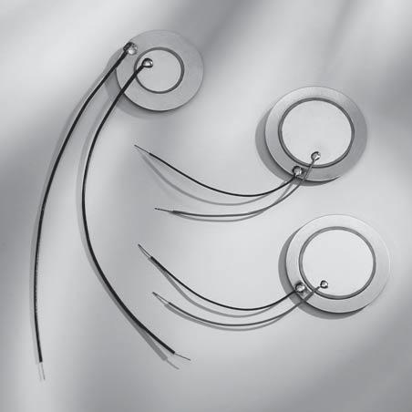
293
294 Piezokeramische Breitband- Signalgeber Piezoceramic Wide-Band Sounders Inhaltsverzeichnis / Contents Seite / Page Allgemeines General Piezokeramik-Schallgebermembrane Piezoceramic sound transducer membranes Piezokeramik-Breitband-Signalgeber Piezoceramic wide-band sounders Zertifiziertes QM-System: ISO/TS 16949:2002 ISO 9001:2000 Certified QM-System: ISO/TS 16949:2002 ISO 9001:
295 Allgemeines Piezokeramische Signalgeber finden heute in nahezu all den Fällen Anwendung, in denen Geräte und Einrichtungen dem Menschen eine akustische Information mitteilen müssen. SUMIDA liefert piezokeramische Signalgeber als Standardbauelemente sowie in kundenspezifischer Ausführung. Im einfachsten Fall besteht ein piezoelektrischer Signalgeber aus dem Verbund einer dünnen Piezokeramik mit einer Metallmembrane. Solche Schallgebermembrane sind das Kernstück aller Piezo-Akustikwandler. Durch Einbringen der Schallgebermembrane in ein Gehäuse werden die darin befindlichen Luftmassen mit der Membrane gekoppelt. Das eingeschlossene Luftpolster wirkt als Feder-Masse-System und erzeugt eine schwingende Luftsäule im Bereich der Resonatoröffnung. Die Signalgeber besitzen eine breitbandige Abstrahlcharakteristik und sind für eine große Anzahl unterschiedlicher Applikationen geeignet Unter "breitbandig" verstehen wir die Eigenschaft, Signale über einen möglichst weiten Tonfrequenzbereich bei relativ geringer Schalldruckdifferenz wiedergeben zu können. Als weiterer Vorteil dieser modernen Technik ergibt sich ein hoher Wirkungsgrad bei kleiner Baugröße. Die Schalldruckwerte sind je nach Typ im Freifeld oder auf einer definierten Meßplatte ermittelt. Bei der Montage innerhalb von Gehäusen und auf Leiterplatten unterschiedlicher Ausführung und Größe kann es zu akustischen Gesamtbedingungen kommen, die eine andere Frequenzcharakteristik zeigen als die von uns ermittelten Werte. Eine Optimierung unter Berücksichtigung der anwendungspezifischen Einbaubedingungen wird dem Anwender empfohlen. General Today piezoceramic sounders can be used in nearly all applications where devices and equipment have to yield acoustic information. SUMIDA supplies piezo-ceramic sounders as standard components and also according to customers` specification. The sounders have a wide-band characteristic and are therefore usable for a great variety of different applications. In the simple case the piezoelectric sounder is a compound of a thin piezoceramic plate with a metal diaphragm. Such sound-transducer-membranes are the main items of all piezo-sound-transducers. By positioning a sound-transducer-membrane in a housing the enclosed airmass will be coupled with this membrane. The indoor air cushion affects such a Clip-Mass-System and excites a swinging air column in the range of the resonatorhole. By "wide-band" we mean the ability to transmit signals over a frequency range which is as wide as possible, at a relative low sound pressure difference. A further advantage of this modern technology is a high efficiency with small sizes. The sound pressure values are measured in free-field or defined measuring boards acc. to type. Mounting in boxes and on printed boards of different types and sizes can result in acoustic conditions which show a frequency characteristic different from the values measured by us. We recommend the customer to consider his own application in order to reach the best conditions. All sounders are supplied in print design which can be easily mounted. Sämtliche Signalgeber werden in montagefreundlicher Printausführung geliefert
296 Ansteuerung von Signalgebern Die Ansteuerung der Signalgeber kann je nach Ansteuertyp mit dem Hauptspannungsnetz oder Batterie erfolgen. SUMIDA bietet dabei zwei folgende Typen: - Schallgebermembrane für selbstschwingenden Betrieb (Wechselstrom) - Schallgebermembrane für Fremdansteuerung (Wechselstrom) - Piezokeramik Breitbandsignalgeber für Fremdansteuerung (Wechselstrom) - Piezokeramik Breitbandsignalgeber für selbstschwingenden Betrieb (Gleichstrom) Die erzielbare Lautstärke, Schalldruckpegel SDP genannt, ist natürlich auch direkt abhängig von der Ansteuerspannung und folgt der Beziehung: Driving of sounders Depending on the drive type the sounders may be powered from the mains or by batteries. SUMDIA provides two circuit designs as follows: - Sound-transducer membranes for self drive elements (AC) - Sound-transducer membranes for external drive elements (AC) - Piezoceramic wideband sounders - external drive elements (AC) - Piezoceramic wideband sounders - self drive elements (DC) The loudness level which can be achieved - the so-called pressure level SPL - of course depends directly on the drive voltage and follows the formula: Ux Δ SDP = 20log U 0 [ db] U o Ansteuerspannung, für die der SDP bekannt ist (z.b. 12 Vss siehe Meßdaten). U x die höhere (oder niedrigere) zur Verfügung stehende Ansteuerspannung. SDP die Änderung in db, die der bekannte Schalldruckpegel SDP erfährt. U o the control voltage for which the SPL is known (for examples 12 Vp-p see measuring data). U x the higher (or lower) drive voltage available. SDP the change in db, applied to the known sound pressure level SPL
297 Piezokeramische Schallgebermembrane - für Fremdansteuerung (Wechselstrom) Piezoceramic Sound-Transducer Membranes - External Drive Element (AC)
298 B A C D C = Kapazität / Capacitance f = Resonanzfrequenz / Resonant frequency Z = Resonanzimpedanz / Resonant impedance Isolationswiderstand / Insulation resistance Ris: > 100 MΩ Max. Betriebsspannung / Max. operating voltage: Umax: 30 Vpp Standard-Keramik / Standard ceramic material: PZT SA Die Schallgeber sind auch mit einer zweiten Keramikscheibe erhältlich. Beim Serienbimorph ist die Polarisation in beiden Keramikscheiben entgegengesetzt; die Spannung wird an den Außenelektroden angelegt bzw. abgenommen. Diese Anordnung wird oft für Sensoren eingesetzt, da sich bei gleicher Auslenkung die abgreifbare Spannung verdoppelt im Vergleich zur Verwendung von nur einer Piezokeramikscheibe. Beim Parallelbimorph ist die Polarisation in beiden Keramikscheiben gleichsinnig; die Auslenkung erfolgt durch eine Spannung zwischen Mittenelektrode und den Außenelektroden. Diese Anordnung wird meist für Aktuatoren zum Reduzieren der Ansteuerspannung gewählt. Discs also available with second ceramic disc. The series bimorph consists of two plates polarized in opposite directions and can be contacted at the outer electrodes. It is the preferred type for sensors, because voltage is doubled for same displacement compared to a disc with just one piezo. The parallel bimorph consists of two plates polarized in the same direction. A parallel connection is made by contacting inner and outer electrode. That is the preferred type for actuators because the driving voltage is reduced. Serienbimorph / serial bimorph Bestellbezeichnung z.b.: SS 23 - JHR S Auf Anfrage sind folgende Variationen lieferbar: > isolierende Schutzlackschicht auf Keramik > weitere Kombinationen von Metall- und Keramikscheibe > Anschlüsse mit Litzen AWG 30 oder AWG 28 Bestellbezeichnung für Anschlüsse z.b.: Scheibe mit 50 mm langer Litze SS 23 - JHR Bitte geben Sie an, ob AWG 28 oder 30 gewünscht wird. Parallelbimorph / parallel bimorph Ordering number e.g.: SS 23- Jhr P Following variations on request: > protective lacquer on ceramic disc > other combinations of metal and ceramic disc > terminals with wire AWG 30 or AWG 28 Ordering number for terminals e.g.: Disc with terminal of 50 mm in length SS 23 - JHR Please note if you wish AWG 28 or 30. A B Rot / red Schwarz / black
299 Piezokeramische Schallgebermembrane - für selbstschwingenden Betrieb (Wechselstrom) Piezoceramic Sound-Transducer Membranes - Self Drive Element (AC) Typ / Type C0 [nf] Cf [nf] f [khz] Z [Ω] Abmessungen / Dimensions [mm] A B C D Metallscheibe / Metal Disc SS 12-7DN-000-F 12 2,5 5, ,05 0,11 Messing / Brass SS 15-9FR-000-F 13 1, ,1 0,21 Messing / Brass SS 20-9HP-000-F 30 3,5 3, ,1 0,19 Messing / Brass SS 20-9HQ-000-F , ,1 0,2 Messing / Brass SS 20-9HS-000-F 25 2,7 3, ,1 0,22 Messing / Brass SS 20-HHS-000-F 18 2, ,12 0,24 Messing / Brass SS 20-0HS-000-F 25 2,7 4, ,15 0,27 Messing / Brass SS 21-9HP-000-F 33 3,5 3, ,1 0,19 Messing / Brass SS 21-9HS-000-F 18 2,5 3, ,1 0,22 Messing / Brass SS 21-0HS-000-F 25 2, ,15 0,27 Messing / Brass SS 27-0KT-000-F 24 2,4 2, ,15 0,31 Messing / Brass SS 27-0KU-000-F 30 3, ,15 0,32 Messing / Brass SS 27-JKT-000-F 31 3,4 3, ,1 0,26 Stahl / Steel SS 27-AKU-000-F , ,2 0,37 Messing / Brass SS 27-AKV-000-F 24 2,7 3, ,2 0,41 Messing / Brass SS 27-AKX-000-F 21 2,4 3, ,2 0,44 Messing / Brass SS 27-BKY-000-F 21 2,3 4, ,25 0,51 Messing / Brass SS 27-BKY2-000-F 16 1,9 4, ,25 0,51 Messing / Brass SS 27-PKX-000-F 22 1,8 4, ,25 0,49 Stahl / Steel SS 31-QKV-000-F 25 2,7 2, ,2 0,41 Stahl / Steel SS 35-JLS-000-F 68 7,8 1, ,1 0,22 Stahl / Steel SS 35-QLT-000-F 50 6,2 2, ,2 0,36 Stahl / Steel SS 35-ALX-000-F 38 4,2 2, ,2 0,44 Messing / Brass SS 35-BLZ-000-F 28 2,2 2, ,25 0,44 Messing / Brass SS 35-BLX-000-F , ,25 0,49 Messing / Brass SS 35-DLY-000-F 36 4,4 2, ,3 0,56 Messing / Brass SS 35-ULY-000-F , ,3 0,56 Stahl / Steel SS 35-WLT-000-F 35 4,2 3, ,4 0,56 Stahl / Steel SS 41-ALX-000-F 35 4,6 1, ,2 0,44 Messing / Brass SS 50-ALX-000-F 37 3,8 3, ,2 0,44 Messing / Brass SS 50-QMT-000-F ,2 0,36 Stahl / Steel SS 50-AMV-000-F , ,2 0,41 Messing / Brass
300 B A C D C 0 = Kapazität der Elektrode / Capacitance of electrode C f = Kapazität der Rückkoppelelektrode / Capacitance of feedback electrode f = Resonanzfrequenz / Resonant frequency Z = Resonanzimpedanz / Resonant impedance Isolationswiderstand / Insulation resistance Ris: > 100 MΩ Max. Betriebsspannung / Max. operating voltage: Umax: 30 Vpp Auf Anfrage sind folgende Variationen lieferbar: > isolierende Schutzlackschicht auf Keramik > Metallscheiben mit Arretierungskerben oder -flächen > weitere Kombinationen von Metall- und Keramikscheibe > Anschlüsse mit Litzen AWG 30 Bestellbezeichnung für Anschlüsse z.b.: Scheibe mit 50 mm langer Litze SS 23 - JHR F Following variations on request: > protective lacquer on ceramic disc > metal disc with slot or area for adjustment > other combinations of metal and ceramic disc > terminals with wire AWG 30 Ordering number for terminals e.g.: Disc with terminal of 50 mm in length SS - 23 JHR F A B rot/red blau/blue schwarz/black
301 Piezokeramik-Breitband-Signalgeber für Fremdansteuerung (Wechselstrom) TYP PS E Piezoceramic Wideband Sounders - External Drive Elements (AC) TYPE PS E SDP / SPL Schalldruckpegel SDP als Funktion von der Frequenz f Sound Pressure Level SPL as a function of the frequency f f / f Elektrische Bedingungen Electrical Specifications: Nennspannung Rated Voltage 12Vp-p Square Wave Max. Betriebsspannung Max. allowable Voltage 30Vp-p Square Wave Max. Nennstrom Max. Rated Current 4mA at 4.0 khz / 12Vp-p Square Wave Min. Schalldruckpegel Min. Sound Pressure Level 80dB at 4.0 khz / 12Vp-p Square Wave / 10cm Kapazität bei 120 Hz Capacitance at 120 Hz 9.5 nf Resonanzfrequenz Resonant Frequency 4.0 ±0,5 khz Betriebstemperatur Operating Temperature C Gewicht Weight 1g
302 TYPE PS E
303 TYP PS E TYPE PS E SDP / SPL Schalldruckpegel SDP als Funktion von der Frequenz f Sound Pressure Level SPL as a function of the frequency f f / f Elektrische Bedingungen Electrical Specifications: Nennspannung Rated Voltage 12Vp-p Square Wave Max. Betriebsspannung Max. allowable Voltage 30Vp-p Square Wave Max. Nennstrom Max. Rated Current 3mA at 4.0 khz / 12Vp-p Square Wave Min. Schalldruckpegel Min. Sound Pressure Level 88dB at 4.0 khz / 12Vp-p Square Wave / 10cm Kapazität bei 120 Hz Capacitance at 120 Hz 15 nf ±30 % Resonanzfrequenz Resonant Frequency 4.0 ±0,5 khz Betriebstemperatur Operating Temperature C Gewicht Weight 2.5g
304 TYP PS E TYPE PS E SDP / SPL Schalldruckpegel SDP als Funktion von der Frequenz f Sound Pressure Level SPL as a function of the frequency f f / f Elektrische Bedingungen Electrical Specifications: Nennspannung Rated Voltage 3Vms Sine Wave Max. Betriebsspannung Max. allowable Voltage 30Vp-p Square Wave Max. Nennstrom Max. Rated Current 2 ma at 2.0 khz / 3Vms Sine Wave Min. Schalldruckpegel Min. Sound Pressure Level 75dB at 2.0 khz / 3Vms Sine Wave / 10cm Kapazität bei 120 Hz Capacitance at 120 Hz 30 nf ±30 % Resonanzfrequenz Resonant Frequency 2.0 ±0,5 khz Betriebstemperatur Operating Temperature C Gewicht Weight 3g
305 Piezokeramik-Breitband-Signalgeber - selbstschwingenden Betrieb (Gleichstrom) - TYP PS S Piezoceramic Wideband Sounders - Self Drive Elements (DC) - TYPE PS S Elektrische Bedingungen Electrical Specifications: Nennspannung Rated Voltage 12 VDC Max. Betriebsspannung Max. allowable Voltage 3-24 VDC Max. Nennstrom Max. Rated Current 25 ma at 3,5 khz / 12 VDC Min. Schalldruckpegel Min. Sound Pressure Level 85dB at 3,5 khz / 12 VDC / 10 cm Resonanzfrequenz Resonant Frequency 3,5 ± 0,5 khz Betriebstemperatur Operating Temperature -20~ +80 C Gewicht Weight 4g Tonart Tone Nature andauernd / continuous
306 TYP PS S TYPE PS S Elektrische Bedingungen Electrical Specifications: Nennspannung Rated Voltage 6-15 VDC Max. Betriebsspannung Max. allowable Voltage 15 VDC Max. Nennstrom Max. Rated Current 16 ma at 9 VDC Min. Schalldruckpegel Min. Sound Pressure Level 90dB at 9 VDC / 30 cm Resonanzfrequenz Resonant Frequency 3.4 ±0.5 khz Betriebstemperatur Operating Temperature -20~ +80 C Gewicht Weight 13g Tonart Tone Nature andauernd / continuous
307
 / Distributors (D) - worldwide - 308")
308 Unsere Vertretungen (R) /Distributoren (D) - weltweit Our Representatives (R) / Distributors (D) - worldwide
0603 drahtgewickelt (AgPd/Ni/Sn Metallisierung) 0603 wire-wound (AgPd/Ni/Sn Metallisation)
 0603 wire-wound (AgPd/Ni/Sn Metallisation)") 0603 drahtgewickelt (AgPd/Ni/Sn Metallisierung) 0603 wire-wound (AgPd/Ni/Sn Metallisation) - 22 - Allgemeine Eigenschaften zu den drahtgewickelten SMD-Spulen Bauform 0603 / Baureihe 5406 STELCO erweitert
0603 drahtgewickelt (AgPd/Ni/Sn Metallisierung) 0603 wire-wound (AgPd/Ni/Sn Metallisation) - 22 - Allgemeine Eigenschaften zu den drahtgewickelten SMD-Spulen Bauform 0603 / Baureihe 5406 STELCO erweitert
Produktspektrum Chipspulen Product Spectrum Chip Coils
 Produktspektrum Chipspulen Product Spectrum Chip Coils Induktivität Inductance 1,0 nh - 220 nh 0603 laser 470 0603 0603 1,5 nh - nh 470 nh - 2700 nh 2,7 nh - 820 nh 680 nh - 4700 nh 0805 0805 10 nh -1200
General Information. Allgemeines - 87 - Aufbau. Constructional features
 Allgemeines General Information Aufbau - Quaderförmiger Körper aus Ferritmaterial - Baugröße 1008 - Vier lötfähig metallisierte Kontaktierungsflächen - Wicklung: Kupferlackdraht - Wicklungsenden auf den
INDUCTORS CAPACITORS PIEZO CERAMICS
 INDUCTORS CAPACITORS PIEZO CERAMICS Firmenprofil Wir sind ein traditionsreicher Hersteller passiver elektronischer Komponenten mit Sitz in Neumarkt i. d. Opf. Die im Dezember 1999 gegründete STELCO GmbH
Übertrager 1008 Chip Transformer 1008
 Übertrager 1008 Chip Transformer 1008 Inhaltsverzeichnis / Contents Seite / Page Allgemeines 86-88 General Information Applikationshinweise 89 Application Guide Gleichsinnige Wicklung 90-91 Equal winding
Produktspektrum Chipspulen / Product Spectrum Chip Coils
 Allgem Allgem Produktspektrum Chipspulen / Product Spectrum Chip Coils 1,0 nh - 100nH 0402 laser 1,0 nh - 220 nh 0603 laser 1,5 nh - 390 nh 0603 2,7 nh - 820 nh 0805 0805 680 nh - 4700 nh 10 nh -1200 nh
HR SMT Chipinduktivitäten 0603 / 0805 für höchste Zuverlässigkeitsanprüche HR SMT Chip Inductors 0603 / 0805 for High Reliability Market
 HR SMT Chipinduktivitäten 0603 / 0805 für höchste Zuverlässigkeitsanprüche HR SMT Chip Inductors 0603 / 0805 for High Reliability Market fotolia.com Zertifiziertes QM-System: ISO/TS 16949 Version 3 ISO
Übertrager 1008 Chip Transformer 1008
 Übertrager 1008 Chip Transformer 1008-61 - Übertrager 1008 Chip Transformer 1008 Inhaltsverzeichnis / Contents Seite / Page Allgemeines 63-65 General Information Applikationshinweise 66 Application Guide
Sizes - Series. Features: Applications:
 Drahtgewickelte SMD-Spulen Diese Baureihe zeichnet sich durch ein exzellentes Preis-/ Leistungsverhältnis aus. Für Systemlieferanten der Elektronikindustrie bietet Stelco s E-Serie eine sehr kosteneffiziente
SIMID 1210-100. Size 1210 (EIA) or 3225 (IEC) Rated inductance 0,0082 to 100 µh Rated current 65 to 800 ma
 or 3225 (IEC) Rated inductance 0,0082 to 100 µh Rated current 65 to 800 ma") Size 12 (EIA) or 3225 (IEC) Rated inductance 0,0082 to 0 µh Rated current 65 to 800 ma Construction Ceramic or ferrite core Laser-welded winding Flame-retardant encapsulation Features Very wide temperature
Size 12 (EIA) or 3225 (IEC) Rated inductance 0,0082 to 0 µh Rated current 65 to 800 ma Construction Ceramic or ferrite core Laser-welded winding Flame-retardant encapsulation Features Very wide temperature
336 Wannenstiftleisten RM 1,27mm, gerade/gewinkelt Box Headers, 1.27mm Pitch, Straight/Right-Angled
 Technische Daten / Technical Data Isolierkörper Thermoplastischer Kunststoff, nach UL94 V-0 Insulator Thermoplastic, rated UL94 V-0 Kontaktmaterial Messing Contact Material Brass Kontaktoberfläche Vergoldet
EMI Suppression Capacitors X2 / 275 and 300 Vac B3292 B32922 X2 MKP/SH 40/100/21/C
 EMI Suppression Capacitors X2 / 275 and 300 Vac B3292 X2 capacitors with very small dimensions Rated ac voltage 275 and 300 V, 50/60 Hz Construction Dielectric: polypropylene (MKP) Plastic case (UL 94
Ceramic tubular trimmer capacitors with metal spindle for PCB mounting
 Keramik-Rohrtrimmer-Kondensatoren mit Metallspindel für gedruckte Schaltungen Mit metallischen Anschlussarmaturen im Raster, für den Abgleich senkrecht oder parallel zur Leiterplattenebene. Ceramic tubular
Taster gerade - Einlöt / SMT / Kappen Straight Tact Switches - Solder-in / SMT / Caps
 Technische Daten /Technical Data Gehäuse/Abdeckung/Hebel Thermoplastischer Kunststoff, nach UL94 V-0 Rostfreier Stahl Thermoplastischer Kunststoff, nach UL94 V-0 Case/Cover/Actuator Thermoplastic, rated
114-18867 09.Jan 2014 Rev C
 Application Specification 114-18867 09.Jan 2014 Rev C High Speed Data, Pin Headers 90 / 180 4pos., shie lded High Speed Data, Stiftleiste 90 / 180, geschirmt Description Beschreibung 1. Packaging of pin
Verarbeitungsspezifikation Application Specification. Verarbeitungsspezifikation. Application Specification MA-59V093. für for. Winkelstecker für PCB
 Verarbeitungsspezifikation MA-59V093 für for Winkelstecker für PCB Right angle plug for PCB 59S2AF-40MXX-Y 59S2LF-40MXX-Y 59S2RF-40MXX-Y 59S2UF-40MXX-Y 200 09-0100 U_Winkler 11.02.09 100 08-v323 U_Winkler
Durchführungskondensatoren mit Anschlußdraht Feedthrough capacitors with pin. Baureihe / Series
 Durchführungskondensatoren mit Anschlußdraht Feedthrough capacitors with pin Baureihe / Series BDBQ 3-01 2709 BUBQ 5-00 2701 BDBQ 5-00 2701 BDBQ 5-12 2701 BDBQ 5-02 2701 LUEQ 6-01 2703 LDEQ 6-01 2703 DDMN
B81133 X2 MKT/SH 40/100/21/C B81133 X2 MKT/SH 40/100/21/C. EMI Suppression Capacitors X2 / 275 Vac Not for new design
 EMI Suppression Capacitors X2 / X2 capacitors with small dimensions Rated ac voltage 275 V, 50/60 Hz 1) Construction Dielectric: polyester (MKT) Internal series connection Plastic case (UL 94 V-0) Epoxy
EMI Suppression Capacitors X2 / 275 Vac
 EMI Suppression Capacitors X2 / B81130 X2 capacitors with very small dimensions Rated ac voltage 275 V, 50/60 Hz Construction ielectric: polypropylene (MKP) Plastic case (UL 94 V-0) Epoxy resin sealing,
Kuhnke Technical Data. Contact Details
 Kuhnke Technical Data The following page(s) are extracted from multi-page Kuhnke product catalogues or CDROMs and any page number shown is relevant to the original document. The PDF sheets here may have
THT/THR Connectors THT/THR Steckverbinder
 Contact Cambridge Connectors. Phone +44 1223 860041 Email: sales@cambridgeconnectors.com THT/THR Connectors THT/THR Steckverbinder Ordering Code Bestellschlüssel ALL DIMENSIONS IN MILLIMETERS - VALUES
FMC. 52 Rosenberger Hochfrequenztechnik GmbH & Co. KG, Germany, Phone +49 (0)8684 18-0, info@rosenberger.de, www.rosenberger.com
8684 18-0, info@rosenberger.de, www.rosenberger.com") The extremely small FMC connector series Flexible Microstrip Connectors are designed for PCB applications in the tightest spaces. Using bullets, equalization of radial and axial misalignments in board-to-board
The extremely small FMC connector series Flexible Microstrip Connectors are designed for PCB applications in the tightest spaces. Using bullets, equalization of radial and axial misalignments in board-to-board
Inductors for Power Electronics Induktivitäten für die Leistungselektronik
 EN DE 2015/16 Edition 1 Ausgabe 1 Inductors for Power Electronics Induktivitäten für die Leistungselektronik BLOCK custom and standard products BLOCK Sonderlösungen und Standardprodukte inductors MADE
GTP - Permanent Elektro Haftmagnet. GTP - Permanent Electro Magnet
 GTP - GTP - GTP GTP Übersicht overview Baureihe Dimensionen FHalte GTP-20 Ø20 x 22 70 GTP-30 Ø30 x 32 130 GTP-34 Ø34 x 39.6 260 GTP-60 Ø60 x 53.5 620 Type Dimensions Fholding GTP-20 Ø20 x 22 70 GTP-30
Würth Elektronik ibe Automotive solutions
 Würth Elektronik ibe Automotive solutions Juli 2016 Seite 1 Die Würth Gruppe Die Würth Unternehmensgruppe Über 69.000 Mitarbeiter, 11 Mrd. Umsatz Über 400 Unternehmen In über 80 Ländern Die Würth Elektronik
D-Sub Dualport Steckverbinder D-Sub dualport connectors
 D-Sub Dualport Steckverbinder D-Sub dualport connectors Bestellschlüssel Ordering code ALL DIMENSIONS IN MILLIMETERS - VALUES FOR INCHES IN BRACKETS - TECHNICAL DATA SUBJECT TO CHANGE 73 Technische Daten
Chokes and Inductors Drosseln und Induktivitäten
 Product Profile 2007 Chokes and Inductors Drosseln und Induktivitäten www.epcos.com Welcome to the World of Electronic Components With its broad portfolio in electronic components EPCOS provides one-stop
high potential insulating transformer Hochpotenzial- Trenntrafo bis 80 kv Potenzialtrennung up to 80 kv potential difference Tauscher Transformatoren
 Hochpotenzial - Hochspannungs - Trenntransformatoren pri - sec und einer Leistung von 1 VA bis 3000 VA Isoliertrafo, Isolationstransformator Einsatzmöglichkeiten Hochspannungstrenntransformatoren werden
GTP - Permanent Elektro Haftmagnet Datenblätter. GTP - Permanent electro magnet Datasheets
 GTP - Datenblätter GTP - Datasheets GTP GTP Übersicht overview Übersicht / Overview Typ Type Dimensionen Dimensions [mm] F Haft F Holding [N] GTP-20 Ø20 x 22 70 GTP-30 Ø30 x 32 130 GTP-34 Ø34 x 39.6 260
direktgesteuert direct acting
 1 direktgesteuert direct acting Schaltfunktion A: function A: NC (stromlos geschlossen) NC (normally closed) Schaltfunktion B: function B: NO (stromlos offen) NO (normally open) Bauart Kolbenventil Nennweite
The following products presented in this data sheet are being withdrawn. B66414B6008T002 2003-08-08 2004-02-29 2004-08-31
 EFD/EV/DE Cores Series/Type: EFD /8/ The following products presented in this data sheet are being withdrawn. Ordering Code Substitute Product Date of Withdrawal Deadline Last Orders Last Shipments B66B6008T002
diameter DN 2,0 6,0 0 max. 48bar (see table) body material brass, AISI 303, AISI 316
 body material brass, AISI 303, AISI 316") direktgesteuert direct acting Schaltfunktion A: function A: NC (stromlos geschlossen) NC (normally closed) Schaltfunktion B: function B: NO (stromlos offen) NO (normally open) Bauart Sitzventil Nennweite
direktgesteuert direct acting Schaltfunktion A: function A: NC (stromlos geschlossen) NC (normally closed) Schaltfunktion B: function B: NO (stromlos offen) NO (normally open) Bauart Sitzventil Nennweite
FMC. Features. Product Range
 The extremely small FMC connector series Flexible Microstrip Connectors are designed for PCB applications in the tightest spaces. Using bullets, equalization of radial and axial misalignments in board-to-board
Compressed air - dewpoint 10K under ambient temperature - ISO8573-1, Kl. 3 Durchflussrichtung Flow direction EIN: von 1-2 AUS: von 2 3
 3/2 Wegeventil mit PIEZO-Pilotventil Baureihe P20 3/2 way valve with Piezo-pilot valve Series P20 P20 381RF-* NW 2 Eigenerwärmungsfrei Ein Produkt für alle Ex-Bereiche Kompatibel zu Microcontrollern Kompatibel
VDE Prüf- und Zertifizierungsinstitut Zeichengenehmigung
 Blatt / page 2 Dieses Blatt gilt nur in Verbindung mit Blatt 1 des sausweises Nr.. This supplement is only valid in conjunction with page 1 of the. Einbauteil für IT Geräte Component for IT equipment Typ(en)
ISA-PLAN - Precision Resistor Type PBV
 ISA-PLAN - Precision Resistor Type PBV Spec Sheet R361-1/2 July 97 Technical Data Resistance range 0.5 mohm - 1 Ohm Tolerances 0.5 %, 1 %, 5 % Temperature coefficient ( R > 10 mohm ) < 30 ppm/k ( 20 C
Hochstrom-Druckkontakte für Dauerströme bis 400 A. High Current Probes up to 400 amps cont. Ausgabe 7/2009 DE EN. Edition 7/2009 DE EN
 Hochstrom-Druckkontakte für Dauerströme bis 400 usgabe 7/2009 DE EN High Current Probes up to 400 amps cont. Edition 7/2009 DE EN Impressum und Bestellhinweise Company and Ordering Information Unsere
Technical Specification. Technische Spezifikation
 Technical Technische Technical Schurter s range of "Audio, DC and DIN Connectors" offers a cost effective solution for a wide range of applications. Technische Schurter s Sortiment an Audio, DC und DIN
Verarbeitungsspezifikation Application Specification. Verarbeitungsspezifikation. Application Specification MA_59V054. für for. Leiterplattenstecker
 Verarbeitungsspezifikation MA_59V054 für for Leiterplattenstecker plug for PCB 59S2AA-400XX-Y 59S2AA-400XX-Y DR Ehrensch. H. 07.02.2005 CHK Rosenberger Hochfrequenztechnik D-84526 Tittmoning 200 07-0304
Aderendhülsen Ferrules
 Aderendhülsen Ferrules 1 Aderendhülsen Ferrules Seite Page Allgemeine Informationen General information 11 Aderendhülsen, Einzelbeutel Insulated ferrules, single bag 12 Aderendhülsen, Bandware Insulated
Quarz Bauelemente. Communicate to Win.
 Quarz Bauelemente Communicate to Win. CRYSTAL RESONATORS (SMD Type) 1612 Series 211 Series 221 Series 321 Series Ultra miniature and lightweight SMD crystal resonator with a low profile of 0.30 mm High
Deceleration Technology. Rotary Dampers with high-torque range WRD-H 7550 WRD-H 9565 WRD-H
 Rotary Dampers with high-torque range WRD-H 7550 WRD-H 9565 WRD-H 12070 Deceleration Technology ONLINE CALCULATION AND 2D / 3D CAD DOWNLOAD M m L F Benefits Material: - Aluminium and steel Applications:
MCX (50 Ω) - Mikrominiatur- Koaxialsteckverbinder für Anwendungen bis 6 GHz. (50 Ω) - Microminiature Coaxial Connectors for Frequencies up to 6 GHz
 - Mikrominiatur- Koaxialsteckverbinder für Anwendungen bis 6 GHz. (50 Ω) - Microminiature Coaxial Connectors for Frequencies up to 6 GHz") MCX 3 MCX (50 Ω) MCX (50 Ω) 1MCX (50 Ω) (50 Ω) - Microminiature Coaxial Connectors for Frequencies up to 6 GHz MCX - optimal connector series, provided with a snap- on connecting system like SMB connectors,
MCX 3 MCX (50 Ω) MCX (50 Ω) 1MCX (50 Ω) (50 Ω) - Microminiature Coaxial Connectors for Frequencies up to 6 GHz MCX - optimal connector series, provided with a snap- on connecting system like SMB connectors,
г.минск тел.8(017) DD 400 S 17 K6 B2 RMS, f = 50 Hz, t = 1 min. V ISOL 4 kv
 DD 400 S 17 K6 B2 RMS, f = 50 Hz, t = 1 min. V ISOL 4 kv") Höchstzulässige Werte / Maximum rated values Periodische Spitzensperrspannung repetitive peak reverse voltage Dauergleichstrom DC forward current V CES 1700 V I F 400 A Periodischer Spitzenstrom repetitive
Höchstzulässige Werte / Maximum rated values Periodische Spitzensperrspannung repetitive peak reverse voltage Dauergleichstrom DC forward current V CES 1700 V I F 400 A Periodischer Spitzenstrom repetitive
Bewickelte Widerstandsrohre Wire-Wound Resistor Tubes
 Bewickelte Widerstandsrohre Wire-Wound Resistor Tubes Bewickelte Widerstandsrohre 50 bis 2050 Watt* fixiert und gegen äußere mechanische inflüsse geschützt. Außerdem wird dadurch die Wärmeableitung verbessert.
CONTROLLER RECEIVER REPEATER PAIRING SLIM CLIP
 ANLEITUNGEN // INSTRUCTIONS CONTROLLER RECEIVER REPEATER PAIRING SLIM CLIP BEDIENUNGSANLEITUNG // INSTRUCTION MANUAL MONTAGEANLEITUNG // ASSEMBLY INSTRUCTION MONTAGEANLEITUNG // ASSEMBLY INSTRUCTION KOPPLUNG
DC/DC Converter 400 W
 Eingangsbereich 4 : 1 Input Range 4 : 1 Wirkungsgrad bis 90 % Efficiency up to 90 % Full Brick Gehäuse Full Brick Case Eingangs-π-Filter Input-π-Filter Beschreibung 10 DC/DC-Wandler stehen in der Serie
0,5 max. 16bar (see table) body material brass, AISI 303, AISI 316
 body material brass, AISI 303, AISI 316") servogesteuert pilot operated Schaltfunktion A: function A: NC (stromlos geschlossen) NC (normally closed) Schaltfunktion B: function B: NO (stromlos offen) NO (normally open) Bauart Nennweite DN 13 50
servogesteuert pilot operated Schaltfunktion A: function A: NC (stromlos geschlossen) NC (normally closed) Schaltfunktion B: function B: NO (stromlos offen) NO (normally open) Bauart Nennweite DN 13 50
Technische Änderungen vorbehalten / modifications reserved Stand / stand: 11/2011
 zwangsgesteuert force pilot operated Schaltfunktion A: function A: NC (stromlos geschlossen) NC (normally closed) Schaltfunktion B: function B: NO (stromlos offen) NO (normally open) Bauart Nennweite DN
spacing GEO Detector: Schmitt-Trigger IC SFH 9240: Output active low
 Reflexlichtschranke im P-DSO-6-Gehäuse Reflective Interrupter in P-DSO-6 Package Vorläufige Daten / Preliminary Data 0.5 0. 6.2 5.8.4.0 0...0. 2..7 4.2.8 6 2 5 4 0.5 0..27 spacing GEO06840 Type 2 4 5 6
fastpim 1 H fast switching H bridge module Features: - 1 Phase Input Rectifier Bridge - 1 Phase fast switching IGBT + FRED full H bridge - NTC
 fast switching H bridge module Features: - 1 Phase Input Rectifier Bridge - 1 Phase fast switching IGBT + FRED full H bridge - NTC Copyright by Vincotech 1 Revision: 1 module types / Produkttypen Part-Number
Kuhnke Technical Data. Contact Details
 Kuhnke Technical Data The following page(s) are extracted from multi-page Kuhnke product catalogues or CDROMs and any page number shown is relevant to the original document. The PDF sheets here may have
Bleifreie Bauteile bei Diotec Lead Free Products at Diotec
 Bleifreie Bauteile bei Diotec Lead Free Products at Diotec 1 Bleifreie Bauteile Gesetzliche Grundlage Leadfree Devices Legislation 2 Ausnahmeregelungen in den Richtlinien, Bsp. 2002/95/EG - ROHS Exemptions
We are pleased to inform you that the addendum this requires to the existing product approval has now been successfully completed.
 MSA AUER GmbH! Thiemannstraße 1! D-12059 Berlin To our customers Name Phone, Fax E-mail Date Malte Kaas (030) 6886-0, -1613 Malte.Kaas@MSAsafety.com 10.12.2014 Duracell MN 1500 Procell Retail availability
drawbar eye series 2010
 drawbar eye series 2010 directive 94/20/EG / class S DIN 74054-40A / material St52-3 (no. 1.0570) / with bush 40 mm parameters for centre-axle trailer s ṣhaft cross section order no H x B mm length A mm
Produktdatenblatt. Artikel Nr.: Wandaufbauleuchte, Alpha II, Weiß, V AC/50-60Hz, 100,00 W. Technische Daten.
 Produktdatenblatt Artikel Nr.: 341107 Wandaufbauleuchte, Alpha II, Weiß, 220-240V AC/50-60Hz, 100,00 W Technische Daten Charakteristik Material Farbe Weiß Optik im Lieferumfang Elektrische Daten Leistung
Application Specification. MINI USB B USCAR30 Headers & Harnesses 1. GENERAL / ALLGEMEIN... 2
 Application Specification 114-94128 12 th March 2012 Rev A2 MINI USB B USCAR30 Headers & Harnesses CONTENT / INHALT 1. GENERAL / ALLGEMEIN... 2 2. TEC-COMPONENTS / TEC- KOMPONENTEN... 2 2.1 90 SMT HEADER...
Mikro-Magnetventile Typ 65 NW 0,5/1/1,6/2 2/2- und 3/2-Wege Sitzventile Direktgesteuert
 NW 0,//,6/ /- und /-Wege Sitzventile 0.//.6/ mm Orifice /- and /-Way Poppet Valves Als Standard sind die Ventile in vielfältigen Ausführungen lieferbar, z.b. drei unterschiedliche Sockelformen (Standard-,
UV-MASTER. Härtung von Foliendekoroberflächen mit UV-Strahlung UV-Curing of film decorated mold parts (IMD/IML)
") UV-MASTER Härtung von Foliendekoroberflächen mit UV-Strahlung UV-Curing of film decorated mold parts (IMD/IML) OBERFLÄCHEN-REINIGUNGS-SYSTEME SURFACE-CLEANING-SYSTEMS UV-MASTER UV-HÄRTUNG von Design-Folien
UV-MASTER Härtung von Foliendekoroberflächen mit UV-Strahlung UV-Curing of film decorated mold parts (IMD/IML) OBERFLÄCHEN-REINIGUNGS-SYSTEME SURFACE-CLEANING-SYSTEMS UV-MASTER UV-HÄRTUNG von Design-Folien
Pneu. Linearantriebe mit externer Gleitführung Baureihe PLS
 Pneu. Linearantriebe mit externer Gleitführung Baureihe PLS Linearführung mit externer Gleitführung im Profil Linear guide with external gliding carriage on the profil Typ PLS/...zum Anbau an Linearzylinder
BPX 80 BPX NPN-Silizium-Fototransistor Zeilen Silicon NPN Phototransistor Arrays BPX 80 BPX
 NPN-Silizium-Fototransistor Zeilen Silicon NPN Phototransistor Arrays BPX 80 Maße in mm, wenn nicht anders angegeben/dimensions in mm, unless otherwise specified. feo06367 fez06365 Wesentliche Merkmale
Motorenreihe Einphasen Wechselstrom
 Einphasen Wechselstrommotorensingle phase motors enreihe Einphasen Wechselstrom line single-phase Eckdaten Key data n s Gehäusematerial Frame material Number of poles Leistung Output 63 bis 100 63 to 100
Bayerisches Landesamt für Gesundheit und Lebensmittelsicherheit Pool water quality the German philosophy
 Bayerisches Landesamt für Gesundheit und Lebensmittelsicherheit Pool water quality the German philosophy Christiane Höller Bavarian Health and Food Safety Authority Legal regulations 1979 Federal Law on
Order Number Bestellnummer. Hand crimp tool Handcrimpzange Positioner Einsatz Positioner Einsatz. Order Number. Bestellnummer
 Crimpingtools for Miniature Connectors Crimpwerkzeuge für Miniatursteckverbinder Hand Crimp Tool M22520/2-01 for Machined Contacts Handcrimpzange M22520/2-01 für gedrehte Kontakte Die / Einsatz Hand crimp
Hydra-Motorkondensatoren für Wechselstrommotoren MKP-Technologie Reihe 400 Sicherheitsklasse P0
 400 für Wechselstrommotoren Sicherheitsklasse P0 for AC Motors safety class P0 400 Inhalt contents Typenbezeichnung....................................3 - trockene Bauweise -................................4
Distanzmontageteilen. Distance rolls
 Distanzmontageteile Distance rolls Finger - and U-shaped Attachables with solderpins with solderpin standard length h Profiles Retaining Mounting springs accessories accessories Distance spacers Fans Technical
Klein-Magnete ziehend, stossend, Doppel- oder Umkehrhub für Gleichstrom. Small Solenoids pull or push, double or return operation DC Solenoids
 Klein-Magnete,, Doppel- oder für Gleichstrom Small Solenoids pull or push, DC Solenoids 3 Doppel- oder ISLIKER MAGNETE AG Tel. ++41 (0)52 305 25 25 CH-8450 Andelfingen Fax ++41 (0)52 305 25 35 Switzerland
INSTALLATION AND OPERATING INSTRUCTIONS FOR LPS203-M LPS203-M 操 作 指 示
 BEDIENUNGSANLEITUNG To comply with the published safety standards, the following must be observed when using this power supply. Um den zur Zeit gültigen Sicherheitsbestimmungen zu genügen, müssen die nachstehenden
Dickfilm-Widerstände Thick-Film Resistors
 Dickfilm-Widerstände Thick-Film Resistors Dickfilm-Widerstände werden universell eingesetzt: in der Uhrenindustrie, Kommunikations-/Datentechnik,... bis hin zur Kfz-Elektronik. Verwendung finden die Baugrößen
IDC Ribbon Connectors Flachbandkabelsteckverbinder. Product Description Produktbeschreibung
 IDC Ribbon Connectors Product Description Produktbeschreibung Advantages and Special Features Connector with IDC-contacts for termination of IDC Ribbon cables Available in sizes -way to 7-way With strain-relief
Schnelle GaAs-IR-Lumineszenzdiode (950 nm) High-Speed GaAs Infrared Emitter (950 nm) SFH 4200 SFH 4205
 High-Speed GaAs Infrared Emitter (950 nm) SFH 4200 SFH 4205") Schnelle GaAs-IR-Lumineszenzdiode (95 nm) High-Speed GaAs Infrared Emitter (95 nm) SFH 42 SFH 425 SFH 42 SFH 425 Wesentliche Merkmale GaAs-LED mit sehr hohem Wirkungsgrad Gleichstrom- (mit Modulation)
Schnelle GaAs-IR-Lumineszenzdiode (95 nm) High-Speed GaAs Infrared Emitter (95 nm) SFH 42 SFH 425 SFH 42 SFH 425 Wesentliche Merkmale GaAs-LED mit sehr hohem Wirkungsgrad Gleichstrom- (mit Modulation)
2 NEUHEITEN - NEWS 2014. MPE-Garry interconnecting your ideas
 NEUHEITEN - NEWS 2014 2 NEUHEITEN - NEWS 2014 MPE-Garry interconnecting your ideas 712 Micro-USB-Steckverbinder in SMD-Ausführung Micro-USB-Connectors in Surface Mount Version Board termination Material
Technische Änderungen vorbehalten / modifications reserved Stand / stand: 11/2011
 direktgesteuert mit PTFE-Faltenbalg direct acting with PTFE-bellow Schaltfunktion A: function A: NC (stromlos geschlossen) NC (normally closed) Schaltfunktion B: function B: NO (stromlos offen) NO (normally
3/2 way poppet valve with Piezo-pilot valve, overlapping, Normally closed (NC) Allgemeines
 Allgemeines") 3/2 Wegeventil mit PIEZO-Pilotventil Baureihe P8 385 3/2 way valve with Piezo-pilot valve Series P8 385 P8 385RF-* NW 1,6 12 2 10 Eigenerwärmungsfrei Ein Produkt für alle Ex-Bereiche Kompatibel zu Microcontrollern
3/2 Wegeventil mit PIEZO-Pilotventil Baureihe P8 385 3/2 way valve with Piezo-pilot valve Series P8 385 P8 385RF-* NW 1,6 12 2 10 Eigenerwärmungsfrei Ein Produkt für alle Ex-Bereiche Kompatibel zu Microcontrollern
Test Report No.: Prüfbericht - Nr.: Client: Auftraggeber:
 Products Produkte Test Report No.: Prüfbericht - Nr.: Client: Auftraggeber: Test item: Gegenstand der Prüfung 19301196 001 Page 1 of 5 Seite 1 von 5 Ironbark Sustainability Suite 8, 70-80 Wellington Street,
GaAs-IR-Lumineszenzdiode GaAs Infrared Emitter LD 274
 GaAs-IR-Lumineszenzdiode GaAs Infrared Emitter LD 274 Wesentliche Merkmale GaAs-LED mit sehr hohem Wirkungsgrad Hohe Zuverlässigkeit Gute spektrale Anpassung an Si-Fotoempfänger Gehäusegleich mit SFH 484
Operation Guide AFB 60. Zeiss - Str. 1 D-78083 Dauchingen
 Operation Guide AFB 60 Zeiss - Str. 1 D-78083 Dauchingen PCB automation systems AFB 30/60/90 Die flexiblen Puffer der Baureihe AFB werden zwischen zwei Produktionslinien eingesetzt, um unterschiedliche
Motorenreihe Einphasen Wechselstrom
 enreihe Einphasen Wechselstrom line single-phase Eckdaten Key data n s Gehäusematerial Frame material Number of poles Leistung Output 63 bis 100 63 to 100 Aluminium Aluminum 2 und 4 2 and 4 0,12 bis 3
LINEARlight OS-LM01A. Datenblatt Data Sheet. Features Connectable LED-strip Use of OSRAM PowerTOPLED
 Datenblatt Data Sheet LINEARlight OS-LM01A Besondere Merkmale Anschlussfertiges lineares LED-Modul Einsatz von OSRAM PowerTOPLED ermöglicht hohe Lichtleistung Geringe Wärmeentwicklung Gesamtmodul 32 LEDs,
Fundamentals of Electrical Engineering 1 Grundlagen der Elektrotechnik 1
 Fundamentals of Electrical Engineering 1 Grundlagen der Elektrotechnik 1 Chapter: Operational Amplifiers / Operationsverstärker Michael E. Auer Source of figures: Alexander/Sadiku: Fundamentals of Electric
VDE Prüf- und Zertifizierungsinstitut Zeichengenehmigung
 Blatt / page 2 Dieses Blatt gilt nur in Verbindung mit Blatt 1 des sausweises Nr. This supplement is only valid in conjunction with page 1 of the. Steckdose Socket-outlet Typ(en) / Type(s): 6211..EMS Si/I
Tachogeneratoren. Gehäuse ø95 mm, lagerlose Ausführung GTB 9. Merkmale. Kurze Reaktionszeit Leerlaufspannung mv pro U/min
 Tachogeneratoren Einseitig offene Hohlwelle 12-16 mm oder Konuswelle 17 mm (1:10) Gehäuse 95 mm, lagerlose Ausführung Merkmale Kurze Reaktionszeit 10...60 mv pro U/min Einseitig offene Hohlwelle 12-16
Brennersysteme Burner systems
 Einbaulage der Brenner Installation position of burners Brennersysteme Zum Schutze der Umwelt wurden in den letzten Jahren erhebliche Anforderungen an die Industrie gestellt, um schädliche Emissionen zu
Technische Änderungen vorbehalten / modifications reserved Stand / stand: 11/2011
 direktgesteuert direct acting Schaltfunktion B: function B: NO (stromlos offen) NO (normally open) Bauart Nennweite DN 1,7 Druckbereich Gehäusewerkstoff Dichtwerkstoff Sitzventil mit Handnotbetätigung
114-18131 30-SEP-15 Rev F
 Application Specification Verarbeitungsspezifikation 114-18131 30-SEP-15 Flachsteckergehäuse, 1-10polig, radialdicht, 2.8mm 1 GELTUNGSBEREICH 1.1 INHALT 1.2 PRODUKTÜBERSICHT 2 ANZUWENDENDE UNTERLAGEN 2.1
Technische Daten /Techn. Terms Bedingungen/Conditions Wert/Value
 High output siren Technische Daten /Techn. Terms Bedingungen/Conditions Wert/Value Betriebsspannungsbereich Operating Voltage V (DC) 10-30 Stromaufnahme Current Consumption max. ma 260 Schalldruckpegel
SFH 900. Miniatur-Reflexlichtschranken Miniature Light Reflection Switches SFH 900
 Miniatur-Reflexlichtschranken Miniature Light Reflection Switches SFH 900 feo06270 Maβe in mm, wenn nicht anders angegeben/dimensions in mm, unless otherwise specified. Wesentliche Merkmale Reflexlichtschranken
Cathode GEX Cathode GEX06305
 GaAIAs-IR-Lumineszenzdioden (88 nm) GaAIAs Infrared Emitters (88 nm) 484 Area not flat 2.54 mm spacing 2.54 mm spacing.6.4.6.4.8.2 29 27.5.8.5 29 27 Area not flat.8.5 9. 8.2 7.8 7.5 5.7 5. 9. 8.2 7.8 7.5
Electro-Optical Characteristics (T=25 C) Elektrooptische Eigenschaften. Parameter Symbol Condition Min Typ Max Unit Emitting Color Farbe
 Elektrooptische Eigenschaften. Parameter Symbol Condition Min Typ Max Unit Emitting Color Farbe") Preliminary Features: size 3,8(L) x 3,8(W) x 1,0(H) mm circuit substrate: AlN Ceramics devices are ROHS and REACH conform lead free solderable, soldering pads: silver plated taped in 16 mm blister tape,
Preliminary Features: size 3,8(L) x 3,8(W) x 1,0(H) mm circuit substrate: AlN Ceramics devices are ROHS and REACH conform lead free solderable, soldering pads: silver plated taped in 16 mm blister tape,
Aderendhülsen Ferrules
 Aderendhülsen Ferrules Zoller + Fröhlich ist Erfinder der Aderendhülsen mit Kunststoffkragen. Alle Aderendhülsen werden ausschließlich am Firmenstammsitz in Wangen im Allgäu gefertigt. Z+F Aderendhülsen
Datenblatt Flüssigkeitsringpumpe Data sheet liquidring pump
 Datenblatt Flüssigkeitsringpumpe Data sheet liquidring pump Serie Series L-BV2 L_200 Flüssigkeitsringpumpen Liquid ring pumps 3 AC; 50/60 Hz 3 AC; 50/60 Hz Vakuumbetrieb Vacuum operation Typen Types 2BV2
GEX Maβe in mm, wenn nicht anders angegeben/dimensions in mm, unless otherwise specified.
 GaAIAs-IR-Lumineszenzdiode (88 nm) GaAIAs Infrared Emitter (88 nm) SFH 487 P 2.54 mm spacing.6.4 Area not flat.7.4.8.2 29 27.8.4 4.5 4. Cathode 3. 2.5 2..7 ø3. ø2.9 3.5 Chip position 4. 3.6.6.4 GEX638
Besuchen Sie bitte: www.parkertechnik.de
 Willkommen Willkommen in der Galaxie der Wickelgüter. Dies ist ein technischer Katalog zweisprachig Deutsch auf der linken Katalogseite und Englisch auf der rechten Katalogseite. Bitte beachten Sie, dass
AC/DC-Schaltnetzteile 100 W AC/DC Switching Power Supplies 100 W. Merkmale / Features. Eingangsbereich 90...264 V AC
 E176177 Merkmale / Features Eingangsbereich 90...264 V AC / Universal Input 90...264 V AC Wirkungsgrad bis zu 90 % / Efficiency up to 90 % Full-Brick Gehäuse / Full Brick Package Aktiv PFC Funktion / Active
Dear Colleague, Please give us a call and let us know how we can assist you. We look forward to talking to you soon. Thank you.
 Dear Colleague, Thank you for visiting our website and downloading a product catalog from the R.M. Hoffman Company. We hope this information will be useful to you in solving the application you are working
EL-INVERTER DC/AC-LEUCHTFOLIENINVERTER
 5.2010 EL-INVERTER DC/AC-LEUCHTFOLIENINVERTER 1,5V 24V 5V Einstellbar low power 12V 400cm² ÜBERSICHT Abmessungen L x B x H in mm Foliengröße in cm² Bestellbezeichnung verbrauch EA PSEL-22 20,0 x 10,0 x
IPC Teil: 3A. IPC Richtlinien für Design von HDI. Die Geburt der HDI Leiterplatte
 IPC Teil: 3A IPC Richtlinien für Design von HDI. Die Geburt der HDI Leiterplatte Elektronikkonstruktion CAD CAM Produktspezifikation Bauteiledaten Elektroschaltplan Elektronikkonstruktion CAD CAM Netzplan
APPLICATION. bewegt -15 C bis 80 C flexing -15 C to 80 C unbewegt -40 C bis 80 C fixed installation -40 C to 80 C
 FLEX-Steuerleitungen sind weitgehend beständig FLEX control cables are largely resitant to acids, bases GLOBALFLEX-JZ PVC-Steuerleitung Production range 2-100 cores, 0,5-120 mm?, registrated by VDE VDE
Induktive Näherungsschalter inductive proximity switches
 Zylindrisch DC cylindric DC Zylindrisch DC Vollmetall cylindric DC full metal Hochtemperatur high temperature Schweißfest weld resistant Druckfest pressure resistant Analog analog Namur namur AC AC Kunststoff
VDE Prüf- und Zertifizierungsinstitut Zeichengenehmigung
 Blatt / page 2 Dieses Blatt gilt nur in Verbindung mit Blatt 1 des sausweises Nr. This supplement is only valid in conjunction with page 1 of the. Blankwiderstands-Durchflußerwärmer, geschlossen Bare Element