FITTING INSTRUCTIONS FOR LP0248BK LICENCE PLATE BRACKET KTM DUKE
|
|
|
- David Becker
- vor 5 Jahren
- Abrufe
Transkript


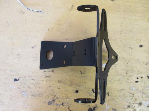
1 FITTING INSTRUCTIONS FOR LP0248BK LICENCE PLATE BRACKET KTM DUKE Page 1 THIS KIT CONTAINS THE ITEMS PICTURED AND LABELLED BELOW. DO NOT PROCEED UNTIL YOU ARE SURE ALL PARTS ARE PRESENT. Please note that the way the kit is packed does not necessarily represent the way of mounting to the bike. THE PARTS SHOWN MAY BE REPRESENTATIVE ONLY (FOR CLARITY OF INSTRUCTIONS ONLY).
2 Page 2 LEGEND ITEM 1 = LICENCE PLATE BRACKET (TB0248) (x1). ITEM 2 = M6 x 15mm LONG BUTTON HEAD BOLTS (x4). ITEM 3 = M6 WASHERS (x4). ITEM 4 = IWC0002 INDICATOR WIRING COVERS (x2). ITEM 5 = REFLECTOR (x1). ITEM 6 = LICENCE PLATE ILLUMINATOR CONNECTOR (CON0014) (x2). ITEM 7 = 150MM LENGTH OF HEATSHRINK (x2). ITEM 8 = 200MM LENGTH OF LARGE HEATSHRINK (x1). ITEM 9 = LICENCE PLATE ILLUMINATOR CONNECTOR (CON0043) (x1). ITEM 10 = I0040 MINI INDICATOR ADAPTOR (x2). ITEM 11 = SMALL CABLE TIES (x3). ITEM 12 = LICENCE PLATE ILLUMINATOR (LA0007) (x1). TOOLS REQUIRED T25, T30 torx driver. 12, 13mm spanner. MAXIMUM TORQUE SETTINGS M5 Bolt = 12 Nm M6 Bolt = 15 Nm


3 Page 3 Picture 1 Picture 2 Picture 3 Picture 4 Picture 5 Picture 6


4 Page 4 Picture 7 Picture 8 Picture 9 Picture 10 Picture 11 Picture 12


5 Page 5 Picture 13 Picture 14 Picture 15 Picture 16 Picture 17 Picture 18


6 Page 6 Picture 19 Picture 20 FITTING INSTRUCTIONS To fit the tail tidy, remove the pillion seat using the motorcycle key as shown in picture 1 and 2. Unplug the connector shown in picture 3. Remove the 4 torx bolts arrowed in picture 4. Gently pull the OEM tail away from the bike removing the wiring sub-harness and rubber plug as shown in pictures 5 and 6. Remove the 3 bolts shown in picture 8. Split the OEM tail in half by gently pull the two sides away from each other as shown in picture 9. Disconnect the OEM tail light and OEM indicators from the sub-harness shown in picture 9 making a note or marking which sub-harness corresponds to the left and right indicators. Remove the rubber plug from the subharness. Fit the tail light (item 12) to the tail bracket (item 1) using the included bolts, washers and nuts as shown in picture 11. Ensure the larger side of the light is facing down so that the number plate is illuminated correctly. If fitting OEM indicators (item 6-CON0014 not required) Remove the OEM indicators from the OEM tail by removing the nut on the threaded boss on the back and threading the indicator and wiring through the hole. Mount the indicators to the corresponding side on the tail bracket (item 1) in the same way they were removed as shown in picture 12. Protect the wiring using an indicator wiring cover (item 4) as shown in picture 15. Pass all three wires through the large heatshrink (item 8) and secure using the small cable ties (item 11) and the cable tie holes as shown in picture 16. Ensure the cable tie heads sit on the wiring side of the tail bracket. Insert the OEM rubber plug into the tail bracket as shown in picture 17. Mount the tail bracket assembly to the bike using the 4 M6 bolts (item 2) and M6 washers (item 3) as shown in picture 18. Pass the wiring through the rubber plug as shown in picture 19. On the inside of the seat connect the tail light connector (item 9-CON0043) to the tail light (item 12) using the bullet connectors. Connect the OEM indicator connectors to their corresponding connectors on the sub-harness removed earlier. Connect the tail light connector (item 9-CON0043) to the OEM sub-harness. Connect the OEM sub-harness to the motorcycle loom with the connector that was removed in picture 3.
7 Test the indicators and tail light for correct function and flash rate. If lights fail to illuminate swap the connectors. Re-fit the pillion seat. Page 7 If fitting mini indicators-not included (Product codes: RG370=Bulb, RG371=LED, RG372=Aero LED) Pass one length of heatshrink (item 7) over the wiring on both mini indicators as shown in picture 13. Place a mini indicator adaptor (item 10) over each indicator ensuring the flat surface sits against the indicator. Pass the mini indicators into the tail bracket (item 1) and secure using the M8 nut included with the indicators as shown in picture 14. Protect the wiring using an indicator wiring cover (item 4) as shown in picture 15. Pass all three wires through the large heatshrink (item 8) and secure using the small cable ties (item 11) and the cable tie holes as shown in picture 16. Ensure the cable tie heads sit on the wiring side of the tail bracket. Insert the OEM rubber plug into the tail bracket as shown in picture 17. Mount the tail bracket assembly to the bike using the 4 M6 bolts (item 2) and M6 washers (item 3) as shown in picture 18. Pass the wiring through the rubber plug as shown in picture 19. On the inside of the seat connect the tail light connector (item 9-CON0043) to the tail light (item 12) using the bullet connectors. On the inside of the seat connect the two indicator connectors (item 6-CON0014) to the mini indicators using the bullet connectors. Connect the indicator connectors to their corresponding left and right connectors on the sub-harness removed earlier. Connect the tail light connector (item 9-CON0043) to the OEM sub-harness. Connect the OEM sub-harness to the motorcycle loom with the connector that was removed in picture 3. Test the indicators and tail light for correct function and flash rate. A resistor (RGR0001/RGR0002-sold separately may be required to achieve the correct flash rate). If lights fail to illuminate swap the connectors. Re-fit the pillion seat. ISSUE 27/04/2018 (HB) Digital copies of these instructions are available to download from CONSUMER NOTICE The catalogue description and any exhibition of samples are only broad indications of the Products and may make design changes which do not diminish their performance or visual appeal and supplying them in such state shall conform to the order. The Buyer acknowledges no representation or warranty (other than as to title) has been given or will apply to the Products other than those in s order or confirmation and the Buyer confirms it has chosen the Products as being of merchantable quality and suitable for its particular purposes. Where fits the Products or undertakes other services it shall exercise reasonable skill and care and rectify any fault free of charge unless the workmanship has been disturbed. The Buyer is responsible for ensuring that the warranty on the motorcycle is not affected by the fitting of the Products. On return of any defective Products shall at its option either supply a replacement or refund the purchase money but shall not be liable if the Products have been modified or used or maintained otherwise than in accordance with s or manufacturer s instructions and good engineering practice or if the defect arises from accident or neglect. Other than identified above and subject to not limiting its liability for causing death and personal injury, it shall not be liable for indirect or consequential loss and otherwise its liability shall be limited to the amounts paid by the Buyer for the Products or the fitting or service concerned. These terms do not affect the Buyer s statutory rights. RETURNS POLICY (NON-FAULTY GOODS) Returns must be pre-authorised (if not pre-authorised the return will be rejected). Goods may only be returned direct to us if they were purchased direct from us (customer must prove if necessary). Otherwise to be returned to original vendor. Goods must be in re-sellable condition, in the opinion of. All returns are subject to a 25% restocking and handling fee (25% of the gross value exc. P&P at the prevailing price at time of purchase). The customer must pay any and all carriage charges. No returns of discontinued products, unless within 14 days of purchase. This policy does not affect your statutory rights and does not refer to faulty goods.
8 NOTICE DE MONTAGE LP0248BK SUPPORT DE PLAQUE KTM DUKE Page 8 Le kit contient les articles exposés ci-dessous, vérifier que toutes les pièces soient présentes avant de procéder au montage. La façon dont le kit est emballé ne correspond pas forcément à la façon de monter les pièces sur la moto. LES PARTIES PRESENTEES PEUVENT ETRE UNIQUEMENT REPRESENTATIVES (POUR LA CLARTE DES INSTRUCTIONS UNIQUEMENT.
9 Page 9 LÉGENDE ARTICLE 1 = SUPPORT DE PLAQUE (TB0248) (x1). ARTICLE 2 = M6 x 15mm BOULONS (x4). ARTICLE 3 = M6 RONDELLES (x4). ARTICLE 4 = IWC0002 CACHES FILS DE CLIGNOTANTS (x2). ARTICLE 5 = REFLECTEUR (x1). ARTICLE 6 = CONNECTEUR DE FEU DE PLAQUE (CON0014) (x2). ARTICLE 7 = 150MM LONGUEUR DE MANCHON THERMO RÉTRACTABLE (x2). ARTICLE 8 = 200MM LONGUEUR DE MANCHON THERMO RÉTRACTABLE (x1). ARTICLE 9 = CONNECTEUR DE FEU DE PLAQUE (CON0043) (x1). ARTICLE 10 = I0040 ADAPTATEUR DE MINI CLIGNOTANT (x2). ARTICLE 11 = PETITS COLLIERS DE SERRAGE (x3). ARTICLE 12 = FEU DE PLAQUE (LA0007) (x1). OUTILS REQUIS Clé Torx T25, T30 Clé à molette 12, 13mm VALEURS DE SERRAGE M5 BOULON = 12Nm M6 BOULON = 15Nm
10 Page 10 NOTICE DE MONTAGE Pour monter le support de plaque, enlever le siège passage à l aide de la clé de la moto, voir photo 1 et 2. Débrancher le connecteur, voir photo 3. Enlever les 4 boulons 4, voir photo 4. Retirer doucement le support d origine de la moto, en enlevant le sous harnais de fils et la prise en caoutchouc, voir photos 5 and 6. Enlever les 3 boulons, voir photo 8. Scinder le support d origine en 2 moitiés en tirant doucement les 2 côtés dans un sens opposé, voir photo 9. Déconnecter le feu de plaque d origine et les clignotants d origine du sous harnais, voir photo 9 en prenant note ou en marquant la correspondance du sou-harnais avec les clignotants du côté gauche ou du côté droit. Enlever la prise en caoutchouc du sous-harnais. Monter le feu de plaque (article 12) sur le support de plaque (article 1) en utilisant les boulons fournis, les rondelles et écrous, voir photo 11. Veiller à ce que le côté le plus large du feu soit orienté vers le bas de façon à ce que le numéro de plaque d immatriculation soit correctement éclairé. Si vous montez les clignotants d origine (article 6-CON0014 non requis) Enlever les clignotants d origine du support d origine en enlevant l écrou sur le patron fileté au bas et en passant le clignotant et le fil dans le trou. Monter les clignotants du côté correspondant sur le support de plaque (article 1) de la même façon qu ils ont été enlevés, voir photo 12. Protéger le fil en utilisant un cache fil de clignotant (article 4), voir photo 15. Passer les 3 fils dans le manchon thermos rétractable fourni (article 8) puis fixer à l aide de petits colliers de serrage fournis (article 11) et des trous qui leur sont réservés, voir photo 16. Veiller à ce que les têtes de collier de serrage se placent du côté du fil sur le support de plaque. Insérer la prise en caoutchouc d origine dans le support de plaque, voir photo 17. Monter l ensemble du support de plaque sur la moto en utilisant les 4 boulons M6 (article 2) et rondelles M6 (article 3), voir photo 18. Passer le fil dans la prise en caoutchouc, voir photo 19. A l intérieur du siège, connecter le connecteur de feu de plaque (article 9-CON0043) sur le feu de plaque (article 12) en utilisant les connecteurs. Connecter les connecteurs de clignotant d origine aux connecteurs correspondant sur le sous harnais enlevé un peu plus tôt. Connecter le connecteur de feu de plaque (article 9-CON0043) sur le sous harnais d origine. Connecter le sous harnais d origine sur le faisceau de la moto avec le connecteur qui a été enlevé sur la photo 3. Tester les clignotants et le feu de plaque pour vérifier leur bon fonctionnement et leur niveau d éclairage Si l éclairage échoue, tournez les connecteurs. Remonter le siege passager. Si vous montez les mini clignotants non inclus (codes produit : RG370=Ampoule, RG371=LED, RG372=LED latérale) Passer une longueur de manchon thermo rétractable (article 7) sur le fil sur les 2 mini clignotants, voir photo 13. Placer un adaptateur de mini clignotant (article 10) sur chaque clignotant en veillant à ce que la surface plate se place contre le clignotant. Passer les mini clignotants dans le support de plaque (article 1) puis fixer à l aide d un écrou M8 fourni avec les clignotants, voir photo 14. Protéger le fil à l aide du cache fil de clignotant (article 4), voir photo 15.
11 Page 11 Passer les 3 fils dans le manchon thermos rétractable (article 8) puis fixer à l aide des colliers de serrage fournis (article 11) et des trous qui leur sont réservés, voir photo 16. Veiller à ce que les têtes de collier de serrage se placent du côté du fil sur le support de plaque. Insérer la prise en caoutchouc d origine dans le support de plaque, voir photo 17. Monter l ensemble du support de plaque sur la moto en utilisant les 4 boulons M6 (article 2) et rondelles M6 (article 3), voir photo 18. Passer le fil dans la prise en caoutchouc, voir photo 19. A l intérieur du siège, connecter le connecteur de feu de plaque (article 9-CON0043) sur le feu de plaque (article 12) en utilisant les connecteurs. A l intérieur du siège, connecter les 2 connecteurs de clignotant (article 6-CON0014) sur les mini clignotants en utilisant les connecteurs. Connecter les connecteurs de clignotant à leurs connecteurs correspondant du côté gauche ou du côté droit sur le sous-harnais enlevé un peu plus tôt. Connecter le connecteur de feu de plaque (article 9-CON0043) sur le sous harnais d origine. Connecter le sous harnais d origine sur le faisceau de la moto avec le connecteur qui a été enlevé sur la photo 3. Tester les clignotants et le feu de plaque pour vérifier leur bon fonctionnement et leur niveau d éclairage. Une résistance (RGR0001/RGR0002- vendue séparément, peut être nécessaire pour obtenir un niveau d éclairage correct). Si l éclairage échoue, tournez les connecteurs. Remonter le siege passager. ISSUE 27/04/2018 (HB) Notice disponible au téléchargement sur CONSUMER NOTICE The catalogue description and any exhibition of samples are only broad indications of the Products and may make design changes which do not diminish their performance or visual appeal and supplying them in such state shall conform to the order. The Buyer acknowledges no representation or warranty (other than as to title) has been given or will apply to the Products other than those in s order or confirmation and the Buyer confirms it has chosen the Products as being of merchantable quality and suitable for its particular purposes. Where fits the Products or undertakes other services it shall exercise reasonable skill and care and rectify any fault free of charge unless the workmanship has been disturbed. The Buyer is responsible for ensuring that the warranty on the motorcycle is not affected by the fitting of the Products. On return of any defective Products shall at its option either supply a replacement or refund the purchase money but shall not be liable if the Products have been modified or used or maintained otherwise than in accordance with s or manufacturer s instructions and good engineering practice or if the defect arises from accident or neglect. Other than identified above and subject to not limiting its liability for causing death and personal injury, it shall not be liable for indirect or consequential loss and otherwise its liability shall be limited to the amounts paid by the Buyer for the Products or the fitting or service concerned. These terms do not affect the Buyer s statutory rights. RETURNS POLICY (NON-FAULTY GOODS) Returns must be pre-authorised (if not pre-authorised the return will be rejected). Goods may only be returned direct to us if they were purchased direct from us (customer must prove if necessary). Otherwise to be returned to original vendor. Goods must be in re-sellable condition, in the opinion of. All returns are subject to a 25% restocking and handling fee (25% of the gross value exc. P&P at the prevailing price at time of purchase). The customer must pay any and all carriage charges. No returns of discontinued products, unless within 14 days of purchase. This policy does not affect your statutory rights and does not refer to faulty goods.
12 MONTAGEANLEITUNG FÜR LP0248BK KENNZEICHENHALTER KTM DUKE Page 12 ALLE GELIEFERTEN TEILE SIND UNTEN ABGEBILDET UND GEKENNZEICHNET. BEVOR SIE MIT DER MONTAGE BEGINNEN, ÜBERPRÜFEN SIE SORGFÄLTIG, DASS ALLE TEILE VORHANDEN SIND. Die Verpackung der Teile stellt nicht die Reihenfolge der Montage dar. DIE UNTEN ABGEBILDETEN TEILE DIENEN LEDIGLICH ZUR ERKLÄRUNG
13 Page 13 LIEFERUMFANG ARTIKEL 1 = KENNZEICHENHALTER (TB0248) (x1) ARTIKEL 2 = M6 x 15mm INBUSSCHRAUBEN (x4) ARTIKEL 3 = M6 UNTERLEGSCHEIBE (x4) ARTIKEL 4 = IWC0002 ABDECKUNGEN FÜR BLINKERKABEL (x2) ARTIKEL 5 = RÜCKSTRAHLER (x1) ARTIKEL 6 = VERBINDUNG FÜR KENNZEICHENBELEUCHTUNG (CON0014) (x2) ARTIKEL 7 = 150MM SCHRUMPFSCHLAUCH (x2) ARTIKEL 8 = 200MM GR. SCHRUMPFSCHLAUCH (x1) ARTIKEL 9 = VERBINDUNG FÜR KENNZEICHENBELEUCHTUNG (CON0043) (x1) ARTIKEL 10 = I0040 MINIBLINKER-ADAPTER (x2) ARTIKEL 11 = KLEINE KABELBINDER (x3) ARTIKEL 12 = KENNZEICHENBELEUCHTUNG (LA0007) (x1) SIE BENÖTIGEN FOLGENDES WERKZEUG T25, T30 Torx-Schlüssel 12 and 13mm Schraubenschlüssel
14 MAX. ANZUGSDREHMOMENT: M5 SCHRAUBE = 12NM M6 SCHRAUBE = 15NM Page 14 MONTAGEANLEITUNG Um den Kennzeichenhalter montieren zu können, entfernen Sie zuerst den Beifahrersitz. Verwenden Sie hierfür den Schlüssel siehe Abbildungen 1 und 2. Trennen Sie den Steckverbinder, der in Abbildung 3 abgebildet ist. Entfernen Sie die 4 Torx-Schrauben, die in Abbildung 4 mit Pfeilen gekennzeichnet sind. Den original Kennzeichenhalter vorsichtig vom Motorrad wegziehen hierbei den Kabelstrang sowie den Gummistopfen entfernen siehe Abbildungen 5 und 6. Entfernen Sie die 3 Schrauben, die in Abbildung 8 abgebildet sind. Den original Kennzeichenhalter in zwei Hälften teilen, indem Sie die zwei Seiten auseinander ziehen siehe Abbildung 9. Trennen Sie die original Kennzeichenbeleuchtung und die original Blinker vom Kabelstrang, wie in Abbildung 9 abgebildet bitte notieren / markieren Sie den jeweiligen Kabelstrang für den rechten bzw. linken Blinker. Entfernen Sie den Gummistopfen vom Kabelstrang. Montieren Sie die Kennzeichenbeleuchtung (Artikel 12) am Kennzeichenhalter (Artikel 1) benutzen Sie hierfür die Schrauben, Unterlegscheiben und Muttern vom Kit siehe Abbildung 11. Bitte darauf achten, dass die große Seite des Lichts nach unten gerichtet ist, um das Kennzeichen somit ordnungsgemäß zu beleuchten. Wenn Sie die original Blinker verwenden (Artikel 6-CON0014 wird nicht benötigt) Entfernen Sie die original Blinker vom original Kennzeichenhalter, indem Sie die Mutter hinten am Gewindeeinsatz entfernen und den Blinker mit dem Kabel durch die Öffnung führen. Montieren Sie die Blinker an den entsprechenden Seiten des Kennzeichenhalters (Artikel 1) auf der gleichen Art wie bei der Entfernung siehe Abbildung 12. Die Abdeckung für die Kabel (Artikel 4) wie in Abbildung 15 anbringen, um die Kabel zu schützen. Führen Sie die alle drei Kabel durch den großen Schrumpfschlauch (Artikel 8) und diese mit den kleinen Kabelbindern (Artikel 11) an den Öffnungen für die Kabelbinder befestigen siehe Abbildung 16. Bitte darauf achten, dass die Verschlussteile der Kabelbinder an der Seite mit den Kabeln positioniert sind. Den Gummistopfen am Kennzeichenhalter montieren siehe Abbildung 17. Montieren Sie die Kennzeichenhalter-Einheit am Motorrad mit den vier M6 Schrauben (Artikel 2) und M6 Unterlegscheiben (Artikel 3) wie in Abbildung 18 abgebildet. Führen Sie die Kabel durch den Gummistopfen siehe Abbildung 19. An der Innenseite des Sitzes die Verbindung für die Kennzeichenbeleuchtung (Artikel 9-CON0043) mit der RG Kennzeichenbeleuchtung (Artikel 12) verbinden mittels Kabelverbindung. Verbinden Sie die original Verbinder für die Blinker mit den entsprechenden Verbindungen am zuvor entfernten Kabelstrang. Verbinden Sie die Verbindung für die Kennzeichenbeleuchtung (Artikel 9-CON0043) mit dem original Kabelstrang. Verbinden Sie den original Kabelstrang mit dem Kabelbaum am Motorrad benutzen Sie hierbei den Verbinder, der in Abbildung 3 entfernt wurde. Überprüfen Sie, dass die Blinker und die Kennzeichenbeleuchtung ordnungsgemäß funktionieren, und dass die Blinker die richtige Blitzgeschwindigkeit haben. Falls die Beleuchtung nicht funktionieren sollte, tauschen Sie die Kabelverbinder untereinander. Montieren Sie den Beifahrersitz wieder.
15 Page 15 Wenn Sie Miniblinker verwenden nicht im Lieferumfang enthalten (Artikel-Nr.: RG370=Glühbirne, RG371=LED, RG372=Aero LED) Eine Länge Schrumpfschlauch (Artikel 7) an der Verkabelung der zwei Miniblinker anbringen siehe Abbildung 13. Je einen Miniblinker-Adapter (Artikel 10) an den Blinkern anbringen bitte darauf achten, dass die flache Fläche am Blinker anliegt. Die Miniblinker am Kennzeichenhalter (Artikel 1) anbringen und mit der M8 Mutter (im Lieferumfang der Miniblinker) befestigen siehe Abbildung 14. Die Abdeckung für die Kabel (Artikel 4) wie in Abbildung 15 anbringen, um die Kabel zu schützen. Führen Sie die alle drei Kabel durch den großen Schrumpfschlauch (Artikel 8) und diese mit den kleinen Kabelbindern (Artikel 11) an den Öffnungen für die Kabelbinder befestigen siehe Abbildung 16. Bitte darauf achten, dass die Verschlussteile der Kabelbinder an der Seite mit den Kabeln positioniert sind. Den Gummistopfen am Kennzeichenhalter montieren siehe Abbildung 17. Montieren Sie die Kennzeichenhalter-Einheit am Motorrad mit den vier M6 Schrauben (Artikel 2) und M6 Unterlegscheiben (Artikel 3) wie in Abbildung 18 abgebildet. Führen Sie die Kabel durch den Gummistopfen siehe Abbildung 19. An der Innenseite des Sitzes die Verbindung für die Kennzeichenbeleuchtung (Artikel 9-CON0043) mit der RG Kennzeichenbeleuchtung (Artikel 12) verbinden (mittels Kabelverbindung). An der Innenseite des Sitzes die zwei Verbindungen für die Blinker (Artikel 6-CON0014) mit den Miniblinker verbinden (mittels Kabelverbindungen). Verbinden Sie die Verbindungen für die Blinker mit der entsprechenden rechts oder links Verbindung am zuvor entfernten Kabelstrang. Verbinden Sie die Verbindung für die Kennzeichenbeleuchtung (Artikel 9-CON0043) mit dem original Kabelstrang. Verbinden Sie den original Kabelstrang mit dem Kabelbaum am Motorrad benutzen Sie hierbei den Verbinder, der in Abbildung 3 entfernt wurde. Überprüfen Sie, dass die Blinker und die Kennzeichenbeleuchtung ordnungsgemäß funktionieren, und dass sie Blinker die richtige Blitzgeschwindigkeit haben eventuell benötigen Sie einen Widerstand (RGR0001/RGR0002-separat erhältlich). Falls die Beleuchtung nicht funktionieren sollte, tauschen Sie die Kabelverbinder untereinander. Montieren Sie den Beifahrersitz wieder. AUSGABE 27/04/2018 (HB) Eine digitale Version dieser Montageanleitung kann auf folgender Seite heruntergeladen werden:
16 Page 16 CONSUMER NOTICE The catalogue description and any exhibition of samples are only broad indications of the Products and may make design changes which do not diminish their performance or visual appeal and supplying them in such state shall conform to the order. The Buyer acknowledges no representation or warranty (other than as to title) has been given or will apply to the Products other than those in s order or confirmation and the Buyer confirms it has chosen the Products as being of merchantable quality and suitable for its particular purposes. Where fits the Products or undertakes other services it shall exercise reasonable skill and care and rectify any fault free of charge unless the workmanship has been disturbed. The Buyer is responsible for ensuring that the warranty on the motorcycle is not affected by the fitting of the Products. On return of any defective Products shall at its option either supply a replacement or refund the purchase money but shall not be liable if the Products have been modified or used or maintained otherwise than in accordance with s or manufacturer s instructions and good engineering practice or if the defect arises from accident or neglect. Other than identified above and subject to not limiting its liability for causing death and personal injury, it shall not be liable for indirect or consequential loss and otherwise its liability shall be limited to the amounts paid by the Buyer for the Products or the fitting or service concerned. These terms do not affect the Buyer s statutory rights. RETURNS POLICY (NON-FAULTY GOODS) Returns must be pre-authorised (if not pre-authorised the return will be rejected). Goods may only be returned direct to us if they were purchased direct from us (customer must prove if necessary). Otherwise to be returned to original vendor. Goods must be in re-sellable condition, in the opinion of. All returns are subject to a 25% restocking and handling fee (25% of the gross value exc. P&P at the prevailing price at time of purchase). The customer must pay any and all carriage charges. No returns of discontinued products, unless within 14 days of purchase. This policy does not affect your statutory rights and does not refer to faulty goods.
Fitting Instructions for DG0017 BK Downpipe Grille BMW F800GT 2013
 Fitting Instructions for DG0017 BK Downpipe Grille BMW F800GT 2013 In This Kit There Should Be 1 x Downpipe Grille (DG0017) 2 x M5 Nyloc nuts PICTURE 1 PICTURE 2 PICTURE 3 PICTURE 4 1 PICTURE 5 PICTURE
Fitting Instructions for RAD0129BK Radiator Guard MV AGUSTA F3 2012
 Fitting Instructions for RAD0129BK Radiator Guard MV AGUSTA F3 2012 In This Kit There Should Be 1x Radiator Guard (RAD0129BK) 2x 100mm Lengths of self-adhesive Foam 1x Cable Tie Picture 1 Picture 2 Picture
Fitting Instructions for RAD0185BK Radiator Guard TRIUMPH STREET TRIPLE RX 2015
 Fitting Instructions for RAD0185BK Radiator Guard TRIUMPH STREET TRIPLE RX 2015 In This Kit There Should Be 1x Radiator Guard (RAD0185BK) 4x 100mm Lengths of self-adhesive Foam Picture 1 Picture 2 Picture
Fitting Instructions for SRG0013 Radiator Guard KAWASAKI ER6-N / ER6-F / 650 Versys 10-
 Fitting Instructions for SRG0013 Radiator Guard KAWASAKI ER6-N 09-11 / ER6-F 09-11 / 650 Versys 10- PICTURE 1 PICTURE 2 In This Kit There Should Be 1x Radiator Guard 1x M6x20mm long button head bolt 1x
Fitting Instructions for RAD0151BK Radiator Guard BMW R1200GS 2013
 Fitting Instructions for RAD0151BK Radiator Guard BMW R1200GS 2013 In This Kit There Should Be 2x Radiator Guard (RAD0151BK Left & Right) 2x 100mm Lengths of self-adhesive Foam Picture 1 Picture 2 Picture
FITTING INSTRUCTIONS FOR LP0245BK LICENCE PLATE BRACKET KAWASAKI NINJA (FOR USE WITH STANDARD AND R&G MINI INDICATORS (8mm))
)") FITTING INSTRUCTIONS FOR LP0245BK LICENCE PLATE BRACKET KAWASAKI NINJA 400 2018 (FOR USE WITH STANDARD AND R&G MINI INDICATORS (8mm)) Page 1 THIS KIT CONTAINS THE ITEMS PICTURED AND LABELLED BELOW. DO
FITTING INSTRUCTIONS FOR LP0245BK LICENCE PLATE BRACKET KAWASAKI NINJA 400 2018 (FOR USE WITH STANDARD AND R&G MINI INDICATORS (8mm)) Page 1 THIS KIT CONTAINS THE ITEMS PICTURED AND LABELLED BELOW. DO
Fitting Instructions for DG0012 BK Downpipe Grille KAWASAKI NINJA
 Fitting Instructions for DG0012 BK Downpipe Grille KAWASAKI NINJA 300 2013-- In This Kit There Should Be 1x Downpipe Grille (DG0012) 2x M6 x 30mm Button Head Bolts 2 3 4 1 5 6 Picture 1 Picture 2 1 Picture
Fitting Instructions for DG0011 BK Downpipe Grille TRIUMPH TROPHY 2012
 Fitting Instructions for DG0011 BK Downpipe Grille TRIUMPH TROPHY 2012 In This Kit There Should Be 1x Downpipe Grille (DG0011) Picture 1 Picture 2 1 FITTING INSTRUCTIONS Picture 3 Picture 4 TOOLS REQUIRED
FITTING INSTRUCTIONS FOR SBP0005 SPINDLE BLANKING PLATES DUCATI DIAVEL, MONSTER & PANIGALE MULTISTRADA 1200
 FITTING INSTRUCTIONS FOR SBP0005 SPINDLE BLANKING PLATES DUCATI DIAVEL, MONSTER1200 14- & PANIGALE 1199 2011- MULTISTRADA 1200 THIS KIT CONTAINS THE ITEMS PICTURED AND LABELLED BELOW. DO NOT PROCEED UNTIL
FITTING INSTRUCTIONS FOR LP0068BK & LP0070BK LICENCE PLATE BRACKET KTM RC8 2008
 FITTING INSTRUCTIONS FOR LP0068BK & LP0070BK LICENCE PLATE BRACKET Please note that the way the kit is packed does not necessarily represent the way of mounting to the bike Please note that in cases where
FITTING INSTRUCTIONS FOR LP0104BK LICENCE PLATE BRACKET HONDA CBR 250R 2011/ WK SP250 / 125 / 50
 FITTING INSTRUCTIONS FOR LP0104BK LICENCE PLATE BRACKET HONDA CBR 250R 2011/ WK SP250 / 125 / 50 Page 1 THIS KIT CONTAINS THE ITEMS PICTURED AND LABELLED BELOW. DO NOT PROCEED UNTIL YOU ARE SURE ALL PARTS
FITTING INSTRUCTIONS FOR CP0443 CRASH PROTECTORS DUCATI MULTISTRADA 1260, 1260S 2018-
 FITTING INSTRUCTIONS FOR CP0443 CRASH PROTECTORS DUCATI MULTISTRADA 1260, 1260S 2018- Page 1 PICTURE A PICTURE B THIS KIT CONTAINS THE ITEMS PICTURED AND LABELLED BELOW. DO NOT PROCEED UNTIL YOU ARE SURE
FITTING INSTRUCTIONS FOR AB0013BK ADVENTURE BARS APRILIA CAPONORD
 FITTING INSTRUCTIONS FOR AB001BK ADVENTURE BARS APRILIA CAPONORD 1200 201-1 PICTURE A PICTURE B THIS KIT CONTAINS THE ITEMS PICTURED AND LABELLED BELOW. DO NOT PROCEED UNTIL YOU ARE SURE ALL PARTS ARE
Fitting Instructions for RAD0172BK Radiator Guard DUCATI MONSTER 1200 14-
 Fitting Instructions for RAD0172BK Radiator Guard DUCATI MONSTER 1200 14- In This Kit There Should Be 1x Radiator Guard (RAD0172BK) 2x 100mm Lengths of self-adhesive Foam Picture 1 Picture 2 Picture 3
FITTING INSTRUCTIONS FOR CP0365BL CRASH PROTECTORS YAMAHA MT PICTURE C
 FITTING INSTRUCTIONS FOR CP0365BL CRASH PROTECTORS YAMAHA MT 07 2014- Page 1 PICTURE A PICTURE B REAR OF BIKE FRONT OF BIKE PICTURE C THIS KIT CONTAINS THE ITEMS PICTURED AND LABELLED BELOW. DO NOT PROCEED
FITTING INSTRUCTIONS FOR LP0247BK LICENCE PLATE BRACKET KAWASAKI H2 SX 2018 (FOR USE WITH STANDARD AND R&G MINI INDICATORS (8mm))
)") FITTING INSTRUCTIONS FOR LP0247BK LICENCE PLATE BRACKET KAWASAKI H2 SX 2018 (FOR USE WITH STANDARD AND R&G MINI INDICATORS (8mm)) Page 1 THIS KIT CONTAINS THE ITEMS PICTURED AND LABELLED BELOW. DO NOT
FITTING INSTRUCTIONS FOR LP0247BK LICENCE PLATE BRACKET KAWASAKI H2 SX 2018 (FOR USE WITH STANDARD AND R&G MINI INDICATORS (8mm)) Page 1 THIS KIT CONTAINS THE ITEMS PICTURED AND LABELLED BELOW. DO NOT
FITTING INSTRUCTIONS FOR CP0273 FRONT MOUNTING CRASH PROTECTORS TRIUMPH SPEED TRIPLE 2011 PICTURE 1 PICTURE 2
 FITTING INSTRUCTIONS FOR CP0273 FRONT MOUNTING CRASH PROTECTORS TRIUMPH SPEED TRIPLE 2011 PICTURE 1 PICTURE 2 THIS KIT CONTAINS THE ITEMS PICTURED AND LISTED BELOW. DO NOT PROCEED UNTIL YOU ARE SURE ALL
FITTING INSTRUCTIONS FOR LP0158 LICENCE PLATE BRACKET KTM 1290 SUPER DUKE R 2014
 FITTING INSTRUCTIONS FOR LP0158 LICENCE PLATE BRACKET KTM 1290 SUPER DUKE R 2014 Page 1 THIS KIT CONTAINS THE ITEMS PICTURED AND LABELLED BELOW. DO NOT PROCEED UNTIL YOU ARE SURE ALL PARTS ARE PRESENT.
FITTING INSTRUCTIONS FOR LP0122BK LICENCE PLATE BRACKET KTM 690 DUKE
 FITTING INSTRUCTIONS FOR LP0122BK LICENCE PLATE BRACKET KTM 690 DUKE 1111 2012- Page 1 THIS KIT CONTAINS THE ITEMS PICTURED AND LABELLED BELOW. DO NOT PROCEED UNTIL YOU ARE SURE ALL PARTS ARE PRESENT.
FITTING INSTRUCTIONS FOR LP0135BK LICENCE PLATE BRACKET KAWASAKI Z (FOR USE WITH STANDARD AND MINI INDICATORS (8mm))
)") FITTING INSTRUCTIONS FOR LP0135BK LICENCE PLATE BRACKET KAWASAKI Z800 2013 (FOR USE WITH STANDARD AND MINI INDICATORS (8mm)) Page 1 EMS PICTURED AND LABELLED BELOW. DO NOT PROCEED UNTIL YOU ARE SURE ALL
FITTING INSTRUCTIONS FOR LP0135BK LICENCE PLATE BRACKET KAWASAKI Z800 2013 (FOR USE WITH STANDARD AND MINI INDICATORS (8mm)) Page 1 EMS PICTURED AND LABELLED BELOW. DO NOT PROCEED UNTIL YOU ARE SURE ALL
FITTING INSTRUCTIONS FOR CP0247BL AERO CRASH PROTECTORS KAWASAKI ER-6N 09 -
 FITTING INSTRUCTIONS FOR CP0247BL AERO CRASH PROTECTORS Please note that the way the kit is packed does not necessarily represent the way of mounting to the bike Please note that in cases where kits are
FITTING INSTRUCTIONS FOR CP0248BL AERO CRASH PROTECTORS TRIUMPH TIGER
 FITTING INSTRUCTIONS FOR CP0248BL AERO CRASH PROTECTORS A B TOWARDS REAR FRONT OF BIKE TOWARDS OF BIKE Please note that the way the kit is packed does not necessarily represent the way of mounting to the
FITTING INSTRUCTIONS FOR LP0097 LICENCE PLATE BRACKET DUCATI MONSTER DUCATI MONSTER DUCATI MONSTER
 FITTING INSTRUCTIONS FOR LP0097 LICENCE PLATE BRACKET DUCATI MONSTER 796 2010- DUCATI MONSTER 696 2008- DUCATI MONSTER 1100 2009- THIS KIT CONTAINS THE ITEMS PICTURED AND LABELLED BELOW. DO NOT PROCEED
FITTING INSTRUCTIONS FOR LP0127BK LICENCE PLATE BRACKET YAMAHA T-MAX
 FITTING INSTRUCTIONS FOR LP0127BK LICENCE PLATE BRACKET YAMAHA T-MAX 530 2012 THIS KIT CONTAINS THE ITEMS PICTURED AND LABELLED BELOW. DO NOT PROCEED UNTIL YOU ARE SURE ALL PARTS ARE PRESENT. Please note
FITTING INSTRUCTIONS FOR LP0120 LICENCE PLATE BRACKET HUSQVARNA NUDA 900R 2012
 FITTING INSTRUCTIONS FOR LP0120 LICENCE PLATE BRACKET HUSQVARNA NUDA 900R 2012 Page 1 THIS KIT CONTAINS THE ITEMS PICTURED AND LABELLED BELOW. DO NOT PROCEED UNTIL YOU ARE SURE ALL PARTS ARE PRESENT. Please
FITTING INSTRUCTIONS FOR LP0241BK LICENCE PLATE BRACKET YAMAHA MT (FOR USE WITH STANDARD AND R&G MINI INDICATORS (8mm))
)") FITTING INSTRUCTIONS FOR LP0241BK LICENCE PLATE BRACKET YAMAHA MT-09 2017 (FOR USE WITH STANDARD AND R&G MINI INDICATORS (8mm)) Page 1 THIS KIT CONTAINS THE ITEMS PICTURED AND LABELLED BELOW. DO NOT PROCEED
FITTING INSTRUCTIONS FOR LP0241BK LICENCE PLATE BRACKET YAMAHA MT-09 2017 (FOR USE WITH STANDARD AND R&G MINI INDICATORS (8mm)) Page 1 THIS KIT CONTAINS THE ITEMS PICTURED AND LABELLED BELOW. DO NOT PROCEED
BRUUDT Kennzeichenhalter für die Honda NC750X ab 2016 BRUUDT Tail Tidy for the Honda NC750X 2016 and onwards.
 Montageanleitung Mounting instructions BRUUDT Kennzeichenhalter für die Honda NC750X ab 2016 BRUUDT Tail Tidy for the Honda NC750X 2016 and onwards. Noch einmal vielen Dank, dass Sie sich für unsere Produkte
FITTING INSTRUCTIONS FOR LP0159BK LICENCE PLATE BRACKET YAMAHA MT
 FITTING INSTRUCTIONS FOR LP0159BK LICENCE PLATE BRACKET YAMAHA MT-07 14- THIS KIT CONTAINS THE ITEMS PICTURED AND LABELLED BELOW. DO NOT PROCEED UNTIL YOU ARE SURE ALL PARTS ARE PRESENT. Please note that
FITTING INSTRUCTIONS FOR LP0113BK LICENCE PLATE BRACKET HONDA FIREBLADE CBR1000RR
 FITTING INSTRUCTIONS FOR LP0113BK LICENCE PLATE BRACKET HONDA FIREBLADE CBR1000RR 2012-2013 Page 1 THIS KIT CONTAINS THE ITEMS PICTURED AND LABELLED BELOW. DO NOT PROCEED UNTIL YOU ARE SURE ALL PARTS ARE
FITTING INSTRUCTIONS FOR LP0157BK LICENCE PLATE BRACKET MV AGUSTA RIVALE
 FITTING INSTRUCTIONS FOR LP0157BK LICENCE PLATE BRACKET MV AGUSTA RIVALE 800 14- THIS KIT CONTAINS THE ITEMS PICTURED AND LABELLED BELOW. DO NOT PROCEED UNTIL YOU ARE SURE ALL PARTS ARE PRESENT. Please
FITTING INSTRUCTIONS FOR CP0267BL CRASH PROTECTORS SUZUKI GSX 1250FA 2010
 FITTING INSTRUCTIONS FOR CP0267BL CRASH PROTECTORS SUZUKI GSX 1250FA 2010 THIS KIT CONTAINS THE ITEMS PICTURED AND LISTED BELOW. DO NOT PROCEED UNTIL YOU ARE SURE ALL PARTS ARE PRESENT. Please note that
FITTING INSTRUCTIONS FOR CP0249BL AERO CRASH PROTECTORS KAWASAKI ER-6F 09 -
 FITTING INSTRUCTIONS FOR CP0249BL AERO CRASH PROTECTORS Please note that the way the kit is packed does not necessarily represent the way of mounting to the bike Please note that in cases where kits are
FITTING INSTRUCTIONS FOR LP0117 LICENCE PLATE BRACKET KAWASAKI VERSYS
 FITTING INSTRUCTIONS FOR LP0117 LICENCE PLATE BRACKET KAWASAKI VERSYS 1000 2012 Page 1 THIS KIT CONTAINS THE ITEMS PICTURED AND LABELLED BELOW. DO NOT PROCEED UNTIL YOU ARE SURE ALL PARTS ARE PRESENT.
FITTING INSTRUCTIONS FOR LP0254BK LICENCE PLATE BRACKET HONDA CB1000R 18-
 FITTING INSTRUCTIONS FOR LP0254BK LICENCE PLATE BRACKET HONDA CB1000R 18- Page 1 THIS KIT CONTAINS THE ITEMS PICTURED AND LABELLED BELOW. DO NOT PROCEED UNTIL YOU ARE SURE ALL PARTS ARE PRESENT. Please
BRUUDT Kennzeichenhalter für die Yamaha MT-03 und R3 BRUUDT Tail Tidy for the Yamaha MT-03 and R3
 Montageanleitung Mounting instructions BRUUDT Kennzeichenhalter für die Yamaha MT-03 und R3 BRUUDT Tail Tidy for the Yamaha MT-03 and R3 Noch einmal vielen Dank, dass Sie sich für unsere Produkte entschieden
FITTING INSTRUCTIONS FOR LP0109BK LICENCE PLATE BRACKET SUZUKI BANDIT
 FITTING INSTRUCTIONS FOR LP0109BK LICENCE PLATE BRACKET SUZUKI BANDIT 650 2010 THIS KIT CONTAINS THE ITEMS PICTURED AND LABELLED BELOW. DO NOT PROCEED UNTIL YOU ARE SURE ALL PARTS ARE PRESENT. Please note
BRUUDT Kennzeichenhalter für die Yamaha MT-07 BRUUDT Tail Tidy for the Yamaha MT-07
 Montageanleitung Mounting instructions BRUUDT Kennzeichenhalter für die Yamaha MT-07 BRUUDT Tail Tidy for the Yamaha MT-07 Noch einmal vielen Dank, dass Sie sich für unsere Produkte entschieden haben!
FITTING INSTRUCTIONS FOR CP0286 CRASH PROTECTORS DUCATI DIAVEL & DIAVEL STRADA 13-
 FITTING INSTRUCTIONS FOR CP028 CRASH PROTECTORS DUCATI DIAVEL 2011- & DIAVEL STRADA 1- PICTURE A PICTURE B REAR OF BIKE PICTURE C FRONT OF BIKE THIS KIT CONTAINS THE ITEMS PICTURED AND LABELLED BELOW.
FITTING INSTRUCTIONS FOR LP0141BK LICENCE PLATE BRACKET HONDA CBR500R/ CB500X and CB500F 2013
 FITTING INSTRUCTIONS FOR LP0141BK LICENCE PLATE BRACKET HONDA CBR500R/ CB500X and CB500F 2013 Page 1 THIS KIT CONTAINS THE ITEMS PICTURED AND LABELLED BELOW. DO NOT PROCEED UNTIL YOU ARE SURE ALL PARTS
BRUUDT Kennzeichenhalter für die Kawasaki Z800 BRUUDT Tail Tidy fort the Kawasaki Z800
 Montageanleitung Mounting instructions BRUUDT Kennzeichenhalter für die Kawasaki Z800 BRUUDT Tail Tidy fort the Kawasaki Z800 Noch einmal vielen Dank, dass Sie sich für unsere Produkte entschieden haben!
FITTING INSTRUCTIONS FOR LP0096 LICENCE PLATE BRACKET DUCATI MULTISTRADA (NOT COMPATIBLE WITH SIDE LUGGAGE)
") FITTING INSTRUCTIONS FOR LP0096 LICENCE PLATE BRACKET DUCATI MULTISTRADA 1200 2010 (NOT COMPATIBLE WITH SIDE LUGGAGE) THIS KIT CONTAINS THE ITEMS PICTURED AND LABELLED BELOW. DO NOT PROCEED UNTIL YOU ARE
FITTING INSTRUCTIONS FOR LP0096 LICENCE PLATE BRACKET DUCATI MULTISTRADA 1200 2010 (NOT COMPATIBLE WITH SIDE LUGGAGE) THIS KIT CONTAINS THE ITEMS PICTURED AND LABELLED BELOW. DO NOT PROCEED UNTIL YOU ARE
FITTING INSTRUCTIONS FOR LP0114BK LICENCE PLATE BRACKET HONDA NC700X 2012
 FITTING INSTRUCTIONS FOR LP0114BK LICENCE PLATE BRACKET HONDA NC700X 2012 Page 1 THIS KIT CONTAINS THE ITEMS PICTURED AND LABELLED BELOW. DO NOT PROCEED UNTIL YOU ARE SURE ALL PARTS ARE PRESENT. Please
FITTING INSTRUCTIONS FOR LP0116 LICENCE PLATE BRACKET DUCATI STREETFIGHTER
 FITTING INSTRUCTIONS FOR LP0116 LICENCE PLATE BRACKET DUCATI STREETFIGHTER 848 2012 Page 1 THIS KIT CONTAINS THE ITEMS PICTURED AND LABELLED BELOW. DO NOT PROCEED UNTIL YOU ARE SURE ALL PARTS ARE PRESENT.
FITTING INSTRUCTIONS FOR LP0126BK LICENCE PLATE BRACKET MV AGUSTA F3 2012
 FITTING INSTRUCTIONS FOR LP0126BK LICENCE PLATE BRACKET MV AGUSTA F3 2012 THIS KIT CONTAINS THE ITEMS PICTURED AND LABELLED BELOW. DO NOT PROCEED UNTIL YOU ARE SURE ALL PARTS ARE PRESENT. Please note that
FITTING INSTRUCTIONS FOR LP0093BK LICENCE PLATE BRACKET HONDA CBR1000 RR 2010
 FITTING INSTRUCTIONS FOR LP0093BK LICENCE PLATE BRACKET HONDA CBR1000 RR 2010 THIS KIT CONTAINS THE ITEMS PICTURED AND LABELLED BELOW. DO NOT PROCEED UNTIL YOU ARE SURE ALL PARTS ARE PRESENT. Please note
FITTING INSTRUCTIONS FOR LP0092BK LICENCE PLATE BRACKET BMW S1000 RR 2010
 FITTING INSTRUCTIONS FOR LP0092BK LICENCE PLATE BRACKET BMW S1000 RR 2010 THIS KIT CONTAINS THE ITEMS PICTURED AND LABELLED BELOW. DO NOT PROCEED UNTIL YOU ARE SURE ALL PARTS ARE PRESENT. Please note that
FITTING INSTRUCTIONS FOR CP0231BL CRASH PROTECTORS SUZUKI GSX650F 08-09
 FITTING INSTRUCTIONS FOR CP0231BL CRASH PROTECTORS SUZUKI GSX650F 08-09 TOWARDS REAR OF BIKE TOWARDS FRONT OF BIKE Tools Required 19mm socket (crash protectors) 10mm socket (Radiator) 8mm Allen key (Frame
FITTING INSTRUCTIONS FOR LP0101 LICENCE PLATE BRACKET KAWASAKI ZX
 FITTING INSTRUCTIONS FOR LP0101 LICENCE PLATE BRACKET KAWASAKI ZX10 2011 THIS KIT CONTAINS THE ITEMS PICTURED AND LABELLED BELOW. DO NOT PROCEED UNTIL YOU ARE SURE ALL PARTS ARE PRESENT. Please note that
FITTING INSTRUCTIONS FOR CP0245BL/WH CRASH PROTECTORS HONDA CBR600RR 2009-
 FITTING INSTRUCTIONS FOR CP0245BL/WH CRASH PROTECTORS HONDA CBR600RR 2009- TOWARDS REAR OF BIKE TOWARDS FRONT OF BIKE Please note that the way the kit is packed does not necessarily represent the way of
FITTING INSTRUCTIONS FOR FI0083 FRAME INSERT DUCATI MONSTER FRAME INSERT KIT A C
 FITTING INSTRUCTIONS FOR FI0083 FRAME INSERT DUCATI MONSTER 1200 2014- FRAME INSERT KIT B A C THIS KIT CONTAINS THE ITEMS PICTURED AND LABELLED BELOW. DO NOT PROCEED UNTIL YOU ARE SURE ALL PARTS ARE PRESENT.
FITTING INSTRUCTIONS FOR CP0277 CRASH PROTECTORS KAWASAKI ZX10 R 2011
 FITTING INSTRUCTIONS FOR CP0277 CRASH PROTECTORS KAWASAKI ZX10 R 2011 PICTURE ONE PICTURE TWO THIS KIT CONTAINS THE ITEMS PICTURED AND LABELLED BELOW. DO NOT PROCEED UNTIL YOU ARE SURE ALL PARTS ARE PRESENT.
FITTING INSTRUCTIONS FOR CP0390 CRASH PROTECTORS DUCATI MULTISTRADA
 FITTING INSTRUCTIONS FOR CP0390 CRASH PROTECTORS DUCATI MULTISTRADA 1200 2015- PICTURE A PICTURE B REAR OF BIKE PICTURE C FRONT OF BIKE THIS KIT CONTAINS THE ITEMS PICTURED AND LABELLED BELOW. DO NOT PROCEED
FITTING INSTRUCTIONS FOR LP0099 LICENCE PLATE BRACKET TRIUMPH SPEED TRIPLE
 FITTING INSTRUCTIONS FOR LP0099 LICENCE PLATE BRACKET TRIUMPH SPEED TRIPLE 2011-2015 THIS KIT CONTAINS THE ITEMS PICTURED AND LABELLED BELOW. DO NOT PROCEED UNTIL YOU ARE SURE ALL PARTS ARE PRESENT. Please
Entwurf. preliminary
 KAPRi plus Erweiterungsset M12 KAPRi plus Extension Kit M12 KAPRi plus Kit d Extension M12 Bedienungsanleitung / User instructions / Instructions d installation 899366 KAPRi plus Erweiterungsset M12 /
FITTING INSTRUCTIONS FOR LP0092BK LICENCE PLATE BRACKET BMW S1000 RR 2010
 FITTING INSTRUCTIONS FOR LP0092BK LICENCE PLATE BRACKET BMW S1000 RR 2010 THIS KIT CONTAINS THE ITEMS PICTURED AND LABELLED BELOW. DO NOT PROCEED UNTIL YOU ARE SURE ALL PARTS ARE PRESENT. Please note that
Bedienungsanleitung SUNNYHEAT Standfuß (Art. Nr )
") Bedienungsanleitung SUNNYHEAT Standfuß (Art. Nr. 221012) Der SUNNYHEAT Standfuß ist zur Positionierung Ihres Heizpaneels auf dem Standfuß gedacht. Anwendung findet der Standfuß bei allen Paneelen außer
Bedienungsanleitung SUNNYHEAT Standfuß (Art. Nr. 221012) Der SUNNYHEAT Standfuß ist zur Positionierung Ihres Heizpaneels auf dem Standfuß gedacht. Anwendung findet der Standfuß bei allen Paneelen außer
Information Power Parts
 Information Power Parts KTM Teilenummer / Partnumber 58.4.069.044 0.007 3.0.3 www.ktm.com DEUTSCH Danke, dass Sie sich für KTM Power Parts entschlossen haben. Alle unsere Produkte wurden nach den höchsten
Um die Originalschrauben an den Federbeinen zu demontieren, bedarf es eines Yamaha Spezialwerkzeugs: Torxnuss T40 mit Bohrung
 C-Bow Taschenhalter ab Baujahr 05 Artikel Nr.: 604546 00 0 schwarz Montage Hinweise Um die Originalschrauben an den Federbeinen zu demontieren, bedarf es eines Yamaha Spezialwerkzeugs: Torxnuss T40 mit
FITTING INSTRUCTIONS FOR LP0115 LICENCE PLATE BRACKET DUCATI 1199 PANIGALE 2012
 FITTING INSTRUCTIONS FOR LP0115 LICENCE PLATE BRACKET DUCATI 1199 PANIGALE 2012 Page 1 THIS KIT CONTAINS THE ITEMS PICTURED AND LABELLED BELOW. DO NOT PROCEED UNTIL YOU ARE SURE ALL PARTS ARE PRESENT.
 Verwenden Sie nur Original-KRONE-Ersatzteile! Das gibt Sicherheit und spart Kosten! Use Original-KRONE parts only This will increase operational reliability and help to save costs! N'utiliser que des piéces
 Verwenden Sie nur Original-KRONE-Ersatzteile! Das gibt Sicherheit und spart Kosten! Use Original-KRONE parts only This will increase operational reliability and help to save costs! N'utiliser que des piéces
 Verwenden Sie nur Original-KRONE-Ersatzteile! Das gibt Sicherheit und spart Kosten! Use Original-KRONE parts only This will increase operational reliability and help to save costs! N'utiliser que des piéces
Thule Excellence XT Instructions
 Thule Excellence XT Instructions 3DF/8.W35.2013 1801814100 Instructions Security x1 x1 x1 m x3 x1 x2 1 Max 80 mm Min 18 mm Max 30 mm Min 555 mm Max 935 mm Max 80 mm Min 18 mm Max 30 mm Min. 800 mm i Thule
Qualitätsmanagement-Handbuch Serviceinformation: _Serviceinformation H0201_1_Batterietrennschalter.doc Formblatt. ÜS;Linearlifte AL1
 Serviceinformation Thema Batterietrennschalter 200185065 kann brechen Seite:1/7 Produktgruppe ÜS;Linearlifte AL1 Artikelnummer Produktgruppencode H0201 Servicecode 200185065 H0201 K0012 A0001 Verfasser
Power supply Interference suppressed acc. to DIN EN /- 4, EN 55011, EN CI. B, power factor corrected Power factor BöSha LED driver
 Operating Instructions LED Mast Double Luminaire Callisto SC DB, incl. Inclination Adjustment, Single-Chip Technology (Please, read carefully before starting operation) Version: 16.01.2017 Model 369-M
C-Bow. HARLEY-DAVIDSON Dyna Wide Glide. Artikel-Nr.: chrom. Ausführung B mit Blinkerhalter Montage 1
 Artikel-Nr.: 625.719 chrom Ausführung B mit Blinkerhalter Montage 1 Der Bausatz umfaßt die folgenden Teile: Stück Bestellnr. Bezeichnung Stück Bestellnr. Bezeichnung 2 150.540HB chrom 2 700008071 Halteadapter
Ref. Nr BMW 328i (F30)
") Ref. Nr. 11 28 0245 BMW 328i (F30) Montageanleitung BMW 328i Motor: N20B20 HARTGE Leistungssteigerung (Basis 180 kw/245 PS) 213 kw (290 PS) bei 5100 U/min 415 Nm bei 2700 U/min Assembly instructions BMW
Ref. Nr. 11 28 0245 BMW 328i (F30) Montageanleitung BMW 328i Motor: N20B20 HARTGE Leistungssteigerung (Basis 180 kw/245 PS) 213 kw (290 PS) bei 5100 U/min 415 Nm bei 2700 U/min Assembly instructions BMW
 Verwenden Sie nur Original-KRONE-Ersatzteile! Das gibt Sicherheit und spart Kosten! Use Original-KRONE parts only This will increase operational reliability and help to save costs! N'utiliser que des piéces
 Verwenden Sie nur Original-KRONE-Ersatzteile! Das gibt Sicherheit und spart Kosten! Use Original-KRONE parts only This will increase operational reliability and help to save costs! N'utiliser que des piéces
 Verwenden Sie nur Original-KRONE-Ersatzteile! Das gibt Sicherheit und spart Kosten! Use Original-KRONE parts only This will increase operational reliability and help to save costs! N'utiliser que des piéces
 Verwenden Sie nur Original-KRONE-Ersatzteile! Das gibt Sicherheit und spart Kosten! Use Original-KRONE parts only This will increase operational reliability and help to save costs! N'utiliser que des piéces
Art : 23P BPI 001 => 16,-
 Universal Brake Pad Wear Indicator for single or double cable systems. kit can be retrofitted at any time to V-Maxx Autosport Big Brake Kit Universal Bremsbelag-Verschleißanzeige für 1 oder 2 Kabel Systeme.
I. Benötigtes Werkzeug: I. Required tools: Installation manual / Montageanleitung ODU2 MTP plug n play version. Content of Assembly Instruction
 Content of Assembly Instruction I. Required Tools II. Required Parts III. Mount an ODU2 into a rack IV. Installation of FiberTray into an ODU2 V. Patching FiberTray in an ODU2 Inhalt der Montageanleitung
Ladeluftkühler / Intercooler Ford Focus Mk3 1.6 Ecoboost Kit-Nr.:
 190001076 - Einbauanleitung / Installation Instruction - Ladeluftkühler / Intercooler Ford Focus Mk3 1.6 Ecoboost Kit-Nr.: 200001104 Wichtige Hinweise! Diese Montageanleitung ist unbedingt vor Beginn der
ELEGANT LINE EN DE. Assembly instructions for Elegant Line sauna. Montageanleitung für Elegant Line Sauna SD2015 SD2020
 ELEGANT LINE EN Assembly instructions for Elegant Line sauna Montageanleitung für Elegant Line Sauna SD2015 SD2020 15122006 Please read through these assembly instructions before starting installation.
08/12. Gebrauchsanleitung Trekkingrucksäcke Trekking rucksacks Instructions for use Notice d'emploi pour sacs à dos de trek
 08/12 Gebrauchsanleitung Trekkingrucksäcke Trekking rucksacks Instructions for use Notice d'emploi pour sacs à dos de trek X-TRANSITION Bedingungen der JACK WOLFSKIN 3-Jahres-Gewährleistung Terms and
Toyota Genuine Audio
 Toyota Genuine Audio EINBAUANLEITUNG VON.DIN AUDIO.DIN AUDIO INSTALLATION INSTRUCTIONS INSTRUCTIONS D INSTALLATION DE L AUDIO.DIN FÜR / FOR / POUR RAV (LHD) **A2 * L Manual Ref. Nr. A3LA2-.DIN-0-3700 TOYOTA
HPS /B Revision: 01
 Hauptständer KTM 0 SM '08 / 0 SM '0 '07 / 0 SM-R '07 '08 Center Stand KTM 0 SM '08 / 0 SM '0 '07 / 0 SM-R '07 '08 Montagehinweise Revision: 0 Mounting Instruction Achtung: Die Kurven- und Bodenfreiheit
MSS /S Revision: 03. Motorschutz / Engine Guard ACHTUNG / ATTENTION. Mounting Instructions. Montagehinweise
 Motorschutz / Engine Guard MSS.0.366.0000/S Revision: 03 Die Modellzuweisungen von diesem rtikel finden Sie auf unserer Website. The application list for this product can be found on our website. Montagehinweise
Montageanleitung Assembly Instruction Artikel: Werkstattschrank mit 2 Türen
 1 Montageanleitung Assembly Instruction Artikel: Werkstattschrank mit 2 Türen Allgemeine Hinweise: Prüfen Sie bitte vor Zusammenbau, ob alle Teile vorhanden und unbeschädigt sind. Sollte das nicht der
SEL E Double Sideshift Carriage. 44E Doppel-Seitenschieber. 44E Tabliers à déplacement double
 Parts Manual Ersatzteilliste Manuel de pièces détachées c 44E Double Sideshift Carriage 44E Doppel-Seitenschieber 44E Tabliers à déplacement double SEL-53288 Parts Manual 44E-SS-601B cascade About This
FITTING INSTRUCTIONS FOR CP0244BL/WH CRASH PROTECTORS YAMAHA YZF-R
 FITTING INSTRUCTIONS FOR CP0244BL/WH CRASH PROTECTORS YAMAHA YZF-R1 2009- TOWARDS REAR OF BIKE TOWARDS FRONT OF BIKE Please note that the way the kit is packed does not necessarily represent the way of
InductWarm. astro s. Montageanleitung InductWarm -Tische. Assembly Instruction InductWarm Tables. Version de/eng
 InductWarm Montageanleitung InductWarm -Tische Assembly Instruction InductWarm Tables Version 0-.0 - de/eng astro s S W I T Z E R L A N D Allgemeine Hinweise und Lieferumfang / General instructions and
SW-MOTECH GmbH & Co. KG Ernteweg 8/ Rauschenberg Germany. Tel. +49 (0) 64 25/ Fax +49 (0) 64 25/
 64 25/ Fax +49 (0) 64 25/") ATTENTION: The assembly of this product can be complicated and requires a good technical understanding. If you are not sure of how to do this, have a s pecialty garage perform the mounting and service.
ATTENTION: The assembly of this product can be complicated and requires a good technical understanding. If you are not sure of how to do this, have a s pecialty garage perform the mounting and service.
Einbauanleitung / Installation Instructions Kit CM44xR
 EA01080C/07/A2/01.13 71225033 Products Solutions Services Einbauanleitung / Installation Instructions Kit CM44xR Externes Display / External display Identifizierung Kit CM44xR 1 Identifizierung 1.1 Lieferumfang
EBA 4370 / EBA 4470 EBA 4376 / EBA DUVsWO. M.-Nr
 EBA 4370 / EBA 4470 EBA 4376 / EBA 4476 DUVsWO M.-Nr. 06 560 560 EBA 4370 / EBA 4470 2 EBA 4376 / EBA 4476 3 EBA 4376 / EBA 4476 Achtung: EBA 4376 / EBA 4476 Ist der Frontausschnitt seitlich nicht bündig
HPS.04.696.10000/B Revision: 01. Hauptständer KTM 990 SM-T / SM-R '09 Center Stand KTM 990 SM-T / SM-R '09
 Hauptständer KTM 0 SM-T / SM-R '0 Center Stand KTM 0 SM-T / SM-R '0 Montagehinweise Revision: 01 Mounting Instruction Achtung: Die Kurven- und Bodenfreiheit kann durch einen Hauptständer eingeschränkt
Kurzanleitung / Instructions Auswechseln des Kupplungsystems / Exchange of the clutch system
 Kurzanleitung / Instructions Auswechseln des Kupplungsystems / Exchange of the clutch system Kupplungssystem Version 2 / Clutch System - Version 2 Bitte beachten Sie, dass diese Anleitung zum austauschen
Montageanleitung der REMUS Klappensteuerung Installation instruction for the REMUS valve control unit
 Nicht für den öffentlichen Straßenverkehr zugelassen! Not approved for usage on public roads! Verpackungsinhalt / Packing contents REMUS Steuereinheit REMUS control module REMUS Funkfernbedienung REMUS
EINBAUHINWEISE Stilllegungssatz
 EINBAUHINWEISE Stilllegungssatz INSTALLATION INSTRUCTIONS Cancellation kit Seite / Page 1 Vorbereitung Preparation: 1.150 mm der Steuerungsleitung vom Originaldämpfer abtrennen. 1. Cut off 150 mm / 5,9
Montage. Motorschutzplatte. Motorschutzplatte. YAMAHA XT 1200 Z Super Tenere. YAMAHA XT 1200 Z Super Tenere. Artikel-Nr.:
 Motorschutzplatte Artikel-Nr.:810.4531 Motorschutzplatte Artikel-Nr.: 3004.038.301 Montage Der Bausatz umfaßt die folgenden Teile: Stück Bestellnr. Bezeichnung 1 700007404 Halter vorne 1 700007405 Halter
FORD 351 CLEVELAND ALTERNATOR & A/C & P/S 30435
 01-30-2018 FORD 351 CLEVELAND ALTERNATOR & A/C & P/S 30435 PARTS LIST Alternator Bracket #3044 1-30444-A...Alternator main bracket 1-30005-A...Alternator re-locator 3-S169...5/16 x 4-1/2 SHCS 1-S248...
STILLLEGUNG CANCELLATION KIT
 STILLLEGUNG CANCELLATION KIT EINBAUHINWEISE Stilllegungssatz INSTALLATION INSTRUCTIONS Cancellation kit Seite / Page 1 Vorderachse Front axle: Stilllegungen mit den mitgelieferten Kabelbindern am Fahrzeug
USB-A ANSCHLUSSKABEL CONNECTION CABLE
 V 12.17-TG USB-A ANSCHLUSSKABEL CONNECTION CABLE ANLEITUNG MANUAL DE EN E-BIKE SCHEINWERFER MIT POWERBANK E-BIKE FRONT LIGHTS WITH POWERBANK M99 MINI PRO-25 Art. No. R-M99MINIP-K-MBLK Gleiche Installation
Downpipe Ford Focus ST MK3 Kit-Nr.:
 190001081 - Einbauanleitung / Installation Instruction - Downpipe Ford Focus ST MK3 Kit-Nr.: 500001025 Wichtige Hinweise! Diese Montageanleitung ist unbedingt vor Beginn der Einbauarbeiten zu lesen. Die
Einbausatz Hub montieren
 Einbausatz Hub montieren Die Hub-Halterung bietet Platz für zwei Hubs. Es können nur Hubs eingebaut werden, die über den Konfigurator bzw. Rack-Architekt bestellbar sind. Der Lieferumfang besteht im Grundausbau
1 Allgemeine Information
 1 Allgemeine Information ACHTUNG! Der Betriebsdruck der Klasse 867 ist 6 bar. Sollte der Druck Ihrer Versorgungsleitung höher als 6 bar sein, muss der Druck an der Versorgungseinheit der Nähmaschine auf
Verwendung UniLug Adapter und Motorrad Radaufnahme bei Using universal flange and Motorcycle adaptor on Adaptateur pour plateau universel et kit moto
 Anbauanleitung / Mounting instructions / Notice d installation Verwendung UniLug Adapter und Motorrad Radaufnahme bei Using universal flange and Motorcycle adaptor on Adaptateur pour plateau universel
Technische Mitteilung / Service Bulletin
 Betrifft: Subject: Schalldämpfer Muffler Betroffenes Luftfahrtgerät: Apex DR400 mit TAE 25-0 Einbaukit Type affected: Apex DR400 with Installationkit TAE 25-0 Betroffene Geräte-Nr.: Models affected: Einstufung: