Numerical Methods in Geomechanics. Numerical Calculations for Foundation and Structure of the Main Station Stuttgart S21
|
|
|
- Laura Fuhrmann
- vor 5 Jahren
- Abrufe
Transkript


")
 INGENIEURGEMEINSCHAFT")
1 Bahnprojekt Stuttgart Ulm Talquerung mit Hauptbahnhof Numerical Methods in Geomechanics Numerical Calculations for Foundation and Structure of the Main Station Stuttgart S21 Alexander Mühl, Michael Brunner, René Luna (CDM Smith) Clemens Neugart, Torsten Noack (Werner Sobek Stuttgart AG) INGENIEURGEMEINSCHAFT STUTTGART 21 GEOTECHNIK

2 Main Station Stuttgart S21 Core Project as part of modernisation of railway link between Munich and Paris 450m long, 80m wide underground station Base plate 12m below ground


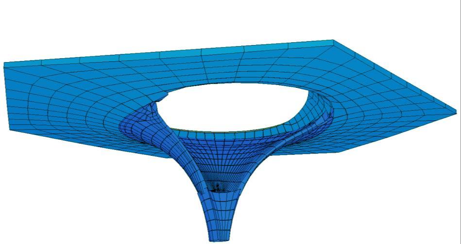
3 Main Station Stuttgart S21 Special characteristic: Doubly Curved Roof with Chalice Columns Designed by Ingenhoven Architects with contributions of Frei Paul Otto Complex double curved geometry of the roof with constantly varying thickness Filigree roof structure narrows down into single columns connecting the roof with the ground plate White Exposed Concrete C50/60 Boudary Conditions Varying subsoil stratification Structure sensitivity to settlements High concentrated loads Difficult Site constraints Crossing of underground line Construction divided into twenty construction sections Copyright Aldinger & Wolf

4 Main Station Stuttgart S

5 Main Station Stuttgart S

6 Geometry
7 Geometry

8 Geometry
9 Geometry
10 Geometry

11 Geometry


12 Main Station Stuttgart S21 Construction sections in the new central train station Section showing one construction section (area of BA 8 to BA14)

13 Building Structure with foundation and soil strata doubly curved roof with chalice column Trough Cast-in-situ Concrete piles with enlarged pile base

14 Building Structure with foundation and soil strata
15 Interconnecting geotechnical and structural design S-Model of Shell Structure Support conditions from trough by springs S-Modell of Trough Support conditions from foundation by springs Loads applied from shell structure G-Modell Trog mit Gründung Ermittlung der Auflagerbedingungen Ansatz Einwirkungen aus Schalendach

16 Interconnecting geotechnical and structural design S-Model of Shell Structure Support conditions from trough by springs S-Modell of Trough Support conditions from foundation by springs Loads applied from shell structure G-Modell of Trough and Foundation Determination of support condition Loads applied from shell structure

17 Interconnecting geotechnical and structural design S-Model of Shell Structure and Trough Support conditions from foundation by springs G-Modell of Trough and Foundation Determination of support condition Loads applied from shell structure

18 Interconnecting geotechnical and structural design S-Model of Shell Structure and Trough Support conditions from foundation by springs Applied as weightless Interaction loads from S-Model G-Modell of Trough and Foundation Determination of support condition Loads applied from shell structure
19 Interconnecting geotechnical and structural design Beam element S-Model of Shell Structure and Trough Support conditions from foundation by springs Shell Structure and Trough modelled as Finite Shell Elements Chalice Columns in connection to base plate modelled as Beam Element Applied as weightless Interaction loads from S-Model G-Modell of Trough and Foundation Determination of support condition Loads applied from shell structure Soil and structure are discretized with 10-node tetrahedral elements
20 Interconnecting geotechnical and structural design Beam element S-Model of Shell Structure and Trough Support conditions from foundation by springs Shell Structure and Trough modelled as Finite Shell Elements Chalice Columns in connection to base plate modelled as Beam Element Applied as weightless Interaction loads from S-Model G-Modell of Trough and Foundation Determination of support condition Loads applied from shell structure Soil and structure are discretized with 10-node tetrahedral elements Shell Structure and chalice columns simplified
21 Interconnecting geotechnical and structural design Beam element S-Model of Shell Structure and Trough Support conditions from foundation by springs Shell Structure and Trough modelled as Finite Shell Elements Chalice Columns in connection to base plate modelled as Beam Element Applied as weightless Interaction loads from S-Model G-Modell of Trough and Foundation Determination of support condition Loads applied from shell structure Soil and structure are discretized with 10-node tetrahedral elements Shell Structure and chalice columns simplified Piles are modeled with empedded beam elements (Empedded Pile) Embedded Pile Enlarged piles base: Empedded pile in zone with improved stiffness values

 Serviceability analyses of")

22 Interconnecting geotechnical and structural design G-Modell S-Modell Determination of subgrade reaction modulus for the base plate and spring stiffness for the piles Design for load-bearing capacity of the soil around the piles ( external capacity in ULS) Analysis of bearing capacity of the ground while neglecting the piles (ULS) Serviceability analyses of the foundation in regard to compliance with the requirements on limitation of deformation Design of Structure in ULS and SLS Design for inner capacity of piles in ULS and SLS


23 Interconnecting geotechnical and structural design G-Modell S-Modell Iterative adaption of geological and structural model: Support reaction and deformation are calibrated in an iterative approach Calculated settlements and pile reactions should not differ more than a maximum of 10% under a specified load combination Resulting deformations must be comparable


24 Geotechnical Model Subdeviding the 450m long concourse


25 Geotechnical Model FE-mesh around pile groups Limiting surfaces for discretising the FE mesh around pile groups FE mesh around pile groups
![Vertikalverformung uz [mm] Geotechnical Model 3D FE model Drained analyses based on](/docs-images/88/115710565/images/26-0.jpg "effective stress as well as effective stiffness and shear strength parameters")
 Soils modelled")

![Vertikallast Fz [kn] 0 1000 2000 3000 4000 5000 6000 7000 8000 9000 10000 11000 0 10](/docs-images/88/115710565/images/26-4.jpg "20 30 40 50 60 70 80 90 100 qs, berechnet qb, berechnet R, berechnet qs,gemessen")
26 Vertikalverformung uz [mm] Geotechnical Model 3D FE model Drained analyses based on effective stress as well as effective stiffness and shear strength parameters Mathematical modelling for groundwater flow in response to excavation and simultaneous drainage is based on Darcy s law (coupled analysis) Soils modelled using the Hardening Soil Model with small strain stiffness parameters were determined using results from field and laboratory tests and recognised correlations Vertikallast Fz [kn] qs, berechnet qb, berechnet R, berechnet qs,gemessen qb,gemessen R,gemessen
27 Geotechnical Model Soils modelled using the Hardening Soil Model with small strain stiffness Parameters Material TA WS DRM/BH GG Unit weights parameters were determined using results from field and laboratory tests and recognised correlations unsat / sat Colour Soil Model HSS HSS HSS HSS [kn/m³] Pile Stiffness [MN/m²] TA WS Cohesion c' [kn/m²] 22,5 27,5 22,5 25 Internal friction ' [ ] K0-value for normal consolidation nc K 0 [-] 0,617 0,538 0,617 0,577 Power for stress-level dependency of stiffness m [-] 0,6 0,6 0,6 0, DRM/BH Poisson's ratio for unloading-reloading ur [-] 0,2 0,2 0,2 0,2 Reference stress for stiffness p ref [kn/m²] Tangent stiffness ref E oed [MN/m²] Secant stiffness ref E 50 [MN/m²] Unloading-reloading stiffness ref E ur [MN/m²] Shear modulus at very small strains ref G 0 [MN/m²] 20 21, Shear strain at which is GS = 0,722G0 0,7 [-] 1,0E-4 1,0E-4 3,0E-4 3,0E-4 Level [mnn] GG E50 Eoed Eur G

 a) c) Moment a) b)")

28 Supporting studies while preparing the geotechnical model a) b) a) c) Moment a) b) b) c) c) Verticale displacement
 Simulation of foundation soil stress around the pile base by expanding a droplet-shaped cluster volume of a base 5% horizontally und 25%")

29 Calibration load bearing behavior of Piles on Pile Load Test Model of sample load on a driven pile in a pile group (TM1) Using volume piles (TM1 VP) Simulation of foundation soil stress around the pile base by expanding a droplet-shaped cluster volume of a base 5% horizontally und 25% vertically - separately for each pile. Pile base was held vertically in a permanent position during volume extension at the upper side where it transitions into the pile shaft TM1 VP initial stress generated by volume expansion [kn/m²], left σ1, right σ3, 3D FE model, isometric view
 Using embedded piles (TM1 EP) Implementing zone")
 around an embedded pile with a diameter of 2 meters for the enlarged pile base")

30 Calibration load bearing behavior of Piles on Pile Load Test Model of sample load on a driven pile in a pile group (TM1) Using embedded piles (TM1 EP) Implementing zone with improved stiffness values ( factor of 4; refer Gabers et al. 2014) around an embedded pile with a diameter of 2 meters for the enlarged pile base Increased pile shaft diameter to adjust stiffness of shaft friction in reference to test result Embedded Pile pile shaft Embedded Pile Pile base TM1 EP TM1 EP pile group in the model
31 Settlement of pile head [cm] Calibration load bearing behavior of Piles on Pile Load Test Model of sample load on a driven pile in a pile group (TM1) Comparison between the RSC from sample load against RSC from recalculations Force [MN] 0,0 0,5 1,0 1,5 2,0 2,5 3,0 3,5 4,0 0,00 0,25 0,50 0,75 1,00 1,25 characteristic RSC from Pile load Test (Smoltczyk & Partner GmbH) RSC, re-calculated with VP with volume expansion at pile base RSC, re-calculated with EP and Zones with improved Stiffness
32 Study of load bearing behavior of volume piles and embedded piles while combined with the bas slab - (TM2) Using same configuration of volume piles and empedded piles Top view of TM 2 Ground floor plan of the piles foundation in TM
33 Study of load bearing behavior of volume piles and embedded piles while combined with the bas slab - (TM2) Using same configuration of volume piles and empedded piles Top view of TM 2 Ground floor plan of the piles foundation in TM 2 FE-Model TM1 VP
34 Study of load bearing behavior of volume piles and embedded piles while combined with the bas slab - (TM2) Using same configuration of volume piles and empedded piles Pile group below chalice column Ground floor plan of the piles foundation in TM 2 FE-Model TM1 VP
35 Settlement of pile head [m] Settlement of pile head [m] Study of load bearing behavior of volume piles and embedded piles while combined with the bas slab - (TM2) Comparison of resistance-settlement curve of the piles resistance due to skin friction Volume Piles Sum of skin friction [kn] Embedded Piles Sum of skin friction [kn] Construction of base plate Construction of base plate Pile group below chalice column
36 settlement of pile base [m] Study of load bearing behavior of volume piles and embedded piles while combined with the bas slab - (TM2) Comparison of resistance-settlement curve of the piles pile base resistance Volume piles Force at pile base [kn] ,000-1, Embedded Piles D65 Force at pile base [kn] ,000-1, Construction of base plate settlement of pile base [m] Construction of base plate Pile group below chalice column
37 Settlement of pile head [m] Settlement of pile head [m] Study of load bearing behavior of volume piles and embedded piles while combined with the bas slab - (TM2) Comparison of resistance-settlement curve of the piles pile resistance Volume Piles Force at pile head [kn] ,000-1, Embedded Piles Force at pile head [kn] ,000-1, Construction of base plate Construction of base plate Pile group below chalice column


38 Study of load bearing behavior of volume piles and embedded piles while combined with the bas slab - (TM2) Comparison of vertical displacements [mm] Volume Piles Embedded Piles TM2 Iso surfaces of vertical displacements in mm at colunm load of 32MN
39 Study of load bearing behavior of volume piles and embedded piles while combined with the bas slab - (TM2) Comparison of vertical stresses at soil below base slab [kn/m²] Volume Piles Embedded Piles TM2 vertical effective stresses below base slab in kn/m² at column load of 32MN
40 Study of load bearing behavior of volume piles and embedded piles while combined with the bas slab - (TM2) Embedded Pile D51 - Pfahlfedern innerhalb der Comparison of axial pile spring stiffness Pfahlgruppe (letzte Phase abzügl. Platte) Embedded Pile D65 - Pfahlfedern innerhalb der Pfahlgruppe (letzte Phase, Plaxis-Parameter) Volumen Piles Embedded Piles TM2 axial pile spring stiffness in MN/m, Pile group below chalice column at column load of 32MN
 28.09.")
41 Consideration of construction phase G-Modell with calculation phase Floor excavation BA16 Trough BA16 Trough with chalice supports BA16 & 17 Shell roof BA16 &17, BW BA19 Final excavation BA18 & BA15 Trough BA18 & BA15 Chalice supports BA18 & BA15 Closing the shell roof Backfill and landfill Figure 1: Geotechnical model in selected phases of calculation (examples)
 Bedding Stress [kn/m²] Settlement [mm] Bedding Spring [kn/m³] 28.09.")
42 Calibration of Geotechnical and Structural Model Base reactions from G-Model (Phase 26 - DL+ 1/3LL) Bedding Stress [kn/m²] Settlement [mm] Bedding Spring [kn/m³]
43 Calibration of Geotechnical and Structural Model Example of pile springs from G-Model [MN/m²]


44 Calibration of Geotechnical and Structural Model Comparison of bedding stress G-Modell S-Modell kn/m²
![iebung [mm] Knotenverschiebung [mm] Knotenverschiebung [mm] Knotenverschiebung [mm] Calibration of Geotechnical and Structural Model Comparison of settlements cross sections A7-80 -70-60 -50-40](/docs-images/88/115710565/images/45-0.jpg "-30-20 -10 0 10 20 0 A7 A7 A8 S-Model -5-10 -15 Südseite G-Model Knotenkoordinate [m] Nordseite -20-25 -30 Bodenplattenprofil Setzungen CDM Setzungen WSS A8-80 -70-60 -50-40 -30-20 -10 0 10 20 0 A8")
45 iebung [mm] Knotenverschiebung [mm] Knotenverschiebung [mm] Knotenverschiebung [mm] Calibration of Geotechnical and Structural Model Comparison of settlements cross sections A A7 A7 A8 S-Model Südseite G-Model Knotenkoordinate [m] Nordseite Bodenplattenprofil Setzungen CDM Setzungen WSS A A8 G-Model Südseite S-Model Knotenkoordinate [m] Nordseite Bodenplattenprofil Setzungen CDM Setzungen WSS AF BA12 Knotenkoordinate [m] BA13 BA14-25 Bodenplattenprofil Setzungen CDM Setzungen WSS AC/AD
46 Calibration of Geotechnical and Structural Model Comparison of pile reactions Pfahlkräfte [MN] Stelle G-Modell T-Modell Abweichung Abweichung % (CDM) (WSS) A4 1,9 1,8 0,1 5% A5 1,2 1,4 0,2 14% A6 1,4 1,6 0,2 13% B5a 0,9 0,9 0,0 0% B5b 1,4 1,3 0,1 7% C6a 0,8 0,8 0,0 0% C6b 1,2 1,2 0,0 0% D5a 0,9 0,8 0,1 11% D5b 1,3 1,1 0,2 15% E6a 0,8 0,8 0,0 0% E6b 1,4 1,4 0,0 0% F4 1,9 1,9 0,0 0% F5 1,5 1,4 0,1 7% F6 1,7 1,6 0,1 6% Verformung [mm] Stelle G-Modell T-Modell Abweichung Abweichung % (CDM) (WSS) A % A % A % B % C % D % E % F % F % F %
 Model 28.09.")
47 Structural Models 3D FE-Model (Sofistik) Linear Elastic Analysis Shell Elements + Beam Elements Main (overall) Model

48 Structural Models Partial Models
49 Structural Models Construction Phase Model Phase

50 Structural Models Construction Phase Model Phase
51 Structural Models Construction Phase Model Phase
52 Structural Models Construction Phase Model Phase
53 Structural Models Construction Phase Model Phase
54 Structural Models Construction Phase Model Phase
55 Structural Models Construction Phase Model Phase
56 Structural Models Construction Phase Model Phase
57 Structural Models Construction Phase Model Phase

58 Structural Design Main Loadings Dead Loads Earth pressure and ground water pressure Train traffic loading Temperature and shrinkage Eathquake F DL = 24 MN F DL = 35 MN


59 Structural Design Main Loadings Dead Loads Earth pressure and ground water pressure Train traffic loading Temperature and shrinkage Eathquake

60 Structural Design Main Loadings Dead Loads Earth pressure and ground water pressure Train traffic loading Temperature and shrinkage Eathquake

61 Structural Design Main Loadings Dead Loads Earth pressure and ground water pressure Train traffic loading Temperature and shrinkage Eathquake
62 Structural Design Main Loadings Dead Loads Earth pressure and ground water pressure Train traffic loading Temperature and shrinkage Eathquake

63 Structural Design Main Loadings Dead Loads Earth pressure and ground water pressure Train traffic loading Temperature and shrinkage Eathquake

64 Structural Design Main Loadings Dead Loads Earth pressure and ground water pressure Train traffic loading Temperature and shrinkage Eathquake
65 Structural Design Main Loadings Up to 240 single loadcases for one partial model 7 different design combinations Additional sub-combinations LF Bezeichnung Gruppe LF Bezeichnung Gruppe LF Bezeichnung Gruppe 1 Eigengewicht G1 81 Anbindebauwerk BA9 - Ständige Lasten G1 321 Temperatur +15K End T1 2 Ausbaulast Dach G1 82 Nutz-/Verkehrslasten G1 322 Temperatur -10K End T1 3 Eigengewicht Lichtaugen G1 323 Temp-Unterschied End Sommer I T1 5 Ausbaulast Bodenplatte G1 101 Verkehrslast Schalendach Q4 324 Temp-Unterschied End Sommer II T1 7 Ausbaulast Fertigteile Bodenplatte G1 102 Verkehrslast auf Lichtaugen Q4 325 Temp-Unterschied End Winter I T1 8 Eigengewicht + Ausbaulast Rolltreppen G1 104 Verkehrslast Verteilersteg Q4 326 Temp-Unterschied End Winter II T1 9 Eigengewicht + Ausbaulast Festtreppen G1 105 Verkehrslast Rucksack Q4 10 Eigengewicht + Ausbaulast Aufzüge G1 111 Pratzenlast 1a Q8 331 Temperatur +15K Bau T3 11 Eigengewicht + Ausbaulast Verteilersteg A,B G1 112 Pratzenlast 1b Q8 332 Temperatur -10K Bau T3 12 Eigengewicht + Ausbaulast Rucksack G1 113 Pratzenlast 2a Q8 333 Temp-Unterschied Bau Sommer I T3 13 Eigengewicht + Ausbau KGK-Schale G1 114 Pratzenlast 2b Q8 334 Temp-Unterschied Bau Sommer II T3 335 Temp-Unterschied Bau Winter I T3 21 Eigengewicht Dach gewichtslos G1 115 Müllfahrzeug 1 Q9 336 Temp-Unterschied Bau Winter II T3 116 Müllfahrzeug 2 Q9 15 Schnee auf Dach S1 117 Müllfahrzeug 3 Q9 Temperatur Überlagerung 16 Schnee auf Lichtaugen S1 341 Temp End Sommer 1 (LF *LF323) T1 17 Schnee KGK-Schale I S LM71 Streckenlast Q6 342 Temp End Sommer 2 (LF *LF321) T1 18 Schnee KGK-Schale II S LM71 Streckenlast Q6 343 Temp End Sommer 3 (LF *LF324) T1 19 Schnee KGK-Schale III S LM71 Streckenlast Q6 344 Temp End Sommer 4 (LF *LF321) T LM71 Streckenlast Q6 345 Temp End Winter 1 (LF *LF325) T1 30 Schwinden -10K Q1 346 Temp End Winter 2 (LF *LF322) T1 31 Schwinden Bodenplatte K Dach K Q LM71 Achsüberlast Q6 347 Temp End Winter 3 (LF *LF326) T1 32 Schwinden Bodenplatte K Dach K Q LM71 Achsüberlast Q6 348 Temp End Winter 4 (LF *LF322) T LM71 Achsüberlast Q6 33 Wind KGK-Schale I W LM71 Achsüberlast Q6 351 Temp End Sommer 1 (LF *LF333) T3 34 Wind KGK-Schale I W 352 Temp End Sommer 2 (LF *LF331) T3 35 Wind KGK-Schale I W SW/2 Q6 353 Temp End Sommer 3 (LF *LF334) T3 36 Wind KGK-Schale I W SW/2 Q6 354 Temp End Sommer 4 (LF *LF331) T3 37 Wind KGK-Schale I W SW/2 Q6 355 Temp End Winter 1 (LF *LF335) T SW/2 Q6 356 Temp End Winter 2 (LF *LF332) T3 41 Erddruck ständig mf G1 357 Temp End Winter 3 (LF *LF336) T3 42 Erddruck veränderlich I Nord Q2 231 Zugverkehr Horizontal + Q7 358 Temp End Winter 4 (LF *LF332) T3 43 Erddruck veränderlich I Süd Q2 232 Zugverkehr Horizontal - Q7 44 Erddruck veränderlich II Nord Q2 Temperatur Pfahlbemessung 45 Erddruck veränderlich II Süd Q Verkehrslast Bahnsteig Q5 361 Temperatur +15K End T Verkehrslast Bahnsteig Q5 362 Temperatur -10K End T1 363 Temp-Unterschied End Sommer I T1 252 Verkehrslast Technikkanal Rand Q5 364 Temp-Unterschied End Sommer II T1 51 Erddruck ständig of Q2 253 Verkehrslast Technikräume Q5 365 Temp-Unterschied End Winter I T1 52 Erddruck veränderlich I Nord Q2 254 Verkehrslast Rolltreppen Q5 366 Temp-Unterschied End Winter II T1 53 Erddruck veränderlich I Süd Q2 255 Verkehrslast Festtreppen Q5 54 Erddruck veränderlich II Nord Q2 256 Verkehrslast Aufzüge Q5 371 Temperatur +15K Bau T3 55 Erddruck veränderlich II Süd Q2 376 Temperatur -10K Bau T3 373 Temp-Unterschied Bau Sommer I T3 56 Wasserdruck HGW200 abzgl. Mindestwasserdruck Q3 374 Temp-Unterschied Bau Sommer II T3 57 Wasserdruck HGW200 Q3 375 Temp-Unterschied Bau Winter I T3 58 Mindestwasserdruck Q3 376 Temp-Unterschied Bau Winter II T3 61 Anprall Stütze Achse 5-AB A Temperatur Überlagerung 62 Anprall Stütze Achse 5-AB A 381 Temp End Sommer 1 (LF *LF363) T1 63 Anprall Stütze Achse 5-AB A 382 Temp End Sommer 2 (LF *LF361) T1 64 Anprall Stütze Achse 5-AB A 383 Temp End Sommer 3 (LF *LF364) T1 65 Anprall Stütze Achse 5-AD A 384 Temp End Sommer 4 (LF *LF361) T1 66 Anprall Stütze Achse 5-AD A 385 Temp End Winter 1 (LF *LF365) T1 67 Anprall Stütze Achse 5-AD A 386 Temp End Winter 2 (LF *LF362) T1 68 Anprall Stütze Achse 5-AD A 387 Temp End Winter 3 (LF *LF366) T1 69 Anprall Stütze Achse 6-AC A 388 Temp End Winter 4 (LF *LF362) T1 70 Anprall Stütze Achse 6-AC A 71 Anprall Stütze Achse 6-AC A 391 Temp End Sommer 1 (LF *LF373) T3 72 Anprall Stütze Achse 6-AC A 392 Temp End Sommer 2 (LF *LF371) T3 73 Anprall Stütze Achse 6-AE A 393 Temp End Sommer 3 (LF *LF374) T3 74 Anprall Stütze Achse 6-AE A 394 Temp End Sommer 4 (LF *LF371) T3 75 Anprall Stütze Achse 6-AE A 395 Temp End Winter 1 (LF *LF375) T3 76 Anprall Stütze Achse 6-AE A 396 Temp End Winter 2 (LF *LF372) T3 397 Temp End Winter 3 (LF *LF376) T3 398 Temp End Winter 4 (LF *LF372) T

66 Structural Design Variation of ground stiffness Variation of +/- 20% of spring stiffness locally and globally Leads up to 37 different bedding scenario for one building section BA
67 Structural Design Variation of ground stiffness Variation of +/- 20% of spring stiffness locally and globally Leads up to 37 different bedding scenario for one building section Iteration Generelle Bettungssituation Abweichung von mittlerer Bettung Gruppe Abweichung Bereich 1 MAX Trogwand Nord Rechts ca. -20% BA12 2 MAX Trogwand Sued Rechts ca. -20% BA12 3 MAX Mittelstuetze Achse 6 ca. -20% BA12 4 MAX Randstuetze Achse 6 ca. -20% BA12 5 MAX Trogwand Nord Links ca. -20% BA13 6 MAX Trogwand Nord Rechts ca. -20% BA13 7 MAX Trogwand Sued Links ca. -20% BA13 8 MAX Trogwand Sued Rechts ca. -20% BA13 9 MAX Mittelstuetze Achse 7 ca. -20% BA13 10 MAX Mittelstuetze Achse 8 ca. -20% BA13 11 MAX Randstuetze Achse 7 ca. -20% BA13 12 MAX Randstuetze Achse 8 ca. -20% BA13 13 MAX Trogwand Nord ca. -20% BA14 14 MAX Trogwand Sued ca. -20% BA14 15 MAX Mittelstuetze Achse 9 ca. -20% BA14 16 MAX Randstuetze Achse 9 ca. -20% BA14 17 MIN Trogwand Nord Rechts ca. +20% BA12 18 MIN Trogwand Sued Rechts ca. +20% BA12 19 MIN Mittelstuetze Achse 6 ca. +20% BA12 20 MIN Randstuetze Achse 6 ca. +20% BA12 21 MIN Trogwand Nord Links ca. +20% BA13 22 MIN Trogwand Nord Rechts ca. +20% BA13 23 MIN Trogwand Sued Links ca. +20% BA13 24 MIN Trogwand Sued Rechts ca. +20% BA13 25 MIN Mittelstuetze Achse 7 ca. +20% BA13 26 MIN Mittelstuetze Achse 8 ca. +20% BA13 27 MIN Randstuetze Achse 7 ca. +20% BA13 28 MIN Randstuetze Achse 8 ca. +20% BA13 29 MIN Trogwand Nord ca. +20% BA14 30 MIN Trogwand Sued ca. +20% BA14 31 MIN Mittelstuetze Achse 9 ca. +20% BA14 32 MIN Randstuetze Achse 9 ca. +20% BA14 33 MID BA13 ca. -20% BA13 34 MID BA13 ca. +20% BA13 35 MID Loungepfähle ca. -20% Alle 36 MID Loungepfähle ca. +20% Alle 37 MID Alle - Alle

68 Structural Design Variation of ground stiffness Variation of +/- 20% of spring stiffness locally and globally Leads up to 37 different bedding scenario for one building section Iteration Generelle Bettungssituation Abweichung von mittlerer Bettung Gruppe Abweichung Bereich 1 MAX Trogwand Nord Rechts ca. -20% BA12 2 MAX Trogwand Sued Rechts ca. -20% BA12 3 MAX Mittelstuetze Achse 6 ca. -20% BA12 4 MAX Randstuetze Achse 6 ca. -20% BA12 5 MAX Trogwand Nord Links ca. -20% BA13 6 MAX Trogwand Nord Rechts ca. -20% BA13 7 MAX Trogwand Sued Links ca. -20% BA13 8 MAX Trogwand Sued Rechts ca. -20% BA13 9 MAX Mittelstuetze Achse 7 ca. -20% BA13 10 MAX Mittelstuetze Achse 8 ca. -20% BA13 11 MAX Randstuetze Achse 7 ca. -20% BA13 12 MAX Randstuetze Achse 8 ca. -20% BA13 13 MAX Trogwand Nord ca. -20% BA14 14 MAX Trogwand Sued ca. -20% BA14 15 MAX Mittelstuetze Achse 9 ca. -20% BA14 16 MAX Randstuetze Achse 9 ca. -20% BA14 17 MIN Trogwand Nord Rechts ca. +20% BA12 18 MIN Trogwand Sued Rechts ca. +20% BA12 19 MIN Mittelstuetze Achse 6 ca. +20% BA12 20 MIN Randstuetze Achse 6 ca. +20% BA12 21 MIN Trogwand Nord Links ca. +20% BA13 22 MIN Trogwand Nord Rechts ca. +20% BA13 23 MIN Trogwand Sued Links ca. +20% BA13 24 MIN Trogwand Sued Rechts ca. +20% BA13 25 MIN Mittelstuetze Achse 7 ca. +20% BA13 26 MIN Mittelstuetze Achse 8 ca. +20% BA13 27 MIN Randstuetze Achse 7 ca. +20% BA13 28 MIN Randstuetze Achse 8 ca. +20% BA13 29 MIN Trogwand Nord ca. +20% BA14 30 MIN Trogwand Sued ca. +20% BA14 31 MIN Mittelstuetze Achse 9 ca. +20% BA14 32 MIN Randstuetze Achse 9 ca. +20% BA14 33 MID BA13 ca. -20% BA13 34 MID BA13 ca. +20% BA13 35 MID Loungepfähle ca. -20% Alle 36 MID Loungepfähle ca. +20% Alle 37 MID Alle - Alle
69 Structural Design Variation of ground stiffness Variation of +/- 20% of spring stiffness locally and globally Leads up to 37 different bedding scenario for one building section Iteration Generelle Bettungssituation Abweichung von mittlerer Bettung Gruppe Abweichung Bereich 1 MAX Trogwand Nord Rechts ca. -20% BA12 2 MAX Trogwand Sued Rechts ca. -20% BA12 3 MAX Mittelstuetze Achse 6 ca. -20% BA12 4 MAX Randstuetze Achse 6 ca. -20% BA12 5 MAX Trogwand Nord Links ca. -20% BA13 6 MAX Trogwand Nord Rechts ca. -20% BA13 7 MAX Trogwand Sued Links ca. -20% BA13 8 MAX Trogwand Sued Rechts ca. -20% BA13 9 MAX Mittelstuetze Achse 7 ca. -20% BA13 10 MAX Mittelstuetze Achse 8 ca. -20% BA13 11 MAX Randstuetze Achse 7 ca. -20% BA13 12 MAX Randstuetze Achse 8 ca. -20% BA13 13 MAX Trogwand Nord ca. -20% BA14 14 MAX Trogwand Sued ca. -20% BA14 15 MAX Mittelstuetze Achse 9 ca. -20% BA14 16 MAX Randstuetze Achse 9 ca. -20% BA14 17 MIN Trogwand Nord Rechts ca. +20% BA12 18 MIN Trogwand Sued Rechts ca. +20% BA12 19 MIN Mittelstuetze Achse 6 ca. +20% BA12 20 MIN Randstuetze Achse 6 ca. +20% BA12 21 MIN Trogwand Nord Links ca. +20% BA13 22 MIN Trogwand Nord Rechts ca. +20% BA13 23 MIN Trogwand Sued Links ca. +20% BA13 24 MIN Trogwand Sued Rechts ca. +20% BA13 25 MIN Mittelstuetze Achse 7 ca. +20% BA13 26 MIN Mittelstuetze Achse 8 ca. +20% BA13 27 MIN Randstuetze Achse 7 ca. +20% BA13 28 MIN Randstuetze Achse 8 ca. +20% BA13 29 MIN Trogwand Nord ca. +20% BA14 30 MIN Trogwand Sued ca. +20% BA14 31 MIN Mittelstuetze Achse 9 ca. +20% BA14 32 MIN Randstuetze Achse 9 ca. +20% BA14 33 MID BA13 ca. -20% BA13 34 MID BA13 ca. +20% BA13 35 MID Loungepfähle ca. -20% Alle 36 MID Loungepfähle ca. +20% Alle 37 MID Alle - Alle
70 Structural Design Variation of ground stiffness Variation of +/- 20% of spring stiffness locally and globally Leads up to 37 different bedding scenario for one building section Iteration Generelle Bettungssituation Abweichung von mittlerer Bettung Gruppe Abweichung Bereich 1 MAX Trogwand Nord Rechts ca. -20% BA12 2 MAX Trogwand Sued Rechts ca. -20% BA12 3 MAX Mittelstuetze Achse 6 ca. -20% BA12 4 MAX Randstuetze Achse 6 ca. -20% BA12 5 MAX Trogwand Nord Links ca. -20% BA13 6 MAX Trogwand Nord Rechts ca. -20% BA13 7 MAX Trogwand Sued Links ca. -20% BA13 8 MAX Trogwand Sued Rechts ca. -20% BA13 9 MAX Mittelstuetze Achse 7 ca. -20% BA13 10 MAX Mittelstuetze Achse 8 ca. -20% BA13 11 MAX Randstuetze Achse 7 ca. -20% BA13 12 MAX Randstuetze Achse 8 ca. -20% BA13 13 MAX Trogwand Nord ca. -20% BA14 14 MAX Trogwand Sued ca. -20% BA14 15 MAX Mittelstuetze Achse 9 ca. -20% BA14 16 MAX Randstuetze Achse 9 ca. -20% BA14 17 MIN Trogwand Nord Rechts ca. +20% BA12 18 MIN Trogwand Sued Rechts ca. +20% BA12 19 MIN Mittelstuetze Achse 6 ca. +20% BA12 20 MIN Randstuetze Achse 6 ca. +20% BA12 21 MIN Trogwand Nord Links ca. +20% BA13 22 MIN Trogwand Nord Rechts ca. +20% BA13 23 MIN Trogwand Sued Links ca. +20% BA13 24 MIN Trogwand Sued Rechts ca. +20% BA13 25 MIN Mittelstuetze Achse 7 ca. +20% BA13 26 MIN Mittelstuetze Achse 8 ca. +20% BA13 27 MIN Randstuetze Achse 7 ca. +20% BA13 28 MIN Randstuetze Achse 8 ca. +20% BA13 29 MIN Trogwand Nord ca. +20% BA14 30 MIN Trogwand Sued ca. +20% BA14 31 MIN Mittelstuetze Achse 9 ca. +20% BA14 32 MIN Randstuetze Achse 9 ca. +20% BA14 33 MID BA13 ca. -20% BA13 34 MID BA13 ca. +20% BA13 35 MID Loungepfähle ca. -20% Alle 36 MID Loungepfähle ca. +20% Alle 37 MID Alle - Alle

71 Structural Design Variation of ground stiffness Variation of +/- 20% of spring stiffness locally and globally Leads up to 37 different bedding scenario for one building section Iteration Generelle Bettungssituation Abweichung von mittlerer Bettung Gruppe Abweichung Bereich 1 MAX Trogwand Nord Rechts ca. -20% BA12 2 MAX Trogwand Sued Rechts ca. -20% BA12 3 MAX Mittelstuetze Achse 6 ca. -20% BA12 4 MAX Randstuetze Achse 6 ca. -20% BA12 5 MAX Trogwand Nord Links ca. -20% BA13 6 MAX Trogwand Nord Rechts ca. -20% BA13 7 MAX Trogwand Sued Links ca. -20% BA13 8 MAX Trogwand Sued Rechts ca. -20% BA13 9 MAX Mittelstuetze Achse 7 ca. -20% BA13 10 MAX Mittelstuetze Achse 8 ca. -20% BA13 11 MAX Randstuetze Achse 7 ca. -20% BA13 12 MAX Randstuetze Achse 8 ca. -20% BA13 13 MAX Trogwand Nord ca. -20% BA14 14 MAX Trogwand Sued ca. -20% BA14 15 MAX Mittelstuetze Achse 9 ca. -20% BA14 16 MAX Randstuetze Achse 9 ca. -20% BA14 17 MIN Trogwand Nord Rechts ca. +20% BA12 18 MIN Trogwand Sued Rechts ca. +20% BA12 19 MIN Mittelstuetze Achse 6 ca. +20% BA12 20 MIN Randstuetze Achse 6 ca. +20% BA12 21 MIN Trogwand Nord Links ca. +20% BA13 22 MIN Trogwand Nord Rechts ca. +20% BA13 23 MIN Trogwand Sued Links ca. +20% BA13 24 MIN Trogwand Sued Rechts ca. +20% BA13 25 MIN Mittelstuetze Achse 7 ca. +20% BA13 26 MIN Mittelstuetze Achse 8 ca. +20% BA13 27 MIN Randstuetze Achse 7 ca. +20% BA13 28 MIN Randstuetze Achse 8 ca. +20% BA13 29 MIN Trogwand Nord ca. +20% BA14 30 MIN Trogwand Sued ca. +20% BA14 31 MIN Mittelstuetze Achse 9 ca. +20% BA14 32 MIN Randstuetze Achse 9 ca. +20% BA14 33 MID BA13 ca. -20% BA13 34 MID BA13 ca. +20% BA13 35 MID Loungepfähle ca. -20% Alle 36 MID Loungepfähle ca. +20% Alle 37 MID Alle - Alle
72 Structural Design Variation of ground stiffness Variation of +/- 20% of spring stiffness locally and globally Leads up to 37 different bedding scenario for one building section Iteration Generelle Bettungssituation Abweichung von mittlerer Bettung Gruppe Abweichung Bereich 1 MAX Trogwand Nord Rechts ca. -20% BA12 2 MAX Trogwand Sued Rechts ca. -20% BA12 3 MAX Mittelstuetze Achse 6 ca. -20% BA12 4 MAX Randstuetze Achse 6 ca. -20% BA12 5 MAX Trogwand Nord Links ca. -20% BA13 6 MAX Trogwand Nord Rechts ca. -20% BA13 7 MAX Trogwand Sued Links ca. -20% BA13 8 MAX Trogwand Sued Rechts ca. -20% BA13 9 MAX Mittelstuetze Achse 7 ca. -20% BA13 10 MAX Mittelstuetze Achse 8 ca. -20% BA13 11 MAX Randstuetze Achse 7 ca. -20% BA13 12 MAX Randstuetze Achse 8 ca. -20% BA13 13 MAX Trogwand Nord ca. -20% BA14 14 MAX Trogwand Sued ca. -20% BA14 15 MAX Mittelstuetze Achse 9 ca. -20% BA14 16 MAX Randstuetze Achse 9 ca. -20% BA14 17 MIN Trogwand Nord Rechts ca. +20% BA12 18 MIN Trogwand Sued Rechts ca. +20% BA12 19 MIN Mittelstuetze Achse 6 ca. +20% BA12 20 MIN Randstuetze Achse 6 ca. +20% BA12 21 MIN Trogwand Nord Links ca. +20% BA13 22 MIN Trogwand Nord Rechts ca. +20% BA13 23 MIN Trogwand Sued Links ca. +20% BA13 24 MIN Trogwand Sued Rechts ca. +20% BA13 25 MIN Mittelstuetze Achse 7 ca. +20% BA13 26 MIN Mittelstuetze Achse 8 ca. +20% BA13 27 MIN Randstuetze Achse 7 ca. +20% BA13 28 MIN Randstuetze Achse 8 ca. +20% BA13 29 MIN Trogwand Nord ca. +20% BA14 30 MIN Trogwand Sued ca. +20% BA14 31 MIN Mittelstuetze Achse 9 ca. +20% BA14 32 MIN Randstuetze Achse 9 ca. +20% BA14 33 MID BA13 ca. -20% BA13 34 MID BA13 ca. +20% BA13 35 MID Loungepfähle ca. -20% Alle 36 MID Loungepfähle ca. +20% Alle 37 MID Alle - Alle


73 Construction Information Generating reinforcement drawings

74 Construction Information Generating reinforcement drawings
75 Construction Information Generating reinforcement drawings

76 Construction Information Generating reinforcement drawings


77 Construction Information Generating reinforcement drawings

78 Construction Information Positive and negative formwork


79 Site Photos


80 Site Photos
81 Monitoring Load bearing behaviour of the foundation is monitored in selected areas of the building during construction Reason: Verification verify the geotechnical model and calculation methods Early detection of possible critical conditions Review of settlement compared to the final settlement predicted and in the construction phase Quality assurance and preservation of evidence

82 Vielen Dank! 84
Junction of a Blended Wing Body Aircraft
 Topology Optimization of the Wing-Cabin Junction of a Blended Wing Body Aircraft Bin Wei M.Sc. Ögmundur Petersson M.Sc. 26.11.2010 Challenge of wing root design Compare to conventional aircraft: Improved
Newest Generation of the BS2 Corrosion/Warning and Measurement System
 Newest Generation of the BS2 Corrosion/Warning and Measurement System BS2 System Description: BS2 CorroDec 2G is a cable and energyless system module range for detecting corrosion, humidity and prevailing
2011 European HyperWorks Technology Conference
 2011 European HyperWorks Technology Conference Topology Optimization Methods applied to Automotive Transmission Housings 1 Agenda Introduction - Corporate Information - overview Topology Optimization for
ISEA RWTH Aachen Electric Bus Simulation
 ISEA RWTH Aachen Electric Bus Simulation Finding the Optimal Technical Configuration 05.04.2017 Fabian Meishner Lehrstuhl für Elektrochemische Energiewandlung und 1 Speichersystemtechnik Electric Bus Simulation
Dynamic Hybrid Simulation
 Dynamic Hybrid Simulation Comparison of different approaches in HEV-modeling GT-SUITE Conference 12. September 2012, Frankfurt/Main Institut für Verbrennungsmotoren und Kraftfahrwesen Universität Stuttgart
Behaviour of slab track under extreme stress conditions
 ,, 22. February 2005 13:25-13:50 Behaviour of slab track under Dr.-Ing. Lutz Vogt PD Dr.-Ing. Peter-Andreas von Wolffersdorff Dr.-Ing. Erich Rehfeld phone: +49 (0) 351 824 13 50 http://www.baugrund-dresden.de
ZnO-Arresters for Overvoltage Protection in Pulsed Power Circuits
 European Electromagnetic Launch Society 12th Topical Meeting 10th to 12th September 2001, Ayr ZnO-Arresters for Overvoltage Protection in Pulsed Power Circuits Ulrich Braunsberger Institut für Hochspannungstechnik
Wakefield computation of PETRAIII taper section Laura Lünzer
 Wakefield computation of PETRAIII taper section Laura Lünzer 16. Dezember 2011 TU Darmstadt Fachbereich 18 Institut Theorie Elektromagnetischer Felder Laura Lünzer Geometry of tapered structure Undulator
Material parameters on rheological studies of plasters and joint compounds Regensburg, March 11, 2009
 Material parameters on rheological studies of plasters and joint compounds Regensburg, March 11, 2009 Steffen Schneider, Forschung & Entwicklung, Abteilung Putze und Spachtelmassen 1 Steffen Schneider,
Production of titanium structural parts for aeroplanes - Requirements for high performance milling -
 Production of titanium structural parts for aeroplanes - Requirements for high performance milling - Prof. Dr.-Ing. B. Denkena, T. Grove Hannover, April 12th 2013 Structure Titanium a high performance
FEM Isoparametric Concept
 FEM Isoparametric Concept home/lehre/vl-mhs--e/cover_sheet.tex. p./26 Table of contents. Interpolation Functions for the Finite Elements 2. Finite Element Types 3. Geometry 4. Interpolation Approach Function
Prüfung von Rotorblättern für Windkraftanlagen
 Prüfung von Rotorblättern für Windkraftanlagen Florian Sayer www.iwes.fraunhofer.de Kompetenzzentrum Rotorblatt Neue Testverfahren Neue Simulationsverfahren Neue Rotorblätter Material- und Technologieentwicklung
A parameterised 3D-Structure-Model for the state of Bremen (Germany)
") A parameterised 3D-Structure-Model for the state of Bremen (Germany) An application for detailled groundwater flow and transport studies Bremen Geography and Geology 3 Bremen Geography and Geology 4 Structual
A parameterised 3D-Structure-Model for the state of Bremen (Germany) An application for detailled groundwater flow and transport studies Bremen Geography and Geology 3 Bremen Geography and Geology 4 Structual
Integration of Simulation and Testing in Power Train Engineering Based on the Example of the Dual Mass Flywheel
 Integration of Simulation and Testing in Power Train Engineering Based on the Example of the Dual Mass Flywheel Institute of Machine Design and Automotive Engineering University of Karlsruhe, Germany o.
Statische Berechnung/ Structural Report
 Statische Berechnung/ Structural Report Objekt/ Subject: Excellent Line Alpha for Nexo STM/M Series Entwicklung/ SHOWEM Veranstaltungstechnik GmbH Developer: Gutenbergstraße 12 85098 Großmehring Hersteller/
Development of an improved screw model at faurecia
 Development of an improved screw model at faurecia Dipl.-Ing. M. Meyer / Faurecia Autositze, Stadthagen / Germany 1 Short introduce in the problem / motivation Some years ago Faurecia used a very simple
Thermomechanical Modelling. of High Temperature Fuel Cells. 21/Sep/2012 Dr. Murat Peksen,
 Mitglied der Helmholtz-Gemeinschaft Thermomechanical Modelling of High Temperature Fuel Cells 21/Sep/2012 Dr. Murat Peksen, Scientific Leader, Lecturer Forschungszentrum Jülich GmbH, Germany FH Aachen,
Shock pulse measurement principle
 Shock pulse measurement principle a [m/s²] 4.0 3.5 3.0 Roller bearing signals in 36 khz range Natural sensor frequency = 36 khz 2.5 2.0 1.5 1.0 0.5 0.0-0.5-1.0-1.5-2.0-2.5-3.0-3.5-4.0 350 360 370 380 390
The scientific approach of scale-up of a fluid bed
 Hüttlin Pharma Service The scientific approach of scale-up of a fluid bed Dr. Marcus Knöll November 2012 Objectives - Implementation of NIR in a fluid bed granulator Titel des Kapitels Case study The granulation
Numerical Analysis of a Radiant Syngas Cooler
 Numerical Analysis of a Radiant Syngas Cooler Folie 2, Dr.-Ing. Gerd Oeljeklaus, Universität Duisburg-Essen Universität Duisburg-Essen Prof. Dr.-Ing., Universität Duisburg-Essen - Ulrich Günther Siemens
a) Name and draw three typical input signals used in control technique.
 Name and draw three typical input signals used in control technique.") 12 minutes Page 1 LAST NAME FIRST NAME MATRIKEL-NO. Problem 1 (2 points each) a) Name and draw three typical input signals used in control technique. b) What is a weight function? c) Define the eigen value
12 minutes Page 1 LAST NAME FIRST NAME MATRIKEL-NO. Problem 1 (2 points each) a) Name and draw three typical input signals used in control technique. b) What is a weight function? c) Define the eigen value
FLOXCOM - WP 7 Modelling and Optimisation of Wall Cooling - Wall Temperature and Stress Analysis
 FLOXCOM - WP 7 Modelling and Optimisation of Wall Cooling - Wall Temperature and Stress Analysis B&B-AGEMA Dr.-Ing. K. Kusterer 1. Status report 2. 3-D simulation of final combustor geometry 3. Publications
SAFETY CONSIDERATIONS ON LIQUID HYDROGEN (PART 2)
") SAFETY CONSIDERATIONS ON LIQUID HYDROGEN (PART 2) Karl Verfondern Research Center Jülich, Germany 2 nd European Summer School on Hydrogen Safety Belfast, July 30 August 8, 2007 Types of Cryogen Release
SAFETY CONSIDERATIONS ON LIQUID HYDROGEN (PART 2) Karl Verfondern Research Center Jülich, Germany 2 nd European Summer School on Hydrogen Safety Belfast, July 30 August 8, 2007 Types of Cryogen Release
Simulating the Idle: A New Load Case for Vehicle Thermal Management
 Simulating the Idle: A New Load Case for Vehicle Thermal Management Jan Eller FKFS / IVK University of Stuttgart Thomas Binner and Heinrich Reister Daimler AG Nils Widdecke and Jochen Wiedemann FKFS /
Qun Wang (Autor) Coupled Hydro-Mechanical Analysis of the Geological Barrier Integrity Associated with CO2 Storage
 Coupled Hydro-Mechanical Analysis of the Geological Barrier Integrity Associated with CO2 Storage") Qun Wang (Autor) Coupled Hydro-Mechanical Analysis of the Geological Barrier Integrity Associated with CO2 Storage https://cuvillier.de/de/shop/publications/7328 Copyright: Cuvillier Verlag, Inhaberin
Qun Wang (Autor) Coupled Hydro-Mechanical Analysis of the Geological Barrier Integrity Associated with CO2 Storage https://cuvillier.de/de/shop/publications/7328 Copyright: Cuvillier Verlag, Inhaberin
Primärspannungsmessungen mit der. CSIRO Triaxialzelle
 Blatt Nr.: 1 STRESS CELL REDUCTION PROGRAM ******************************** ******************************** Authorized & accredited by the CSIRO Division of Geomechanics. Copyright Mindata Ltd, July 1990
Anwendungsbeispiele FW 50 +.SI / FW 60 +.SI Examples for FW 50 +.SI / FW 60 +.SI
 Schüco 21 Anwendungsbeispiele FW +.SI / FW 60 +.SI Examples for FW +.SI / FW 60 +.SI Die hier gezeigten Elementsymbole geben eine Übersicht der möglichen Bauformen. Alle auf dieser Seite angegebenen Zahlen
Wood-glass composites
 Wood-glass composites Micro-Project ECOLAR home (HTWG Konstanz), Solar Decathlon 2012, http://sde2012.htwg-konstanz.de/de/das-haus/aussenraum.html. [Cited: November 16, 2015.] 1 Content Introduction General
Finite Difference Method (FDM)
") Finite Difference Method (FDM) home/lehre/vl-mhs-1-e/folien/vorlesung/2a_fdm/cover_sheet.tex page 1 of 15. p.1/15 Table of contents 1. Problem 2. Governing Equation 3. Finite Difference-Approximation 4.
Finite Difference Method (FDM) home/lehre/vl-mhs-1-e/folien/vorlesung/2a_fdm/cover_sheet.tex page 1 of 15. p.1/15 Table of contents 1. Problem 2. Governing Equation 3. Finite Difference-Approximation 4.
Meteorological measurements at the Offshore Platform FINO 2 - new insights -
 FINO 2011 Conference May 11 th 2011, Hamburg, Germany Meteorological measurements at the Offshore Platform FINO 2 - new insights - Dipl.-Geoök. Stefan Müller, Dipl.-Ing Joachim Schwabe Content 1. FINO
Interpolation Functions for the Finite Elements
 Interpolation Functions for the Finite Elements For the finite elements method, the following is valid: The global function of a sought function consists of a sum of local functions: GALERKIN method: the
Advanced Artificial Athlete AAA
 Advanced Artificial Athlete AAA Hans J. Kolitzus, IST November 2012, Shanghai Biomechanical Balance/Platform 1968 Force-Time Traces of Biomech. Platform Artificial Athlete Stuttgart EN 14809 Artificial
Introduction FEM, 1D-Example
 Introduction FEM, D-Example /home/lehre/vl-mhs-/inhalt/cover_sheet.tex. p./22 Table of contents D Example - Finite Element Method. D Setup Geometry 2. Governing equation 3. General Derivation of Finite
Proposal for Belt Anchorage Points
 Proposal for Belt Anchorage Points Heiko Johannsen Johannes Holtz Page 1 NPACS Belt Anchorage Points Positions acquired based on car measurements Front seats In most rear position Rear seats Upper Fwd
Statische Berechnung/ Structural Report
 Statische Berechnung/ Structural Report Objekt/ Subject: Excellentline Dropsystem Excellentline Drop System Entwicklung/ SHOWEM Veranstaltungstechnik GmbH Developer: Gutenbergstraße 12 85098 Großmehring
Statische Berechnung/ Structural Report
 Statische Berechnung/ Structural Report Objekt/ Subject: Design Stele D4 Design Stele D4 Entwicklung/ SHOWEM Veranstaltungstechnik GmbH Developer: Gutenbergstraße 12 85098 Großmehring Hersteller/ H.O.F.-Alutec
FEM Isoparametric Concept
 FEM Isoparametric Concept home/lehre/vl-mhs--e/folien/vorlesung/4_fem_isopara/cover_sheet.tex page of 25. p./25 Table of contents. Interpolation Functions for the Finite Elements 2. Finite Element Types
Probabilistic LCF - investigation of a steam turbine rotor under transient thermal loads
 Probabilistic LCF - investigation of a steam turbine rotor Dipl. -Ing. David Pusch TU Dresden Professur für Turbomaschinen und Strahlantriebe Prof. Konrad Vogeler Dr. Ralf Voß Siemens AG Steam Turbines
1.9 Dynamic loading: τ ty : torsion yield stress (torsion) τ sy : shear yield stress (shear) In the last lectures only static loadings are considered
 τ sy : shear yield stress (shear) In the last lectures only static loadings are considered") 1.9 Dynaic loading: In the last lectures only static loadings are considered A static loading is: or the load does not change the load change per tie N Unit is 10 /sec 2 Load case Ι: static load (case
1.9 Dynaic loading: In the last lectures only static loadings are considered A static loading is: or the load does not change the load change per tie N Unit is 10 /sec 2 Load case Ι: static load (case
Cleanroom Fog Generators Volcano VP 12 + VP 18
 Cleanroom Fog Generators Volcano VP 12 + VP 18 Description & Functional Principle (Piezo Technology) Cleanrooms are dynamic systems. People and goods are constantly in motion. Further installations, production
Atline Inspection of Casting Production Process at Volkswagen using VG Inline
 Atline Inspection of Casting Production Process at Volkswagen using VG Inline Atline Inspection of Casting Production Process at Volkswagen using VG Inline Authors: Dr.-Ing. Raimund Rösch, Frank Jeltsch
Modeling of Flow Processes in Porous Media for Predicting the Water Content Distribution in Earth Dams using the Simulation Program PCSiWaPro
 Fakultät Forst-, Geo- und Hydrowissenschaften Institute of Waste Management and Contaminated Site Treatement Modeling of Flow Processes in Porous Media for Predicting the Water Content Distribution in
Linn-Pumpen GmbH. Gewerbering 15 D Schalksmühle Telefon: +49 (0) Telefax: +49 (0)
 Telefax: +49 (0)") inn-n GmbH GS Unterwassermotorpumpen für 4" - Tiefbrunnen GS Submersible s for 4 Wells Anwendungsbereiche - Wasserversorgungsanlagen - Beregnungsanlagen - Druckerhöhungsanlagen - Feuerlöschanlagen Technische
inn-n GmbH GS Unterwassermotorpumpen für 4" - Tiefbrunnen GS Submersible s for 4 Wells Anwendungsbereiche - Wasserversorgungsanlagen - Beregnungsanlagen - Druckerhöhungsanlagen - Feuerlöschanlagen Technische
Statische Berechnung Structural report
 Traversensystem / truss system RTO Seite 1 Statische Berechnung Structural report Objekt : Traversensystem RTO / truss system RTO Hersteller : MILOS s.r.o. structural systems Spindlerova 286 41301 Roudnice
Vorlesung Waldwachstumskunde. Bio-Mechanik am Baum. Zusammenstellung: O.U. Bräker Swiss Federal Research Institute WSL, CH-8903 Birmensdorf
 Vorlesung Waldwachstumskunde Bio-Mechanik am Baum Zusammenstellung: O.U. Bräker Swiss Federal Research Institute WSL, CH-8903 Birmensdorf 04.07.02 1 Übersicht: Übungen Biologie und Mechanik Reaktionsholz
Anwendungs hinweise Application hints
 02/2006 vers02/2013 Schallleistungspegelmessungen FRS & DMV DUNGS hat für die Gerätefamilien Gasdruckregelgeräte FRS (DN 50 - DN 150) und Doppelmagnetventile DMV/11 und DMV/12 (DN 50 - DN 125) Schallleistungspegelmessungen
Field-Circuit Coupling for Mechatronic Systems: Some Trends and Techniques
 Field-Circuit Coupling for Mechatronic Systems: Some Trends and Techniques Stefan Kurz Robert Bosch GmbH, Stuttgart Now with the University of the German Federal Armed Forces, Hamburg stefan.kurz@unibw-hamburg.de
Sechs Grundansichten (Six Principal Views):
:") Sechs Grundansichten (Six Principal Views): Projektionsmethode E bzw. 1 (First Angle Projection) Projektionsmethode A bzw. 3 (3 rd Angle Projection) 1 Vorderansicht (Front view) 2 Ansicht von oben (Top
Sechs Grundansichten (Six Principal Views): Projektionsmethode E bzw. 1 (First Angle Projection) Projektionsmethode A bzw. 3 (3 rd Angle Projection) 1 Vorderansicht (Front view) 2 Ansicht von oben (Top
Drought Effects on Soil Solution Chemistry at Bavarian Level-II sites
 Drought Effects on Soil Solution Chemistry at Bavarian Level-II sites Freiburg 19.11.04 Christoph Schulz, Stephan Raspe, Bernd Schultze; Bavarian State Institue of Forestry Structure 1. data base and methodical
Ingenieurholzbau. Vom Brett zur Platte
 Ingenieurholzbau Vom Brett zur Platte Vom Brett zur Platte Bretter Auftrennen Vollholz Seitenware Festigkeit Mechanische Eigenschaften Festigkeit Smart structures Intelligente Struktururen C. Matthek Festigkeit
Possible Contributions to Subtask B Quality Procedure
 Possible Contributions to Subtask B Quality Procedure aeteba - Energy Systems, Germany Elmar Sporer zafh.net Stuttgart, Germany Dr. Dirk Pietruschka 1/14 aeteba - Consortium of different companies - Turnkey
Hazards and measures against hazards by implementation of safe pneumatic circuits
 Application of EN ISO 13849-1 in electro-pneumatic control systems Hazards and measures against hazards by implementation of safe pneumatic circuits These examples of switching circuits are offered free
Introduction FEM, 1D-Example
 Introduction FEM, 1D-Example home/lehre/vl-mhs-1-e/folien/vorlesung/3_fem_intro/cover_sheet.tex page 1 of 25. p.1/25 Table of contents 1D Example - Finite Element Method 1. 1D Setup Geometry 2. Governing
Machine Brochure. MÜLLER WEINGARTEN Blanking line. https://youtu.be/1_gz2wxmmo
 Machine Brochure MÜLLER WEINGARTEN Blanking line https://youtu.be/1_gz2wxmmo0 7-40263 Goedicke Werkzeugmaschinenhandels GmbH Heinz-Nixdorf-Straße 2 74172 Neckarsulm GERMANY +49 (0) 7132 99936 0 www.goedicke.com
SHAPE MORPHING OF FLEXIBLE SURFACES AND ACTUATOR INTERACTION
 SHAPE MORPHING OF FLEXIBLE SURFACES AND ACTUATOR INTERACTION Horst Baier, Leri Datashvili (LLB) Technische Universität München, Germany Research areas at LLB / TU München Advanced fiber composites / hybrid
PELTIER-HOCHLEISTUNGSMODULE
 Wolfgang Knap Gesellschaft m.b.h. & Co.KG A-113 Wien Lilienberggasse 13 Tel.: +43-1-43 8 12 Fax: +43-1-48 72 13 e-mail: info@knap.at http://www.knap.at PELTIER-HOCHLEISTUNGSMODULE Die Hochleistungsmodule
Snap-in switch for switches PSE, MSM and MCS 30
 Product manual Snap-in switch for switches PSE, MSM and MCS 30 CONTENTS 1. PRODUCT DESCRIPTION 2. DATA AND DIMENSIONAL DRAWINGS 2.1. Technical Data 2.2. Dimensions of PSE with a Mounting Diameter 19 mm
Multidiscussion Systems
 Multidiscussion Systems A Great View from Every Position The image orientation is identical for all observers and is completely independent of the configuration. The image orientation is displayed for
Offshore: groter, sneller,
 1 Offshore: groter, sneller, efficiënter 10 november 2011 s-hertogenbosch 2 Motion compensated platform for offshore installation Providing increased safety and workability Offshore Conference AVANS Hogeschool
Geostatistics for modeling of soil spatial variability in Adapazari, Turkey
 1 Geostatistics for modeling of soil spatial variability in Adapazari, Turkey Jack W. Baker Michael H. Faber (IBK) ETH - Zürich 2 Practical evaluation of liquefaction occurrence Obtained from empirical
Evidence of Performance
 Air permeability, Watertightness, Resistance to wind load, Operating forces, Mechanical properties, Mechanical durability, Impact resistance Expert Statement No. 15-002226-PR01 (02) Product Designation
Praktikum 2012 : Temperature dependence of viscosity of non-newtonian materials
 Praktikum 212 : Temperature dependence of viscosity of non-newtonian materials Fanny Rozière Technische Universität Berlin Institut für Mechanik Lehrstuhl für Kontinuumsmechanik und Materialtheorie Colloquium,
Lattice Structure Design with Linear Optimization in the Field of Generative Design
 Lattice Structure Design with Linear Optimization in the Field of Generative Design Structure 1. Motivation 2. Workflow 3. Linear Statics for Frame Member 4. Optimization Model 5. CAD-Integration 6. Results
Stahl-Zentrum. Koksqualität und Hochofenleistung - Theorie und Praxis. Düsseldorf, 05. Dezember Peter Schmöle
 Koksqualität und Hochofenleistung - Theorie und Praxis Düsseldorf, 05. Dezember 2013 1 ThyssenKrupp Steel Europe Coke quality and blast furnace performance Introduction Roles of coke Flooding effects Effects
Hebetec Engineering AG Hebetec MegaSteel AG
 Hebetec MegaSteel AG Sagi 1 CH-3324 Hindelbank Switzerland Phone: Fax: e-mail: +41 34 411 71 71 +41 34 411 71 70 info@hebetec.com Contents MegaSteel (profiles, towers) MS MSt SC Accessories MegaSteel Application
Numerical Modelling of CO 2 Storage in Geological Formations with MUFTE-UG
 Numerical Modelling of CO 2 Storage in Geological Formations with MUFTE-UG Anozie Ebigbo, Andreas Kopp, Holger Class, Rainer Helmig Wednesday, 14th March 2007 Outline Motivation Physical/mathematical and
Übersicht Eurocodes. Björnstjerne Zindler Letzte Revision: 24. Oktober Eurocode 0: Grundlagen der Tragwerksplanung EN
 Übersicht Eurocodes Björnstjerne Zindler Letzte Revision: 24. Oktober 2012 Inhaltsverzeichnis 1 Eurocode 0: Grundlagen der Tragwerksplanung EN 1990 2 2 Eurocode 1: Einwirkungen auf Tragwerke EN 1991 3
Where are we now? The administration building M 3. Voransicht
 Let me show you around 9 von 26 Where are we now? The administration building M 3 12 von 26 Let me show you around Presenting your company 2 I M 5 Prepositions of place and movement There are many prepositions
3D Finite Element Berechnungen im Tunnelbau 3D finite element calculations in tunnelling
 3D Finite Element Berechnungen im Tunnelbau 3D finite element calculations in tunnelling C. Bliem University of Innsbruck, Institute of Geotechnics and Tunnelling E-mail: Homepage: http://geotechnik.uibk.ac.at/staff/bliem.html
Laserstrahlschweißen im Flugzeugbau
 Kongress: Neueste Entwicklungen der industriellen Lasertechnik 20. Oktober 2005 Presented by Jörg Schumacher Manager Metal Technology Bremen Laserstrahlschweißen im Flugzeugbau The Airbus Product Range
BEGe detector response to α-radiation near its p + electrode
 BEGe detector response to α-radiation near its p + electrode Matteo Agostini, Marik Barnabé-Heider, Tobias Bode, Dušan Budjáš, Andrea Lazzaro and Stefan Schönert for the GERDA collaboration Outline Introduction
ATEX-Check list. Compiled by: Date: Signature: Acceptable practice at the determination of flash point: Closed cup according to ISO 2719
 Fire and explosion hazard ATEX 137 1999/92/EG und ATEX 95 2014/34/EU Danger assessment and determination of explosion protection zone for the test space as well as the installation site ATEX-Check list
PROFIBUS-DP Repeater 1 to 1 and 1 to 5 with optional level converter module
 LSS PROFIBUS-DP Repeater 1 to 1 and 1 to 5 with optional level converter module The LSS PROFIBUS-DP repeaters 1 to 1 and 1 to 5 are used for coupling up to six PROFIBUS bus segments in RS 485 bus technology.
System-Simulation Simulation Of Wind Turbines For Determination Of Additional Dynamic Loads
 Multibody-System System-Simulation Simulation Of Wind Turbines For Determination Of Additional Dynamic Loads Overview About Modeling In Consideration Of FEM-Structures Prof. Dr.-Ing. Berthold Schlecht
a new line of steam sterilizers
 a new line of steam sterilizers ticheeasy to use and high consumption savings multifunction display controlled by micro-processor double and patented motor-operated closure stainless steel chamber without
Building Instructions. Aufbauanleitung. Service-Hotline:
 86488-2006 02.02.2012 Aufbauanleitung Building Instructions Service-Hotline:+49 421 38693 33 86488-2006 Vergleichen Sie zuerst die Materialliste mit Ihrem Paketinhalt! Bitte haben Sie Verständnis, daß
TEHL Simulation of Gear Contacts
 Thomas Lohner, Andreas Ziegltrum, Karsten Stahl COMSOL Conference 216 12-14 October 216 Munich, Germany 671-1-46 1 Outline Introduction Problem Description Model Implementation Exemplarily Results Conclusion
A400M Channel Fitting Optimization
 Assembly Integration/ TBEMC22 A400M Channel Fitting Optimization Topology Analysis combined with flexible Casting Björn Bertram / Stress Engineer Content Introduction to EADS/Airbus A400M Workshare Overview
https://cuvillier.de/de/shop/publications/6886
 Kristofer Leach (Autor) Modelling Force Transfer in Boundary Layers of Moving Walls for Compressible and Incompressible Turbulent Flows Across Multiple Scales https://cuvillier.de/de/shop/publications/6886
Datasheet. Page 1 of 7
 Features 20 Encoder Positions 4-way Joystick LED-Illumination high quality signal processing Benefits Tactile multi purpose application premium design Hall Effect technology Applications Multiple switch
Connecting bend 90 connecting bend parts that serve as a connection between the hydraulic separator and the compact manifold.
 Technical data sheet MultiFlow Expert Components of the MultiFlow Expert - hydraulic separator - connecting bends - multiple compact manifolds [D] Manufacturer certification Description MultiFlow Expert
SMART APPLICATION KIT FOR LIGHTWEIGHT MULTI-MATERIAL BODY STRUCTURES
 FlexBody ROADSHOW 2012 LIGHTWEIGHT TECHNOLOGY SMART APPLICATION KIT FOR LIGHTWEIGHT MULTI-MATERIAL BODY STRUCTURES Speaker: Dipl.-Ing. Gerhard von Kulmiz / Imperia GmbH October 2012 Agenda page2 Partners
Welcome to the D3 Water fluxes meeting
 Welcome to the D3 Water meeting Agenda / 17.02.2010 13:30 14:00 1. Introduction Raspe Proposal Timetable Planned outcomes 14:00 16:30 2. Soil moisture measurements Guidelines / ICP Forests Manual + protocols
Calculation of Complex Eigenmodes for TESLA 1.3 GHz and BC0 structures
 Calculation of Complex Eigenmodes for TESLA 1.3 GHz and BC0 structures W. Ackermann, C. Liu, W.F.O. Müller, T. Weiland Institut für Theorie Elektromagnetischer Felder, Technische Universität Darmstadt
Schüco Fassade FW 50 + DK Schüco Façade FW 50 + DK
 Schüco 137 Schüco Fassade FW + DK Schüco Façade FW + DK Das Fassadensystem FW + DK bietet eine einheitliche Fassadenfläche, ohne optische Unterbrechungen. Dafür sorgen integrierte Dreh-Kipp-Fensterelemente,
Datenblatt. P-series PDU 2.5/4/4AN
 Turn five into three that's the winning formula of the new P series with the PUSH IN connection system in which the pitches for 2.5, 4, 6 and 10 mm² are each combined in one terminal block. That means
Priorities (time independent and time dependent) Different service times of different classes at Type-1 nodes -
 Different service times of different classes at Type-1 nodes -") E.6 Approximate Analysis of Non-product-Form Queueing Networks Non exponentially distributed service times Priorities (time independent and time dependent) Different service times of different classes
E.6 Approximate Analysis of Non-product-Form Queueing Networks Non exponentially distributed service times Priorities (time independent and time dependent) Different service times of different classes
Telefon: +49 (0) 5251 / Telefax: +49 (0) 5251 /
 5251 / Telefax: +49 (0) 5251 /") 1 / 9 Assembly: Assembly plate: The left and right assembly plates are screwed onto the side of the vehicle frame via the designated bore holes. The following items shall be used per side for this purpose:
1 / 9 Assembly: Assembly plate: The left and right assembly plates are screwed onto the side of the vehicle frame via the designated bore holes. The following items shall be used per side for this purpose:
Copyright by Max Weishaupt GmbH, D Schwendi
 Improving Energy Efficiency through Burner Retrofit Overview Typical Boiler Plant Cost Factors Biggest Efficiency Losses in a boiler system Radiation Losses Incomplete Combustion Blowdown Stack Losses
Material Behaviour of 10.9 Bolts under Fire Conditions Fernando Gonzalez/Jörg Lange
 Material Behaviour of 109 Bolts under Fire Conditions Fernando Gonzalez/Jörg Lange Connection Design According the EC3 Annex D Connection Design According the EC3 Annex D - Step 1: Determination of the
Multicriterial Design Decision Making regarding interdependent Objectives in DfX
 Overview Multicriterial Design Decision Making regarding interdependent Objectives in DfX S. Bauer The Design Process Support of the Design Process with Design for X Visualization of Decision Problems
Sensitivitätsanalyse von passiven Insassenschutzsystemen im Frontalcrash Jürgen Schmidt, Simon Gargallo, Lars Kübler
 Sensitivitätsanalyse von passiven Insassenschutzsystemen im Frontalcrash Jürgen Schmidt, Simon Gargallo, Lars Kübler Weimarer Optimierungs- und Stochastiktage 6.0 15.10.2009 Table of content Introduction:
1D-Example - Finite Difference Method (FDM)
") D-Example - Finite Difference Method (FDM) h left. Geometry A = m 2 = m ents 4m q right x 2. Permeability k f = 5 m/s 3. Boundary Conditions q right = 4 m/s y m 2 3 4 5 h left = 5 m x x x x home/baumann/d_beispiel/folie.tex.
D-Example - Finite Difference Method (FDM) h left. Geometry A = m 2 = m ents 4m q right x 2. Permeability k f = 5 m/s 3. Boundary Conditions q right = 4 m/s y m 2 3 4 5 h left = 5 m x x x x home/baumann/d_beispiel/folie.tex.
Development of complex Mechatronic Systems - Computer aided Conceptual Design. ICCME 09 Salzburg, May
 Development of complex Mechatronic Systems - Computer aided Conceptual Design ICCME 09 Salzburg, May 26-26 2009 Albert Albers, Wolfgang Burger, Hans-Georg Enkler, Markus Frietsch, Christian Sauter o. Prof.
FLOOR SYSTEMS BODENSYSTEME
 FLOOR SYSTEMS BODENSYSTEME DOUBLE FLOOR SYSTEM DOPPELBODENSYSTEM F L O O R S Y S T E M B O D E N S Y S T E M 6-7 A D J U S T A B L E F E E T H E B E F Ü S S E 8-8 B A S E A N G L E S S O C K E L W I N
DEFLEX FUGENSYSTEME. floor profiles - field limitation joints BODENPROFILE - FELDBEGRENZUNGSFUGEN 4.3 DEFLEX
 FUGENSYSTEME 4.3 BODENPROFILE - FELDBEGRENZUNGSFUGEN floor profiles - field limitation joints 490/AL Betonwerkstein etc.). Vollmetallkonstruktion, hoher Kantenschutz, gute Verbindung zum Mörtelbett durch
Motorenreihe Einphasen Wechselstrom
 enreihe Einphasen Wechselstrom line single-phase Eckdaten Key data n s Gehäusematerial Frame material Number of poles Leistung Output 63 bis 100 63 to 100 Aluminium Aluminum 2 und 4 2 and 4 0,12 bis 3
Tube Analyzer LogViewer 2.3
 Tube Analyzer LogViewer 2.3 User Manual Stand: 25.9.2015 Seite 1 von 11 Name Company Date Designed by WKS 28.02.2013 1 st Checker 2 nd Checker Version history Version Author Changes Date 1.0 Created 19.06.2015
New ways of induction heating in the injection moulding process
 New ways of induction heating in the injection moulding process Micro Technology innovation forum Villingen-Schwenningen February 29, 2012 Dipl.-Ing. M. Maier Prof. Dr.-Ing. W. Schinköthe Institut für
Polysolenoid-Linearantrieb mit genutetem Stator
 Diss. ETH Nr. 15498 Polysolenoid-Linearantrieb mit genutetem Stator ABHANDLUNG zur Erlangung des Titels DOKTOR DER TECHNISCHEN WISSENSCHAFTEN der EIDGENÖSSISCHEN TECHNISCHEN HOCHSCHULE ZÜRICH vorgelegt