(51) Int Cl.: B64G 1/64 ( ) B64G 1/22 ( )
|
|
|
- Jürgen Schenck
- vor 8 Jahren
- Abrufe
Transkript
1 (19) (11) EP B1 (12) EUROPEAN PATENT SPECIFICATION (4) Date of publication and mention of the grant of the patent: Bulletin 2008/27 (21) Application number: (22) Date of filing: (1) Int Cl.: B64G 1/64 ( ) B64G 1/22 ( ) (86) International application number: PCT/IT2004/ (87) International publication number: WO 200/ ( Gazette 200/39) (4) PASSIVE DEPLOYMENT MECHANISM FOR SPACE TETHERS PASSIVER AUSBRINGMECHANISMUS FÜR WELTRAUMSEILE MECANISME DE DEPLOIEMENT PASSIF DE FILINS SPATIAUX EP B1 (84) Designated Contracting States: AT BE BG CH CY CZ DE DK EE ES FI FR GB GR HU IE IS IT LI LU MC NL PL PT RO SE SI SK TR (30) Priority: IT RM (43) Date of publication of application: Bulletin 2006/49 (73) Proprietor: Finmeccanica S.p.A Roma (IT) (72) Inventor: LICATA, Renato I-137 Torino (IT) (74) Representative: Capasso, Olga et al de Simone & Partners SpA Via V.Bellini Roma (IT) (6) References cited: US-A CARROLL J A: "SEDS Deployer Design and Flight Performance" AIAA PAPER, [Online] no , 1993, XP Retrieved from the Internet: URL: rs/ aiaa pdf> [retrieved on ] cited in the application PATENT ABSTRACTS OF JAPAN vol. 2000, no. 08, 6 October 2000 ( ) & JP A (MITSUBISHI HEAVY IND LTD), 9 May 2000 ( ) RAITT D, VAN DER HEIDE E J, KRUIJFF M, HERMANNS F: "IAC-03-U.2.b.09: Space Spin-in from Textiles: Opportunities for Tethers and Innovative Technologies" 4TH INTERNATIONAL ASTRONAUTICAL CONGRESS, [Online] 29 September 2003 ( ), XP BREMEN, DE Retrieved from the Internet: URL:http: // 2.b.09- Textile-Spin-In-Heide.pdf> [retrieved on ] PATENT ABSTRACTS OF JAPAN vol. 016, no. 42 (M-1313), 21 September 1992 ( ) & JP A (SUSUMU SASAKI; others: 01), 2 June 1992 ( ) LICATA R: "Tethered system deployment controls by feedback fuzzy logic" ACTA ASTRONAUTICA, vol. 40, no. 9, May 1997 (1997-0), pages , XP SABATH D, KAST W, KOWALCZYK M, KRISCHKE M, KRUIJFF M, VAN DER HEIDE E: "Results of the parabolic flight tests of the RAPUNZEL deployer" ACTA ASTRONAUTICA, vol. 41, no. 12, December 1997 ( ), pages , XP GATES S S ET AL: "ADVANCED TETHER EXPERIMENT DEPLOYMENT FAILURE" JOURNAL OF SPACECRAFT AND ROCKETS, AMERICAN INSTITUTE OF AERONAUTICS AND ASTRONAUTICS. NEW YORK, US, vol. 38, no. 1, January 2001 ( ), pages 60-68, XP ISSN: Note: Within nine months of the publication of the mention of the grant of the European patent in the European Patent Bulletin, any person may give notice to the European Patent Office of opposition to that patent, in accordance with the Implementing Regulations. Notice of opposition shall not be deemed to have been filed until the opposition fee has been paid. (Art. 99(1) European Patent Convention). Printed by Jouve, 7001 PARIS (FR) (Cont. next page)

2 EP B1 NAKAMURA Y, SAKAMOTO Y, HIRAYAMA H, YASAKA T: "ISTS 2000-d-09: Study on a Tether Deployment System (TDS) of a Micro Tethered Satellite" 22ND INTERNATIONAL SYMPOSIUM ON SPACE TECHNOLOGY AND SCIENCE, [Online] 28 May 2000 ( ), - 4 June 2000 ( ) XP TOKYO, JP Retrieved from the Internet: URL: est/quest-1/papers/ 00ists_d-09.pdf> [retrieved on ] GWALTNEY D A, GREENE M: "Design of a Reel Mechanism for Control of an Orbiting Single Tether System" 22ND SOUTHEASTERN SYMPOSIUM ON SYSTEM THEORY, 11 March 1990 ( ), - 13 March 1990 ( ) pages , XP COOKEVILLE, TN, USA 2

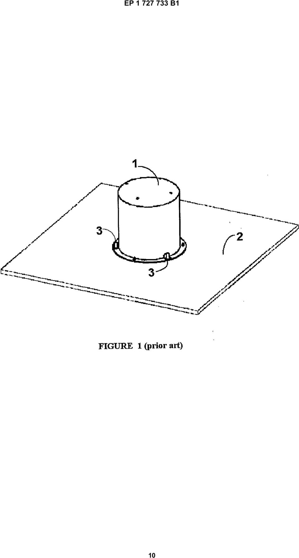
3 1 EP B1 2 Description BACKGROUND OF THE INVENTION Field of the Invention [0001] The present invention relates to the field of the mechanisms for deployment of space tethers from earth orbiting spacecraft or satellite carriers and in particular to the class of expendable tether mechanisms for passive on orbit deployment of end-masses tethered by a long space tether and that do not require to be retrieved. [0002] Tethers many kilometres in length, to be stored by winding up onto the present mechanism, may be either conductive, usually made of copper or aluminium, or nonconductive, such as those made of Kevlar, Spectra, glass fibre, quartz fibre, et c. depending on the space tether application. [0003] One of the most important issues for an application requiring a tether many kilometres in length is the on-orbit deployment (and retrieval) operation, since unless the orbiting tethered masses have a difference in orbiting altitude of some kilometres (measured along the local vertical direction), the connecting tether will not have sufficient tension or separating force (due to the difference of the gravity gradients associated with the two end-masses) to allow a passive tether deployment. This means that the tether passive deployment will only be possible if the friction force of the tether deployment (within the tether mechanism) is smaller than the tension force along the tether, due to the effect of the Earth gravitational field onto the tethered masses. [0004] Low friction for a tether deployment mechanism is therefore very important, in particular in order to allow a passive deployment and control for conductive or nonconductive space tether applications, such as electrodynamic propulsion for orbit raising or maintenance, deorbiting of a spacecraft at the end of its operational lifetime, and other non-conductive tether applications. [000] The field of application of the present invention is therefore the deployment mechanisms for space tethers, having a very low early deployment friction or resistance, in order to allow passive deployment of a tethered mass with only the application of an initial and rather small separation impulse provided by a spring separation mechanism or a similar space separation device. Description of the Prior Art [0006] Conductive tethers may be used to provide propulsion for orbital adjustment. It is a simple fact of physics that a current flowing through a conductor creates a magnetic field. If a satellite sends current generated by its solar arrays through a conductive tether, the direction of the current may be such as to generate a magnetic field in the opposite direction with respect to the Earth s magnetic field, with consequent magnetic "drag" which degrades the satellite orbit. If the satellite sends the current through the conductive tether in the opposite direction, it generates a magnetic field which works with the Earth s magnetic field, and the satellite orbit will rise. [0007] An important application for the type of passive deployer disclosed here is a Low Earth Orbit (LEO) satellite carrier or a launcher last stage equipped with a deorbiting device having several-kilometre long and conductive tether and a passive deployer of the type here described and illustrated in Figure 1 (reflecting the state of the art), with its protective cover 1 mounted on an exterior spacecraft panel 2 by means of three pyro-bolts 3. [0008] This de-orbiting device represents a state-ofthe-art electro-dynamic tether system for de-orbiting of small and medium size LEO satellites and upper stages of launchers. Analyses show that the use of tethers for orbital adjustment is far more efficient in terms of spacecraft mass requirements than the use of chemical thrusters, though the orbital changes are also slow. Current studies indicate that a 2-kilogram tether deployed by a 100-kilogram satellite in an 80-kilometre high orbit can bring the satellite back to Earth in three months. [0009] A reference to this type of space tether application is given by the following conference papers: 1. "EDOARD: A Tethered Device for Efficient Electro-dynamic De-Orbiting of LEO Spacecraft", presented at the Space Technologies & Applications International Forum (STAIF 2001), Conference on Innovative Transportation Systems, Albuquerque, NM, USA, February 11-1, 2001, by Licata R., Iess L., Bruno C., and Bussolino L. 2. "EDOARD: An Electro-dynamic Tether Device for Efficient Spacecraft De-Orbiting", presented at the 3rd European Conference on Space Debris, Vol.2, Darmstad, Germany, March 19-21, 2001 by Licata R., Iess L., Bruno C., Bussolino L., Anselmo L., Schirone L., and Somesi L. In these published papers, presented by the present inventor and other authors, only the electro-dynamic tether application for space has been described and illustrated. The tether deployment mechanism and method of tether deployment, which form the subject of the present patent application, have been neither published nor disclosed before. The inventor is also aware of the following space tether deployment mechanism concepts and associated publication references, which however have not the same or similar design nor do they present the same characteristics of the deployment mechanism and passive deployment method disclosed here. These other tether deployment mechanisms, for similar space applications, are described in the following conference papers or journal articles: 3. Caroll, J.A., "SEDS Deployer Design and Flight Performance", AIAA Paper , whose mechanism was used in the NASA Missions SEDS- 1 in 1993 and SEDS-2 in In SEDS-1, a 2- Kilogram mini-satellite was deployed down towards 3

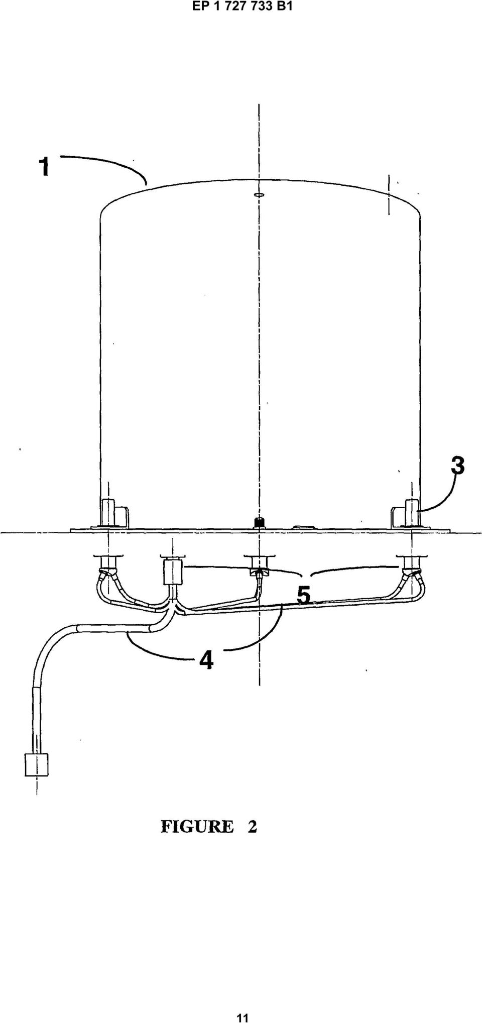
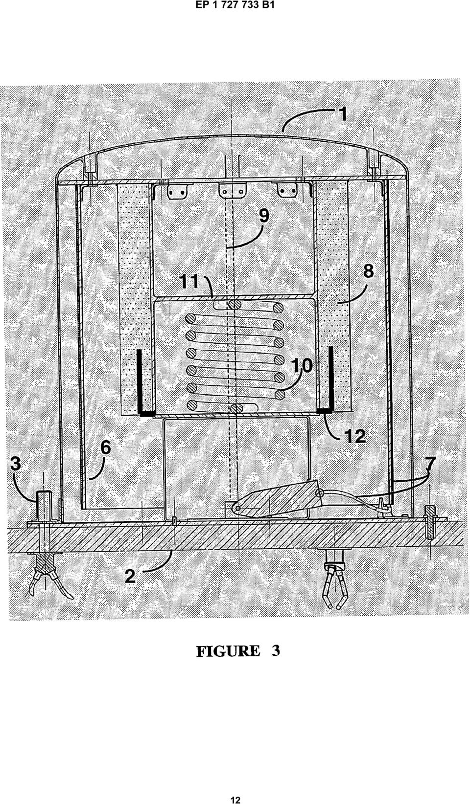
4 3 EP B1 4 the Earth. In 1994, the SEDS-2 experiment was performed with the same gear as SEDS-1, deploying a 20-Kilometre long tether. This document is considered to be the closest prior art document. 4. Koss, Stephen, "Tether Deployment Mechanism for the Advanced Tether Experiment (ATEX)", 7th European Space Mechanism and Tribology Symposium, p , European Space Agency, Noordwijk, The Netherlands, Licata, R. Gavira, J.M. Vysokanov, V. Bracciaferri, F., "SESDE - A First European Tether Experiment Mission", IAF-paper-98-A709, 49th International Astronautical Congress, Melbourne, Australia, 1998, in which the Small Expendable Spool Deployer (SESDE) concept is illustrated. 6. Nakamura, Yosuke, "Ground Experiments of a Micro Tether Reeling Mechanism", 23rd Intern. Symposium on Space Technology and Science, p , Matsue, Japan, May [00] None of these tether mechanisms has the characteristics or advantages of the mechanism and deployment method disclosed here, which allow the deployment of a full passive space tether from an orbiting spacecraft carrier, starting from the early stage of deployment, when gravity gradient tensions are still very low. [0011] The SEDS deployer design presented in Ref. 3. and being used in some space tether applications such as the SEDS missions, although it also implements tether storage or winding of the fixed spool type, similar to the one indicated in the present patent application, has in its outlet position a "barber pole" tether deployment brake, comprising a motor to rotate the "pole" onto which the tether is also wound on. The number of spirals on the "pole" of tether winding is controlled by the electrical motor and these make the tether deployment friction force used for its deployment brake varying. Consequently, even with its minimum winding of tether spirals onto the "barber pole" during early tether deployment phases, some high residual tether deployment friction force is always present in this type of mechanism, making very difficult if not impossible an early stage passive space tether deployment performance, as that which can be obtained by the mechanism disclosed in the present application. [0012] On the other hand, the ATEX mechanism indicated in Ref. 4. above, is not designed for cable tether but for tape tether, with tether reel and motor and hence very high deployment friction force and rather strong mechanical complications, not at all present in the mechanism described in the present application. [0013] The "Advanced Tether Experiment" (ATEX) in early 1999 was an element of a satellite named the "Space Test Experiment" (STEX), that tested a suite of new technologies for future NRO intelligence or support satellites. ATEX was intended to test a new tether scheme that was implemented as a tape over six-kilometre long and three-centimetre wide, with reinforcements consisting of fibre strands running down its length. However, the experiment was a complete failure, with only 22 meters of the tether being successfully deployed before STEX determined an out-of-bounds condition with tether deployment. STEX ejected the ATEX package to protect itself. The ATEX mechanism comprises a stepper motor driving a pair of pinch rollers pulling the tether off a level-wound reel. [0014] The SESDE mechanism design, illustrated and published in Ref., is also based on the tether winding of fixed spool type, but it does not possess the very low friction device, represented by the single tether layer cylindrical part for the early tether deployment, which is practically friction-less, the simple incorporated spring separation device and the passive tether deployment brake device of the tether mechanism disclosed in the present application. [001] Finally, the tether mechanism of Ref. 6 is not at all similar to the mechanism of the present patent application, since it implements a rotating reel for its tether storage and winding, with the consequence of requiring a reel motor and brake and other associated electromechanical complexities, in order to overcome high friction forces due to tether unwinding, reel shaft rotational friction force and torque, etc. OBJECTS OF THE INVENTION [0016] The main object of the present invention is to provide an expendable space tether deployment mechanism capable of passively deploying cable tethers made of various materials and long up to many kilometres (e.g Km) with very low friction force at the early stage of deployment, an incorporated impulsive separation device for the required tethered end-mass with minimum complexity. The tether structure (i.e. diameter, layers and materials) and length required by the specific application will determine the overall mechanism sizing, including fixed spool and external cylinder sizing, separation spring sizing et c. [0017] The tether deployment mechanism proposed in the present patent application may be mounted onto any external flat surface of a spacecraft, as shown in Figure 2, with external cover 1, mechanical interfaces, including some (usually three) pyro-bolts 3 to be actuated for an impulsive separation to initiate the tether deployment, data and power interfaces with the carrier spacecraft by the cables 4 and the connectors also shown in the same figure. [0018] The space tether mechanism disclosed here attains the object indicated above through the implementation of the following main mechanism features illustrated in the cross section drawing of Figure 3: a cylinder 6 onto which a first layer of some hundreds of meters of tether length 7 is wound-up, providing hence the very low friction or resistance force for the early part of the space tether deployment operation; 4

5 EP B1 6 a fixed cylindrical tether spool 8, representing the deployer-storing device for the remaining kilometres of tether length. Continuity of the tether winding (and deployment) from the first part on the mechanism external cylindrical surface 6 and its interior tether spool 8 is allowed by a longitudinal cut 9 made along the external cylinder length, having a width of only a few millimetres (depending upon the tether diameter size) but sufficient to allow the tether passage at the end of the first part of the deployment and the starting of the internal tether spool deployment; a spring separation mechanism, represented by the centrally mounted spring on the interior interface plane 11 and the (three) pyro-bolts 3, used for installing the deployer cover 1 onto the carrier satellite structure 2 and also for separating these deployer parts on orbit with a deployment time command sent through the carrier spacecraft; a passive tether spool deployment brake 12, able to passively start its activation during the last part of tether deployment. This is implemented in the tether spool winding by a device of daisy shape that opens up or deploys when freed by the space tether unwinding, as soon as it reaches the planned deployed tether length or tether spool level, as illustrated in the same Figure 3. [0019] A further object of the present invention is to provide a method for the passive deployment of a tether by means of the mechanism cited above. This method is described below and is also detailed in the characterising part of claim 3. DESCRIPTION OF THE PREFERRED EMBODIMENTS [0020] The mechanism described here may be fitted onto a satellite bus with minimum mass, complexity and cost, as it limits the number of tether deployment mechanism components to a minimum, while minimising the risk of failure. [0021] Minimum electrical and mechanical or structural interfaces are required, as also shown in Figures 2 and 4. [0022] In the mechanism described here, the impulse for the separation and starting of the on-orbit tether deployment is provided by a simple system illustrated in Figure 3, with a spring accommodated at the centre of the fixed tether spool 8 and attached to it by a mechanical interface plane 11. When the deployer cover 1 is freed by the simultaneous actuation of the (three) pyrobolts 3 through a suitable ground command, the central separation spring is freed at one end and hence imparts the planned impulse to the tethered deployer mass and transforms its stored energy in form of kinetic energy of the tethered masses. [0023] As shown in Figure 4, after the actuation of the pyro-bolts 3 and spring system, the first portion of tether 7, wound-up onto the outer mechanism cylinder , will start deploying the mechanism part with tether spool 8, the deployer cover 1 and the spring system will separate from the carrier spacecraft 2 onto which the deployer interface plane 13 and the electronics boxes, comprising the hollow cathode 14 and the controller 1, the tether attachment point with its three-axis magnetometer 16, together with data and power interfaces 17 will remain attached. [0024] Therefore during the on-ground preparation activity, the many-kilometre long conductive tether is hence wound-up firstly onto the inner cylindrical spool 8 and hence onto the outer cylinder 6 with nearly zero early tether deployment friction (having only one single layer of tether winding on the exterior cylinder 6) and thus providing a passive deployment after a small initial separation impulse. [002] After on-ground assembling of the tether mechanism, during installation activity on the carrier vehicle and ground and space transportation, the outer tether winding tension is kept by a simple V-shaped device 18, mounted on an interface plane 13 that is installed onto the carrier spacecraft by (usually) three bolts 19, as shown in Figure 4. [0026] Once the on-orbit deployment of the first part of tether length is completed, the tether will deploy passing through the cut 9 of the external cylinder illustrated in Figure 3, and then the fixed spool tether will start deploying with higher deployment friction or resistance with respect to the earlier part of the deployment. [0027] Depending on the tethered masses, the deployed tether length and also the initial separation rate and friction values, at some stage of the many-kilometre long deployment, when the differential gradient applied to the tethered masses in the earth gravitational field is sufficiently high, the tether deployment rate will start gradually increasing. Unless some higher deployment resistance or friction force is applied, the deployment rate could reach so high values as ten or more metres per second in case of very long deployments. In any case, before the end of the deployment, in order to limit the maximum value of deployment rate during operations and even decrease it in its last part of deployment, a braking device 12 has been introduced in the tether spool winding so that it is freed to deploy as a daisy and providing high friction, hence high tether deployment resistance, for the remaining part of the space tether to be deployed. Claims 1. A deployment mechanism for expendable space tether applications comprising essentially a fixed single-layer tether winding cylinder (6), a multiple-layer tether winding central spool (8), an initial separation impulse mechanism () for passive tether deployment, and a tether deployment brake (12) of daisylike shape; characterised in that
 pyro-bolts 3,")
6 7 EP B1 8 said mechanism accommodates a first portion of tether (7), many kilometres in length, wound up on said inner multi-layer spool (8), followed by a second portion of said tether (7), many hundred metres in length, wound up in a single layer on said outer cylinder (6); in order to allow the passage of the tether (7) both on ground, during the required tether winding and preparatory operations, and on-orbit, during the actual deployment by the unwinding of its two types of tether windings, a surface cut (9) of said outer cylinder (6) of sufficient width and along most of its length is provided such that once the continuous space tether is deployed on orbit, the unwinding tether will pass through said cylinder cut (9) and will continue to unwind from said multi-layer central spool (8) till the end of deployment; said initial separation impulse mechanism for passive tether deployment comprises a central sinusoidal spring (), mounted inside the core of said fixed multi-layer tether spool (8) and capable of storing the required energy for initial separation of the tethered masses; said separation spring () is kept in a compressed state, during ground operations and ground and space transportation and before on-orbit separation and deployment, by some, usually three, pyrobolts (3) mounted on the mechanism cover (1) and its interface plane with the external surface (2) of the carrier spacecraft; at separation time, on command coming from ground through the carrier spacecraft telemetry and telecommand on-board system, said pyro-bolts (3) are actuated, said central spring () is released and the whole deployment mechanism, with its cover (1), spring () and full tether windings, will separate about the orbit local vertical direction from said carrier spacecraft (2); and said passive tether deployment brake (12) of daisy-like shape and flexible material, incorporated within said centrally fixed multi-layer spool tether winding (8) and fixed on the spool central core mounting, will deploy on-orbit during tether deployment operation at the planned length of the deployed tether or distance of the tethered end-masses; the deployment of this device increases by the planned magnitude or amount the tether deployment friction resistance force, so that the decreasing of the tether deployment rate from the deployer mechanism is gradually provided and applied until the end of the deployment operation. 2. The deployment mechanism claimed in claim 1, further comprising a tether mechanism interface plane (13), to be bolted onto said external surface (2) of the carrier spacecraft, an external protective cover (1) bolted by said pyro-bolts (3) to said interface plane (2) with the carrier spacecraft, mountings of the carrier-end tether attachment (16), electronic boxes (17), data and power interface connectors (), and an outer tether winding V-shaped gripping or restraining device (18); characterised in that said tether mechanism interface plane (13) is bolted to an external surface (2) of said carrier spacecraft by substantially three simple bolts (19) and remains mounted onto the external surface of the carrier, with electronics and other components of the deployment device, after onorbit initial separation of the deployer mechanism and deployment operations of the tether and the tethered end-masses; in that said external protective cover (1) bounded by said pyrobolts (3) to the interface plane (13) with said carrier spacecraft is bolted as a single structure to said tether winding spool (8) structures with said spring separation device () incorporated; said cover (1) is also used as a protective shell, for the tether windings and all the other deployer mechanism components, mainly against potential micro-meteorite impacts and the material aging effects due to ultra-violet ray exposure or to exposure to other types of dangerous space radiation; said mountings of the attachment point of the tether end at the carrier spacecraft side, said electronics boxes (17) and said data and power interface connectors () of the tether application system, such as for the electro-dynamic tether propulsion application, and said V-shaped outer tether winding restraining or gripping device (18) are all mounted to be fixed and to remain on the mechanism interface plane, on the exterior of the carrier spacecraft until the end of the space tether application; the carrier spacecraft bound electronics components for the electro-dynamic tether application are represented by a hollow cathode (14), relays and current measurement and control electronics (1); and said V-shaped tether winding gripping device (18) is of elastic (beam) type and its mounting on the interface plane is in correspondence of said outer tether winding cylinder (6) end-border, so that the first few single layer tether winding spirals are gripped to the cylinder surface and the tether winding tension kept until on-orbit deployment separation action for which these tether winding spirals and cylinder are freed from said V-shaped restraining device (18). 3. A passive method for tether unwinding, using the mechanism claimed in claim 1, characterised in that said tether unwinding comprises the following steps: an impulse applied for separation from said spacecraft (2) performed by said spring (); tether 6
 and will continue to unwind from said")
7 9 EP B1 unwinding from said single-layer cylindrical outer spool (6), involving a first tether length of many hundred metres with tether deployment resistance or friction force of value nearly equal to zero; further tether unwinding from said multi-layer spool (8), located inside said outer single-layer spool (6) of the remaining portion of the many kilometres long tether; and tether deployment braking action resulting from a constant friction force applied by means of said brake (12), through which said tether (7) is made to pass. Patentansprüche 1. Ausbringmechanismus für Anwendungen von Einweg-Weltraumhalteseilen, welcher im Wesentlichen einen befestigten einschichtigen Halteseil-Wicklungszylinder (6), eine mittlere mehrschichtige Halteseil-Wicklungsrolle (8), einen anfänglichen Trennimpulsmechanismus () zum passiven Ausbringen des Halteseils und eine Halteseilausbringbremse (12) margaritenblütenartiger Form umfassen; dadurch gekennzeichnet, dass der Mechanismus einen viele Kilometer langen ersten Abschnitt des Halteseils (7) umfasst, der auf der inneren mehrschichtigen Rolle (8) aufgewickelt ist, gefolgt von einem viele hundert Meter langen zweiten Abschnitt des Halteseils (7), der in einer einzelnen Schicht auf dem äußeren Zylinder (6) aufgewickelt ist; um das Vorbeilaufen des Halteseils (7) sowohl auf dem Boden während der erforderlichen Halteseilaufwicklungs- und Vorbereitungsoperationen als auch im Weltraum während des tatsächlichen Ausbringens durch das Abwickeln seiner beiden Arten der Halteseilwicklungen zu ermöglichen, ein Oberflächenschnitt (9) in dem äußeren Zylinder (6) von ausreichender Breite und entlang dem größten Teil seiner Länge bereitgestellt wird, derart, dass, sobald das durchgehende Weltraum-Halteseil im Weltraum ausgebracht wird, das sich abwickelnde Halteseil durch den Zylinderschnitt (9) hindurch läuft und sich bis zum Ende des Ausbringens weiter von der mittleren mehrschichtigen Rolle (8) abwikkelt; der anfängliche Trennimpulsmechanismus zum passiven Ausbringen des Halteseils eine mittlere sinusförmige Feder () umfasst, welche innerhalb des Kerns der befestigten mehrschichtigen Halteseilrolle (8) angebracht ist und die für die anfängliche Trennung der gehaltenen Massen erforderliche Energie speichern kann; die Trennfeder () während der Bodenoperationen und während des Boden- und Weltraumtransports und vor der Trennung und dem Ausbringen im Weltraum durch einige, gewöhnlich drei, Pyroschrauben (3), die auf der Abdekkung (1) des Mechanismus und ihrer Grenzflächenebene mit der äußeren Fläche (2) des Träger-Raumfahrzeugs angebracht sind, in einem komprimierten Zustand gehalten wird; im Trennungszeitpunkt auf einen Befehl, der über die Telemetrie des Träger-Raumfahrzeugs und das ferngesteuerte Bordsystem vom Boden kommt, die Pyroschrauben (3) betätigt werden, die mittlere Feder () freigegeben wird und der gesamte Ausbringmechanismus mit seiner Abdeckung (1), seiner Feder () und seinen vollständigen Halteseilwicklungen sich in lokaler vertikaler Raumrichtung von dem Träger-Raumfahrzeug (2) trennt; und die Bremse (12) margaritenblütenartiger Form und flexiblen Materials für das passive Ausbringen des Halteseils, welche in die in der Mitte befestigte Mehrschichtrollenwicklung (8) des Halteseils eingebaut ist und auf der Befestigung des Zentralkerns der Rolle angebracht ist, während der Halteseil-Ausbringoperation im Weltraum bei der geplanten Länge des ausgebrachten Halteseils oder der geplanten Entfernung der gehaltenen Endmassen eingesetzt wird; der Einsatz dieser Vorrichtung die Reibungskraft beim Ausbringen des Halteseils um die geplante Größe oder Menge erhöht, so dass der Rückgang der Ausbringgeschwindigkeit des Halteseils aus dem Ausbringmechanismus bis zum Ende der Ausbringoperation allmählich bereitgestellt und angewendet wird. 2. Ausbringmechanismus nach Anspruch 1, welcher ferner eine Grenzflächenebene (13) des Halteseilmechanismus, welche auf die äußere Fläche (2) des Träger-Raumfahrzeugs zu schrauben ist, eine äußere Schutzabdeckung (1), welche durch die Pyroschrauben (3) an die Grenzflächenebene (2) mit dem Träger-Raumfahrzeug geschraubt ist, Befestigungen der Halteseilbefestigung (16) am Trägerende, Elektronikkästen (17), Daten- und Stromschnittstellenverbinder () und eine äußere V-förmige Klemm- oder Rückhaltevorrichtung (18) für die Halteseilwicklung umfasst; dadurch gekennzeichnet, dass die Grenzflächenebene (13) des Halteseilmechanismus im Wesentlichen durch drei einfache Schrauben (19) an eine äußere Fläche (2) des Träger- Raumfahrzeugs geschraubt ist und mit der Elektronik und anderen Komponenten der Ausbringvorrichtung nach einer anfänglichen Trennung des Ausbringmechanismus im Weltraum und Ausbringoperationen des Halteseils und der gehaltenen Endmassen auf der äußeren Fläche des Trägers befestigt bleibt; dass die äußere Schutzabdeckung (1), welche durch die Pyroschrauben an die Grenzflächenebene (13) mit dem Träger-Raumfahrzeug gebunden ist, als Einzelstruktur an die Strukturen der Halteseil-Wicklungsrolle (8) mit der eingebauten Feder- Trennvorrichtung () geschraubt ist; die Abdekkung (1) auch als Schutzhülle für die Halteseilwicklungen und alle anderen Komponenten des Ausbringmechanismus verwendet wird, hauptsächlich 7
, eine mittlere mehrschichtige")
8 11 EP B1 12 gegen mögliche Mikrometeoriteneinschläge und die Materialalterungseffekte aufgrund von ultravioletter Bestrahlung oder Bestrahlung mit anderen Arten gefährlicher Weltraumstrahlung; die Befestigungen des Befestigungspunktes des Halteseilendes auf der Seite des Träger-Raumfahrzeugs, die Elektronikkästen (17) und die Daten- und Stromschnittstellenverbinder () des Halteseil-Anwendungssystems, z.b. für die elektrodynamische Halteseil-Vortriebsanwendung, und die äußere V- förmige Rückhalte- oder Klemmvorrichtung (18) für die Halteseilwicklung alle so angebracht sind, dass sie befestigt sind und bis zum Ende der Halteseilanwendung im Weltraum auf der Grenzflächenebene des Mechanismus auf der Außenseite des Träger- Raumfahrzeugs bleiben; die an das Träger-Raumfahrzeug gebundenen Elektronikkomponenten für die elektrodynamische Halteseilanwendung durch eine Hohlkathode (14), Relais und die Strommessund -regelelektronik (1) dargestellt werden; und die V-förmige Klemmvorrichtung (18) für die Halteseilwicklung elastischer (Stangen-)Art ist und ihre Befestigung auf der Grenzflächenebene mit der Endbegrenzung des äußeren Halteseil-Wicklungszylinders (6) in Übereinstimmung steht, so dass die ersten wenigen einschichtigen Halteseilwindungen an die Zylinderoberfläche geklemmt werden und die Halteseil-Wicklungsspannung bis zum Weltraumausbring-Trennvorgang bewahrt wird, für welchen diese Halteseilwindungen und der Zylinder von der V-förmigen Rückhaltevorrichtung (18) befreit werden. 3. Passives Verfahren zur Halteseilabwicklung unter Anwendung des Mechanismus nach Anspruch 1, dadurch gekennzeichnet, dass die Halteseilabwicklung die folgenden Schritte umfasst: einen für die Trennung von dem Raumfahrzeug (2) angewendeten Impuls, der von der Feder () ausgeht; Abwickeln des Halteseils von der einschichtigen zylindrischen äußeren Rolle (6) unter Beteiligung ersten Halteseillänge von vielen hundert Metern mit einer Widerstands- oder Reibungskraft für das Ausbringen des Halteseils, die einen Wert von nahezu Null aufweist; weiteres Abwickeln des verbleibenden Abschnitts des viele Kilometer langen Halteseils von der mehrschichtigen Rolle (8), welche innerhalb der äußeren einschichtigen Rolle (6) angeordnet ist; und einen Bremsvorgang für das Ausbringen des Halteseils, welcher aus einer konstanten Reibungskraft resultiert, die mittels der Bremse (12) angewendet wird, durch welche hindurch das Halteseil (7) geführt wird. Revendications Mécanisme de déploiement pour applications de câble spatial extensible comprenant essentiellement un cylindre d enroulement de câble monocouche fixe (6), un mécanisme d impulsion de séparation initiale () pour le déploiement de câble passif, et un frein de déploiement de câble (12) en forme de marguerite ; caractérisé en ce que ledit mécanisme accueille une première portion de câble (7), de nombreux kilomètres de longueur, enroulée sur ladite bobine multicouche interne (8), suivie d une seconde portion dudit câble (7), de nombreuses centaines de mètres de longueur, enroulée dans une seule couche sur ledit cylindre externe (6) ; pour permettre le passage du câble (7) à la fois au sol, pendant les opérations requises d enroulement et de préparation de câble, et en orbite, pendant le déploiement réel par le déroulement de ses deux types d enroulement de câble, une coupure de surface (9) dudit cylindre externe (6) de largeur suffisante et le long de la plupart de sa longueur est fournie, de sorte que, une fois que le câble spatial continu est déployé en orbite, le câble se déroulant traverse ladite coupure de cylindre (9) et continue à se dérouler de ladite bobine centrale multicouche (8) jusqu à la fin du déploiement ; ledit mécanisme d impulsion de séparation initiale pour le déploiement de câble passif comprend un ressort sinusoïdal central (), monté à l intérieur du noyau de ladite bobine de câble multicouche fixe (8) et capable de stocker l énergie requise pour la séparation initiale des masses câblées ; ledit ressort de séparation () est maintenu dans un état comprimé, pendant les opérations terrestres et le transport terrestre et spatial et avant la séparation et le déploiement en orbite, par certains, généralement trois, pyro-boulons (3) montés sur le capot de mécanisme (1) et son plan d interface avec la surface externe (2) du vaisseau spatial porteur ; au moment de la séparation, sur commande du sol à travers le système embarqué de télémétrie et de télécommande du vaisseau spatial porteur, lesdits pyro-boulons (3) sont actionnés, ledit ressort central () est relâché et tout le mécanisme de déploiement, avec son capot (1), le ressort () et les bobinages de câble complets, se séparent autour de la direction verticale locale d orbite dudit vaisseau spatial porteur (2) ; et ledit frein de déploiement de câble passif (12) en forme de marguerite et de matériau flexible, incorporé au dit bobinage de câble de bobine multicouche fixe centralement (8) et fixé sur le montant de noyau central de bobine, se déploie en orbite pendant l opération de déploiement de câble à la longueur planifiée du câble déployé ou à la distance des masses d extrémité câblées ; le déploiement de ce dispositif augmente de la grandeur planifiée ou de la quantité de la force de résistance de frottement de déploiement de câble, de sorte que la réduction du taux de déploiement de câble du mécanisme de déploiement est progressivement fournie et appliquée jus- 8
 für die Halteseilwicklung alle so angebracht sind, dass sie befestigt sind und")
9 13 EP B1 14 qu à la fin de l opération de déploiement. 2. Mécanisme de déploiement selon la revendication 1, comprenant en outre un plan d interface de mécanisme de câble (13), à boulonner sur ladite surface externe (2) du vaisseau spatial porteur, un capot de protection externe (1) boulonné par lesdits pyro-boulons (3) sur ledit plan d interface (2) avec le vaisseau spatial porteur, des montants de la fixation de câble d extrémité de porteur (16), des boîtiers électroniques (17), des connecteurs d interface de données et d alimentation électrique (), et un dispositif d accrochage ou de retenue en forme de V de bobinage de câble extérieur (18) ; caractérisé en ce que : ledit plan d interface de mécanisme de câble (13) est boulonné sur une surface externe (2) dudit vaisseau spatial porteur par sensiblement trois boulons simples (19) et reste monté sur la surface externe du porteur, avec des composants électroniques et d autres composants du dispositif de déploiement, après la séparation initiale en orbite du mécanisme de déploiement et les opérations de déploiement du câble et des masses d extrémité câblées ; en ce que ledit capot de protection externe (1) lié par lesdits pyro-boulons (3) au plan d interface (13) avec ledit vaisseau spatial porteur est boulonné en tant que structure unique sur lesdites structures de bobine de bobinage de câble (8) avec ledit dispositif de séparation de ressort () incorporé ; ledit capot (1) est également utilisé en tant que coque de protection, pour les bobinages de câble et tous les autres composants de mécanisme de déploiement, principalement contre les impacts potentiels de micrométéorites et les effets du vieillissement de matériau sous l effet de l exposition aux rayons ultraviolets ou de l exposition à d autres types de rayonnement spatial dangereux ; lesdits montants du point d attache de l extrémité de câble sur le côté du vaisseau spatial porteur, lesdits boîtiers électroniques (17) et lesdits connecteurs d interface de données et d alimentation électrique () du système d application de câble, comme pour l application de propulsion de câble électrodynamique, et ledit dispositif d accrochage ou de retenue de bobinage de câble extérieur en forme de V (18) sont tous montés pour être fixés et pour rester sur le plan d interface de mécanisme, à l extérieur du vaisseau spatial porteur jusqu à la fin de l application de câble spatial ; les composants électroniques liés du vaisseau spatial porteur pour l application de câble électrodynamique sont représentés par une cathode creuse (14), des relais et des composants électroniques de mesure et de régulation de courant (1) ; et le dispositif d accrochage de bobinage de câble en forme de V (18) est d un type élastique (poutre) et son montage sur le plan d interface est en correspondance avec la frontière d extrémité dudit cylindre de bobinage de câble extérieur (6), de sorte que les premières spirales de bobinage de câble monocouche sont accrochées à la surface du cylindre et la tension de bobinage de câble est maintenue jusqu à l action de séparation de déploiement en orbite pour laquelle ces spirales de bobinage de câble et le cylindre sont libérés dudit dispositif de retenue en forme de V (18). 3. Procédé passif de déroulement de câble, utilisant le mécanisme selon la revendication 1, caractérisé en ce que ledit déroulement de câble comprend les étapes suivantes : une impulsion appliquée pour la séparation dudit vaisseau spatial (2) effectuée par ledit ressort () ; le déroulement de câble de ladite bobine extérieure cylindrique monocouche (6), impliquant une première longueur de câble de nombreuses centaines de mètres avec une force de résistance ou de frottement de déploiement de câble d une valeur presque égale à zéro ; la poursuite du déroulement de câble de ladite bobine multicouche (8) située à l intérieur de ladite bobine monocouche externe (6) de la portion restante de nombreux kilomètres de longueur de câble ; et l action de freinage de déploiement de câble découlant d une force de frottement constante appliquée au moyen dudit frein (12), à travers lequel ledit câble (7) est amené à passer. 9
, des connecteurs d interface de données et d alimentation électrique (), et un dispositif d accrochage ou de retenue en forme de V de bobinage de câble extérieur (18) ;")
10 EP B1
11 EP B1 11
12 EP B1 12
13 EP B1 13

14 EP B1 REFERENCES CITED IN THE DESCRIPTION This list of references cited by the applicant is for the reader s convenience only. It does not form part of the European patent document. Even though great care has been taken in compiling the references, errors or omissions cannot be excluded and the EPO disclaims all liability in this regard. Non-patent literature cited in the description LICATA R. ; IESS L. ; BRUNO C. ; BUSSOLINO L. EDOARD: A Tethered Device for Efficient Electro-dynamic De-Orbiting of LEO Spacecraft. Space Technologies & Applications International Forum (STAIF 2001), Conference on Innovative Transportation Systems, 11 February 2001 [0009] LICATA R. ; IESS L. ; BRUNO C. ; BUSSOLINO L. ; ANSELMO L. ; SCHIRONE L. ; SOMESI L. EDOARD: An Electro-dynamic Tether Device for Efficient Spacecraft De-Orbiting. the 3rd European Conference on Space Debris, 19 March 2001, vol. 2 [0009] CAROLL, J.A. SEDS Deployer Design and Flight Performance. AIAA Paper, 1993, [0009] KOSS ; STEPHEN. Tether Deployment Mechanism for the Advanced Tether Experiment (ATEX. 7th European Space Mechanism and Tribology Symposium, 1997, [0009] LICATA, R. GAVIRA ; J.M. VYSOKANOV ; V. BRACCIAFERRI, F. SESDE - A First European Tether Experiment Mission. 49th International Astronautical Congress, 1998, 98-A709 [0009] NAKAMURA ; YOSUKE. Ground Experiments of a Micro Tether Reeling Mechanism. 23rd Intern. Symposium on Space Technology and Science, May 2002, [0009] 14
, Conference on Innovative Transportation Systems, 11 February 2001 [0009] LICATA R. ; IESS L. ; BRUNO C. ; BUSSOLINO L. ; ANSELMO L.")
CABLE TESTER. Manual DN-14003
 CABLE TESTER Manual DN-14003 Note: Please read and learn safety instructions before use or maintain the equipment This cable tester can t test any electrified product. 9V reduplicated battery is used in
Snap-in switch for switches PSE, MSM and MCS 30
 Product manual Snap-in switch for switches PSE, MSM and MCS 30 CONTENTS 1. PRODUCT DESCRIPTION 2. DATA AND DIMENSIONAL DRAWINGS 2.1. Technical Data 2.2. Dimensions of PSE with a Mounting Diameter 19 mm
11 EN 81-70 Page 1 of 2 Standard: INTERPRETATION RELATED TO. Clause(s): 5.4.2.3
: 5.4.2.3") CEN RELATED TO 11 Page 1 of 2 Standard: Edition: 2003 Clause(s): 5.4.2.3 Valid from: 15/09/2010 Date of modification: Key-word(s): Car operating panel, Two entrance lift Replacing interpretation No.: QUESTION
CEN RELATED TO 11 Page 1 of 2 Standard: Edition: 2003 Clause(s): 5.4.2.3 Valid from: 15/09/2010 Date of modification: Key-word(s): Car operating panel, Two entrance lift Replacing interpretation No.: QUESTION
Dolby International AB
 February 1, 2019 MVC Attachment 1 Page 1 of 25 Dolby International AB AT-E 565534 AU 2008241568 AU 2012238296 AU 2012238297 BE 2,209,319 CN 200710127106.8 DE 60 2004 038 472.0 ES 2,390,596 FI 2,209,319
Test Report. Test of resitance to inertia effects of Zirkona Backwall. Sled Test (Frontal Impact) 20 g / 30 ms
 20 g / 30 ms") Test Report Test of resitance to inertia effects of Zirkona Backwall Sled Test (Frontal Impact) 20 g / 30 ms This report serves solely as a documentation of test results. 93XS0002-00_TdC.doc Page 1 1.
Test Report Test of resitance to inertia effects of Zirkona Backwall Sled Test (Frontal Impact) 20 g / 30 ms This report serves solely as a documentation of test results. 93XS0002-00_TdC.doc Page 1 1.
Evidence of Performance
 Air permeability, Watertightness, Resistance to wind load, Operating forces, Mechanical properties, Mechanical durability, Impact resistance Expert Statement No. 15-002226-PR01 (02) Product Designation
p^db=`oj===pìééçêíáåñçêã~íáçå=
 p^db=`oj===pìééçêíáåñçêã~íáçå= Error: "Could not connect to the SQL Server Instance" or "Failed to open a connection to the database." When you attempt to launch ACT! by Sage or ACT by Sage Premium for
Newest Generation of the BS2 Corrosion/Warning and Measurement System
 Newest Generation of the BS2 Corrosion/Warning and Measurement System BS2 System Description: BS2 CorroDec 2G is a cable and energyless system module range for detecting corrosion, humidity and prevailing
https://portal.microsoftonline.com
 Sie haben nun Office über Office365 bezogen. Ihr Account wird in Kürze in dem Office365 Portal angelegt. Anschließend können Sie, wie unten beschrieben, die Software beziehen. Congratulations, you have
Formatting the TrekStor i.beat run
 DE EN Formatting the TrekStor i.beat run Formatierung des TrekStor i.beat run a Beim Formatieren werden ALLE Daten auf dem MP3-Player gelöscht. In diesem Abschnitt wird Ihnen erläutert, wie Sie Ihren MP3-Player
Release Notes BRICKware 7.5.4. Copyright 23. March 2010 Funkwerk Enterprise Communications GmbH Version 1.0
 Release Notes BRICKware 7.5.4 Copyright 23. March 2010 Funkwerk Enterprise Communications GmbH Version 1.0 Purpose This document describes new features, changes, and solved problems of BRICKware 7.5.4.
Daimler. Patent Portfolio PRE-SAFE.
 Daimler. Patent Portfolio PRE-SAFE. Licensing Patent Portfolio PRE-SAFE Patent Portfolio PRE-SAFE Potentially hazardous driving situations such as skidding, emergency brakings or sudden obstacle avoidance
KURZANLEITUNG. Firmware-Upgrade: Wie geht das eigentlich?
 KURZANLEITUNG Firmware-Upgrade: Wie geht das eigentlich? Die Firmware ist eine Software, die auf der IP-Kamera installiert ist und alle Funktionen des Gerätes steuert. Nach dem Firmware-Update stehen Ihnen
Word-CRM-Upload-Button. User manual
 Word-CRM-Upload-Button User manual Word-CRM-Upload for MS CRM 2011 Content 1. Preface... 3 2. Installation... 4 2.1. Requirements... 4 2.1.1. Clients... 4 2.2. Installation guidelines... 5 2.2.1. Client...
miditech 4merge 4-fach MIDI Merger mit :
 miditech 4merge 4-fach MIDI Merger mit : 4 x MIDI Input Port, 4 LEDs für MIDI In Signale 1 x MIDI Output Port MIDI USB Port, auch für USB Power Adapter Power LED und LOGO LEDs Hochwertiges Aluminium Gehäuse
Kuhnke Technical Data. Contact Details
 Kuhnke Technical Data The following page(s) are extracted from multi-page Kuhnke product catalogues or CDROMs and any page number shown is relevant to the original document. The PDF sheets here may have
Registration of residence at Citizens Office (Bürgerbüro)
") Registration of residence at Citizens Office (Bürgerbüro) Opening times in the Citizens Office (Bürgerbüro): Monday to Friday 08.30 am 12.30 pm Thursday 14.00 pm 17.00 pm or by appointment via the Citizens
Registration of residence at Citizens Office (Bürgerbüro) Opening times in the Citizens Office (Bürgerbüro): Monday to Friday 08.30 am 12.30 pm Thursday 14.00 pm 17.00 pm or by appointment via the Citizens
(51) Int Cl. 7 : G09F 21/12. (72) Erfinder: Schimanz, Gerhard
 Int Cl. 7 : G09F 21/12. (72) Erfinder: Schimanz, Gerhard") (19) Europäisches Patentamt European Patent Office Office européen des brevets *EP001411488A1* (11) EP 1 411 488 A1 (12) EUROPÄISCHE PATENTANMELDUNG (43) Veröffentlichungstag: 21.04.2004 Patentblatt 2004/17
(19) Europäisches Patentamt European Patent Office Office européen des brevets *EP001411488A1* (11) EP 1 411 488 A1 (12) EUROPÄISCHE PATENTANMELDUNG (43) Veröffentlichungstag: 21.04.2004 Patentblatt 2004/17
Electrical tests on Bosch unit injectors
 Valid for Bosch unit injectors with order numbers 0 414 700 / 0 414 701 / 0 414 702 Parts Kit Magnet*: - F00H.N37.925 - F00H.N37.933 - F00H.N37.934 * For allocation to the 10-place Bosch order number,
(51) Int Cl. 7 : G06K 7/00, G06K 13/08. (72) Erfinder: Baitz, Günter 13629 Berlin (DE) Kamin, Hartmut 10585 Berlin (DE)
 Int Cl. 7 : G06K 7/00, G06K 13/08. (72) Erfinder: Baitz, Günter 13629 Berlin (DE) Kamin, Hartmut 10585 Berlin (DE)") (19) Europäisches Patentamt European Patent Office Office européen des brevets *EP001347405A1* (11) EP 1 347 405 A1 (12) EUROPÄISCHE PATENTANMELDUNG (43) Veröffentlichungstag: 24.09.2003 Patentblatt 2003/39
(19) Europäisches Patentamt European Patent Office Office européen des brevets *EP001347405A1* (11) EP 1 347 405 A1 (12) EUROPÄISCHE PATENTANMELDUNG (43) Veröffentlichungstag: 24.09.2003 Patentblatt 2003/39
IP X4 MOA/SL/FL IP44, CH IP24. Montage-Anleitung Instructions de montage Assembling instructions. 225 cm. 60 cm 0
 MOA/SL/FL IP44, CH IP4 Arbeiten an den elektrischen Anlagen dürfen nur von autorisierten Fachleuten nach den örtlichen Vorschriften ausgeführt werden. Für nicht fachgerechte Installation wird jegliche
Where are we now? The administration building M 3. Voransicht
 Let me show you around 9 von 26 Where are we now? The administration building M 3 12 von 26 Let me show you around Presenting your company 2 I M 5 Prepositions of place and movement There are many prepositions
p^db=`oj===pìééçêíáåñçêã~íáçå=
 p^db=`oj===pìééçêíáåñçêã~íáçå= How to Disable User Account Control (UAC) in Windows Vista You are attempting to install or uninstall ACT! when Windows does not allow you access to needed files or folders.
UWC 8801 / 8802 / 8803
 Wandbedieneinheit Wall Panel UWC 8801 / 8802 / 8803 Bedienungsanleitung User Manual BDA V130601DE UWC 8801 Wandbedieneinheit Anschluss Vor dem Anschluss ist der UMM 8800 unbedingt auszuschalten. Die Übertragung
2 IP X4 WLS/FL IP24. Montage-Anleitung Instructions de montage Assembling instructions. 225 cm. 60 cm 0
 WLS/FL IP Arbeiten an den elektrischen Anlagen dürfen nur von autorisierten Fachleuten nach den örtlichen Vorschriften ausgeführt werden. Für nicht fachgerechte Installation wird jegliche Haftung abgelehnt.
11 kw** E82MV222_4B kw**
 EDK82ZWKN4 00459189 10/02 Netzschleifklemme Typ E82ZWKN4 Diese Anleitung enthält wichtige Hinweise für den Einsatz der Netzschleifklemme E82ZWKN4 und beschreibt deren Montage. ist nur gültig - für Netzschleifklemmen
*EP001363019A2* EP 1 363 019 A2 (19) (11) EP 1 363 019 A2 (12) EUROPÄISCHE PATENTANMELDUNG. (43) Veröffentlichungstag: 19.11.2003 Patentblatt 2003/47
 (11) EP 1 363 019 A2 (12) EUROPÄISCHE PATENTANMELDUNG. (43) Veröffentlichungstag: 19.11.2003 Patentblatt 2003/47") (19) Europäisches Patentamt European Patent Office Office européen des brevets *EP001363019A2* (11) EP 1 363 019 A2 (12) EUROPÄISCHE PATENTANMELDUNG (43) Veröffentlichungstag: 19.11.2003 Patentblatt 2003/47
(19) Europäisches Patentamt European Patent Office Office européen des brevets *EP001363019A2* (11) EP 1 363 019 A2 (12) EUROPÄISCHE PATENTANMELDUNG (43) Veröffentlichungstag: 19.11.2003 Patentblatt 2003/47
(51) Int Cl.: B23K 26/28 (2014.01) B23K 26/32 (2014.01) B23K 26/30 (2014.01) B23K 33/00 (2006.01)
 Int Cl.: B23K 26/28 (2014.01) B23K 26/32 (2014.01) B23K 26/30 (2014.01) B23K 33/00 (2006.01)") (19) TEPZZ 87_Z ZA_T (11) EP 2 871 0 A1 (12) EUROPÄISCHE PATENTANMELDUNG (43) Veröffentlichungstag: 13.0.1 Patentblatt 1/ (21) Anmeldenummer: 13192326.0 (1) Int Cl.: B23K 26/28 (14.01) B23K 26/32 (14.01)
(19) TEPZZ 87_Z ZA_T (11) EP 2 871 0 A1 (12) EUROPÄISCHE PATENTANMELDUNG (43) Veröffentlichungstag: 13.0.1 Patentblatt 1/ (21) Anmeldenummer: 13192326.0 (1) Int Cl.: B23K 26/28 (14.01) B23K 26/32 (14.01)
USBASIC SAFETY IN NUMBERS
 USBASIC SAFETY IN NUMBERS #1.Current Normalisation Ropes Courses and Ropes Course Elements can conform to one or more of the following European Norms: -EN 362 Carabiner Norm -EN 795B Connector Norm -EN
Mock Exam Behavioral Finance
 Mock Exam Behavioral Finance For the following 4 questions you have 60 minutes. You may receive up to 60 points, i.e. on average you should spend about 1 minute per point. Please note: You may use a pocket
1. General information... 2 2. Login... 2 3. Home... 3 4. Current applications... 3
 User Manual for Marketing Authorisation and Lifecycle Management of Medicines Inhalt: User Manual for Marketing Authorisation and Lifecycle Management of Medicines... 1 1. General information... 2 2. Login...
Kuhnke Technical Data. Contact Details
 Kuhnke Technical Data The following page(s) are extracted from multi-page Kuhnke product catalogues or CDROMs and any page number shown is relevant to the original document. The PDF sheets here may have
a) Name and draw three typical input signals used in control technique.
 Name and draw three typical input signals used in control technique.") 12 minutes Page 1 LAST NAME FIRST NAME MATRIKEL-NO. Problem 1 (2 points each) a) Name and draw three typical input signals used in control technique. b) What is a weight function? c) Define the eigen value
12 minutes Page 1 LAST NAME FIRST NAME MATRIKEL-NO. Problem 1 (2 points each) a) Name and draw three typical input signals used in control technique. b) What is a weight function? c) Define the eigen value
Pneu. Linearantriebe mit externer Gleitführung Baureihe PLS
 Pneu. Linearantriebe mit externer Gleitführung Baureihe PLS Linearführung mit externer Gleitführung im Profil Linear guide with external gliding carriage on the profil Typ PLS/...zum Anbau an Linearzylinder
Overview thermostat/ temperature controller
 Thermostat TR-238 The Thermostat TR-238 is a electronic two-level controller for controlling of and in climate control units and vehicles. Voltage range (12V): Voltage range (24V): Control range: Hystereses:
Erste Glasbläserbrille, die als Arbeitsschutzbrille. The first glassblower s glasses which can be referred to as safety glasses.
 Kat.-Nr.: 114/elegant-UV-Protect Erste Glasbläserbrille, die als Arbeitsschutzbrille bezeichnet werden kann. Arbeitsschutzbrille für Glasbläser nach DIN EN 166, 177:2002 Anhang II der PSA-Richtlinie 89/686/EWG
Datasheet. Page 1 of 7
 Features 20 Encoder Positions 4-way Joystick LED-Illumination high quality signal processing Benefits Tactile multi purpose application premium design Hall Effect technology Applications Multiple switch
Circular Knitting Machine
 MOD. RR3-Z-R -1s-10 MOD. RR3-Z-R -109-10s MOD. RR3-Z-R J-109-4s/8s MOD. RR3-Z-R Machine Specifications mit stehendem Schlossmantel und rotierendem Zylinder Einsatzgebiete: Diese Maschine wird zur Herstellung
Hazards and measures against hazards by implementation of safe pneumatic circuits
 Application of EN ISO 13849-1 in electro-pneumatic control systems Hazards and measures against hazards by implementation of safe pneumatic circuits These examples of switching circuits are offered free
EEX Kundeninformation 2007-09-05
 EEX Eurex Release 10.0: Dokumentation Windows Server 2003 auf Workstations; Windows Server 2003 Service Pack 2: Information bezüglich Support Sehr geehrte Handelsteilnehmer, Im Rahmen von Eurex Release
EG-Zertifikat. wurde das Teilsystem (genauer beschrieben im Anhang) the following subsystem (as detailed in the attached annex)
 the following subsystem (as detailed in the attached annex)") _. _ NOTIFIED BODY INTEROPERABILITY EG-Zertifikat EC Certificate EG-Baumusterprufbescheinigung EC Type Examination Certificate Zertifikat-Nummer/ certificate Number: 0893/1/SB/12/RST/DE EN/2201 GemaR,
_. _ NOTIFIED BODY INTEROPERABILITY EG-Zertifikat EC Certificate EG-Baumusterprufbescheinigung EC Type Examination Certificate Zertifikat-Nummer/ certificate Number: 0893/1/SB/12/RST/DE EN/2201 GemaR,
Schalten einer kapazitiven Last mit einem Transistor
 . Schalten einer kapazitiven Last mit einem Transistor In allgemeinen technischen Anwendungen ist das Schalten einer kapazitiven Last eher von untergeordneter Bedeutung. In Rechnersystemen (Computernetzwerken)
ATEX-Check list. Compiled by: Date: Signature: Acceptable practice at the determination of flash point: Closed cup according to ISO 2719
 Fire and explosion hazard ATEX 137 1999/92/EG und ATEX 95 2014/34/EU Danger assessment and determination of explosion protection zone for the test space as well as the installation site ATEX-Check list
Magic Figures. We note that in the example magic square the numbers 1 9 are used. All three rows (columns) have equal sum, called the magic number.
 have equal sum, called the magic number.") Magic Figures Introduction: This lesson builds on ideas from Magic Squares. Students are introduced to a wider collection of Magic Figures and consider constraints on the Magic Number associated with such
Magic Figures Introduction: This lesson builds on ideas from Magic Squares. Students are introduced to a wider collection of Magic Figures and consider constraints on the Magic Number associated with such
Kurzanleitung um Transponder mit einem scemtec TT Reader und der Software UniDemo zu lesen
 Kurzanleitung um Transponder mit einem scemtec TT Reader und der Software UniDemo zu lesen QuickStart Guide to read a transponder with a scemtec TT reader and software UniDemo Voraussetzung: - PC mit der
Die Bedeutung neurowissenschaftlicher Erkenntnisse für die Werbung (German Edition)
") Die Bedeutung neurowissenschaftlicher Erkenntnisse für die Werbung (German Edition) Lisa Johann Click here if your download doesn"t start automatically Download and Read Free Online Die Bedeutung neurowissenschaftlicher
Die Bedeutung neurowissenschaftlicher Erkenntnisse für die Werbung (German Edition) Lisa Johann Click here if your download doesn"t start automatically Download and Read Free Online Die Bedeutung neurowissenschaftlicher
*EP001201606A1* EP 1 201 606 A1 (19) (11) EP 1 201 606 A1 (12) EUROPÄISCHE PATENTANMELDUNG. (43) Veröffentlichungstag: 02.05.2002 Patentblatt 2002/18
 (11) EP 1 201 606 A1 (12) EUROPÄISCHE PATENTANMELDUNG. (43) Veröffentlichungstag: 02.05.2002 Patentblatt 2002/18") (19) Europäisches Patentamt European Patent Office Office européen des brevets *EP001201606A1* (11) EP 1 201 606 A1 (12) EUROPÄISCHE PATENTANMELDUNG (43) Veröffentlichungstag: 02.05.2002 Patentblatt 2002/18
(19) Europäisches Patentamt European Patent Office Office européen des brevets *EP001201606A1* (11) EP 1 201 606 A1 (12) EUROPÄISCHE PATENTANMELDUNG (43) Veröffentlichungstag: 02.05.2002 Patentblatt 2002/18
PROFIBUS-DP Repeater 1 to 1 and 1 to 5 with optional level converter module
 LSS PROFIBUS-DP Repeater 1 to 1 and 1 to 5 with optional level converter module The LSS PROFIBUS-DP repeaters 1 to 1 and 1 to 5 are used for coupling up to six PROFIBUS bus segments in RS 485 bus technology.
Rev. Proc Information
 Rev. Proc. 2006-32 Information 2006, CPAs 1 Table 1-Total loss of the home Table 2- Near total loss is water to the roofline. Completely gut the home from floor to rafters - wiring, plumbing, electrical
Wissenschaftliche Dienste. Sachstand. Payment of value added tax (VAT) (EZPWD-Anfrage ) 2016 Deutscher Bundestag WD /16
 (EZPWD-Anfrage ) 2016 Deutscher Bundestag WD /16") Payment of value added tax (VAT) (EZPWD-Anfrage ) 2016 Deutscher Bundestag Seite 2 Payment of value added tax (VAT) (EZPWD-Anfrage ) Aktenzeichen: Abschluss der Arbeit: 07.04.2016 Fachbereich: WD 4: Haushalt
Payment of value added tax (VAT) (EZPWD-Anfrage ) 2016 Deutscher Bundestag Seite 2 Payment of value added tax (VAT) (EZPWD-Anfrage ) Aktenzeichen: Abschluss der Arbeit: 07.04.2016 Fachbereich: WD 4: Haushalt
Electrical testing of Bosch common rail piezo injectors
 Applies to generation CRI 3: Bosch 10-position order number 0 445 115 = CRI 3-16 (CRI 3.0) 1600 bar 0 445 116 = CRI 3-18 (CRI 3.2) 1800 bar 0 445 117 = CRI 3-20 (CRI 3.3) 2000 bar Tools required: Hybrid
H o c h s c h u l e D e g g e n d o r f H o c h s c h u l e f ü r a n g e w a n d t e W i s s e n s c h a f t e n
 Time Aware Shaper Christian Boiger christian.boiger@hdu-deggendorf.de IEEE 802 Plenary September 2012 Santa Cruz, California D E G G E N D O R F U N I V E R S I T Y O F A P P L I E D S C I E N C E S Time
DIBELS TM. German Translations of Administration Directions
 DIBELS TM German Translations of Administration Directions Note: These translations can be used with students having limited English proficiency and who would be able to understand the DIBELS tasks better
Titelbild1 ANSYS. Customer Portal LogIn
 Titelbild1 ANSYS Customer Portal LogIn 1 Neuanmeldung Neuanmeldung: Bitte Not yet a member anklicken Adressen-Check Adressdaten eintragen Customer No. ist hier bereits erforderlich HERE - Button Hier nochmal
NEWSLETTER. FileDirector Version 2.5 Novelties. Filing system designer. Filing system in WinClient
 Filing system designer FileDirector Version 2.5 Novelties FileDirector offers an easy way to design the filing system in WinClient. The filing system provides an Explorer-like structure in WinClient. The
Preisliste für The Unscrambler X
 Preisliste für The Unscrambler X english version Alle Preise verstehen sich netto zuzüglich gesetzlicher Mehrwertsteuer (19%). Irrtümer, Änderungen und Fehler sind vorbehalten. The Unscrambler wird mit
Ich habe eine Nachricht für Sie
 Ich habe eine Nachricht für Sie Even on a well-planned trip whether holiday or business changes can happen to the planned schedule. In such an event, it s essential to be able to cope with the new arrangements.
LS Kopplung. = a ij l i l j. W li l j. = b ij s i s j. = c ii l i s i. W li s j J = L + S. L = l i L = L(L + 1) J = J(J + 1) S = s i S = S(S + 1)
 J = J(J + 1) S = s i S = S(S + 1)") LS Kopplung in many electron systems there are many li and si the coupling to for total momentum J depends on the energetic ordering of the interactions orbital momenta interaction W li l j = a ij l i
LS Kopplung in many electron systems there are many li and si the coupling to for total momentum J depends on the energetic ordering of the interactions orbital momenta interaction W li l j = a ij l i
Walter Buchmayr Ges.m.b.H.
 Seite 1/10 Chapter Description Page 1 Advantages 3 2 Performance description 4 3 Settings 5 4 Options 6 5 Technical data 7 6 Pictures 8 http://members.aon.at/buchmayrgmbh e-mail: walter.buchmayr.gmbh@aon.at
I-Energieversorgung I-Power Supply
 F Seite 1 page 1 1) Pneumatisch a. Stellantriebe mit Membrane finden ihren Einsatz da, wo kleine Stellkräfte ausreichen. Der pneumatische Stellantrieb ist direkt in Kompaktbauweise mit dem Stellventil
STRATEGISCHES BETEILIGUNGSCONTROLLING BEI KOMMUNALEN UNTERNEHMEN DER FFENTLICHE ZWECK ALS RICHTSCHNUR FR EIN ZIELGERICHTETE
 BETEILIGUNGSCONTROLLING BEI KOMMUNALEN UNTERNEHMEN DER FFENTLICHE ZWECK ALS RICHTSCHNUR FR EIN ZIELGERICHTETE PDF-SBBKUDFZARFEZ41-APOM3 123 Page File Size 5,348 KB 3 Feb, 2002 TABLE OF CONTENT Introduction
Honeywell AG Hardhofweg. D-74821 Mosbach MU1H-1220GE23 R1001
 BA 95 Einbau-Anleitung Installation Instructions Einbau Installation Einbaubeispiel Installation example Ablaufleitung vorsehen Install discharge pipework Durchflussrichtung beachten! Consider direction
Ein Stern in dunkler Nacht Die schoensten Weihnachtsgeschichten. Click here if your download doesn"t start automatically
 Ein Stern in dunkler Nacht Die schoensten Weihnachtsgeschichten Click here if your download doesn"t start automatically Ein Stern in dunkler Nacht Die schoensten Weihnachtsgeschichten Ein Stern in dunkler
Electrical testing of Bosch common rail Injectors
 Electrical testing of Bosch common rail Injectors Contents: 1. Adapter cable for Hybridtester FSA 050 (article number 0 684 010 050 / 1 687 023 571) 2. Electrical testing of Bosch common rail solenoid
Softwareupdate-Anleitung // AC Porty L Netzteileinschub
 1 Softwareupdate-Anleitung // AC Porty L Netzteileinschub Softwareupdate-Anleitung // AC Porty L Netzteileinschub HENSEL-VISIT GmbH & Co. KG Robert-Bunsen-Str. 3 D-97076 Würzburg-Lengfeld GERMANY Tel./Phone:
PELTIER-HOCHLEISTUNGSMODULE
 Wolfgang Knap Gesellschaft m.b.h. & Co.KG A-113 Wien Lilienberggasse 13 Tel.: +43-1-43 8 12 Fax: +43-1-48 72 13 e-mail: info@knap.at http://www.knap.at PELTIER-HOCHLEISTUNGSMODULE Die Hochleistungsmodule
WP2. Communication and Dissemination. Wirtschafts- und Wissenschaftsförderung im Freistaat Thüringen
 WP2 Communication and Dissemination Europa Programm Center Im Freistaat Thüringen In Trägerschaft des TIAW e. V. 1 GOALS for WP2: Knowledge information about CHAMPIONS and its content Direct communication
HiOPC Hirschmann Netzmanagement. Anforderungsformular für eine Lizenz. Order form for a license
 HiOPC Hirschmann Netzmanagement Anforderungsformular für eine Lizenz Order form for a license Anforderungsformular für eine Lizenz Vielen Dank für Ihr Interesse an HiOPC, dem SNMP/OPC Gateway von Hirschmann
Simulating the Idle: A New Load Case for Vehicle Thermal Management
 Simulating the Idle: A New Load Case for Vehicle Thermal Management Jan Eller FKFS / IVK University of Stuttgart Thomas Binner and Heinrich Reister Daimler AG Nils Widdecke and Jochen Wiedemann FKFS /
Aufbau eines IT-Servicekataloges am Fallbeispiel einer Schweizer Bank
 SwissICT 2011 am Fallbeispiel einer Schweizer Bank Fritz Kleiner, fritz.kleiner@futureways.ch future ways Agenda Begriffsklärung Funktionen und Aspekte eines IT-Servicekataloges Fallbeispiel eines IT-Servicekataloges
Typenreihe GH Lifting Solenoids
 Hubmagnete Lifting Solenoids Bauart Hubmagnete der Reihe GH können mit Durchmessern zwischen 5 mm und 65 mm und mit Hublängen von 8 bis 60 mm gefertigt werden. Serien mäßig wer den sie mit Wellenenden
Algorithms for graph visualization
 Algorithms for graph visualization Project - Orthogonal Grid Layout with Small Area W INTER SEMESTER 2013/2014 Martin No llenburg KIT Universita t des Landes Baden-Wu rttemberg und nationales Forschungszentrum
Algorithms & Datastructures Midterm Test 1
 Algorithms & Datastructures Midterm Test 1 Wolfgang Pausch Heiko Studt René Thiemann Tomas Vitvar
SAMPLE EXAMINATION BOOKLET
 S SAMPLE EXAMINATION BOOKLET New Zealand Scholarship German Time allowed: Three hours Total marks: 24 EXAMINATION BOOKLET Question ONE TWO Mark There are three questions. You should answer Question One
Analogtechnik 2, Semestertest Technique analogique 2, Test de semestre
 Analogtechnik 2, Semestertest Technique analogique 2, Dr. Theo Kluter 05. 06. 2011 Name/Nom : Vorname/Prénom : Klasse/Classe : Aufgabe/ Punkte maximal/ Punkte erreicht/ Problème : Points maximaux : Points
Attention: Give your answers to problem 1 and problem 2 directly below the questions in the exam question sheet. ,and C = [ ].
![Attention: Give your answers to problem 1 and problem 2 directly below the questions in the exam question sheet. ,and C = [ ].](/thumbs/72/66904987.jpg "Attention: Give your answers to problem 1 and problem 2 directly below the questions in the exam question sheet. ,and C = [ ].") Page 1 LAST NAME FIRST NAME MATRIKEL-NO. Attention: Give your answers to problem 1 and problem 2 directly below the questions in the exam question sheet. Problem 1 (15 points) a) (1 point) A system description
Page 1 LAST NAME FIRST NAME MATRIKEL-NO. Attention: Give your answers to problem 1 and problem 2 directly below the questions in the exam question sheet. Problem 1 (15 points) a) (1 point) A system description
Zubehör Accessories Accessoires
 Seite Page Page 14/2 DA 14/4 Allgemeine Merkmale Drehantrieb General parameters Rotary drive unit Caractéristiques générales Servomoteur rotatif + 16 Zubehör Accessories Accessoires 14/0 Drehantrieb Rotary
Umrüstung von SMA Wechselrichtern nach SysStabV Bernd Lamskemper
 Umrüstung von SMA Wechselrichtern nach SysStabV Bernd Lamskemper Disclaimer IMPORTANT LEGAL NOTICE This presentation does not constitute or form part of, and should not be construed as, an offer or invitation
Electrical testing of Bosch common rail solenoid valve (MV) injectors
 injectors") Applies to MV injector, generation: -CRI 1.0 / 2.0 / 2.1 / 2.2 -CRIN 1 / 2 / 3, with K oder AK plug Bosch 10-position order number Bosch-Bestellnummer CRI: 0 445 110 xxx Bosch-Bestellnummer CRIN: 0 445
Applies to MV injector, generation: -CRI 1.0 / 2.0 / 2.1 / 2.2 -CRIN 1 / 2 / 3, with K oder AK plug Bosch 10-position order number Bosch-Bestellnummer CRI: 0 445 110 xxx Bosch-Bestellnummer CRIN: 0 445
FACHKUNDE FüR KAUFLEUTE IM GESUNDHEITSWESEN FROM THIEME GEORG VERLAG
 FACHKUNDE FüR KAUFLEUTE IM GESUNDHEITSWESEN FROM THIEME GEORG VERLAG DOWNLOAD EBOOK : FACHKUNDE FüR KAUFLEUTE IM GESUNDHEITSWESEN Click link bellow and free register to download ebook: FACHKUNDE FüR KAUFLEUTE
J RG IMMENDORFF STANDORT F R KRITIK MALEREI UND INSPIRATION ERSCHEINT ZUR AUSSTELLUNG IM MUSEUM LU
 J RG IMMENDORFF STANDORT F R KRITIK MALEREI UND INSPIRATION ERSCHEINT ZUR AUSSTELLUNG IM MUSEUM LU 8 Feb, 2016 JRISFRKMUIEZAIMLAPOM-PDF33-0 File 4,455 KB 96 Page If you want to possess a one-stop search
Notice: All mentioned inventors have to sign the Report of Invention (see page 3)!!!
!!!") REPORT OF INVENTION Please send a copy to An die Abteilung Technologietransfer der Universität/Hochschule An die Technologie-Lizenz-Büro (TLB) der Baden-Württembergischen Hochschulen GmbH Ettlinger Straße
REPORT OF INVENTION Please send a copy to An die Abteilung Technologietransfer der Universität/Hochschule An die Technologie-Lizenz-Büro (TLB) der Baden-Württembergischen Hochschulen GmbH Ettlinger Straße
Bedienungsanleitung User Manual
 Bedienungsanleitung User Manual Einführung Introduction Vielen Dank, dass Sie sich für das KOBIL SecOVID Token entschieden haben. Mit dem SecOVID Token haben Sie ein handliches, einfach zu bedienendes
Patentrelevante Aspekte der GPLv2/LGPLv2
 Patentrelevante Aspekte der GPLv2/LGPLv2 von RA Dr. Till Jaeger OSADL Seminar on Software Patents and Open Source Licensing, Berlin, 6./7. November 2008 Agenda 1. Regelungen der GPLv2 zu Patenten 2. Implizite
prorm Budget Planning promx GmbH Nordring Nuremberg
 prorm Budget Planning Budget Planning Business promx GmbH Nordring 100 909 Nuremberg E-Mail: support@promx.net Content WHAT IS THE prorm BUDGET PLANNING? prorm Budget Planning Overview THE ADVANTAGES OF
Chemical heat storage using Na-leach
 Hilfe2 Materials Science & Technology Chemical heat storage using Na-leach Robert Weber Empa, Material Science and Technology Building Technologies Laboratory CH 8600 Dübendorf Folie 1 Hilfe2 Diese Folie
Power supply Interference suppressed acc. to DIN EN /- 4, EN 55011, EN CI. B, power factor corrected Power factor BöSha LED driver
 Operating Instructions LED Mast Double Luminaire Callisto SC DB, incl. Inclination Adjustment, Single-Chip Technology (Please, read carefully before starting operation) Version: 16.01.2017 Model 369-M
Infrastructure as a Service (IaaS) Solutions for Online Game Service Provision
 Solutions for Online Game Service Provision") Infrastructure as a Service (IaaS) Solutions for Online Game Service Provision Zielsetzung: System Verwendung von Cloud-Systemen für das Hosting von online Spielen (IaaS) Reservieren/Buchen von Resources
Infrastructure as a Service (IaaS) Solutions for Online Game Service Provision Zielsetzung: System Verwendung von Cloud-Systemen für das Hosting von online Spielen (IaaS) Reservieren/Buchen von Resources
Deceleration Technology. Rotary Dampers mit hohem Drehmoment WRD-H 2515 WRD-H 3015 WRD-H 4025 WRD-H
 Rotary Dampers mit hohem Drehmoment WRD-H 2515 WRD-H 3015 WRD-H 4025 WRD-H 6030 Deceleration Technology ONLINE CALCULATION AND 2D / 3D CAD DOWNLOAD M m L F Benefits Material: - Aluminium and steel Applications:
Typenreihe GH Lifting Solenoids
 Hubmagnete Lifting Solenoids Bauart Hubmagnete der Reihe GH können mit Durchmessern zwischen 5 mm und 65 mm und mit Hublängen von 8 bis 60 mm gefertigt werden. Serien mäßig wer den sie mit Wellenenden
Das neue Volume-Flag S (Scannen erforderlich)
") NetWorker 7.4.2 - Allgemein Tip 2, Seite 1/5 Das neue Volume-Flag S (Scannen erforderlich) Nach der Wiederherstellung des Bootstraps ist es sehr wahrscheinlich, daß die in ihm enthaltenen Informationen
NetWorker 7.4.2 - Allgemein Tip 2, Seite 1/5 Das neue Volume-Flag S (Scannen erforderlich) Nach der Wiederherstellung des Bootstraps ist es sehr wahrscheinlich, daß die in ihm enthaltenen Informationen
Parameter-Updatesoftware PF-12 Plus
 Parameter-Updatesoftware PF-12 Plus Mai / May 2015 Inhalt 1. Durchführung des Parameter-Updates... 2 2. Kontakt... 6 Content 1. Performance of the parameter-update... 4 2. Contact... 6 1. Durchführung
MARKET DATA CIRCULAR DATA AMENDMENT
 MARKET DATA CIRCULAR DATA AMENDMENT Anpassung Schlussabrechnungspreise Financial Power Futures May 2015 Leipzig, 10.07.2015 - Die Schlussabrechnungspreise für die Financial Power Futures werden nach der
Building Instructions. Aufbauanleitung. Service-Hotline:
 86488-2006 02.02.2012 Aufbauanleitung Building Instructions Service-Hotline:+49 421 38693 33 86488-2006 Vergleichen Sie zuerst die Materialliste mit Ihrem Paketinhalt! Bitte haben Sie Verständnis, daß
Einkommensaufbau mit FFI:
 For English Explanation, go to page 4. Einkommensaufbau mit FFI: 1) Binäre Cycle: Eine Position ist wie ein Business-Center. Ihr Business-Center hat zwei Teams. Jedes mal, wenn eines der Teams 300 Punkte
creative Factory GmbH
 Micro compact car smart gmbh smart forfour series w454 Visualization Embeded into the design team of MCC Smart our team was responsible for Class-A surface modelling and for setup of the visible interior
1.1 VoIP - Kein Notruf möglich. 1.2 VoIP - Vorrang von Notrufen
 Read Me System Software 9.1.10 Patch 4 PED/BED Deutsch Folgende Fehler sind in Systemsoftware 9.1.10 Patch 4 korrigiert worden: 1.1 VoIP - Kein Notruf möglich (ID 19307) In bestimmten Konfigurationen konnte
EVANGELISCHES GESANGBUCH: AUSGABE FUR DIE EVANGELISCH-LUTHERISCHE LANDESKIRCHE SACHSEN. BLAU (GERMAN EDITION) FROM EVANGELISCHE VERLAGSAN
 FROM EVANGELISCHE VERLAGSAN") EVANGELISCHES GESANGBUCH: AUSGABE FUR DIE EVANGELISCH-LUTHERISCHE LANDESKIRCHE SACHSEN. BLAU (GERMAN EDITION) FROM EVANGELISCHE VERLAGSAN DOWNLOAD EBOOK : EVANGELISCHES GESANGBUCH: AUSGABE FUR DIE EVANGELISCH-LUTHERISCHE
EVANGELISCHES GESANGBUCH: AUSGABE FUR DIE EVANGELISCH-LUTHERISCHE LANDESKIRCHE SACHSEN. BLAU (GERMAN EDITION) FROM EVANGELISCHE VERLAGSAN DOWNLOAD EBOOK : EVANGELISCHES GESANGBUCH: AUSGABE FUR DIE EVANGELISCH-LUTHERISCHE
Geometrie und Bedeutung: Kap 5
 : Kap 5 21. November 2011 Übersicht Der Begriff des Vektors Ähnlichkeits Distanzfunktionen für Vektoren Skalarprodukt Eukidische Distanz im R n What are vectors I Domininic: Maryl: Dollar Po Euro Yen 6