Türstation Basic Line 2012 (2-Draht Video SKS-Bus)
|
|
|
- Waltraud Schmitz
- vor 6 Jahren
- Abrufe
Transkript
 Version 1.")
1 Türstation Basic Line 2012 (2-Draht Video SKS-Bus) Version 1.2 ~ 1 ~
2 Inhaltsverzeichnis 1. Allgemeine Informationen zum Video-Bus 3 2. Installationshinweise 3 3. Klemmenbezeichnungen kombiniertes Kamera-/Sprachmodul 4 4. Klemmenbezeichnungen Klingeltaster 4 5. Montageanleitung 5 6. Öffnen einer montierten Türstation 8 7. DIP-Schalter-Einstellungen Türöffnerzeit einstellen Türstationsadresse 9 8. Rufadressen der Klingeltasten 9 9. Namensschilder einlegen oder wechseln Teilnehmer rufen Pflegehinweise Technische Daten Service Beispiel Verdrahtungsplan und Strukturplan 14 ~ 2 ~
3 1. Allgemeine Informationen zum 2-Draht Video-Bus Der Schleifenwiderstand von der Verteilung bis zu den Innensprechstellen darf maximal 8Ω betragen. Von der Verteilung zur Türstation darf der Schleifenwiderstand 6Ω nicht überschreiten. Die maximale Gesamtlänge zwischen Türstation und letzter Innensprechstelle darf 200 m nicht überschreiten. Die BUS-Spannung muss zwischen V liegen. Für die Bus-Linien und auch für alle anderen dargestellten Funktionen sollten verdrillte Adernpaare verwendet werden. Empfohlene Leitung ist: JY(St) Y in 0,8 mm. Bei Bedarf ist der Schirm statisch zu erden. Mit einer identischen Adresse (Parallelbetrieb) können bis zu 3 Sprechstellen konfiguriert werden. Bei sternförmiger Verkabelung oder größeren Kabellängen müssen Stern-/Etagenverteiler eingesetzt werden. Mit zusätzlichen Schaltmodulen können z.b. Lichtmeldeanlagen angesteuert, automatische Türöffnungen und weitere Funktionen realisiert werden. Bei der Installation sind die Richtlinien der VDE 0100 und VDE 0800 einzuhalten. (Deutschland) 2. Installationshinweise Gefahr für Personen durch einen elektrischen Schlag, Verbrennungsgefahr, Geräteschäden und Fehlfunktionen. Gegenmaßnahmen: Schalten Sie zu Beginn der Arbeiten alle spannungsführenden Leitungen frei. Sichern Sie die ausgeschalteten Leitungen gegen irrtümliches Wiedereinschalten. Stellen Sie Spannungsfreiheit durch Messung fest. Decken Sie benachbarte, unter Spannung stehende oder leitfähige Teile ab. Alle Arbeiten und elektrische Anschlüsse müssen den nationalen Bestimmungen des jeweiligen Landes entsprechen und von entsprechend ausgebildetem Fachpersonal durchgeführt werden. Bei Geräten mit 230-V-Anschluss ist die DIN VDE 0100 zu beachten und einzuhalten. Die Haustürstation ist so zu montieren, dass Gegenlicht vermieden wird. Die Haustürstation ist vor direkter Sonneneinstrahlung zu schützen. ~ 3 ~
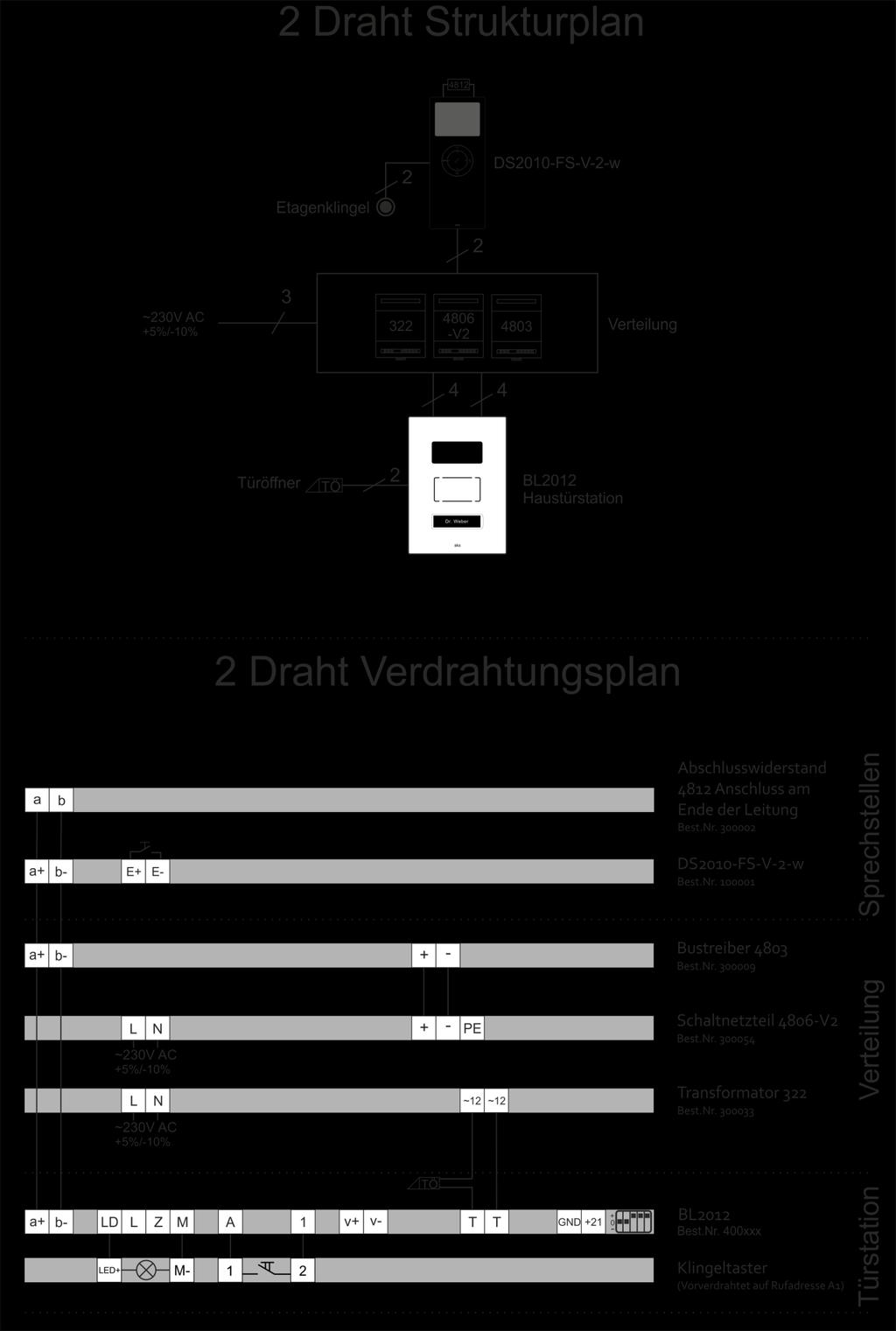
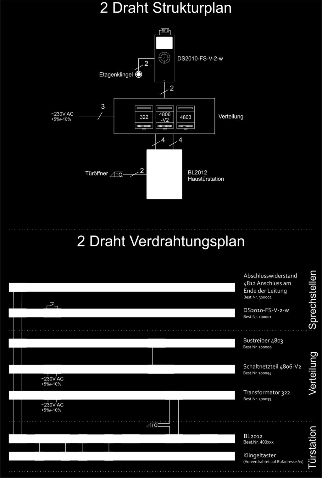
4 3. Klemmenbezeichnungen kombiniertes Kamera-/Sprachmodul Klemme Bezeichnung Bemerkung a+ BUS-Klemme (positiv) b- BUS-Klemme (negativ) T,T Türöffner (Relaiskontakt) Lastwiderstand >8Ohm M Gemeinsamer Anschluss der Steuersignale LD Anschluss der LED Namensschildbeleuchtung Für max. 2 Namensschilder Z Steuersignal für Türumschalter Nur bei 6-Draht Version L Steuersignal für Video-Kamera Nur bei 2-Draht Version Bei mehr als 2 LED Namensschildbeleuchtungen erfolgt die Versorgung über den 322 Transformator mit 12VAC 4. Klemmenbezeichnungen Klingeltaster Klemme Bezeichnung M- Negativer Anschluss der LED-Namensschildbeleuchtung LED+ A bis D (je nach Ausführung) Positiver Anschluss der LED-Namensschildbeleuchtung Erster Anschluss Klingeltaste 1 bis 8 (je nach Ausführung) Zweiter Anschluss Klingeltaste ~ 4 ~
5 5. Montageanleitung Das Öffnen einer bereits montierten Türstation ist unter Punkt 6. Öffnen einer montierten Türstation beschrieben. Die Türstationen lassen sich nur mit dem speziellen Öffnungswerkzeug öffnen. Verwenden Sie keine Schraubenzieher oder dergleichen um, die Türstation zu öffnen. Öffnen Sie die Türstation niemals gewaltsam. Stecken Sie das Öffnungswerkzeug wie links im Bild 1 und 2 dargestellt in die am unteren Ende befindliche Öffnung der Frontplatte. Halten Sie den Unterputzkasten der Türstation wie im Bild 3. gezeigt mit der linken Hand fest. Ziehen Sie mit der rechten Hand das Öffnungswerkzeug zu sich und anschließend nach oben bis Sie einen Klick hören. Entnehmen Sie die Frontplatte. Halten Sie den Unterputzkasten der Türstation wie gezeigt mit der linken Hand fest und entnehmen Sie mit der rechten Hand die Frontplatte. Für die Kabeldurchführung sind mehrere Sollbruchstellen an der Ober- und Unterseite vorgesehen. Die gewünschte Kabeldurchführung mit einem geeigneten Werkzeug z.b. Schraubenzieher durchstoßen. Die optimale Einbauhöhe ist 1,45 bis 1,60 m, Bezugspunkt Kamera Objektiv. ~ 5 ~
6 Montageanleitung (Fortsetzung) Der Unterputzkasten ist in einem passgenauen Mauerausschnitt zu montieren. In der unteren Tabelle sind die Abmessungen des Unterputzkastens nach Anzahl der Klingeltasten aufgelistet. Klingeltasten Abmessungen (BxHxT) x 177 x 46 mm x 202 x 46 mm x 227 x 46 mm x 252 x 46 mm x 277 x 46 mm x 302 x 46 mm x 327 x 46 mm x 352 x 46 mm Ziehen Sie das Kabel in die durchstoßene Öffnung ein. Achten Sie darauf, dass genügend Kabel zum Anschluss der Türstation vorhanden ist. Zum Einputzen wird der Kasten mit vier Schrauben im Mauerwerk verschraubt. Prüfen Sie vor dem Einputzen, dass der Unterputzkasten plan zur Wand verläuft. Putzen Sie den Unterputzkasten wie im linken Bild gezeigt vollständig ein. Ist der Unterputzkasten zu tief eingeputzt, können die Halteleisten mit Hilfe der zwei Schrauben parallel verschoben werden. Dadurch ist ein Tiefenausgleich von maximal 9mm möglich. Lösen Sie die Schrauben und ziehen Sie die Halteleiste soweit raus, bis diese plan zur Wand verlaufen. Andernfalls lässt sich die Frontplatte nicht einsetzen. ~ 6 ~
7 Montageanleitung (Fortsetzung) SKS 2-Draht-Video-Bus Die Türstation wird über die Klemmen a+/b- an den 2- Draht-Video-Bus angeschlossen. An die Klemmen T/T wird der Türöffner angeschlossen (potenzialfreier Schaltkontakt). Versorgt wird der Türöffner über einen separaten Wechselspannungstrafo. Mit den Klemmen M/LD wird die LED-Namensschildbeleuchtung für max. 2 Namensschilder versorgt. Die Klemme L ist nur bei Verwendung externer Kameras mit einem (825-M) 2-Draht Sender Art.Nr nötig. Stellen Sie am DIP-Schalter die gewünschte Türstationsadresse ein. Die Einstellungen sind unter Punkt 7. DIP-Schalter-Einstellungen beschrieben. Stecken Sie die Anschluss-Klemme auf. Setzen Sie die Oberkante der Frontplatte in den Unterputzkasten ein. Anschließend mit einem leichten Druck nach oben die Unterkante der Frontplatte bis zum Klick gegen den Unterputzkasten drücken. Lässt sich die Frontplatte nicht einsetzen, sind evtl. die Halteleiten nicht richtig eingestellt. Korrigieren Sie die Position der Halteleisten wie zuvor beschrieben. ~ 7 ~
8 6. Öffnen einer montierten Türstation Die Türstationen lassen sich nur mit dem speziellem Öffnungswerkzeug öffnen. Verwenden Sie keine Schraubenzieher oder der gleichen um die Türstation zu öffnen. Öffnen Sie die Türstation niemals gewaltsam. Das Öffnungswerkzeug kann auch separat bei SKS Kinkel Elektronik GmbH bestellt werden. Stecken Sie das Öffnungswerkzeug wie links im Bild 1 dargestellt mit dem schmalen Teil bis zum ersten Anschlag in die am unteren Ende befindliche Öffnung der Frontplatte. Drücken Sie wie im Bild 2 gezeigt, das Öffnungswerkzeug von sich weg. Die Frontplatte hebt sich ca. 5mm von der Wand ab. Halten Sie die Frontplatte mit den Fingern fest, damit sie nicht in die Verriegelung zurückspringt. Schieben Sie, wie im Bild 3 dargestellt, das Öffnungswerkzeug bis zum zweiten Anschlag von unten in die Türstation. Ziehen Sie erneut das Öffnungswerkzeug zu sich, bis Sie einen Klick hören. Entnehmen Sie die Frontplatte wie im Bild links dargestellt. Entnehmen Sie die Frontplatte wie im Bild links dargestellt. Der Zusammenbau ist auf den vorherigen Seiten beschrieben. ~ 8 ~
 3,5 Sekunden 5,0 Sekunden 7.")
9 7. DIP-Schalter-Einstellungen 7.1 Türöffnerzeit einstellen Mit dem DIP-Schalter Nr.2 lässt sich die Türöffnerzeit von 2 bis 5 Sekunden einstellen. Die Tabelle zeigt die Türöffnerzeiten und die dazugehörige DIP-Schaltereinstellung. DIP-Schalter Position Türöffnerzeit 2,0 Sekunden (Standard) 3,5 Sekunden 5,0 Sekunden 7.2 Türstationsadresse Das linke Bild zeigt die DIP-Schalter-Einstellungen für die Türstationsadresse. Wird nur eine Türstation verwendet, ist die Türstationsadresse 1 zu benutzen. Werden mehrere Türstationen verwendet, muss jede Türstation eine andere Türstationsadresse haben. Nur die DIP-Schalter 4 und 5 werden für die Türstationsadresse verwendet. 8. Rufadressen der Klingeltasten Es wird immer mit der Rufadresse A1 begonnen, wenn keine Sonderversion bestellt wurde. Die unten dargestellten Bilder zeigen die Rufadresse je nach Anzahl der Klingeltasten von der Türstation. Die Innensprechstellen haben ebenfalls alle einen DIP-Schalter, an dem die Rufadresse eingestellt wird. Ist die Rufadresse an der Türstationsklingeltaste gleich der Rufadresse, die am DIP-Schalter an der Innensprechstelle eingestellt ist, ist die Programmierung abgeschlossen. Durch Drücken des Klingeltasters klingelt dann die zugehörige Innensprechstelle. Im Anhang finden Sie die DIP-Schalter- Einstellung zu jeder Rufadresse. Weitere Information finden Sie auch in der Installationsanleitung der jeweiligen Sprechstelle. Rufadressen der Klingeltasten A8 A7 A6 A5 A4 A3 A2 A1 ~ 9 ~
10 9. Namensschilder einlegen oder wechseln Die Namensschilder lassen sich von der Vorderseite aus wechseln. Verwenden Sie nur das SKS- Entnahmewerkzeug Art.Nr , um die Namensschilder zu wechseln. Verwenden Sie keine Schraubenzieher oder dergleichen. Das Entnahmewerkzeug kann auch separat bei SKS Kinkel Elektronik GmbH bestellt werden. Stecken Sie das Entnahmewerkzeug in den rechts neben dem Namensschild befindlichen Schlitz. Ziehen Sie das Entnahmewerkzeug mit einem leichten Druck nach links an das Namensschild zu sich, bis das Namenschild um ca. 20 geöffnet ist. Um das Namenschild vollständig zu öffnen, ziehen Sie das Namensschild bis zum Anschlag nach rechts und anschließend zu sich. Das Namensschild lässt sich bis auf 90 öffnen. ~ 10 ~
11 Entnehmen Sie das alte Namensschild und legen Sie das neue Namensschild ein. Schließen Sie vorsichtig das Namensschild wieder bis auf ca. 20. Drücken Sie anschließend das Namensschild bis zum Anschlag nach links. Drücken Sie bis zum Klick gegen das Namenschild, um es vollständig zu schließen. ~ 11 ~
12 10. Teilnehmer rufen Berühren Sie den Klingelknopf/Namen des gewünschten Teilnehmers. Der Teilnehmer wird gerufen. Für den Besucher ertönt ein Bestätigungston an der Türstation, dass bei dem Teilnehmer geklingelt wird. ~ 12 ~
13 11. Pflegehinweise Reinigen Sie die Türstation nur mit einem weichen Tuch, welches mit einer milden Seifenlösung angefeuchtet ist. Trockene Reinigung, aggressive Reiniger und Scheuermittel können die Oberfläche beschädigen. 12. Technische Daten Elektrische Daten Eingangsspannung a+ / b- Ausgangsspannung L / M Ausgangsstrom L / M VDC 3 4 VDC Maximal 15 ma Namensschild Beleuchtungen an LD / M Maximal 2 Allgemeines Einbauhöhe der Türstation Lichtempfindlichkeit Auflösung 1,45 bis 1,60 m (Bezug Kamera Objektiv) 0,2 Lux (Farbe) und 0,05 Lux (schwarz/weiß) PAL, 795H x 596V Pixel, 650 TV-Linien Blickwinkel Horizontal 100 und Vertikal 80 Temperatur -10 C bis +50 C Feuchtigkeit Gehäuse Abmessungen Front (Breite x Höhe x Tiefe) Schutzklasse 20 % bis 90 % nicht kondensierend Kunststoffgehäuse 135 x 190 bis 365 x 4 mm (50 mm mit UP-Kasten) IP Service Für die Gewährleistung gelten die gesetzlichen Bestimmungen. Der Austausch des Gerätes im Servicefall erfolgt durch Ihren Elektroinstallateur. CE Hinweise Dies ist eine Einrichtung der Klasse A. Haftungsausschluss Wir haben den Inhalt der Druckschrift auf Übereinstimmung mit der beschriebenen Hard-und Software geprüft. Es können dennoch Abweichungen nicht ausgeschlossen werden, so dass wir für die vollständige Übereinstimmung keine Gewähr übernehmen. Die Angaben dieser Druckschrift werden regelmäßig überprüft und notwendige Korrekturen sind in den nachfolgenden Auflagen enthalten. ~ 13 ~
14 ~ 14 ~
15 Door Station Basic Line 2012 (2-Wire Video SKS-Bus) Version 1.2 ~ 15 ~
16 Table of Contents 1. General Information on Video-Bus Installation Terminals for the combined camera-/ voice module Terminals for bell buttons Mounting instructions Opening a mounted door station DIP switch settings Setting the door opening interval Door station address Addresses of the bell buttons Inserting or changing nameplates Calling instructions Care instructions Technical data Service Sample of a wiring scheme und structural plan 28 ~ 16 ~
17 1. General Information on 2-Wire Video-Bus Loop resistance from distributor to telephone inside station may only be a maximum of 8Ω. From distribution to door station loop resistance may not exceed 6Ω. The maximum distance between door station and last indoor station may not exceed 200 m. BUS Voltage has to be between V. Twisted pair wire is to be used for Bus lines and also for all other shown functions. The recommended wire is: JY (St) Y in 0.8 mm. If required the shield is to be statically grounded. Up to three stations may be configured using one identical address (parallel operation). In case of radial layout of wiring or if long distances have to be covered hubs are required. Using additional switch modules it is, for example, possible to actuate light sensors, automatic door openers or other functions. For the installation it is mandatory to adhere to the VDE 0100 und VDE 0800 guidelines. (Germany) 2. Installation Hazard of electrical strike and burns to persons, as well as damage of equipment and malfunctions. Observe VDE 0100 and VDE 0800 guidelines during installation. (Germany) Countermeasures: Before beginning any work, deactivate and disconnect all energized electrical wires. Secure the switched off/ disconnected lines against erreneous reconnection. Use a measuring device to make sure that the wires are deenergized. Cover up any adjacent, energized or conducting components. All work and all electrical connections must comply with the national provisions for the country in question and must be performed by appropriately trained personnel. DIN VDE 0100 must be observed and complied with in devices with a 230V connection ~ 17 ~
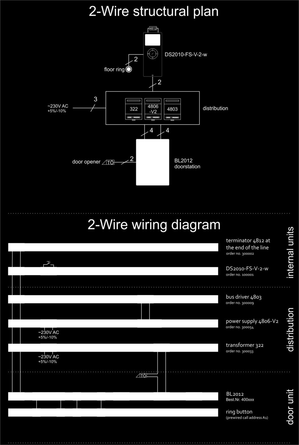
18 3. Terminals for combined camera / voice module Terminal Description Notes a+ Bus-terminal (positive) b- Bus-terminal (negative) T,T Door opener (relay contact) Load resistance > 8 Ohm M Combined connection for control signals LD Connection of LED name plate illumination Max. 2 name plates Z Control signal for door changer For 6-wire version only L Control signal for video camera For 2-wire version only If there are more than 2 LED name plate illuminations, the power supply is accomplished via the 322 transformer with 12VAC. 4. Terminals for bell buttons Terminal Description M- Negative connection of LED name plate illumination LED+ A to D (depending on model) Positive connection of LED name plate illumination First connection bell button 1 to 8 (depending on model) Second connection bell button ~ 18 ~

19 5. Mounting instructions Opening an already mounted door station is explained in section 6 (Opening a mounted door station). Door stations may only be opened with a special tool. Do not use regular screw drivers or similar tools to open it and never apply force. As shown in figures 1 and 2 on the left, use one hand to insert the opening tool into the opening on the bottom of the front panel. With the other hand hold on to the housing of the door station as demonstrated in figure 3. Then pull the opening tool towards you and then upwards until you hear a click sound. Remove the front panel. As shown in the figure on the left, hold on to the housing of the door station with one hand and lift the front panel with the other hand. Several predetermined breaking points on the top and the bottom are provided for the cable feed through. The selected entry point may be pushed open with an appropriate tool, e.g. a screwdriver. The optimum installation height is 1.45 to 1.60 m, with the reference point being the camera lens. ~ 19 ~
20 Mounting instructions (continued) The in-wall box is to be flush-mounted into a cutout / notch in the wall. The table below provides a list of the dimensions of the in-wall boxes according to their number of bell buttons. Bell buttons Dimensions (WxHxD) x 177 x 46 mm x 202 x 46 mm x 227 x 46 mm x 252 x 46 mm x 277 x 46 mm x 302 x 46 mm x 327 x 46 mm x 352 x 46 mm Feed the cable through the selected openings into the box. Make sure there is enough cable to connect the door station. The housing is mounted to the wall using 4 screws. Before mounting and completing the plastering work (as shown on the left) it is inevitable to check whether the housing is flush with the wall. Then complete the mounting by covering the box with plaster. If the in-wall box ends up too deep in the wall, the retaining ledges may be moved parallel using the two screws. This allows for an adjustment in depth of up to a maximum of 9mm. Once the screws are loosened the retaining ledge may be pulled out until it is flush with the wall. If this is not the case, the front panel may not be mounted. ~ 20 ~
. Power for the door opener is supplied by a separate AC voltage transformer.")
21 Mounting instructions (continued) SKS 2-Wire Video Bus Using the a+/b- terminals the door station is connected to the 2-wire video bus. The door opener is connected at the T/T terminals (potential-free switch contact). Power for the door opener is supplied by a separate AC voltage transformer. The M/LD terminal is used for the LED name plate illumination of maximally 2 name plates. Terminal L is only required for the installation of external cameras which use a (825-M) 2-wire transmitter Part.No Set the selected door station address at the DIP switch. The settings are described in section 7 at DIPswitch settings. Clip on the terminal. Fit the top part of the front panel into the in-wall housing. Then slightly press (apply only light pressure) the bottom part of the front panel in an upward direction against the housing until there is a click sound. If the front plate may not be put into place the retaining ledges may not be adjusted correctly. In this case correct their position as described above. ~ 21 ~
22 6. Opening a mounted door station Door stations may only be opened using a special opening tool. Do not use screw drivers or any other similar tools to open a door station. Never apply force when opening it. The opening kit may be ordered separately from SKS Kinkel Elektronik GmbH. Insert the narrow part of the opening tool all the way (until the first stop) into the opening located at the bottom of the front plate as shown in figure 1 on the left. As shown in figure 2 push the opening device away from you. The front plate may be lifted about 5mm away from the wall. With your fingers hold on to the front plate to keep it from sliding back. Then continue pushing the opening tool all the way in until the second stop is reached (see picture 3). Again pull the opening device toward you until you hear a click sound. Remove the front plate as shown in the picture on the left. Remove the front plate as shown in the picture on the left. How to put it back in is described on the previous pages. ~ 22 ~
23 7. DIP switch settings 7.1 Setting the door opening interval DIP switch No. 2 may be used to set the delay in the opening time of the door to 2 to 5 seconds. The table shows the interval the door will stay open and the corresponding DIP switch settings DIP switch position dooropening time 2.0 seconds (standard) 3.5 seconds 5.0 seconds 7.2 Door station address The picture on the left shows the DIP switch setting for the door station address. If only one door station is used, address 1 is required. If several door stations are used, every door station must have a different door station address. Only the DIP switches 4 and 5 are used for the door station address. 8. Addresses of the bell buttons If there was no special order, the addresses always begin with A1. The pictures below show the addresses in accordance with the number of bell buttons at the door station. The indoor stations also have a DIP switch at which the call address is set. Once the call address at the door station bell button is the same as the call address set at the DIP switch at the indoor station, programming has been completed. When the bell button is pushed, the respective indoor station will ring. The DIP switch settings for each call address are listed in the Appendix. Additional information can also be found in the instructions for mounting the individual stations. Call address of bell buttons A8 A7 A6 A5 A4 A3 A2 A1 ~ 23 ~
24 9. Inserting or changing name plates Name plates may be changed from the front. Only the SKS removal tool (article number ) may be used to change name plates. Do not use any screw drivers or any similar tools. The removal tool may be ordered individually from SKS Kinkel Elektronik GmbH. Stick the removal tool into the slot located on the right next to the name plate. Exerting light pressure towards the name plate on the left, pull the removal tool towards you until the removed side of the name plate reaches a 20 angle. To completely open the name name plate pull it all the way to the right until the stop and then forward towards yourself. The name plate may be opened up to an angle of 90. ~ 24 ~
25 Remove the old name tag and replace it with the new one. Carefully close the name plate until it reaches the 20 angle. Then press the name plate to the left until it reaches the stop. Press until you hear a click to make sure it is completely back in place. ~ 25 ~

26 10. Calling instructions Touch the bell button / name of the party called. The party is being called. To let the visitor know that the called party is actually receiving a ring tone there will be a confirmation tone at the door station as well. ~ 26 ~
27 11. Care instructions Only clean the door station with a soft cloth which has been dampened with mild soap. Dry cloth, aggressive cleaning agents and scrub cleansers may damage the surface. 12. Technical data Electrical data Input voltage a+ / b- Output voltage L / M Output current L / M VDC 3 4 VDC Maximum 15 ma Name plate illumination at LD / M Maximum 2 General data Installation height of door station Light sensitivity Resolution 1.45 to 1.60 m (reference is the camera lens) 0.2 lux (color) and 0.05 lux (black/white) PAL, 795H x 596V Pixel, 650 TV-Lines View angle Horizontal 100 und Vertical 80 Temperature -10 C to +50 C Humidity Housing Dimensions of front (width x height x depth) IP Code 20 % to 90 % non-condensing Plastic housing 135 x 190 to 365 x 4 mm (50 mm with in-wall box) IP Service For the warranty applies the legal requirements. The exchange of the device in a service issue shall be made by an electrician. CE Notes This is a Class A device. Disclaimer of liability We have checked the conted of the printed material to compliance with the described hardware and software. However deviations may occur, therefore no liability is assumed regarding complete compliance. The information in this publication is reviewed regularly and necessary corrections are uncluded in the following editions. ~ 27 ~
28 ~ 28 ~

29 DIP-Schaltereinstellungen für Innensprechstellen, Schaltaktor und TK-Adapter DIP-Switch settings for intercoms, switch actuator and TK-Adapter Standard Rufasdressenbereich Erweiterter Rufadressenbereich Standard call address range Extended call address range Anhang, Appendix ~ 29 ~
RS232-Verbindung, RXU10 Herstellen einer RS232-Verbindung zwischen PC und Messgerät oder Modem und Messgerät
 Betriebsanleitung RS232-Verbindung, RXU10 Herstellen einer RS232-Verbindung zwischen PC und Messgerät oder Modem und Messgerät ä 2 Operating Instructions RS232 Connection, RXU10 Setting up an RS232 connection
Installation Instructions
 EN DE Installation Instructions WLAN Installation Kit, 300 Mbps, 5 GHz, 16 dbi AK-4 Wireless Kit Scope of delivery Junction box AK-4 (1x) 1 Connection board AK-4 CB with 12VDC power supply unit (1x) 2
UWC 8801 / 8802 / 8803
 Wandbedieneinheit Wall Panel UWC 8801 / 8802 / 8803 Bedienungsanleitung User Manual BDA V130601DE UWC 8801 Wandbedieneinheit Anschluss Vor dem Anschluss ist der UMM 8800 unbedingt auszuschalten. Die Übertragung
300Mbps Wireless Outdoor PoE Access Point/Bridge Quick Installation Guide
 LevelOne WAB-5120 300Mbps Wireless Outdoor PoE Access Point/Bridge Quick Installation Guide English Deutsch - 1 - Table of Content English... - 3 - Deutsch... - 9 - This guide covers only the most common
How-To-Do. Hardware Configuration of the CC03 via SIMATIC Manager from Siemens
 How-To-Do Hardware Configuration of the CC03 via SIMATIC Manager from Siemens Content Hardware Configuration of the CC03 via SIMATIC Manager from Siemens... 1 1 General... 2 1.1 Information... 2 1.2 Reference...
CABLE TESTER. Manual DN-14003
 CABLE TESTER Manual DN-14003 Note: Please read and learn safety instructions before use or maintain the equipment This cable tester can t test any electrified product. 9V reduplicated battery is used in
NEWSLETTER. FileDirector Version 2.5 Novelties. Filing system designer. Filing system in WinClient
 Filing system designer FileDirector Version 2.5 Novelties FileDirector offers an easy way to design the filing system in WinClient. The filing system provides an Explorer-like structure in WinClient. The
Parameter-Updatesoftware PF-12 Plus
 Parameter-Updatesoftware PF-12 Plus Mai / May 2015 Inhalt 1. Durchführung des Parameter-Updates... 2 2. Kontakt... 6 Content 1. Performance of the parameter-update... 4 2. Contact... 6 1. Durchführung
Softwareupdate-Anleitung // AC Porty L Netzteileinschub
 1 Softwareupdate-Anleitung // AC Porty L Netzteileinschub Softwareupdate-Anleitung // AC Porty L Netzteileinschub HENSEL-VISIT GmbH & Co. KG Robert-Bunsen-Str. 3 D-97076 Würzburg-Lengfeld GERMANY Tel./Phone:
Release Notes BRICKware 7.5.4. Copyright 23. March 2010 Funkwerk Enterprise Communications GmbH Version 1.0
 Release Notes BRICKware 7.5.4 Copyright 23. March 2010 Funkwerk Enterprise Communications GmbH Version 1.0 Purpose This document describes new features, changes, and solved problems of BRICKware 7.5.4.
p^db=`oj===pìééçêíáåñçêã~íáçå=
 p^db=`oj===pìééçêíáåñçêã~íáçå= Error: "Could not connect to the SQL Server Instance" or "Failed to open a connection to the database." When you attempt to launch ACT! by Sage or ACT by Sage Premium for
KURZANLEITUNG. Firmware-Upgrade: Wie geht das eigentlich?
 KURZANLEITUNG Firmware-Upgrade: Wie geht das eigentlich? Die Firmware ist eine Software, die auf der IP-Kamera installiert ist und alle Funktionen des Gerätes steuert. Nach dem Firmware-Update stehen Ihnen
Schnell-Start-Anleitung Quick Start Guide
 Schnell-Start-Anleitung Quick Start Guide 3 1. Cube anschließen Schließen Sie den Cube an die Stromversorgung an. Verbinden Sie den Cube mit dem Router. Die Power- und die Internet-LED beginnen zu blinken,
Cisco SSPA122. Installation und manuelle Rekonfiguration. Dokumentenversion 1
 Cisco SSPA122 Installation und manuelle Rekonfiguration Dokumentenversion 1 Placetel UC-One Cisco SPA122 Installation und manuelle Rekonfiguration Copyright Hinweis Copyright 2015 finocom AG Alle Rechte
Load balancing Router with / mit DMZ
 ALL7000 Load balancing Router with / mit DMZ Deutsch Seite 3 English Page 10 ALL7000 Quick Installation Guide / Express Setup ALL7000 Quick Installation Guide / Express Setup - 2 - Hardware Beschreibung
Frequently asked Questions for Kaercher Citrix (apps.kaercher.com)
") Frequently asked Questions for Kaercher Citrix (apps.kaercher.com) Inhalt Content Citrix-Anmeldung Login to Citrix Was bedeutet PIN und Token (bei Anmeldungen aus dem Internet)? What does PIN and Token
Frequently asked Questions for Kaercher Citrix (apps.kaercher.com) Inhalt Content Citrix-Anmeldung Login to Citrix Was bedeutet PIN und Token (bei Anmeldungen aus dem Internet)? What does PIN and Token
1. General information... 2 2. Login... 2 3. Home... 3 4. Current applications... 3
 User Manual for Marketing Authorisation and Lifecycle Management of Medicines Inhalt: User Manual for Marketing Authorisation and Lifecycle Management of Medicines... 1 1. General information... 2 2. Login...
Worx Landroid - Software Update
 Worx Landroid - Software Update WORX Landroid Software Update für Anwender 30.04.2015 Website: www.worxlandroid.com Direct Direkter Link Link for auf the Update: Update: https://www.worxlandroid.com/en/software-update
Anleitung zur Schnellinstallation TFM-560X YO.13
 Anleitung zur Schnellinstallation TFM-560X YO.13 Table of Contents Deutsch 1 1. Bevor Sie anfangen 1 2. Installation 2 Troubleshooting 6 Version 06.08.2011 1. Bevor Sie anfangen Packungsinhalt ŸTFM-560X
Service Manual Kugelgelenke an DT Swiss Dämpfer ersetzen Replace spherical bearings on DT Swiss shocks
 Service Manual Kugelgelenke an DT Swiss Dämpfer ersetzen Replace spherical bearings on DT Swiss shocks www.dtswiss.com - Inhaltsverzeichnis / Table of contents Einleitung... 2 Instructions... 2 Montage
Beipackzettel Instruction leaflet
 Beipackzettel Instruction leaflet Montage an einen Wandarm Mounting to wall arm Pepperl+Fuchs GmbH Antoniusstr. 21 D-73249 Wernau Germany Tel.: +49(0) 621 776-3712 Fax: +49(0) 621 776-3729 www.pepperl-fuchs.com
v i r t u A L C O M P o r t s
 v i r t u A L C O M P o r t s (HO720 / HO730) Installieren und Einstellen Installation and Settings Deutsch / English Installieren und Einstellen des virtuellen COM Ports (HO720 / HO730) Einleitung Laden
ALL1681 Wireless 802.11g Powerline Router Quick Installation Guide
 ALL1681 Wireless 802.11g Powerline Router Quick Installation Guide 1 SET ALL1681 Upon you receive your wireless Router, please check that the following contents are packaged: - Powerline Wireless Router
miditech 4merge 4-fach MIDI Merger mit :
 miditech 4merge 4-fach MIDI Merger mit : 4 x MIDI Input Port, 4 LEDs für MIDI In Signale 1 x MIDI Output Port MIDI USB Port, auch für USB Power Adapter Power LED und LOGO LEDs Hochwertiges Aluminium Gehäuse
Software-Update Version 1.0.10 manual. In order to keep your door systems updated, please proceed with the following changes.
 Software-Update Version 1.0.10 manual In order to keep your door systems updated, please proceed with the following changes. 1. Exchange CPU -Z1 (E60-0228-10) by the new one you already received. Front
Directions. Trouble shooting
 Betriebsanleitung 1. Legen Sie die Uhr mit der Vorderwand auf den Tisch und öffnen Sie die Rückwand des Uhrengehäuses (A). 2. Entfernen Sie das Papier welches zwischen die Rückwand und Tonfeder geklemmt
SmartClass Firmware-Update Vorgehensweise
 Benutzeranweisungen SmartClass Firmware-Update Vorgehensweise 2008.01 (V 1.x.x) Deutsch Please direct all enquiries to your local JDSU sales company. The addresses can be found at: www.jdsu.com/tm-contacts
User Manual Bedienungsanleitung. www.snom.com. snom Wireless Headset Adapter snom Schnurlos-Headset-Adapter. English. Deutsch
 English snom Wireless Headset Adapter snom Schnurlos-Headset-Adapter Deutsch User Manual Bedienungsanleitung 2007 snom technology AG All rights reserved. Version 1.00 www.snom.com English snom Wireless
INSTALLATION AND OPERATING INSTRUCTIONS FOR LPS203-M LPS203-M 操 作 指 示
 BEDIENUNGSANLEITUNG To comply with the published safety standards, the following must be observed when using this power supply. Um den zur Zeit gültigen Sicherheitsbestimmungen zu genügen, müssen die nachstehenden
MATLAB driver for Spectrum boards
 MATLAB driver for Spectrum boards User Manual deutsch/english SPECTRUM SYSTEMENTWICKLUNG MICROELECTRONIC GMBH AHRENSFELDER WEG 13-17 22927 GROSSHANSDORF GERMANY TEL.: +49 (0)4102-6956-0 FAX: +49 (0)4102-6956-66
Montageanleitung / Mounting Instructions. CELSIUS M / R / V / W Rack Kit
 Montageanleitung / Mounting Instructions System CELSIUS M / R / V / W Rack Kit Congratulations on your purchase of an innovative product from Fujitsu. The latest information about our products, tips, updates
Notice: All mentioned inventors have to sign the Report of Invention (see page 3)!!!
!!!") REPORT OF INVENTION Please send a copy to An die Abteilung Technologietransfer der Universität/Hochschule An die Technologie-Lizenz-Büro (TLB) der Baden-Württembergischen Hochschulen GmbH Ettlinger Straße
REPORT OF INVENTION Please send a copy to An die Abteilung Technologietransfer der Universität/Hochschule An die Technologie-Lizenz-Büro (TLB) der Baden-Württembergischen Hochschulen GmbH Ettlinger Straße
Cable Tester NS-468. Safety instructions
 Cable Tester NS-468 Safety instructions Do not use the cable tester NS-468 if it is damaged. This device is only for use inside dry and clean rooms. This device must be protected from moisture, splash
Der Adapter Z250I / Z270I lässt sich auf folgenden Betriebssystemen installieren:
 Installationshinweise Z250I / Z270I Adapter IR USB Installation hints Z250I / Z270I Adapter IR USB 06/07 (Laden Sie den Treiber vom WEB, entpacken Sie ihn in ein leeres Verzeichnis und geben Sie dieses
ONLINE LICENCE GENERATOR
 Index Introduction... 2 Change language of the User Interface... 3 Menubar... 4 Sold Software... 5 Explanations of the choices:... 5 Call of a licence:... 7 Last query step... 9 Call multiple licenses:...
PCTV DVB-S2 Stick (461e) Quick Start Guide Kurzanleitung
 Quick Start Guide Kurzanleitung") PCTV DVB-S2 Stick (461e) Quick Start Guide Kurzanleitung 2013 PCTV Systems S.à r.l. QI-461E-V1-4LANG Lieferumfang 1 2 3 4 5 6 Installation I. II. III. IV. V. VI. Lieferumfang* Beispielhafte Abbildungen
PCTV DVB-S2 Stick (461e) Quick Start Guide Kurzanleitung 2013 PCTV Systems S.à r.l. QI-461E-V1-4LANG Lieferumfang 1 2 3 4 5 6 Installation I. II. III. IV. V. VI. Lieferumfang* Beispielhafte Abbildungen
www.infoplc.net AC500 Application Example Scalable PLC for Individual Automation AC500-eCo Modbus TCP/IP Data Exchange between two AC500-eCo CPUs
 Application Example AC500 Scalable PLC for Individual Automation AC500-eCo Modbus TCP/IP Data Exchange between two AC500-eCo CPUs Content 1 Disclaimer...2 1.1 For customers domiciled outside Germany /
Instruktionen Mozilla Thunderbird Seite 1
 Instruktionen Mozilla Thunderbird Seite 1 Instruktionen Mozilla Thunderbird Dieses Handbuch wird für Benutzer geschrieben, die bereits ein E-Mail-Konto zusammenbauen lassen im Mozilla Thunderbird und wird
ReadMe zur Installation der BRICKware for Windows, Version 6.1.2. ReadMe on Installing BRICKware for Windows, Version 6.1.2
 ReadMe zur Installation der BRICKware for Windows, Version 6.1.2 Seiten 2-4 ReadMe on Installing BRICKware for Windows, Version 6.1.2 Pages 5/6 BRICKware for Windows ReadMe 1 1 BRICKware for Windows, Version
SanStore: Kurzanleitung / SanStore: Quick reference guide
 SanStore Rekorder der Serie MM, MMX, HM und HMX Datenwiedergabe und Backup Datenwiedergabe 1. Drücken Sie die Time Search-Taste auf der Fernbedienung. Hinweis: Falls Sie nach einem Administrator-Passwort
Honeywell AG Hardhofweg. D-74821 Mosbach MU1H-1220GE23 R1001
 BA 95 Einbau-Anleitung Installation Instructions Einbau Installation Einbaubeispiel Installation example Ablaufleitung vorsehen Install discharge pipework Durchflussrichtung beachten! Consider direction
fastpim 1 H fast switching H bridge module Features: - 1 Phase Input Rectifier Bridge - 1 Phase fast switching IGBT + FRED full H bridge - NTC
 fast switching H bridge module Features: - 1 Phase Input Rectifier Bridge - 1 Phase fast switching IGBT + FRED full H bridge - NTC Copyright by Vincotech 1 Revision: 1 module types / Produkttypen Part-Number
Installation guide for Cloud and Square
 Installation guide for Cloud and Square 1. Scope of delivery 1.1 Baffle tile package and ceiling construction - 13 pcs. of baffles - Sub construction - 4 pcs. of distance tubes white (for direct mounting)
BECOscreen BERHALTER continously and efficiently screen changer
 T E C - S P I R A T I O N technology meets inspiration swiss made BECOscreen BERHALTER continously and efficiently screen changer your partner for melt filtration system screenchanger BERHALTER BECOscreen
E/A-Bedieneinheit. I/O Control unit 658552 DE/GB 08/02
 E/A-Bedieneinheit I/O Control unit 527429 658552 DE/GB 08/02 Best.-Nr.: 658552 Benennung: DATENBLATT Bezeichnung: D:LP-BED.EINH.-E/A-DE/GB Stand: 08/2002 Autoren: Christine Löffler Grafik: Doris Schwarzenberger
C R 2025 C LOSE PUSH OPEN
 3V C R 2025 C LOSE PUSH OPEN ) ) ) 25 222 3V C R 2025 C LOSE PUSH OPEN 25 222 3V C R 2025 C LOSE PUSH OPEN 25 222 Den här symbolen på produkten eller i instruktionerna betyder att den elektriska
NVR Mobile Viewer for iphone/ipad/ipod Touch
 NVR Mobile Viewer for iphone/ipad/ipod Touch Quick Installation Guide DN-16111 DN-16112 DN16113 2 DN-16111, DN-16112, DN-16113 for Mobile ios Quick Guide Table of Contents Download and Install the App...
EMCO Installationsanleitung Installation instructions
 EMCO Installationsanleitung Installation instructions Installationsanleitung Installation instructions Digitalanzeige digital display C40, FB450 L, FB600 L, EM 14D/17D/20D Ausgabe Edition A 2009-12 Deutsch...2
roll-up SONJA powerdisplays Aufbauanleitung Assemble instructions
 powerdisplay SONJA Mit Rollfunktion! Die Werbefläche rollt sich vollständig in das Display. So ist Ihre Werbung geschützt und in Sekunden wieder aufgebaut. Farbe: chrom/silber inkl. Tasche With rolling
Technical Information
 Firmware-Installation nach Einbau des DP3000-OEM-Kits Dieses Dokument beschreibt die Schritte die nach dem mechanischen Einbau des DP3000- OEM-Satzes nötig sind, um die Projektoren mit der aktuellen Firmware
Contact 1600 QUICK REFERENCE GUIDE GUIDE D UTILISATION BEDIENUNGSANLEITUNG GUÍA DE REFERENCIA RÁPIDA GUIDA RAPIDA. www.sonybiz.net CHANGING THE WAY
 Contact 1600 CHANGING THE WAY QUICK REFERENCE GUIDE GUIDE D UTILISATION BEDIENUNGSANLEITUNG BUSINESS GUÍA DE REFERENCIA RÁPIDA GUIDA RAPIDA COMMUNICATES www.sonybiz.net GB Getting started STEP 1 Turning
Ingenics Project Portal
 Version: 00; Status: E Seite: 1/6 This document is drawn to show the functions of the project portal developed by Ingenics AG. To use the portal enter the following URL in your Browser: https://projectportal.ingenics.de
Wählen Sie das MySQL Symbol und erstellen Sie eine Datenbank und einen dazugehörigen User.
 1 English Description on Page 5! German: Viele Dank für den Kauf dieses Produktes. Im nachfolgenden wird ausführlich die Einrichtung des Produktes beschrieben. Für weitere Fragen bitte IM an Hotmausi Congrejo.
Batterie-Identifikations-Modul EL-BIM
 Bedienungs- und Montageanleitung Batterie-Identifikations-Modul EL-BIM 1.0 Allgemeines Das Batterie-Identifikations-Modul EL-BIM ermöglicht eine eindeutige Zuordnung von Ladevorgang und Batterie in den
GmbH, Stettiner Str. 38, D-33106 Paderborn
 Serial Device Server Der Serial Device Server konvertiert die physikalische Schnittstelle Ethernet 10BaseT zu RS232C und das Protokoll TCP/IP zu dem seriellen V24-Protokoll. Damit können auf einfachste
USB Treiber updaten unter Windows 7/Vista
 USB Treiber updaten unter Windows 7/Vista Hinweis: Für den Downloader ist momentan keine 64 Bit Version erhältlich. Der Downloader ist nur kompatibel mit 32 Bit Versionen von Windows 7/Vista. Für den Einsatz
Montageanweisung Mounting Instructions. ADSL/VDSL2 Splitter ADSL/VDSL2 Splitter
 Montageanweisung Mounting Instructions ADSL/VDSL2 Splitter ADSL/VDSL2 Splitter für 12 Teilnehmer for 12 subscribers Inhaltsverzeichnis Contents Seite / page 1 Anwendungsbereich Application area 3 2 Notwendige
Aufgabenstellung Mit welchen SICLOCK Produkten kann ich einen PC Zeitsynchronisieren?
 SICLOCK Application Note AN-0005 Titel Synchronisation von PCs mit SICLOCK Aufgabenstellung Mit welchen SICLOCK Produkten kann ich einen PC Zeitsynchronisieren? Schlüsselwörter SICLOCK DCFRS, WinGPS, GPS1000,
DE EN. Quick Start Guide. eneo Scan Device Tool
 DE EN Quick Start Guide eneo Scan Device Tool Inhalt Inhalt...2 Allgemeines...3 Beschreibung der einzelnen Funktionen...3 Umstellen der eigenen im PC zu verwendenden IP-Adresse...6 2 Allgemeines Das eneo
FLEX LIGHT. D Bedienungsanleitung
 FLEX LIGHT D Bedienungsanleitung GB INSTRUCTION Manual 3x Micro AAA 9 7 8 2 3 4 1 5 2 6 D Bedienungsanleitung FlexLight Beschreibung Multifunktionale Buch-/Laptop-Leuchte mit LED-Technologie (4). Das
E asyline by Hama GmbH & Co KG Postfach 80 86651 Monheim/Germany Tel. +49 (0)9091/502-0 Fax +49 (0)9091/502-274 hama@hama.de www.hama.
9091/502-0 Fax +49 (0)9091/502-274 hama@hama.de www.hama.") 00021024-10.06 E asyline by Hama GmbH & Co KG Postfach 80 86651 Monheim/Germany Tel. +49 (0)9091/502-0 Fax +49 (0)9091/502-274 hama@hama.de www.hama.com Gamepad Thunderstorm II 0021024 l Bedienungsanleitung
00021024-10.06 E asyline by Hama GmbH & Co KG Postfach 80 86651 Monheim/Germany Tel. +49 (0)9091/502-0 Fax +49 (0)9091/502-274 hama@hama.de www.hama.com Gamepad Thunderstorm II 0021024 l Bedienungsanleitung
iid software tools QuickStartGuide iid USB base RFID driver read installation 13.56 MHz closed coupling RFID
 iid software tools QuickStartGuide iid software tools USB base RFID driver read installation write unit 13.56 MHz closed coupling RFID microsensys Jun 2013 Introduction / Einleitung This document describes
Installationshinweise Z501J / Z501K Adapter IrDa USB Installation hints Z501J / Z501K Adapter IrDa USB
 Installationshinweise Z501J / Z501K Adapter IrDa USB Installation hints Z501J / Z501K Adapter IrDa USB 1/3.04 (Diese Anleitung ist für die CD geschrieben. Wenn Sie den Treiber vom WEB laden, entpacken
Nachdem Sie die Datei (z.b. t330usbflashupdate.exe) heruntergeladen haben, führen Sie bitte einen Doppelklick mit der linken Maustaste darauf aus:
 heruntergeladen haben, führen Sie bitte einen Doppelklick mit der linken Maustaste darauf aus:") Deutsch 1.0 Vorbereitung für das Firmwareupdate Vergewissern Sie sich, dass Sie den USB-Treiber für Ihr Gerät installiert haben. Diesen können Sie auf unserer Internetseite unter www.testo.de downloaden.
Deutsch 1.0 Vorbereitung für das Firmwareupdate Vergewissern Sie sich, dass Sie den USB-Treiber für Ihr Gerät installiert haben. Diesen können Sie auf unserer Internetseite unter www.testo.de downloaden.
p^db=`oj===pìééçêíáåñçêã~íáçå=
 p^db=`oj===pìééçêíáåñçêã~íáçå= How to Disable User Account Control (UAC) in Windows Vista You are attempting to install or uninstall ACT! when Windows does not allow you access to needed files or folders.
Invitation - Benutzerhandbuch. User Manual. User Manual. I. Deutsch 2. 1. Produktübersicht 2. 1.1. Beschreibung... 2
 Invitation - Inhaltsverzeichnis I. Deutsch 2 1. Produktübersicht 2 1.1. Beschreibung......................................... 2 2. Installation und Konfiguration 2 2.1. Installation...........................................
XAIR-Bridge: Installationshinweise XAIR-Bridge: Short Installation Guide (English Version on Page 10)
") XAIR-Bridge: Installationshinweise XAIR-Bridge: Short Installation Guide (English Version on Page 10) Bridge Ergänzung zu XAIR LOS GEHT S/GETTING STARTED Ziel und Zweck Diese Installationshinweise beschreiben
XAIR-Bridge: Installationshinweise XAIR-Bridge: Short Installation Guide (English Version on Page 10) Bridge Ergänzung zu XAIR LOS GEHT S/GETTING STARTED Ziel und Zweck Diese Installationshinweise beschreiben
Getting started with MillPlus IT V530 Winshape
 Getting started with MillPlus IT V530 Winshape Table of contents: Deutsche Bedienungshinweise zur MillPlus IT V530 Programmierplatz... 3 English user directions to the MillPlus IT V530 Programming Station...
eurex rundschreiben 094/10
 eurex rundschreiben 094/10 Datum: Frankfurt, 21. Mai 2010 Empfänger: Alle Handelsteilnehmer der Eurex Deutschland und Eurex Zürich sowie Vendoren Autorisiert von: Jürg Spillmann Weitere Informationen zur
!!! UNBEDINGT BEACHTEN!!!
 Produktinformation 201501_197PAdeen Deutsch Seite 1 5 English page 6 10 Solldaten-Update Achsvermessung 2015 WA 900 / 920 / 020 / 950 / 970 CURA S 800 / 860 / 060 / 900 / 960 WAB01 / WAB 02 CCT / RoboLigner
Kurzanleitung um Transponder mit einem scemtec TT Reader und der Software UniDemo zu lesen
 Kurzanleitung um Transponder mit einem scemtec TT Reader und der Software UniDemo zu lesen QuickStart Guide to read a transponder with a scemtec TT reader and software UniDemo Voraussetzung: - PC mit der
Abteilung Internationales CampusCenter
 Abteilung Internationales CampusCenter Instructions for the STiNE Online Enrollment Application for Exchange Students 1. Please go to www.uni-hamburg.de/online-bewerbung and click on Bewerberaccount anlegen
BLK-2000. Quick Installation Guide. English. Deutsch
 BLK-2000 Quick Installation Guide English Deutsch This guide covers only the most common situations. All detail information is described in the user s manual. English BLK-2000 Quick Installation Guide
Einbauanleitung /Manual Rev. 1
 Knüppelschalter mit 3-pos. / 2-pos. Kippschalter (und Taste) Knüppeltaster (mit zusätzlicher Taste) Für Einbau in Weatronic Sender BAT 60 und BAT 64 Bezugsquelle: RC Technik Peter Herr Müllerweg 34 83071
CAN-Bus RPM adapter. User Manual Anwender-Beschreibung
 CAN-Bus RPM adapter COT02 User Manual Anwender-Beschreibung Stand: 12.02.03 GRABAU Computertechnik GmbH Elsener Str. 30 33102 Paderborn Tel: +49 5251 1367-0 Fax: +49 5251 1367-30 Email: info@grabau.de
Titelbild1 ANSYS. Customer Portal LogIn
 Titelbild1 ANSYS Customer Portal LogIn 1 Neuanmeldung Neuanmeldung: Bitte Not yet a member anklicken Adressen-Check Adressdaten eintragen Customer No. ist hier bereits erforderlich HERE - Button Hier nochmal
Art.-Nr. 4450900300 greentea. Art.-Nr. 4450900200 whitemusk MAGICUS. 1 Stück/piece 2,5. 4 x 4 x 4 x. 1 x
 MAGICUS Art.-Nr. 4450900300 greentea 1 Stück/piece Art.-Nr. 4450900200 whitemusk 2,5 4 x 4 x 4 x 1 x 1. 2. 1 x Option 2 Option 1 3. 1 3 4 2 4. I AUTO RUN Mo Tu We Th Fr Sa Su OK + Clear R 230VAC, 50Hz
Adapterring für Decken-/ Hohlraumdose groß Adapter ring for ceiling box/ built-in box (large) Montageanleitung mounting instructions
 Montageanleitung mounting instructions") Adapterring für Decken-/ Hohlraumdose groß Adapter ring for ceiling box/ built-in box (large) Montageanleitung mounting instructions body head Adapterring für Decken-/ Hohlraumdose groß Montageanleitung
Adapterring für Decken-/ Hohlraumdose groß Adapter ring for ceiling box/ built-in box (large) Montageanleitung mounting instructions body head Adapterring für Decken-/ Hohlraumdose groß Montageanleitung
150Mbps Micro Wireless N USB Adapter
 150Mbps Micro Wireless N USB Adapter TEW-648UBM ŸAnleitung zur Schnellinstallation (1) ŸTroubleshooting (6) 1.11 1. Bevor Sie anfangen Packungsinhalt ŸTEW-648UBM ŸCD-ROM (Dienstprogramm & Bedienungsanleitung)
There are 10 weeks this summer vacation the weeks beginning: June 23, June 30, July 7, July 14, July 21, Jul 28, Aug 4, Aug 11, Aug 18, Aug 25
 Name: AP Deutsch Sommerpaket 2014 The AP German exam is designed to test your language proficiency your ability to use the German language to speak, listen, read and write. All the grammar concepts and
VDE Prüf- und Zertifizierungsinstitut Zeichengenehmigung
 Blatt / page 2 Dieses Blatt gilt nur in Verbindung mit Blatt 1 des sausweises Nr.. This supplement is only valid in conjunction with page 1 of the. Einbauteil für IT Geräte Component for IT equipment Typ(en)
SOLAMAGIC S1 1400W 2000W
 SOLAMAGIC S1 1400W 2000W SOLAMAGIC S1 1400W CT Ausführung version mit Kippschalter with toggle switch 1x 1400 Watt watts Wand, Decke, Stativ wall, ceiling, tripod 230 V / IP 44 1x SOLAMAGIC S1 mit Bügel
Login data for HAW Mailer, Emil und Helios
 Login data for HAW Mailer, Emil und Helios Es gibt an der HAW Hamburg seit einiger Zeit sehr gute Online Systeme für die Studenten. Jeder Student erhält zu Beginn des Studiums einen Account für alle Online
Montageanweisung. ComGuard. Mounting Instructions
 Montageanweisung ComGuard Mounting Instructions ComGuard Lieferumfang (siehe Titel) - Deckel - Grundplatte - Distanzrahmen - 4 Schrauben (20 mm) - 1 Schraube (16 mm) Einsatzort (1) Delivery (see front
Montageanleitung DORMA PT 30. Oberlichtbeschlag. Installation instruction DORMA PT 30. Overpanel patch fitting
 Montageanleitung DORMA PT 30 Oberlichtbeschlag Installation instruction DORMA PT 30 Overpanel patch fitting Stand/Issue 09.0 / 00331 00.5.371.6.3 Wichtige Informationen: Important information: 1 = Bauteil/Baugruppe
Leister SYSTEM SINGLE PATCH MODULE SPM 01
 D GB Leister SYSTEM SINGLE PATCH MODULE SPM 01 Leister Process Technologies Galileo-Strasse 10 CH-05 Kaegiswil/Switzerland Tel. +41-41 4 4 Fax +41-41 4 1 www.leister.com sales@leister.com Einbauanleitung
Das Modul kann thermische oder 3-stufige Aktoren regeln, wie auch vier 0-10 VDC analoge Ausgänge.
 Das ist ein I/O Modul für Modbus, das vier Ni1000-LG Eingänge oder vier Digitaleingänge lesen kann. Jeder individuelle Eingang kann so eingestellt werden, das er als analoger oder digitaler Eingang arbeitet.
Einsatz einer Dokumentenverwaltungslösung zur Optimierung der unternehmensübergreifenden Kommunikation
 Einsatz einer Dokumentenverwaltungslösung zur Optimierung der unternehmensübergreifenden Kommunikation Eine Betrachtung im Kontext der Ausgliederung von Chrysler Daniel Rheinbay Abstract Betriebliche Informationssysteme
CONTROLLER RECEIVER REPEATER PAIRING SLIM CLIP
 ANLEITUNGEN // INSTRUCTIONS CONTROLLER RECEIVER REPEATER PAIRING SLIM CLIP BEDIENUNGSANLEITUNG // INSTRUCTION MANUAL MONTAGEANLEITUNG // ASSEMBLY INSTRUCTION MONTAGEANLEITUNG // ASSEMBLY INSTRUCTION KOPPLUNG
Outdoor Netzteil 24 VAC Installationsanleitung
 Outdoor Netzteil 24 VAC Installationsanleitung Version 1.0 (09/2009) TV8379 1. Vorwort Sehr geehrte Kundin, sehr geehrter Kunde, wir bedanken uns für den Kauf dieses 24VAC Outdoor Netzteils. Mit diesem
Tuesday 10 May 2011 Afternoon Time: 30 minutes plus 5 minutes reading time
 Write your name here Surname Other names Edexcel IGCSE German Paper 1: Listening Centre Number Candidate Number Tuesday 10 May 2011 Afternoon Time: 30 minutes plus 5 minutes reading time You do not need
FIRMWARE UPDATE TAPMOTION TD
 FIRMWARE UPDATE TAPMOTION TD CMP-SPF TO WHOM IT MAY CONCERN Seite 1 von 9 Inhalt / Overview 1. Firmware überprüfen und Update-file auswählen / Firmware check and selection of update file 2. Update File
KOBIL SecOVID Token III Manual
 KOBIL SecOVID Token III Manual Einführung Vielen Dank, dass Sie sich für das KOBIL SecOVID Token entschieden haben. Mit dem SecOVID Token haben Sie ein handliches, einfach zu bedienendes Gerät zur universellen
User Manual Bedienungsanleitung. www.snom.com. snom 360 Expansion Module snom 360 Erweiterungsmodul. English. Deutsch
 English snom 360 Expansion Module snom 360 Erweiterungsmodul Deutsch User Manual Bedienungsanleitung 2005 snom technology AG All rights reserved. Version.00 www.snom.com English snom 360 Expansion Module
www.yellowtools.com E-License - Product Activation E-License - Produktaktivierung
 www.yellowtools.com E-License - Product Activation E-License - Produktaktivierung A-1 Yellow Tools E-License Activation Yellow Tools E-License Activation A-2 Dear user, thanks for purchasing one of our
Robotino View Kommunikation mit OPC. Communication with OPC DE/EN 04/08
 Robotino View Kommunikation mit OPC Robotino View Communication with OPC 1 DE/EN 04/08 Stand/Status: 04/2008 Autor/Author: Markus Bellenberg Festo Didactic GmbH & Co. KG, 73770 Denkendorf, Germany, 2008
In vier Schritten zum Titel. erfolgreichen Messeauftritt. Four steps to a successful trade fair. Hier beginnt Zukunft! The future starts here!
 In vier Schritten zum Titel erfolgreichen Messeauftritt. Four steps to a successful trade fair. Hier beginnt Zukunft! The future starts here! Einleitung Intro Um Sie dabei zu unterstützen, Ihren Messeauftritt
Effizienz im Vor-Ort-Service
 Installation: Anleitung SatWork Integrierte Auftragsabwicklung & -Disposition Februar 2012 Disposition & Auftragsabwicklung Effizienz im Vor-Ort-Service Disclaimer Vertraulichkeit Der Inhalt dieses Dokuments
VDE Prüf- und Zertifizierungsinstitut Zeichengenehmigung
 Blatt / page 2 Dieses Blatt gilt nur in Verbindung mit Blatt 1 des sausweises Nr. This supplement is only valid in conjunction with page 1 of the. Kunststoffschneidewerkzeug Plastic cutting tool Typ(en)