JUMO dtrans T01 Ex. Programmierbarer Zweidraht-Messumformer Programmable 2-wire transmitter. B Betriebsanleitung Operating Manual
|
|
|
- Christoph Stefan Heidrich
- vor 5 Jahren
- Abrufe
Transkript


1 JUMO dtrans T01 Ex Programmierbarer Zweidraht-Messumformer Programmable 2-wire transmitter B Betriebsanleitung Operating Manual V2.00/DE-EN/
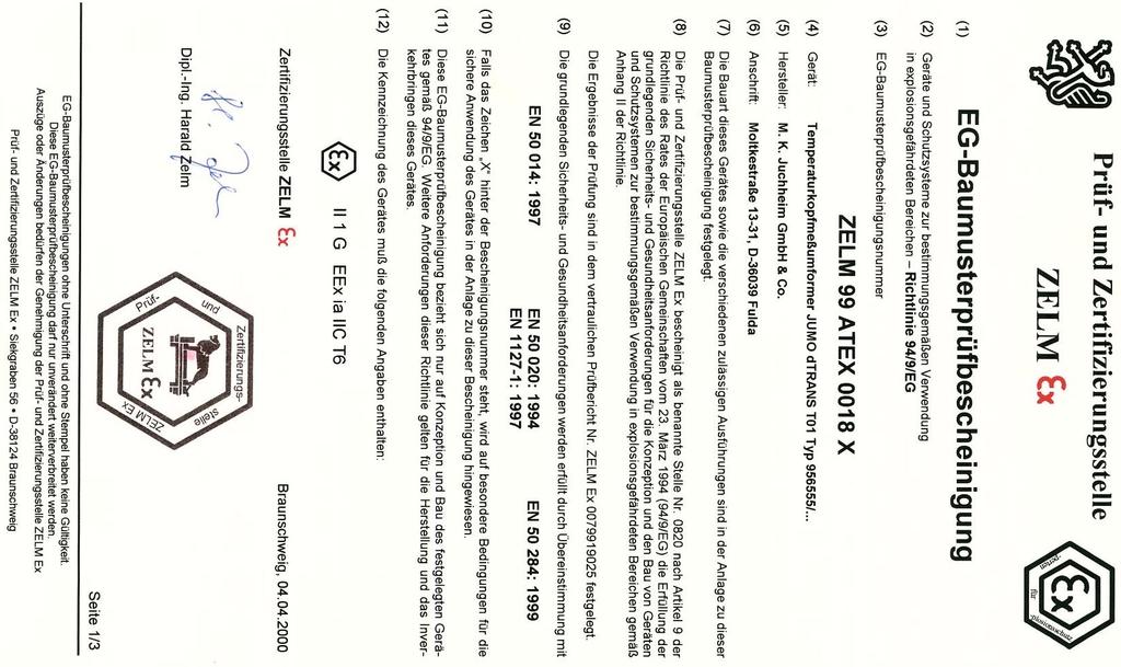
2 Ex-Kennzeichnung Besonderheiten A II 1 G Ex ia IIC T6-T4 Ga Ex ia IIC T6-T4 Ga Die Konformitätserklärung (Seite 14), die Baumusterprüfbescheinigung (Seite 20) und die IECEx-Konformitätsbescheinigung (Seite 29) sind zu beachten. H Der Typ /... entspricht dem Typ /...
3 Zielgruppe 1 Zielgruppe / Normenkonformität Beim JUMO dtrans T01 Typ /... handelt es sich um einen Zweidraht-Messumformer (Temperaturkopfmessumformer). An ihn können Widerstandsthermometer und Thermoelemente angeschlossen werden. Der Einbau erfolgt vorzugsweise in Anschlussköpfen Form B. Normenkonformität Die grundlegenden Sicherheits- und Gesundheitsanforderungen werden erfüllt durch Übereinstimmung mit: - EN : EN : A11: EN : EN : EN : IEC : 2011 (ed. 6) - IEC : 2011 (ed. 6) - IEC :
4 2 Sicherheitshinweise - Die Errichtung und der Betrieb des Temperaturkopfmessumformers muss mit Hilfe dieser Betriebsanleitung und den für sie gültigen Regeln und Normen erfolgen. - Der Temperaturkopfmessumformer kann in Gerätegruppe II Kategorie 1 G (Zone 0), in II 2 G (Zone 1) und in II 3 G (Zone 2) betrieben werden. - Wird der Temperaturkopfmessumformer in II 2 G (Zone 1) oder in II 3 G (Zone 2) betrieben, darf der Sensorstromkreis in II 1 G (Zone 0) eingeführt werden. - Wird der Temperaturkopfmessumformer in II 1 G (Zone 0) betrieben, ist darauf zu achten, dass explosionsfähige Dampf-/Luftgemische nur in atmosphärischen Bedingungen auftreten. Liegen keine explosionsfähigen Gemische vor oder sind Zusatzmaßnahmen gemäß EN getroffen, dürfen die Geräte auch außerhalb der atmosphärischen Bedingungen gemäß ihrer Herstellerspezifikationen betrieben werden. Atmosphärische Bedingungen -20 C Ta +60 C 0,8bar p 1,1bar - Die Konfiguration des Messumformers mit dem PC-Setup-Programm darf nicht im explosionsgefährdeten Bereich erfolgen. - Bei der Konfiguration mit Hilfe eines handelsüblichen Personal Computers (PC) darf die sicherheitstechnische Maximalspannung (U m = 30V) nicht überschritten werden. Ideal ist hierbei die Benutzung eines batteriebetriebenen PC (Notebook). Der Anschluss darf aus sicherheitstechnischen Gründen (Schutz der ex-relevanten Bauelemente) nur zur kurzzeitigen Konfiguration erfolgen. - Der Versorgungsstromkreis muss die Zündschutzart Ex ia IIC erfüllen. - Für Messumformer (Gehäusematerial PC, Vergussmaterial PUR) bzw. Einbauköpfe muss die Verträglichkeit der Gerätematerialien mit den Messstoffen sichergestellt sein. 4
5 2 Sicherheitshinweise - Die Umgebungstemperaturen dürfen die in der nachstehend aufgeführten Tabelle angegebenen Grenzwerte nicht überschreiten. - Der Temperaturkopfmessumformer ist so zu errichten, dass auch für die Anschlussteile ein Schutzgrad von mindestens IP20 gemäß EN erreicht wird. - Bei der Errichtung und dem Betrieb des Temperaturkopfmessumformers ist darauf zu achten, dass keine elektrostatische Aufladung auftreten kann. Auszug aus der EG-Baumusterprüfbescheinigung ZELM 99 ATEX 0018 X Kennzeichnung Temperaturbereich in II 2 G und II 3 G Temperaturbereich in II 1 G Versorgungsstromkreis Höchstwerte an den Klemmen 1(+) und 2(-) innere Induktivität und Kapazität Sensorstromkreis Höchstwerte an den Klemmen 3, 4, 5 und 6 höchstzulässige äußere Induktivität/Kapazität Ex ia IIC Ex ia IIB II 1 G Ex ia IIC T6-T4 Ga T6: Tamb = C T5: Tamb = C T4: Tamb = C T6: Tamb = C T5: Tamb = C T4: Tamb = C Ui = 30VDC Ii = 100mA Pi = 750mW Li = vernachlässigbar klein Ci = vernachlässigbar klein Uo = 9,6VDC Io = 4,5mA Po = 11mW Lo = 4,5mH / Co = 709nF Lo = 8,5mH / Co = 1300nF 5
6 3 Typenerklärung / -schilder JUMO dtrans T01 (1) Grundausführung programmierbarer Zweidraht-Messumformer (2) Eingang (programmierbar) x 888 Werkseitig eingestellt (Pt100 DIN vl) x 999 Konfiguration nach Kundenangaben 1 (3) Ausgang (eingeprägter Gleichstrom - programmierbar) x 888 Werkseitig eingestellt (4 20mA) x 999 Konfiguration nach Kundenangaben (20 4mA) (4) Fühlerbruch/-kurzschluss x 888 Werkseitig eingestellt (positive Sicherung) x 999 Konfiguration nach Kundenangaben (negative Sicherung) (5) Typenzusätze x 000 Keine (1) (2) (3) (4) (5) Bestellschlüssel / - - / Bestellbeispiel / / 000 Serienmäßiges Zubehör - 1 Betriebsanleitung Befestigungsmaterial (2 Befestigungsschrauben, 2 Druckfedern und 2 Sicherungsscheiben) Zubehör - Setup-Programm, mehrsprachig 1. Bei der Konfiguration nach Kundenangaben sind die Fühlerart und der Messbereich im Klartext anzugeben - PC-Interface mit TTL/RS232-Umsetzer und Adapter (Buchse) - PC-Interface mit USB/TTL-Umsetzer, Adapter (Buchse) und Adapter (Stifte) 6
7 3 Typenerklärung / -schilder Die nachfolgende abgebildeten Typenschilder befinden sich auf dem Gehäuse des Messumformers. oder Angabe von Messbereich und Sensor Der F-Nr. (Fabrikations-Nummer) kann das Produktionsdatum (Jahr/ Woche) entnommen werden. Es handelt sich hierbei um die Zeichen 12, 13, 14, 15. Beispiel: F-Nr Der Messumformer wurde demnach in der 3. Woche 2015 produziert. 7
8 - Ex-Kennzeichnung: 4 Technische Daten - EG-Baumusterprüfbescheinigung: ZELM 99 ATEX 0018 X siehe Kapitel 2 Sicherheitshinweise und Kapitel 9 Baumusterprüfbescheinigung - Konformitätserklärung: siehe Kapitel 8 Konformitätserklärung - IECEx-Konformitätsbescheinigung: siehe Kapitel 10 IECEx-Konformitätsbescheinigung - Typenblatt: T II 1 G Ex ia IIC T6-T4 Ga Ex ia IIC T6-T4 Ga 8
9 5 Installation Für das Errichten/Betreiben sind die Vorschriften gemäß ElexV und diese Betriebsanleitung maßgebend. Die maximale Umgebungstemperatur (siehe Kapitel 2 Sicherheitshinweise ) ist unbedingt einzuhalten. Abmessungen 9
10 Anschlussplan 5 Installation Anschluss für Spannungsversorgung DC V bzw. Stromausgang mA Anschlussbelegung +1-2 R B = Bürdenwiderstand U b = Spannungsversorgung Ex-Ausführung nur in Verbindung mit bescheinigtem Ex-Messumformer-Speisegerät! Analoge Eingänge Widerstandsthermometer in Vierleiterschaltung Widerstandsthermometer in Dreileiterschaltung Widerstandsthermometer in Zweileiterschaltung Thermoelement +4-6 U b 8V R B = mA R L 11Ω R L = Leitungswiderstand je Leiter R L 11Ω R L = Leitungswiderstand je Leiter R L 11Ω R L = Leitungswiderstand je Leiter Ex-Ausführung: Anschlussdaten des Ex-Eingangsstromkreises beachten! 10
11 5 Installation Anschlussbeispiel mit Speisegerät/-trenner 11
12 6 Instandhaltung Die für die Wartung/Instandsetzung/Prüfung geltenden Bestimmungen sind einzuhalten. Im Rahmen der Wartung sind vor allem Teile zu prüfen, von denen die Zündschutzart abhängt. Eine Konfiguration des Messumformers über den Setup-Kreis darf niemals im explosionsgefährdeten Bereich erfolgen. Außerhalb des explosionsgefährdeten Bereiches darf der Anschluss aus sicherheitstechnischen Gründen (Schutz der Ex-relevanten Bauelemente) nur zur kurzzeitigen Konfiguration erfolgen. 12
13 7 Setup-Schnittstelle und Feinabgleich Setup-Schnittstelle Die Setup-Schnittstelle dient zur Konfiguration des Messumformers mit Hilfe eines PC. Der Anschluss erfolgt über das PC-Interface mit TTL/RS232-Umsetzer und Adapter. Nach dem Programmieren ist die Verschlussklappe wieder zu schließen. Konfigurierbare Parameter: - TAG-Number (10 Zeichen) - Sensortyp - Anschlussart (2-/3-/4-Leiterschaltung) - externe oder interne Vergleichsstelle - kundenspezifische Linearisierung - Messbereichsgrenzen - Ausgangssignal steigend/fallend (Reversion) - digitales Filter - Verhalten bei Fühlerbruch/-kurzschluss - Nachkalibrierung (Feinabgleich) - Leitungswiderstand bei Zweileiterschaltung Steht kein Ex-Speisegerät (Speisetrenner) zur Verfügung, kann der Zweidraht-Messumformer zur Konfiguration mit Hilfe einer 9V- Blockbatterie versorgt werden. Feinabgleich Unter Feinabgleich ist eine Korrektur des Ausgangssignales zu verstehen. Das Signal kann im Bereich von ± 5% des Endwertes 20mA korrigiert werden. Der Feinabgleich erfolgt mit Hilfe des Setup-Programms. Über das Setup-Programm können der 4-mA-Wert (Nullpunkt), der 20-mA-Wert (Endwert) und eine Offsetverschiebung getrennt abgeglichen werden. 13
14 8 Konformitätserklärung Document No. / Document n. Manufacturer / Etabli par Address / Adresse Product / Produit Name / Nom Type / Type Data sheet no. / N Document d'identification We hereby declare in sole responsibility that the designated product fulfills the requirements of the European Directives. Nous déclare sous notre seule responsabilité que le produit remplit les Directives Européennes. 14
15 8 Konformitätserklärung Directive / Directive Name / Nom Reference / Référence Comment / Remarque Date of first application of the CE mark to the product / Date de 1ère application du sigle sur le produit Standards/Specifications applied / Normes/Spécifications appliquées Reference / Référence Edition / Édition Comment / Remarque Valid for Type / Valable pour le type 15
16 8 Konformitätserklärung Directive / Directive Name / Nom Reference / Référence Comment / Remarque Date of first application of the CE mark to the product / Date de 1ère application du sigle sur le produit Valid for Type / Valable pour le type EU type examination certificate / Certificat d'examen de type UE Reference / Référence Notified Body / Organisme notifié Identification no. / N d'identification Standards/Specifications applied / Normes/Spécifications appliquées Reference / Référence Edition / Édition Comment / Remarque Valid for Type / Valable pour le type 16
17 8 Konformitätserklärung EU type examination certificate / Certificat d'examen de type UE Reference / Référence Notified Body / Organisme notifié Identification no. / N d'identification Standards/Specifications applied / Normes/Spécifications appliquées Reference / Référence Edition / Édition Comment / Remarque Valid for Type / Valable pour le type Recognized quality assurance systems of production / Systèmes de qualité reconnus de production Notified Body / Organisme notifié Identification no. / N d'identification 17
18 8 Konformitätserklärung Directive / Directive Name / Nom Reference / Référence Comment / Remarque Date of first application of the CE mark to the product / Date de 1ère application du sigle sur le produit Standards/Specifications applied / Normes/Spécifications appliquées Reference / Référence Edition / Édition Comment / Remarque Valid for Type / Valable pour le type 18
19 8 Konformitätserklärung Issued by / Etabli par Place, date / Lieu, date Legally binding signatures / Signatures juridiquement valable 19
20 9 Baumusterprüfbescheinigung 20
21 9 Baumusterprüfbescheinigung 21
22 9 Baumusterprüfbescheinigung 22
23 9 Baumusterprüfbescheinigung 23
24 9 Baumusterprüfbescheinigung 24

25 9 Baumusterprüfbescheinigung 25

26 9 Baumusterprüfbescheinigung 26

27 9 Baumusterprüfbescheinigung 27

28 9 Baumusterprüfbescheinigung 28
29 10 IECEx-Konformitätsbescheinigung 29
30 10 IECEx-Konformitätsbescheinigung 30
31 10 IECEx-Konformitätsbescheinigung 31
32 10 IECEx-Konformitätsbescheinigung 32
33
34
35 JUMO dtrans T01 Ex Programmable 2-wire transmitter B Operating Manual V2.00/DE-EN
36 Ex marking Special features A II 1 G Ex ia IIC T6-T4 Ga Ex ia IIC T6-T4 Ga Please note the Declaration of Conformity on page 14, of the Type Examination Certificate on page 20 and of the IECEx Certificate of Conformity on page 29. H Type /... corresponds to type /...
37 1 Application / Conformity with standards Application The JUMO dtrans T01 Type /... is a 2-wire head-mounted temperature transmitter which can be used with resistance thermometers and thermocouples. Preferably, it will be mounted into terminal heads Form B. Conformity with standards Fundamental safety and health requirements are met through the conformity with: - EN : EN : A11: EN : EN : EN : IEC : 2011 (ed. 6) - IEC : 2011 (ed. 6) - IEC :
38 2 Safety notes - The head-mounted temperature transmitter must be set up and operated in accordance with this Operating Manual and the relevant regulations and standards. - The transmitter can be operated in device group II category 1 G (zone 0), in II 2 G (zone 1) and in II 3 G (zone 2). - If the transmitter is operated in II 2 G (zone 1) or in II 3 G (zone 2), the sensor current circuit may be present in II 1 G (zone 0). - If the transmitter is operated in II 1 G (zone 0), care must be taken that inflammable vapor-air mixtures only occur within the atmospheric conditions. If no inflammable mixtures are present, or additional measures according to EN have been taken, the devices may also be operated outside the atmospheric conditions, in accordance with the manufacturer s specifications. Atmospheric conditions -20 C Ta +60 C 0.8bar p 1.1bar - The transmitter must not be configured within the hazardous area using the PC setup program. - When configuring with the aid of a standard PC, the maximum safe voltage (U m = 30V) must not be exceeded. The use of a battery-operated PC (notebook) is ideal. For safety reasons (protection of Ex-relevant components), the connection must only be made briefly, for configuration. - The supply circuit must conform to the explosion protection Ex ia IIC. - For transmitters (case material PC, encapsulated material PUR) or mounting heads, it must be ensured that the device materials are compatible with the measured media. 4
39 2 Safety notes - The ambient temperatures must not exceed the limit values specified in the table below. - The transmitter must be set up in such a way as to provide at least IP20 protection according to EN 60529, also for the connecting parts. - During setting up and operation of the transmitter, any build-up of electrostatic charge must be avoided. Extract from the EC Type Examination Certificate ZELM99ATEX0018X Marking Temperature range in II 2 G and II 3 G Temperature range in II 1 G Supply circuit maximum values at terminals 1(+) and 2(-) internal inductance and capacitance Sensor current circuit maximum values at terminals 3, 4, 5 and 6 max. permissible external inductance/capacitance Ex ia IIC Ex ia IIB II 1 G Ex ia IIC T6-T4 Ga T6: T amb = -40 to +55 C T5: T amb = -40 to +70 C T4: T amb = -40 to +75 C T6: T amb = -40 to +40 C T5: T amb = -40 to +50 C T4: T amb = -40 to +60 C U i = 30VDC I i = 100mA P i = 750mW L i = negligible C i = negligible U o = 9.6VDC I o = 4.5mA P o = 11mW L o = 4.5mH / C o = 709nF L o = 8.5mH / C o = 1300nF 5
40 3 Type designation/labels JUMO dtrans T01 (1) Basic version programmable 2-wire transmitter (2) Input (programmable) x 888 factory-set (Pt100 DIN vl) x 999 custom configuration 1 (3) Output (proportional DC current - programmable) x 888 factory-set (4 20mA) x 999 custom configuration (20 4mA) (4) Probe break/short-circuit x 888 factory-set (positive protection) x 999 custom configuration (negative protection) (5) Extra codes x 000 none (1) (2) (3) (4) (5) Order code / - - / Order example / / 000 Standard accessories - 1 Operating Manual fixing items (2 fastening screws, 2 compression springs, and 2locking washers) Accessories - Setup program, multilingual 1. For custom configuration, probe type and range have to be specified in plain text - PC interface with TTL/RS232 converter and adapter (sockets) - PC interface with USB/TTL converter, adapter (sockets) and adapter (pins) 6
41 3 Type designation/labels The labels shown below are attached to the transmitter housing. or specification of range and sensor The serial No. (F-Nr.) indicates the production date (year/week). The figures concerned are in position 12, 13, 14, 15. Example: F-Nr This shows that the transmitter was manufactured in 2015, week 3. 7
42 -Ex marking: 4 Technical data - EC type examination certificate: ZELM 99 ATEX 0018 X see Chapter 2 Safety notes and Chapter 9 Type Examination Certificate - Declaration of Conformity: see Chapter 8 Declaration of Conformity - IECEx Certificate of Conformity: see Chapter 10 IECEx Certificate of Conformity - Data Sheet: T II 1 G Ex ia IIC T6-T4 Ga Ex ia IIC T6-T4 Ga 8
43 5 Installation The regulations according to ElexV and this Operating Manual apply when setting up and operating the transmitter. It is imperative to observe the maximum ambient temperature (see Chapter 2 Safety notes ). Dimensions 9
44 Connection diagram 5 Installation Connection for Supply 8 30V DC or current output 4 20mA Terminals +1-2 R B = burden resistance U b = supply Ex version only in combination with a certified Ex transmitter supply unit! Analog inputs Resistance thermometer in 4-wire circuit Resistance thermometer in 3-wire circuit Resistance thermometer in 2-wire circuit Thermocouple +4-6 U b 8V R B = mA R L 11Ω R L = lead resistance per conductor R L 11Ω R L = lead resistance per conductor R L 11Ω R L = lead resistance per conductor Ex version: please note the connection data for the Ex input circuit! 10
45 5 Installation Example of connection with supply unit/isolator 11
46 6 Maintenance The appropriate regulations concerning maintenance, repair and testing must be observed. In particular, all parts on which explosion protection depends must be checked during maintenance. The transmitter must never be configured inside the hazardous area via the setup circuit. For safety reasons (protection of Ex-relevant components), the connection outside the hazardous area may only be made for the purpose of brief configuration. 12
47 Setup interface 7 Setup interface and fine calibration The setup interface is available for configuring the transmitter from a PC. The connection is via the PC interface with a TTL/RS232 converter and adapter. The cover flap must be closed after programming. Configurable parameters: - tag number (10 characters) -sensor type - connection circuit (2-/3-/4-wire) - external or internal cold junction - custom linearization -range limits - output signal rising/falling (inversion) - digital filter - response to probe break/short-circuit - recalibration (fine calibration) - lead resistance for 2-wire circuit If no Ex supply unit (supply isolator) is available, the 2-wire transmitter can also be configured using a 9V block battery. Fine calibration Fine calibration means adjustment of the output signal. The signal can be adjusted within ± 5% of the 20mA end value. Fine calibration is performed using the setup program. Values for 4 ma (zero point), 20 ma (full scale) and offset can be calibrated separately, using the setup program. 13
48 8 Declaration of Conformity Document No. / Document n. Manufacturer / Etabli par Address / Adresse Product / Produit Name / Nom Type / Type Data sheet no. / N Document d'identification We hereby declare in sole responsibility that the designated product fulfills the requirements of the European Directives. Nous déclare sous notre seule responsabilité que le produit remplit les Directives Européennes. 14
49 8 Declaration of Conformity Directive / Directive Name / Nom Reference / Référence Comment / Remarque Date of first application of the CE mark to the product / Date de 1ère application du sigle sur le produit Standards/Specifications applied / Normes/Spécifications appliquées Reference / Référence Edition / Édition Comment / Remarque Valid for Type / Valable pour le type 15
50 8 Declaration of Conformity Directive / Directive Name / Nom Reference / Référence Comment / Remarque Date of first application of the CE mark to the product / Date de 1ère application du sigle sur le produit Valid for Type / Valable pour le type EU type examination certificate / Certificat d'examen de type UE Reference / Référence Notified Body / Organisme notifié Identification no. / N d'identification Standards/Specifications applied / Normes/Spécifications appliquées Reference / Référence Edition / Édition Comment / Remarque Valid for Type / Valable pour le type 16
51 8 Declaration of Conformity EU type examination certificate / Certificat d'examen de type UE Reference / Référence Notified Body / Organisme notifié Identification no. / N d'identification Standards/Specifications applied / Normes/Spécifications appliquées Reference / Référence Edition / Édition Comment / Remarque Valid for Type / Valable pour le type Recognized quality assurance systems of production / Systèmes de qualité reconnus de production Notified Body / Organisme notifié Identification no. / N d'identification 17
52 8 Declaration of Conformity Directive / Directive Name / Nom Reference / Référence Comment / Remarque Date of first application of the CE mark to the product / Date de 1ère application du sigle sur le produit Standards/Specifications applied / Normes/Spécifications appliquées Reference / Référence Edition / Édition Comment / Remarque Valid for Type / Valable pour le type 18
53 8 Declaration of Conformity Issued by / Etabli par Place, date / Lieu, date Legally binding signatures / Signatures juridiquement valable 19

54 9 Type Examination Certificate 20
55 9 Type Examination Certificate 21
56 9 Type Examination Certificate 22
57 9 Type Examination Certificate 23
58 9 Type Examination Certificate 24

59 9 Type Examination Certificate 25

60 9 Type Examination Certificate 26

61 9 Type Examination Certificate 27

62 9 Type Examination Certificate 28
63 10 IECEx Certificate of Conformity 29
64 10 IECEx Certificate of Conformity 30
65 10 IECEx Certificate of Conformity 31
66 10 IECEx Certificate of Conformity 32
67
68 JUMO GmbH & Co. KG JUMO Instrument Co. Ltd. JUMO Process Control, Inc. Street address: Moritz-Juchheim-Straße Fulda, Germany JUMO House Temple Bank, Riverway Harlow, Essex, CM20 2DY, UK 6733 Myers Road East Syracuse, NY 13057, USA Delivery address: Phone: Phone: Mackenrodtstraße 14 Fax: Fax: Fulda, Germany sales@jumo.co.uk info.us@jumo.net Postal address: Fulda, Germany Internet: Internet: Phone: Fax: mail@jumo.net Internet:
JUMO dtrans T01 Junior
 JUMO dtrans T01 Junior Programmierbarer Zweidraht-Messumformer Programmable 2-wire transmitter B 707014.0 Betriebsanleitung Operating Manual 2013-01-08/00590122 Typenerklärung JUMO dtrans T01 Junior (1)
B Betriebsanleitung Operating Instructions 09.05/ Programmierbarer Zweidraht-Messumformer Programmable 2-wire transmitter
 dtrans T01 707010/... dtrans T01 T 707012/... JdTRANS T01 Programmierbarer Zweidraht-Messumformer Programmable 2-wire transmitter B 70.7010.0 Betriebsanleitung Operating Instructions 09.05/00365406 Typenerklärung
JUMO dtrans T01 Ex. Programmierbarer Zweidraht-Messumformer Programmable 2-wire transmitter. B Betriebsanleitung Operating Manual
 JUMO dtrans T01 Ex Programmierbarer Zweidraht-Messumformer Programmable 2-wire transmitter B 707015.0 Betriebsanleitung Operating Manual V1.00/DE-EN/00365407 Ex-Kennzeichnung Besonderheiten A II 1 G Ex
JUMO dtrans T01 HART. Programmierbarer Zweidraht-Messumformer Programmable 2-wire transmitter. B Betriebsanleitung Operating Manual
 JUMO dtrans T01 HART Programmierbarer Zweidraht-Messumformer Programmable 2-wire transmitter B 707016.0 Betriebsanleitung Operating Manual V2.00/DE-EN/00392000 Besonderheiten II 1 G Ex ia IIC T6/T5/T4
B 707015.0 Betriebsanleitung Operating Instructions 2012-06-29/00365407
 JUMO dtrans T01 Programmierbarer Zweidraht-Messumformer Programmable 2-wire transmitter B 707015.0 Betriebsanleitung Operating Instructions 2012-06-29/00365407 Besonderheiten II 1 G Ex ia IIC T6 A Die
Messumformer- Speisegerät Supply unit for transmitters. B Betriebsanleitung Operating Instructions 03.07/
 Messumformer- Speisegerät Supply unit for transmitters B 70.7520.0 Betriebsanleitung Operating Instructions 03.07/00359391 Besonderheiten II (1) G D [EEx ia] IIC oder [EEx ia] IIB II (2) G D [EEx ib] IIC
JUMO dtrans T01 HART. Programmierbarer Zweidraht-Messumformer Programmable 2-wire transmitter. B Betriebsanleitung Operating Manual
 JUMO dtrans T01 HART Programmierbarer Zweidraht-Messumformer Programmable 2-wire transmitter B 707016.0 Betriebsanleitung Operating Manual V1.00/DE-EN/00392000 Besonderheiten II 1 G Ex ia IIC T6/T5/T4
JUMO dtrans T01 Programmierbarer Zweidraht-Messumformer
 M. K. JCHHEIM GmbH & Co Telefon: (06 61) 60 03-7 25 Hausadresse: Moltkestraße 13-31, 36039 Fulda, Germany Telefax: (06 61) 60 03-6 81 Lieferadresse: Mackenrodtstraße 14, 36039 Fulda, Germany E-Mail: mail@jumo.net
Messumformer-Speisegerät
 JUMO GmbH & Co. KG Telefon: 49 661 6003-727 Hausadresse: Moritz-Juchheim-Straße 1, 36039 Fulda, Germany Telefax: 49 661 6003-508 Lieferadresse: Mackenrodtstraße 14, 36039 Fulda, Germany E-Mail: mail@jumo.net
B Betriebsanleitung Operating Instructions / TT x
 TT956530/... TT956531/... TT956533/... TT956532/... TT956534/... TT 95.653x Analoger Messumformer mit digitaler Einstellung Analog transmitter with digital adjustment B 95.6530 Betriebsanleitung Operating
ma/hart-two-wire ma/hart-four-wire Profibus PA Foundation Fieldbus Modbus PLICSMOBILE. Document ID: 43634
 EU-Konformitätserklärung EU declaration of conformity Déclaration UE de conformité 61 62 63 65 66 67 68 4... 20 ma/hart-two-wire 4... 20 ma/hart-four-wire Profibus PA Foundation Fieldbus Modbus PLICSMOBILE
HW 2.0.0, SW ma/hart-two-wire ma/hart-four-wire Profibus PA Foundation Fieldbus Modbus PLICSMOBILE. Document ID: 43634
 EU-Konformitätserklärung EU declaration of conformity Déclaration UE de conformité VEGAPULS 61 VEGAPULS 62 VEGAPULS 63 VEGAPULS 65 VEGAPULS 66 VEGAPULS 67 VEGAPULS 68 VEGAPULS SR68 HW 2.0.0, SW 4.0.0 4...
Ex-Barriere für Diagnoseeinheit SITRANS DA400 / Ex-barrier for diagnostics unit SITRANS DA400 7MJ2010-1AA 0032
 Ex-Barriere für Diagnoseeinheit SITRANS DA400 / Ex-barrier for diagnostics unit SITRANS DA400 7MJ2010-1AA 0032 Warnung Elektrischer Anschluss in explosionsgefährdeten Bereichen Anschluss und Inbetriebnahme
B Betriebsanleitung Operating Instructions 12.05/
 dtrans T01 707011/... dtrans T01 T 707013/... J dtrans T01 HART Programmierbarer Zweidraht-Messumformer Programmable 2-wire transmitter B 70.7011.0 Betriebsanleitung Operating Instructions 12.05/00387995
Electrical tests on Bosch unit injectors
 Valid for Bosch unit injectors with order numbers 0 414 700 / 0 414 701 / 0 414 702 Parts Kit Magnet*: - F00H.N37.925 - F00H.N37.933 - F00H.N37.934 * For allocation to the 10-place Bosch order number,
J dtrans T02j Programmierbarer Messumformer Programmable transmitter. B Betriebsanleitung Operating Instructions 08.
 J dtrans T02j Programmierbarer Messumformer Programmable transmitter B 95.6520 Betriebsanleitung Operating Instructions 08.01/00384945 JUMO dtrans T02j Serienmäßiges Zubehör - 1 Betriebsanleitung B 95.6520
VDE Prüf- und Zertifizierungsinstitut Zeichengenehmigung
 2 Dieses Blatt gilt nur in Verbindung mit Blatt 1 des sausweises Nr. This supplement is only valid in conjunction with 1 of the. Schaltschrank-Heizelement Switch cabinet heating element mit Lüfter with
Electrical testing of Bosch common rail piezo injectors
 Applies to generation CRI 3: Bosch 10-position order number 0 445 115 = CRI 3-16 (CRI 3.0) 1600 bar 0 445 116 = CRI 3-18 (CRI 3.2) 1800 bar 0 445 117 = CRI 3-20 (CRI 3.3) 2000 bar Tools required: Hybrid
J dtrans T02j Programmierbarer Messumformer Programmable transmitter. B Betriebsanleitung Operating Instructions 03.
 J dtrans T02j Programmierbarer Messumformer Programmable transmitter B 70.7020.0 Betriebsanleitung Operating Instructions 03.07/00384945 JUMO dtrans T02j Serienmäßiges Zubehör 1 Typenerklärung (1) Grundausführung
HEAG 151, 152, 153, 154 Digital Converter
 Montage- und Betriebsanleitung Installation and operating instructions MB095-11055704 Baumer_HEAG151-152-153-154_II_DE-EN (16A1) HEAG 151, 152, 153, 154 Digital Converter 1-2 Allgemeine Hinweise - Funktionsweise
Kalibrierschein Kalibrierzeichen Calibration Certificate Calibration mark
 Alexander Wiegand SE & Co. KG akkreditiert durch die / accredited by the Deutsche Akkreditierungsstelle GmbH als Kalibrierlaboratorium im / as calibration laboratory in the Deutschen Kalibrierdienst Kalibrierschein
Certificate of conformity Generating unit, NS-protection
 Applicant: Product: Certificate of conformity Generating unit, NS-protection Schneider Electric Solar Inverters USA, Inc. 250 South Vasco Road Livermore, California 94551 USA Photovoltaic Inverter with
Bedienungsanleitung (Einbau- und Anschlusshinweise)
") Temperaturmeßtechnik Geraberg GmbH Bedienungsanleitung (Einbau- und Anschlusshinweise) Widerstandsthermometer System V...g staubgeschützte und erhöht sichere Temperaturfühler mit einfachem Kabelabgang
Temperaturmeßtechnik Geraberg GmbH Bedienungsanleitung (Einbau- und Anschlusshinweise) Widerstandsthermometer System V...g staubgeschützte und erhöht sichere Temperaturfühler mit einfachem Kabelabgang
JUMO dtrans T02 Programmierbarer Vierdraht-Messumformer (Smart Transmitter)
") JUMO GmbH & Co. KG Telefon: +49 661 6003-727 Hausadresse: Moritz-Juchheim-Straße 1, 36039 Fulda, Germany Telefax: +49 661 6003-508 Lieferadresse: Mackenrodtstraße 14, 36039 Fulda, Germany E-Mail: mail@jumo.net
JUMO GmbH & Co. KG Telefon: +49 661 6003-727 Hausadresse: Moritz-Juchheim-Straße 1, 36039 Fulda, Germany Telefax: +49 661 6003-508 Lieferadresse: Mackenrodtstraße 14, 36039 Fulda, Germany E-Mail: mail@jumo.net
Electrical testing of Bosch common rail solenoid valve (MV) injectors
 injectors") Applies to MV injector, generation: -CRI 1.0 / 2.0 / 2.1 / 2.2 -CRIN 1 / 2 / 3, with K oder AK plug Bosch 10-position order number Bosch-Bestellnummer CRI: 0 445 110 xxx Bosch-Bestellnummer CRIN: 0 445
Applies to MV injector, generation: -CRI 1.0 / 2.0 / 2.1 / 2.2 -CRIN 1 / 2 / 3, with K oder AK plug Bosch 10-position order number Bosch-Bestellnummer CRI: 0 445 110 xxx Bosch-Bestellnummer CRIN: 0 445
Electrical testing of Bosch common rail Injectors
 Electrical testing of Bosch common rail Injectors Contents: 1. Adapter cable for Hybridtester FSA 050 (article number 0 684 010 050 / 1 687 023 571) 2. Electrical testing of Bosch common rail solenoid
The enclosure of the module provides a degree of protection IP20 according to EN
 (13) SCHEDULE (14) to EC-Type Examination Certificate DEKRA 12ATEX0232 X Issue No. 2 (15) Description Digital Output Module (DOM) Type 9475/3*-**-**, for operation in the Remote I/O Systems IS1 and IS1+.
VDE Prüf- und Zertifizierungsinstitut Zeichengenehmigung
 Blatt / page 2 Dieses Blatt gilt nur in Verbindung mit Blatt 1 des sausweises Nr.. This supplement is only valid in conjunction with page 1 of the. Terrestrische Photovoltaik-Module mit Silizium-Solarzellen
VDE Prüf- und Zertifizierungsinstitut Gutachten mit Fertigungsüberwachung
 Blatt / page 2 Dieses Blatt gilt nur in Verbindung mit Blatt 1 des Gutachtens mit Fertigungsüberwachung Nr.. surveillance No.. USV-Zubehör UPS-Accessories Typ(en) / Type(s): A) PDM35xxIEC-yyy B) PDM13xxIEC-yyy
VDE Prüf- und Zertifizierungsinstitut Zeichengenehmigung
 Blatt / page 2 Dieses Blatt gilt nur in Verbindung mit Blatt 1 des sausweises Nr.. This supplement is only valid in conjunction with page 1 of the. Terrestrische Photovoltaik-Module mit Silizium-Solarzellen
VDE Prüf- und Zertifizierungsinstitut Zeichengenehmigung
 Blatt / page 2 Dieses Blatt gilt nur in Verbindung mit Blatt 1 des sausweises Nr.. This supplement is only valid in conjunction with page 1 of the. Netzgerät für IT-Geräte Power supply for IT-Equipment
/10
 04.2015 1/10 04.2015 2/10 04.2015 3/10 04.2015 4/10 04.2015 5/10 04.2015 6/10 SCHRAMM GMBH. POSTFACH 62 01 22. 60350 FRANKFURT AM MAIN EX Betriebsanleitung Typ WME, TME, MW08, MT08. FLINSCHSTRASSE 18a
VDE Prüf- und Zertifizierungsinstitut Zeichengenehmigung
 Blatt / page 2 Dieses Blatt gilt nur in Verbindung mit Blatt 1 des sausweises Nr.. This supplement is only valid in conjunction with page 1 of the. Espresso-Kaffeebereiter mit Mühle Espresso coffee maker
VDE Prüf- und Zertifizierungsinstitut Zeichengenehmigung
 Blatt / page 2 Dieses Blatt gilt nur in Verbindung mit Blatt 1 des sausweises Nr.. This supplement is only valid in conjunction with page 1 of the. Netzgerät für IT-Geräte Power supply for IT-Equipment
VDE Prüf- und Zertifizierungsinstitut Zeichengenehmigung
 Blatt / Page 2 Dieses Blatt gilt nur in Verbindung mit Blatt 1 des sausweises Nr.. This supplement is only valid in conjunction with page 1 of the. DEHNrail M Typ(en) / Type(s) DR M 2P 30; DR M 2P 30 FM
ZU Endlagenschalter, elektrisch für WA 131 / 131 H Limit Switch, Electrical, for WA 131 / 131 H.
 ZU 0859 Endlagenschalter, elektrisch für WA 131 / 131 H Limit Switch, Electrical, for WA 131 / 131 H www.knick.de Bauart und Funktion Der Endlagenschalter ZU 0859 wandelt die pneumatischen Endlagen signale,
VDE Prüf- und Zertifizierungsinstitut Zeichengenehmigung
 Blatt / page 2 Dieses Blatt gilt nur in Verbindung mit Blatt 1 des sausweises Nr.. This supplement is only valid in conjunction with page 1 of the. Terrestrische Photovoltaik-Module mit Silizium-Solarzellen
Certificate of conformity Generating unit, NS-protection
 Certificate of conformity Generating unit, NS-protection Applicant: Product: Schneider Electric Solar Inverters USA, Inc. 250 South Vasco Road Livermore, California 94551 USA Photovoltaic Inverter with
VDE Prüf- und Zertifizierungsinstitut Gutachten mit Fertigungsüberwachung
 Blatt / page 2 Dieses Blatt gilt nur in Verbindung mit Blatt 1 des Gutachtens mit Fertigungsüberwachung Nr.. surveillance No.. Netzteil für IT-Geräte / DC/DC-Wandler Power supply for IT-Equipment / DC/DC-Converter
JUMO dtrans T02 Ex. Programmierbarer Messumformer Programmable transmitter. B Betriebsanleitung Operating Manual V2.
 JUMO dtrans T02 Ex Programmierbarer Messumformer Programmable transmitter B 707025.0 Betriebsanleitung Operating Manual V2.00/DE-EN/00396221 Ex-Kennzeichnung Besonderheiten II (1) G [Ex ia Ga] IIC II (1)
JUMO dtrans T04 Vierdraht-Messumformer mit Einstellung über DIP-Schalter/PC-Setup-Programm
 JUMO GmbH & Co. KG Telefon: +49 661 6003-727 Hausadresse: Moritz-Juchheim-Straße 1, 36039 Fulda, Germany Telefax: +49 661 6003-508 Lieferadresse: Mackenrodtstraße 14, 36039 Fulda, Germany E-Mail: mail@jumo.net
VDE Prüf- und Zertifizierungsinstitut Zeichengenehmigung
 Blatt / page 2 Dieses Blatt gilt nur in Verbindung mit Blatt 1 des sausweises Nr.. This supplement is only valid in conjunction with page 1 of the. PV-Wechselrichter mit selbsttätiger Freischaltstelle
VDE Prüf- und Zertifizierungsinstitut Zeichengenehmigung
 2 Dieses Blatt gilt nur in Verbindung mit Blatt 1 des sausweises Nr.. This supplement is only valid in conjunction with 1 of the. PV-Wechselrichter mit selbsttätiger Freischaltstelle Power converter for
VDE Prüf- und Zertifizierungsinstitut Zeichengenehmigung
 Blatt / page 2 Dieses Blatt gilt nur in Verbindung mit Blatt 1 des sausweises Nr. This supplement is only valid in conjunction with page 1 of the. DEHNbloc MAXI, DEHNbloc, DEHNgap Typ(en) / Type(s): DB
Bedienungsanleitung (Einbau- und Anschlusshinweise)
") Temperaturmeßtechnik Geraberg GmbH Bedienungsanleitung (Einbau- und Anschlusshinweise) Widerstandsthermometer System V...s Widerstandsthermometer für Temperaturen bis 150 C Gerätegruppe : II Gerätekategorie
Temperaturmeßtechnik Geraberg GmbH Bedienungsanleitung (Einbau- und Anschlusshinweise) Widerstandsthermometer System V...s Widerstandsthermometer für Temperaturen bis 150 C Gerätegruppe : II Gerätekategorie
VDE Prüf- und Zertifizierungsinstitut Zeichengenehmigung
 Blatt / page 2 Dieses Blatt gilt nur in Verbindung mit Blatt 1 des sausweises Nr.. This supplement is only valid in conjunction with page 1 of the. PV-Wechselrichter mit selbsttätiger Freischaltstelle
VDE Prüf- und Zertifizierungsinstitut Zeichengenehmigung
 VDE Prüf- und Zertifizierungsinstitut Zeichengenehmigung Ausweis-Nr. / Certificate No. 40040851 Blatt / Page 2 Name und Sitz des Genehmigungs-Inhabers / Name and registered seat of the Certificate holder
EU-Baumusterprüfbescheinigungen EU-Type Examination Certificate
 EU-Baumusterprüfbescheinigungen EU-Type Examination Certificate der Notifizierten Stelle über die Konformitätsbewertung nach ANHANG III der gemäß Richtlinie für Funkanlagen 2014/53/EU of the Notified Body
Betriebsanleitung (Sicherheitsrelevanter Teil ATEX und IECEx) Induktive Sensoren NAMUR NN504A NN505A /00 02/2014
 Induktive Sensoren NAMUR NN504A NN505A /00 02/2014") Betriebsanleitung (Sicherheitsrelevanter Teil ATEX und IECEx) Induktive Sensoren NAMUR NN504A NN505A 80001940/00 02/2014 Hinweise für den sicheren Einsatz in explosionsgefährdeten Bereichen Bestimmungsgemäße
Betriebsanleitung (Sicherheitsrelevanter Teil ATEX und IECEx) Induktive Sensoren NAMUR NN504A NN505A 80001940/00 02/2014 Hinweise für den sicheren Einsatz in explosionsgefährdeten Bereichen Bestimmungsgemäße
JUMO dtrans T04 Vierdraht-Messumformer mit Einstellung über DIP-Schalter/PC-Setup-Programm
 JUMO GmbH & Co. KG Telefon: +49 661 6003-727 Hausadresse: Moltkestraße 13-31, 36039 Fulda, Germany Telefax: +49 661 6003-508 Lieferadresse: Mackenrodtstraße 14, 36039 Fulda, Germany E-Mail: mail@jumo.net
VDE Prüf- und Zertifizierungsinstitut Zeichengenehmigung
 Blatt / page 2 Dieses Blatt gilt nur in Verbindung mit Blatt 1 des sausweises Nr. This supplement is only valid in conjunction with page 1 of the. Luftreiniger Air cleaner Typ(en) / Type(s): a) Nice-R
VDE Prüf- und Zertifizierungsinstitut Zeichengenehmigung
 Blatt / Page 2 Dieses Blatt gilt nur in Verbindung mit Blatt 1 des sausweises Nr.. This supplement is only valid in conjunction with page 1 of the. bwasserpumpe Sanitary pump Typ(en) / Type(s) a) GENIX
Datenblatt. Remote-I/O - u-remote UR20-4AO-UI or 4-wire connection; 16-bit resolution; 4 outputs
 2- or 4-wire connection; 16-bit resolution; 4 outputs The analogue output module controls up to 4 analogue actuators with +/-10 V, +/-5 V, 0...10 V, 0...5 V, 2...10 V, 1...5 V, 0...20 ma or 4...20 ma with
VDE Prüf- und Zertifizierungsinstitut Zeichengenehmigung
 Blatt / Page 2 Dieses Blatt gilt nur in Verbindung mit Blatt 1 des sausweises Nr.. This supplement is only valid in conjunction with page 1 of the. Überspannungsschutzgerät Surge protective device V20-...
VDE Prüf- und Zertifizierungsinstitut Zeichengenehmigung
 2 Dieses Blatt gilt nur in Verbindung mit Blatt 1 des sausweises Nr.. This supplement is only valid in conjunction with page 1 of the. PV-Wechselrichter mit selbsttätiger Freischaltstelle Power converter
VDE Prüf- und Zertifizierungsinstitut Zeichengenehmigung
 Blatt / page 2 Dieses Blatt gilt nur in Verbindung mit Blatt 1 des sausweises Nr. This supplement is only valid in conjunction with page 1 of the. Unterbrechungsfreie Stromversorgung Uninterruptible power
Circuit Sensor type Model designation EC-type exami- WIKA- (s. Ex-certific.) Fa. Pepperl & Fuchs nation certificate Model
 Fa. Pepperl & Fuchs nation certificate Model") 4. Alarm contacts The permissible limits for U i, I i and P i of the intrinsically safe supply circuits depend on the sensor type. They can be taken from the corresponding EC-type examination certificates.
4. Alarm contacts The permissible limits for U i, I i and P i of the intrinsically safe supply circuits depend on the sensor type. They can be taken from the corresponding EC-type examination certificates.
Datenblatt. P-series PDU 2.5/4/4AN
 Turn five into three that's the winning formula of the new P series with the PUSH IN connection system in which the pitches for 2.5, 4, 6 and 10 mm² are each combined in one terminal block. That means
Hazards and measures against hazards by implementation of safe pneumatic circuits
 Application of EN ISO 13849-1 in electro-pneumatic control systems Hazards and measures against hazards by implementation of safe pneumatic circuits These examples of switching circuits are offered free
VDE Prüf- und Zertifizierungsinstitut Zeichengenehmigung
 Blatt / page 2 Dieses Blatt gilt nur in Verbindung mit Blatt 1 des sausweises Nr.. This supplement is only valid in conjunction with page 1 of the. Geräteschalter Switch for appliances Typ(en) / Type(s):
VDE Prüf- und Zertifizierungsinstitut Gutachten mit Fertigungsüberwachung
 Blatt / page 2 Dieses Blatt gilt nur in Verbindung mit Blatt 1 des Gutachtens mit Fertigungsüberwachung Nr.. surveillance No.. Silikon-Fassungsader, wärmebeständig Silicone wire, heat-resistant Typ(en)
VDE Prüf- und Zertifizierungsinstitut Zeichengenehmigung
 Blatt / Page 2 Dieses Blatt gilt nur in Verbindung mit Blatt 1 des sausweises Nr.. This supplement is only valid in conjunction with page 1 of the. Mehrfachsteckdose, ortsveränderlich Socket-outlet, multiple
VDE Prüf- und Zertifizierungsinstitut Zeichengenehmigung
 Blatt / page 2 Dieses Blatt gilt nur in Verbindung mit Blatt 1 des sausweises Nr. This supplement is only valid in conjunction with page 1 of the. Elektronischer Schalter, Zeitschalter Electronic switch,
VDE Prüf- und Zertifizierungsinstitut Zeichengenehmigung
 Blatt / page 2 Dieses Blatt gilt nur in Verbindung mit Blatt 1 des sausweises Nr.. This supplement is only valid in conjunction with page 1 of the. Netzgerät für IT-Geräte Power supply for IT-Equipment
EG-Konformitätserklärung
 EG-Konformitätserklärung Dokument Nr.: GL-11/22/24/08 Hiermit erklären wir, die Firma in alleiniger Verantwortung die Konformität der Produktreihe Servoverstärker SERVOSTAR 300 mit folgenden einschlägigen
Lufft UMB Sensor Overview
 Lufft Sensor Overview Wind Radiance (solar radiation) Titan Ventus WS310 Platinum WS301/303 Gold V200A WS300 WS400 WS304 Professional WS200 WS401 WS302 Radiance (solar radiation) Radiation 2 Channel EPANDER
VDE Prüf- und Zertifizierungsinstitut Gutachten mit Fertigungsüberwachung
 Blatt / Page 2 Dieses Blatt gilt nur in Verbindung mit Blatt 1 des Gutachtens mit Fertigungsüberwachung Nr... Netzteil für IT-Geräte / DC/DC-Wandler Power supply for IT-Equipment / DC/DC-Converter Typ(en)
DGR CE SICHERHEITSVENTILE PED CE SAFETY VALVES
 DGR CE SICHERHEITSVENTILE PED CE SAFETY VALVES Ecksicherheitsventile aus Rotguss mit Nirofeder Typ 606 GF/GFL/tGF für neutrale Flüssigkeiten,Dampf und gasförmige Medien Safety valves made of red brass
EU-Konformitätserklärung
 EU-Konformitätserklärung EU Declaration of Conformity System 100V / 04.2016 Hersteller: Manufacturer: VIPA GmbH Anschrift: Ohmstraße 4 Address: 91074 Herzogenaurach Germany Produktfamilie: System 100V
2. Nachtrag. (Ergänzung gemäß Richtlinie 94/9/EG Anhang III Ziffer 6) zur EG-Baumusterprüfbescheinigung DMT 03 ATEX E 048
 zur EG-Baumusterprüfbescheinigung DMT 03 ATEX E 048")
PROFIBUS-DP Repeater 1 to 1 and 1 to 5 with optional level converter module
 LSS PROFIBUS-DP Repeater 1 to 1 and 1 to 5 with optional level converter module The LSS PROFIBUS-DP repeaters 1 to 1 and 1 to 5 are used for coupling up to six PROFIBUS bus segments in RS 485 bus technology.
!#$"&)%%#' (
%%#' (") CE Kennzeichnung CE Marking 1/5/d/e Hersteller: Manufacturer: Anschrift: Address: Produkte: Products: Weidmüller Interface GmbH & Co. KG Klingenbergstrasse 16, D - 32758 Detmold P.O. Box 3030, D - 32720
CE Kennzeichnung CE Marking 1/5/d/e Hersteller: Manufacturer: Anschrift: Address: Produkte: Products: Weidmüller Interface GmbH & Co. KG Klingenbergstrasse 16, D - 32758 Detmold P.O. Box 3030, D - 32720
VDE Prüf- und Zertifizierungsinstitut Zeichengenehmigung
 VDE Prüf- und Zertifizierungsinstitut Zeichengenehmigung Ausweis-Nr. / Certificate No. 40026348 Blatt / page 2 Name und Sitz des Genehmigungs-Inhabers / Name andregistered seat of the Certificate holder
ZEICHENGENEHMIGUNG MARKS APPROVAL
 ZEICHENGENEHMIGUNG MRKS PPROVL OSRM GmbH Marcel-Breuer-Str. 6 80807 München ist berechtigt, für ihr Produkt / is authorized to use for their product Vorschaltgerät, elektronisch Electronic ballast die
VDE Prüf- und Zertifizierungsinstitut Zeichengenehmigung
 Blatt / Page 2 Dieses Blatt gilt nur in Verbindung mit Blatt 1 des sausweises Nr.. This supplement is only valid in conjunction with page 1 of the. Unterbrechungsfreie Stromversorgung Uninterruptible power
Einsteck-Widerstandsthermometer mit Anschlusskopf Form B
 Typenblatt 90.2120 (90.2102) Seite 1/5 mit Anschlusskopf Form B Für Temperaturen von -50... +600 C Mit auswechselbarem Messeinsatz Als Einfach- und Doppel-Widerstandsthermometer Anschlusskopf Form B, BUZ,
VDE Prüf- und Zertifizierungsinstitut Gutachten mit Fertigungsüberwachung
 Blatt / Page 2 Dieses Blatt gilt nur in Verbindung mit Blatt 1 des Gutachtens mit Fertigungsüberwachung Nr.. This supplement is only valid in conjunction with page 1 of the Certificate of Conformity with
VDE Prüf- und Zertifizierungsinstitut Zeichengenehmigung
 Blatt / page 2 Dieses Blatt gilt nur in Verbindung mit Blatt 1 des sausweises Nr. This supplement is only valid in conjunction with page 1 of the. Terrestrische Photovoltaik-Module mit Silizium-Solarzellen
VDE Prüf- und Zertifizierungsinstitut Zeichengenehmigung
 usweis-nr. / Blatt / Page 2 Bimed Teknik letler San. ve Tic..S., S. S. Bakir ve Pirinc San. Sitesi, Leylak Cad. No.15 Beylikdüzü, 34520 Dieses Blatt gilt nur in Verbindung mit Blatt 1 des sausweises Nr..
VDE Prüf- und Zertifizierungsinstitut Zeichengenehmigung
 Blatt / page 2 Dieses Blatt gilt nur in Verbindung mit Blatt 1 des sausweises Nr.. This supplement is only valid in conjunction with page 1 of the. Geräteschalter Switch for appliances Typ(en) / Type(s):
 TúYTIOÐ 2.ERGANZUNG zur Besche nigungsnummer: Gerät: Hersteller Anschrift. Auftragsnummer: Ausstellungsdatum TUV 04 ATEX 2531 Messu mformer Typ KFD2-WAC2-Ex1* Pepperl + Fuchs GmbH Lilienthalstrasse 200
LOC Pharma. Anlage. Lieferantenfragebogen Supplier Questionnaire. 9. Is the warehouse temperature controlled or air-conditioned?
 Please complete this questionnaire and return to: z.h. Leiter Qualitätsmanagement info@loc-pharma.de Name and position of person completing the questionnaire Signature Date 1. Name of Company 2. Address
VDE Prüf- und Zertifizierungsinstitut Zeichengenehmigung
 Blatt / Page 2 Dieses Blatt gilt nur in Verbindung mit Blatt 1 des sausweises Nr.. This supplement is only valid in conjunction with page 1 of the. Datenverarbeitungsgerät Information Technology Equipment
VDE Prüf- und Zertifizierungsinstitut Zeichengenehmigung
 usweis-nr. / Blatt / Page 2 Dieses Blatt gilt nur in Verbindung mit Blatt 1 des sausweises Nr.. This supplement is only valid in conjunction with page 1 of the. Terrestrische Photovoltaik-Module mit Silizium-Solarzellen
Einschraub-Widerstandsthermometer mit Anschlusskopf Form B
 Typenblatt 902020 Seite 1/6 mit Anschlusskopf Form B Für Temperaturen von -50... +600 C Mit auswechselbarem Messeinsatz Als Einfach- und Doppel-Widerstandsthermometer Anschlusskopf Form B, BUZ, BUZH, BBK
Zusatz zur Betriebsanleitung Addendum to the Operating Instructions
 Drive Technology \ Drive Automation \ System Integration \ Services Zusatz zur Betriebsanleitung Addendum to the Operating Instructions Austausch von MOVIGEAR -S01 durch MOVIGEAR -DSC-B Replacing MOVIGEAR
VDE Prüf- und Zertifizierungsinstitut Zeichengenehmigung
 Blatt / Page 2 Dieses Blatt gilt nur in Verbindung mit Blatt 1 des sausweises Nr.. This supplement is only valid in conjunction with page 1 of the. Unterbrechungsfreie Stromversorgung Uninterruptible power
Steckplatz. Steckplatz 1 Steckplatz 1. Steckplatz 2. Steckplatz 2. Steckplatz 3. Steckplatz 2. Steckplatz 3
 SIPART DR Ergänzungsblatt / Supplement sheet Beschaltung und Einstellung der Optionskarten zu SIPART DR Reglern - 6DR2800-8P Pt100 Eingang (RTD) - 6DR2800-8T Thermoelement Eingang (TC) zu den Handbüchern:
VDE Prüf- und Zertifizierungsinstitut Zeichengenehmigung
 Blatt / Page 2 Dieses Blatt gilt nur in Verbindung mit Blatt 1 des sausweises Nr.. This supplement is only valid in conjunction with page 1 of the. PV-Wechselrichter mit selbsttätiger Freischaltstelle
VDE Prüf- und Zertifizierungsinstitut Zeichengenehmigung
 Blatt / Page 2 Dieses Blatt gilt nur in Verbindung mit Blatt 1 des sausweises Nr.. This supplement is only valid in conjunction with page 1 of the. Leitungsschutzschalter Circuit-breaker Serie / series
VDE Prüf- und Zertifizierungsinstitut Zeichengenehmigung
 Blatt / Page 2 Dieses Blatt gilt nur in Verbindung mit Blatt 1 des sausweises Nr.. This supplement is only valid in conjunction with page 1 of the. Installationssteckdose, Haushalt Installation socket-outlet
ATEX II (1) G [Ex ia] IIC CE 0123 TPS 03 ATEX Instructions
![ATEX II (1) G [Ex ia] IIC CE 0123 TPS 03 ATEX Instructions](/thumbs/55/37136893.jpg "ATEX II (1) G [Ex ia] IIC CE 0123 TPS 03 ATEX Instructions") Qualität zertifiziert nach ISO 9001. Postfach 1106, D71301 Waiblingen Esslinger Str. 26, WN-Hegnach Tel. 07151/956230 Fax 07151/956250 E-mail: info@braun-tacho.de Internet: www.braun-tacho.de Isolating
Qualität zertifiziert nach ISO 9001. Postfach 1106, D71301 Waiblingen Esslinger Str. 26, WN-Hegnach Tel. 07151/956230 Fax 07151/956250 E-mail: info@braun-tacho.de Internet: www.braun-tacho.de Isolating
JX3-PS1. Installationsanleitung. Version Lieferumfang
 JX3-PS1 Spannungsversorgungsmodul Jetter AG Kontakte: Gräterstraße 2 E-Mail - Vertrieb: sales@jetter.de D-71642 Ludwigsburg E-Mail - Hotline: hotline@jetter.de Germany Telefon - Hotline: +49(0)7141/2550-444
VDE Prüf- und Zertifizierungsinstitut Zeichengenehmigung
 Blatt / Page 2 Dieses Blatt gilt nur in Verbindung mit Blatt 1 des sausweises Nr.. This supplement is only valid in conjunction with page 1 of the. Leitungsschutzschalter Circuit-breaker ic60h; ic60n Typ(en)
VDE Prüf- und Zertifizierungsinstitut Zeichengenehmigung
 2 Dieses Blatt gilt nur in Verbindung mit Blatt 1 des sausweises Nr. This supplement is only valid in conjunction with 1 of the. Vorschaltgerät, elektronisch Electronic ballast Typ(en) / Type(s): 01) PCA
VDE Prüf- und Zertifizierungsinstitut Zeichengenehmigung
 VDE Prüf- und Zertifizierungsinstitut Zeichengenehmigung Ausweis-Nr. / Certificate No. 40024802 Blatt / Page 2 Name und Sitz des Genehmigungs-Inhabers / Name and registered seat of the Certificate holder
VDE Prüf- und Zertifizierungsinstitut Zeichengenehmigung
 Blatt / Page 2 Dieses Blatt gilt nur in Verbindung mit Blatt 1 des sausweises Nr.. This supplement is only valid in conjunction with page 1 of the. Überspannungsschutzgerät Surge protective device DEHNshield
 EG-Konformitätserklärung EC-Declaration of Conformity CE-Déclaration de Conformité Wir (we; nous) R. STAHL Schaltgeräte GmbH, Am Bahnhof 30, D-74638 Waldenburg 9160/..-1.-11 erklären in alleiniger Verantwortung,
VDE Prüf- und Zertifizierungsinstitut Zeichengenehmigung
 Blatt / page 2 Dieses Blatt gilt nur in Verbindung mit Blatt 1 des sausweises Nr. This supplement is only valid in conjunction with page 1 of the. Installationsschalter Installation switch Typ(en) / Type(s):