Radialkolbenpumpen Radial Piston Pumps
|
|
|
- Gisela Albrecht
- vor 8 Jahren
- Abrufe
Transkript
1 Radialkolbenpumpen Radial Piston Pumps
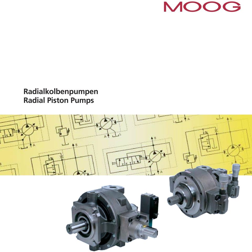
2 RADIALKOLBENPUMPEN RADIAL PISTON PUMP Druckregler 2 Hubring 3 Leckölanschluß 4 Gehäuse 5 SAE-Leitungsanschlüsse 6 Gleitschuhe 7 Buntmetallfrei geführter Kolben 8 Wälzlager 9 Kupplung 1 Pressure compensator 2 Stroke ring 3 Drain port 4 Body 5 SAE piping connections 6 Slipper pads 7 Pistons without non-ferrous metal guides 8 Rolling bearing 9 Coupling 2 Moog

3 RADIALKOLBENPUMPEN RADIAL PISTON PUMP INHALT SEITE CONTENTS PAGE Allgemeines Wirkungsweise Typenschlüssel Auswahlreihe Kenngrößen Verstellbereich Kennlinien Regler Mehrfachtechnik Pumpengehäuse Antriebsflansche Regler Pumpengehäuse 140 Antriebsflansche 140 Regler 140 Zahnradpumpen für Anbau an Dämpfungsflansch Steuerblöcke für Technische Hinweise Ersatzteile Auswahlreihe General Mode of operation Model Code Selection Specifications Adjustment range Performance curves Controller Multiple arrangements Pump housings Drive flanges Compensators Pump housings 140 Drive flanges 140 Compensators 140 Gear pumps mounting on Anti-vibration flange Control blocks for Technical information Selection of spare parts Moog 3

4 RADIALKOLBENPUMPEN RADIAL PISTON PUMP ALLGEMEINES Die Moog-Radialkolbenpumpe steht für Zuverlässigkeit, geringes Geräusch und lange Lebensdauer. Dies wird unterstrichen durch die erhöhte Gewährleistung. Diese beträgt unter den auf Seite 12 genannten Randbedingungen für Mineralöl Betriebsstunden oder 24 Monate (je nachdem, was zuerst erreicht wird). Das vorhandene Baukastensystem erlaubt die Auswahl einer auf die jeweilige Anwendung individuell zugeschnittenen Pumpe bzw. Pumpenkombination. Zur Verfügung stehen: Mitteldruckserie ( bar) und Hochdruckserie (350 bar) für Mineralöl Sieben Baugrößen zwischen 19 und 140 cm 3 /U Große Auswahl an Reglern, mechanischen, hydraulischen und elektrohydraulischen (analog oder digital mit CAN Bus) Mechanische Förderstrombegrenzung Mehrfachpumpen durch axialen Anbau (bis zu 5 Pumpen möglich) Verschiedene Antriebsflansche Eignung für verschiedene Hydrauliköle wie Mineralöl, Getriebeöl, biologisch abbaubares Öl Eignung für Sonderflüssigkeiten wie Öl in Wasser (HFA), Wasserglycol (HFC), synthetische Ester (HFD), Bohremulsion, Isocyanat und Polyol (siehe Spezialkatalog) GENERAL The Moog Radial Piston Pump stands for reliability, low noise and durability. This is underlined by its extended warranty. Under the conditions described on page 13, warranty for mineral oil is covered for 10,000 operating hours or 24 month, whichever occurs first. The modular nature of the system enables the selection of individually tailor-made pumps or pump combinations to suit the application in question. The following features are available: Medium pressure series ( bar) and high pressure series (350 bar) for mineral oil. Seven sizes between 19 and 140 cm 3 /rev Large selection of controls, mechanically, hydraulically and electric-hydraulically (analog or digital with CAN Bus) Mechanical flow limitation Multiple pumps by axial mounting (up to 5 pumps possible) Various mounting flanges Suitable for various hydraulic oils like mineral oil, transmission oil, bio-degradable oil Suitable for special fluids such as oil in water (HFA), water-glycol (HFC), synthetical ester (HFD), cutting emulsion, isocyanate and polyol (see special catalog) Weitere Vorteile der Moog - Radialkolbenpumpe sind: Niederer Geräuschpegel Kurze Stellzeiten Kompakte Bauweise Gutes Ansaugverhalten Geringe Druckpulsation Further advantages of the Moog Radial Piston Pump are: Low noise level Rapid response time Compact design Good suction characteristics. Low pressure ripple 4 Moog

5 RADIALKOLBENPUMPEN RADIAL PISTON PUMP WIRKUNGSWEISE Das Antriebsmoment wird von der Welle (1) über eine Kreuzscheibenkupplung (2) querkraftfrei auf den Zylinderstern (3), der auf dem Steuerzapfen (4) gelagert ist, übertragen. Die radial im Zylinderstern angeordneten Kolben (5) stützen sich über hydrostatisch entlastete Gleitschuhe (6) im Hubring (7) ab. Kolben und Gleitschuh sind über ein Kugelgelenk miteinander verbunden und durch einen Ring gefesselt. Die Gleitschuhe werden durch zwei übergreifende Ringe (8) im Hubring geführt und im Betrieb durch Fliehkraft und Öldruck an den Hubring gedrückt. Bei Rotation des Zylindersterns führen die Kolben infolge der exzentrischen Lage des Hubringes eine Hubbewegung aus, die dem doppelten Wert der Exzentrizität entspricht. Die Exzentrizität wird durch zwei im Pumpengehäuse gegenüberliegende Stellkolben (9, 10) verändert. Der Ölstrom wird über Kanäle in Gehäuse und Steuerzapfen zu- und abgeführt. Gesteuert wird dies mittels Saug- und Druckschlitz im Steuerzapfen. Die Abstützung der in der Pumpe auftretenden Druckkräfte erfolgt auf hydrostatisch nahezu vollständig entlasteten Flächen. Das Wälzlager der Antriebswelle wird nur durch äußere Kräfte belastet. MODE OF OPERATION The shaft (1) transfers the drive torque to the star-shaped cylinder block (3) free from any transverse forces via a cross-disc coupling (2). The cylinder block is supported on the control journal (4). The radial pistons (5) in the cylinder block abut against the stroke ring (7) through hydrostatically balanced slipper pads (6). Piston and slipper pad are joined by a ball and socket joint which is locked by a ring. The slipper pads are guided in the stroke ring by two overlapping rings (8) and, when running, are forced against the stroke ring by centrifugal force and oil pressure. As the cylinder block rotates, the pistons perform a reciprocating motion due to the eccentric position of the stroke ring, the piston stroke being twice the eccentricity. The eccentric position of the stroke ring can be altered by means of two diametrically opposed control pistons (9, 10) in the pump body. The oil flow to and from the pump passes through ducts in the body and control journal, and is controlled by the suction and delivery ports in the latter. The pressure forces generated inside the pump are absorbed by surfaces which are almost fully hydrostatically balanced. The rolling bearing supporting the drive shaft is subjected to external forces only. Moog 5
 im Hubring geführt und im Betrieb durch Fliehkraft und Öldruck an den Hubring gedrückt.")
6 TYPENSCHLÜSSEL MODEL CODE DER TYPENSCHLÜSSEL BESCHREIBT DIE OPTIONEN DER PUMPE THE MODEL CODE DESCRIBES OPTIONS OF THE PUMP Definiert werden konstruktive Schnittstellen (Flansch, Wellenende und Anschlüsse), hydraulische Kenngrößen (Fördervolumen, Betriebsdruck und Hydraulikfluid) sowie Regler bzw. Steuerungsprinzip. There are design interfaces (flange, shaft end and ports), hydraulic parameters (volume flow, operating pressure and hydraulic fluid) and control principle (open and closed loop). BEISPIEL EXAMPLE Position Nr. (Antrieb) Antrieb Pumpe 1 Pumpe 2 Pumpe 3 Pumpe 4 Pumpe 5 Position Nr. (Pumpe) Item No. (drive) Drive Pump 1 Pump 2 Pump 3 Pump 4 Pump 5 Item No. (pump) R R Z 6 P P P 7 2 R V V N B S S B M M M J G F 13 Z Z Z Pos Sym R L 15 A Antrieb Kennzahl Radialkolbenpumpe Drehrichtung Auf Antrieb gesehen rechts Auf Antrieb gesehen links Drehzahl max. Drehzahl z.b. n = 1450 min Antriebswelle Passfeder nach DIN 6885 Drive Codes No Radial Piston Pump Rotation Clockwise, looking at drive shaft Counter-clockwise, looking at drive shaft Speed max. speed e.g. n = 1450 min Drive shaft Key to DIN 6885 A1* A7 B C Evolventenverzahnung nach DIN 5482 für B1 bzw. DIN 5480 für B7 (bei - und ZGS- Anbau obligatorisch) Passfeder nach SAE-744 C Involute spline DIN 5482 for B1 or DIN 5480 for B7 (obligatory with multiple arrangement of and ZGS) Key to SAE-744 C B1* C3 B7 5 D 1 3 Evolventenverzahnung nach SAE 744 C (bei - und ZGS-Anbau obligatorisch) Lagerung/ Anbauflansch Normale Lagerung; metrischer Rundflansch Standard-Lagerung 2/4-Loch SAE-Flansch nach DIN ISO 3019/1 (zöllig) Involute spline to SAE 744 C (obligatory with multiple arrangement of and ZGS) Bearing arrangement/ Mounting flange Standard bearing arrangement, metric round flange Standard bearing arrangement, 2/4 hole SAE flange according to DIN ISO 3019/1 (imperial dimensions) D3 7 Standard-Lagerung 4-Loch ISO-Flansch nach DIN ISO 3019/2 (metrisch) Standard bearing arrangement, 4 hole ISO flange according to DIN ISO 3019/2 (metric dimensions) Fettgedruckte Positionen sind bevorzugt lieferbar. Items in bold-face type are preferred delivery items. Nicht lieferbar V = 140 cm 3 /U nicht als A1 und B1 lieferbar.* Not available V = 140 cm 3 /rev not available as A1 or B1.* 6 Moog
 Antrieb Pumpe 1 Pumpe 2 Pumpe 3 Pumpe 4 Pumpe 5 Position Nr. (Pumpe) Item No. (drive) Drive Pump 1 Pump 2 Pump 3 Pump 4 Pump 5 Item No.")
7 TYPENSCHLÜSSEL MODEL CODE Pos Sym. R P V S H S/H M A B C D E J P 28 Radialkolbenpumpe Arbeitsprinzip Radialkolbenprinzip Betriebsart Pumpenbetrieb Bauart Verstellpumpe Fördervolumen 19 cm 3 /U 32 cm 3 /U 45 cm 3 /U 63 cm 3 /U 80 cm 3 /U 90 cm 3 /U (nur mit Leistungsregler S) 100 cm 3 /U 140 cm 3 /U Pumpenanschlüsse Saug- und Druckanschluss gleich, in Standardausführung (SAE 3000 psi) mit metrischem Gewinde, bis bar Saug- und Druckanschluss gleich, in Hochdruckausführung (SAE 6000 psi) mit metrischem Gewinde, bis 350 bar 1 ) Sauganschluß mit Flansch SAE 3000 psi nur Druckanschluß mit Flansch SAE 6000 psi 90, 100, 140 Betriebsflüssigkeit Mineralöl, Getriebeöl, biologisch abbaubares Öl HFA (Öl in Wasser) HFB (Öl in Wasser) HFC (Wasserglycol) HFD (Synthetisches Ester) Bohremulsion Isocyanat Polyol Betriebsdruck Max. Betriebsdruck z.b. p = bar 28 Programm siehe Katalog " für Sonderflüssigkeiten" Radial Piston Pump Operating principle Radial piston principle Mode of operation Pump Type of construction Variable displacement pump (open circuit) Displacement 19 cm 3 /rev 32 cm 3 /rev 45 cm 3 /rev 63 cm 3 /rev 80 cm 3 /rev 90 cm 3 /rev (only with constant horse power control S) 100 cm 3 /rev 140 cm 3 /rev Pump ports Suction and pressure port equal, in standard pressure type (SAE 3000 psi) with metric thread, up to bar Suction and pressure port equal, in high pressure type (SAE 6000 psi) with metric thread, up to 350 bar 1 ) Suction connection with flange SAE 3000 psi only Pressure connection with flange SAE 6000 psi 90, 100, 140 Operating fluid Mineral oil, transmission oil, bio-degradable oil HFA (oil in water) HFB (oil in water) HFC (water-glycol) HFD (synthetic ester) Cutting emulsion Isocyanate Polyol Operating pressure Max. operating pressure e.g. p = bar 28 For programme see Catalogue " for special fluids" Fettgedruckte Positionen sind bevorzugt lieferbar. Items in bold-face type are preferred delivery items. 1 )nur 19, 32, 63 und 80 1 ) 19, 32, 63 and 80 only Moog 7
 mit metrischem Gewinde, bis 350 bar 1 ) Sauganschluß mit Flansch SAE 3000 psi nur Druckanschluß mit Flansch SAE")
8 TYPENSCHLÜSSEL MODEL CODE Pos Sym. A B C F G H J R S T V Z Y X U * bis to 45 Radialkolbenpumpe Steuerung/Regler Handrad (für Polyurethanverschäumung) Mech. Hubeinstellung (V = const.) Servosteuerung (offener Kreis) Druckregler, einstellbar Druckregler, abschliessbar Druckregler, hydraulisch ansteuerbar Kombinierter Druck-Förderstromregler Kombinierter Druck- Förderstromregler mit P-T Steuerkante Leistungsregler (System Kraftvergleich) Elektrohydr. Verstellung mit analoger Ansteuerung Elektrhydr. Verstellung mit on-bord-elektronik und digitaler Ansteuerung Zusatzeinrichtung ohne Zusatzeinrichtung Begrenz. max. Förderstrom Mit Mooring-Regelung Druck- und Förderstrombegrenzung, hydraulisch angesteuert Zusatzangabe (auszufüllen bei F, G, J, S, T, V ) Druckregler einstellbar F und abschliessbar G bar bar Komb. Druck- Förderstromregler J p am Regler 10 bar 20 bar Leistungsregler S P1 [kw] n = 1450 min cm 3 63 cm 3 90 cm ,5 5 7, Radial Piston Pump Control Handwheel (for polyurethane foam manufacturing) Mech. stroke adjustment (V = const.) Servo control (open circuit) Adjustable pressure compensator Pressure compensator lockable Remote pressure compensator Combined pressure flow compensator (load sensing) Combined pressure flow compensator with P-T control notch Constant horse-power control (Force comparison system) Electric-hydraulic control with analog interface Electric-hydraulic control with build-in electronic and digital interface Accessories no accessories Limiting of max. flow With Mooring control Remote pressure and flow control Additional information (fill in for F, G, J, S, T, V ) Pressure compensator adjustable F and lockable G bar bar Comb. pressure-flow compensator J p on compensator 10 bar 20 bar Constant horse-power control S 18, V [cm 3 ] AZ BZ CZ FZ FY GZ GY HZ HY HX 100 JZ JY RZ SZ TZ VZ RY SY TY VY SU * * * * * * 1 2 Elektrohydr. Verstellung T, V Ansteuerung durch Eigendruck Ansteuerung durch Fremddruck 1) 1) nicht zulässig mit " Begrenzung max. Förderstr. Y " Electric- hydraulic control T, V Actuation by means of internal pressure Actuation by means of external pressure 1) 1) not to use with " limiting of max. flows. Y " Nicht lieferbar Not available 8 Moog
 Elektrohydr. Verstellung mit analoger Ansteuerung Elektrhydr.")
9 TYPENSCHLÜSSEL MODEL CODE Pos Sym. Z P N B M C 18 F G Z 00 Zahnradpumpe Arbeitsprinzip Zahnradprinzip Betriebsart Pumpenbetrieb Bauart Buchsenbauart, Normalausführung Fördervolumen Baugrösse F 4 cm 3 /U 5,5 cm 3 /U 8 cm 3 /U 11 cm 3 /U 16 cm 3 /U 19 cm 3 /U 22,5 cm 3 /U Baugrösse G" 32 cm 3 /U 45 cm 3 /U Gehäuseausführung Leitungsanschluss Bosch Betriebsflüssigkeit Mineralöl HFC (nur für Baugrösse F ) Betriebsdruck Max. Betriebsdruck, z.b. p = 175 bar 18 Baugrösse Baugrösse F Baugrösse G Zusatzeinrichtung ohne Zusatzeinrichtung Zusatzangabe ohne Zusatzangabe Anbau an 32 bis 140 Gear pump Operating principle Gear wheel principle Mode of operation Pump Type of construction Bushes-type, standard version Displacement Size F 4 cm 3 /rev 5,5 cm 3 /rev 8 cm 3 /rev 11 cm 3 /rev 16 cm 3 /rev 19 cm 3 /rev 22,5 cm 3 /rev Size G" 32 cm 3 /rev 45 cm 3 /rev Housing version Bosch line connection Operating fluid Mineral oil HFC (size F only) Operating pressure Max. operating pressure, e.g. p = 175 bar 18 Size Size F Size G Accessories No accessories Additional information No additional information Mounting on 32 to 140 Fettgedruckte Positionen sind bevorzugt lieferbar. Items in bold-face type are preferred delivery items. Moog 9

10 ISO FLANSCH UND WELLENENDE (METRISCH) ISO FLANGE AND SHAFT END (METRIC) AUSWAHLREIHE Standardausführung ( bar) Einzelpumpe, Rechtslauf metrisch SELECTION Standard version ( bar) Single pump, clockwise rotation metric V [cm 3 U / ] rev p [bar] Regler Control Bestellformel Code Bestellnummer Ordering code Druckregler, einstellbar Adjustable pressure compensator Druckregler, hydraulisch ansteuerbar Remote pressure compensator Kombinierter Druck- und Förderstromregler Combined pressure and flow compensator Elektrohydraulische Verstellung Electric-hydraulic control 0514 R 15 A 1 R P V 19 S M 28 F Z R 15 A 1 R P V 32 S M 28 F Z R 15 A 1 R P V 45 S M 28 F Z R 15 A 1 R P V 63 S M 28 F Z R 15 A 1 R P V 80 S M 28 F Z R 15 A 1 R P V 100 S/H M 28 F Z R 15 A 1 R P V 19 S M 28 H Z 0514 R 15 A 1 R P V 32 S M 28 H Z 0514 R 15 A 1 R P V 45 S M 28 H Z 0514 R 15 A 1 R P V 63 S M 28 H Z 0514 R 15 A 1 R P V 80 S M 28 H Z 0514 R 15 A 1 R P V 100 S/H M 28 H Z 0514 R 15 A 1 R P V 19 S M 28 J Z 0514 R 15 A 1 R P V 32 S M 28 J Z 0514 R 15 A 1 R P V 45 S M 28 J Z 0514 R 15 A 1 R P V 63 S M 28 J Z 0514 R 15 A 1 R P V 80 S M 28 J Z 0514 R 15 A 1 R P V 100 S/H M 28 J Z 0514 R 15 A 7 R P V 140 S/H M 28 R Z 0514 R 15 A 1 R P V 19 S M 28 T Z R 15 A 1 R P V 32 S M 28 T Z R 15 A 1 R P V 45 S M 28 T Z R 15 A 1 R P V 63 S M 28 T Z R 15 A 1 R P V 80 S M 28 T Z R 15 A 1 R P V 100 S/H M 28 T Z R 15 A 7 R P V 140 S/H M 28 T Z Moog

11 SAE FLANSCH UND WELLENENDE (INCH) SAE FLANGE AND SHAFT END (INCH) AUSWAHLREIHE Standardausführung ( bar) Einzelpumpe, Rechtslauf inch SELECTION Standard version ( bar) Single pump, clockwise rotation inch V [cm 3 U / ] rev p [bar] Regler Control Bestellformel Code Bestellnummer Ordering code Druckregler, einstellbar Adjustable pressure compensator Druckregler, hydraulisch ansteuerbar Remote pressure compensator Kombinierter Druck- und Förderstromregler Combined pressure and flow compensator Elektrohydraulische Verstellung Electric-hydraulic control 0514 R 18 C 3 R P V 19 S M 28 F Z R 18 C 3 R P V 32 S M 28 F Z R 18 C 3 R P V 45 S M 28 F Z R 18 C 3 R P V 63 S M 28 F Z R 18 C 3 R P V 80 S M 28 F Z R 18 C 3 R P V 100 S/H M 28 F Z R 18 C 3 R P V 19 S M 28 H Z 0514 R 18 C 3 R P V 32 S M 28 H Z 0514 R 18 C 3 R P V 45 S M 28 H Z 0514 R 18 C 3 R P V 63 S M 28 H Z 0514 R 18 C 3 R P V 80 S M 28 H Z 0514 R 18 C 3 R P V 100 S/H M 28 H Z 0514 R 18 C 3 R P V 19 S M 28 J Z 0514 R 18 C 3 R P V 32 S M 28 J Z 0514 R 18 C 3 R P V 45 S M 28 J Z 0514 R 18 C 3 R P V 63 S M 28 J Z 0514 R 18 C 3 R P V 80 S M 28 J Z 0514 R 18 C 3 R P V 100 S/H M 28 J Z 0514 R 18 C 3 R P V 140 S/H M 28 R Z 0514 R 18 C 3 R P V 19 S M 28 T Z R 18 C 3 R P V 32 S M 28 T Z R 18 C 3 R P V 45 S M 28 T Z R 18 C 3 R P V 63 S M 28 T Z R 18 C 3 R P V 80 S M 28 T Z R 18 C 3 R P V 100 S/H M 28 T Z R 18 C 3 R P V 140 S/H M 28 T Z Moog 11

12 TECHNISCHE DATEN TECHNICAL DATA Kenngrössen Fördervolumen [cm 3 /U] Bauart Befestigungsart Einbaulage Masse [kg] Massenträgheitsmoment [kg cm 2 ] Leitungsanschluss Standardausführung "S" SAE 3000 psi Hochdruckausführung "H" SAE 6000 psi Empfohlener Rohraussendurchmesser für Leckstromleitungen (leichte Baureihe) [mm] Leckstromabführung Antriebsart Umgebungstemperaturbereich Max. Drehzahl bei Eingangsdruck 0,8 bar abs. [min -1 ] Max. Drehzahl bei Eingangsdruck 1 bar abs. [min -1 ] Höchstdrehzahl für geräuscharmen Lauf [min -1 ] Min. Eingangsdruck Sauganschluss Max. Gehäusedruck Standard- Dauerdruck ausführung Höchstdruck 1 ) [bar] "S" Druckspitze Hochdruck- Dauerdruck ausführung Höchstdruck 1 ) [bar] "H" Druckspitze Druckflüssigkeit Druckflüssigkeitstemperaturbereich Viskosität Filterung 1 ) Höchstdruck nach DIN Pumpe für offenen Kreis mit verschiedenen Verstell- und Regeleinrichtungen 1. Stirnbefestigung, Zentrier- und Lochkreisdurchmesser nach DIN/ISO 3019/2 (metrisch) 2. Anbauflansch nach DIN/ISO 3019/1 (Zollabmessungen) 3. Anbauflansch nach DIN/ISO 3019/2 (metrisch) beliebig 22 17,7 3 /4 3 / ,8 bar (absolut) 2 bar (1 bar Überdruck) ) ) , ) ) , ) ) ,3 1 1 /4 1 1 / ) ) ,3 1 1 /4 (Gehäuse wie 100) ) ) ,3 1 1 /2 (Saug) 1 1 /4 (Druck) SAE 6000 psi Mineralöl nach DIN C bis +80 C Zulässiger Betriebsbereich 12 bis 100 mm 2 /s empfohlener Betriebsbereich 16 bis 46 mm 2 /s Druckflüssigkeit der Viskositätsklasse ISO VG 46 oder VG 32 max. Viskosität 500 mm 2 /s während des Anlaufs mit Elektromotor 1800 min -1 max. Viskosität 800 mm 2 /s während des Anlaufs mit Verbrennungsmotor NAS 1638, Klasse 9; ISO/DIS 4406, Klasse 18/15 Zu erreichen mit Filterfeinheit 20 = 75 2 ) ) ) ,3 1 1 /2 (Saug) 1 1 /4 (Druck) SAE 6000 psi ) ) ,0 2 1 /2 (Saug) 1 1 /2 (Druck) SAE 6000 psi Die Leckstromabführung ist so zu verlegen, dass das Pumpengehäuse stets vollständig mit Druckflüssigkeit gefüllt ist. Der Druck am Leckstromanschluss darf 2 bar absolut (1 bar Überdruck) nicht überschreiten. Leitungsende unterhalb des Flüssigkeitsspiegels. Kein Filter und kein Rückschlagventil in die Leckstromleitung. Direktantrieb mit Kupplung (bei anderer Antriebsart bitte Rücksprache) -15 C bis +60 C ) ) 2 ) Rückhalterate für Schmutzteilchen > 20 µm ist 1: 75, d.h. 98,67 % 3 ) Bei Pumpen mit elektrohydraulischer Verstellung: Höchstdruck 300 bar/druckspitze 330 bar? Warnung Inbetriebnahme der Pumpen muß durch entsprechend ausgebildetes Fachpersonal erfolgen. Die Öltemperatur im Tank darf die Temperatur der Pumpe nicht mehr als 25 C übersteigen. Ist dies der Fall, so darf die Pumpe bis zur Erwärmung nur in kurzen Intervallen von ca. 1-2 Sekunden eingeschaltet werden. 12 Moog
![Drehzahl bei Eingangsdruck 0,8 bar abs. [min -1 ] Max. Drehzahl bei Eingangsdruck 1 bar abs. [min -1 ] Höchstdrehzahl für geräuscharmen Lauf [min -1 ] Min. Eingangsdruck Sauganschluss Max.](/docs-images/40/11853603/images/page_12.jpg "Gehäusedruck Standard- Dauerdruck ausführung Höchstdruck 1 ) [bar] \"S\" Druckspitze Hochdruck- Dauerdruck ausführung Höchstdruck 1 ) [bar] \"H\" Druckspitze Druckflüssigkeit")
13 TECHNISCHE DATEN TECHNICAL DATA Specifications Displacement [cm 3 /rev] Type of construction Type of mounting Mounting position Weight [kg] (lbs) Mass moment of inertia [kg cm 2 ](lb in cm 2 ) Line connection Standard version "S" SAE 3000 psi High-pressure version "H" SAE 6000 psi Recommended pipe OD for drain lines (lightweight version) [mm] (in) Drain Type of drive Ambient temperature range Max. speed at inlet pressure 0,8 bar (11 psi) abs. [min -1 ] Max. speed at inlet pressure 1 bar (14 psi) abs. [min -1 ] Maximum speed for silent running [min -1 ] Min. inlet pressure suction connection Max. housing pressure Standard- continuous pressure version max. pressure 1 ) [bar] "S" pressure peak 4 ) High pressure continuous pressure version max. pressure 1 ) [bar] "H" pressure peak 4 ) Hydraulic fluid Hydraulic fluid temperature range Viscosity Filtering 1 ) Max. pressure to DIN ) Dirt particles retention rate > 20 µm is 1: 75, i.e. 98,67 % 3 ) Pumps with electric-hydraulic control: max. pressure 300 bar/pressure peak 330 bar 4 ) bar = 4000 psi; 350 bar = 5000 psi; 420 bar = 6000 psi Pump for open circuit with various control devices 1. End mounting, centering and hole-circle dia. to DIN/ISO 3019/2 (metric) 2. Mounting flange to DIN/ISO 3019/1 (Inch) 3. Mounting flange to DIN/ISO 3019/2 (metric) optional 22 (48) 17,7 (0,016) 3 /4 3 /4 15 (5/8) 33 (73) 61,0 (0,054) (3/4) ) ) (73) 61,0 (0,054) 1 18 (3/4) ) ) (143) 186,3 (0,165) 1 1 /4 1 1 /4 22 (7/8) ) ) (143) 186,3 (0,165) 1 1 /4 (housing like 100) 22 (7/8) ) ) (156) 186,3 (0,165) 1 1 /2 (suction) 1 1 /4 (pressure) SAE 6000 psi 22 (7/8) (156) 186,3 (0,165) 1 1 /2 (suction) 1 1 /4 (pressure) SAE 6000 psi 22 (7/8) The drain line is to be routed so that the pump housing is always completely filled with pressure fluid. The pressure at the drain port must not exeed 2 bar (1 bar gauge pressure). End of line beneath fluid level. No filter or non-return valve in the drain line. Direct drive with coupling (please inquire for other types) -15 C to +60 C (5 to 140 F) ,8 bar (11 psi) absolute 2 bar (28 psi) abs. (1 bar gauge pressure) ) ) ) ) ) ) Mineral oil to DIN C to +80 C (5 to 160 F) Allowable operational range 12 to 100 mm 2 /s (cst); recommended operational range 16 to 46 mm 2 /s (cst); pressure fluid according to viscosity class ISO-VG 46 or VG 32 max. viscosity 500 mm 2 /s (cst) during start-up with electric motor 1800 min -1 ; max. viscosity 800 mm 2 /s (cst) during start-up with internal combustion engine. NAS 1638, class 9; ISO/DIS 4406, class 18/15 Obtained with filter fineness 20 = 75 2 ) (231) 380,0 (0,336) 2 1 /2 (suction) 1 1 /2 (pressure) SAE 6000 psi 22 (7/8) ) )? Warning Pumps may only be put into operation appropriately trained personnel. The oil temperature in the tank may not exceed the pump temperature by more than 25 C. Should this occur, then the pump may be switched on only in short intervals of approx. 1-2 seconds until it was warmed up. For further information please see commissioning manual. Moog 13
![Max. speed at inlet pressure 0,8 bar (11 psi) abs. [min -1 ] Max. speed at inlet pressure 1 bar (14 psi) abs. [min -1 ] Maximum speed for silent running [min -1 ] Min.](/docs-images/40/11853603/images/page_13.jpg "inlet pressure suction connection Max. housing pressure Standard- continuous pressure version max. pressure 1 ) [bar] \"S\" pressure peak 4 ) High pressure continuous pressure version max.")
14 TECHNISCHE DATEN TECHNICAL DATA VERSTELLBEREICH? Vorsicht Drehrichtungswechsel nicht möglich ADJUSTMENT RANGE? Caution Change of rotation not possible Rechtslauf / Clockwise rotation Linkslauf / Counterclockwise rotation Hubring Stroke ring Steuerzapfen Control journal Regler Compensator 14 Moog

15 KENNLINIEN PERFORMANCE CURVES Leistungsaufnahme P bei maximalem Fördervolumen Druckflüssigkeit: Mineralöl Viskosität = 35 mm 2 /s Temperatur T = 50 C Power consumption P at maximum flow Hydraulic fluid: mineral oil Viscosity = 35 mm 2 /s Temperature T = 50 C P [kw] n = 1500 min p [bar] P [kw] n = 1800 min p [bar] Standardausführung Standard version Hochdruckausführung High-pressure version Moog 15
![20 10 n = 1500 min -1 140 100 80 63 45 32 19 0 0 50 100 150 200 250 300 350 p [bar] P [kw] 140 130 120 110 100 90 80 70 60 50 40 30 20 10 n = 1800](/docs-images/40/11853603/images/page_15.jpg "min -1 140 100 80 63 45 32 19 0 0 50 100 150 200 250 300 350 p [bar] Standardausführung Standard version Hochdruckausführung High-pressure version")
16 KENNLINIEN PERFORMANCE CURVES Kennlinien für Antriebsleistung und Fördermenge Stellzeit V max. V min. : 20 bis 50 ms (Richtwert) Stellzeit V min. V max. : 50 bis 100 ms ab 70 bar Einstelldruck (Richtwert) Performance curves of drive power and displacement Response time V max. V min. : 20 to 50 ms (approx. value) Response time V min. V max. : 50 to 100 ms from 70 bar pressure setting (approx. value) n = 1500 min 1 ; = 35 mm 2 /s; T = 50 C V = 19 cm 3 / U rev V = 32 cm 3 / U rev Q [l/min] Q 15 12,5 P [kw] Q [l/min] 50 Q P [kw] 20 P P , p [bar] 2,5 P bei Nullhub at zero stroke p [bar] 5 Q [l/min] V = 45 cm 3 / U rev Q p [bar] P P [kw] P bei Nullhub at zero stroke Q [l/min] V = 63 cm 3 / U rev p [bar] P Q P [kw] 16 Moog
 n = 1500 min 1 ; = 35 mm 2 /s; T = 50 C V = 19 cm 3 / U rev V = 32 cm 3 / U rev Q [l/min] 30 25 Q 15 12,5 P [kw] Q [l/min] 50 Q 25 40 20 P [kw] 20 P 10 30 P 15 15 7,5 10 5 20 10 5 0 0 0 50 100")
17 KENNLINIEN PERFORMANCE CURVES Q [l/min] V = 80 cm 3 / U rev P p [bar] Q P [kw] P bei Nullhub at zero stroke Q [l/min] V = 100 cm 3 / U rev P p [bar] Q P [kw] Q [l/min] V = 140 cm 3 / U rev p [bar] Q P P [kw] P bei Nullhub at zero stroke GERÄUSCHDIAGRAMM NOISE DIAGRAM db (A) (Schalltoter Raum, Mikrofonabstand 1 m ) (Anechoic chamber, distance to microphone 1 m ) V [cm 3/ U rev ] n = 1500 min 1 bei/at Q max p [bar] Geräuschemissionswerte der 19, 32, 45, 63, 80, 100 und 140 cm 3 /U mit kombiniertem Druck- und Förderstromregler. Durchschnittswerte über dem Betriebsbereich. Pumpenkombinationen, die aus zwei gleichen Baugrößen bestehen, haben um ca. 3 db (A) höhere Geräuschemissionswerte als die entsprechende Einzelpumpe. Noise emission values of radial piston pumps 19, 32, 45, 63, 80, 100 and 140 cm 3 /rev with combined pressure/flow compensator. Average values over the operating range. The noise emission of a tandem pump combination is 3 db (A) above the level of a single pump. Moog 17
![0 P [kw] Q [l/min] 140 240 230 220 210 200 190 180 170 160 150 140 130 120 110 100 90 80 70 60 50 40 20 30 10 0 V = 140 cm 3 / U rev 0 50 100 150 200 250 300 p [bar] Q P 120 115 110 105 100 95 90 85](/docs-images/40/11853603/images/page_17.jpg "80 75 70 65 60 55 50 45 40 35 30 25 20 15 10 5 0 P [kw] P bei Nullhub at zero stroke GERÄUSCHDIAGRAMM NOISE DIAGRAM db (A) 80 75 70 65 60 55 (Schalltoter Raum, Mikrofonabstand 1 m ) (Anechoic")
18 REGLER COMPENSATORS EINSTELLBARER DRUCKREGLER F Druckbereich bar 80 bar ADJUSTABLE PRESSURE COMPENSATOR F Pressure range bar 80 bar B (A) Einstellung an Schraube Screw adjustment Q [l/min] p [bar] A (B) L Einstellschraube Adjustment screw Sicherheitsventil Safety valve p = p max bar Ventilfeder Valve spring Ventilschieber Valve spool Stellkolben 2 Control piston 2 Einstellung der Nullage Adjustment of zero stroke Stellkolben 1 Control piston 1 18 Moog

19 REGLER COMPENSATORS HYDRAULISCH ANSTEUERBARER DRUCKREGLER H Druck-Vorsteuerventil Q = 0,5 1,5 l/min manuell einstellbar oder Proportional- Druckventil. COMPENSATOR REMOTE PRESSURE H Pressure pilot valve Q = l/min manually adjustable or proportional pressure valve. B (A) Einstellung am Vorsteuerventil Set at pilot valve Q [l/min] p [bar] A (B) L Schraube fest eingestellt Locked screw Sicherheitsventil Safety valve p = p max bar p min. -Feder p min. -spring Blende Orifice Ventilschieber Valve spool Druck-Vorsteuerventil Pressure pilot valve Einstellung der Nullage Adjustment of zero stroke Stellkolben 1 Control piston 1 Stellkolben 2 Control piston 2 Moog 19
![B (A) Einstellung am Vorsteuerventil Set at pilot valve Q [l/min] p [bar] A (B) L Schraube fest eingestellt Locked screw Sicherheitsventil Safety valve p = p max.](/docs-images/40/11853603/images/page_19.jpg "+ 30 bar p min. -Feder p min.")
20 REGLER COMPENSATORS DRUCKREGLER, HYDRAULISCH ANSTEURBAR MIT MOORING-REGELUNG H X Der Mooring - Regler entsteht aus dem Druckregler, indem zwischen das Pumpengehäuse und den Druckregler eine Zwischenplatte eingefügt wird. Die Dicke der Zwischenplatte entspricht der Exzentrizität des Hubrings. REMOTE PRESSURE COMPENSATOR WITH MOORING CONTROL H X The Mooring control consists of a pressure compensator which has an intermediate plate inserted between the pump body and the pressure compensator. The thickness of the intermediate plate corresponds to the eccentricity of the stroke ring. B (A) +Q Q p [bar] A (B) L Zwischenplatte Intermediate plate Schraube fest eingestellt Locked screw p min. -Feder p min. -spring Blende Orifice Ventilschieber Valve spool Stellkolben 2 Control piston 2 Druck-Vorsteuerventil Pressure pilot valve Zwischenplatte Intermediate plate Stellkolben 1 Control piston 1 20 Moog
 +Q Q p [bar] A (B) L Zwischenplatte Intermediate plate Schraube fest eingestellt Locked screw p min.")
21 REGLER COMPENSATORS Kombinierter Druck- und Förderstromregler J ( Load sensing ) Meßdrossel: manuell einstellbares Drosselventil oder Proportional-Drosselventil. Druck-Vorsteuerventil: manuell einstellbar oder Proportional-Druckventil Q = 1 1,5 l/min. Combined pressure and flow compensator J ( Load sensing ) Metering throttle: manually adjustable throttle valve or proportional throttle valve. Pressure pilot valve manually adjustable or proportional pressure valve Q = l/min. Ø0,8... 0,9mm Einstellung am Vorsteuerventil Set at pilot valve B (A) Q [l/min] Einstellung an der Meßdrossel Set at metering throttle p [bar] A (B) L Meßdrossel für Stromeinstellung Metering throttle for flow control Schraube fest eingestellt Locked screw Blende Orifice 0,8 0,9 Ø Sicherheitsventil Safety valve p = p max bar p = bar p Feder Spring Ventilschieber Valve spool Stellkolben 2 Control piston 2 Druck-Vorsteuerventil Pressure pilot valve Einstellung der Nullage Adjustment of zero stroke Stellkolben 1 Control piston 1 Moog 21
22 REGLER COMPENSATORS KOMBINIERTER DRUCK- UND FÖRDERSTROMREGLER MIT P-T-STEUERKANTE R Meßdrossel: manuell einstellbares Drosselventil oder Proportional-Drosselventil. Druck-Vorsteuerventil: manuell einstellbar oder Proportional-Druckventil Q = 1 1,5 l/min. Bei Mehrfachpumpen, die in einen Kreis fördern, darf nur ein Regler mit P-T-Steuerkante eingesetzt werden. Dieser Regler muß mit dem höheren p eingestellt werden. COMBINED PRESSURE AND FLOW COMPENSATOR WITH P-T CONTROL NOTCH R Metering throttle: manually adjustable throttle valve or proportional throttle valve. Pressure pilot valve: manually adjustable or proportional pressure valve Q = l/min. In multiple pumps with circular delivery, only one compensator with P-T control notch may be installed. This compensator must be set to a higher p. Ø0,8... 0,9mm D1 Einstellung am Vorsteuerventil Set at pilot valve D2 T B (A) Q [l/min] Einstellung an der Meßdrossel Set at metering throttle p [bar] A (B) L Blende 0,8 0,9 mm Ø Orifice Meßdrossel für Stromeinstellung Metering throttle for flow control Schraube fest eingestellt Fixed screw p = bar Sicherheitsventil Safety valve Valve de sécurité p = p max bar p Feder Spring Ventilschieber Valve spool Druck-Vorsteuerventil Pressure pilot valve Einstellung der Nullage Stellkolben 1 Adjustment of zero stroke Control piston 1 Stellkolben 2 Control piston 2 22 Moog
23 REGLER COMPENSATORS ELEKTROHYDRAULISCHE VERSTELLUNG, ANSTEUERUNG DURCH EIGENDRUCKVERSORGUNG T 1 Ausführliche Beschreibung und weitere Anwendungen siehe Katalog -EHV. ELECTRIC-HYDRAULIC CONTROL, ACTUATION BY MEANS OF INTERNAL PRESSURE SUPPLY T 1 For detailed description and application, see -EHV catalog. Regelventil Servo solenoid valve Elektrohydraulische Verstellung Electro-hydraulic control L B (A) T P B A A L Elektronikverstärker Electronic amplifier U E Wegaufnehmer Position transducer Sollwert p Setpoint signal p Istwert p Feedback signal p Elektronikverstärker Electronic amplifier Druckregler Pressure compensator Sollwert Q Setpoint signal Q Regelventil Servo solenoid valve Begrenzer Limiter Ventilverstärker Valve amplifier T B P A Wegaufnehmer Position transducer Stellkolben 1 Control piston 1 Stellkolben 2 Control piston 2 Moog 23
24 REGLER COMPENSATORS LEISTUNGSREGLER S (SYSTEM KRAFTVERGLEICH) CONSTANT HORSE-POWER CONTROL S (FORCE COMPARISON SYSTEM) L B (A) Q [l/min] p [bar] A (B) L Steuerschieber Pilot spool Wippe Rocker Feder 2 Spring 2 Feder 1 Spring 1 Stellkolben 1 Control piston 1 Stellkolben 2 Control piston 2 Leistung auf Prüfstand fest eingestellt, nicht verändern Power set on test bench, do not change Meßkolben Sensing piston 24 Moog
25 REGLER COMPENSATORS Q [l/min] n N = 1450min -1 V = 32 cm 3 / U rev Q [l/min] n N = 1450min p [bar] 100 Q [l/min] n N = 1450min V = 90 cm 3 / U rev V = 63 cm 3 / U rev p [bar] p [bar] Annäherung der Leistungshyperbel durch 2 Federn. Bezogen auf n = 1450 min 1. Bei anderen Drehzahlen gilt P N n P = 1450 Approximation of the power hyperbola by 2 springs. Referenced n = 1450 min 1. P N n P = 1450 for other speeds is valid. LEISTUNGSREGLER MIT ÜBERLAGERTER DRUCK- UND FÖRDERSTROMBEGRENZUNG, HYDRAULISCH ANGESTEUERT S U REMOTE CONSTANT HORSE-POWER CONTROL WITH PRESSURE AND FLOW CONTROL S U 0,8... 0,9mm p Einstellung Adjustment Steueranschluß Control port Q Q Einstellung Adjustment L B (A) Q Einstellung Adjustment Q [l/min] p [bar] A (B) L p Einstellung Adjustment Moog 25
26 REGLER COMPENSATORS SERVOSTEUERUNG C (offener Kreis) Manuelle oder mechanische Betätigung über Verstellhebel. Das Fördervolumen der Pumpe wird über die Position des Verstellhebels gesteuert. SERVO CONTROL C (open circuit) Actuated manually or mechanically by means of a lever. The pump displacement is controlled by the position of the lever. B (A) Q [l/min] e [mm] L A (B) Verstellhebel für Steuerwelle Lever for control shaft Stellkolben 1 Control piston 1 Gleitstein Slipper pad Stellkolben 2 Control piston 2 Schieberhülse Spool sleeve Steuerschieber Pilot spool Hubring Stroke ring V [cm 3 U / ] 19 32, 45 63, rev Verstellmoment Control torque Nullstellung Neutral position 1,2 Nm 1,2 Nm 1,6 Nm 1,6 Nm Endstellung Final position 1,7 Nm 1,7 Nm 2,4 Nm 2,5 Nm max. zulässig max. permissible 8 Nm 8 Nm 8 Nm 8 Nm 26 Moog
27 REGLER COMPENSATORS MECHANISCHE HUBEINSTELLUNG B MECHANICAL STROKE ADJUSTMENT B B (A) Q [l/min] e [mm] L A (B) Einstellschraube Adjusting screw Einstellschraube Adjusting screw V [cm 3 U / rev ] / V bei 1 mm Verstellspindelweg (Steigung 1,5 mm) V for 1 mm travel of adjusting screw (pitch 1,5 mm) 3,6 5,6 6,5 8,9 11,3 11,5 Hinweis Important Beim Einstellen des gewünschten Fördervolumens ist zu beachten, daß der Hubring zwischen den beiden Verstellspindeln verspannt werden muß. Pumpe ist bei Auslieferung im Verstellbereich 2 oder auf V max. eingestellt. When adjusting the required delivery ensure that the stroke ring remains held between the two adjusting screws. When delivered, the pump is set to adjusting range 2 or V max.. Moog 27
28 MEHRFACHTECHNIK MULTIPLE ARRANGEMENTS Mehrfachtechnik multiple arrangements An die Radialkolbenpumpe können weitere Pumpenstufen axial angebaut und somit gemeinsam angetrieben werden. Zur Auswahl für einen Anbau stehen Radialkolbenpumpen (maximal gleicher Baugröße wie Pumpenstufe 1) oder Zahnradpumpen der Baugrößen G (ZGS) und F (ZFS). Das dabei maximal zulässige Durchtriebsdrehmoment zum Antrieb angebauter Pumpen ist aus untenstehender Tabelle ersichtlich. Anbau, ZGS oder ZFS Zulässige Durchtriebsdrehmomente Tabelle 1.1 Durchtrieb schwer Heavy-duty through-drive Further pump stages can be mounted axially to the radial piston pump, so that all pump stages can be driven by the same shaft. Radial piston pumps (the same size or smaller than pump stage 1) or gear pumps sizes G (ZGS) and F (ZFS) may be added on in this way. For the maximum permitted through-drive torque for driving add-on pumps, please refer to the table below. Adding on, ZGS or ZFS Permissible through-drive torques Table 1.1 leicht Light-duty Pumpenstufe 1 Pumpenstufe 2 Pump stage 1 Pump stage 2 ZGS ZFS Baugröße ,5 4 22,5 Size (cm 3 U / rev) Nm 65 Nm 32/ Nm 185 Nm 185 Nm 65 Nm 30 Nm 63/80/90/ Nm 400 Nm 400 Nm 300 Nm 53 Nm Nm 400 Nm 400 Nm 620 Nm 300 Nm 65 Nm Das benötigte Durchtriebsdrehmoment zum Antrieb angebauter Pumpen wird bestimmt durch die Größen: The through-drive required to drive add-on pumps is determined by the following variables: V [cm 3 /U] p [bar] η hm [%] M [Nm] Fördervolumen Druck hydraulisch-mechanischer Wirkungsgrad Durchtriebsdrehmoment V [cm 3 /rev] p [bar] η hm [%] M [Nm] Displacement Pressure Hydromechanical efficiency Through-drive torque Durchtriebsdrehmoment von Pumpenstufe 1 auf 2: Through-drive torque from pump stage 1 to 2: n M 1 = 1,59 Σ i = 2 V i p i η hmi 28 Moog
29 MEHRFACHTECHNIK MULTIPLE ARRANGEMENTS BEISPIEL Bezogen auf eine Pumpenkombination ZFS 16 bar, 210 bar, 150 bar, 50 bar bedeutet das: EXAMPLE If we take the following pump combination ZFS 16 bar, 210 bar, 150 bar, 50 bar this means: Auslegung des 1. Durchtriebs Druck- und Förderstrom der 1. Pumpenstufe sind für das vom Durchtrieb zu übertragende Drehmoment ohne Bedeutung. Nach der Formel Seite 28 errechnet sich dieses Drehmoment aus V 2 p 2 V 3 p 3 V 4 p 4 M 1 = 1, ( η hm2 η hm3 η hm4 ) Explanation of 1st through-drive The pressure and flow of the 1st pump stage are irrelevant to the torque transferred by the through-drive. This torque can be calculated using the formula on page 28. M 1 = 1,59 ( / / / 90) Nm M 1 = 318 Nm Der Wert 318 Nm liegt unter dem in Tabelle 1.1, Seite 28, für den Anbau einer 63 an eine 63 angeführten Grenzwert von 400 Nm. M 1 = 1,59 ( / / / 90) Nm M 1 = 318 Nm The value 318 Nm is below the threshold value of 400 Nm specified in Table 1.1, page 28, for mounting an 63 on another 63. Auslegung des 2. Durchtriebs V 3 p 3 V 4 p 4 M 2 = 1,59 + ( ) η hm3 Explanation of 2nd through-drive torque η hm4 M 2 = 1,59 (32 150/ /90) Nm M 2 = 96 Nm M 2 = 1,59 (32 150/ /90) Nm M 2 = 96 Nm Auch der Wert 96 Nm liegt unter dem entsprechenden Grenzwert von 400 Nm für den Durchtrieb von einer 63 auf eine 32. Likewise, the value 96 Nm lies below the respective threshold value of 400 Nm for the through-drive from an 63 to an 32. Auslegung des 3. Durchtriebs Analog dazu erhält man 14 Nm für das benötigte Drehmoment zum Antrieb der angebauten Zahnradpumpe F, wofür laut Tabelle 1.1, Seite 28, der leichte Durchtrieb 32 ZFS ausreicht. Somit sind die Durchtriebe dieser Pumpenkombination mit den angegebenen Drücken zulässig. Explanation of 3rd through-drive torque Similarly, a value of 14 Nm is obtained for the torque required to drive the add-on gear pump F for which, according to table 1.1, page 28, the light-duty through-drive 32 ZFS is sufficient. Thus, the through-drives of this pump combination are permissible with the stated pressures. Moog 29
30 MEHRFACHTECHNIK MULTIPLE ARRANGEMENTS Radialkolbenpumpe 63 cm 3 /U mit schwerem Durchtrieb und angebauter Radialkolbenpumpe 63 cm 3 /U Radial Piston Pump 63 cm 3 /rev with heavy-duty through-drive and add-on radial piston pump 63 cm 3 /rev 30 Moog
31 MEHRFACHTECHNIK MULTIPLE ARRANGEMENTS Radialkolbenpumpe 63 cm 3 /U mit schwerem Durchtrieb und angebauter Zahnradpumpe Baugröße G Radial Piston Pump 63 cm 3 /rev with heavy-duty through-drive and add-on gear pump size G Radialkolbenpumpe 32 cm 3 /U mit leichtem Durchtrieb und angebauter Zahnradpumpe Baugröße F Radial Piston Pump 32 cm 3 /rev with light-duty through-drive and add-on gear pump size F Moog 31
32 GEHÄUSE HOUSING m thread 13 N n thread 12 wie in Zeichnung dargestellt as shown in drawing Saug- und Druckanschluß vertauscht Suction and pressure connection interchanged Form bei Hochdruck- und Durchtriebspumpen Shape at high-pressure and through-drive pumps? Vorsicht Drehrichtungswechsel nicht möglich? Caution Change of rotation not possible MEHRFACHANORDNUNG BEISPIEL MULTIPLE ARANGEMENT EXAMPLE Moog
33 GEHÄUSE HOUSING Länge, length Höhe, height Breite, width a b (c) (d) (e) f g h i j k ,00 181,00 163,10 46,10 290,50 212,00 78,00 83,00 90,50 106,00 56,00 32/45 129,00 225,00 192,10 57,50 335,50 257,00 96,00 87,00 112,50 128,50 78,00 63/80 160,00 272,00 227,60 62,00 419,50 330,00 113,00 108,00 136,00 165,00 90,00 90/100 und/and 80 Hochdruck/ High pressure 160,00 272,00 227,60 62,00 419,50 330,00 113,00 108,00 136,00 165,00 90,00 Leckölanschluss, Drain port l (m) n o p q (r) s (t) M 18 x 1,5-13 mm tief, deep 80,00 26,00 1,00 55,00 70,00 67,00 35,00 71,00 max. 103,00 M 22 x 1,5-14 mm tief, deep 80,00 26,00 7,20 66,00 76,20 88,00 41,20 71,00 max. 103,00 M 26 x 1,5-16 mm tief, deep 106,00 32 (51,7 bei TZ2) 4,25 83,00 101,25 115,00 52,25 80,00 max. 98,00 M 26 x 1,5-16 mm tief, deep 106,00 32 (51,7 bei TZ2) 4,25 83,00 101,25 115,00 52,25 95,00 max. 98,00 Druckanschluss, Pressure port Standard "S" Hochdruck "H" Standard "S" High pressure "H" SAE 3/4" 3000 psi 6000 psi "S" "H" 22,20 23,90 11,10 11,95 19,00 19,00 23,81 25,40 47,60 50,80 M 10 M mm 16 mm tief, deep SAE 1" 3000 psi 6000 psi "S" "H" nur/only 32 26,20 27,80 13,10 13,90 24,00 24,00 26,20 28,58 52,40 57,16 M 10 M mm 21 mm tief, deep SAE 1 1/4" 3000 psi 6000 psi "S" "H" nur/only 63 30,16 31,70 15,08 15,85 26,00 31,00 29,37 33,34 58,74 66,68 M 12 M mm 24 mm tief, deep SAE 1 1/4" 6000 psi 31,70 15,85 31,00 33,34 66,68 M mm tief, deep Sauganschluss, Suction port Standard "S" Hochdruck "H" Standard "S" High pressure "H" SAE 3/4" 3000 psi 6000 psi "S" "H" 22,20 23,90 11,10 11,95 19,00 19,00 23,81 25,40 47,60 50,80 71,00 71,00 M 10 M mm 16 mm tief, deep SAE 1" 3000 psi 6000 psi "S" "H" 26,20 27,80 13,10 13,90 24,00 24,00 26,20 28,58 52,40 57,16 71,00 71,00 M 10 M mm 21 mm tief, deep SAE 1 1/4" 3000 psi 6000 psi "S" "H" 30,16 31,70 15,08 15,85 26,00 31,00 29,37 33,34 58,74 66,68 80,00 95,00 M 12 M mm 24 mm tief, deep SAE 1 1/2" 3000 psi 35,72 17,86 38,00 34,92 69,84 95,00 M mm tief, deep ( ) = Wie dargestellt mit Flansch A7 sowie mit Regler F, H, J, R und ohne Q max -Begrenzung. ( ) = As shown with flange A7 and with compensator F, H, J, R and without Q max -limiting. Moog 33
34 ANTRIEBSFLANSCHE DRIVE FLANGES ANTRIEBS-FLANSCHE A7 DRIVE FLANGE A7 Paßfeder nach DIN 6885 Normale Lagerung, ISO-Anbauflansch nach DIN ISO 3019/2 (metrische Abmessungen) Key to DIN 6885 Standard bearing arrangement, mounting flange to DIN ISO 3019/2 (metric dimensions) A B C (D) E F G H I J K L M N O P Q R S 19 A 8 x 7 x 36 DIN ,00 58,10 104,00 9,00 42,00 177,00 100,00 27,75 25,00 M8-22 mm tief, deep 11,20 30,00 174,00 62,50 44,20 126,00 44,20 11,00 32/45 63/80 90/100 A 10 x 8 x 50 DIN ,00 64,10 129,00 9,00 58,00 220,00 125,00 34,75 32,00 M10-22 mm tief, deep 17,20 30,00 213,00 80,00 56,58 156,00 56,58 14,00 A 12 x 8 x 70 DIN ,00 68,60 160,00 9,00 82,00 267,00 125,00 42,75 40,00 M12-32 mm tief, deep 17,20 30,00 213,00 80,00 56,58 156,00 56,58 14,00 A 12 x 8 x 70 DIN ,00 68,60 160,00 9,00 82,00 267,00 125,00 42,75 40,00 M12-32 mm tief, deep 17,20 30,00 213,00 80,00 56,58 156,00 56,58 14,00 34 Moog
35 ANTRIEBSFLANSCHE DRIVE FLANGES ANTRIEBS-FLANSCHE C3 DRIVE FLANGE C3 Paßfeder nach SAE Norm Normale Lagerung, SAE-Anbauflansch nach DIN ISO 3019/1 (Zollabmessungen) Key to SAE Standard Standard bearing arrangement, mounting flange to DIN ISO 3019/1 (imperial dimensions) A B C (D) E F G H I J K L M N O P Q R S T U 19 6,35 x 6,35 x 25,4 46,10 59,10 104,00 30,00 8,00 36,70 177,00 101,60 28,09 25,40 12,20 9,4 126,00 45,00 174,00 146,00 45,00 14,40 14,40 3/8"-16UNC-2B 22 mm tief, deep 32/45 63/80 90/100 7,94 x 7,94 x 32,0 57,50 63,10 129,00 30,00 10,00 46,00 220,00 127,00 35,21 31,75 16,20 11,5 156,00 57,25 213,00 181,00 57,25 14,40 17,60 3/8"-16UNC-2B 22 mm tief, deep 9,53 x 9,53 x 42,0 62,00 67,60 160,00 30,00 10,00 54,00 267,00 127,00 42,27 38,10 16,20 8,00 156,00 57,25 213,00 181,00 57,25 14,40 17,60 7/16"-14UNC-2B 32 mm tief, deep 9,53 x 9,53 x 42,0 62,00 67,60 160,00 30,00 10,00 54,00 267,00 127,00 42,27 38,10 16,20 8,00 156,00 57,25 213,00 181,00 57,25 14,40 17,60 7/16"-14UNC-2B 32 mm tief, deep Moog 35
36 ANTRIEBSFLANSCHE DRIVE FLANGES FLANSCHE A1 FLANGE A1 Paßfeder nach DIN 6885 Normale Lagerung, metrischer Rundflansch Key to SAE DIN 6885 Standard bearing arrangement, metric round flange A B C (D) E F G H I J K L M N O 19 A 8 x 7 x 36 DIN ,70 17,10 104,00 42,90 41,20 11,40 177,00 125,00 100,00 79,00 30,75 28,00 M10-22 mm tief, deep M10-15 mm tief, deep 32/45 63/80 90/100 A 10 x 8 x 50 DIN ,50 18,10 129,00 57,50 55,00 11,00 220,00 160,00 125,00 101,00 37,85 35,00 M10-22 mm tief, deep M12-16 mm tief, deep A 12 x 8 x 70 DIN ,00 24,70 160,00 68,50 65,00 13,00 267,00 200,00 160,00 116,00 48,40 45,00 M12-32 mm tief, deep M16-23 mm tief, deep A 12 x 8 x 70 DIN ,00 24,70 160,00 68,50 65,00 13,00 267,00 200,00 160,00 116,00 48,40 45,00 M12-32 mm tief, deep M16-23 mm tief, deep 36 Moog
37 ANTRIEBSFLANSCHE DRIVE FLANGES FLANSCHE B1 FLANGE B1 Evolventenverzahnung nach DIN 5482 für B1 bzw. DIN 5480 für B7 (bei - und ZGS-Anbau obligatorisch) Normale Lagerung, Stirnbefestigung Involute spline to DIN 5482 for B1 or DIN 5480 for B7 (obligatory with multiple arrangement of and ZGS) Standard bearing arrangement, metric mounting flange A B C (D) E F G H I J K L M N O P Q 19 DIN 5482 B 28 x 25 e9 72,60 17,10 104,00 44,80 30,00 11,40 177,00 125,00 100,00 79,00 30,80 27,50 M10-22 mm tief, deep M10-15 mm tief, deep 31,30 4,00 32/45 63/80 90/100 DIN 5482 B 35 x 31 e9 95,50 18,10 129,00 58,50 40,00 11,00 220,00 160,00 125,00 101,00 38,50 34,40 M10-22 mm tief, deep M12-15 mm tief, deep 39,00 4,00 DIN 5482 B 45 x 41 e9 107,90 24,70 160,00 60,40 50,00 13,00 267,00 200,00 160,00 116,00 48,45 44,50 M12-32 mm tief, deep M16-23 mm tief, deep 49,00 4,00 DIN 5482 B 45 x 41 e9 107,90 24,70 160,00 60,40 50,00 13,00 267,00 200,00 160,00 116,00 48,45 44,50 M12-32 mm tief, deep M16-23 mm tief, deep 49,00 4,00 Moog 37
38 ANTRIEBSFLANSCHE DRIVE FLANGES ANTRIEBS-FLANSCHE D3 DRIVE FLANGE D3 Evolventenverzahnung nach SAE 744 C (bei - und ZGS-Anbau obligatorisch) Normale Lagerung, SAE-Anbauflansch nach ISO 3019/1 (Zollabmessungen) Involute spline nach SAE 744 C (obligatory with multiple arrangement of and ZGS) Standard bearing arrangement, mounting flange to DIN ISO 3019/1 (imperial dimensions) A B C (D) E F G H I J K L M N O P Q R S T U 19 ANSI B Class 5 30 PA, 15T, 16/32DP Flat root side fit 46,00 59,10 104,00 30,00 8,00 38,00 23,00 177,00 101,60 25,20 12,20 8,00 126,00 45,00 174,00 146,00 45,00 14,40 14,40 3/8"-16UNC-2B 22 mm tief, deep 32/45 63/80 90/100 ANSI B Class 5 30 PA, 17, 12/24DP Flat root side fit 56,00 63,10 129,00 30,00 10,00 48,00 29,00 220,00 127,00 31,50 16,20 8,00 156,00 57,25 213,00 181,00 57,25 14,40 17,60 3/8"-16UNC-2B 22 mm tief, deep ANSI B Class 5 30 PA, 17T, 12/24DP Flat root side fit 62,00 67,60 160,00 30,00 10,00 54,00 34,00 267,00 127,00 37,70 16,20 8,00 156,00 57,25 213,00 181,00 57,25 14,40 17,60 7/16"-14UNC-2B 32 mm tief, deep ANSI B Class 5 30 PA, 17T, 12/24DP Flat root side fit 62,00 67,60 160,00 30,00 10,00 54,00 34,00 267,00 127,00 37,70 16,20 8,00 156,00 57,25 213,00 181,00 57,25 14,40 17,60 7/16"-14UNC-2B 32 mm tief, deep 38 Moog
39 DURCHTRIEBSFLANSCHE THROUGH-DRIVE FLANGES DURCHTRIEBSFLANSCH - THROUGH-DRIVE FLANGE - A B C D E (F) ,00 180,00 14,00 23,50 50,00 104,00 32/45 63/80 90/ ,00 180,00 14,00 21,00 50,00 129,00 266,00 180,00 14,00 21,00 53,50 160,00 266,00 180,00 14,00 21,00 53,50 160,00 Moog 39
40 REGLER COMPENSATORS Druckregler, einstellbar F Druckregler, hydraulisch ansteuerbar H Kombinierter Druck- und Förderstromregler J Druck-Förderstromregler mit P-T Steuerkante R Adjustable pressure compensator F Remote pressure compensator H Combined pressure and flow compensator J Pressure and flow control with P-T control notch R 19/32/45 63/80/100 Regler control Regler control F H J R einstellbar adjustable p fest p fixed bar oder or bar Regler control Regler control F H J R einstellbar adjustable p fest p fixed bar bar oder or Steuerölanschluß bei Regler control port at control H J R Steuerölanschluß bei Regler control port at control H J R Tankanschluß bei Tank connection at R Tankanschluß bei Tank connection at R 40 Moog
TXV PUMPE- TXV PUMP Verstellpumpe für LKW-Hydraulik: Drücke bis 400 bar Variable displacement pump for truck hydraulics: pressures up to 400 bar
 VERSTELLPUMPE FÜR LKW- HYDRAULIK 18-4 E Data:Martedì 15 ottobre 22 // Codice foglio:997-18-42 TXV PUMPE- TXV PUMP Verstellpumpe für LKW-Hydraulik: Drücke bis 4 bar Variable displacement pump for truck
Ausgabe Version Bestnr. Order codes
 Ausgabe Version Bestnr. Order codes 04.08 101 011... 5.1.1.1 2 Hydraulik / Hydraulics GRIEGER P T P1 T1 1. bar-version 1. bar version 2. bis zu 50 l/min 3. 4. Einstellung per Schraube oder Handknopf Vermeidung
Hydraulic Gear Pumps. Die hydraulische Zahnradpumpen
 GENERAL DESCRIPTION The gear pumps are designed for transforming the mechanical energy as energy of the working liquid (pressure and flow rate). They are simplified in construction and they have a relatively
Orbital Motor Katalog CPMH Orbital motor catalogue CPMH 27
 Hydraulik Motor Hydraulic Motor Modell Längsschieberventil mit Geroller Geringes Startmoment und hoher Wirkungsgrad Flanschmonatge Internes Rückschlagventil Verschiedene Sonderausführungen möglich Spool
I-Energieversorgung I-Power Supply
 F Seite 1 page 1 1) Pneumatisch a. Stellantriebe mit Membrane finden ihren Einsatz da, wo kleine Stellkräfte ausreichen. Der pneumatische Stellantrieb ist direkt in Kompaktbauweise mit dem Stellventil
Umschaltventile Magnete
 Umschaltventile Magnete DFE1/6 estellnr. Typ 2-11-12 DFE1/618ES-W22-12VDC 2-11-13 DFE1/618ES-W22-24VDC 24--116 DFE1/618ES-Y22-12VDC 24--117 DFE1/618ES-Y22-24VDC 24--1 DFE1/618ES-W22-12VDC 24--12 DFE1/618ES-W22-24VDC
Umschaltventile Magnet
 Umschaltventile Magnet DFE1/3 estellnr. Typ 2-11-1 DFE1/318ES-W22-12VDC 2-11-1 DFE1/318ES-W22-24VDC 24-2-116 DFE1/318ES-Y22-12VDC 24-2-117 DFE1/318ES-Y22-24VDC Weitere Umschaltventil Varianten auf nfrage
HYDRAULIKPUMPEN HYDRAULIC PUMPS
 HYDRAULIKPUMPEN HYDRAULIC PUMPS ZAHNRADPUMPEN WZP4 DOPPELZAHNRADPUMPEN WZP44 SINGLE GEAR PUMPS WZP4 DOUBLE GEAR PUMPS WZP44 Zahnradpumpen WZP4 Simple Gear Pumps WZP4 Abbildung ähnlich - Photo may vary
/ Technische Änderungen und drucktechnische Irrtümer vorbehalten.
 EZ-0225-V10 Air Bearing Spindle High accurancy air bearing spindle with direct drive. Equipped with an water-cooled synchronous motor (frequency at nominal speed 400 Hz), Power output 1880 W. Rotary encoder
Handpumpen Hand pumps
 Handpumpen Hand pumps Därmannsbusch D-5856 Witten / Postfach (P.O. Box) 365 D-58 Witten Telefon (Phone): +9 30 70-0 Telefax: +9 30 70-7 - von 8 bis ccm/doppelhub 8 up to ccm/double stroke - Betriebsdrücke
Rohrschieber mit Schließfeder Slide Valve spring loaded
 Rohrschieber mit Schließfeder Slide Valve spring loaded Rohrschieber als automatisches Entlüftungsventil Slide Valve as automatic air relief valve Type: RSF DN: 50 300 (2 12 ) PN: 16 160 (Class 150 900)
RADIALKOLBEN- PUMPEN (RKP)
") RADIALKOLBEN- PUMPEN (RKP) PRODUKTÜBERSICHT MOOG PRODUKTSPEKTRUM Moog zählt zu den führenden Anbietern von High- Performance-Antriebslösungen für die wichtigsten industriellen Anwendungen. Unsere Expertenteams
RADIALKOLBEN- PUMPEN (RKP) PRODUKTÜBERSICHT MOOG PRODUKTSPEKTRUM Moog zählt zu den führenden Anbietern von High- Performance-Antriebslösungen für die wichtigsten industriellen Anwendungen. Unsere Expertenteams
Variable displacement axial piston pumps, for open circuit.
 Variable displacement axial piston pumps, for open circuit. DISPLACEMENTS From 29 cm 3 /rev To 73 cm 3 /rev MAX. SPEED 3000 min -1 PRESSURE Max. continuous Max. intermittent Max. peak 280 bar 315 bar 350
Auszug aus der netzbetriebenen Multimotor-Serie
 Drehantrieb MU 010 Max. zentrische Belastung 1 kg bei 1 bis 5 UpM. Je größer das Objekt und je schneller der Motor desto geringer die mögliche Belastung. Rotating Motor MU 010 Max. centric load 1 kg /
Wegeventile EHF/EHP Sectional Valves
 Wegeventile EHF/EHP Sectional Valves Technische Daten Technical Specifications Kenngrößen Parameters Nenndurchfluss (max. Durchfluss) Nominal flow rate (max. flow rate) Max. Druck max. pressure rate Max.
Honeywell AG Hardhofweg. D-74821 Mosbach MU1H-1220GE23 R1001
 BA 95 Einbau-Anleitung Installation Instructions Einbau Installation Einbaubeispiel Installation example Ablaufleitung vorsehen Install discharge pipework Durchflussrichtung beachten! Consider direction
Pneumatic linear actuator - series MSR with cylinder Pneumatischer Linearantrieb Serie MSR mit zylinder
 Technische Eigenschatften: - Range of operating pressure: 2-8 bar - Accuracy repeability: 0.05mm with adjustable stroke - Operating temperature: 5 C to 60 C - Operating system: through internal cylinder
Planetenrollermotor Serie MT
 Planetenrollermotor Serie Bestellnr. Typ Code -02 Planetenrollermotor 161,1ccm-W:Ø40 160C -02 Planetenrollermotor 201,4ccm-W:Ø40 C -0 Planetenrollermotor 251,8ccm-W:Ø40 C -0 Planetenrollermotor 26,ccm-W:Ø40
PNEUMATISCHE PUMPEN PNEUMATIC PUMPS
 BVBA POMAC-LUB-SERVICES SPRL Korte Bruggestraat 28 B-8970 Poperinge Tel. 057/33 48 36 Fax 057/33 61 27 info@pomac.be internet: www.pomac.be EINLEITUNGSSCHMIERSYSTEM MIT VOLUMETRISCHEN DOSIERVENTILEN FÜR
Pneumatic linear actuator - series MG with cylinder Pneumatischer Linearantrieb Serie MG mit zylinder
 Technische Eigenschatften: - Betriebsdruck: 2 8 bar - Wiederholgenauigkeit: 0.05mm mit einstellbarem Hub - Betriebstemperaturbereich von 5 C bis 60 C - Antrieb: durch integrierten Zylinder - Gehäuse: hartbeschichtete
Sturmbremsen Typ RPS, RHI & RKB Storm Brakes Type RPS, RHI & RKB
 Sturmbremsen Typ, RHI & RKB Storm Brakes Type, RHI & RKB Statische Sturmbremse zur Sicherung von schienengebundenen Kranen bei Sturm oder Stromausfall Static Storm brakes for rail mounted cranes to prevent
Zehnder ComfoWell 220
 Benefits All air treatment functions available: attenuator, fine filter, active carbon filter, manifold box Modular design Compact dimensions Easy to clean Components connected with sliding profiles for
Attenuator and Distribution System Zehnder ComfoWell 220
 Benefits All air treatment functions available: attenuator, fine filter, active carbon filter, manifold box Modular design Compact dimensions Easy to clean Components connected with sliding profiles for
Newest Generation of the BS2 Corrosion/Warning and Measurement System
 Newest Generation of the BS2 Corrosion/Warning and Measurement System BS2 System Description: BS2 CorroDec 2G is a cable and energyless system module range for detecting corrosion, humidity and prevailing
TECHNOLOGY MADE IN ITALY ÖLKÜHLER OIL COOLERS
 TECHNOLOGY MADE IN ITALY ÖLKÜHLER OIL COOLERS 113 ÖLKÜHLER - AIR/OIL COOLERS ALUMINIUM ALUMINUM Typ Models Öldurchfluss Oil flow capacity Lüfter Fan Kühlleistung Performance (40 C) Arbeits-- druck Pressure
IMM. Eintauchpumpen mit offenem Laufrad Immersion pumps with open impeller. Leistungsdaten / Performance. n 2850 1/min
 Werkstoffe / Materials Teile-Benennung / Description Pumpengehäuse Pump casing Laufrad Impeller Rotorwelle Shaft Deckel Cover Spritzring Deflector IMM 40-50 IMM 63-100 Aluminium / Stahl / GG Aluminium
Rückschlagventile Serie VCP hydraulisch entsperrbar Check valves VCP range hydraulically pilot-operated
 Rückschlagventile Serie VCP hydraulisch entsperrbar Check valves VCP range hydraulically pilot-operated Betriebsdruck bis 320 bar Working pressure up to 320 bar Nenndurchfluss bis 200 l/min Nominal flow
X-ROW G X-ROW 60 G X-ROW 80 G X-ROW 100 G X-ROW 120 G X-ROW 170 G X-ROW 230 G X-ROW 300 G X-ROW 370 G X-ROW 460 G. Kompressoren. 50 Hz Auswahldiagramm
 Kompressoren X-OW G X-OW 60 G X-OW 80 G X-OW 100 G X-OW 120 G X-OW 170 G X-OW 230 G X-OW 300 G X-OW 370 G X-OW 460 G Öl umlaufgeschmierte Drehschieber-Kompressoren mit Wasserkühlung für die Verdichtung
Vacuum. Vakuum C-VLR 0,01 0, Auswahldaten Klauen-Vakuumpumpen Reihe C-VLR
 Vakuum Vacuum C-VLR 0,01 0,1 1 10 100 1000 1 10 100 1000 10000 Vacuum in mbar (abs.) Saugvermögen in m 3 Suction capacity in m 3 /h Auswahldaten Klauen-Vakuumpumpen Reihe C-VLR Selection data for claw
Overview thermostat/ temperature controller
 Thermostat TR-238 The Thermostat TR-238 is a electronic two-level controller for controlling of and in climate control units and vehicles. Voltage range (12V): Voltage range (24V): Control range: Hystereses:
PUMP SCP ISO
 PUMP SCP 012-130 ISO Bei SUNFAB SCP ISO handelt es sich um eine Kolbenpumpenserie mit konstanter Verdrängung für mobile und stationäre Hydraulik. SUNFAB SCP ISO umfasst den gesamten Bereich an Förderströmen
Hypex d.o.o. Alpska cesta 43, 4248 Lesce Slovenija Tel: +386 (0) Fax: +386 (0)
 Fax: +386 (0)") MAINTENANCE INSTRUCTIONS MTJ MRJ SERIES Hypex d.o.o. Alpska cesta, Lesce Slovenija Tel: + (0) 00 Fax: + (0) 0 www.unimotion.eu email: sales@unimotion.eu www.unimotion.eu MTJ MRJ Series OVERVIEW Used symbols
MAINTENANCE INSTRUCTIONS MTJ MRJ SERIES Hypex d.o.o. Alpska cesta, Lesce Slovenija Tel: + (0) 00 Fax: + (0) 0 www.unimotion.eu email: sales@unimotion.eu www.unimotion.eu MTJ MRJ Series OVERVIEW Used symbols
Pneu. Linearantriebe mit externer Gleitführung Baureihe PLS
 Pneu. Linearantriebe mit externer Gleitführung Baureihe PLS Linearführung mit externer Gleitführung im Profil Linear guide with external gliding carriage on the profil Typ PLS/...zum Anbau an Linearzylinder
Außenzahnradpumpen Baureihe K 1,2...7,8 cm 3 /U (Gruppe 1) 4,5...32,0 cm 3 /U (Gruppe 2) 16,0...45,0 cm 3 /U (Gruppe 2.5)
 4,5...32,0 cm 3 /U (Gruppe 2) 16,0...45,0 cm 3 /U (Gruppe 2.5)") Außenzahnradpumpen Baureihe K 1,2...7,8 cm 3 /U (Gruppe 1) 4,5...32,0 cm 3 /U (Gruppe 2) 16,0...45,0 cm 3 /U (Gruppe 2.5) External gear Pumps serie K 1,2...7,8 cm 3 /rev (Group 1) 4,5...32,0 cm 3 /rev
Außenzahnradpumpen Baureihe K 1,2...7,8 cm 3 /U (Gruppe 1) 4,5...32,0 cm 3 /U (Gruppe 2) 16,0...45,0 cm 3 /U (Gruppe 2.5) External gear Pumps serie K 1,2...7,8 cm 3 /rev (Group 1) 4,5...32,0 cm 3 /rev
Compressed air - dewpoint 10K under ambient temperature - ISO8573-1, Kl. 3 Durchflussrichtung Flow direction EIN: von 1-2 AUS: von 2 3
 3/2 Wegeventil mit PIEZO-Pilotventil Baureihe P20 3/2 way valve with Piezo-pilot valve Series P20 P20 381RF-* NW 2 Eigenerwärmungsfrei Ein Produkt für alle Ex-Bereiche Kompatibel zu Microcontrollern Kompatibel
Electrical tests on Bosch unit injectors
 Valid for Bosch unit injectors with order numbers 0 414 700 / 0 414 701 / 0 414 702 Parts Kit Magnet*: - F00H.N37.925 - F00H.N37.933 - F00H.N37.934 * For allocation to the 10-place Bosch order number,
Specification. OPERATION Rotation of the handwheel.
 Technische Daten BAUFORM -teilige, verschraubte Körperkonstruktion hochwertige Sitzdichtung aus PTFE auch nach Richtlinie //EG lieferbar mit Regelkegel als handbetätigtes Regelventil verwendbar (Option)
Pneumatic linear actuator - series MSR with cylinder Pneumatischer Linearantrieb Serie MSR mit Zylinder
 Technische Eigenschaften: - Betriebsdruck: 2-8 bar - Wiederholgenauigkeit: 0.05 mm mit einstellbarem Hub - Betriebstemperatur: 5 C bis 60 C - Antrieb: durch integrierten Zylinder - Gehäus: hartbeschichtete
Lamellenbremse Serie LB
 Lamellenbremse Serie LB Bestellnr. Typ ode -01000 Lamellenbremse - Eing.Ø25-Ausg.Ø25-7daNm LB-288--7- -01050 Lamellenbremse - Eing.Ø25-Ausg.Ø25-14daNm LB-288--14- -01100 Lamellenbremse - Eing.Ø25-Ausg.Ø25-21daNm
Units HFUS-2UJ. Technische Daten. Technical Data. Abmessungen. Dimensions
 Units HFUS2UJ Technische Daten Technical Data Die HFUS2UJ Unit zeichnet sich neben dem leistungsfähigen KreuzrollenAbtriebslager insbesondere durch ihre Eingangswelle aus. Die in der Unit gelagerte Eingangswelle
Specification. DESIGN Pressure actuated needle valve with electropneumatic. OPERATION Continuous control
 Technische Daten BAUFORM Druckgesteuertes Nadelventil mit aufgebautem Stellungsregler PG01. Specification DESIGN Pressure actuated needle valve with electropneumatic positioner. Artikel: AND STEUERFUNKTIONEN
Zubehör Accessories Accessoires
 Seite Page Page 14/2 DA 14/4 Allgemeine Merkmale Drehantrieb General parameters Rotary drive unit Caractéristiques générales Servomoteur rotatif + 16 Zubehör Accessories Accessoires 14/0 Drehantrieb Rotary
p/q-steuerblock für Regelpumpen p/q Manifold for load sensing pumps SAE 1" 3000 Ausgabe Version Bestnr. Order codes
 p/q-steuerblock für Regelpumpen p/q Manifold for load sensing pumps SAE 1" 3000 Ausgabe Version 08.11 Bestnr. Order codes 101 093... 7.2.1.2 2 Hydraulik / Hydraulics Energie sparen! Erzeugen sie nur den
p/q-steuerblock für Regelpumpen p/q Manifold for load sensing pumps SAE 1 1/4" Abb./Pic SAE1 3000
 p/q-steuerblock für Regelpumpen p/q Manifold for load sensing pumps SAE 1 1/4" 6000 Abb./Pic SAE1 3000 Ausgabe Version 08.11 Bestnr. Order codes 101 095... 7.2.1.4 2 Hydraulik / Hydraulics Energie sparen!
With output shaft, output housing & taper roller bearings. Getriebe mit Abtriebswelle, Kegelrollenlagerung und Gehäuse
 Fine Cyclo - F3C-A With output shaft, output housing & taper roller bearings Getriebe mit Abtriebswelle, Kegelrollenlagerung und Gehäuse Page Seite Type Designation 65 Typenbezeichnung Dimensions 66 Maße
3/2-Wege Coaxialventil 3/2-way coaxial valve. Baureihe 380 / 381 Type 380 / 381. fremdgesteuert externally controlled
 fremdgesteuert externally controlled Schaltfunktion A: function A: NC (stromlos geschlossen) NC (normally closed) Schaltfunktion B: function B: NO (stromlos offen) NO (normally open) Nennweite DN 10 50
TKreiselpumpen Typ T. Centrifugal pumps type T
 TKreiselpumpen Typ T Centrifugal pumps type T Eigenschaften. Properties.. Sehr hoher Wirkungsgrad durch strömungstechnisch günstig geformtes Laufrad Very high efficiency because of flow favorable formed
Shock pulse measurement principle
 Shock pulse measurement principle a [m/s²] 4.0 3.5 3.0 Roller bearing signals in 36 khz range Natural sensor frequency = 36 khz 2.5 2.0 1.5 1.0 0.5 0.0-0.5-1.0-1.5-2.0-2.5-3.0-3.5-4.0 350 360 370 380 390
Attenuator and Distribution System Zehnder ComfoWell 320
 Attenuator and Distribution System Zehnder ComfoWell 32 Benefits All air treatment functions available: attenuator, fine filter, active carbon filter, manifold box Modular design Compact dimensions Easy
UWC 8801 / 8802 / 8803
 Wandbedieneinheit Wall Panel UWC 8801 / 8802 / 8803 Bedienungsanleitung User Manual BDA V130601DE UWC 8801 Wandbedieneinheit Anschluss Vor dem Anschluss ist der UMM 8800 unbedingt auszuschalten. Die Übertragung
Schaltfunktion function. piping. Technische Änderungen vorbehalten / modifications reserved Stand / stand: 07/2012
 fremdgesteuert externally controlled Schaltfunktion function Elektrischer Anschluss M12x1 electrical connector M12x1 Die Ventile arbeiten als Druckwaage und werden im Bypass eingesetzt. Der Mediumsdruck
eccentric presses HESSE - FP / CDCS / CHCH / CDCK
 Exzenterpressen HESSE - FP / CDCS / CDCH / CDCK eccentric presses HESSE - FP / CDCS / CHCH / CDCK Mod. CDCS 1600 P81 C-Ständer Exzenterpressen mit 4-fach Stößelführung Mod. FP 10 P Mod. CDCS 1250 P Standardausführung
Zehnder ComfoWell 320
 Benefits All air treatment functions available: attenuator, fine filter, active carbon filter, manifold box Modular design Compact dimensions Easy to clean Components connected with locking slides for
diameter DN 2,0 6,0 0 max. 48bar (see table) body material brass, AISI 303, AISI 316
 body material brass, AISI 303, AISI 316") direktgesteuert direct acting Schaltfunktion A: function A: NC (stromlos geschlossen) NC (normally closed) Schaltfunktion B: function B: NO (stromlos offen) NO (normally open) Bauart Sitzventil Nennweite
direktgesteuert direct acting Schaltfunktion A: function A: NC (stromlos geschlossen) NC (normally closed) Schaltfunktion B: function B: NO (stromlos offen) NO (normally open) Bauart Sitzventil Nennweite
Aufbau eines IT-Servicekataloges am Fallbeispiel einer Schweizer Bank
 SwissICT 2011 am Fallbeispiel einer Schweizer Bank Fritz Kleiner, fritz.kleiner@futureways.ch future ways Agenda Begriffsklärung Funktionen und Aspekte eines IT-Servicekataloges Fallbeispiel eines IT-Servicekataloges
Circular Knitting Machine
 MOD. RR3-Z-R -1s-10 MOD. RR3-Z-R -109-10s MOD. RR3-Z-R J-109-4s/8s MOD. RR3-Z-R Machine Specifications mit stehendem Schlossmantel und rotierendem Zylinder Einsatzgebiete: Diese Maschine wird zur Herstellung
CONTROLLER RECEIVER REPEATER PAIRING SLIM CLIP
 ANLEITUNGEN // INSTRUCTIONS CONTROLLER RECEIVER REPEATER PAIRING SLIM CLIP BEDIENUNGSANLEITUNG // INSTRUCTION MANUAL MONTAGEANLEITUNG // ASSEMBLY INSTRUCTION MONTAGEANLEITUNG // ASSEMBLY INSTRUCTION KOPPLUNG
Walter Buchmayr Ges.m.b.H.
 Seite 1/10 Chapter Description Page 1 Advantages 3 2 Performance description 4 3 Settings 5 4 Options 6 5 Technical data 7 6 Pictures 8 http://members.aon.at/buchmayrgmbh e-mail: walter.buchmayr.gmbh@aon.at
Standard Power Integrated Module
 Standard Power Integrated Module flowpim 0 Features/ Eigenschaften - 1/3 Phases Input Rectifier - brake chopper - 3 phases inverter IGBT + FRED with open emitter - NTC module types / Produkttypen part
Specification. DESIGN Swing check valves for return fl ow prevention in piping systems to be mounted directly between fl anges acc. to DIN.
 Technische Daten BAUFORM Rückschlagklappen zur Rückfl ussverhinderung in Rohrleitungssystemen für den Einbau zwischen DIN Flanschen. ANSCHLUß Flansch DN32 DN500 bemessen für Flansch nach PN16 BETRIEBSDRUCK
S T I R N R A D G E T R I E B E - M O T O R E N spur geared motors
 S T I R N R A D G E T R I E B E - M O T O R E N spur geared motors P E R F E K T E S Z U S A M M E N S P I E L H O H E F L E X I B I L I T Ä T Per fect interaction great flexibility Durch zahlreiche Anpassungsmöglichkeiten
Power supply Interference suppressed acc. to DIN EN /- 4, EN 55011, EN CI. B, power factor corrected Power factor BöSha LED driver
 Operating Instructions LED Mast Double Luminaire Callisto SC DB, incl. Inclination Adjustment, Single-Chip Technology (Please, read carefully before starting operation) Version: 16.01.2017 Model 369-M
Vacuum. Vakuum. Modul 3 Module 3 155
 Auswahldaten Schrauben-pumpen Selection data for screw vacuum pumps 154-161 Reihe VSA VSA range 156-157 Reihe VSB VSB range 158-159 Reihe VSI VSI range 160-161 Modul 3 Module 3 155 VSA VSA 150 (30) 330
TKreiselpumpen. Centrifugal Pumps
 TKreiselpumpen Centrifugal Pumps Die KNOLL-Kreiselpumpe steht für viele Vorteile. The KNOLL centrifugal pump type T has many advantages.. Hohe Belastbarkeit aufgrund solider Wellen- Nabenverbindung High
Serviceinformation Nr. 02/11
 Serviceinformation Nr. 02/11 vom: 06.10.2011 von: BAM 1. Software Navigator und Release Notes Auf unserer Homepage unter www.idm-energie.at/de/navigator-software.html steht ab sofort eine neue Version
TKreiselpumpen Typ T. Centrifugal pumps type T
 TKreiselpumpen Typ T Centrifugal pumps type T Eigenschaften. Properties.. Sehr hoher Wirkungsgrad durch strömungstechnisch günstig geformtes Laufrad Very high efficiency because of flow favorable formed
Dokumentation. Schnellentlüftungsventile - Typ SE..., SV..., SE... ESG, SE... K ES -
 Dokumentation - Typ SE..., SV..., SE... ESG, SE... K ES - Stand: 03/2014 Dokumentation 1. Inhalt 1. Inhaltsverzeichnis....................................................................................................
ANWENDUNG VORTEILE. Produktbeschreibung Pumpe FZ-B
 Produktbeschreibung Pumpe FZ-B ANWENDUNG Bei der Pumpen FZ-B handelt es sich um eine Zentralkolbenpumpe, die ohne Ventile und ohne Federn arbeitet. Zahlreiche Möglichkeiten der Untersetzung zwischen Antriebswelle
M-DA-H Serie. Dreh-Antriebe. HKS Unternehmensgruppe. Leipziger Straße 53-55 D-63607 Wächtersbach-Aufenau
 Dreh-Antriebe M-DA-H Serie Telefon: +49 (0)60 53 / 6163-0 TI M-DA-H Serie - 0203 D Technische Information M-DA-H 60 180 Funktionsbeschreibung Der durch die Anschlüsse P1 oder P2 zugeführte Öldruck bewirkt
-0,02,2 E -0,12. p = max. Flächenpressung (N/mm2 )
") 10WR 10WR/I Dichtungen - Führungselemente -0,02,2 E -0,12 METRISCH 10WR METRIC ZOLL 10WR/I INCH D H9 M h8 d h8 Einsatzbereich see page 3 Maximale Flächenpressung bei 25 C :
10WR 10WR/I Dichtungen - Führungselemente -0,02,2 E -0,12 METRISCH 10WR METRIC ZOLL 10WR/I INCH D H9 M h8 d h8 Einsatzbereich see page 3 Maximale Flächenpressung bei 25 C :
diameter DN 15 DN max. 25bar (see table) grey cast iron GG25, cast steel GS-C25N, stainless steel AISI 303
 grey cast iron GG25, cast steel GS-C25N, stainless steel AISI 303") direktgesteuert direct acting Schaltfunktion A: function A: NC (stromlos geschlossen) NC (normally closed) Schaltfunktion B: function B: NO (stromlos offen) NO (normally open) Bauart Kolbenventil Nennweite
direktgesteuert direct acting Schaltfunktion A: function A: NC (stromlos geschlossen) NC (normally closed) Schaltfunktion B: function B: NO (stromlos offen) NO (normally open) Bauart Kolbenventil Nennweite
Sixpack with NTC. Features / Eigenschaften. power range up to 1,2 kv / 25 A (trench) 3 Phase IGBT FRED Inverter Bridge 6-Pack flow concept NTC
 3 Phase IGBT FRED Inverter Bridge 6-Pack flow concept NTC") Sixpack with NTC flowpack 0 Features / Eigenschaften power range up to 1,2 kv / 25 A (trench) 3 Phase IGBT FRED Inverter Bridge 6-Pack flow concept NTC Copyright Tyco by Electronics Vincotech Finsinger
Sixpack with NTC flowpack 0 Features / Eigenschaften power range up to 1,2 kv / 25 A (trench) 3 Phase IGBT FRED Inverter Bridge 6-Pack flow concept NTC Copyright Tyco by Electronics Vincotech Finsinger
Quadt Kunststoffapparatebau GmbH
 Quadt Kunststoffapparatebau GmbH Industriestraße 4-6 D-53842 Troisdorf/Germany Tel.: +49(0)2241-95125-0 Fax.: +49(0)2241-95125-17 email: info@quadt-kunststoff.de Web: www.quadt-kunststoff.de Page 1 1.
p/q-steuerblock für Regelpumpen p/q Manifold for load sensing pumps SAE 1 1/2" Abb./Pic SAE1 3000
 p/q-steuerblock für Regelpumpen p/q Manifold for load sensing pumps SAE 1 1/2" 6000 Abb./Pic SAE1 3000 Ausgabe Version 08.11 Bestnr. Order codes 101 096... 7.2.1.5 2 Hydraulik / Hydraulics Energie sparen!
Hypex d.o.o. Alpska cesta 43, 4248 Lesce Slovenija Tel: +386 (0) Fax: +386 (0)
 Fax: +386 (0)") MAINTENANCE INSTRUCTIONS CTV SERIES Hypex d.o.o. Alpska cesta, Lesce Slovenija Tel: + (0) 5700 Fax: + (0) 570 www.unimotion.eu email: sales@unimotion.eu www.unimotion.eu OVERVIEW Used symbols Remark, note
MAINTENANCE INSTRUCTIONS CTV SERIES Hypex d.o.o. Alpska cesta, Lesce Slovenija Tel: + (0) 5700 Fax: + (0) 570 www.unimotion.eu email: sales@unimotion.eu www.unimotion.eu OVERVIEW Used symbols Remark, note
Motorwagen-Bremsventil Brake Valve
 Technische Daten / Technical Data: Betriebsdruck Operating Pressure Zulässiges Medium Permissible Medium Therm. Anwendungsbereich Operating temperature range Nennweite Nominal diameter Voreilung Predominance
Handpumpen Hand Pumps
 DAS ZEICHEN DER HYDROPA GRUPPE Handpumpen Hand Pumps - von 18 bis 111 ccm/doppelhub 18 up to 111 ccm/double stroke - Betriebsdrücke bis 460 bar Working pressures up to 460 bar - mit oder ohne Ablaßventil
LVM92-EHP. Index. Elektrohydraulisches Frontladerventil. Produkteigenschaften. Spezifikation. Offenes System. Load Sensing. Hydraulische Eigenschaften
 LVM92-EHP Elektrohydraulisches Frontladerventil Index Produkteigenschaften Spezifikation Offenes System Load Sensing Hydraulische Eigenschaften Leistungsdaten Kolbenausführungen Sekundärventile Joystick
Technische Änderungen vorbehalten / modifications reserved Stand / stand: 11/2011
 direktgesteuert direct acting Schaltfunktion A: function A: NC (stromlos geschlossen) NC (normally closed) Schaltfunktion B: function B: NO (stromlos offen) NO (normally open) Bauart Sitzventil Nennweite
Serviceinformation Nr. 05/10
 Serviceinformation Nr. 05/10 vom: 05.08.2010 von: GRC 1. Strömungswächter für Grundwasseranlagen Ab sofort können anstelle der Seikom Strömungswächter GF Schwebekörper Durchflussmesser mit Reed Kontakt
Technische Änderungen vorbehalten / modifications reserved Stand / stand: 11/2011
 direktgesteuert direct acting Schaltfunktion B: function B: NO (stromlos offen) NO (normally open) Bauart Nennweite DN 1,7 Druckbereich Gehäusewerkstoff Dichtwerkstoff Sitzventil mit Handnotbetätigung
HOCHLEISTUNGSQUETSCHVENTILE TYP RV HIGH PERFORMANCE PINCH VALVES TYPE RV
 HOCHLEISTUNGSQUETSCHVENTILE TYP RV HIGH PERFORMANCE PINCH VALVES TYPE RV EIGENSCHAFTEN Nennweite: DN - 1 mm Baulänge: DIN, ASME, ISO Betriebsdrücke: 1 - bar Auf/Zu-Ventile Regelventile (elektrisch/ elektro-pneumatisch)
direktgesteuert direct acting
 1 direktgesteuert direct acting Schaltfunktion A: function A: NC (stromlos geschlossen) NC (normally closed) Schaltfunktion B: function B: NO (stromlos offen) NO (normally open) Bauart Sitzventil Nennweite
a) Name and draw three typical input signals used in control technique.
 Name and draw three typical input signals used in control technique.") 12 minutes Page 1 LAST NAME FIRST NAME MATRIKEL-NO. Problem 1 (2 points each) a) Name and draw three typical input signals used in control technique. b) What is a weight function? c) Define the eigen value
12 minutes Page 1 LAST NAME FIRST NAME MATRIKEL-NO. Problem 1 (2 points each) a) Name and draw three typical input signals used in control technique. b) What is a weight function? c) Define the eigen value
Kurzanleitung um Transponder mit einem scemtec TT Reader und der Software UniDemo zu lesen
 Kurzanleitung um Transponder mit einem scemtec TT Reader und der Software UniDemo zu lesen QuickStart Guide to read a transponder with a scemtec TT reader and software UniDemo Voraussetzung: - PC mit der
kugelführungen für unbegrenzte schiebewege ball-bearing guides for unlimited slidewys
 41 Katalog 01 Standardführungen Catalog 01 standard ball-bearing 04 kugelführungen für unbegrenzte schiebewege ball-bearing guides for unlimited slidewys > allgemeine produktinformationen // einfachgehäuse
PROFIBUS-DP Repeater 1 to 1 and 1 to 5 with optional level converter module
 LSS PROFIBUS-DP Repeater 1 to 1 and 1 to 5 with optional level converter module The LSS PROFIBUS-DP repeaters 1 to 1 and 1 to 5 are used for coupling up to six PROFIBUS bus segments in RS 485 bus technology.
Modularer Klemmrollenfreilauf GL...F2-D2(D3) Modular freewheel, roller type GL...F2-D2(D3)
 Modular freewheel, roller type GL...F2-D2(D3)") Modularer Klemmrollenfreilauf GL...F2-D2(D3) Modular freewheel, roller type GL...F2-D2(D3) Modell GL...F2-D2(D3) Die GL...F2-D2(D3) Serie ist gekennzeichnet durch Passungen zwischen dem Freilauf GL, dem
Modularer Klemmrollenfreilauf GL...F2-D2(D3) Modular freewheel, roller type GL...F2-D2(D3) Modell GL...F2-D2(D3) Die GL...F2-D2(D3) Serie ist gekennzeichnet durch Passungen zwischen dem Freilauf GL, dem
Einrohr-Verstelleinheiten auf Rund- oder Vierkantrohrbasis Single tube linear units with round or square tubes
 auf Rund- oder Vierkantrohrbasis with round or square tubes Übersicht / Overview Rechts- oder Linksgewinde Right- or left-hand thread siehe Seite 105 / see page 105 Geteilte Gewindespindel Separated spindle
Äl-Luft-KÅhler Oil-Air-Cooler
 The better connection 63 Äl-Luft-KÅhler Abmessungen / Bezeichnungen Bez. / Description T1 T2 T3 T4 T5 (T5K) T6 T7 T8 T9 T10 T11 Leistung / Power KW 1-5 3-10 8-15 10-20 15-25 20-35 25-40 35-75 60-120 85-180
a new line of steam sterilizers
 a new line of steam sterilizers ticheeasy to use and high consumption savings multifunction display controlled by micro-processor double and patented motor-operated closure stainless steel chamber without
Planetenmotor Serie MP
 Planetenmotor Serie MP Bestellnr. Typ Code - Planetenmotor 2ccm-W:Ø2-HD MP2CD - Planetenmotor 2ccm-W:Ø2-HD MP2CD -1 Planetenmotor 9,7ccm-W:Ø2-HD MP4CD -11 Planetenmotor 49,ccm-W:Ø2-HD MPCD -1 Planetenmotor
direktgesteuert direct acting
 1 direktgesteuert direct acting Schaltfunktion A: function A: NC (stromlos geschlossen) NC (normally closed) Schaltfunktion B: function B: NO (stromlos offen) NO (normally open) Bauart Kolbenventil Nennweite
Deceleration Technology. Rotary Dampers with high-torque range WRD-H 0607 WRD-H 0805 WRD-H 1208 WRD-H 1610 WRD-H
 Rotary Dampers with high-torque range WRD-H 67 WRD-H 85 WRD-H 128 WRD-H 161 WRD-H 21 Deceleration Technology ONLINE CALCULATION AND 2D / 3D CAD DOWNLOAD M m L F Benefits Applications: - Mechanical and
Data-S EASY VERSTREUTE ÜBERWACHUNG DER NOTBELEUCHTUNG
 Abmessungen Dimensions 252x462x99 IP40 Data-S EASY VERSTREUTE ÜBERWACHUNG DER NOTBELEUCHTUNG Das System überwacht korrekten Betrieb der in kleinen und mittelgroßen Objekten der öffentlichen Nutzung installierten
Seitenkanalpumpen. Einsatzgebiete Wasserversorgung Apparatebau Bewässerung Landwirtschaft Schifffahrt
 WASSERVERSORGUNG > Wasserentnahme SK Seitenkanalpumpen Einsatzgebiete Wasserversorgung Apparatebau Bewässerung Landwirtschaft Schifffahrt Ausführung Selbstansaugende Seitenkanalpumpen, geeignet für reine,
0,5 max. 16bar (see table) body material brass, AISI 303, AISI 316
 body material brass, AISI 303, AISI 316") servogesteuert pilot operated Schaltfunktion A: function A: NC (stromlos geschlossen) NC (normally closed) Schaltfunktion B: function B: NO (stromlos offen) NO (normally open) Bauart Nennweite DN 13 50
servogesteuert pilot operated Schaltfunktion A: function A: NC (stromlos geschlossen) NC (normally closed) Schaltfunktion B: function B: NO (stromlos offen) NO (normally open) Bauart Nennweite DN 13 50
Pneumatic linear actuator - series MCB with cylinder Pneumatischer Linearantrieb Serie MCB mit Zylinder
 Technische Eigenschaften: - Betriebsdruck: 2 7 bar - Wiederholgenauigkeit: 0.1 - Betriebstemperaturbereich von 5 C bis 60 C - Antrieb: durch integrierten Zylinder - Gehäuse: hartbeschichtete Aluminium