Betriebsanleitung Operating Instructions TPH 2200 TPU Turbomolekularpumpe Turbomolecular Pump PM BN/F (9903)
|
|
|
- Lars Fried
- vor 8 Jahren
- Abrufe
Transkript
1 Betriebsanleitung Operating Instructions TPH 2200 TPU 2200 Turbomolekularpumpe Turbomolecular Pump PM BN/F (9903)

2 Inhalt 1 Allgemeines 1.1 Wichtige Hinweise 1.2 Sicherheitsinstruktionen Sicherheitshinweise zum Arbeiten mit der Turbomolekularpumpe 1.3 Sonstige Hinweise 2 Vorvakuumpumpen 3 Technische Daten 3.1 Maßbild 3.2 Saugvermögen 3.3 Enddruck 4 Installation 4.1 Hochvakuumanschluß 4.2 Splitterschutz 4.3 Vorvakuumanschluß 4.4 Kühlung Wasserkühlung Luftkühlung 4.5 Fluten der Turbopumpe Montage der Fluteinrichtung 4.6 Elektrischer Anschluß 5 Betrieb 5.1 Betriebsmittelfüllung 5.2 Inbetriebnahme der Pumpe 5.3 Überwachungsschaltung 5.4 Betriebsverhalten mit Gaslast 5.5 Heizen der Turbopumpe 5.6 Ausheizen der Meß-Systeme 5.7 Abschalten 5.8 Stillsetzen der Turbopumpe 6 Wartung 6.1 Betriebsmittelwechsel 6.2 Reinigung der Siebe und der Schwimmer 6.3 Reinigung der Turbopumpe Reinigung im unzerlegten Zustand 6.4 Prüfen des Antriebsmotors Thermoschalter Hallsonden 6.5 Lagerwechsel 6.6 Betriebsmittel-Pumpe Contents 1 General 1.1 Important Information 1.2 Safety Instructions Working with Turbomolecular Pumps; Safety Information 1.3 Other Information 2 Backing Pumps 3 Technical Data 3.1 Dimensions 3.2 Volume Flow Rate 3.3 Final Pressure 4 Installation 4.1 High Vacuum Connection 4.2 Splinter Shield 4.3 Fore-vacuum Connection 4.4 Cooling Water Cooling Air Cooling 4.5 Venting the Turbo Pump Fitting the Venting Unit 4.6 Electrical Connections 5 Operation 5.1 Filling in the Pump Fluid 5.2 Starting the Pump for the first Time 5.3 Monitoring Switching 5.4 Operating Characteristics under Gas Load 5.5 Turbo Pump Heating 5.6 Baking out the Measuring Systems 5.7 Switching off Procedure 5.8 Shutting down the Turbo Pump 6 Maintenance 6.1 Changing the Pump Fluid 6.2 Cleaning Strainer and Floater 6.3 Cleaning the Turbo Pump Cleaning in fully assembled Condition 6.4 Checking the Drive Motor Thermal Contact Breaker Hall Probes 6.5 Bearing Change 6.6 Pump Fluid Pump Table des matières I 1 Généralités 1.1 Indications importantes 1.2 Instructions de sécurité Instructions de sécurité pour le travail avec la pompe turbomoléculaire 1.3 Indications diverses 2 Pompes à vide primaire 3 Fiche technique 3.1 Encombrements 3.2 Capacité d aspiration 3.3 Pression finale 4 Installation 4.1 Raccord de vide élevé 4.2 Pare-éclats 4.3 Raccord de vide primaire 4.4 Refroidissement Refroidissement par eau Refroidissement par air 4.5 Remise à l air de la pompe turbo Montage du dispositif de remise à l air 4.6 Branchement électrique 5 Fonctionnement 5.1 Remplissage de fluide moteur 5.2 Mise en marche de la pompe 5.3 Circuits de contrôle et de surveillance 5.4 Comportement avec charge de gaz 5.5 Chauffage de la pompe turbo 5.6 Etuvage des systèmes de mesure 5.7 Mise à l arrêt 5.8 Immobilisation de la pompe turbo 6 Entretien 6.1 Changement du fluide moteur 6.2 Nettoyage des tamis et des flotteurs 6.3 Nettoyage de la pompe turbo Nettoyage sans démontage 6.4 Contrôle du moteur d entraînement Interrupteur thermique Sondes de Hall 6.5 Changement des paliers 6.6 Pompe de fluide moteur 2

3 7 Betrieb mit TCP Allgemeine Ausgaben 7.2 Elektrischer Anschluß 7.3 Inbetriebnahme der Pumpe 7.4 Überwachungsschaltung 8 Service-Hinweis 8.1 Einsendung zur Reparatur ins Service-Center 9 Zubehör 9.1 Betriebsmittel 10 Ersatzteile 7 Operations with the TCP General Notes 7.2 Electrical Connections 7.3 Starting the Pump for the first Time 7.4 Monitoring Switching 8 Service Information 8.1 Returning to Service Center for Repair 9 Accessories 9.1 Pump Fluid 10 Spare Parts 7 Fonctionnement avec TCP Indications générales 7.2 Branchement électrique 7.3 Mise en marche de la pompe 7.4 Circuits de contrôle et de surveillance 8 Service après-vente 8.1 Expédition et réparation dans notre centre de service aprèsvente 9 Accessoires 9.1 Fluide moteur 10 Pièces de rechange 3

4 Notizen/ Notes 4

5 Betriebsanleitung für Turbomolekularpumpen TPH/TPU 2200 Operating Instructions for Turbomolecular Pumps TPH/TPU 2200 Instructions de service pour les pompes turbomoléculaires TPH/TPU Allgemeines 1.1 Wichtige Hinweise Prüfen Sie sofort nach dem Auspacken, ob die Sendung mit den Angaben auf dem Lieferschein übereinstimmt. Lesen Sie die Betriebsanleitung, bevor Sie das Gerät in Betrieb nehmen. Befolgen Sie die Anweisungen in allen Punkten. Für Schäden und Betriebsstörungen, die aufgrund Nichtbeachtung der Betriebsanleitung entstehen, übernehmen wir weder eine Haftung für Personen- oder Materialschäden noch Gewährleistung für Reparatur oder Ersatz unserer Produkte. Alle Geräte entsprechen dem Gesetz über technische Arbeitsmittel. Die Betriebsanleitung ist nach DIN 8418 erstellt. Wenn Sie selbst Reparatur- oder Wartungsarbeiten an den Geräten vornehmen, die mit gesundheitsschädlichen Stoffen in Berührung gekommen sind, dann beachten Sie die entsprechenden Vorschriften. Bei Geräten, die Sie an uns zu Reparatur- oder Wartungsarbeiten einschicken, beachten Sie folgendes: Betriebsmittel ablassen. Diese Pumpen dürfen nicht mit Betriebsmittel transportiert werden. Kontaminierte Geräte (radioaktiv, chemisch etc.) sind vor der Einsendung entsprechend den Vorschriften zu dekontaminieren. Zur Reparatur oder Wartung eingehende Geräte müssen mit deutlich sichtbarem Vermerk Frei von Schadstoffen versehen sein. Derselbe Vermerk ist auch auf dem Lieferschein und Anschreiben anzubringen. Verwenden Sie bitte beigefügte Bestätigung. 1 General 1.1 Important Information Please check immediately after unpacking that the contents of the delivery consignment conforms to the information given on the delivery note. Please read the operating instructions before you operate the unit and follow them in all respects. No liability will be accepted for personal injury nor material damages in the event that damage or breakdowns occur as a result of failure to comply with these operating instructions, neither will any guarantes relating to repairs to or replacement of our products apply. All units comply with the Federal German Law concerning Technical Implements. The operating instructions comply with the German Industrial Standard DIN If you perform repair or maintenance work on units which have come into contact with substances which are detrimental to health, please observe the relevant regulations. If you return units to us for repair or maintenance work, please follow the instructions below: Drain off pump fluid. These turbomolecular pumps must not be transported when containing pump fluid. Contaminated units (radioactively or chemically etc.) must be decontaminated in accordance with the radiation protection regulations before they are returned. Units returned for repair or maintenance must bear a clearly visible note Free from harmful substances. This note must also be provided on the delivery note and accompanying letter. Please use the attached attestation declaration. 1 Généralités 1.1 Indications importantes A la réception de l envoi, s assurer au déballage que le contenu du (des) colis corresponde bien aux articles énumérés sur le bon de livraison. Avant que de mettre l appareil en service, lire attentivement les instructions de service et s y conformer en tous points. Pour tout dommage et panne résultant de non respect des instructions de service, nous déclinons toute responsabilité pour les dommages corporels ou matériels et n accordons pas la garantie en cas de réparation ou de remplacement de nos produits. Tous les appareils correspondent à la loi sur le matériel technique. Les instructions de service sont rédigées en concordance avec la norme DIN L utilisateur procède-t-il lui-même à des travaux de réparation ou d entretien sur des appareils qui auraient été en contact avec des matières toxiques, il est alors tenu de respecter les prescriptions afférentes. Pour les appareils que vous nous renvoyez pour réparation ou maintenance, prière d observer les points suivants: Faire la vidange. Les pompes remplies avec du fluide moteur ne doivent pas être transportées. Les appareils contaminés (radioactivement, chimiquement etc.) sont préalablement à décontaminer en vertu de la législation contre les émissions radioactives. Les appareils envoyés pour réparation ou maintenance doivent être pourvus d une étiquette bien visible certifiant qu ils sont exempts de matières toxiques. La même indication est à apposer sur le bon de livraison et sur toute la correspondance afférente. 5

6 Sie haben die Möglichkeit, die Geräte durch uns dekontaminieren zu lassen (ausgenommen sind radioaktiv kontaminierte Geräte). Der Reparaturauftrag ist dann entsprechend zu erweitern und die Prozeßgase, mit denen das Gerät in Berührung war, sind anzugeben. Fehlen sie, so werden sie von uns kostenpflichtig ermittelt. Besondere Transportvorschriften sind zu beachten. Wir werden eine Dekontamination durchführen und Ihnen berechnen, wenn Sie den Vermerk Frei von Schadstoffen am Gerät oder in den Begleitpapieren nicht angebracht haben. Schadstoffe sind: Stoffe und Zubereitungen gemäß EG-Richtlinie vom , Artikel 2. Technische Änderungen behalten wir uns vor. 1.2 Sicherheitsinstruktionen Die Turbomolekular pumpen sind nach dem neuesten Stand der Technik gebaut und betriebssicher. Von der Pumpe können aber Gefahren ausgehen, wenn sie vom Benutzer unsachgemäß oder zu nicht bestimmungsgemäßem Gebrauch eingesetzt wird. Bei nicht bestimmungsgemäßem Einsatz erlischt jeglicher Haftungs- und Gewährleistungsanspruch! Zur bestimmungsgemäßen Verwendung gehört auch die Einhaltung der vom Hersteller vorgeschriebenen Installations-, Inbetriebnahme-, Betriebs- und Instandhaltungsvorschriften. Bediener und Service-Personal müssen die Betriebsanleitung des Produktes gelesen und verstanden haben. Warnungen müssen beachtet und Vorsichtsmaßregeln eingehalten werden. Das Bedienungs- und Servicepersonal muß über alle Gefahren informiert werden, die in Zusammenhang mit der Turbopumpe auftreten können. Das Personal muß in der 6 You can have the units decontaminated by us (excepted are units with radioactive contamination). In this case, the repair order must be extended accordingly, and the process gases with which the unit has come into contact must be stated. If this information is missing, it will be determined by us at extra cost. Any special haulage regulations must be observed. We will carry out the decontamination and invoice this work to you if you have not attached the note Free from harmful substances to the unit or in the accompanying papers. Harmful substances are defined in European Community Countries as: materials and preparations in accordance with the EEC Specification dated 18 September 1979, Article 2 and in the U.S.A. as materials in accordance with the Code of Federal Regulations (CFR) 49 Part Definition and Preparation. Technical modifications reserved. 1.2 Safety Instructions Turbomolecular pumps represent state-of-the-art technology and are designed to provide optimum operational reliability. However, the user may be exposed to hazards if pumps are used improperly or for other than their intended purpose. If pumps are used for any other than their intended purpose, all liability and warranty claims will be invalidated. Use for the intended purpose shall also mean that the installation, commissioning, operating and maintenance instructions of the manufacturer are to be complied with. Operating and service personnel must have read and understood the operating instructions for the product. All warnings must be observed and all precautions taken. The operating and service personnel must be informed of all hazards which might occur in connection with the turbo pump. Personnel must be able to recognize dangers and take preventive measures. Prière de n utiliser à cet effet que le formulaire ci-joint. Il vous est également loisible de nous laisser le soin de décontaminer nous-mêmes ces appareils (exceptés les appareils qui seraient radioactivement contaminés). Dans ce cas, la commande est à spécifier en conséquence, avec indication des gaz ou matières toxiques avec lesquelles les appareils seraient entrés en contact. En l absence de cette indication, les frais résultant des analyses à reconduire vous seront facturés en sus. Prière également de tenir compte des modalités de transport. En l absence des indications exempt de matières toxiques sur l appareil ou sur les documents d accompagnement, nous procéderons automatiquement à une décontamination des appareils retournés. Les matières toxiques sont celles énumérées par l article 2 de la prescription de la CE en date du 18 Septembre Modifications techniques réservées. 1.2 Instructions de sécurité Les pompes turbomoléculaires ont été construites conformément à l état le plus récent de la technique et fonctionnent de manière très fiable. Les pompes peuvent cependant être source de dangers si elles sont utilisées de manière non conforme à leurs destinations ou de manière inadéquate. Le droit à la garantie expire en cas d utilisation non conforme à la destination! Le respect des prescriptions d installation, de mise en service, de fonctionnement et d entretien du fabricant fait partie intégrante de l utilisation conforme à la destination. Les conducteurs et le personnel du service d entretien doivent avoir lu et compris les instructions de service des pompes. Les avertissements doivent être pris en compte et les mesures de prudence respectées. Le personnel de conduite et d entretien doit être informé de tous les dangers pouvant émaner des pompes turbo. Le personnel doit être en mesure de reconnaître les dangers et d y faire face.

7 Lage sein, Gefahren zu erkennen und ihnen entgegen zu wirken. Die Anwendung durch nichtautorisiertes Personal oder eine unvorsichtige Handhabung kann zu einem erhöhten Gefahrenpotential führen. Bei allen Arbeiten, die Installation, Inbetriebnahme, Betrieb und Instandhaltung betreffen, sind die in den beigefügten Betriebsanleitungen angegebenen Ausschaltprozeduren zu beachten. Es ist jede Arbeitsweise zu unterlassen, die die Sicherheit des Bedieners und der Pumpe beeinträchtigt. Eigenmächtige Umbauten und Veränderungen, die die Sicherheit beeinflussen, sind nicht gestattet. Nach Elektromontage- und Elektroinstandhaltungsarbeiten sind alle Schutzmaßnahmen zu testen (Beispiel Schutzleitertest). Für den Betrieb der Anlage gelten die örtlichen Sicherheits- und Unfallverhütungsvorschriften. Unklarheiten bzgl. Sicherheit, Bedienung und Wartung können mit der nächsten Balzers-Vertretung oder Tochtergesellschaft abgeklärt werden Sicherheitshinweise zum Arbeiten mit der Turbomolekularpumpe Pumpe niemals mit offenem HV- Flansch betreiben. Verletzungsgefahr durch rotierende Turbine und durch Kontakt mit den gepumpten Medien (Prozeßgasen). Durch Hineinfallen von Gegenständen kann die Pumpe zerstört werden. Steckverbindung zur Antriebselektronik nur bei gezogenem Netzstecker und Stillstand der Pumpe lösen. An den Kontakten können Spannungsspitzen bis 200 V auftreten. Verbindungsleitungen von der Turbomolekularpumpe zur Vorpumpe nur bei Stillstand der Anlage lösen um Kontakt mit Prozeßgasen auszuschließen. Vor der Demontage der Turbomolekularpumpe aus der Anlage, Flutvorgang wie unter 4.5 beschrieben, durchführen. Pumpe in die Anlage fest installieren. Hinweise auf Gefahren, die durch Kontakt mit gefährlichen Pumpmedien entstehen können, sind vom Betreiber entsprechend mitzuteilen. Entsprechende Schutzmaßnahmen sind vorzuschreiben. Any use by unauthorized personnel or careless handling may increase the potential danger. The switch-off procedures described in the attached operating instructions must be observed in all installation, commissioning, operating and maintenance work. No operating modes must be used which may affect the safety of the operator and pump. All unauthorized modifications and alterations affecting safety are prohibited. All safety protection measures must be tested on completion of electrical installation and electrical maintenance work (e.g. earthing resistance). All relevant local safety and accident prevention regulations apply for operation of the system. Any unclear points with regard to safety, operation and maintenance should be clarified with your nearest Balzers agency or subsidiary Working with Turbomolecular Pumps; Safety Information Never operate the pump with open HV flange because this may cause injuries from the rotating turbine and contact with vacuum with the pumped media (process gases). Only uncouple the connection to the electronic drive unit after you have disconnected the mains plug and the pump is at standstill. Peak voltages of up to 200 V may be present at the contacts. Only remove the connecting lines between the turbomolecular pump and the backing pump when the system is at standstill so as to avoid any contact with vacuum. Before you remove the turbomolecular pump from the system, the pump must be vented as described in Section 4.5. Install the pump firmly in the system so as to avoid danger from the resultant torques. The user must provide information on any danger that may arise from coming into contact with any hazardous media to be pumped. Appropriate safety precaution instructions must be provided. L utilisation par du personnel non autorisé ou un maniement imprudent peuvent accroître le danger potentiel. Pour tous les travaux, l installation, la mise en service, le fonctionnement et l entretien, les informations de déconnexion indiquées dans les instructions de service ci-jointes doivent être respectées. Il faut s abstenir de travailler d une façon qui porte atteinte à la sécurité du conducteur et de la pompe. Des transformations et modifications de votre propre chef ayant une influence la sécurité ne sont pas autorisées. Après des travaux de montage et d entretien en électricité, toutes les mesures de protection doivent être testées (par exemple le conducteur de protection). Les prescriptions locales de sécurité et de prévention des accidents sont dans tous les cas valables pour le fonctionnement de l installation. Les questions relatives à la sécurité, au maniement et à la maintenance peuvent être résolues avec le représentant ou la filiale Balzers les plus proches Instructions de sécurité pour le travail avec la pompe turbomoléculaire Ne jamais utiliser la pompe avec la bride de vide élevé ouverte. Il y a danger d accident par la rotation de la turbine et par le contact des agents pompés. Il y a danger de détérioration de la pompe par la chute d objets. Démonter le connecteur de l électronique d entraînement seulement lorsque le connecteur d alimentation du réseau est enlevé et la pompe est à l arrêt. Des pointes de tension jusqu à 200 V pourraient se produire sur les contacts. Les raccordements de la pompe turbo à la pompe primaire ne peuvent être enlevés qu à l arrêt. Avant le démontage de la pompe turbo du système, effectuer la remise à l air comme indiqué dans 4.5. Fixer la pompe dans l installation. Les indications concernant les dangers provenant de contacts avec des agents pompés seront à communiquer par l utilisateur. Par conséquent des mesures de sécurité seront à prescrire par celui-ci. 7
.")
8 Fig. 1 TPH 2200 mit Wasserkühlung 1 Hochvakuumflansch 2 Vorvakuumflansch 3 Kühlwasseranschluß X8 Anschluß Antriebselektronik TPH 2200 with water cooling 1 High vacuum flange 2 Fore-vacuum flange 3 Cooling water connection X8 Connection, electronic drive unit TPH 2200 avec refroidissement par eau 1 Bride de vide élevé 2 Bride de vide primaire 3 Raccord de l eau de refroidissement X8 Raccord de l électronique d entraînement 1.3 Sonstige Hinweise Turbopumpe mit Anschlußkabel und Antriebselektronik TCP 600 bilden, in Verbindung mit einer entsprechenden Vorvakuumpumpe, ein betriebsfertiges System. Wird die Turbopumpe mit der TCP 5000 betrieben siehe Abschnitt 7 dieser Anweisung. Ein-/Ausschalten und Überwachen der Turbopumpe erfolgt an der Antriebselektronik TCP 600. Die Turbopumpen TPH und TPU sind in Aufbau und Leistung gleich. Sie unterscheiden sich im Hochvakuumflansch. TPH: ISO-K Flansch TPU: CF-F Flansch Der Pumpenrotor ist an beiden Enden gelagert. Jedes Kugellager hat eine eigene Umlaufschmierung. Die Pumpen dürfen nicht mit Betriebsmittel-Füllung transportiert werden. Serienmäßig sind die Pumpen wassergekühlt. Sie können jedoch mit wenigen Handgriffen auf Luftkühlung umgestellt werden. Die TCP regelt den Hochlauf der Pumpe bis Nenndrehzahl automatisch. Gegen zu hohe Umgebungstemperaturen sind die Turbopumpen thermisch geschützt. Bei unzulässigen Temperaturen der Lager, des 1.3 Other Information Turbo pump, connecting cable and the Electronic Drive Unit TCP 600 form, together with the appropriate backing pump, a system which is ready to operate. Please refer to see Section 7 of these operating instructions if the turbopump is to be operated with a TCP Switching on/off and turbo pump monitoring is executed via the TCP 600 Electronic Drive Unit. The TPH and the TPU turbopumps are of similar design and power. They differ in the type of high vacuum flange. TPH: ISO-K flange TPU: CF-F flange The pump rotor has bearings at both ends. Each ball bearing has its own circulatory lubrication system. Pumps must not be transported when containing pump fluid. Pumps are water cooled as standard but can easily be converted to air cooling. The TCP controls pump running up to the rated rotation speed automatically. The pumps are thermally protected against excessive temperatures. If the temperatures of the bearings, the drive or pump casing are imper- 1.3 Indications diverses La pompe turbo avec le câble de raccordement et l électronique d entraînement TCP 600 forment avec la pompe à vide primaire correspondante un système prêt à l utilisation. Si la pompe turbo est utilisée avec la TCP 5000, voir chapitre 7 de ces instructions. La mise en marche/à l arrêt, ainsi que la surveillance de la pompe turbo s effectuent à l électronique d entraînement TCP 600. Les pompes turbo TPH et TPU sont semblables dans leurs constructions et leurs puissances. Elles se différentient seulement au niveau de la bride de vide élevée. TPH: Bride ISO-K TPU: Bride CF-F Le rotor de la pompe est posé à chaque extrémité dans des roulements. Chaque roulement à billes à une lubrification par circulation indépendante. Les pompes ne doivent pas être transportées avec un remplissage de fluide moteur. L équipement standard des pompes comprend un système de refroidissement par eau, mais elles peuvent être très facilement transformées pour un refroidissement par air. 8

9 Antriebs oder des Pumpengehäuses wird die Antriebsleistung bis auf Null zurückgeregelt. missibly high, the drive power is reduced to zero. La TCP règle l accélération de la pompe jusqu à la vitesse de rotation nominale automatiquement. Les pompes sont thermiquement protégées contre les températures ambiantes trop élevées. En cas de température excessive des paliers, de l entraînement ou du corps de pompe, la puissance de l entraînement sera réduite à zéro. 2 Vorvakuumpumpen Als Vorvakuumpumpe empfehlen wir unsere zweistufige Drehschiebervakuumpumpe DUO 060 A (siehe Fig. 2). Bei großem Gasanfall sollte eine Vorpumpenkombination Drehschiebervakuumpumpe-Wälzkolbenvakuumpumpe eingesetzt werden. Z.B. eine einstufige Drehschiebervakuumpumpe UNO 060 A bis UNO 120 A (Saugvermögen von 60 bis 120 m 3 /h) und einer Wälzkolbenvakuumpumpe WKP 250 A. 2 Backing Pumps As a backing pump we recommend our two stage Rotary Vane Vacuum Pump DUO 060 A (see Fig. 2). Where large volumes of gas are involved, we recommend a backing pump combination of rotary vane vacuum pump and Roots vacuum pump, e.g. a single stage Rotary Vane Vacuum Pump UNO 060 A to UNO 120 A (volume flow rate from 60 to 120 m 3 /h) and a Roots Vacuum Pump WKP 250 A. 2 Pompes à vide primaire Comme pompe à vide primaire, nous recommandons notre pompe à vide rotative à palettes à deux étages DUO 060 A (voir Fig. 2). Pour de grands débits de gaz, nous préconisons d utiliser une combinaison de pompes primaires, c est à dire une pompe à vide rotative à palettes et un dépresseur Roots. Par exemple, une pompe à vide rotative à palettes à un étage UNO 060 A jusqu à UNO 120 A (Capacité d aspiration de 60 à 120 m 3 /h) et un dépresseur Roots WKP 250 A. Fig. 2 Drehschiebervakuumpumpe DUO 030 A Rotary Vane Vacuum Pump DUO 030 A Pompe à vide rotative à palettes DUO 030 A 9
.")
10 3 Technische Daten 3 Technical Data 3 Fiche technique Turbomolekularpumpe Turbomolecular pump Pompe turbomoléculaire mit Klammerflansch with clamping flange avec bride à griffes TPH 2200 CF-Flansch CF-flange bride CF TPU 2200 Anschlußnennweite Connection, nominal diameter Diamètre nominal des raccords Eingang Inlet Entrée DN 250 ISO-K DN 250 CF-F Ausgang Outlet Sortie DN 63 ISO-K DN 63 ISO-K Saugvermögen für Volume flow rate for Capacité d aspiration pour Stickstoff N 2 Nitrogen N 2 Azote N 2 l/s Helium He Helium He Helium He l/s Wasserstoff H 2 Hydrogen H 2 Hydrogène H 2 l/s Kompressionsverhältnis für Compression ratio for Taux de compression pour N 2 N 2 N He He He H 2 H 2 H Empfohlene Vorpumpe, min. Recommended backing pump, min. Pompe primaire recommandée, min. m 3 /h Antriebselektronik Electronic drive unit Commande électronique TCP 600 TCP 600 Gasdurchsatz, max. 4) Gas throughput, max. 4) Débit de gaz, max. 4) mbar l/s Theoretischer Enddruck 1) Theoretical final pressure 1) Pression finale théorique 1) mbar Enddruck 1 2) Final pressure 1 2) Pression finale 1 2) mbar < < Enddruck 2 2) Final pressure 2 2) Pression finale 2 2) mbar < < Enddruck 3 2) Final pressure 2 2) Pression finale 2 2) mbar < < Nenndrehzahl Rated rotation speed Vitesse nominale 1/min Stand-by Drehzahl Stand-by rotation speed Vitesse en mode Stand-by 1/min Hochlaufzeit 3) Run-up time 3) Temps d accéleration 3) min Betriebsmittel Pump fluid Fluide moteur Füllmenge Filling quantity Quantité de remplissage cm 3 2 x x 125 Art Type Type TL ) TL ) Kühlart Type of cooling, Mode de refroidissement, Wasser/water/Eau Serienmäßig standard Standard Kühlwasserbedarf Cooling water requirement Consommation eau de refroidissement l/h Zul. Kühlwasser- Permissible cooling Température d eau de C temperatur water temperature refroidissement admissible Heizmanschette im Lieferumfang Heating jacket included in delivery Chaufferette comprise dans nein/no/non ja/yes/oui la fourniture Leistungsaufnahme Heizung Power input of heater Puissance absorbée par le chauffage W Zulässiges Magnetfeld Permissible magnetic Champ magnétique mt 13,4 13,4 max. 6) field, max. 6) admissible, max. 6) Gewicht Weight Poids kg ) Der Wert, dem sich der Druck innerhalb des Meßdoms asymptotisch nähert. Er ist der niedrigste Druck, der mit der Pumpe erreicht werden kann (lt. DIN ). 2) Der Druck, der im Meßdom maximal 48 Stunden nach dem Ausheizen erreicht wird. 3) Bis 90 % der Nenndrehzahl. 4) Die Turbopumpe TPH/TPU 2200 dürfen bei Enddrehzahl nur bis 5 mbar l/s Gasdurchsatz betrieben werden. Die Vorpumpe muß so gewählt werden, daß ein Vorvakuumdruck von 0,1 mbar, gemessen am Vorvakuumanschluß der Turbopumpe, nicht überschritten wird. Bei höheren Gasdurchsätzen oder Vorvakuumdrücken wird durch Molekülreibung an den Rotorscheiben die zulässige Betriebstemperatur überschritten. sind größere Durchsätze erforderlich, so ist unbedingt mit Stand-by Drehzahl zu arbeiten. 5) Die Pumpe kann für Betrieb mit Betriebsmittel F3 vorgesehen sein (siehe Typenschild). Achtung! Eine mit TL 011 gefertigte Pumpe kann nicht auf den Betrieb mit F3 umgestellt werden und umgekehrt. 6) Bei stärkeren Magnetfeldern Abschirmung auf Anfrage. 1) Value to which the pressure in the test dome converges asymptotically. It is the lowest pressure which can be attained with the pump (as per German Industrial Standard ). 2) The pressure which is reached in the test dome 48 hours after baking out. 3) Up to 90 % of the rated rotation speed. 4) At final rotation speed, the turbopumps TPH/TPU 2200 may only be operated up to 5 mbar l/s gas throughput. The backing pump must be so selected that a backing pressure of 0.1 mbar, measured at the fore-vacuum connection of the turbopump, is not exceeded. Greater gas throughputs or fore-vacuum pressures will cause the permitted operating temperature to be exceeded as a result of molecular friction on the rotors. Where greater gas throughputs are required, it is essential to operate in stand-by rotation speed mode. 5) Pumps can be supplied for operations involving pump fluid F3 (see rating plate). However it is important to note that a pump manufactured for TL 011 cannot be modified for F3 operations, nor vice versa. 6) For more powerful magnetic fields, shielding is available on request. 1) La valeur dont la pression s approche de manière asymptotique dans le dôme de mesure. C est la pression minimale qui peut être atteinte avec la pompe (conformément à DIN ). 2) La pression qui sera atteinte dans un dôme de mesure au maximum 48 heures après l étuvage. 3) jusqu à 90 % de la vitesse nominale. 4) Les pompes turbo TPH/TPU 2200 ne doivent être utilisées en vitesse de rotation finale seulement avec un débit de gaz de maximum 5 mbar l/s. La pompe primaire doit être sélectionnée, afin qu une pression de vide primaire de 0,1 mbar, mesurée au raccord de vide primaire de la pompe turbo, ne soit pas dépassée. En cas de débits de gaz ou de pressions de vide primaire plus élevés, la température de service admissible sera dépassée en raison de la friction des molécules sur les disques du rotor. Si des débits plus élevés sont nécessaires, il faudra absolument travailler à la vitesse de rotation mode stand-by. 5) La pompe est prévue seulement pour le fonctionnement avec du fluide moteur F3 (voir plaque signalétique). Attention: Une pompe prévue pour être utilisée avec TL 011 ne peut pas être modifiée pour l exploitation avec F3 et vice versa. 6) En cas de champs magnétiques plus puissants, mesures de blindage sur demande. 10

11 3.1 Maßbild 3.1 Dimensions 3.1 Encombrements Fig. 3 1 TPH/TPU 2200 HV-Flansch oben 2 TPH/TPU 2200 S HV-Flansch seitlich 3 TPH/TPU 2200 U HV-Flansch unten 1 TPH/TPU 2200 HV flange above 2 TPH/TPU 2200 S HV flange aside 3 TPH/TPU 2200 U HV flange below 1 TPH/TPU 2200 Bride vide élevé en haut 2 TPH/TPU 2200 S Bride vide élevé sur le côté 3 TPH/TPU 2200 U Bride vide élevé en bas Hochvakuumanschluß Vorvakuumanschluß Flutanschluß Kühlwasseranschluß Anschluß-Antriebselektronik Meßanschluß High vacuum connection Fore-vacuum connection Venting connection Cooling water connection Connection for electronic drive unit Measuring connection Raccord de vide élevé Raccord de vide primaire Raccord de remise à l air Raccord de l eau de refroidissement Raccord de l électronique d entraînement Raccord de mesure 3.2 Saugvermögen 3.2 Volume Flow Rate 3.2 Capacité d aspiration Fig. 4 Saugvermögen in Abhängigkeit vom Ansaugdruck Volume flow rate as a factor of inlet pressure p 2 Capacité d aspiration dépendant de la pression p 2 d entrée p 2 11

12 3.3 Enddruck Unter dem Enddruck von Turbomolekularpumpen wird nach DIN der Druck verstanden, der in einem Meßdom 48 Stunden nach dem Ausheizen erreicht wird. Der Enddruck für die PFEIFFER-Turbopumpe liegt je nach verwendetem Vorpumpensystem bei folgenden Werten: 3.3 Final Pressure In accordance with German Industrial Standard DIN 28428, the final pressure of turbomolecular pumps is the pressure which is attained in a measuring dome 48 hours after bakingout. Depending on the backing pump system, final pressure values for PFEIFFER turbopumps are as follows; During final acceptance tests, all turbo 3.3 Pression finale On entend par pression finale des pompes turbomoléculaires, la pression suivant DIN qui sera atteinte dans un dôme de mesure, 48 heures après l étuvage. Les valeurs de pression atteintes avec la pompe turbo PFEIFFER, suivant le système de pompes primaires utilisé, sont les suivantes: Enddruck Vorpumpensystem Backing-pump combination Combinaison des Dichtung für Final pressure pompes primaires Ansaugflansch Pression, finale Seal for intake socket Joint pour bride d aspiration (1) Zweistufige Drehschieber- Two-stage rotary vane Pompe à vide rota- Metall vakuumpumpe und vacuum pump and turbo- tive à palettes à Metal Turbopumpe molecular pump deux étages et pompe Métal turbomoléculaire (2) Zweistufige Dreh- Two-stage rotary vane Pompe à vide rota- Metall schiebervakuumpumpe vacuum pump tive á palettes à Metal deux étages Métal (3) Zweistufige Dreh- Two-stage rotary vane Pompe à vide rotaschiebervakuumpumpe vacuum pump tive à palettes à Viton deux étages Jede Turbo-Molekularpumpe unterschreitet während der Endabnahme die Enddruckwerte (2) und (3), wobei der Enddruck (3) ohne Ausheizen der Pumpen erreicht wird. pumps fall below the final pressure values (2) and (3), with the final pressure (3) being attained without baking-out of the pumps. Pendant la réception finale, chaque pompe turbomoléculaire descend endessous des valeurs (2) et (3) de la pression finale, la pression finale (3) étant atteinte sans l étuvage des pompes. 12

13 4 Installation Die TPH 2200 und TPU 2200 muß auf der Standfläche verankert werden. Die Blindflansche an Hoch- und Vorvakuumanschluß erst unmittelbar vor der Montage der Pumpe entfernen. Wirbelströme im Rotor führen zu einer unzulässig starken Erwärmung. Arbeitet die Pumpe in einem Magnetfeld (quer zur Rotorachse) mit Feldstärken über 13,4 mt sind geeignete Abschirmmaßnahmen vorzusehen (auf Anfrage). 4.1 Hochvakuumanschluß Alle Bauteile müssen bei größter Sauberkeit montiert werden. Unsaubere Bauelemente verlängern die Auspumpzeit durch eine erhöhte Desorptionsrate. Der UHV-Flansch ist bis ca. 300 kg senkrecht belastbar (gilt nicht für Pumpen mit Flansch seitlich oder Flansch unten). Das Gewicht eines frei angeflanschten Rezipienten darf kein Drehmoment auf den Flansch ausüben (einseitiges Gewicht des Rezipienten). Die Pumpe kann (auch Flansch seitlich oder Flansch unten ) mit waagerechter Rotorwelle freihängend an den Rezipienten angeflanscht werden. Bedingung ist, daß der Rezipient fest verankert ist. 4.2 Splitterschutz Fig. 5 Zum Schutz der Pumpe gegen Fremdkörper (Splitter), kann ein Splitterschutz eingesetzt werden (siehe 9 Zubehör). Das Saugvermögen der Pumpe wird durch den Splitterschutz um ca. 15 % verringert. 4 Installation Both TPH and TPU 2200s must be anchored to the surface. Only remove the blank flange at the high and fore-vacuum connections immediately before assembling. Eddy currents in the rotors can cause overheating. If turbo pumps are operated in a magnetic field (lateral to the rotor axis) with field intensities exceeding 13.4 mt, suitable shielding measures must be provided (shielding on request). 4.1 High Vacuum Connection All UHV components must be fitted with the utmost cleanliness. Unclean components increase the pump-down time owing to a higher desorption rate. The UHV flange can be subjected to vertical loads of up to approx. 300 kg. (this does not apply to pumps with flanges on the side or below). If a vacuum chamber is fitted to the high vacuum flange without support, it must be ensured that no torque is transmitted to the flange (asymetrical weight of the vacuum chamber). Even with side and under flanges, pumps can be flanged to the vacuum chamber with a freely suspended horizontal rotor shaft. It is a pre-condition that the vacuum chamber be firmly anchored. 4.2 Splinter Shield Fig. 5 A splinter shield (see Section 9, Accessories) can be fitted to protect the pump against foreign bodies (splinters). Splinter shields reduce the volume flow rate by approx. 15 %. 4 Installation Les TPH 2200 et TPU 2200 doivent être ancrées sur la surface de pose. N enlever les brides d obturation des raccords de vide élevé et de vide primaire que juste avant le montage. Des courants tourbillonnaires dans le rotor sont la cause d un fort réchauffement inadmissible. Si les pompes turbo fonctionnent dans un champ magnétique (transversal par rapport à l axe du rotor) dont les intensités sont au-dessus de 13,4 mt, il faudra prévoir des mesures de blindage appropriées (sur demande). 4.1 Raccord de vide élevé Tous les composants d ultra vide doivent être montés dans un état parfaitement propre. Les éléments de montage sales prolongent le temps de pompage en raison d un taux de désorption élevé. La charge verticale de la bride ultravide est de 300 kg maximum (seulement valable pour les pompes avec bride sur le côté ou bride en bas). Le poids d un récipient bridé librement ne doit exercer aucun couple sur la bride (poids unilatéral du récipient). La pompe peut être bridée au récipient suspendue librement avec un arbre de rotor horizontal (également bride sur le côté ou bride en bas). Mais à condition que le récipient soit ancré correctement. 4.2 Pare-éclats Fig. 5 Pour protéger la pompe turbo contre les corps étrangers (éclats), il faudra monter un pare-éclats (voir accessoires 9). Le pare-éclats réduit la capacité d aspiration d env. 15 %. 1 Hochvakuumflansch 2 Splitterschutz 3 Ring 4 Gewindestift 1 High vacuum flange 2 Splinter shield 3 Ring 4 Stud 1 Bride de vide élevé 2 Pare-éclats 3 Bague 4 Vis sans tête Fig. 5 Splitterschutz Splinter shield Pare-éclats 13

14 Montage: Splitterschutz 2 in Hochvakuumflansch 1 einlegen. Ring 3 einsetzen. Gewindestift 4 anziehen (3 Stück). Fitting: Place splinter shield 2 in high vacuum flange 1. Insert ring 3. Tighten stud 4 (three pieces). Montage: Placer le pare-éclats 2 dans la bride de vide élevé 1. Placer la bague 3. Serrer les vis sans tête 4 (3 pièces). 4.3 Vorvakuumanschluß Fig. 6 Anschluß 7 an TPH/TPU, DN 63 ISO-K. Anschluß 52 an Vorvakuumpumpe DN 40 ISO-KF. Die Verbindungen in der Vorvakuumleitung 53 können mit Kleinflansch- oder Klammerflansch Bauelementen hergestellt werden. Bei starren Rohrverbindungen ist ein Federungskörper einzubauen. Bauelemente siehe 9 Zubehör. Weitere Bauteile im PFEIFFER-Katalog Komponenten für die Vakuumtechnik. Um die Belüftung des Rezipienten über die Vorvakuumpumpe zu verhindern, empfiehlt sich der Einbau eines Vakuum-Sicherheitsventils 54. In PFEIFFER-Vorvakuumpumpen ist ein Hochvakuum-Sicherheitsventil integriert. 4.3 Fore-vacuum Connection Fig. 6 Connection 7 on the TPH/TPU, DN 63 ISO-K. Connection 52 on the backing pump, DN 40 ISO-KF. Connections to fore-vacuum line 53 can be made using small flange or clamping flange components. In case of rigid pipe connections, a bellows must be fitted to reduce the transmission of vibrations. For components please refer to Section 9, Accessories. Further components are listed in the PFEIFFER catalogue Components for vacuum technique. In order to prevent the vacuum chamber from being vented via the backing pump, we recommend the use of a vacuum safety valve 54 in the fore-vacuum line. High vacuum safety valves are integrated in PFEIFFER backing pumps. 4.3 Raccord de vide primaire Fig. 6 Raccord 7 à TPH/TPU, DN 63 ISO-K. Raccord 52 à la pompe de vide primaire DN 40 ISO-KF. Les raccordements de la conduite de vide primaire 53 peuvent être réalisés avec des petites brides ou brides à griffes. Pour des conduites rigides, un soufflet sera à monter. Eléments de montage voir accessoires 9. Les autres composants sont présentés dans le catalogue- PFEIFFER Composants pour la technique de vide. Afin d empêcher l entrée d air dans le récipient par la pompe de vide primaire, il est recommandé de monter une soupape de sécurité de vide 54. Les pompes à vide primaire PFEIFFER sont équipées en série de soupapes de sécurité de vide élevé. Fig. 6 7 Vorvakuumanschluß Turbopumpe 52 Sauganschluß Vorvakuumpumpe 53 Vorvakuumleitung 54 Vakuum-Sicherheitsventil 7 Fore-vacuum connection, turbo pump 52 Intake connection, backing pump 53 Fore-vacuum line 54 Vacuum safety valve 7 Raccord de vide primaire de la pompe turbo 52 Raccord d aspiration de la pompe à vide primaire 53 Conduite de vide primaire 54 Soupape de sécurité de vide 4.4 Kühlung Zum Abführen der Wärme müssen die Turbopumpen gekühlt werden Wasserkühlung Fig. 7 Die Turbopumpe ist serienmäßig wassergekühlt. Die Pumpe kann vom Kühlwassernetz (Maximalüberdruck 6 bar) oder Kühlaggregat TZK 400 versorgt werden Cooling Turbo pumps must be cooled in order to dissipate the heat produced during heating Water Cooling Fig. 7 The turbopump is water cooled as standard. The pump can be supplied from the mains (maximum over-pressure 6 bar) or via Cooling Unit TZK Refroidissement Pour évacuer la chaleur, les pompes turbo devront être refroidies Refroidissement par eau Fig. 7 La pompe turbo est équipée en série d un système de refroidissement par eau. La pompe peut être alimentée soit par eau de refroidissement de réseau (sur-pression maximum 6 bar) ou par un système de refroidissement TZK 400.

15 Vor- und Rücklauf des Kühlwassers können an den Anschlüssen 3 beliebig angeschlossen werden. Der Schmutzfänger ist in den Vorlauf und der Kühlwasserwächter TCW in den Rücklauf einzusetzen. Beim Einsatz eines TZK 400 darf kein Schmutzfänger verwendet werden. Bauteile siehe 9 Zubehör. Cooling water fore and return lines can be connected to connections 3 as required. Dirt trap should be fitted in the fore line and Cooling Water Monitor TCW in the return line. A dirt trap must not be fitted if a TZK 400 is in use. For components, please refer to Section 9, Accessories. Les circuits de flux et de reflux de l eau de refroidissement sont à raccorder au choix aux raccords 3. Le collecteur d impuretés est à placer dans le circuit de flux et le contrôleur d eau de refroidissement TCW dans le circuit de reflux. En cas d utilisation de TZK 400, il ne faudra pas utiliser de collecteur d impuretés. Composants voir accessoires 9. C Zul. Umgebungstemperatur bei Wasserkühlung Permissible ambient temperature for water 0 50 cooling Température ambiante admissible pour refroidissement à eau Wassertemperatur, min. Water temperature, min. 5 Température de l eau, min. Fig. 7 3 Kühlwasseranschluß Turbopumpe 55 Schmutzfänger 56 Kühlwasserwächter TCW 57 Kühlaggregat TZK Anschluß Kühlwassernetz 59 Freier Abfluß 3 Cooling water connection, turbopump 55 Dirt trap 56 Cooling Water Monitor, TCW 57 Cooling Unit, TZK Connection, cooling water mains 59 Free discharge 3 Raccord d eau de refroidissement de la pompe turbo 55 Collecteur d impuretés 56 Contrôleur de l eau de refroidissement TCW 57 Système de refroidissement TZK Raccord au réseau d eau de refroidissement 59 Evacuation libre Kühlwasserqualität Die Korrosionsbeständigkeit der Metalle ist im allgemeinen auf eine sehr dünne Oxidschicht zurückzuführen, die an der Oberfläche einen passiven Zustand aufrecht erhält. Dafür muß aber ein Mindestgehalt an Sauerstoff vorhanden sein. In geschlossenen Kühlsystemen muß damit gerechnet werden, daß ohne besondere Maßnahmen der Sauerstoffgehalt unter die Mindestmenge absinkt. Hier sollte bei der Rückkühlung des Wassers für die Möglichkeit genügender Sauerstoffaufnahme gesorgt werden. In allen Fällen ist das Kühlwasser zu filtrieren, um Schmutz und organische Schwebstoffe vom Kühlkreislauf fernzuhalten. Es könnte sonst zu lokalen Ablagerungen kommen, welche die Bildung von Lochfraß begünstigen. Cooling water quality Metal resistance to corrosion is generally based on a thin oxide coating which maintains a passive state on the surface. For this purpose, however, it is necessary that a minimum amount of oxygen is available. In closed cooling systems it must be taken into account that in the absence of special measures, the oxygen content drops below the minimum requirements. In this case, provision should be made for adequate levels of oxygen absorption when recooling the water. The cooling water must always be filtered to exclude dirt and organic suspended matter from the cooling circuit otherwise deposits could be formed which might lead to localised corrosion. Qualité de l eau de refroidissement La résistance des métaux à la corrosion provient en général d une couche très mince d oxyde, qui permet de maintenir sur la surface un état passif. Mais un minimum d oxygène doit être existant. Dans des systèmes de refroidissement fermés, il faut tenir compte que sans mesures spéciales, la quantité d oxygène baisse en-dessous du minimum. Dans ce cas, il faudra prévoir dans le circuit de refroidissement de l eau un moyen d adduction d oxygène. En tous cas, l eau de refroidissement devra être filtrée, afin d éliminer du circuit de refroidissement, les salissures et les matières organiques en suspension. Sinon, des dépôts pourraient se concentrer, et favoriseraient les perforations d origine corrosive. 15

16 Um Korrosionsschäden zu vermeiden, sind folgende Anforderungen an das Kühlwasser einzuhalten: Wasser filtriert, mechanisch rein, optisch klar, ohne Trübung, ohne Bodensatz. Min. Sauerstoffgehalt 4 mg/kg Max. Chloridgehalt 100 mg/kg Max. Karbonat-Härte 10 dh Max. Kaliumpermanganatverbrauch 10 mg/kg ph-wert 7 9 Vorlaufüberdruck bis 6 bar Aggressive Kohlensäure und Ammoniak dürfen nicht nachweisbar sein. Werden die aufgeführten Werte überoder unterschritten und treten deshalb Störungen oder Schäden an den von uns gelieferten Anlagen auf, sind wir von jeglicher Haftung aufgrund solcher Störungen oder Schäden befreit. To avoid corrosion damages the following requirements for the cooling water must be observed: Water filtered, mechanically clean, optically clear, without turbidity, without deposits. Minimum oxygen content 4 mg/kg Maximum chloride content 100 mg/kg Maximum carbonate hardness 10 dh Maximum consumption of potassium permanganate 10 mg/kg ph-value 7 9 Inlet over pressure max. up to 6 bar No aggressive carbon dioxide and ammonia should be detectable. If the actual values are above or below the levels indicated above and as a result problems arise with, or damages occur to the equipment supplied by us, we cannot be held liable. Afin d éviter les dommages provenant de la corrosion, les caractéristiques à l eau de refroidissement suivantes seront exigées: Filtrage de l eau, mécaniquement pure, optiquement claire, non brouillée, sans dépôts. Quantité d oxygène min 4 mg/kg Quantité de chlorures max. 100 mg/kg Dureté de carbonate max. 10 dh Consommation en permanganate de potassium Max. 10 mg/kg Valeur ph 7 9 Surpression du flux d eau jusqu à 6 bar Aucune trace de dioxyde de carbone agressif, ni d ammoniac ne devront s y trouver. En cas de dépassements ou sousdépassements des valeurs indiquées, nous déclinons toute responsabilité pour les éventuels dérangements ou endommagements, provoqués par ces faits sur les installations livrées par nous. 16

17 4.4.2 Luftkühlung Die wassergekühlte Pumpe kann auf Luftkühlung umgestellt werden. Max. Umgebungstemperatur bei Luftkühlung 35 C. Der elektrische Anschluß muß nach Fig. 10 ausgeführt werden. Anschluß TCP 600 an Stecker X3. Bausatz- Luftkühlung Der Bausatz- Luftkühlung wird nach Fig. 9 geliefert. Die Lüfter sind bei Lieferung in den beiden Gehäusen für rechte und linke Seite der Pumpe montiert und für 230 V-Betrieb elektrisch angeschlossen. Montage der Kühlgehäuse Fig. 8, Fig. 9, Fig. 10 Eine Schraube 35 herausschrauben, Gewindestange 41 einschrauben. Hinweis: Niemals zwei Schrauben 35 an einer Seite gleichzeitig herausschrauben. Kühlgehäuse 36 und 37 auf die Gewindestangen 41 schieben und anschrauben. Kabel 46 vom Kühlgehäuse 36 entlang der Kühlwasserleitung 50 zu Kühlgehäuse 37 führen. Kabel 46 am Boden des Klemmenkastens durch die Durchführung führen und nach Fig. 10 anschließen. Die Adern von 46 sind von 1 bis 4 numeriert. Die Lüfter im Kühlgehäuse 37 und das Netzkabel sind bei Lieferung für 230 V Wechselstrom fertig angeschlossen. Das Netzkabel ist ca. 2 m lang und mit einem Anschluß-Stecker ausgerüstet Air Cooling A water cooled pump can be converted for air cooling. The maximum ambient temperature for air cooling is 35 C. Electrical connections must be carried out as per Fig. 10. TCP 600 connection at plug X3. Air cooling kit The air cooling kit is supplied as per Fig. 9. On delivery the fans are fitted in the two housings for the right and left sides of the pump and have been electrically connected for 230 V operations. Fitting the cooling housings Fig. 8, Fig. 9, Fig. 10 Remove one screw 35, screw in stud 41. Please note: Never unscrew two screws 35 on one side simultaneously. Push cooling housing 36 and 37 onto stud 41 and screw on. Place cable 46 from cooling housing 36 along the cooling water line 50 to cooling housing 37. Lay cable 46 on the floor of the terminal box, push through the feedthrough and connect as per Fig. 10. The leads of cable 46 are numbered from 1 through 4. The fan in cooling housing 37 and the mains cable for 230 V AC operations are already connected on delivery. The mains cable is approx. 2 m long and is provided with a connecting plug Refroidissement par air La pompe turbo refroidie par eau peut être transformée pour le refroidissement par air. Température ambiante max. pour le refroidissement par air 35 C. Effectuer le branchement électrique suivant Fig. 10. Raccord TCP 600 au connecteur X3. Set de montage Refroidissement par air Le set de montage Refroidissement par air sera livré suivant Fig. 9. Les ventilateurs sont montés à la livraison dans les deux boîtiers pour le côté droit et gauche de la pompe et sont pré-câblés pour être branchés sur 230 V. Montage des boîtiers de refroidissement Fig. 8, Fig. 9, Fig. 10 Dévisser une vis 35, visser la tige filetée 41. Remarque: Ne jamais dévisser deux vis 35 en même temps sur un côté. Glisser les boîtiers de refroidissement 36 et 37 sur les tiges filetées 41 et visser. Placer le câble 46 du boîtier de refroidissement 36 le long de la conduite d eau de refroidissement 50 vers le boîtier de refroidissement 37. Passer le câble 46 dans la partie inférieure du boîtier à bornes par le passage et le brancher suivant Fig. 10. Les conducteurs de 46 sont numérotés de 1 à 4. Les ventilateurs dans le boîtier de refroidissement 37 et le câble de réseau sont raccordés à la livraison pour un courant alternatif de 230 V. Le câble de réseau a environ 2 m de long et est équipé d une fiche de raccordement. 17

18 Fig. 8 Fig. 9 18
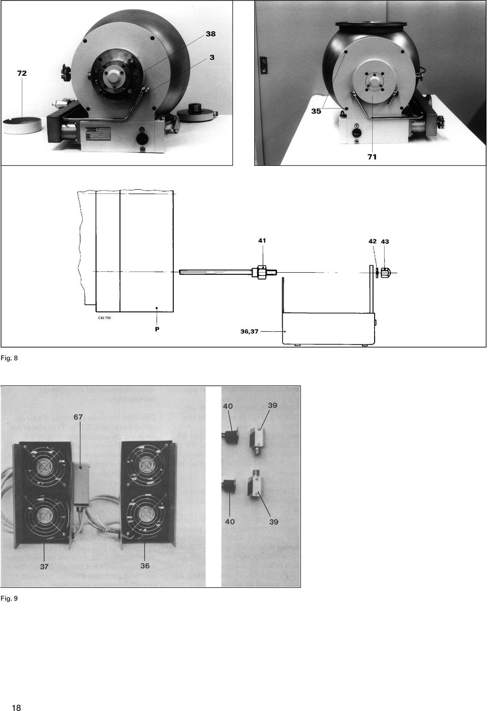
19 Fig. 10 Fig. 8, Fig. 9, Fig Kühlwasseranschluß 35 Schraube 36 Kühlgehäuse links 37 Kühlgehäuse rechts 38 Klemmenprint 39 Wärmekontaktschraube 40 Thermoschalter 41 Gewindestange 42 Federring 43 Hutmutter 44 Lüfter 45 Klemmleiste 46 Verbindungskabel 47 Kabel Einspeisung 67 Klemmenkasten 71 Lagerfassung 72 Haube P TPH 2200/TPU Cooling water connection 35 Screw 36 Cooling housing, left 37 Cooling housing, right 38 Terminal print 39 Heat contact screw 40 Thermal circuit breaker 41 Stud 42 Compression spring 43 Cap nut 44 Fan 45 Terminal board 46 Connecting cable 47 Cable feeder 67 Terminal box 71 Bearing mounting 72 Hood P TPH 2200/TPU Raccordement d eau de refroidissement 35 Vis 36 Boîtier de refroidissement gauche 37 Boîtier de refroidissement droite 38 PCB aux bornes 39 Vis de contact thermique 40 Interrupteur thermique 41 Tige filetée 42 Rondelle à ressort 43 Ecrou à chapeau 44 Ventilateur 45 Bornier 46 Câble de liaison 47 Câble d alimentation 67 Boîtier à borne 71 Corps de palier 72 Capot P TPH 2200/TPU 2200 Anschluß der Temperaturüberwachung Beide Kühlwasseranschlüsse 3 (Fig. 8) abschrauben und Wärmekontaktschrauben 39 einschrauben. Thermoschalter 40 an Wärmekontaktschrauben 39 anschrauben. Der Thermoschalter kann jeweils um 120 versetzt an den Schlüsselflächen montiert werden. Haube 72 (Fig. 8) abnehmen. Kabel des Thermoschalters 40 am Kühlwasserrohr 50 verlegen. Connecting the Temperature Monitoring Unscrew both cooling water connections 3 (Fig. 8) and screw in heat contact screws 39. Screw thermal Contact breaker 40 onto heat contact screws 39. The thermal contact breaker must be fitted to the sides of the heat contact screw head (each staggered 120 ). Remove hood 72 (Fig. 8). Place thermal Contact breaker 40 cable on cooling water pipe 50. Where water cooling is involved, terminals 6 and 7 on terminal print Raccordement du contrôleur de température Dévisser les deux raccordements d eau de refroidissement 3 (Fig. 8) et visser les vis de contact thermique 39. Visser l interrupteur thermique 40 aux vis de contact thermique 39. L interrupteur thermique peut être monté décalé de 120 sur les surfaces des clés. Enlever le capot 72 (Fig. 8). Déplacer l interrupteur thermique 40 sur la conduite d eau de refroidissement 50. Pour le refroidissement par eau, un pontage se trouve entre les bor- 19

20 Bei Wasserkühlung ist eine Brücke zwischen Klemme 6 und 7 an Klemmenprint 38. Diese Brücke muß bei Luftkühlung entfernt werden. Leitungen der Thermoschalter nach Schaltplan PM S anschließen. Beide Schalter 40 sind hintereinander geschaltet. Haube 72 aufsetzen und anschrauben. 38 should be bridged. For air cooling this bridge must be removed. Thermal Contact breaker leads should be connected as per Wiring Diagram PM S. Both switches 40 are switched in series. Screw on hood 72. nes 6 et 7 sur le PCB aux bornes 38. Ce pontage doit être enlevé pour un refroidissement par air. Raccorder les conducteurs de l interrupteur thermique suivant le schéma électrique PM S. Les deux interrupteurs 40 sont commutés en série. Replacer le capot 72 et le visser. Fig. 11 Schaltplan PM S mit Thermoschalter Antriebsmotor 23 Betriebsmittelpumpe 27 Klemmleiste 31 Motorhilfswicklung 33 Schalter 38 Klemmenprint 40 Thermoschalter (ohne Luftkühlung gebrückt) X8 Anschluß Antriebselektronik Wiring Diagram PM S with thermal circuit breaker Drive motor 23 Pump fluid pump 27 Terminal board 31 Motor auxiliary winding 33 Switch 38 Terminal print 40 Thermal circuit breaker (Bridged if no air cooling) X8 Connection, electronic drive unit Schéma électrique PM S avec interrupteur thermique Moteur d entraînement 23 Pompe de fluide moteur 27 Bornier 31 Bobinage auxiliaire moteur 33 Interrupteur 38 PCB aux bornes 40 Interrupteur thermique (Sans refroidissement par air ponté) X8 Raccord pour l électronique d entraînement 20

2 IP X4 WLS/FL IP24. Montage-Anleitung Instructions de montage Assembling instructions. 225 cm. 60 cm 0
 WLS/FL IP Arbeiten an den elektrischen Anlagen dürfen nur von autorisierten Fachleuten nach den örtlichen Vorschriften ausgeführt werden. Für nicht fachgerechte Installation wird jegliche Haftung abgelehnt.
11 EN 81-70 Page 1 of 2 Standard: INTERPRETATION RELATED TO. Clause(s): 5.4.2.3
: 5.4.2.3") CEN RELATED TO 11 Page 1 of 2 Standard: Edition: 2003 Clause(s): 5.4.2.3 Valid from: 15/09/2010 Date of modification: Key-word(s): Car operating panel, Two entrance lift Replacing interpretation No.: QUESTION
CEN RELATED TO 11 Page 1 of 2 Standard: Edition: 2003 Clause(s): 5.4.2.3 Valid from: 15/09/2010 Date of modification: Key-word(s): Car operating panel, Two entrance lift Replacing interpretation No.: QUESTION
CABLE TESTER. Manual DN-14003
 CABLE TESTER Manual DN-14003 Note: Please read and learn safety instructions before use or maintain the equipment This cable tester can t test any electrified product. 9V reduplicated battery is used in
Electrical tests on Bosch unit injectors
 Valid for Bosch unit injectors with order numbers 0 414 700 / 0 414 701 / 0 414 702 Parts Kit Magnet*: - F00H.N37.925 - F00H.N37.933 - F00H.N37.934 * For allocation to the 10-place Bosch order number,
IP X4 MOA/SL/FL IP44, CH IP24. Montage-Anleitung Instructions de montage Assembling instructions. 225 cm. 60 cm 0
 MOA/SL/FL IP44, CH IP4 Arbeiten an den elektrischen Anlagen dürfen nur von autorisierten Fachleuten nach den örtlichen Vorschriften ausgeführt werden. Für nicht fachgerechte Installation wird jegliche
Zubehör Accessories Accessoires
 Seite Page Page 14/2 DA 14/4 Allgemeine Merkmale Drehantrieb General parameters Rotary drive unit Caractéristiques générales Servomoteur rotatif + 16 Zubehör Accessories Accessoires 14/0 Drehantrieb Rotary
Power supply Interference suppressed acc. to DIN EN /- 4, EN 55011, EN CI. B, power factor corrected Power factor BöSha LED driver
 Operating Instructions LED Mast Double Luminaire Callisto SC DB, incl. Inclination Adjustment, Single-Chip Technology (Please, read carefully before starting operation) Version: 16.01.2017 Model 369-M
Electrical testing of Bosch common rail piezo injectors
 Applies to generation CRI 3: Bosch 10-position order number 0 445 115 = CRI 3-16 (CRI 3.0) 1600 bar 0 445 116 = CRI 3-18 (CRI 3.2) 1800 bar 0 445 117 = CRI 3-20 (CRI 3.3) 2000 bar Tools required: Hybrid
Honeywell AG Hardhofweg. D-74821 Mosbach MU1H-1220GE23 R1001
 BA 95 Einbau-Anleitung Installation Instructions Einbau Installation Einbaubeispiel Installation example Ablaufleitung vorsehen Install discharge pipework Durchflussrichtung beachten! Consider direction
Electrical testing of Bosch common rail Injectors
 Electrical testing of Bosch common rail Injectors Contents: 1. Adapter cable for Hybridtester FSA 050 (article number 0 684 010 050 / 1 687 023 571) 2. Electrical testing of Bosch common rail solenoid
RS232-Verbindung, RXU10 Herstellen einer RS232-Verbindung zwischen PC und Messgerät oder Modem und Messgerät
 Betriebsanleitung RS232-Verbindung, RXU10 Herstellen einer RS232-Verbindung zwischen PC und Messgerät oder Modem und Messgerät ä 2 Operating Instructions RS232 Connection, RXU10 Setting up an RS232 connection
Electrical testing of Bosch common rail solenoid valve (MV) injectors
 injectors") Applies to MV injector, generation: -CRI 1.0 / 2.0 / 2.1 / 2.2 -CRIN 1 / 2 / 3, with K oder AK plug Bosch 10-position order number Bosch-Bestellnummer CRI: 0 445 110 xxx Bosch-Bestellnummer CRIN: 0 445
Applies to MV injector, generation: -CRI 1.0 / 2.0 / 2.1 / 2.2 -CRIN 1 / 2 / 3, with K oder AK plug Bosch 10-position order number Bosch-Bestellnummer CRI: 0 445 110 xxx Bosch-Bestellnummer CRIN: 0 445
11 kw** E82MV222_4B kw**
 EDK82ZWKN4 00459189 10/02 Netzschleifklemme Typ E82ZWKN4 Diese Anleitung enthält wichtige Hinweise für den Einsatz der Netzschleifklemme E82ZWKN4 und beschreibt deren Montage. ist nur gültig - für Netzschleifklemmen
miditech 4merge 4-fach MIDI Merger mit :
 miditech 4merge 4-fach MIDI Merger mit : 4 x MIDI Input Port, 4 LEDs für MIDI In Signale 1 x MIDI Output Port MIDI USB Port, auch für USB Power Adapter Power LED und LOGO LEDs Hochwertiges Aluminium Gehäuse
Outdoor-Tasche. Operating Instructions Bedienungsanleitung GB D
 00 181243 Outdoor Case Outdoor-Tasche Splish Splash Operating Instructions Bedienungsanleitung GB D A B C D OPEN G Operating instruction 1. Important Notes Children are not permitted to play with the device.
08/12. Gebrauchsanleitung Trekkingrucksäcke Trekking rucksacks Instructions for use Notice d'emploi pour sacs à dos de trek
 08/12 Gebrauchsanleitung Trekkingrucksäcke Trekking rucksacks Instructions for use Notice d'emploi pour sacs à dos de trek X-TRANSITION Bedingungen der JACK WOLFSKIN 3-Jahres-Gewährleistung Terms and
Analogtechnik 2, Semestertest Technique analogique 2, Test de semestre
 Analogtechnik 2, Semestertest Technique analogique 2, Dr. Theo Kluter 05. 06. 2011 Name/Nom : Vorname/Prénom : Klasse/Classe : Aufgabe/ Punkte maximal/ Punkte erreicht/ Problème : Points maximaux : Points
Newest Generation of the BS2 Corrosion/Warning and Measurement System
 Newest Generation of the BS2 Corrosion/Warning and Measurement System BS2 System Description: BS2 CorroDec 2G is a cable and energyless system module range for detecting corrosion, humidity and prevailing
Kuhnke Technical Data. Contact Details
 Kuhnke Technical Data The following page(s) are extracted from multi-page Kuhnke product catalogues or CDROMs and any page number shown is relevant to the original document. The PDF sheets here may have
2 IP X4 TAI/LED IP44, CH IP24. Montage-Anleitung Instructions de montage Assembling instructions. 225 cm. 60 cm 0
 Montage-Anleitung Instructions de montage Assembling instructions TAI/LED IP, CH IP Sensor-Schalter aussen unten rechts Interrupteur sensitif en bas à l'extérieur à droite Sensor switch outside right below
Ex-Barriere für Diagnoseeinheit SITRANS DA400 / Ex-barrier for diagnostics unit SITRANS DA400 7MJ2010-1AA 0032
 Ex-Barriere für Diagnoseeinheit SITRANS DA400 / Ex-barrier for diagnostics unit SITRANS DA400 7MJ2010-1AA 0032 Warnung Elektrischer Anschluss in explosionsgefährdeten Bereichen Anschluss und Inbetriebnahme
https://portal.microsoftonline.com
 Sie haben nun Office über Office365 bezogen. Ihr Account wird in Kürze in dem Office365 Portal angelegt. Anschließend können Sie, wie unten beschrieben, die Software beziehen. Congratulations, you have
Serviceinformation Nr. 02/11
 Serviceinformation Nr. 02/11 vom: 06.10.2011 von: BAM 1. Software Navigator und Release Notes Auf unserer Homepage unter www.idm-energie.at/de/navigator-software.html steht ab sofort eine neue Version
Hazards and measures against hazards by implementation of safe pneumatic circuits
 Application of EN ISO 13849-1 in electro-pneumatic control systems Hazards and measures against hazards by implementation of safe pneumatic circuits These examples of switching circuits are offered free
Entwurf. preliminary
 KAPRi plus Erweiterungsset M12 KAPRi plus Extension Kit M12 KAPRi plus Kit d Extension M12 Bedienungsanleitung / User instructions / Instructions d installation 899366 KAPRi plus Erweiterungsset M12 /
CarMedia. Bedienungsanleitung Instruction manual. AC-Services Albert-Schweitzer-Str.4 68766 Hockenheim www.ac-services.eu info@ac-services.
 CarMedia Bedienungsanleitung Instruction manual AC-Services Albert-Schweitzer-Str.4 68766 Hockenheim www.ac-services.eu info@ac-services.eu DE Inhaltsverzeichnis 1. Allgemeine Hinweise... 3 2. CarMedia...
Cable Tester NS-468. Safety instructions
 Cable Tester NS-468 Safety instructions Do not use the cable tester NS-468 if it is damaged. This device is only for use inside dry and clean rooms. This device must be protected from moisture, splash
HF13-Programm HF13 Programme
 S. 221 HF13 plugs S. 222 HF13-Adapter HF13 adapters S. 223 HF13-Buchsen s 2 HF13 - Programm Die HF-Steckverbindungen der Serie 13/4 werden in Anlagen der Nachrichtentechnik (DIN 47 283 und DIN 47 284),
KURZANLEITUNG. Firmware-Upgrade: Wie geht das eigentlich?
 KURZANLEITUNG Firmware-Upgrade: Wie geht das eigentlich? Die Firmware ist eine Software, die auf der IP-Kamera installiert ist und alle Funktionen des Gerätes steuert. Nach dem Firmware-Update stehen Ihnen
PROFIBUS-DP Repeater 1 to 1 and 1 to 5 with optional level converter module
 LSS PROFIBUS-DP Repeater 1 to 1 and 1 to 5 with optional level converter module The LSS PROFIBUS-DP repeaters 1 to 1 and 1 to 5 are used for coupling up to six PROFIBUS bus segments in RS 485 bus technology.
Snap-in switch for switches PSE, MSM and MCS 30
 Product manual Snap-in switch for switches PSE, MSM and MCS 30 CONTENTS 1. PRODUCT DESCRIPTION 2. DATA AND DIMENSIONAL DRAWINGS 2.1. Technical Data 2.2. Dimensions of PSE with a Mounting Diameter 19 mm
ERHARD is a company of. Datasheet ERHARD ECR check valve
 ERHARD is a company of Datasheet The compact check valve for clamping The is clamped between two flanges as a reflux preventer. It has two vanes which, for example, open on starting a pump and will iediately
Aufgabe: Que faut-il faire? SK-Beispielaufgabe_Haustiere.docx
 Aufgabe: Que faut-il faire? SK-Beispielaufgabe_Haustiere.docx Lisez bien le sujet avant de vous précipiter sur votre copie et élaborez votre plan afin de préparer votre brouillon. On vous demande donc
ATEX-Check list. Compiled by: Date: Signature: Acceptable practice at the determination of flash point: Closed cup according to ISO 2719
 Fire and explosion hazard ATEX 137 1999/92/EG und ATEX 95 2014/34/EU Danger assessment and determination of explosion protection zone for the test space as well as the installation site ATEX-Check list
Description for the replacement of electronic controls for gas recovery
 Information on the replacement of the electronic control Description for the replacement of electronic controls for gas recovery Important information! The new electronic control for gas recovery with
Softwareupdate-Anleitung // AC Porty L Netzteileinschub
 1 Softwareupdate-Anleitung // AC Porty L Netzteileinschub Softwareupdate-Anleitung // AC Porty L Netzteileinschub HENSEL-VISIT GmbH & Co. KG Robert-Bunsen-Str. 3 D-97076 Würzburg-Lengfeld GERMANY Tel./Phone:
VIDEO CALL CAMERA G-VCAM-01
 VIDEO CALL CAMERA G-VCAM-01 EN AUS GUTEM GRUND ENGLISH 07-10 2 SAFETY AND INFORMATION Safety 7 This camera is designed to transmit video and audio signals. All other uses are expressly prohibited. 7 Protect
UWC 8801 / 8802 / 8803
 Wandbedieneinheit Wall Panel UWC 8801 / 8802 / 8803 Bedienungsanleitung User Manual BDA V130601DE UWC 8801 Wandbedieneinheit Anschluss Vor dem Anschluss ist der UMM 8800 unbedingt auszuschalten. Die Übertragung
Liebe Kolleginnen Liebe Kollegen
 Von: nebis-bibliotheken-request@nebis.ch im Auftrag von Gross Christine An: nebis-bibliotheken@nebis.ch Thema: NEBIS / Aleph V20: Neuerungen - Aleph V20: nouveautés Datum: Montag, 8. November 2010 15:57:57
Preisliste für The Unscrambler X
 Preisliste für The Unscrambler X english version Alle Preise verstehen sich netto zuzüglich gesetzlicher Mehrwertsteuer (19%). Irrtümer, Änderungen und Fehler sind vorbehalten. The Unscrambler wird mit
VDE Prüf- und Zertifizierungsinstitut Zeichengenehmigung
 Blatt / page 2 Dieses Blatt gilt nur in Verbindung mit Blatt 1 des sausweises Nr. This supplement is only valid in conjunction with page 1 of the. Warmwasserspeicher, geschlossen Storage water heater,
Technische Information
 Flüsskeitsgekühlte Anfahrkupplung Die Mähvorsätze der Typen 345 und 360 sind mit einer flüssigkeitsgekühlten Anfahrkupplung nachrüstbar. Best.-Nr.: LCA93830 (650Nm) für Best.-Nr: LCA93831 (900 Nm) für
USBASIC SAFETY IN NUMBERS
 USBASIC SAFETY IN NUMBERS #1.Current Normalisation Ropes Courses and Ropes Course Elements can conform to one or more of the following European Norms: -EN 362 Carabiner Norm -EN 795B Connector Norm -EN
User Manual Bedienungsanleitung. www.snom.com. snom Wireless Headset Adapter snom Schnurlos-Headset-Adapter. English. Deutsch
 English snom Wireless Headset Adapter snom Schnurlos-Headset-Adapter Deutsch User Manual Bedienungsanleitung 2007 snom technology AG All rights reserved. Version 1.00 www.snom.com English snom Wireless
Readme-USB DIGSI V 4.82
 DIGSI V 4.82 Sehr geehrter Kunde, der USB-Treiber für SIPROTEC-Geräte erlaubt Ihnen, mit den SIPROTEC Geräten 7SJ80/7SK80 über USB zu kommunizieren. Zur Installation oder Aktualisierung des USB-Treibers
Latvia Lettland Lettonie (02.12.2015)
") Latvia Lettland Lettonie (02.12.2015) (EN:) List of institutions and their registered experts carrying out conformity assessment of tankwagons used in the carriage of dangerous goods (DE:) Verzeichnis
Latvia Lettland Lettonie (02.12.2015) (EN:) List of institutions and their registered experts carrying out conformity assessment of tankwagons used in the carriage of dangerous goods (DE:) Verzeichnis
1 Allgemeine Information
 1 Allgemeine Information ACHTUNG! Der Betriebsdruck der Klasse 867 ist 6 bar. Sollte der Druck Ihrer Versorgungsleitung höher als 6 bar sein, muss der Druck an der Versorgungseinheit der Nähmaschine auf
Conditions de travail Arbeitsbedingungen
 Conditions de travail 39 Conditions de travail Emissions Conditions de travail Industriel: une profession 3 fois plus sûr! 9627 personnes sont assurées dans le domaine industriel en Valais. Le nombre d
juergen.vogt@uni-ulm.de
 Benutzerregistrierung für SciFinder on WWW Mitglieder, auch Studenten, der Universität Ulm können SciFinder Scholar für nicht-kommerzielle Zwecke nutzen. Allerdings ist der Zugang personalisiert. Damit
TECHNOLOGY MADE IN ITALY ÖLKÜHLER OIL COOLERS
 TECHNOLOGY MADE IN ITALY ÖLKÜHLER OIL COOLERS 113 ÖLKÜHLER - AIR/OIL COOLERS ALUMINIUM ALUMINUM Typ Models Öldurchfluss Oil flow capacity Lüfter Fan Kühlleistung Performance (40 C) Arbeits-- druck Pressure
Händler Preisliste Trade Price List 2015
 Händler Preisliste Trade Price List 2015 gültig ab / valid from 01.03.2015 Qualität die verbindet Driven by Quality Sehr geehrter Kunde, zu unserer neuen Preisliste möchten wir Ihnen nachfolgend einige
Downpipe Ford Focus ST MK3 Kit-Nr.:
 190001081 - Einbauanleitung / Installation Instruction - Downpipe Ford Focus ST MK3 Kit-Nr.: 500001025 Wichtige Hinweise! Diese Montageanleitung ist unbedingt vor Beginn der Einbauarbeiten zu lesen. Die
UP Unterputz-Montage Montage en encastré Recessed mounting
 Wandeinbau UP Unterputz-Montage Montage en encastré Recessed mounting PAL/LED IP4 Arbeiten an den elektrischen Anlagen dürfen nur von autorisierten Fachleuten nach den örtlichen Vorschriften ausgeführt
1 225 cm IP X4 SLI/FL IP24. Montage-Anleitung Instructions de montage Assembling instructions. 60 cm 0
 Sensor-Schalter aussen unten links und rechts SLI/FL IP Interrupteurs sensitifs en bas à l'extérieur à gauche et à droite Sensor switches outside left and right below Arbeiten an den elektrischen Anlagen
INSTALLATION AND OPERATING INSTRUCTIONS FOR LPS203-M LPS203-M 操 作 指 示
 BEDIENUNGSANLEITUNG To comply with the published safety standards, the following must be observed when using this power supply. Um den zur Zeit gültigen Sicherheitsbestimmungen zu genügen, müssen die nachstehenden
RZ 041. LISTED Control Nr.:95D1 Test Accessories. Isoprobe II 1:1. Benutzerinformation User Information Information pour l utilisateur
 RZ 041 LISTED Control Nr.:95D1 Test Accessories Isoprobe II 1:1 Benutzerinformation User Information Information pour l utilisateur Bemessungsspannung / Rated voltage / Tension assignée Isoprobe II - 1:1
Handbuch. Wir freuen uns, dass Sie sich für ein ultron Produkt entschieden haben und wünschen Ihnen viel Freude mit Ihrem neuen Gerät.
 Handbuch Wir freuen uns, dass Sie sich für ein ultron Produkt entschieden haben und wünschen Ihnen viel Freude mit Ihrem neuen Gerät. CE-Erklärung und Hinweise Hiermit erklärt die ultron AG, dass sich
Kurzanleitung um Transponder mit einem scemtec TT Reader und der Software UniDemo zu lesen
 Kurzanleitung um Transponder mit einem scemtec TT Reader und der Software UniDemo zu lesen QuickStart Guide to read a transponder with a scemtec TT reader and software UniDemo Voraussetzung: - PC mit der
S-Digicash Payez mobile depuis votre compte courant! Mobil bezahlen, direkt von Ihrem Girokonto aus! Pay mobile from your current account!
 S-Digicash Payez mobile depuis votre compte courant! Mobil bezahlen, direkt von Ihrem Girokonto aus! Pay mobile from your current account! Payez mobile depuis votre compte courant BCEE! Scannez le QR Code
Aufbaudose mit Schalter Spacing box with switch. Montageanleitung mounting instructions
 Aufbaudose mit Schalter Spacing box with switch Montageanleitung mounting instructions body head Aufbaudose mit Schalter Montageanleitung S. 2 mounting instructions p. 9 $ 0.2m Sicherheitshinweise Die
Bayerisches Landesamt für Gesundheit und Lebensmittelsicherheit Pool water quality the German philosophy
 Bayerisches Landesamt für Gesundheit und Lebensmittelsicherheit Pool water quality the German philosophy Christiane Höller Bavarian Health and Food Safety Authority Legal regulations 1979 Federal Law on
Zusatz-Betriebsanleitung nach ATEX
 1. Allgemeines nach ATEX Diese enthält grundlegende Hinweise für den Einsatz in explosionsgefährdeten Bereichen, die bei Montage, Betrieb und Wartung zu beachten sind. Daher ist diese unbedingt vor Montage
Parameter-Updatesoftware PF-12 Plus
 Parameter-Updatesoftware PF-12 Plus Mai / May 2015 Inhalt 1. Durchführung des Parameter-Updates... 2 2. Kontakt... 6 Content 1. Performance of the parameter-update... 4 2. Contact... 6 1. Durchführung
elektr. Stellungsgeber electr. position transmitter electr. convertisseur de position REtrans2W REtrans4W REtrans2W REtrans-8010 Inhaltsverzeichnis
 Installation and operating instructions elektr. Stellungsgeber electr. position transmitter electr. convertisseur de position REtrans8010 Baureihe / Series / Séries /4W Inhaltsverzeichnis Contents Sommaire
p^db=`oj===pìééçêíáåñçêã~íáçå=
 p^db=`oj===pìééçêíáåñçêã~íáçå= Error: "Could not connect to the SQL Server Instance" or "Failed to open a connection to the database." When you attempt to launch ACT! by Sage or ACT by Sage Premium for
Rohrschieber mit Schließfeder Slide Valve spring loaded
 Rohrschieber mit Schließfeder Slide Valve spring loaded Rohrschieber als automatisches Entlüftungsventil Slide Valve as automatic air relief valve Type: RSF DN: 50 300 (2 12 ) PN: 16 160 (Class 150 900)
SWC SPANNLAGER UND GEHÄUSE SWC RADIAL INSERT BALL BEARINGS AND HOUSING
 SWC SPANNLAGER UND GEHÄUSE SWC RADIAL INSERT BALL BEARINGS AND HOUSING SWC bietet Gehäuseeinheiten bestehend aus einem Spannlager und wahlweise Stehgehäuse (UCP), Zweiloch-Flansch-Gehäuse (UCFL) oder Vierloch-Flansch-Gehäuse
EN Instructions for use / assembly instructions 2 DE Gebrauchsanleitung / Montageanleitung 4. Exafill
 EN Instructions for use / assembly instructions 2 DE Gebrauchsanleitung / Montageanleitung 4 Exafill 58129003 English Safety Notes Gloves should be worn during installation to prevent crushing and cutting
OPERATING INSTRUCTIONS Test pump ZG 5.1. and ZG 5.2.
 Elektromotoren und Gerätebau Barleben GmbH OPERATING INSTRUCTIONS Test pump ZG 5.1. and ZG 5.2. Elektromotoren und Gerätebau Barleben GmbH 2 Inhaltsverzeichnis Page 1 Use 4 2 Design features 4 2.1 Test
GB/DE/AT. Fitting instructions/montageanleitung
 GB/DE/AT Fitting instructions/montageanleitung devicrimp CS-2A Fitting set for twin conductor cables Art. no. 18055350 Reparatur und Verbindungsset für Dünnbettheizmatten mit einem Anschluß Best.-Nr. 18-055422
FIRMWARE UPDATE TAPMOTION TD
 FIRMWARE UPDATE TAPMOTION TD CMP-SPF TO WHOM IT MAY CONCERN Seite 1 von 9 Inhalt / Overview 1. Firmware überprüfen und Update-file auswählen / Firmware check and selection of update file 2. Update File
DE Montageanleitung RG120 Fertigmontage-Set mit Griffeinheit für Absperr-Wasserzähler-Montageblock
 Montageanleitung RG120 Fertigmontage-Set mit Griffeinheit für Absperr-Wasserzähler-Montageblock Installation Manual RG120 External parts with handles for shut-off water meter assembly block Fig. 96 11
OPERATING INSTRUCTIONS
 OPERATING INSTRUCTIONS for Gas Cartridge Adapter CP250 Part no. 144051 and Gas Cartridge Adapter CV300/470 Part no. 144052 CP 250 CV 300/470 144959_V04 Safety Precautions Possible dangers if the safety
Fitting Instructions for DG0017 BK Downpipe Grille BMW F800GT 2013
 Fitting Instructions for DG0017 BK Downpipe Grille BMW F800GT 2013 In This Kit There Should Be 1 x Downpipe Grille (DG0017) 2 x M5 Nyloc nuts PICTURE 1 PICTURE 2 PICTURE 3 PICTURE 4 1 PICTURE 5 PICTURE
Therefore the respective option of the password-protected menu ("UPDATE TUBE DATA BASE") has to be selected:
 has to be selected:") ENGLISH Version Update Dräger X-act 5000 ("UPDATE TUBE DATA BASE") The "BARCODE OPERATION AIR" mode is used to automatically transfer the needed measurement parameters to the instrument. The Dräger X-act
ENGLISH Version Update Dräger X-act 5000 ("UPDATE TUBE DATA BASE") The "BARCODE OPERATION AIR" mode is used to automatically transfer the needed measurement parameters to the instrument. The Dräger X-act
 Verwenden Sie nur Original-KRONE-Ersatzteile! Das gibt Sicherheit und spart Kosten! Use Original-KRONE parts only This will increase operational reliability and help to save costs! N'utiliser que des piéces
Legierungsgruppe I / Groupe d'alliages I : Legierungsgruppe II / Groupe d'alliages II :
 Die verschiedenen Ausführungen von Bleche Les diverses exécutions de tôles NQ Normalqualität (= NQ) ist Material geeignet für normale Ansprüche, die Bleche sind lackierfähig. Eloxieren ist nur mit Einschränkungen
 Verwenden Sie nur Original-KRONE-Ersatzteile! Das gibt Sicherheit und spart Kosten! Use Original-KRONE parts only This will increase operational reliability and help to save costs! N'utiliser que des piéces
 Verwenden Sie nur Original-KRONE-Ersatzteile! Das gibt Sicherheit und spart Kosten! Use Original-KRONE parts only This will increase operational reliability and help to save costs! N'utiliser que des piéces
U 4814 U 4818 U 4851 U 4852 U 4854 U 4855 U 4856
 Umwälzpumpen Circulating pump Ersatzteil-Liste Spare parts list U 4814 U 4818 U 4851 U 4852 U 4854 U 4855 U 4856 Stand: 20.05.11 Ident Nr. 27 104 17B U 4814 Seite / Page 4 U 4818 Seite / Page 6 U 4851
Flow through sight glasses Nr. 440/450
 Flow through sight glasses Nr. 4/450 Durchfluss-Schaugläser in Eckform (Nr. 4) und Dreiwegeform (Nr. 450) mit Flanschanschluss bis Gehäuse in Schweißkonstruktion mit Einlaufstutzen, beiderseits Schauglasplatten
Release Notes BRICKware 7.5.4. Copyright 23. March 2010 Funkwerk Enterprise Communications GmbH Version 1.0
 Release Notes BRICKware 7.5.4 Copyright 23. March 2010 Funkwerk Enterprise Communications GmbH Version 1.0 Purpose This document describes new features, changes, and solved problems of BRICKware 7.5.4.
-BOO- - F - 24 V DC 100 % ED
 e s Bestellformel 4 -BOO- - F - 24 V DC ED Order specifications Drehmagnet Rotary solenoid Größe (,, 9) Size (,, 9) Drehwinkel 2 4 2 4 Angular travel 2 4 6 9 Ausführung beidseitiges Wellenende Anschlussart
Firma, Adresse: Company, Adress. Namen der verantwortlichen für die Qualitätssicherung: Names of resposible person for quality assurance:
 Firma, Adresse: Company, Adress Namen der verantwortlichen für die Qualitätssicherung: Names of resposible person for quality assurance: 1. Qualitätsnachweis Quality control Werden Prüfunterlagen systematisch
Instructions de montage. Spiegel / Leuchten / SP.1 SP.2 LE.2 LE.3 LE.1 LE.7 LE.4 LE /
 Montageanleitung Montageaanwijzing Monteringsanvisining Instrucciones de montaje Assembly Instruction Instructions de montage Instruzioni di montaggio Spiegel / Leuchten / Mirror Lamps SP.1 SP.2 A LE.1
Electromagnetic Flowmeter FXE4000-DE43F
 Pos: 2 /Grid-Layout/Titelblätter/Ersatzteilblätter/Durchfluss/FXE4000-DE43F @ 65\mod_1350460748604_3101.docx @ 523546 @ @ 1 === Ende der Liste für Textmarke Cover === Spare Parts List SPL/FXE4000-DE43F-EN
/ Technische Änderungen und drucktechnische Irrtümer vorbehalten.
 EZ-0225-V10 Air Bearing Spindle High accurancy air bearing spindle with direct drive. Equipped with an water-cooled synchronous motor (frequency at nominal speed 400 Hz), Power output 1880 W. Rotary encoder
Building Instructions. Aufbauanleitung. Service-Hotline:
 86488-2006 02.02.2012 Aufbauanleitung Building Instructions Service-Hotline:+49 421 38693 33 86488-2006 Vergleichen Sie zuerst die Materialliste mit Ihrem Paketinhalt! Bitte haben Sie Verständnis, daß
MobiDM-App Handbuch für Windows Mobile
 MobiDM-App Handbuch für Windows Mobile Dieses Handbuch beschreibt die Installation und Nutzung der MobiDM-App für Windows Mobile Version: x.x MobiDM-App Handbuch für Windows Mobile Seite 1 Inhalt 1. WILLKOMMEN
TPH 062 / TPU 062 TPH 055
 Betriebsanleitung Operating Instructions Instructions de service TPH 062 / TPU 062 TPH 055 Turbomolekularpumpen Turbomolecular Pumps Pompe turbomoléculaire TPH 062 TPU 062 TPH 055 PM 800 260 BN/E (9702)
Specification. DESIGN Swing check valves for return fl ow prevention in piping systems to be mounted directly between fl anges acc. to DIN.
 Technische Daten BAUFORM Rückschlagklappen zur Rückfl ussverhinderung in Rohrleitungssystemen für den Einbau zwischen DIN Flanschen. ANSCHLUß Flansch DN32 DN500 bemessen für Flansch nach PN16 BETRIEBSDRUCK
ETD 34/17/11. Magnetic characteristics (per set) Σl/A = 0,81 mm 1 l e = 78,6 mm A e = 97,1 mm 2 A min = 91,6 mm 2 V e = mm 3
 Σl/A = 0,81 mm 1 l e = 78,6 mm A e = 97,1 mm 2 A min = 91,6 mm 2 V e = mm 3") Core B66361 In accordance with IEC 61185 Quality assurance per UTE 83313-001/ CECC 25 301-001 (material N27) For SMPS transformers with optimum weight/performance ratio at small volume ETD cores are supplied
Core B66361 In accordance with IEC 61185 Quality assurance per UTE 83313-001/ CECC 25 301-001 (material N27) For SMPS transformers with optimum weight/performance ratio at small volume ETD cores are supplied
Evidence of Performance
 Air permeability, Watertightness, Resistance to wind load, Operating forces, Mechanical properties, Mechanical durability, Impact resistance Expert Statement No. 15-002226-PR01 (02) Product Designation
AP Aufputz-Montage Montage en applique Surface mounting
 PAL/LED IP44, CH IP4 AP Aufputz-Montage Montage en applique Surface mounting Arbeiten an den elektrischen Anlagen dürfen nur von autorisierten Fachleuten nach den örtlichen Vorschriften ausgeführt werden.
USB Signalverstärker XL
 USB Signalverstärker XL Bedienungsanleitung Identifizierung Hersteller:... TLS Communication GmbH Marie-Curie-Straße 20 D-40721 Hilden Tel: +49 (0) 2103 5006-0 Fax: +49 (0) 02103 5006-90 Produkt:... USB
DE Gebrauchsanleitung / Montageanleitung 2 EN Instructions for use / assembly instructions 3 E / S / Metris S /
 DE Gebrauchsanleitung / Montageanleitung 2 EN Instructions for use / assembly instructions 3 13423000 / 13424000 31416000 / 31417000 Deutsch Sicherheitshinweise Bei der Montage müssen zur Vermeidung von
Handbuch. Artologik EZ-Equip. Plug-in für EZbooking version 3.2. Artisan Global Software
 Artologik EZ-Equip Plug-in für EZbooking version 3.2 Artologik EZbooking und EZ-Equip EZbooking, Ihre webbasierte Software zum Reservieren von Räumen und Objekten, kann nun durch die Ergänzung um ein oder
PNEUMATISCHE PUMPEN PNEUMATIC PUMPS
 BVBA POMAC-LUB-SERVICES SPRL Korte Bruggestraat 28 B-8970 Poperinge Tel. 057/33 48 36 Fax 057/33 61 27 info@pomac.be internet: www.pomac.be EINLEITUNGSSCHMIERSYSTEM MIT VOLUMETRISCHEN DOSIERVENTILEN FÜR
PRO SCAN WASSERANALYSE PER SMARTPHONE WATER ANALYSIS BY SMARTPHONE ANALYSE DE L EAU PAR SMARTPHONE
 N02 WASSERANALYSE PER SMARTPHONE WATER ANALYSIS BY SMARTPHONE ANALYSE DE L EAU PAR SMARTPHONE NO 2 NO 3 ph Cl 2 CO 2 ANALYSE DIAGNOSE LÖSUNG ANALYSIS DIAGNOSIS SOLUTION THE NEW GENERATION ph KH GH N03
CONTROLLER RECEIVER REPEATER PAIRING SLIM CLIP
 ANLEITUNGEN // INSTRUCTIONS CONTROLLER RECEIVER REPEATER PAIRING SLIM CLIP BEDIENUNGSANLEITUNG // INSTRUCTION MANUAL MONTAGEANLEITUNG // ASSEMBLY INSTRUCTION MONTAGEANLEITUNG // ASSEMBLY INSTRUCTION KOPPLUNG