Kit Number Ford Fiesta MK6 1.2i, 1.4i, 1.6i 2008-on
|
|
|
- Kirsten Gerstle
- vor 6 Jahren
- Abrufe
Transkript
 3. Remove the breather hose from the cam cover. (Fig. 3) 4. Unclip & remove the air box feed located on the slam panel as shown. (Fig. 4) 5.")
 7. Carefully expand the flexi cold air hose.")
 9. Assemble the saddle bracket / mounting bracket using the allen head bolt, nylon conical washer, flat metal washer & nylock nut. (Fig. 9) 10.")
 11.")
 14.")

 18.")
. Parts list: 1 x Filter Element.")
1 Kit Number Ford Fiesta MK6 1.2i, 1.4i, 1.6i 2008-on Instruction sheet A Disconnect the negative terminal from the vehicle battery. 2. Unclip & remove the intake hose from the air box lid. (Fig. 1&2) 3. Remove the breather hose from the cam cover. (Fig. 3) 4. Unclip & remove the air box feed located on the slam panel as shown. (Fig. 4) 5. If fitted unclip & remove the electrical harness plug from the MAS (Mass Air Sensor). (Fig. 5) 6. Carefully pull the air box assembly out of its mountings & remove the air box assembly from the vehicle. (Fig. 6) 7. Carefully expand the flexi cold air hose. Feed the hose down to the lower bumper & secure the hose to the bumper spoiler trim using the plastic ties supplied. (Fig. 7) 8. Secure the top of the hose as shown using the plastic tie supplied. (Fig. 8) 9. Assemble the saddle bracket / mounting bracket using the allen head bolt, nylon conical washer, flat metal washer & nylock nut. (Fig. 9) 10. Remove the rubber grommet from the left air box mounting point. Mount the bracket assembly to the air box mounting point using the bolt, small flat washer, large flat washers & nylock nut supplied as shown. (Fig.10) 11. MAS models only: Unscrew & remove the MAS from the air box lid as shown. (Fig.11) 12. MAS models only: Carefully remove the blank from the new MAS tube as shown. (Fig.12) 13. MAS models only: Fit the MAS to the new intake tube using the screws supplied. (Fig.13) 14. Fit the new intake tube to the original intake hose (ensuring that the direction of flow on the tube is directed towards the intake hose) & secure using the original hose clamp. (Fig.14) 15. Fit the filter onto the intake tube; ensure that the neck of the filter sits onto the saddle bracket. Place the hose clamp around both the saddle bracket & tighten the hose clamp as shown. (Fig.15) 16. MAS models only: Reconnect the electrical harness plug to the MAS. (Fig.16) 17. Fit the barbed adaptor into the end of the new breather hose supplied. Join the other end of the hose to the engine breather located on the cam cover. (Fig.17) 18. Route the new breather hose to the filter & insert the breather hose adaptor into the hole in the base of the filter as shown. (Fig.18) 19. Reconnect the negative battery terminal. 20. Carry out a final check of the height / alignment of the K&N induction system before starting the engine. Installation is now complete. (Fig.19). Parts list: 1 x Filter Element. 1 x Flexi Cold Air Hose. 1 x Rubber Breather Hose. 1 x Plastic Intake Tube. 1 x Literature Pack. Fixing Kit :- 3 x Plastic Tie. 1 x Mounting Bracket. 1 x Saddle Bracket. 1 x M6 C sunk Bolt. 1 x M6x20mm Hex Bolt. 2 x M6 Nylock Nut. 2 x M6 Small Flat Washer. 1 x Nylon Conical Washer. 2 x M6 Large Flat Washer. 1 x 65/89mm Hose Clamp. 1 x ½ x½ Vent Adaptor. 2 x M4 Plas Fix Screw. WARNING: Before starting the engine carry out a final fitment check of the K&N performance kit. It will be necessary for all intake systems to be checked periodically for realignment, clearance and tightening of all connections. Failure to follow the above instructions or proper maintenance may void the warranty. FILTER MAINTENANCE: K&N suggests checking the filter periodically for excessive dirt build-up. When the element becomes covered in dirt (or once a year), service it according to the instructions on the Recharger service kit available from your K&N dealer, part number EU. Fig. # 1 Fig. # 2 Fig. # 3 Fig. # 4 Fig. # 5 Fig. # 6 Fig. # 7 Fig. # 8


2 Fig. # 9 Fig. # 10 Fig. # 11 Fig. # 12 Fig. # 13 Fig. # 14 Fig. # 15 Fig. # 16 Fig. # 17 Fig. # 18 Fig. # 19
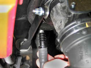
3 Artikelnummer Instructieblad No. A Haal de sleutel uit het contactslot en neem de negatieve accukabel Onderdelen 2. (Fig. 1) Maak de slangklem los en verwijder de inlaatslang van het luchtfilterhuis zoals afgebeeld. 3. (Fig. 3) Verwijder de ontluchtingsslang van de motor zoals afgebeeld. Filter-Element 4. (Fig. 4) Verwijder de inlaatslang naar het luchtfilterhuis van de inlaatsnorkel Flexibele Koude-Luchtslang zoals afgebeeld. Ontluchtingsslang 5. (Fig. 5) Neem de stekker van de luchtmassameter (LMM) los. 6. (Fig. 6) Kunststof Inlaatpijp Trek voorzichtig de het complete luchtfilterhuis uit zijn bevestigingsrubbers en verwijder het uit de auto zoals afgebeeld. Documentatieset 7. (Fig. 7) Trek de flexibele koude-luchtslang voorzichtig uit. Inbouwkit:- 8. (Fig. 7) Maak het het einde van de flexibele koude-luchtslang vast aan de bodemplaat/bumperspoiler met de geleverde tie-wraps; zorg dat de 3x Tie-Wrap slang naar voren wijst. Beugel 9. (Fig. 8) Maak het het einde van de flexibele koude-luchtslang vast met een Halfronde Beugel geleverde tie-wrap zoals afgebeeld. 10. (Fig. 9) Monteer de halfronde beugel op de bevestigingsbeugel met de Bout, Inbus M6 bijgeleverde platkopschroef, conische ring, platte metalen ring en Bout M6x20 borgmoer. Borgmoer M6 11. (Fig. 10) Verwijder het ophangrubber uit het aangeduide montagepunt van het luchtfilterhuis. Metalen Ring M6 12. (Fig. 10) Monteer de samengestelde beugel aan het ophangpunt van het Conische Ring, Nylon luchtfilterhuis met de originele rubberen ring en de geleverde bout, Metalen Ring M6, groot vlakke ring, 2 grote vlakke ringen en borgmoer zoals afgebeeld; plaats de ringen aan weerszijden van de rubberen ring. Slangklem Alleen modellen met LMM Slang-Adapter, Recht 13. (Fig. 11) Draai de schroeven los en verwijder voorzichtig de LMM van het luchtfilterhuis. 14. (Fig. 12) Verwijder voorzichtig de plug van de nieuwe LMM buis zoals afgebeeld 15. (Fig. 13) Monteer de LMM voorzichtig in het gat in de kunststof inlaatbuis met de geleverde schroeven. 16. (Fig. 14) Bevestig de samengestelde inlaatbuis aan de originele inlaatbuis met de geleverde slangklem zoals afgebeeld. Nog niet geheel vastzetten! 17. (Fig. 15) Plaats de geleverde slangklem om de halfronde beugel en de inlaatslang. 18. (Fig. 15) Plaats het samengestelde filter door de halfronde beugel, in de inlaatslang, en maak het vast met de geleverde slangklem zoals afgebeeld. Alleen modellen met LMM 19. (Fig. 16) Sluit de stekker weer aan op de LMM. 20. (Fig. 17) Steek de geleverde slang-adapter in de ontluchtingsslang zoals afgebeeld. 21. (Fig. 17) Schuif de geleverde ontluchtingsslang om de aansluiting op de motor 22. (Fig. 18) Steek de slang-adapter in het gat in de onderkant van het filter. Zelftappende Schroef 23. Sluit de negatieve accukabel weer aan. 24. (Fig. 19) Controleer nogmaals of alle onderdelen goed bevestigd zijn en vrij liggen alvorens de motor te starten. De inbouw is nu voltooid.
4 Artikelnummer Instruktionsblatt No. A Nehme den Schlüssel aus dem Kontaktschloß und klemme das Teile Minuskabel der Batterie ab. 2. (Fig. 1) Löse und entferne den Lufteinlaßschlauch vom Luftfiltergehäuse wie abgebildet. 3. (Fig. 3) Entferne den Entlüftungsschlauch vom Motor wie abgebildet. 4. (Fig. 4) Entferne das Einsaugrohr zum Luftfiltergehäuse vom Einlaßsnorkel wie abgebildet. 5. (Fig. 5) Löse und entferne den Stecker vom Luftmengenmesser (LMM). 6. (Fig. 6) Ziehe vorsichtig das komplette Luftfiltergehäuse aus seinen Gummistützen und entferne es vom Fahrzeug wie abgebildet. 3x 7. (Fig. 7) Dehne vorsichtig den gelieferten flexibelen Kaltluftschlauch aus. 8. (Fig. 7) Befestige den flexibelen Kaltluftschlauch an die Bodenwanne/Frontspoiler mit den gelieferten Kabelbindern, achte darauf daß der Schlauch nach vorne steckt. 9. (Fig. 8) Befestige den flexibelen Kaltluftschlauch mit einem gelieferten Kabelbinder wie abgebildet. 10. (Fig. 9) Befestige den halbrunden Bügel zusammen mit der Halterung mit der gelieferten Senkschraube, konischem Zwischenring, flachem Metallring & Verschlußmutter. 11. (Fig. 10) Entferne die Gummistütze vom angezeigten Montagepunkt des Luftfiltergehäuses. 12. (Fig. 10) Befestige die zusammengestellte Halterung auf den Montagepunkt des Luftfiltergehäuses mit dem Originalgummiring und gelieferten Bolzen, flachem Metallring, großen flachen Metallringen und Verschlußmutter wie abgebildet. Platze die 2 großen Ringen um die Gummiring. Nur Modelle mit LMM 13. (Fig. 11) Löse die Schrauben und entferne vorsichtig den LMM vom Luftfiltergehäuse. 14. (Fig. 12) Entferne vorsichtig die Verschlußkappe vom neuen LMMschlauch wie abgebildet. 15. (Fig. 13) Montiere den LMM vorsichtig ins Loch im Kunststoffeinlaßrohr mit den gelieferten Schrauben. 16. (Fig. 14) Befestige das zusammengestellte Einlaßrohr aufs Originaleinlaßrohr mit der gelieferten Schlauchschelle wie 17. (Fig. 15) Schiebe die gelieferte Schlauchschelle um den halbrunden Bügel Einlaßschlauch. 18. (Fig. 15) Platze den zusammengestellten Filter durch den halbrunden Bügel, in den Einlaßschlauch, und befestige ihn mit der gelieferten Nur Modelle mit LMM 19. (Fig. 16) Schließe den Stecker wieder an auf den LMM. 20. (Fig. 17) Schiebe den gelieferten Entlüftungsadaptor in den 21. (Fig. 17) Schiebe den gelieferten Belüftungsschlauch um den Anschluß auf dem Motor wie abgebildet. 22. (Fig. 18) Schiebe den Entlüftungsadaptor ins Loch im Filterboden. 23. Schließe das Minuskabel der Batterie wieder an. 24. (Fig. 19) Prüfe nochmals, bevor Sie den Motor starten, ob alle Teile ausreichend Zwischenraum haben und richtig fest sind. Die Installation ist nun beendet. Luftfilter Flexibelen Kaltluftschlauch Entlüftungsschlauch Einlaßrohr, kunststoff Dokumentationssatz Einbaukit:- Kabelbinder Halterung Halbrunden Bügel Bolzen, Innensechskant M6 Bolzen, M6x20 Verschlußmutter, M6 Kunststoffring, konisch, Nylon Metallring, M6 Metallring, M6- groß Schlauchschelle Entlüftungsadaptor, recht Schneidschraube
5 Kit référence Feuille d'instructions No. A Prener le clef du contact et déconnecter le terminal négatif de la Liste des pièces batterie. 2. (Fig. 1) Décliper le collier de serrage et prener le tuyau d'admission de la boîte à air comme indiqué. Élément Filtercharger 3. (Fig. 3) Enlever la canalisation de reniflard du moteur comme indiqué. Canalisation flexible d'air froid 4. (Fig. 4) Enlever le tube d'admission vers la boîte à air de l'écope d'admission 5. (Fig. 5) Déconnecter la connexion électrique du débitmètre (DBM). Canalisation reniflard 6. (Fig. 6) Tirer avec précaution la complète boîte à air de ses supports en Tube d'admission, plastique caoutchouc et l'enlever de la voiture comme indiqué. Pack documentation 7. (Fig. 7) Étirer avec précaution la canalisation flexible d air froid. 8. (Fig. 7) Fixer la canalisation flexible d air froid vers le bas jusqu au spoiler inférieur en utilisant des colliers plastiques fournis; assurer que la 3x Kit de Montage:- Collier plastique canalisation est orientée vers l'avant de la voiture. 9. (Fig. 8) Fixer la canalisation flexible d air froid en utilisant un collier plastique Support fourni comme indiqué. Support, demi-rond 10. (Fig. 9) Installer le support demi-rond sur le support en utilisant la vis à tête fraisée, la rondelle conique, la rondelle plate et l écrou Nylock fournis. Boulon, tête bombée, M6 11. (Fig. 10) Enlever le support en caoutchouc du montage indiqué de boîte à air. Boulon, M6x (Fig. 10) Installer le support assemblé sur la montage de boîte à air en utilisant Écrou, Nylock, M6 la rondelle en caoutchouc originale, et le boulon, écrou Nylock, rondelle plâte et 2 rondelles plâtes grandes fournis comme indiqué. Rondelle, métal, M6 Placer les 2 rondelles autour du rondelle en caoutchouc. Rondelle conique, Nylon Seulement les modèles avec DBM 13. (Fig. 11) Rondelle, métal, M6, grande Dévisser les vis et enlever avec précaution le DBM de la boîte à air. Collier de serrage (Fig. 12) Enlevez soigneusement le prise du tayau du DBM comme montré Adapteur reniflard, droit 15. (Fig. 13) Monter avec précaution le DBM dans le trou dans le tube d'admission en plastice en utilisant les vis fournis. 16. (Fig. 14) Installer le tube d'admission assemblé sur le tube d'admission original en utilisant le collier de serrage fourni comme indiqué. Ne pas serrer entièrement maintenant! 17. (Fig. 15) Installer le collier de serrage fourni autour du support demi-rond canalisation d'admission. 18. (Fig. 15) Installer le filtre assemblé par le support demi-rond, dans la canalisation d'admission, en utilisant le collier de serrage fourni comme indiqué. Seulement les modèles avec DBM 19. (Fig. 16) Reconnecter la connexion électrique du DBM. 20. (Fig. 17) Insérer l'adapteur reniflard fourni dans la canalisation de reniflard comme indiqué. 21. (Fig. 17) Installer la canalisation de reniflard fournie sur le tube de reniflard du moteur comme indiqué. 22. (Fig. 18) Insérer l'adapteur reniflard dans le trou dans le fond du filtre. Vis, auto-fixante 23. Reconnecter le terminal négatif de la batterie. 24. (Fig. 19) Effectuer un contrôle final de l alignement et de la hauteur du kit. L installation est maintenant achevée.
Fig. # 1 Fig. # 2 Fig. # 3 Fig. # 4. Fig. # 5 Fig. # 6 Fig. # 7 Fig. # 8
 Kit Number 57-0632 Ford Focus II, 1.4L 2004-2007 & Ford Focus 1.6L II, 16v 100bhp, 2004-2007 Instruction sheet 1. Disconnect the negative terminal from the vehicle battery. 2. Unclip & remove the intake
Kit Number Ford Focus, 1.8L / 2.0L L4 - Instruction sheet A
 Kit Number 57-0304-1 Ford Focus, 1.8L / 2.0L L4 - Instruction sheet A2054-684 1. Disconnect the negative terminal from the vehicle battery. 2. Disconnect & remove the harness plug from the MAS (Mass Air
Note: This kit fits both models with and without Mass Air Sensor (MAS). Vehicles without MAS have a plain tube fitted instead of the MAS.
. Vehicles without MAS have a plain tube fitted instead of the MAS.") Kit Number 57-0303-1 Ford Focus I, 1.4L&1.6L L4 16v, 74&99 bhp, 1998-2005 Instruction sheet A2054-718 Note: This kit fits both models with and without Mass Air Sensor (MAS). Vehicles without MAS have a
Kit Number 57-0303-1 Ford Focus I, 1.4L&1.6L L4 16v, 74&99 bhp, 1998-2005 Instruction sheet A2054-718 Note: This kit fits both models with and without Mass Air Sensor (MAS). Vehicles without MAS have a
Part Number Instruction Sheet No.A Page 1 of 2
 Instruction Sheet No.A2054-562 Page 1 of 2 Part Number 57-0526 INSTALLATION INSTRUCTIONS 1. Disconnect the negative terminal from the battery. 2. Unclip & remove the electrical harness plug from the MAS
Kit Number Nissan Note 1.5L 16v Dci L on Instruction sheet A
 Kit Number 57-0676 Instruction sheet A2054-787 1. Take the keys from the ignition and disconnect the negative battery terminal. 2. Unclip the airbox intake hose from the slam panel and remove from the
Ford Fiesta V 1.4L TDCI L4 OHC 02-07
 Instruction Sheet No.A2054-595 Page 1 of 2 Part Number 57-0557 INSTALLATION INSTRUCTIONS 1. Disconnect the negative terminal from the battery. 2. Unscrew and remove the airbox lid. (Fig. 1) 3. Unscrew
Kit Number 57A K&N Apollo Closed Intake System (CIS) Vauxhall/Opel Astra H 1.6L, 1.8L, 2L Turbo April 05.. Instruction sheet A
 Vauxhall/Opel Astra H 1.6L, 1.8L, 2L Turbo April 05.. Instruction sheet A") Kit Number 57A-6016 K&N Apollo Closed Intake System (CIS) Vauxhall/Opel Astra H 1.6L, 1.8L, 2L Turbo April 05.. Instruction sheet A2054-675 APOLLO 1. Disconnect the negative terminal from the vehicle battery.
Kit Number 57A-6016 K&N Apollo Closed Intake System (CIS) Vauxhall/Opel Astra H 1.6L, 1.8L, 2L Turbo April 05.. Instruction sheet A2054-675 APOLLO 1. Disconnect the negative terminal from the vehicle battery.
Kit Number Vauxhall Corsa MK II 1.7L 16v CDTi, Opel Corsa C, 1.7L 16v CDTi, Instruction sheet A (23.08.
 Kit Number 57-0617 Vauxhall Corsa MK II 1.7L 16v CDTi, 2003-2006 Instruction sheet A2054-668 (23.08.10) 1. Disconnect the negative terminal from the vehicle battery. 2. Disconnect & remove the harness
Kit Number 57A-6005 K&N Apollo Closed Intake System (CIS) Vauxhall/Opel Astra G 1.6L, 1.8L & 2L Turbo
 Vauxhall/Opel Astra G 1.6L, 1.8L & 2L Turbo") Kit Number 57A-6005 K&N Apollo Closed Intake System (CIS) Vauxhall/Opel Astra G 1.6L, 1.8L & 2L Turbo 1998-04 Instruction sheet A2054-713 1. Disconnect the negative terminal from the vehicle battery. 2.
Kit Number 57A-6005 K&N Apollo Closed Intake System (CIS) Vauxhall/Opel Astra G 1.6L, 1.8L & 2L Turbo 1998-04 Instruction sheet A2054-713 1. Disconnect the negative terminal from the vehicle battery. 2.
Kit Number 57A K&N Apollo Closed Intake System (CIS) Mini Cooper 1.6i 16v 120bhp Instruction sheet A
 Mini Cooper 1.6i 16v 120bhp Instruction sheet A") Kit Number 57A -6033 K&N Apollo Closed Intake System (CIS) Mini Cooper 1.6i 16v 120bhp 2007- Instruction sheet A2054-759 APOLLO Parts list: 1. Disconnect the negative terminal from the vehicle battery.
Kit Number 57A -6033 K&N Apollo Closed Intake System (CIS) Mini Cooper 1.6i 16v 120bhp 2007- Instruction sheet A2054-759 APOLLO Parts list: 1. Disconnect the negative terminal from the vehicle battery.
Kit Number 57-0634 Vauxhall Tigra 1.4L 2004-2009 / Opel Tigra 1.4L 2004-2010
 Kit Number 57-0634 Vauxhall Tigra 1.4L 2004-2009 / Opel Tigra 1.4L 2004-2010 Instruction sheet A2054-692 (19.08.10) 1. Disconnect the negative terminal from the vehicle battery. 2. Unclip & remove the
Part Number INSTALLATION INSTRUCTIONS Alfa Romeo 156 GTA 3.2L V / Alfa Romeo 147 GTA 3.2L 250bhp
 Instruction Sheet No.A2054-525 (25.10.10) Part Number 57-0498 INSTALLATION INSTRUCTIONS Alfa Romeo 156 GTA 3.2L V6 2002-2006 / Alfa Romeo 147 GTA 3.2L 250bhp 2003-2004 We recommend that a professional
Part Number 57A INSTALLATION INSTRUCTIONS. Nissan Navara 2.5dCi 174bhp K&N Apollo Closed Intake System (CIS) Instruction sheet A
 Instruction sheet A") Part Number 57A -6025 K&N Apollo Closed Intake System (CIS) Nissan Navara 2.5dCi 174bhp 2005... Instruction sheet A2054-748 1. Disconnect the negative terminal from the vehicle battery. 2. Unclip & remove
Part Number 57A -6025 K&N Apollo Closed Intake System (CIS) Nissan Navara 2.5dCi 174bhp 2005... Instruction sheet A2054-748 1. Disconnect the negative terminal from the vehicle battery. 2. Unclip & remove
Kit Number Subaru Impreza, 2.0L 16v, 125 bhp H4, Instruction sheet A ( )
") Kit Number 57-0646 Subaru Impreza, 2.0L 16v, 125 bhp H4, 2000-2005 Instruction sheet A2054-707 (10.08.10) 1. Disconnect the negative terminal from the vehicle battery. 2. Unclip & remove the breather hose
Kit Number 57-0646 Subaru Impreza, 2.0L 16v, 125 bhp H4, 2000-2005 Instruction sheet A2054-707 (10.08.10) 1. Disconnect the negative terminal from the vehicle battery. 2. Unclip & remove the breather hose
Kit Number 57A Mitsubishi L TD 113bhp Oct Instruction sheet A
 Kit Number 57A-6031 Mitsubishi L200 2.5TD 113bhp Oct 01-2006 Instruction sheet A2054-756 APOLLO Parts list: 1. Disconnect the negative terminal from the vehicle battery. 2. Unclip & remove the angled intake
Fig. #2 Fig. # 3 Fig. 4. Fig. # 5 Fig. # 6 Fig. # 7 Fig. # 8
 57-0480 L5 170bhp 2001-2006 Instruction sheet A2054-510 We recommend that a professional mechanic using a ramp should fit this kit. 1. Unscrew the two bolts that attach the mass air sensor to the air box.
Fig. # 1 Fig. # 2 Fig. # 3 Fig. # 4
 Kit Number 57A -6033 K&N Apollo Closed Intake System (CIS) Mini Cooper 1.6i 16v 120bhp 2007- Instruction sheet A2054-759 APOLLO Parts list: 1. Disconnect the negative terminal from the vehicle battery.
Kit Number BMW 118i/120i, 2.0L L4 16v, 129/150 bhp, Instruction sheet A
 Kit Number 57-0648 BMW 118i/120i, 2.0L L4 16v, 129/150 bhp, 2004- Instruction sheet A2054-710 1. Disconnect the negative terminal from the vehicle battery. 2. Pull the rubber grommet from the top of the
Kit Number 57A K&N Apollo Closed Intake System (CIS) Hyundai Coupe 1.6L / 2.0L 16v Jan 00-Dec 01 Instruction sheet A
 Hyundai Coupe 1.6L / 2.0L 16v Jan 00-Dec 01 Instruction sheet A") Kit Number 57A-6017 K&N Apollo Closed Intake System (CIS) Hyundai Coupe 1.6L / 2.0L 16v Jan 00-Dec 01 Instruction sheet A2054-732 1. Disconnect the negative terminal from the vehicle battery. 2. Unclip
Kit Number 57A-6017 K&N Apollo Closed Intake System (CIS) Hyundai Coupe 1.6L / 2.0L 16v Jan 00-Dec 01 Instruction sheet A2054-732 1. Disconnect the negative terminal from the vehicle battery. 2. Unclip
Part Number INSTALLATION INSTRUCTIONS Seat Leon 1.8L 20v 209BHP Seat Leon 1.8L 20v 225BHP
 Instruction Sheet No.A2054-583 Page 1 of 2 Part Number 57-0546 INSTALLATION INSTRUCTIONS Seat Leon 1.8L 20v 209BHP 2002-2005 Seat Leon 1.8L 20v 225BHP 2003-2005 1. Disconnect the negative terminal from
Kit Number Land Rover Range Rover II, 4.6L V8 16v, 225 bhp, Instruction sheet A
 Kit Number 57-0576 Instruction sheet A2054-612 1. Disconnect the negative terminal from the vehicle battery. 2. Unclip & remove the electrical harness plug from the air temp sensor located on the side
Kit Number 57i-9500 VW Golf V R32 3.2i V6 250ps 2005 Audi A3 Quattro 3.2i V6 236bhp May 2003 Instruction sheet A
 Kit Number 57i-9500 VW Golf V R32 3.2i V6 250ps 2005 Audi A3 Quattro 3.2i V6 236bhp May 2003 Instruction sheet A2054-785 1. Disconnect the negative terminal from the vehicle battery. 2. Unclip & remove
Kit Number Mitsubishi Colt 1.1L 12v L3 74bhp 5/04... Mitsubishi Colt 1.5L 16v L4 109bhp 5/04... Instruction sheet A
 Kit Number 57-0672 Mitsubishi Colt 1.1L 12v L3 74bhp 5/04... Mitsubishi Colt 1.5L 16v L4 109bhp 5/04... Instruction sheet A2054-782 1. Disconnect the negative terminal cable from the battery. 2. Loosen
Peugeot L 16v Dohc 4Cyl /2005
 Instruction Sheet No.A2054-408 Part Number 57-0377 INSTALLATION INSTRUCTIONS 1. Unclip & remove the intake hose from the air box lid. (Fig. 1) 2. Carefully lift the complete air box assembly out of its
K&N Apollo Closed Intake System (CIS) Mazda MX5 / Miata 1.8L / 2.0L
 Mazda MX5 / Miata 1.8L / 2.0L") Instruction Sheet No. A2054-742a 7/2014 Part Number 57A-6023 INSTALLATION INSTRUCTIONS 1. Disconnect the negative terminal from the vehicle battery. 2. Unclip & remove the harness plug from the MAS (Mass
Instruction Sheet No. A2054-742a 7/2014 Part Number 57A-6023 INSTALLATION INSTRUCTIONS 1. Disconnect the negative terminal from the vehicle battery. 2. Unclip & remove the harness plug from the MAS (Mass
Kit Number 57A-6036 K&N Apollo Closed Intake System (CIS) Skoda Fabia VRS TDi 1.9L 130bhp 2003 Instruction sheet A
 Skoda Fabia VRS TDi 1.9L 130bhp 2003 Instruction sheet A") Kit Number 57A-6036 K&N Apollo Closed Intake System (CIS) Skoda Fabia VRS TDi 1.9L 130bhp 2003 Instruction sheet A2054-764 1. Disconnect the negative terminal from the vehicle battery. 2. Unclip and remove
Kit Number 57A-6036 K&N Apollo Closed Intake System (CIS) Skoda Fabia VRS TDi 1.9L 130bhp 2003 Instruction sheet A2054-764 1. Disconnect the negative terminal from the vehicle battery. 2. Unclip and remove
INSTALLATION INSTRUCTIONS
 Instruction Sheet No.A2054-697 Page 1 of 2 Part Number 57-0638 BMW 116i, 1.6L L4 16v, 115 bhp, 2004-2007 INSTALLATION INSTRUCTIONS 1. Disconnect the negative terminal from the vehicle battery. 2. Unclip
Kit Number Volkswagen Polo, 1.4L L3 TDi, 75 bhp, /2001 Instruction sheet A ( )
") Kit Number 57-0628 Volkswagen Polo, 1.4L L3 TDi, 75 bhp, 1999-9/2001 Instruction sheet A2054-685 (23.08.10) 1. Disconnect the negative terminal from the vehicle battery. 2. Remove the plastic engine cover.
Kit Number 57-0628 Volkswagen Polo, 1.4L L3 TDi, 75 bhp, 1999-9/2001 Instruction sheet A2054-685 (23.08.10) 1. Disconnect the negative terminal from the vehicle battery. 2. Remove the plastic engine cover.
Kit Number VW Golf V 1.4TSi 140/170bhp Instruction sheet A
 Kit Number 57-0684 VW Golf V 1.4TSi 140/170bhp 2007... Instruction sheet A2054-811 1. Disconnect the negative terminal from the vehicle battery. 2. Unclip & remove the hose from the side of the air box
Part Number INSTALLATION INSTRUCTIONS
 Instruction Sheet No.A2054-545 Part Number 57-0515 INSTALLATION INSTRUCTIONS 1. Remove the cover from the air box assembly. (Fig. 1) 2. Unclip the electrical connector from the Mass Air Sensor (MAS). (Fig.
Kit Number Audi A3, 1.6L L4 8v, 100 bhp, May Instruction sheet A
 Kit Number 57-0620 Audi A3, 1.6L L4 8v, 100 bhp, May 2003- Instruction sheet A2054-673 1. Disconnect the negative terminal from the vehicle battery. 2. Remove the plastic engine cover. (Fig. 1) 3. Unclip
Kit Number Toyota Avensis 1.6i / 1.8i / 2.0i / 2.4i Toyota Verso 1.6i / 1.8i 2007-on. Instruction sheet A
 Kit Number 57-0594 Toyota Avensis 1.6i / 1.8i / 2.0i / 2.4i 2003-2008 Toyota Verso 1.6i / 1.8i 2007-on Instruction sheet A2054-810 1. Take the key from the ignition and disconnect the vehicle's negative
INSTALLATION INSTRUCTIONS. Part Number 57A Seat Leon I 1.8L 20v Turbo 180bhp VW Golf IV 1.8L 20v Turbo 150bhp
 Part Number 57A -6015 Seat Leon I 1.8L 20v Turbo 180bhp 2000-2006 VW Golf IV 1.8L 20v Turbo 150bhp 1997-2004 1. Disconnect the negative terminal from the vehicle battery. 2. Unclip & remove the harness
Part Number INSTALLATION INSTRUCTIONS. Instruction Sheet No.A Page 1 of 2
 Instruction Sheet No.A2054-673 Page 1 of 2 Part Number 57-0620 INSTALLATION INSTRUCTIONS VW Touran 1.6L L4 F/I 102BHP 2003-2009 VW Golf V 1.6L L4 F/I 102BHP 2004-2008 Skoda Octavia 1.6L L4 F/I 102bhp 2004-2009
Kit Number Volkswagen Transporter T4, 2.5L L5 TDI, 102 bhp, TUV approved
 Kit Number 57-0565 Volkswagen Transporter T4, 2.5L L5 TDI, 102 bhp, TUV approved 1995-2003 Instruction sheet No. A2054-605 1. Take the key from the ignition and disconnect the vehicle's negative battery
Part Number 57A Mazda MX5 / Miata 2.0L 16v 158bhp 2006 INSTALLATION INSTRUCTIONS. Instruction Sheet No. A
 Part Number 57A -6023 Mazda MX5 / Miata 2.0L 16v 158bhp 2006 1. Disconnect the negative terminal from the vehicle battery. 2. Unclip & remove the harness plug from the MAS (Mass Air Sensor). (Fig. 1) 3.
Kit Number Seat Ibiza, 1.8L L4 20v Turbo, 150 bhp, Instruction sheet No. A
 Kit Number 57-0569 Seat Ibiza, 1.8L L4 20v Turbo, 150 bhp, 2004-2005 Instruction sheet No. A2054-609 1. Take the key from the ignition and disconnect the vehicle's negative battery cable. 2. (Fig. 1) Unclip
Kit Number VW Polo 1.4TDi / VW Fox1.4TDi / Skoda Fabia 1.4TDi, Skoda Fabia 1.9TDi,
 VW Polo 1.4TDi 2001-2006 / VW Fox1.4TDi 2005-2010 / Skoda Fabia 1.4TDi, 2003-2006 Instruction sheet No. A2054-662 (22.6.2011) 1. Disconnect the negative battery terminal from the battery. 2. Unclip and
Kit Number Fiat Grande Punto 1.2L & 1.4L 8v, Instruction sheet A
 Kit Number 57-0655 Fiat Grande Punto 1.2L & 1.4L 8v, 2006... Instruction sheet A2054-739 1. Disconnect the negative terminal from the vehicle battery. 2. Remove the air box feed pipe from its chassis leg
Kit Number Hyundai Coupé, 1.6/2.0L - Instruction sheet A
 Kit Number 57-0265-1 Hyundai Coupé, 1.6/2.0L - Instruction sheet A2054-711 1. Disconnect the negative terminal from the vehicle battery. 2. Unclip & remove the IRV (Idle Regulator Valve) hose from the
INSTALLATION INSTRUCTIONS
 Instruction Sheet No.A2054-673 Page 1 of 2 Part Number 57-0620 INSTALLATION INSTRUCTIONS VW Touran 1.6L L4 F/I 102BHP 2003-2009 VW Golf V 1.6L L4 F/I 102BHP 2004-2008 Skoda Octavia 1.6L L4 F/I 102bhp 2004-2009
Kit Number 57A-6044 K&N Apollo Closed Intake System (CIS) Subaru Impreza 2.5i Turbo WRX /STi Instruction sheet A
 Subaru Impreza 2.5i Turbo WRX /STi Instruction sheet A") Kit Number 57A-6044 K&N Apollo Closed Intake System (CIS) Subaru Impreza 2.5i Turbo WRX /STi 2008- Instruction sheet A2054-816 1. Disconnect the negative terminal from the vehicle battery. 2. Unclip the
Kit Number 57A-6044 K&N Apollo Closed Intake System (CIS) Subaru Impreza 2.5i Turbo WRX /STi 2008- Instruction sheet A2054-816 1. Disconnect the negative terminal from the vehicle battery. 2. Unclip the
Kit Number Audi A4, 1.9L L4 8v TDI 100bhp, May Instruction sheet A
 Kit Number 57-0580 Audi A4, 1.9L L4 8v TDI 100bhp, May 2001- Instruction sheet A2054-615 1. Disconnect the negative terminal from the battery. 2. Unscrew and remove the original air box intake hose from
Kit Number 57A Lotus Elise 1.8L 16v (Rover Eng.) Instruction sheet A
 Instruction sheet A") Kit Number 57A-6030 Instruction sheet A2054-754 APOLLO Parts list: 1. Disconnect the negative terminal from the vehicle battery. 2. Unclip & remove the intake hose from the throttle housing. (Fig. 1) 3.
Kit Number 57A-6030 Instruction sheet A2054-754 APOLLO Parts list: 1. Disconnect the negative terminal from the vehicle battery. 2. Unclip & remove the intake hose from the throttle housing. (Fig. 1) 3.
Fig. # 1 Fig. # 2 Fig. # 3 Fig. # 4. Fig. # 5 Fig. # 6 Fig. # 7 Fig. # 8
 Ford Mondeo III 2.0L 16v Di/TDCi 115 (with MAS) 2000-2006 Ford Mondeo IV 2.0L 16v Di/TDCi 115 (with MAS) 2007 Instruction sheet A2054-604-1 1. Disconnect the negative terminal from the vehicle battery.
Kit Number 57A-6038 K&N Apollo Closed Intake System (CIS) Lotus Elise 1.8L 16v 134bhp (Toyota Eng.) 2006 Instruction sheet A
 Lotus Elise 1.8L 16v 134bhp (Toyota Eng.) 2006 Instruction sheet A") Kit Number 57A-6038 K&N Apollo Closed Intake System (CIS) Lotus Elise 1.8L 16v 134bhp (Toyota Eng.) 2006 Instruction sheet A2054-767 1. Disconnect the negative terminal from the vehicle battery. 2. Unclip
Kit Number 57A-6038 K&N Apollo Closed Intake System (CIS) Lotus Elise 1.8L 16v 134bhp (Toyota Eng.) 2006 Instruction sheet A2054-767 1. Disconnect the negative terminal from the vehicle battery. 2. Unclip
Kit Number 57i Peugeot 307, 2.0L L4 16v, 138 bhp, April 01 Instruction sheet A
 Kit Number 57i-6517 Peugeot 307, 2.0L L4 16v, 138 bhp, April 01 Instruction sheet A2054-674 1. Disconnect the negative terminal from the vehicle battery. 2. Remove the flexi intake pipe from the throttle
MG TF L 16v 134bhp
 Part Number 57A-6011 MG TF135 1.8L 16v 134bhp 2002-2005 Instruction Sheet No. A2054-722 APOLLO INSTALLATION INSTRUCTIONS 1. Disconnect the negative terminal from the vehicle battery. 2. Following manufacturers
Kit Number 57i-6513 Citroën C2 VTR/VTS, 1.6L L4 16v, 110/125 bhp, 2003 Instruction sheet A
 Kit Number 57i-6513 Citroën C2 VTR/VTS, 1.6L L4 16v, 110/125 bhp, 2003 Instruction sheet A2054-618 1. Disconnect the negative terminal from the vehicle battery. 2. Disconnect the breather pipe from the
Kit Number 57i Citroën Saxo 1.1L/1.4L Oct Citroën Saxo 1.6L 8v 98bhp Sep Instruction sheet A
 Kit Number 57i-6515 Citroën Saxo 1.1L/1.4L Oct.1999-2004 Citroën Saxo 1.6L 8v 98bhp Sep.2000-2004 Instruction sheet A2054-640-1 1. Disconnect the negative terminal from the vehicle battery. 2. Remove the
Kit Number 57i-1001 BMW 323(t)i/325i/328i E36, 2.5L/2.5L/2.8L L6 24v, 170/192/193 bhp, Instruction sheet No. A
i/325i/328i E36, 2.5L/2.5L/2.8L L6 24v, 170/192/193 bhp, Instruction sheet No. A") Kit Number 57i-1001 BMW 323(t)i/325i/328i E36, 2.5L/2.5L/2.8L L6 24v, 170/192/193 bhp, 1991-2000 Instruction sheet No. A2054-621 1. Take the key from the ignition and disconnect the vehicle's negative
Kit Number 57i-1001 BMW 323(t)i/325i/328i E36, 2.5L/2.5L/2.8L L6 24v, 170/192/193 bhp, 1991-2000 Instruction sheet No. A2054-621 1. Take the key from the ignition and disconnect the vehicle's negative
MG TF L 16v 134bhp
 Part Number 57A-6011 MG TF135 1.8L 16v 134bhp 2002-2005 Instruction Sheet No. A2054-722 APOLLO INSTALLATION INSTRUCTIONS 1. Disconnect the negative terminal from the vehicle battery. 2. Following manufacturers
Kit Number Renault Mégane, 1.6L, 2.0L, Instruction sheet A ( )
") Kit Number 57-0521-1 Renault Mégane, 1.6L, 2.0L, - 2008 Instruction sheet A2054-699 (16.09.2010) 1. Disconnect the negative, then positive terminal from the vehicle battery. (Fig.1) 2. Disconnect the battery
Kit Number 57-0521-1 Renault Mégane, 1.6L, 2.0L, - 2008 Instruction sheet A2054-699 (16.09.2010) 1. Disconnect the negative, then positive terminal from the vehicle battery. (Fig.1) 2. Disconnect the battery
Fig. # 1 Fig. # 2 Fig. # 3 Fig. #4. Fig. # 57 Fig. # 6 Fig. # 7 Fig. #8
 Kit Number 57-0676-1 Instruction sheet A2054-829 1. Take the key card from the ignition slot; make sure the card is kept out of the car. 2. Unclip and remove the battery cover, disconnect the negative
INSTALLATION INSTRUCTIONS
 Instruction Sheet No.17240B 11/2014 INSTALLATION INSTRUCTIONS Part Number 57i-9000 Toyota Celica 1.8L 16v VVTi 143bhp 1999-2006 1. Disconnect the negative terminal from the vehicle battery. 2. Unclip &
Part Number 57-0270-1
 Instruction Sheet No.A2054-681 Page 1 of 2 Part Number 57-0270-1 INSTALLATION INSTRUCTIONS 1. Disconnect the negative terminal from the vehicle battery. 2. Unclip and remove the intake pipe from the air
K&N 57i Induction System Kit Number 57-0655
 K&N 57i Induction System Kit Number 57-0655 Instruction sheet A2054-739-2 1. Disconnect the negative terminal from the vehicle battery. 2. Punto: Remove the air box feed pipe from its chassis leg mounting
Kit Number 57-0615. Mazda 6, 1.8L 2002-2009/ 2.0L 2002-2009 / 2.3L 16v, 2002-2006 / 2.5L 2008-2010 Instruction sheet A2054-666b 11-2014
 Kit Number 57-0615 Mazda 6, 1.8L 2002-2009/ 2.0L 2002-2009 / 2.3L 16v, 2002-2006 / 2.5L 2008-2010 Instruction sheet A2054-666b 11-2014 1. Disconnect the negative terminal from the vehicle battery. 2. Remove
Einbauanleitung / Installation Instructions Ladeluftkühler - Kit Ford Focus RS MK 2 Intercooler - Kit Ford Focus RS MK2
 Einbauanleitung / Installation Instructions Ladeluftkühler - Kit Ford Focus RS MK 2 Intercooler - Kit Ford Focus RS MK2 Wir beglückwünschen Sie zum Kauf unseres Ladeluftkühler-Kits. Wir haben uns bei der
Quertraverse entfernen: Bevor Sie die Quertraverse entfernen, sollte das Kühlerpaket unterfüttert werden. (Getriebeheber o.ä.)
") Wir beglückwünschen Sie zum Kauf unseres Ladeluftkühler-Kits. Wir haben uns bei der Entwicklung und Fertigung bemüht, das bestmöglichste passend für Ihr Fahrzeug herzustellen. Für den Einbau des Ladeluftkühler
Wir beglückwünschen Sie zum Kauf unseres Ladeluftkühler-Kits. Wir haben uns bei der Entwicklung und Fertigung bemüht, das bestmöglichste passend für Ihr Fahrzeug herzustellen. Für den Einbau des Ladeluftkühler
Ladeluftkühler / Intercooler Ford Focus Mk3 1.6 Ecoboost Kit-Nr.:
 190001076 - Einbauanleitung / Installation Instruction - Ladeluftkühler / Intercooler Ford Focus Mk3 1.6 Ecoboost Kit-Nr.: 200001104 Wichtige Hinweise! Diese Montageanleitung ist unbedingt vor Beginn der
X 7 X 7 779T / 779V / 779X. Cloud Dining Chair with Arms
 1 2 X 7 X 7 779T / 779V / 779X Cloud Dining Chair with Arms 1 2 5mm 3 4 Cloud Modular Assembly Instructions & Linkage System Usage Instructions 5 6 7 ENGLISH FRANÇAIS NEDERLANDS Step 1 (Teak & HPL Table
Toyota Genuine Audio
 Toyota Genuine Audio EINBAUANLEITUNG VON.DIN AUDIO.DIN AUDIO INSTALLATION INSTRUCTIONS INSTRUCTIONS D INSTALLATION DE L AUDIO.DIN FÜR / FOR / POUR RAV (LHD) **A2 * L Manual Ref. Nr. A3LA2-.DIN-0-3700 TOYOTA
Bausatz Lichtschranke Kit Light Barrier
 Verwendung des Nachrüstsatzes Der Bausatz Lichtschranke - Teile Nr. 0806 49000 ist für Nähanlagen der Klasse 806 vorgesehen. Inhalt des Teilesatzes Lichtschranke für Transferplatte Lichtschranke für automatisches
Qualitätsmanagement-Handbuch Serviceinformation: _Serviceinformation H0201_1_Batterietrennschalter.doc Formblatt. ÜS;Linearlifte AL1
 Serviceinformation Thema Batterietrennschalter 200185065 kann brechen Seite:1/7 Produktgruppe ÜS;Linearlifte AL1 Artikelnummer Produktgruppencode H0201 Servicecode 200185065 H0201 K0012 A0001 Verfasser
Montageanleitung Assembly Instruction Artikel: Werkstattschrank mit 2 Türen
 1 Montageanleitung Assembly Instruction Artikel: Werkstattschrank mit 2 Türen Allgemeine Hinweise: Prüfen Sie bitte vor Zusammenbau, ob alle Teile vorhanden und unbeschädigt sind. Sollte das nicht der
Zubehörpaket Schmierstoff-Kompaktanlage ECO 1500
 Art.-Nr. 135.0056.402 Zubehörpaket Schmierstoff-Kompaktanlage ECO 1500 D Zubehörpaket Schmierstoff-Kompaktanlage ECO 1500 l Deutsch 2-4 GB Accessory Package - Compact Lubricant System ECO 1500 l English
Ladeluftkühler / Intercooler Renault Megane RS Kit-Nr.:
 190001049 - Einbauanleitung / Installation Instruction - Ladeluftkühler / Intercooler Renault Megane RS 250-275 Kit-Nr.: 200001072 Wichtige Hinweise! Diese Montageanleitung ist unbedingt vor Beginn der
Aufsatzwände Typenreihe PLL additional platform gates type series PLL parois latérale supplémentaires série type PLL
 Pongratz Trailer-Group GmbH, A-877 Traboch, An der Bundesstraße 34 Tel. +43 (0)3843 6033, Fax DW 40, www.pongratz-anhaenger.com Montageanleitung installation instructions les instructions d'installation
Einbauanleitung & Radioblende Doppel-/1-DIN Honda Civic
 Einbauanleitung 14070 & 14120 Radioblende Doppel-/1-DIN Honda Civic 2006-2010 Mounting instructions 14070 & 14120 Radio frame double/1-din Honda Civic 2006-2010 Lieferumfang / Kit components A) Radiorahmen,
Vivanti. Art.no
 Vivanti RV - MI-00 +-zits met rollatorvoorziening +-assise avec support chaise roulante +-Sitzer mit Rollatorstütze +-seat with rollator stand Vivanti Art.no. 000 rvdhooven --200 www.velopa.com / 2 Torx
Montage YAMAHA MT / ABS. Art.-Nr.: schwarz
 Art.-Nr.: 670.4543 schwarz Montage Der Bausatz umfaßt die folgenden Teile: Stück Bestellnr. Bezeichnung 1 700008830 Gepäckplatte 1 700008831 Gepäckplattenunterbau Bitte vor jeder Fahrt den festen Sitz
BODY CHASSIS. Ihr Ersatzteilspezialist im Internet
 BODY CHASSIS 2 4 4 0 2 2 8 8 9 4 48 4 9 42 4 4 49 42 8 2 2 2 29 4 4 44 4 2 9 9 0 40 9 4 8 Seat 99 2 Hinge, Seat E0 Retainer x4 4 Lockwasher 8x Bolt, Hex x4 Plate, Seat Switch 99Z Spring, Compression 4x2
BODY CHASSIS. Ihr Ersatzteilspezialist im Internet
 BODY CHASSIS 4 4 0 8 8 9 4 48 4 9 4 4 4 49 4 8 4 9 4 4 44 4 9 9 0 40 9 4 8 Seat 98 Hinge, Seat E00 Retainer x4 4 Lockwasher 8x Bolt, Hex x4 Plate, Seat Switch 99 Spring, Compression 4x 8 Glide, Seat Spring
1. Verwendung des Teilesatzes. 2. Komponenten des Teilesatzes
 1. Verwendung des Teilesatzes Der Teilesatz Elektropneumatische Mehrweite ist für Kettenstichmaschinen der Klasse 175 und 176 vorgesehen. 2. Komponenten des Teilesatzes Der Teilesatz besteht aus folgenden
1 Allgemeine Information
 1 Allgemeine Information ACHTUNG! Der Betriebsdruck der Klasse 867 ist 6 bar. Sollte der Druck Ihrer Versorgungsleitung höher als 6 bar sein, muss der Druck an der Versorgungseinheit der Nähmaschine auf
SUNSHOWER PURE XL Installation Manual Part 2 Installatie handleiding deel 2 Installationshandbuch Teil 2 Manual d installation Partie 2
 XL SUNSHOWER PURE XL Installation Manual Part 2 Installatie handleiding deel 2 Installationshandbuch Teil 2 Manual d installation Partie 2 P1219 09-2014 Requirements / Benodigdheden / Materialbedarf In
Downpipe Honda Civic Type R Kit-Nr.:
 190001063 - Einbauanleitung / Installation Instruction - Downpipe Honda Civic Type R Kit-Nr.: 500001021 Wichtige Hinweise! Diese Montageanleitung ist unbedingt vor Beginn der Einbauarbeiten zu lesen. Die
Montage. Motorschutzplatte. Motorschutzplatte. YAMAHA XT 1200 Z Super Tenere. YAMAHA XT 1200 Z Super Tenere. Artikel-Nr.:
 Motorschutzplatte Artikel-Nr.:810.4531 Motorschutzplatte Artikel-Nr.: 3004.038.301 Montage Der Bausatz umfaßt die folgenden Teile: Stück Bestellnr. Bezeichnung 1 700007404 Halter vorne 1 700007405 Halter
Ladeluftkühler/Intercooler Ford Mustang Ecoboost EVO 1 Kit Kit-Nr.:
 190001047 - Einbauanleitung/Installation Instruction - Ladeluftkühler/Intercooler Ford Mustang Ecoboost EVO 1 Kit Kit-Nr.: 200001073 Wichtige Hinweise! Diese Montageanleitung ist unbedingt vor Beginn der
Wagner Tuning. Einbauanleitung / Installation Instruction Ladeluftkühler - Kit Audi TTRS Intercooler - Kit Audi TTRS
 Wagner Tuning Einbauanleitung / Installation Instruction Ladeluftkühler - Kit Audi TTRS Intercooler - Kit Audi TTRS Wir beglückwünschen Sie zum Kauf unseres Ladeluftkühler-Kits. Wir haben uns bei der Entwicklung
Trekhaken Attelages Anhängevorrichtungen Tow bars. GDW nv Hoogmolenwegel 23 B-8790 Waregem TEL. 32(0)56 60 42 12(5) FAX.
56 60 42 12(5) FAX.") Trekhaken Attelages Anhängevorrichtungen Tow bars GDW Ref. 1335 EEC APPROVAL N : e6*94/20*2015*00 D= max kg max kg x + max kg max kg x 0,00981 14,44 kn s/ = 140 kg Max. = 3500 kg GDW nv Hoogmolenwegel
Trekhaken Attelages Anhängevorrichtungen Tow bars GDW Ref. 1335 EEC APPROVAL N : e6*94/20*2015*00 D= max kg max kg x + max kg max kg x 0,00981 14,44 kn s/ = 140 kg Max. = 3500 kg GDW nv Hoogmolenwegel
1. Verwendung des Teilesatzes. 2. Komponenten des Teilesatzes
 1. Verwendung des Teilesatzes Der Teilesatz Bandzuführung ist für Kettenstichmaschinen der Klasse 176 vorgesehen. 2. Komponenten des Teilesatzes Der Teilesatz besteht aus folgenden Bauteilen: 1 x Armdeckel
Anbauanleitung für Barcodeleser Teilesatz Fitting Instructions Barcode Reader Kit
 1 Komponenten des Teilesatzes Menge Bezeichnung Material-Nr. Der Teilesatz besteht aus folgenden Bauteilen: 1 9850 911006 Scanner Barcode 1 0911 562810 Winkel 2 9202 021648 Zylinder Schraube M3 x 5 2 9231
Rue Gurnigel 48 CH-2501 Bienne Tél.: +41 (0) Fax: +41 (0)
 Fax: +41 (0)") OPTISCHE MESSTECHNIK OPTICAL MEASURING SYSTEMS SYSTEMES DE MESURE OPTIQUE marcel - aubert - sa Rue Gurnigel 48 CH-2501 Bienne Tél.: +41 (0)32 365 51 31 Fax: +41 (0)32 365 76 20 E-mail: info@marcel-aubert-sa.ch
OPTISCHE MESSTECHNIK OPTICAL MEASURING SYSTEMS SYSTEMES DE MESURE OPTIQUE marcel - aubert - sa Rue Gurnigel 48 CH-2501 Bienne Tél.: +41 (0)32 365 51 31 Fax: +41 (0)32 365 76 20 E-mail: info@marcel-aubert-sa.ch
Technische Information
 Flüsskeitsgekühlte Anfahrkupplung Die Mähvorsätze der Typen 345 und 360 sind mit einer flüssigkeitsgekühlten Anfahrkupplung nachrüstbar. Best.-Nr.: LCA93830 (650Nm) für Best.-Nr: LCA93831 (900 Nm) für
Montageanleitung Assembly Instruction Werkbank mit 6 Schubladen/ 2 Türen
 1 Montageanleitung Assembly Instruction Werkbank mit 6 Schubladen/ 2 Türen Art. 25733 Art. 45700 Allgemeine Hinweise: Prüfen Sie bitte vor Zusammenbau, ob alle Teile vorhanden und unbeschädigt sind. Sollte
Montageanleitung / Mounting Instruction
 Montageanleitung / Mounting Instruction FR 771, Differential-Kulissenauszug Bodenmontage, 125 kg Tragkraft, mit Gegenführung FR 771, Progressive-Action Pantry Pullout, Bottom Mount 275 LBS. Capacity, with
Ladeluftkühler / Intercooler Honda Civic Type R Kit-Nr.:
 190001056 - Einbauanleitung / Installation Instruction - Ladeluftkühler / Intercooler Honda Civic Type R Kit-Nr.: 200001086 Wichtige Hinweise! Diese Montageanleitung ist unbedingt vor Beginn der Einbauarbeiten
Fitting Instructions for DG0017 BK Downpipe Grille BMW F800GT 2013
 Fitting Instructions for DG0017 BK Downpipe Grille BMW F800GT 2013 In This Kit There Should Be 1 x Downpipe Grille (DG0017) 2 x M5 Nyloc nuts PICTURE 1 PICTURE 2 PICTURE 3 PICTURE 4 1 PICTURE 5 PICTURE
Um die Originalschrauben an den Federbeinen zu demontieren, bedarf es eines Yamaha Spezialwerkzeugs: Torxnuss T40 mit Bohrung
 C-Bow Taschenhalter ab Baujahr 05 Artikel Nr.: 604546 00 0 schwarz Montage Hinweise Um die Originalschrauben an den Federbeinen zu demontieren, bedarf es eines Yamaha Spezialwerkzeugs: Torxnuss T40 mit
Montage instructie Assembly instruction Instruction de montage Montageanleitung. Interface (MCBA / Appl. Bus)
") Montage instructie Assembly instruction Instruction de montage Montageanleitung Interface (MCBA / Appl. Bus) Montage instructie voor Interface (MCBA / Appl. Bus) Assembly instruction for Interface (MCBA
Montage instructie Assembly instruction Instruction de montage Montageanleitung Interface (MCBA / Appl. Bus) Montage instructie voor Interface (MCBA / Appl. Bus) Assembly instruction for Interface (MCBA
Krauser GmbH An der Steinmauer 6 D Pirmasens Tel.: Fax:
 Art.-Nr.: 60.455 schwarz Art.-Nr.: 4004.06. schwarz Montage Der Bausatz umfaßt die folgenden Teile: Stück Bestellnr. Bezeichnung 70000706 C-Bow schwarz 70000777 Halteadapter hinten 70000775 Halteadapter
C-Bow. Montage YAMAHA FZ8 YAMAHA FZ8. YAMAHA FZ8 Fazer. YAMAHA FZ8 Fazer YAMAHA FZ8. YAMAHA FZ8 Fazer. Art.-Nr.: schwarz
 Art.-Nr.: 60.45 schwarz Art.-Nr.: 60.45 schwarz Montage Der Bausatz umfaßt die folgenden Teile: Stück Bestellnr. Bezeichnung 70000706 C-Bow schwarz 70000777 Halteadapter hinten 70000775 Halteadapter vorne
Fitting Instructions BHR75, BHR75Z
 Fitting Instructions BHR75, BHR75Z Application; Holden / Opel Astra TS Mk4 1999-2004 - rear swaybar. Always refer to current catalogue for complete application listing. Specification; BHR75-22mm non-adjustable
torqeedo heckmotorhalterung stern-motor-bracket holiday/explorer Riverstar, adventure
 torqeedo heckmotorhalterung stern-motor-bracket holiday/explorer Riverstar, adventure MONTAGEANLEITUNG Assembly instructions Besitzer/Name: Owner/name: PLZ, Ort: Post code, town: Straße, Nr.: Street, nr:
Trekhaken Attelages Anhängevorrichtungen Tow bars
 Trekhaken Attelages Anhängevorrichtungen Tow bars GDW Ref. 1400 EEC APPROVAL N : D= max kg max kg x + max kg max kg x 0,00981 18,15 kn s/ = 150 kg Max. = 3500 kg GDW nv Hoogmolenwegel 23 B-8790 Waregem
HPS.04.696.10000/B Revision: 01. Hauptständer KTM 990 SM-T / SM-R '09 Center Stand KTM 990 SM-T / SM-R '09
 Hauptständer KTM 0 SM-T / SM-R '0 Center Stand KTM 0 SM-T / SM-R '0 Montagehinweise Revision: 01 Mounting Instruction Achtung: Die Kurven- und Bodenfreiheit kann durch einen Hauptständer eingeschränkt