BETRIEBSANLEITUNG/OPERATING INSTRUCTIONS ISD 400. IR-Datenübertragungssystem IR Data Transmission System
|
|
|
- Wilfried Siegel
- vor 6 Jahren
- Abrufe
Transkript

1 BETRIEBSANLEITUNG/OPERATING INSTRUCTIONS ISD 400 IR-Datenübertragungssystem IR Data Transmission System
2 Inhalt/Contents Betriebsanleitung Inhalt/Contents D Seite 2 60 GB Page Dieses Werk ist urheberrechtlich geschützt. Die dadurch begründeten Rechte bleiben bei der Firma SICK AG. Eine Vervielfältigung des Werkes oder von Teilen dieses Werkes ist nur in den Grenzen der gesetzlichen Bestimmungen des Urheberrechtsgesetzes zulässig. Eine Abänderung oder Kürzung des Werkes ist ohne ausdrückliche schriftliche Zustimmung der Firma SICK AG untersagt. 2 SICK AG Deutschland Alle Rechte vorbehalten /X056/
3 Betriebsanleitung Inhalt Inhalt 1 Zu diesem Dokument Funktion dieses Dokuments Verwendete Symbole Produktbeschreibung Sicherheitshinweise Sicherheitsstandard Bestimmungsgemäße Verwendung Gerätebezeichnung Funktionsprinzip Unterstützte Protokolle Signalverzögerung Montage Gegenseitige Beeinflussung Mechanische Anbringung /X056/ SICK AG Deutschland Alle Rechte vorbehalten 3
4 Inhalt Betriebsanleitung 3.3 Kaskadierung von mehreren Übertragungsstrecken Elektrischer Anschluss Bedienfeld mit LCD-Anzeige Menüebene 1 PROFIBUS Menüebene 2 bzw. 3 PROFIBUS Parameterliste PROFIBUS Menüebene 1 Ethernet Ethernet-Busstatus Menüebene 2 bzw. 3 Ethernet Inbetriebnahme Gerätekonfiguration Bus-Terminierung bei PROFIBUS Ausrichtung SICK AG Deutschland Alle Rechte vorbehalten /X056/
5 Betriebsanleitung Inhalt 5.4 Sende-LED über MF- Eingang ausschalten Anzeige orange Status- LED Technische Daten Datenblatt Maßbilder Zubehör Anschlusstechnik für PROFIBUS-Schnittstelle Ausrichtzubehör Troubleshooting /X056/ SICK AG Deutschland Alle Rechte vorbehalten 5
6 Zu diesem Dokument Betriebsanleitung 1 Zu diesem Dokument Bitte lesen Sie dieses Kapitel sorgfältig, bevor Sie mit der Dokumentation und dem arbeiten. 1.1 Funktion dieses Dokuments Diese Betriebsanleitung leitet das technische Personal des Maschinenherstellers bzw. Maschinenbetreibers zur sicheren Montage, Parametrierung, Elektroinstallation, Inbetriebnahme sowie zum Betrieb und zur Wartung des optischen Datenübertragungssystems an. 6 SICK AG Deutschland Alle Rechte vorbehalten /X056/
7 Betriebsanleitung Zu diesem Dokument Diese Betriebsanleitung leitet nicht zur Bedienung der Maschine an, in die das optische Datenübertragungssystem integriert ist oder wird. Informationen hierzu enthält die Betriebsanleitung der Maschine. 1.2 Verwendete Symbole Hinweis Handeln Sie Hinweise informieren Sie über Besonderheiten des Geräts. Handlungsanweisungen sind durch einen Pfeil gekennzeichnet. Lesen und befolgen Sie Handlungsanweisungen sorgfältig /X056/ SICK AG Deutschland Alle Rechte vorbehalten 7
8 Zu diesem Dokument Betriebsanleitung ACHTUNG Warnhinweis! Ein Warnhinweis weist Sie auf konkrete oder potenzielle Gefahren hin. Dies soll Sie vor Unfällen bewahren. Lesen und befolgen Sie Warnhinweise sorgfältig! 8 SICK AG Deutschland Alle Rechte vorbehalten /X056/
9 Betriebsanleitung Produktbeschreibung 2 Produktbeschreibung Dieses Kapitel informiert Sie über die besonderen Eigenschaften des. Es beschreibt den Aufbau und die Arbeitsweise des Gerätes, insbesondere die verschiedenen Betriebsarten. Lesen Sie dieses Kapitel auf jeden Fall, bevor Sie das Gerät montieren, installieren und in Betrieb nehmen /X056/ SICK AG Deutschland Alle Rechte vorbehalten 9
10 Produktbeschreibung Betriebsanleitung 2.1 Sicherheitshinweise Sicherheitsstandard Das optische Datenübertragungssystem ist unter Beachtung geltender Sicherheitsnormen entwickelt, gefertigt und geprüft worden. Es entspricht dem Stand der Technik Bestimmungsgemäße Verwendung Das optische Datenübertragungssystem ist für die optische Übertragung von Daten im Infrarotbereich konzipiert und entwickelt worden. 10 SICK AG Deutschland Alle Rechte vorbehalten /X056/
11 Betriebsanleitung ACHTUNG Produktbeschreibung Der Schutz von Betriebspersonal und Gerät ist nicht gewährleistet, wenn das Gerät nicht entsprechend seiner bestimmungsgemäßen Verwendung eingesetzt wird. Einsatzgebiete Das ist für folgende Einsatzgebiete geeignet: Automatisierte Hochregallager Stationäre Datenübertragung zwischen Gebäuden Überall, wo eine Datenübertragung zu und von festen oder bewegten Objekten (Sichtverbindung) auch auf größere Distanz (bis zu 180 m) gefordert ist /X056/ SICK AG Deutschland Alle Rechte vorbehalten 11
12 Produktbeschreibung Betriebsanleitung 2.2 Gerätebezeichnung Tab. 1: Gerätebezeichnung Daten- schnitt- stelle Geräte- Nr. bezeich- nung Bestell- Heizung PROFIBUS Ethernet ohne mit ohne mit 12 SICK AG Deutschland Alle Rechte vorbehalten /X056/
13 Betriebsanleitung Produktbeschreibung 2.3 Funktionsprinzip Abb. 1: Funktionsprinzip Damit sich die Geräte bei der Datenübertragung im Duplex-Betrieb nicht gegenseitig beeinflussen, verwenden sie zwei Frequenzpaare. Diese sind über das Bedienfeld einstellbar. Der Empfangspegel wird an beiden Geräten überprüft und kann an einer Bargraph- Anzeige abgelesen werden. Bei Absinken des Empfangspegels unter einen bestimmten Wert, z. B. bei zunehmender Verschmutzung der Optik, wird ein Warnausgang aktiviert. Alle Arbeiten am Gerät (Montieren, An /X056/ SICK AG Deutschland Alle Rechte vorbehalten 13
14 Produktbeschreibung Betriebsanleitung schließen, Ausrichten, Anzeige-/Bedienelemente) werden komfortabel von oben durchgeführt. 2.4 Unterstützte Protokolle Folgende Datenprotokolle können mit der übertragen werden: PROFIBUS: Es können PROFIBUS, MPI und PROFIsafe übertragen werden. Ethernet: Es können EtherNet TCP/IP, EtherNet/IP, PROFINET und PROFIsafe übertragen werden. Hinweis Bei der Übertragung von Ethernetprotokollen sind die maximale optische Datenübertragungsrate 14 SICK AG Deutschland Alle Rechte vorbehalten /X056/
15 Betriebsanleitung Produktbeschreibung von 3 Mbit/s, sowie der maximale Ein- und Ausgangsdatenpuffer von jeweils 8 kbyte der zu berücksichtigen. Zur Reduzierung des Datenverkehrs können externe Switches oder Router eingesetzt werden. 2.5 Signalverzögerung Die im Anhang "Technische Daten" dokumentierten Signalverzögerungen können in Grenzfällen eine Anpassung der Bus-Timingparameter in der Steuerung erfordern /X056/ SICK AG Deutschland Alle Rechte vorbehalten 15
16 Montage Betriebsanleitung 3 Montage Dieses Kapitel beschreibt die Vorbereitung und Durchführung der Montage des optischen Datenübertragungssystems. Die Geräte können liegend oder stehend auf die Halterung montiert werden. 3.1 Gegenseitige Beeinflussung In manchen Anwendungen ist ein Betrieb zweier Datenlichtschrankenstrecken nebeneinander notwendig. Hierfür ist ein minimaler Abstand einzuhalten. 16 SICK AG Deutschland Alle Rechte vorbehalten /X056/
17 Betriebsanleitung Montage d min = s max x tan (0,5 ) d min = Mindestabstand Abb. 2: Abstände s max = Max. benötigte Reichweite Bei Parallelmontage der Datenlichtschranke mit einem Distanzsensor der DME, bzw. DL100 Produktfamilie, ist ein Mindestabstand von 100 mm /X056/ SICK AG Deutschland Alle Rechte vorbehalten 17
18 Montage Betriebsanleitung einzuhalten (a>100 mm). Dieser Mindestabstand ist unabhängig von der maximalen Entfernung zwischen den beiden ISD. 3.2 Mechanische Anbringung Die Geräte sind so zu montieren, dass bei minimalem Abstand die optischen Achsen der beiden Geräte übereinstimmen: Streckenabstand 0, m: Die beiden Geräte um 180 zueinander gedreht montieren. Streckenabstand 3,0 180 m: Die beiden Geräte können ohne 180 -Drehung montiert werden. 18 SICK AG Deutschland Alle Rechte vorbehalten /X056/
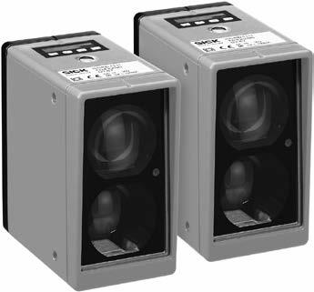
19 Betriebsanleitung Abb. 3: Montage liegend und stehend Montage Empfänger Sender Status-LED (Funktionsanzeige/ Pegelwarnung) Optische Ausrichthilfe (Fadenkreuz) /X056/ SICK AG Deutschland Alle Rechte vorbehalten 19
20 Montage Betriebsanleitung 3.3 Kaskadierung von mehreren Übertragungsstrecken Es können bis zu 2 Übertragungsstrecken in Reihe geschaltet (kaskadiert) werden. 20 SICK AG Deutschland Alle Rechte vorbehalten /X056/
21 Betriebsanleitung Montage 3.4 Elektrischer Anschluss Abb. 4: Anschlussart, PROFIBUS 5-polig, 5-polig, 4-polig, M12, M12, M12 Bus in Bus out /X056/ SICK AG Deutschland Alle Rechte vorbehalten 21
22 Montage Betriebsanleitung Abb. 5: Anschlussart, Ethernet 4-polig, 4-polig, M12, M12 Ethernet 22 SICK AG Deutschland Alle Rechte vorbehalten /X056/
23 Betriebsanleitung Bedienfeld mit LCD- Anzeige 4 Bedienfeld mit LCD- Anzeige 6 Segmente mit 5x7 Pixel Pegelanzeige mit max. 20 Balken (4 Segmente mit 7 Pixeln pro Balken) Mode-Anzeigen mit: RUN, SET, MEN 4 Tasten DOWN, UP, SET, ESC Abb. 6: Bedienfeld /X056/ SICK AG Deutschland Alle Rechte vorbehalten 23
24 Bedienfeld mit LCD- Anzeige 4.1 Menüebene 1 PROFIBUS Betriebsanleitung Abb. 7: Display im Run-Mode bei aktiver Kommunikation 24 SICK AG Deutschland Alle Rechte vorbehalten /X056/
25 Betriebsanleitung Bedienfeld mit LCD- Anzeige 4.2 Menüebene 2 bzw. 3 PROFIBUS /X056/ SICK AG Deutschland Alle Rechte vorbehalten 25
26 Bedienfeld mit LCD- Anzeige 4.3 Parameterliste PROFIBUS Betriebsanleitung Tab. 2: Parameterliste PROFIBUS Be- zeich- nung Auswahl Funktion Align I, E Anzeige Empfangspegel eigene Seite (I ), Gegenseite (E ) Auto On, Off Schaltet die automatische Umstellung der Gegenstelle in den Ausrichtmodus aus. F-Type F1, F2 Auswahl Trägerfrequenz F1 bzw. F2 Baud Übertragungsrate in kbit/s 26 SICK AG Deutschland Alle Rechte vorbehalten /X056/
27 Betriebsanleitung Bedienfeld mit LCD- Anzeige Be- zeich- nung Auswahl Funktion ErrCnt Zähler für Lichtwegunterbrechung (Reset mit SET) RSSI Signaldämpfung in db /X056/ SICK AG Deutschland Alle Rechte vorbehalten 27
28 Bedienfeld mit LCD- Anzeige 4.4 Menüebene 1 Ethernet Betriebsanleitung Abb. 8: Menüebene 1 Ethernet Ethernet-Busstatus Der Ethernet-Busstatus wird durch das RUN-Icon signalisiert: RUN statisch ein: Ethernet-Link OK RUN blinkend: Ethernet-Link OK, geräteinterner Datenpuffer (8 kb) voll, Telegramme werden verworfen RUN aus: Ethernet-Link nicht vorhanden 28 SICK AG Deutschland Alle Rechte vorbehalten /X056/
29 Betriebsanleitung Bedienfeld mit LCD- Anzeige 4.5 Menüebene 2 bzw. 3 Ethernet Abb. 9: Menüebene 2 Ethernet /X056/ SICK AG Deutschland Alle Rechte vorbehalten 29
30 Bedienfeld mit LCD- Anzeige 1) Betriebsanleitung Beim Eintritt in den Menüpunkt wird die aktuell gültige Frequenz zuerst angezeigt. 2) 3) Beim Eintritt in den Menüpunkt wird die aktuell gültige Einstellung zuerst gezeigt. Beim Eintritt in den Menüpunkt wird die aktuell gültige Einstellung zuerst angezeigt. Steht Auto auf ON, wird die automatisch gewählte Konfiguration angezeigt; eine Änderung ist dann nicht möglich. 30 SICK AG Deutschland Alle Rechte vorbehalten /X056/
31 Betriebsanleitung Tab. 3: Parameterliste Ethernet Bedienfeld mit LCD- Anzeige 4.6 Parametrierliste Ethernet Bezeichnung Auswahl Funktion Align I, E Anzeige Empfangspegel eigene Seite (I ), Gegenseite (E ) AUTO ON, OFF Schaltet die automatische Umstellung der Gegenstelle in den Ausrichtmodus aus. F-Type F1, F2 Auswahl Trägerfrequenz F1 bzw. F /X056/ SICK AG Deutschland Alle Rechte vorbehalten 31
32 Bedienfeld mit LCD- Anzeige Betriebsanleitung Bezeichnung Auto Auswahl ON, OFF Funktion Auswahl Autonegotiation aktiv bzw. inaktiv Hinweis: Wenn Auto = ON, zeigen die Parameter "Duplex" und "Speed" die automatisch ermittelten Parameter an. Duplex FD, HD Auswahl Datenfluss Vollduplex bzw. Halbduplex 32 SICK AG Deutschland Alle Rechte vorbehalten /X056/
33 Betriebsanleitung Bedienfeld mit LCD- Anzeige Be- zeich- nung Auswahl Funktion Speed 100, 10 ErrCnt Auswahl Datenrate 100 Mbit/s bzw. 10 Mbit/s Zähler für Lichtwegunterbrechung (Reset mit SET) RSSI Signaldämpfung in db /X056/ SICK AG Deutschland Alle Rechte vorbehalten 33
34 Inbetriebnahme Betriebsanleitung 5 Inbetriebnahme 5.1 Gerätekonfiguration Hinweis Vor Inbetriebnahme ist die Frequenz F1/F2 zu wählen. Die Baudrate (für PROFIBUS) ist an die Baudrate des Busmasters anzupassen (default: 1500 Mbit/s). Bei Ethernet ist defaultmäßig Autonegotiation eingestellt. 34 SICK AG Deutschland Alle Rechte vorbehalten /X056/
35 Betriebsanleitung Inbetriebnahme 5.2 Bus-Terminierung bei PROFIBUS Endet das PROFIBUS-Kabel an der (kein Buskabel an Buchse PROFIBUS out ), ist der Bus mittels eines Terminierungssteckers in der Buchse PROFIBUS out abzuschließen. 5.3 Ausrichtung Üblicherweise stehen sich die Geräte zunächst in der Nahdistanz gegenüber. Nach Anlegen der Versorgungsspannung geht das automatisch in den RUN- Mode über. Besteht die optische Verbindung zum gegenüberliegenden Gerät, wird dies durch die /X056/ SICK AG Deutschland Alle Rechte vorbehalten 35
36 Inbetriebnahme Betriebsanleitung orange Status-LED signalisiert (permanent aktiv) und es können sofort Daten übertragen werden. Fahren Sie mit dem Fahrzeug so weit, bis die Datenübertragung des abbricht und die orange Status-LED blinkt. Die Geräte können jetzt jeweils einzeln nachjustiert werden. Bei zu geringem Empfangspegel muss der gegenüberliegende Sender nachjustiert werden. Im Run-Mode ist die Güte der Ausrichtung des Senders direkt am Bargraph des Empfängers ablesbar. Für eine komfortable Ausrichtung des Senders kann an diesem der ALIGN-Mode aktiviert werden. 36 SICK AG Deutschland Alle Rechte vorbehalten /X056/
37 Betriebsanleitung Inbetriebnahme In der Werkseinstellung "Align"/"AUTO" = "ON" ist danach sowohl der Empfangspegel des gegenüberliegenden Empfängers (E ) als auch des eigenen Empfängers (I ) ohne Wechsel des Standorts ablesbar. Bei guter Ausrichtung müssen die Status- LEDs beider aktiv sein. Zur Weiterfahrt ist in den RUN- Mode zu wechseln und gegebenenfalls die Nachjustierung zu wiederholen. Die optische Ausrichthilfe mit Fadenkreuz erleichtert die Ausrichtung zusätzlich. Nehmen Sie im Nahbereich die Ausrichtung ggfs. mit einem geraden mechanischen Hilfsmittel wie z. B. einer langen Wasserwaage /X056/ SICK AG Deutschland Alle Rechte vorbehalten 37
38 Inbetriebnahme Betriebsanleitung vor, falls die gegenüberliegende ISD über die optische Ausrichthilfe nicht deutlich genug erkennbar sein sollte. Hinweis Im ALIGN-Mode ist keine Buskommunikation möglich. Nach der Inbetriebnahme wird empfohlen den Parameter "Align"/"AUTO" auf "OFF" zu parametrieren. Damit ist gewährleistet, dass bei Kommunikationsstörungen kein automatischer Sprung in den ALIGN-Mode erfolgt. 38 SICK AG Deutschland Alle Rechte vorbehalten /X056/
39 Betriebsanleitung Inbetriebnahme 5.4 Sende-LED über MF- Eingang ausschalten Über den MF-Eingang kann die Sende-LED ausgeschaltet werden. Im ausgeschalteten Zustand blinkt die orange Status-LED und im Display wird "LsrOff" angezeigt. 5.5 Anzeige orange Status-LED Die orange Status-LED gibt Aufschluss über den Betriebsstatus der. Folgende Betriebsstati und Geräteverhalten werden angezeigt: /X056/ SICK AG Deutschland Alle Rechte vorbehalten 39
40 Inbetriebnahme Im RUN-Modus: Betriebsanleitung genügend Pegel -> LED dauerhaft ein Pegel fällt unter Warnschwelle -> LED blinkt, Kommunikation weiter möglich Pegel fällt unter Funktionsschwelle -> LED blinkt, Kommunikation nicht mehr möglich Im ALIGN-Modus: genügend Pegel -> LED dauerhaft ein Pegel fällt unter Warnschwelle -> LED blinkt Pegel fällt unter Funktionsschwelle -> LED dauerhaft aus 40 SICK AG Deutschland Alle Rechte vorbehalten /X056/
41 Betriebsanleitung Technische Daten 6 Technische Daten 6.1 Datenblatt Tab. 4: Datenblatt Allgemeine Daten Lichtquelle 0,2 180 m Infrarot-LED, 850 nm Betriebsreichweite Öffnungswinkel Lichtfleckdurchmesser ± 0,5 1,75 m bei 100 m Entfernung /X056/ SICK AG Deutschland Alle Rechte vorbehalten 41
42 Technische Daten Betriebsanleitung Elektrische Daten Versorgungsspannung U V Stromaufnahme DC V Ohne Heizung max. 0,4 A Mit Heizung max. 1,2 A Schutzklasse Anschluss Stecker M12 Anzeigen/Bedienelemente Optische Ausrichthilfe Status-LED Fadenkreuz Funktionsanzeige und Pegelwarnung (orange) LCD-Anzeige Balkenanzeige für Empfangspegel, Menüführung 42 SICK AG Deutschland Alle Rechte vorbehalten /X056/
43 Betriebsanleitung Technische Daten Bedienung Ausrichtmodus 4 Folientasten, Menüführung Schnittstellen Wählbare Anzeige des internen und externen Empfangspegels über Balkenanzeige Datenschnittstelle Baudrate PROFIBUS Ethernet PROFIBUS Ethernet 9,6, 19,2, 93,75, 187,5, 375, 500, 1500, 3000 kbit/s, einstellbar über Bedientasten 10/100 Mbit/s /X056/ SICK AG Deutschland Alle Rechte vorbehalten 43
44 Technische Daten Betriebsanleitung Signalverzögerung PROFIBUS Signalverzögerung Ethernet Schalteingang MF Schaltausgang Q 1 µs + 2 Tbit 350 µs + Anzahl der Bytes x 8 / 3 Mbit/s U V 2 V: Sende-LED deaktiviert PNP, U V 2 V: störungsfreier Betrieb, I out = 100 ma, kurzschlussfest Mechanische Daten Gehäusematerial Gewicht Metall Ca. 900 g 44 SICK AG Deutschland Alle Rechte vorbehalten /X056/
45 Betriebsanleitung Technische Daten 60 x 105 x 105 mm Schutzart IP 65 Umweltbedingungen Abmessungen Umgebungstemperatur Lagertemperatur C C (mit Heizung) C EMV 1) EN , EN ) Dies ist eine Einrichtung der Klasse A. Diese Einrichtung kann im Wohnbereich Funkstörungen verursachen /X056/ SICK AG Deutschland Alle Rechte vorbehalten 45
46 Technische Daten 6.2 Maßbilder Betriebsanleitung Abb. 10: Maßbild 46 SICK AG Deutschland Alle Rechte vorbehalten /X056/
47 Betriebsanleitung Technische Daten 6.3 Zubehör Anschlusstechnik für PROFIBUS-Schnittstelle PROFIBUS-Abschlusswiderstand Typ Bestell-Nr. PR-STE-END /X056/ SICK AG Deutschland Alle Rechte vorbehalten 47
48 Technische Daten Betriebsanleitung PROFIBUS-Leitungsdose, M12, 5-polig, Bus in Typ Bestell-Nr. PR-DOS-1205-G PROFIBUS-Leitungsstecker, M12, 5-polig, Bus out Typ Bestell-Nr. PR-STE-1205-G SICK AG Deutschland Alle Rechte vorbehalten /X056/
49 Betriebsanleitung Technische Daten PROFIBUS-Leitung, 2 x 0,34 mm 2, Meterware Typ Bestell-Nr. LTG-2102-MW Temperaturbereich Bewegt: C Festverlegt: C Mantel Schirmung PUR violett Ø 8 mm AL-PT-Folie /X056/ SICK AG Deutschland Alle Rechte vorbehalten 49
50 Technische Daten Betriebsanleitung Leitung, Bus in Typ Leitungsdose mit PROFIBUS- DOL-12- PR-G05 DOL-12- PR-G10 Bestell-Nr. Leitungslänge m m 50 SICK AG Deutschland Alle Rechte vorbehalten /X056/
51 Betriebsanleitung Technische Daten Leitung, Bus in Typ Leitungsstecker mit PROFIBUS- STL-12- PR-G05 STL-12- PR-G10 Bestell-Nr. Leitungslänge m m /X056/ SICK AG Deutschland Alle Rechte vorbehalten 51
52 Technische Daten Betriebsanleitung Ethernet Leitung M12 Stecker D-codiert gerade auf RJ45 gerade Typ Bestell-Nr. Leitungslänge SSL-2J04- G03ME SSL-2J04- G05ME SSL-2J04- G10ME SSL-2J04- G25ME m m m m 52 SICK AG Deutschland Alle Rechte vorbehalten /X056/
53 Betriebsanleitung Technische Daten PROFINET Leitung M12 Stecker D- codiert gerade auf RJ45 gerade Typ Bestell-Nr. Leitungslänge SSL-2J04- G02MZ60 SSL-2J04- G05MZ60 SSL-2J04- G10MZ m m m /X056/ SICK AG Deutschland Alle Rechte vorbehalten 53
54 Technische Daten Ausrichtzubehör Betriebsanleitung Ausrichthalterung Typ Bestell-Nr. BEF-DME/ISD SICK AG Deutschland Alle Rechte vorbehalten /X056/
55 Betriebsanleitung Technische Daten Befestigungswinkel Typ BEF-WINK- DME/ISD Bestell-Nr /X056/ SICK AG Deutschland Alle Rechte vorbehalten 55
56 Technische Daten Betriebsanleitung 56 SICK AG Deutschland Alle Rechte vorbehalten /X056/
57 Betriebsanleitung Troubleshooting 7 Troubleshooting Problem Ursache Lösung NoSync (im Display) bzw. Status-LED blinken NoSync (im Display) bzw. Status-LED blinken NoSync (im Display) bzw. Status-LED blinken F1/F2 nicht gewählt Kein Sichtkontakt Baudrate nicht korrekt F1/F2 wählen Ausrichten Baudrate wählen Kein R (im Display) Kein Telegramm von Kupferseite Verkabelung prüfen /X056/ SICK AG Deutschland Alle Rechte vorbehalten 57
58 Troubleshooting Betriebsanleitung Problem Ursache Lösung Kein T (im Display) Kein Telegramm von optischer Seite Verkabelung prüfen Status-LED aus Versorgung fehlt/hardware defekt Status-LED blinkt Kein RUN-Icon (im Display) Versorgung überprüfen/ Gerät austauschen Funktionsreserve Kein Ethernet- Link vorhanden Ausrichtung überprüfen Verkabelung prüfen, Bus- Parameter prüfen RUN-Icon (im Display) blinkt Pufferüberlauf Übertragene Datenmenge reduzieren 58 SICK AG Deutschland Alle Rechte vorbehalten /X056/
59 Betriebsanleitung Troubleshooting Problem Ursache Lösung Keine Datenübertragung vorhanden, SET-Icon im Display aktiv Schlechte Ausrichtung; Gerät ist im Align-Modus Nach Inbetriebnahme den Parameter Align AUTO auf OFF setzen /X056/ SICK AG Deutschland Alle Rechte vorbehalten 59
60 Betriebsanleitung This work is protected by copyright. All rights reserved by SICK AG. Reproduction of this document or parts of this document is only permissible within the limits of the legal determination of Copyright Law. Modification or expurgation of this work is prohibited without the express written permission of SICK AG. 60 SICK AG Deutschland Alle Rechte vorbehalten /X056/
61 Betriebsanleitung Contents Contents 1 About this document Purpose of this document Symbols used Product description Safety notes Safety standard Correct use Device name Principle of operation Supported protocols Signal delay Mounting Mutual interference Mechanical mounting Cascading of multiple transmission lines Electrical connection /X056/ SICK AG Deutschland Alle Rechte vorbehalten 61
62 Contents Betriebsanleitung 4 Control panel with LCD display Menu level 1 (PROFIBUS) Menu levels 2 and 3 PROFIBUS Parameter list PROFIBUS Menu level 1 Ethernet Ethernet bus status Menu level 2 or 3 Ethernet Commissioning Device configuration Bus termination with PROFIBUS Alignment Switch OFF Send LED via MF input Display of the orange status LED SICK AG Deutschland Alle Rechte vorbehalten /X056/
63 Betriebsanleitung Contents 6 Technical data Data sheet Dimensional drawings Accessories Connectivity for PROFIBUS interface Alignment accessories Troubleshooting /X056/ SICK AG Deutschland Alle Rechte vorbehalten 63
64 Kapitel 1 About this document Betriebsanleitung 1 About this document Please read this chapter carefully before you begin working with this documentation and the. 1.1 Purpose of this document These operating instructions are for giving technical personnel of the machine manufacturer or operator instructions on the safe mounting, configuration, electrical installation, commissioning, operation and maintenance of the optical data transmission system. These operating instructions do not provide information on operating the machine in which the optical 64 SICK AG Deutschland Alle Rechte vorbehalten /X056/
65 Betriebsanleitung Kapitel 1 About this document data transmission system is integrated. For information about this, refer to the instruction manual of the respective machine. 1.2 Symbols used Note Take action Notes inform you about special aspects of the device. Instructions for taking action are indicated by an arrow. Read carefully and follow the instructions for action /X056/ SICK AG Deutschland Alle Rechte vorbehalten 65
66 Kapitel 1 About this document Betriebsanleitung WARNING Warning! A warning indicates a specific or potential hazard. This is intended to protect you against accidents. Read carefully and follow the warnings! 66 SICK AG Deutschland Alle Rechte vorbehalten /X056/
67 Betriebsanleitung Kapitel 2 Product description 2 Product description This chapter provides information on the special properties of the. It describes the construction and operating principle of the device, in particular the various operating modes. Always read this chapter before you mount, install and commission the device /X056/ SICK AG Deutschland Alle Rechte vorbehalten 67
68 Kapitel 2 Product description 2.1 Safety notes Betriebsanleitung Safety standard The optical data transmission system has been developed, produced and tested in accordance with the applicable safety standards. It is a state-of-theart device Correct use The optical data transmission system has been designed and developed for optical transmission of data using infrared light. 68 SICK AG Deutschland Alle Rechte vorbehalten /X056/
69 Betriebsanleitung Kapitel 2 Product description WARNING The protection of personnel and the device cannot be guaranteed if the device is operated in a manner not corresponding to its correct use. Areas of application The is suitable for the following areas of application: Automated high-bay warehouses Stationary data transmission between buildings Anywhere, where data transmission to and from stationary or moving objects (visual contact) over relatively long distances (up to 180 m) is required /X056/ SICK AG Deutschland Alle Rechte vorbehalten 69
70 Kapitel 2 Product description 2.2 Device name Betriebsanleitung Tab. 5: Device designation Order No. Heating without with Ethernet Data Device interface name PROFIBUS without with 70 SICK AG Deutschland Alle Rechte vorbehalten /X056/
71 Betriebsanleitung Kapitel 2 Product description 2.3 Principle of operation Fig. 11: Principle of operation To prevent mutual interference when operating in duplex mode, the data transmission system use two different frequency pairs. These are set via the control panel. Both devices monitor the received signal level which can be displayed on a bar graph indicator. If the received level drops below a certain level e.g. due to soiling of the optics, a warning output signal is activated. All work on the device (mounting, connecting, aligning, configuration) /X056/ SICK AG Deutschland Alle Rechte vorbehalten 71
72 Kapitel 2 Product description Betriebsanleitung can be performed from the top of the units. 2.4 Supported protocols The supports the following data protocols: PROFIBUS: PROFIBUS, MPI and PROFIsafe can be transmitted. Ethernet: EtherNet TCP/IP, EtherNet/IP, PROFINET and PROFIsafe can be transmitted. Note When transmitting Ethernet protocols, the maximum optical data transmission rate of 3 Mbit/s, as well as the maximum input and output data buffer of 8 kbyte of the 72 SICK AG Deutschland Alle Rechte vorbehalten /X056/
73 Betriebsanleitung Kapitel 2 Product description should be taken into account. To reduce data traffic, external switches or routers can be used. 2.5 Signal delay The signal delays documented in the appendix "Technical data" may require in borderline cases adjustment of the bus timing parameters in the control /X056/ SICK AG Deutschland Alle Rechte vorbehalten 73
74 Kapitel 3 Mounting Betriebsanleitung 3 Mounting This chapter describes how to prepare and mount the optical data transmission system. The devices can be mounted horizontally or vertically on the bracket. 3.1 Mutual interference Operation of two optical data transmission devices side by side is required in some applications. A minimum distance between the devices must be maintained. 74 SICK AG Deutschland Alle Rechte vorbehalten /X056/
75 Betriebsanleitung Kapitel 3 Mounting d min = s max x tan (0.5 ) d min = Minimum distance Fig. 12: Distances s max = Max. required scanning range When the optical data transmission device is mounted in parallel to a DME distance sensor or DL100 product family, a minimum distance of 100 mm must be /X056/ SICK AG Deutschland Alle Rechte vorbehalten 75
76 Kapitel 3 Mounting Betriebsanleitung maintained (a >100 mm). This minimum distance is independent of the maximum distance between the two ISDs. 3.2 Mechanical mounting Install the devices so the optical axes of the two devices match at minimum distance: Line distance 0.2 to 180 m: Install the two devices facing one another but rotate one through 180. Line distance 3.0 to 180 m: The two devices can be installed without 180 rotation. 76 SICK AG Deutschland Alle Rechte vorbehalten /X056/
77 Betriebsanleitung Kapitel 3 Fig. 13: horizontal and vertical installation Mounting Receiver Sender Status LED (function indicator / level warning) Optical alignment aid (crosshair) /X056/ SICK AG Deutschland Alle Rechte vorbehalten 77
78 Kapitel 3 Mounting Betriebsanleitung 3.3 Cascading of multiple transmission lines Up to 2 transmission lines can be connected in series (cascaded). 78 SICK AG Deutschland Alle Rechte vorbehalten /X056/
79 Betriebsanleitung Kapitel 3 Mounting Fig. 14: Connection type, PROFIBUS 3.4 Electrical connection 5-pin, 5-pin, 4-pin, M12, M12, M12 Bus in Bus out /X056/ SICK AG Deutschland Alle Rechte vorbehalten 79
80 Kapitel 3 Mounting Betriebsanleitung Fig. 15: Connection type, Ethernet 4-pin, 4-pin, M12, M12 Ethernet 80 SICK AG Deutschland Alle Rechte vorbehalten /X056/
81 Betriebsanleitung Kapitel 4 Control panel with LCD display 4 Control panel with LCD display 6 segments with 5x7 pixels Level indicator with max. 20 bars (4 segments with 7 pixels per bar) Mode indicators with: RUN, SET, MEN 4 buttons DOWN, UP, SET, ESC Fig. 16: Control panel /X056/ SICK AG Deutschland Alle Rechte vorbehalten 81
82 Kapitel 4 Control panel with LCD display 4.1 Menu level 1 (PROFIBUS) Betriebsanleitung Fig. 17: Display in Run mode during active communica tion 82 SICK AG Deutschland Alle Rechte vorbehalten /X056/
83 Betriebsanleitung Kapitel 4 Control panel with LCD display 4.2 Menu levels 2 and 3 PROFIBUS /X056/ SICK AG Deutschland Alle Rechte vorbehalten 83
84 Kapitel 4 Control panel with LCD display 4.3 Parameter list PROFIBUS Betriebsanleitung Tab. 6: Parameter list, PROFIBUS Name Selection Function Align I, E Display of reception level own side (I ), opposite side (E ) Auto On, Off Switches off automatic changeover of the remote station to Align mode. F-Type F1, F2 Selection of carrier frequency F1 or F2 Baud 9.6 to 3000 Transmission rate in kbit/s 84 SICK AG Deutschland Alle Rechte vorbehalten /X056/
85 Betriebsanleitung Kapitel 4 Control panel with LCD display Name Selection Function ErrCnt Counter for light beam interruption (reset with SET) RSSI Signal damping in db /X056/ SICK AG Deutschland Alle Rechte vorbehalten 85
86 Kapitel 4 Control panel with LCD display 4.4 Menu level 1 Ethernet Betriebsanleitung Fig. 18: Menu level 1 Ethernet Ethernet bus status The Ethernet bus status is indicated by the RUN icon: RUN static on: Ethernet link OK RUN flashing: Ethernet link OK, device-internal data buffer (8 kb) full, telegrams are discarded RUN off: No Ethernet link 86 SICK AG Deutschland Alle Rechte vorbehalten /X056/
87 Betriebsanleitung Kapitel 4 Fig. 19: Menu level 2 Ethernet Control panel with LCD display 4.5 Menu level 2 or 3 Ethernet /X056/ SICK AG Deutschland Alle Rechte vorbehalten 87
88 Kapitel 4 Control panel with LCD display 4) When you access the menu item, the currently valid frequency is first displayed. Betriebsanleitung 5) 6) When you access the menu item, the currently valid setting is first displayed. When you access the menu item, the currently valid setting is first displayed. If Auto is set to ON, the automatically selected configuration is displayed; then a change is not possible. 88 SICK AG Deutschland Alle Rechte vorbehalten /X056/
89 Betriebsanleitung Kapitel 4 Control panel with LCD display 4.6 Parameter list Ethernet Tab. 7: Parameter list Ethernet Name Selection Function Align I, E Display of reception level own side (I ), opposite side (E ) AUTO ON, OFF Switches off automatic changeover of the remote station to Align mode. F-Type F1, F2 Selection of carrier frequency F1 or F /X056/ SICK AG Deutschland Alle Rechte vorbehalten 89
90 Kapitel 4 Control panel with LCD display Betriebsanleitung Name Auto Selection Function ON, OFF Selection of autonegotiation active or inactive Note: If "Auto" = "ON", the "Duplex" and "Speed" parameters display the automatically determined parameters. Duplex FD, HD Selection of data flow full-duplex or half-duplex Speed 100, 10 Selection of data rate 100 Mbit/s or 10 Mbit/s 90 SICK AG Deutschland Alle Rechte vorbehalten /X056/
91 Betriebsanleitung Kapitel 4 Control panel with LCD display Name ErrCnt Selection Function Counter for light beam interruption (reset with SET) RSSI Signal damping in db /X056/ SICK AG Deutschland Alle Rechte vorbehalten 91
92 Kapitel 5 Commissioning Betriebsanleitung 5 Commissioning 5.1 Device configuration Note Before operating the devices, you must select the frequency F1/F2. Set the data transmission rate for PROFIBUS to the same data transmission rate as the bus master (default: 1500 Mbit/s). For Ethernet, the default is autonegotiation. 92 SICK AG Deutschland Alle Rechte vorbehalten /X056/
93 Betriebsanleitung Kapitel 5 Commissioning 5.2 Bus termination with PROFIBUS If the PROFIBUS cable ends at (no bus cable at the "PROFIBUS out" jack), terminate the bus using a terminator plug in the "PROFIBUS out" jack. 5.3 Alignment The devices are normally first aligned at a close distance. After you connect the supply voltage, the switches into RUN mode automatically. If there is an optical connection to the opposing device, this is indicated by the orange status LED (permanently active) and /X056/ SICK AG Deutschland Alle Rechte vorbehalten 93
94 Kapitel 5 Commissioning data can be transmitted immediately. Betriebsanleitung Move the vehicle until the data transmission of the is interrupted and the orange status LED flashes. The devices can be realigned individually one after another. If there is a low reception level, the opposing sender must be realigned. In Run mode, the quality of the alignment of the sender can be read from the bar graph of the receiver directly. For convenient alignment of the sender, ALIGN mode can be activated on the sender. 94 SICK AG Deutschland Alle Rechte vorbehalten /X056/
95 Betriebsanleitung Kapitel 5 Commissioning In the default setting "Align" / "AUTO" = "ON", both the reception level of the opposing receiver (E ) and current receiver (I ) can be read without a change of location. If the alignment is good, the status LEDs of both devices must be active. Switch to RUN mode to drive on and repeat the realignment if required. The optical alignment aid with crosshairs serves to further simplify the alignment. Use a straight mechanical aid if necessary, e.g. a long bubble level, in close proximity for alignment if the opposing ISD cannot be seen clearly enough via the optical alignment aid /X056/ SICK AG Deutschland Alle Rechte vorbehalten 95
96 Kapitel 5 Note Commissioning Betriebsanleitung No bus communication is possible in ALIGN mode. After commissioning, it is recommended that you set the "Align" / "AUTO" parameter to "OFF". This ensures that ALIGN mode does not automatically start in the event of communication faults. 96 SICK AG Deutschland Alle Rechte vorbehalten /X056/
97 Betriebsanleitung Kapitel 5 Commissioning 5.4 Switch OFF Send LED via MF input The MF input can be used to switch off the Send LED. When OFF, the orange status LED flashes and "LsrOff" appears on the display. 5.5 Display of the orange status LED The orange status LED provides information about the operating status of the. The following operating statuses and device behaviors are displayed: /X056/ SICK AG Deutschland Alle Rechte vorbehalten 97
98 Kapitel 5 Commissioning In RUN mode: Sufficient level -> LED ON continuously Betriebsanleitung Level falls below warning threshold -> LED flashes, communication can continue Level falls below functional threshold -> LED flashes, communication no longer possible In ALIGN mode: Sufficient level -> LED ON continuously Level falls below warning threshold -> LED flashes Level falls below functional threshold -> LED OFF continuously 98 SICK AG Deutschland Alle Rechte vorbehalten /X056/
99 Betriebsanleitung Kapitel 6 Technical data 6 Technical data 6.1 Data sheet Tab. 8: Data sheet General data Operating range Light source Aperture angle Light spot diameter 0.2 to 180 m Infrared LED, 850 nm ± m at 100 m distance /X056/ SICK AG Deutschland Alle Rechte vorbehalten 99
100 Kapitel 6 Technical data Electrical data Supply voltage V s Power consumption Protection class Connection DC 18 to 30 V Betriebsanleitung Without heating max. 0.4 A With heating max. 1.2 A M12 plug Indications/controls Optical alignment aid Status LED LCD display Crosshair Function indicator and level warning (orange) Bar graph for reception level, menu prompting 100 SICK AG Deutschland Alle Rechte vorbehalten /X056/
101 Betriebsanleitung Kapitel 6 Technical data Operation Alignment mode 4 foil keys, menu prompting Selectable display of internal and external reception level via bar graph Interfaces Data interface PROFIBUS Ethernet Data transmission rate PROFIBUS Ethernet 9,6, 19,2, 93,75, 187,5, 375, 500, 1500, 3000 kbit/s, adjustable via operation keys 10/100 MBit/s /X056/ SICK AG Deutschland Alle Rechte vorbehalten 101
102 Kapitel 6 Technical data Signal delay, PROFIBUS Signal delay, Ethernet Switching input MF Switching output Q 1 µs + 2 Tbit Betriebsanleitung 350 µs + No. of bytes x 8 / 3 Mbit/s U V 2 V: Sender LED deactivated PNP, U V 2 V: interference-free operation, I out = 100 ma, short-circuit protected Mechanical data Housing material Weight Dimensions Metal Approx. 900 g 60 x 105 x 105 mm 102 SICK AG Deutschland Alle Rechte vorbehalten /X056/
103 Betriebsanleitung Kapitel 6 Technical data Enclosure rating IP 65 Environmental conditions Ambient temperature Storage temperature 25 to +55 C 40 to +55 C (with heating) 40 to +75 C EMC 2) EN , EN ) This is a Class A device. This device can cause radio interference in residential areas /X056/ SICK AG Deutschland Alle Rechte vorbehalten 103
104 Kapitel 6 Fig. 20: dimensional drawing Technical data 6.2 Dimensional drawings Betriebsanleitung 104 SICK AG Deutschland Alle Rechte vorbehalten /X056/
105 Betriebsanleitung Kapitel 6 Technical data 6.3 Accessories Connectivity for PROFIBUS interface PROFIBUS termination resistor Model name Order No. PR-STE-END /X056/ SICK AG Deutschland Alle Rechte vorbehalten 105
106 Kapitel 6 Technical data PROFIBUS cable socket, M12, 5-pin, Bus in Betriebsanleitung Model name Order No. PR-DOS-1205-G PROFIBUS cable plug, M12, 5-pin, Bus out Model name Order No. PR-STE-1205-G SICK AG Deutschland Alle Rechte vorbehalten /X056/
107 Betriebsanleitung Kapitel 6 Technical data PROFIBUS cable, 2 x 0.34 mm 2, sold by meter Model name Order No. LTG-2102-MW Temperature range Moving: 5 to +80 C Fixed: 40 to +80 C Sheath Shield PUR violet Ø 8 mm AL-PT foil /X056/ SICK AG Deutschland Alle Rechte vorbehalten 107
108 Kapitel 6 Technical data Betriebsanleitung Cable socket with PROFIBUS cable, Bus in Model name Order No. Length of cable DOL-12- PR-G05 DOL-12- PR-G m m 108 SICK AG Deutschland Alle Rechte vorbehalten /X056/
109 Betriebsanleitung Kapitel 6 Technical data Cable plug with PROFIBUS cable, Bus in Model name Order No. Length of cable STL-12- PR-G05 STL-12- PR-G m m /X056/ SICK AG Deutschland Alle Rechte vorbehalten 109
110 Kapitel 6 Technical data Betriebsanleitung Ethernet cable, M12 plug D-coded straight to RJ45 straight Model name Order No. Length of cable SSL-2J04- G03ME SSL-2J04- G05ME SSL-2J04- G10ME SSL-2J04- G25ME m m m m 110 SICK AG Deutschland Alle Rechte vorbehalten /X056/
111 Betriebsanleitung Kapitel 6 Technical data PROFINET cable, M12 plug D-coded straight to RJ45 straight Model name Order No. Length of cable SSL-2J04- G02MZ60 SSL-2J04- G05MZ60 SSL-2J04- G10MZ m m m /X056/ SICK AG Deutschland Alle Rechte vorbehalten 111
112 Kapitel 6 Technical data Alignment accessories Betriebsanleitung Alignment bracket Model name Order No. BEF-DME/ISD SICK AG Deutschland Alle Rechte vorbehalten /X056/
113 Betriebsanleitung Kapitel 6 Technical data Mounting brackets Model name BEF-WINK- DME/ISD Order No /X056/ SICK AG Deutschland Alle Rechte vorbehalten 113
114 Kapitel 6 Technical data Betriebsanleitung 114 SICK AG Deutschland Alle Rechte vorbehalten /X056/
115 Betriebsanleitung Kapitel 7 Troubleshooting 7 Troubleshooting Problem Cause Solution NoSync (on display) or status LED flashing NoSync (on display) or status LED flashing NoSync (on display) or status LED flashing F1/F2 not selected Select F1/F2 No line of sight Aligning Baud rate not correct Select data transmission rate No R (on display) No telegram from copper side Check cabling /X056/ SICK AG Deutschland Alle Rechte vorbehalten 115
116 Kapitel 7 Troubleshooting Betriebsanleitung Problem Cause Solution No T (on display) No telegram from optical side Check cabling Status LED off No power supply/hardwa re defect Check power supply/ Replace device Status LED flashes No RUN icon (on display) Operating reserve No Ethernet link Check alignment Check cabling, check bus parameters RUN icon (on display) flashes Buffer overflow Reduce the volume of data transferred 116 SICK AG Deutschland Alle Rechte vorbehalten /X056/
117 Betriebsanleitung Kapitel 7 Troubleshooting Problem Cause Solution No data transmission, SET icon active on display Poor alignment; device is in Align mode After commissioning, set the "Align" "AUTO" parameter to "OFF" /X056/ SICK AG Deutschland Alle Rechte vorbehalten 117
118 / HS_8M ( ) A4 4c int39 Australia Phone tollfree sales@sick.com.au Belgium/Luxembourg Phone +32 (0) info@sick.be Brasil Phone sac@sick.com.br Canada Phone +1(952) (800) tollfree info@sickusa.com Ceská Republika Phone sick@sick.cz China Phone info.china@sick.net.cn Phone ghk@sick.com.hk Danmark Phone sick@sick.dk Deutschland Phone kundenservice@sick.de España Phone info@sick.es France Phone info@sick.fr Great Britain Phone +44 (0) info@sick.co.uk India Phone info@sick-india.com Israel Phone info@sick-sensors.com Italia Phone info@sick.it Japan Phone +81 (0) support@sick.jp Magyarország Phone office@sick.hu Nederlands Phone +31 (0) info@sick.nl Norge Phone austefjord@sick.no Österreich Phone +43 (0) office@sick.at Polska Phone info@sick.pl România Phone office@sick.ro Russia Phone info@sick.ru Schweiz Phone contact@sick.ch Singapore Phone admin@sicksgp.com.sg Slovenija Phone +386 (0) office@sick.si South Africa Phone info@sickautomation.co.za South Korea Phone /4 info@sickkorea.net Suomi Phone sick@sick.fi Sverige Phone info@sick.se Taiwan Phone sales@sick.com.tw Türkiye Phone +90 (216) info@sick.com.tr United Arab Emirates Phone +971 (0) info@sick.ae USA/México Phone +1(952) (800) tollfree info@sickusa.com More representatives and agencies at SICK AG Waldkirch Germany
ONLINE-DATENBLATT. FX3-MOC000000 Flexi Soft Drive Monitor MOTION CONTROL SICHERHEITS-STEUERUNGEN
 ONLINE-DATENBLATT FX3-MOC000000 Flexi Soft Drive Monitor A B C D E F H I J K L M N O P Q R S T Technische Daten im Detail Merkmale Modul Art der Konfiguration Sicherheitstechnische Kenngrößen Bestellinformationen
Online-Datenblatt. FX3-XTDS84002 Flexi Soft SICHERHEITS-STEUERUNGEN
 Online-Datenblatt FX3-XTDS84002 Flexi Soft A B C D E F H I J K L M N O P Q R S T Technische Daten im Detail Merkmale Modul Art der Konfiguration Sicherheitstechnische Kenngrößen Bestellinformationen Typ
"Programming Tool PGT-05-S for DRS61 Version 1.0 USB interface" "Programming-Tool PGT-05-S für DRS61 Version 1.0 USB Schnittstelle" I.
 "Programming-Tool PGT-05-S für DRS61 Version 1.0 USB Schnittstelle" "Programming Tool PGT-05-S for DRS61 Version 1.0 USB interface" Achtung! Während des Programmiervorganges darf der Encoder nicht an die
RS232-Verbindung, RXU10 Herstellen einer RS232-Verbindung zwischen PC und Messgerät oder Modem und Messgerät
 Betriebsanleitung RS232-Verbindung, RXU10 Herstellen einer RS232-Verbindung zwischen PC und Messgerät oder Modem und Messgerät ä 2 Operating Instructions RS232 Connection, RXU10 Setting up an RS232 connection
Barcodescanner CLV62x / CLV620 / Mid Range
 ONLINE-DATENBLATT www.mysick.com Barcodescanner CLV62x / CLV620 / Mid Range CLV620-0000 Barcodescanner CLV62x / CLV620 / Mid Range Typ > CLV620-0000 Artikelnr. > 1040288 Auf einen Blick CAN, Ethernet TCP/IP,
Einstrahl-Sicherheits-Lichtschranken L41
 ONLINE-DATENBLATT www.mysick.com Einstrahl-Sicherheits-Lichtschranken L41 L41E-33MA2A, L41S-33MA2A Einstrahl-Sicherheits-Lichtschranken L41 Empfänger Typ > L41E-33MA2A Artikelnr. > 6034862 Sender Typ >
ONLINE-DATENBLATT. RTF-M2117 ZoneControl LICHTTASTER UND LICHTSCHRANKEN
 ONLINE-DATENBLATT RTF-M2117 ZoneControl A B C D E F Abbildung kann abweichen Bestellinformationen Typ Artikelnr. RTF-M2117 1063198 Weitere Geräteausführungen und Zubehör www.sick.de/zonecontrol H I J K
Vision-Sensoren Inspector PIM60, Inspector, Inspector PIM-series
 ONLINE-DATENBLATT www.mysick.com Vision-Sensoren Inspector PIM60, Inspector, Inspector PIM-series VSPM-6F2113 Vision-Sensoren Inspector PIM60, Inspector, Inspector PIM-series Typ > VSPM-6F2113 Artikelnr.
UWC 8801 / 8802 / 8803
 Wandbedieneinheit Wall Panel UWC 8801 / 8802 / 8803 Bedienungsanleitung User Manual BDA V130601DE UWC 8801 Wandbedieneinheit Anschluss Vor dem Anschluss ist der UMM 8800 unbedingt auszuschalten. Die Übertragung
Installation Instructions
 EN DE Installation Instructions WLAN Installation Kit, 300 Mbps, 5 GHz, 16 dbi AK-4 Wireless Kit Scope of delivery Junction box AK-4 (1x) 1 Connection board AK-4 CB with 12VDC power supply unit (1x) 2
ONLINE-DATENBLATT. RFMS Pro TRACK-AND-TRACE-SYSTEME
 ONLINE-DATENBLATT RFMS Pro A B C D E F H I J K L M N O P Q R S T Technische Daten im Detail Merkmale Frequenzband MTBF MTTR Applikationen Einsatzgebiet Performance Anzahl der Codes pro Lesetor Bestellinformationen
LMS100 Lasermesssensor Laser Measurement Sensor
 TECHNISCHE INFORMATION TECHNICAL INFORMATION LMS100 Lasermesssensor Laser Measurement Sensor Ergänzung zur Betriebanleitung LMS100 (ab Firmware V1.60) Supplement to the LMS100 Operating Instructions (from
CABLE TESTER. Manual DN-14003
 CABLE TESTER Manual DN-14003 Note: Please read and learn safety instructions before use or maintain the equipment This cable tester can t test any electrified product. 9V reduplicated battery is used in
Online-Datenblatt FLOWSIC200 STRÖMUNGSGESCHWINDIGKEITS-MESSGERÄTE
 Online-Datenblatt A B C D E F H I J K L M N O P Q R S T Bestellinformationen Einsatzbereiche Messung in Straßen- und Eisenbahntunneln Zur Steuerung der Tunnelventilation Zur Erkennung der Rauchausbreitung
p^db=`oj===pìééçêíáåñçêã~íáçå=
 p^db=`oj===pìééçêíáåñçêã~íáçå= Error: "Could not connect to the SQL Server Instance" or "Failed to open a connection to the database." When you attempt to launch ACT! by Sage or ACT by Sage Premium for
LMS12x/LMS13x Security Lasermesssensoren
 TECHNISCHE INFORMATION LMS12x/LMS13x Security Lasermesssensoren Ergänzung zur Errichteranleitung Security (Nr. 8014486) Inhalt Inhalt 1 EasyTeach... 3 1.2 Lite... 3 1.3 Pro... 4 1.3.1 Ablauf... 5 1.3.2
TomTom WEBFLEET Tachograph
 TomTom WEBFLEET Tachograph Installation TG, 17.06.2013 Terms & Conditions Customers can sign-up for WEBFLEET Tachograph Management using the additional services form. Remote download Price: NAT: 9,90.-/EU:
Cable Tester NS-468. Safety instructions
 Cable Tester NS-468 Safety instructions Do not use the cable tester NS-468 if it is damaged. This device is only for use inside dry and clean rooms. This device must be protected from moisture, splash
GmbH, Stettiner Str. 38, D-33106 Paderborn
 Serial Device Server Der Serial Device Server konvertiert die physikalische Schnittstelle Ethernet 10BaseT zu RS232C und das Protokoll TCP/IP zu dem seriellen V24-Protokoll. Damit können auf einfachste
E/A-Bedieneinheit. I/O Control unit 658552 DE/GB 08/02
 E/A-Bedieneinheit I/O Control unit 527429 658552 DE/GB 08/02 Best.-Nr.: 658552 Benennung: DATENBLATT Bezeichnung: D:LP-BED.EINH.-E/A-DE/GB Stand: 08/2002 Autoren: Christine Löffler Grafik: Doris Schwarzenberger
CONTROLLER RECEIVER REPEATER PAIRING SLIM CLIP
 ANLEITUNGEN // INSTRUCTIONS CONTROLLER RECEIVER REPEATER PAIRING SLIM CLIP BEDIENUNGSANLEITUNG // INSTRUCTION MANUAL MONTAGEANLEITUNG // ASSEMBLY INSTRUCTION MONTAGEANLEITUNG // ASSEMBLY INSTRUCTION KOPPLUNG
Batterie-Identifikations-Modul EL-BIM
 Bedienungs- und Montageanleitung Batterie-Identifikations-Modul EL-BIM 1.0 Allgemeines Das Batterie-Identifikations-Modul EL-BIM ermöglicht eine eindeutige Zuordnung von Ladevorgang und Batterie in den
Online-Datenblatt MCS100FT CEMS-LÖSUNGEN
 Online-Datenblatt MCS100FT A B C D E F H I J K L M N O P Q R S T 15267 14181 certified certified Bestellinformationen Typ MCS100FT Weitere Geräteausführungen und Zubehör Einsatzbereiche Emissionsüberwachung
ALL1681 Wireless 802.11g Powerline Router Quick Installation Guide
 ALL1681 Wireless 802.11g Powerline Router Quick Installation Guide 1 SET ALL1681 Upon you receive your wireless Router, please check that the following contents are packaged: - Powerline Wireless Router
How-To-Do. Hardware Configuration of the CC03 via SIMATIC Manager from Siemens
 How-To-Do Hardware Configuration of the CC03 via SIMATIC Manager from Siemens Content Hardware Configuration of the CC03 via SIMATIC Manager from Siemens... 1 1 General... 2 1.1 Information... 2 1.2 Reference...
1. General information... 2 2. Login... 2 3. Home... 3 4. Current applications... 3
 User Manual for Marketing Authorisation and Lifecycle Management of Medicines Inhalt: User Manual for Marketing Authorisation and Lifecycle Management of Medicines... 1 1. General information... 2 2. Login...
Parameter-Updatesoftware PF-12 Plus
 Parameter-Updatesoftware PF-12 Plus Mai / May 2015 Inhalt 1. Durchführung des Parameter-Updates... 2 2. Kontakt... 6 Content 1. Performance of the parameter-update... 4 2. Contact... 6 1. Durchführung
Optik Konverter für Profibus Optical converter for Profibus
 Lichtwellenleiter Koverter Optical fibres converters Optik Konverter für Profibus Optical converter for Profibus Technische Daten Technical data Versorgungsspannung: 5V DC Supply voltage: 5V DC Stromaufnahme:
Schnell-Start-Anleitung Quick Start Guide
 Schnell-Start-Anleitung Quick Start Guide 3 1. Cube anschließen Schließen Sie den Cube an die Stromversorgung an. Verbinden Sie den Cube mit dem Router. Die Power- und die Internet-LED beginnen zu blinken,
rs232 DIN rail adapter für Thyro-s, thyro-a und thyro-ax
 1 rs232 DIN rail adapter für Thyro-s, thyro-a und thyro-ax August 2014 DE/EN - V2 2 INHALTSVERZEICHNIS Ansprechpartner 3 1. Einleitung 4 2. Lieferumfang 4 3. Merkmale 4 4. Anschlüsse 5 5. Inbetriebnahme
Load balancing Router with / mit DMZ
 ALL7000 Load balancing Router with / mit DMZ Deutsch Seite 3 English Page 10 ALL7000 Quick Installation Guide / Express Setup ALL7000 Quick Installation Guide / Express Setup - 2 - Hardware Beschreibung
Online-Datenblatt MEAC CEMS-LÖSUNGEN
 Online-Datenblatt MEAC MEAC A B C D E F H I J K L M N O P Q R S T Bestellinformationen Typ MEAC Artikelnr. Auf Anfrage Die genauen Gerätespezifikationen und Leistungsdaten des Produkts können abweichen
Aufgabenstellung Mit welchen SICLOCK Produkten kann ich einen PC Zeitsynchronisieren?
 SICLOCK Application Note AN-0005 Titel Synchronisation von PCs mit SICLOCK Aufgabenstellung Mit welchen SICLOCK Produkten kann ich einen PC Zeitsynchronisieren? Schlüsselwörter SICLOCK DCFRS, WinGPS, GPS1000,
Technology for you. Media Solutions
 Technology for you Media Solutions Media Units / Media Units Media Units Robuste Installationstechnik für jeden Klassenund Schulungsraum Robust installation technology for each class- and conference room
Nachdem Sie die Datei (z.b. t330usbflashupdate.exe) heruntergeladen haben, führen Sie bitte einen Doppelklick mit der linken Maustaste darauf aus:
 heruntergeladen haben, führen Sie bitte einen Doppelklick mit der linken Maustaste darauf aus:") Deutsch 1.0 Vorbereitung für das Firmwareupdate Vergewissern Sie sich, dass Sie den USB-Treiber für Ihr Gerät installiert haben. Diesen können Sie auf unserer Internetseite unter www.testo.de downloaden.
Deutsch 1.0 Vorbereitung für das Firmwareupdate Vergewissern Sie sich, dass Sie den USB-Treiber für Ihr Gerät installiert haben. Diesen können Sie auf unserer Internetseite unter www.testo.de downloaden.
p^db=`oj===pìééçêíáåñçêã~íáçå=
 p^db=`oj===pìééçêíáåñçêã~íáçå= How to Disable User Account Control (UAC) in Windows Vista You are attempting to install or uninstall ACT! when Windows does not allow you access to needed files or folders.
iid software tools QuickStartGuide iid USB base RFID driver read installation 13.56 MHz closed coupling RFID
 iid software tools QuickStartGuide iid software tools USB base RFID driver read installation write unit 13.56 MHz closed coupling RFID microsensys Jun 2013 Introduction / Einleitung This document describes
Technische Daten Technical data
 Technische Technical PLVario-NET E3010000 PLVario-NET E3010001 PLVario-NET/MBUS E3010002 PLVario-NET/MODBUS/RTU E3010003 PLVario-NET/AE E3010004 PLVario-NET/AE/MBUS E3010005 PLVario-NET/AE/MODBUS/RTU bus
Technisches Datenblatt Technical Data Sheet 3160-00-00.73A4B. Signalwandler für 4 analoge Eingangssignale 4-20mA auf CAN
 Seite/Page 1 von/of 5 MultiXtend CAN 3160-00-00.73A4B Signalwandler für 4 analoge Eingangssignale 4-20mA auf CAN Signal converter for four Thermocouple Type J converting to CAN-Bus Beschreibung Description
Leister SYSTEM SINGLE PATCH MODULE SPM 01
 D GB Leister SYSTEM SINGLE PATCH MODULE SPM 01 Leister Process Technologies Galileo-Strasse 10 CH-05 Kaegiswil/Switzerland Tel. +41-41 4 4 Fax +41-41 4 1 www.leister.com sales@leister.com Einbauanleitung
LWL Transceiver 9 x 1 SIP 650nm
 LWL Transceiver 9 x 1 SIP 650nm Bild/Pic. 1 1 Allgemeine Beschreibung Der 9 x 1 Transceiver ist speziell geeignet für Anwendungen mit dem 1mm Standard- Kunststofflichtwellenleiter. Bestückt mit einer schnellen
User Manual Bedienungsanleitung. www.snom.com. snom Wireless Headset Adapter snom Schnurlos-Headset-Adapter. English. Deutsch
 English snom Wireless Headset Adapter snom Schnurlos-Headset-Adapter Deutsch User Manual Bedienungsanleitung 2007 snom technology AG All rights reserved. Version 1.00 www.snom.com English snom Wireless
CAN-Bus RPM adapter. User Manual Anwender-Beschreibung
 CAN-Bus RPM adapter COT02 User Manual Anwender-Beschreibung Stand: 12.02.03 GRABAU Computertechnik GmbH Elsener Str. 30 33102 Paderborn Tel: +49 5251 1367-0 Fax: +49 5251 1367-30 Email: info@grabau.de
Das Modul kann thermische oder 3-stufige Aktoren regeln, wie auch vier 0-10 VDC analoge Ausgänge.
 Das ist ein I/O Modul für Modbus, das vier Ni1000-LG Eingänge oder vier Digitaleingänge lesen kann. Jeder individuelle Eingang kann so eingestellt werden, das er als analoger oder digitaler Eingang arbeitet.
BLK-2000. Quick Installation Guide. English. Deutsch
 BLK-2000 Quick Installation Guide English Deutsch This guide covers only the most common situations. All detail information is described in the user s manual. English BLK-2000 Quick Installation Guide
Robotino View Kommunikation mit OPC. Communication with OPC DE/EN 04/08
 Robotino View Kommunikation mit OPC Robotino View Communication with OPC 1 DE/EN 04/08 Stand/Status: 04/2008 Autor/Author: Markus Bellenberg Festo Didactic GmbH & Co. KG, 73770 Denkendorf, Germany, 2008
Sensors Monitoring Systems
 Sensors Monitoring Systems Dr.E.Horn GmbH Im Vogelsang 1 71101 Schönaich Germany Tel: +49 7031 6302-0 info@dr-horn.org DK 002629 Rev: 2 01.07.2015 1 /14 Absolut-Drehgeber Absolut-Encoder EGD50.5X und EGD50.7X
BA63 Zeichensätze/ Character sets
 BA63 Zeichensätze/ Character sets Anhang/ Appendix We would like to know your opinion on this publication. Ihre Meinung/ Your opinion: Please send us a copy of this page if you have any contructive criticism.
SmartClass Firmware-Update Vorgehensweise
 Benutzeranweisungen SmartClass Firmware-Update Vorgehensweise 2008.01 (V 1.x.x) Deutsch Please direct all enquiries to your local JDSU sales company. The addresses can be found at: www.jdsu.com/tm-contacts
300Mbps Wireless Outdoor PoE Access Point/Bridge Quick Installation Guide
 LevelOne WAB-5120 300Mbps Wireless Outdoor PoE Access Point/Bridge Quick Installation Guide English Deutsch - 1 - Table of Content English... - 3 - Deutsch... - 9 - This guide covers only the most common
Release Notes BRICKware 7.5.4. Copyright 23. March 2010 Funkwerk Enterprise Communications GmbH Version 1.0
 Release Notes BRICKware 7.5.4 Copyright 23. March 2010 Funkwerk Enterprise Communications GmbH Version 1.0 Purpose This document describes new features, changes, and solved problems of BRICKware 7.5.4.
Technical Information
 Firmware-Installation nach Einbau des DP3000-OEM-Kits Dieses Dokument beschreibt die Schritte die nach dem mechanischen Einbau des DP3000- OEM-Satzes nötig sind, um die Projektoren mit der aktuellen Firmware
Anleitung zur Schnellinstallation TFM-560X YO.13
 Anleitung zur Schnellinstallation TFM-560X YO.13 Table of Contents Deutsch 1 1. Bevor Sie anfangen 1 2. Installation 2 Troubleshooting 6 Version 06.08.2011 1. Bevor Sie anfangen Packungsinhalt ŸTFM-560X
E asyline by Hama GmbH & Co KG Postfach 80 86651 Monheim/Germany Tel. +49 (0)9091/502-0 Fax +49 (0)9091/502-274 hama@hama.de www.hama.
9091/502-0 Fax +49 (0)9091/502-274 hama@hama.de www.hama.") 00021024-10.06 E asyline by Hama GmbH & Co KG Postfach 80 86651 Monheim/Germany Tel. +49 (0)9091/502-0 Fax +49 (0)9091/502-274 hama@hama.de www.hama.com Gamepad Thunderstorm II 0021024 l Bedienungsanleitung
00021024-10.06 E asyline by Hama GmbH & Co KG Postfach 80 86651 Monheim/Germany Tel. +49 (0)9091/502-0 Fax +49 (0)9091/502-274 hama@hama.de www.hama.com Gamepad Thunderstorm II 0021024 l Bedienungsanleitung
NEWSLETTER. FileDirector Version 2.5 Novelties. Filing system designer. Filing system in WinClient
 Filing system designer FileDirector Version 2.5 Novelties FileDirector offers an easy way to design the filing system in WinClient. The filing system provides an Explorer-like structure in WinClient. The
 Information & Montageanleitung Information & Mounting instructions lassic Performance Premium 90 mm Module Halogen H7 12V ES / 1BL 009 999-... LES / EE 1ML 009 999-... US / SAE 1BL 009 999-... 24V ES /
- Messdaten herunterladen - Diagnosis and Analysis of measuring data. - Download of measuring data
 Smart Utility Software The SmartUtility offers the following functionalities: - Search of SmartCheck within the network - Administration of the SmartCheck Software zur Administration von FAG SmartCheck
EtherNet/IP Topology and Engineering MPx06/07/08VRS
 EtherNet/IP Topology and Engineering MPx06/07/08VRS 3 1. Engineering via free EtherNet/IPTM-Port of a device on Bus from MPx07V10 2. Engineering via optional Industrial-Ethernet-Switch 3. Engineering via
Quick Start Guide. VN8810 Wireless Interface for CAN/LIN/K Line and DoIP Version 1.0 English / Deutsch
 Quick Start Guide VN8810 Wireless Interface for CAN/LIN/K Line and DoIP Version 1.0 English / Deutsch ENGLISH Quick Start Guide VN8810 1 ENGLISH 1.1 Installation Please use the drivers from the included
Softwareupdate-Anleitung // AC Porty L Netzteileinschub
 1 Softwareupdate-Anleitung // AC Porty L Netzteileinschub Softwareupdate-Anleitung // AC Porty L Netzteileinschub HENSEL-VISIT GmbH & Co. KG Robert-Bunsen-Str. 3 D-97076 Würzburg-Lengfeld GERMANY Tel./Phone:
v i r t u A L C O M P o r t s
 v i r t u A L C O M P o r t s (HO720 / HO730) Installieren und Einstellen Installation and Settings Deutsch / English Installieren und Einstellen des virtuellen COM Ports (HO720 / HO730) Einleitung Laden
Montageanleitung Konverter RS422 - USB
 Montageanleitung Konverter RS422 - USB Messanordnung für Sensoren der Reihe ILD 1302 / 1402 / 1700 / 2200 / 2300 PC PC1402-X/I PC1402-X/U PC1700-X PC2200-5 PC2300-X/OE PC2300-X/SUB-D + PC2300-0,5/Y TB1
mit integriertem Frequenzumrichter with integrated frequency converter
 Sektionaltorantriebe 1 / W1 mit externer Steuerung 1 / W1 with external controls mit integrierter Steuerung with integrated controls 1FU-I mit integriertem Frequenzumrichter 1FU-I with integrated frequency
miditech 4merge 4-fach MIDI Merger mit :
 miditech 4merge 4-fach MIDI Merger mit : 4 x MIDI Input Port, 4 LEDs für MIDI In Signale 1 x MIDI Output Port MIDI USB Port, auch für USB Power Adapter Power LED und LOGO LEDs Hochwertiges Aluminium Gehäuse
FOR ENGLISCH VERSION PLEASE SCROLL FORWARD SOME PAGES. THANK YOU!
 FOR ENGLISCH VERSION PLEASE SCROLL FORWARD SOME PAGES. THANK YOU! HELPLINE GAMMA-SCOUT ODER : WIE BEKOMME ICH MEIN GERÄT ZUM LAUFEN? Sie haben sich für ein Strahlungsmessgerät mit PC-Anschluss entschieden.
KURZANLEITUNG. Firmware-Upgrade: Wie geht das eigentlich?
 KURZANLEITUNG Firmware-Upgrade: Wie geht das eigentlich? Die Firmware ist eine Software, die auf der IP-Kamera installiert ist und alle Funktionen des Gerätes steuert. Nach dem Firmware-Update stehen Ihnen
Shock pulse measurement principle
 Shock pulse measurement principle a [m/s²] 4.0 3.5 3.0 Roller bearing signals in 36 khz range Natural sensor frequency = 36 khz 2.5 2.0 1.5 1.0 0.5 0.0-0.5-1.0-1.5-2.0-2.5-3.0-3.5-4.0 350 360 370 380 390
NVR Mobile Viewer for iphone/ipad/ipod Touch
 NVR Mobile Viewer for iphone/ipad/ipod Touch Quick Installation Guide DN-16111 DN-16112 DN16113 2 DN-16111, DN-16112, DN-16113 for Mobile ios Quick Guide Table of Contents Download and Install the App...
TVHD800x0. Port-Weiterleitung. Version 1.1
 TVHD800x0 Port-Weiterleitung Version 1.1 Inhalt: 1. Übersicht der Ports 2. Ein- / Umstellung der Ports 3. Sonstige Hinweise Haftungsausschluss Diese Bedienungsanleitung wurde mit größter Sorgfalt erstellt.
Instruktionen Mozilla Thunderbird Seite 1
 Instruktionen Mozilla Thunderbird Seite 1 Instruktionen Mozilla Thunderbird Dieses Handbuch wird für Benutzer geschrieben, die bereits ein E-Mail-Konto zusammenbauen lassen im Mozilla Thunderbird und wird
 Software-SPS: Software PLC: Vom Industrie-PC fähigen From industrial PCzur to leistungs high-performance Steuerung controller Zur Visualisierung und Bedienung von PCs are used in countless machines and
Cisco SSPA122. Installation und manuelle Rekonfiguration. Dokumentenversion 1
 Cisco SSPA122 Installation und manuelle Rekonfiguration Dokumentenversion 1 Placetel UC-One Cisco SPA122 Installation und manuelle Rekonfiguration Copyright Hinweis Copyright 2015 finocom AG Alle Rechte
150Mbps Micro Wireless N USB Adapter
 150Mbps Micro Wireless N USB Adapter TEW-648UBM ŸAnleitung zur Schnellinstallation (1) ŸTroubleshooting (6) 1.11 1. Bevor Sie anfangen Packungsinhalt ŸTEW-648UBM ŸCD-ROM (Dienstprogramm & Bedienungsanleitung)
ONLINE LICENCE GENERATOR
 Index Introduction... 2 Change language of the User Interface... 3 Menubar... 4 Sold Software... 5 Explanations of the choices:... 5 Call of a licence:... 7 Last query step... 9 Call multiple licenses:...
Emotron VS10/VS30 AC drive
 Emotron VS10/VS30 AC drive Diagnosemodule, Blindkappe Diagnostic modules, Blankingcover Montageanleitung Mounting Instructions Allgemeines 1 Erst lesen, dann beginnen 1 Allgemeines 1.1 Erst lesen, dann
Installationsanweisung Installation Instructions Notice d installation. Instrucciones de montaje Istruzioni per l installazione. Programm Update.
 Installationsanweisung Installation Instructions Notice d installation Instrucciones de montaje Istruzioni per l installazione Programm Update für FWA510 / FWA515 Program update for FWA510 / FWA515 1 2
Signal Processing LWL-Sender/Empfänger mit Outdoor-Box für die störsichere Übertragung von Rechtecksignalen
 LWL-Sender/Empfänger mit Outdoor-Box für die störsichere Übertragung von Rechtecksignalen LWL Sender/Empfänger mit Outdoor-Box Merkmale LWL-SBR, Übertragungsweiten bis zu 1500 m Wandlung üblicher Rechtecksignale
Anschlusskabel Connecting Cables
 Anschlusskabel Connecting Cables Made in Germany Made in Germany Sichere Verbindungstechnik Safe connection method D 27.0813de www.di-soric.com di-soric Anschlusskabel sind die optimale Lösung, um alle
Fleet Manager 100 Bedienungsanleitung User Manual Hardware
 Bedienungsanleitung User Manual Hardware 1. Bedienung im Fahrzeug... 2 2. Signale des Bordcomputers (LED, Summer)... 4 3. Fehlersuche... 5 1. Operation in the vehicle... 7 2. Buzzer codes... 9 3. Troubleshooting...
M-Bus Micro-Master USB
 M-Bus Micro-Master USB Der M-Bus Micro-Master USB ist eine Weiterentwicklung des bewährten Micro-Masters mit RS232C-Schnittstelle für den Einsatz an den USB-Schnittstellen moderner PC s und Laptops. Das
German English Firmware translation for T-Sinus 154 Access Point
 German English Firmware translation for T-Sinus 154 Access Point Konfigurationsprogramm Configuration program (english translation italic type) Dieses Programm ermöglicht Ihnen Einstellungen in Ihrem Wireless
EMCO Installationsanleitung Installation instructions
 EMCO Installationsanleitung Installation instructions Installationsanleitung Installation instructions Digitalanzeige digital display C40, FB450 L, FB600 L, EM 14D/17D/20D Ausgabe Edition A 2009-12 Deutsch...2
ReadMe zur Installation der BRICKware for Windows, Version 6.1.2. ReadMe on Installing BRICKware for Windows, Version 6.1.2
 ReadMe zur Installation der BRICKware for Windows, Version 6.1.2 Seiten 2-4 ReadMe on Installing BRICKware for Windows, Version 6.1.2 Pages 5/6 BRICKware for Windows ReadMe 1 1 BRICKware for Windows, Version
Titelbild1 ANSYS. Customer Portal LogIn
 Titelbild1 ANSYS Customer Portal LogIn 1 Neuanmeldung Neuanmeldung: Bitte Not yet a member anklicken Adressen-Check Adressdaten eintragen Customer No. ist hier bereits erforderlich HERE - Button Hier nochmal
TRANSMITTER SPECIFICATION / SENDER SPEZIFIKATIONEN RECEIVER SPECIFICATION / EMPFÄNGER SPEZIFIKATIONEN
 TRANSMITTER SPECIFICATION / SENDER SPEZIFIKATIONEN Channels: 2 Model type: car/boat RF power: less than 20 dbm Code type: digital Sensitivity: 1024 Low voltage warning:yes (less than 4,5 V) DSC port: yes
GAMING HEADSET LX16 PRO
 GAMING HEADSET LX6 PRO CHAT GAME Content Inhalt Lioncast LX6 Pro gaming headset Lioncast LX6 Pro Gaming Headset Inline remote kabelgebundene Fernbedienung MUTE - MIC - ON XBOX PS PS PC RCA splitter cable
Quick Start Guide RED 10
 Quick Start Guide RED 10 Sophos Access Points 1. Preparation Note: Before you begin, please make sure that you have a working Internet connection. Congratulations on your purchase of the Sophos RED security
Frequently asked Questions for Kaercher Citrix (apps.kaercher.com)
") Frequently asked Questions for Kaercher Citrix (apps.kaercher.com) Inhalt Content Citrix-Anmeldung Login to Citrix Was bedeutet PIN und Token (bei Anmeldungen aus dem Internet)? What does PIN and Token
Frequently asked Questions for Kaercher Citrix (apps.kaercher.com) Inhalt Content Citrix-Anmeldung Login to Citrix Was bedeutet PIN und Token (bei Anmeldungen aus dem Internet)? What does PIN and Token
Bedienungsanleitung User Manual KAAN SIM III
 Bedienungsanleitung User Manual KAAN SIM III Einführung Introduction Vielen Dank, dass Sie sich für ein KOBIL Smart Card Terminal entschieden haben. Mit dem KOBIL KAAN SIM III haben Sie ein leistungsfähiges
Außenknauf Innenkanuf Profilzylinder
 DATENBLATT BCM Offline-Leser BCM Elektronischer Knaufzylinder FL IP55 Set AA/BB Anwendungsbereich Konformität Identifikation max. Anzahl Betätigungen mit einem Batteriesatz 35.000 Benutzerführung Batterien
C R 2025 C LOSE PUSH OPEN
 3V C R 2025 C LOSE PUSH OPEN ) ) ) 25 222 3V C R 2025 C LOSE PUSH OPEN 25 222 3V C R 2025 C LOSE PUSH OPEN 25 222 Den här symbolen på produkten eller i instruktionerna betyder att den elektriska
Kurzanleitung um Transponder mit einem scemtec TT Reader und der Software UniDemo zu lesen
 Kurzanleitung um Transponder mit einem scemtec TT Reader und der Software UniDemo zu lesen QuickStart Guide to read a transponder with a scemtec TT reader and software UniDemo Voraussetzung: - PC mit der
Technical Documentation and Operation Manual. Kühlgehäuse der Pyrometerserie Metis Cooling jacket for pyrometer series Metis (KG10-00)
") Beschreibung und Bedienungsanleitung Technical Documentation and Operation Manual Kühlgehäuse der Pyrometerserie Metis Cooling jacket for pyrometer series Metis (KG10-00) Inhalt S./P. 1. Beschreibung /
Beschreibung und Bedienungsanleitung Technical Documentation and Operation Manual Kühlgehäuse der Pyrometerserie Metis Cooling jacket for pyrometer series Metis (KG10-00) Inhalt S./P. 1. Beschreibung /
PA-CONTROL CANopen Fehlerliste Ab Version 5.15 Ausgabe: 06/2008 Art.-Nr.:1082211. Technische Dokumentation
 Technische Dokumentation PA-CONTROL CANopen Fehlerliste Ab Version 5.15 Ausgabe: 06/2008 Art.-Nr.:1082211 IEF Werner GmbH Wendelhofstr. 6 78120 Furtwangen Tel.: 07723/925-0 Fax: 07723/925-100 www.ief-werner.de
Quick Start Guide RED 50
 Quick Start Guide RED 50 RED 50 Sophos RED Appliances Before you begin, make sure you have a working Internet connection. 1. Preparing the installation Congratulations on your purchase of the Sophos RED
Installationshinweise Z501J / Z501K Adapter IrDa USB Installation hints Z501J / Z501K Adapter IrDa USB
 Installationshinweise Z501J / Z501K Adapter IrDa USB Installation hints Z501J / Z501K Adapter IrDa USB 1/3.04 (Diese Anleitung ist für die CD geschrieben. Wenn Sie den Treiber vom WEB laden, entpacken
Der Adapter Z250I / Z270I lässt sich auf folgenden Betriebssystemen installieren:
 Installationshinweise Z250I / Z270I Adapter IR USB Installation hints Z250I / Z270I Adapter IR USB 06/07 (Laden Sie den Treiber vom WEB, entpacken Sie ihn in ein leeres Verzeichnis und geben Sie dieses
DECKMA. GmbH. Decksmaschinen und Automation Vertriebs GmbH BEDIENUNGSANLEITUNG FÜR GENERAL ALARM SYSTEM USER MANUAL FOR GENERAL ALARM SYSTEM GAS 3000
 DECKMA GmbH Decksmaschinen und Automation Vertriebs GmbH BEDIENUNGSANLEITUNG FÜR GENERAL ALARM SYSTEM USER MANUAL FOR GENERAL ALARM SYSTEM GAS 3000 VERSION 26-November-2007 BEDIENUNGSANLEITUNG Generalalarm