XT 1090 CROSSTRAINER
|
|
|
- Monica Heinrich
- vor 8 Jahren
- Abrufe
Transkript

1 XT 1090 CROSSTRAINER Mod. A25 / A26 GB D CZ SK H
2 Table of contents - Inhaltsverzeichnis - Obsah - Obsah - Tájékoztató 1. English 2. Deutsch 3. Česky. 4. Slovensky 5. Magyar. P 3 P 27 P 52 P 76 P 100 The owner s manual is only for the customer reference. ENERGETICS can not guarantee for mistakes occurring due to translation or change in technical specification of the product. Die Gebrauchsanweisung dient nur zur Referenz für den Kunden. ENERGETICS übernimmt keine Haftung für Fehler die durch Übersetzung oder technische Änderungen des Produkts entstehen. Návod k použití je pouze doporučení pro zákazníky. ENERGETICS nepřebírá žádné ručení za chyby způsobené překladem či změnami v technické specfikaci výrobku. Návod je určený len pre potrebu zákazníkov. ENERGETICS nezodpovedá za chyby, ktoré sa môžu vyskytnúť kvôli chybnému prekladu alebo zmenám v technickej špecifikácii produktu. A használati útmutató kizárólag felhasználói referenciaként szolgál. az ENERGETICS nem vállal felelősséget a fordítási hibákból vagy a termék műszaki módosításaiból eredő hibákért. Copyright by ENERGETICS 2

3 GB Dear Customer, Congratulations on your purchase of an ENERGETICS home exerciser. This product has been designed and manufactured to meet the needs and requirements of in-home use. Please carefully read the instructions prior to assembly and first use. Be sure to keep the instructions for reference and/ or maintenance. If you have any further questions, please contact us. We wish you lots of success and fun while training, Your Team Warranty ENERGETICS offers high quality home exercisers that have been tested and certified according to European Norm EN 957. ENERGETICS warrants to the original purchaser 2 years against possible defects in material and workmanship. Excluded are damages caused by misuse and wearing parts. All electronic parts are warranted for a period of 1 year. The warranty period starts at the date the product was purchased (retain your sales receipt). Safety Instructions Consult your physician before starting with any exercise programme to receive advice on the optimal training. Warning: incorrect/ excessive training can cause health injuries. Stop using the home exerciser when feeling uncomfortable. Ensure that training only starts after correct assembly, adjustment and inspection of the home exerciser. Always start with a warm-up session. Only use original ENERGETICS parts as delivered (see checklist). Follow the steps of the assembly instruction carefully. Only use suitable tools for assembly and ask for assistance if necessary. Place the home exerciser on an even, non-slippery surface. For all adjustable parts be aware of the maximum position to which they can be adjusted. Tighten all adjustable parts to prevent sudden movement while training. This product is designed for adults. Please ensure that children only use it under the supervision of an adult. Ensure that those present are aware of possible hazards, e.g. movable parts during training. The resistance level can be adjusted to your personal preference. Do not use the home exerciser without shoes or loose shoes. Ensure that sufficient space is available to use the home exerciser. Be aware of non-fixed or moving parts whilst mounting or dismounting the home exerciser. To protect the floor or carpet from damage, place a mat under the Elliptical Trainer. Turn off the power whilst the Elliptical Trainer is not in use. Ensure that an area of 2000 x 1000 mm behind the Elliptical Trainer is free from any obstacles. This product is made for home use only and tested up to a maximum body weight of 135 kilograms. We take no responsibility for personal injury or damage sustained by or through the use of this Elliptical Trainer 3

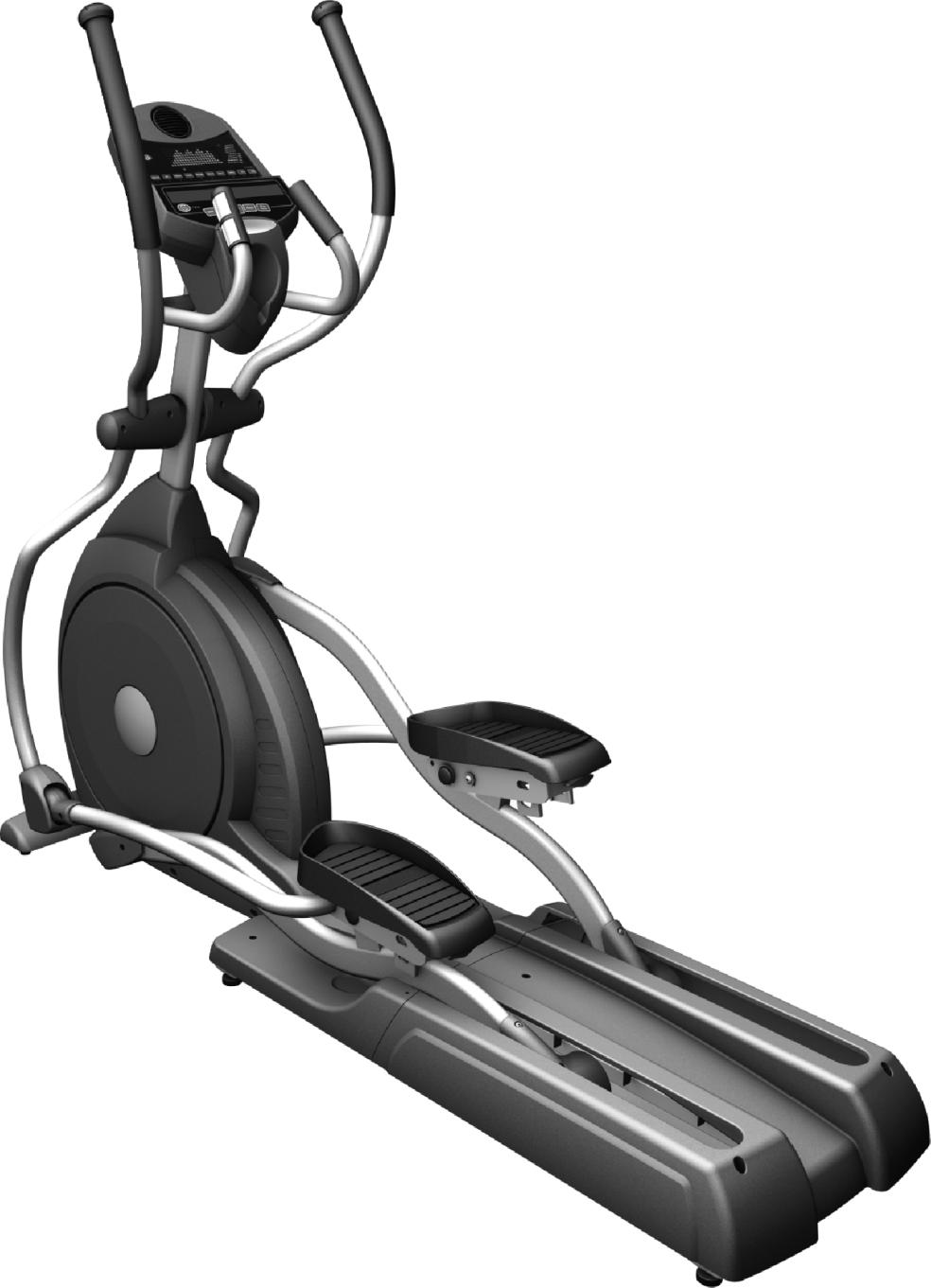
4 Fan (Mod A25) Model A26 w/o Fan Console Handpulse Beverage Holder Handlebar Handlebar Cover Console Mast Console Mast Cover Pedal Front Stabilizer Cover Adjustment Pin Connecting Arm Pedal Arm Rear Shroud Cushion Foot Pad 4

5 Checklist Step 1 #96.3/8" x 19 x 1.5T Flat Washer (2pcs) #104.3/8" x 23 x 2.0T Curved Washer (4pcs) #82 M5 x 15m/m Phillips Head Screw (2pcs) #75.3/8 x 2-1/4 Hex Head Bolt (2pcs) #77. 3/8 x 3-3/4 Hex Head Bolt (4pcs) Step 2 #85. M5 x 12m/m Phillips Head Screw (4pcs) #128.3/8" x 2.0T Split Washer (1pc) #104.3/8" x 23 x 2.0T Curved Washer (2pcs) #76. 3/8 x 3/4 Hex Head Bolt (2pcs) #75.3/8 x 2-1/4 Hex Head Bolt (1pc) 5
 #128.3/8\" x 2.0T Split Washer (1pc) #104.3/8\" x 23 x 2.")
6 Step 3 #102.ψ25 Wave Washer (2 pcs) #131.3/8" x 30 x 2.0T Flat Washer (2 pcs) # x 12m/m Sheet Metal Screw (8 pcs) #76. 3/8 x 3/4 Hex Head Bolt (2 pcs) Step 4 # x 12m/m Sheet Metal Screw (8 pcs) # x 16m/m Tapping Screw (2 pcs) #155.5/16" x 20 x 1.5T Flat Washer (2 pcs) #82. M5 x 15m/m Phillips Head Screw (12 pcs) #91. 5/16" x 7T Nyloc Nut (2 pcs) #79. 5/16 x 1-1/4 Hex Head Bolt (2 pcs) #123. M5 x 50m/m Phillips Head Screw (2 pcs) 6
 #91. 5/16\" x 7T Nyloc Nut (2 pcs) #79.")
7 Tools #126. Phillips Head Screw Driver (1 pc) #125. Short Phillips Head Screw Driver (1 pc) # m/m Wrench (2 pcs) # /14m/m Wrench (1 pc) 7
 #124.")
8 Assembly Unpacking the Unit Carefully remove all parts from carton and inspect for any damage or missing parts. If damaged parts are found, or parts are missing, contact your dealer immediately. Locate the hardware package. The hardware is separated into steps. Remove the tools first. Remove the hardware for each step as needed to avoid confusion. Step 1 REAR RAIL ASSEMBLY 1. Put the 2pcs of 3/ T Flat Washers (96) on the 2pcs of 3/8 2-1/4 Hex Head Bolts (75) and hand-tighten them, through the Top of the Rear Stabilizer Tube (Main Frame), into the Rear Assembly (2) by using the 13/14 m/m Wrench (124). 2. Put the 4pcs of 3/8 23 2T Curved Washers (104) on the 4pcs of 3/8 3-3/4 Hex Head Bolts (77) and hand-tighten them through the Front of the Rear Stabilizer Tube (Main Frame), into the Rail Assembly (2) by using 13/14 m/m Wrench (124). 3. Then install Front Stabilizer Cover (59) with 2pcs of M5 15 m/m Phillips Head Screws (82) by using the Phillips head screw driver (126). 8
 on the 2pcs of 3/8 2-1/4 Hex Head Bolts (75) and hand-tighten them, through the Top of the Rear Stabilizer Tube (Main Frame), into the Rear Assembly (2) by using the 13/14 m/m")
9 Step 2 1. Locate the Console Mast (12) and Console Mast Cover (49) and slide the Cover onto the Mast as far as it will go. Make sure the Console Mast Cover (49) is facing the correct way. 2. At the top opening of the Main Frame (1), there is a Computer Cable (39) tied with a guiding wire. Unravel the wire and feed the Computer Cable (39) it into the bottom of the Console Mast tube (12) and out of the top opening. 3. Install the Console Mast (12) into the receiving bracket on the top of the Main Frame (1). NOTE: there is one bolt already installed in the receiving bracket that will engage with the slot at the bottom of the Console Mast. This needs to be tightened at the end along with the three other console mast bolts. 4. Put the 1pc of 3/8" x 2T Split Washer (128) onto the 1pc of 3/8" x 2-1/4" Hex Head Bolt (75) and the 2pcs of 3/8 x 23 x 2T Curved Washers (104) onto the 2pcs of 3/8" x 3/4" Hex Head Bolts (76). Install, and hand tighten them. The 3/8" x 2-1/4" Hex Head Bolt (75) should go through the left side of the receiving bracket into the Console Mast (12). NOTE: The Computer Cable (39) runs through the Console Mast tube (12). Be careful not to damage or pinch this cable during this procedure. Be careful as damage to the Console Assembly (32) could result. Install, and hand tighten the 2pcs of 3/8" x 3/4"Hex Head Bolts (76) with 3/8 x 23 x 2T Curved Washers (104) through the front of the receiving bracket into the Console Mast (12). 5. Use the 13/14m/m Wrench (124) to tighten the three bolts, together with the pre-installed screw, firmly. These bolts should be tightened as much as you possibly can. 6. Locate the Console (32) and tighten it with the 4pcs of M5 10 m/m Phillips Head Screws (85) by using the Phillips Head Screw Driver (126). 7. There are 3pcs connectors at the top opening of the Console Mast (12), two Handpulse W/Cable Assembly (44) and one Computer Cable (39). Connect these to the mating connectors on the back of the Console (32). Do not force them while connecting as the connectors are keyed so that you cannot plug them in the wrong way. 8. Store the excessive cables back into the Console Mast (12) and carefully install the Console (32) onto the mounting plate of Console Mast (12) and secure the 4pcs of M5 x 10m/m Phillips Head Screws (85) by using Philips head screw driver (126). 9

10 Step 3 HANDLE BAR ASSEMBLY 1. Install the 2pcs of Ø25 Wave Washers (102) onto the Handle Bars (10,11) axle. 2. Slide the Left and Right Handle Bars (10,11) onto the appropriate side of the axle. 3. Put the 2pcs of 3/ T Flat Washers (131) onto the 2pcs of 3/8 3/4 Hex Head Bolts (76) and install, and tighten by using the 13/14m/m Wrench (124) in the threaded holes in the ends of the axle. 4. Install the Front Handle Bar Cover (L)(68) and Rear Handle Bar Cover (L)(68~1) onto the Handle Bar (L)(10) with the 4pcs ofø3.5x12m/m Sheet Metal Screws (107) by using the Phillips Head Screw Driver (126). 5. Install the Front Handle Bar Cover (R)(69) and Rear Handle Bar Cover (R)(69~1) onto the Handle Bar (R)(11) with the 4pcs of Ø3.5x12m/m Sheet Metal Screws (107) by using the Phillips Head Screw Driver (126). 10
 by using the Phillips Head Screw Driver (126). 5.")
11 Step 4 1. Align the hole in the end of the Connecting Arms (L&R)(8&9)(pivoting rod end) with the hole in the bracket of the Handle Bars (L&R)(10&11). The rod end should be inside of the Handle Bars (L&R)(10&11) bracket. Take 2pcs of 5/16" x 1-1/4" Hex Head Bolts (79) and install it through the Handle Bar (L&R)(10&11) bracket and the rod end. Install 2pcs of 5/16" x 20 x 1.5T Flat Washers (155), 5/16" x 7T Nyloc Nuts (91) and Fisheye Sleeve (22) on the 5/16" x 1-1/4" Hex Head Bolt (79) and tighten firmly by using 12m/m Wrench (129) and 13/14 m/m Wrench (124) on the 5/16" x 7T Nyloc Nut (91) and on the 5/16" x 1-1/4" Hex Head Bolt (79). 2. Match Connecting Arm Cover B (R)(163), with Connecting Arm Cover B (L)(164), for both sides of connecting arms and tighten with 2pcs of M5 x 15m/m Phillips Head Screws (82) and 4pcs of Ø3.5x12m/m Sheet Metal Screws (107) by using Short Phillips Head Screw Driver (125) 3. Repeat step 1 for the Connecting Arm (R)(9). 4. Match the Connecting Arm Cover A (R) (161), with Connecting Arm Cover A (L) (162), onto the Handle Bar (L) (10) and secure the covers with 2pcs of M5 x 15m/m Phillips Head Screws (82) and 2pcs of Ø3.5x12m/m Sheet Metal Screws (107) by using the Phillips Head Screw Driver(126). 5. Repeat step 3 for the Handle Bar (R) (11). 6. Install the 2pcs of Sliding Wheel Cover (64) above the Slide Wheel, Urethane (47) and Pedal Arm (L, R)(6,7) with the 4pcs of M5x12m/m Phillips Head Screws (82) and tighten them by using Phillips Head Screw Driver (126). 7. Install the Rear Cover (A) (60), on the Rear Stabilizer of the Main Frame (1), with the openings facing backward, and tighten the 2pcs of M5x15m/m Phillips Head Screws (82) by using the Phillips Head Screw Driver (126). 8. Install the Rear Shroud (B) (61), above the Rail Assembly (2), with the openings facing the Rear Shroud (A) (60), and guide the Sliding Wheel (47) into the Rear Shroud (B) (61). 9. Match the openings of Rear Shroud (B) (61), with Rail Assembly Cover (A) (60) and secure both covers with 2pcs of 5x16m/m Tapping Screws (109) by using Philips Head Screw Driver (126). Secure the Rear Shroud (B) (61), at the rear end with 2pcs of M5 x 50m/m Philips Head Screws (123). PLEASE LOCK ALL COMPONENTS UP AFTER THE ACCESSSORIES HAVE BEEN ASSEMBLED. 11
, 5/16\" x 7T Nyloc Nuts (91) and Fisheye Sleeve (22) on the 5/16\" x 1-1/4\" Hex Head Bolt (79) and tighten firmly by using 12m/m Wrench (129) and 13/14 m/m Wrench (124) on the")
12 Notice to avoid injury The foot plates on your new elliptical have a pull-pin adjustment. This adjustment allows you to change the angle of the footpad to add variety to your workouts. The foot plates are spring loaded, and when the pull-pin is pulled, the foot plate can drop suddenly. To avoid any injury please do not put your hand, or any other body part, under the foot plate when pulling the pull-pin. Only place your hand under the very rear of the foot plate, just above the pull-pin. Transport The elliptical is equipped with two transport wheels which are engaged when rear of it is lifted. 12

13 Computerinstruction Fan (Mod. A25) Mod. A26 w/o Fan Display view Program Buttons Dot Matrix Heart rate Indicator Heart rate bar graph Control keys Display view Fan Power switch (Mod. A25) Message window Pulse sensors Power up The Elliptical is supplied with an external power supply. When power is connected to the Elliptical, the console will automatically power up. If there is no input to the console for 20 minutes the console will go to stand-by mode. In stand-by mode the console display will turn off. To turn the console on press any key. When initially powered on the console will perform an internal self test. During this time all the lights will turn on. When the lights go off the dot matrix display will show a software version (ie: VER 1.0) and the message window will display an odometer reading. The odometer reading displays how many hours the elliptical has been used and how many virtual miles the elliptical has gone. The display will look like this: ODO 123 MI 123 HRS. The odometer will remain displayed for only a few seconds then the console will go to the start up display. The dot matrix display will be scrolling through the different profiles of the programs and the message window will be scrolling the start up message. You may now begin to use the console. 13

14 Quick Start This is the quickest way to start a workout. After the console powers up you just press the Start key to begin, this will initiate the Quick Start mode. In Quick Start the Time will count up from zero and the workload may be adjusted manually by pressing the Up or Down buttons. The dot matrix display will have only the bottom row lit at first. As you increase the work load more rows will light indicating a harder workout. The elliptical will get harder to pedal as the rows increase. Basic information The Dot Matrix has two display modes: When you begin a program it will be in the Profile display mode. To the left of the dot matrix there is a button labeled Display. Pressing this button once will switch the display to show a quarter mile track. If the Display button is pressed again the Track indicator light, next to the Display button, will start to blink. This indicates the display is in Scan mode. The display will switch back and forth between Track and Profile mode every few seconds. To turn off the scan mode press the Display key again. This will return you to the profile display mode. The Message Window will initially be displaying Time and Distance information. On the bottom left of the message window is another Display button. Each time this Display button is pressed the next set of information will appear, four windows in all. In order: Time and Distance, Pulse and Calories, Speed in RPM and MPH, Work Level and Watts. If the Display button is pressed during the Level and Watts display the Scan light will come on and the message window will show each set of data for four seconds then switch to the next set of data in a continuous loop. Pressing the Display button again will bring you back to the beginning. To the right of the Dot matrix display on the elliptical is a Heart Icon and a Bar Graph. The elliptical has a built in heart rate monitoring system. Simply grasping the hand pulse sensors on the stationary handle bars, or wearing the heart rate transmitter, will start the Heart Icon blinking (this may take a few seconds). The Message Window will display your heart rate, or Pulse, in beats per minute. The Bar Graph represents the percentage of your maximum heart rate you are currently achieving. NOTE: You must enter your age for the Bar Graph to be accurate. Refer to Heart Rate section for details about these features and how they can help you work out more efficiently. The Stop/Reset button actually has several functions. Pressing the Stop/Reset key once during a program will Pause the program for 5 minutes. If you need to get a drink, answer the phone or any of the many things that could interrupt your workout, this is a great feature. To resume your workout during Pause just press the Start key. If the Stop/Reset button is pressed twice during a workout the program will end and the console will return to the start up screen. If the Stop/Reset key is held down for 3 seconds the console will perform a complete Reset. During data entry for a program the Stop/Reset key performs a Previous Screen function. This allows you to go back one step in the programming each time you press the Stop/Reset key. The Program Keys are used to preview each program. When you first turn the console on you may press each program key to preview what the program profile looks like. If you decide that you want to try a program, press the corresponding program key and then press the Enter key to select the program and enter into the data setting mode. The program keys also act as a Number Key Pad when you are in the data setting mode. Under each program key is a number. If you are setting new data, such as Age, weight etc., you can use these keys to enter the numbers quickly. The consoles include a built-in fan to help keep you cool. To turn the fan on, flip the switch on the right side of the console case (only on Mod. A25). Each of the programs can be customized with your personal information and changed to suit your needs. Some of the information asked for is necessary to ensure the readouts are correct. You will be asked for your Age and Weight. Entering your Age ensures that the Heart Rate bar graph shows the correct number. Your Age is also necessary during the Heart Rate control programs to ensure the correct settings are in the program for your Age. Otherwise the work settings could be too high or low for you. Entering your Weight aides in calculating a more correct Calorie reading. Although we cannot provide an exact calorie count we do want to be as close as possible. 14

15 A message about Calories: Calorie readings on every piece of exercise equipment, whether it is in a gym or at home, are not accurate and tend to vary widely. They are meant only as a guide to monitor your progress from workout to workout. The only way to measure your calorie burn accurately is in a clinical setting connected to a host of machines. This is because every person is different and burns calories at a different rate. Some good news is that you will continue to burn calories at about the same rate as during exercise for minutes after you have finished exercising! Entering/Changing Settings When you enter a program, by pressing a program key, then enter key, you have the option of entering your own personal settings. If you want to workout without entering new settings then just press the Start key. This will bypass the programming of data and take you directly to the start of your workout. If you want to change the personal settings then just follow the instructions in the message window. If you start a program without changing the settings the default, or saved, settings will be used. The default computer settings are: Age = 35, Weight = 155 Lbs., Time = 30:00, Max Level, each program has a different maximum work level: Hill = 7, Fatburn = 5, Cardio = 7, Strength = 8, Interval = 7. NOTE: Age and Weight default settings will change when you enter a new number. So the last Age and Weight entered will be saved as the new default settings. If you enter your Age and Weight the first time you use the Elliptical you will not have to enter it every time you work out unless either your Age or Weight changes or someone else enters a different Age and Weight. Manual The Manual program works as the name implies; manually. This means that you control the work load yourself and not the computer. To start the Manual program follow the instructions below or just press the Manual button then the Enter button and follow the directions in the message window. 1. Press the Manual key then press the Enter key. 2. The message window will ask you to enter your Age. You may enter your Age, using the Up and Down keys or the numeric key pad, then press the Enter key to accept the new number and proceed on to the next screen. 3. You are now asked to enter your Weight. You may adjust the Weight number using the Up and Down keys or the numeric key pad, then press enter to continue. 4. Next is Time. You may adjust the Time and press enter to continue. 5. Now you are finished editing the settings and can begin your workout by pressing the Start key. You can also go back and modify your settings by pressing the Enter key. NOTE: At any time during the editing of Data you can press the Stop key to go back one level, or screen. 6. Once the program starts you will be at level one. This is the easiest level and it is a good idea to stay at level one for a while to warm up. If you want to increase the work load at any time press the Up key; the Down key will decrease the work load. 7. During the Manual program you will be able to scroll through the data in the message window by pressing the adjacent Display key, switch between the profile display and a quarter mile track by pressing the Display key adjacent to the matrix, use the heart rate monitoring features and can switch to heart rate Auto-Pilot mode (See Heart Rate section for details of this feature). 8. When the program ends you may press Start to begin the same program again or Stop to exit the program or you can save the program you just completed as a custom user program by pressing a User key and following the instructions in the message window. 15

16 Preset Programs The Elliptical has five different programs that have been designed for a variety of workouts. These five programs have factory preset profiles for achieving different goals. The initial built-in level of difficulty for each program is set to a relatively easy level. You may adjust the level of difficulty for each program before beginning by following the instructions in the message window after selecting your program. The PROGRAM HILL The Hill program simulates going up and down a hill. The resistance in the pedals will steadily increase and then decrease during the program. To start the Hill program follow the instructions below or just press the Hill button then the Enter button and follow the directions in the message window. 1. Press the Hill key then press the Enter key. 2. The message window will ask you to enter your Age. You may enter your Age, using the Up and Down keys or the numeric key pad, then press the Enter key to accept the new number and proceed on to the next screen. 3. You are now asked to enter your Weight. You may adjust the Weight number using the Up and Down keys or the numeric key pad, then press enter to continue. 4. Next is Time. You may adjust the Time and press enter to continue. 5. Now you are asked to adjust the Max Level. This is the peak exertion level you will experience during the program, at the top of the hill. The factory setting is level seven. Adjust the level and then press enter. 6. Now you are finished editing the settings and can begin your workout by pressing the Start key. You can also go back and modify your settings by pressing the Enter key. NOTE: At any time during the editing of Data you can press the Stop key to go back one level, or screen. 7. If you want to increase or decrease the work load at any time during the program press the Up or Down key. This will only affect the workload for the present position in the profile. When the profile changes to the next column it will return to the preset work level. 8. During the Hill program you will be able to scroll through the data in the message window by pressing the adjacent Display key, switch between the profile display and a quarter mile track by pressing the Display key adjacent to the matrix, use the heart rate monitoring features and can switch to heart rate Auto-Pilot mode. (See Heart Rate section for details of this feature). 9. When the program ends you may press Start to begin the same program again or Stop to exit the program or you can save the program you just completed as a custom user program by pressing a User key and following the instructions in the message window. 16

17 Fat Burn The Fat Burn program is designed, as the name implies, to maximize the burning of fat. There are many schools of thought on the best way to burn fat but most experts agree that a lower exertion level which stays steady is the best. The absolute best way to burn fat is to keep your heart rate at around 60% to 70% of it s maximum potential. This program does not use heart rate but simulates a lower, steady, exertion workout. To start the Fat Burn program follow the instructions below or just press the Fat Burn button then the Enter button and follow the directions in the message window. 1. Press the Fat Burn key then press the Enter key. 2. The message window will ask you to enter your Age. You may enter your Age, using the Up and Down keys or the numeric key pad, then press the Enter key to accept the new number and proceed on to the next screen. 3. You are now asked to enter your Weight. You may adjust the Weight number using the Up and Down keys or the numeric key pad, then press enter to continue. 4. Next is Time. You may adjust the Time and press enter to continue. 5. Now you are asked to adjust the Max Level. This is the peak exertion level you will experience during the program. The factory setting is level five. Adjust the level and then press enter. 6. Now you are finished editing the settings and can begin your workout by pressing the Start key. You can also go back and modify your settings by pressing the Enter key. NOTE: At any time during the editing of Data you can press the Stop key to go back one level, or screen. 7. If you want to increase or decrease the work load at any time during the program press the Up or Down key. This will only affect the workload for the present position in the profile. When the profile changes to the next column it will return to the preset work level. 8. During the Fat Burn program you will be able to scroll through the data in the message window by pressing the adjacent Display key, switch between the profile display and a quarter mile track by pressing the Display key adjacent to the matrix, use the heart rate monitoring features and can switch to heart rate Auto-Pilot mode (See Heart Rate section for details of this feature). 9. When the program ends you may press Start to begin the same program again or Stop to exit the program or you can save the program you just completed as a custom user program by pressing a User key and following the instructions in the message window. 17

18 Cardio The Cardio program is designed to increase your Cardio vascular function. This is, simply said, exercise for your heart and lungs. It will build up your heart muscle and increase blood flow and lung capacity. This is achieved by incorporating a higher level of exertion with slight fluctuations in work. To start the Cardio program follow the instructions below or just press the Cardio button then the Enter button and follow the directions in the message window. 1. Press the Cardio key then press the Enter key. 2. The message window will ask you to enter your Age. You may enter your Age, using the Up and Down keys or the numeric key pad, then press the Enter key to accept the new number and proceed on to the next screen. 3. You are now asked to enter your Weight. You may adjust the Weight number using the Up and Down keys or the numeric key pad, then press enter to continue. 4. Next is Time. You may adjust the Time and press enter to continue. 5. Now you are asked to adjust the Max Level. This is the peak exertion level you will experience during the program. The factory setting is level seven. Adjust the level and then press enter. 6. Now you are finished editing the settings and can begin your workout by pressing the Start key. You can also go back and modify your settings by pressing the Enter key. NOTE: At any time during the editing of Data you can press the Stop key to go back one level, or screen. 7. If you want to increase or decrease the work load at any time during the program press the Up or Down key. This will only affect the workload for the present position in the profile. When the profile changes to the next column it will return to the preset work level. 8. During the Cardio program you will be able to scroll through the data in the message window by pressing the adjacent Display key, switch between the profile display and a quarter mile track by pressing the Display key adjacent to the matrix, use the heart rate monitoring features and can switch to heart rate Auto-Pilot mode. (See Heart Rate section for details of this feature). 9. When the program ends you may press Start to begin the same program again or Stop to exit the program or you can save the program you just completed as a custom user program by pressing a User key and following the instructions in the message window. 18

19 Strength The Strength program is designed to increase muscular strength in your lower body. This program will steadily increase in resistance to a high level and then keeps you there. This is designed to strengthen and tone your legs and glutes. To start the Strength program follow the instructions below or just press the Strength button then the Enter button and follow the directions in the message window. 1. Press the Strength key then press the Enter key. 2. The message window will ask you to enter your Age. You may enter your Age, using the Up and Down keys or the numeric key pad, then press the Enter key to accept the new number and proceed on to the next screen. 3. You are now asked to enter your Weight. You may adjust the Weight number using the Up and Down keys or the numeric key pad, then press enter to continue. 4. Next is Time. You may adjust the Time and press enter to continue. 5. Now you are asked to adjust the Max Level. This is the peak exertion level you will experience during the program. The factory setting is level eight. Adjust the level and then press enter. 6. Now you are finished editing the settings and can begin your workout by pressing the Start key. You can also go back and modify your settings by pressing the Enter key. NOTE: At any time during the editing of Data you can press the Stop key to go back one level, or screen. 7. If you want to increase or decrease the work load at any time during the program press the Up or Down key. This will only affect the workload for the present position in the profile. When the profile changes to the next column it will return to the preset work level. 8. During the Strength program you will be able to scroll through the data in the message window by pressing the adjacent Display key, switch between the profile display and a quarter mile track by pressing the Display key adjacent to the matrix, use the heart rate monitoring features and can switch to heart rate Auto-Pilot mode (See Heart Rate section for details of this feature). 9. When the program ends you may press Start to begin the same program again or Stop to exit the program or you can save the program you just completed as a custom user program by pressing a User key and following the instructions in the message window. 19

20 Interval The Interval program takes you through high levels of intensity followed by periods of low intensity. This program increases your endurance by depleting your oxygen level followed by periods of recovery to replenish oxygen. Your cardio vascular system gets programmed to use oxygen more efficiently this way. To start the Interval program follow the instructions below or just press the Interval button then the Enter button and follow the directions in the message window. 1. Press the Interval key then press the Enter key. 2. The message window will ask you to enter your Age. You may enter your Age, using the Up and Down keys or the numeric key pad, then press the Enter key to accept the new number and proceed on to the next screen. 3. You are now asked to enter your Weight. You may adjust the Weight number using the Up and Down keys or the numeric key pad, then press enter to continue. 4. Next is Time. You may adjust the Time and press enter to continue. 5. Now you are asked to adjust the Max Level. This is the peak exertion level you will experience during the program. The factory setting is level seven. Adjust the level and then press enter. 6. Now you are finished editing the settings and can begin your workout by pressing the Start key. You can also go back and modify your settings by pressing the Enter key. NOTE: At any time during the editing of Data you can press the Stop key to go back one level, or screen. 7. If you want to increase or decrease the work load at any time during the program press the Up or Down key. This will only affect the workload for the present position in the profile. When the profile changes to the next column it will return to the preset work level. 8. During the Interval program you will be able to scroll through the data in the message window by pressing the adjacent Display key, switch between the profile display and a quarter mile track by pressing the Display key adjacent to the matrix, use the heart rate monitoring features and can switch to heart rate Auto-Pilot mode (See Heart Rate section for details of this feature). 9. When the program ends you may press Start to begin the same program again or Stop to exit the program or you can save the program you just completed as a custom user program by pressing a User key and following the instructions in the message window. 20

CABLE TESTER. Manual DN-14003
 CABLE TESTER Manual DN-14003 Note: Please read and learn safety instructions before use or maintain the equipment This cable tester can t test any electrified product. 9V reduplicated battery is used in
Softwareupdate-Anleitung // AC Porty L Netzteileinschub
 1 Softwareupdate-Anleitung // AC Porty L Netzteileinschub Softwareupdate-Anleitung // AC Porty L Netzteileinschub HENSEL-VISIT GmbH & Co. KG Robert-Bunsen-Str. 3 D-97076 Würzburg-Lengfeld GERMANY Tel./Phone:
Parameter-Updatesoftware PF-12 Plus
 Parameter-Updatesoftware PF-12 Plus Mai / May 2015 Inhalt 1. Durchführung des Parameter-Updates... 2 2. Kontakt... 6 Content 1. Performance of the parameter-update... 4 2. Contact... 6 1. Durchführung
p^db=`oj===pìééçêíáåñçêã~íáçå=
 p^db=`oj===pìééçêíáåñçêã~íáçå= Error: "Could not connect to the SQL Server Instance" or "Failed to open a connection to the database." When you attempt to launch ACT! by Sage or ACT by Sage Premium for
Magic Figures. We note that in the example magic square the numbers 1 9 are used. All three rows (columns) have equal sum, called the magic number.
 have equal sum, called the magic number.") Magic Figures Introduction: This lesson builds on ideas from Magic Squares. Students are introduced to a wider collection of Magic Figures and consider constraints on the Magic Number associated with such
Magic Figures Introduction: This lesson builds on ideas from Magic Squares. Students are introduced to a wider collection of Magic Figures and consider constraints on the Magic Number associated with such
Contact 1600 QUICK REFERENCE GUIDE GUIDE D UTILISATION BEDIENUNGSANLEITUNG GUÍA DE REFERENCIA RÁPIDA GUIDA RAPIDA. www.sonybiz.net CHANGING THE WAY
 Contact 1600 CHANGING THE WAY QUICK REFERENCE GUIDE GUIDE D UTILISATION BEDIENUNGSANLEITUNG BUSINESS GUÍA DE REFERENCIA RÁPIDA GUIDA RAPIDA COMMUNICATES www.sonybiz.net GB Getting started STEP 1 Turning
KURZANLEITUNG. Firmware-Upgrade: Wie geht das eigentlich?
 KURZANLEITUNG Firmware-Upgrade: Wie geht das eigentlich? Die Firmware ist eine Software, die auf der IP-Kamera installiert ist und alle Funktionen des Gerätes steuert. Nach dem Firmware-Update stehen Ihnen
https://portal.microsoftonline.com
 Sie haben nun Office über Office365 bezogen. Ihr Account wird in Kürze in dem Office365 Portal angelegt. Anschließend können Sie, wie unten beschrieben, die Software beziehen. Congratulations, you have
Tube Analyzer LogViewer 2.3
 Tube Analyzer LogViewer 2.3 User Manual Stand: 25.9.2015 Seite 1 von 11 Name Company Date Designed by WKS 28.02.2013 1 st Checker 2 nd Checker Version history Version Author Changes Date 1.0 Created 19.06.2015
BRUUDT Kennzeichenhalter für die Honda NC750X ab 2016 BRUUDT Tail Tidy for the Honda NC750X 2016 and onwards.
 Montageanleitung Mounting instructions BRUUDT Kennzeichenhalter für die Honda NC750X ab 2016 BRUUDT Tail Tidy for the Honda NC750X 2016 and onwards. Noch einmal vielen Dank, dass Sie sich für unsere Produkte
miditech 4merge 4-fach MIDI Merger mit :
 miditech 4merge 4-fach MIDI Merger mit : 4 x MIDI Input Port, 4 LEDs für MIDI In Signale 1 x MIDI Output Port MIDI USB Port, auch für USB Power Adapter Power LED und LOGO LEDs Hochwertiges Aluminium Gehäuse
Readme-USB DIGSI V 4.82
 DIGSI V 4.82 Sehr geehrter Kunde, der USB-Treiber für SIPROTEC-Geräte erlaubt Ihnen, mit den SIPROTEC Geräten 7SJ80/7SK80 über USB zu kommunizieren. Zur Installation oder Aktualisierung des USB-Treibers
CT 1080 ERGOMETER. Modell A282/A283 GB D CZ SK H
 CT 1080 ERGOMETER Modell A282/A283 GB D CZ SK H Table of contents - Inhaltsverzeichnis - Obsah - Obsah - Tájékoztató 1. English P. 3 2. Deutsch P. 18 3. Česky P. 36 4. Slovensky P. 52 5. Magyar P. 68 The
Bedienungsanleitung SUNNYHEAT Standfuß (Art. Nr )
") Bedienungsanleitung SUNNYHEAT Standfuß (Art. Nr. 221012) Der SUNNYHEAT Standfuß ist zur Positionierung Ihres Heizpaneels auf dem Standfuß gedacht. Anwendung findet der Standfuß bei allen Paneelen außer
Bedienungsanleitung SUNNYHEAT Standfuß (Art. Nr. 221012) Der SUNNYHEAT Standfuß ist zur Positionierung Ihres Heizpaneels auf dem Standfuß gedacht. Anwendung findet der Standfuß bei allen Paneelen außer
Kurzanleitung um Transponder mit einem scemtec TT Reader und der Software UniDemo zu lesen
 Kurzanleitung um Transponder mit einem scemtec TT Reader und der Software UniDemo zu lesen QuickStart Guide to read a transponder with a scemtec TT reader and software UniDemo Voraussetzung: - PC mit der
BRUUDT Kennzeichenhalter für die Kawasaki Z800 BRUUDT Tail Tidy fort the Kawasaki Z800
 Montageanleitung Mounting instructions BRUUDT Kennzeichenhalter für die Kawasaki Z800 BRUUDT Tail Tidy fort the Kawasaki Z800 Noch einmal vielen Dank, dass Sie sich für unsere Produkte entschieden haben!
SETUP TOOL. Bedienungsanleitung User s Manual
 Bedienungsanleitung User s Manual Bitte lesen Sie diese Anleitung vor der Inbetriebnahme sorgfältig durch Please read the instructions carefully before use 1. Eigenschaften Das Setup Tool ist ein speziell
NEWSLETTER. FileDirector Version 2.5 Novelties. Filing system designer. Filing system in WinClient
 Filing system designer FileDirector Version 2.5 Novelties FileDirector offers an easy way to design the filing system in WinClient. The filing system provides an Explorer-like structure in WinClient. The
Titelbild1 ANSYS. Customer Portal LogIn
 Titelbild1 ANSYS Customer Portal LogIn 1 Neuanmeldung Neuanmeldung: Bitte Not yet a member anklicken Adressen-Check Adressdaten eintragen Customer No. ist hier bereits erforderlich HERE - Button Hier nochmal
Anleitung zur Schnellinstallation TFM-560X YO.13
 Anleitung zur Schnellinstallation TFM-560X YO.13 Table of Contents Deutsch 1 1. Bevor Sie anfangen 1 2. Installation 2 Troubleshooting 6 Version 06.08.2011 1. Bevor Sie anfangen Packungsinhalt ŸTFM-560X
Quick Guide Home Network Mode
 Quick Guide Home Network Mode English > 1 German > 3 About the Home Network Mode EN Tivizen Nano & iplug normally work on their own created networks (whose SSID starts with tivizentv or iplug ) in which
EMCO Installationsanleitung Installation instructions
 EMCO Installationsanleitung Installation instructions Installationsanleitung Installation instructions Digitalanzeige digital display C40, FB450 L, FB600 L, EM 14D/17D/20D Ausgabe Edition A 2009-12 Deutsch...2
p^db=`oj===pìééçêíáåñçêã~íáçå=
 p^db=`oj===pìééçêíáåñçêã~íáçå= How to Disable User Account Control (UAC) in Windows Vista You are attempting to install or uninstall ACT! when Windows does not allow you access to needed files or folders.
Bedienungsanleitung / Manual : LED-Nixie
 Bedienungsanleitung / Manual : LED-Nixie English please see below. Bei Neustart und gleichzeitig gedrückter Taste während der Versionsanzeige (halten bis Beep hörbar), erfolgt eine Zurücksetzung auf (Standard)
BRUUDT Kennzeichenhalter für die Yamaha MT-03 und R3 BRUUDT Tail Tidy for the Yamaha MT-03 and R3
 Montageanleitung Mounting instructions BRUUDT Kennzeichenhalter für die Yamaha MT-03 und R3 BRUUDT Tail Tidy for the Yamaha MT-03 and R3 Noch einmal vielen Dank, dass Sie sich für unsere Produkte entschieden
Where are we now? The administration building M 3. Voransicht
 Let me show you around 9 von 26 Where are we now? The administration building M 3 12 von 26 Let me show you around Presenting your company 2 I M 5 Prepositions of place and movement There are many prepositions
Word-CRM-Upload-Button. User manual
 Word-CRM-Upload-Button User manual Word-CRM-Upload for MS CRM 2011 Content 1. Preface... 3 2. Installation... 4 2.1. Requirements... 4 2.1.1. Clients... 4 2.2. Installation guidelines... 5 2.2.1. Client...
Listening Comprehension: Talking about language learning
 Talking about language learning Two Swiss teenagers, Ralf and Bettina, are both studying English at a language school in Bristo and are talking about language learning. Remember that Swiss German is quite
Therefore the respective option of the password-protected menu ("UPDATE TUBE DATA BASE") has to be selected:
 has to be selected:") ENGLISH Version Update Dräger X-act 5000 ("UPDATE TUBE DATA BASE") The "BARCODE OPERATION AIR" mode is used to automatically transfer the needed measurement parameters to the instrument. The Dräger X-act
ENGLISH Version Update Dräger X-act 5000 ("UPDATE TUBE DATA BASE") The "BARCODE OPERATION AIR" mode is used to automatically transfer the needed measurement parameters to the instrument. The Dräger X-act
ONLINE LICENCE GENERATOR
 Index Introduction... 2 Change language of the User Interface... 3 Menubar... 4 Sold Software... 5 Explanations of the choices:... 5 Call of a licence:... 7 Last query step... 9 Call multiple licenses:...
microkontrol/kontrol49 System Firmware Update
 microkontrol/kontrol49 System Firmware Update Update Anleitung (für Windows) Dieses Update ist lediglich mit Windows XP kompatibel, versuchen Sie dieses nicht mit Windows 98/ME und 2000 auszuführen. 1.
SanStore: Kurzanleitung / SanStore: Quick reference guide
 SanStore Rekorder der Serie MM, MMX, HM und HMX Datenwiedergabe und Backup Datenwiedergabe 1. Drücken Sie die Time Search-Taste auf der Fernbedienung. Hinweis: Falls Sie nach einem Administrator-Passwort
Cameraserver mini. commissioning. Ihre Vision ist unsere Aufgabe
 Cameraserver mini commissioning Page 1 Cameraserver - commissioning Contents 1. Plug IN... 3 2. Turn ON... 3 3. Network configuration... 4 4. Client-Installation... 6 4.1 Desktop Client... 6 4.2 Silverlight
Walter Buchmayr Ges.m.b.H.
 Seite 1/10 Chapter Description Page 1 Advantages 3 2 Performance description 4 3 Settings 5 4 Options 6 5 Technical data 7 6 Pictures 8 http://members.aon.at/buchmayrgmbh e-mail: walter.buchmayr.gmbh@aon.at
CELSIUS M / R / V Rack Kit. Mounting Instructions
 CELSIUS M / R / V Rack Kit Mounting Instructions Are there...... any technical problems or other questions you need clarified? Please contact: our Hotline/Help Desk (see the included Help Desk list or
Weather forecast in Accra
 Weather forecast in Accra Thursday Friday Saturday Sunday 30 C 31 C 29 C 28 C f = 9 5 c + 32 Temperature in Fahrenheit Temperature in Celsius 2 Converting Celsius to Fahrenheit f = 9 5 c + 32 tempc = 21
USB Treiber updaten unter Windows 7/Vista
 USB Treiber updaten unter Windows 7/Vista Hinweis: Für den Downloader ist momentan keine 64 Bit Version erhältlich. Der Downloader ist nur kompatibel mit 32 Bit Versionen von Windows 7/Vista. Für den Einsatz
NVR Mobile Viewer for iphone/ipad/ipod Touch
 NVR Mobile Viewer for iphone/ipad/ipod Touch Quick Installation Guide DN-16111 DN-16112 DN16113 2 DN-16111, DN-16112, DN-16113 for Mobile ios Quick Guide Table of Contents Download and Install the App...
DOWNLOAD. Englisch in Bewegung. Spiele für den Englischunterricht. Britta Buschmann. Downloadauszug aus dem Originaltitel:
 DOWNLOAD Britta Buschmann Englisch in Bewegung Spiele für den Englischunterricht auszug aus dem Originaltitel: Freeze Hör-/ und Sehverstehen Folgende Bewegungen werden eingeführt: run: auf der Stelle rennen
VGM. VGM information. HAMBURG SÜD VGM WEB PORTAL USER GUIDE June 2016
 Overview The Hamburg Süd VGM Web portal is an application that enables you to submit VGM information directly to Hamburg Süd via our e-portal Web page. You can choose to enter VGM information directly,
ELEGANT LINE EN DE. Assembly instructions for Elegant Line sauna. Montageanleitung für Elegant Line Sauna SD2015 SD2020
 ELEGANT LINE EN Assembly instructions for Elegant Line sauna Montageanleitung für Elegant Line Sauna SD2015 SD2020 15122006 Please read through these assembly instructions before starting installation.
Wie man heute die Liebe fürs Leben findet
 Wie man heute die Liebe fürs Leben findet Sherrie Schneider Ellen Fein Click here if your download doesn"t start automatically Wie man heute die Liebe fürs Leben findet Sherrie Schneider Ellen Fein Wie
Schnell-Start-Anleitung Quick Start Guide
 Schnell-Start-Anleitung Quick Start Guide 3 1. Cube anschließen Schließen Sie den Cube an die Stromversorgung an. Verbinden Sie den Cube mit dem Router. Die Power- und die Internet-LED beginnen zu blinken,
FORD 351 CLEVELAND ALTERNATOR & A/C & P/S 30435
 01-30-2018 FORD 351 CLEVELAND ALTERNATOR & A/C & P/S 30435 PARTS LIST Alternator Bracket #3044 1-30444-A...Alternator main bracket 1-30005-A...Alternator re-locator 3-S169...5/16 x 4-1/2 SHCS 1-S248...
V Montageanleitung für Aufbewahrungssystem-Module. Organized Storage Modules Assembly Manual. Gebrauchsanweisung. Operating Instructions
 Operating Instructions Organized Storage Modules Assembly Manual V6000-3 Gebrauchsanweisung Montageanleitung für Aufbewahrungssystem-Module V6000-3 AH ViGOR GmbH ; Am Langen Siepen 13-15 42857 Remscheid
Application Note. Import Jinx! Scenes into the DMX-Configurator
 Application Note Import Jinx! Scenes into the DMX-Configurator Import Jinx! Scenen into the DMX-Configurator 2 The Freeware Jinx! is an user friendly, well understandable software and furthermore equipped
MobiDM-App Handbuch für Windows Mobile
 MobiDM-App Handbuch für Windows Mobile Dieses Handbuch beschreibt die Installation und Nutzung der MobiDM-App für Windows Mobile Version: x.x MobiDM-App Handbuch für Windows Mobile Seite 1 Inhalt 1. WILLKOMMEN
HiOPC Hirschmann Netzmanagement. Anforderungsformular für eine Lizenz. Order form for a license
 HiOPC Hirschmann Netzmanagement Anforderungsformular für eine Lizenz Order form for a license Anforderungsformular für eine Lizenz Vielen Dank für Ihr Interesse an HiOPC, dem SNMP/OPC Gateway von Hirschmann
Preisliste für The Unscrambler X
 Preisliste für The Unscrambler X english version Alle Preise verstehen sich netto zuzüglich gesetzlicher Mehrwertsteuer (19%). Irrtümer, Änderungen und Fehler sind vorbehalten. The Unscrambler wird mit
USB -> Seriell Adapterkabel Benutzerhandbuch
 USB -> Seriell Adapterkabel Benutzerhandbuch 1. Produkt Eigenschaften 1 2. System Vorraussetzungen 1 3. Treiber Installation (Alle Windows Systeme) 1 4. Den COM Port ändern 2 5. Einstellen eines RS232
Bedienungsanleitung User Manual
 Bedienungsanleitung User Manual Einführung Introduction Vielen Dank, dass Sie sich für das KOBIL SecOVID Token entschieden haben. Mit dem SecOVID Token haben Sie ein handliches, einfach zu bedienendes
roll-up SONJA powerdisplays Aufbauanleitung Assemble instructions
 powerdisplay SONJA Mit Rollfunktion! Die Werbefläche rollt sich vollständig in das Display. So ist Ihre Werbung geschützt und in Sekunden wieder aufgebaut. Farbe: chrom/silber inkl. Tasche With rolling
Installation und Start der Software AQ2sp Installation and Start of the software AQ2sp
 Installation and Start of the software Abhängig von Ihrer WINDOWS-Version benötigen Sie Administrator-Rechte zur Installation dieser Software. Geeignet für folgende WINDOWS-Versionen: Windows 98 SE Windows
Aufbauanleitung (ASSEMBLY INSTRUCTION) HD-MS-L104. Importeur/Importer: IFS GmbH Lothforster-Str Wassenberg Germany
 HD-MS-L104. Importeur/Importer: IFS GmbH Lothforster-Str Wassenberg Germany") Aufbauanleitung () HD-MS-L104 Importeur/Importer: IFS GmbH Lothforster-Str. 46 4184 Wassenberg Germany Vor der Montage Bitte lesen Sie diese Anleitung vor der Montage und der ersten Benutzung aufmerksam
Aufbauanleitung () HD-MS-L104 Importeur/Importer: IFS GmbH Lothforster-Str. 46 4184 Wassenberg Germany Vor der Montage Bitte lesen Sie diese Anleitung vor der Montage und der ersten Benutzung aufmerksam
EEX Kundeninformation 2007-09-05
 EEX Eurex Release 10.0: Dokumentation Windows Server 2003 auf Workstations; Windows Server 2003 Service Pack 2: Information bezüglich Support Sehr geehrte Handelsteilnehmer, Im Rahmen von Eurex Release
ReadMe zur Installation der BRICKware for Windows, Version 6.1.2. ReadMe on Installing BRICKware for Windows, Version 6.1.2
 ReadMe zur Installation der BRICKware for Windows, Version 6.1.2 Seiten 2-4 ReadMe on Installing BRICKware for Windows, Version 6.1.2 Pages 5/6 BRICKware for Windows ReadMe 1 1 BRICKware for Windows, Version
DIBELS TM. German Translations of Administration Directions
 DIBELS TM German Translations of Administration Directions Note: These translations can be used with students having limited English proficiency and who would be able to understand the DIBELS tasks better
UM ALLE DATEN ZU KOPIEREN. ZUNÄCHST die Daten des alten Telefons auf einen Computer kopieren
 IPHONE UM ALLE DATEN des alten Telefons auf einen Computer Software von welcomehome.to/nokia auf Ihrem PC oder Mac. verbinden Sie Ihr altes Telefon über 3. Wenn Sie Outlook nutzen, öffnen Sie itunes, um
TUNING GUIDE. ridefox.com
 TUNING GUIDE ridefox.com sag setting To achieve the best performance from your FOX suspension, adjust the air pressure to attain your proper sag setting. Sag is the amount your suspension compresses under
Exercise (Part V) Anastasia Mochalova, Lehrstuhl für ABWL und Wirtschaftsinformatik, Kath. Universität Eichstätt-Ingolstadt 1
 Anastasia Mochalova, Lehrstuhl für ABWL und Wirtschaftsinformatik, Kath. Universität Eichstätt-Ingolstadt 1") Exercise (Part V) Notes: The exercise is based on Microsoft Dynamics CRM Online. For all screenshots: Copyright Microsoft Corporation. The sign ## is you personal number to be used in all exercises. All
Exercise (Part V) Notes: The exercise is based on Microsoft Dynamics CRM Online. For all screenshots: Copyright Microsoft Corporation. The sign ## is you personal number to be used in all exercises. All
Montageanleitung Assembly Instruction Artikel: Werkstattschrank mit 2 Türen
 1 Montageanleitung Assembly Instruction Artikel: Werkstattschrank mit 2 Türen Allgemeine Hinweise: Prüfen Sie bitte vor Zusammenbau, ob alle Teile vorhanden und unbeschädigt sind. Sollte das nicht der
Frequently asked Questions for Kaercher Citrix (apps.kaercher.com)
") Frequently asked Questions for Kaercher Citrix (apps.kaercher.com) Inhalt Content Citrix-Anmeldung Login to Citrix Was bedeutet PIN und Token (bei Anmeldungen aus dem Internet)? What does PIN and Token
Frequently asked Questions for Kaercher Citrix (apps.kaercher.com) Inhalt Content Citrix-Anmeldung Login to Citrix Was bedeutet PIN und Token (bei Anmeldungen aus dem Internet)? What does PIN and Token
Information Power Parts
 Information Power Parts KTM Teilenummer / Partnumber 58.4.069.044 0.007 3.0.3 www.ktm.com DEUTSCH Danke, dass Sie sich für KTM Power Parts entschlossen haben. Alle unsere Produkte wurden nach den höchsten
UWC 8801 / 8802 / 8803
 Wandbedieneinheit Wall Panel UWC 8801 / 8802 / 8803 Bedienungsanleitung User Manual BDA V130601DE UWC 8801 Wandbedieneinheit Anschluss Vor dem Anschluss ist der UMM 8800 unbedingt auszuschalten. Die Übertragung
mobilcom-debitel SmartHome Schnell-Start-Anleitung Quick Start Guide
 mobilcom-debitel SmartHome Schnell-Start-Anleitung Quick Start Guide 1. Cube anschließen 1. Connect Cube n Schließen Sie den Cube an die Stromversorgung an. n Legen Sie die Batterien polungsrichtig in
Produktinformation _147PNdeen
 Produktinformation 201105_147PNdeen Neue Software für die TOUCH PC Auswuchtmaschinen BM 35 Touch, BM 45 Touch, BM 55 Touch Mit der Einführung der BM 11 Touch in die Nussbaum Produktlinie der Rad Auswuchtmaschinen
Installation manual / Montageanleitung WBC2 splice patch with Fibertray Spleissung/Rangierung mit Fibertray
 Content of Assembly Instruction I. Required tools II. Required parts III. Installation Inhalt der Montageanleitung I. Benötigte Werkzeuge II. Benötigte Teile III. Installation I. Required tools: I. Benötigtes
Please do not use in live circuits. When the POWER LED does not light, you must change the battery for testing.
 L A N / U S B C A B L E T E S T E R I n s t a l l a t i o n 1 2 9 9 6 4 1. I n t r o d u c t i o n The LAN/USB Cable Tester is designed to easily read the correct cable pin out configuration. The cables
Englisch-Grundwortschatz
 Englisch-Grundwortschatz Die 100 am häufigsten verwendeten Wörter also auch so so in in even sogar on an / bei / in like wie / mögen their with but first only and time find you get more its those because
Was heißt Denken?: Vorlesung Wintersemester 1951/52. [Was bedeutet das alles?] (Reclams Universal-Bibliothek) (German Edition)
![Was heißt Denken?: Vorlesung Wintersemester 1951/52. [Was bedeutet das alles?] (Reclams Universal-Bibliothek) (German Edition)](/thumbs/68/59244907.jpg "Was heißt Denken?: Vorlesung Wintersemester 1951/52. [Was bedeutet das alles?] (Reclams Universal-Bibliothek) (German Edition)") Was heißt Denken?: Vorlesung Wintersemester 1951/52. [Was bedeutet das alles?] (Reclams Universal-Bibliothek) (German Edition) Martin Heidegger Click here if your download doesn"t start automatically Was
Was heißt Denken?: Vorlesung Wintersemester 1951/52. [Was bedeutet das alles?] (Reclams Universal-Bibliothek) (German Edition) Martin Heidegger Click here if your download doesn"t start automatically Was
Montageanleitung. Schritt 1 Bringen Sie die Nutensteine M6 (REF ), in die richtige Position, falls diese beim Transport verrutscht sind.
, in die richtige Position, falls diese beim Transport verrutscht sind.") Montageanleitung Anbausatz Mikroskop REF 541.2300.0 an ATMOS C 11 Systema Für die Montage des Anbausatzes sind zwei Personen erforderlich. Überprüfen Sie vor Montagebeginn alle Teile auf einwandfreien
Montageanleitung Anbausatz Mikroskop REF 541.2300.0 an ATMOS C 11 Systema Für die Montage des Anbausatzes sind zwei Personen erforderlich. Überprüfen Sie vor Montagebeginn alle Teile auf einwandfreien
Die Bedeutung neurowissenschaftlicher Erkenntnisse für die Werbung (German Edition)
") Die Bedeutung neurowissenschaftlicher Erkenntnisse für die Werbung (German Edition) Lisa Johann Click here if your download doesn"t start automatically Download and Read Free Online Die Bedeutung neurowissenschaftlicher
Die Bedeutung neurowissenschaftlicher Erkenntnisse für die Werbung (German Edition) Lisa Johann Click here if your download doesn"t start automatically Download and Read Free Online Die Bedeutung neurowissenschaftlicher
Englisch. Schreiben. 18. September 2015 HTL. Standardisierte kompetenzorientierte schriftliche Reife- und Diplomprüfung. Name: Klasse/Jahrgang:
 Name: Klasse/Jahrgang: Standardisierte kompetenzorientierte schriftliche Reife- und Diplomprüfung HTL 18. September 2015 Englisch (B2) Schreiben Hinweise zum Beantworten der Fragen Sehr geehrte Kandidatin,
1. General information... 2 2. Login... 2 3. Home... 3 4. Current applications... 3
 User Manual for Marketing Authorisation and Lifecycle Management of Medicines Inhalt: User Manual for Marketing Authorisation and Lifecycle Management of Medicines... 1 1. General information... 2 2. Login...
Uhrenbeweger Watch winders. Crystal
 Uhrenbeweger Watch winders Crystal Sehr geehrter Kunde, unsere Uhrenbeweger sind so konstruiert, dass sie trotz kompakter Abmessungen nur geringe Laufgeräusche verursachen. Jeder Antrieb erzeugt jedoch
Anleitung für einen Perlen-Metallring in abgewandeltem Cubic-RAW Tutorial for a beaded metal ring in modified Cubic-RAW
 Anleitung für einen Perlen-Metallring in abgewandeltem Cubic-RAW Tutorial for a beaded metal ring in modified Cubic-RAW JR = Japanische Rocaille TR = Tschechische Rocaille Verwendetes Material JS = Japanese
InductWarm. astro s. Montageanleitung InductWarm -Tische. Assembly Instruction InductWarm Tables. Version de/eng
 InductWarm Montageanleitung InductWarm -Tische Assembly Instruction InductWarm Tables Version 0-.0 - de/eng astro s S W I T Z E R L A N D Allgemeine Hinweise und Lieferumfang / General instructions and
CONTROLLER RECEIVER REPEATER PAIRING SLIM CLIP
 ANLEITUNGEN // INSTRUCTIONS CONTROLLER RECEIVER REPEATER PAIRING SLIM CLIP BEDIENUNGSANLEITUNG // INSTRUCTION MANUAL MONTAGEANLEITUNG // ASSEMBLY INSTRUCTION MONTAGEANLEITUNG // ASSEMBLY INSTRUCTION KOPPLUNG
Accelerating Information Technology Innovation
 Accelerating Information Technology Innovation http://aiti.mit.edu Ghana Summer 2011 Lecture 05 Functions Weather forecast in Accra Thursday Friday Saturday Sunday 30 C 31 C 29 C 28 C f = 9 5 c + 32 Temperature
FAHRZEUGENTWICKLUNG IM AUTOMOBILBAU FROM HANSER FACHBUCHVERLAG DOWNLOAD EBOOK : FAHRZEUGENTWICKLUNG IM AUTOMOBILBAU FROM HANSER FACHBUCHVERLAG PDF
 Read Online and Download Ebook FAHRZEUGENTWICKLUNG IM AUTOMOBILBAU FROM HANSER FACHBUCHVERLAG DOWNLOAD EBOOK : FAHRZEUGENTWICKLUNG IM AUTOMOBILBAU FROM Click link bellow and free register to download ebook:
VGM. VGM information. HAMBURG SÜD VGM WEB PORTAL - USER GUIDE June 2016
 Overview The Hamburg Süd VGM-Portal is an application which enables to submit VGM information directly to Hamburg Süd via our e-portal web page. You can choose to insert VGM information directly, or download
MANUAL_EN ANLEITUNG_DE PHONE SUITE SYNCHRONISATION SOFTWARE
 MANUAL_EN ANLEITUNG_DE PHONE SUITE SYNCHRONISATION SOFTWARE 2 PHONE SUITE MANUAL PHONE SUITE MANUAL 3 RESERVATION Technical Data is subject to change without notice. Changes, errors and misprints may not
Sepiola Mockups. Overview. Show notes. Primäre Navigation anklicken um zum gewünschten Mockups zu gehen. Backup usage. Overview.
 Show notes usage Incremental s Free 35% 30% 35% 711 MB 598 MB 739 MB Quota: 2 GB change quota under Settings schedule Last s Successfull Tuesday, 19.3.09 12:16 Successfull Wednesday, 19.3.09 12:25 Successfull
PS3 / PS4 / PC XBOX 360 GAMING HEADSET LX16
 PS / PS / PC XBOX 60 GAMING HEADSET LX6 CHAT GAME Content Inhalt Lioncast LX6 gaming headset Lioncast LX6 Gaming Headset Inline remote kabelgebundene Fernbedienung MUTE - MIC - ON XBOX PS PS PC RCA splitter
Ein Stern in dunkler Nacht Die schoensten Weihnachtsgeschichten. Click here if your download doesn"t start automatically
 Ein Stern in dunkler Nacht Die schoensten Weihnachtsgeschichten Click here if your download doesn"t start automatically Ein Stern in dunkler Nacht Die schoensten Weihnachtsgeschichten Ein Stern in dunkler
Version/Datum: 1.5 13-Dezember-2006
 TIC Antispam: Limitierung SMTP Inbound Kunde/Projekt: TIC The Internet Company AG Version/Datum: 1.5 13-Dezember-2006 Autor/Autoren: Aldo Britschgi aldo.britschgi@tic.ch i:\products\antispam antivirus\smtp
Cycling and (or?) Trams
 Trams") Cycling and (or?) Trams Can we support both? Experiences from Berne, Switzerland Roland Pfeiffer, Departement for cycling traffic, City of Bern Seite 1 A few words about Bern Seite 2 A few words about
Cycling and (or?) Trams Can we support both? Experiences from Berne, Switzerland Roland Pfeiffer, Departement for cycling traffic, City of Bern Seite 1 A few words about Bern Seite 2 A few words about
USB-Stick (USB-Stick größer 4G. Es ist eine größere Partition notwendig als die eines 4GB Rohlings, der mit NTFS formatiert wurde)
") Colorfly i106 Q1 System-Installations-Tutorial Hinweise vor der Installation / Hit for preparation: 准 备 事 项 : 外 接 键 盘 ( 配 套 的 磁 吸 式 键 盘 USB 键 盘 通 过 OTG 插 发 射 器 的 无 线 键 盘 都 可 ); U 盘 ( 大 于 4G 的 空 白 U 盘,
Colorfly i106 Q1 System-Installations-Tutorial Hinweise vor der Installation / Hit for preparation: 准 备 事 项 : 外 接 键 盘 ( 配 套 的 磁 吸 式 键 盘 USB 键 盘 通 过 OTG 插 发 射 器 的 无 线 键 盘 都 可 ); U 盘 ( 大 于 4G 的 空 白 U 盘,
Digital Inclinometer. Elektronischer Neigungmesser. Bedienungsanleitung
 Digital Inclinometer Art.No. M541 Manual Page 2-4 Elektronischer Neigungmesser Art.Nr. M541 Bedienungsanleitung Seite 5-8 Please read the manual carefully before use ON/OFF button: push this button shortly,
Das neue Volume-Flag S (Scannen erforderlich)
") NetWorker 7.4.2 - Allgemein Tip 2, Seite 1/5 Das neue Volume-Flag S (Scannen erforderlich) Nach der Wiederherstellung des Bootstraps ist es sehr wahrscheinlich, daß die in ihm enthaltenen Informationen
NetWorker 7.4.2 - Allgemein Tip 2, Seite 1/5 Das neue Volume-Flag S (Scannen erforderlich) Nach der Wiederherstellung des Bootstraps ist es sehr wahrscheinlich, daß die in ihm enthaltenen Informationen
User Manual Bedienungsanleitung. www.snom.com. snom Wireless Headset Adapter snom Schnurlos-Headset-Adapter. English. Deutsch
 English snom Wireless Headset Adapter snom Schnurlos-Headset-Adapter Deutsch User Manual Bedienungsanleitung 2007 snom technology AG All rights reserved. Version 1.00 www.snom.com English snom Wireless
Montageanleitung Assembly Instruction Werkbank mit 6 Schubladen/ 2 Türen
 1 Montageanleitung Assembly Instruction Werkbank mit 6 Schubladen/ 2 Türen Art. 25733 Art. 45700 Allgemeine Hinweise: Prüfen Sie bitte vor Zusammenbau, ob alle Teile vorhanden und unbeschädigt sind. Sollte
Der Adapter Z250I / Z270I lässt sich auf folgenden Betriebssystemen installieren:
 Installationshinweise Z250I / Z270I Adapter IR USB Installation hints Z250I / Z270I Adapter IR USB 06/07 (Laden Sie den Treiber vom WEB, entpacken Sie ihn in ein leeres Verzeichnis und geben Sie dieses
prorm Budget Planning promx GmbH Nordring Nuremberg
 prorm Budget Planning Budget Planning Business promx GmbH Nordring 100 909 Nuremberg E-Mail: support@promx.net Content WHAT IS THE prorm BUDGET PLANNING? prorm Budget Planning Overview THE ADVANTAGES OF
CHASSIS & HOOD. Ihr Ersatzteilspezialist im Internet
 CHASSIS & HOOD ÎÎÎÎ ÎÎÎ 0 0 0 CHASSIS & HOOD Description Part Seat Plate Assembly, Switch Z Spring, Compression x Spring, Seat Glide, Spring Bolt, Shoulder x Support, Seat E00 Lockwasher x Bolt, Hex x
Nachdem Sie die Datei (z.b. t330usbflashupdate.exe) heruntergeladen haben, führen Sie bitte einen Doppelklick mit der linken Maustaste darauf aus:
 heruntergeladen haben, führen Sie bitte einen Doppelklick mit der linken Maustaste darauf aus:") Deutsch 1.0 Vorbereitung für das Firmwareupdate Vergewissern Sie sich, dass Sie den USB-Treiber für Ihr Gerät installiert haben. Diesen können Sie auf unserer Internetseite unter www.testo.de downloaden.
Deutsch 1.0 Vorbereitung für das Firmwareupdate Vergewissern Sie sich, dass Sie den USB-Treiber für Ihr Gerät installiert haben. Diesen können Sie auf unserer Internetseite unter www.testo.de downloaden.
Monitor VIS 3xx Kurzanleitung
 Monitor VIS 3xx Kurzanleitung 19.08.08 Art. Nr. 22261 Inhalt: 1. Spezifikationen...2 2. Tastenfunktionen...2 3. Menüführung und Einstellungen...3 Technik nach Maß Wöhler Monitor VIS 3xx 1. Spezifikationen
hanit Assembly Instruction - Sandbox System Thar -
 Thank you for purchasing a hanit recycling plastic product, We wish you a lot of pleasure with that product. Please find below important installation instructions which need to be taken into consideration