FITTING INSTRUCTIONS FOR LP0254BK LICENCE PLATE BRACKET HONDA CB1000R 18-
|
|
|
- Anton Kranz
- vor 5 Jahren
- Abrufe
Transkript
1 FITTING INSTRUCTIONS FOR LP0254BK LICENCE PLATE BRACKET HONDA CB1000R 18- Page 1 THIS KIT CONTAINS THE ITEMS PICTURED AND LABELLED BELOW. DO NOT PROCEED UNTIL YOU ARE SURE ALL PARTS ARE PRESENT. Please note that the way the kit is packed does not necessarily represent the way of mounting to the bike. THE PARTS SHOWN MAY BE REPRESENTATIVE ONLY (FOR CLARITY OF INSTRUCTIONS ONLY).
2 Page 2
3 Page 3 LEGEND ITEM 1 = LICENCE PLATE BRACKET (TB0254 PART 1) (x1). ITEM 2 = INTERNAL SUPPORT BRACKET (TB0254 PART 2) (x1). ITEM 3 = INDICATOR MOUNT BRACKET (TB0254 PART 3) (x1). ITEM 4 = M5 x 0.8 x 15mm LONG BUTTON HEAD BOLTS (x2). ITEM 5 = M5 x 0.8 x 20mm LONG HEX HEAD BOLTS (x2). ITEM 6 = M6 x 1.0 x 25mm LONG CAP HEAD BOLTS (x2). ITEM 7 = M6 x 1.0 x 30mm LONG HEX HEAD BOLTS (x2). ITEM 8 = M8 x 1.25 x 12mm LONG BUTTON HEAD BOLTS (x3). ITEM 9 = M5 NYLOC NUTS (x2). ITEM 10 = M6 NYLOC NUTS (x4). ITEM 11 = 12mm M5 WASHERS (x4) ITEM 12 = 12mm M6 WASHERS (x4) ITEM 13 = 16mm M6 WASHERS (x2) ITEM 14 = 4MM LONG STEPPED SPACERS (S1136) (x2) ITEM 15 = LICENCE PLATE ILLUMINATOR ASSEMBLY (x1) ITEM 16 = MINI INDICATOR ADAPTORS (I0034) (x4). ITEM 17 = OEM INDICATOR SPACERS (I0032) (x2). ITEM 18 = INDICATOR/LICENCE PLATE ILLUMINATOR CONNECTORS (CON0059) (x3). ITEM 19 = LICENCE PLATE ILLUMINATOR CONNECTOR EXTENSIONS (CON0044) (x2). ITEM 20 = INDICATOR WIRING COVERS (IWC0002) (x2) ITEM 21 = 200MM LENGTHS OF HEATSHRINK (x3). ITEM 22 = SMALL CABLE TIES (x6). ITEM 23 = REFLECTOR (x1). TOOLS REQUIRED Metric socket set including 8mm, 10mm. Metric allen key set including 6mm, 8mm. Metric spanner to including 13mm. Small flat head screwdriver. Phillips head screwdriver. Wire cutters (Optional-see fitting instructions) Swingarm pivot stand (Optional-see fitting instructions) Torque wrench. MAXIMUM TORQUE SETTINGS M4 BOLT = 8Nm M5 BOLT = 12Nm M6 BOLT = 15Nm M8 BOLT = 20Nm M10 BOLT = 40Nm


4 Page 4 Picture 1 Picture 2 Picture 3 Picture 4 Picture 5 Picture 6


5 Page 5 Picture 7 Picture 8 Picture 9 Picture 10 Picture 11 Picture 12


6 Page 6 Picture 13 Picture 14 Picture 15 Picture 16 Picture 17 Picture 18


7 Page 7 Picture 19 Picture 20 Picture 21 Picture 22 Picture 23 Picture 24


8 Page 8 Picture 25 Picture 26 Picture 27 Picture 28 Picture 29 Picture 30


9 Page 9 Picture 31 Picture 32 Picture 33 Picture 34 Picture 35 Picture 36


10 Page 10 Picture 37 Picture 38 Picture 39 Picture 40 Picture 41 Picture 42


11 Page 11 Picture 43 Picture 44 Picture 45 Picture 46 Picture 47
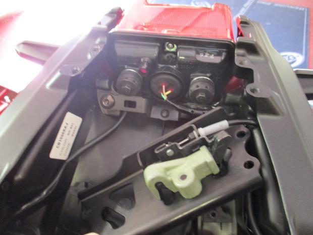
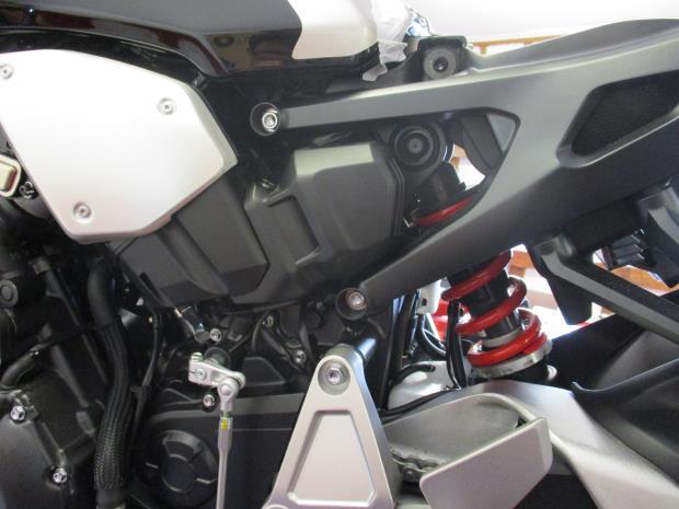
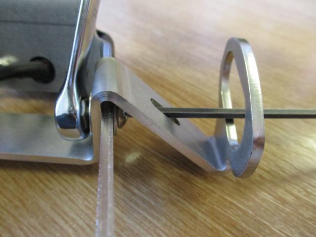
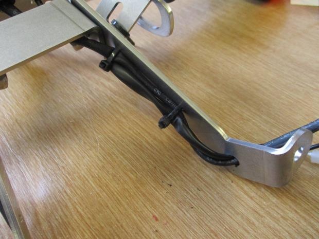
12 Page 12 FITTING INSTRUCTIONS To fit the tail tidy, remove the pillion seat using the motorcycle key as shown in picture 1 and the main seat using the 2 bolts arrowed in picture 2. Remove the 4 bolts from the seat lock bracket shown in picture 3 and place it to the side as shown in picture 4. Unplug the 4 connectors (2 white, 1 orange, 1 blue) shown in picture 5. Unplug the tail light connector shown in picture 6. Remove the 2 bolts shown in pictures 7 and 8 from the light support bracket. Make a note of which colour wires correspond to which side of the bike and remove the indicators. Remove the 2 bolts from the tail light shown in picture 9. The tail light can now be removed from the bike. Locate the air intake cover panel arrowed in picture 10 and remove the bolts from the upper and lower mounts shown in pictures 11 and 12. Unhook the clip from the top of the air intake and pull the air intake away from the airbox as shown in picture 13. Locate the wiring loom tucked behind the airbox shown in picture 14 and unclip the orange and blue connectors. Unclip the 2 wiring clips shown in pictures 15 and 16 by using a small flathead screwdriver to release the cable tie or lever the clip from the slot. Locate the internal support bracket (item 2) as shown in pictures 17, 18 & 19. Fit the indicator mount bracket (item 3) to the licence plate bracket (item 1) as shown in picture 20 using the 2 shorter M5 bolts (item 4), 4 M5 washers (item 11) and 2 M5 nuts (item 9). These bolts are tightened using a spanner on the inside nut and an allen key through the cutout in the indicator bracket as shown in picture 21. Fit the licence plate illuminator (item 15) as shown in picture 22 using the included nuts and bolts. The shroud may require fitting using a small amount of superglue. Protect the wiring using a length of heatshrink (item 21). If using OEM indicators Disassemble both indicator mounting assemblies by removing the bolt and the inner plastic shroud. Remove the metal insert now visible from the back of the indicator. Pull the indicator from the plastic outer of the indicator mounting bracket. Fit the indicators to the correct sides of the indicator bracket by pushing the rubber mounting through the hole, the right side should use the indicator with the blue connector and the left side the orange connector. Slide one of the indicator spacers (item 17) onto the inside of each indicator so that the mounting face of the indicator sits flush against the indicator bracket. Insert the metal insert removed earlier into the back of the indicator in the same way it was removed. Secure the indicators using the 2 longer M5 bolts (item 5). If using mini indicators ( product codes: RG371=LED, RG372=LED Aero) Mount the mini indicators using 2 indicator adaptors (item 16) and 1 indicator spacer (item 17) per side as shown in pictures 23 and 24. The larger face of the outer indicator adaptor fits against the mini indicator with the smaller stepped face sitting inside the indicator bracket. The indicator spacer fits between the inner indicator adaptor and the indicator bracket. Protect the wiring of the mini indicators using a length of heatshrink (item 21) on each indicator. Slide an indicator wiring cover onto each indicator as shown in picture 25. Standard fitting procedure Using one cable tie on each side secure the indicator wire to the bracket as shown in picture 26. Route the indicator and licence plate illuminator wires along the inside of the licence plate bracket, secure using cable ties and pass through the hole as shown in picture 27.
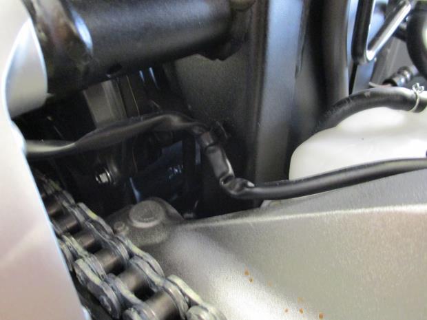
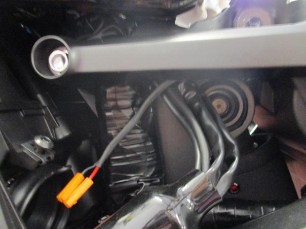
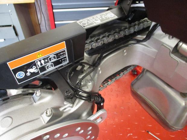
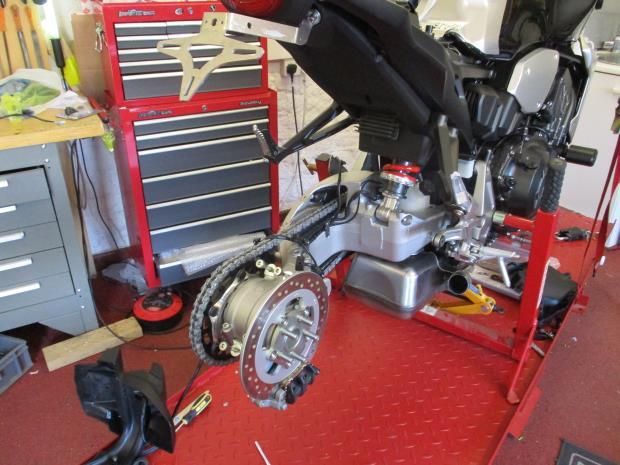
13 Page 13 Place 1 small M6 washer (item 12) onto 1 M6 cap head bolt (item 6) and offer this through the mounting holes on the licence plate bracket (item 1). Place 1 stepped spacer (item 14) onto this bolt with the larger face against the bracket as shown in picture 28. Repeat this for the other side. Offer this assembly up to the exposed indicator mounting holes on the tail of the bike ensuring that the bolts pass through the OEM light mount bracket and the internal support bracket (item 2). Loosely secure the tail bracket using 1 large M6 washer (item 13) and 1 M6 nyloc nut (item 10) per side as shown in picture 17. Replace the seat lock bracket as shown in picture 29 and loosely secure using the M6 hex head bolts (item 7) in the rear 2 holes ensuring that these also pass through the internal support bracket (item 2). Use the original bolts for the front 2 holes. Wind the M6 bolts out until there is just enough thread showing beneath the internal support bracket to fit a small M6 washer (item 12) and M6 nyloc nut (item 10). Hold the M6 nut in position using a spanner while tightening the bolt through from above, this will make it easier to allow the thread to engage fully with the rear subframe of the bike and with the nut simultaneously. Ensure the nut is tight against the internal support bracket and the bolt is tight against the top of the subframe (maximum 15Nm of torque). Tighten the lower internal support bracket and licence plate bracket mounts. Route the wiring through the tail panel holes as shown in picture 30. Connect the licence plate illuminator extension (item 19) to the licence plate illuminator (item 15) connectors. Connect the licence plate illuminator connector (item 18) to the connectors of the extension as shown in picture 31. Route this wiring down the left side of the rear subframe so that it does not interfere with other wiring as shown in picture 32. Push the wiring through the subframe as shown in picture 33 and reconnect the connectors removed in picture 14. If fitting OEM indicators connect the indicator wiring to the wiring connectors in the same way they were removed (picture 5). The right side connectors should be blue & white and the left side orange & white. If fitting mini indicators connect the bullet connectors to the indicator connectors (item 18) and then to the bike connectors (picture 5). The right side connectors should be blue & white and the left side orange & white. Test the indicators and licence plate illuminator for correct function and flash rate, if lights fail to work correctly, swap the connectors. To remove the Honda tail unit without cutting the number plate light wire the rear wheel must be removed. This requires use of a suitable swingarm pivot stand mounted on both sides in the pivot point shown in picture 34. If removing the rear wheel Remove the exhaust silencer be loosening the two clamp bolts in picture 35. Do not completely remove these bolts. Remove the nut and bolt supporting the exhaust (picture 36) from the rear of the footrest while supporting the exhaust. Slide the exhaust away from the bike. Slightly loosen the 5 wheel nuts shown in picture 37. Lift the bike using a swingarm pivot stand. Remove the rear wheel by undoing the 5 wheel nuts. Remove the two bolts holding the wheel mudguard shown in picture 38. Remove the pop rivet holding the chainguard to the mudguard shown in picture 39.
14 Page 14 There is a small L shaped bracket located below the left side mudguard bolt that is likely to fall out when the mudguard is removed, this must be replaced between the mudguard and swingarm in the orientation shown in picture 40. Remove the 2 Philips head screws holding the 2 small brackets shown in picture 41. Remove the cable clip arrowed in picture 42 holding the wire that goes into the tail unit. Check that the number plate light wire is now completely free from all clips and brackets holding it to the swingarm. Remove the 3 bolts holding the tail unit to the swingarm, the location of these bolts when removed is shown in picture 44. Remove the tail unit. Fill the 3 exposed holes with the 3 M8 bolts (item 8). Refit the 2 brackets in picture 41, small L bracket and mudguard (picture 38 & 40), wheel and exhaust in the reverse of the order they were removed. The bike can be lowered from the swingarm pivot stand if convenient. If leaving the rear wheel in place Remove the two bolts holding the wheel mudguard shown in picture 38. Remove the pop rivet holding the chainguard to the mudguard shown in picture 39. There is a small L shaped bracket located below the left side mudguard bolt that is likely to fall out when the mudguard is removed, this must be replaced between the mudguard and swingarm in the orientation shown in picture 40. Cut the number plate light wire shown in picture 45 close to the clip that holds it to the chainguard as indicated by arrows in picture 45. Remove the 3 bolts holding the tail unit to the swingarm, the location of these bolts when removed is shown in picture 44. The upper left side bolt is accessible from the left side of the bike and the other two bolts are accessible through the wheel from the right side. Remove the tail unit. Pull the remaining half the wire through from the connector side (picture 14). Fill the 3 exposed holes with the 3 M8 bolts (item 8). Refit the small L bracket and mudguard (picture 38 & 40). Standard fitting procedure Refit the tail light and reconnect the tail light connector. Refit the air intake and air intake cover panel. Refit the seat as original and licence plate (it may require drilling). Please check the operation of all lights before riding the motorcycle. IMPORTANT: IF FITTING A FULL-SIZE LICENCE PLATE AND PLACING IT FAR DOWN ON THE LICENCE PLATE HANGER, THERE IS A SMALL CHANCE OF THE LICENCE PLATE HITTING THE BACK WHEEL UNDER HEAVY LOAD AND OVER LARGE BUMPS IN THE ROAD. IT IS YOUR RESPONSIBILITY TO CHECK FOR THIS POSSIBILITY AND TAKE AVOIDING ACTION. FAILURE TO CHECK THIS COULD RESULT IN SERIOUS INJURY. Depending on local laws, attach enclosed reflector (item 23) in an appropriate location Retest the license plate illuminator and all lights before riding. ISSUE 1 17/08/2018 (HB) Digital copies of these instructions are available to download from
15 Page 15 CONSUMER NOTICE The catalogue description and any exhibition of samples are only broad indications of the Products and may make design changes which do not diminish their performance or visual appeal and supplying them in such state shall conform to the order. The Buyer acknowledges no representation or warranty (other than as to title) has been given or will apply to the Products other than those in s order or confirmation and the Buyer confirms it has chosen the Products as being of merchantable quality and suitable for its particular purposes. Where fits the Products or undertakes other services it shall exercise reasonable skill and care and rectify any fault free of charge unless the workmanship has been disturbed. The Buyer is responsible for ensuring that the warranty on the motorcycle is not affected by the fitting of the Products. On return of any defective Products shall at its option either supply a replacement or refund the purchase money but shall not be liable if the Products have been modified or used or maintained otherwise than in accordance with s or manufacturer s instructions and good engineering practice or if the defect arises from accident or neglect. Other than identified above and subject to not limiting its liability for causing death and personal injury, it shall not be liable for indirect or consequential loss and otherwise its liability shall be limited to the amounts paid by the Buyer for the Products or the fitting or service concerned. These terms do not affect the Buyer s statutory rights. RETURNS POLICY (NON-FAULTY GOODS) Returns must be pre-authorised (if not pre-authorised the return will be rejected). Goods may only be returned direct to us if they were purchased direct from us (customer must prove if necessary). Otherwise to be returned to original vendor. Goods must be in re-sellable condition, in the opinion of. All returns are subject to a 25% restocking and handling fee (25% of the gross value exc. P&P at the prevailing price at time of purchase). The customer must pay any and all carriage charges. No returns of discontinued products, unless within 14 days of purchase. This policy does not affect your statutory rights and does not refer to faulty goods.
16 NOTICE DE MONTAGE POUR LP0254BK SUPPORT DE PLAQUE HONDA CB1000R 18- Page 16 Le kit contient les articles exposés ci-dessous, vérifier que toutes les pièces soient présentes avant de procéder au montage. La façon dont le kit est emballé ne correspond pas forcément à la façon de monter les pièces sur la moto. LES PARTIES PRESENTEES PEUVENT ETRE UNIQUEMENT REPRESENTATIVES (POUR LA CLARTÉ DES INSTRUCTIONS UNIQUEMENT).
17 Page 17
18 Page 18 LÉGENDE ARTICLE 1 = SUPPORT DE PLAQUE (TB0254 PARTIE 1) (x1). ARTICLE 2 = SUPPORT DE PLAQUE INTERNE (TB0254 PARTIE 2) (x1). ARTICLE 3 = SUPPORT DE FIXATION CLIGNOTANT (TB0254 PARTIE 3) (x1). ARTICLE 4 = M5 x 0.8 x 15mm BOULONS (x2). ARTICLE 5 = M5 x 0.8 x 20mm BOULONS (x2). ARTICLE 6 = M6 x 1.0 x 25mm BOULONS (x2). ARTICLE 7 = M6 x 1.0 x 30mm BOULONS (x2). ARTICLE 8 = M8 x 1.25 x 12mm BOULONS (x3). ARTICLE 9 = M5 ÉCROUS (x2). ARTICLE 10 = M6 ÉCROUS (x4). ARTICLE 11 = 12mm M5 RONDELLES (x4) ARTICLE 12 = 12mm M6 RONDELLES (x4) ARTICLE 13 = 16mm M6 RONDELLES (x2) ARTICLE 14 = 4MM ENTRETOISES (S1136) (x2) ARTICLE 15 = ASSEMBLAGE FEU DE PLAQUE (x1) ARTICLE 16 = ADAPTATEURS DE MINI CLIGNOTANTS(I0034) (x4). ARTICLE 17 = ENTRETOISES DE CLIGNOTANT D ORIGINE (I0032) (x2). ARTICLE 18 = CONNECTEURS DE FEU DE PLAQUE / CLIGNOTANT (CON0059) (x3). ARTICLE 19 = EXTENSIONS DE CONNECTEUR DE FEU DE PLAQUE (CON0044) (x2). ARTICLE 20 = CACHE FILS DE CLIGNOTANT (IWC0002) (x2) ARTICLE 21 = 200MM LONGUEURS DE MANCHON THERMO RÉTRACTABLE (x3). ARTICLE 22 = COLLIERS DE SERRAGE (x6). ARTICLE 23 = RÉFLECTEUR (x1). OUTILS REQUIS Clé métrique 8mm, 10mm. Clés Allen 6mm et 8mm. Clé métrique 13mm. Petit tournevis plat. Tournevis cruciforme. Coupe fil (optionnel, voir instructions) Béquille de pivot du bras oscillant (optionnel, voir instructions) Clé dynamométrique. VALEURS DE SERRAGE M4 BOULON = 8Nm M5 BOULON = 12Nm M6 BOULON = 15Nm M8 BOULON = 20Nm M10 BOULON = 40 Nm
19 Page 19 NOTICE DE MONTAGE Pour monter le support, enlever le siège passager à l aide de la clé de la moto, voir photo 1 et le siège principal à l aide des 2 boulons indiqués sur la photo 2. Enlever les 4 boulons du support de blocage de siège, voir photo 3 puis mettez-les de côté, voir la photo 4. Débrancher les 4 connecteurs (2 blanc, 1 orange, 1 bleu) voir la photo 5. Débrancher le connecteur de feu de plaque, voir la photo 6. Enlever les 2 boulons indiqués sur les photos 7 et 8 du support de fixation de feu. Notez la correspondance des couleurs de fils, ainsi que le côté de la moto d où ils sont issus, puis enlever les clignotants. Enlever les 2 boulons du support de feu, voir la photo 9. Le support de feu peut maintenant être enlevé de la moto. Placer le panneau cachant la prise d'air, voir la photo 10 puis enlever les boulons des supports supérieurs et inférieurs, voir les photos 11 et 12. Décrochez le clip du haut de la prise d aire puis tirer la prise d aitre de la boîte à air, voir photo 13. Placer le faisceau de câbles cache derrière la boîte à air, voir photo 14 puis déclipser les connecteurs orange et bleu. Déclipser les 2 clips de fils, voir les photos 15 et 16 en utilisant un petit tournevis plat pour libérer le collier de serrage ou lever le clip de la fente. Placer le support interne (article 2) voir les photos 17, 18 & 19. Monter le support de fixation du clignotant (article 3) sur le support de plaque (article 1), voir la photo 20, en utilisant les 2 boulons M5 (article 4), 4 rondelles M5 (article 11) et 2 écrous M5 (article 9). Serrer ces boulons en utilisant une clé à molette à l intérieur de l écrou et une clé Allen dans l ouverture du support de clignotant, voir la photo 21. Monter le feu de plaque (article 15), voir la photo 22 en utilisant les écrous et boulons inclus. Vous pourriez avoir besoin d un peu de glue pour coller le linceul. Protéger le fil à l aide de la protection thermos rétractable (article 21). Si vous utilisez les clignotants d origine Désassembler les 2 ensembles de fixation clignotants en enlevant le boulon et le linceul plastique interne. Enlever l insert métallique visible à l arrière du clignotant. Tirez le clignotant de l'extérieur en plastique de son support de montage. Monter les clignotants des bons côtés du support de clignotant en poussant le support en caoutchouc dans le trou. On devrait avoir le clignotant au connecteur bleu du côté droit, et le clignotant au connecteur orange du côté gauche. Glisser une des entretoises de clignotant (article 17) à l intérieur de chaque clignotant de façon à ce que la face de fixation du clignotant se place à fleur du support de clignotant. Insérer l insert métallique enlevé un peu plus tôt à l arrière du clignotant de la même façon qu il a été enlevé. Fixer les clignotants en utilisant les 2 boulons M5 (article 5). Si vous utilisez des mini clignotants (code produit : RG371=LED, RG372=LED latérale) Monter les mini clignotants à l aide des 2 adaptateurs de clignotant (article 16) et d une entretoise de clignotant (article 17) de chaque côté, voir les photos 23 et 24. La face plus large de l adaptateur extérieur de clignotant se place contre le mini clignotant avec la face crantée placée à l intérieur du support de clignotant. L entretoise de clignotant se place entre l adaptateur de clignotant interne et le support de clignotant. Protéger le fil des mini clignotants en utilisant une longueur de manchon thermo rétractable (article 21) sur chaque clignotant. Glisser un cache fil de clignotant sur chaque clignotant, voir la photo 25.
20 Page 20 Procédure d installation standard Utliser un serre-câble de chaque côté pour fixer le fil de clignotant sur le support, voir photo 26. Router les fils de clignotant et ceux du feu de plaque à l intérieur du support de plaque, fixer à l aide des serrecâbles puis passez les dans le trou, voir photo 27. Placer 1 petite rondelle M6 (article 12) sur le boulon M6 (article 6) puis insérez le dans les trous de fixation du support de plaque plate (article 1). Placer 1 entretoise crantée (article 14) sur le boulon avec la face plus large contre le support, voir photo 28. Répéter cette opération de l autre côté. Monter l ensemble sur les trous de fixation du clignotant sur la queue de la moto en veillant à ce que les boulons passent dans le support de montage de feu d origine et le support de fixation interne (article 2). Serrer légèrement le support de queue en utilisant 1 rondelle large M6 (article 13) et 1 écrou M6 (article 10) par côté, voir photo 17. Replacer le support de fixation du siège, voir photo 29 puis serrer légèrement en utilisant les boulons M6 (article 7) dans les 2 trous arrière en veillant à ce qu ils passent dans le support de fixation interne 2 (article 2). Utiliser les boulons d origine pour les 2 trous. Enroulez les boulons M6 jusqu à ce qu il y ait juste assez de fil sous le support interne pour insérer une petite rondelle M6 (article 12) et un écrou M6 (article 10). Maintenez l'écrou M6 en place à l'aide d'une clé tout en serrant le boulon par le haut. Cela facilitera l'engagement du fil dans le sous-cadre arrière de la moto et avec l'écrou simultanément. Assurez-vous que l'écrou soit serré contre le support interne et que le boulon soit serré contre le haut du sous-cadre (15 Nm de couple maximum). Serrer le support de fixation inférieur interne et les supports de plaque. Router le fil dans les trous de panneaux de la queue, voir photo 30. Connecter l extension de feu de plaque (article 19) sur les connecteurs de feu de plaque (article 15). Connecter le connecteur de feu de plaque (article 18) sur les connecteurs de l extension, voir photo 31. Router le fil du côté gauche du sous-cadre arrière afin qu il n interfère pas avec un autre câblage, voir la photo 32. Poussez le fil de feu de plaque dans le sous-cadre, voir la photo 33, et rebranchez les connecteurs enlevés sur la photo 14. Si des clignotants d origine sont installés, connectez le fil de clignotant aux connecteurs de fils de la même manière qu'ils ont été enlevés (photo 5). Les connecteurs du côté droit doivent être bleu et blanc et orange et blanc du côté gauche. Si vous montez les mini clignotants, connectez les connecteurs sur les connecteurs de clignotant (article 18) puis sur les connecteurs de la moto (photo 5). Les connecteurs du côté droit doivent être bleu & blanc et orange & blanc du côté gauche. Tester les clignotants et le feu de plaque pour vérifier leur fonctionnement et niveau d éclairage, si l éclairage échoue, tournez les connecteurs. Pour enlever l unité de queue de support Honda sans couper le fil de feu de plaque, la roue arrière doit être enlevée. Cela nécessite d utiliser une béquille de pivot du bras oscillant de chaque côté du point de pivot du bras oscillant, voir la photo 34. Si vous retirez la roue arrière Enlever le silencieux d échappement en desserrant les 2 boulons de fixation, voir la photo 35. Ne pas enlever complètement ces boulons. Enlever l écrou et le boulons qui fixent l échappement (photo 36) à l arrière du repose pied, tout en supportant l échappement. Retirez l échappement de la moto. Desserrer les 5 écrous de roue, voir la photo 37.
21 Page 21 Lever la moto à l aide d une béquille de pivot du bras oscillant. Enlever la roue arrière en enlevant les 5 écrous de roue. Enlever les 2 boulons qui fixent le garde-boue, voir photo 38. Enlever le rivet qui fixe le protège-chaîne sur le garde-boue, voir la photo 39. Il y a un petit support en L place sous le boulon de garde-boue du côté gauche qui pourrait tomber lors du démontage du garde-boue. Il doit être replace entre le garde-boue et le bras oscillant selon l orientation indiquée sur la photo 40. Enlever les 2 vis cruciformes fixant les 2 petits supports, voir la photo 41. Enlever le clip câble, indiqué sur la photo 42, qui fixe le fil qui va se place dans l unité de queue. Vérifier que le fil de feu de plaque est maintenant libre des tous ses clips et supports qui le fixent sur le bras oscillant. Enlever les 3 boulons qui fixent l unité de queue au bras oscillant, la position des boulons enlevés est présentée sur la photo 44. Enlever l unité de queue. Boucher les 3 trous avec 3 boulons M8 (article 8). Remonter les 2 supports visibles sur la photo 41, un petit support L et le garde-boue (photo 38 & 40), la roue et l échappement en procédant à l inverse de la façon dont ces éléments ont été enlevés. La moto peut être abaissée de sa béquille de pivot de bras oscillant. Si vous laissez la roue arrière Enlever les 2 boulons qui fixent le garde-boue, voir la photo 38. Enlever le rivet qui fixe le protège chaine sur le garde-boue, voir photo 39. Il y a un petit support L placé sous le boulon de garde-boue du côté gauche qui pourrait tomber lors du démontage du garde-boue. Il doit être replace entre le garde-boue et le bras oscillant selon l orientation indiquée sur la photo 40. Couper le fil de feu de plaque, voir photo 45 proche du clip qui le fixe au protège chaine, voir la photo 45. Enlever les 3 boulons qui fixent l unité de queue au bras oscillant, la position de ces boulons enlevés est visible sur la photo 44. Le boulon supérieur du côté gauche est accessible du côté gauche de la moto et les 2 autres boulons sont accessibles à travers la roue du côté droit. Enlever l unité de queue. Tirer la moitié restante du fil à travers son côté connecteur. (Photo 14). Boucher les 3 trous avec 3 boulons M8 (article 8). Remonter le petit support L et le garde-boue (photo 38 & 40). Procédure de montage standard Remonter le feu de queue de support puis reconnecter le connecteur. Remonter la prise d admission d air le cache de la prise d admission d air. Remonter le siège comme à l origine et le feu de plaque (peut nécessiter un perçage). Vérifier que l ensemble des feux fonctionne avant de prendre la route. IMPORTANT : Si vous installez une grosse plaque, il y a un risque que la plaque entre en contact avec la roue arrière en cas de choc sur la route (bosse, grosse charge etc..). Il est de votre responsabilité de vérifier que cela ne puisse pas se produire. Ne pas effectuer ces vérifications peut entrainer des dommages ainsi que des blessures graves pour le pilote. Selon les lois locales, attacher le réflecteur rouge (article 23) à l endroit approprié. Tester le feu de plaque, les clignotants, ainsi que l ensemble des feux avant de prendre la route. ISSUE 1 17/08/2018 (HB)
22 Notice disponible au téléchargement sur Page 22 CONSUMER NOTICE The catalogue description and any exhibition of samples are only broad indications of the Products and may make design changes which do not diminish their performance or visual appeal and supplying them in such state shall conform to the order. The Buyer acknowledges no representation or warranty (other than as to title) has been given or will apply to the Products other than those in s order or confirmation and the Buyer confirms it has chosen the Products as being of merchantable quality and suitable for its particular purposes. Where fits the Products or undertakes other services it shall exercise reasonable skill and care and rectify any fault free of charge unless the workmanship has been disturbed. The Buyer is responsible for ensuring that the warranty on the motorcycle is not affected by the fitting of the Products. On return of any defective Products shall at its option either supply a replacement or refund the purchase money but shall not be liable if the Products have been modified or used or maintained otherwise than in accordance with s or manufacturer s instructions and good engineering practice or if the defect arises from accident or neglect. Other than identified above and subject to not limiting its liability for causing death and personal injury, it shall not be liable for indirect or consequential loss and otherwise its liability shall be limited to the amounts paid by the Buyer for the Products or the fitting or service concerned. These terms do not affect the Buyer s statutory rights. RETURNS POLICY (NON-FAULTY GOODS) Returns must be pre-authorised (if not pre-authorised the return will be rejected). Goods may only be returned direct to us if they were purchased direct from us (customer must prove if necessary). Otherwise to be returned to original vendor. Goods must be in re-sellable condition, in the opinion of. All returns are subject to a 25% restocking and handling fee (25% of the gross value exc. P&P at the prevailing price at time of purchase). The customer must pay any and all carriage charges. No returns of discontinued products, unless within 14 days of purchase. This policy does not affect your statutory rights and does not refer to faulty goods.
23 MONTAGEANLEITUNG FÜR LP0254BK KENNZEICHENHALTER HONDA CB1000R 18- Page 23 ALLE TEILE SIND UNTEN ABGEBILDET UND GEKENNZEICHNET. BEVOR SIE MIT DER MONTAGE BEGINNEN, ÜBERPRÜFEN SIE, DASS ALLE TEILE VORHANDEN SIND. Hinweis: Die Verpackung der Teile stellt nicht die Reihenfolge der Montage dar. DIE UNTEN ABGEBILDETEN TEILE DIENEN LEDIGLICH ZUR ERKLÄRUNG
24 Page 24
25 Page 25 LIEFERUMFANG ARTIKEL 1 = KENNZEICHENHALTER (TB0254 TEIL 1) (x1). ARTIKEL 2 = INTERNE BEFESTIGUNGSBÜGEL (TB0254 TEIL 2) (x1) ARTIKEL 3 =MONTAGEHALTERUNG FÜR DIE BLINKER (TB0254 TEIL 3) (x1) ARTIKEL 4 = M5 x 0,8 x 15mm INBUSSCHRAUBE (x2) ARTIKEL 5 = M5 x 0,8 x 20mm SECHSKANTSCHRAUBE (x2) ARTIKEL 6 = M6 x 1,0 x 25mm INBUSSCHRAUBE (x2) ARTIKEL 7 = M6 x 1,0 x 30mm SECHSKANTSCHRAUBE (x2) ARTIKEL 8 = M8 x 1,25 x 12mm INBUSSCHRAUBE (x3) ARTIKEL 9 = M5 SELBSTSICHERNDE MUTTER (x2) ARTIKEL 10 = M6 SELBSTSICHERNDE MUTTER (x4) ARTIKEL 11 = 12mm M5 UNTERLEGSCHEIBE (x4) ARTIKEL 12 = 12mm M6 UNTERLEGSCHEIBE (x4) ARTIKEL 13 = 16mm M6 UNTERLEGSCHEIBE (x2) ARTIKEL 14 = 4mm DISTANZHALTER GESTUFT (S1136) (x2) ARTIKEL 15 = KENNZEICHENBELEUCHTUNG (x1) ARTIKEL 16 = ADAPTER FÜR MINIBLINKER (I0034) (x4) ARTIKEL 17 = ORIGINAL DISTANZHALTER FÜR BLINKER (I0032) (x2) ARTIKEL 18 = KABELVERBINDER FÜR BLINKER/KENNZEICHENBELEUCHTUNG (CON0059) (x3) ARTIKEL 19 = VERLÄNGERUNG KABELVERBINDER FÜR KENNZEICHENBELEUCHTUNG (CON0044) (x2) ARTIKEL 20 = KABELABDECKUNGEN FÜR BLINKER (IWC0002) (x2) ARTIKEL 21 = 200MM SCHRUMPFSCHLAUCH (x3) ARTIKEL 22 = KLEINE KABELBINDER (x6) ARTIKEL 23 = RÜCKSTRAHLER (x1) SIE BENÖTIGEN FOLGENDES WERKZEUG: Satz Steckschlüssel mit 8mm und 10mm Steckschlüssel Satz Inbusschlüssel mit 6mm und 8mm Inbusschlüssel Schraubenschlüssel (13mm) Kleinen, flachen Schraubendreher Kreuzschlitzschraubendreher Seitenscheider (optional - siehe Montageanleitung) Rennsport-Montageständer (optional - siehe Montageanleitung) Drehmomentschlüssel MAX. ANZUGSDREHMOMENT: M4 Schraube = 8 Nm M5 Schraube = 12 Nm M6 Schraube = 15 Nm M8 Schraube = 20 Nm M10 Schraube = 40Nm
26 Page 26 MONTAGEANLEITUNG Um den Kennzeichenhalter montieren zu können, entfernen Sie zuerst den Beifahrersitz (der Schlüssel wird hierfür benötigt) wie in Abbildung 1 abgebildet, und den Fahrersitz die Schrauben sind in Abbildung 2 gekennzeichnet. Entfernen Sie die 4 Schrauben von der Halterung für die Sitzverriegelung, die in Abbildung 3 markiert sind, und legen Sie sie zur Seite siehe Abbildung 4. Trennen Sie die vier Steckverbinder (2 weiß, 1 orange, 1 blau), die in Abbildung 5 gekennzeichnet sind. Trennen Sie den Steckverbinder für die Kennzeichenbeleuchtung siehe Abbildung 6. Entfernen Sie die 2 Schrauben, die in den Abbildungen 7 und 8 abgebildet sind vom Befestigungsbügel für das Licht. Notieren Sie die Verlegung der Kabel (rechte/linke Seite des Motorrades), bevor Sie die Blinker entfernen. Entfernen Sie die zwei Schrauben von der Kennzeichenbeleuchtung, die in Abbildung 9 abgebildet sind. Das Rücklicht kann nun vom Motorrad entfernt werden. Die Abdeckung für den Lufteinlass, die in Abbildung 10 gekennzeichnet ist lokalisieren und die Schrauben von den oberen und unteren Halterungen entfernen siehe Abbildungen 11 und 12. Den Clip oben auf dem Lufteinlass aushaken und den Lufteinlass von der Airbox entfernen, wie in Abbildung 13 abgebildet. Den Kabelstrang hinter der Airbox lokalisieren (siehe Abbildung 14) und den orangen sowie den blauen Steckverbinder trennen. Lösen Sie die zwei Clips an den Kabeln, die in den Abbildungen 15 und 16 abgebildet sind benutzen Sie einen kleinen flachen Schraubenzieher, um den Kabelbinder zu lösen oder den Clip aus der Spalte zu heben. Den inneren Stützbügel (Artikel 2) fixieren wie in den Abbildungen 17, 18 & 19 abgebildet. Montieren Sie die Montagehalterung für die Blinker (Artikel 3) am Kennzeichenhalter (Artikel 1) wie in Abbildung 20 abgebildet und mit den zwei kürzeren M5 Schrauben (Artikel 4), 4 x M5 Unterlegscheiben (Artikel 11) und 2 x M5 Muttern (Artikel 9) befestigen. Die Schrauben werden angezogen mit einem kleinen Schraubenschlüssel an der inneren Mutter und einem Inbusschlüssel durch den Ausschnitt in der Blinkerhalterung wie in Abbildung 21 abgebildet. Montieren Sie die Kennzeichenbeleuchtung (Artikel 15) wie in Abbildung 22 abgebildet mit den mitgelieferten Muttern und Schrauben. Etwas Sekundenkleber benutzen, um die Abdeckung für die Kennzeichenbeleuchtung in Position zu halten. Eine Länge Schrumpfschlauch (Artikel 21) an den Kabeln anbringen, um sie zu schützen. Wenn Sie die original Blinker montieren Beide Blinker-Montageeinheiten zerlegen, indem Sie die Schraube und die innere Plastikabdeckung entfernen. Entfernen Sie den Metalleinsatz, der nun zu sehen ist von hinten am Blinker. Den Blinker aus dem Plastik an der Blinker-Montagehalterung rausziehen. Montieren Sie die Blinker an der jeweils entsprechenden Seite der Blinkerhalterung, indem Sie die Kunststoff- Befestigung durch die Öffnung schieben an der rechten Seite sollte der blaue Steckverbinder sein und an der linken Seite der orange Steckverbinder. Einen der Distanzhalter für die Blinker (Artikel 17) an der Innenseite des Blinkers anbringen, sodass die Montagefläche des Blinkers eng an der Blinkerhalterung anliegt. Den zuvor entfernten Metalleinsatz hinten am Blinker wieder anbringen. Die Blinker mit den 2 längeren M5 Schrauben (Artikel 5) befestigen. Wenn Sie Mini-Blinker montieren ( Artikel-Nr. RG371=LED, RG372=LED Aero) Die Miniblinker montieren Sie wie folgt: Je 2 x Adapter (Artikel 16) und 1 Distanzhalter (Artikel 17) an beiden Seiten anbringen wie in den Abbildungen 23 und 24 abgebildet. Die größere Fläche des äußeren Adapters am Miniblinker anliegend und die kleinere gestufte Fläche innerhalb der Blinker-Halterung. Der Distanzhalter liegt zwischen dem inneren Adapter und der Blinkerhalterung.
27 Jeweils eine Länge des mitgelieferten Schrumpfschlauchs (Artikel 21) an beiden Kabeln für die Miniblinker anbringen. Die Kabelabdeckungen an beiden Blinkern anbringen siehe Abbildung 25. Page 27 Standard Montage Benutzen Sie jeweils einen Kabelbinder an beiden Seiten, um die Blinkerkabel an der Halterung zu befestigen - siehe Abbildung 26. Die Kabel für die Blinker und die Kennzeichenbeleuchtung an der Innenseite des Kennzeichenhalters verlegen und mit Kabelbindern befestigen und durch die Öffnung führen siehe Abbildung 27. Eine kleine M6 Unterlegscheibe (Artikel 12) an einer M6 Inbusschraube (Artikel 6) anbringen, und diese in die Montageöffnungen am Kennzeichenhalter (Artikel 1) einführen. Einen gestuften Distanzhalter (Artikel 14) an die Schraube anbringen mit der größeren Fläche an der Halterung anliegend siehe Abbildung 28. Diesen Schritt an der anderen Seite wiederholen. Die Einheit an den offenen Montageöffnungen für die Blinker am Kennzeichenhalter anbringen bitte darauf achten, dass die Schrauben durch die original Montagehalterung für die Beleuchtung in den inneren Befestigungsbügel (Artikel 2) eingedreht werden. Den Kennzeichenhalter mit einer großen M6 Unterlegscheibe (Artikel 13) und einer M6 selbstsichernden Mutter (Artikel 10) an jeder Seite lose befestigen siehe Abbildung 17. Die Halterung für die Sitzverriegelung wieder anbringen siehe Abbildung 29 - und mit den M6 Sechskantschrauben (Artikel 7) in den hinteren 2 Öffnungen lose befestigen. Bitte darauf achten, dass die Schrauben auch in den inneren Befestigungsbügel (Artikel 2) eingeführt werden. Die original Schrauben werden für die vorderen 2 Öffnungen verwendet. Die M6 Schrauben ausdrehen bis ausreichend Gewinde unterhalb des internen Befestigungsbügels vorhanden ist, um eine kleine M6 Unterlegscheibe (Artikel 12) und M6 selbstsichernde Mutter (Artikel 10) anbringen zu können. Halten Sie die M6 Mutter in Position mit einem Schraubenschlüssel während Sie die Schraube von oben anziehen. Somit kann das Gewinde einfacher bzw. gleichzeitig mit dem hinteren Hilfsrahmen des Motorrades und mit der Mutter einrasten. Bitte darauf achten, dass die Mutter eng am internen Befestigungsbügel anliegt und die Schraube oben eng am Hilfsrahmen sitzt (max. 15Nm Anzugsdrehmoment). Den unteren internen Befestigungsbügel und die Halterungen für den Kennzeichenhalter befestigen. Die Kabel durch die Öffnungen am Heck verlegen siehe Abbildung 30. Verbinden Sie die Verlängerung für den Kabelverbinder (für die Kennzeichenbeleuchtung - Artikel 19) mit den Verbindungen für die Kennzeichenbeleuchtung (Artikel 15). Verbinden Sie den Kabelverbinder für die Kennzeichenbeleuchtung (Artikel 18) mit den Kabelverbindern für die Verlängerung siehe Abbildung 31. Diese Kabel an der linken Seite des hinteren Hilfsrahmens verlegen, sodass sie die andere Verkabelung nicht überlagern siehe Abbildung 32. Die Kabel für die Kennzeichenbeleuchtung durch den Hilfsrahmen führen (siehe Abbildung 33) und die Kabelverbinder, die zuvor getrennt wurden, wieder verbinden - siehe Abbildung 14. Wenn Sie die original Blinker montieren, verbinden Sie die Kabel für die Blinker mit den Kabelverbindern wie ursprünglich wieder (Abbildung 5). Die Verbinder an der rechten Seite sind blau & weiß, und an der linken Seite orange & weiß. Wenn Sie Miniblinker montieren, verbinden Sie die Verbindungen mit den Kabelverbindern für die Blinker (Artikel 18), dann mit den Verbindungen vom Motorrad (Abbildung 5). Die Verbinder an der rechten Seite sind blau & weiß, und an der linken Seite orange & weiß. Überprüfen Sie nun die Funktion der kompletten Beleuchtung und sowie die Blinkgeschwindigkeit der Blinker. Falls die Beleuchtung nicht funktionieren sollte, tauschen Sie die Kabel untereinander.
28 Wenn Sie den Honda Kennzeichenhalter entfernen wollen, ohne das Kabel für die Kennzeichenbeleuchtung schneiden zu müssen, muss das Hinterrad abmontiert werden. Hierfür wird ein Rennsport-Montageständer benötigt, so dass das Motorrad an beiden Seiten am Schwerpunkt gestützt ist siehe Abbildung 34. Page 28 Wenn Sie das Hinterrad abmontieren Entfernen Sie den Schalldämpfer, indem Sie die zwei Klemmschrauben lösen siehe Abbildung 35. Diese Schrauben nicht komplett entfernen. Entfernen Sie die Mutter und die Schraube, die den Auspuff fixieren (Abbildung 36) von hinten an der Fußraste stützen Sie dabei den Auspuff. Den Auspuff vom Motorrad entfernen. Die 5 Radmuttern etwas lockern siehe Abbildung 37. Das Motorrad mit einem Rennsport-Montageständer aufbocken. Entfernen Sie das Hinterrad indem Sie die 5 Radmuttern lösen. Entfernen Sie die zwei Schrauben, die den Kotflügel befestigen siehe Abbildung 38. Entfernen Sie die Niete, die den Kettenschutz am Kotflügel befestigt siehe Abbildung 39. Die L-geformte Halterung unter der linken Schraube für den Kotflügel wird wahrscheinlich rausfallen, wenn der Kotflügel entfernt wird. Diese Halterung muss wieder zwischen dem Kotflügel und der Schwinge montiert werden siehe Abbildung 40. Entfernen Sie die zwei Kreuzschlitzschrauben, die die zwei kleinen Halterungen befestigen siehe Abbildung 41. Entfernen Sie den Kabelclip, der in Abbildung 42 gekennzeichnet ist das Kabel, das in den Kennzeichenhalter rein geht hierbei halten. Überprüfen Sie, dass das Kabel für die Kennzeichenbeleuchtung jetzt von allen Clips und Halterungen frei ist, die das Kabel an der Schwinge fixierten. Entfernen Sie die 3 Schrauben, die den Kennzeichenhalter an der Schwinge befestigen die Positionen der Schrauben nach der Entfernung sehen Sie in Abbildung 44. Entfernen Sie den Kennzeichenhalter. Die drei M8 Schrauben (Artikel 8) in die 3 Öffnungen einführen. Montieren Sie die 2 Halterungen in Abbildung 41, die kleine L-Halterung und den Kotflügel (Abbildung 38 & 40), das Rad und den Auspuff in umgekehrter Reihenfolge der vorherigen Entfernung wieder. Sie können das Motorrad nun vom Montageständer runternehmen. Wenn Sie das Hinterrad nicht abbauen Entfernen Sie die zwei Schrauben, die den Kotflügel befestigen siehe Abbildung 38. Entfernen Sie die Niete, die den Kettenschutz am Kotflügel befestigt siehe Abbildung 39. Die L-geformte Halterung unter der linken Schraube für den Kotflügel wird wahrscheinlich rausfallen, wenn der Kotflügel entfernt wird. Diese Halterung muss wieder zwischen dem Kotflügel und der Schwinge montiert werden siehe Abbildung 40. Das Kabel für die Kennzeichenbeleuchtung schneiden wie in Abbildung 45 abgebildet der Clip, der das Kabel am Kettenschutz hält, schließen - siehe Abbildung 45. Entfernen Sie die 3 Schrauben, die den Kennzeichenhalter an der Schwinge befestigen die Positionen der Schrauben nach der Entfernung sehen Sie in Abbildung 44. Die obere linke Schraube ist von der linken Seite des Motorrades zugänglich, die anderen zwei Schrauben sind durch das Rad von der rechten Seite zu erreichen. Entfernen Sie den Kennzeichenhalter. Die übrige Hälfte des Kabels von der Seite mit dem Verbinder durchziehen (Abbildung 14). Die drei M8 Schrauben (Artikel 8) in die 3 Öffnungen einführen. Die kleine L-Halterung und den Kotflügel wieder montieren (Abbildung 38 & 40).
29 Page 29 Standard Montage Montieren Sie das Rücklicht wieder und verbinden Sie den Steckverbinder für das Licht. Montieren Sie den Lufteinlass und die Abdeckung wie ursprünglich wieder. Montieren Sie den Sitz wie ursprünglich wieder und das amtliche Kennzeichen (Bohrungen im Kennzeichen sind evtl. notwendig). WICHTIG: WENN EIN GROSSES KENNZEICHEN ZU WEIT NACH UNTEN MONTIERT WIRD, BESTEHT BEI SCHWERER LAST ODER DURCH GROSSE BODENWELLEN EIN GERINGES RISIKO, DASS DAS KENNZEICHEN AN DAS HINTERRAD STOSSEN KANN. ES LIEGT IN IHRER VERANTWORTUNG DIES ZU ÜBERPRÜFEN UND, WENN NOTWENDIG, ZU VORBEUGENDEN MASSNAHMEN ZU ERGREIFEN. DIE NICHTBEACHTUNG DIESES SICHERHEITSHINWEISES KANN ZU SCHWEREN VERLETZUNGEN FÜHREN. Entsprechend der gesetzlichen Vorschriften, den mitgelieferten Rückstrahler (Artikel 23) anbringen. Überprüfen Sie die Funktion der kompletten Beleuchtung (Blinker und Kennzeichenhalter-Beleuchtung) vor Gebrauch des Fahrzeuges. AUSGABE 1 17/08/2018 (HB) Eine digitale Version dieser Montageanleitung kann auf folgender Seite heruntergeladen werden: CONSUMER NOTICE The catalogue description and any exhibition of samples are only broad indications of the Products and may make design changes which do not diminish their performance or visual appeal and supplying them in such state shall conform to the order. The Buyer acknowledges no representation or warranty (other than as to title) has been given or will apply to the Products other than those in s order or confirmation and the Buyer confirms it has chosen the Products as being of merchantable quality and suitable for its particular purposes. Where fits the Products or undertakes other services it shall exercise reasonable skill and care and rectify any fault free of charge unless the workmanship has been disturbed. The Buyer is responsible for ensuring that the warranty on the motorcycle is not affected by the fitting of the Products. On return of any defective Products shall at its option either supply a replacement or refund the purchase money but shall not be liable if the Products have been modified or used or maintained otherwise than in accordance with s or manufacturer s instructions and good engineering practice or if the defect arises from accident or neglect. Other than identified above and subject to not limiting its liability for causing death and personal injury, it shall not be liable for indirect or consequential loss and otherwise its liability shall be limited to the amounts paid by the Buyer for the Products or the fitting or service concerned. These terms do not affect the Buyer s statutory rights. RETURNS POLICY (NON-FAULTY GOODS) Returns must be pre-authorised (if not pre-authorised the return will be rejected). Goods may only be returned direct to us if they were purchased direct from us (customer must prove if necessary). Otherwise to be returned to original vendor. Goods must be in re-sellable condition, in the opinion of. All returns are subject to a 25% restocking and handling fee (25% of the gross value exc. P&P at the prevailing price at time of purchase). The customer must pay any and all carriage charges. No returns of discontinued products, unless within 14 days of purchase. This policy does not affect your statutory rights and does not refer to faulty goods.
Fitting Instructions for DG0017 BK Downpipe Grille BMW F800GT 2013
 Fitting Instructions for DG0017 BK Downpipe Grille BMW F800GT 2013 In This Kit There Should Be 1 x Downpipe Grille (DG0017) 2 x M5 Nyloc nuts PICTURE 1 PICTURE 2 PICTURE 3 PICTURE 4 1 PICTURE 5 PICTURE
Fitting Instructions for RAD0185BK Radiator Guard TRIUMPH STREET TRIPLE RX 2015
 Fitting Instructions for RAD0185BK Radiator Guard TRIUMPH STREET TRIPLE RX 2015 In This Kit There Should Be 1x Radiator Guard (RAD0185BK) 4x 100mm Lengths of self-adhesive Foam Picture 1 Picture 2 Picture
Fitting Instructions for RAD0129BK Radiator Guard MV AGUSTA F3 2012
 Fitting Instructions for RAD0129BK Radiator Guard MV AGUSTA F3 2012 In This Kit There Should Be 1x Radiator Guard (RAD0129BK) 2x 100mm Lengths of self-adhesive Foam 1x Cable Tie Picture 1 Picture 2 Picture
Fitting Instructions for SRG0013 Radiator Guard KAWASAKI ER6-N / ER6-F / 650 Versys 10-
 Fitting Instructions for SRG0013 Radiator Guard KAWASAKI ER6-N 09-11 / ER6-F 09-11 / 650 Versys 10- PICTURE 1 PICTURE 2 In This Kit There Should Be 1x Radiator Guard 1x M6x20mm long button head bolt 1x
Fitting Instructions for DG0011 BK Downpipe Grille TRIUMPH TROPHY 2012
 Fitting Instructions for DG0011 BK Downpipe Grille TRIUMPH TROPHY 2012 In This Kit There Should Be 1x Downpipe Grille (DG0011) Picture 1 Picture 2 1 FITTING INSTRUCTIONS Picture 3 Picture 4 TOOLS REQUIRED
FITTING INSTRUCTIONS FOR LP0248BK LICENCE PLATE BRACKET KTM DUKE
 FITTING INSTRUCTIONS FOR LP0248BK LICENCE PLATE BRACKET KTM DUKE 790 18- Page 1 THIS KIT CONTAINS THE ITEMS PICTURED AND LABELLED BELOW. DO NOT PROCEED UNTIL YOU ARE SURE ALL PARTS ARE PRESENT. Please
Fitting Instructions for DG0012 BK Downpipe Grille KAWASAKI NINJA
 Fitting Instructions for DG0012 BK Downpipe Grille KAWASAKI NINJA 300 2013-- In This Kit There Should Be 1x Downpipe Grille (DG0012) 2x M6 x 30mm Button Head Bolts 2 3 4 1 5 6 Picture 1 Picture 2 1 Picture
Fitting Instructions for RAD0151BK Radiator Guard BMW R1200GS 2013
 Fitting Instructions for RAD0151BK Radiator Guard BMW R1200GS 2013 In This Kit There Should Be 2x Radiator Guard (RAD0151BK Left & Right) 2x 100mm Lengths of self-adhesive Foam Picture 1 Picture 2 Picture
FITTING INSTRUCTIONS FOR LP0104BK LICENCE PLATE BRACKET HONDA CBR 250R 2011/ WK SP250 / 125 / 50
 FITTING INSTRUCTIONS FOR LP0104BK LICENCE PLATE BRACKET HONDA CBR 250R 2011/ WK SP250 / 125 / 50 Page 1 THIS KIT CONTAINS THE ITEMS PICTURED AND LABELLED BELOW. DO NOT PROCEED UNTIL YOU ARE SURE ALL PARTS
FITTING INSTRUCTIONS FOR SBP0005 SPINDLE BLANKING PLATES DUCATI DIAVEL, MONSTER & PANIGALE MULTISTRADA 1200
 FITTING INSTRUCTIONS FOR SBP0005 SPINDLE BLANKING PLATES DUCATI DIAVEL, MONSTER1200 14- & PANIGALE 1199 2011- MULTISTRADA 1200 THIS KIT CONTAINS THE ITEMS PICTURED AND LABELLED BELOW. DO NOT PROCEED UNTIL
FITTING INSTRUCTIONS FOR AB0013BK ADVENTURE BARS APRILIA CAPONORD
 FITTING INSTRUCTIONS FOR AB001BK ADVENTURE BARS APRILIA CAPONORD 1200 201-1 PICTURE A PICTURE B THIS KIT CONTAINS THE ITEMS PICTURED AND LABELLED BELOW. DO NOT PROCEED UNTIL YOU ARE SURE ALL PARTS ARE
FITTING INSTRUCTIONS FOR LP0245BK LICENCE PLATE BRACKET KAWASAKI NINJA (FOR USE WITH STANDARD AND R&G MINI INDICATORS (8mm))
)") FITTING INSTRUCTIONS FOR LP0245BK LICENCE PLATE BRACKET KAWASAKI NINJA 400 2018 (FOR USE WITH STANDARD AND R&G MINI INDICATORS (8mm)) Page 1 THIS KIT CONTAINS THE ITEMS PICTURED AND LABELLED BELOW. DO
FITTING INSTRUCTIONS FOR LP0245BK LICENCE PLATE BRACKET KAWASAKI NINJA 400 2018 (FOR USE WITH STANDARD AND R&G MINI INDICATORS (8mm)) Page 1 THIS KIT CONTAINS THE ITEMS PICTURED AND LABELLED BELOW. DO
FITTING INSTRUCTIONS FOR CP0273 FRONT MOUNTING CRASH PROTECTORS TRIUMPH SPEED TRIPLE 2011 PICTURE 1 PICTURE 2
 FITTING INSTRUCTIONS FOR CP0273 FRONT MOUNTING CRASH PROTECTORS TRIUMPH SPEED TRIPLE 2011 PICTURE 1 PICTURE 2 THIS KIT CONTAINS THE ITEMS PICTURED AND LISTED BELOW. DO NOT PROCEED UNTIL YOU ARE SURE ALL
BRUUDT Kennzeichenhalter für die Kawasaki Z800 BRUUDT Tail Tidy fort the Kawasaki Z800
 Montageanleitung Mounting instructions BRUUDT Kennzeichenhalter für die Kawasaki Z800 BRUUDT Tail Tidy fort the Kawasaki Z800 Noch einmal vielen Dank, dass Sie sich für unsere Produkte entschieden haben!
FITTING INSTRUCTIONS FOR CP0443 CRASH PROTECTORS DUCATI MULTISTRADA 1260, 1260S 2018-
 FITTING INSTRUCTIONS FOR CP0443 CRASH PROTECTORS DUCATI MULTISTRADA 1260, 1260S 2018- Page 1 PICTURE A PICTURE B THIS KIT CONTAINS THE ITEMS PICTURED AND LABELLED BELOW. DO NOT PROCEED UNTIL YOU ARE SURE
BRUUDT Kennzeichenhalter für die Honda NC750X ab 2016 BRUUDT Tail Tidy for the Honda NC750X 2016 and onwards.
 Montageanleitung Mounting instructions BRUUDT Kennzeichenhalter für die Honda NC750X ab 2016 BRUUDT Tail Tidy for the Honda NC750X 2016 and onwards. Noch einmal vielen Dank, dass Sie sich für unsere Produkte
Fitting Instructions for RAD0172BK Radiator Guard DUCATI MONSTER 1200 14-
 Fitting Instructions for RAD0172BK Radiator Guard DUCATI MONSTER 1200 14- In This Kit There Should Be 1x Radiator Guard (RAD0172BK) 2x 100mm Lengths of self-adhesive Foam Picture 1 Picture 2 Picture 3
FITTING INSTRUCTIONS FOR CP0247BL AERO CRASH PROTECTORS KAWASAKI ER-6N 09 -
 FITTING INSTRUCTIONS FOR CP0247BL AERO CRASH PROTECTORS Please note that the way the kit is packed does not necessarily represent the way of mounting to the bike Please note that in cases where kits are
BRUUDT Kennzeichenhalter für die Yamaha MT-03 und R3 BRUUDT Tail Tidy for the Yamaha MT-03 and R3
 Montageanleitung Mounting instructions BRUUDT Kennzeichenhalter für die Yamaha MT-03 und R3 BRUUDT Tail Tidy for the Yamaha MT-03 and R3 Noch einmal vielen Dank, dass Sie sich für unsere Produkte entschieden
FITTING INSTRUCTIONS FOR CP0365BL CRASH PROTECTORS YAMAHA MT PICTURE C
 FITTING INSTRUCTIONS FOR CP0365BL CRASH PROTECTORS YAMAHA MT 07 2014- Page 1 PICTURE A PICTURE B REAR OF BIKE FRONT OF BIKE PICTURE C THIS KIT CONTAINS THE ITEMS PICTURED AND LABELLED BELOW. DO NOT PROCEED
FITTING INSTRUCTIONS FOR CP0248BL AERO CRASH PROTECTORS TRIUMPH TIGER
 FITTING INSTRUCTIONS FOR CP0248BL AERO CRASH PROTECTORS A B TOWARDS REAR FRONT OF BIKE TOWARDS OF BIKE Please note that the way the kit is packed does not necessarily represent the way of mounting to the
FITTING INSTRUCTIONS FOR LP0127BK LICENCE PLATE BRACKET YAMAHA T-MAX
 FITTING INSTRUCTIONS FOR LP0127BK LICENCE PLATE BRACKET YAMAHA T-MAX 530 2012 THIS KIT CONTAINS THE ITEMS PICTURED AND LABELLED BELOW. DO NOT PROCEED UNTIL YOU ARE SURE ALL PARTS ARE PRESENT. Please note
FITTING INSTRUCTIONS FOR LP0068BK & LP0070BK LICENCE PLATE BRACKET KTM RC8 2008
 FITTING INSTRUCTIONS FOR LP0068BK & LP0070BK LICENCE PLATE BRACKET Please note that the way the kit is packed does not necessarily represent the way of mounting to the bike Please note that in cases where
FITTING INSTRUCTIONS FOR LP0247BK LICENCE PLATE BRACKET KAWASAKI H2 SX 2018 (FOR USE WITH STANDARD AND R&G MINI INDICATORS (8mm))
)") FITTING INSTRUCTIONS FOR LP0247BK LICENCE PLATE BRACKET KAWASAKI H2 SX 2018 (FOR USE WITH STANDARD AND R&G MINI INDICATORS (8mm)) Page 1 THIS KIT CONTAINS THE ITEMS PICTURED AND LABELLED BELOW. DO NOT
FITTING INSTRUCTIONS FOR LP0247BK LICENCE PLATE BRACKET KAWASAKI H2 SX 2018 (FOR USE WITH STANDARD AND R&G MINI INDICATORS (8mm)) Page 1 THIS KIT CONTAINS THE ITEMS PICTURED AND LABELLED BELOW. DO NOT
FITTING INSTRUCTIONS FOR LP0135BK LICENCE PLATE BRACKET KAWASAKI Z (FOR USE WITH STANDARD AND MINI INDICATORS (8mm))
)") FITTING INSTRUCTIONS FOR LP0135BK LICENCE PLATE BRACKET KAWASAKI Z800 2013 (FOR USE WITH STANDARD AND MINI INDICATORS (8mm)) Page 1 EMS PICTURED AND LABELLED BELOW. DO NOT PROCEED UNTIL YOU ARE SURE ALL
FITTING INSTRUCTIONS FOR LP0135BK LICENCE PLATE BRACKET KAWASAKI Z800 2013 (FOR USE WITH STANDARD AND MINI INDICATORS (8mm)) Page 1 EMS PICTURED AND LABELLED BELOW. DO NOT PROCEED UNTIL YOU ARE SURE ALL
BRUUDT Kennzeichenhalter für die Yamaha MT-07 BRUUDT Tail Tidy for the Yamaha MT-07
 Montageanleitung Mounting instructions BRUUDT Kennzeichenhalter für die Yamaha MT-07 BRUUDT Tail Tidy for the Yamaha MT-07 Noch einmal vielen Dank, dass Sie sich für unsere Produkte entschieden haben!
FITTING INSTRUCTIONS FOR LP0158 LICENCE PLATE BRACKET KTM 1290 SUPER DUKE R 2014
 FITTING INSTRUCTIONS FOR LP0158 LICENCE PLATE BRACKET KTM 1290 SUPER DUKE R 2014 Page 1 THIS KIT CONTAINS THE ITEMS PICTURED AND LABELLED BELOW. DO NOT PROCEED UNTIL YOU ARE SURE ALL PARTS ARE PRESENT.
FITTING INSTRUCTIONS FOR LP0157BK LICENCE PLATE BRACKET MV AGUSTA RIVALE
 FITTING INSTRUCTIONS FOR LP0157BK LICENCE PLATE BRACKET MV AGUSTA RIVALE 800 14- THIS KIT CONTAINS THE ITEMS PICTURED AND LABELLED BELOW. DO NOT PROCEED UNTIL YOU ARE SURE ALL PARTS ARE PRESENT. Please
FITTING INSTRUCTIONS FOR CP0267BL CRASH PROTECTORS SUZUKI GSX 1250FA 2010
 FITTING INSTRUCTIONS FOR CP0267BL CRASH PROTECTORS SUZUKI GSX 1250FA 2010 THIS KIT CONTAINS THE ITEMS PICTURED AND LISTED BELOW. DO NOT PROCEED UNTIL YOU ARE SURE ALL PARTS ARE PRESENT. Please note that
FITTING INSTRUCTIONS FOR LP0122BK LICENCE PLATE BRACKET KTM 690 DUKE
 FITTING INSTRUCTIONS FOR LP0122BK LICENCE PLATE BRACKET KTM 690 DUKE 1111 2012- Page 1 THIS KIT CONTAINS THE ITEMS PICTURED AND LABELLED BELOW. DO NOT PROCEED UNTIL YOU ARE SURE ALL PARTS ARE PRESENT.
FITTING INSTRUCTIONS FOR LP0117 LICENCE PLATE BRACKET KAWASAKI VERSYS
 FITTING INSTRUCTIONS FOR LP0117 LICENCE PLATE BRACKET KAWASAKI VERSYS 1000 2012 Page 1 THIS KIT CONTAINS THE ITEMS PICTURED AND LABELLED BELOW. DO NOT PROCEED UNTIL YOU ARE SURE ALL PARTS ARE PRESENT.
FITTING INSTRUCTIONS FOR LP0097 LICENCE PLATE BRACKET DUCATI MONSTER DUCATI MONSTER DUCATI MONSTER
 FITTING INSTRUCTIONS FOR LP0097 LICENCE PLATE BRACKET DUCATI MONSTER 796 2010- DUCATI MONSTER 696 2008- DUCATI MONSTER 1100 2009- THIS KIT CONTAINS THE ITEMS PICTURED AND LABELLED BELOW. DO NOT PROCEED
FITTING INSTRUCTIONS FOR LP0241BK LICENCE PLATE BRACKET YAMAHA MT (FOR USE WITH STANDARD AND R&G MINI INDICATORS (8mm))
)") FITTING INSTRUCTIONS FOR LP0241BK LICENCE PLATE BRACKET YAMAHA MT-09 2017 (FOR USE WITH STANDARD AND R&G MINI INDICATORS (8mm)) Page 1 THIS KIT CONTAINS THE ITEMS PICTURED AND LABELLED BELOW. DO NOT PROCEED
FITTING INSTRUCTIONS FOR LP0241BK LICENCE PLATE BRACKET YAMAHA MT-09 2017 (FOR USE WITH STANDARD AND R&G MINI INDICATORS (8mm)) Page 1 THIS KIT CONTAINS THE ITEMS PICTURED AND LABELLED BELOW. DO NOT PROCEED
FITTING INSTRUCTIONS FOR LP0159BK LICENCE PLATE BRACKET YAMAHA MT
 FITTING INSTRUCTIONS FOR LP0159BK LICENCE PLATE BRACKET YAMAHA MT-07 14- THIS KIT CONTAINS THE ITEMS PICTURED AND LABELLED BELOW. DO NOT PROCEED UNTIL YOU ARE SURE ALL PARTS ARE PRESENT. Please note that
FITTING INSTRUCTIONS FOR LP0141BK LICENCE PLATE BRACKET HONDA CBR500R/ CB500X and CB500F 2013
 FITTING INSTRUCTIONS FOR LP0141BK LICENCE PLATE BRACKET HONDA CBR500R/ CB500X and CB500F 2013 Page 1 THIS KIT CONTAINS THE ITEMS PICTURED AND LABELLED BELOW. DO NOT PROCEED UNTIL YOU ARE SURE ALL PARTS
FITTING INSTRUCTIONS FOR LP0120 LICENCE PLATE BRACKET HUSQVARNA NUDA 900R 2012
 FITTING INSTRUCTIONS FOR LP0120 LICENCE PLATE BRACKET HUSQVARNA NUDA 900R 2012 Page 1 THIS KIT CONTAINS THE ITEMS PICTURED AND LABELLED BELOW. DO NOT PROCEED UNTIL YOU ARE SURE ALL PARTS ARE PRESENT. Please
Um die Originalschrauben an den Federbeinen zu demontieren, bedarf es eines Yamaha Spezialwerkzeugs: Torxnuss T40 mit Bohrung
 C-Bow Taschenhalter ab Baujahr 05 Artikel Nr.: 604546 00 0 schwarz Montage Hinweise Um die Originalschrauben an den Federbeinen zu demontieren, bedarf es eines Yamaha Spezialwerkzeugs: Torxnuss T40 mit
FITTING INSTRUCTIONS FOR LP0113BK LICENCE PLATE BRACKET HONDA FIREBLADE CBR1000RR
 FITTING INSTRUCTIONS FOR LP0113BK LICENCE PLATE BRACKET HONDA FIREBLADE CBR1000RR 2012-2013 Page 1 THIS KIT CONTAINS THE ITEMS PICTURED AND LABELLED BELOW. DO NOT PROCEED UNTIL YOU ARE SURE ALL PARTS ARE
FITTING INSTRUCTIONS FOR LP0096 LICENCE PLATE BRACKET DUCATI MULTISTRADA (NOT COMPATIBLE WITH SIDE LUGGAGE)
") FITTING INSTRUCTIONS FOR LP0096 LICENCE PLATE BRACKET DUCATI MULTISTRADA 1200 2010 (NOT COMPATIBLE WITH SIDE LUGGAGE) THIS KIT CONTAINS THE ITEMS PICTURED AND LABELLED BELOW. DO NOT PROCEED UNTIL YOU ARE
FITTING INSTRUCTIONS FOR LP0096 LICENCE PLATE BRACKET DUCATI MULTISTRADA 1200 2010 (NOT COMPATIBLE WITH SIDE LUGGAGE) THIS KIT CONTAINS THE ITEMS PICTURED AND LABELLED BELOW. DO NOT PROCEED UNTIL YOU ARE
FITTING INSTRUCTIONS FOR CP0249BL AERO CRASH PROTECTORS KAWASAKI ER-6F 09 -
 FITTING INSTRUCTIONS FOR CP0249BL AERO CRASH PROTECTORS Please note that the way the kit is packed does not necessarily represent the way of mounting to the bike Please note that in cases where kits are
FITTING INSTRUCTIONS FOR LP0109BK LICENCE PLATE BRACKET SUZUKI BANDIT
 FITTING INSTRUCTIONS FOR LP0109BK LICENCE PLATE BRACKET SUZUKI BANDIT 650 2010 THIS KIT CONTAINS THE ITEMS PICTURED AND LABELLED BELOW. DO NOT PROCEED UNTIL YOU ARE SURE ALL PARTS ARE PRESENT. Please note
FITTING INSTRUCTIONS FOR LP0126BK LICENCE PLATE BRACKET MV AGUSTA F3 2012
 FITTING INSTRUCTIONS FOR LP0126BK LICENCE PLATE BRACKET MV AGUSTA F3 2012 THIS KIT CONTAINS THE ITEMS PICTURED AND LABELLED BELOW. DO NOT PROCEED UNTIL YOU ARE SURE ALL PARTS ARE PRESENT. Please note that
Ladeluftkühler / Intercooler Ford Focus Mk3 1.6 Ecoboost Kit-Nr.:
 190001076 - Einbauanleitung / Installation Instruction - Ladeluftkühler / Intercooler Ford Focus Mk3 1.6 Ecoboost Kit-Nr.: 200001104 Wichtige Hinweise! Diese Montageanleitung ist unbedingt vor Beginn der
FITTING INSTRUCTIONS FOR LP0116 LICENCE PLATE BRACKET DUCATI STREETFIGHTER
 FITTING INSTRUCTIONS FOR LP0116 LICENCE PLATE BRACKET DUCATI STREETFIGHTER 848 2012 Page 1 THIS KIT CONTAINS THE ITEMS PICTURED AND LABELLED BELOW. DO NOT PROCEED UNTIL YOU ARE SURE ALL PARTS ARE PRESENT.
C-Bow. HARLEY-DAVIDSON Dyna Wide Glide. Artikel-Nr.: chrom. Ausführung B mit Blinkerhalter Montage 1
 Artikel-Nr.: 625.719 chrom Ausführung B mit Blinkerhalter Montage 1 Der Bausatz umfaßt die folgenden Teile: Stück Bestellnr. Bezeichnung Stück Bestellnr. Bezeichnung 2 150.540HB chrom 2 700008071 Halteadapter
FITTING INSTRUCTIONS FOR FI0083 FRAME INSERT DUCATI MONSTER FRAME INSERT KIT A C
 FITTING INSTRUCTIONS FOR FI0083 FRAME INSERT DUCATI MONSTER 1200 2014- FRAME INSERT KIT B A C THIS KIT CONTAINS THE ITEMS PICTURED AND LABELLED BELOW. DO NOT PROCEED UNTIL YOU ARE SURE ALL PARTS ARE PRESENT.
FITTING INSTRUCTIONS FOR CP0286 CRASH PROTECTORS DUCATI DIAVEL & DIAVEL STRADA 13-
 FITTING INSTRUCTIONS FOR CP028 CRASH PROTECTORS DUCATI DIAVEL 2011- & DIAVEL STRADA 1- PICTURE A PICTURE B REAR OF BIKE PICTURE C FRONT OF BIKE THIS KIT CONTAINS THE ITEMS PICTURED AND LABELLED BELOW.
FITTING INSTRUCTIONS FOR CP0231BL CRASH PROTECTORS SUZUKI GSX650F 08-09
 FITTING INSTRUCTIONS FOR CP0231BL CRASH PROTECTORS SUZUKI GSX650F 08-09 TOWARDS REAR OF BIKE TOWARDS FRONT OF BIKE Tools Required 19mm socket (crash protectors) 10mm socket (Radiator) 8mm Allen key (Frame
FITTING INSTRUCTIONS FOR LP0093BK LICENCE PLATE BRACKET HONDA CBR1000 RR 2010
 FITTING INSTRUCTIONS FOR LP0093BK LICENCE PLATE BRACKET HONDA CBR1000 RR 2010 THIS KIT CONTAINS THE ITEMS PICTURED AND LABELLED BELOW. DO NOT PROCEED UNTIL YOU ARE SURE ALL PARTS ARE PRESENT. Please note
FITTING INSTRUCTIONS FOR LP0114BK LICENCE PLATE BRACKET HONDA NC700X 2012
 FITTING INSTRUCTIONS FOR LP0114BK LICENCE PLATE BRACKET HONDA NC700X 2012 Page 1 THIS KIT CONTAINS THE ITEMS PICTURED AND LABELLED BELOW. DO NOT PROCEED UNTIL YOU ARE SURE ALL PARTS ARE PRESENT. Please
FITTING INSTRUCTIONS FOR CP0245BL/WH CRASH PROTECTORS HONDA CBR600RR 2009-
 FITTING INSTRUCTIONS FOR CP0245BL/WH CRASH PROTECTORS HONDA CBR600RR 2009- TOWARDS REAR OF BIKE TOWARDS FRONT OF BIKE Please note that the way the kit is packed does not necessarily represent the way of
V Montageanleitung für Aufbewahrungssystem-Module. Organized Storage Modules Assembly Manual. Gebrauchsanweisung. Operating Instructions
 Operating Instructions Organized Storage Modules Assembly Manual V6000-3 Gebrauchsanweisung Montageanleitung für Aufbewahrungssystem-Module V6000-3 AH ViGOR GmbH ; Am Langen Siepen 13-15 42857 Remscheid
FITTING INSTRUCTIONS FOR LP0101 LICENCE PLATE BRACKET KAWASAKI ZX
 FITTING INSTRUCTIONS FOR LP0101 LICENCE PLATE BRACKET KAWASAKI ZX10 2011 THIS KIT CONTAINS THE ITEMS PICTURED AND LABELLED BELOW. DO NOT PROCEED UNTIL YOU ARE SURE ALL PARTS ARE PRESENT. Please note that
ELEGANT LINE EN DE. Assembly instructions for Elegant Line sauna. Montageanleitung für Elegant Line Sauna SD2015 SD2020
 ELEGANT LINE EN Assembly instructions for Elegant Line sauna Montageanleitung für Elegant Line Sauna SD2015 SD2020 15122006 Please read through these assembly instructions before starting installation.
FITTING INSTRUCTIONS FOR LP0099 LICENCE PLATE BRACKET TRIUMPH SPEED TRIPLE
 FITTING INSTRUCTIONS FOR LP0099 LICENCE PLATE BRACKET TRIUMPH SPEED TRIPLE 2011-2015 THIS KIT CONTAINS THE ITEMS PICTURED AND LABELLED BELOW. DO NOT PROCEED UNTIL YOU ARE SURE ALL PARTS ARE PRESENT. Please
combinable with C-Bow leather bag holder Sissybar - nicht topcasetauglich Kombinierbar mit C-Bow Satteltaschenhalter
 Artikel Nr./Item-no.: 6502524 01 01 Schwarz/black Artikel Nr./Item-no.: 6112524 00 01 Schwarz/black Artikel Nr./Item-no.: 6002524 00 01 Schwarz/black INHALT CONTENTS 1x 700008929 Gepäckbrücke oder 1x 700008930
Seitenkoffer Topcases Gepäckträger Lock it System Softbags Aluminiumkoffer Lederkoffer Schutzbügel Hauptständer Chopper-Parts Accessoires
 Artikel-Nr.: 60.454 00 0 chrom Montage Seitenkoffer Topcases Gepäckträger Lock it System Aluminiumkoffer Lederkoffer Schutzbügel Hauptständer Chopper-Parts Accessoires Der Bausatz umfaßt die folgenden
Alurack: Easyrack: Montage. Alurack. Easyrack YAMAHA XJR 1300
 ab Baujahr 2015 Artikel-Nr.: 650.4546 01 01 schwarz Artikel-Nr.: 661.4546 01 01 schwarz Montage Seitenkoffer Topcases Gepäckträger Lock it System Aluminiumkoffer Lederkoffer Schutzbügel Hauptständer Chopper-Parts
Bedienungsanleitung SUNNYHEAT Standfuß (Art. Nr )
") Bedienungsanleitung SUNNYHEAT Standfuß (Art. Nr. 221012) Der SUNNYHEAT Standfuß ist zur Positionierung Ihres Heizpaneels auf dem Standfuß gedacht. Anwendung findet der Standfuß bei allen Paneelen außer
Bedienungsanleitung SUNNYHEAT Standfuß (Art. Nr. 221012) Der SUNNYHEAT Standfuß ist zur Positionierung Ihres Heizpaneels auf dem Standfuß gedacht. Anwendung findet der Standfuß bei allen Paneelen außer
Montageanleitung Assembly Instruction Artikel: Werkstattschrank mit 2 Türen
 1 Montageanleitung Assembly Instruction Artikel: Werkstattschrank mit 2 Türen Allgemeine Hinweise: Prüfen Sie bitte vor Zusammenbau, ob alle Teile vorhanden und unbeschädigt sind. Sollte das nicht der
KFT Revision: 00
 Revision: 00 QUICK-LOCK EVO-Träger QUICK-LOCK EVO-Carrier Montagehinweise Fahren Sie nicht ohne Koffer mit montierten Seitenplatten. Wenn sie ohne Gepäck fahren, Seitenplatten demontieren. Alle vom Motorrad
Ladeluftkühler / Intercooler Renault Megane RS Kit-Nr.:
 190001049 - Einbauanleitung / Installation Instruction - Ladeluftkühler / Intercooler Renault Megane RS 250-275 Kit-Nr.: 200001072 Wichtige Hinweise! Diese Montageanleitung ist unbedingt vor Beginn der
Motorschutzbügel/ Engine guard
 WICHTIG IMPORTANT Beachten Sie die in Ihrem Land geltenden Zulassungsbestimmungen. Für den Bereich der BRD gilt: Ein Eintrag in die Fahrzeugpapiere ist nicht erforderlich. Die Voraussetzung für die Montage
Gepäckbrücke Alurack. Montage HONDA CTX 700 / N / DCT. Artikel-Nr.: schwarz
 Gepäckbrücke Artikel-Nr.: 650984 0 0 schwarz Montage Der Bausatz umfaßt die folgenden Teile: Stück Bestellnr. Bezeichnung 70000688 bestehend aus: 799.90HB Alu-Rack 799.90HB TC-Bügel für Alu-Rack 799.90HB
Downpipe Ford Focus ST MK3 Kit-Nr.:
 190001081 - Einbauanleitung / Installation Instruction - Downpipe Ford Focus ST MK3 Kit-Nr.: 500001025 Wichtige Hinweise! Diese Montageanleitung ist unbedingt vor Beginn der Einbauarbeiten zu lesen. Die
Ladeluftkühler / Intercooler Mercedes Benz (CL)A 250 Kit-Nr.:
A 250 Kit-Nr.:") 190001042 - Einbauanleitung / Installation Instruction - Ladeluftkühler / Intercooler Mercedes Benz (CL)A 250 Kit-Nr.: 200001058 Wichtige Hinweise! Diese Montageanleitung ist unbedingt vor Beginn der Einbauarbeiten
190001042 - Einbauanleitung / Installation Instruction - Ladeluftkühler / Intercooler Mercedes Benz (CL)A 250 Kit-Nr.: 200001058 Wichtige Hinweise! Diese Montageanleitung ist unbedingt vor Beginn der Einbauarbeiten
Montageanleitung der REMUS Klappensteuerung Installation instruction for the REMUS valve control unit
 Nicht für den öffentlichen Straßenverkehr zugelassen! Not approved for usage on public roads! Verpackungsinhalt / Packing contents REMUS Steuereinheit REMUS control module REMUS Funkfernbedienung REMUS
4 Season Track Assembly Instructions (Addendum)
") Addendum Instructions 4Season Tracks XT models 4 Season Track Assembly Instructions (Addendum) The 4 season track assembly cannot be installed onto the XT models when the swaybar and the lower rear A-arms
Addendum Instructions 4Season Tracks XT models 4 Season Track Assembly Instructions (Addendum) The 4 season track assembly cannot be installed onto the XT models when the swaybar and the lower rear A-arms
Verwendung UniLug Adapter und Motorrad Radaufnahme bei Using universal flange and Motorcycle adaptor on Adaptateur pour plateau universel et kit moto
 Anbauanleitung / Mounting instructions / Notice d installation Verwendung UniLug Adapter und Motorrad Radaufnahme bei Using universal flange and Motorcycle adaptor on Adaptateur pour plateau universel
FITTING INSTRUCTIONS FOR CP0390 CRASH PROTECTORS DUCATI MULTISTRADA
 FITTING INSTRUCTIONS FOR CP0390 CRASH PROTECTORS DUCATI MULTISTRADA 1200 2015- PICTURE A PICTURE B REAR OF BIKE PICTURE C FRONT OF BIKE THIS KIT CONTAINS THE ITEMS PICTURED AND LABELLED BELOW. DO NOT PROCEED
FITTING INSTRUCTIONS FOR LP0115 LICENCE PLATE BRACKET DUCATI 1199 PANIGALE 2012
 FITTING INSTRUCTIONS FOR LP0115 LICENCE PLATE BRACKET DUCATI 1199 PANIGALE 2012 Page 1 THIS KIT CONTAINS THE ITEMS PICTURED AND LABELLED BELOW. DO NOT PROCEED UNTIL YOU ARE SURE ALL PARTS ARE PRESENT.
Montageanleitung / Mounting Instruction
 Montageanleitung / Mounting Instruction FR 771, Differential-Kulissenauszug Bodenmontage, 125 kg Tragkraft, mit Gegenführung FR 771, Progressive-Action Pantry Pullout, Bottom Mount 275 LBS. Capacity, with
MSS /S Revision: 03. Motorschutz / Engine Guard ACHTUNG / ATTENTION. Mounting Instructions. Montagehinweise
 Motorschutz / Engine Guard MSS.0.366.0000/S Revision: 03 Die Modellzuweisungen von diesem rtikel finden Sie auf unserer Website. The application list for this product can be found on our website. Montagehinweise
Entwurf. preliminary
 KAPRi plus Erweiterungsset M12 KAPRi plus Extension Kit M12 KAPRi plus Kit d Extension M12 Bedienungsanleitung / User instructions / Instructions d installation 899366 KAPRi plus Erweiterungsset M12 /
Quertraverse entfernen: Bevor Sie die Quertraverse entfernen, sollte das Kühlerpaket unterfüttert werden. (Getriebeheber o.ä.)
") Wir beglückwünschen Sie zum Kauf unseres Ladeluftkühler-Kits. Wir haben uns bei der Entwicklung und Fertigung bemüht, das bestmöglichste passend für Ihr Fahrzeug herzustellen. Für den Einbau des Ladeluftkühler
Wir beglückwünschen Sie zum Kauf unseres Ladeluftkühler-Kits. Wir haben uns bei der Entwicklung und Fertigung bemüht, das bestmöglichste passend für Ihr Fahrzeug herzustellen. Für den Einbau des Ladeluftkühler
Einbauanleitung / Installation Instructions Kit CM44xR
 EA01080C/07/A2/01.13 71225033 Products Solutions Services Einbauanleitung / Installation Instructions Kit CM44xR Externes Display / External display Identifizierung Kit CM44xR 1 Identifizierung 1.1 Lieferumfang
FITTING INSTRUCTIONS FOR LP0092BK LICENCE PLATE BRACKET BMW S1000 RR 2010
 FITTING INSTRUCTIONS FOR LP0092BK LICENCE PLATE BRACKET BMW S1000 RR 2010 THIS KIT CONTAINS THE ITEMS PICTURED AND LABELLED BELOW. DO NOT PROCEED UNTIL YOU ARE SURE ALL PARTS ARE PRESENT. Please note that
Ladeluftkühler / Intercooler
 190001079 - Einbauanleitung / Installation Instruction - Ladeluftkühler / Intercooler Porsche 991 Turbo (S) Kit-Nr.: 200001099 Wichtige Hinweise! Diese Montageanleitung ist unbedingt vor Beginn der Einbauarbeiten
Bedienungsanleitung. Trimilin Trampolin Miniswing Plus, ø 102 cm, bis 90 kg. xxkdhrt// bneülld hge. Art.Nr.: Trimilin Trampoline
 Bedienungsanleitung xxkdhrt// bneülld7653...hge Trimilin Trampolin Miniswing Plus, ø 102 cm, bis 90 kg Art.Nr.: 22903 Trimilin Trampoline zum Produkt zur Kategorie Ersetzen von Federn Replace springs Remplacer
Bedienungsanleitung Operation Manual
 Bedienungsanleitung Operation Manual Laminatcutter XP-215 Laminate cutter XP-215 www.cutinator.com 1. Anschlag auf der Ablage Auf der Ablage der Stanze befinden sich drei Arretierungen für den Anschlag.
Krauser GmbH An der Steinmauer 6 D Pirmasens Tel.: Fax:
 Art.-Nr.: 60.455 schwarz Art.-Nr.: 4004.06. schwarz Montage Der Bausatz umfaßt die folgenden Teile: Stück Bestellnr. Bezeichnung 70000706 C-Bow schwarz 70000777 Halteadapter hinten 70000775 Halteadapter
FITTING INSTRUCTIONS FOR CP0277 CRASH PROTECTORS KAWASAKI ZX10 R 2011
 FITTING INSTRUCTIONS FOR CP0277 CRASH PROTECTORS KAWASAKI ZX10 R 2011 PICTURE ONE PICTURE TWO THIS KIT CONTAINS THE ITEMS PICTURED AND LABELLED BELOW. DO NOT PROCEED UNTIL YOU ARE SURE ALL PARTS ARE PRESENT.
Krauser GmbH An der Steinmauer 6 D Pirmasens Tel.: Fax:
 Artikel-Nr.: 60.757 schwarz Artikel-Nr.: 009.009. schwarz Montage Der Bausatz umfaßt die folgenden Teile: Stück Bestellnr. Bezeichnung 70000706 schwarz 7000085 Halteadapter links 7000086 Halteadapter rechts
C-Bow. Montage YAMAHA FZ8 YAMAHA FZ8. YAMAHA FZ8 Fazer. YAMAHA FZ8 Fazer YAMAHA FZ8. YAMAHA FZ8 Fazer. Art.-Nr.: schwarz
 Art.-Nr.: 60.45 schwarz Art.-Nr.: 60.45 schwarz Montage Der Bausatz umfaßt die folgenden Teile: Stück Bestellnr. Bezeichnung 70000706 C-Bow schwarz 70000777 Halteadapter hinten 70000775 Halteadapter vorne
EBA 4370 / EBA 4470 EBA 4376 / EBA DUVsWO. M.-Nr
 EBA 4370 / EBA 4470 EBA 4376 / EBA 4476 DUVsWO M.-Nr. 06 560 560 EBA 4370 / EBA 4470 2 EBA 4376 / EBA 4476 3 EBA 4376 / EBA 4476 Achtung: EBA 4376 / EBA 4476 Ist der Frontausschnitt seitlich nicht bündig
Ladeluftkühler/ Intercooler Kit Mini Cooper S R56 Facelift Kit-Nr.:
 190001011 -Einbauanleitung / Installation Instruction - Ladeluftkühler/ Intercooler Kit Mini Cooper S R56 Facelift Kit-Nr.: 200001025 200001049 Wichtige Hinweise! Diese Montageanleitung ist unbedingt vor
Ladeluftkühler / Intercooler Honda Civic Type R Kit-Nr.:
 190001056 - Einbauanleitung / Installation Instruction - Ladeluftkühler / Intercooler Honda Civic Type R Kit-Nr.: 200001086 Wichtige Hinweise! Diese Montageanleitung ist unbedingt vor Beginn der Einbauarbeiten
Krauser GmbH An der Steinmauer 6 D Pirmasens Tel.: Fax:
 60.967 schwarz 60.965 schwarz 4001.050.11 schwarz 4001.048.11 schwarz Montage Der Bausatz umfaßt die folgenden Teile: Stück Bestellnr. Bezeichnung 70000706 C-Bow schwarz 1 70000759 Halteadapter links 1
Seitenkoffer Topcases Gepäckträger Lock it System Softbags Aluminiumkoffer Lederkoffer Schutzbügel Hauptständer Chopper-Parts Quad-Parts Accessoires
 Kofferträger ab Bj. 2005 Artikel-Nr: 650.792 00 01 schwarz Montage Der Bausatz umfaßt die folgenden Teile: Stück Bestellnr. Bezeichnung Seitenkoffer Topcases Gepäckträger Lock it System Aluminiumkoffer
Seitenkoffer Topcases Gepäckträger Lock it System Softbags Aluminiumkoffer Lederkoffer Schutzbügel Hauptständer Chopper-Parts Accessoires
 Gepäckbrücke Alurack Artikel-Nr.: 650.984 0 0 schwarz Montage Seitenkoffer Topcases Gepäckträger Lock it System Aluminiumkoffer Lederkoffer Schutzbügel Hauptständer Chopper-Parts Accessoires Der Bausatz
schwarz schwarz Montage 1 Vorbereitung: Soziussitzbank abnehmen. Zündspule herausnehmen, um die darunterliegenden Muttern der Kenn
 60.7501 schwarz 4007.006.11 schwarz Montage Der Bausatz umfaßt die folgenden Teile: Stück Bestellnr. Bezeichnung 70000706 C-Bow schwarz 1 70000771 C-Bow Halteadapter vorne links 1 7000077 C-Bow Halteadapter
Qualitätsmanagement-Handbuch Serviceinformation: _Serviceinformation H0201_1_Batterietrennschalter.doc Formblatt. ÜS;Linearlifte AL1
 Serviceinformation Thema Batterietrennschalter 200185065 kann brechen Seite:1/7 Produktgruppe ÜS;Linearlifte AL1 Artikelnummer Produktgruppencode H0201 Servicecode 200185065 H0201 K0012 A0001 Verfasser
I. Benötigtes Werkzeug: I. Required tools: Installation manual / Montageanleitung ODU2 MTP plug n play version. Content of Assembly Instruction
 Content of Assembly Instruction I. Required Tools II. Required Parts III. Mount an ODU2 into a rack IV. Installation of FiberTray into an ODU2 V. Patching FiberTray in an ODU2 Inhalt der Montageanleitung
FORD 351 CLEVELAND ALTERNATOR & A/C & P/S 30435
 01-30-2018 FORD 351 CLEVELAND ALTERNATOR & A/C & P/S 30435 PARTS LIST Alternator Bracket #3044 1-30444-A...Alternator main bracket 1-30005-A...Alternator re-locator 3-S169...5/16 x 4-1/2 SHCS 1-S248...
Krauser GmbH An der Steinmauer 6 D Pirmasens Tel.: Fax:
 Art.-Nr.: 60.75 schwarz Art.-Nr.: 4006.06. schwarz Montage Der Bausatz umfaßt die folgenden Teile: Stück Bestellnr. Bezeichnung 70000706 C-Bow schwarz 70000876 C-Bow Halteadapter vorne links 70000877 C-Bow
Gepäckbrücke. Sissybar. Montage. KAWASAKI Vulcan S. Gepäckbrücke. Sissybar mit Gepäckbrücke. Sissybar ohne Gepäckbrücke.
 ab Baujahr 2015 Artikel-Nr.: 6502524 01 01 schwarz Sissybar mit Artikel-Nr.: 6112524 00 01 schwarz Sissybar ohne Artikel-Nr.: 6002524 00 01 schwarz Montage Kombinierbar mit C-Bow Satteltaschenhalter 6302524
Ladeluftkühler/ Intercooler BMW E90 335i EVO 2 Performance Kit-Nr.:
 190001005 -Einbauanleitung / Installation Instruction - Ladeluftkühler/ Intercooler BMW E90 335i EVO 2 Performance Kit-Nr.: 200001017 Wichtige Hinweise! Diese Montageanleitung ist unbedingt vor Beginn
Ladeluftkühler / Intercooler
 190001060 - Einbauanleitung / Installation Instruction - Ladeluftkühler / Intercooler EVO2 Porsche 997.1 Kit-Nr.: 200001079 Wichtige Hinweise! Diese Montageanleitung ist unbedingt vor Beginn der Einbauarbeiten