MOBILE HEAVY DUTY NH30 NH75. Lind Jensens Maskinfabrik A/S Kroghusvej 7, Højmark DK-6940 Lem St. Denmark Home page:
|
|
|
- Katarina Brahms
- vor 8 Jahren
- Abrufe
Transkript
1 MOBILE HEAVY DUTY NH30 NH75

2 Oversigtsblad Übersicht Design features for NH 30 cylinder für NH 30 Zylinder for NH 30 cylinder *Grundtyper/ Stempelstangsophæng/ Zylinderbefestigung/ Kolbenstangenbefestigung/ Basic types Piston rod mounting S S A A B B C C F G V H D

3 Technical specifications NH30 Piston rod: Centreless ground steel, (SIS2142), which is hard-chrome plated min. 20 µm. Hardness min. 850 HV. Ra max. 0.3 µm. External tolerance h9. Alternative Nickel/chrome. Also available in chrome plated acid proof material. Alternative materials can be also be supplied. Seals: (Standard). See sealing guide Mounting: General: NH 30 is a double acting hydraulic cylinder. Application: Eathmobing, marine, mobile and construction industries. Bore from Ø 25 - Ø 250 mm. Construction: (See sketch). Cylinder tube: Steel tube (SIS 2172) Honed to Ra max. 0,3 µm. Internal tolerance H9. Cylinder: (See design features). S Spherical bearing. A Fixed mounting. B Forked mounting. C Bottom flange. F Front flange. V Trunnion mounting. H Foot mounting. Piston rod: (See design features). S Spherical bearing. A Fixed mounting. B Forked mounting. C Flange. G Thread The above can be used in any combination. NH 30 can also be supplied with through-going piston rod, and cushioning in both ends. Connections: Cylindrical BSP thread, threaded length corresponding to standard fittings. Operation pressure: Operation pressure: Max. 250 bar. Piston velocity: Max. piston velocity: 0,3 m/s. For higher velocities use special seals. Operating temperature: Temperature range: -20 C to + 80 C. For higher/lower temperatures use special seals. Pressure medium: Hydraulic oil on a mineral oil base. If another medium is to be used, please state when ordering. Test: All cylinders are pressure tested at 350 bar and tested for proper function before leaving the factory. Order code: See specification form 4.
. Cylinder tube: Steel tube (SIS 2172) Honed to Ra max. 0,3 µm. Internal tolerance H9. Cylinder: (See design features). S Spherical bearing. A Fixed mounting.")
4 Målskitse/Maßblatt/Dimension sketch NH30-S Stempelstangsophæng/Kolbenstangenbefestigung/Piston rod mounting A B G

5 Målskema/Maßtabelle/Dimension table NH30-S D A B D ø 25 ø 40 ø 50 ø 63 ø 80 ø 100 ø 125 ø 140 ø 160 ø 180 ø 200 ø 250 d1\d2 ø 12\ø 16 ø 20\ø 25 ø 25\ø 35 ø 30\ø 40 ø 40\ø 50 ø 50\ø 65 ø 65\ø 80 ø 70\ø 90 ø 80\ø 100 ø 90\ø 110 ø 100\ø 125 ø 125\ø 150 C E F 1/4 RG 3/8 RG 3/8 RG 1/2 RG 1/2 RG 3/4 RG 3/4 RG 1 RG 1 RG 1 1/4 RG 1 1/4 RG 1 1/4 RG H HH ø 20 ø 25 ø 25 ø 30 ø 30 ø 40 ø 40 ø 50 ø 50 ø 60 ø 60 ø 60 HHH I J K L M M N N N N O ø 15 ø 24 ø 29 ø 34 ø 39 ø 50 ø 66 ø 77 ø 77 ø 89 ø 89 ø 109 P ø 12 ø 20 ø 25 ø 30 ø 35 ø 45 ø 60 ø 70 ø 70 ø 80 ø 80 ø 100 Q1\Q2 15\20 25\30 # 30\40 35\45 45\55 55\70 70\85 75\95 85\105 95\ \ \155 R S ø 32 ø 50 ø 60 ø 75 ø 95 ø 115 ø 145 ø 160 ø 185 ø 205 ø 230 ø 285 T ø 45 ø 60 ø 75 ø 90 ø 105 ø 130 ø 159 ø 185 ø 202 ø 230 ø 250 ø 320 V X Y Z M12x1.25 M16x2 M22x2 M24x2 M36x2 M42x2 M52x2 M56x2 M70x2 M80x3 M80x3 M100x3 A1 ø 39 ø 54 ø 69 ø 84 ø 99 ø 125 ø 145 ø 165 ø 185 ø 205 ø 240 ø 295 A * * * NV 10\13 17\19 22\27 24\32 36\42 46\50 55\60 60\80 70\90 80\100 85\ \135 1* Tillæg for A og B, når cylinder skal være med dæmpning i top eller bund. 2* Tillæg for A og B, når cylinder skal være med dæmpning i top og bund. 3* Tillæg for A og B, når dobbeltvirkende cylinder er med læbepakning (LP), eller Heavy Duty (MW) for NH30-25 T.O.M. NH Alle angivne mål er i (mm). Ret til ændringer forbeholdes. # På bundstykke Q1 = 28. 1* Addition for A and B when cylinder is to have damping in top or bottom. 2* Addition for A and B when cylinder is to have damping in top and bottom. 3* Addition for A and B when double-acting cylinder has lip seals (LP) or Heavy Duty (MW) for NH30-25 to NH both included. Unless otherwise specified, all dimensions are im (mm). Right to alterations reserved. # On bottom Q1 = 28. 1* Zusatz für A und B, wenn der Zylinder am Kopf oder am Boden eine Dämfung hat. 2* Zusatz für A und B, wenn der Zylinder am Kopf und am Boden eine Dämpfun hat. 3* Zusatz für A und B, wenn der doppelt wirkende Zylinder mit einer Lippendichtung (LP) ausgestattet ist, oder wenn der Zylinder Stangenführungsbänder (MW) hat von NH30-25 bis NH Alle angegebenen Maße sind in (mm). Wir behalten uns das Recht auf Änderungen vor. # Am Bodenstück Q1 = 28.

6 Målskitse/Maßblatt/Dimension sketch NH30-A Stempelstangsophæng/Kolbenstangenbefestigung/Piston rod mounting S B G
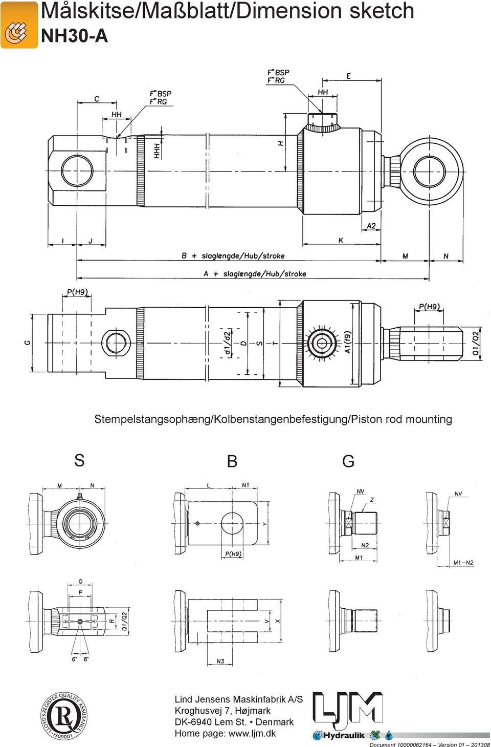
7 Målskema/Maßtabelle/Dimension table NH30-A D A B D ø 25 ø 40 ø 50 ø 63 ø 80 ø 100 ø 125 ø 140 ø 160 ø 180 ø 200 ø 250 d1\d2 ø 12\ø 16 ø 20\ø 25 ø 25\ø 35 ø 30\ø 40 ø 40\ø 50 ø 50\ø 65 ø 65\ø 80 ø 70\ø 90 ø 80\ø 100 ø 90\ø 110 ø 100\ø 125 ø 125\ø 150 C E F 1/4 RG 3/8 RG 3/8 RG 1/2 RG 1/2 RG 3/4 RG 3/4 RG 1 RG 1 RG 1 1/4 RG 1 1/4 RG 1 1/4 RG G H HH ø 20 ø 25 ø 25 ø 30 ø 30 ø 40 ø 40 ø 50 ø 50 ø 60 ø 60 ø 60 HHH I J K L M M N N N N O ø 15 ø 24 ø 29 ø 34 ø 39 ø 50 ø 66 ø 77 ø 77 ø 89 ø 89 ø 109 P ø 12 ø 20 ø 25 ø 30 ø 35 ø 45 ø 60 ø 70 ø 70 ø 80 ø 80 ø 100 Q1\Q2 15\20 25\30 30\40 35\45 45\55 55\70 70\85 75\95 85\105 95\ \ \155 R S ø 32 ø 50 ø 60 ø 75 ø 95 ø 115 ø 145 ø 160 ø 185 ø 205 ø 230 ø 285 T ø 45 ø 60 ø 75 ø 90 ø 105 ø 130 ø 159 ø 185 ø 202 ø 230 ø 250 ø 320 V X Y Z M12x1.25 M16x2 M22x2 M24x2 M36x2 M42x2 M52x2 M56x2 M70x2 M80x3 M80x3 M100x3 A1 ø 39 ø 54 ø 69 ø 84 ø 99 ø 125 ø 145 ø 165 ø 185 ø 205 ø 240 ø 295 A * * * NV 10\13 17\19 22\27 24\32 36\42 46\50 55\60 60\80 70\90 80\100 85\ \135 1* Tillæg for A og B, når cylinder skal være med dæmpning i top eller bund. 2* Tillæg for A og B, når cylinder skal være med dæmpning i top og bund. 3* Tillæg for A og B, når dobbeltvirkende cylinder er med læbepakning (LP), eller Heavy Duty (MW) for NH30-25 T.O.M. NH Alle angivne mål er i (mm). Ret til ændringer forbeholdes. 1* Addition for A and B when cylinder is to have damping in top or bottom. 2* Addition for A and B when cylinder is to have damping in top and bottom. 3* Addition for A and B when double-acting cylinder has lip seals (LP) or Heavy Duty (MW) for NH30-25 to NH both included. Unless otherwise specified, all dimensions are in (mm). Right to alterations reserved. 1* Zusatz für A und B, wenn der Zylinder am Kopf oder am Boden eine Dämfung hat. 2* Zusatz für A und B, wenn der Zylinder am Kopf und am Boden eine Dämpfung hat. 3* Zusatz für A und B, wenn der doppelt wirkende Zylinder mit einer Lippendichtung (LP) ausgestattet ist, oder wenn der Zylinder Stangenführungsbänder (MW) hat von NH30-25 bis NH Alle angegebenen Maße sind in (mm). Wir behalten uns das Recht auf nderungen vor.

8 Målskitse/Maßblatt/Dimension sketch NH30-B Stempelstangsophæng/Kolbenstangenbefestigung/Piston rod mounting S A G

9 Målskema/Maßtabelle/Dimension table NH30-B D A B d1\d2 12/16 20/25 25/35 30/40 40/50 50/65 65/80 70/90 80/100 90/ / /150 C E F 1/4 RG 3/8 RG 3/8 RG 1/2 RG 1/2 RG 3/4 RG 3/4 RG 1 RG 1 RG 1 1/4 RG 1 1/4 RG 1 1/4 RG H HH HHH I J J K L M M N N N N O ø 15 ø 24 ø 29 ø 34 ø 39 ø 50 ø 66 ø 77 ø 77 ø 89 ø 89 ø 109 P ø 12 ø 20 ø 25 ø 30 ø 35 ø 45 ø 60 ø 70 ø 70 ø 80 ø 80 ø 100 Q1\Q2 15\20 25\30 30\40 35\45 45\55 55\70 70\85 75\95 85\105 95\ \ \155 R S ø 32 ø 50 ø 60 ø 75 ø 95 ø 115 ø 145 ø 160 ø 185 ø 205 ø 230 ø 285 T ø 45 ø 60 ø 75 ø 90 ø 105 ø 130 ø 159 ø 185 ø 202 ø 230 ø 250 ø 320 V X Y Z M12x1.25 M16x2 M22x2 M24x2 M36x2 M42x2 M52x2 M56x2 M70x2 M80x3 M80x3 M100x3 A1 ø 39 ø 54 ø 69 ø 84 ø 99 ø 125 ø 145 ø 165 ø 185 ø 205 ø 240 ø 295 A * * * NV 10\13 17\19 22\27 24\32 36\42 46\50 55\60 60\80 70\90 80\100 85\ \135 1* Tillæg for A og B, når cylinder skal være med dæmpning i top eller bund. 2* Tillæg for A og B, når cylinder skal være med dæmpning i top og bund. 3* Tillæg for A og B, når dobbeltvirkende cylinder er med læbepakning (LP), eller Heavy Duty (MW) for NH30-25 T.O.M. NH Alle angivne mål er i (mm). Ret til ændringer forbeholdes. 1* Addition for A and B when cylinder is to have damping in top or bottom. 2* Addition for A and B when cylinder is to have damping in top and bottom. 3* Addition for A and B when double-acting cylinder has lip seals (LP) or Heavy Duty (MW) for NH30-25 to NH both included. Unless otherwise specified, all dimensions are in (mm). Right to alterations reserved. 1* Zusatz für A und B, wenn der Zylinder am Kopf oder am Boden eine Dämfpung hat. 2* Zusatz für A und B, wenn der Zylinder am Kopf und am Boden eine Dämpfung hat. 3* Zusatz für A und B, wenn der doppelt wirkende Zylinder mit einer Lippendichtung (LP) ausgestättet ist, oder wenn der Zylinder Stangenführungsbänder (MW) hat von NH30-25 bis NH Alle angegebenen Maße sind in (mm). Wir behalten und das Recht auf Änderungen vor.

10 Målskitse/Maßblatt/Dimension sketch NH30-C Stempelstangsophæng/Kolbenstangenbefestigung/Piston rod mounting S A B
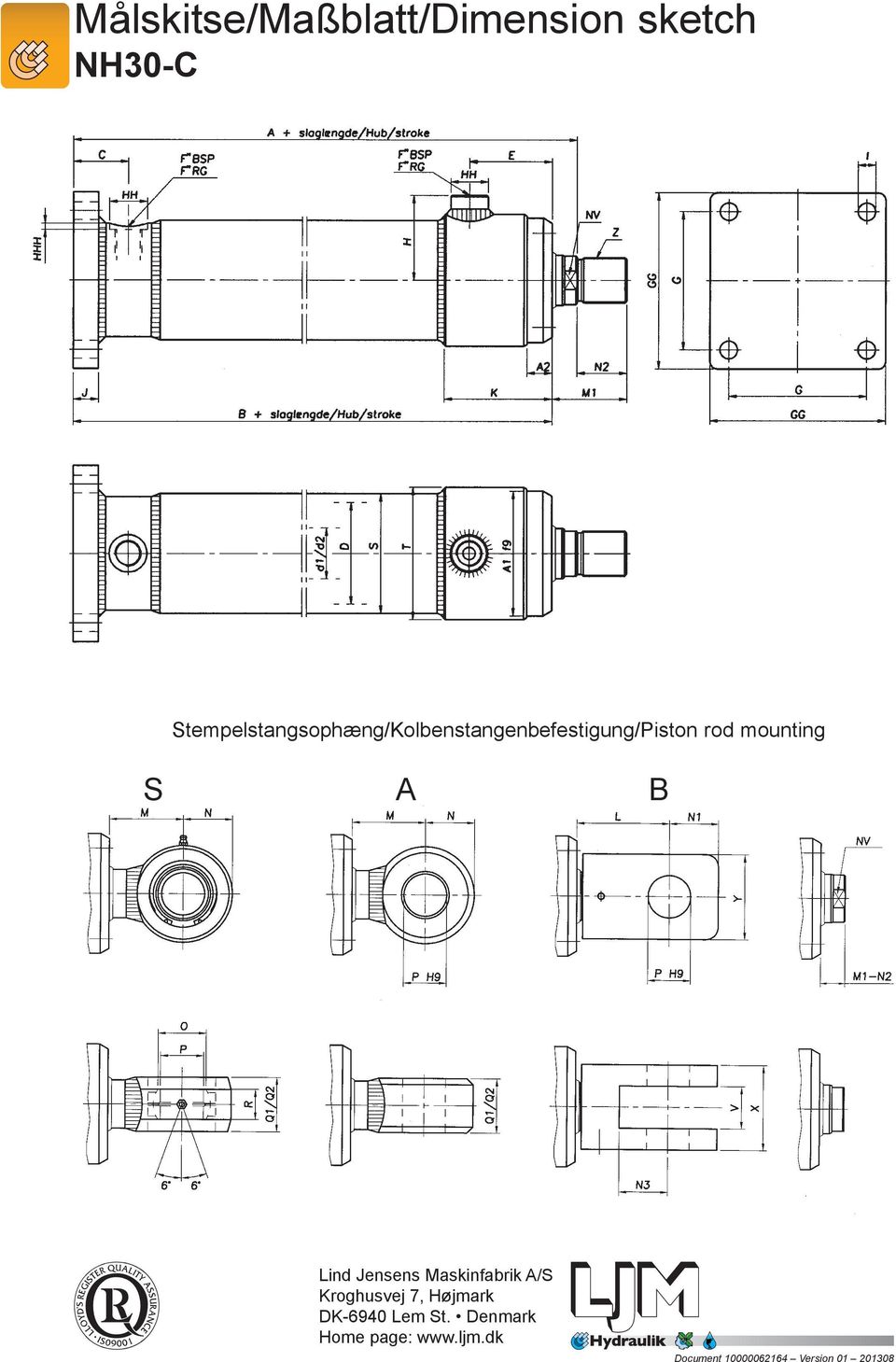
11 Målskema/Maßtabelle/Dimension table NH30-C D A B d1\d2 12/16 20/25 25/35 30/40 40/50 50/65 65/80 70/90 80/100 90/ / /150 C E F 1/4 RG 3/8 RG 3/8 RG 1/2 RG 1/2 RG 3/4 RG 3/4 RG 1 RG 1 RG 1 1/4 RG 1 1/4 RG 1 1/4 RG G GG H HH HHH I J K L M M N N N N O P Q1\Q2 15\20 25\30 30\40 35\45 45\55 55\70 70\85 75\95 85\105 95\ \ \155 R S T V X Y Z M12x1.25 M16x2 M22x2 M24x2 M36x2 M42x2 M52x2 M56x2 M70x2 M80x3 M80x3 M100x3 A A * * * NV 10\13 17\19 22\27 24\32 36\42 46\50 55\60 60\80 70\90 80\100 85\ \135 1* Tillæg for A og B, når cylinder skal være med dæmpning i top eller bund. 2* Tillæg for A og B, når cylinder skal være med dæmpning i top og bund. 3* Tillæg for A og B, når dobbeltvirkende cylinder er med læbepakning (LP), eller Heavy Duty (MW) for NH30-25 T.O.M. NH Alle angivne mål er i (mm). Ret til ændringer forbeholdes. 1* Addition for A and B when cylinder is to have damping in top or bottom. 2* Addition for A and B when cylinder is to have damping in top and bottom. 3* Addition for A and B when double-acting cylinder has lip seals (LP) or Heavy Duty (MW) for NH30-25 to NH both included. Unless otherwise specified, all dimensions are in (mm). Right to alterations reserved. 1* Zusatz für A und B, wenn der Zylinder am Kopf oder am Boden eine Dämpfung hat. 2* Zusatz für A und B, wenn der Zylinder am Kopf und am Boden eine Dämpfung hat. 3* Zusatz für A und B, wenn der doppelt wirkende Zylinder mit einer Lippendichtung (LP) ausgestattet ist, oder wenn der Zylinder Stangenführungsbänder (MW) hat von NH30-25 bis NH Alle angegebenen Maße sind in (mm). Wir behalten uns das Recht auf Änderungen vor.

12 Målskitse/Maßblatt/Dimension sketch NH30-F Stempelstangsophæng/Kolbenstangenbefestigung/Piston rod mounting S A B
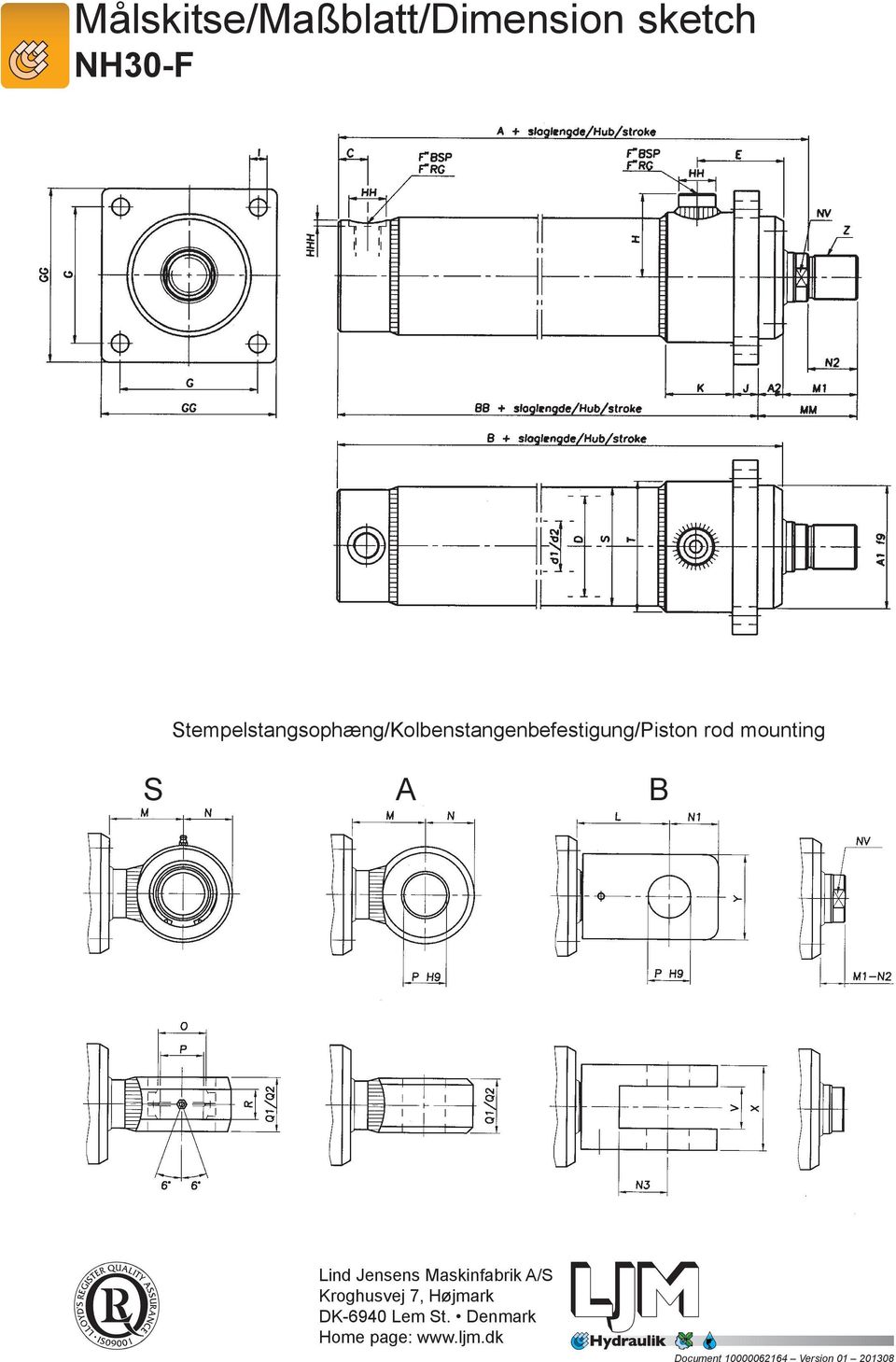
13 Målskema/Maßtabelle/Dimension table NH30-F D A B BB d1\d2 12/16 20/25 25/35 30/40 40/50 50/65 65/80 70/90 80/100 90/ / /150 C E F 1/4 RG 3/8 RG 3/8 RG 1/2 RG 1/2 RG 3/4 RG 3/4 RG 1 RG 1 RG 1 1/4 RG 1 1/4 RG 1 1/4 RG G GG H HH HHH I J K L M M MM N N N N O P Q1\Q2 15\20 25\30 30\40 35\45 45\55 55\70 70\85 75\95 85\105 95\ \ \155 R S T V X Y Z M12x1.25 M16x2 M22x2 M24x2 M36x2 M42x2 M52x2 M56x2 M70x2 M80x3 M80x3 M100x3 A A * * * NV 10\13 17\19 22\27 24\32 36\42 46\50 55\60 60\80 70\90 80\100 85\ \135 1* Tillæg for A og B, når cylinder skal være med dæmpning i top eller bund. 2* Tillæg for A og B, når cylinder skal være med dæmpning i top og bund. 3* Tillæg for A og B, når dobbeltvirkende cylinder er med læbepakning (LP), eller Heavy Duty (MW) for NH30-25 T.O.M. NH Alle angivne mål er i (mm). Ret til ændringer forbeholdes. 1* Addition for A and B when cylinder is to have damping in top or bottom. 2* Addition for A and B when cylinder is to have damping in top and bottom. 3* Addition for A and B when double-acting cylinder has lip seals (LP) or Heavy Duty (MW) for NH30-25 to NH both included. Unless otherwise specified, all dimensions are in (mm). Right to alterations reserved. 1* Zusatz für A und B, wenn der Zylinder am Kopf oder am Boden eine Dämpfung hat. 2* Zusatz für A und B, wenn der Zylinder am Kopf und am Boden eine Dämpfung hat. 3* Zusatz für A und B, wenn der doppelt wirkende Zylinder mit einer Lippendichtung (LP) ausgestattet ist, oder wenn der Zylinder Stangenführungsbänder (MW) hat von NH30-25 bis NH Alle angegebenev Maße sind in (mm). Wir behalten und das Recht auf Änderungen vor.

14 Målskitse/Maßblatt/Dimension sketch NH30-V Stempelstangsophæng/Kolbenstangenbefestigung/Piston rod mounting S A B
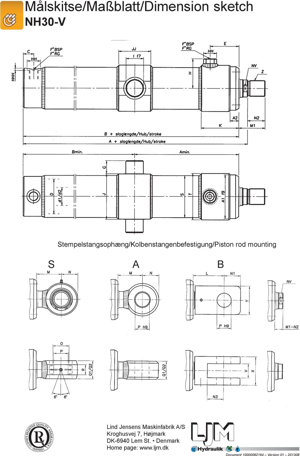
15 Målskema/Maßtabelle/Dimension table NH30-V D A * A min B B min 64,5 62, , d1\d2 ø 12\ø 16 ø 20\ø 25 ø 25\ø 35 ø 30\ø 40 ø 40\ø 50 ø 50\ø 65 ø 65\ø 80 ø 70\ø 90 ø 80\ø 100 ø 90\ø 110 ø 100\ø 125 ø 125\ø 150 C E F 1/4 RG 3/8 RG 3/8 RG 1/2 RG 1/2 RG 3/4 RG 3/4 RG 1 RG 1 RG 1 1/4 RG 1 1/4 RG 1 1/4 RG G H HH HHH I (f7) J K L M M N N N N O P Q1\Q2 15\20 25\30 30\40 35\45 45\55 55\70 70\85 75\95 85\105 95\ \ \155 R S T V X Y Z M12x1.25 M16x2 M22x2 M24x2 M36x2 M42x2 M52x2 M56x2 M70x2 M80x3 M80x3 M100x3 A A * * * JJ NV 10\13 17\19 22\27 24\32 36\42 46\50 55\60 60\80 70\90 80\100 85\ \135 Min. Slaglængde / Hub / stroke * Tillæg for A og B, når cylinder skal være med dæmpning i top eller bund. 2* Tillæg for A og B, når cylinder skal være med dæmpning i top og bund. 3* Tillæg for A og B, når dobbeltvirkende cylinder er med læbepakning (LP), eller Heavy Duty (MW) for NH30-25 T.O.M. NH Alle angivne mål er i (mm). Ret til ændringer forbeholdes. 1* Addition for A and B when cylinder is to have damping in top or bottom. 2* Addition for A and B when cylinder is to have damping in top and bottom. 3* Addition for A and B when double-acting cylinder has lip seals (LP) or Heavy Duty (MW) for NH30-25 to NH both included. Unless otherwise specified, all dimensions are in (mm). Right to alterations reserved. 1* Zusatz für A und B, wenn der Zylinder am Kopf oder am Boden eine Dämpfung hat. 2* Zusatz für A und B, wenn der Zylinder am Kopf und am Boden eine Dämpfung hat. 3* Zusatz für A und B, wenn der doppelt wirkende Zylinder mit einer Lippendichtung (LP) ausgestattet ist, oder wenn der Zylinder Stangenführungsbänder (MW) hat von NH30-25 bis NH Alle angegebenen Masse sind in (mm). Wir behalten uns das Recht von Änderungen vor. * Vippebeslagplacering = A min + * Anbringung der mittlere Schwenkung = A min + * Position of trunnion mounting = A min + { M L { M L { M L * dette mål opgives ved bestilling. (M1 N2) * bitte an Bestellung aufgeben. (M1 N2) * this measurement to be stated when ordering. (M1 N2)

16 Målskitse/Maßblatt/Dimension sketch NH30-H C HH F"BSP F"RG F"BSP F"RG HH E NV H Z K A2 M1 N2 D d1/d2 S T A1 f9 HHH II I GG G JJ GGG GGG J B + slaglængde/hub/stroke A + slaglængde/hub/stroke BB + slaglængde/hub/stroke A3 Stempelstangsophæng/Kolbenstangenbefestigung/Piston rod mounting S A B

17 Målskema/Maßtabelle/Dimension table NH30-H D A B BB d1\d2 12/16 20/25 25/35 30/40 40/50 50/65 65/80 70/90 80/100 90/ / /150 C E F 1/4 RG 3/8 RG 3/8 RG 1/2 RG 1/2 RG 3/4 RG 3/4 RG 1 RG 1 RG 1 1/4 RG 1 1/4 RG 1 1/4 RG G H HH HHH I 8, II J JJ K L M M N N N N NV 10/13 17/19 22/27 24/32 36/42 46/50 55/60 60/80 70/90 80/100 85/ /135 O P Q1\Q2 15\20 25\30 30\40 35\45 45\55 55\70 70\85 75\95 85\105 95\ \ \155 R S T V X Y Z M12x1.25 M16x2 M22x2 M24x2 M36x2 M42x2 M52x2 M56x2 M70x2 M80x3 M80x3 M100x3 A A A * * * GG GGG * Tillæg for A, B og BB når cylinder skal være med dæmpning i top eller bund. 2* Tillæg for A, B og BB når cylinder skal være med dæmpning i top og bund. 3* Tillæg for A, B og BB når dobbeltvirkende cylinder er med læbepakning (LP), eller Heavy Duty (MW) for NH30-25 T.O.M. NH Alle angivne mål er i (mm). Ret til ændringer forbeholdes. 1* Addition for A, B and BB when cylinder is to have damping in top or bottom. 2* Addition for A, B and BB when cylinder is to have damping in top and bottom. 3* Addition for A, B and BB when double-acting cylinder has lip seals (LP) or Heavy Duty (MW) for NH30-25 to NH both included. Unless otherwise specified, all dimensions are in (mm). Right to alterations reserved. 1* Zusatz für A, B und BB, wenn der Zylinder am Kopf oder am Boden eine Dämpfung hat. 2* Zusatz für A, B und BB, wenn der Zylinder am Kopf und am Boden eine Dämpfung hat. 3* Zusatz für A, B und BB, wenn der doppelt wirkende Zylinder mit einer Lippendichtung (LP) ausgestattet ist, oder wenn der Zylinder Stangenführingsbänder (MW) hat von NH30-25 bis NH Alle angegebenen Maße sind in (mm). Wir behalten uns das Recht auf Änderungen vor.

18 E HH F"BSP F"RG F"BSP F"RG HH NV H A2 Ex.: NH30-_ D - D/d x L - S - H K (M1-N2) B + slaglængde/hub/stroke M + slagl./hub/stroke N O P A1 f9 T S D d1/d2 R Q1/Q2 H Målskitse/Maßblatt/Dimension sketch NH30-D NB; Cylinderen kan leveres med ophæng på cylinderrør af typerne (F) frontflange, (V) vippebeslag og (H) fodflange. Se dimensioner i katalogblade for NH30-F, NH30-V og NH30-H. Som standard leveres cylinderen med "glat" stempelstangsende modsat valgt stempelstang med ophæng. Efter ønske kan der også leveres med gevind (G)! NB; The cylinder is with optional mounting on cylinder tube according to type (F) front flange, (V) trunnion mounting and (H) foot mounting. See the dimension in the catalogue pages about NH30-F, NH30-V and NH30-H. As standard the cylinder will be delivered with plain piston rod in opposite end of chosen piston rod end with mounting. By request the piston rod can also be delivered threaded (G). NB; Der Zylinder ist mit Befestigung auf Zylinderrohr von den Typen (F) Kopfflansch, (V) Mittlere Schwenkung und (H) Fußbefestigung möglich. Siehe Maßen in die Katalogseiten über NH30-F, NH30-V und NH30-H. Die Zylinder können nur mit auf einer Seite befindlichen Kolbenstangenbefestigung (Montagegrund) A und S geliefert werden. Die andere Seite kann als glattes Kolbenstangenende oder mit Gewinde ausgeführt werden. Stempelstangsophæng/Kolbenstangenbefestigung/Piston rod mounting 6 6 A P(H9) G-S B P(H9) G NV Z M N M2 M3 N L N1 N2 M1 O P Q1/Q2 R Q1 V X Y N3
! NB; The cylinder is with optional mounting on cylinder tube according to type (F) front flange, (V) trunnion mounting and (H) foot mounting.")
19 Målskema/Maßtabelle/Dimension table NH30-D Index D B D d1\d2 12/16 20/25 25\35 30/40 40/50 50/65 65/80 70/90 80/100 90/ / /150 E F 1/4 3/8 3/8 1/2 1/2 3/4 3/ /4 1 1/4 1 1/4 H HH K L M MX M M M N N N N O P Q1\Q2 15/20 25/30 30/40 35/45 45/55 55/70 70/85 75/95 85/105 95/ / /155 R S T V X Y Z M12x1.25 M16x2 M22x2 M24x2 M36x2 M42x2 M52x2 M56x2 M70x2 M80x3 M80x3 M100x3 A1 ø 39 ø 54 ø 69 ø 84 ø 99 ø 125 ø 145 ø 165 ø 185 ø 205 ø 240 ø 295 A NV 10/13 17/19 22/27 24/32 36/42 46/50 55/60 60/80 70/90 80/100 85/ /135 Alle angivne mål er i (mm). Ret til ændringer forbeholdes. Unless otherwise specified, all dimensions are in (mm). Right to alterations reserved. Alle angegebenen Maße sind in (mm). Wir behalten uns das Recht auf Änderungen vor.

20 Målskema/Masstabelle/Dimension table Gevindflange: C for cylindertype NH 30 Gewindeflansch: C für Zylindertyp NH 30 Threaded flange: C for cylinder model NH 30 Gevindflange C passer til alle NH30 cylindre med gevind på stempelstang Gewindeflansch C passend zu allen NH30 Zylindern mit Gewinde an der Kolbenstange Threaded flange C fits all NH30 cylinders with threaded piston rod CYL. ZYL. Index A B C D E F G H M12X1,25 M16X2,0 M22X2,0 M24X2,0 M36X2,0 M42X2,0 M52X2,0 M56X2,0 M70X2,0 M80X3,0 M80X3,0 M100X3,0 I M5X0,8 M5X0,8 M5X0,8 M6X1,0 M6X1,0 M6X1,0 M8X1,25 M8X1,25 M8X1,25 M8X1,25 M8X1,25 M8X1,25

21 Målskema/Masstabelle/Dimension table Ledlejehoved for cylindertype NH 30 Gelenklagerkopf für Zylindertyp NH 30 Spherical bearing head for cylinder model NH 30 J Ledlejehoved passer til alle NH 30 cylindre med gevind på stempelstang Gelenklagerkopf passend zu allen NH 30 Zylindern mit Gewinde an der Kolbenstange The spherical bearing head fits all NH 30 cylinders with threaded piston rod Index D A , B 41, N 17, , E R Q P O C M5 M6 M6 M6 M6 M6 M6 M6 M8 M8 M8 M8 Z M12 1,25 M16 2 M22 2 M24 2 M36 2 M42 2 M52 2 M56 2 M70 2 M80 3 M80 3 M100 3 J , ,5 98
22 Målskema/Masstabelle/Dimension table Lejeblok for cylindertype NH30 Lagerbock für Zylindertyp NH30 Bearing block for cylindermodel NH30
23 Specification form 4 Order code NH30 NH30-X-X-X-D/d x L-X-X-X-X-X-X-()-X Model: Internal code: Basic types: Blank: No mounting S: Spherical bearing A: Fixed mounting *** B: Fork. mounting *** C: Bottom flange *** F: Front flange *** V: Trunnion mounting *** H: Foot mounting *** S(K): Bronze sphere in bearing head S(B): Bronze bush S(R): Stainless steel sph. bearing.** Function: D: Double acting E1: Single acting, compressive E2: Single acting, tractive Bore: Piston rod diameter: Stroke: Position of trunnion mounting: Digit: Distance from tipping trunnion to mounting on piston rod Digit: Length of spacer bush Digit: in() = piston rod extension H: Through going rod *Special seals: TN: Teflon TV: Teflon-Viton LP: Lip seals on piston MW: Heavy duty PK-40: C. "B": Damping in bottom "T": Damping in top Piston rod materials: NI: Nickel/Chrome R: Stainless steel RS: Stainless/acid proof Blank: Steel (all hard-chromeplated) Piston rod mounting: S: Spherical bearing A: Fixed mounting B: Fork. mounting C: Threaded flange G: Thread S(K): Spherical bearing with bronze S(B): Fixed bronze bush S(R): Stainless steel sph. bearing. ** Blank: Piston rod without mounting * Special seals to be used under extreme conditions, i.e. where pressure, villosities, temperature and pressure media fall outside the technical specifications. Ask the adviser for guidance. ** The cylinder has to work with lower working pressure due to rust proof bearing. Please contact LJM Hydraulic. *** Not type approved by Germanischer Lloyd (GL) as standard.
24 Lagerliste Lagerliste Stocktaking NH30-SD-D/dxL-s Bilag b Anlage b Appendix b D/d L /12 40/20 40/25 50/25 50/35 63/30 63/40 80/40 80/50 100/50 100/65
25 Typegodkendelse/ Type approval/ Typengenehmigung NH30 Type approval - Germanischer Lloyd
26 Installationseksempler, Anwendungsbeispiele, Examples of installations NH30
27 Oversigtsblad Übersicht Design features for NH 75 cylinder für NH 75 Zylinder for NH 75 cylinder PMC Oversigtsblad * Grundtyper/ Stempelstangsophæng/ Zylinderbefestigung/ Kolbenstangenbefestigung/ Basic types Piston rod mounting S S S(C) S(C)
28
29 Technical specification 21- NH75 tek. spec. GB 06/08/04 7:32 Side 1 NH75 NH 75 hydraulic cylinder Technical specification: General: NH75 NH75 is a double is a double acting acting hydraulic hydrauliccylinder. cylinder. Approved by by Det Det Norske Veritas (DNV). Application: Application: Marine Marine Offshore Offshore and and Mobile. Mobile. Bore Bore from from Ø to to Ø mm. mm. Construction: (See (See sketch). sketch). Cylinder tube: Steel Steel S355J2G3C E295GC (SIS 2172). Inside Honed surface: to Ra max. Ra max 0,3 µm. 0,3 μm. Internal tolerance H9. H9. Piston rod: Steel Steel 20MnV6 20MnV6 (SIS (SIS 2142). 2142). Stainless steel X4CrNiMo (SIS 2387). Hard Stainless chrome steel/acid plated. proved steel X3CrNiMoN (SIS 2324). Seals: Hard chrom plated. (Recognized manufactures). Nickel and hard chrom plated. Mountings: Seals: (See (Recognized design features). manufactures). S: Spherical eye in steel. S(C): Mountings: Spherical eye in composite. S(K): (See Spherical design features). bearing with bronze inner ring S: Spherical eye in steel. Connections: S(C): Spherical eye in komposite. Cylindrical BSP thread, according to DIN Connections: 3852: Part 2. November Cylindrical BSP thread, Operating according DIN pressure: 3852: Teil 2. novb Design pressure 250 Bar. Operating pressure: Piston Designpressure velocity: 250 Bar. Piston velocity: Max. piston velocity: 0,3 m/ sec For higher speed, please ask LJM. Max. piston velocity: 0,3 m/s. Operating For higher velocity temperature: use special seals. Temperature range: - 20 C to + 80 C. For Operating higher/lower temperature: temperatures, please ask LJM. Temperature range: - 20 C to + 80 C. Pressure For higher/lower medium: temperatures use special seals. Hydraulic oil on mineral oil base. Pressure medium: If another medium is to be used, please state when ordering. Hydraulic oil on mineral oil base. If another medium is to be used, please state Test: when ordering. The cylinders are pressure tested at 350 Bar and tested Test: for proper function, before leaving the factory. The cylinders are pressure tested at 350 Bar Order and tested code: for proper function, before leaving the See factory. specification form 13. Order kode: See specification form 13., DK-6940 Lem St. Tlf.: Fax:
30 NH 75 Hydraulikcylinder Hydraulikzylinder Hydraulic cylinder Målskitse/Maßblatt/Dimension sketch NH75-S Målskitse/Massblatt/Dimension sketch Diameter/Bohrung/Bore: mm Diameter/Bohrung/Bore: mm 08.04
31 Målskema/Maßtabelle/Dimension table Målskema/Masstabelle/Dimension NH75-S table D Index A A ,9 355,9 368 A B C 62, D d1/d2 25/32 30/40 40/50 50/65 65/80 70/90 80/100 90/ / / / / / /220 E 59,5 60,5 77,5 80,5 97,5 112,5 120,5 132,5 142,5 147,5 156,5 167,5 177,5 179,5 F 3/8 1/2 1/2 1/2 3/4 3/4 3/ /4 1 1/4 H 45 52,5 62,5 72, , , ,5 206,3 212,5 HH HHH 2,1 2,5 2,5 2,5 2,5 2,5 2,5 2,5 2,5 2,5 2,5 2,5 2,5 2,5 I J 35,5 35,5 40, J M N , O , P Q R ~R S ,9 355,9 368 Alle angivne mål er i (mm). Ret til ændringer forbeholdes. Alle angegebenen Maße sind in (mm). Wir behalten uns das Recht auf Änderungen vor. Unless otherwise specified, all dimensions are in (mm). Right to alterations reserved.
32 NH 75 Hydraulikcylinder Hydraulikzylinder Hydraulic cylinder NH 75 Hydraulikcylinder Hydraulikzylinder Hydraulic cylinder Målskitse/Maßblatt/Dimension sketch Målskitse/Massblatt/Dimension NH75-S(C) Målskitse/Massblatt/Dimension sketch sketch
33 D D Index Index Målskema/Maßtabelle/Dimension table Målskema/Masstabelle/Dimension Målskema/Masstabelle/Dimension NH75-S(C) table table A A A1 A ,9 323,9 355,9 355, A2 A B BD D Index C C 62, , Index A D D A A1 d1/d2 d1/d / / / / / / / / / / / / / / / / / / , / , / A1 A2 E E 60 59,5 8 59, ,5 8 60, , , , , , , , , , , , , , , , , , ,5 323,9 167, ,5 355,9 177, , , ,5 A2 B F F /8 3/ /2 1/ /2 1/ /2 1/ /4 3/ /4 3/ /4 3/ /4 1 1/ /4 1 1/4 B C H H , , , , , , , , , , , , , , , , ,5 C D HH HH62, D d1/d2 HHH HHH 50 25/32 2,1 2, /40 2,5 2, /50 2,5 2, /65 2,5 2, /80 2,5 2, /90 2, /100 2, /110 2,5 2, /125 2,5 2, /140 2, /160 2, /180 2, /200 2,5 2, /220 2,5 2,5 d1/d2 E I I 25/32 59,5 4030/40 60,5 4040/50 77,5 47,5 50/65 47,5 80, / ,5 70/90 112,5 80/ ,5 90/ ,5 100/ ,5 110/ ,5 125/ ,5 140/ ,5 160/ ,5 180/ , E F J J 59,5 3/8 35,5 35,5 60,5 1/2 35,5 35,5 77,5 1/2 40,5 40,5 80,5 1/2 6597,5 3/ ,5 70 3/ ,5 73 3/ , , , , , , /4 179, /4 170 F H J1 J13/ /2 52,5 451/2 62,5 521/2 72,5 803/ /4 100,5 933/ , , /4 206, /4 212, H HH M M , , , , , , , , HH HHH N N 25 2, , ,5 47,5 47,5 30 2, , , , , , , , , , , HHH I O O 2,1 40, ,35 2,5 40, ,35 2,5 50,75 47,5 50,75 2,5 55, ,9 2,5 67, ,08 2,5 75, ,99 2,5 84, ,85 2,5 96, ,05 2,5 107, ,5 118, ,5 132, ,5 148, ,5 160, ,1 2,5 169, I J P P 40 35, ,5 3247,5 40, J J1 Q Q 35, , , J1 M R R M N ~R1 ~R , N O S S 40 40, , ,5 50, , , , , , , , , ,36 323,9 323, ,1 355,9 355, , O P 40, , , , , , , , , , , , , , P Q Q R R ~R ~R1 S , , S ,9 355,9 368 Alle angivne mål er i (mm). Ret til ændringer forbeholdes. Alle angegebenen Maße sind in (mm). Wir behalten uns das Recht auf Änderungen vor. Unless otherwise specified, all dimensions are in (mm). Right to alterations reserved.
34 Specification form 13 Order code NH75 Type: Design code Basic types: Blank: No mounting S: Spherical bearing S(C): Spherical bearing with composite S(K) : Spherical bearing with bronze * Special seals: TN: Teflon TV: Teflon-viton PK-40: C. Function: D: Double acting E 1 : Single acting, compressive E 2 : Single acting, tractive Cylinder bore: Piston rod diameter: Stroke: Limited length of stroke according to DNV type approval Piston rod material: R: Stainless Blank: Steel RS: (all Stainless/ hard chrome acid plated) proof Digit: Length of distance bush Digit: in () = Extension of piston rod Piston rod mounting: S: Spherical bearing S(C): Spherical bearing with composite * Special seals to be used under extreme conditions, i.e. where pressure, volocities, temperature and pressure media fall outside the technical specifications. Ask the adviser for guidance.
35 Typegodkendelse/ Typengenehmigung/ Type approval NH75 DNV - Det Norske Veritas
36 Installationseksempler, Anwendungsbeispiele, Examples of installations NH75
MOBIL SCHWER BETRIEB NH30 NH75. Lind Jensens Maskinfabrik A/S Kroghusvej 7, Højmark DK-6940 Lem St. Denmark Home page:
 MOBIL SCHWER BETRIEB NH30 NH75 Oversigtsblad Übersicht Design features for NH 30 cylinder für NH 30 Zylinder for NH 30 cylinder *Grundtyper/ Stempelstangsophæng/ Zylinderbefestigung/ Kolbenstangenbefestigung/
ROSTFREI-NIRO NH46 NH47 NH54 NH55. Lind Jensens Maskinfabrik A/S Kroghusvej 7, Højmark DK-6940 Lem St. Denmark Home page:
 ROSTFREI-NIRO NH46 NH47 NH54 NH55 Oversigtsblad Übersicht Design features for NH 54/55 cylinder für NH 54/55 Zylinder for NH 54/55 cylinder * Grundtyper/ Stempelstangsophæng/ Zylinderbefestigung/ Kolbenstangenbefestigung/
TECHNISCHE DATEN TYP HET TECHNICAL DATA. Single-acting hydraulic telescopic cylinder
 TECHNISCHE DATEN TYP HET Hydraulisch einfachwirkender Teleskopzylinder TECHNICAL DATA TYP HET Single-acting hydraulic telescopic cylinder, bis zu 5 Stufen, Nenndruck max. 200 bar. Sonderausführung nach
TECHNISCHE DATEN TYP D TECHNICAL DATA
 TECHNISCHE DATEN TYP D Hydraulik Differentialzylinder ohne Endlagendämpfung TECHNICAL DATA TYP D Hydraulic differential cylinder without end position damping Hydraulik Differentialzylinder ohne Endlagendämpfung,
TECHNICAL DATA. Double-acting pneumatic telescopic cylinder
 TECHNISCHE DATEN TYP PDT Pneumatisch doppeltwirkender Teleskopzylinder TECHNICAL DATA TYP PDT Double-acting pneumatic telescopic cylinder Pneumatisch doppeltwirkende Teleskopzylinder mit Endlagendämpfung,
TECHNISCHE DATEN TYP PLU. Einfachwirkende auf Druck arbeitender Hydraulikzylinder, TECHNICAL DATA
 TECHNISCHE DATEN TYP PLU Einfachwirkend auf Druck arbeitender Hydraulikzylinder TECHNICAL DATA TYP PLU Single-acting, pressure-operated hydraulic cylinder Einfachwirkende auf Druck arbeitender Hydraulikzylinder,
Paknings vejledning Dichtungsanleitung Seal Guidance
 Paknings vejledning Dichtungsanleitung Seal Guidance Standardpakninger Standarddichtungen Standard seals Heavy Duty pakninger Dichtung für schweren Einsatz Heavy duty seals MW LP Læbepakninger på manchetsko
Rohrschieber mit Schließfeder Slide Valve spring loaded
 Rohrschieber mit Schließfeder Slide Valve spring loaded Rohrschieber als automatisches Entlüftungsventil Slide Valve as automatic air relief valve Type: RSF DN: 50 300 (2 12 ) PN: 16 160 (Class 150 900)
pneumatische oder hydraulische präzisionsführungseinheiten pneumatic or hydraulic precision guide rails
 91 Katalog 01 Standardführungen Catalog 01 standard ball-bearing 10 pneumatische oder hydraulische präzisionsführungseinheiten pneumatic or hydraulic precision guide rails > präzisionsführungseinheit 23
Plungerzylinder ZE (300 bar) Plunger Cylinder ZE (300 bar)
 Plunger Cylinder ZE (300 bar)") Plungerzylinder ZE (300 bar) Plunger Cylinder ZE (300 bar) Einfachwirkender Zylinder Rundbauweise Plunger -Ø: 30 bis 100 mm Hublänge bis 3.000 mm Single Acting Cylinder Round head type Plunger-Ø: 30 to
Plungerzylinder ZE (300 bar) Plunger Cylinder ZE (300 bar) Einfachwirkender Zylinder Rundbauweise Plunger -Ø: 30 bis 100 mm Hublänge bis 3.000 mm Single Acting Cylinder Round head type Plunger-Ø: 30 to
c a Grundbezeichnung Kolben-Ø (mm)
") i H YD R A U LI KZYLI N D E R SPANNEN STANZEN BIEGEN BEWEGEN BLOCKZYLINDER DOPPELTWIRKEND TYP 600 MIT LÄNGSBOHRUNGEN g SW o c a d b h1 L1+Hub h2 L2 TYP 600 Betriebsdruck max. 500 bar. Grundbezeichnung
i H YD R A U LI KZYLI N D E R SPANNEN STANZEN BIEGEN BEWEGEN BLOCKZYLINDER DOPPELTWIRKEND TYP 600 MIT LÄNGSBOHRUNGEN g SW o c a d b h1 L1+Hub h2 L2 TYP 600 Betriebsdruck max. 500 bar. Grundbezeichnung
Zubehör Accessories Accessoires
 Seite Page Page 14/2 DA 14/4 Allgemeine Merkmale Drehantrieb General parameters Rotary drive unit Caractéristiques générales Servomoteur rotatif + 16 Zubehör Accessories Accessoires 14/0 Drehantrieb Rotary
Pneumatic linear actuator - series MCB with cylinder Pneumatischer Linearantrieb Serie MCB mit Zylinder
 Technische Eigenschaften: - Betriebsdruck: 2 7 bar - Wiederholgenauigkeit: 0.1 - Betriebstemperaturbereich von 5 C bis 60 C - Antrieb: durch integrierten Zylinder - Gehäuse: hartbeschichtete Aluminium
Führungsring, außenführend Bearing Ring, outside bearing
 Der Hunger Führungsring wird zur Führung des Kolbens im Zylinderrohr verwendet. Er stellt die Gleitund Führungsfläche zweier bewegter Maschinenteile dar und verhindert deren metallische Berührung. Der
Umschaltventile Magnete
 Umschaltventile Magnete DFE1/6 estellnr. Typ 2-11-12 DFE1/618ES-W22-12VDC 2-11-13 DFE1/618ES-W22-24VDC 24--116 DFE1/618ES-Y22-12VDC 24--117 DFE1/618ES-Y22-24VDC 24--1 DFE1/618ES-W22-12VDC 24--12 DFE1/618ES-W22-24VDC
FAI. Führungsring mit Abstreiffunktion Bearing Ring with Wiping Function innenführend / inside bearing
 Führungsring mit Abstreiffunktion Führungsring mit Abstreiffunktion, innenführend Bearing Ring with Wiping Function, inside bearing Der Hunger Führungsring mit Abstreiffunktion dient als vorderste Führung
Umschaltventile Magnet
 Umschaltventile Magnet DFE1/3 estellnr. Typ 2-11-1 DFE1/318ES-W22-12VDC 2-11-1 DFE1/318ES-W22-24VDC 24-2-116 DFE1/318ES-Y22-12VDC 24-2-117 DFE1/318ES-Y22-24VDC Weitere Umschaltventil Varianten auf nfrage
GODI. Gleitring-O-Ring-Dichtsatz, innendichtend Slide and O-Ring Seal, Inside Sealing. Slide and O-Ring Seal, inside sealing
 Gleitring-O-Ring-Dichtsatz, innendichtend Slide and O-Ring Seal, inside sealing Der Hunger Gleitring-O-Ring-Dichtsatz ist ein schmalbauendes Element zur Abdichtung von Stangen. Er ist für einfache und
HAMOSTEEL YACHT EQUIPMENT TLF. +45 74 42 17 10 FAX. +45 74 43 34 20
 Katalog pr. 01.01.04 Side 1 Alle forpulpitter - agterpulpitter- håndløb - trin - kan også leveres med denne type kuglefødder. Da skal De opgive nummer på det ønskede produkt + med fod 3 UH Alle Bugkörpe
Deceleration Technology. Rotary Dampers with high-torque range WRD-H 0607 WRD-H 0805 WRD-H 1208 WRD-H 1610 WRD-H
 Rotary Dampers with high-torque range WRD-H 67 WRD-H 85 WRD-H 128 WRD-H 161 WRD-H 21 Deceleration Technology ONLINE CALCULATION AND 2D / 3D CAD DOWNLOAD M m L F Benefits Applications: - Mechanical and
Spare parts Accessories
 Seite Page Page 7/2 HZF 7/4 Allgemeine Merkmale Hydraulikzylinder mit äußerer Führung General parameters Hydraulic cylinder with external guide Caractéristiques générales Vérin hydraulique avec guidage
Pneu. Linearantriebe mit externer Gleitführung Baureihe PLS
 Pneu. Linearantriebe mit externer Gleitführung Baureihe PLS Linearführung mit externer Gleitführung im Profil Linear guide with external gliding carriage on the profil Typ PLS/...zum Anbau an Linearzylinder
diameter DN 2,0 6,0 0 max. 48bar (see table) body material brass, AISI 303, AISI 316
 body material brass, AISI 303, AISI 316") direktgesteuert direct acting Schaltfunktion A: function A: NC (stromlos geschlossen) NC (normally closed) Schaltfunktion B: function B: NO (stromlos offen) NO (normally open) Bauart Sitzventil Nennweite
direktgesteuert direct acting Schaltfunktion A: function A: NC (stromlos geschlossen) NC (normally closed) Schaltfunktion B: function B: NO (stromlos offen) NO (normally open) Bauart Sitzventil Nennweite
3/2-Wege Coaxialventil 3/2-way coaxial valve. Baureihe 380 / 381 Type 380 / 381. fremdgesteuert externally controlled
 fremdgesteuert externally controlled Schaltfunktion A: function A: NC (stromlos geschlossen) NC (normally closed) Schaltfunktion B: function B: NO (stromlos offen) NO (normally open) Nennweite DN 10 50
diameter DN 15 DN max. 25bar (see table) grey cast iron GG25, cast steel GS-C25N, stainless steel AISI 303
 grey cast iron GG25, cast steel GS-C25N, stainless steel AISI 303") direktgesteuert direct acting Schaltfunktion A: function A: NC (stromlos geschlossen) NC (normally closed) Schaltfunktion B: function B: NO (stromlos offen) NO (normally open) Bauart Kolbenventil Nennweite
direktgesteuert direct acting Schaltfunktion A: function A: NC (stromlos geschlossen) NC (normally closed) Schaltfunktion B: function B: NO (stromlos offen) NO (normally open) Bauart Kolbenventil Nennweite
Pneumatic linear actuator - series MSR with cylinder Pneumatischer Linearantrieb Serie MSR mit zylinder
 Technische Eigenschatften: - Range of operating pressure: 2-8 bar - Accuracy repeability: 0.05mm with adjustable stroke - Operating temperature: 5 C to 60 C - Operating system: through internal cylinder
HYDRAULIK UND PNEUMATIK ROTORDICHTUNG HYDRAULIC AND PNEUMATIC GLIDE SEAL C1R
 Die Rotordichtung C1R wurde aufgrund der Forderung aus der Industrie, nach einer kompakten Dichtung mit möglichst kleinen Einbaumaßen entwickelt. Ziel war es, eine leichtgängige Niederdruckdichtung zu
HF13-Programm HF13 Programme
 S. 221 HF13 plugs S. 222 HF13-Adapter HF13 adapters S. 223 HF13-Buchsen s 2 HF13 - Programm Die HF-Steckverbindungen der Serie 13/4 werden in Anlagen der Nachrichtentechnik (DIN 47 283 und DIN 47 284),
Dichtkegel-Verschraubungen mit 24 -Kegel und O-Ring Viton. Cone Sealing Couplings with 24 -Cone and O-ring Viton
 Dichtkegel-Verschraubungen mit 24 -Kegel und O-Ring Viton Cone Sealing Couplings with 24 -Cone and O-ring Viton 9 DICHTKEEL-VERSCHRAUBUNEN MIT 24 -KEEL UND O-RIN - VITON - DIN EN ISO 8434-1 CONE SEALIN
DGR CE SICHERHEITSVENTILE PED CE SAFETY VALVES
 DGR CE SICHERHEITSVENTILE PED CE SAFETY VALVES Ecksicherheitsventile aus Rotguss mit Nirofeder Typ 606 GF/GFL/tGF für neutrale Flüssigkeiten,Dampf und gasförmige Medien Safety valves made of red brass
Innovation in der Mikrobearbeitung
 Presseinformation August 2011 / 1. von 3 Seiten Werbung und PR Telefon (0 61 72) 1 06-461 Telefax (0 61 72) 1 06-213 E-Mail s.dillmann@wexo.com Innovation in der Mikrobearbeitung Neuer Mikrobohrer aus
Rohrschieber Slide Valve
 Rohrschieber Slide Valve Type: RS DN: 50 300 (2 12 ) PN: 6 160 (Class 125 900) Temp: 50 80 C Hydrostatischer Prüfdruck / Hydrostatic test pressure: 160 280 bar Abschluss Sitz / End cover seat: 100 160
Dokumentation. Schnellentlüftungsventile - Typ SE..., SV..., SE... ESG, SE... K ES -
 Dokumentation - Typ SE..., SV..., SE... ESG, SE... K ES - Stand: 03/2014 Dokumentation 1. Inhalt 1. Inhaltsverzeichnis....................................................................................................
Standardverschraubungen Typ100 Standard fittings Type 100
 Standard-Verschraubungen 073 Standardverschraubungen Typ100 Standard fittings Type 100 Features Verschraubungen aus Messing für Anschlussmöglichkeiten von M5 bis G1 hohe Belastbarkeit Korrosionsschutz
DMD. Dachmanschetten-Dichtsatz V-Packings
 Die Hunger Dachmanschetten-Dichtsätze bilden eine Ergänzung unseres Programmes zur Abdichtung von Kolben und Stangen. Durch die besondere Geometrie kann der innen- oder außendichtend eingesetzt werden.
Konische Kappen und Stopfen. tapered caps & plugs. Die T-Serie war die erste Serie, die im Jahr 1948 produziert wurde.
 Konische Kappen und Stopfen Konische Kappen und Stopfen bieten eine komplette, flexible und vielseitige Lösung. Sie können als Kappe oder als Schutzstopfen für Bohrungen verwendet werden. Die konische
Baureihe 280 / 281 / 282 Type 280 / 281 / 282
 1 fremdgesteuert externally controlled Schaltfunktion A: function A: NC (stromlos geschlossen) NC (normally closed) Schaltfunktion B: function B: NO (stromlos offen) NO (normally open) Nennweite DN 10
Technische Änderungen vorbehalten / modifications reserved Stand / stand: 11/2011
 zwangsgesteuert force pilot operated Schaltfunktion A: function A: NC (stromlos geschlossen) NC (normally closed) Schaltfunktion B: function B: NO (stromlos offen) NO (normally open) Bauart Nennweite DN
Inquiry/-Purchase order form for commercial vehicle
 Inquiry/-Purchase order form for coercial vehicle We kindly ask you to fill in the data as complete as possible. This will enable us to select carefully the required product and to deliver at short notice.
Kuhnke Technical Data. Contact Details
 Kuhnke Technical Data The following page(s) are extracted from multi-page Kuhnke product catalogues or CDROMs and any page number shown is relevant to the original document. The PDF sheets here may have
Installation guide for Cloud and Square
 Installation guide for Cloud and Square 1. Scope of delivery 1.1 Baffle tile package and ceiling construction - 13 pcs. of baffles - Sub construction - 4 pcs. of distance tubes white (for direct mounting)
Newest Generation of the BS2 Corrosion/Warning and Measurement System
 Newest Generation of the BS2 Corrosion/Warning and Measurement System BS2 System Description: BS2 CorroDec 2G is a cable and energyless system module range for detecting corrosion, humidity and prevailing
direktgesteuert direct acting
 1 direktgesteuert direct acting Schaltfunktion A: function A: NC (stromlos geschlossen) NC (normally closed) Schaltfunktion B: function B: NO (stromlos offen) NO (normally open) Bauart Kolbenventil Nennweite
ASP-1750 HUB-POSITIONIEREINHEIT BETRIEBSDRUCK 4-8 BAR
 ASP-1750 HUB-POSITIONIEREINHEIT BETRIEBSDRUCK 4-8 BAR LIFTING AND POSITIONING UNIT OPERATING PRESSURE 4-8 BAR TECHNISCHE DATEN ANWENDUNG Die Positioniereinheit ASP-1750 dient zum Indexieren und Positionieren
drawbar eye series 2010
 drawbar eye series 2010 directive 94/20/EG / class S DIN 74054-40A / material St52-3 (no. 1.0570) / with bush 40 mm parameters for centre-axle trailer s ṣhaft cross section order no H x B mm length A mm
0,5 max. 16bar (see table) body material brass, AISI 303, AISI 316
 body material brass, AISI 303, AISI 316") servogesteuert pilot operated Schaltfunktion A: function A: NC (stromlos geschlossen) NC (normally closed) Schaltfunktion B: function B: NO (stromlos offen) NO (normally open) Bauart Nennweite DN 13 50
servogesteuert pilot operated Schaltfunktion A: function A: NC (stromlos geschlossen) NC (normally closed) Schaltfunktion B: function B: NO (stromlos offen) NO (normally open) Bauart Nennweite DN 13 50
PROFIBUS-DP Repeater 1 to 1 and 1 to 5 with optional level converter module
 LSS PROFIBUS-DP Repeater 1 to 1 and 1 to 5 with optional level converter module The LSS PROFIBUS-DP repeaters 1 to 1 and 1 to 5 are used for coupling up to six PROFIBUS bus segments in RS 485 bus technology.
Baureihe 464 Type Wege Kugelhahn pneumatisch betätigt 3-way ball valve pneumatic actuator
 Bauart Nennweite DN 8 DN 50 Anschluss Kugelhahn mit pneumatischem Schwenkantrieb G1/4 G2 Betriebsdruck Messing: DN15 DN20 = PN30 DN25 = PN16 DN32 DN50 = PN10 Edelstahl: PN63 Gehäusewerkstoff Armatur: Edelstahl
TDT. Tandem-Dichtring für Teleskopzylinder Tandem Seal for Telescopic Cylinders. Tandem Seal for Telescopic Cylinders
 Tandem-Dichtring für Teleskopzylinder Tandem-Dichtring für Teleskopzylinder Der Hunger Tandem-Dichtring für Teleskopzylinder dient zur Abdichtung von Teleskopstufen und kann bei Hydrauliköl auf Mineralölbasis
Technische Änderungen vorbehalten / modifications reserved Stand / stand: 11/2011
 direktgesteuert direct acting Schaltfunktion A: function A: NC (stromlos geschlossen) NC (normally closed) Schaltfunktion B: function B: NO (stromlos offen) NO (normally open) Bauart Sitzventil Nennweite
Technische Änderungen vorbehalten / modifications reserved Stand / stand: 11/2011
 Handbetätigt allseitig mit Innengewinde mit T- oder L- Bohrung hand actuated all ports female thread with T- or L- configuration Bauart Nennweite DN 10 50 Betriebsdruck Handhebel Gehäusewerkstoff Kugelwerkstoff
KEGEL-RÜCKSCHLAGVENTILE NON-RETURN-VALVES
 28/07/5 TECH DATA SHEET 069 KEGEL- Gehäuse Valve Body Kegel Cone Dichtscheibe - Viton Sealing Ring Deckscheibe Plain Washer Druckfeder Compression Spring 8 Führung Valve Guide Kopf Valve Head Wichtige
Pneumatic linear actuator - series MG with cylinder Pneumatischer Linearantrieb Serie MG mit zylinder
 Technische Eigenschatften: - Betriebsdruck: 2 8 bar - Wiederholgenauigkeit: 0.05mm mit einstellbarem Hub - Betriebstemperaturbereich von 5 C bis 60 C - Antrieb: durch integrierten Zylinder - Gehäuse: hartbeschichtete
Connecting bend 90 connecting bend parts that serve as a connection between the hydraulic separator and the compact manifold.
 Technical data sheet MultiFlow Expert Components of the MultiFlow Expert - hydraulic separator - connecting bends - multiple compact manifolds [D] Manufacturer certification Description MultiFlow Expert
Snap-in switch for switches PSE, MSM and MCS 30
 Product manual Snap-in switch for switches PSE, MSM and MCS 30 CONTENTS 1. PRODUCT DESCRIPTION 2. DATA AND DIMENSIONAL DRAWINGS 2.1. Technical Data 2.2. Dimensions of PSE with a Mounting Diameter 19 mm
Kugelhähne Ball-valves
 163 Ball-valves Features u u unterschiedliche Baureihen für flexible Anwendungen Mini- auch mit Steckanschluss u u Various lines for flexible applications Mini ball valves also with plug connection 164
Dampfzustandsregelventil DZE Steam conditioning valve DZE
 Dampfzustandsregelventil DZE Steam conditioning valve DZE A-T Armaturen-Technik GmbH Babcock T-Bldg Tel.: +49 208 833 1700 E-Mail: sales@at-armaturen.com Duisburger Straße 375 46049 Oberhausen / Germany
Messanordnungen mit Messumformer SITRANS P Measurement with transmitter SITRANS P
 Messanordnungen mit Messumformer SITRANS P Measurement with transmitter SITRANS P Beispiele Examples Behälter/vessel Nummer Art der Messung offen geschl. Messumformertyp Medium number kind of measurement
Pneumatic linear actuator - series AL with cylinder ISO Pneumatischer Linearantrieb Serie AL mit Zylinder ISO
 Technische Eigenschaften: - Betriebsdruck: 2 8 bar - Wiederholgenauigkeit: 0.05 mm mit einstellbarem Hub - Betriebstemperaturbereich von 5 C bis 60 C - Antrieb: durch Zylinder ISO 6431-6432 - Gehäuse:
Technische Änderungen vorbehalten / modifications reserved Stand / stand: 11/2011
 direktgesteuert direct acting Schaltfunktion A: function A: NC (stromlos geschlossen) NC (normally closed) Schaltfunktion B: function B: NO (stromlos offen) NO (normally open) Bauart Sitzventil Nennweite
Technische Änderungen vorbehalten / modifications reserved Stand / stand: 11/2011
 direktgesteuert direct acting Schaltfunktion A: function A: NC (stromlos geschlossen) NC (normally closed) Bauart Schnellentlüftungsventil Nennweite DN 2,0 2,5 Schnellentlüftung DN 6,0 Druckbereich Gehäusewerkstoff
Wellschlauch mit einer Umflechtung Corrugated hose with one braiding
 MW 8 00 TUBOFEX EdelstahlWellschlauch, Parallelwellung Einwandig, mittelwandig, mittlere Wellung TUBOFEX stainless steel hose, parallel corrugations Singlewall, medium wall thickness, standard pitch Ausführung
Pneumatic linear actuator - series MSR with cylinder Pneumatischer Linearantrieb Serie MSR mit Zylinder
 Technische Eigenschaften: - Betriebsdruck: 2-8 bar - Wiederholgenauigkeit: 0.05 mm mit einstellbarem Hub - Betriebstemperatur: 5 C bis 60 C - Antrieb: durch integrierten Zylinder - Gehäus: hartbeschichtete
2/2-way solenoid valve - Type 218
 - direktgesteuert direct acting Schaltfunktion A: function A: NC (stromlos geschlossen) NC (normally closed) Schaltfunktion B: function B: NO (stromlos offen) NO (normally open) Bauart Sitzventil Nennweite
P-07. Pneumatically operated valves 3/2-way, G 1/4, 1580 Nl/min (1.606 Cv) Technical data for series
 Technical data for series") 3/2-way, G 1/4, Technical data for series -310-311 -312-320 -320-Q -322-322-Q Design and function Pneumatically operated spool valve. The valve switches upon pressurization of the pilot port (10 or 12).
3/2-way, G 1/4, Technical data for series -310-311 -312-320 -320-Q -322-322-Q Design and function Pneumatically operated spool valve. The valve switches upon pressurization of the pilot port (10 or 12).
Telefon: +49 (0) 5251 / Telefax: +49 (0) 5251 /
 5251 / Telefax: +49 (0) 5251 /") 1 / 9 Assembly: Assembly plate: The left and right assembly plates are screwed onto the side of the vehicle frame via the designated bore holes. The following items shall be used per side for this purpose:
1 / 9 Assembly: Assembly plate: The left and right assembly plates are screwed onto the side of the vehicle frame via the designated bore holes. The following items shall be used per side for this purpose:
Specification. DESIGN Swing check valves for return fl ow prevention in piping systems to be mounted directly between fl anges acc. to DIN.
 Technische Daten BAUFORM Rückschlagklappen zur Rückfl ussverhinderung in Rohrleitungssystemen für den Einbau zwischen DIN Flanschen. ANSCHLUß Flansch DN32 DN500 bemessen für Flansch nach PN16 BETRIEBSDRUCK
2/2-Wege Coaxialventil 2/2-way coaxial valve. Baureihe 270 / 271 / 272 Type 270 / 271 / 272. direktgesteuert direct acting. Nennweite DN 10 50
 direktgesteuert direct acting Schaltfunktion A: function A: NC (stromlos geschlossen) NC (normally closed) Schaltfunktion B: function B: NO (stromlos offen) NO (normally open) Nennweite DN 10 50 Druckbereich
2/2-Wege Kunststoff-Magnetventil 2/2-way plastic solenoid valve. Baureihe 148 Type 148
 direktgesteuert mit PTFE-Faltenbalg direct acting with PTFE-bellow Schaltfunktion A: function A: NC (stromlos geschlossen) NC (normally closed) Bauart Nennweite DN 2,0 8,0 Druckbereich Gehäusewerkstoff
Schaltfunktion function. piping. Technische Änderungen vorbehalten / modifications reserved Stand / stand: 07/2012
 fremdgesteuert externally controlled Schaltfunktion function Elektrischer Anschluss M12x1 electrical connector M12x1 Die Ventile arbeiten als Druckwaage und werden im Bypass eingesetzt. Der Mediumsdruck
Marine Blöcke im Vertrieb bei Pfeiffer Marine I Blocks
 Marine Blöcke im Vertrieb bei Pfeiffer Marine I Blocks HYE Yachtblöcke sind seit Jahren ein Begriff für höchste Qualität bei einem optimalen Preis-Leistungsverhältnis. Die Formgebung ist zweckmäßig und
Type P, S & RSP - Ball bearing, bellows system cartridge Series 9000
 Type P, S & RSP - Ball bearing, bellows system cartridge Recommended medium Heat transfer oil, Air, Steam, Water, Non-toxic industrial gases, Lyes (on request) Available sizes 1/4" - 4" Max. speed ISO
Angebotsaufforderung. Ausschreibungstexte Lehnen Funktion T
 Angebotsaufforderung Funktion T300 03.08.2012 Auftraggeber: Lehnen GmbH Seite: 2 von 8 *** Hinweistext Bathroom series T-300 07. Products with load-bearing capacity till max. 300 kg 07..001. 1,000 Stk......
POR. Präzisions-O-Ring Precision O-Ring
 POR Die Hunger e und Rundschnurringe werden für statische Abdichtungen eingesetzt. Durch eine große Auswahl geeigneter Dichtungswerkstoffe werden Dichtungsprobleme bei verschiedenen Druckmedien, Drücken
kugelführungen für unbegrenzte schiebewege ball-bearing guides for unlimited slidewys
 41 Katalog 01 Standardführungen Catalog 01 standard ball-bearing 04 kugelführungen für unbegrenzte schiebewege ball-bearing guides for unlimited slidewys > allgemeine produktinformationen // einfachgehäuse
Winkel + Flansche 9Angles + Flanges
 Winkel + Flansche 9Angles + Flanges Winkel + Flansche/Angels + Flanges 367 Damit es sicher um die Ecke geht Turning the corner safely 1 2 368 Winkel + Flansche/Angels + Flanges Praktische Winkelverschraubungen
I-Energieversorgung I-Power Supply
 F Seite 1 page 1 1) Pneumatisch a. Stellantriebe mit Membrane finden ihren Einsatz da, wo kleine Stellkräfte ausreichen. Der pneumatische Stellantrieb ist direkt in Kompaktbauweise mit dem Stellventil
Specification. DESIGN Body consists of one part MR3400xx approval acc. to 1935/2004/EC. CONNECTION Female thread 1 /4" up to 4" acc.
 Technische Daten BAUFORM -teilige Körperkonstruktion MRxx mit Zulassung nach 9//EG ANSCLUSS Innengewinde: /" bis " nach ISO EINBAULAGE Beliebig, vorzugsweise für waagerechten oder senkrechten Einbau. Durchfl
Deceleration Technology. Rotary Dampers with high-torque range WRD-H 7550 WRD-H 9565 WRD-H
 Rotary Dampers with high-torque range WRD-H 7550 WRD-H 9565 WRD-H 12070 Deceleration Technology ONLINE CALCULATION AND 2D / 3D CAD DOWNLOAD M m L F Benefits Material: - Aluminium and steel Applications:
Type PG, SG & RSG - Graphite Bearings Maintenance free for High Temperatures, Bellows System Cartridge Series 9000G
 Type PG, SG & RSG - Graphite Bearings Maintenance free for High Temperatures, Bellows System Cartridge Series 9000G Recommended medium Heat transfer oil, Steam, Water, Air, Nontoxic gases, vacuum Available
Lukas Hydraulik GmbH Weinstraße 39 D Erlangen. Mr. Sauerbier. Lukas Hydraulik GmbH Weinstraße 39 D Erlangen
 Technical Report No. 028-71 30 95685-350 of 22.02.2017 Client: Lukas Hydraulik GmbH Weinstraße 39 D-91058 Erlangen Mr. Sauerbier Manufacturing location: Lukas Hydraulik GmbH Weinstraße 39 D-91058 Erlangen
PROTOTYPING 101 CMF // Spec-Sheet Guideline
 PROTOTYPING 101 CMF // SpecSheet Guideline = CMF COLOUR MATERIAL FINISH = FARBEN MATERIALIEN OBERFLÄCHEN eine CMFDatei ( CMFSheet, SpecSheet) beschreibt alle für die Erstellung eines Prototypens und die
Flow through sight glasses Nr. 440/450
 Flow through sight glasses Nr. 4/450 Durchfluss-Schaugläser in Eckform (Nr. 4) und Dreiwegeform (Nr. 450) mit Flanschanschluss bis Gehäuse in Schweißkonstruktion mit Einlaufstutzen, beiderseits Schauglasplatten
Zöllige Radialrillenkugellager - Sondergrössen Inch Series / Commercial Inch Series.
 BEARINGS A L L FOR B E YOUR A R IFUTURE N G S 1 Zöllige Radialrillenkugellager - Sondergrössen Inch Series / Commercial Inch Series Zen Ball Bearings are manufactured to the highest quality for standard
Retraktionssystem Frankfurt Frankfurt Retraction System
 Retraktionssystem Frankfurt Frankfurt Retraction System Retraktionssystem Frankfurt Frankfurt Retraction System Das Retraktionssystem Frankfurt ist ein universelles Mini Retraktionssystem für die Struma-
Konvertierungstabellen Normen
 Normen DIN EN ISO 1127 DIN 2391 DIN EN 13480-3 DIN 2559 Nichtrostende Stahlrohre Maße, Grenzabmaße und längenbezogene Masse Nahtlose Präzisionsstahlrohre (Diese Norm gilt an sich nur für unlegierte Stähle.
Specification. FACE TO FACE LENGTH Acc. to EN row 20.
 Technische Daten Specification BAUFORM 1-teiliges Zentriergehäuse, mit auswechselbarer Manschette zum Einklemmen zwischen zwei Flansche nach EN 1092-1 Typ 11 Form B (PN10 oder PN16); andere auf Anfrage.
Distanzmontageteilen. Distance rolls
 Distanzmontageteile Distance rolls Finger - and U-shaped Attachables with solderpins with solderpin standard length h Profiles Retaining Mounting springs accessories accessories Distance spacers Fans Technical
direktgesteuert direct acting
 1 direktgesteuert direct acting Schaltfunktion A: function A: NC (stromlos geschlossen) NC (normally closed) Schaltfunktion B: function B: NO (stromlos offen) NO (normally open) Bauart Sitzventil Nennweite
Specification. DESIGN Pressure actuated needle valve with electropneumatic. OPERATION Continuous control
 Technische Daten BAUFORM Druckgesteuertes Nadelventil mit aufgebautem Stellungsregler PG01. Specification DESIGN Pressure actuated needle valve with electropneumatic positioner. Artikel: AND STEUERFUNKTIONEN
miditech 4merge 4-fach MIDI Merger mit :
 miditech 4merge 4-fach MIDI Merger mit : 4 x MIDI Input Port, 4 LEDs für MIDI In Signale 1 x MIDI Output Port MIDI USB Port, auch für USB Power Adapter Power LED und LOGO LEDs Hochwertiges Aluminium Gehäuse
DMD. Dachmanschetten-Dichtsatz V-Packings
 DMD Die Hunger Dachmanschetten-Dichtsätze bilden eine Ergänzung unseres Programmes zur Abdichtung von Kolben und Stangen. Durch die besondere Geometrie kann der DMD innen- oder außendichtend eingesetzt
Kuhnke Technical Data. Contact Details
 Kuhnke Technical Data The following page(s) are extracted from multi-page Kuhnke product catalogues or CDROMs and any page number shown is relevant to the original document. The PDF sheets here may have
Datenblatt. P-series PDU 2.5/4/4AN
 Turn five into three that's the winning formula of the new P series with the PUSH IN connection system in which the pitches for 2.5, 4, 6 and 10 mm² are each combined in one terminal block. That means
EEX Kundeninformation 2007-09-05
 EEX Eurex Release 10.0: Dokumentation Windows Server 2003 auf Workstations; Windows Server 2003 Service Pack 2: Information bezüglich Support Sehr geehrte Handelsteilnehmer, Im Rahmen von Eurex Release
ERHARD is a company of. Datasheet ERHARD ECR check valve
 ERHARD is a company of Datasheet The compact check valve for clamping The is clamped between two flanges as a reflux preventer. It has two vanes which, for example, open on starting a pump and will iediately
DMD. Dachmanschetten-Dichtsatz V-Packings
 DMD Die Hunger Dachmanschetten-Dichtsätze bilden eine Ergänzung unseres Programmes zur Abdichtung von Kolben und Stangen. Durch die besondere Geometrie kann der DMD innen- oder außendichtend eingesetzt
SICHERHEITSVENTILE OHNE BAUTEILPRÜFUNG SAFETY VALVES WITHOUT TEST CERTIFICATE. Type 602 E / Type 601 T for liquids, gaseous media and steam
 Ecksicherheitsventile aus Rotguss Angular safety valves made of red brass Typ 602 E / Typ 601 T für Flüssigkeiten, gasförmige Medien und Dampf Type 602 E / Type 601 T for liquids, gaseous media and steam