Gewinde-Rollsysteme Thread Rolling Systems A.D.216.
|
|
|
- Frieda Kraus
- vor 7 Jahren
- Abrufe
Transkript


1 Gewinde-Rollsysteme Thread Rolling Systems A.D.216
2 Gewinde-Rollsysteme Thread rolling systems D.218 Das FETTE-Standardprogramm The FETTE standard program D.222 Rollbeispiele Rolling example D.225 Axial-Gewinde-Rollköpfe Axial thread rolling heads D.225 Auswahl der Gewinde-größen nach en Selection of thread rolling head sizes according to thread dimensions D.226 F1C1, K1C1 D.20 F2C2, K2C2 D.24 FC2, KC2 D.29 Radial-Gewinde Rollköpfe Radial type thread rolling heads D.240 Type E und Type EW D.241 EW10A00 - EW2A00 D.245 Thread rolls D.25 Tangential-Gewinde-Rollköpfe Tangential thread rolling heads D.25 T120F, T160F, T220F, T50F D.257 Thread rolls D.280 Einstelllehren Setting gauge D.282 Bestellformular Ordering form Thread Rolling D.217
3 Das FETTE-Standardprogramm The FETTE standard program -Type Funktionsprinzip Anzahl Rollen Rollenform Arbeitsbereich Ø Axial-Rollköpfe Type AC Vorschub erfolgt axial (Pfeilrichtung) stillstehend, Werkstück umlaufend 2 Werkstück Rolle 8-72 mm Type F, FU, F-RN, K Werkstück Vorschub erfolgt axial (Pfeilrichtung) 1. umlaufend, Werkstück stillstehend 2. stillstehend, Werkstück umlaufend (2-6) Rolle 1,4-20 mm Type E + EW Werkstück Vorschub erfolgt radial durch Rollengeometrie 1. umlaufend, Werkstück stillstehend 2. stillstehend, Werkstück umlaufend (2) Rolle -45 mm Tangential-Rollköpfe Type T Werkstück Vorschub erfolgt tangential (Pfeilrichtung) stillstehend, Werkstück umlaufend 2 Rolle 1,6-64 mm D.218
4 Rollenform Rollzeit Spezielle Vorteile Anforderungen/Maschine -Aufnahme unbegrenzt Je nach Gewindelänge, Drehzahl und Steigung Beispiel: M 10 x 1,5 Gewindelänge 20 mm Drehzahl 1600 min -1 unbegrenzte Profillänge speziell für CNC-Maschinen besonders zwischen Spitzen CNC-Drehmaschine CNC-Drehautomat Revolver Längsschlitten und Querschlitten NC-CNC gesteuert Rollzeit: 0,5 s unbegrenzt Je nach Gewindelänge, Drehzahl und Steigung Beispiel: M 10 x 1,5 Gewindelänge 20 mm Drehzahl 1600 min -1 Rollzeit: 0,5 s unbegrenzte Profillänge Werkstück stillstehend oder umlaufend Universaldrehmaschine CNC-Drehmaschine CNC-Drehautomat Revolverdrehmaschine Mehrspindeldrehmaschine Dreh-Fräszentren Rundtaktmaschinen Transferstraßen Sonderdrehmaschinen Längsschlitten Revolver Spindelkopf Reitstock Rollenbreite Je nach Drehzahl, Rollengangzahl und Steigung Beispiel: M 10 x 1,5 Gewindelänge 20 mm Drehzahl 1600 min -1 Rollzeit: 0,19 s extrem kurzer Gewindeauslauf extreme Kurzgewinde extrem kurze Bearbeitungszeit Werkstück stillstehend oder umlaufend Einsatz auf Endenbearbeitungsmaschinen automatische Auslösung Universaldrehmaschine CNC-Drehmaschine CNC-Drehautomat Revolverdrehmaschine Mehrspindeldrehmaschine Dreh-Fräszentren Rundtaktmaschinen Transferstraßen Sonderdrehmaschinen Längsschlitten Revolver Spindelkopf Reitstock Rollenbreite Je nach Drehzahl und Eingriffzeit Beispiel: M 10 x 1,5 Gewindelänge 20 mm Drehzahl 1600 min -1 Gewinde hinter einem Bund extrem kurzer Gewindeauslauf extreme Kurzgewinde auch zwischen Spitzen alle Drehmaschinen mit einer gesteuerten Vorschubbewegung Querschlitten Revolver Rollzeit: 0,56 s Thread Rolling D.219
5 Das FETTE-Standardprogramm The FETTE standard program Rolling head type Principal of function Number of rolls Rolls form Working range Ø Axial rolling heads Type AC Axial Feed (Direction of Arrow) rolling head stationary, workpiece rotating 2 Workpiece Rollers 8-72 mm 0.15 to 2.85 Type F, FU, F-RN, K Workpiece Rollers Axial Feed (Direction of arrow) 1. Rolling head rotating, workpiece stationary 2. Rolling head stationary, workpiece rotating (2-6) 1,4-20 mm to Types E + EW Workpiece Radial Feed 1. Rolling head rotating, workpiece stationary 2. Rolling head stationary, workpiece rotating (2) Rollers -45 mm to Tangential rolling heads Type T Workpiece Tangential Feed (Direction of arrow) rolling head stationary, workpiece rotating 2 Rollers 1,6-64 mm 0.06 to 2.52 D.220
6 Rolls form Rolling time Particular advantages Requirements/Machine Rolling head holder Unlimited Depending on thread length, rotating speed and pitch Example: M 10 x 1,5 Thread lenght 20 mm, Example: /8 x 16 UNC Thread lenght.150 Rotation speed 1600 min- 1 /RPM unlimited Profile length specially for CNC machines particularly between peaks CNC lathe CNC automatic lathe Turret Saddle-slide and cross-slide NC-CNC controlled Rolling time: 0,5 s Unlimited Depending on thread lenght, rotation speed and pitch Example: M 10 x 1,5 Thread lenght 20 mm, Example: /8 x 16 UNC Thread lenght.150 Rotation speed 1600 min- 1 /RPM Rolling time: 0,5 s unlimited Profile length workpiece stationary or rotating universal lathe CNC lathe CNC automatic lathe turret lathe multiple spindle lathe turning/milling centers revolving transfer machines transfer lines special lathes Saddle slide Turret Spindle head Tailstock Rolls width Depending on rotation speed, roller groove number and pitch Example: M 10 x 1,5 Thread lenght 20 mm, Example: /8 x 16 UNC Thread lenght.150 Rotation speed 1600 min- 1 /RPM Rolling time: 0,19 s extremely short thread run-out extremely short thread extremely short machining time workplace stationary or rotating- use on end cutting machines automatic release universal lathe CNC lathe CNC automatic lathe turret lathe multiple spindle lathe turning/milling centers revolving transfer machines transfer lines special lathes Saddle slide Turret Spindle head Tailstock Rolls width Depending on rotation speed and engagement time Example: M 10 x 1,5 Thread lenght 20 mm, Example: /8 x 16 UNC Thread lenght.150 Rotation speed 1600 min- 1 /RPM thread behind a collar extremely short thread run out extremely short thread including between peaks all lathes with a controlled feed movement Cross Slide Turret Rolling time: 0,56 s Thread Rolling D.221
7 Rollbeispiele der FETTE Rollsysteme Example of rolling with FETTE rolling systems Fette-Rollsyst D-2149 Schwa Tel.(04151) Pos. Pos. Rollsystem Roll Method 1 Radial C 16 AV Beschriftung Marking Ø 20 mm 0,08 s Fette Rollsysteme Ø 0.787" Fette Rolling Systems auf to Schwarzenbek 2 Axial F 2 Rändel Straight Knurl 6 mm 0,28 s Ø 20,5 x " 0.807" x 0.09" RAA DIN 82 Axial AC 2 Gewinde Thread 10 mm 5 /8 14 BSF 0.400" 0,1 s B.S Tangential T 18 Kegeliges Gewinde Tapered Thread 14 mm 0,58 s R 1 / " DIN Axial AC2 R Glätten Burnishing 10 mm 0,18 s Ø 11, " Ø 0.468" 6 Axial F 2 Gewinde Thread 10 mm 0,28 s M 12 x 1, " DIN 1 7 Radial E 10 A 01 Gewinde Thread 8 mm 0,1 s M 10 x 1 LH 0.20" DIN 1 8 Radial E 10 A 01 Formglätten Burnishing 6 mm 0,1 s Kugel Ø " Sphere Ø 0.15" Innengewinde (geformt) Internal Thread (formed) Pos. Werkzeugtyp Pos. Tool Type Thread Roll Head Type Abmessung Rolling Process/Style of Thread Größe Size Profillänge Profile Length Gewindelänge Thread Length Rollzeit bei 50 m/min Rollgeschwindigkeit Rolling Time 50 m/min/160 SFM Arbeitsdaten Forming Parameters 9 Fette Gewindeformer Katalog-Nr C M 8 6HX 16 mm n = 400 min 1 Fette Forming Tap Cat.-No C 0.60" v c = 10 m/min. D.222
8 Notizen Notes Thread Rolling D.22


9 Axial-Gewinde-Rollköpfe Axial Thread Rolling Heads A.D.224
10 Auswahl der Gewinde-größen nach en Selection of thread rolling head sizes according to thread dimensions Rolling head Rolling head Rolling head thread size F1 C1, K1 C1 F2 C2, K2 C2 F C2, K C2 thread size Rolling thread size head thread size F1 C1, K1 C1 F2 C2, K2 C2 F C2, K C2 thread size Rolling thread size head thread size F1 C1, K1 C1 F2 C2, K2 C2 F C2, K C2 Metrisches ISO-Gewinde, DIN 1 Metric ISO threads, DIN 1 M6 x 1 M6 x 0,75 M7 x 1 M7 x 0,75 M8 x 1,25 M8 x 1 M8 x 0,75 M9 x 1,25 M9 x 1 M10 x 1,5 M10 x 1,25 M10 x 1 M11 x 1,5 M12 x 1,75 M12 x 1,5 M12 x 1,25 M1 x 1,5 M14 x 2 M14 x 1,5 M15 x 1,5 M16 x 2 M16 x 1,5 M17 x 2 M18 x 2,5 M18 x 2 M19 x 2 M20 x 2,5 M20 x 2 M21 x 2 M22 x 2,5 M22 x 2 Unified-Gewinde, ANSI B1.1 Unified threads, ANSI B1.1 1 / 4-20 UNC 1 / 4-28 UNF 5 / UNC 5 / UN 5 / UNF 5 / UN 5 / 16-2 UNEF / 8-16 UNC / 8-20 UN / 8-24 UNF 7 / UNC 14 7 / UN 7 / UNF 14 1 / 2-1 UNC 1 / 2-16 UN 1 / 2-18 UN 1 / 2-20 UN 9 / UN 9 / UN 9 / UN 9 / UNF 9 / UN 5 / 8-11 UNC 5 / 8-12 UN 5 / 8-16 UN 5 / 8-18 UNF 11 / UN 11 / UN / 4-10 UNC / 4-12 UN / 4-16 UNF 1 / UN 7 / 8-9 UNC 7 / 8-14 UNF Whitworth-Gewinde B.S. 84 Whitworth-threads B.S / 4-20 BSW 1 / 4-26 BSF 1 / 4-2 BSFS 9 / 2-26 BSF 5 / BSW 5 / BSW 5 / BSF / 8-16 BSW / 8-20 BSF / 8-26 BSFS 7 / BSW 7 / BSF 1 / 2-12 BSW 1 / 2-16 BSF 1 / 2-20 BSFS 9 / BSW 9 / BSF 9 / BSFS 5 / 8-11 BSW 5 / 8-1 BSFS 5 / 8-14 BSF 11 / BSW 11 / BSFS 11 / BSF / 4-10 BSW / 4-12 BSF 1 / BSF 7 / 8-9 BSW 7 / 8-11 BSF 15 / BSFS 24 Amerikanisches Rohrgewinde, NPTF, kegelig, ANSI B1.20. American dryseal pipe threads, NPTF, tapered, ANSI B / NPTF 1 / 8-27 NPTF 1 / 4-18 NPTF / 8-18 NPTF 1 / 2-14 NPTF Amerikanisches Rohrgewinde, NPTF, kegelig, ANSI B American dryseal pipe threads, NPTF, tapered, ANSI B Ventil-Gewinde DIN 7757 Valve threads DIN / NPT Vg / 8-27 NPT Vg / 4-18 NPT Vg 8-2 S / 8-18 NPT 1 / 2-14 NPT Thread Rolling B.A.-Gewinde B.S. 9 B.A. threads BS.9 Fahrrad-Gewinde DIN Bicycle threads DIN Rundgewinde DIN 405 Knuckle thread DIN BA FG Rd 16 x 1 / 8 FG Rd 18 x 1 / 8 FG S Rd 20 x 1 / 8 FG = Rolllänge unbegrenzt - unlimited lenght of thread S = Semi-Standard--Winkel/Rolllänge unbegrenzt - Special rolling head helix-angle, unlimited length of thread 24 = max. Rolllänge (24mm) - maximum lenght of rolling (0.945 ") 14 = max. Rolllänge (14mm) - maximum lenght of rolling (0.551 ") D.225

11 Axial-Gewinde-Rollköpfe F1 C1, K1 C1 Axial type thread rolling heads F1 C1, K1 C1 für Rechtsgewinde F1 C1 nur feststehend verwendbar K1 C1 feststehend und umlaufend verwendbar Rollen-Schrägstellung = 0 Gewicht ohne Rollen = ca. 0,8 kg für Linksgewinde L 2a L 8 Typ F1L C1, K1L C1 Baumaß wie für Rechtsgewinde- L 5 for right-hand threads F1 C1 to be used stationary only K1 C1 used stationary or rotating inclined position of rolls = 0 weight without rolls = approx. 1.9 lb for left-hand threads Type F1L C1, K1L C1 Dimensions like right-hand thread rolling head Baumaße in mm Dimension in inches D D 1max. D 2 D 6 D 7 1) D 8 L 2a L 5 L 6 1) L 8 a α β 1) M6 11, ,5 9, Typ F M5 Typ K 1) Nur für Typ K Only for Type K D 7 b D 8 D 2 D c D 1max. D 6 f a L 6 d e Ident No F1 C F1L C K1 C K1L C1 Wechselschäfte -C1 Changeable shanks -C1 a = Schalthub Pull off for opening b = Kopf öffnet bei Typ K, schließt bei Typ F Head opens when Type K, and closes when Type F c = Kopf schließt bei Typ K, öffnet bei Typ F (Bei Rollköpfen für Linksgewinde ist die Schaltrichtung entgegengesetzt) Head closes when Type K, and opens when Type F (For Rolling Heads for left-hand threads, the direction of operation is reversed) d = geschlossen Rolling Head closed e = geöffnet Rolling Head opened f = Gewinde für Griff bei feststehender Verwendung Thread for handle with stationary operation α = Schließwinkel Closing angle Baumaße in mm Dimension in inches D 4 D 9 L L 2 L L 4 Schaft Ø ,5 59,5 60 Shank Ø Schaft Ø ,5 59,5 60 Shank Ø Schaft Ø /4 19,05 119,5 59,5 60 Shank Ø / Schaft Ø 1 25,4 119,5 59,5 60 Shank Ø Schaft Ø 1 1 /4 1,75 119,5 59,5 60 Shank Ø 1 1 / Schaft VDI Ø ,5 75, Shank VDI Ø Schaft VDI Ø ,5 75, Shank VDI Ø Schaft VDI Ø ,5 75, Shank VDI Ø Schaft HSK-A Shank HSK-A D.226 L L L 2 L 4 1 D 4 h 8 2 D 4 h 8 D9 4 D9 5 D4 D4 L5 D 7 b D 7 L L 2 c D 7 D2 D D 1 max. Schäfte werden mit Befestigungsschrauben geliefert. Shanks will be delivered with fastening screws. D6 a L 6 d L L2 e L4 D 7 L L 2 L4 D 7 1 Zylinderschaft Straight shank 2 Zylinderschaft mit Fläche (auf Anfrage) Straight shank with flat (upon request) VDI-Schaft VDI shank 4 HSK-Schaft HSK shank 5 Andere z. B. kegeliger Schaft (auf Anfrage) Others e.g. tapered shanks (upon request) Ident No R20-C R25-C R/4-C R1-C R1 1/4-C VDI20-C VDI25-C VDI0-C HSK-A6-C1

12 und Arbeitsbereiche für Rollköpfe F1 C1, K1 C1 Thread rolls and capacity for rolling heads F1 C1, K1 C1 für Rechts- und Linksgewinde for right-hand and left-hand threads Metrisches ISO-Gewinde M Metric ISO Threads Nennmaß x Steigung Anlauf 1k Anlauf 2k mm Lead 1k Lead 2k Nominal Size x Pitch Ident No. M 6 8 x M 8 9 x 1, M 10 x 1, Metrisches ISO-Feingewinde M Metric ISO Fine Pitch Threads Nennmaß x Steigung Anlauf 1k Anlauf 2k mm Lead 1k Lead 2k Nominal Size x Pitch Ident No. M 6 8 x 0, M 8 10 x M x 1, Rändel Knurls Nennmaß x Steigung RAA RGE Nominal Size x Pitch mm inch Ident No. Ø 6 Ø 8 x 0,5 Ø 0.26 Ø 0.15 x Ø 8 Ø 10 x 0,5 Ø 0.15 Ø 0.94 x Ø 6 Ø 8 x 0,6 Ø 0.26 Ø 0.15 x Ø 8 Ø 10 x 0,6 Ø 0.15 Ø 0.94 x Ø 6 Ø 8 x 0,8 Ø 0.26 Ø 0.15 x Ø 8 Ø 10 x 0,8 Ø 0.15 Ø 0.94 x Ø 6 Ø 8 x 1,0 Ø 0.26 Ø 0.15 x Ø 8 Ø 10 x 1,0 Ø 0.15 Ø 0.94 x Ø 6 Ø 8 x 1,2 Ø 0.26 Ø 0.15 x Ø 8 Ø 10 x 1,2 Ø 0.15 Ø 0.94 x Ø 6 Ø 8 x 1,5 Ø 0.26 Ø 0.15 x Ø 8 Ø 10 x 1,5 Ø 0.15 Ø 0.94 x Ø 7 Ø 8 x 1,6 Ø Ø 0.15 x Ø 8 Ø 10 x 1,6 Ø 0.15 Ø 0.94 x Ø 7 Ø 8 x 2,0 Ø Ø 0.15 x Ø 8 Ø 10 x 2,0 Ø 0.15 Ø 0.94 x Glätten Burnishing Nennmaß Nominal Size mm inch Ident No. Ø 6 Ø 8 Ø 0.26 Ø Ø 7 Ø 10 Ø Ø Unified-Gewinde, grob UNC Unified Threads, Coarse Pitch Nennmaß x Gangzahl Anlauf 1k Anlauf 2k auf 1 Zoll Lead 1k Lead 2k Nominal Size x TPI Ident No. 1 /4 20 UNC /16 18 UNC /8 16 UNC /16 14 UNC Unified-Gewinde, fein UNF Unified Threads, Fine Pitch Nennmaß x Gangzahl Anlauf 1k Anlauf 2k auf 1 Zoll Lead 1k Lead 2k Nominal Size x TPI Ident No. 1 /4 28 UNF /16 /8 24 UNF /16 20 UNF Whitworth-Gewinde BSW Whitworth Threads Nennmaß x Gangzahl Anlauf 1k Anlauf 2k auf 1 Zoll Lead 1k Lead 2k Nominal Size x TPI Ident No. 1 /4 20 BSW /16 18 BSW /8 16 BSW Amerikanisches Rohrgewinde NPT American Pipe Threads Nennmaß x Gangzahl Anlauf 1k auf 1 Zoll Lead 1k Nominal Size x TPI Ident No. 1/16 27 NPT /8 27 NPT Die in einem Feld zusammengefassten en können mit einem Satz gerollt werden. Gewicht für 1 Satz = Stück Rollen je nach Gewinde-Nennmaß etwa 0,105 bis 0,155 kg. Statt mit Griff können die Rollköpfe auch mit Schließstift, Schließrolle und Schließfeder geliefert werden. Rollköpfe mit Schäften nach DIN siehe Standardkatalog. Thread Rolling Whitworth-Feingewinde BSF Whitworth Fine Pitch Threads Nennmaß x Gangzahl Anlauf 1k Anlauf 2k auf 1 Zoll Lead 1k Lead 2k Nominal Size x TPI Ident No. 1 /4 26 BSF /16 22 BSF /8 20 BSF /16 20 BSF Amerikanisches Rohrgewinde NPTF American Dryseal Pipe Threads Nennmaß x Gangzahl Anlauf 1k auf 1 Zoll Lead 1k Nominal Size x TPI Ident No. 1/16 27 NPTF /8 27 NPTF Thread dimensions combined in one block can be rolled with one set of Rolls. Weight of 1 set of Rolls according to Nominal Thread size approx 0.2 to 0.4 lb. Rolling Heads can also be delivered with closing rod, closing roller and closing spring, instead of handle. Rolling Heads with shank to DIN see standard catalogue. D.227
13 Ersatzteile für F1 C1, K1 C1 Spare parts for rolling head F1 C1, K1 C1 F1 C1 F1L C1 Rolling head Linksgewinde Teil Nr. Stück Benennung Left hand thread Part no. Qty. Part description Ident No. Ident No. 1 1 Kupplung Clutch 2 1 Federgehäuse Spring housing 1 Zwischenplatte Centre plate 4 1 Frontplatte Front plate 5 Exzenterbolzen Excentric spindles 6 Distanzbolzen Spacer studs 7 1 Zahnrad Center gear 8 Zahnrad Spur gear 9 1 Griff Handle 10 1 Spiralfeder Coil spring 11 1 Sicherungsring Circlip 12 1 Sicherung Circlip 1 Hartmetall-Laufbuchse Carbide bushing 14 Zylinderschraube Cap screw 15 Sechskantmutter Hexagon nut 16 1 Ringscheibe Ring washer 17 1 Sechskantmutter Hexagon nut 18 Gewinderolle siehe Einsatzfall Thread roll individual 19 2 Gewindestift Set screw 19 1 Gewindestift Set screw 19 1 Gewindestift Set screw 2 1 Kugelknopf Ball 24 1 Scheibe Washer Zubehör Innenanschlag 1) IS1 C1 IS1L C1 Option internal stop Linksgewinde Teil Nr. Stück Benennung Left hand thread Part no. Qty. Part description Ident No. Ident No. Innenanschlag Internal stop complete 20 1 Schraubenstutzen Stop screw body 21 1 Anschlagschraube Stop screw 22 1 Sechskantmutter Hexagon nut K1 C1 K1L C1 Rolling head Linksgewinde Teil Nr. Stück Benennung Left hand thread Part no. Qty. Part description Ident No. Ident No. 1 1 Kupplung Clutch 2 1 Federgehäuse Spring housing 1 Zwischenplatte Center plate 4 1 Frontplatte Front plate 5 Exzenterbolzen Excentric spindles 6 Distanzbolzen Spacer studs 7 1 Zahnrad Center gear 8 Zahnrad Spur gear 9 1 Griff Handle 10 1 Spiralfeder Coil spring 11 1 Sicherungsring Circlip 12 1 Sicherung Circlip 1 Hartmetall-Laufbuchse Carbide bushing 14 Zylinderschraube Cap screw 15 Sechskantmutter Hexagon nut 16 1 Ringscheibe Ring washer 17 1 Sechskantmutter Hexagon nut 18 Gewinderolle siehe Einsatzfall Thread roll individual 19 2 Gewindestift 2) Set screw 19 1 Gewindestift 2) Set screw 19 1 Gewindestift 2) Set screw 2 1 Kugelknopf Ball 24 1 Scheibe Washer 1) Nur für Maschinen ohne gesteuerten Vorschub. Bitte zusätzlich bestellen. 1) Only required for machines without controlled feed stop. If required, please order additionally! 2) Teil 19 wird in der Explosionszeichnung nicht gezeigt (Zum Festsetzen eines Gewindebolzens) 2) Part 19 not shown in the view (Locking screw for adjustment with type K) Bei Bestellung von Einzelteilen bitte -Typ, Teil Nr. und Ident No. in der Stückliste angeben! When ordering spare parts, please state thread rolling head Type, Part No. and Ident No.! D.228
14 Ersatzteile für Rollköpfe F1 C1, K1 C1 Spare parts for rolling heads F1 C1, K1 C Teil 1 (Kupplung) zusammen mit dem entsprechenden Schaft aus der Auswahlliste (siehe Seite D.228) sind der Ersatz für den eingeteilten Schaft (Teil 1) aus unserem alten Programm. Rollköpfe mit eingeteilten Schaft sind leicht umrüstbar! Part 1 (clutch) together with the corresponding shank from the selection list (see page D.228) are the replacements for the graduated shank (Part 1) from our old range. Rolling heads with graduated shanks can easily be changed over! 20 Zubehör Innenanschlag Optional internal stop Thread Rolling D.229

15 Axial-Gewinde-Rollköpfe F2 C2, K2 C2 Axial type thread rolling heads F2 C2, K2 C2 für Rechtsgewinde F2 C2 nur feststehend verwendbar K2 C2 feststehend und umlaufend verwendbar Rollen-Schrägstellung = Gewicht ohne Rollen = ca. 1,8 kg für Linksgewinde L 2a L 8 Typ F2L C2, K2L C2 Baumaß wie für Rechtsgewinde- L 5 for right-hand threads F2 C2 to be used stationary only K2 C2 used stationary or rotating inclined position of rolls = weight without rolls = approx..6 lb for left-hand threads Type F2L C2, K2L C2 Dimensions like right-hand thread rolling head Baumaße in mm Dimension in inches D D 1max. D 2 D 6 D 7 1) D 8 L 2a L 5 L 6 1) L 8 a α β 1) 88 9,5 24 M ,5 7,5 16, ) Nur für Typ K Only for type K D 7 b D 8 D 2 D c D 1max. D 6 f a L 6 d e Ident No F2 C F2L C K2 C K2L C2 Wechselschäfte -C2 Changeable shanks -C2 a = Schalthub Pull off for opening b = Kopf öffnet bei Typ K, schließt bei Typ F Head opens when type K, and closes when type F c = Kopf schließt bei Typ K, öffnet bei Typ F (Bei Rollköpfen für Linksgewinde ist die Schaltrichtung entgegengesetzt) Head closes when type K, and opens when type F (for rolling heads for left-hand threads, the direction of operation is reversed) d = geschlossen Rolling Head closed e = geöffnet Rolling Head opened f = Gewinde für Griff bei feststehender Verwendung Thread for handle with stationary operation α = Schließwinkel Closing angle Baumaße in mm Dimension in inches D 4 D 9 L L 2 L L 4 Schaft Ø Shank Ø Schaft Ø Shank Ø Schaft Ø 1 25, Shank Ø Schaft Ø 1 1 /4 1, Shank Ø 1 1 / Schaft Ø 1 1 /2 8, Shank Ø 1 1 / Schaft VDI Ø Shank VDI Ø Schaft VDI Ø Shank VDI Ø Schaft VDI Ø Shank VDI Ø Schaft HSK-A Shank HSK-A D.20 L L L 2 L 4 1 D 4 h 8 2 D 4 h 8 D9 4 D9 5 D4 D4 L5 D 7 b D 7 L L 2 c D 7 D2 D D 1 max. Schäfte werden mit Befestigungsschrauben geliefert. Shanks will be delivered with fastening screws. D6 a L 6 d L L2 e L4 D 7 L L 2 L4 D 7 1 Zylinderschaft Straight shank 2 Zylinderschaft mit Fläche (auf Anfrage) Straight shank with flat (upon request) VDI-Schaft VDI shank 4 HSK-Schaft HSK shank 5 Andere z. B. kegeliger Schaft (auf Anfrage) Others e.g. tapered shanks (upon request) Ident No R25-C R0-C R1-C R1 1/4-C R1 1/2-C VDI25-C VDI0-C VDI40-C HSK-A6-C2
16 und Arbeitsbereiche für Rollköpfe F2 C2, K2 C2 Thread rolls and capacity for rolling heads F2 C2, K2 C2 für Rechts- und Linksgewinde for right-hand and left-hand threads Metrisches ISO-Gewinde M Metric ISO threads Nennmaß x Steigung Anlauf 1k Anlauf 2k mm Lead 1k Lead 2k Nominal Size x Pitch Ident No. M 8 10 x 1, M x 1, M x 1, M x Metrisches ISO-Feingewinde M Metric ISO fine pitch threads Nennmaß x Steigung Anlauf 1k Anlauf 2k mm Lead 1k Lead 2k Nominal Size x Pitch Ident No. M 8 10 x M x 1, M x 1, Unified-Gewinde, fein UNF Unified threads, fine pitch Nennmaß x Gangzahl Anlauf 1k Anlauf 2k auf 1 Zoll Lead 1k Lead 2k Nominal Size x TPI Ident No. 5 /16 /8 24 UNF /16 1 /2 20 UNF /16 5 /8 18 UNF Unified-Gewinde, grob UNC Unified threads, coarse pitch Nennmaß x Gangzahl Anlauf 1k Anlauf 2k auf 1 Zoll Lead 1k Lead 2k Nominal Size x TPI Ident No. 5 /16 18 UNC /8 16 UNC /16 14 UNC /2 1 UNC /16 12 UNC /8 11 UNC Whitworth-Gewinde BSW Whitworth threads Nennmaß x Gangzahl Anlauf 1k Anlauf 2k auf 1 Zoll Lead 1k Lead 2k Nominal Size x TPI Ident No. 5 /16 18 BSW /8 16 BSW /16 14 BSW /2 9 /16 12 BSW /8 11 BSW Rändel Knurls Nennmaß x Steigung RAA RGE Nominal Size x Pitch mm inch Ident No. Ø 8 Ø 10 x 0,5 Ø 0.15 Ø 0.94 x Ø 10 Ø 12 x 0,5 Ø 0.94 Ø x Ø 12 Ø 14 x 0,5 Ø Ø x Ø 14 Ø 16 x 0,5 Ø Ø 0.6 x Ø 8 Ø 10 x 0,6 Ø 0.15 Ø 0.94 x Ø 10 Ø 12 x 0,6 Ø 0.94 Ø x Ø 12 Ø 14 x 0,6 Ø Ø x Ø 14 Ø 16 x 0,6 Ø Ø 0.6 x Ø 8 Ø 10 x 0,8 Ø 0.15 Ø 0.94 x Ø 10 Ø 12 x 0,8 Ø 0.94 Ø x Ø 12 Ø 14 x 0,8 Ø Ø x Ø 14 Ø 16 x 0,8 Ø Ø 0.6 x Ø 8 Ø 10 x 1,0 Ø 0.15 Ø 0.94 x Ø 10 Ø 12 x 1,0 Ø 0.94 Ø x Ø 12 Ø 14 x 1,0 Ø Ø x Ø 14 Ø 16 x 1,0 Ø Ø 0.6 x Ø 8 Ø 10 x 1,2 Ø 0.15 Ø 0.94 x Ø 10 Ø 12 x 1,2 Ø 0.94 Ø x Ø 12 Ø 14 x 1,2 Ø Ø x Ø 14 Ø 16 x 1,2 Ø Ø 0.6 x Ø 8 Ø 10 x 1,5 Ø 0.15 Ø 0.94 x Ø 10 Ø 12 x 1,5 Ø 0.94 Ø x Ø 12 Ø 14 x 1,5 Ø Ø x Ø 14 Ø 16 x 1,5 Ø Ø 0.6 x Ø 8 Ø 10 x 1,6 Ø 0.15 Ø 0.94 x Ø 10 Ø 12 x 1,6 Ø 0.94 Ø x Ø 12 Ø 14 x 1,6 Ø Ø x Ø 14 Ø 16 x 1,6 Ø Ø 0.6 x Ø 9 Ø 10 x 2,0 Ø 0.54 Ø 0.94 x Ø 10 Ø 12 x 2,0 Ø 0.94 Ø x Ø 12 Ø 14 x 2,0 Ø Ø x Ø 14 Ø 16 x 2,0 Ø Ø 0.6 x Glätten Burnishing Nennmaß Nominal Size mm inch Ident No. Ø 8 Ø 10 Ø 0.15 Ø Ø 10 Ø 12 Ø 0.94 Ø Ø 12 Ø 14 Ø Ø Ø 14 Ø 16 Ø Ø Whitworth-Feingewinde BSF Whitworth fine pitch threads Nennmaß x Gangzahl Anlauf 1k Anlauf 2k auf 1 Zoll Lead 1k Lead 2k Nominal Size x TPI Ident No. 5 /16 22 BSF /8 20 BSF /16 18 BSF /2 9 /16 16 BSF /8 11 /16 14 BSF Whitworth-Rohrgewinde G Whitworth pipe threads Nennmaß x Gangzahl Anlauf 1k Anlauf 2k auf 1 Zoll Lead 1k Lead 2k Nominal Size x TPI Ident No. G 1 / Rundgewinde Rd Knuckle form threads Nennmaß x Gangzahl Anlauf 1k Anlauf 2k auf 1 Zoll Lead 1k Lead 2k Nominal Size x TPI Ident No. Rd 16 x 1 / Thread Rolling D.21
17 und Arbeitsbereiche für Rollköpfe F2 C2, K2 C2 Thread rolls and capacity for rolling heads F2 C2, K2 C2 Amerikanisches Rohrgewinde NPT American Pipe Threads Nennmaß x Gangzahl Anlauf 1k auf 1 Zoll Lead 1k Nominal Size x TPI Ident No. 1/4 18 NPT Amerikanisches Rohrgewinde NPTF American Dryseal Pipe Threads Nennmaß x Gangzahl Anlauf 1k auf 1 Zoll Lead 1k Nominal Size x TPI Ident No. 1/4 18 NPTF Die in einem Feld zusammengefassten en können mit einem Satz gerollt werden. Gewicht für 1 Satz = Stück Rollen je nach Gewinde-Nennmaß etwa 0,245 bis 0,425 kg. Statt mit Griff können die Rollköpfe auch mit Schließstift, Schließrolle und Schließfeder geliefert werden. Rollköpfe mit Schäften nach DIN siehe Standardkatalog. Thread dimensions combined in one block can be rolled with one set of rolls. Weight of 1 set of rolls according to nominal thread size approx 0.54 to 0.94 lb. Rolling heads can also be delivered with closing rod, closing roller and closing spring, instead of handle. Rolling heads with shank to DIN see standard catalogue. Ersatzteile für Rollköpfe F2 C2, K2 C2 Spare parts for rolling heads F2 C2, K2 C2 F2 C2 F2L C2 Rolling Head Linksgewinde Teil Nr. Stück Benennung Left hand thread Part No. Qty. Part description Ident No. Ident No. 1 1 Kupplung Clutch 2 1 Federgehäuse Spring housing 1 Zwischenplatte Center plate 4 1 Frontplatte Front plate 5 Exzenterbolzen Excentric spindles 6 Distanzbolzen Spacer studs 7 1 Zahnrad Center gear 8 Zahnrad Spur gear 9 1 Griff Handle 10 1 Spiralfeder Coil spring 11 1 Sicherungsring Circlip 12 1 Sicherung Circlip 1 Hartmetall-Laufbuchse Carbide bushing 14 Zylinderschraube Cap screw 15 Sechskantmutter Hexagon nut 16 1 Ringscheibe Ring washer 17 1 Sechskantmutter Hexagon nut 18 Gewinderolle siehe Einsatzfall Thread roll individual 19 2 Gewindestift Set screw 19 1 Gewindestift Set screw D.22 K2 C2 K2L C2 Rolling Head Linksgewinde Teil Nr. Stück Benennung Left hand thread Part No. Qty. Part description Ident No. Ident No. 1 1 Kupplung Clutch 2 1 Federgehäuse Spring housing 1 Zwischenplatte Center plate 4 1 Frontplatte Front plate 5 Exzenterbolzen Excentric spindles 6 Distanzbolzen Spacer studs 7 1 Zahnrad Center gear 8 Zahnrad Spur gear 9 1 Griff Handle 10 1 Spiralfeder Coil spring 11 1 Sicherungsring Circlip 12 1 Sicherung Circlip 1 Hartmetall-Laufbuchse Carbide bushing 14 Zylinderschraube Cap screw 15 Sechskantmutter Hexagon nut 16 1 Ringscheibe Ring washer 17 1 Sechskantmutter Hexagon nut 18 Gewinderolle siehe Einsatzfall Thread roll individual 19 2 Gewindestift 1) Set screw 19 1 Gewindestift 1) Set screw
18 Ersatzteile für Rollköpfe F2 C2, K2 C2 Spare parts for rolling heads F2 C2, K2 C2 F2 C2 F2L C2 Rolling head Linksgewinde Teil Nr. Stück Benennung Left hand thread Part No. Qty. Part description Ident No. Ident No Gewindestift Set screw 2 1 Kugelknopf Ball 24 1 Scheibe Washer Zubehör Innenanschlag 2) IS2 C2 IS2 L C2 Option Internal stop Linksgewinde Teil Nr. Stück Benennung Left hand thread Innenanschlag Internal stop complete 20 1 Schraubenstutzen Stop screw body 21 1 Anschlagschraube Stop screw 22 1 Sechskantmutter Hexagon nut K2 C2 K2L C2 Rolling Head Linksgewinde Teil Nr. Stück Benennung Left hand thread Part No. Qty. Part description Ident No. Ident No Gewindestift 1) Set screw 2 1 Kugelknopf Ball 24 1 Scheibe Washer 1) Teil 19 wird in der Explosionszeichnung nicht gezeigt (Zum Festsetzen eines Gewindebolzens) 1) Part 19 not shown in the view (Locking screw for adjustment with type K) 2) Nur für Maschinen ohne gesteuerten Vorschub. Bitte zusätzlich bestellen. 2) Only required for machines without controlled feed stop. If required, please order additionally! Bei Bestellung von Einzelteilen bitte -Typ, Teil Nr. und Ident No. in der Stückliste angeben! When ordering spare parts, please state thread rolling head Type, Part No. and Ident no.! Thread Rolling Teil 1 (Kupplung) zusammen mit dem entsprechenden Schaft aus der Auswahlliste (siehe D.22) sind der Ersatz für den eingeteilten Schaft (Teil 1) aus unserem alten Programm. Rollköpfe mit eingeteilten Schaft sind leicht umrüstbar! Part 1 (clutch) together with the corresponding shank from the selection list (see D.22) are the replacements for the graduated shank (Part 1) from our old range. Rolling heads with graduated shanks can easily be changed over! 20 Zubehör Innenanschlag Optional internal stop D.2

19 Axial-Gewinde-Rollköpfe F C2, K C2 Axial type thread rolling heads F C2, K C2 für Rechtsgewinde F C2 nur feststehend verwendbar K C2 feststehend und umlaufend verwendbar Rollen-Schrägstellung = 2 40 Gewicht ohne Rollen = ca.,5 kg für Linksgewinde L 2a L 8 Typ FL C2, KL C2 Baumaß wie für Rechtsgewinde- L 5 for right-hand threads F C2 to be used stationary only K C2 used stationary or rotating inclined position of rolls = 2 40 weight without rolls = approx. 7.0 lb for left-hand threads Type FL C2, KL C2 Dimensions like right-hand thread rolling head Baumaße in mm Dimension in inches D D 1max. D 2 D 6 D 7 1) D 8 L 2a L 5 L 6 1) L 8 a α β 1) M 8 22, ,5 8 17,5 9, ) Nur für Typ K Only for type K D 7 b D 8 D 2 D c D 1max. D 6 f a L 6 d e Ident No F C FL C K C KL C2 Wechselschäfte -C2 Changeable shanks -C2 a = Schalthub Pull off for opening b = Kopf öffnet bei Typ K, schließt bei Typ F Head opens when type K, and closes when type F c = Kopf schließt bei Typ K, öffnet bei Typ F (Bei Rollköpfen für Linksgewinde ist die Schaltrichtung entgegengesetzt) Head closes when type K, and opens when type F (for rolling heads for left-hand threads, the direction of operation is reversed) d = geschlossen Rolling head closed e = geöffnet Rolling head opened f = Gewinde für Griff bei feststehender Verwendung Thread for handle with stationary operation α = Schließwinkel Closing angle Baumaße in mm Dimension in inches D 4 D 9 L L 2 L L 4 Schaft Ø Shank Ø Schaft Ø Shank Ø Schaft Ø 1 25, Shank Ø Schaft Ø 1 1 /4 1, Shank Ø 1 1 / Schaft Ø 1 1 /2 8, Shank Ø 1 1 / Schaft VDI Ø Shank VDI Ø Schaft VDI Ø Shank VDI Ø Schaft VDI Ø Shank VDI Ø Schaft HSK-A Shank HSK-A D.24 L L L 2 L 4 1 D 4 h 8 2 D 4 h 8 D9 4 D9 5 D4 D4 L5 D 7 b D 7 L L 2 c D 7 D2 D D 1 max. Schäfte werden mit Befestigungsschrauben geliefert. Shanks will be delivered with fastening screws. D6 a L 6 d L L2 e L4 D 7 L L 2 L4 D 7 1 Zylinderschaft Straight shank 2 Zylinderschaft mit Fläche (auf Anfrage) Straight shank with flat (upon request) VDI-Schaft VDI shank 4 HSK-Schaft HSK shank 5 Andere z. B. kegeliger Schaft (auf Anfrage) Others e.g. tapered shanks (upon request) Ident No R25-C R0-C R1-C R1 1/4-C R1 1/2-C VDI25-C VDI0-C VDI40-C HSK-A6-C2
20 und Arbeitsbereiche für Rollköpfe F C2, K C2 Thread rolls and capacity for rolling heads F C2, K C2 für Rechts- und Linksgewinde for right-hand and left-hand threads Metrisches ISO-Gewinde M Metric ISO Threads Nennmaß x Steigung Anlauf 1k Anlauf 2k mm Lead 1k Lead 2k Nominal Size x Pitch Ident No. M x 1, M x M x 2, M x 2, Metrisches ISO-Feingewinde M Metric ISO Fine Pitch Threads Nennmaß x Steigung Anlauf 1k Anlauf 2k mm Lead 1k Lead 2k Nominal Size x Pitch Ident No. M x 1, M x 1, M x M x Unified-Gewinde, fein UNF Unified Threads, Fine Pitch Nennmaß x Gangzahl Anlauf 1k Anlauf 2k auf 1 Zoll Lead 1k Lead 2k Nominal Size x TPI Ident No. 7 /16 1 /2 20 UNF /16 5 /8 18 UNF /4 16 UNF /8 14 UNF Unified-Gewinde, grob UNC Unified Threads, Coarse Pitch Nennmaß x Gangzahl Anlauf 1k Anlauf 2k auf 1 Zoll Lead 1k Lead 2k Nominal Size x TPI Ident No. 7 /16 14 UNC /2 1 UNC /16 12 UNC /8 11 UNC /4 10 UNC /8 9 UNC Whitworth-Rohrgewinde G Whitworth Pipe Threads Nennmaß x Gangzahl Anlauf 1k Anlauf 2k auf 1 Zoll Lead 1k Lead 2k Nominal Size x TPI Ident No. G 1 /4 / G 1 / Rändel Knurls Nennmaß x Steigung RAA RGE Nominal Size x Pitch mm inch Ident No. Ø 12 Ø 14 x 0,5 Ø Ø x Ø 14 Ø 16 x 0,5 Ø Ø 0.6 x Ø 16 Ø 18 x 0,5 Ø 0.6 Ø x Ø 18 Ø 20 x 0,5 Ø Ø x Ø 20 Ø 22 x 0,5 Ø Ø x Ø 12 Ø 14 x 0,6 Ø Ø x Ø 14 Ø 16 x 0,6 Ø Ø 0.6 x Ø 16 Ø 18 x 0,6 Ø 0.6 Ø x Ø 18 Ø 20 x 0,6 Ø Ø x Ø 20 Ø 22 x 0,6 Ø Ø x Ø 12 Ø 14 x 0,8 Ø Ø x Ø 14 Ø 16 x 0,8 Ø Ø 0.6 x Ø 16 Ø 18 x 0,8 Ø 0.6 Ø x Ø 18 Ø 20 x 0,8 Ø Ø x Ø 20 Ø 22 x 0,8 Ø Ø x Ø 12 Ø 14 x 1,0 Ø Ø x Ø 14 Ø 16 x 1,0 Ø Ø 0.6 x Ø 16 Ø 18 x 1,0 Ø 0.6 Ø x Ø 18 Ø 20 x 1,0 Ø Ø x Ø 20 Ø 22 x 1,0 Ø Ø x Ø 12 Ø 14 x 1,2 Ø Ø x Ø 14 Ø 16 x 1,2 Ø Ø 0.6 x Ø 16 Ø 18 x 1,2 Ø 0.6 Ø x Ø 18 Ø 20 x 1,2 Ø Ø x Ø 20 Ø 22 x 1,2 Ø Ø x Ø 12 Ø 14 x 1,5 Ø Ø x Ø 14 Ø 16 x 1,5 Ø Ø 0.6 x Ø 16 Ø 18 x 1,5 Ø 0.6 Ø x Ø 18 Ø 20 x 1,5 Ø Ø x Ø 20 Ø 22 x 1,5 Ø Ø x Ø 12 Ø 14 x 1,6 Ø Ø x Ø 14 Ø 16 x 1,6 Ø Ø 0.6 x Ø 16 Ø 18 x 1,6 Ø 0.6 Ø x Ø 18 Ø 20 x 1,6 Ø Ø x Ø 20 Ø 22 x 1,6 Ø Ø x Ø 12 Ø 14 x 2,0 Ø Ø x Ø 14 Ø 16 x 2,0 Ø Ø 0.6 x Ø 16 Ø 18 x 2,0 Ø 0.6 Ø x Ø 18 Ø 20 x 2,0 Ø Ø x Ø 20 Ø 22 x 2,0 Ø Ø x Whitworth-Feingewinde BSF Whitworth Fine Pitch Threads Nennmaß x Gangzahl Anlauf 1k Anlauf 2k auf 1 Zoll Lead 1k Lead 2k Nominal Size x TPI Ident No. 7 /16 18 BSF /2 9 /16 16 BSF /8 11 /16 14 BSF /4 12 BSF /8 15 /16 1) 11 BSF Whitworth-Gewinde BSW Whitworth Threads Nennmaß x Gangzahl Anlauf 1k Anlauf 2k auf 1 Zoll Lead 1k Lead 2k Nominal Size x TPI Ident No. 7 /16 14 BSW /2 9 /16 12 BSW /8 11 /16 11 BSW /4 10 BSW /8 15 /16 9 BSW Thread Rolling 1) Für Kurzgewinde bis 24 mm Länge einschließlich Auslauf. 1) For short threads up to 24 mm/0.945" including runout. D.25
21 und Arbeitsbereiche für Rollköpfe F C2, K C2 Thread Rolls and capacity for rolling heads F C2, K C2 für Rechts- und Linksgewinde for right-hand and left-hand threads Rundgewinde Rd Knuckle gorm threads Nennmaß x Gangzahl Anlauf 1k Anlauf 2k auf 1 Zoll Lead 1k Lead 2k Nominal Size x TPI Ident No. Rd x 1 / Amerikanisches Rohrgewinde NPT American pipe threads Nennmaß x Gangzahl Anlauf 1k auf 1 Zoll Lead 1k Nominal Size x TPI Ident No. 1/4 18 NPT Amerikanisches Rohrgewinde NPTF American dryseal pipe threads Nennmaß x Gangzahl Anlauf 1k auf 1 Zoll Lead 1k Nominal Size x TPI Ident No. 1/4 18 NPTF Glätten Burnishing Nennmaß Nominal Size mm inch Ident No. Ø 12 Ø 14 Ø Ø Ø 14 Ø 16 Ø Ø Ø 16 Ø 18 Ø 0.6 Ø Ø 18 Ø 20 Ø Ø Ø 20 Ø 22 Ø Ø Die in einem Feld zusammengefassten en können mit einem Satz gerollt werden. Gewicht für 1 Satz = Stück Rollen je nach Gewinde-Nennmaß etwa 0,750 bis 1,200 kg. Statt mit Griff können die Rollköpfe auch mit Schließstift, Schließrolle und Schließfeder geliefert werden. Rollköpfe mit Schäften nach DIN siehe Standardkatalog. Thread dimensions combined in one block can be rolled with one set of Rolls. Weight of 1 set of Rolls according to Nominal Thread size approx 1.6 to 2.7 lb. Rolling Heads can also be delivered with closing rod, closing roller and closing spring, instead of handle. Rolling Heads with shank to DIN see standard catalogue. Ersatzteile für Rollköpfe F C2, K C2 Spare Parts for Rolling heads F C2, K C2 F C2 FL C2 Rolling head Linksgewinde Teil Nr. Stück Benennung Left hand thread Part No. Qty. Part description Ident No. Ident No. 1 1 Kupplung Clutch 2 1 Federgehäuse Spring housing 1 Zwischenplatte Center plate 4 1 Frontplatte Front plate 5 Exzenterbolzen Excentric spindles 6 Distanzbolzen Spacer studs 7 1 Zahnrad Center gear 8 Zahnrad Spur gear 9 1 Griff Handle 10 1 Spiralfeder Coil spring 11 1 Sicherungsring Circlip 12 1 Sicherung Circlip 1 Hartmetall-Laufbuchse Carbide bushing 14 Zylinderschraube Cap screw 15 Sechskantmutter Hexagon nut 16 1 Ringscheibe Ring washer 17 1 Sechskantmutter Hexagon nut D.26 K C2 KL C2 Rolling Head Linksgewinde Teil Nr. Stück Benennung Left hand thread Part No. Qty. Part description Ident No. Ident No. 1 1 Kupplung Clutch 2 1 Federgehäuse Spring housing 1 Zwischenplatte Center plate 4 1 Frontplatte Front plate 5 Exzenterbolzen Excentric spindles 6 Distanzbolzen Spacer studs 7 1 Zahnrad Center gear 8 Zahnrad Spur gear 9 1 Griff Handle 10 1 Spiralfeder Coil spring 11 1 Sicherungsring Circlip 12 1 Sicherung Circlip 1 Hartmetall-Laufbuchse Carbide bushing 14 Zylinderschraube Cap screw 15 Sechskantmutter Hexagon nut 16 1 Ringscheibe Ring washer 17 1 Sechskantmutter Hexagon nut
22 Ersatzteile für Rollköpfe F C2, K C2 Spare parts for rolling heads F C2, K C2 F C2 FL C2 Rolling head Linksgewinde Teil Nr. Stück Benennung Left hand thread Part No. Qty. Part description Ident No. Ident No. 18 Gewinderolle siehe Einsatzfall Thread roll individual 19 2 Gewindestift - Set screw 19 1 Gewindestift - Set screw 19 1 Gewindestift - Set screw 2 1 Kugelknopf Ball 24 1 Scheibe Washer Zubehör Innenanschlag 2) IS C2 ) ISL C2 ) Option internal stop Linksgewinde Teil Nr. Stück Benennung Left hand thread Part No. Qty. Part description Ident No. Ident No. Innenanschlag Internal stop complete 20 1 Schraubenstutzen Stop screw body 21 1 Anschlagschraube Stop screw 22 1 Sechskantmutter Hexagon nut K C2 KL C2 Rolling head Linksgewinde Teil Nr. Stück Benennung Left hand thread Part No. Qty. Part description Ident No. Ident No. 18 Gewinderolle siehe Einsatzfall Thread roll individual 19 2 Gewindestift 1) Set screw 19 1 Gewindestift 1) Set screw 19 1 Gewindestift 1) Set screw 2 1 Kugelknopf Ball 24 1 Scheibe Washer 1) Teil 19 wird in der Explosionszeichnung nicht gezeigt (Zum Festsetzen eines Gewindebolzens) 1) Part 19 not shown in the view (Locking screw for adjustment with type K) 2) Nur für Maschinen ohne gesteuerten Vorschub. Bitte zusätzlich bestellen. 2) Only required for machines without controlled feed stop. If required, please order additionally! ) Nicht für Schaftdurchmesser 25 mm und 25,4 mm verfügbar. ) Not available for shank-diameter 25mm and 25.4mm. Bei Bestellung von Einzelteilen bitte -Typ, Teil Nr. und Ident No. in der Stückliste angeben! When ordering spare parts, please state thread rolling head type, part no. and ident no.! Thread Rolling Teil 1 (Kupplung) zusammen mit dem entsprechenden Schaft aus der Auswahlliste (siehe D.26) sind der Ersatz für den eingeteilten Schaft (Teil 1) aus unserem alten Programm. Rollköpfe mit eingeteilten Schaft sind leicht umrüstbar! Part 1 (clutch) together with the corresponding shank from the selection list (see D.26) are the replacements for the graduated shank (Part 1) from our old range. Rolling heads with graduated shanks can easily be changed over! 20 Zubehör Innenanschlag Optional internal stop D.27


23 Radial-Gewinde-Rollköpfe Radial Thread Rolling Heads A.D.28
 wird der ausgelöst und der Rollvorgang startet.")
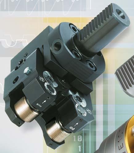
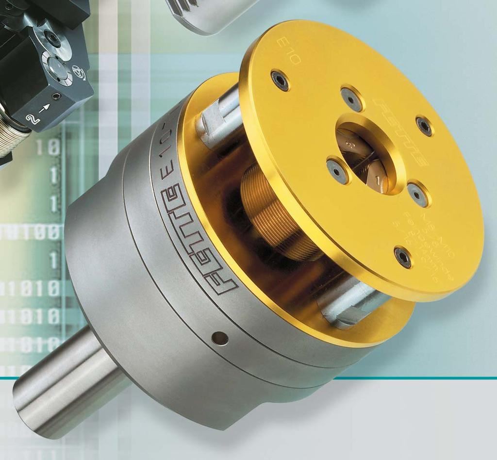
24 Radial-Gewinde-Rollköpfe Typ E und Typ EW Radial thread rolling heads type E and type EW Radial-Gewinde-Rollköpfe der Typ E werden auf der Maschine über dem Werkstück in axialer Richtung in Rollposition gebracht. Mittels einer der beiden Auslösehebel (äußerer, innerer) wird der ausgelöst und der Rollvorgang startet. Nach einer Rollenumdrehung ist das Gewinde geformt und der kann in axialer Richtung zurückgefahren werden. Eine externe Auslösevorrichtung (z. B. durch die Spindel) ist für Rollköpfe dieser Type zwingend erforderlch, wodurch aber die Baulänge dieser Typen relativ kurz gehalten werden kann. Sehen Sie diese Typen bitte in unserem Katalog für Rollwerkzeuge Radial-Gewinde-Rollköpfe der Typ EW benötigen keine externe Auslösevorrichtung. Durch den drehbaren Innenanschlag wird der durch das Werkstück ausgelöst. Das Werkstück wird so lange in axialer Richtung in den eingeführt, bis die interne Auslösung den Rollvorgang startet. Um Relativbewegungen zwischen und Werkstück während des Rollvorgangs zu vermeiden, ist der vordere Teil des s schwimmend gelagert. Sehen Sie diese Typen bitte in unserem Katalog für Rollwerkzeuge Wichtig: Für beide Typen können die gleichen verwendet werden. Beide Typen gibt es in verschiedenen Baugrößen (abhängig von Gewindegröße und Platz auf der Maschine) und verschiedenen Ausführungen (Flanschausführung, Schaftausführungen). Semi- Standard-Ausführungen, wie größere Frontplattenbohrungen, dünnere Frontplatten, und verlängerte Rollenbreiten sind vorgesehen. Sonstige Sonderausführungen sind auf Anfrage machbar. Fette-Radial-Gewinde-Rollköpfe umfassen einen Arbeitsbereich bis Ø 45 mm. Die Aufteilung des Arbeitsbereichs zeigen nachfolgende Tabellen. Für Linksgewinde wird derselbe benutzt wie für Rechtsgewinde, es müssen jedoch spezielle Linksgewinderollen verwendet werden. Die Gewindelänge, einschließlich des Gewindeauslaufs, kann nicht länger als die Rollenbreite sein. Type E radial thread rolling heads are brought into rolling position on the machine over the workpiece in axial direction. The rolling head is released, and the rolling process started, by one of the two triggers (external, internal). The thread has been formed after one rolling rotation of the roll, and the rolling head can be drawn back in axial direction. An external trigger mechanism (e.g. by means of the spindle) is essential for rolling heads of this type, and this keeps the physical length of these types relatively short. Radial thread rolling heads of type EW do not need an external trigger. The workpiece triggers the rolling head by an rotating internal stop. The workpiece is inserted axially into the rolling head until the internal trigger mechanism initiates the rolling procedure. In order to avoid relative movements of the rolling head and the workpiece during the rolling procedure, the front part of the rolling head is mounted on floating bearings. Important: the same thread roll can be used for both types. All of these types are available in different sizes (depending on the thread dimensions and the space on the machine) and in a number of versions (flange version, shank versions). Semi-standard versions, such as larger front plate holes, thinner front plates and increased rolls widths are available. Other special versions can be made on request. Fette radial thread rolling heads cover a working range of up to 45 mm diameter. The way in which this range is divided is shown in the following tables. The same rolling head can be used for left-hand threads as for right-hand threads, but special left-hand thread roll must be used. The thread length, including the thread run-out, cannot be longer than the width of the roller. EW-Titan mit Sk40 EW-Titanium with tapered shank SK40 Thread Rolling D.29
25 Radial-Gewinde-Rollköpfe Typ E und Typ EW Radial thread rolling heads type E and type EW Arbeitsbereiche Capacity ranges zylindrische Gewinde konische Gewinde Straight Threads Taper threads Feingewinde - max. Steigung Typ Regelgewinde Außen-Ø min. Gang / Rollen- Rolling Standard thread Major-Ø Fine thread breite head mm inch mm inch max. pitch Roll width Norm type min. max. min. max. min. TPI mm inch Standard min. max. EW 10 M 8 x 1,25 M 10 x 1, , , DIN 158 M 8 x 1 keg. taper M 14 x 1,5 keg. taper 5 /16 22 /8 16 /8 9 /16 DIN 2999 R 1 /16 28 R 1 /4 19 DIN 858 R 1 /8 28 R 1 /4 19 ANSI B /16 27 NPT(NPTF) 1 /4 18 NPT(NPTF) EW 1 M 10 x 1,5 M 12 x 1, , , DIN 158 M 10 x 1 keg. taper M 18 x 1,5 keg. taper 7 / / /16 /16 DIN R /8 28 R /8 19 DIN 858 R 1 /8 28 R /8 19 ANSI B /8 27 NPT(NPTF) /8 18 NPT(NPTF) EW 16 M 12 x 1,75 M 16 x ,0 1 29, DIN 158 M 12 x 1,25 keg. taper M 22 x 1,5 keg. taper 1 / / /2 /8 DIN R / R /2 14 DIN 858 R 1 /4 19 R 1 /2 14 ANSI B /4 18 NPT(NPTF) 1 /2 14 NPT(NPTF) EW 2 M 16 x 2 M 16 x ,0 12 4,6 1.6 DIN 158 M 16 x 1,5 keg. taper M 0 x 2 keg. taper 5 / / /8 1 /16 DIN 2999 R /8 19 R /4 14 DIN 858 R /8 19 R /4 14 ANSI B /8 18 NPT(NPTF) /4 14 NPT(NPTF) Artikel-Nr. für gängige Rechtsgewinde in Ausführungsart A für die verschiedenen größen sind auf den Seiten R29 R4 angegeben. Durchmesser und Steigungen, die in der Tabelle nicht enthalten sind auf Anfrage. A list of Ident No. for the standard right-hand thread rolls version A is shown for different head sizes, on pages R29 R4. Please inquire dimensions and pitches not shown in attached table individually. D.240

26 Radial-Gewinde-Rollköpfe EW10A00 EW2A00 Radial thread rolling heads EW10A00 EW2A00 EW10A00 EW1A00 EW16A00 EW2A00 D 6 D 5 +0, " D 4 +0,010 0" D 7 L 2 L 6 L 7 L 8 L L 1 = Schaltweg L 1 = Trip lever movement L 2 = Hub L 2 = Stroke D 7 = 4 x am Umfang D 7 = 4 x at the perimeter L 11 L 10 L 1 D 2 D 1 L L 4 -Typ Rolling head type D 1 D 2 min/max 1) D 4 D 5 D 6 D 7 L L 1 ca. max. L 2 L L 4 L 6 L 7 L 8 L 10 L 11 max. Gewicht (kg) Weight (kg) Head Rollen Rolls Gesamt Total Rolling head 1) Im Regelfall D 2min. 1) In general D 2min. EW10A00 EW1A00 EW16A00 EW2A / / / / ,5/ / / / , , ,5 0.18, , , , , , , , , , , , , , , , , , ,5 1,7 2,6 0,4 0,8 1,5,2 6,4 10, 15,2 26,8 Ident No. Ident No. Ident No. Ident No Thread Rolling D.241
27 Ersatzteile für Rollköpfe EW10A00 EW2A00 Spare parts for rolling heads EW10A00 EW2A00 EW10A00 EW1A00 EW16A00 EW2A00 Rolling head Teil Nr. Stück Bennenung Part No. Qty. Part description Ident No. Ident No. Ident No. Ident No. 1 1 Federgehäuse Spring housing 2 1 Getriebeplatte Drive gear plate 1 Deckplatte Cover plate 4 1 Frontplatte Front plate 5 Synchronzahnrad mit DU-Buchse Synchronized gear with bushing 6 1 Mittelzahnrad Center gear 7 Verstellzahnrad Adjusting gear 8 1 Zahnkranz Gear rim 9 Exzenterbolzen Excentric spindle 10 1 äußerer Auslösehebel External trip release lever 11 Distanzbolzen Spacer pin 12 Mitnehmerscheibe Drive plate 1 2 Kupplungsbolzen Clutch pin 15 Laufbuchse Bushing 16 2 Passfeder Fitting key 17 1 Zugfedersatz Tension spring set 18 1 Anschlag Clutch stop 19 Zylinderstift Pin 20 1 Druckfeder, stark Pressure spring, heavy 21 1 Druckfeder, schwach Pressure spring, light 22 Gewinderolle siehe Einzelfall Thread roll individual 2 1 Innerer Auslösehebel Internal trip lever 24 1 Zylinderschraube Cap screw 25 1 DU-Buchse Bushing 26 2 Sechskantmutter Hexagon nut 27 2 Scheibe Washer 28 2 Stiftschraube Stud 29 4 Spannhülse Pin 0 1 Zylinderstift Pin D.242
28 Ersatzteile für Rollköpfe EW10A00 EW2A00 Spare parts for rolling heads EW10A00 EW2A00 EW10A00 EW1A00 EW16A00 EW2A00 Rolling Head Teil Nr. Stück Bennenung Part No. Qty. Part description Ident No. Ident No. Ident No. Ident No. 2 Zylinderschraube Cap screw Zylinderschraube Cap screw 4 1 DU-Buchse Bushing 6 1 Druckstift Pressure pin 49 1 Anschlagbuchse Bushing 50 1 Kugeldruckschraube Ball screw 51 1 Kugeldruckschraube 1) Ball screw 51 1 Laufbuchse 1) Bushing 5 1 Halteleiste Fillet 56 1 Senkschraube Countersunk screw 56 Zylinderschraube Cap screw 57 1 Kontermutter Counter nut 60 1 Mitnehmer Tappet 61 1 Druckplatte 1) Pressure plate 62 Distanzschraube Distance screw 6 4 Zylinderstift Pin 64 8 DU-Buchse Bushing DU-Buchse Bushing 65 Druckfeder Pressure spring 67 1 Druckbolzen Bolt 68 1 Spannschraube Clambing screw Tellerfeder Spring Tellerfeder Spring Tellerfeder Spring 69 8 Tellerfeder Spring Thread Rolling 1) 1) Nicht dargestellt Not shown in the sketch Bei Bestellung von Rollköpfen, Ersatzteilen und gleicher, bereits gelieferter Ausführungen, unbedingt aufsignierte Bezeichnung, Teil Nr. und Ident No. angeben! Important! When ordering rolling head spare parts and thread rolls identical to those already supplied, it is essential to give the Type, size, Part No. and Ident No. D.24


29 Ersatzteile für Rollköpfe EW10A00 EW2A00 Spare parts for rolling heads EW10A00 EW2A D.244
30 en, Ident No. der für zylindrische Werkstück-Rechtsgewinde Ausführung A Thread Sizes, Ident No. for thread rolls for straight right-hand threads Version A Metrisches ISO-Gewinde, DIN 1 Metric ISO thread, DIN 1 -Typen in Ausführungsart Head type and version EW10 EW1 EW16 EW2 Rollenbreite (mm inch) Roll width (mm inch) 19, " 24, " 29, " 4,6 1.62" Rollenausführungsart Roll version A A A A Thread size Ident No. Ident No. Ident No. Ident No. M x 0.5 M.5 x 0.6 M 4 x 0.7 M 4 x 0.5 M 5 x 0.8 M 5 x 0.5 M 6 x 1 M 6 x 0.75 M 6 x 0.5 M 8 x M 8 x M 8 x M 8 x M 10 x M 10 x M 10 x M 10 x M 12 x M 12 x M 12 x M 12 x M 14 x M 14 x M 14 x M 14 x M 15 x M 15 x M 16 x M 16 x M 16 x M 17 x M 18 x M 18 x M 18 x M 20 x M 20 x M 20 x M 22 x M 22 x M 22 x M 24 x M 24 x M 24 x M 25 x M 26 x M 27 x M 27 x M 28 x Thread Rolling Linksgewinde und Ausführungsart B auf Anfrage Left-hand thread rolls and Version B rolls on request D.245
31 en, Ident No. der für zylindrische Werkstück-Rechtsgewinde Ausführung A Thread Sizes, Ident No. for Thread Rolls for straight Right-Hand Threads Version A Metrisches ISO-Gewinde, DIN 1 Metric ISO Thread, DIN 1 -Typen in Ausführungsart Head Type and Version EW10 EW1 EW16 EW2 Rollenbreite (mm inch) Roll width (mm inch) 19, " 24, " 29, " 4,6 1.62" Rollenausführungsart Roll version A A A A Thread Size Ident No. Ident No. Ident No. Ident No. M 0 x M 0 x Unified-Schraubengewinde ANSI B1.1 Unified Thread ANSI B1.1 -Typen in Ausführungsart Head Type and Version EW10 EW1 EW16 EW2 Rollenbreite (mm inch) Roll width (mm inch) 19, " 24, " 29, " 4,6 1.62" Rollenausführungsart Roll version A A A A Thread Size Ident No. Ident No. Ident No. Ident No. 5 /16 24 UNF /16 2 UNEF /8 16 UNC /8 24 UNF /8 2 UNEF /16 14 UNC /16 20 UNF /16 28 UNEF /2 1 UNC D.246
32 en, Ident No. der für zylindrische Werkstück-Rechtsgewinde Ausführung A Thread sizes, Ident No. for thread rolls for straight right-hand threads Version A Unified-Schraubengewinde ANSI B1.1 Unified Thread ANSI B1.1 -Typen in Ausführungsart Head Type and Version EW10 EW1 EW16 EW2 Rollenbreite (mm inch) Roll width (mm inch) 19, " 24, " 29, " 4,6 1.62" Rollenausführungsart Roll version A A A A Thread Size Ident No. Ident No. Ident No. Ident No. 1 /2 20 UNF /2 28 UNEF /16 12 UNC /16 18 UNF /16 24 UNEF /8 11 UNC /8 18 UNF /8 24 UNEF /16 24 UNEF /4 16 UNF /4 20 UNEF /16 20 UNEF /8 14 UNF /8 20 UNEF /16 20 UNEF UNF UNEF /16 18 UNEF /8 12 UNF /8 18 UNEF /16 18 UNEF Thread Rolling D.247
33 en, Ident No. der für zylindrische Werkstück-Rechtsgewinde Ausführung A Thread sizes, Ident No. for thread rolls for straight right-hand threads Version A Unified-Schraubengewinde ANSI B1.1 Unified Thread ANSI B1.1 -Typen in Ausführungsart Head Type and Version EW10 EW1 EW16 EW2 Rollenbreite (mm inch) Roll width (mm inch) 19, " 24, " 29, " 4,6 1.62" Rollenausführungsart Roll version A A A A Thread Size Ident No. Ident No. Ident No. Ident No. 1 /2 20 UNF /2 28 UNEF /16 12 UNC /16 18 UNF /16 24 UNEF /8 11 UNC /8 18 UNF /8 24 UNEF /16 24 UNEF /4 16 UNF /4 20 UNEF /16 20 UNEF /8 14 UNF /8 20 UNEF /16 20 UNEF UNF UNEF /16 18 UNEF /8 12 UNF /8 18 UNEF /16 18 UNEF D.248
34 en, Ident No. der für zylindrische Werkstück-Rechtsgewinde Ausführung A Thread sizes, Ident No. for thread Rolls for straight right-hand threads Version A Whitworth-Gewinde B.S.84 Whitworth thread B.S.84 -Typen in Ausführungsart Head Type and Version EW10 EW1 EW16 EW2 Rollenbreite (mm inch) Roll width (mm inch) 19, " 24, " 29, " 4,6 1.62" Rollenausführungsart Roll version A A A A Thread Size Ident No. Ident No. Ident No. Ident No. 5 /16 18 BSW /16 22 BSF /8 16 BSW /8 20 BSF /16 14 BSW /16 18 BSF /2 12 BSW /2 16 BSF /16 12 BSW /16 16 BSF /8 11 BSW /8 14 BSF /16 11 BSW /16 14 BSF /4 10 BSW /4 12 BSF /16 12 BSF /8 9 BSW 7 /8 11 BSF Whitworth-Rohrgewinde, zylindrisch DIN ISO 228 Whitworth pipe thread, parallel DIN ISO 228 -Typen in Ausführungsart Head Type and Version EW10 EW1 EW16 EW2 Rollenbreite (mm inch) Roll width (mm inch) 19, " 24, " 29, " 4,6 1.62" Rollenausführungsart Roll version A A A A Thread Size Ident No. Ident No. Ident No. Ident No. G 1 / G 1 / G / G 1 / G 5 / G / Thread Rolling This is only a small excerpt from the FETTE catalogue Rolling systems. Please request the ask for program. D.249
35 en, Ident No. der für kegelige Werkstück-Rechtsgewinde Ausführung A Thread Sizes, Ident No. for thread rolls for parallel right-hand threads Version A Whitworth-Rohrgewinde, kegelig, DIN 2999 Whitworth pipe thread, tapered, DIN Typen in Ausführungsart Head type and version EW10 EW1 EW16 EW2 Rollenausführungsart Roll version A A A A Rollen- Rollen- Rollen- Rollenbreite breite breite breite Roll Roll Roll Roll width width width width Thread Size Ident No. mm inch Ident No. mm inch Ident No. mm inch Ident No. mm inch R 1 / R 1 / R 1 / R / R 1 / R / Whitworth-Rohrgewinde, kegelig, DIN 858 Regelgewinde Whitworth pipe thread, tapered, DIN 858 -Typen in Ausführungsart Head type and version EW10 EW1 EW16 EW2 Rollenausführungsart Roll version A A A A Rollen- Rollen- Rollen- Rollenbreite breite breite breite Roll Roll Roll Roll width width width width Thread Size Ident No. mm inch Ident No. mm inch Ident No. mm inch Ident No. mm inch R 1 / R 1 / R / R 1 / R / Dies ist nur ein kleiner Auszug aus aus dem FETTE-Katalog Rollsysteme. Bitte fordern Sie das Gesamtprogramm an. This is only only a small excerpt from the FETTE catalogue Rolling systems. Please ask for the standard program. D.250
36 Thread rolls Für jede ist ein Satz (22) 1) nötig. Ein Satz besteht aus drei unterschiedlichen. Sie sind mit den Nummern 1, 2 und gekennzeichnet. Die Lage der im ist vorgeschrieben. Die Rollen sind in der Reihenfolge 1 2 im Uhrzeigersinn, gegen Vorderkante Frontplatte gesehen, einzubauen. Dieses gilt für Rechtsund Linksgewinde. Es ist wichtig, dass ein zusammengehöriger Satz eingebaut wird. Die Drehrichtung der Maschinenspindel bestimmt beim die Ausführungsart A oder B. Die (22) werden ebenfalls danach unterschieden. Es dürfen beispielsweise (22) mit der Bezeichnung A nur in die Rollköpfe der Ausführung A eingebaut werden. Die Bezeichnung der (22) besteht aus der Gewindebezeichnung, der größe, der Ausführungsart, der Rollennummer und der Artikel-Nr. One set of thread rolls (#22) 1) is required for each size of thread. A set consists of three different rolls. They are marked 1, 2 and. The location of the rolls in the rolling attachment is specified. The rolls must be assembled in sequence 1 2 clockwise. It is important that a matching set be assembled. The direction of rotation of the machine spindle determines whether rolling head A or B is to be used. This also determines the type of thread rolls (#22) to be used. For example, thread rolls (#22) marked A can only be assembled in a version A rolling head. The identification marking of the thread rolls (#22) consists of the thread identification, the size of rolling head, the type of rolling head and the roll number. Beispiel für M 12 x 1,75 in typen E 16 A 00, E 16 A 01, E 16 A 02 Example for M 12 x 1.75 on rolling head types E 16 A 00, E 16 A 01, E 16 A 02 Gewinde-Code-Nr. E A 29 Thread roll code number E A 29 -Typ Rollenbreite Rolling head type Roll width größe Ausführungsart Rolling head size Version lfd. Gewinde-Nr. Serial code number Arbeitsbeispiel: M 12 x 1,75 -Typ E 16 A 00 (E 16 A 01, E 16 A 02) Bestellbeispiel: 1 Satz für Gewinde M 12 x 1,75 für -Typ E 16 A 00 (E 16 A 01, E 16 A 02) Artikel-Nr (siehe Seite D.245) (Artikel-Nr. nur, falls bekannt) Example: Thread size M 12 x 1.75 Rolling head type E 16 A 00 (E 16 A 01, E 16 A 02) Ordering example: 1 set thread rolls for thread M 12 x 1.75 for head type E 16 A 00 (E 16 A 01, E 16 A 02) Ident No (see Page D.245) (Ident No. only if known) Hinweis: Grundsätzlich wird jede Rolle für zylindrische Gewinde im Regelfall mit voller Rollenbreite geliefert. Der Gewindeauslauf der Rolle beträgt pro Seite 1 x Steigung. Ansichtsrichtung beim Rolleneinbau View, when assembling the rolls Note: In general, each roll for parallel thread is delivered with full length. The lead of the roll on each side is approx. 1 x pitch. Einbaufolge: 1 2 im Uhrzeigersinn in Ansichtsrichtung für Rechts- und Linksgewinde Sequence of assembly: 1 2 clockwise, when viewed from front, for right-hand and left-hand threads 1 2 Thread Rolling 1) Diese Zahlen entsprechen den Ersatzteil-Nr. auf den Seiten Standardkatalog 261, 265, 269, 271, 27, 281, ) These figures correspond to the part numbers on the list of spare parts (see standard catalogue 261, 265, 269, 271, 27, 281, 285. Dies ist nur ein kleiner Auszug ausdem FETTE-Katalog Rollsysteme. Bitte fordern Sie das Gesamtprogramm an. D.251


37 Tangential-Gewinde-Rollköpfe Tangential Thread Rolling Heads A.D.252

38 Tangential-Rollköpfe T120F, T160F, T220F, T50F Tangential rolling attachments T120F, T160F, T220F, T50F Für Linksgewinde wird derselbe benutzt wie für Rechtsgewinde. Die müssen für Linksgewinde ausgelegt sein. For left-hand threads, the same rolling attachment can be used as for right-hand threads. Left-hand threads require left-hand rolls. L Spitzenhöhe Center height Nutaufnahme Key way fitting Längenmaß Lenght dimension b 1 D max = max. zulässiger Werkstückbund-Ø, siehe Internet. max. shoulder diameter (Internet or Fette representative) A v = Arbeitsvorschub, siehe Internet Operating feed (manual, Internet or Fette representative) AV L 1 L 2 D max. d max. h 2 h 1 h 2 b b 2 L 4 Die Angaben für den halter entsprechen einem Halter für Querschlittenaufnahme. Baumaße für andere halteraufnahmen sind der jeweiligen Drehmaschine angepasst. Dimensions above refer to cross slide mounted holder. Dimensions for other tool holder are adapted to the respective machine. Baumaße Dimensions -Typ Rolling Attachment mm inch b 1 b 2 b L 1 L 2 L L 4 h 1 h 2 max. min/max. min. min/max. d max. Gewicht (kg lb) Weight (kg lb) Rolling Attachment -Halter Rolling Attachment Holder Rollen (1 Satz = 2 Stück) Thread Roll (1 Set = 2 Pieces) Gesamt Total T120F T160F T220F T50F , , , , , ,2/27,6 0.91/ ,2/, /1.15 7,2/46, / ,2/7, 2.409/ , , , ,5/ / / / /74, / /105, / , , , , , , , , 2.86, , , ,7.74 4, ,0.5 0, , , ,6 2. 1,57.45, , , Ident No. Ident No. Ident No. Ident No Thread Rolling D.25
39 Ersatzteile für Rollköpfe T120F, T160F, T220F, T50F Spare parts for rolling attachments T120F, T160F, T220F, T50F T120F T160F T220F T50F Rolling Head Teil Nr. Stück Bennenung Part No. Qty. Part description Ident No. Ident No. Ident No. Ident No. 1 1) 1 Scharnier-Oberteil Upper arm 2 1) 1 Scharnier-Unterteil mit Steckkerbstift Lower arm with pin 2 Achse Shaft 4 1 Buchse Center shaft 5 1 Buchse mit Steckkerbstift Bushing 6 1 Buchse Bushing 7 2 Lagerbuchse Bearing Bushing 8 2 Ritzel Pinion 9 2 Zugfeder Tension spring 10 2 Zahnrad mit DU-Buchse Gear with bushing 11 1 Zahnradsatz mit Spiralfeder (Teile 11, 12, 16) Gear with coil spring (see part no. 11, 12, 16) 1 2 Buchse Bushing 15 2 Scheibe Washer 16 1 Spiralfeder (s. lfd. Nr. 11) Balance spring (see part no. 11) 18 2 Gewinderolle siehe Einzelfall Thread roll individual 21 2 Trichter-Schmiernippel Grease nipple 24 2 Zylinderschraube Cap screw 25 2 Gewindestift Set screw 26 4 Steckkerbstift bzw. Spannhülse Straight pin resp. clamping sleeve 27 1 Gewindestift Set screw 28 2 Zylinderschraube Locking screw 29 L 1 Verstellachse Linksgewinde Spindle nut (LH) 29 R 1 Verstellachse Rechtsgewinde Spindle nut (RH) 0 1 Spindel Spindle 2 Steckkerbstift (s. lfd. Nr. 2 und 5) DIN 1474 pin (see part no. 2, 5) 4 2 Sicherungsring Centering ring 5 2 Sicherungsscheibe Lock washer 6 1 Prüflehre Reference gage D.254
40 Ersatzteile für Rollköpfe T120F, T160F, T220F, T50F Spare parts for rolling attachments T120F, T160F, T220F, T50F T120F T160F T220F T50F Rolling Head Teil Nr. Stück Bennenung Part No. Qty. Part description Ident No. Ident No. Ident No. Ident No. 7 2 Gewindestift Set screw 1 halter komplett abhängig vom Maschinentyp Attachment Holder complete depending on type of machine Grundkörper siehe Einzelfall Basic housing individual Bolzen siehe Einzelfall Bolt individual Zum Beispiel: Schaft VDI siehe Einzelfall For Example: VDI-shank individual Federblechhalter komplett Spring clip holder complete Gewindestift Set screw Gewindestift Set screw 1-17 Zylinderschrauben siehe Einzelfall Cap screw individual 2 1 Einstelllehre siehe Einzelfall Setting gauge individual 1) 1) Nur paarweise liefer- und einsetzbar. Be available only as a pair. Thread Rolling Bei Bestellung von Rollköpfen, Ersatzteilen, haltern und gleicher, bereits gelieferter Ausführungen, unbedingt aufsignierte Bezeichnung und Ident No. angeben! When ordering rolling attachment, spare parts, rolling attachment holders, setting gauges and thread rolls of the same type as previously supplied, it is absolutely necessary to state the marking on this attachment, size and Ident no. D.255


41 Ersatzteile für Rollköpfe T120F, T160F, T220F, T50F Spare parts for rolling attachments T120F, T160F, T220F, T50F R L D.256
42 en, Artikel-Nr. der für zylindrische Werkstück-Rechtsgewinde, Ausführung A Thread sizes, Ident No. for thread rolls with right-hand threads Version Metrisches ISO-Gewinde DIN 1 Metric ISO Threads DIN 1 T120F Rolling Head Rollenbreiten ,5 Roll width 0.26" 0.15" 0.94" 0.472" 0.610" Thread size Ident No. Ident No. Ident No. Ident No. Ident No. Z M 2 x 0,4* M 2,2 x 0,45* M 2,5 x 0,45* M x 0,5* M,5 x 0,6* M,5 x 0, M 4 x 0,7* M 4 x 0, M 4,5 x 0,75* M 4,5 x 0, M 5 x 0,8* M 5 x 0, M 5,5 x 0, M 5,5 x 0, M 6 x 1* M 6 x 0, M 6 x 0, M 7 x M 7 x 0, M 7 x 0, M 8 x 1,25* M 8 x M 8 x 0, M 8 x 0, M 9 x 1, M 9 x M 9 x 0, M 9 x 0, M 10 x 1,5* M 10 x 1, M 10 x M 10 x 0, M 10 x 0, M 11 x 1, M 11 x M 11 x 0, M 11 x 0, M 12 x 1, M 12 x 1, M 12 x M 12 x 0,75* M 12 x 0, M 1 x 1, M 1 x M 1 x 0, M 1 x 0, M 14 x 1, M 14 x 1, M 14 x M 14 x 0, M 14 x 0, Thread Rolling * Standardgewinde (DIN 1 Teil 1) * Standard thread (to DIN 1 part 1) D.257
43 en, Artikel-Nr. der für zylindrische Werkstück-Rechtsgewinde, Ausführung A Thread sizes, Ident No. for thread rolls with right-hand threads Version A Metrisches ISO-Gewinde DIN 1 Metric ISO Threads DIN 1 T160F Rolling Head Rollenbreiten ,5 Roll width 0.26" 0.15" 0.94" 0.472" 0.551" 0.60" 0.728" Thread size Ident No. Ident No. Ident No. Ident No. Ident No. Ident No. Ident No. Z M 2 x 0,4* M 2,2 x 0,45* M 2,5 x 0,45* M x 0,5* M,5 x 0,6* M,5 x 0, M 4 x 0,7* M 4 x 0, M 4,5 x 0,75* M 4,5 x 0, M 5 x 0,8* M 5 x 0, M 5,5 x 0, M 5,5 x 0, M 6 x 1* M 6 x 0, M 6 x 0, M 7 x M 7 x 0, M 7 x 0, M 8 x 1,25* M 8 x M 8 x 0, M 8 x 0, M 9 x 1, M 9 x M 9 x 0, M 9 x 0, M 10 x 1,5* M 10 x 1, M 10 x M 10 x 0, M 10 x 0, M 11 x 1, M 11 x M 11 x 0, M 11 x 0, M 12 x 1, M 12 x 1, M 12 x 1, M 12 x M 12 x 0,75* M 12 x 0, M 1 x 1, M 1 x M 1 x 0, M 1 x 0, M 14 x 1, M 14 x 1, M 14 x M 14 x 0, M 14 x 0, * Standardgewinde (DIN 1 Teil 1) * Standard thread (to DIN 1 part 1) D.258
44 en, Artikel-Nr. der für zylindrische Werkstück-Rechtsgewinde, Ausführung A Thread sizes, Ident No. for thread rolls with right-hand threads Version A Metrisches ISO-Gewinde DIN 1 Metric ISO Threads DIN 1 T160F Rolling Head Rollenbreiten ,5 Roll width 0.26" 0.15" 0.94" 0.472" 0.551" 0.60" 0.728" Thread size Ident No. Ident No. Ident No. Ident No. Ident No. Ident No. Ident No. Z M 15 x 1, M 15 x M 15 x 0, M 15 x 0, M 16 x 1, M 16 x M 16 x 0, M 16 x 0, M 17 x 1, M 17 x Metrisches ISO-Gewinde DIN 1 Metric ISO Threads DIN 1 T220F Rolling Head Rollenbreiten Roll width 0.15" 0.94" 0.472" 0.551" 0.60" 0.709" 0.787" 0.866" 0.945" 1.024" Thread size Ident No. Ident No. Ident No. Ident No. Ident No. Ident No. Ident No. Ident No. Ident No. Ident No. Z M 2 x 0,4* M 2,2 x 0,45* M 2,5 x 0,45* M x 0,5* M,5 x 0,6* M,5 x 0, M 4 x 0,7* M 4 x 0, M 4,5 x 0,75* M 4,5 x 0, M 5 x 0,8* M 5 x 0, M 5,5 x 0, M 5,5 x 0, M 6 x 1* M 6 x 0, M 6 x 0, M 7 x M 7 x 0, M 7 x 0, M 8 x 1,25* M 8 x M 8 x 0, M 8 x 0, M 9 x 1, M 9 x M 9 x 0, M 9 x 0, M 10 x 1,5* M 10 x 1, M 10 x * Standardgewinde (DIN 1 Teil 1) * Standard thread (to DIN 1 part 1) D.259 Thread Rolling
45 en, Artikel-Nr. der für zylindrische Werkstück-Rechtsgewinde, Ausführung A Thread sizes, Ident No. for thread rolls with right-hand threads Version A Metrisches ISO-Gewinde DIN 1 Metric ISO Threads DIN 1 T220F Rolling Head Rollenbreiten Roll width 0.15" 0.94" 0.472" 0.551" 0.60" 0.709" 0.787" 0.866" 0.945" 1.024" Thread size Ident No. Ident No. Ident No. Ident No. Ident No. Ident No. Ident No. Ident No. Ident No. Ident No. Z M 10 x 0,75 M 10 x 0,5 M 11 x 1,5 M 11 x 1 M 11 x 0,75 M 11 x 0,5 M 12 x 1,75* M 12 x 1,5 M 12 x 1,25 M 12 x 1 M 12 x 0,75 M 12 x 0,5 M 1 x 1,5 M 1 x 1 M 1 x 0,75 M 1 x 0,5 M 14 x 2* M 14 x 1,5 M 14 x 1,25 M 14 x 1 M 14 x 0,75 M 14 x 0,5 M 15 x 1,5 M 15 x 1 M 15 x 0,75 M 15 x 0,5 M 16 x 2* M 16 x 1,5 M 16 x 1 M 16 x 0,75 M 16 x 0,5 M 17 x 2 M 17 x 1,5 M 17 x 1 M 17 x 0,75 M 17 x 0,5 M 18 x 2,5* M 18 x 2 M 18 x 1,5 M 18 x 1 M 18 x 0,75 M 18 x 0,5 M 19 x 2 M 19 x 1,5 M 19 x 1 M 19 x 0,75 M 19 x 0,5 M 20 x 2,5* M 20 x 2 M 20 x 1,5 M 20 x 1 M 20 x 0, * Standardgewinde (DIN 1 Teil 1) * Standard thread (to DIN 1 part 1) D.260
46 en, Artikel-Nr. der für zylindrische Werkstück-Rechtsgewinde, Ausführung A Thread sizes, Ident No. for thread rolls with right-hand threads Version A Metrisches ISO-Gewinde DIN 1 Metric ISO Threads DIN 1 T220F Rolling Head Rollenbreiten Roll width 0.15" 0.94" 0.472" 0.551" 0.60" 0.709" 0.787" 0.866" 0.945" 1.024" Thread size Ident No. Ident No. Ident No. Ident No. Ident No. Ident No. Ident No. Ident No. Ident No. Ident No. Z M 20 x 0, M 21 x M 21 x 1, M 21 x M 21 x 0, M 21 x 0, M 22 x 2,5* M 22 x M 22 x 1, M 22 x M 22 x 0, M 22 x 0, M 2 x M 2 x 1, M 2 x M 2 x 0, M 2 x 0, M 24 x M 24 x 1, M 24 x M 24 x 0, M 24 x 0, M 25 x M 25 x 1, M 25 x M 25 x 0, M 25 x 0, M 26 x M 26 x 1, M 26 x M 26 x 0, M 26 x 0, M 27 x M 27 x 1, M 27 x M 27 x 0, M 27 x 0, M 28 x M 28 x 1, M 28 x M 28 x 0, M 28 x 0, M 0 x M 0 x 1, M 0 x M 0 x 0, M 0 x 0, M 2 x M 2 x 1, M 2 x M 2 x 0, M 2 x 0, * Standardgewinde (DIN 1 Teil 1) * Standard thread (to DIN 1 part 1) D.261 Thread Rolling
47 en, Artikel-Nr. der für zylindrische Werkstück-Rechtsgewinde, Ausführung A Thread sizes, Ident No. for thread rolls with right-hand threads Version A Metrisches ISO-Gewinde DIN 1 Metric ISO Threads DIN 1 T220F Rolling Head Rollenbreiten Roll width 0.15" 0.94" 0.472" 0.551" 0.60" 0.709" 0.787" 0.866" 0.945" 1.024" Thread size Ident No. Ident No. Ident No. Ident No. Ident No. Ident No. Ident No. Ident No. Ident No. Ident No. Z M x M x 1, M x M x 0, M x 0, M 4 x M 4 x 1, M 4 x M 4 x 0, M 4 x 0, M 5 x M 5 x 1, M 5 x M 5 x 0, M 5 x 0, M 6 x M 6 x 1, M 6 x M 6 x 0, M 6 x 0, M 8 x M 8 x 1, M 8 x Metrisches ISO-Gewinde DIN 1 Metric ISO Threads DIN 1 T50F Rolling Head Rollenbreiten Roll width 0.15" 0.94" 0.472" 0.551" 0.60" 0.709" 0.787" 0.866" Thread size Ident No. Ident No. Ident No. Ident No. Ident No. Ident No. Ident No. Ident No. M 5 x 0,8* M 5 x 0, M 5,5 x 0, M 5,5 x 0, M 6 x 1* M 6 x 0, M 6 x 0, M 7 x M 7 x 0, M 7 x 0, M 8 x 1,25* M 8 x M 8 x 0, M 8 x 0, M 9 x 1, M 9 x M 9 x 0, M 9 x 0, * Standardgewinde (DIN 1 Teil 1) * Standard thread (to DIN 1 part 1) D.262
48 en, Artikel-Nr. der für zylindrische Werkstück-Rechtsgewinde, Ausführung A Thread sizes, Ident No. for thread rolls with right-hand threads Version A Metrisches ISO-Gewinde DIN 1 Metric ISO Threads DIN 1 T50F Rolling Head Rollenbreiten Roll width 0.15" 0.94" 0.472" 0.551" 0.60" 0.709" 0.787" 0.866" Thread size Ident No. Ident No. Ident No. Ident No. Ident No. Ident No. Ident No. Ident No. M 10 x 1,5* M 10 x 1, M 10 x M 10 x 0, M 10 x 0, M 11 x 1, M 11 x M 11 x 0, M 11 x 0, M 12 x 1,75* M 12 x 1, M 12 x 1, M 12 x M 12 x 0, M 12 x 0, M 1 x 1, M 1 x M 1 x 0, M 1 x 0, M 14 x 2* M 14 x 1, M 14 x 1, M 14 x M 14 x 0, M 14 x 0, M 15 x 1, M 15 x M 15 x 0, M 15 x 0, M 16 x 2* M 16 x 1, M 16 x M 16 x 0, M 16 x 0, M 17 x M 17 x 1, M 17 x M 17 x 0, M 17 x 0, M 18 x 2,5* M 18 x M 18 x 1, M 18 x M 18 x 0, M 18 x 0, M 19 x M 19 x 1, M 19 x M 19 x 0, M 19 x 0, M 20 x 2,5* M 20 x * Standardgewinde (DIN 1 Teil 1) * Standard thread (to DIN 1 part 1) D.26 Thread Rolling
49 en, Artikel-Nr. der für zylindrische Werkstück-Rechtsgewinde, Ausführung A Thread sizes, Ident No. for thread rolls with right-hand threads Version A Metrisches ISO-Gewinde DIN 1 Metric ISO Threads DIN 1 T50F Rolling Head Rollenbreiten Roll width 0.15" 0.94" 0.472" 0.551" 0.60" 0.709" 0.787" 0.866" Thread size Ident No. Ident No. Ident No. Ident No. Ident No. Ident No. Ident No. Ident No. M 20 x 1, M 20 x M 20 x 0, M 20 x 0, M 21 x M 21 x 1, M 21 x M 21 x 0, M 21 x 0, M 22 x 2,5* M 22 x M 22 x 1, M 22 x M 22 x 0, M 22 x 0, M 2 x M 2 x 1, M 2 x M 2 x 0, M 2 x 0, M 24 x * M 24 x M 24 x 1, M 24 x M 24 x 0, M 24 x 0, M 25 x M 25 x 1, M 25 x M 25 x 0, M 25 x 0, M 26 x M 26 x 1, M 26 x M 26 x 0, M 26 x 0, M 27 x * M 27 x M 27 x 1, M 27 x M 27 x 0, M 27 x 0, M 28 x M 28 x M 28 x 1, M 28 x M 28 x 0, M 28 x 0, M 0 x M 0 x M 0 x 1, M 0 x * Standardgewinde (DIN 1 Teil 1) * Standard thread (to DIN 1 part 1) D.264
50 en, Artikel-Nr. der für zylindrische Werkstück-Rechtsgewinde, Ausführung A Thread sizes, Ident No. for Thread Rolls with Right-Hand Threads Version A Metrisches ISO-Gewinde DIN 1 Metric ISO Threads DIN 1 T50F Rolling Head Rollenbreiten Roll width 0.15" 0.94" 0.472" 0.551" 0.60" 0.709" 0.787" 0.866" Thread size Ident No. Ident No. Ident No. Ident No. Ident No. Ident No. Ident No. Ident No. M 0 x 0, M 0 x 0, M 2 x M 2 x M 2 x 1, M 2 x M 2 x 0, M 2 x 0, M x M x M x 1, M x M x 0, M x 0, M 4 x M 4 x M 4 x 1, M 4 x M 4 x 0, M 4 x 0, M 5 x M 5 x M 5 x 1, M 5 x M 5 x 0, M 5 x 0, M 6 x M 6 x M 6 x 1, M 6 x M 6 x 0, M 6 x 0, M 8 x M 8 x M 8 x 1, M 8 x M 8 x 0, M 8 x 0, M 9 x M 9 x M 9 x 1, M 9 x M 9 x 0, M 9 x 0, M 40 x M 40 x M 40 x 1, M 40 x M 40 x 0, M 40 x 0, M 42 x M 42 x M 42 x 1, M 42 x D.265 Thread Rolling
51 en, Artikel-Nr. der für zylindrische Werkstück-Rechtsgewinde, Ausführung A Thread sizes, Ident No. for thread rolls with right-hand threads Version A Metrisches ISO-Gewinde DIN 1 Metric ISO Threads DIN 1 T50F Rolling Head Rollenbreiten Roll width 0.15" 0.94" 0.472" 0.551" 0.60" 0.709" 0.787" 0.866" Thread size Ident No. Ident No. Ident No. Ident No. Ident No. Ident No. Ident No. Ident No. M 42 x 0, M 42 x 0, M 45 x M 45 x M 45 x 1, M 45 x M 45 x 0, M 45 x 0, M 48 x M 48 x M 48 x 1, M 48 x M 48 x 0, M 48 x 0, M 50 x M 50 x M 50 x 1, M 50 x M 50 x 0, M 50 x 0, M 52 x M 52 x M 52 x 1, M 52 x M 52 x 0, M 52 x 0, Rollenbreiten Roll width 0.945" 1.024" 1.102" 1.181" 1.26" 1.9" 1.417" Thread size Ident No. Ident No. Ident No. Ident No. Ident No. Ident No. Ident No. M 5 x 0,8* M 5 x 0,5 M 5,5 x 0,75 M 5,5 x 0,5 M 6 x 1* M 6 x 0,75 M 6 x 0,5 M 7 x 1 M 7 x 0,75 M 7 x 0,5 M 8 x 1,25* M 8 x 1 M 8 x 0,75 M 8 x 0,5 M 9 x 1,25 M 9 x 1 M 9 x 0,75 M 9 x 0,5 M 10 x 1,5* M 10 x 1,25 M 10 x 1 D * Standardgewinde (DIN 1 Teil 1) * Standard thread (to DIN 1 part 1)
52 en, Artikel-Nr. der für zylindrische Werkstück-Rechtsgewinde, Ausführung A Thread sizes, Ident No. for thread rolls with right-hand threads Version A Metrisches ISO-Gewinde DIN 1 Metric ISO Threads DIN 1 T50F Rolling Head Rollenbreiten Roll width 0.945" 1.024" 1.102" 1.181" 1.26" 1.9" 1.417" Thread size Ident No. Ident No. Ident No. Ident No. Ident No. Ident No. Ident No. M 10 x 0, M 10 x 0, M 11 x 1, M 11 x M 11 x 0, M 11 x 0, M 12 x 1,75* M 12 x 1, M 12 x 1, M 12 x M 12 x 0, M 12 x 0, M 1 x 1, M 1 x M 1 x 0, M 1 x 0, M 14 x 2* M 14 x 1, M 14 x 1, M 14 x M 14 x 0, M 14 x 0, M 15 x 1, M 15 x M 15 x 0, M 15 x 0, M 16 x 2* M 16 x 1, M 16 x M 16 x 0, M 16 x 0, M 17 x M 17 x 1, M 17 x M 17 x 0, M 17 x 0, M 18 x 2,5* M 18 x M 18 x 1, M 18 x M 18 x 0, M 18 x 0, M 19 x M 19 x 1, M 19 x M 19 x 0, M 19 x 0, M 20 x 2,5* M 20 x M 20 x 1, M 20 x M 20 x 0, * Standardgewinde (DIN 1 Teil 1) * Standard thread (to DIN 1 part 1) D.267 Thread Rolling
53 en, Artikel-Nr. der für zylindrische Werkstück-Rechtsgewinde, Ausführung A Thread sizes, Ident No. for thread rolls with right-hand threads Version A Metrisches ISO-Gewinde DIN 1 Metric ISO Threads DIN 1 T50F Rolling Head Rollenbreiten Roll width 0.945" 1.024" 1.102" 1.181" 1.26" 1.9" 1.417" Thread size Ident No. Ident No. Ident No. Ident No. Ident No. Ident No. Ident No. M 20 x 0, M 21 x M 21 x 1, M 21 x M 21 x 0, M 21 x 0, M 22 x 2,5* M 22 x M 22 x 1, M 22 x M 22 x 0, M 22 x 0, M 2 x M 2 x 1, M 2 x M 2 x 0, M 2 x 0, M 24 x * M 24 x M 24 x 1, M 24 x M 24 x 0, M 24 x 0, M 25 x M 25 x 1, M 25 x M 25 x 0, M 25 x 0, M 26 x M 26 x 1, M 26 x M 26 x 0, M 26 x 0, M 27 x * M 27 x M 27 x 1, M 27 x M 27 x 0, M 27 x 0, M 28 x M 28 x M 28 x 1, M 28 x M 28 x 0, M 28 x 0, M 0 x M 0 x M 0 x 1, M 0 x M 0 x 0, M 0 x 0, M 2 x * Standardgewinde (DIN 1 Teil 1) * Standard thread (to DIN 1 part 1) D.268
54 en, Artikel-Nr. der für zylindrische Werkstück-Rechtsgewinde, Ausführung A Thread sizes, Ident No. for thread rolls with right-hand threads Version A Metrisches ISO-Gewinde DIN 1 Metric ISO Threads DIN 1 T50F Rolling Head Rollenbreiten Roll width 0.945" 1.024" 1.102" 1.181" 1.26" 1.9" 1.417" Thread size Ident No. Ident No. Ident No. Ident No. Ident No. Ident No. Ident No. M 2 x M 2 x 1, M 2 x M 2 x 0, M 2 x 0, M x M x M x 1, M x M x 0, M x 0, M 4 x M 4 x M 4 x 1, M 4 x M 4 x 0, M 4 x 0, M 5 x M 5 x M 5 x 1, M 5 x M 5 x 0, M 5 x 0, M 6 x M 6 x M 6 x 1, M 6 x M 6 x 0, M 6 x 0, M 8 x M 8 x M 8 x 1, M 8 x M 8 x 0, M 8 x 0, M 9 x M 9 x M 9 x 1, M 9 x M 9 x 0, M 9 x 0, M 40 x M 40 x M 40 x 1, M 40 x M 40 x 0, M 40 x 0, M 42 x M 42 x M 42 x 1, M 42 x M 42 x 0, M 42 x 0, M 45 x D.269 Thread Rolling
55 en, Artikel-Nr. der für zylindrische Werkstück-Rechtsgewinde, Ausführung A Thread sizes, Ident No. for thread rolls with right-hand threads Version A Metrisches ISO-Gewinde DIN 1 Metric ISO Threads DIN 1 T50F Rolling Head Rollenbreiten Roll width 0.945" 1.024" 1.102" 1.181" 1.26" 1.9" 1.417" Thread size Ident No. Ident No. Ident No. Ident No. Ident No. Ident No. Ident No. M 45 x M 45 x 1, M 45 x M 45 x 0, M 45 x 0, M 48 x M 48 x M 48 x 1, M 48 x M 48 x 0, M 48 x 0, M 50 x M 50 x M 50 x 1, M 50 x M 50 x 0, M 50 x 0, M 52 x M 52 x M 52 x 1, M 52 x M 52 x 0, M 52 x 0, D.270
56 en, Artikel-Nr. der für zylindrische Werkstück-Rechtsgewinde, Ausführung A Thread sizes, Ident No. for thread rolls with right-hand threads Version A Unified-Gewinde ANSI B1.1 Unified Screw Thread ANSI B1.1 T120F Rolling Head Rollenbreiten ,5 Roll width 0.26" 0.15" 0.94" 0.472" 0.610" Thread size Ident No. Ident No. Ident No. Ident No. Ident No. Z 2 56 UNC UNF UNC UNF UNC UNF UNC UNF UNC UNF UNC UNF UNC UNF UNC UNF UNEF /4 20 UNC /4 28 UNF /4 2 UNEF /16 18 UNC /16 20 UN /16 24 UNF /16 28 UN /16 2 UNEF /8 16 UNC /8 20 UN /8 24 UNF /8 28 UN /8 2 UNEF /16 16 UN /16 20 UNF /16 28 UNEF /16 2 UN /2 16 UN /2 20 UNF /2 28 UNEF /2 2 UN /16 16 UN /16 18 UNF /16 20 UN /16 24 UNEF /16 28 UN /16 2 UN Thread Rolling D.271
57 en, Artikel-Nr. der für zylindrische Werkstück-Rechtsgewinde, Ausführung A Thread sizes, Ident No. for thread rolls with right-hand threads Version A Unified-Gewinde ANSI B1.1 Unified Screw Thread ANSI B1.1 T160F Rolling Head Rollenbreiten ,5 Roll width 0.26" 0.15" 0.94" 0.472" 0.551" 0.60" 0.728" Thread size Ident No. Ident No. Ident No. Ident No. Ident No. Ident No. Ident No. Z 2 56 UNC UNF UNC UNF UNC UNF UNC UNF UNC UNF UNC UNF UNC UNF UNC UNF UNEF /4 20 UNC /4 28 UNF /4 2 UNEF /16 18 UNC /16 20 UN /16 24 UNF /16 28 UN /16 2 UNEF /8 16 UNC /8 20 UN /8 24 UNF /8 28 UN /8 2 UNEF /16 16 UN /16 20 UNF /16 28 UNEF /16 2 UN /2 16 UN /2 20 UNF /2 28 UNEF /2 2 UN /16 16 UN /16 18 UNF /16 20 UN /16 24 UNEF /16 28 UN /16 2 UN /8 16 UN /8 18 UNF /8 20 UN /8 24 UNEF /8 28 UN /8 2 UN D.272
58 en, Artikel-Nr. der für zylindrische Werkstück-Rechtsgewinde, Ausführung A Thread sizes, Ident No. for thread rolls with right-hand threads Version A Unified-Gewinde ANSI B1.1 Unified Screw Thread ANSI B1.1 T220F Rolling Head Rollenbreiten Roll width 0.15" 0.94" 0.472" 0.551" 0.60" 0.709" 0.787" 0.866" 0.945" 1.024" Thread size Ident No. Ident No. Ident No. Ident No. Ident No. Ident No. Ident No. Ident No. Ident No. Ident No. Z 2 56 UNC UNF UNC UNF UNC UNF UNC UNF UNC UNF UNC UNF UNC UNF UNC UNF UNEF /4 20 UNC /4 28 UNF /4 2 UNEF /16 18 UNC /16 20 UN /16 24 UNF /16 28 UN /16 2 UNEF /8 16 UNC /8 20 UN /8 24 UNF /8 28 UN /8 2 UNEF /16 14 UNC /16 16 UN /16 20 UNF /16 28 UNEF /16 2 UN /2 1 UNC /2 16 UN /2 20 UNF /2 28 UNEF /2 2 UN /16 12 UNC /16 16 UN /16 18 UNF /16 20 UN /16 24 UNEF /16 28 UN /16 2 UN /8 11 UNC /8 12 UN /8 16UN /8 18 UNF /8 20 UN /8 24 UNEF /8 28 UN D.27 Thread Rolling
59 en, Artikel-Nr. der für zylindrische Werkstück-Rechtsgewinde, Ausführung A Thread sizes, Ident No. for thread rolls with right-hand threads Version A Unified-Gewinde ANSI B1.1 Unified Screw Thread ANSI B1.1 T220F Rolling Head Rollenbreiten Roll width 0.15" 0.94" 0.472" 0.551" 0.60" 0.709" 0.787" 0.866" 0.945" 1.024" Thread size Ident No. Ident No. Ident No. Ident No. Ident No. Ident No. Ident No. Ident No. Ident No. Ident No. Z 5 /8 2 UN /16 12 UN /16 24 UNEF /4 10 UNC /4 12UN /4 16 UNF /4 20 UNEF /4 28 UN /4 2 UN /16 12 UN /16 16 UN /16 20 UNEF /8 12 UN /8 14 UNF /8 16 UN /8 20 UNEF /8 28 UN /8 2 UN /16 12 UN /16 16 UN /16 20 UNEF UNF UN UNEF UN UN /16 12 UN /16 16 UN /16 18 UNEF /8 12 UNF /8 16 UN /8 18 UNEF /8 20 UN /8 28 UN /16 12 UN /16 16 UN /16 18 UNEF /4 12 UNF /4 16 UN /4 18 UNEF /4 20 UN /4 28 UN /16 12 UN /16 16 UN /16 18 UNEF /8 12 UNF /8 16 UN /8 18 UNEF /8 20 UN /8 28 UN /16 12 UN /16 16 UN /16 18 UNEF /2 12 UNF D.274
60 en, Artikel-Nr. der für zylindrische Werkstück-Rechtsgewinde, Ausführung A Thread sizes, Ident No. for thread rolls with right-hand threads Version A Unified-Gewinde ANSI B1.1 Unified Screw Thread ANSI B1.1 T220F Rolling Head Rollenbreiten Roll width 0.15" 0.94" 0.472" 0.551" 0.60" 0.709" 0.787" 0.866" 0.945" 1.024" Thread size Ident No. Ident No. Ident No. Ident No. Ident No. Ident No. Ident No. Ident No. Ident No. Ident No. Z 1 1 /2 16 UN 1 1 /2 18 UNEF 1 1 /2 20 UN Unified-Gewinde ANSI B1.1 Unified Screw Thread ANSI B1.1 T50F Rolling Head Rollenbreiten Roll width 0.15" 0.94" 0.472" 0.551" 0.60" 0.709" 0.787" 0.866" Thread size Ident No. Ident No. Ident No. Ident No. Ident No. Ident No. Ident No. Ident No UNC UNF UNEF /4 20 UNC /4 28 UNF /4 2 UNEF /16 18 UNC /16 20 UN /16 24 UNF /16 28 UN /16 2 UNEF /8 16 UNC /8 20 UN /8 24 UNF /8 28 UN /8 2 UNEF /16 14 UNC /16 16 UN /16 20 UNF /16 28 UNEF /16 2 UN /2 1 UNC /2 16 UN /2 20 UNF /2 28 UNEF /2 2 UN /16 12 UNC /16 16 UN /16 18 UNF /16 20 UN /16 24 UNEF /16 28 UN /16 2 UN /8 11 UNC /8 12 UN /8 16 UN /8 18 UNF /8 20 UN /8 24 UNEF /8 28 UN D.275 Thread Rolling
61 en, Artikel-Nr. der für zylindrische Werkstück-Rechtsgewinde, Ausführung A Thread sizes, Ident No. for thread rolls with right-hand threads Version A Unified-Gewinde ANSI B1.1 Unified Screw Thread ANSI B1.1 T50F Rolling Head Rollenbreiten Roll width 0.15" 0.94" 0.472" 0.551" 0.60" 0.709" 0.787" 0.866" Thread size Ident No. Ident No. Ident No. Ident No. Ident No. Ident No. Ident No. Ident No. 5 /8 2 UN /16 12 UN /16 24 UNEF /4 10 UNC /4 12 UN /4 16 UNF /4 20 UNEF /4 28 UN /4 2 UN /16 12 UN /16 16 UN /16 20 UNEF /8 9 UNC /8 12 UN /8 14 UNF /8 16 UN /8 20 UNEF /8 28 UN /8 2 UN /16 12 UN /16 16 UN /16 20 UNEF UNF UN UNEF UN UN /16 12 UN /16 16 UN /16 18 UNEF /8 12 UNF /8 16 UN /8 18 UNEF /8 20 UN /8 28 UN /16 12 UN /16 16 UN /16 18 UNEF /4 12 UNF /4 16 UN /4 18 UNEF /4 20 UN /4 28 UN /16 12 UN /16 16 UN /16 18 UNEF /8 12 UNF /8 16 UN /8 18 UNEF /8 20 UN /8 28 UN /16 12 UN /16 16 UN /16 18 UNEF D.276
62 en, Artikel-Nr. der für zylindrische Werkstück-Rechtsgewinde, Ausführung A Thread sizes, Ident No. for thread rolls with right-hand threads Version A Unified-Gewinde ANSI B1.1 Unified Screw Thread ANSI B1.1 T50F Rolling Head Rollenbreiten Roll width 0.15" 0.94" 0.472" 0.551" 0.60" 0.709" 0.787" 0.866" Thread size Ident No. Ident No. Ident No. Ident No. Ident No. Ident No. Ident No. Ident No. 1 1 /2 12 UNF /2 16 UN /2 18 UNEF /2 20 UN /2 28 UN /16 16 UN /16 18 UNEF /8 12 UN /8 16 UN /8 18 UNEF /8 20 UN /16 16 UN /16 18 UNEF /4 12 UN /4 16 UN /4 20 UN /16 16 UN /8 12 UN /8 16 UN /8 20 UN /16 16 UN UN UN UN /8 12 UN /8 16 UN /8 20 UN Rollenbreiten Roll width 0.945" 1.024" 1.102" 1.181" 1.26" 1.9" 1.417" Thread size Ident No. Ident No. Ident No. Ident No. Ident No. Ident No. Ident No UNC UNF 12 2 UNEF 1 /4 20 UNC 1 /4 28 UNF 1 /4 2 UNEF 5 /16 18 UNC 5 /16 20 UN 5 /16 24 UNF 5 /16 28 UN 5 /16 2 UNEF /8 16 UNC /8 20 UN /8 24 UNF /8 28 UN /8 2 UNEF 7 /16 14 UNC 7 /16 16 UN 7 /16 20 UNF 7 /16 28 UNEF 7 /16 2 UN Thread Rolling D.277
63 en, Artikel-Nr. der für zylindrische Werkstück-Rechtsgewinde, Ausführung A Thread sizes, Ident No. for thread rolls with right-hand threads Version A Unified-Gewinde ANSI B1.1 Unified Screw Thread ANSI B1.1 T50F Rolling Head Rollenbreiten Roll width 0.945" 1.024" 1.102" 1.181" 1.26" 1.9" 1.417" Thread size Ident No. Ident No. Ident No. Ident No. Ident No. Ident No. Ident No. 1 /2 1 UNC /2 16 UN /2 20 UNF /2 28 UNEF /2 2 UN /16 12 UNC /16 16 UN /16 18 UNF /16 20 UN /16 24 UNEF /16 28 UN /16 2 UN /8 11 UNC /8 12 UN /8 16 UN /8 18 UNF /8 20 UN /8 24 UNEF /8 28 UN /8 2 UN /16 12 UN /16 24 UNEF /4 10 UNC /4 12 UN /4 16 UNF /4 20 UNEF /4 28 UN /4 2 UN /16 12 UN /16 16 UN /16 20 UNEF /8 9 UNC /8 12 UN /8 14 UNF /8 16 UN /8 20 UNEF /8 28 UN /8 2 UN /16 12 UN /16 16 UN /16 20 UNEF UNF UN UNEF UN UN /16 12 UN /16 16 UN /16 18 UNEF /8 12 UNF /8 16 UN /8 18 UNEF /8 20 UN /8 28 UN D.278
64 en, Artikel-Nr. der für zylindrische Werkstück-Rechtsgewinde, Ausführung A Thread sizes, Ident No. for Thread Rolls with right-hand threads Version A Unified-Gewinde ANSI B1.1 Unified Screw Thread ANSI B1.1 T50F Rolling head Rollenbreiten Roll width 0.945" 1.024" 1.102" 1.181" 1.26" 1.9" 1.417" Thread size Ident No. Ident No. Ident No. Ident No. Ident No. Ident No. Ident No. 1 /16 12 UN /16 16 UN /16 18 UNEF /4 12 UNF /4 16 UN /4 18 UNEF /4 20 UN /4 28 UN /16 12 UN /16 16 UN /16 18 UNEF /8 12 UNF /8 16 UN /8 18 UNEF /8 20 UN /8 28 UN /16 12 UN /16 16 UN /16 18 UNEF /2 12 UNF /2 16 UN /2 18 UNEF /2 20 UN /2 28 UN /16 16 UN /16 18 UNEF /8 12 UN /8 16 UN /8 18 UNEF /8 20 UN /16 16 UN /16 18 UNEF /4 12 UN /4 16 UN /4 20 UN /16 16 UN /8 12 UN /8 16 UN /8 20 UN /16 16 UN UN UN UN /8 12 UN /8 16 UN /8 20 UN Thread Rolling D.279
65 und Einstelllehren Thread rolls and setting gauges Für jede ist ein Satz nötig. Ein Satz besteht aus 2 unterschiedlichen. Sie sind mit den Nummern 1 und 2 gekennzeichnet. Die Lage der im ist vorgeschrieben. Der ist an der Stirnseite mit 1 auf der oberen und mit 2 auf der unteren Stirnseite beschriftet. Rolle 1 ist da einzubauen, wo auch die 1 am signiert ist. Es ist beim Einbau der Rolle darauf zu achten, dass die Zahl 1 auf der Rolle zum Kopfäußeren hinzeigt. Rolle 2 ist in der mit 2 beschrifteten seite einzubauen. Die Zahl 2 auf der Rolle muss ebenfalls zum Kopfäußeren liegen. Es müssen die Zahlen 1 und 2 auf der Rolle beide zum Kopfäußeren hinzeigen. Die Drehrichtung der Maschinenspindel ist ohne Bedeutung. Sie kann links- oder rechtslaufend sein. Beim Einsatz des es ist darauf zu achten, dass die Rolle zuerst das Werkstück berührt, die mit der auf dem signierten Pfeilrichtung gleichen Drehsinn hat. Die Beschriftung der Rollen besteht aus der, der Kopfgröße, der Code-Nr., der Rollenbreite, der Rollenausführung und der Artikel-Nr. Einstelllehren Zu jeder gehört eine Einstelllehre. Die Einstelllehre hat 2 Aufgaben: 1. Es wird nach dem Einbau der im der Achsabstand der Rollen eingestellt. Das in der Regel abgesetzte Breitenmaß der Lehre entspricht dem Kern-Ø des Gewindes. Dieses Maß muss stramm zwischen den Rollen eingestellt werden. 2. Es wird die Länge des Querhubes eingestellt. Der halter ist im Querschlitten (Revolver) eingespannt. Die Einstellehre wird auf dem Bolzen des halters geschoben. Der Querschlitten muss soweit zur Werkstückmitte verfahren werden, bis die Vorderkante der Lehre den Werkstück-Vordreh-Ø berührt. Dieses ist dann der Endpunkt des Querhubes. Thread rolls One set of rolls is needed for each thread size. One set has two different rolls. They are marked with the number 1 and 2. The rolls have a defined position on the rolling attachment. The rolling attachments are marked on the front end, with the number 1 on the upper side and number 2 on the lower side. The roll number 1 has to be mounted where the number 1 is marked on the attachment. Attention has to be payed that the roll is mounted with the marked number looking towards the out-side of the attachment. The same has to be done with roll number 2. Both marked numbers have to look to the outer side of the attachment. The direction of spindle rotation is not important, being possible to be right-handed or left-handed. Attention has to be payed by using the attachment, that the component rotates in the same direction as marked with an arrow in the position of the roll which touches the component first. The marking in the roll consists of the thread size, attachment size, code no., roll width, roll style and Ident No. Setting Gauges There is a setting gauge for each thread size. The setting gauge has two tasks: 1. The distance of the axles are set-up after assembling the rolls to the attachment. In general the width of the recessed part of the gauge is equivalent to the minor diameter of the thread. This dimension has to be set up tight between the rolls. Please check when using the setting gauge that the marking of attachment size and serial code-no. are identical to the marking of attachment size and serial code no. on the rolls. 2. The length of the stroke is set. The attachment holder is mounted on the slide (turret). The gauge is mounted on the pin of the attachment holder. The slide has to be advanced towards the component direction, until the tip of the gauge touches the blank diameter. This position is the end of the work-stroke T27-12A Rolle Roll M22 2,5 Rollen-Code-Schlüssel: (Beispiel für M 22 x 2,5 in T 27) Roll-Key-Code: (Example for M 22 x 2.5 on attachment Type T 27) größe Attachment size T A A entfällt bei max. Rollenbreite A not for max. roll width Rollenausführung Roll style Kein Ø-Werkstück D KW Component core-ø D KW Code-Nr. Code-No. M 22 x 2,5 T Av = 7,6, F = 7,56 Arbeitsweg des es Working stroke of rolling head F D.280 Thread size Lehrenlänge Gauge length Lfd. Code-Nr. Code No. Rollenbreite max. für Max. width rolls T 120 F = 15,5 mm 0.61" T 160 F = 18,5 mm 0.728" T 18 = 21,5 mm 0.846" T 220 F = 26,0 mm 1.024" T 27 = 1,0 mm 1.22" T 50F = 6,0 mm 1.417" T 42 = 40,5 mm 1.594" Rollenbreite Roll width
66 und Einstelllehren Thread rolls and setting gauges Einstelllehren-Code-Schlüssel: (Beispiel für M 22 x 2,5 in T 27) Setting Gauges-Key-Code: (Example for M 22 x 2.5 on attachment Type T 27) T Es ist darauf zu achten, dass beim Gebrauch einer Einstelllehre die Bezeichnung der Kopfgröße und lfd. Code-Nr. mit der Rollenbezeichnung von Kopfgröße und lfd. Code-Nr. identisch sein muss. Please check when using the setting gauge, that the marking of attachment size and serial code no. are identical to the marking of attachment size and serial code no. on the rolls. größe Attachment size Rollengangzahl Number of starts on the roll Lfd. Code-Nr. Serial No. Es ist zu empfehlen, die Rollenbreiten in den angegebenen Maßen zu bestellen, da sonst mit längeren Lieferzeiten gerechnet werden muss. Sonderwünsche auf Anfrage. It is recommended to order the roll widths in the dimensions shown. Special requirements upon request. Normalausführung der Rollenbreiten Standard roll width design Head Rollenbreiten Roll Widths mm inch T120F , T160F , T , T220F T T50F T , Bestellbeispiel für und Einstelllehre Es werden und Einstelllehre für das Gewinde M 10 x 1,5 für größe T 18 mit Rollenbreite 14 mm in Ausführung A gebraucht. Auf den max. Bund-Ø ist zu achten. Siehe Internet. Example for ordering Thread Rolls and Setting Gauges Required are Thread Rolls for M 10 x 1.5 for Attachment Size T 18 with roll width inch, design A. Attention should be paid to max. shoulder-ø. See Internet. Bei Neubestellung: T 18 Gewinderolle für M 10 x 1,5 Rollenbreite 14 mm Ausführung A Einstelllehre für M 10 x 1,5 Art.-Nr. der Rollen siehe Seiten D.257 D.279 When ordering new: Attachment Type T 18 Thread Roll for M 10 x 1.5 Roll width 0.551" Design A Setting Gauge for M 10 x 1.5 Ident No. see pages D.257 D.279 Thread Rolling Bei Nachbestellung von bereits gelieferten bzw. Einstelllehren ist unbedingt die aufsignierte Bezeichnung anzugeben. Z. B.: für M 10 x 1,5 nach Code-Nr. T A. Art.-Nr Einstelllehre für M 10-x 1,5 nach Code-Nr. T Art.-Nr When reordering previously delivered Rolls or Setting Gauges, the engraved marking must definitely be stated. E.-g.: Thread Rolls for M 10x1.5 as per Code No. T A. Ident No Setting Gauge for M 10-x 1.5 as per Code No. T Ident No D.281


 217514 für: 2.2 Radial-Gewinde-Rollköpfe Typ E Thread Rolls for: 2.2 Radial thread rolling heads Type E Bestellung Order Beispiel Example 1. Satzanzahl Number of sets 6 2. Thread size M 12 x 2 6 g.")
67 Anhang Attachment Bestellformular für Ordering form for thread rolls Bitte diese Seite kopieren und per Brief oder Fax senden an Please copy this page and send it by fax or mail to: Fette GMBH, Grabauer Str. 24, D-2149 Schwarzenbek; Postfach P.O. Box 1180, D Schwarzenbek; Fax +49 (0) 41 51/7 97 LMT Deutschland GmbH, Heidenheimer Straße 84, D-7447 Oberkochen, Fax +49 (0) 7 64/ Absender Sent by Firma Company Name Name Straße/Postfach Street/P.O. box Eilauftrag (gegen Aufpreis) Rush order (at surcharge) Normale Lieferzeit Normal delivery time PLZ/Ort ZIP code/place Telefon/Fax Phone/Fax Datum/Unterschrift Date/Signature für: Thread rolls for: 1. Axial-Gewinde-Rollköpfe 1. Axial thread rolling heads Bestellung Order Beispiel Example 1. Satzanzahl Number of sets 6 2. Thread size M 12 x 1,5 6 g. Rolling Head F 2 4. Anlaufart Lead, start 2 K 5. Rollen-Code-Nr. Roll s code no. 1) 2/06 6. Ident No. 1) für: Thread Rolls for: 2.1 Radial-Gewinde-Rollköpfe Typ C 2.1 Radial thread rolling heads Type C Bestellung Order Beispiel Example 1. Satzanzahl Number of sets 6 2. Thread size M 12 x 1,5 6 g. Rolling Head C ausführung Rolling Head Type AV 5. Rollenbreite L, nur wenn hinter dem Bund-Ø gerollt wird 5. width of the roll for rolling behind 5. a shoulder 6. Rollen-Code-Nr. Code no. of the roll 1) C A Ident No. 1) für: 2.2 Radial-Gewinde-Rollköpfe Typ E Thread Rolls for: 2.2 Radial thread rolling heads Type E Bestellung Order Beispiel Example 1. Satzanzahl Number of sets 6 2. Thread size M 12 x 2 6 g. Rolling Head E 2 4. ausführung Rolling head Type A Rollen-Code-Nr. Code no. of the roll 1) E A 4 6. Ident No. 1) für: Thread Rolls for:. Tangential-Gewinde-Rollköpfe. Tangential thread rolling heads Bestellung Order Beispiel Example 1. Satzanzahl Number of sets 6 2. Thread size M 12 x 1,5 6 g. Rolling Head T Rollenbreite L min. max bei Gewinde min. 14, max DIN-Nr. angeben od. Zeichn. einsetzen oder DIN width of the roll L 2) min. 14, max or DIN ausführung Rolling Head Type A 6. Rollen-Code-Nr. Code no. of the roll 1) T A 7. Ident No. 1) ) wenn möglich only if known 2) Die Gewindelänge kann abhängig sein von der Rollenbreite L The thread length may be depend on the roll width L. Länge des Gewindeauflaufes am Werkstück bei Rollenanlaufart: Thread run-out length on component by: 1 K = ca. 2, x p x A x P 2 K = ca., x p Achtung! Für C u. E: Bei Festlegung der ausführung Spindeldrehrichtung und Einsatzart beachten. Attention! For C and E: when defining head version please note spindle rotating direction and set up. x = 1 x p (Steigung pitch) Vor Bestellung Bund-Ø-Überprüfung vornehmen. Siehe Seiten 75 (Standard- Katalog) Rollenbreite möglichst in gerader Zahl, Rollenbreite in min. und max. Before ordering please check shoulder-ø, see pages 75 (Standard catalogue) Roll width page in even number and min. max. X A L immer volle Breite always full width X x = 1 x p (Steigung pitch) konische tapered thread rollers X x B L AV P x = 1 x p (Steigung pitch) X x D.282
Gewinde - Kernloch-Ø und Kern-Ø Muttergewinde Drill-Ø for Threads and Minor-Ø of Nut Threads
 Drill-Ø for Threads and of s M Metr. ISO - Regelgewinde, 6H (5H) 1) Metric ISO - Coarse Thread 6H (5H) P Ø M 1 0,25 0,75 0,729 0,785 M 1,1 0,25 0,85 0,829 0,885 M 1,2 0,25 0,95 0,929 0,985 M 1,4 0,3 1,10
zollschrauben Amerikanische und Britische Gewindearten Amerikanische und Britische Gewindearten Zollschrauben schrauben
 Zollschrauben Amerikanische und Britische Gewindearten Amerikanische und Britische Gewindearten Zollschrauben schröder schrauben zollschrauben Ihr zuverlässiger Partner für ZollVerbindungselemente und
Threading Terminology. Unterlegplatte. Für weitere Informationen über Vardex Gewindedrehen Lösungen: www.vargus.com
 Threading Terminology English Adapter Adjusted Major Diameter Anvil Axial Divide Boring Insert Carbide cutting tool Carbide grade Carbide indexable insert Carbide insert Chamfer Chipflow Clamping System
Technisches Handbuch. 1. Schrauben, Formen und Ausführungen. 1.3 Gewinde
 1.3 Gewinde Allgemeines: Die Schraubenlinie des Gewindes entsteht, wenn sich ein Punkt an einem sich drehenden Zylinder gleichmäßig in Längsrichtung, also in Richtung seiner Achse bewegt. Die Längsverschiebung
Dichtkegel-Verschraubungen mit 24 -Kegel und O-Ring Viton. Cone Sealing Couplings with 24 -Cone and O-ring Viton
 Dichtkegel-Verschraubungen mit 24 -Kegel und O-Ring Viton Cone Sealing Couplings with 24 -Cone and O-ring Viton 9 DICHTKEEL-VERSCHRAUBUNEN MIT 24 -KEEL UND O-RIN - VITON - DIN EN ISO 8434-1 CONE SEALIN
Rohrschieber mit Schließfeder Slide Valve spring loaded
 Rohrschieber mit Schließfeder Slide Valve spring loaded Rohrschieber als automatisches Entlüftungsventil Slide Valve as automatic air relief valve Type: RSF DN: 50 300 (2 12 ) PN: 16 160 (Class 150 900)
STALE. Werkzeugmaschinen. GmbH. Werkzeughalter & Spannzangen Toolholders & Collets. made in europe. www.stalex.de
 STALE Werkzeugmaschinen GmbH Werkzeughalter & Spannzangen Toolholders & Collets made in europe www.stalex.de Inhalt Content Werkzeughalter Toolholders Seiten Pages ER Zangen Aufnahmen 5-7 ER Collet Chucks
HOCHLEISTUNGSQUETSCHVENTILE TYP RV HIGH PERFORMANCE PINCH VALVES TYPE RV
 HOCHLEISTUNGSQUETSCHVENTILE TYP RV HIGH PERFORMANCE PINCH VALVES TYPE RV EIGENSCHAFTEN Nennweite: DN - 1 mm Baulänge: DIN, ASME, ISO Betriebsdrücke: 1 - bar Auf/Zu-Ventile Regelventile (elektrisch/ elektro-pneumatisch)
Getting started with MillPlus IT V530 Winshape
 Getting started with MillPlus IT V530 Winshape Table of contents: Deutsche Bedienungshinweise zur MillPlus IT V530 Programmierplatz... 3 English user directions to the MillPlus IT V530 Programming Station...
Dear Colleague, Please give us a call and let us know how we can assist you. We look forward to talking to you soon. Thank you.
 Dear Colleague, Thank you for visiting our website and downloading a product catalog from the R.M. Hoffman Company. We hope this information will be useful to you in solving the application you are working
Rohrschellen Serie A Tube clamps Series A
 Rohrschellen Serie A Tube clamps Series A 3 PP-CR Die Lösung für korrosions- gefährdete Anwendungen PP-CR - the solution for suspectible e to corrosion a pplications Auf Grundlage des bewährten Polypropylens
Winkel + Flansche 9Angles + Flanges
 Winkel + Flansche 9Angles + Flanges Winkel + Flansche/Angels + Flanges 367 Damit es sicher um die Ecke geht Turning the corner safely 1 2 368 Winkel + Flansche/Angels + Flanges Praktische Winkelverschraubungen
U 4814 U 4818 U 4851 U 4852 U 4854 U 4855 U 4856
 Umwälzpumpen Circulating pump Ersatzteil-Liste Spare parts list U 4814 U 4818 U 4851 U 4852 U 4854 U 4855 U 4856 Stand: 20.05.11 Ident Nr. 27 104 17B U 4814 Seite / Page 4 U 4818 Seite / Page 6 U 4851
Auszug aus der netzbetriebenen Multimotor-Serie
 Drehantrieb MU 010 Max. zentrische Belastung 1 kg bei 1 bis 5 UpM. Je größer das Objekt und je schneller der Motor desto geringer die mögliche Belastung. Rotating Motor MU 010 Max. centric load 1 kg /
Inhaltsverzeichnis Form Typ Seite
 Inhaltsverzeichnis Typ Seite Werkzeughalter, rechteckig, vorgearbeitet A 1 4 Werkzeughalter, rund, vorgearbeitet A 2 5 Werkzeughalter, Queraufnahme, rechts, kurz B 1 6 Werkzeughalter, Queraufnahme, links,
Gewinde- Sicherheits- / Entlastungsventile, in Eckform Thread Safety- / Relief-Valves, right angle
 1 2 3 4 5 6 7 8 9 10 11 12 13 Kundeninformationen, Produktübersicht Customer information, Product Range Verkaufsbedingungen Terms of delivery and sale Gewinde- Sicherheits- / Entlastungsventile, in Eckform
NEWSLETTER. FileDirector Version 2.5 Novelties. Filing system designer. Filing system in WinClient
 Filing system designer FileDirector Version 2.5 Novelties FileDirector offers an easy way to design the filing system in WinClient. The filing system provides an Explorer-like structure in WinClient. The
premium carbide cutting tools Dümmel WERKZEUGFABRIK
 premium carbide cutting tools Dümmel WERKZEUGFABRIK Dümmel WERKZEUGFABRIK Inhalt Seite Zerspanungswerkzeuge vom Feinsten Contents premium carbide cutting tools page Bohrungsbearbeitung ab Ø mm grooving,
Manual Positioning Systems
 M anue l l e Po si tio n iers y s t e me Manual Positioning Systems Linearversteller LT...4-4 linear translation stages LT Kreuztische MT...4-5 XY translation stages MT Hubtische HT...4-6 vertical translation
Inhaltsverzeichnis Index / Table des matiérs
 Inhaltsverzeichnis Index / Table des matiérs DEUTSCH Seite / Page HSK Gewindeschneid-Schnellwechselfutter DIN 69 8 Gewindeschneid-Schnellwechselfutter 5-8 MAS-BT / DIN 080 Gewindeschneid-Schnellwechselfutter
Werkzeugkatalog tool catalogue. Nakamura. Super NTM 3. 80er Revolver (55) / 80 turret (55)
 / 80 turret (55)") Werkzeugkatalog tool catalogue Nakamura Super NTM 3 80er Revolver (55) / 80 turret (55) Hinweis zu den AGBs: Diese finden Sie in unserem Internetauftritt unter www.heimatec.de Home/Impressum/AGB Terms
Werkzeugkatalog tool catalogue Nakamura Super NTM 3 80er Revolver (55) / 80 turret (55) Hinweis zu den AGBs: Diese finden Sie in unserem Internetauftritt unter www.heimatec.de Home/Impressum/AGB Terms
Honeywell AG Hardhofweg. D-74821 Mosbach MU1H-1220GE23 R1001
 BA 95 Einbau-Anleitung Installation Instructions Einbau Installation Einbaubeispiel Installation example Ablaufleitung vorsehen Install discharge pipework Durchflussrichtung beachten! Consider direction
Bedienungsanleitung Instruction Manual K 106/1 & 2
 Auf dem Knapp 46 Tel.: ++49 (0)2191/907-0 D-42855 Remscheid Fax: ++49 (0)2191/907-141 Bedienungsanleitung Instruction Manual K 106/1 & 2 WE.3347_C Version 1.c 7/01 Auf dem Knapp 46 Tel.: ++49 (0)2191/907-0
FAI. Führungsring mit Abstreiffunktion Bearing Ring with Wiping Function innenführend / inside bearing
 Führungsring mit Abstreiffunktion Führungsring mit Abstreiffunktion, innenführend Bearing Ring with Wiping Function, inside bearing Der Hunger Führungsring mit Abstreiffunktion dient als vorderste Führung
SFH-S. SynchroFit-Gewindeschneidfutter SynchroFit Tapping Holder. Neuartige, innovative Schnittdruck-Kompensation
 SynchroFit-Gewindeschneidfutter SynchroFit Tapping Holder Neuartige, innovative Schnittdruck-Kompensation Mehr Standzeit Mehr Gewindequalität Mehr Prozesssicherheit New and innovative cutting force compensation
Bebilderter Teilekatalog, Aktenvernichter bls - 244cc - Illustrated Parts List, Document Shredder bls - 244cc -
 Bebilderter Teilekatalog, Aktenvernichter bls - cc - Illustrated Parts List, Document Shredder bls - cc - -Systeme BERNHARD LAUFENBERG Maschinen- und Apparatebau GmbH Luisental 73 Tel. (066) 9-0 Telefax
Hufschmied Fräser zur Tiefziehteile-Bearbeitung Hufschmied mills for deepdrawing-moulders
 Hufschmied Fräser zur Tiefziehteile-Bearbeitung Hufschmied mills for deepdrawing-moulders Hufschmied Zerspanungssysteme GmbH Edisonstraße 11d D-86399 Bobingen Telefon: 0 82 34-96 64 0 Telefax: 0 82 34-96
Order Number Bestellnummer. Hand crimp tool Handcrimpzange Positioner Einsatz Positioner Einsatz. Order Number. Bestellnummer
 Crimpingtools for Miniature Connectors Crimpwerkzeuge für Miniatursteckverbinder Hand Crimp Tool M22520/2-01 for Machined Contacts Handcrimpzange M22520/2-01 für gedrehte Kontakte Die / Einsatz Hand crimp
Inquiry/-Purchase order form for commercial vehicle
 Inquiry/-Purchase order form for coercial vehicle We kindly ask you to fill in the data as complete as possible. This will enable us to select carefully the required product and to deliver at short notice.
CABLE TESTER. Manual DN-14003
 CABLE TESTER Manual DN-14003 Note: Please read and learn safety instructions before use or maintain the equipment This cable tester can t test any electrified product. 9V reduplicated battery is used in
Länge L Artikel.-Nr. 8 100 H11008 8 200 H10951 8 300 H10954 8 400 H11009 8 500 H11010 8 600 H11011 8 800 H11012 8 1000 H11013
 V.14.1 Säulen leg special M5x0.8-6H L d d Länge L Artikel.-Nr. length L 8 100 H11008 8 200 H10951 8 300 H10954 8 400 H11009 8 500 H11010 8 600 H11011 8 800 H11012 8 1000 H11013 100 K 0135 A V.14.2 Fußplatten
Quadt Kunststoffapparatebau GmbH
 Quadt Kunststoffapparatebau GmbH Industriestraße 4-6 D-53842 Troisdorf/Germany Tel.: +49(0)2241-95125-0 Fax.: +49(0)2241-95125-17 email: info@quadt-kunststoff.de Web: www.quadt-kunststoff.de Page 1 1.
K210. Solid Carbide End Mills for Multi Purpose!! Vollhartmetallfräser für universellen Einsatz!!
 K2 Catalogue / 11 Solid Carbide End Mills for Multi Purpose!! Vollhartmetallfräser für universellen Einsatz!! Solid Carbide End Mills for Multi Purpose!! Vollhartmetallfräser für universellen Einsatz!!
Planetary Screw Assembly
 1 Planetary Screw Assembly (PLSA = Planetary Screw Assembly) Customer Presentation 1 Your Requirements Screw assemblies with high power density offered at market-oriented prices High load capacities, high
Ingenics Project Portal
 Version: 00; Status: E Seite: 1/6 This document is drawn to show the functions of the project portal developed by Ingenics AG. To use the portal enter the following URL in your Browser: https://projectportal.ingenics.de
Interconnection Technology
 Interconnection Technology Register: 23 Date: 25.05.99 Measuring leads from Hirschmann Following measuring leads are replaced by the next generation. Additionally connectors and sockets in the same design
Ersatzteilliste Spare parts list. Rohrtrenner Pipe Cutter. SCORP 220 Plus. Maschinen-Nr.: Machine-no.: Code 790 014 756 DE/EN
 Ersatzteilliste Spare parts list Rohrtrenner Pipe Cutter SCORP 220 Plus Maschinen-Nr.: Machine-no.: 790 014 756 DE/EN Alle Rechte, insbesondere das Recht der Vervielfältigung und Verbreitung sowie der
Beipackzettel Instruction leaflet
 Beipackzettel Instruction leaflet Montage an einen Wandarm Mounting to wall arm Pepperl+Fuchs GmbH Antoniusstr. 21 D-73249 Wernau Germany Tel.: +49(0) 621 776-3712 Fax: +49(0) 621 776-3729 www.pepperl-fuchs.com
Gleichlauf-Gelenkwellen. Constant Velocity Driveshafts. für Industrie, Nutz- und Sonderfahrzeuge
 Gleichlauf-Gelenkwellen für Industrie, Nutz- und Sonderfahrzeuge Constant elocity Driveshafts for Industry, Commercial- and Special-Type ehicles Edition 2006/2007 Allgemeine Information 1. GKN beliefert
Böni Rändelwerkzeuge Böni Knurling tools
 Böni Rändelwerkzeuge Böni Knurling tools Rändelwerkzeuge für CNC- und konventionelle Drehmaschinen Die Problemlösung Die Werkzeuge arbeiten180 tangential auf Mitte des Werkstückes Kein Druck auf Arbeits-
Circular Knitting Machine
 MOD. RR3-Z-R -1s-10 MOD. RR3-Z-R -109-10s MOD. RR3-Z-R J-109-4s/8s MOD. RR3-Z-R Machine Specifications mit stehendem Schlossmantel und rotierendem Zylinder Einsatzgebiete: Diese Maschine wird zur Herstellung
Serie/Series L-BV5. Typ / Type 2BV5 110 2BV5 111 2BV5 121 2BV5 131 2BV5 161. Alle Rechte vorbehalten. All rights reserved.
 Flüssigkeitsring -Vakuumpumpen/ - Kompressoren Liquid ring vacuum pumps/ compressors Ersatzteilliste Spare part list Serie/Series L-BV5 Typ / Type 2BV5 110 2BV5 111 2BV5 121 2BV5 131 2BV5 161 Gardner Denver
D-Sub Dualport Steckverbinder D-Sub dualport connectors
 D-Sub Dualport Steckverbinder D-Sub dualport connectors Bestellschlüssel Ordering code ALL DIMENSIONS IN MILLIMETERS - VALUES FOR INCHES IN BRACKETS - TECHNICAL DATA SUBJECT TO CHANGE 73 Technische Daten
Datenblatt / Data sheet 01.02
 1030 mm 400 mm Vakuumheber mit integriertem Kettenzug Artikel Nr. B2 G K 250 Traglast: 250 kg Vacuum lifter with integrated chainhoist Articel no. B2 G K 250 Safe working load: 250 kg HEBEN DREHEN 200
ATEMAG PROGRAMM PROGRAM
 ATEMAG PROGRAMM PROGRAM SMART LINE Typ DUO Type DUO CNC Aggregate for boring, routing and sawing Mit zwei Werkzeugausgängen With two tool interfaces Antriebsdrehzahl max. 8.000 U/min Max. drive speed 8,000
Unsere Leistungen im Überblick
 Unsere Leistungen im Überblick Beschläge für Hobel- und Werkbänke Workbench vises Arbeitstische und Werkbänke Worktables and workbenches Reinigungsgeräte Cleaning equipment Anlagen für den Holzleimbau
Digital Rockwell-Testing-Machine KB 150 R
 Digital Rockwell-Testing-Machine KB 150 R Rockwell, ball indentation, Vickers HVT, Brinell HBT Bright LCD color display Flexible software control motorized load system with load cell, closed loop system
Kleinkaliber Modell 2602 Universal / Super Match - Kurzlaufsystem. Small Bore Rifle Model 2602 Universal / Super Match Short Barrel System
 Neckarstraße 43 D - 78727 Oberndorf Telefon: 07423 / 814-0 Fax: 07423 / 814-200 info@feinwerkbau.de www.feinwerkbau.de Kleinkaliber Modell 2602 Universal / Super Match - Kurzlaufsystem Small Bore Rifle
114-18867 09.Jan 2014 Rev C
 Application Specification 114-18867 09.Jan 2014 Rev C High Speed Data, Pin Headers 90 / 180 4pos., shie lded High Speed Data, Stiftleiste 90 / 180, geschirmt Description Beschreibung 1. Packaging of pin
SCM GROUP spa - Via Emilia, 71-47900 Rimini (RN) - Italy Tel. +39/0541/700111 - Fax +39/0541/700181 - www.scmgroup.com - E-mail: scm@scmgroup.
 - Italy Tel. +39/0541/700111 - Fax +39/0541/700181 - www.scmgroup.com - E-mail: scm@scmgroup.") Rev n. 00-03/2006 - Acanto Comunicazione - Sat SCM GROUP spa - Via Emilia, 71-47900 Rimini (RN) - Italy Tel. +39/0541/700111 - Fax +39/0541/700181 - www.scmgroup.com - E-mail: scm@scmgroup.com English
Rev n. 00-03/2006 - Acanto Comunicazione - Sat SCM GROUP spa - Via Emilia, 71-47900 Rimini (RN) - Italy Tel. +39/0541/700111 - Fax +39/0541/700181 - www.scmgroup.com - E-mail: scm@scmgroup.com English
Software-Update Version 1.0.10 manual. In order to keep your door systems updated, please proceed with the following changes.
 Software-Update Version 1.0.10 manual In order to keep your door systems updated, please proceed with the following changes. 1. Exchange CPU -Z1 (E60-0228-10) by the new one you already received. Front
LMT Fette Rollsysteme Werkzeuge und Wissen LMT Fette Rolling Systems Tools and Knowledge
 LMT Fette Rollsysteme Werkzeuge und Wissen LMT Fette Rolling Systems Tools and Knowledge www.lmt-tools.com by LMT Tool Systems GmbH Nachdruck, auch auszugsweise, ist nur mit unserer Zustimmung gestattet.
Montageanleitung DORMA PT 30. Oberlichtbeschlag. Installation instruction DORMA PT 30. Overpanel patch fitting
 Montageanleitung DORMA PT 30 Oberlichtbeschlag Installation instruction DORMA PT 30 Overpanel patch fitting Stand/Issue 09.0 / 00331 00.5.371.6.3 Wichtige Informationen: Important information: 1 = Bauteil/Baugruppe
Schüco Fenster AWS 90.SI + als PASK Schüco Window AWS 90.SI +, tilt/slide
 Schüco Fenster AWS 90.SI + als PASK Schüco Window AWS 90.SI +, tilt/slide Schüco Fenster AWS 90.SI + als PASK Schüco Window AWS 90.SI +, tilt/slide Schüco 271 Parallel-Abstell-Schiebe-Kippsystem Tilt/slide
C R 2025 C LOSE PUSH OPEN
 3V C R 2025 C LOSE PUSH OPEN ) ) ) 25 222 3V C R 2025 C LOSE PUSH OPEN 25 222 3V C R 2025 C LOSE PUSH OPEN 25 222 Den här symbolen på produkten eller i instruktionerna betyder att den elektriska
KURZANLEITUNG. Firmware-Upgrade: Wie geht das eigentlich?
 KURZANLEITUNG Firmware-Upgrade: Wie geht das eigentlich? Die Firmware ist eine Software, die auf der IP-Kamera installiert ist und alle Funktionen des Gerätes steuert. Nach dem Firmware-Update stehen Ihnen
TOOLS FOR PROFESSIONALS WERKZEUGE FÜR PROFIS THE SPECIALISTS IN THE JAEGER 10 FAMILY DIE SPEZIALISTEN DER JAEGER 10-FAMILIE
 JAEGER 10 PRO WERKZEUGE FÜR PROFIS TOOLS FOR PROFESSIONALS DIE SPEZIALISTEN DER JAEGER 10-FAMILIE THE SPECIALISTS IN THE JAEGER 10 FAMILY Kann man ein Jagdgewehr verbessern, das auf der Drückjagd eine
eccentric presses HESSE - FP / CDCS / CHCH / CDCK
 Exzenterpressen HESSE - FP / CDCS / CDCH / CDCK eccentric presses HESSE - FP / CDCS / CHCH / CDCK Mod. CDCS 1600 P81 C-Ständer Exzenterpressen mit 4-fach Stößelführung Mod. FP 10 P Mod. CDCS 1250 P Standardausführung
Ersatzteilliste Spare Part List WITTIG RFW. Typ 150-260 T-ET-1100-1-US-06-05
 Ersatzteilliste Spare Part List WITTIG RFW Typ 150-260 2 Inhaltsverzeichnis Content Seite Abbildung RFW 150-260 4 Ersatzteile RFW 150-260 5 Page Figure RFW 150-260 4 Spare parts RFW 150-260 5 Bitte Beachten!
SLIDING PILLARS SCHIEBERUNGEN. Technical manual - Technische Anleitung E D THE SKY IS NOT THE LIMIT
 SLIDING PILLARS SCHIEBERUNGEN Technical manual - Technische Anleitung V2 08/2012 E D THE SKY IS NOT THE LIMIT CONTENT SESAM Sliding pillars SAFE PILLAR LP2 4 Parts and structure 5 Basic elements LP2 pillar
MULTI. HAM 441/443 Multi HAM 445/446 Multi HAM 448/449 Multi. Die neue Generation The new generation
 MULTI Die neue Generation The new generation HAM 441/443 Multi HAM 44/44 Multi HAM 448/449 Multi Konturen- und Kantenfräser aus Vollhartmetall Solid carbide contour and edge routers MULTI-ROUTERS Ø 0,
3D Kantentaster 3Dpro / 3Deco Edge Finder 3Dpro / 3Deco
 3D Kantentaster 3Dpro / 3Deco Edge Finder 3Dpro / 3Deco 3D Kantentaster 3Dpro / 3Deco 3D Edge Finder 3Dpro / 3Deco Einstellschrauben Adjustment Screws Schaft Ø12 Shank Ø12 Messeinheit Measuring Unit 0.01
Sturmbremsen Typ RPS, RHI & RKB Storm Brakes Type RPS, RHI & RKB
 Sturmbremsen Typ, RHI & RKB Storm Brakes Type, RHI & RKB Statische Sturmbremse zur Sicherung von schienengebundenen Kranen bei Sturm oder Stromausfall Static Storm brakes for rail mounted cranes to prevent
VI Auflockerungssysteme Aeration systems
 VI Auflockerungssysteme / Aeration systems Seite / Page 125 VI Auflockerungssysteme Aeration systems Seite / Page Auflockerungssysteme + Zubehör / Aeration systems + accessories...126 Auflockerungssysteme
K-2 is micro grain size carbide end mills for general purpose such as slotting, side cutting and profiling. K-2 ist ein Feinstkorn
 K-2 is micro grain size carbide end mills for general purpose such as slotting, side cutting and profiling. K-2 ist ein Feinstkorn Vollhartmetallfräser für universellen Einsatz, wie Nutenfräsen, Seitenfräsen
Wiegen / Balance 6.01. Inhaltsübersicht Contents Seite / Page
 6 Wiegen / Balance Inhaltsübersicht Contents Seite / Page l 6.1 Taschenwaage l 6.2 Präzisionswaagen l 6.3 Plattformwaagen l 6.4 Analysewaagen l 6.5 Tischwaagen l 6.6 Bodenwaagen l 6.7 Feuchtebestimmer
Werkzeugkatalog tool catalogue VICTOR
 Werkzeugkatalog tool catalogue VICTOR Vturn A16 CM Vturn A16 SCM Vturn A16 YCM Vturn A16 YSCM Vturn A20 CM Vturn A20 SCM Vturn A20 YCM Vturn A20 YSCM Hinweis zu den AGBs: Diese finden Sie in unserem Internetauftritt
Technische Maße (TM) Auszug (gängigste Normen)
 Auszug (gängigste Normen)") Technische aße (T) Auszug (gängigste Normen) aßtabellen DIN, ISO über 400 Normen Zeichnungen kompakt 2007 Technische aßtabellen Inhaltsverzeichnis Die Normen sind innerhalb einer Gruppe aufsteigend geordnet,
Technische aße (T) Auszug (gängigste Normen) aßtabellen DIN, ISO über 400 Normen Zeichnungen kompakt 2007 Technische aßtabellen Inhaltsverzeichnis Die Normen sind innerhalb einer Gruppe aufsteigend geordnet,
Rundpassungs- und Gewindelehren in Stahl und Hartmetall
 HEINZ SEELECKE F E I N L E H R E N B A U GM BH Rundpassungs- und Gewindelehren in Stahl und Hartmetall 10961 BERLIN (030) 693 20 54 / 55 Fax (030) 693 30 44 Internet: www.heinz-seelecke-gmbh.de E-Mail:
1. General information... 2 2. Login... 2 3. Home... 3 4. Current applications... 3
 User Manual for Marketing Authorisation and Lifecycle Management of Medicines Inhalt: User Manual for Marketing Authorisation and Lifecycle Management of Medicines... 1 1. General information... 2 2. Login...
Schmitter Hydraulik GmbH 97450 Arnstein Tel.: +49 (0) 93 63/60-0 Fax: 60-14
 93 63/60-0 Fax: 60-14") Steckverschraubungen plug-in connections Stecksystem mit elastischer Spannzange aus Edelstahl kleine Baugröße und geringes Gewicht silikonfreie O-Ringe O-Ring in Dichtkehle für rauhe Oberflächen Innensechskant
Steckverschraubungen plug-in connections Stecksystem mit elastischer Spannzange aus Edelstahl kleine Baugröße und geringes Gewicht silikonfreie O-Ringe O-Ring in Dichtkehle für rauhe Oberflächen Innensechskant
Air Rifle Model 601 Running Target
 Neckarstraße 43 D - 78727 Oberndorf Telefon: 07423 / 814-0 Fax: 07423 / 814-200 info@feinwerkbau.de www.feinwerkbau.de Luftgewehr Modell 601 Laufende Scheibe Air Rifle Model 601 Running Target Preise pro
Precision meets Motion. . Produktportfolio. Statische und angetriebene Werkzeugsysteme für CNC-Drehmaschinen
 . Produktportfolio Statische und angetriebene Werkzeugsysteme für CNC-Drehmaschinen Static and driven tool systems for CNC-lathes . Produktportfolio Statische und angetriebene Werkzeugsysteme in Standard-
Zubehör/Ersatzteile Accessories/Spare parts Accessoires/Pièces de rechange
 /Ersatzteile /Spare parts /Pièces de rechange Montagehalter komplett Mounting fixture complete Dispositif complet d assemblage Die Abbildung entspricht Ausführung HS The illustration shows the HS version
Asynchronous Generators
 Asynchronous Generators Source: ABB 1/21 2. Asynchronous Generators 1. Induction generator with squirrel cage rotor 2. Induction generator with woed rotor Source: electricaleasy.com 2/21 2.1. Induction
BECOscreen BERHALTER continously and efficiently screen changer
 T E C - S P I R A T I O N technology meets inspiration swiss made BECOscreen BERHALTER continously and efficiently screen changer your partner for melt filtration system screenchanger BERHALTER BECOscreen
Kaltformteile: hochwertig und funktional
 Kaltformteile: hochwertig und funktional Das GEVAG-Produktionsprogramm im Werk Breckerfeld umfasst Kaltformteile nach DIN, Muster oder Zeichnungen: Schlitzschrauben, Kreuzschlitzschrauben, gewindefurchende
Werkzeugkatalog tool catalogue HYUNDAI KIA SKT 250 MS SKT 300 MS
 Werkzeugkatalog tool catalogue HYUNDAI KIA SKT 250 MS SKT 300 MS Hinweis zu den AGBs: Diese finden Sie in unserem Internetauftritt unter www.heimatec.de Home/Impressum/AGB Terms and conditions: You will
Compressed air - dewpoint 10K under ambient temperature - ISO8573-1, Kl. 3 Durchflussrichtung Flow direction EIN: von 1-2 AUS: von 2 3
 3/2 Wegeventil mit PIEZO-Pilotventil Baureihe P20 3/2 way valve with Piezo-pilot valve Series P20 P20 381RF-* NW 2 Eigenerwärmungsfrei Ein Produkt für alle Ex-Bereiche Kompatibel zu Microcontrollern Kompatibel
30 12a. 15b. 12a 25. 15c. 15a. 15b
 AKG Service Department, Lemböckgasse -, A- Wien, Austria.Tel.: (43)4-0, FAX: (43)4-4, e-mail: service@akg.com 0/ 3 4 a 4 4 3 4 a c a 3 / AKG Service Department, Lemböckgasse -, A- Wien, Austria.Tel.: (43)4-0,
Instruktionen Mozilla Thunderbird Seite 1
 Instruktionen Mozilla Thunderbird Seite 1 Instruktionen Mozilla Thunderbird Dieses Handbuch wird für Benutzer geschrieben, die bereits ein E-Mail-Konto zusammenbauen lassen im Mozilla Thunderbird und wird
Part No. 206-01S DV Studio rig basic - follow focus system
 E2035095 E0514095 E1128166 E2032011 E2030166 E1818095 S1874095 S1870095 S1797095 Focus drive All rights reserved by Filmtechnik Alfred Chrosziel GmbH. Extracts may only be taken with permission. Modification
Prediction Market, 28th July 2012 Information and Instructions. Prognosemärkte Lehrstuhl für Betriebswirtschaftslehre insbes.
 Prediction Market, 28th July 2012 Information and Instructions S. 1 Welcome, and thanks for your participation Sensational prices are waiting for you 1000 Euro in amazon vouchers: The winner has the chance
Mechanische Schlauchquetschventile Serie OV Mechanical Pinch Valves of OV Series
 Serie OV of OV Series Mechanische Schlauchquetschventile: Armaturenlösung zum Absperren und Regeln Selbst größere Feststoffpartikel werden von der besonders verschleißfesten und korrosionswiderstandsfähigen
Diamantwerkzeuge GmbH & Co. KG
 2012 Kardiam frézovací nástroje pro robotické systémy "Made in Germany" Vynikající kvalita od r. 1979 PŘÍSLUŠENSTVÍ PRO BEZVÝKOPOVÉ OPRAVY KANALIZACÍ ZASTOUPENÍ PRO ČESKOU REPUBLIKU A SLOVENSKOU REPUBLIKU:
Werkzeughalter nach DIN ISO 10 889 (DIN 69 880) für CNC-Drehmaschinen Tool Holder to DIN ISO 10 889 (DIN 69 880) For CNC Lathes
 für CNC-Drehmaschinen Tool Holder to DIN ISO 10 889 (DIN 69 880) For CNC Lathes") ... Werkzeughalter nach DIN ISO 0 889 (DIN 69 880) für CNC-Drehmaschinen Tool Holder to DIN ISO 0 889 (DIN 69 880) For CNC Lathes SMARTER TOOLING SOLUTIONS ... Technische Merkmale Technical Information
... Werkzeughalter nach DIN ISO 0 889 (DIN 69 880) für CNC-Drehmaschinen Tool Holder to DIN ISO 0 889 (DIN 69 880) For CNC Lathes SMARTER TOOLING SOLUTIONS ... Technische Merkmale Technical Information
Notice: All mentioned inventors have to sign the Report of Invention (see page 3)!!!
!!!") REPORT OF INVENTION Please send a copy to An die Abteilung Technologietransfer der Universität/Hochschule An die Technologie-Lizenz-Büro (TLB) der Baden-Württembergischen Hochschulen GmbH Ettlinger Straße
REPORT OF INVENTION Please send a copy to An die Abteilung Technologietransfer der Universität/Hochschule An die Technologie-Lizenz-Büro (TLB) der Baden-Württembergischen Hochschulen GmbH Ettlinger Straße
Zubehör Accessories Accessoires
 Seite Page Page 14/2 DA 14/4 Allgemeine Merkmale Drehantrieb General parameters Rotary drive unit Caractéristiques générales Servomoteur rotatif + 16 Zubehör Accessories Accessoires 14/0 Drehantrieb Rotary
EEX Kundeninformation 2002-08-30
 EEX Kundeninformation 2002-08-30 Terminmarkt - Eurex Release 6.0; Versand der Simulations-Kits Kit-Versand: Am Freitag, 30. August 2002, versendet Eurex nach Handelsschluss die Simulations -Kits für Eurex
Das Modul kann thermische oder 3-stufige Aktoren regeln, wie auch vier 0-10 VDC analoge Ausgänge.
 Das ist ein I/O Modul für Modbus, das vier Ni1000-LG Eingänge oder vier Digitaleingänge lesen kann. Jeder individuelle Eingang kann so eingestellt werden, das er als analoger oder digitaler Eingang arbeitet.
fastpim 1 H fast switching H bridge module Features: - 1 Phase Input Rectifier Bridge - 1 Phase fast switching IGBT + FRED full H bridge - NTC
 fast switching H bridge module Features: - 1 Phase Input Rectifier Bridge - 1 Phase fast switching IGBT + FRED full H bridge - NTC Copyright by Vincotech 1 Revision: 1 module types / Produkttypen Part-Number
Innovation in der Mikrobearbeitung
 Presseinformation August 2011 / 1. von 3 Seiten Werbung und PR Telefon (0 61 72) 1 06-461 Telefax (0 61 72) 1 06-213 E-Mail s.dillmann@wexo.com Innovation in der Mikrobearbeitung Neuer Mikrobohrer aus
Mitteldruck-Zellenradschleuse Typ CFM Medium pressure rotary feeder type CFM
 » Engineering your success «Zeppelin Systems GmbH 8845 Friedrichshafen Tel.: +49 7541 22-2 Fax: +49 7541 22-491 Einsatzgebiete CFM-Zellenradschleusen werden vorwiegend für den dosierten Austrag von Granulaten
Parameter-Updatesoftware PF-12 Plus
 Parameter-Updatesoftware PF-12 Plus Mai / May 2015 Inhalt 1. Durchführung des Parameter-Updates... 2 2. Kontakt... 6 Content 1. Performance of the parameter-update... 4 2. Contact... 6 1. Durchführung
0020059302_00 Eastern Europe,11/2010. Wall-hung boilers eloblock Elektro-Wandheizgeräte eloblock VE 6 VE 9 VE 12 VE 14 VE 18 VE 21 VE 24 VE 28
 Spare parts catalogue Ersatzteilkatalog 0020059302_00 Eastern Europe,11/2010 Wall-hung boilers eloblock Elektro-Wandheizgeräte eloblock VE 6 VE 9 VE 12 VE 14 VE 18 VE 21 VE 24 VE 28 Content - Inhalt VE6
stufenbohrer mit spirale blechschälbohrer
 SB 24/1 PRODUKT-INFORMATION: STUFENBOHRER / BLECHSCHÄLBOHRER EUROPE EDITION stufenbohrer mit spirale blechschälbohrer step drills with spiral / conical drill bits BLUE XE SPEZIALSTAHL BLUE - SPECIAL STEEL
ReadMe zur Installation der BRICKware for Windows, Version 6.1.2. ReadMe on Installing BRICKware for Windows, Version 6.1.2
 ReadMe zur Installation der BRICKware for Windows, Version 6.1.2 Seiten 2-4 ReadMe on Installing BRICKware for Windows, Version 6.1.2 Pages 5/6 BRICKware for Windows ReadMe 1 1 BRICKware for Windows, Version
How-To-Do. Hardware Configuration of the CC03 via SIMATIC Manager from Siemens
 How-To-Do Hardware Configuration of the CC03 via SIMATIC Manager from Siemens Content Hardware Configuration of the CC03 via SIMATIC Manager from Siemens... 1 1 General... 2 1.1 Information... 2 1.2 Reference...