d,f,e/05.08/nr
|
|
|
- Bastian Weber
- vor 6 Jahren
- Abrufe
Transkript


1 COMPONENTS MODULES ROBOTICS SYSTEMS Linear Technology Linearführungen Racks and pinions Zahnstangen und Ritzel Bevel gears Kegelräder Worm gear units: 06 Standard Worm Gear Units Schneckengetriebe: 06 Standardschneckengetriebe d,f,e/05.08/nr i
2 Die Angaben in diesem Katalog wurden mit äusserster Sorgfalt erarbeitet und geprüft. Trotzdem kann für fehlerhafte oder unvollständige Angaben keine Haftung übernommen werden. Nachdruck, auch auszugsweise, ist nur mit unserer Genehmigung gestattet. Änderungen im Sinne technischer Verbesserungen bleiben vorbehalten. Ce catalogue a été soigneusement composé et toutes ses données vérifiées. Toutefois, nous déclinons toute responsabilité en cas d erreurs ou d omissions. Par suite du développement constant de nos recherches, nous devons nous réserver tout droit de modifications de produits de notre fabrication. This catalogue has been produced with a great deal of care and attention. All data has been checked for accuracy. However, no liability can be accepted for any incorrect or incomplete data. All rights reserved. Reproduction in whole or in part without our authorisation is prohibited.
3 GÜDEL AG Industrie Nord CH-4900 Langenthal Switzerland phone fax GÜDEL GmbH Carl-Benz-Strasse 5 D Altenstadt Germany phone fax info@de.gudel.com GÜDEL Inc Runway Blvd. US-Ann Arbor, MI USA phone fax info@us.gudel.com ALL LOCAL REPRESENTATIONS SEE:
4 Einführung Introduction Introduction Der vorliegende Katalog umfasst die Komponenten der Linear- und Antriebstechnik. Der Inhalt widerspiegelt die Erfahrung von mehr als 5 Jahrzehnten der Entwicklung und Fertigung von Längsführungen,Verzahnungen und Getriebebau. Das nach ISO 9001: 2000 aufgebaute Qualitätssystem, eine grosse Lagerhaltung und ein weltweites Vertriebsnetz garantieren einen optimalen Kundennutzen. Das umfangreiche Standardprogramm ermöglicht einen schnellen Zugriff auf alle Komponenten. Ein erfahrenes Ingenieurteam hilft Ihnen bei der Auswahl, erarbeitet mit Ihnen Einbauvorschläge und optimiert Ihren Anwendungsfall. Auch Sonderteile nach Ihren Zeichnungen stellen wir gerne für Sie her. Sprechen Sie mit uns! Le catalogue suivant comprend les composants de la technique linéaire et d'entraînement. Le contenu reflète l'expérience de plus de 5 décennies de développement et de fabrication de guides longitudinaux, de dentures et de construction d'engrenages. Le système de qualité élaboré selon ISO 9001: 2000, un stock important et un réseau de distribution mondial garantissent au client un profit optimal. La riche gamme standard permet un accès rapide à tous les composants. Une équipe d'ingénieurs expérimentés vous aidera à choisir, travaillera avec vous des projets de montage et optimisera votre cas d'application. Nous fabriquerons également des pièces spéciales pour vous selon vos dessins. Parlez-nous de vos applications! This catalogue covers all the components of the linear and drive technology. Its content reflects the experience of more than 5 decades in the development and manufacture of linear guides, gears and gearboxes. A quality system based on ISO 9001: 2000, a large inventory and a global distribution network guarantee optimal benefits to the customer. The extensive standard programme makes rapid access to all components possible at all times. An experienced engineering team will help you in your selection, and assist you in drawing up installation proposals and in the optimisation of your application. We will also be pleased to manufacture custom components to your own drawings. Call us! Qualitätskontrolle Production et qualité Quality control Um die hohen Qualitätsanforderungen unserer Kundschaft zu erfüllen, werden die Module auf modernsten Werkzeugmaschinen in eigenen Werken gefertigt. Die Qualitätskontrolle geschieht gemäss ISO 9001 als Erststück- und Stichprobenkontrolle. Dies garantiert unserer Kundschaft den Erwerb eines qualitativ hochwertigen Produktes. Pour satisfaire les exigences de notre clientèle, les modules sont fabriqués dans nos propres usines par des machines modernes. Le contrôle de qualité est fait suivant les exigences de la norme ISO Tous ces efforts garantissent à notre clientèle un produit de haute qualité. To meet the high requirements of our clients, the modules are manufactured in our factories by modern machine tools. Quality control is carried out in accordance with ISO This guarantees our clients a continuous high product quality. 00.D

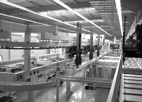
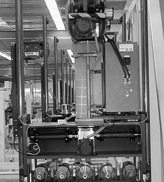
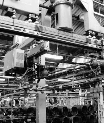
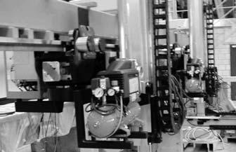
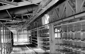
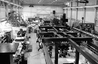
5 Standardschneckengetriebe Réducteur Standard Standard Worm Gear Units Das Programm der Standard Schneckengetriebe umfasst 6 Baugrössen. Jede Baugrösse enthält 8 Übersetzungen. Die Standard- Schneckengetriebe haben ein Flankenspiel zwischen 15 und 18 Winkelminuten und sind nicht nachstellbar. Sie eignen sich für mittelgrosse Leistungsübertragung. Unsere Ingenieure, denen entsprechende Rechnungsprogramme zur Verfügung stehen, helfen Ihnen gerne Ihren Anwendungsfall zu optimieren. Le programme réducteur standard contient 6 taille. Chaque taille est livrable avec 8 rapports différents. Les réducteurs ont un jeu primitif de 15 à 18 minutes est sont pas ajustable. De plus nos ingénieurs, à l aide de programmes de calcule sont à votre disposition afin d optimiser vos applications. Our standard worm gear unit range includes 6 sizes. Each size is available with 8 different ratios.the backlash of the gear is between 15 and 18 arc minutes and are not adjustable. Our engineers which are equipped with calculation programs will be glad to help you to find the right product for your application. Bild 1 Bild 1 Assembly of gear boxes 06.00

6 INHALTSVERZEICHNIS TABLE DES MATIÈRES / CONTENT PRODUKTÜBERSICHT Gamme de produits Product overview BAUKASTEN Le système modulaire The modular system AUSWAHLTABELLE Sélection du Réducteur standard Selection of standard worm gear unit BAUGRÖSSEN 030 Tailles de fabrication 030 Sizes BAUGRÖSSEN: 045 Taille de fabrication: 045 Size: BAUGRÖSSEN: 060 Taille de fabrication: 060 Size: BAUGRÖSSEN: 090 Taille de fabrication: 090 Size: BAUGRÖSSEN: 120 Taille de fabrication: 120 Size: BAUGRÖSSEN: 180 Taille de fabrication: 180 Size: BERECHNUNGSBEISPIEL Exemple de calcul Calculation example WARTUNG Entretien Maintenance EINBAU- UND AUSBAU Montage Assembly MOTOREN APPLIKATIONEN Applications des moteurs Applications of motors


7 PRODUKTÜBERSICHT GAMME DES PRODUITS PRODUCT OVERVIEW Standard-Schneckengetriebe Réducteurs standard Standard worm gear unit


8 An Schneckengetriebe werden höchste Anforderungen gestellt, wie optimale Wärmeabfuhr, Lebensdauerschmierung, universelle Anbaumöglichkeiten, Kupplungsmöglichkeiten, grosse Anzahl möglicher Bauformen. Die Baureihe der Normgetriebe wird diesen Bedürfnissen gerecht. Das Gehäuse besteht aus Aluminiumdruckguss und ist allseitig bearbeitet. Die Schnecken sind aus einem Vergütungsstahl gehärtet und teilweise hartgeschält. Das Schneckenrad besteht aus einer Spezialbronze. Die Paarung erlaubt eine hohe Lebensdauer. On demande de plus grandes performances aux réducteurs à roue et vis sans fin, évacuation optimale des calories, graissage à vie, flexibilité de réalisations et possibilités d accouplements et de montages variés. La génération de réducteurs standards répond à tout ces besoins. Les carlers sont en fonte d Aluminium et usinés sur toutes leurs faces. Les vis sans fin sont en acier de haute résistance, traitées superficellement, et rodées après le traitement, la roue est en bronce moulé par centrifugation. This range of gearboxes have been designed and built with today s market demands in mind. The design gives excellent heat dissipation, universal mounting, different coupling options, and a wide range of versions. All gearboxes are lubricated for long life. The housing is made from die cast aluminium, machined on all faces.the worms are of a special steel, which is hardened and peeled, and the worm gears are made from bronze which has been produced using a centrifugal process. Both guarantee a long working life. Baugrössen Taille Size Übersetzung Ratio 4.63:1 5.57:1 6.83:1 8.6: : :1 23.5:1 47.0:1 Zahnspiel Jeu axial Backlash Arc Min Gewinde Trous de fixation Threads for fixation Durchgangsschrauben Trous de fixation Traversant wholes for fixation Universelle Anbauflansche Flasque universelle Flange for IEC and Servo motors Flansch für IEC-Motoren Bride pour moteur CEI Flange for IEC motors Flansch für Servomotoren Bride pour moteur servo Flange for Servo motors Kombinationsmöglichkeiten Exemple de réalisation Mounting example 06.03
9 WAHL DES STANDARD-SCHNECKENGETRIEBES SÉLECTION DU RÉDUCTEUR STANDARD SELECTION OF STANDARD WORM GEAR UNIT Die Getriebe sind für den Einsatz mit Drehund Gleichstrom-Servomotoren ausgelegt. Die Einheiten werden im Werk mit einem Verzahnspiel von Arc Min eingestellt. Richtlinien für die Getriebewahl Die in der Tabelle aufgeführten Abtriebsmomente T2N (Nm) sind gültig für den Einsatz im stossfreien Betrieb bei 20 C Umgebungstemperatur. Bei höheren Belastungen sind die Tabellenwerte mit den nachstehenden Faktoren zu korrigieren. Zusätzlich zu den erwähnten Betriebsfaktoren ist ein Sicherheitsfaktor einzurechnen, der Ihren Erfahrungen und den anwendungsspezifischen Sicherheitsanforderungen entspricht. Baugrössen 090, 120 und 180: Bei Eintriebs- Drehzahlen über 1500 min -1 und gleichzeitiger Einschaltdauer über 70%, bitten wir Sie mit Güdel Kontakt aufzunehmen. Les réducteurs ont été developpés pour être utilisés avec des moteurs d'asservissement. Sortie d'usine les réducteurs sont réglés avec un jeu de Arc Min. Sélectionner un réducteur Les couples indiquées dans le tableau, T2N (Nm), sont valables pour des applications sans chocs et à 20 C de température ambiante. Pour d'autres conditions les valeurs sont à corriger avec les coefficients selon tableaux. Pour toutes applications paticulières il est nécessaire de mettre un coefficient de sécurité supplémentaire aux coefficients déjà défini dans le tableau, celui-ci correspondant à chacune des applications client.tailles 090, 120 et 180: En cas de vitesse de rotation à l entrée supérieure à 1500 min -1 et un cycle de fonctionnement supérieur à 70% veuillez contacter Güdel s.v.p. These high performance worm gearboxes were especially developed for use in high performance Servo-Driven Systems. The units are set up in the factory with a backlash Arc Min. Selecting a unit The nominal torque T2N (Nm) is valid for applications that run under normal shock free operations and at an ambient temperature of 20 C. Other conditions have to be corrected by factors shown below. For specific applications it may be necessary to consider a safety factor, in addition to the factors alredy mentioned in the catalogue.this factor must be based on the customer s experience and any regulations specific to the application. Sizes 090, 120 and 180: In the case of an input speed higher than 1500 min -1 with a duty cycle higher than 70%, please contact Güdel. T2N Mech. T2 fb fa T2N Mech. T2 ft fed Beide Gleichungen müssen erfüllt sein / both required / les deux équation doit remplir la condition Betriebsfaktor / Coefficient de marche / Service coefficient Antrieb Polynomia Standard Servo / Sinus 2 FU/VFD AC-Motor Exter Output-shock fb Anlauffaktor / Coefficient de démarrage / Starting factor Anlaufhäufigkeit / Fréquence de démarrage / Starting frequency 60/h 360/h 1200/h 3600/h fa Temperaturfaktor / Coefficient de température / Temperature factor Umgebungstemperatur / Température ambiante / Ambient temperature 10 C 20 C 30 C 40 C 50 C ft Einschaltdauerfaktor / Coefficient de service / Duty factor Einschaltdauer / Cycle de service / Duty cycle 25% 40% 60% 70% 100% fed T2 (Nm): Drehmoment der Maschine / Couple de la machine / Required torque for driven machine Zulässige Belastungen auf die Abtriebswelle Treten neben hohen Radialkräften gleichzeitig Axialkräfte auf, erbitten wir um Rückfrage Fig. ➀. Charges admissibles au niveau de l arbre de sortie Si les charges radiales et axiales sont très importantes nous vous prions de nous consulter Fig. ➀. Permissible output shaft loads In case of very high radial and axial loads please contact us Fig. ➀. Typ L1 (mm) F1Max (N) L2 (mm) F2Max (N) Fig. ➀
10 Leistungstabellen Tableau des caractéristiques Efficiency tables n1 (min -1 ) Typ i T2max P1 T2N η P1 T2N η P1 T2N η P1 T2N η P1 T2N η P1 T2N η / / / / / / n1 (min -1 ) : Eintriebsdrehzahl / Vitesse d entrée / input speed T2Max (Nm) : Max. Drehmoment bei Not Aus / Couple max. en cas d arrêt d urgence / Max. torque in case of ergency stop. T2N (Nm) : Nenndrehmoment am Abtrieb / Couple de sortie nominale / Nominal output torque P1 (kw) : Eintriebsleistung / Puissance d entrée / Input power η : Wirkungsgrad / Rendement / Efficiency 06.05
11 BAUGRÖSSE 030 TAILLE 030 SIZE 030 Standard-Schneckengetriebe Réducteur standard Standard worm gear unit a = 30 mm Pos. ➀ NA 030 / R NA 030 / L NH 030 Pos. ➀ Getriebe / Réducteur / Worm gear unit Type Part No. Ratio Inertia i J red (10-7 kg m 2 ) m (kg) NA 030 / R : NA 030 / L :1 30 NA 030 / S :1 25 NA 030 / S :1 21 NA 030 / S :1 18 NH :1 17 NH 030 / S : :
12 Bauart mit Abtriebswelle Exécution à arbre de sortie Execution with output shaft NA030/R NA030/L NA030/S1 NA030/S3 NA030/S4 Bauart mit Abtriebshohlwelle Exécution à arbre creux de sortie Execution with hollow output shaft NH 030 NH030/S3 Bestellbeispiel Exemple de commande Ordering example Pos. ➀ NA 030 / S4: i: 47:1 Berechnungsbeispiel / exemple de calcul / calculation example Page Wartung und Schmierung / entretien et lubrification / maintenance and lubrication Page
13 BAUGRÖSSE 030 TAILLE 030 SIZE 030 Standard-Schneckengetriebe Réducteur standard Standard worm gear unit a = 30 mm 20 < L < 33 L ausgelegt für Flansch mit t 1 = 12mm L sur la base d une épaisseur de flange t 1 = 12mm L based on a flange thickness t 1 = 12mm Pos. ➄ Pos. ➃ Pos. ➀ FA 030 / R DIN Fig. ➁ Fig. ➀ FA 030 / L FH 030 Pos. ➀ Getriebe / Réducteur / Worm gear unit Type Part No. Ratio Inertia L i J red (10-7 kg m 2 ) m (kg) FA 030 / R : FA 030 / L :1 30 FA 030 / S :1 25 FA 030 / R-S :1 21 FA 030 / L-S :1 18 FA 030 / S :1 17 FH : FH 030 / S :

 T1max (Nm) MA (Nm) m (kg) 403 023 ➀ 8 11.5 3.4 M3x16 1.37 0.1 403 022 ➀ 9 11.5 3.8 M3x16 403 025 ➀ 10 11.0 4.0 M3x16 403 021 ➀ 11 11.0 4.7 M3x16 403 020 ➀ 14 11.")


14 Pos. ➃ Flansch / Bride / Flange Pos. ➄ Kupplung / Accouplement / Coupling Fig. ➀ Part No. Fig. S r F t1 t2 D M m (kg) ➀ M ➀ M ➀ M ➀ M ➀ M ➀ M ➀ M ➀ M ➀ M ➁ , ➁ Inertia Part No. Fig. d J (10-6 kg m 2 ) T1max (Nm) MA (Nm) m (kg) ➀ M3x ➀ M3x ➀ M3x ➀ M3x ➀ M3x16 T1max: maximal übertragbares Moment der Kupplung / Couple max. de l accouplement / Maximum torque of coupling MA: Anziehdrehmoment / Couple de serrage / Tightening torque Bauart mit Abtriebswelle Exécution à arbre de sortie Execution with output shaft FA030/R FA030/L FA030/S1 FA 030 / R-S3 FA 030 / L-S3 FA030/S4 Bauart mit Abtriebshohlwelle Exécution à arbre creux de sortie Execution with hollow output shaft FH 030 FH 030 / S3 Bestellbeispiel Exemple de commande Ordering example Pos. ➀ FA 030 / L: i: Pos. ➃ Pos. ➄ :1 Berechnungsbeispiel / exemple de calcul / calculation example Page Wartung und Schmierung / entretien et lubrification / maintenance and lubrication Page Einbau- und Ausbau / montage / fitting Page Angaben für speziellen Flansch und Kupplung Spécification pour la bride de sortie et l accouplement spéciale Specification for special flange and coupling d : [mm] L : [mm] S : [mm] r : [mm] F : [mm] ØM : M : alternativ M t : [mm] [mm] [mm] Motor D : alternativ [mm] 06.09
15 BAUGRÖSSE 045 TAILLE 045 SIZE 045 Standard-Schneckengetriebe Réducteur standard Standard worm gear unit a = 45 mm Pos. ➀ NA 045 / R NA 045 / L NH 045 Pos. ➀ Getriebe / Réducteur / Worm gear unit Type Part No. Ratio Inertia i J red (10-6 kg m 2 ) m (kg) NA 045 / R : NA 045 / L :1 18 NA 045 / S :1 14 NA 045 / S :1 11 NA 045 / S :1 9 NH : NH 045 / S : :
16 Bauart mit Abtriebswelle Exécution à arbre de sortie Execution with output shaft NA045/R NA045/L NA045/S1 NA045/S3 NA045/S4 Bauart mit Abtriebshohlwelle Exécution à arbre creux de sortie Execution with hollow output shaft NH 045 NH045/S3 Bestellbeispiel Exemple de commande Ordering example Pos. ➀ NH 045: i: 8.6:1 Berechnungsbeispiel / exemple de calcul / calculation example Page Wartung und Schmierung / entretien et lubrification / maintenance and lubrication Page
17 BAUGRÖSSE 045 TAILLE 045 SIZE 045 Standard-Schneckengetriebe Réducteur standard Standard worm gear unit a = 45 mm 33 L2 < < L1 < 33 L ausgelegt für Flansch mit t 1 = 14mm L sur la base d une épaisseur de flange t 1 = 14mm L based on a flange thickness t 1 = 14mm Pos. ➄ Pos. ➃ Pos. ➀ FA 045 / R DIN Fig. ➁ Fig. ➀ FA 045 / L FH 045 Pos. ➀ Getriebe / Réducteur / Worm gear unit Type Part No. Ratio Inertia L1 L2 i J red (10-6 kg m 2 ) m (kg) FA 045 / R : FA 045 / L :1 18 FA 045 / S :1 14 FA 045 / R-S :1 11 FA 045 / L-S :1 9 FA 045 / S : FH : FH 045 / S :
18 Pos. ➃ Flansch / Bride / Flange Pos. ➄ Kupplung / Accouplement / Coupling Fig. ➀ Part No. Fig. S r F t1 t2 D M m (kg) ➀ M ➀ M ➀ M ➀ M ➀ M ➀ M ➀ M ➀ M ➀ M ➀ M ➀ M ➁ ø ➁ ø7 Inertia Part No. Fig. d J (10-6 kg m 2 ) T1max (Nm) MA (Nm) m (kg) ➀ M4x ➀ M4x ➀ M4x ➀ M4x ➀ M4x16 T1max: maximal übertragbares Moment der Kupplung / Couple max. de l accouplement / Maximum torque of coupling MA: Anziehdrehmoment / Couple de serrage / Tightening torque FA045/R FA045/L FA045/S1 FA 045 / R-S3 FA 045 / L-S3 FA045/S4 FH 045 FH 045 / S3 Bestellbeispiel Exemple de commande Ordering example Pos. ➀ FA 045 / S1: i: Pos. ➃ Pos. ➄ :1 Berechnungsbeispiel / exemple de calcul / calculation example Page Wartung und Schmierung / entretien et lubrification / maintenance and lubrication Page Einbau- und Ausbau / montage / fitting Page Angaben für speziellen Flansch und Kupplung Spécification pour la bride de sortie et l accouplement spéciale Specification for special flange and coupling d : [mm] L : [mm] S : [mm] r : [mm] F : [mm] ØM : M : alternativ M t : [mm] [mm] [mm] Motor D : alternativ [mm] 06.13
19 BAUGRÖSSE 060 TAILLE 060 SIZE 060 Standard-Schneckengetriebe Réducteur standard Standard worm gear unit a = 60 mm Pos. ➀ NA 060 / R NA 060 / L NH 060 Pos. ➀ Getriebe / Réducteur / Worm gear unit Type Part No. Ratio Inertia i J red (10-6 kg m 2 ) m (kg) NA 060 / R : NA 060 / L :1 75 NA 060 / S :1 58 NA 060 / S :1 46 NA 060 / S :1 37 NH :1 31 NH 060 / S : :
20 Bauart mit Abtriebswelle Exécution à arbre de sortie Execution with output shaft NA060/R NA060/L NA060/S1 NA060/S3 NA060/S4 Bauart mit Abtriebshohlwelle Exécution à arbre creux de sortie Execution with hollow output shaft NH 060 NH060/S3 Bestellbeispiel Exemple de commande Ordering example Pos. ➀ NH 060 / S3: i: 11.25:1 Berechnungsbeispiel / exemple de calcul / calculation example Page Wartung und Schmierung / entretien et lubrification / maintenance and lubrication Page
21 BAUGRÖSSE 060 TAILLE 060 SIZE 060 Standard-Schneckengetriebe Réducteur standard Standard worm gear unit a = 60 mm 50 L3 < L2 < < L1 < 40 L ausgelegt für Flansch mit t 1 = 14mm L sur la base d une épaisseur de flange t 1 = 14mm L based on a flange thickness t 1 = 14mm Pos. ➄ Pos. ➃ Pos. ➀ FA 060 / R DIN Fig. ➁ Fig. ➀ FA 060 / L Pos. ➀ Getriebe / Réducteur / Worm gear unit Type Part No. Ratio Inertia L1 L2 L3 i J red (10-6 kg m 2 ) m (kg) FA 060 / R : FA 060 / L :1 75 FA 060 / S :1 58 FA 060 / R-S :1 46 FA 060 / L-S :1 37 FA 060 / S :1 31 FH :1 27 FH 060 / S :1 25 FH 060 Bestellbeispiel Exemple de commande Ordering example Pos. ➀ FH 060: i: Pos. ➃ Pos. ➄ :1 Berechnungsbeispiel / exemple de calcul / calculation example Page Wartung und Schmierung / entretien et lubrification / maintenance and lubrication Page Einbau- und Ausbau / montage / fitting Page
22 Pos. ➃ Flansch / Bride / Flange Pos. ➄ Kupplung / Accouplement / Coupling Fig. ➀ Fig. ➁ Part No. Fig. S r F t1 t2 D M m (kg) ➀ M ➀ M ➀ M ➀ M ➀ M ➀ M ➀ M ➀ M ➀ M ➀ M ➀ M ➁ ø ➁ M10 Inertia Part No. Fig. d J (10-6 kg m 2 ) T1max (Nm) MA (Nm) m (kg) ➀ M6x ➀ M6x ➀ M6x ➁ M4x ➁ M4x16 T1max: maximal übertragbares Moment der Kupplung / Couple max. de l accouplement / Maximum torque of coupling MA: Anziehdrehmoment / Couple de serrage / Tightening torque Fig. ➁ nur mit L3 einsetzbar / Fig. ➁ impose longueur L3 / Fig. ➁ requires lenght L3. Bauart mit Abtriebswelle Exécution à arbre de sortie Execution with output shaft FA060/R FA060/L FA060/S1 FA 060 / R-S3 FA 060 / L-S3 FA060/S4 Bauart mit Abtriebshohlwelle Exécution à arbre creux de sortie Execution with hollow output shaft FH 060 FH 060 / S3 Angaben für speziellen Flansch und Kupplung Spécification pour la bride de sortie et l accouplement spéciale Specification for special flange and coupling d : [mm] L : [mm] S : [mm] r : [mm] F : [mm] ØM : M : alternativ M t : [mm] [mm] [mm] Motor D : alternativ [mm] 06.17
23 BAUGRÖSSE 090 TAILLE 090 SIZE 090 Standard-Schneckengetriebe Réducteur standard Standard worm gear unit a = 90 mm Pos. ➀ NA 090 / R NA 090 / L NH 090 Pos. ➀ Getriebe / Réducteur / Worm gear unit Type Part No. Ratio Inertia i J red (10-5 kg m 2 ) m (kg) NA 090 / R : NA 090 / L :1 56 NA 090 / S :1 44 NA 090 / S :1 34 NA 090 / S :1 28 NH :1 24 NH 090 / S : :
24 Bauart mit Abtriebswelle Exécution à arbre de sortie Execution with output shaft NA090/R NA090/L NA090/S1 NA090/S3 NA090/S4 Bauart mit Abtriebshohlwelle Exécution à arbre creux de sortie Execution with hollow output shaft NH 090 NH090/S3 Bestellbeispiel Exemple de commande Ordering example Pos. ➀ NA 090 / R: i: 23.5:1 Berechnungsbeispiel / exemple de calcul / calculation example Page Wartung und Schmierung / entretien et lubrification / maintenance and lubrication Page
25 BAUGRÖSSE 090 TAILLE 090 SIZE 090 Standard-Schneckengetriebe Réducteur standard Standard worm gear unit a = 90 mm 62 L2 < < L1 < 62 L ausgelegt für Flansch mit t 1 = 18mm L sur la base d une épaisseur de flange t 1 = 18mm L based on a flange thickness t 1 = 18mm Pos. ➄ Pos. ➃ Pos. ➀ FA 090 / R DIN Fig. ➁ Fig. ➀ FA 090 / L Pos. ➀ Getriebe / Réducteur / Worm gear unit Type Part No. Ratio Inertia L1 L2 i J red (10-5 kg m 2 ) m (kg) FA 090 / R : FA 090 / L :1 56 FA 090 / S :1 44 FA 090 / R-S :1 34 FA 090 / L-S :1 28 FA 090 / S :1 24 FH :1 21 FH 090 / S :1 19 FH 090 Bestellbeispiel Exemple de commande Ordering example Pos. ➀ FA 090 / L: i: Pos. ➃ Pos. ➄ :1 Berechnungsbeispiel / exemple de calcul / calculation example Page Wartung und Schmierung / entretien et lubrification / maintenance and lubrication Page Einbau- und Ausbau / montage / fitting Page
26 Pos. ➃ Flansch / Bride / Flange Pos. ➄ Kupplung / Accouplement / Coupling Fig. ➀ Fig. ➁ Part No. Fig. S r F t1 t2 D M m (kg) ➀ M ➀ M ➀ M ➀ M ➀ M ➀ M ➀ M ➀ M ➀ M ➀ M ➀ M ➀ M ➁ ø ➁ ø ➁ ø14 Inertia Part No. Fig. d J (10-6 kg m 2 ) T1max (Nm) MA (Nm) m (kg) ➀ M8x ➀ M8x ➀ M8x ➀ M8x ➀ M8x ➁ M6x ➁ M6x20 T1max: maximal übertragbares Moment der Kupplung / Couple max. de l accouplement / Maximum torque of coupling MA: Anziehdrehmoment / Couple de serrage / Tightening torque Fig. ➁ nur mit L2 einsetzbar / Fig. ➁ impose longueur L2 / Fig. ➁ requires lenght L2. Bauart mit Abtriebswelle Exécution à arbre de sortie Execution with output shaft FA090/R FA090/L FA090/S1 FA 090 / R-S3 FA 090 / L-S3 FA090/S4 Bauart mit Abtriebshohlwelle Exécution à arbre creux de sortie Execution with hollow output shaft FH 090 FH 090 / S3 Angaben für speziellen Flansch und Kupplung Spécification pour la bride de sortie et l accouplement spéciale Specification for special flange and coupling d : [mm] L : [mm] S : [mm] r : [mm] F : [mm] ØM : M : alternativ M t : [mm] [mm] [mm] Motor D : alternativ [mm] 06.21
27 BAUGRÖSSE 120 TAILLE 120 SIZE 120 Standard-Schneckengetriebe Réducteur standard Standard worm gear unit a = 120 mm Pos. ➀ NA 120 / R NA 120 / L NH 120 Pos. ➀ Getriebe / Réducteur / Worm gear unit Type Part No. Ratio Inertia i J red (10-5 kg m 2 ) m (kg) NA 120 / R : NA 120 / L : NA 120 / S : NA 120 / S : NA 120 / S : NH :1 95 NH 120 / S : :


28 Bauart mit Abtriebswelle Exécution à arbre de sortie Execution with output shaft NA120/R NA120/L NA120/S1 NA120/S3 NA120/S4 Bauart mit Abtriebshohlwelle Exécution à arbre creux de sortie Execution with hollow output shaft NH 120 NH120/S3 Bestellbeispiel Exemple de commande Ordering example Pos. ➀ NA 120 /R: i: 5.57:1 Berechnungsbeispiel / exemple de calcul / calculation example Page Wartung und Schmierung / entretien et lubrification / maintenance and lubrication Page
29 BAUGRÖSSE 120 TAILLE 120 SIZE 120 Standard-Schneckengetriebe Réducteur standard Standard worm gear unit a = 120 mm 79 L3 < L2 < < L1 < 59 L ausgelegt für Flansch mit t 1 = 20mm L sur la base d une épaisseur de flange t 1 = 20mm L based on a flange thickness t 1 = 20mm Pos. ➄ Pos. ➃ Pos. ➀ FA 120 / R DIN Fig. ➁ Fig. ➀ FA 120 / L Pos. ➀ Getriebe / Réducteur / Worm gear unit Type Part No. Ratio Inertia L1 L2 L3 i J red (10-5 kg m 2 ) m (kg) FA 120 / R : FA 120 / L : FA 120 / S : FA 120 / R-S : FA 120 / L-S : FA 120 / S :1 95 FH :1 83 FH 120 / S :1 76 FH 120 Bestellbeispiel Exemple de commande Ordering example Pos. ➀ FA 120 / R: i: Pos. ➃ Pos. ➄ :1 Berechnungsbeispiel / exemple de calcul / calculation example Page Wartung und Schmierung / entretien et lubrification / maintenance and lubrication Page Einbau- und Ausbau / montage / fitting Page
30 Pos. ➃ Flansch / Bride / Flange Part No. Fig. S r F t1 t2 D M m (kg) ➀ M10 1, ➀ MI ➀ MI ➀ M ➀ M ➀ M ➀ M ➀ M ➁ ø ➁ ø ➁ ø18 Pos. ➄ Kupplung / Accouplement / Coupling Fig. ➀ Fig. ➁ Inertia Part No. Fig. d J (10-6 kg m 2 ) T1max (Nm) MA (Nm) m (kg) ➀ M8x ➀ M8x ➀ M8x ➀ M8x ➀ M8x ➁ M6x T1max: maximal übertragbares Moment der Kupplung / Couple max. de l accouplement / Maximum torque of coupling MA: Anziehdrehmoment / Couple de serrage / Tightening torque Fig. ➁ nur mit L2, L3 einsetzbar / Fig. ➁ impose longueur L2, L3 / Fig. ➁ requires length L2, L3. Bauart mit Abtriebswelle Exécution à arbre de sortie Execution with output shaft FA120/R FA120/L FA120/S1 FA 120 / R-S3 FA 120 / L-S3 FA120/S4 Bauart mit Abtriebshohlwelle Exécution à arbre creux de sortie Execution with hollow output shaft FH 120 FH 120 / S3 Angaben für speziellen Flansch und Kupplung Spécification pour la bride de sortie et l accouplement spéciale Specification for special flange and coupling d : [mm] L : [mm] S : [mm] r : [mm] F : [mm] ØM : M : alternativ M t : [mm] [mm] [mm] Motor D : alternativ [mm] 06.25
31 BAUGRÖSSE 180 TAILLE 180 SIZE 180 Standard-Schneckengetriebe Réducteur standard Standard worm gear unit a = 180 mm L ausgelegt für Flansch mit t 1 = 26mm L sur la base d une épaisseur de flange t 1 = 26mm L based on a flange thickness t 1 = 26mm 90 L2 < < L1 < 90 Pos. ➄ Pos. ➃ Pos. ➀ FA 180 / R DIN Fig. ➁ Fig. ➀ FA 180 / L Pos. ➀ Getriebe / Réducteur / Worm gear unit Type Part No. Ratio Inertia L1 L2 i J red (10-5 kg m 2 ) m (kg) FA 180 / R : AE 180 (Seite/Page 07.16) FA 180 / L : FA 180 / S : /2 : : l : l :1 558 i: ab Lager / sur stock / from stock Bestellbeispiel Exemple de commande Ordering example Pos. ➀ FA 180 / R: i: Pos. ➃ Pos. ➄ Einbaulage SU 6:1 Berechnungsbeispiel / exemple de calcul / calculation example Page Wartung und Schmierung / entretien et lubrification / maintenance and lubrication Page Einbau- und Ausbau / montage / fitting Page (Seite/Page 06.29)

 T1max (Nm) MA (Nm) m (kg) 418 020 ➀ 32 4080 240 M10x35 51 3.")


32 Pos. ➃ Flansch / Bride / Flange Part No. Fig. S r F t1 t2 D M m (kg) ➀ M ➀ M ➀ M ➀ M ➀ M ➀ M ➀ M Pos. ➄ Kupplung / Accouplement / Coupling Fig. ➀ Inertia Part No. Fig. d J (10-6 kg m 2 ) T1max (Nm) MA (Nm) m (kg) ➀ M10x ➀ M10x ➀ M10x ➀ M10x ➀ M10x ➀ M10x35 T1max: maximal übertragbares Moment der Kupplung / Couple max. de l accouplement / Maximum torque of coupling / MA: Anziehdrehmoment / Couple de serrage / Tightening torque Bauart mit Abtriebswelle Exécution à arbre de sortie Execution with output shaft FA180/R FA180/L FA180/S1 AE180/R AE180/L (Seite/Page 07.16) Angaben für speziellen Flansch und Kupplung Spécification pour la bride de sortie et l accouplement spéciale Specification for special flange and coupling Motor d : [mm] L : [mm] S : [mm] r : [mm] F : [mm] D : alternativ [mm] ØM : M : alternativ M t : [mm] [mm] [mm] 06.27
33 BERECHNUNGSBEISPIEL EXEMPLE DE CALCUL CALCULATION EXAMPLE 1. Applikation Beschreibung der Anwendung. 2. Anforderungen an Antrieb Kleine Abmasse mit hohen übertragbaren Momenten Positioniergenauigkeit Laufruhe Anzahl Lastwechsel /h 3. Betriebsdaten Dauerbetrieb oder intermettierender Betrieb (Anläufe / h) Einschaltdauer Eintriebsdrehzahl Art der Eintriebsdrehzahl (variabel, kontinuierlich Gewünschte Abtriebsdrehzahl Zu bewegende Masse Gewünschte Geschwindigkeit der bewegten Masse Beschleunigungszeit Art des Einbaus des Zahnstangensystems 4. Umgebung Umgebungstemperatur Feuchtigkeit 5. Konfiguration Zubehör Anbaugeometrie Motor Art des Abtriebs Spezielle Modifikationen, Dimensionen oder Eigenschaften 1. Application Description de l application. 2. Caractéristiques demandés Hautes couples transmissible avec petites dimensions Précision de positionnement Roulement Changement de charge / h 3. Indications Fréquence de démarrage (démarrage / h) Cycle de service Vitesse d'éntrée Caractéristique de la vitesse d'entrée (variable, continuel) Vitesse de sortie exiger Poids à bouger Vitesse exiger du poids Temps d'accélération Position de montage du système d entraînement 4. Environnement Température ambiente Humidité 5. Configuration Accessoires Dimensions pour montage du moteur Modifications spéciales, dimensions ou propriétés 1. Application Description of application. 2. Required features Small sizes with high torques Positioning accuracy Rolling Shock loading 3. Loading Continuous or intermittent (start per hour) Duty cycle Preferred input speed Variable or continuous input speed Desired output speed Moving mass Prefered speed of the moved mass Acceleration time Overhung and thrust loading on shafts Arrangement type of the drive system 4. Environmental Temperature Wet or spray exposure 5. Configuration Accessories Flange mounting provisions for the drive motor Specification of output Special modifications, dimensions or features 1. Gegebene Grössen n 1 = /min n 2 = 250 1/min T 2 = 100 Nm f B = 1.2 p f A = 1.1 p f t = 1.0 p f ed = 1.2 p Données 1. Determine knowns n 1 = l/min n 2 = l/min T 2 = l/min f B = p f A = p f t = p f ed = p Gesucht Dimension von Getriebe. 3. Auslegung des Getriebes 3.1 Übersetzung 2. Demandés Dimension du réducteur. 3. Sélection du réducteur 3.1 Rapport 2. Determine unknowns Dimension of gear box. 3. Selection of gear box 3.1 Ratio n i Getr = = =12 i Getr = 11,25 n2 250 i Getr = 3.2 Erforderliches Drehmoment 3.2 Couple nécessaire T 2erf = T 2 f B f A f 1 f ED = = Nm T 2N aus Tabelle page Bedingung: T 2N T 2erf T 2N du tableau de charge page Condition: T 2N T 2erf 3.2 Required torque T 2erf = Nm T 2N from load table page Condition: T 2N T 2erf Getriebe/réducteur/gear box: FA 090 i = 11,25:1 NA/NH/FA/FH 06.28


34 WARTUNG UND SCHMIERUNG ENTRETIEN ET LUBRIFICATION MAINTENANCE AND LUBRICATION Schmierung Die Getriebe werden im Werk mit einem synthetischen Öl gefüllt. Die Erstfüllung erfolgt mit Glygoyl 460 von Mobil. Jede Nachfüllung muss mit einem ebensolchen synthetischen Öl erfolgen. Bei einschichtigem Betrieb wird nach fünfjähriger Laufzeit ein Ölwechsel empfohlen. Bei dreischichtigem Betrieb empfiehlt sich ein zweijähriger Wechsel. Beim Ölwechsel muss das Getriebe entsprechend durchgespült werden. Getriebekupplung Für die Kupplung ist ein Haftfett zu verwenden. Erstbefettung erfolgt mit Mobilux EP2. Lubrification Les réducteurs sont remplis à l usine avec une huile synthétique. Le plein initial se fait avec de la Glygoyl 460 de Mobil. Chaque plein ultérieur devra également se faire avec une huile synthétique. En cas de travail en une équipe, une vidange d huile devra avoir lieu au bout de cinq ans de marche. En cas de travail en trois équipes, il est recommandé de faire la vidange au bout des deux ans. Lors de vidange d huile, le réducteur devra être rincé de manière appropriée. L accouplement La lubrification initiale de l accouplement se fait avec Mobilux EP2. Lubrication The worm gear unit is filled with a synthetic oil at the factory.the first filling is carried out using Glygoyl 460 from Mobil. Every refill must also be carried out using a synthetic oil of this kind. For single-shift operation, an oil change should take place after five years of operation. For threeshift operation, we recommend an oil change after two years. During the oil change, the gear box must be firstly flushed through. Motor coupling The coupling is initially greased with Mobilux EP2. Schmierstoff Lubrificant Lubricant Texaco Getriebe Réducteur Worm gear unit Mobil Degol BP Energol Pinnacle Tivela Klübersynth Schienen Glygoyl 460 GS 460 SG-XP S 460 GH6-220 Rails Guideways Getriebekupplung L accouplement Coupling Mobilux Aralup BP Energol Multifak Alvania Centoplex Verzahnung EP 2 HLP 2 LS-EP 2 EP 2 EP-2 EP-2 Denture Gear teeth Ölmenge für Getriebe Quantité d huile pour les réducteurs Oil quantity for worm gear units Typ V (cm 3 ) gemäss Typenschild selon plaque according name plate Ölmenge Quantité d huile Oil quantity für Getriebe Typ 180 pour les réducteurs Typ 180 for worm gear units Typ 180 Einbaulange position de montage mounting orientation SS SU SL SL SO 06.29
35 EINBAU UND AUSBAU MONTAGE ASSEMBLY Typ FA / FH / AE Type FA / FH / AE Type FA / FH / AE Montage von Motor und Kupplung ➀ Mode d emploi pour montage du moteur et de l accouplement ➀ Kontrolle des Masses L. Distanz von Flansch auf lnnenring. Procedure for mounting of motor and coupling ➁ Kupplung und Motorwelle fettfrei reinigen. Kupplung auf Motorwelle schieben. Mass L mit der Toleranz /- 0.5 überprüfen und Schrauben leicht anziehen. ➂ Schrauben mit Drehmomentschlüssel gemäss Tabelle anziehen. Typ ➁ DIN M3x16 M4x16 M6x20/M4x16 M8x30/M6x20 M8x30/M6x25 M10x35 MA (Nm) / / / ➃ Motor mit leichter Drehung auf Kupplung schieben. ➄ Fixierung des Motors an das Getriebe. ➂ ➀ Contrôler la côte L, distance entre la bride et la bague intérieure. ➁ Nettoyer l accouplement et l arbre du moteur en éliminant la graisse. Glisser l acccouplement sur l arbre du moteur. Contrôler la cote L avec tolérance / - 0.5, puis serrer modérément les vis. ➂ Serrer les vis conformément au tableau, à l'aide d'une clé dynamométrique. Typ ➃ DIN M3x16 M4x16 M6x20/M4x16 M8x30/M6x20 M8x30/M6x25 M10x35 MA (Nm) / / / ➃ Glisser le moteur sur l'accouplement en exerçant une légère rotation. ➄ Fixer le moteur sur le réducteur. ➀ Check the dimension L, the distance from the flange to the inner bore. ➄ ➁ Clean the coupling and the motor shaft so that it is free of grease. Push the coupling into the motor shaft. Check dimension L with tolerance / - 0.5, and lightly tighten the screws. ➂ Tighten the screws according to the table, using a torque wrench. Typ DIN M3x16 M4x16 M6x20/M4x16 M8x30/M6x20 M8x30/M6x25 M10x35 MA (Nm) / / / ➃ Push the motor into the coupling while rotating slightly. ➄ Secure the motor to the gearbox
36 MOTOREN-APPLIKATION APPLICATION POUR DES MOTEURS MOTOR APPLICATIONS Die Auflistung der Motoren erfolgt gemäss der Anbaubarkeit an die betreffende Getriebegrösse. Für die korrekte Getriebeauslegung sind die Leistungstabellen massgebend. Les moteurs sont classés selon la montabilité avec les tailles de réducteur. Pour la sélection du réducteur le tableau de caractéristiques est déterminant. The motors are listed according to wether the units can be fitted to the gear box size. The correct power ratings have to be determined with the load tables. Baugrösse/Taille/Size Type Part No. Part No FA / FH / AE ABB T4C1 bis C /L T5C2 bis C /L /L T4F1 bis F /L T7F2 bis F /L /L Allen-Bradley 1326AB-B410 /-B420 /-B /L /L AB-B515 / -B520 /-B /L /L AB-B720 / -B730 /-B /L /L F-4030 / F-4050 / F /L F-6100 / F-6200 / F /L /L H /L H-3007 / H /L H /L H-4050 / H-4075 H-6100 / H-6200 / H /L /L H-8350 / H /L AMK DV /L DV /L /L DV /L /L DV /L /L
37 MOTOREN-APPLIKATION APPLICATION POUR DES MOTEURS MOTOR APPLICATIONS Baugrösse/Taille/Size Type Part No. Part No FA / FH / AE Baldor BSM BSM /L BSM /L /L BSM /L /L BSM /L /L Baumüller DS /L DS /L DS /L /L DS /L /L DS /L /L Bosch Rexroth SE-D /L SE-B /L SE-B /L /L SE-LB /L /L SE-B4/-C /L /L SE-B /L /L SR-A SR-A /L SF(R)-A /L SF(R)-A /L /L SF(R)-A /L /L SF(R)-A /L /L Fanuc α β /L α 1/ L ø α 3/ /L /L α 12/22/30/ /L /L β 1/ L L ø β 3/ L L
38 Die Auflistung der Motoren erfolgt gemäss der Anbaubarkeit an die betreffende Getriebegrösse. Für die korrekte Getriebeauslegung sind die Leistungstabellen massgebend. Les moteurs sont classés selon la montabilité avec les tailles de réducteur. Pour la sélection du réducteur le tableau de caractéristiques est déterminant. The motors are listed according to wether the units can be fitted to the gear box size. The correct power ratings have to be determined with the load tables. Baugrösse/Taille/Size Type Part No. Part No FA / FH / AE Georg II Kobold KSY KSY /L KSY /L /L KSY /L /L KSY /L /L Bosch Rexroth MDD / MAC / MKD MDD / MAC / MHD / MKD /L MDD /L /L ø MAC /L /L ø MAC /L ø MDD / MAC / MHD / 060../L MKD /L MDD / MAC / MHD / MKD /L /L MDD / MAC / MKD /L /L MHD /L /L MDD / MAC / MHD / MKD /L /L MDD / MAC / MKD /L /L MHD /L /L
39 MOTOREN-APPLIKATION APPLICATION POUR DES MOTEURS MOTOR APPLICATIONS Baugrösse/Taille/Size Type Part No. Part No FA / FH / AE ISOflux /L / /L / /L /L /L /L /L x.xx /L /L x.xx /L /L x.xx /L x.xx /L x.xx /L x.xx /L x.xx /L , /L , /L x.xx /L , /L x.xx /L x.xx /L /L x.xx /L /L x.xx /L x.xx /L /L x.xx /L /L x.xx /L /L x.xx /L x.xx /L /L x.xx /L /L x.xx /L x.xx /L /L x.xx /L /L x.xx /L /L x.xx /L /L x.xx /L /L x.xx /L , /L , /L
40 Die Auflistung der Motoren erfolgt gemäss der Anbaubarkeit an die betreffende Getriebegrösse. Für die korrekte Getriebeauslegung sind die Leistungstabellen massgebend. Les moteurs sont classés selon la montabilité avec les tailles de réducteur. Pour la sélection du réducteur le tableau de caractéristiques est déterminant. The motors are listed according to wether the units can be fitted to the gear box size. The correct power ratings have to be determined with the load tables. Baugrösse/Taille/Size Type Part No. Part No FA / FH / AE Lenze MDSKS /L MDSKS /L MDSKS /L MDSKS /L MDxKS /L MDxKS /L MDxKS /L MDSKA /L MDxKA /L /L MDxKA /L /L MDxKA /L MDxKA /L MDxKA /L MDxKA /L MDxKA /L Parvex HX / LX /L HX / LX /L /L HX / LX /L /L HS /L /L HD /L /L HS /L /L HD /L /L HS /L /L HD /L /L
41 MOTOREN-APPLIKATION APPLICATION POUR DES MOTEURS MOTOR APPLICATIONS Baugrösse/Taille/Size Type Part No. Part No FA / FH / AE Seidel 6SM SM /L SM /L SM /L SM /L /L SM /L /L SM /L SM /L SM /L /L SM109M 090../L /L Siemens 1 FT5 042/044/ /L FT5 062/064/ /L /L FT5 072/074/ /L /L FT5 102/104*/106*/ /L /L FT5 132*/134*/136*/ /L FT5 070*/071*/073* 060../L FT5 101*/103* 090../L FT6 031/ /L FT6 041*/ /L /L FT6 061/062/ /L /L FT6 081*/082/084/ /L /L /L FT6 102*/105*/108* 090../L /L FT6 132*/134/ /L FK 6 040/ /L /L FK6 060/ /L /L FK6 080/ /L /L /L FK 6 100/101/ /L /L * Kein Siemens Kerntyp 06.36
42 Die Auflistung der Motoren erfolgt gemäss der Anbaubarkeit an die betreffende Getriebegrösse. Für die korrekte Getriebeauslegung sind die Leistungstabellen massgebend. Les moteurs sont classés selon la montabilité avec les tailles de réducteur. Pour la sélection du réducteur le tableau de caractéristiques est déterminant. The motors are listed according to wether the units can be fitted to the gear box size. The correct power ratings have to be determined with the load tables. Baugrösse/Taille/Size Type Part No. Part No FA / FH / AE Yaskawa SGMP-01A3B SGMP-02A3B /L SGMP-04A3B /L SGMP-08A3B /L SGMP-15A3B /L /L SGMG-03A.B -05A.A -06A.B 060../L A.A 090../L SGMG-09A.B 060../L A.A 090../L ø SGMG-12A.B -20A.A 090../L A.B 120../L A.A -30A.B -44A.A SGMG-44A.B -55A.A -60A.B Auf Anfrage -75A.A -1AA.A SGMS-10A.A -15A.A 060../L A.A 090../L SG MS-30A.A -40A.A 060../L A.A 090../L SGMD-22A.AAB 090../L SGMD-32A.AAB 120../L SGMD-40A.AAB 090../L /L


43 Lieferumfang Etendue de la livraison Scope of supply Der vorliegende Katalog umfasst die Komponenten der Linear- und Antriebstechnik. Der Inhalt widerspiegelt die Erfahrung von mehr als 5 Jahrzehnten der Entwicklung und Fertigung von Längsführungen,Verzahnungen und Getriebebau. Das nach ISO 9001: 2000 aufgebaute Qualitätssystem, eine grosse Lagerhaltung und ein weltweites Vertriebsnetz garantieren einen optimalen Kundennutzen. Das umfangreiche Standardprogramm ermöglicht einen schnellen Zugriff auf alle Komponenten. Ein erfahrenes Ingenieurteam hilft Ihnen bei der Auswahl, erarbeitet mit Ihnen Einbauvorschläge und optimiert Ihren Anwendungsfall. Auch Sonderteile nach Ihren Zeichnungen stellen wir gerne für Sie her. Sprechen Sie mit uns! Le catalogue suivant comprend les composants de la technique linéaire et d'entraînement. Le contenu reflète l'expérience de plus de 5 décennies de développement et de fabrication de guides longitudinaux, de dentures et de construction d'engrenages. Le système de qualité élaboré selon ISO 9001: 2000, un stock important et un réseau de distribution mondial garantissent au client un profit optimal. La riche gamme standard permet un accès rapide à tous les composants. Une équipe d'ingénieurs expérimentés vous aidera à choisir, travaillera avec vous des projets de montage et optimisera votre cas d'application. Nous fabriquerons également des pièces spéciales pour vous selon vos dessins. Parlez-nous de vos applications! This catalogue covers all the components of the linear and drive technology. Its content reflects the experience of more than 5 decades in the development and manufacture of linear guides, gears and gearboxes. A quality system based on ISO 9001: 2000, a large inventory and a global distribution network guarantee optimal benefits to the customer. The extensive standard programme makes rapid access to all components possible at all times. An experienced engineering team will help you in your selection, and assist you in drawing up installation proposals and in the optimisation of your application. We will also be pleased to manufacture custom components to your own drawings. Call us!

44 Lieferumfang Etendue de la livraison Scope of supply i

45 Besuchen Sie uns im Internet. Unsere Web-Site wurde völlig neu überarbeitet und bietet Ihne folgende Möglichkeiten. Interessante Neuentwicklungen Produkteübersicht - Komponenten - Module - Robotics - Systems Down-Load Funktionen für Zeichnungsunterlagen Anwendungsbeispiele Messedaten Nous vous invitons à vos connecter sur Internet. à l adresse Notre site a était refait complètement et vous offre les possibilités suivantes: Les nouveautés intéressantes Index des catalogues produits - composants - modules - robotics - systems Chargement des plans de nos produits. Applications Dates de nos participations aux différents Salons d exposition. Visit us on our Homepage Our web-site is completely reworked and offer you following possibilities: Interesting news Overall view of our catalogues - components - modules - robotics - systems Downloads of drawings Applications Dates of our exhibitions i
i +7(495)
") COMPONENTS MODULES ROBOTICS SYSTEMS Linear Technology Linearführungen Racks and pinions Zahnstangen und Ritzel Bevel gears Kegelräder Worm gear units: 06 Standard Worm Gear Units Schneckengetriebe: 06
COMPONENTS MODULES ROBOTICS SYSTEMS Linear Technology Linearführungen Racks and pinions Zahnstangen und Ritzel Bevel gears Kegelräder Worm gear units: 06 Standard Worm Gear Units Schneckengetriebe: 06
Schneckengetriebe 1-stufig
 1-stufig Typ NA, NH, FA, FH Allgemeine Beschreibung Das Norm-Schneckengetriebe gewährleistet dem Konstrukteur eine dauerhafte und elegante Lösung seiner Antriebsprobleme. Die allseitigen Anbaumöglichkeiten
d,f,e/05.08/nr
 COMPONENTS MODULES ROBOTICS SYSTEMS Linear Technology Linearführungen Racks and pinions Zahnstangen und Ritzel Bevel gears Kegelräder Worm gear units: 08 Low Backlash Drive Units Schneckengetriebe: 08
d,f,e/05.08/nr
 COMPONENTS MODULES ROBOTICS SYSTEMS Linear Technology Linearführungen Racks and pinions Zahnstangen und Ritzel Bevel gears Kegelräder Worm gear units: 07 High Performance Servo Worm Gear Units Schneckengetriebe:
Baugrössen Taille 030 045 060 090 120 180 Size Übersetzung Ratio 2:1 3:1 4:1 5:1 6:1 8:1 10:1 13 1 /3:1 16:1 24:1
 BAUKASTEN LE SYSTÈME MODULAIRE THE MODULAR SYSTEM Die AE-Baureihe kompakter Hochleistungs- Servoschneckengetriebe werden in 5 Baugrössen und 10 Untersetzungen hergestellt. Die Baugrösse ist identisch mit
With output shaft, output housing & taper roller bearings. Getriebe mit Abtriebswelle, Kegelrollenlagerung und Gehäuse
 Fine Cyclo - F3C-A With output shaft, output housing & taper roller bearings Getriebe mit Abtriebswelle, Kegelrollenlagerung und Gehäuse Page Seite Type Designation 65 Typenbezeichnung Dimensions 66 Maße
collective trade links pvt. ltd.
 Authorized Distributors collective trade links pvt. ltd. 17, Aryan Corporate Park, Nr. Thaltej Railway Crossing, Thaltej, Ahmedabad-380054. Phone: +91-79-26474700 50 Email: sales@collectivebearings.com
Flanschversion mit output flange & Kegelrollenlagerung bearings
 Fine Cyclo - F2C-A Speed reducer with Flanschversion mit output flange & integrierter integrated taper roller Kegelrollenlagerung bearings Page Seite Type Designation 51 Typenbezeichnung Dimensions 52
SERVO-WORM REDUCER. 800-713-6170 www.andantex.com info@andantex.com
 SERVO-WORM REDUCER 800-713-6170 www.andantex.com info@andantex.com .. GUDEL SERVO-WORM REDUCER INTRODUCTION Andantex, USA has introduced two new products under the brand name and joined forces with world
Edelstahlgetriebe stainless steel gearboxes
 Edelstahlgetriebe stainless steel gearboxes Technische Daten /technical data N e u! N e w! Das besondere Kegelradgetriebe the unique bevel gearbox 1 Spiralkegelgetriebe in Edelstahlausführung VA Spiral
S T I R N R A D G E T R I E B E - M O T O R E N spur geared motors
 S T I R N R A D G E T R I E B E - M O T O R E N spur geared motors P E R F E K T E S Z U S A M M E N S P I E L H O H E F L E X I B I L I T Ä T Per fect interaction great flexibility Durch zahlreiche Anpassungsmöglichkeiten
Units HFUS-2UJ. Technische Daten. Technical Data. Abmessungen. Dimensions
 Units HFUS2UJ Technische Daten Technical Data Die HFUS2UJ Unit zeichnet sich neben dem leistungsfähigen KreuzrollenAbtriebslager insbesondere durch ihre Eingangswelle aus. Die in der Unit gelagerte Eingangswelle
Zubehör Accessories Accessoires
 Seite Page Page 14/2 DA 14/4 Allgemeine Merkmale Drehantrieb General parameters Rotary drive unit Caractéristiques générales Servomoteur rotatif + 16 Zubehör Accessories Accessoires 14/0 Drehantrieb Rotary
Otto Dieterle Spezialwerkzeuge GmbH
 Otto Dieterle Spezialwerkzeuge Gmb Predigerstr. 56, 78628 Rottweil, Germany Fax:+49(0) 741 94205-50 Übersicht System Fix-Profil Overview system Fix-Profil / Aperçu système Fix-Profil Ihr Anspruch - unsere
d,f,e/04.03/nr
 COMPONENTS Linear Technology Linearführungen Racks and pinions Zahnstangen und Ritzel Bevel gears Kegelräder MODULES ROBOTICS Worm gear units: 07 High Performance Servo Worm Gear Units Schneckengetriebe:
PLE - line. technical data
 16 - Serie Serie line Z Lebensdauer lifetime h 30.000 96 1 Wirkungsgrad bei Volllast efficiency with full load % 94 2 90 3 Betriebstemperatur min. min. operating temp. -25 C Betriebstemperatur max. max.
Führungsrolle Galet de guidage Roller for vee bars. Befestigungsflansch Bride de fixation Mounting flange brüniert noirçi black oxide
 BAUGRÖSSE 10 TAILLE 10 SIZE 10 Konstruktionsabmasse Führungsrolle Galet de guidage Roller for vee bars M6x30 9,9 Nm Type Part No. Excenter Ga (µm) Mat. m (kg) FR 10 900 710 1 mm +6/+23 100Cr6 1.3505 0,15
Technische Daten Technical data
 ESP-L Reihe ESP-L Series Technische Daten Technical data Typ [type] Untersetzung [ratio] ESP-L 60 ESP-L 75 ESP-L 100 1-stufig [1-stage] 3/4/5/7/10 Untersetzungen [ratio] 2-stufig [2-stage] 9/12/16/20/25/35/40/49/50/70/100
Gleichstrom-Permanentmagnetmotor DC-Permanent Magnet Motor Type GfmO 5,5 2 Pol Leistung/ power: W
 Gleichstrom-Permanentmagnetmotor DC-Permanent Magnet Motor Type GfmO 5,5 2 Pol Leistung/ power: 10 125 W ESTAN Elektromaschinen und Steuerungsbau GmbH Burgunderstraße 6 D-79418 Schliengen (Germany) 1 Tel:
Hülsenfreilauf / HF One-way Clutch Bearing
 BEARINGS A L L FOR B E YOUR A R IFUTURE N G S Hülsenfreilauf / HF One-way Clutch Bearing Zen Ball Bearings are manufactured to the highest quality for standard and non-standard applications. Our technical
Hypex d.o.o. Alpska cesta 43, 4248 Lesce Slovenija Tel: +386 (0) Fax: +386 (0)
 Fax: +386 (0)") MAINTENANCE INSTRUCTIONS MTJ MRJ SERIES Hypex d.o.o. Alpska cesta, Lesce Slovenija Tel: + (0) 00 Fax: + (0) 0 www.unimotion.eu email: sales@unimotion.eu www.unimotion.eu MTJ MRJ Series OVERVIEW Used symbols
MAINTENANCE INSTRUCTIONS MTJ MRJ SERIES Hypex d.o.o. Alpska cesta, Lesce Slovenija Tel: + (0) 00 Fax: + (0) 0 www.unimotion.eu email: sales@unimotion.eu www.unimotion.eu MTJ MRJ Series OVERVIEW Used symbols
Führungsrolle Galet de guidage Roller for vee bars. Befestigungsflansch Bride de fixation Mounting flange brüniert noirçi black oxide
 BAUGRÖSSE 35 TAILLE 35 SIZE 35 Konstruktionsabmasse Führungsrolle Galet de guidage Roller for vee bars M16x80 200 Nm Type Part No. Excenter Ga (µm) Mat. m (kg) FR 35 900 735 1 mm +11/+33 100Cr6 1.3505
Führungsrolle Galet de guidage Roller for vee bars. Befestigungsflansch Bride de fixation Mounting flange brüniert noirçi black oxide
 BAUGRÖSSE 20 TAILLE 20 SIZE 20 Konstruktionsabmasse Führungsrolle Galet de guidage Roller for vee bars M10x50 48 Nm Type Part No. Excenter Ga (µm) Mat. m (kg) FR 20 900 720 1 mm +6/+23 100Cr6 1.3505 0,50
4. TWINSPIN SELECTION PROCEDURE 4. TWINSPIN AUSWAHLVERFAHREN. 4.1 T, E, H, M series duty cycle. 4.1 Arbeitszyklus T, E, H, M Baureihe
 S E L E C T I O N P R O C E D U R E / A U S W A H L V E R F A H R E N 4. TWINSPIN SELECTION PROCEDURE 4. TWINSPIN AUSWAHLVERFAHREN 4.1 T, E, H, M series duty cycle T 1 T 2 T 3 maximum output torque at
Filter Typ 3~ RFI Filter I0FAExxxF100DxxxxS
 Typennummer I0FAE3xxF100XxxxxS RFI Filter I0FAE4xxF100XxxxxS Filter Typ 3~ RFI Filter I0FAExxxF100DxxxxS Technische Daten Typ E355F E375F E411F 100D... 100D... 100D... Bemessungsstrom [A] 120.0 / 105.0
Motion Control Drives
 Motion Control Drives EPG SERIES Servo Planetengetriebe Servo Planetary Gears 1 Übersicht Ausführungen/Design overview Getriebetyp/Gearbox Einbaulage/Mounting position Vollwelle mit Passfeder/ Solid shaft
Dear Colleague, Please give us a call and let us know how we can assist you. We look forward to talking to you soon. Thank you.
 Dear Colleague, Thank you for visiting our website and downloading a product catalog from the R.M. Hoffman Company. We hope this information will be useful to you in solving the application you are working
Zöllige Radialrillenkugellager - Sondergrössen Inch Series / Commercial Inch Series.
 BEARINGS A L L FOR B E YOUR A R IFUTURE N G S 1 Zöllige Radialrillenkugellager - Sondergrössen Inch Series / Commercial Inch Series Zen Ball Bearings are manufactured to the highest quality for standard
Montageanleitung / Mounting instruction / Manuel de montage. D: Abmessung bis zur Klemme. Mat. Nr Typennummer
 Typennummer RFI Filter I0FAE3xxF100XxxxxS Filter Typ 3~ RFI Filter I0FAE3xxF100XxxxxS Technische Daten Typ E330F E337F E345F 100D 100D 100D Bemessungsstrom [A] 55.00/45.70 69.00/57.00 100.00/86.00 Ableitstrom
Planetengetriebe P planetary gearboxes P
 lanetengetriebe Varianten planetary gearboxes variants lanetengetriebe planetary gearboxes Unsere lanetengetriebe der -Serie bieten Ihnen die bewährte TANDLER-Qualität zum günstigen reis. Das Ziel bei
Dear Colleague, Please give us a call and let us know how we can assist you. We look forward to talking to you soon. Thank you.
 Dear Colleague, Thank you for visiting our website and downloading a product catalog from the R.M. Hoffman Company. We hope this information will be useful to you in solving the application you are working
Kuhnke Technical Data. Contact Details
 Kuhnke Technical Data The following page(s) are extracted from multi-page Kuhnke product catalogues or CDROMs and any page number shown is relevant to the original document. The PDF sheets here may have
d,f,e/04.03/nr 0112129
 COMPONENTS Linear Technology Linearführungen Racks and pinions Zahnstangen und Ritzel Bevel gears Kegelräder MODULES Worm gear units: 06 Standard Worm Gear Units Schneckengetriebe: 06 Standardschneckengetriebe
 Verwenden Sie nur Original-KRONE-Ersatzteile! Das gibt Sicherheit und spart Kosten! Use Original-KRONE parts only This will increase operational reliability and help to save costs! N'utiliser que des piéces
 Verwenden Sie nur Original-KRONE-Ersatzteile! Das gibt Sicherheit und spart Kosten! Use Original-KRONE parts only This will increase operational reliability and help to save costs! N'utiliser que des piéces
 Verwenden Sie nur Original-KRONE-Ersatzteile! Das gibt Sicherheit und spart Kosten! Use Original-KRONE parts only This will increase operational reliability and help to save costs! N'utiliser que des piéces
MINIWIBEX Innengewindewirbelwerkzeuge. MINIWIBEX internal thread whirling tools MINIWBEX fraises a tourbillonner intérieur
 MINIWIBEX Innengewdewirbelwerkzeuge MINIWIBEX ternal thread whirlg tools MINIWBEX fraises a tourbillonner térieur Predigerstr. 56, 78628 Rottweil, Germany Tel.:+49(0) 741 94205-0 Fax:+49(0) 741 94205-50
Gleichstrom-Permanentmagnetmotor DC-Permanent Magnet Motor Type GfmO 14 4 Pol Leistung/power: W
 Gleichstrom-Permanentmagnetmotor C-Permanent Magnet Motor Type GfmO 14 4 Pol Leistung/power: 300 1800 W ESTAN Elektromaschinen und Steuerungsbau GmbH Burgunderstraße 6-79418 Schliengen (Germany) Tel: +49
OPTOELEKTRONIK Vertriebs GmbH
 OPTOELEKTRONIK Vertriebs GmbH Katalog / Catalogue LWL-Weitverkehrsumsetzer / Long distance FO converters Dezember 2003 2003 OPTOELEKTRONIK Vertriebs GmbH. Alle Rechte vorbehalten. Die Vervielfältigung
Diagramm 1 2 A [mm] B [mm] C [mm] D [mm] Abmessungen
![Diagramm 1 2 A [mm] B [mm] C [mm] D [mm] Abmessungen](/thumbs/98/137025716.jpg "Diagramm 1 2 A [mm] B [mm] C [mm] D [mm] Abmessungen") Typennummer RFI Filter I0FAE3xxF100XxxxxS Filter Typ 3~ RFI Filter I0FAE3xxF100XxxxxS Technische Daten Typ E311F E322F E345F 100D... 100S... 100D 100D Bemessungsstrom [A] 29.00 / 22.6 55.00/46.00 100.00/86.00
Typennummer RFI Filter I0FAE3xxF100XxxxxS Filter Typ 3~ RFI Filter I0FAE3xxF100XxxxxS Technische Daten Typ E311F E322F E345F 100D... 100S... 100D 100D Bemessungsstrom [A] 29.00 / 22.6 55.00/46.00 100.00/86.00
Bosch Rexroth - The Drive & Control Company
 Bosch Rexroth - The Drive & Control Company Alle Rechte bei Bosch Rexroth AG, auch für den Fall von Schutzrechtsanmeldungen. Jede Verfügungsbefugnis, wie Kopier- und Weitergaberecht, bei uns. 1 Case study
Montageanleitung / Mounting instruction / Manuel de montage. D: Abmessung bis zur Klemme. Mat. Nr Typennummer
 Typennummer RFI Filter I0FAE3xxF100XxxxXS Filter Typ 3~ RFI Filter I0FAE3xxF100XxxxXS Technische Daten Typ E311F E318F E322F 100D... 100S... 100D... 100D0000S 100D0001S Bemessungsstrom [A] 29.00 / 22.6
SWC SPANNLAGER UND GEHÄUSE SWC RADIAL INSERT BALL BEARINGS AND HOUSING
 SWC SPANNLAGER UND GEHÄUSE SWC RADIAL INSERT BALL BEARINGS AND HOUSING SWC bietet Gehäuseeinheiten bestehend aus einem Spannlager und wahlweise Stehgehäuse (UCP), Zweiloch-Flansch-Gehäuse (UCFL) oder Vierloch-Flansch-Gehäuse
Modularer Klemmrollenfreilauf GL...F2-D2(D3) Modular freewheel, roller type GL...F2-D2(D3)
 Modular freewheel, roller type GL...F2-D2(D3)") Modularer Klemmrollenfreilauf GL...F2-D2(D3) Modular freewheel, roller type GL...F2-D2(D3) Modell GL...F2-D2(D3) Die GL...F2-D2(D3) Serie ist gekennzeichnet durch Passungen zwischen dem Freilauf GL, dem
Modularer Klemmrollenfreilauf GL...F2-D2(D3) Modular freewheel, roller type GL...F2-D2(D3) Modell GL...F2-D2(D3) Die GL...F2-D2(D3) Serie ist gekennzeichnet durch Passungen zwischen dem Freilauf GL, dem
Montageanleitung / Mounting instruction / Manuel de montage. D: Abmessung bis zur Klemme. Mat. Nr Typennummer
 Typennummer RFI Filter I0FAE1xxX100XxxxxS Filter Typ 1~ RFI Filter I0FAE1xxB100XxxxxS 3~ RFI Filter I0FAE1xxF100XxxxxS Technische Daten Typ E137B E175B E175F 100L... 100L... 100S... 100D... 100S... 100D...
Schnellwechselsystem : es ist nicht nötig, den Grundhalter vom Werkzeugträger zu entfernen! Voreinstellung ausserhalb der Maschine ist möglich.
 Modular tool-holders system Modulares Werkzeugssystem Système modulaire de porte-outils Sections Querschnitte Sections 10 x 12 mm 12 x 12 mm 16 x 16 mm Torx 20 5 Nm Quick change, without having to remove
Right of alteration without prior notice reserved
 DC-Getriebemotor P26-M28x10 Planetengetriebe P26 mit M28x10 DC-Gearmotor P26-M28x10 Planetary Gearhead P26 with motor M28x10 Massbild Dimensions Änderungen vorbehalten Right of alteration without prior
1 225 cm IP X4 SLI/FL IP24. Montage-Anleitung Instructions de montage Assembling instructions. 60 cm 0
 Sensor-Schalter aussen unten links und rechts SLI/FL IP Interrupteurs sensitifs en bas à l'extérieur à gauche et à droite Sensor switches outside left and right below Arbeiten an den elektrischen Anlagen
Zahnstangen geschliffen, gerade & schräg Racks Ground, Straight & Helical Seiten pages B 3 - B 6
 Zahnstangen Racks Lagerprogramm Stock Programme Inhalt Content Zahnstangen geschliffen, gerade & schräg, Verzahnungsqualität 5 - NEU Racks Ground, Straight & Helical, Toothing Quality 5 - NEW Seiten pages
Motorenreihe Einphasen Wechselstrom
 Einphasen Wechselstrommotorensingle phase motors enreihe Einphasen Wechselstrom line single-phase Eckdaten Key data n s Gehäusematerial Frame material Number of poles Leistung Output 63 bis 100 63 to 100
-BOO- - F - 24 V DC 100 % ED
 e s Bestellformel 4 -BOO- - F - 24 V DC ED Order specifications Drehmagnet Rotary solenoid Größe (,, 9) Size (,, 9) Drehwinkel 2 4 2 4 Angular travel 2 4 6 9 Ausführung beidseitiges Wellenende Anschlussart
Produktbeschreibung CSD-2A Product Description CSD-2A
 Produktbeschreibung Product Description Einbausätze Baureihe Die Harmonic Drive Einbausätze der Baureihe zeichnen sich durch eine im Vergleich zur HFUC-2A Baureihe um fast 50 % verringerte Baulänge aus.
IDG. Drehzahlsensor / Speed Sensor
 Drehzahlen sicher erfassen, anzeigen und kontrollieren For reliable measurement, control and indication of rotational speeds Analogsignal 1-Kanal 1-channel analog signal IDG Drehzahlsensor / Speed Sensor
UNENDLICHE KOMBI- MÖGLICHKEITEN
 SCHLITTENPROFIL-SYSTEM: ergänzt in idealer Weise den Profilbaukasten von FM SYTEME für Einrichtungen zum verschieben und bewegen verändern und einstellen justieren und positionieren manuel oder angetrieben
Deceleration Technology. Rotary Dampers mit hohem Drehmoment WRD-H 2515 WRD-H 3015 WRD-H 4025 WRD-H
 Rotary Dampers mit hohem Drehmoment WRD-H 2515 WRD-H 3015 WRD-H 4025 WRD-H 6030 Deceleration Technology ONLINE CALCULATION AND 2D / 3D CAD DOWNLOAD M m L F Benefits Material: - Aluminium and steel Applications:
Baureihe Series PKA/PKB
 Spielfreie Metallbalgkupplungen Backlash-free Metal Bellow Couplings Baureihe Series PKA/PKB DE EN 09 2011 Partner for performance www.gerwah.com Spielfreie Metallbalgkupplung Backlash-free Metal Bellow
Schnellwechselsystem : Es ist nicht nötig, den Grundhalter vom Werkzeugträger zu entfernen! Voreinstellung ist ausserhalb der Maschine ist möglich.
 Modular tool-holders system with inner coolant Modulares Werkzeugsystem Système modulaire de porte-outils avec arrosage intérieur Quick change, without having to remove the tool-holder from the gang! Presetting
KRUPP Drehantriebe / rotary drives
 KRUPP Drehantriebe / rotary drives Ein Unternehmen von ThyssenKrupp Services ThyssenKrupp GfT Tiefbautechnik TK Systembeschreibung KRUPP Drehantriebe basieren auf Jahrzehntelanger Erfahrung in der Entwicklung
PE VO LON wheels with plain bearing
 Flanged Grooved Wheels PE VO LON -Räder mit Gleitlager PE VO LON wheels with plain bearing PE VO LON wheels with plain bearing Kunststoff auf Polyamidbasis. Räder in schwerer Ausführung mit wartungsfreiem
Deceleration Technology. Rotary Dampers with high-torque range WRD-H 7550 WRD-H 9565 WRD-H
 Rotary Dampers with high-torque range WRD-H 7550 WRD-H 9565 WRD-H 12070 Deceleration Technology ONLINE CALCULATION AND 2D / 3D CAD DOWNLOAD M m L F Benefits Material: - Aluminium and steel Applications:
Test Report. Test of resitance to inertia effects of Zirkona Backwall. Sled Test (Frontal Impact) 20 g / 30 ms
 20 g / 30 ms") Test Report Test of resitance to inertia effects of Zirkona Backwall Sled Test (Frontal Impact) 20 g / 30 ms This report serves solely as a documentation of test results. 93XS0002-00_TdC.doc Page 1 1.
Test Report Test of resitance to inertia effects of Zirkona Backwall Sled Test (Frontal Impact) 20 g / 30 ms This report serves solely as a documentation of test results. 93XS0002-00_TdC.doc Page 1 1.
catalogo INNESTI MECCANICI
 catalogo INNESTI MECCANICI INNESTI MECCANICI EMBRAYAGES MÉCANIQUES MECHANICAL COUPLINGS MECHANISCHE KUPPLUNGEN INNESTI MECCANICI SERIE 30100-30300 - 30500 Gli innesti meccanici di ns. produzione sono bidirezionali
Veraflex Das Profil-System. Veraflex Le système de profilés
 Veraflex Das Profil-System Veraflex Le système de profilés 11 VERAFLEX-Anwendungen Rettungsfahrzeuge Laden- und Inneneinrichtung Möbel Messestände Lagereinrichtungen Applications de VERAFLEX Véhicules
Power supply Interference suppressed acc. to DIN EN /- 4, EN 55011, EN CI. B, power factor corrected Power factor BöSha LED driver
 Operating Instructions LED Mast Double Luminaire Callisto SC DB, incl. Inclination Adjustment, Single-Chip Technology (Please, read carefully before starting operation) Version: 16.01.2017 Model 369-M
 Verwenden Sie nur Original-KRONE-Ersatzteile! Das gibt Sicherheit und spart Kosten! Use Original-KRONE parts only This will increase operational reliability and help to save costs! N'utiliser que des piéces
 Verwenden Sie nur Original-KRONE-Ersatzteile! Das gibt Sicherheit und spart Kosten! Use Original-KRONE parts only This will increase operational reliability and help to save costs! N'utiliser que des piéces
 Verwenden Sie nur Original-KRONE-Ersatzteile! Das gibt Sicherheit und spart Kosten! Use Original-KRONE parts only This will increase operational reliability and help to save costs! N'utiliser que des piéces
 Verwenden Sie nur Original-KRONE-Ersatzteile! Das gibt Sicherheit und spart Kosten! Use Original-KRONE parts only This will increase operational reliability and help to save costs! N'utiliser que des piéces
Hypex d.o.o. Alpska cesta 43, 4248 Lesce Slovenija Tel: +386 (0) Fax: +386 (0)
 Fax: +386 (0)") MAINTENANCE INSTRUCTIONS CTV SERIES Hypex d.o.o. Alpska cesta, Lesce Slovenija Tel: + (0) 5700 Fax: + (0) 570 www.unimotion.eu email: sales@unimotion.eu www.unimotion.eu OVERVIEW Used symbols Remark, note
MAINTENANCE INSTRUCTIONS CTV SERIES Hypex d.o.o. Alpska cesta, Lesce Slovenija Tel: + (0) 5700 Fax: + (0) 570 www.unimotion.eu email: sales@unimotion.eu www.unimotion.eu OVERVIEW Used symbols Remark, note
Snap-in switch for switches PSE, MSM and MCS 30
 Product manual Snap-in switch for switches PSE, MSM and MCS 30 CONTENTS 1. PRODUCT DESCRIPTION 2. DATA AND DIMENSIONAL DRAWINGS 2.1. Technical Data 2.2. Dimensions of PSE with a Mounting Diameter 19 mm
PLANETENGETRIEBE SPN-ECO (E2)
") www.spn-hopf.de PLANETENGETRIEBE SPN-ECO (E2) Planetary gearboxes SPN ECO (E2) Inhalt Content Planetengetriebe Planetary gearboxes SPN-Getriebe und Ritzel 3 SPN gearboxes and pinions SPN-ECO E2-Serie 4
www.spn-hopf.de PLANETENGETRIEBE SPN-ECO (E2) Planetary gearboxes SPN ECO (E2) Inhalt Content Planetengetriebe Planetary gearboxes SPN-Getriebe und Ritzel 3 SPN gearboxes and pinions SPN-ECO E2-Serie 4
BT 4. Bügelschellen U-bolt clamps Collier arceau
 Bügelschellen U-bolt clamps Collier arceau BT 4 BT 4.1. Rundstahlbügelschellen ähnlich DIN 3570 BT 4.1. U-bolt clamps similar to DIN 3570 BT 4.1. Collier arceau semblable à DIN 3570 BT 4.2. Flachstahlbügelschellen
High Technology for Professionals
 LMKAS 10 10 9.8 6.2 0.2 1.2 3 10 13 623 LMKAS 13 13 12 7.2 0.2 1.4 3 13 20 624 LMKAS 16 16 15.8 10.5 0.3 1.5 3 23 30 LMKAS 16 i 16 15.8 10.5 0.15 1.4 3 3 4.5 625-634 LMKAS 16 a 16 15.8 10.5 0.2 1.35 3
Planetary Screw Assembly
 1 Planetary Screw Assembly (PLSA = Planetary Screw Assembly) Customer Presentation 1 Your Requirements Screw assemblies with high power density offered at market-oriented prices High load capacities, high
Bauform A Bauform B * Bauform A Bauform C. Horizontal Horizontal Vertikal mit Hängefeder Vertikal mit Einlegering
 Beschreibung Schalenkupplungen sind drehstarre Kupplungen und zuverlässige Wellenverbindungen, die Stösse und radiale oder axiale wirkende en ertragen können. Die gekuppelten Wellen müssen genau fluchten.
Worm Gearboxes SG Schneckengetriebe SG
 Worm Gearboxes Schneckengetriebe Worm Gearboxes Schneckengetriebe The gearbox output shaft runs in selflubricating sintered bushes, as standard, there is a single output shaft on the left-hand side. Special
Schwerlast-Linear-Systeme Heavy load-linear-systems Linearachsen Linear axis
 Schwerlast-Linear-Systeme Heavy load-linear-systems Linearachsen Linear axis WINKEL RLE-Roboter-Achsen Stahlprofilbauweise mit Kugelumlaufführungen High Dynamic, High Precision-Ausführung mit Servomotoren
Motorenreihe Einphasen Wechselstrom
 enreihe Einphasen Wechselstrom line single-phase Eckdaten Key data n s Gehäusematerial Frame material Number of poles Leistung Output 63 bis 100 63 to 100 Aluminium Aluminum 2 und 4 2 and 4 0,12 bis 3
FlightSim Commander Database Manager 9.5
 FlightSim Commander Database Manager 9.5 Compatible with Lookheed Martin Prepar3D 1.0, 1.4 and Prepar3D v 2.0 The most recently updated database of the Prepar3D version is at the start of FlightSim Commander
Walter Buchmayr Ges.m.b.H.
 Seite 1/10 Chapter Description Page 1 Advantages 3 2 Performance description 4 3 Settings 5 4 Options 6 5 Technical data 7 6 Pictures 8 http://members.aon.at/buchmayrgmbh e-mail: walter.buchmayr.gmbh@aon.at
Motor code for semihermetic. compressors
 KT-410-4 für halbhermetische Hubkolbenverdichter for semihermetic reciprocating compressors pour compresseurs à pistons hermétiques accessibles Im Hinblick auf die verschiedenen Stromnetze bietet BITZER
Qualität Quality Breite / width 19 mm Breite / width 24 mm Breite / width 20 mm Breite / width 25 mm
 1/2014 Maße / Dimensions in mm ZC 15 Berechnung und Auswahl für Führungs-n-Triebe Modul 2 schräg verzahnt Integrated rack and pinion drive calculation and selection module 2 helical tooth system / Rack
PI 48 d - Produktinformation xxx. Spindelköpfe. Kupplungsprofil DIN 1809
 2004-02-09 PI 48 d - Produktinformation PI 48 e - product information Spindelköpfe Spindle units 0.5.922.xxx sprofil 1809 Coupling profile 1809 09 / 2003 Die in dieser Produktinformation enthaltenen Informationen
Katalog / Catalogue. - Seite / Page 1/9 - Weyhe, Autoline Nr. Bezeichnung / Description. A RS repair kit
 - Seite / Page 1/9 - Die Informationen in diesem Katalog wurden mit großer Sorgfalt zusammengestellt. Wir übernehmen keine Verantwortung für fehlende oder falsche Angaben. Technische Änderungen vorbehalten.
Zahnstangen vergütet, gerade & schräg Racks Quenched and Tempered, Straight & Helical
 Zahnstangen Racks Lagerprogramm Stock Programme Inhalt Content Zahnstangen geschliffen, gerade & schräg, Verzahnungsqualität 5 - NEU Racks Ground, Straight & Helical, Toothing Quality 5 - NEW Seiten pages
Programmieranleitung CADAS 100 LPG 210
 Programmieranleitung CADAS 100 LPG 210 Küvetten-Test LCK 555 Seite 1 BSB 5 BSB [n] Ausgabe 9804 Achtung! Das Ausgabedatum dieser Programmieranleitung muß mit dem Ausgabedatum der Arbeitsvorschrift der
Spare parts Accessories
 Seite Page Page 7/2 HZF 7/4 Allgemeine Merkmale Hydraulikzylinder mit äußerer Führung General parameters Hydraulic cylinder with external guide Caractéristiques générales Vérin hydraulique avec guidage
TECHNISCHE DATEN TECHNICAL DATA
 SPANNBEREICHE CLAMPING RANGES Do not exceed the maximum allowable clamping ranges! **, **, **, 7** Harte, einteilige Backen Harte, geteilte Backen Hard -piece jaws d d d d d d d d d d 80-7 -0 8-7 - -9
SWC PENDELROLLENLAGER SWC SPHERICAL ROLLER BEARINGS
 SWC PENDELROLLENLAGER SWC SPHERICAL ROLLER BEARINGS SWC bietet sowohl offene als auch abgedichtete Pendelrollenlager in verschiedenen Ausführungen an: Offene Ausführungen: o Zylindrische Bohrung mit Radialluft
Specification. DESIGN Swing check valves for return fl ow prevention in piping systems to be mounted directly between fl anges acc. to DIN.
 Technische Daten BAUFORM Rückschlagklappen zur Rückfl ussverhinderung in Rohrleitungssystemen für den Einbau zwischen DIN Flanschen. ANSCHLUß Flansch DN32 DN500 bemessen für Flansch nach PN16 BETRIEBSDRUCK
Anwendungsbereiche Areas of Application
 Kundenorientierte Lösungen Anwendungsbereiche Areas of Application Wir bieten das ideale System Die Kombinationen aus spielarmen Planetengetrieben mit hochgenauen Ritzeln und Zahnstangen sind höchst energieeffizient,
FICHE TECHNIQUE CYLINDRES DE FREIN ET D EMBRAYAGE. TY-FL x D1-inch x D1-mm x L x C1 x C2 x D2 x AT-PR x R-H x TA1 x Pm x Pi
 Groupe 13-01-02-00 Type machine : No. série machine : CODE : FICHE TECHNIQUE CYLINDRES DE FREIN ET D EMBRAYAGE Exemple Données client TY-FL x D1-inch x D1-mm x L x C1 x C2 x D2 x AT-PR x R-H x TA1 x Pm
Deceleration Technology. Rotary Dampers with high-torque range WRD-H 0607 WRD-H 0805 WRD-H 1208 WRD-H 1610 WRD-H
 Rotary Dampers with high-torque range WRD-H 67 WRD-H 85 WRD-H 128 WRD-H 161 WRD-H 21 Deceleration Technology ONLINE CALCULATION AND 2D / 3D CAD DOWNLOAD M m L F Benefits Applications: - Mechanical and