For Smooth Operations. Montageanleitung. Materialdruckregler MDR Material Pressure Regulator MDR _B1
|
|
|
- Berndt Frank
- vor 5 Jahren
- Abrufe
Transkript


1 For Smooth Operations Montageanleitung Materialdruckregler MDR Material Pressure Regulator MDR _B1 DE Original Montageanleitung EN Assembly instructions
2 2


3 B A 9 C D E 3


4 18 17 F G 19 H I J 4
5 Inhaltsverzeichnis Sicherheitshinweise 6 Bestimmungsgemässe Verwendung 6 Pflichten des Betreibers 6 Grundlegende Sicherheitshinweise 6 Sicherheit- und Gefahrensymbole 7 Sicherheitshinweise für die Benutzung des Produkts 7 Besondere Gefahrenarten 8 Wartung, Instandhaltung und Störungsbeseitigung 8 Produktbeschreibung 9 Technische Daten 10 Bezeichnung der abgebildeten Komponenten (A-J) 11 Montage/Einbau 11 Betrieb 12 Verpackung, Transport und Lagerung 12 Transportschäden 12 Lagerung 12 Ausbildung des Personals 13 Wartung 13 Kundendienst / Support 13 Erweiterungsmöglichkeiten (Option) 14 Zeichnungen und Ersatzteile 14 Stilllegung und Entsorgung 14 Urheberrecht des Herausgebers 14 Wiederverkauf 14 5
6 DE Sicherheitshinweise Lesen Sie diese Montageanleitung sorgfältig durch, um sich mit dem sicheren und rationellen Betrieb dieses Produkts vertraut zu machen. Bewahren Sie das vorliegende Handbuch zu Referenzzwecken auf. Diese Montageanleitung enthält wichtige Vorschriften und Hinweise zum sicheren und sachgerechten Betrieb des Produkts. Sie soll auch dem Bedienungs- und Wartungspersonal helfen Gefahren, Reparaturkosten und Ausfallzeiten zu minimieren und die Zuverlässigkeit und Lebensdauer des Produkts zu erhöhen. Daher ist es wichtig, den Zugang zu diesem Dokument jeder Person, die mit der Betreuung des Produkts beauftragt ist, jederzeit zu gewährleisten. Bestimmungsgemässe Verwendung Das Produkt darf nur in den dafür vorgesehenen Betriebsbedingungen eingesetzt werden. Eine andere oder darüber hinausgehende Nutzung gilt als nicht bestimmungsgemäss. Für Schäden aus nicht bestimmungsgemässer Verwendung haftet der Hersteller nicht. Zur bestimmungsgemässen Verwendung gehören auch: Das Beachten und Einhalten aller Hinweise und Warnungen dieser Montageanleitung. Die Einhaltung der Inspektions- und Wartungsarbeiten. Pflichten des Betreibers Durch den Sicherheitsverantwortlichen des Produktes ist sicherzustellen, dass: nur qualifiziertes Personal mit der Arbeit an dem Produkt beauftragt wird, diese Personen die Montageanleitung bei allen Arbeiten stets verfügbar haben und verpflichtet werden, diese konsequent zu beachten, die für den Einsatzort geltenden Regeln und Vorschriften zur Unfallverhütung, sowie die Einhaltung der Instandhaltungs- und Wartungsarbeiten zu beachten sind. Grundlegende Sicherheitshinweise Für den sicherheitsgerechten Umgang und den störungsfreien Betrieb dieses Produkts ist folgendes zu beachten: Das Produkt darf nicht zweckentfremdet werden. An dem Produkt dürfen keine Veränderungen durchgeführt werden. Der sichere Betriebszustand ist jederzeit zu gewährleisten. Auf Wunsch führen wir eine Geräteschulung durch, um Ihr Personal auf den erforderlichen Kenntnisstand zu bringen. Trennen Sie bei allen Wartungsarbeiten das Produkt von jeglicher Energiezufuhr. Alle Leitungen, Schläuche und Verschraubungen regelmässig auf Undichtigkeiten und äusserliche erkennbare Beschädigungen überprüfen. Beschädigungen umgehend vom Fachpersonal beseitigen und allenfalls durch Originalteile ersetzen. 6
7 DE Schutzeinrichtungen dürfen nur nach Stillstand und Absicherung gegen erneutes Starten des Produkts entfernt werden. Vor jeder Inbetriebnahme des Produkts müssen alle Schutzvorrichtungen sachgerecht angebracht und funktionsfähig sein. Die erforderlichen persönlichen Schutzausrüstungen sind vom Betreiber bereitzustellen. Sicherheitseinrichtungen und Schutzausrüstung sind regelmässig zu überprüfen. Sicherheit- und Gefahrensymbole WARNUNG VOR EINER GEFAHRENSTELLE Warnhinweise sind Informationen über Gefahren, die zu Körperverletzung und/oder Sachschäden führen können. HINWEIS Hinweissymbole geben Ihnen wertvolle Informationen und Anwendungstipps. QUETSCHGEFAHR Warnung vor Quetschgefahr UMWELTGEFÄHRDUNG Schutz der Umwelt durch die fachgerechte Entsorgung der verschiedenen Materialien und deren Zuführung zur Entsorgung. Sicherheitshinweise für die Benutzung des Produkts Alle Teile und Baugruppen sind nach den anerkannten sicherheitstechnischen Regeln entwickelt und gebaut. Dennoch können bei unsachgemässer Verwendung oder Handhabung Gefahren für den Benutzer oder Dritte an dem Produkt oder anderen Sachwerten entstehen. Das Produkt ist nur zu benutzen: nach der bestimmungsgemässen Verwendung. in sicherheitstechnisch, einwandfreiem Zustand. 7
8 DE Besondere Gefahrenarten Elektrische Energie ELEKTRISCHE SPANNUNG Warnhinweis auf elektrische Gefahren, die zu Körperverletzung und/ oder Sachschäden führen können. Hydraulische und Pneumatische Energie HYDRAULISCHE UND PNEUMATISCHE SYSTEME Warnhinweis auf hydraulische und pneumatische Gefahren, die zu Körperverletzung und/ oder Sachschäden führen können. Gefahren durch hydraulische und pneumatische Energie Das Produkt arbeitet je nach Ausführung mit einem hohen hydraulischen und einem pneumatischen Druck (siehe technische Angaben). Zu öffnende Systemabschnitte wie Druckleitungen, Ventile oder Verbraucher sind vor Reparaturbeginn drucklos zu machen. Es darf kein Restdruck vorhanden sein. Gefahren durch Schmierstoffe Die Sicherheitsvorschriften des Schmierstoffherstellers sind zu beachten und dessen Anweisungen strikt zu befolgen. Der Hersteller dieses Produkts lehnt jegliche Haftung ab für Zwischenfälle, die durch das Nichtbefolgen der Vorschriften, Anweisungen und Empfehlungen des Schmierstoffherstellers entstehen. Wartung, Instandhaltung und Störungsbeseitigung Vorgeschriebene Einstell- und Wartungsarbeiten gemäss Wartungsplan müssen fristgerecht durchgeführt werden. Bedienpersonal vor Einstell- und Wartungsarbeiten informieren. Der Hauptschalter ist abzuschalten (falls vorhanden). Energiezufuhr vom Netz trennen und gegen unbeabsichtigte Inbetriebnahme sichern. Pneumatische und/ oder hydraulische Systeme müssen drucklos sein. Sämtliche Schraub- und Armaturenverbindungen auf festen Sitz kontrollieren. Nach Abschluss der Arbeiten sind sämtliche Sicherheitseinrichtungen und alle Betriebsfunktionen zu überprüfen VORSICHT Sämtliche Arbeiten an dem Produkt sind grundsätzlich nur im Stillstand durchzuführen. 8
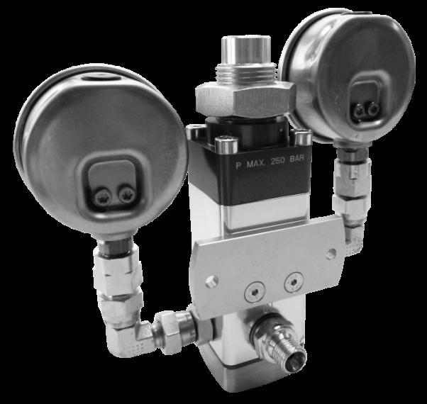
9 DE UMWELTGEFÄHRDUNG Die verschiedenen Materialien/ Flüssigkeiten sind fachgerecht sowie gesondert nach den jeweiligen landesüblichen Vorschriften zu handhaben und entsorgen. Gewährleistung und Haftung Gewährleistungs- und Haftungsansprüche bei Personen- und Sachschäden sind ausgeschlossen, wenn sie auf eine oder mehrere der folgenden Ursachen zurückzuführen sind: Nicht bestimmungsgemässer Verwendung des Produkts. Nicht von qualifizierten Personen durchgeführten Arbeiten. Unsachgemässes Transportieren, Lagern, Montieren, In Betrieb nehmen, Bedienen und Warten des Produkts. Nichtbeachten der Hinweise in der Montageanleitung bezüglich Sicherheit, Transport, Lagerung, Montage, Bedienung, Inbetriebnahme, Wartung und Rüsten des Produkts. Betreiben des Produkts bei defekten Sicherheitseinrichtungen oder nicht ordnungsgemäss angebrachten oder nicht funktionsfähigen Sicherheits- und Schutzvorrichtungen. Konstruktive Veränderungen des Produkts. Verändern der Druckverhältnisse bei der Druckabsicherung und fahren von höheren Drücken als für das Produkt vorgesehen. Mangelhafte Überwachung der Maschinenteile, die einem Verschleiss unterliegen. Unsachgemäss durchgeführte Reparaturen und Benutzung von Fremdteilen. Produktbeschreibung Materialdruck-Reduzierventile reduzieren den Druck des geförderten Materials auf den erforderlichen Arbeitsdruck. Neben der Hauptfunktion der Druckreduzierung, kompensieren diese Ventile auch die bei der Materialförderung durch Kolbenpumpen auftretende Pulsationen, die sich durch die Umschaltpunkte der Pumpe ergeben können. Pulsationen bedeuten hierbei einen kurzzeitigen Druckabfall und führen zu einer geringfügigen Reduktion des Materialflusses. Dies kann z. B. bei Kleinstmengendosierungen zur Verminderung der Produktqualität führen, weil gerade bei solchen Fällen ein absolut gleichmäßiger Materialfluss sichergestellt sein muss. Einsatzbereich (Bild I/J) Materialdruck-Reduzierventile dieser Bauart werden vorzugsweise bei der Verarbeitung von Schmierstoffen eingesetzt. Die Abdichtung des Federraumes erfolgt über eine Gleitringdichtung. Eingesetzt werden diese Ventile für Materialviskositäten von bis mPa s. 9
10 DE HINWEIS In dieser Montageanleitung sind zusätzlich Optionen beschrieben, die möglicherweise nicht in der Ihnen vorliegenden Baugruppe enthalten sind. Diese Montageanleitung umfasst alle möglichen Varianten dieser Baureihe. Technische Daten MDR-LW04 Durchfluss bei mPa s Eingangsdruck Ausgangsdruck Maximaler Druck Mechanische Beständigkeit Chemische Beständigkeit Dichtungsart Ausführung Lufttemperatur (bei Betrieb ohne Material) Relative Luftfeuchtigkeit (bei Betrieb ohne Material) < 0.5l/ min bar 5-50 bar 250 bar keine keine PTFE/FPM mit Kolben/Sitzabdichtung Kugel +5 bis % 10
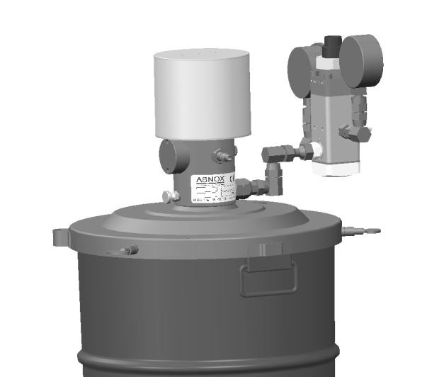
11 DE Bezeichnung der abgebildeten Komponenten (A-J) 1. Einstellschraube 2. Federpaket 3. Kontermutter 4. Kolben 5. Materialausgang/Druckmanometer-Anschluss 6. Ventilsitz 7. Kugel 8. Druckfeder 9. Gewindeplatte 10. Materialeingang/Druckmanometer-Anschluss 11. Befestigungsbohrungen 12. Druckmanometer (Version mit einem Manometer/ Anzeige Ausgangsdruck) 13. Verschlussschraube 14. Druckmanometer (Version mit zwei Manometer/ Anzeige Ein-Ausgangsdruck) 15. Ausgangsdruck senken 16. Ausgangsdruck erhöhen 17. Befestigungsset (Option) 18. Funktionsschema (Anschliessen) 19. Befestigungsset (Option) Montage/Einbau Das Produkt ist am vorhergesehenen Einsatzort unter Berücksichtigung untenstehender Bedingungen aufzustellen oder einzubauen. An Ort und Stelle sind alle gesetzlichen Bestimmungen abzuklären und deren Einhaltung sicherzustellen. Die Boden- und Platzverhältnisse sind vor dem Aufstellen/ Einbau des Produkts abzuklären, um den sicheren Betrieb für Personal und Produkt auf Dauer zu gewährleisten. Das Produkt muss so aufgestellt/ eingebaut werden, dass ein sicherer und dauerhafter Betrieb gewährleistet ist. Das Produkt darf nur von speziell dafür ausgebildeten Fachkräften aufgestellt und in Betrieb genommen werden. Das Produkt ist für Räume gebaut worden, die vor Witterungseinflüssen geschützt sind (Industriestandard). Der Betrieb und die Lagerung in aggressiver, zu feuchter Umgebung oder im Freien können zu Korrosionsschäden führen. 11
12 DE Betrieb Anschliessen Beim Anschliessen sind folgende Punkte zu beachten: Materialeingang/Ausgang beachten (Bild G/Nr.18) Die Einbaulage kann beliebig gewählt werden und hat keinen Einfluss auf die Funktion Materialdruck-Reduzierventil einstellen (Bild I) Das Materialdruck-Reduzierventil reduziert den Eingangsdruck auf einen gewünschten Ausgangsdruck und vermindert Pulsationen (Bild E 15/16). Der Ausgangsdruck wird mit der Einstellschraube (Bild A/Nr.1) eingestellt. Die Einstellung hängt vom Material und deren Viskosität ab. Je nach Arbeitsdruck wird die Einstellschraube mehr oder weniger geöffnet. Dabei soll das Verhältnis zwischen Ein- und Ausgangsdruck nicht grösser als 5:1 sein. Einstellen: 1. Einstellschraube herausdrehen, d.h. Ausgangsdruck auf 0 bar absenken. 2. Betriebsdruck auf mindestens 3 bar einstellen. 3. Anlage starten. 4. Einstellschraube langsam hineindrehen und Ausgangsdruck erhöhen. Verpackung, Transport und Lagerung Das Produkt wird von ABNOX für den Transport zum jeweiligen ersten Bestimmungsort hergerichtet. Die Verpackungseinheit darf keiner Überbelastung ausgesetzt werden. Die Verpackung und deren Inhalt sind vor Feuchtigkeitseinflüssen zu schützen. Die Transporttemperatur zwischen 20 C und + 40 C ist einzuhalten. Transportschäden Werden bei der Eingangskontrolle Transportschäden entdeckt, ist folgende Vorgehensweise zu beachten: Zusteller benachrichtigen (Spediteur etc.) Schadenprotokoll aufnehmen Lieferant informieren Lagerung Die Lagerung und Zwischenlagerung in aggressiver, feuchter Umgebung oder im Freien kann zu Korrosions- und anderen Schäden führen. Die Lagerungstemperatur von 20 C bis +40 C ist einzuhalten. 12
13 DE Ausbildung des Personals Nur geschultes und eingewiesenes Personal, das alle Punkte der Montageanleitung gelesen und verstanden hat, darf an dem Produkt arbeiten. Ebenfalls müssen die einzelnen Betriebszustände beherrscht, sowie die zusammenhängenden Sicherheitsaspekte gekannt und umgesetzt werden können. Anzulernendes Personal darf nur unter Aufsicht von qualifiziertem Personal an dem Produkt arbeiten. Wartung Die angegebenen Wartungsintervalle beziehen sich auf einen Einschichtbetrieb. Je nach Einsatzgebiet, Medium und bei einem Mehrschichtbetrieb muss die Wartung öfters durchgeführt werden. Wann Was Wie Wer Täglich Täglich Sichtkontrolle Reinigung -Schutzeinrichtungen prüfen -Montageanleitung vorhanden? -Sicherheits- Gefahrenhinweise auf Sichtbarkeit prüfen -Dichtheit der Verbindungskupplungen Verschmutzungen durch Material sofort entfernen. Eingetrocknetes Material ist nur sehr schwer zu entfernen. Fachkräfte des Betreibers VORSICHT Sämtliche Arbeiten an dem Produkt sind grundsätzlich nur im Stillstand durchzuführen. Das pneumatische und hydraulische System muss drucklos sein. Die Manometer müssen 0 bar anzeigen. Kundendienst / Support ABNOX AG Langackerstrasse 25 CH-6330 Cham Schweiz GEFAHR Gefahr durch Wartungsarbeiten! Wenn Sie Wartungsarbeiten ohne die notwendige Ausbildung zum Wartungspersonal durchführen, ist die Sicherheit der Baugruppe nicht mehr gewährleistet. Tod oder schwere Körperverletzung können die Folge sein. Beachten Sie alle Sicherheitshinweise und überlassen Sie die Wartung dem ausgebildeten Wartungspersonal. Tel. +41 (0) Fax +41 (0) info@abnox.com Internet 13
14 DE VORSICHT Unfallgefahr und Umweltgefährdung: Fett/Öl auf Böden erhöht die Unfallgefahr. Das Fett/Öl muss fachgerecht, nach landesüblichen Vorschriften, entsorgt werden (Sonderabfall). Erweiterungsmöglichkeiten (Option) Befestigungsset (Bild H/Nr.19): Mit dem Befestigungsset kann bei den Fettversorgungssystemen der ABNOX AG verhindert werden, das der Matetrialdruckregler mit dem Fettversorgungssystem kollidiert. Befestigungsset (Bild F/Nr.17): Mit dem Befestigungsset kann der Materialdruckregler am gewünschten Ort angeschraubt werden. Zeichnungen und Ersatzteile Zubehör, Zeichnungen, Massblätter, Datenblätter und Ersatzteile findet man auf Stilllegung und Entsorgung Bei einer Ausserbetriebnahme /Stilllegung des Produkts sind folgende Punkte zu beachten: Der Hauptschalter ist abzuschalten (falls vorhanden) Der Netzstecker ist vom Netz zu trennen (falls vorhanden) Es darf kein Druck im System vorhanden sein. Das Medium muss entfernt und fachgerecht entsorgt werden. Urheberrecht des Herausgebers Dieses Dokument darf nur mit ausdrücklicher Genehmigung des Herausgebers vervielfältigt, übersetzt oder Dritten zugänglich gemacht werden. Wiederverkauf VORSICHT Die verschiedenen Materialien / Flüssigkeiten sind fachgerecht sowie gesondert nach den jeweiligen landesüblichen Vorschriften zu handhaben und der Entsorgung zu zuführen. Schmierstoffe gelten als Sonderabfall. Diese Montageanleitung ist Bestandteil des Produkts und gehört zum Lieferumfang bei Wiederverkauf. 14
15 DE Contents Safety Warning 17 Proper Use 17 Operator s Obligations 17 Basic Safety Instructions 17 Safety- and Danger Symbols 18 Particular Types of Dangers 18 Safety Instructions for the Use of the Product 18 Maintenance, Service and Troubleshooting 19 Warranty and Liability 20 Product Description 20 Designations of the components shown (Figure A J) 22 Technical Data 21 Assembly/ Installation 22 Operation 23 Packing, Transport and Storage 23 Transport Damages 23 Storage 23 Training of Personnel 24 Maintenance 24 Customer Service/Support 25 Drawings and Replacement Parts 25 Idling and Disposal 25 Publisher s Copyright 25 Re-Sale 25 15
16 EN 16
17 EN Safety Warning Read this Assembly instructions through carefully in order to familiarise yourself with the safe and efficient operation of this product. Keep this handbook for reference purposes. This Assembly instructions contains important instructions and directives for the safe and proper operation of the product. It should also help operating and maintenance personnel to minimise dangers, repair costs and down times and increase the reliability and operational life of the product. For that reason it is important to assure at all times access to this document to everyone who is assigned with the supervision of this product. Proper Use The product may only be used in the operational conditions for which it is designed. Any use that goes beyond this is deemed improper. The manufacturer is not liable for any damages resulting from improper use. Also included in proper use are: Observing and following all instructions and warnings in this Assembly instructions. Completion of inspection and maintenance work as scheduled. Operator s Obligations The party responsible for the safety of the product must make sure that: only qualified personnel are assigned to work with the product, these persons have the Assembly instructions ready to hand during all of their work and are required to follow it consistently, the rules and regulations for the prevention of accidents that apply at the site of use are followed and that the scheduled service and maintenance is completed on time. Basic Safety Instructions For the safe handling and smooth operation of this product, you must heed the following: The product may not be used for purposes for which it was not designed. No modifications may be made to the product. Safe operational condition must be assured at all times. On request, we will hold a training session for the device in order to provide your personnel with the knowledge they need. Disconnect every energy supply when you are performing maintenance on the product. All lines, hoses and screw connections need to be checked for tightness regularly and for externally visible damage. Any damage must be immediately repaired by technicians and if needed replaced with original parts. Safety equipment may only be removed after the product has been completely shut down and secured accident re-start. 17
18 EN Prior to every operational start-up of the product, all safety equipment must be properly replaced and functional. The operator must provide the required personal protective gear. Safety equipment and safety gear must be inspected regularly. Safety- and Danger Symbols WARNING: DANGEROUS LOCATION Warnings are information about dangers that can lead to bodily injuries and/or property damage. INSTRUCTION The instruction symbols give you valuable information and tips on operation. RISK OF CRUSHING Warning against risk of crushing. ENVIRONMENTAL HAZARD Protect the environment by properly disposing of the various materials or assuring they are properly transported to disposal. Safety Instructions for the Use of the Product All parts and assembly groups have been developed and constructed in accord with the recognised rules of safety engineering. However, if it is handled or operated improperly, this can result in dangers to the user or third parties or hazards to the product or to their property. The product must only be used: For its intended purposes. In a proper condition in terms of its safety engineering features. 18
19 EN Particular Types of Dangers Electrical Energy ELECTRICAL VOLTAGE Warning about electrical hazards that can lead to bodily injury and/or property damage. Hydraulic and Pneumatic Energy HYDRAULIC AND PNEUMATIC SYSTEMS Warning about hydraulic and pneumatic hazards that can lead to bodily injury and/or property damage. Hazards from hydraulic and pneumatic energy The product works, depending on configuration, with high hydraulic and pneumatic pressure (see technical information). System sections such as pressure lines, valves or consumers that must be opened must first be depressurised before the start of repairs. There may be no residual pressure. Hazards from lubricants The safety instructions form the lubricant manufacturer must be heeded and its instructions strictly followed. The manufacturer of this product rejects any liability for incidents that result from failure to follow the rules, instructions and recommendations of the lubricant manufacturer. Maintenance, Service and Troubleshooting Prescribed calibration and maintenance work following the maintenance schedule must be completed in a timely fashion. Inform the operating personnel prior to any calibration or maintenance work. Turn off the main switch (if there is one). Disconnect the energy supply from the main network and secure against unintentional reactivation. Pneumatic and/ or hydraulic systems must be de-pressurised. Check all screw connections and armatures for proper fit. Once all work is completed check all safety equipment and operational functions. CAUTION Any and all work on the product may only be carried out when it is idle. 19
20 EN ENVIRONMENTAL HAZARDS The various materials/liquids are to be handled properly and separately disposed of in compliance with the applicable national regulations. Warranty and Liability Warranty and liability claims are excluded in cases of personal injury and property damage if they derive from one or more of the following causes: Improper use of the product. Work completed by unqualified persons. Improper transportation, storage, assembly, operational start-up, operation and maintenance of the product. Failure to heed the instructions in the Assembly instructions regarding safety, transport, storage, assembly, operation, operational start-up, maintenance and equipping the product. Operating the product if safety equipment is defective or not properly installed or if the safety and protective equipment is not functional. Structural modifications to the product. Changing the pressure ratios in the pressure safety and operating at pressures higher than those for which the product is designed. Product Description Material pressure regulators reduce the pressure of the delivered material to the required working pressure. Apart from reducing pressure (main function), these valves compensate for pulsations which occur during material delivery with piston pumps and are due to the changeover position of the pump. Such pulsations would cause a short-time drop of pressure and lead to a slight reduction of the material flow. In case of minimum quantity metering, this might impair product quality as especially for such applications, an absolutely consistent material flow must be ensured. One pressure gauge each for material input and material output pressures can be installed as an option. Field of application (Figure I/J) These types of material pressure reduction valves are primarily used for handling lubricants. The spring chamber is sealed by a slide ring seal. These valves are used for material viscosity values between 5,000 and 500,000 mpa s. Characteristic curve of the material flow rate as a function of viscosity. 20
21 EN NOTE These installation instructions describe additional options which may not be included in the modules you have at hand. These installation instructions cover all available versions of this series. Technical Data MDR-LW04 Flow rate at 50,000mPa s Inlet pressure Outlet pressure Maximum pressure Mechanical resistance Chemical resistance Seal type Design Air temperature (under operation without material) Relative humidity (under operation without material) < 0.5l/min bar 5-50 bar 250 bar none none PTFE/FPM with piston/seated ball seal +5 to % 21
22 EN Designations of the components shown (Figure A J) 1. Adjustment screw 2. Spring set 3. Lock nut 4. Piston 5. Material outlet / pressure gauge port 6. Valve seat 7. Ball 8. Compression spring 9. Threaded plate 10. Material inlet / pressure gauge port 11. Mounting holes 12. Pressure gauge (version with pressure gauge / outlet pressure gauge) 13. Plug screw 14. Pressure gauge (version with two pressure gauges / inlet and outlet pressure gauges) 15. Reduce the outlet pressure 16. Increase the outlet pressure 17. Mounting kit (option) 18. Functional diagram (connecting) 19. Mounting kit (option) Assembly/ Installation The product is to be set up or installed at the intended use site under due consideration of the following conditions: At the location and site all applicable provisions of law must be clarified and compliance with them assured. The ground and space relations are to be clarified prior to set-up/installation of the product in order to assure safe operation for the personnel and the product long-term. The product must be set-up/installed so that safe, permanent operation is assured. The product may only be set up and commissioned by specially trained technicians. The product is constructed for rooms that are protected from the influence of the weather (industry standard). The operation and storage in aggressive or humid environments or outdoors can lead to corrosion damages. 22
23 EN Operation Connecting The following items must be observed when connecting the valve: Observe the material input / output (Figure G/no.18) Any installation position can be used, this has no effect on operation Adjusting the material pressure reduction valve (Figure I) The material pressure reduction valve reduces the inlet pressure to a desired outlet pressure and reduces pulsation (Figure E/no.15/16). The outlet pressure is adjusted with the adjustment screw (Figure A/no.1). The adjustment depends on the material and its viscosity. The adjustment screw is opened to a greater or lesser degree according to the working pressure. The ratio between the inlet and outlet pressure should not exceed 5:1. Adjusting: 1. Turn the adjustment screw out, i.e. adjust the outlet pressure to 0 bar. 2. Set the operating pressure to at least 3 bar. 3. Start the system. 4. Slowly turn the adjustment screw in and increase the outlet pressure. Packing, Transport and Storage The product will be prepared for transport to its first destination by ABNOX. The packing unit may not be subjected to any excess load. The packaging and its content must be protected from moisture. The transport temperature must be kept between 20 C and + 40 C. Transport Damages If transport damages are discovered during the inspection of incoming goods, this procedure must be followed: Inform delivering party (freight carrier, etc.) Make record of damages Inform supplier Storage Storage and temporary storage in aggressive or humid environments or outdoors can lead to corrosion and other damages. The storage temperature must be kept from 20 C to +40 C 23

24 EN Training of Personnel Only trained and instructed personnel who have read and understood all points of the Operating Manual may work on the product. Likewise the individual operating states must be mastered, and the related safe aspects must be known and they must be able to implement them. Personnel undergoing training may only work on the product under the supervision of qualified personnel. Maintenance The indicated maintenance intervals are based on single-shift operation. Depending on the use site, medium and cases of multi-shift operation, maintenance may need to be performed more frequently. When What How Who Daily Daily Visual inspection Cleaning -Test the safety systems -Installation instructions available? -Check the legibility of safety and danger warning signs/labels -Leak tightness of the connection coupling Remove material residue immediately. Dried-on material can only be removed with great difficulty. Operating company technicians DANGER Danger due to maintenance work! The safety of the module is no longer ensured if you perform maintenance tasks without the necessary training as maintenance personnel. Death or severe injury may result. Observe all safety information and leave maintenance up to the trained maintenance personnel. 24
25 EN Expansion options (optional) Mounting kit (Figure H/no.19): Combined with ABNOX AG grease supply systems, the mounting kit can prevent contact between the material pressure regulator and the grease supply system. Mounting kit (Figure F/no.17): With the mounting kit the pressure regulator can be fixed at a suitable place. Customer Service/Support ABNOX AG Langackerstrasse 25 CH-6330 Cham Switzerland Tel. +41 (0) Fax +41 (0) info@abnox.com Internet Drawings and Replacement Parts Accessories, drawings, dimensioning sheets, data sheets and replacement parts can be found at Idling and Disposal When de-commissioning/idling the product, please heed the following points: Switch off the main switch (if any) Unplug the main power plug from the main supply (if any) The system must be depressurised. The medium must be removed and properly disposed of. Publisher s Copyright This document may only be reproduced, translated or made accessible to third parties with the expressed consent of the publisher. Re-Sale ENVIRONMENTAL HAZARD The various materials /liquids must be properly and separately handled and disposed of in compliance with the applicable national ordinances. Lubricants are considered hazardous waste. This Operating Manual is a component of the product and belongs in the scope of delivery in the event of re-sa 25
26 Notes: 26
27 27
28
For Smooth Operations. Montageanleitung. Materialdruckregler MDR-LW _A1
 For Smooth Operations Montageanleitung Materialdruckregler MDR-LW04 0004372_A1 DE Original Montageanleitung EN Assembly instructions 2 1 2 11 3 12 4 B 5 13 6 7 10 8 A 9 C 14 15 16 17 D E 3 19 18/a 7 8
1 Allgemeine Information
 1 Allgemeine Information ACHTUNG! Der Betriebsdruck der Klasse 867 ist 6 bar. Sollte der Druck Ihrer Versorgungsleitung höher als 6 bar sein, muss der Druck an der Versorgungseinheit der Nähmaschine auf
Outdoor-Tasche. Operating Instructions Bedienungsanleitung GB D
 00 181243 Outdoor Case Outdoor-Tasche Splish Splash Operating Instructions Bedienungsanleitung GB D A B C D OPEN G Operating instruction 1. Important Notes Children are not permitted to play with the device.
DE Montageanleitung RG120 Fertigmontage-Set mit Griffeinheit für Absperr-Wasserzähler-Montageblock
 Montageanleitung RG120 Fertigmontage-Set mit Griffeinheit für Absperr-Wasserzähler-Montageblock Installation Manual RG120 External parts with handles for shut-off water meter assembly block Fig. 96 11
DE Gebrauchsanleitung / Montageanleitung 2 EN Instructions for use / assembly instructions 3 E / S / Metris S /
 DE Gebrauchsanleitung / Montageanleitung 2 EN Instructions for use / assembly instructions 3 13423000 / 13424000 31416000 / 31417000 Deutsch Sicherheitshinweise Bei der Montage müssen zur Vermeidung von
Electrical tests on Bosch unit injectors
 Valid for Bosch unit injectors with order numbers 0 414 700 / 0 414 701 / 0 414 702 Parts Kit Magnet*: - F00H.N37.925 - F00H.N37.933 - F00H.N37.934 * For allocation to the 10-place Bosch order number,
Hazards and measures against hazards by implementation of safe pneumatic circuits
 Application of EN ISO 13849-1 in electro-pneumatic control systems Hazards and measures against hazards by implementation of safe pneumatic circuits These examples of switching circuits are offered free
Power Supply ND Series. USER MANUAL BEDIENUNGSANLEITUNG
 Power Supply ND Series USER MANUAL BEDIENUNGSANLEITUNG www.biontechnologies.com USER MANUAL Power Supply ND Series Safety Instructions Devices must be installed by qualified personnel in compliance with
VIDEO CALL CAMERA G-VCAM-01
 VIDEO CALL CAMERA G-VCAM-01 EN AUS GUTEM GRUND ENGLISH 07-10 2 SAFETY AND INFORMATION Safety 7 This camera is designed to transmit video and audio signals. All other uses are expressly prohibited. 7 Protect
WM4L. Höhenverstellbarer Stand. MAX 10kg / (22lbs) jede Ablage MONTAGEANLEITUNG. v.17.11
 jede Ablage MONTAGEANLEITUNG. v.17.11") Höhenverstellbarer Stand MONTAGEANLEITUNG v.17.11 ACHTUNG: NIEMALS DAS MAXIMAL ZULÄSSIGE BELASTUNGSGEWICHT ÜBERSCHREITEN. MISSACHTUNG KANN ZU SACHSCHÄDEN ODER SCHWEREN VERLETZUNGEN FÜHREN! WM4L MAX 10kg
Höhenverstellbarer Stand MONTAGEANLEITUNG v.17.11 ACHTUNG: NIEMALS DAS MAXIMAL ZULÄSSIGE BELASTUNGSGEWICHT ÜBERSCHREITEN. MISSACHTUNG KANN ZU SACHSCHÄDEN ODER SCHWEREN VERLETZUNGEN FÜHREN! WM4L MAX 10kg
Ex-Barriere für Diagnoseeinheit SITRANS DA400 / Ex-barrier for diagnostics unit SITRANS DA400 7MJ2010-1AA 0032
 Ex-Barriere für Diagnoseeinheit SITRANS DA400 / Ex-barrier for diagnostics unit SITRANS DA400 7MJ2010-1AA 0032 Warnung Elektrischer Anschluss in explosionsgefährdeten Bereichen Anschluss und Inbetriebnahme
Service Manual. Powermixer / Mixingdesk PD10.14 / MD circuit diagram. Zeck Audio Service department Turnhallenweg 6 D Waldkirch Germany
 Service Manual circuit diagram Powermixer / Mixingdesk PD10.14 / MD10.14 Zeck Audio Service department Turnhallenweg 6 D-79183 Waldkirch Germany Phone: +49-(0)7681-2004-18 Fax: +49-(0)7681-2004-972 email:
Instructions de montage. Spiegel / Leuchten / SP.1 SP.2 LE.2 LE.3 LE.1 LE.7 LE.4 LE /
 Montageanleitung Montageaanwijzing Monteringsanvisining Instrucciones de montaje Assembly Instruction Instructions de montage Instruzioni di montaggio Spiegel / Leuchten / Mirror Lamps SP.1 SP.2 A LE.1
linea m mounting SET USER MANUAL BEDIENUNGSANLEITUNG
 linea m mounting 90-228 SET plate USER MANUAL BEDIENUNGSANLEITUNG www.biontechnologies.com USER MANUAL linea m mounting 90-228 SET plate Safety Instructions Devices must be installed by qualified personnel
Power supply Interference suppressed acc. to DIN EN /- 4, EN 55011, EN CI. B, power factor corrected Power factor BöSha LED driver
 Operating Instructions LED Mast Double Luminaire Callisto SC DB, incl. Inclination Adjustment, Single-Chip Technology (Please, read carefully before starting operation) Version: 16.01.2017 Model 369-M
ATEX-Check list. Compiled by: Date: Signature: Acceptable practice at the determination of flash point: Closed cup according to ISO 2719
 Fire and explosion hazard ATEX 137 1999/92/EG und ATEX 95 2014/34/EU Danger assessment and determination of explosion protection zone for the test space as well as the installation site ATEX-Check list
Aufbaudose mit Schalter Spacing box with switch. Montageanleitung mounting instructions
 Aufbaudose mit Schalter Spacing box with switch Montageanleitung mounting instructions body head Aufbaudose mit Schalter Montageanleitung S. 2 mounting instructions p. 9 $ 0.2m Sicherheitshinweise Die
Original Betriebsanleitung Entsprechend Maschinenrichtlinie 2006/42/EG
 Lubricating Equipment Metering Technology for Grease and Oil High Pressure Hydraulic Customised Developments Original Betriebsanleitung Entsprechend Maschinenrichtlinie 2006/42/EG Druckluftabfüllgeräte
Release Notes BRICKware 7.5.4. Copyright 23. March 2010 Funkwerk Enterprise Communications GmbH Version 1.0
 Release Notes BRICKware 7.5.4 Copyright 23. March 2010 Funkwerk Enterprise Communications GmbH Version 1.0 Purpose This document describes new features, changes, and solved problems of BRICKware 7.5.4.
Electrical testing of Bosch common rail piezo injectors
 Applies to generation CRI 3: Bosch 10-position order number 0 445 115 = CRI 3-16 (CRI 3.0) 1600 bar 0 445 116 = CRI 3-18 (CRI 3.2) 1800 bar 0 445 117 = CRI 3-20 (CRI 3.3) 2000 bar Tools required: Hybrid
Montageanleitung Installation Manual
 Montageanleitung Installation Manual Inventux X-Series Flachdach Flat Roof 2 Oelschläger Metalltechnik GmbH Hertzstr. 1-3 D-27318 Hoya Telefon: +49 (0) 4251 816 0 Telefax: +49 (0) 4251 816 81 Email: solar@oelschlaeger.de
Electrical testing of Bosch common rail solenoid valve (MV) injectors
 injectors") Applies to MV injector, generation: -CRI 1.0 / 2.0 / 2.1 / 2.2 -CRIN 1 / 2 / 3, with K oder AK plug Bosch 10-position order number Bosch-Bestellnummer CRI: 0 445 110 xxx Bosch-Bestellnummer CRIN: 0 445
Applies to MV injector, generation: -CRI 1.0 / 2.0 / 2.1 / 2.2 -CRIN 1 / 2 / 3, with K oder AK plug Bosch 10-position order number Bosch-Bestellnummer CRI: 0 445 110 xxx Bosch-Bestellnummer CRIN: 0 445
BRUUDT Kennzeichenhalter für die Honda NC750X ab 2016 BRUUDT Tail Tidy for the Honda NC750X 2016 and onwards.
 Montageanleitung Mounting instructions BRUUDT Kennzeichenhalter für die Honda NC750X ab 2016 BRUUDT Tail Tidy for the Honda NC750X 2016 and onwards. Noch einmal vielen Dank, dass Sie sich für unsere Produkte
TV STÄNDER. Bitte überprüfen Sie VOR der Montage den Lochabstand zwischen den VESA Befestigungslöchern an Ihrem Bildschirm! VESA-Befestigungslöcher
 STÄNDER MONTAGEANLEITUNG v.17.01 ACHTUNG: NIEMALS DAS MAXIMAL ZULÄSSIGE BELASTUNGSGEWICHT ÜBERSCHREITEN. MISSACHTUNG KANN ZU SACHSCHÄDEN ODER SCHWEREN VERLETZUNGEN FÜHREN!! Bitte überprüfen Sie VOR der
Snap-in switch for switches PSE, MSM and MCS 30
 Product manual Snap-in switch for switches PSE, MSM and MCS 30 CONTENTS 1. PRODUCT DESCRIPTION 2. DATA AND DIMENSIONAL DRAWINGS 2.1. Technical Data 2.2. Dimensions of PSE with a Mounting Diameter 19 mm
Electrical testing of Bosch common rail Injectors
 Electrical testing of Bosch common rail Injectors Contents: 1. Adapter cable for Hybridtester FSA 050 (article number 0 684 010 050 / 1 687 023 571) 2. Electrical testing of Bosch common rail solenoid
Qube Ofenreling HALTERUNGSSET QUBE-HSR1 / QUBE-HSR2. MONTAGEANWEISUNG Deutsch. Passend für folgende Modelle: QUBE-090 QUBE-105 QUBE-120 QUBE-150
 Qube Ofenreling HALTERUNGSSET QUBE-HSR1 / QUBE-HSR2 MONTAGEANWEISUNG Deutsch DE EN Passend für folgende Modelle: QUBE-090 QUBE-105 QUBE-120 QUBE-150 Version 06/15 Ident-Nr. M100-000-390 Inhaltsverzeichnis
TRH-05. PC-Rechner Halterung. 10kg (22lbs) MAX. MONTAGEANLEITUNG v Deutsch. English
 MAX. MONTAGEANLEITUNG v Deutsch. English") PC-Rechner Halterung MONTAGEANLEITUNG v.18.02 ACHTUNG: NIEMALS DAS MAXIMAL ZULÄSSIGE BELASTUNGSGEWICHT ÜBERSCHREITEN. MISSACHTUNG KANN ZU SACHSCHÄDEN ODER SCHWEREN VERLETZUNGEN FÜHREN! TRH-05 10kg (22lbs)
PC-Rechner Halterung MONTAGEANLEITUNG v.18.02 ACHTUNG: NIEMALS DAS MAXIMAL ZULÄSSIGE BELASTUNGSGEWICHT ÜBERSCHREITEN. MISSACHTUNG KANN ZU SACHSCHÄDEN ODER SCHWEREN VERLETZUNGEN FÜHREN! TRH-05 10kg (22lbs)
EN Instructions for use / assembly instructions 2 DE Gebrauchsanleitung / Montageanleitung 3
 EN Instructions for use / assembly instructions 2 DE Gebrauchsanleitung / Montageanleitung 3 Ecos 14080019 / 14080029 Ecos L 14081019 / 14081029 Novus 70 71020019 / 71020029 Novus 100 71030019 / 71030029
Bosch Rexroth - The Drive & Control Company
 Bosch Rexroth - The Drive & Control Company Alle Rechte bei Bosch Rexroth AG, auch für den Fall von Schutzrechtsanmeldungen. Jede Verfügungsbefugnis, wie Kopier- und Weitergaberecht, bei uns. 1 Case study
Bedienungsanleitung Manual
 NK ZSU 2 ZEITSCHALTUHR DIGITAL 51277 NK ZSU 3 ZEITSCHALTUHR DIGITAL IP44 51301 NK ZSU 4 ZEITSCHALTUHR DIGITAL 93256 NK ZSU 2 TIME SWITCH DIGITAL 51277 NK ZSU 3 TIME SWITCH DIGITAL IP44 51301 NK ZSU 4 TIME
For Smooth Operations. Gebrauchsanweisung. Hochdruck Einhandpresse mit Kettenzylinder High Pressure One-hand Pump Chain Style _A1
 Gebrauchsanweisung Hochdruck Einhandpresse mit Kettenzylinder High Pressure One-hand Pump Chain Style For Smooth Operations 0007111_A1 DE Original Gebrauchsanweisung EN Instruction manual 2 E 1 2 4 6 7
Schaltfunktion function. piping. Technische Änderungen vorbehalten / modifications reserved Stand / stand: 07/2012
 fremdgesteuert externally controlled Schaltfunktion function Elektrischer Anschluss M12x1 electrical connector M12x1 Die Ventile arbeiten als Druckwaage und werden im Bypass eingesetzt. Der Mediumsdruck
OPERATING INSTRUCTIONS
 OPERATING INSTRUCTIONS for Gas Cartridge Adapter CP250 Part no. 144051 and Gas Cartridge Adapter CV300/470 Part no. 144052 CP 250 CV 300/470 144959_V04 Safety Precautions Possible dangers if the safety
i500 Sicherheitsmodul I5MASA000 I5MASA000 safety module Montageanleitung Mounting Instructions
 i500 Sicherheitsmodul I5MASA000 Montageanleitung I5MASA000 safety module Mounting Instructions Allgemeines Erst lesen, dann beginnen 1 1 Allgemeines 1.1 Erst lesen, dann beginnen Lesen Sie vor der Installation
YOYO. Betriebsanleitung. operating instructions
 YOYO Betriebsanleitung operating instructions SICHERHEITS UND GEFAHRENHINWEISE: Der Aufbau dieser Leuchte entspricht der Schutzklasse I. Um diesen Zustand zu erhalten und einen gefahrlosen Betrieb sicherzustellen,
SW-MOTECH GmbH & Co. KG Ernteweg 8/ Rauschenberg Germany. Tel. +49 (0) 64 25/ Fax +49 (0) 64 25/
 64 25/ Fax +49 (0) 64 25/") ATTENTION: The assembly of this product can be complicated and requires a good technical understanding. If you are not sure of how to do this, have a s pecialty garage perform the mounting and service.
ATTENTION: The assembly of this product can be complicated and requires a good technical understanding. If you are not sure of how to do this, have a s pecialty garage perform the mounting and service.
EN Instructions for use / assembly instructions 2 DE Gebrauchsanleitung / Montageanleitung 4. Exafill
 EN Instructions for use / assembly instructions 2 DE Gebrauchsanleitung / Montageanleitung 4 Exafill 58129003 English Safety Notes Gloves should be worn during installation to prevent crushing and cutting
HPS /B Revision: 01
 Hauptständer KTM 0 SM '08 / 0 SM '0 '07 / 0 SM-R '07 '08 Center Stand KTM 0 SM '08 / 0 SM '0 '07 / 0 SM-R '07 '08 Montagehinweise Revision: 0 Mounting Instruction Achtung: Die Kurven- und Bodenfreiheit
OPERATING INSTRUCTIONS Test pump ZG 5.1. and ZG 5.2.
 Elektromotoren und Gerätebau Barleben GmbH OPERATING INSTRUCTIONS Test pump ZG 5.1. and ZG 5.2. Elektromotoren und Gerätebau Barleben GmbH 2 Inhaltsverzeichnis Page 1 Use 4 2 Design features 4 2.1 Test
Materialdruckregler Material pressure regulator
 Rev. 3.11 Zubehör / Accessories Seite / page 29 97974x / 97956x / 97958x Der Materialdruckminderer dient zum Herabsetzen und Ausgleichen von Materialdrücken. Er dämpft Druckschwankungen bei Förderpumpen
Evidence of Performance
 Air permeability, Watertightness, Resistance to wind load, Operating forces, Mechanical properties, Mechanical durability, Impact resistance Expert Statement No. 15-002226-PR01 (02) Product Designation
DE Gebrauchsanleitung / Montageanleitung 2 EN Instructions for use / assembly instructions 3. Talis E²
 DE Gebrauchsanleitung / Montageanleitung 2 EN Instructions for use / assembly instructions 3 Talis E² 31612009 31612019 31612029 Deutsch Sicherheitshinweise Bei der Montage müssen zur Vermeidung von Quetsch-
Partyzelt
 10029443 10029444 Partyzelt Sehr geehrter Kunde, wir gratulieren Ihnen zum Erwerb Ihres Gerätes. Lesen Sie die folgenden Hinweise sorgfältig durch und befolgen Sie diese, um möglichen Schäden vorzubeugen.
DENTAL IMPLANTS BY CAMLOG medical
 IMPLANT PASS DENTAL IMPLANTS BY CAMLOG medical devices made in germany for your well-being and a natural appearance. Personal data Surname First name Address ZIP code City Date of birth Health insurance
SIMATIC ET 200SP Produktinformation für Makros für 2-fach BaseUnit Produktinformation
 SIMATIC ET 200SP Produktinformation Security-Hinweise Siemens bietet Produkte und Lösungen mit Industrial Security-Funktionen an, die den sicheren Betrieb von Anlagen, Systemen, Maschinen und Netzwerken
Einbau- und Montageanleitung Tankabdeckung TopCover Seite 2-4 Assembly and installation instructions Tank Cover - TopCover Page 5-7
 Einbau- und Montageanleitung Tankabdeckung TopCover Seite 2-4 Assembly and installation instructions Tank Cover - TopCover Page 5-7 TopCover DORW3115 17.04.2009 1 / 8 1. Allgemeines 1.1 Verkehrslasten
The luminaire must be installed and main - tained by a suitably qualified person in compliance with latest installation and safety regulations.
 60 640 98 840 640 Deutsch English 27 Ø42/60 SX 967 /76 SX 966 7 /76 SX 966 Ø42/60 SX 967 7 98 Gewicht / Weight : Kg Max. LPH. : 8000mm Aw. : 0,061m² 0 IP66 WEEE-REG.-NR. DE 2402 Montage und Wartung darf
p^db=`oj===pìééçêíáåñçêã~íáçå=
 p^db=`oj===pìééçêíáåñçêã~íáçå= Error: "Could not connect to the SQL Server Instance" or "Failed to open a connection to the database." When you attempt to launch ACT! by Sage or ACT by Sage Premium for
Datenblatt Data sheet
 Wörner GmbH Automatisierungstechnik Rechbergstr. 50 D-73770 Denkendorf T.: +49 (0)711-601 609-0 F.: +49 (0)711-601 609-10 sales@woerner-gmbh.com www.woerner-gmbh.com Datenblatt Data sheet Rücklaufsperre
Kit CSF48. Einbauanleitung / Installation Instructions. Bestell-Nr.: , Gerätesockel ä 2 (V2A; V4A) Stand ä 7 (V2A; V4A)
 Stand ä 7 (V2A; V4A)") Einbauanleitung / Installation Instructions Kit CSF48 Bestell-Nr.: 71111197, 71111198 Gerätesockel ä 2 (V2A; V4A) Stand ä 7 (V2A; V4A) EA005C/07/A2/01.11 71145478 Identifizierung Kit CSF48 1 Identifizierung
Einbauanleitung / Installation Instructions Kit CSF48 Bestell-Nr.: 71111197, 71111198 Gerätesockel ä 2 (V2A; V4A) Stand ä 7 (V2A; V4A) EA005C/07/A2/01.11 71145478 Identifizierung Kit CSF48 1 Identifizierung
HPS.04.696.10000/B Revision: 01. Hauptständer KTM 990 SM-T / SM-R '09 Center Stand KTM 990 SM-T / SM-R '09
 Hauptständer KTM 0 SM-T / SM-R '0 Center Stand KTM 0 SM-T / SM-R '0 Montagehinweise Revision: 01 Mounting Instruction Achtung: Die Kurven- und Bodenfreiheit kann durch einen Hauptständer eingeschränkt
Gartenbrunnen
 Gartenbrunnen 10029934 10029935 10029932 10030994 10029932 10029934 10029935 Sehr geehrter Kunde, wir gratulieren Ihnen zum Erwerb Ihres Gerätes. Lesen Sie die folgenden Hinweise sorgfältig durch und befolgen
Ladeluftkühler / Intercooler Honda Civic Type R Kit-Nr.:
 190001056 - Einbauanleitung / Installation Instruction - Ladeluftkühler / Intercooler Honda Civic Type R Kit-Nr.: 200001086 Wichtige Hinweise! Diese Montageanleitung ist unbedingt vor Beginn der Einbauarbeiten
Deutsch. English. Eine sichere Gerätefunktion ist nur mit zertifizierten Komponenten gewährleistet!
 SIVACON Bauartgeprüfte Niederspannungsschaltanlage S8 OFFW, Form Typ 7, N-Link Design-verified Low Voltage Switchboard S8 OFFW, Form Type 7, N-Link Betriebsanleitung / Operating Instructions S8 Bestell-Nr.
Steuerung von Rolläden / Controlling Roll-down Shutters
 B004 No 1 + No 2 No 3 B014 No 1 + No 2 No 3 6 1 2 3 Automatik Automatic Manuell AUF Manual UP Dämmerungsschalter Photo sensitive switch Manuell ZU Manual DOWN SEMENS AG- Beispielprogramm / Controlling
Mock Exam Behavioral Finance
 Mock Exam Behavioral Finance For the following 4 questions you have 60 minutes. You may receive up to 60 points, i.e. on average you should spend about 1 minute per point. Please note: You may use a pocket
BRUUDT Kennzeichenhalter für die Kawasaki Z800 BRUUDT Tail Tidy fort the Kawasaki Z800
 Montageanleitung Mounting instructions BRUUDT Kennzeichenhalter für die Kawasaki Z800 BRUUDT Tail Tidy fort the Kawasaki Z800 Noch einmal vielen Dank, dass Sie sich für unsere Produkte entschieden haben!
Operating instructions Pneumatic preselect counter Method of counting - adding, with stationary preset number for Panel mounting Type PZV-S-E
 223 025 Operating instructions Pneumatic preselect counter Method of counting - adding, with stationary preset number for Panel mounting Type PZV-S-E for mounting on G or H rail Type PZV-S-E-SGH with automatic
Tube Analyzer LogViewer 2.3
 Tube Analyzer LogViewer 2.3 User Manual Stand: 25.9.2015 Seite 1 von 11 Name Company Date Designed by WKS 28.02.2013 1 st Checker 2 nd Checker Version history Version Author Changes Date 1.0 Created 19.06.2015
Umschaltadapter/ Changeover / Trennadapter Disconnection Adapter für LSA-PLUS NT for LSA-PLUS NT. Montageanweisung Mounting Instructions
 Umschaltadapter/ Changeover / Trennadapter Disconnection Adapter für LSA-PLUS NT for LSA-PLUS NT Montageanweisung Mounting Instructions Der Umschalter dient zum unterbrechungsfreien Umschalten von Installations-drähten
(825M) 2-Draht-Sender
 2-Draht-Sender") Kamera SKS Bussystem 300004 (825M) 2-Draht-Sender 1. Installation Gefahr für Personen durch einen elektrischen Schlag. Verbrennungsgefahr, Geräteschäden und Fehlfunktionen. Bei der Installation sind die
Kamera SKS Bussystem 300004 (825M) 2-Draht-Sender 1. Installation Gefahr für Personen durch einen elektrischen Schlag. Verbrennungsgefahr, Geräteschäden und Fehlfunktionen. Bei der Installation sind die
Downpipe Ford Focus ST MK3 Kit-Nr.:
 190001081 - Einbauanleitung / Installation Instruction - Downpipe Ford Focus ST MK3 Kit-Nr.: 500001025 Wichtige Hinweise! Diese Montageanleitung ist unbedingt vor Beginn der Einbauarbeiten zu lesen. Die
Exercise (Part XI) Anastasia Mochalova, Lehrstuhl für ABWL und Wirtschaftsinformatik, Kath. Universität Eichstätt-Ingolstadt 1
 Anastasia Mochalova, Lehrstuhl für ABWL und Wirtschaftsinformatik, Kath. Universität Eichstätt-Ingolstadt 1") Exercise (Part XI) Notes: The exercise is based on Microsoft Dynamics CRM Online. For all screenshots: Copyright Microsoft Corporation. The sign ## is you personal number to be used in all exercises. All
Exercise (Part XI) Notes: The exercise is based on Microsoft Dynamics CRM Online. For all screenshots: Copyright Microsoft Corporation. The sign ## is you personal number to be used in all exercises. All
Beleuchteter Spiegel
 Beleuchteter Spiegel 00099 00099 00099 0 Artikel Artikelnummer 00099 00099 00099 Maße 80x60 cm 0x80 cm 40x70 cm Teile im Lieferumfang Lieferumfang A B C Spiegel Schrauben Dübel Benötigtes Werkzeug (nicht
ALL1688PC. Benutzerhandbuch. Passiver Powerline Verbindung (Home Plug Gerät) Phasenkoppler (Hutschienen Version)
 Phasenkoppler (Hutschienen Version)") ALL1688PC Passiver Powerline Verbindung (Home Plug Gerät) Phasenkoppler (Hutschienen Version) Benutzerhandbuch Legal Notice 2011 All rights reserved. No part of this document may be reproduced, republished,
ALL1688PC Passiver Powerline Verbindung (Home Plug Gerät) Phasenkoppler (Hutschienen Version) Benutzerhandbuch Legal Notice 2011 All rights reserved. No part of this document may be reproduced, republished,
For Smooth Operations. Gebrauchsanweisung. Hochdruck Einhandpresse mit Kolbenstange High Pressure One-hand Pump Piston Rod Style _A1
 Gebrauchsanweisung Hochdruck Einhandpresse mit Kolbenstange High Pressure One-hand Pump Piston Rod Style For Smooth Operations 0006832_A1 DE Original Gebrauchsanweisung EN Instruction manual 2 E 1 2 4
Bedienungsanleitung SUNNYHEAT Standfuß (Art. Nr )
") Bedienungsanleitung SUNNYHEAT Standfuß (Art. Nr. 221012) Der SUNNYHEAT Standfuß ist zur Positionierung Ihres Heizpaneels auf dem Standfuß gedacht. Anwendung findet der Standfuß bei allen Paneelen außer
Bedienungsanleitung SUNNYHEAT Standfuß (Art. Nr. 221012) Der SUNNYHEAT Standfuß ist zur Positionierung Ihres Heizpaneels auf dem Standfuß gedacht. Anwendung findet der Standfuß bei allen Paneelen außer
Thule Excellence XT Instructions
 Thule Excellence XT Instructions 3DF/8.W35.2013 1801814100 Instructions Security x1 x1 x1 m x3 x1 x2 1 Max 80 mm Min 18 mm Max 30 mm Min 555 mm Max 935 mm Max 80 mm Min 18 mm Max 30 mm Min. 800 mm i Thule
Honeywell AG Hardhofweg. D-74821 Mosbach MU1H-1220GE23 R1001
 BA 95 Einbau-Anleitung Installation Instructions Einbau Installation Einbaubeispiel Installation example Ablaufleitung vorsehen Install discharge pipework Durchflussrichtung beachten! Consider direction
1 Komponenten des Bausatzes. 2 Umbau. Anbauanleitung für Teilesatz Fadenklemme Fitting Instruction for the Kit Thread Clamp
 1 Komponenten des Bausatzes Bevor Sie mit dem Einbau beginnen: Bitte überprüfen Sie, ob alle Bauteile des Teilesatzes in dem Lieferumfang enthalten sind. Der Teilesatz besteht aus folgenden Komponenten.
Level 2 German, 2013
 91126 911260 2SUPERVISOR S Level 2 German, 2013 91126 Demonstrate understanding of a variety of written and / or visual German text(s) on familiar matters 9.30 am Monday 11 November 2013 Credits: Five
PoE Kit Mounting Instructions SG/XG 210/230/310/330/430/450
 PoE Kit Mounting Instructions PoE Kit Mounting Instructions Please note ÌÌ Before installing/removing any LAN module please make sure that the appliance is powered off and power cables are removed. ÌÌ
TECHNOLOGY MADE IN ITALY ÖLKÜHLER OIL COOLERS
 TECHNOLOGY MADE IN ITALY ÖLKÜHLER OIL COOLERS 113 ÖLKÜHLER - AIR/OIL COOLERS ALUMINIUM ALUMINUM Typ Models Öldurchfluss Oil flow capacity Lüfter Fan Kühlleistung Performance (40 C) Arbeits-- druck Pressure
Test Report. Test of resitance to inertia effects of Zirkona Backwall. Sled Test (Frontal Impact) 20 g / 30 ms
 20 g / 30 ms") Test Report Test of resitance to inertia effects of Zirkona Backwall Sled Test (Frontal Impact) 20 g / 30 ms This report serves solely as a documentation of test results. 93XS0002-00_TdC.doc Page 1 1.
Test Report Test of resitance to inertia effects of Zirkona Backwall Sled Test (Frontal Impact) 20 g / 30 ms This report serves solely as a documentation of test results. 93XS0002-00_TdC.doc Page 1 1.
Ladeluftkühler / Intercooler BMW E82 135I EVO I Competition Kit-Nr.:
 190001027 - Einbauanleitung / Installation Instruction - Ladeluftkühler / Intercooler BMW E82 135I EVO I Competition Kit-Nr.: 200001043 Wichtige Hinweise! Diese Montageanleitung ist unbedingt vor Beginn
Standard: ÖVE/ÖNORM E 8200-603. Filler/Tape
 PVC-Starkstromkabel PVC power cable Standard: ÖVE/ÖNORM E 8200-603 4 3 2 1 Aufbau: Design: 1 Kupferleiter 2 PVC-Isolierung 3 Füllmischung/Bebänderung 4 Copper PVC insulation Filler/Tape PVC-Mantel PVC
Cleanroom Fog Generators Volcano VP 12 + VP 18
 Cleanroom Fog Generators Volcano VP 12 + VP 18 Description & Functional Principle (Piezo Technology) Cleanrooms are dynamic systems. People and goods are constantly in motion. Further installations, production
MultiPortSwitch. VGA Umschalter. Version 1.0 As of April 19 th 2004 Subject to change!
 MultiPortSwitch VGA Umschalter Version 1.0 As of April 19 th 2004 Subject to change! Document version: Version Date Name Comment 1.00 29.03.2004 J. Klein Compiled Distributed by: idata industrielle Datensysteme
Oil / Air cooler ASA-TT 11 12V/24V DC Öl /Luftkühler ASA-TT 11 12V/24V DC
 Oil / Air cooler ASATT 11 12V/24V DC Öl /Luftkühler ASATT 11 12V/24V DC Pressure drop at 30 cst Druckabfall bei 30 cst Specific Cooling Performance Spezifische Kühlleistung TECHNICAL DATA TECHNISCHE DATEN
Einbausatz Hub montieren
 Einbausatz Hub montieren Die Hub-Halterung bietet Platz für zwei Hubs. Es können nur Hubs eingebaut werden, die über den Konfigurator bzw. Rack-Architekt bestellbar sind. Der Lieferumfang besteht im Grundausbau
Ladeluftkühler / Intercooler Mercedes Benz (CL)A 250 Kit-Nr.:
A 250 Kit-Nr.:") 190001042 - Einbauanleitung / Installation Instruction - Ladeluftkühler / Intercooler Mercedes Benz (CL)A 250 Kit-Nr.: 200001058 Wichtige Hinweise! Diese Montageanleitung ist unbedingt vor Beginn der Einbauarbeiten
190001042 - Einbauanleitung / Installation Instruction - Ladeluftkühler / Intercooler Mercedes Benz (CL)A 250 Kit-Nr.: 200001058 Wichtige Hinweise! Diese Montageanleitung ist unbedingt vor Beginn der Einbauarbeiten
MindestanforderungenanDokumentationvon Lieferanten
 andokumentationvon Lieferanten X.0010 3.02de_en/2014-11-07 Erstellt:J.Wesseloh/EN-M6 Standardvorgabe TK SY Standort Bremen Standard requirements TK SY Location Bremen 07.11.14 DieInformationenindieserUnterlagewurdenmitgrößterSorgfalterarbeitet.DennochkönnenFehlernichtimmervollständig
Technische Produktinformation
 Technische Produktinformation Technical Product Information ABT-Stabilisatorset Art.-Nr.: 5G0 507 300 ABT-anti-roll-bar set Order no.: 5G0 507 300 Technische Produktinformation für ABT-Stabilisatorset
Zusatz zur Betriebsanleitung Addendum to the Operating Instructions
 Drive Technology \ Drive Automation \ System Integration \ Services Zusatz zur Betriebsanleitung Addendum to the Operating Instructions Austausch von MOVIGEAR -S01 durch MOVIGEAR -DSC-B Replacing MOVIGEAR
CELSIUS M / R / V Rack Kit. Mounting Instructions
 CELSIUS M / R / V Rack Kit Mounting Instructions Are there...... any technical problems or other questions you need clarified? Please contact: our Hotline/Help Desk (see the included Help Desk list or
Technische Mitteilung / Service Bulletin. PRIORITY 1 Safety
 Platanenstrasse 4 Fax: +49 37204 696-292 TM TAE 25-005 P; Rev. 3 Technische Mitteilung / Service Bulletin PRIORITY Safety Technische Mitteilung Nr. / Datum: Service Bulletin No. / Date: TM TAE 25-005 P,
LOC Pharma. Anlage. Lieferantenfragebogen Supplier Questionnaire. 9. Is the warehouse temperature controlled or air-conditioned?
 Please complete this questionnaire and return to: z.h. Leiter Qualitätsmanagement info@loc-pharma.de Name and position of person completing the questionnaire Signature Date 1. Name of Company 2. Address
02 Sicherheitshinweise
 02 Sicherheitshinweise Hinweise in der Betriebsanleitung beachten Grundvoraussetzung für den sicherheitsgerechten Umgang und den störungsfreien Betrieb dieser Maschine ist die Kenntnis der grundlegenden
BRUUDT Kennzeichenhalter für die Yamaha MT-03 und R3 BRUUDT Tail Tidy for the Yamaha MT-03 and R3
 Montageanleitung Mounting instructions BRUUDT Kennzeichenhalter für die Yamaha MT-03 und R3 BRUUDT Tail Tidy for the Yamaha MT-03 and R3 Noch einmal vielen Dank, dass Sie sich für unsere Produkte entschieden
VOLT light engine. Austauschanleitung Replacement instructions. Più, Più R, Più RS io spotlights lui spotlights. VOLT light engine
 VOLT light engine Austauschanleitung Replacement instructions VOLT light engine Più, Più R, Più RS io spotlights lui spotlights Inhalt / Contents Sicherheitshinweise 04 Produktbeschreibung 05 Benötigte
CABLE TESTER. Manual DN-14003
 CABLE TESTER Manual DN-14003 Note: Please read and learn safety instructions before use or maintain the equipment This cable tester can t test any electrified product. 9V reduplicated battery is used in
Ref. Nr BMW 328i (F30)
") Ref. Nr. 11 28 0245 BMW 328i (F30) Montageanleitung BMW 328i Motor: N20B20 HARTGE Leistungssteigerung (Basis 180 kw/245 PS) 213 kw (290 PS) bei 5100 U/min 415 Nm bei 2700 U/min Assembly instructions BMW
Ref. Nr. 11 28 0245 BMW 328i (F30) Montageanleitung BMW 328i Motor: N20B20 HARTGE Leistungssteigerung (Basis 180 kw/245 PS) 213 kw (290 PS) bei 5100 U/min 415 Nm bei 2700 U/min Assembly instructions BMW
1 Allgemeine Hinweise
 1 Allgemeine Hinweise 1 1 Allgemeine Hinweise Übersicht / Overview Inhaltsverzeichnis - Deutsch...3 Tablet of Content - English... 37 2 1 Allgemeine Hinweise Allgemeine Hinweise...7 1.1 Verwendete Zeichen...7
Ladeluftkühler / Intercooler Renault Megane RS Kit-Nr.:
 190001049 - Einbauanleitung / Installation Instruction - Ladeluftkühler / Intercooler Renault Megane RS 250-275 Kit-Nr.: 200001072 Wichtige Hinweise! Diese Montageanleitung ist unbedingt vor Beginn der
MSS /S Revision: 03. Motorschutz / Engine Guard ACHTUNG / ATTENTION. Mounting Instructions. Montagehinweise
 Motorschutz / Engine Guard MSS.0.366.0000/S Revision: 03 Die Modellzuweisungen von diesem rtikel finden Sie auf unserer Website. The application list for this product can be found on our website. Montagehinweise
Lukas Hydraulik GmbH Weinstraße 39 D Erlangen. Mr. Sauerbier. Lukas Hydraulik GmbH Weinstraße 39 D Erlangen. edraulic rescue equipment
 Technical Report No. 028-7130 95685-050 of 22.02.2017 Client: Lukas Hydraulik GmbH Weinstraße 39 D-91058 Erlangen Mr. Sauerbier Manufacturing location: Lukas Hydraulik GmbH Weinstraße 39 D-91058 Erlangen