(86) International application number: PCT/US97/17055
|
|
|
- Dorothea Junge
- vor 8 Jahren
- Abrufe
Transkript
1 (19) Europäisches Patentamt European Patent Office Office européen des brevets *EP B1* (11) EP B1 (12) EUROPEAN PATENT SPECIFICATION (4) Date of publication and mention of the grant of the patent: Bulletin 2002/03 (21) Application number: (22) Date of filing: (1) Int Cl. 7 : H01R 13/646, H01Q 1/24, H01R 9/0 (86) International application number: PCT/US97/170 (87) International publication number: WO 98/13903 ( Gazette 1998/13) (4) SHIELDED ANTENNA CONNECTOR ABGESCHIRMTER ANTENNENSTECKVERBINDER CONNECTEUR D ANTENNE BLINDE (84) Designated Contracting States: DE DK FI FR GB IT SE (30) Priority: US (43) Date of publication of application: Bulletin 1999/28 (73) Proprietor: ERICSSON INC. Research Triangle Park, NC (US) (72) Inventor: PHELPS, Craig Raleigh, NC (US) (74) Representative: O Connell, David Christopher Haseltine Lake & Co., Imperial House, 1-19 Kingsway London WC2B 6UD (GB) (6) References cited: EP-A US-A EP B1 Note: Within nine months from the publication of the mention of the grant of the European patent, any person may give notice to the European Patent Office of opposition to the European patent granted. Notice of opposition shall be filed in a written reasoned statement. It shall not be deemed to have been filed until the opposition fee has been paid. (Art. 99(1) European Patent Convention). Printed by Jouve, 7001 PARIS (FR)
 (4) SHIELDED ANTENNA CONNECTOR ABGESCHIRMTER ANTENNENSTECKVERBINDER CONNECTEUR D ANTENNE BLINDE (84) Designated Contracting States: DE DK FI FR GB IT SE (30) Priority: 2.09.")
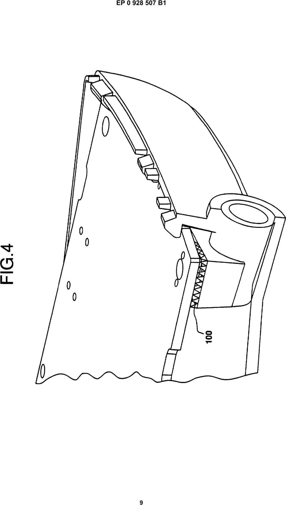
2 1 EP B1 2 Description BACKGROUND OF THE INVENTION Technical Field of the Invention [0001] The present invention relates to antenna connectors, and more particularly, to shielded antenna connectors providing a shield ground and RF connector for interconnections between an antenna and a printed circuit board. Description of Related Art [0002] In the design of cellular telephones, the antenna connector is an essential component. However, the connector happens to be one of the more sensitive areas of the cellular telephone and yields many complex design challenges. Since all transmitted and received signals that the cellular telephone uses must pass through the antenna connection, it is important that the connector function with a minimum of interference. [0003] Presently existing connectors for use with retractable antennas only include an RF connection point for the antenna and provide no ground line or ground shield. When a ground line is required for testing and matching circuitry, an additional coaxial connector must be added to the printed circuit board to provide the necessary test ground. This of course adds to the cost and complexity of the board. An antenna connector incorporating both the ground and RF feed line would be preferred. [0004] U.S. Patent No.,278,70 appears to describe an antenna connector and RF switch assembly for a portable radio. The assembly is used for selectively connecting the radio circuit to the antenna. In the assembly, a switchable conductive center contact portion selectively engages either the antenna or the external signal supply. A molded dielectric insulator portion separates the switchable conductive center contact portion from a metallic housing and is directly connected to the antenna bushing. [000] Early attempts to produce antenna connectors incorporating both ground and RF feed lines, resulted in the ground line acting as a second antenna that received interference signals that disabled the RF feed line. Thus, the connector must be properly shielded in order to avoid this problem. Retractable or telescopic antenna connectors also must provide the ability for a retractable antenna to collapse or pass through the connector. Thus, an RF antenna design providing an RF feed point, proper ground shielding, and capabilities for use with retractable antennas is needed within the cellular telephone industry. SUMMARY OF THE INVENTION [0006] The present invention overcomes the foregoing and other problems with an improved RF antenna connector. The antenna connector includes a metal housing defining a pair of chambers within its interior. The housing acts as a ground shield and surrounds an antenna inserted into a first of these interior chambers. A formed metal contact provides a connection between the RF feed point of the antenna and an RF connector of an associated printed circuit board. The formed metal contact is stapled to an insulating connector that slides within the second interior chamber of the metal housing. Once the connector is inserted within the housing, the metal contact is positioned to engage the RF feed point of an antenna inserted within the first chamber and the RF feed point of a printed circuit board. The metal contact is also positioned such that it is substantially surrounded and shielded by the housing to limit interference from external sources. BRIEF DESCRIPTION OF THE DRAWINGS [0007] For a more complete understanding of the present invention, reference is made to the following detailed description taken in conjunction with the accompanying drawings wherein: FIGURE 1 is a perspective view of the top side of the antenna connector; FIGURE 2 is a perspective view of the bottom side of the antenna connector; FIGURE 3 is a perspective view illustrating an antenna inserted within the antenna connector; FIGURE 4 illustrates the interconnection between the antenna connector and a printed circuit board; and FIGURE is a perspective view illustrating connection of the antenna connector within the housing of a cellular telephone. DETAILED DESCRIPTION OF THE DRAWINGS [0008] Referring now to the Drawings, and more particularly, to FIGURES 1 and 2, there is illustrated the antenna connector of the present invention. The connector consists of the connector housing, insulated connector insert 1 and the shaped metal contact 20. [0009] The connector housing consist of a barrel 2 having a substantially circular cross section for receiving an antenna 27 (FIGURE 3) which is inserted into an antenna chamber 30 within the barrel 2 of housing. The connector housing is preferably cast from a metal such as zinc. The surface of the housing is plated with nickel to prevent oxidation and promote conductivity. The walls of the antenna chamber 30 may threadedly engage the antenna 27 or the antenna can be snapped or soldered into the chamber. The barrel 2 contacts the ground point of an antenna 27 when the antenna is inserted within antenna chamber 30. The barrel 2 of the housing is further configured to ena- 2
![Description of Related Art [0002] In the design of cellular telephones, the antenna connector is an essential component.](/docs-images/51/17633134/images/page_2.jpg "However, the connector happens to be one of the more sensitive areas of the cellular telephone and yields many complex design challenges.")
3 3 EP B ble the antenna 27 inserted within the antenna chamber 30 to retract and extend through the housing. [00] The connector flange 3 extends perpendicularly from the barrel 2 and defines a chamber 40 for receiving the insulated connector insert 1. The chamber 40 defines a pair of opposed slots 4 for engaging the insulated connector insert 1. The base 0 of the connector flange 3 defines an opening through which a portion of the shaped metal contact 20 extends to enable connection with a printed circuit board. The base 0 of connector flange 3 contacts the ground plane of a printed circuit board (PCB) such that the entire housing. acts as a ground shield. The connection between the PCB ground plane and the base 0 of the housing is maintained by a conductive foam 0 which compresses between the board and housing as shown in FIGURE 4. [0011] The insulated connector insert 1 consists of a central body 60 having guide rails 6 extending from the sides thereof. The guide rails 6 engage the opposed slots 4 of the connector flange 3 such that the insulated connector insert 1 may be secured within the antenna housing. The insulated connector insert 1 is molded from plastic, for example, poly-carbonate, and is shaped to receive the shaped metal contact 20 over the central body 60 such that the contact engages the RF feed points of the antenna and a printed circuit board. [0012] The formed metal contact 20 is snapped around the central body 60. The formed metal contact 20 includes an antenna portion 80, base portion 8, and PCB portion 90. The antenna portion 80 angles upward from the insulated connector insert 1 in a v-shape to provide a secure contact with the feed point of an inserted antenna 27. The PCB portion 90 extends slightly outward from the base 0 of the connector flange 3 such that the contact 20 maintains galvanic contact with the PCB RF feed point. The formed metal contact 20 is stapled, soldered or otherwise connected to the insulated connector insert 1 via base portion 8. [0013] Insertion of the combined connector insert 1 and formed metal contact 20 assembly within the chamber 40 positions the formed metal contact 20 such that it is substantially surrounded by the housing of the antenna connector. The housing acts as a ground shield for the antenna connector when it is connected with the ground plane of a PCB. Thus, the RF contact between the antenna and the PCB is shielded from external interference by the barrel 2 of the housing. [0014] The antenna connector is heat staked into a plastic housing of a cellular telephone unit as shown in FIGURE. When the connector is positioned in this manner the PCB portion 90 of the formed metal contact 20 will engage the RF feed of a printed circuit board. Then a PCB board is snapped into place in the telephone housing. [001] Although a preferred embodiment of the method and apparatus of the present invention has been illustrated in the accompanying Drawings and described in the foregoing Detailed Description, it is understood that the invention is not limited to the embodiment disclosed, but is capable of numerous rearrangements, modifications, and substitutions without departing from the scope of the invention as set forth and defined by the following claims. Claims 1. An antenna connector including means (20) for contacting an RF feed point of an antenna (27), the antenna connector characterized by: a metal housing () defining a first interior chamber (30) for receiving an antenna and a second interior chamber (40), the housing acting as a ground shield for the antenna within the first interior chamber; and an insulated insert (1) connected to the means for contacting, the insulated insert configured for insertion into the second interior chamber of the housing such that the means for contacting engages the RF feed point of the antenna within the first chamber. 2. The antenna connector of Claim 1 wherein the housing () substantially surrounds the means (20) for contacting and acts as a ground shield therefore. 3. The antenna connector of Claim 1 wherein the means for contacting further defines means (90) for connecting with an RF feed of a printed circuit board. 4. The antenna connector of Claim 1 wherein the housing further enables extension and retraction of a retractable antenna within the first ihterior chamber (30).. The antenna connector of Claim 1 wherein the first interior chamber (30) threadedly engages the antenna. 6. The antenna connector of Claim 1 wherein the means for contacting comprises a formed metal contact (20). 7. The antenna connection of Claim 6 wherein the insulated insert comprises a plastic connector (60) inserted within the formed metal contact (20). 8. An antenna connector including a formed metal contact (20) for engaging an RF feed point of an antenna (27) and an RF connector of a printed circuit board, the antenna connector characterized 3

4 EP B1 6 by: Patentansprüche a metal housing () defining a first interior chamber (30) for receiving the antenna and a second interior chamber (40), the housing acting as a ground shield for the antenna within the first interior chamber when connected to a ground plane of the printed circuit board; and an insulated connector (1) inserted within the formed metal contact, the connector configured for insertion into the second interior chamber such that the formed metal contact engages the RF feed point of the antenna and is substantially surrounded by the housing to limit interference to the formed metal contact. 9. The antenna connector of Claim 8 wherein the housing () further enables extension and retraction of a retractable antenna within the first interior chamber.. The antenna connector of Claim 8 wherein the first interior chamber (30) threadedly engages the antenna. 11. The antenna connector of Claim 8 wherein the housing () comprises a cast metal conductor. 12. The antenna connector of Claim 11 wherein the metal housing () is plated to prevent oxidation and promote conductivity. 13. An antenna connector including an RF feed connector (20) for contacting an RF feed point of an antenna (27) engaging the antenna connector and a ground connector for engaging a ground plane of a printed circuit board, the antenna characterized by: Antennenverbinder, ein Mittel (20) zum Kontaktieren eines Hochfrequenzspeisepunktes einer Antenne (27) einschließend, gekennzeichnet durch ein eine erste Innenkammer (30) zum Aufnehmen einer Antenne und eine zweite Innenkammer (40) definierendes Metallgehäuse (), das als Masseschirmung für die Antenne in der ersten Innenkammer dient; und einen mit dem Mittel zum Kontaktieren verbundenen isolierten Einsatz (1), konfiguriert zum derartigen Einfügen in die zweite Innenkammer, dass das Mittel zum Kontaktieren mit dem Hochfrequenzspeisepunkt der Antenne in der ersten Kammer in Eingriff kommt. 2. Antennenverbinder nach Anspruch 1, wobei das Gehäuse () im wesentlichen das Mittel (20) zum Kontaktieren umfängt und als Masseschirmung hiervon dient. 3. Antennenverbinder nach Anspruch 1, wobei das Mittel zum Kontaktieren ausserdem ein Mittel zum Verbinden mit einem Hochfrequenzspeisepunkt einer Leiterplatte definiert. 4. Antennenverbinder nach Anspruch 1, wobei das Gehäuse ausserdem das Ausziehen und Einschieben einer einschiebbaren Antenne innerhalb der ersten Innenkammer (30) ermöglicht.. Antennenverbinder nach Anspruch 1, wobei die erste Innenkammer (30) mit der Antenne gewindeartig in Eingriff ist. a metal housing () substantially surrounding the RF feed connector and integral with the ground connector such that the housing forms a ground shield for the RF feed connector and the contacted RF feed point; and an insulated insert (1) connected to the RF feed connector, the insulated insert configured for insertion into the housing. 14. The antenna connector of Claim 13 wherein the metal housing () further comprises means for receiving a retractable antenna. 1. The antenna connector of Claim 13, further including means for insulating the RF feed connector (20) from the ground shield Antennenverbinder nach Anspruch 1, wobei das Mittel zum Kontaktieren einen geformten Metallkontakt (20) umfasst. 7. Antennenverbinder nach Anspruch 6, wobei der isolierte Einsatz einen in den geformten Metallkontakt (20) eingesetzten Plastikverbinder (60) enthält. 8. Antennenverbinder, einen geformten Metallkontakt (20) zum in Eingriff kommen mit einem Hochfrequenzspeisepunkt einer Antenne (27) und einen Hochfrequenzverbinder einer Leiterplatte einschließend, gekennzeichnet durch ein eine erste Innenkammer (30) zum Aufnehmen einer Antenne und eine zweite Innenkammer (40) definierendes Metallgehäuse (), das als Masseschirmung für die Antenne in der 4

5 7 EP B1 8 ersten Innenkammer dient, wenn mit einer Masseplatte der Leiterplatte verbunden; und einen in den geformten Metallkontakt (20) eingesetzten isolierenden Verbinder (1), konfiguriert zum derartigen Einfügen in die zweite Innenkammer, dass der geformte Metallkontakt mit dem Hochfrequenzspeisepunkt der Antenne in Eingriff kommt und von dem Gehäuse im wesentlichen umfangen ist, um Interferenz zu dem geformten Metallkontakt zu begrenzen. 9. Antennenverbinder nach Anspruch 8, wobei das Gehäuse ausserdem das Herausziehen und das Einschieben einer einschiebbaren Antenne innerhalb der ersten Innenkammer ermöglicht.. Antennenverbinder nach Anspruch 8, wobei die erste Innenkammer (30) mit der Antenne gewindeartig in Eingriff ist Revendications 1. Connecteur d'antenne comprenant des moyens (20) destinés à venir en contact avec un point d'alimentation RF d'une antenne (27), le connecteur d'antenne étant caractérisé par : un boîtier en métal () définissant une première chambre intérieure (30) pour recevoir une antenne et une seconde chambre intérieure (40), le boîtier agissant comme un blindage de masse pour l'antenne à l'intérieur de la première chambre intérieure ; et un insert isolé (1) connecté aux moyens de contact, l'insert isolé étant configuré pour l'insertion dans la seconde chambre intérieure du boîtier, de façon que les moyens de contact viennent en contact avec le point d'alimentation RF de l'antenne à l'intérieur de la première chambre. 11. Antennenverbinder nach Anspruch 8, wobei das Gehäuse einen Metallgussleiter umfasst. 12. Antennenverbinder nach Anspruch 11, wobei das Metallgehäuse metallbeschichtet ist, um Oxidation zu verhindern und Leitfähigkeit zu unterstützen. 13. Antennenverbinder, einen Hochfrequenzspeiseverbinder (20) zum Kontaktieren eines Hochfrequenzspeisepunktes einer mit dem Antennenverbinder in Eingriff stehenden Antenne (27) und einen Masseverbinder zum in Eingriff stehen mit einer Masseplatte einer Leiterplatte enthaltend, gekennzeichnet durch ein den Hochfrequenzspeiseverbinder im wesentlichen umfangendes Metallgehäuse (), das mit dem Masseverbinder derart eine Einheit bildet, dass das Gehäuse eine Masseschirmung für den Hochfrequenzspeiseverbinder und den kontaktierten Hochfrequenzspeisepunkt bildet; und einen mit dem Hochfrequenzspeiseverbinder verbundenen isolierten Einsatz (1), konfiguriert zum Einfügen in das Gehäuse. 14. Antennenverbinder nach Anspruch 13, wobei das Metallgehäuse () ausserdem Mittel zum Aufnehmen einer einschiebbaren Antenne umfasst. 1. Antennenverbinder nach Anspruch 13, ausserdem Mittel zum Isolieren des Hochfrequenzspeiseverbinders (20) von der Masseschirmung enthaltend Connecteur d'antenne selon la revendication 1, dans lequel le boîtier () entoure pratiquement les moyens de contact (20) et agit comme un blindage de masse pour ceux-ci. 3. Connecteur d'antenne selon la revendication 1, dans lequel les moyens de contact définissent en outre des moyens (90) pour la connexion à une source d'alimentation RF d'une carte de circuit imprimé. 4. Connecteur d'antenne selon la revendication 1, dans lequel le boîtier permet en outre d'étendre et de rétracter une antenne rétractable à l'intérieur de la première chambre intérieure (30).. Connecteur d'antenne selon la revendication 1, dans lequel la première chambre intérieure (30) est accouplée à l'antenne par vissage. 6. Connecteur d'antenne selon la revendication 1, dans lequel les moyens de contact comprennent un contact en métal (20) mis en forme. 7. Connecteur d'antenne selon la revendication 6, dans lequel l'insert isolé comprend un connecteur en matière plastique (60) inséré à l'intérieur du contact en métal (20) mis en forme. 8. Connecteur d'antenne comprenant un contact en métal (20) mis en forme pour venir en contact avec un point d'alimentation RF d'une antenne (27) et avec un connecteur RF d'une carte de circuit imprimé, le connecteur d'antenne étant caractérisé par : un boîtier en métal () définissant une premiè-

6 9 EP B1 re chambre intérieure (30) pour recevoir l'antenne et une seconde chambre intérieure (40), le boîtier agissant comme un blindage de masse pour l'antenne à l'intérieur de la première chambre intérieure, lorsqu'il est connecté à un plan de masse de la carte de circuit imprimé; et un connecteur isolé (1) inséré à l'intérieur du contact en métal mis en forme, le connecteur étant configuré pour l'insertion dans la seconde chambre intérieure, de façon que le contact en métal mis en forme vienne en contact avec le point d'alimentation RF de l'antenne et soit pratiquement entouré par le boîtier, pour limiter le brouillage atteignant le contact en métal mis en forme. 1 comprenant en outre des moyens pour isoler le connecteur d'alimentation RF (20) vis-à-vis du blindage de masse. 9. Connecteur d'antenne selon la revendication 8, dans lequel le boîtier () permet en outre d'étendre et de rétracter une antenne rétractable à l'intérieur de la première chambre intérieure. 20. Connecteur d'antenne selon la revendication 8, dans lequel la première chambre intérieure (30) est accouplée à l'antenne par vissage. 11. Connecteur d'antenne selon la revendication 8, dans lequel le boîtier () comprend un conducteur en métal moulé Connecteur d'antenne selon la revendication 11, dans lequel le boîtier en métal () est revêtu pour empêcher l'oxydation et favoriser la conductivité Connecteur d'antenne comprenant un connecteur d'alimentation RF (20) pour venir en contact avec un point d'alimentation RF d'une antenne (27) qui est accouplée au connecteur d'antenne, et un connecteur de masse pour venir en contact avec un plan de masse d'une carte de circuit imprimé, l'antenne étant caractérisée par : 3 40 un boîtier en métal () entourant pratiquement le connecteur d'alimentation RF et formé en une seule pièce avec le connecteur de masse, de façon que le boîtier forme un blindage de masse pour le connecteur d'alimentation RF et le point d'alimentation RF avec lequel un contact est établi; et un insert isolé (1) connecté au connecteur d'alimentation RF, l'insert isolé étant configuré pour l'insertion dans le boîtier Connecteur d'antenne selon la revendication 13, dans lequel le boîtier en métal () comprend en outre des moyens pour recevoir une antenne rétractable. 1. Connecteur d'antenne selon la revendication 13, 6

7 EP B1 7

8 EP B1 8

9 EP B1 9
10 EP B1

(51) Int Cl. 7 : H05K 1/18
 Int Cl. 7 : H05K 1/18") (19) Europäisches Patentamt European Patent Office Office européen des brevets *EP000888036B1* (11) EP 0 888 036 B1 (12) EUROPEAN PATENT SPECIFICATION (4) Date of publication and mention of the grant of
(19) Europäisches Patentamt European Patent Office Office européen des brevets *EP000888036B1* (11) EP 0 888 036 B1 (12) EUROPEAN PATENT SPECIFICATION (4) Date of publication and mention of the grant of
VGM. VGM information. HAMBURG SÜD VGM WEB PORTAL - USER GUIDE June 2016
 Overview The Hamburg Süd VGM-Portal is an application which enables to submit VGM information directly to Hamburg Süd via our e-portal web page. You can choose to insert VGM information directly, or download
USBASIC SAFETY IN NUMBERS
 USBASIC SAFETY IN NUMBERS #1.Current Normalisation Ropes Courses and Ropes Course Elements can conform to one or more of the following European Norms: -EN 362 Carabiner Norm -EN 795B Connector Norm -EN
p^db=`oj===pìééçêíáåñçêã~íáçå=
 p^db=`oj===pìééçêíáåñçêã~íáçå= Error: "Could not connect to the SQL Server Instance" or "Failed to open a connection to the database." When you attempt to launch ACT! by Sage or ACT by Sage Premium for
PROFIBUS-DP Repeater 1 to 1 and 1 to 5 with optional level converter module
 LSS PROFIBUS-DP Repeater 1 to 1 and 1 to 5 with optional level converter module The LSS PROFIBUS-DP repeaters 1 to 1 and 1 to 5 are used for coupling up to six PROFIBUS bus segments in RS 485 bus technology.
AKTIVE DVB-T ZIMMERANTENNE ANSCHLUSSHINWEISE ACTIVE DVB-T INDOOR ANTENNA CONNECTION INSTRUCTIONS
 K la vi er l ac ko p tik AKTIVE DVB-T ZIMMERANTENNE ANSCHLUSSHINWEISE ACTIVE DVB-T INDOOR ANTENNA CONNECTION INSTRUCTIONS ZA 8970 DRUCKS0682.indd 1 05.09.12 15:15 VerpAckunGsinhAlT UKW / UHF / VHF Flachantenne
TEPZZ Z4Z4 4B_T EP B1 (19) (11) EP B1 (12) EUROPEAN PATENT SPECIFICATION
 (11) EP B1 (12) EUROPEAN PATENT SPECIFICATION") (19) TEPZZ Z4Z4 4B_T (11) EP 2 0 424 B1 (12) EUROPEAN PATENT SPECIFICATION (4) Date of publication and mention of the grant of the patent:.07.14 Bulletin 14/31 (21) Application number: 08168678.4 (1) Int
(19) TEPZZ Z4Z4 4B_T (11) EP 2 0 424 B1 (12) EUROPEAN PATENT SPECIFICATION (4) Date of publication and mention of the grant of the patent:.07.14 Bulletin 14/31 (21) Application number: 08168678.4 (1) Int
(51) Int Cl.: H02K 11/02 (2006.01) H02K 5/22 (2006.01)
 Int Cl.: H02K 11/02 (2006.01) H02K 5/22 (2006.01)") (19) (11) EP 1 62 62 B1 (12) EUROPEAN PATENT SPECIFICATION (4) Date of publication and mention of the grant of the patent: 1..2008 Bulletin 2008/42 (21) Application number: 0470369. (22) Date of filing:
(19) (11) EP 1 62 62 B1 (12) EUROPEAN PATENT SPECIFICATION (4) Date of publication and mention of the grant of the patent: 1..2008 Bulletin 2008/42 (21) Application number: 0470369. (22) Date of filing:
EP 0 444 396 B2 (19) (11) EP 0 444 396 B2 (12) NEUE EUROPÄISCHE PATENTSCHRIFT
 (11) EP 0 444 396 B2 (12) NEUE EUROPÄISCHE PATENTSCHRIFT") (19) Europäisches Patentamt European Patent Office Office européen des brevets (11) EP 0 444 396 B2 (12) NEUE EUROPÄISCHE PATENTSCHRIFT (4) Veröffentlichungstag und Bekanntmachung des Hinweises auf die
(19) Europäisches Patentamt European Patent Office Office européen des brevets (11) EP 0 444 396 B2 (12) NEUE EUROPÄISCHE PATENTSCHRIFT (4) Veröffentlichungstag und Bekanntmachung des Hinweises auf die
Entwurf. preliminary
 KAPRi plus Erweiterungsset M12 KAPRi plus Extension Kit M12 KAPRi plus Kit d Extension M12 Bedienungsanleitung / User instructions / Instructions d installation 899366 KAPRi plus Erweiterungsset M12 /
Kurzanleitung um Transponder mit einem scemtec TT Reader und der Software UniDemo zu lesen
 Kurzanleitung um Transponder mit einem scemtec TT Reader und der Software UniDemo zu lesen QuickStart Guide to read a transponder with a scemtec TT reader and software UniDemo Voraussetzung: - PC mit der
CABLE TESTER. Manual DN-14003
 CABLE TESTER Manual DN-14003 Note: Please read and learn safety instructions before use or maintain the equipment This cable tester can t test any electrified product. 9V reduplicated battery is used in
eurex rundschreiben 094/10
 eurex rundschreiben 094/10 Datum: Frankfurt, 21. Mai 2010 Empfänger: Alle Handelsteilnehmer der Eurex Deutschland und Eurex Zürich sowie Vendoren Autorisiert von: Jürg Spillmann Weitere Informationen zur
Number of Maximal Partial Clones
 Number of Maximal Partial Clones KARSTEN SCHÖLZEL Universität Rostoc, Institut für Mathemati 26th May 2010 c 2010 UNIVERSITÄT ROSTOCK MATHEMATISCH-NATURWISSENSCHAFTLICHE FAKULTÄT, INSTITUT FÜR MATHEMATIK
S-Digicash Payez mobile depuis votre compte courant! Mobil bezahlen, direkt von Ihrem Girokonto aus! Pay mobile from your current account!
 S-Digicash Payez mobile depuis votre compte courant! Mobil bezahlen, direkt von Ihrem Girokonto aus! Pay mobile from your current account! Payez mobile depuis votre compte courant BCEE! Scannez le QR Code
Electrical tests on Bosch unit injectors
 Valid for Bosch unit injectors with order numbers 0 414 700 / 0 414 701 / 0 414 702 Parts Kit Magnet*: - F00H.N37.925 - F00H.N37.933 - F00H.N37.934 * For allocation to the 10-place Bosch order number,
11 EN 81-70 Page 1 of 2 Standard: INTERPRETATION RELATED TO. Clause(s): 5.4.2.3
: 5.4.2.3") CEN RELATED TO 11 Page 1 of 2 Standard: Edition: 2003 Clause(s): 5.4.2.3 Valid from: 15/09/2010 Date of modification: Key-word(s): Car operating panel, Two entrance lift Replacing interpretation No.: QUESTION
CEN RELATED TO 11 Page 1 of 2 Standard: Edition: 2003 Clause(s): 5.4.2.3 Valid from: 15/09/2010 Date of modification: Key-word(s): Car operating panel, Two entrance lift Replacing interpretation No.: QUESTION
Patentrelevante Aspekte der GPLv2/LGPLv2
 Patentrelevante Aspekte der GPLv2/LGPLv2 von RA Dr. Till Jaeger OSADL Seminar on Software Patents and Open Source Licensing, Berlin, 6./7. November 2008 Agenda 1. Regelungen der GPLv2 zu Patenten 2. Implizite
VGM. VGM information. HAMBURG SÜD VGM WEB PORTAL USER GUIDE June 2016
 Overview The Hamburg Süd VGM Web portal is an application that enables you to submit VGM information directly to Hamburg Süd via our e-portal Web page. You can choose to enter VGM information directly,
Notice: All mentioned inventors have to sign the Report of Invention (see page 3)!!!
!!!") REPORT OF INVENTION Please send a copy to An die Abteilung Technologietransfer der Universität/Hochschule An die Technologie-Lizenz-Büro (TLB) der Baden-Württembergischen Hochschulen GmbH Ettlinger Straße
REPORT OF INVENTION Please send a copy to An die Abteilung Technologietransfer der Universität/Hochschule An die Technologie-Lizenz-Büro (TLB) der Baden-Württembergischen Hochschulen GmbH Ettlinger Straße
Hazards and measures against hazards by implementation of safe pneumatic circuits
 Application of EN ISO 13849-1 in electro-pneumatic control systems Hazards and measures against hazards by implementation of safe pneumatic circuits These examples of switching circuits are offered free
Anwendungsbeispiele Verstärker Application Examples Amplifiers
 Anwendungsbeispiele Verstärker Application Examples Amplifiers Anwendungsbeispiele Application examples Multimedia-Verteilung in Sternstruktur über Abzweiger Multimedia distribution in star structure
Snap-in switch for switches PSE, MSM and MCS 30
 Product manual Snap-in switch for switches PSE, MSM and MCS 30 CONTENTS 1. PRODUCT DESCRIPTION 2. DATA AND DIMENSIONAL DRAWINGS 2.1. Technical Data 2.2. Dimensions of PSE with a Mounting Diameter 19 mm
ZERTIFIKAT. Rohrwerk Maxhütte GmbH ISO 9001:2008. Die Zertifizierungsstelle der TÜV SÜD Management Service GmbH bescheinigt, dass das Unternehmen
 ZERTIFIKAT Die Zertifizierungsstelle der TÜV SÜD Management Service GmbH bescheinigt, dass das Unternehmen Franz-Kunze-Straße 1 Deutschland für den Geltungsbereich Produktion von nahtlosen warmgewalzten,
Release Notes BRICKware 7.5.4. Copyright 23. March 2010 Funkwerk Enterprise Communications GmbH Version 1.0
 Release Notes BRICKware 7.5.4 Copyright 23. March 2010 Funkwerk Enterprise Communications GmbH Version 1.0 Purpose This document describes new features, changes, and solved problems of BRICKware 7.5.4.
CB RADIO Service Manual AE 6890
 CB RADIO Service Manual AE 6890 Downloaded from www.cbradio.nl Technische Mitteilung zu AE 6890 Problem: Bei Montage einer schlecht geerdeten Antenne oder einer Antenne mit schlechtem SWR sehr nahe am
Titelbild1 ANSYS. Customer Portal LogIn
 Titelbild1 ANSYS Customer Portal LogIn 1 Neuanmeldung Neuanmeldung: Bitte Not yet a member anklicken Adressen-Check Adressdaten eintragen Customer No. ist hier bereits erforderlich HERE - Button Hier nochmal
NEWSLETTER. FileDirector Version 2.5 Novelties. Filing system designer. Filing system in WinClient
 Filing system designer FileDirector Version 2.5 Novelties FileDirector offers an easy way to design the filing system in WinClient. The filing system provides an Explorer-like structure in WinClient. The
PELTIER-HOCHLEISTUNGSMODULE
 Wolfgang Knap Gesellschaft m.b.h. & Co.KG A-113 Wien Lilienberggasse 13 Tel.: +43-1-43 8 12 Fax: +43-1-48 72 13 e-mail: info@knap.at http://www.knap.at PELTIER-HOCHLEISTUNGSMODULE Die Hochleistungsmodule
C 146 EMV Gehäuse/EMC Housings
 146 EMV Gehäuse/EM Housings Für Serien 146 E 6-24 pol 146 D 4-64 pol 146 M 2-7 Module 146 HSE 6 pol For series 146 E 6-24 contacts 146 D 4-64 contacts 146 M 2-7 Module 146 HSE 6 contacts mphenol 151 146
KURZANLEITUNG. Firmware-Upgrade: Wie geht das eigentlich?
 KURZANLEITUNG Firmware-Upgrade: Wie geht das eigentlich? Die Firmware ist eine Software, die auf der IP-Kamera installiert ist und alle Funktionen des Gerätes steuert. Nach dem Firmware-Update stehen Ihnen
fischerwerke GmbH & Co. KG Geltungsbereich: Entwicklung, Produktion und Vertrieb von Kunststoff-, Metall- und chemischen Befestigungssystemen
 ZERTIFIKAT Hiermit wird bescheinigt, dass mit den im Anhang gelisteten Standorten ein Umweltmanagementsystem eingeführt hat und anwendet. Geltungsbereich: Entwicklung, Produktion und Vertrieb von Kunststoff-,
Umschaltadapter/ Changeover / Trennadapter Disconnection Adapter für LSA-PLUS NT for LSA-PLUS NT. Montageanweisung Mounting Instructions
 Umschaltadapter/ Changeover / Trennadapter Disconnection Adapter für LSA-PLUS NT for LSA-PLUS NT Montageanweisung Mounting Instructions Der Umschalter dient zum unterbrechungsfreien Umschalten von Installations-drähten
VIDEO CALL CAMERA G-VCAM-01
 VIDEO CALL CAMERA G-VCAM-01 EN AUS GUTEM GRUND ENGLISH 07-10 2 SAFETY AND INFORMATION Safety 7 This camera is designed to transmit video and audio signals. All other uses are expressly prohibited. 7 Protect
Electrical testing of Bosch common rail piezo injectors
 Applies to generation CRI 3: Bosch 10-position order number 0 445 115 = CRI 3-16 (CRI 3.0) 1600 bar 0 445 116 = CRI 3-18 (CRI 3.2) 1800 bar 0 445 117 = CRI 3-20 (CRI 3.3) 2000 bar Tools required: Hybrid
Electrical testing of Bosch common rail Injectors
 Electrical testing of Bosch common rail Injectors Contents: 1. Adapter cable for Hybridtester FSA 050 (article number 0 684 010 050 / 1 687 023 571) 2. Electrical testing of Bosch common rail solenoid
RS232-Verbindung, RXU10 Herstellen einer RS232-Verbindung zwischen PC und Messgerät oder Modem und Messgerät
 Betriebsanleitung RS232-Verbindung, RXU10 Herstellen einer RS232-Verbindung zwischen PC und Messgerät oder Modem und Messgerät ä 2 Operating Instructions RS232 Connection, RXU10 Setting up an RS232 connection
FEM Isoparametric Concept
 FEM Isoparametric Concept home/lehre/vl-mhs--e/folien/vorlesung/4_fem_isopara/cover_sheet.tex page of 25. p./25 Table of contents. Interpolation Functions for the Finite Elements 2. Finite Element Types
Honeywell AG Hardhofweg. D-74821 Mosbach MU1H-1220GE23 R1001
 BA 95 Einbau-Anleitung Installation Instructions Einbau Installation Einbaubeispiel Installation example Ablaufleitung vorsehen Install discharge pipework Durchflussrichtung beachten! Consider direction
Verarbeitungsspezifikation Application Specification. Verarbeitungsspezifikation. Application Specification MA-59V093. für for. Winkelstecker für PCB
 Verarbeitungsspezifikation MA-59V093 für for Winkelstecker für PCB Right angle plug for PCB 59S2AF-40MXX-Y 59S2LF-40MXX-Y 59S2RF-40MXX-Y 59S2UF-40MXX-Y 200 09-0100 U_Winkler 11.02.09 100 08-v323 U_Winkler
1. General information... 2 2. Login... 2 3. Home... 3 4. Current applications... 3
 User Manual for Marketing Authorisation and Lifecycle Management of Medicines Inhalt: User Manual for Marketing Authorisation and Lifecycle Management of Medicines... 1 1. General information... 2 2. Login...
UWC 8801 / 8802 / 8803
 Wandbedieneinheit Wall Panel UWC 8801 / 8802 / 8803 Bedienungsanleitung User Manual BDA V130601DE UWC 8801 Wandbedieneinheit Anschluss Vor dem Anschluss ist der UMM 8800 unbedingt auszuschalten. Die Übertragung
Level 2 German, 2015
 91126 911260 2SUPERVISOR S Level 2 German, 2015 91126 Demonstrate understanding of a variety of written and / or visual German text(s) on familiar matters 2.00 p.m. Friday 4 December 2015 Credits: Five
Weather forecast in Accra
 Weather forecast in Accra Thursday Friday Saturday Sunday 30 C 31 C 29 C 28 C f = 9 5 c + 32 Temperature in Fahrenheit Temperature in Celsius 2 Converting Celsius to Fahrenheit f = 9 5 c + 32 tempc = 21
Magic Figures. We note that in the example magic square the numbers 1 9 are used. All three rows (columns) have equal sum, called the magic number.
 have equal sum, called the magic number.") Magic Figures Introduction: This lesson builds on ideas from Magic Squares. Students are introduced to a wider collection of Magic Figures and consider constraints on the Magic Number associated with such
Magic Figures Introduction: This lesson builds on ideas from Magic Squares. Students are introduced to a wider collection of Magic Figures and consider constraints on the Magic Number associated with such
Parameter-Updatesoftware PF-12 Plus
 Parameter-Updatesoftware PF-12 Plus Mai / May 2015 Inhalt 1. Durchführung des Parameter-Updates... 2 2. Kontakt... 6 Content 1. Performance of the parameter-update... 4 2. Contact... 6 1. Durchführung
Aufbau eines IT-Servicekataloges am Fallbeispiel einer Schweizer Bank
 SwissICT 2011 am Fallbeispiel einer Schweizer Bank Fritz Kleiner, fritz.kleiner@futureways.ch future ways Agenda Begriffsklärung Funktionen und Aspekte eines IT-Servicekataloges Fallbeispiel eines IT-Servicekataloges
roll-up SONJA powerdisplays Aufbauanleitung Assemble instructions
 powerdisplay SONJA Mit Rollfunktion! Die Werbefläche rollt sich vollständig in das Display. So ist Ihre Werbung geschützt und in Sekunden wieder aufgebaut. Farbe: chrom/silber inkl. Tasche With rolling
CA_MESSAGES_ORS_HDTV_IRD_GUIDELINE
 CA_MESSAGES_ORS_HDTV_IRD_GUIDELINE 1/11 ORS NOTICE This document is property of Österreichische Rundfunksender GmbH & Co. KG, hereafter ORS, and may not be reproduced, modified and/or diffused in any way
CA_MESSAGES_ORS_HDTV_IRD_GUIDELINE
 CA_MESSAGES_ORS_HDTV_IRD_GUIDELINE Version 1.1 02.05.2017 1/10 ORS NOTICE This document is property of Österreichische Rundfunksender GmbH & Co. KG, hereafter ORS, and may not be reproduced, modified and/or
(51) Int Cl.: H04L 12/28 (2006.01) H04L 29/06 (2006.01)
 Int Cl.: H04L 12/28 (2006.01) H04L 29/06 (2006.01)") (19) Europäisches Patentamt European Patent Office Office européen des brevets (12) EUROPEAN PATENT SPECIFICATION (11) EP 1 382 161 B1 (4) Date of publication and mention of the grant of the patent: 04.01.06
(19) Europäisches Patentamt European Patent Office Office européen des brevets (12) EUROPEAN PATENT SPECIFICATION (11) EP 1 382 161 B1 (4) Date of publication and mention of the grant of the patent: 04.01.06
Cloud for Customer Learning Resources. Customer
 Cloud for Customer Learning Resources Customer Business Center Logon to Business Center for Cloud Solutions from SAP & choose Cloud for Customer https://www.sme.sap.com/irj/sme/ 2013 SAP AG or an SAP affiliate
SYSTEM COMPONENTS FOR 3~ RECESSED TRACK STANDARD 3~ RECESSED TRACK STANDARD. 3~ Recessed Track Standard
 3~ RECESSED TRACK STANDARD Ceiling cut 40 59 3~ Recessed Track Standard 41 A 5-conductor recessed track with 3 separately switchable circuits and a data bus track. It consists of an extruded aluminum profile
Word-CRM-Upload-Button. User manual
 Word-CRM-Upload-Button User manual Word-CRM-Upload for MS CRM 2011 Content 1. Preface... 3 2. Installation... 4 2.1. Requirements... 4 2.1.1. Clients... 4 2.2. Installation guidelines... 5 2.2.1. Client...
Geometrie und Bedeutung: Kap 5
 : Kap 5 21. November 2011 Übersicht Der Begriff des Vektors Ähnlichkeits Distanzfunktionen für Vektoren Skalarprodukt Eukidische Distanz im R n What are vectors I Domininic: Maryl: Dollar Po Euro Yen 6
Invitation - Benutzerhandbuch. User Manual. User Manual. I. Deutsch 2. 1. Produktübersicht 2. 1.1. Beschreibung... 2
 Invitation - Inhaltsverzeichnis I. Deutsch 2 1. Produktübersicht 2 1.1. Beschreibung......................................... 2 2. Installation und Konfiguration 2 2.1. Installation...........................................
iid software tools QuickStartGuide iid USB base driver installation
 iid software tools QuickStartGuide iid software tools USB base driver installation microsensys Nov 2016 Introduction / Einleitung This document describes in short form installation of the microsensys USB
Where are we now? The administration building M 3. Voransicht
 Let me show you around 9 von 26 Where are we now? The administration building M 3 12 von 26 Let me show you around Presenting your company 2 I M 5 Prepositions of place and movement There are many prepositions
Ein Stern in dunkler Nacht Die schoensten Weihnachtsgeschichten. Click here if your download doesn"t start automatically
 Ein Stern in dunkler Nacht Die schoensten Weihnachtsgeschichten Click here if your download doesn"t start automatically Ein Stern in dunkler Nacht Die schoensten Weihnachtsgeschichten Ein Stern in dunkler
MINI 1-Conductor/1-Pin Receptacle Terminal Blocks; 2-Conductor/2-Pin Receptacle Terminal Blocks, Series 2020
 X-COM @-SYSTEM MINI 1-Conductor/1-Pin Receptacle Terminal Blocks; 2-Conductor/2-Pin Receptacle Terminal Blocks, Series 2020 0.14 1 (1.5) mm 2 AWG 24 16 500 V/6 kv/3 1 13.5 A* 0.14 1 (1.5) mm 2 AWG 24 16
CA_MESSAGES_ORS_HDTV_IRD_GUIDELINE
 CA_MESSAGES_ORS_HDTV_IRD_GUIDELINE 1/8 ORS NOTICE This document is property of Österreichische Rundfunksender GmbH & Co. KG, hereafter ORS, and may not be reproduced, modified and/or diffused in any way
Lukas Hydraulik GmbH Weinstraße 39 D Erlangen. Mr. Sauerbier. Lukas Hydraulik GmbH Weinstraße 39 D Erlangen. edraulic rescue equipment
 Technical Report No. 028-7130 95685-050 of 22.02.2017 Client: Lukas Hydraulik GmbH Weinstraße 39 D-91058 Erlangen Mr. Sauerbier Manufacturing location: Lukas Hydraulik GmbH Weinstraße 39 D-91058 Erlangen
miditech 4merge 4-fach MIDI Merger mit :
 miditech 4merge 4-fach MIDI Merger mit : 4 x MIDI Input Port, 4 LEDs für MIDI In Signale 1 x MIDI Output Port MIDI USB Port, auch für USB Power Adapter Power LED und LOGO LEDs Hochwertiges Aluminium Gehäuse
(51) Int Cl.: G01N 30/20 (2006.01)
 Int Cl.: G01N 30/20 (2006.01)") (19) (11) EP 1 336 100 B1 (12) EUROPÄISCHE PATENTSCHRIFT (4) Veröffentlichungstag und Bekanntmachung des Hinweises auf die Patenterteilung: 21.01.2009 Patentblatt 2009/04 (21) Anmeldenummer: 0198010.9
(19) (11) EP 1 336 100 B1 (12) EUROPÄISCHE PATENTSCHRIFT (4) Veröffentlichungstag und Bekanntmachung des Hinweises auf die Patenterteilung: 21.01.2009 Patentblatt 2009/04 (21) Anmeldenummer: 0198010.9
Registration of residence at Citizens Office (Bürgerbüro)
") Registration of residence at Citizens Office (Bürgerbüro) Opening times in the Citizens Office (Bürgerbüro): Monday to Friday 08.30 am 12.30 pm Thursday 14.00 pm 17.00 pm or by appointment via the Citizens
Registration of residence at Citizens Office (Bürgerbüro) Opening times in the Citizens Office (Bürgerbüro): Monday to Friday 08.30 am 12.30 pm Thursday 14.00 pm 17.00 pm or by appointment via the Citizens
v+s Output Quelle: Schotter, Microeconomics, , S. 412f
 The marginal cost function for a capacity-constrained firm At output levels that are lower than the firm s installed capacity of K, the marginal cost is merely the variable marginal cost of v. At higher
Zubehör Accessories Accessoires
 Seite Page Page 14/2 DA 14/4 Allgemeine Merkmale Drehantrieb General parameters Rotary drive unit Caractéristiques générales Servomoteur rotatif + 16 Zubehör Accessories Accessoires 14/0 Drehantrieb Rotary
Exercise (Part II) Anastasia Mochalova, Lehrstuhl für ABWL und Wirtschaftsinformatik, Kath. Universität Eichstätt-Ingolstadt 1
 Anastasia Mochalova, Lehrstuhl für ABWL und Wirtschaftsinformatik, Kath. Universität Eichstätt-Ingolstadt 1") Exercise (Part II) Notes: The exercise is based on Microsoft Dynamics CRM Online. For all screenshots: Copyright Microsoft Corporation. The sign ## is you personal number to be used in all exercises. All
Exercise (Part II) Notes: The exercise is based on Microsoft Dynamics CRM Online. For all screenshots: Copyright Microsoft Corporation. The sign ## is you personal number to be used in all exercises. All
DIN-Rundsteckverbinder DIN circular connectors Connecteurs circulaires DIN
 0103 DIN-Einbaukupplung, geschirmt, mit Verriegelung, Metallgehäuse, Flansch und Lötanschlüssen Kontaktträger, V0 nach UL 94 Kontaktfeder Massekontaktfeder Cu, vernickelt DIN-Steckern 0131, 0137, S, XS
Aufgabenstellung Mit welchen SICLOCK Produkten kann ich einen PC Zeitsynchronisieren?
 SICLOCK Application Note AN-0005 Titel Synchronisation von PCs mit SICLOCK Aufgabenstellung Mit welchen SICLOCK Produkten kann ich einen PC Zeitsynchronisieren? Schlüsselwörter SICLOCK DCFRS, WinGPS, GPS1000,
Electrical testing of Bosch common rail solenoid valve (MV) injectors
 injectors") Applies to MV injector, generation: -CRI 1.0 / 2.0 / 2.1 / 2.2 -CRIN 1 / 2 / 3, with K oder AK plug Bosch 10-position order number Bosch-Bestellnummer CRI: 0 445 110 xxx Bosch-Bestellnummer CRIN: 0 445
Applies to MV injector, generation: -CRI 1.0 / 2.0 / 2.1 / 2.2 -CRIN 1 / 2 / 3, with K oder AK plug Bosch 10-position order number Bosch-Bestellnummer CRI: 0 445 110 xxx Bosch-Bestellnummer CRIN: 0 445
prorm Budget Planning promx GmbH Nordring Nuremberg
 prorm Budget Planning Budget Planning Business promx GmbH Nordring 100 909 Nuremberg E-Mail: support@promx.net Content WHAT IS THE prorm BUDGET PLANNING? prorm Budget Planning Overview THE ADVANTAGES OF
Tube Analyzer LogViewer 2.3
 Tube Analyzer LogViewer 2.3 User Manual Stand: 25.9.2015 Seite 1 von 11 Name Company Date Designed by WKS 28.02.2013 1 st Checker 2 nd Checker Version history Version Author Changes Date 1.0 Created 19.06.2015
Zubehör für mehrpolige Steckverbinder
 für mehrpolige Steckverbinder Einfache Codierstifte für Codierungen Codierung mit einfachem Codierstift einfache Codierstifte aus Edelstahl aus Stahl, verzinkt (nicht für MIXO Einsätze) CR 20 CR 20 D einfache
(51) Int Cl.: H01C 1/14 (2006.01) H01C 1/144 (2006.01) H01C 17/28 (2006.01)
 Int Cl.: H01C 1/14 (2006.01) H01C 1/144 (2006.01) H01C 17/28 (2006.01)") (19) TEPZZ 8_ 9_B_T (11) EP 2 281 291 B1 (12) EUROPEAN PATENT SPECIFICATION (4) Date of publication and mention of the grant of the patent: 01.07.201 Bulletin 201/27 (21) Application number: 0873042.3
(19) TEPZZ 8_ 9_B_T (11) EP 2 281 291 B1 (12) EUROPEAN PATENT SPECIFICATION (4) Date of publication and mention of the grant of the patent: 01.07.201 Bulletin 201/27 (21) Application number: 0873042.3
Installation Instructions
 EN DE Installation Instructions WLAN Installation Kit, 300 Mbps, 5 GHz, 16 dbi AK-4 Wireless Kit Scope of delivery Junction box AK-4 (1x) 1 Connection board AK-4 CB with 12VDC power supply unit (1x) 2
Kuhnke Technical Data. Contact Details
 Kuhnke Technical Data The following page(s) are extracted from multi-page Kuhnke product catalogues or CDROMs and any page number shown is relevant to the original document. The PDF sheets here may have
Power supply Interference suppressed acc. to DIN EN /- 4, EN 55011, EN CI. B, power factor corrected Power factor BöSha LED driver
 Operating Instructions LED Mast Double Luminaire Callisto SC DB, incl. Inclination Adjustment, Single-Chip Technology (Please, read carefully before starting operation) Version: 16.01.2017 Model 369-M
Level 2 German, 2013
 91126 911260 2SUPERVISOR S Level 2 German, 2013 91126 Demonstrate understanding of a variety of written and / or visual German text(s) on familiar matters 9.30 am Monday 11 November 2013 Credits: Five
Building Instructions. Aufbauanleitung. Service-Hotline:
 86488-2006 02.02.2012 Aufbauanleitung Building Instructions Service-Hotline:+49 421 38693 33 86488-2006 Vergleichen Sie zuerst die Materialliste mit Ihrem Paketinhalt! Bitte haben Sie Verständnis, daß
Martin Luther. Click here if your download doesn"t start automatically
 Die schönsten Kirchenlieder von Luther (Vollständige Ausgabe): Gesammelte Gedichte: Ach Gott, vom Himmel sieh darein + Nun bitten wir den Heiligen Geist... der Unweisen Mund... (German Edition) Martin
Produktinformation Access Upgrade Video. Product information Access licence for video upgrade AUV 870-0 T AUV 870-0 F
 Produktinformation Access Upgrade Video Product information Access licence for video upgrade AUV 870-0 T AUV 870-0 F 1+2 100-1216 V1.1.2 1216-11-1159 MAC-Adresse D4-E3-2C-XX-XX-XX 3+4 press click 2 5 6
Electromagnetic Flowmeter FXE4000-DE43F
 Pos: 2 /Grid-Layout/Titelblätter/Ersatzteilblätter/Durchfluss/FXE4000-DE43F @ 65\mod_1350460748604_3101.docx @ 523546 @ @ 1 === Ende der Liste für Textmarke Cover === Spare Parts List SPL/FXE4000-DE43F-EN
Datenblatt. P-series PDU 2.5/4/4AN
 Turn five into three that's the winning formula of the new P series with the PUSH IN connection system in which the pitches for 2.5, 4, 6 and 10 mm² are each combined in one terminal block. That means
Hinweisblatt. Für den Einsatz des MAX! Heizungssteuerungssystems haben Sie zwei Alternativen: Die MAX! Einzelraumlösung und die MAX! Hauslösung.
 Hinweisblatt MAX! Heizkörperthermostat BC-RT-TRX-CyG Art.-Nr. 99017 MAX! Fensterkontakt BC-SC-Rd-WM Art.-Nr. 99023 Für den Einsatz des MAX! Heizungssteuerungssystems haben Sie zwei Alternativen: Die MAX!
EEX Kundeninformation 2007-09-05
 EEX Eurex Release 10.0: Dokumentation Windows Server 2003 auf Workstations; Windows Server 2003 Service Pack 2: Information bezüglich Support Sehr geehrte Handelsteilnehmer, Im Rahmen von Eurex Release
(51) Int Cl.: F24H 1/26 (2006.01) F24H 3/06 (2006.01)
 Int Cl.: F24H 1/26 (2006.01) F24H 3/06 (2006.01)") (19) (11) EP 1 41 93 B1 (12) EUROPÄISCHE PATENTSCHRIFT (4) Veröffentlichungstag und Bekanntmachung des Hinweises auf die Patenterteilung: 10.09.2008 Patentblatt 2008/37 (1) Int Cl.: F24H 1/26 (2006.01)
(19) (11) EP 1 41 93 B1 (12) EUROPÄISCHE PATENTSCHRIFT (4) Veröffentlichungstag und Bekanntmachung des Hinweises auf die Patenterteilung: 10.09.2008 Patentblatt 2008/37 (1) Int Cl.: F24H 1/26 (2006.01)
Cisco SSPA122. Installation und manuelle Rekonfiguration. Dokumentenversion 1
 Cisco SSPA122 Installation und manuelle Rekonfiguration Dokumentenversion 1 Placetel UC-One Cisco SPA122 Installation und manuelle Rekonfiguration Copyright Hinweis Copyright 2015 finocom AG Alle Rechte
mm 1 mm mm 2 mm 3 P V
 Core B6553 In accordance with IEC 6033 Pot cores are supplied in sets Magnetic characteristics (per set) Σl/A l e A e A min V e with center hole,0 5,9 5,9 252,0 Approx. weight (per set) without center
STRATEGISCHES BETEILIGUNGSCONTROLLING BEI KOMMUNALEN UNTERNEHMEN DER FFENTLICHE ZWECK ALS RICHTSCHNUR FR EIN ZIELGERICHTETE
 BETEILIGUNGSCONTROLLING BEI KOMMUNALEN UNTERNEHMEN DER FFENTLICHE ZWECK ALS RICHTSCHNUR FR EIN ZIELGERICHTETE PDF-SBBKUDFZARFEZ41-APOM3 123 Page File Size 5,348 KB 3 Feb, 2002 TABLE OF CONTENT Introduction
mm 1 mm mm 2 mm 3 P V
 Core B65671 In accordance with IEC 60133 Pot cores are supplied in sets Magnetic characteristics (per set) Σl/A l e A e A min V e Approx. weight (per set) Gapped with center hole 0,4 37,2 93 76,5 3 460
WP2. Communication and Dissemination. Wirtschafts- und Wissenschaftsförderung im Freistaat Thüringen
 WP2 Communication and Dissemination Europa Programm Center Im Freistaat Thüringen In Trägerschaft des TIAW e. V. 1 GOALS for WP2: Knowledge information about CHAMPIONS and its content Direct communication
Dun & Bradstreet Compact Report
 Dun & Bradstreet Compact Report Identification & Summary (C) 20XX D&B COPYRIGHT 20XX DUN & BRADSTREET INC. - PROVIDED UNDER CONTRACT FOR THE EXCLUSIVE USE OF SUBSCRIBER 86XXXXXX1. ATTN: Example LTD Identification
Tenting plugging Filling
 Design Tip Tenting plugging Filling Via Tenting Tented Via Type i-a einseitig mit Dry Film überdeckt covered up with dry film on one side Tented Via / Via Tenting Type i-b beidseitig mit Dry Film überdeckt
GEA Heat Exchangers An/To: Von/From: Date/Datum. Dirk Graichen 2010. Product Manager BPHE
 An/To: Von/From: Date/Datum Sales Dirk Graichen 2010 Product Manager BPHE 1. Isolierungen FCKW-frei PUR-Halbschalen, schwarz: Insulation: - FCKW-free polyurethane-foam with PS-folia, black GB../GN.. 100,200,220,240,300,400,418,420,500,525,700,
Sample connections for feedback module RM-88-N and RM-88-N-Opto!
 Kleiner Ring Heist/Germany Phone: 00 / Fax: 00 / Sample connections for feedback module RM--N and RM--N-Opto! Page. Connect the feedback modules to the digital central control units and interfaces. Connect
Level 1 German, 2014
 90886 908860 1SUPERVISOR S Level 1 German, 2014 90886 Demonstrate understanding of a variety of German texts on areas of most immediate relevance 9.30 am Wednesday 26 November 2014 Credits: Five Achievement
How-To-Do. Hardware Configuration of the CC03 via SIMATIC Manager from Siemens
 How-To-Do Hardware Configuration of the CC03 via SIMATIC Manager from Siemens Content Hardware Configuration of the CC03 via SIMATIC Manager from Siemens... 1 1 General... 2 1.1 Information... 2 1.2 Reference...
TEPZZ 749 B_T EP 2 274 932 B1 (19) (11) EP 2 274 932 B1 (12) EUROPEAN PATENT SPECIFICATION
 (11) EP 2 274 932 B1 (12) EUROPEAN PATENT SPECIFICATION") (19) TEPZZ 749 B_T (11) EP 2 274 932 B1 (12) EUROPEAN PATENT SPECIFICATION (4) Date of publication and mention of the grant of the patent: 2.02.1 Bulletin 1/09 (21) Application number: 0870229.0 (22) Date
(19) TEPZZ 749 B_T (11) EP 2 274 932 B1 (12) EUROPEAN PATENT SPECIFICATION (4) Date of publication and mention of the grant of the patent: 2.02.1 Bulletin 1/09 (21) Application number: 0870229.0 (22) Date
Rev. Proc Information
 Rev. Proc. 2006-32 Information 2006, CPAs 1 Table 1-Total loss of the home Table 2- Near total loss is water to the roofline. Completely gut the home from floor to rafters - wiring, plumbing, electrical