Gebrauchsanleitung. Instructions for Use Mode d emploi. RO Ion Exchanger RO Water Controller 8555 RO TDS Monitor Nano RO Station 8515
|
|
|
- Fabian Julian Berger
- vor 6 Jahren
- Abrufe
Transkript

1 Gebrauchsanleitung Instructions for Use Mode d emploi Nano RO Station 8515 Compact Reverse-Osmosis Station RO Station 8550 Reverse-Osmosis Station RO Ion Exchanger RO Water Controller 8555 RO TDS Monitor 8533 x /2011 1
2 TUNZE Aquarientechnik GmbH Seeshaupter Straße 68 D Penzberg Germany Tel: Fax: info@tunze.com Inhalt Nano RO Station 8515 Allgemeines / Leistung Sicherheitshinweise Montage - Inbetriebnahme Wartung Zubehör Teileliste - Ersatzteile RO Station 8550 Allgemeines Sicherheitshinweise Leistung Montage - Inbetriebnahme Wartung Membrane erneuern Zubehör Teileliste Ersatzteile RO Ion Exchanger Allgemeines Inbetriebnahme Seite
3 Table of Contents Nano RO Station 8515 General aspects / performance Safety instructions Installation / initial operation Servicing Accessories List of parts / spare parts RO Station 8550 General aspects Safety instructions Performance Installation / initial operation Servicing Replacing the membrane Accessories List of parts / spare parts RO Ion Exchanger General aspects Initial operation Page Sommaire Nano RO Station 8515 Généralités / Performances Sécurité d utilisation Montage - Mise en service Entretien Accessoires Liste des pièces - Pièces de rechange RO Station 8550 Généralités Sécurité d utilisation Performances Montage - Mise en service Entretien Remplacement de la membrane Accessoires Liste des pièces Pièces de rechange RO Ion Exchanger Géneralités Mise en service Page
4 TUNZE Aquarientechnik GmbH Seeshaupter Straße 68 D Penzberg Germany Tel: Fax: info@tunze.com Inhalt RO Water Controller 8555 Allgemeines Entsorgung / Funktion Sicherheitshinweise Platzwahl Controller / Befestigung Halterung an senkrechter Scheibe Sensorhalterung mit Verlängerung Halterung an waagerechter Scheibe Halterung an Glasscheibe kleben Controller 8555 Einstellen der Zeitüberwachung Zubehör Teileliste Ersatzteile RO TDS Monitor 8533 Allgemeines / Entsorgung Einzelteile / Sicherheitshinweise Vorbereitungen Montage der Sensoren Inbetriebnahme Wasserwerte in ppm Kalibrierung für RO TDS Monitor 8533 Garantie Seite
5 Table of Contents RO Water Controller 8555 General aspects Disposal / function Safety instructions Location for controller / attachment Holding device on vertical aquarium pane Sensor holding device with extension Holding device on horizontal aquarium pane Sticking the holding device on to the glass pane Controller 8555 Adjustment of the time controller Accessories List of parts / spare parts Page RO TDS Monitor 8533 General aspects / disposal Component parts / safety instructions Preparatory work Installation of the sensors Initial operation Water values in ppm Calibration for TDS Monitor 8533 Guarantee Sommaire RO Water Controller 8555 Généralités Gestion des déchets / Fonction Sécurité d utilisation Placement du Controller / Fixation Fixation sur vitre verticale Fixation des capteurs avec prolongateur Fixation sur vitre horizontale Fixation par collage Controller 8555 Réglage du temps de surveillance Accessoires Liste des pièces Pièces détachées RO TDS Monitor 8533 Généralités / Gestion des déchets Pièces / Sécurité d utilisation Préparation Montage des capteurs Mise en service Valeurs de mesure en ppm Calibrage RO TDS Monitor 8533 Garantie Page
 ist ein kompaktes Qualitäts- Umkehrosmosegerät zur einfachen Produktion von Reinwasser (RO-Wasser) für Bügeleisen, Eiswürfelzubereitung, Sprudelmaschinen,")
6 6 Allgemeines Die Umkehrosmose ist ein natürliches und umweltfreundliches Verfahren, um gelöste Salze und Schadstoffe auf rein physikalischem Weg sicher aus dem Wasser zu entfernen. Die TUNZE Nano RO Station 8515 (1) ist ein kompaktes Qualitäts- Umkehrosmosegerät zur einfachen Produktion von Reinwasser (RO-Wasser) für Bügeleisen, Eiswürfelzubereitung, Sprudelmaschinen, Autobatterien u. a. In der Aquaristik ist sie besonders für kleine und mittlere Meer- und Süsswasseraquarien geeignet, ist sehr leicht zu bedienen und kann direkt mit dem mitgelieferten Zubehör an einen Wasserhahn angeschlossen werden. Das Osmosegerät besteht aus einem Teil, composite membrane), dies ist eine Polysulfon- Verbindung.
7 General aspects Reverse osmosis is a natural and environmentally friendly process used to remove dissolved salts and impurities safely from the water by physical methods. TUNZE Nano RO Station 8515 (1) is a compact high-quality reverse osmosis unit employed for the easy production of pure water (RO water) to be used for irons, preparation of ice cubes, bubble it is especially suitable for small and mediumsized marine and fresh-water aquariums. It is very easy to operate and can be connected directly to a water tap using the accessories supplied by the manufacturer. The reverse osmosis unit consists of Généralités L osmose inverse est un procédé naturel et respectueux de l environnement permettant d extraire physiquement et de manière sûre les différents sels et substances néfastes de l eau de conduite. TUNZE Nano RO Station 8515 (1) est un osmoseur inverse compact de qualité pour une production facile d eau pure. Convient aux petits aquariums, fer à repasser, préparation de glaçons, brumisateur, batteries de voiture, etc. En aquariophilie, cet osmoseur est particulièrement indiqué pour les petits biotopes d eau douce et directement sur le robinet d eau froide à l aide des raccords et accessoires fournis. Il se compose en membrane TFC (polysulfon). 7
: Entfernt u. a. gelöste Salze.")
8 8 Leistung / Wasserproduktion: Liter /Tag bei 3-6 bar und C. Niedriger Druck und niedrige Wassertemperatur verringern die Reinwasserproduktion, z.b. bei 15 C und 3 bar Druck sind nur ca Liter/ Tag Reinwasser zu erwarten. TFC-Membrane (2): Entfernt u. a. gelöste Salze. Carbon Block Filter (3): Entfernt alle kleineren Sedimentanteile, Chlor, Chlorverbindungen, organische Kontaminationen, Pestizidrückstände und andere chemische Verbindungen, Geschmacks- und Geruchsbeeinträchtigungen. Rückhalteverhältnis: 20% (d.h. 20% des Wassers ist als Osmosewasser zu enthalten).
9 Performance / water production: 30 to 60 litres/day (7.9 to 15.8 USgal.) at 3 to 6 bar (43 to 87 PSI) and 15 deg. to 25 deg. Celsius (59 deg. to 77 deg. F). dissolved salts, among other things. sediment particles, chlorine, compounds of chlorine, organic contaminations, residue of pesticides and of other chemical compounds, smell and taste-bearing substances. Retention ratio: 20 per cent (i.e. 20 per cent of the water is retained as osmosis water). Performances / Production d eau pure : L / jour sous 3-6 bars et C. Une pression de fonctionnement ainsi qu une température basse réduisent sensiblement la production d eau pure, par exemple 15 C et 3 bars ne donneront qu une production de 25 à 30 L d eau pure par jour. Membrane TFC (2) : retient entre autres les sels dissous. Filtre Carbon Block (3) : retient les petites particules et les sédiments, le chlore, les liaisons chlorées, les contaminations organiques, les pesticides et autres substances chimiques, les substances aromatiques. l eau utilisée est transformée en eau pure). 9

10 10 Damit das TUNZE Nano RO Station Umkehrosmosegerät seine volle Leistung bringen kann, bitte folgende Punkte beachten! Das Wasser sollte der Trinkwasserverordnung Ihres Landes entsprechen. Max. Wassertemperatur: 38 C, nicht am Warmwasserhahn anschließen! Gerät vor Frost schützen. Bei erster Inbetriebnahme des Gerätes ca. 2 Stunden betreiben und gewonnenes Reinwasser verwerfen. Anschließend kann das Reinwasser verwendet werden. Betriebsdruck: 3 bis 6 bar ph-bereich: 3 10 Speisewasser: Trinkwasser (max. 0,3 mg Cl/l). Maximale Trübung: 1.0 n.t.u. Max. Anteil an gelösten Feststoffen: ppm. Maximale Härte GH: 30 dh. Maximaler Eisenanteil : weniger als 0,1 ppm. Gesamthärte von mehr als 30 dh kann zu einer Verkürzung der Lebensdauer der Membrane führen.
11 In order to permit the TUNZE Nano RO Station to develop its full capacity, please observe the following points! The water should be in keeping with the regulations on potable water in force in your country. Maximum water temperature: 38 deg. Celsius (100 deg. F); do not connect to warm-water tap! Protect the unit against frost. For initial operation, run the unit for about two hours, and throw away the pure water produced. Subsequently, the pure water can be used. Operating pressure: 3 to 6 bar (43 to 87 PSI) ph range: 3 10 Feed water: Potable water (maximum.3 mg Cl/l) Maximum turbidity: 1.0 n.t.u. Maximum share of dissolved solids: 2,000 ppm Maximum total hardness: 30 dh Maximum content of iron: Less than.1 ppm Total hardness of more than 30 dh may lead to a reduction of the life of the membrane. TUNZE Nano RO Station, veuillez observer ces différents points! L eau de conduite doit répondre aux normes de potabilité de votre région. Température maximale 38 C, pas de branchement sur un robinet d eau chaude! Veuillez protéger l appareil du gel. Lors d une première mise en service, veuillez jeter la production d eau pure des deux premières heures. Après cette purge, l eau est utilisable. Pression de fonctionnement : 3 à 6 bars Domaine de ph : 3 10 Eau utilisable : eau potable (max. 0,3 mg Cl/l). Turbidité maximale : 1.0 n.t.u. Part maximale en substances dissoutes : ppm. Dureté totale maximale : 30 dh. Taux de fer maximal : moins de 0,1 ppm. Une dureté totale de plus de 30 dh peut conduire à la réduction de la durée de vie de la membrane. 11
12 12 Sicherheitshinweise Montage und Wartung Installationsfachmann durchführen lassen. Umkehrosmosegerät nur mit Bodenablauf (1) in Betrieb nehmen. Bei Undichtigkeit an Schlauchverbindungen oder beim Verkalken des Ventils kann es zu Wasserschäden kommen. Bei Schlauchbruch muss sichergestellt sein, dass das wird. Anderenfalls kann es zu Wasserschäden im Wohnraum führen. Wenn kein Bodenablauf vorhanden ist, geeigneten Behälter mit Ablauf oder Ablaufmöglichkeit bzw. Auffangwanne mit Pumpe und Schwimmerschalter aufstellen. Die benötigten Leitungen vom Fachmann installieren lassen. Vorratsbehälter ebenfalls mit Ablaufmöglichkeit absichern. Leitungen vom Fachmann installieren lassen. Wichtiger Hinweis: Bei unbeaufsichtigtem Betrieb unbedingt Wasserhahn für das Umkehrosmosegerät schließen!
13 Safety instructions Commission an installation expert for the installation and servicing work. Start up the reverse osmosis plant with (1) only. In case of leaks at the hose connections or if the valves are furred, water damage may occur. In case of a hose rupture, it has to be ensured that the Otherwise, water damage may occur in the room. container with drain or drain option and/or a Secure the storage container with drain possibilities as well. Have the hoses installed by an expert. Important note: The reverse osmosis unit should not be operated while unattended. Sécurité d utilisation Le montage et l entretien sont à effectuer par un installateur professionnel. N utilisez l osmoseur inverse qu avec un écoulement au sol (1). Dans le cas contraire, l appareil pourrait conduire à des dégâts d eau lors de fuites au niveau Lors d une rupture de tuyauterie, l eau doit être guidée vers l évacuation au sol. Dans le cas contraire, cela pourrait conduire à des dégâts d eau dans l espace environnant. Si un écoulement au sol n est pas disponible, veuillez placer l osmoseur inverse au-dessus d un bac de récupération équipé d une pompe de type vide-cave (installation à réaliser par un professionnel). La cuve de stockage d eau osmosée doit être équipée d un trop-plein raccordé via un tuyau à l écoulement au sol (installation à réaliser par un professionnel). Remarque importante : En cas de non-surveillance de l osmoseur inverse, veuillez refermez le robinet d alimentation! 13
14 14 Montage - Inbetriebnahme Nano RO Station Der Installationsfachmann sollte einen Wasserhahn, der den jeweiligen nationalen Maßnahmen zum Schutz des Trinkwassers entspricht verwenden. Es sollte daher eine Sicherheitsarmatur (1) verwendet werden, die zum Betrieb einer Waschmaschine geeignet ist. Wasserhahn schrauben (2). Osmosegerät direkt auf den Wasserhahn montieren, dafür Verriegelungsring nach unten drücken (3), Osmosegerät auf den Wasserhahn pressen (4) und Verriegelungsring wieder einschnappen lassen. Wasserhahn auf Kaltwasser einstellen (5) und Anlage zu spülen.
15 Installation / initial operation of Nano RO Station The installation expert should use a water tap, which corresponds to the respective national measures for the protection of potable water. For this reason an should be used, which is suitable for the operation of a washing machine. to the water tap using a sealing ring (2). Fit the reverse osmosis unit directly to the water tap. For this purpose press the locking ring down (3), press the reverse osmosis unit on to the water tap (4), and permit the locking ring to snap in again. Set the water tap to cold water (5) and open; permit the unit. Montage - Mise en service Nano RO Station L installateur doit utiliser un robinet d adduction correspondant aux normes nationales de potabilité. Il doit aussi utiliser une armature de sécurité antiretour (1) indiquée pour l utilisation des lave-linge. son joint d étanchéité sur le robinet d eau (2). Fixez l osmoseur directement sur le robinet. Pour cela, poussez la bague de verrouillage vers le bas (3), pressez l osmoseur sur le robinet d eau (4) puis libérez la bague de verrouillage. Positionnez le robinet sur eau froide (5) puis ouvrez- 15
 ->")

16 16 Anlage wieder vom Wasserhahn lösen. Schlauch mit internem Kapillar und Winkel in die untere Öffnung des Osmosegerätes eindrücken (6) -> Ablaufwasser. Weißen Schlauch an der oberen Seite des Osmosegerätes eindrücken (7) -> Reinwasser. Wasserhahn öffnen, Dichtigkeit des Gerätes überprüfen. Um den Schlauch von dem Osmosegerät zu lösen, zuerst den Verriegelungsring nach innen drücken (8) und gleichzeitig Winkel /Schlauch herausziehen (9).
17 Disconnect the system from the water tap again. Press the hose with the internal capillary and elbow into the lower opening of the osmosis plant (6) -> run-off water. Press the white hose into the upper side of the osmosis plant (7) -> pure water. Open the water tap, and check the plant for tightness. In order to disconnect the hose from the osmosis the same time pull out the elbow / hose (9). Retirez à nouveau l appareil du robinet. Insérez le tuyau comportant le capillaire interne et le coude dans l ouverture basse de l osmoseur (6) -> eau d évacuation. Insérez le tuyau blanc en partie supérieure de l osmoseur (7) -> eau pure. l appareil. tout d abord la bague de verrouillage (8) et tirez simultanément le tuyau / le coude (9). 17
18 18 Wartung Das Umkehrosmosegerät TUNZE Nano RO Station 8515 braucht keine besondere Wartung. Wir empfehlen jedoch folgende Punkte zu beachten: Für eine längere Lebensdauer der TFC-Membrane empfehlen wir den Carbon Block Filter (1) alle 3 Monate oder nach 400 Liter Reinwasserproduktion zu erneuern, insbesondere wenn das Umkehrosmosewasser für Lebensmittel verwendet wird. Um eine gute Reinwasserqualität zu behalten, vor allem wenn das Umkehrosmosewasser für Lebensmittel verwendet wird, empfehlen wir die TFC- Dünnschichtverbundmembrane (2) alle 12 Monate oder nach 1500 Liter Reinwasserproduktion zu erneuern. Kapillar ausbauen: Klemme für RO Anschluß abziehen (3), Schlauch (4) vom Winkel (5) entkoppeln und Kapillar (6) aus Schlauch ziehen.
19 Servicing The TUNZE Nano RO Station 8515 reverse osmosis plant does not require any special servicing. However, we recommend observing the following points: membrane, we recommend replacing the carbon water, in particular if the reverse osmosis water is used for preparing food. in particular if the reverse osmosis water is used for preparing food, we recommend replacing the thin- or after the production of 1,500 litres (396 USgal.) Removing the capillary: Pull off the clamp on the RO connection (3); decouple the hose (4) from the elbow (5), and pull the capillary (6) out of the hose. Entretien L osmoseur inverse TUNZE Nano RO Station 8515 ne nécessite pas d entretien particulier. Nous conseillons cependant d observer les points suivants : de prolonger la durée de vie de la membrane TFC, tout particulièrement si l eau pure est utilisée pour la consommation humaine. Veuillez remplacer la membrane TFC (2) tous les 12 mois ou après L de production d eau pure, tout particulièrement si l eau pure est utilisée pour la consommation humaine. Extraction du capillaire: Retirez la pince du raccord RO (3). Séparez le tuyau (4) du coude (5) et retirez le capillaire (6) de son tuyau. 19
20 20 Wenn das Umkehrosmosegerät nicht in Betrieb ist, empfehlen wir sie in einem Plastikbeutel und im Kühlschrank (min. Temperatur 5 C nicht unterschreiten) zu lagern. Die TFC-Membrane darf nie austrocknen. Für die genaue Bestimmung der Wasserqualität empfehlen wir TUNZE RO TDS Monitor 8533 (3) oder Conductivity-Meter 7032/2 (4). Zubehör am Wasserausgang der RO Station, verwendbar als Wasseraufhärter oder Silikatentferner.
21 If the reverse osmosis unit is not in operation, we recommend storing it in a plastic bag in the refrigerator the temperature should not fall below 5 Celsius (41 F). mposite membrane must never dry out. For the precise determination of the water quality, we recommend the use of TUNZE RO TDS Monitor 8533 (3) or Conductivity Meter 7032/2 (4). Accessories be used to add hardness to the water or to remove silicate. Lorsque l osmoseur n est pas utilisé, nous conseillons son stockage au réfrigérateur, enveloppé dans un sachet plastique (température minimale de 5 C). La membrane TFC ne doit jamais sécher. Pour un contrôle précis de la conductivité de l eau pure, nous conseillons l utilisation de TUNZE RO TDS Monitor 8533 (3) ou du conductimètre TUNZE 7032/2 (4). Accessoires complémentaire en sortie d osmoseur, utilisable 21
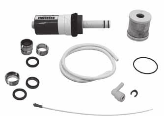
22 22 Illustration des pièces
23 Ersatzteileliste Nano RO Station List of spare parts Nano RO Station Pièces détachées Nano RO Station Gehäuse Housing Corps TFC-Membrane e Membrane d osmose TFC Carbon Block Filter Carbon Block Filter Filtre Carbon Block Metrischer Adapter Metric adapter Adaptateur métrique RO Druckschlauch /m Reverse osmosis pressure hose /1m Tuyau pour osmoseur /1m Carbon Block O-Ring Carbon Block O-Ring Joint torique Carbon Block Kapillar für 8515 Capillary for 8515 Capillaire pour Klemme für RO Anschluss Clamp for RO connection Pince pour raccord RO Winkel für RO Schlauch Angle for RO tube Coude pour tuyau RO Die Teileabbildung zeigt die mitgelieferten Einzelteile. Die Ersatzteilliste enthält auch Teile die von den Teileabbildungen abweichen können. The illustration shows the individual parts supplied. The list of spare parts may also contain parts which deviate from the illustrations. L illustration des pièces indique les différentes pièces utilisées. La liste de pièces détachées comporte aussi des pièces pouvant différer de cette illustration. 23
24 24
25 RO Station 8550 Reverse-Osmosis Station Gebrauchsanleitung Instructions for Use Mode d emploi 25
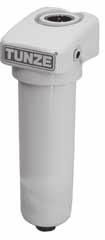
26 26 Allgemeines Die TUNZE RO Station 8550 (1) ist ein Qualität- Umkehrosmosegerät zur Reinwasserproduktion (RO-Wasser). In der Aquaristik ist sie besonders für Meer- und Süsswasseraquarien geeignet. RO Station 8550 besteht aus einem 20µm TFC-Membrane (Polysulfon- Verbindung). Die durchschnittliche Rückhalterate beträgt 98%, der Anteil des Reinwassers liegt bei ca % des verarbeiteten Wassers. Damit das Gerät seine volle Leistung erbringen kann, bitte folgende Punkte beachten!
27 General aspects TUNZE RO Station 8550 (1) is a high-quality reverse osmosis unit used to produce pure water. In aquarism it is especially suitable for marine and fresh-water aquariums. RO Station 8550 consists (polysulfone compound). The average retention rate is 98 per cent, whereby the share of pure water amounts to per cent of the processed water. In order to ensure that the unit can operate to its full capacity, the following points have to be observed. Généralités TUNZE RO Station 8550 (1) est un osmoseur inverse de qualité pour la production d eau pure, particulièrement indiqué en aquariophilie pour les aquariums d eau douce et d eau de mer. Il se 1µm et d une membrane TFC (polysulfon). La capacité de retenue se situe vers 98%, la part d eau d obtenir les performances maximales, veuillez observer ces différents points! 27
 ph-bereich: 3 10 Speisewasser: Trinkwasser (max. 0,3 mg Cl/l). Maximale Trübung: 1.0 n.t.u. Max. Anteil an gelösten Feststoffen: 2 000 ppm.")
28 28 Das Wasser sollte der Trinkwasserverordnung Ihres Landes entsprechen. Max. Wassertemperatur: 38 C, nicht am Warmwasserhahn anschließen! Gerät vor Frost schützen. Betriebsdruck: 3 bis 6 bar (40 bis 85 PSI) ph-bereich: 3 10 Speisewasser: Trinkwasser (max. 0,3 mg Cl/l). Maximale Trübung: 1.0 n.t.u. Max. Anteil an gelösten Feststoffen: ppm. Maximale Härte GH: 30 dh. Maximaler Eisenanteil : weniger als 0,1 ppm. Gesamthärte von mehr als 30 dh kann zu einer Verkürzung der Lebensdauer der Membrane führen.
29 The water should be in keeping with the regulations on potable water in force in your country. Maximum water temperature: 38 deg. Celsius (100 deg. F); do not connect to warm-water tap! Protect the unit against frost. Operating pressure: 3 to 6 bar (40 to 85 psi) ph range: 3 10 Feed water: Potable water (maximum.3 mg Cl/l) Maximum turbidity: 1.0 n.t.u. Maximum share of dissolved solids: 2,000 ppm Maximum total hardness: 30 dh Maximum content of iron: Less than.1 ppm Total hardness of more than 30 dh may lead to a reduction of the life of the membrane. L eau de conduite doit répondre aux normes de potabilité de votre région. Température maximale 38 C, pas de branchement sur un robinet d eau chaude! Veuillez protéger l appareil du gel. Pression de fonctionnement : 3 à 6 bars (40 à 85 PSI). Domaine de ph : 3 10 Eau utilisable : eau potable (max. 0,3 mg Cl/l). Turbidité maximale : 1.0 n.t.u. Part maximale en substances dissoutes : ppm. Dureté totale maximale : 30 dh. Taux de fer maximal : moins de 0,1 ppm. Une dureté totale de plus de 30 dh peut conduire à la réduction de la durée de vie de la membrane. 29
30 30 Sicherheitshinweise Montage und Wartung Installationsfachmann durchführen lassen. Umkehrosmosegerät nur mit Bodenablauf (1) in Betrieb nehmen. Bei Undichtigkeit an Schlauchverbindungen oder beim Verkalken des Ventils kann es zu Wasserschäden kommen. Bei Schlauchbruch muss sichergestellt sein, dass das wird. Anderenfalls kann es zu Wasserschäden im Wohnraum führen. Wenn kein Bodenablauf vorhanden ist, geeigneten Behälter mit Ablauf oder Ablaufmöglichkeit bzw. Auffangwanne mit Pumpe und Schwimmerschalter aufstellen. Die benötigten Leitungen vom Fachmann installieren lassen. Vorratsbehälter ebenfalls mit Ablaufmöglichkeit absichern. Leitungen vom Fachmann installieren lassen. Wichtiger Hinweis: Bei unbeaufsichtigtem Betrieb unbedingt Wasserhahn für das Umkehrosmosegerät schließen!
31 Safety instructions Commission an installation expert for the installation and servicing work. only. In case of leaks at the hose connections or if the valves are furred, water damage may occur. In case of a hose rupture, it has to be ensured that the Otherwise, water damage may occur in the room. container with drain or drain option and/or a collection tub with pump and oat switch. Have the required pipes tted by an expert. Secure the storage container with drain possibilities as well. Have the hoses installed by an expert. Important note: The reverse osmosis unit should not be operated while unattended. Sécurité d utilisation Le montage et l entretien sont à effectuer par un installateur professionnel. N utilisez l osmoseur inverse qu avec un écoulement au sol (1). Dans le cas contraire, l appareil pourrait conduire à des dégâts d eau lors de fuites au niveau Lors d une rupture de tuyauterie, l eau doit être guidée vers l évacuation au sol. Dans le cas contraire, cela pourrait conduire à des dégâts d eau dans l espace environnant. Si un écoulement au sol n est pas disponible, veuillez placer l osmoseur inverse au-dessus d un bac de récupération équipé d une pompe de type vide-cave (installation à réaliser par un professionnel). La cuve de stockage d eau osmosée doit être équipée d un trop-plein raccordé via un tuyau à l écoulement au sol (installation à réaliser par un professionnel). Remarque importante : En cas de non-surveillance de l osmoseur inverse, veuillez refermez le robinet d alimentation! 31
32 32 Leistung / Wasserproduktion: Liter /Tag bei PSI (3-6 bar) und C. Niedriger Druck und niedrige Wassertemperatur verringern die Reinwasserproduktion, z.b. bei 15 C und 3 bar Druck sind nur ca Liter/ Tag Reinwasser zu erwarten. TFC-Membrane (2) : Entfernt u. a. gelöste Salze. kleineren Sedimentanteile bis 0,5µm, Chlor, Chlorverbindungen, organische Kontaminationen, Pestizidrückstände und andere chemische Verbindungen, Geschmacks- und Geruchsbeeinträchtigungen. Rückhalteverhältnis: 20% (d.h. 20% des Wassers erhält man als Osmosewasser).
33 Performance / water production: 100 to 200 litres/day (26 to 52.8 USgal.) at 3 to 6 bar (43 to 87 PSI) and 15 deg. to 25 deg. Celsius (59 deg. to 77 deg. F). Thin- lm composite membrane (2): Removes dissolved salts, among other things. sediment particles, chlorine, compounds of chlorine, organic contaminations, residue of pesticides and of other chemical compounds, smell and taste-bearing substances. Retention ratio: 20 per cent (i.e. 20 per cent of the water is retained as osmosis water). Performances / production d eau pure: L / jour sous 3-6 bars (40-80 PSI) et C. Une pression de fonctionnement ainsi qu une température basse réduisent sensiblement la production d eau pure, par exemple 15 C et 3 bars ne donneront qu une production de 80 à 100 L d eau pure par jour. Membrane TFC (2) : retient entre autres les sels dissous. Filtres charbon / sédiments (3) : retiennent les petites particules et les sédiments jusqu à 0,5µm, le chlore, les liaisons chlorées, les contaminations organiques, les pesticides et autres substances chimiques, les substances aromatiques. l eau utilisée est transformée en eau pure). 33
 verwendet werden, die zum Betrieb einer Waschmaschine geeignet ist. Falls vorhanden, Schutzkappen an Schlauchenden entfernen.")
34 34 Montage - Inbetriebnahme RO Station Der Installationsfachmann sollte einen Wasserhahn, der den jeweiligen nationalen Maßnahmen zum Schutz des Trinkwassers entspricht verwenden. Es sollte daher eine Sicherheitsarmatur (1) verwendet werden, die zum Betrieb einer Waschmaschine geeignet ist. Falls vorhanden, Schutzkappen an Schlauchenden entfernen. Schlauchkupplung (2) an Kaltwasserleitung mit Rück ussverhinderer 3/4 anschließen. Schwarzen Schlauch (3) zum Ab uss verlegen. Das ausgeschiedene Wasser ist ge ltert, entchlort und hat eine ca. 15 % höhere Härte. Blauen Schlauch (4) in den Reinwasserbehälter verlegen. Vor Wasseranschluss prüfen, ob Kaltwasser einströmt. Kaltwasserzufuhr langsam aufdrehen und prüfen, ob alle Anschlüsse an dem Gerät wasserdicht sind. Auf dem Manometer (5) überprüfen, ob der Betriebsdruck im Bereich OPERATING steht, von 2,8 bis 6 bar (40 bis 85 PSI). Empfehlung: Die ersten 10 L produziertes Reinwasser weggießen, erst danach Wasser verwenden.
35 Installation / start-up of RO Station The installation expert should use a water tap, which corresponds to the respective national measures for the protection of potable water.for this reason an should be used, which is suitable for the operation of a washing machine. protective caps at the ends of the hoses. Connect the hose coupling (2) to the cold water hose with ¾ non-return valve. Lay the black hose (3) to the run-off. The exuded water has been ltered, dechlorinated, and has a hardness increased by about 15 per cent. Lay the blue hose (4) into the pure water tank. Prior to connection, check whether cold water is owing in. Slowly open the cold water supply, and check whether all connections of the unit are water tight. Use the pressure gauge (2) to check whether the operating pressure is within the OPERATING range of between 2.8 to 6 bar (40 to 85 PSI). produced. Subsequently the water can be used. Montage - Mise en service RO Station L installateur doit utiliser un robinet d adduction correspondant aux normes nationales de potabilité. Il doit aussi utiliser une armature de sécurité antiretour (1) indiquée pour l utilisation des lave-linge. Si utilisés, retirez les embouts de protection des tuyaux d osmoseur. Branchez le raccord (2) sur le robinet d eau froide équipé d un anti-retour 3/4. Raccordez le tuyau noir (3) vers l évacuation d eau. dureté augmentée de 15%. Raccordez le tuyau bleu (4) vers le réservoir d eau pure. en eau froide. tous les raccords de l appareil sont étanches. Sur le trouve bien dans la zone «OPERATING» de 2,8 à 6 bars (40 à 85 PSI). Conseil : veuillez ne pas utiliser les dix premiers litres de production d eau pure. 35

 darf nie austrocknen.")
36 36 Wartung Das Umkehrosmosegerät TUNZE RO Station 8550 braucht keine besondere Wartung. Wir empfehlen jedoch folgende Punkte zu beachten: Um eine bestmögliche Entfernung von Schadstoffen zu gewährleisten und gleichzeitig die Membrane vor vorzeitiger Zerstörung zu schützen, sollten Abständen von sechs Monaten ausgewechselt werden. Wenn das Wasser einen hohen Anteil an elt werden, um eine entsprechende Leistung zu bringen (Reinwassermenge nimmt ab). Die TFC-Membrane (4) darf nie austrocknen. Um einen Schlauch vom Osmosegerät zu lösen, zuerst die Klemme für RO Anschluß abziehen (5), Verriegelungsring nach innen drücken (6) und gleichzeitig Schlauch herausziehen (7). Für die genaue Bestimmung der Wasserqualität empfehlen wir TUNZE RO TDS Monitor 8533 (8) oder Conductivity-Meter 7032/2 (9).
37 Servicing The TUNZE RO Station 8550 reverse osmosis plant does not require any special servicing. However, we recommend observing the following points: In order to ensure the best possible removal of impurities and to protect the membrane against premature destruction at the same time, the (3) should be replaced in regular intervals of six months. If the water has a high degree of residue, the be replaced more frequently, if a corresponding performance is to be ensured (pure water quantity decreases). The thin- lm composite membrane (4) must never dry out. In order to remove the hose from the osmosis plant, press the lock ring to the inside (6), and pull the hose out at the same time (7). For the precise determination of the water quality, we recommend the use of TUNZE RO TDS Monitor 8533 (8) or Conductivity Meter 7032/2 (9). Entretien L osmoseur inverse TUNZE RO Station 8550 ne nécessite pas d entretien particulier. Nous conseillons cependant d observer les points suivants : bonne qualité de l eau pure et de prolonger la durée de vie de la membrane. Si l eau possède une forte concentration en particules plus courtes. La membrane TFC (4) ne doit jamais sécher. pince du raccord RO (5).poussez la bague de verrouillage (6) et tirez simultanément le tuyau (7). Pour un contrôle précis de la conductivité de l eau pure, nous conseillons l utilisation de TUNZE RO TDS Monitor 8533 (8) ou du conductimètre TUNZE 7032/2 (9). 37
38 38 Filtergehäuse aufschrauben (1). Filtersieb entfernen ( Wasser ausspülen. Filter wieder einsetzen und Gehäuse zuschrauben. Schlauchanschlüsse überprüfen. Wec Filtergehäuse mit Schlüssel (3) abschrauben. Alte Filter entfernen (4). Neue Filter einsetzen. Die Schlauchanschlüsse überprüfen, darauf achten, dass die Muttern nicht mit Gewalt überdreht werden. System einschalten und prüfen, ob undichte Stellen vorhanden sind.
39 water. Place t the housing again. Check the hose connections. Rem er (4). Place the new lter. Check the hose connections, and make sure that the nuts are not forcibly overtightened. Switch on the system and check whether there are any leaking points. courante (2). générale de l appareil. 39
40 40 Membrane erneuern TUNZE RO Station 8550 enthält eine Dünnschichtverbundmembrane mit einer Lebensdauer von ca. drei bis fünf Jahren. Wann die Umkehrosmosemembrane gewechselt werden muss, kann durch Vergleichen der Leitfähigkeit des Speisewassers mit der des Reinwassers sowie geprüft werden. Membrane wie folgt austauschen: Schwarzen Schlauch vom Zulauf des Umkehrosmose-Membrangehäuses entfernen (1) und Gehäuse von den Klammern nehmen. Gehäusedeckel gegen Uhrzeigersinn abschrauben (2). Achtung, kann sehr fest sitzen! Danach mit einer Zange den Fuß der Membrane greifen und die Membrane aus dem Gehäuse ziehen (3). Die neue Membrane mit dem O-Ring- Teil zuerst einsetzen (4). Nach Ausrichtung der Membrane, diese bis zum Boden in den Zylinder drücken (5). Den O-Ring am Gehäuserand des Moduls falls notwendig auswechseln (6) und dann den Deckel vorsichtig wieder festschrauben. Das Membrangehäuse mit den Klammern befestigen und den schwarzen Schlauch mit dem Zulauf des Umkehrosmosemoduls verbinden.
41 Replacing the membrane composite membrane with a service life of between membrane has to be changed, can be determined by comparing the conductivity of the feed water and of the pure water as well as by determining the water volume running off. The membrane is replaced as follows: Remove the black hose from the inlet of the reverse osmosis membrane housing (1), and take the hose from the brackets. Unscrew the housing cover counter-clockwise (2). Caution: May be very tight! Subsequently, use pliers to get hold of the foot of the membrane, and then pull the membrane out of the housing (3). Place After aligning the membrane, press up to the bottom of the cylinder (5). If and when required, replace the O-ring seal at the housing edge of the module (6), and then screw on the cover again carefully. Use the brackets to fasten the membrane housing, and then connect the black hose to the supply of the reverse osmosis module. Remplacement de la membrane TUNZE RO Station 8550 possède une membrane TFC ayant une durée de vie d environ trois à cinq années. Le remplacement de la membrane sera déterminé par une comparaison de la conductivité de l eau en entrée et en sortie d osmoseur (eau pure) tout comme par la diminution de la quantité d eau pure produite. Remplacez la membrane comme suit : Retirez le tuyau noir d arrivée d eau (1) et retirez le corps de ses supports. Dévissez le couvercle du corps dans le sens antihoraire (2). Attention, cela peut nécessiter une certaine force! Saisissez le pied de la membrane à l aide d une pince et retirez la membrane du corps plastique (3). La nouvelle membrane doit être insérée par le côté comportant le joint torique (4). Après positionnement, poussez la membrane dans le corps jusqu à son extrémité (5). Si nécessaire, remplacez le joint torique (6) sur le verrouillage du corps puis refermez le couvercle du corps avec précaution. Insérez le corps de membrane dans les pinces de d eau. 41
42 42 Zubehör RO Water Controller 8555 (1) Für eine automatische Wasserstandskontrolle von TUNZE RO Station 8550 für einen Reinwasserbehälter. Beachten Sie auch die Sicherheitshinweise beider Geräte! Montage des Ventils Schwarzen Schlauch (2), der vom Filter zur Membrane führt, entfernen (1/4 Schlauchkupplung). Eingang des Ventils Richtung Filter verbinden (3). Ausgang des Ventils Richtung Membrane verbinden (4). Schlauch bei Bedarf mit scharfem Messer kürzen. RO Ion Exchanger (5) Station, verwendbar als Wasseraufhärter oder Silikatentferner.
43 Accessories RO Water Controller 8555 (1) For automatic water level control of TUNZE RO Station 8550 in a pure water container. Please also observe the safety instructions of both devices! Installation of the valve Remove the black hose (2) which leads from the Connect er (3). Connect the valve in direction of the membrane (4). Use a sharp knife to shorten the hose, if and when required. RO Ion Exchanger (5) Station which can be used to add hardness or to remove silicate. Accessoires RO Water Controller 8555 (1) Remise à niveau automatique avec régulation pour osmoseur inverse TUNZE RO Station 8550 et réservoir d eau pure. Veuillez observer les sécurités d utilisation des deux appareils! Montage de l électrovanne membrane (raccord 1/4 ). Raccordez la sortie de l électrovanne à la membrane (4). Si nécessaire, adaptez la longueur du tuyau à l aide d un couteau bien tranchant. RO Ion Exchanger (5) Filtre complémentaire en sortie d osmoseur, silicates. 43

44 44 Illustration des pièces <2012 > a
45 Ersatzteilliste RO Station List of spare parts RO station Pièces détachées RO Station Ersatzmembrane für 8550 Spare membrane for 8550 with US-version capillary Membrane de rechange pour Filtre sédiments 5µm Filtre charbon / sédiments 1µm Filtre sédiments 20µm O-Ring für Membrangehäuse O-ring seal for membrane housing Joint torique pour corps de membrane O-Ring für Filtergehäuse Kapillare für 8550 Capillary for 8550 Capillaire pour Manometer 1/8, 0-10bar Pressure gauge 1/8 Manomètre 1/8,0-10b RO Druckschlauch /m Reverse osmosis pressure hose /1m Tuyau pour osmoseur /1m Verschraubung 3/4 3/4 in. screw connection Raccord 3/4 10a _A Verschraubung 3/4 (USA) 3/4 in. screw connection (USA) Raccord 3/4 USA Verschraubung 1/4 beidseitig 1/4 nylon nipple Raccord double 1/ Winkel 1/4 für RO Schlauch 1/4 in. elbow for reverse osmosis hose Angle 1/4 pour tuyau osmoseur Winkel 1/8 für RO Schlauch 1/8 in. elbow for reverse osmosis hose Angle 1/8 pour tuyau osmoseur 14a /4 Anschluß mit RO nippel 1/4 connector with RO pipe Raccord RO 1/4 14b Winkel für RO Schlauch Angle for RO tube Coude pour tuyau RO 14c T-Stück für RO Station 8550 T-piece for RO Station 8550 Pièce en T pour les RO Station Klemme für RO Anschluss Clamp for RO connection Pince pour raccord RO Schlüssel für 8550 Wrench for 8550 Clé pour 8550 Die Teileabbildung zeigt die mitgelieferten Einzelteile. Die Ersatzteilliste enthält auch Teile die von den Teileabbildungen abweichen können. The illustration shows the individual parts supplied. The list of spare parts may also contain parts which deviate from the illustrations. L illustration des pièces indique les différentes pièces utilisées. La liste de pièces détachées comporte aussi des pièces pouvant différer de cette illustration. 45
46 46
47 RO Ion Exchanger Gebrauchsanleitung Instructions for Use Mode d emploi 47
48 48 Allgemeines angebracht werden. Der Behälter enthält eine Schraubkappe (1), Steckverbindungen für den Osmosegeräteschlauch und zwei Klemmen Art. Nr (2) für eine direkte Befestigung auf der RO Station. Wir empfehlen besonders den Einsatz der Kieselsäure. Dadurch können Kieselalgen und Schmieralgen in Aquarien verhindert werden. Als Medium wird ein Mischbett-Ionenaustauscher mit Farbumschlag verwendet, Art. Nr Um den Calciumgehalt des RO-Ausgangswassers zu erhöhen, kann anstelle des Mischbett- Ionenaustauscher-Granulates das Kalkgranulat Calcium Carbonate Art. Nr eingefüllt werden. Das RO- Ausgangswasser nimmt hohe Mengen an Calcium-Hydrogencarbonat auf. Das RO-Ausgangswasser wird dabei aufgehärtet, die Karbonathärte wird erhöht. Dieses Gerät ist für Benutzer (einschl. Kinder) mit eingeschränkten physischen, sensorischen oder psychischen Fähigkeiten bzw. ohne jegliche Erfahrung oder Vorwissen nur dann geeignet, wenn eine angemessene Aufsicht oder ausführliche Anleitung zur Benutzung des Geräts durch eine verantwortliche Person sichergestellt ist (3).
49 General aspects of the RO Station as a water hardener or silicate type connectors for the hose of the osmosis plant and two brackets, article No , (2) for a direct attachment on the RO Station. In particular, outlet in order to remove the silicic acid. Thus, the growth of diatoms and mucous algae can be avoided in the aquarium. A mixed-bed ion exchanger with colour change is used as a medium (article No ). In order to increase the calcium content of the out-going RO water, the mixed-bed ion exchanger granulate can be replaced by the calcium carbonate granulate (article No ). The out-going RO water takes up high quantities of calcium hydrogen carbonate. In the process, the hardness of the outgoing RO water is increased, i.e. the carbonate hardness is increased. This device is suitable for users (including children) with limited physical, sensorial or mental abilities or without any experience or previous knowledge, if suitable supervision or detailed instructions on the operation of the device is provided by a responsible person (3). Généralités à silicates. Le corps comprend un bouchon à visser (1), deux raccords pour les tuyaux d osmoseur et deux pinces de maintien référence (2) pour une en sortie d osmoseur pour une élimination de l acide siliciques, ce qui permet de diminuer la présence d algues cyanophycées dans l aquarium. Le substrat mélangés avec changement de coloration, référence d osmoseur, le substrat à lits mélangés peut être remplacé par Calcium Carbonat référence L eau osmosée possède une forte capacité de reminéralisation par le carbonate de calcium ce qui permet d augmenter sensiblement la dureté carbonatée. Les utilisateurs (enfants inclus) ayant des limitations peuvent utiliser cet appareil qu avec le concours d une tierce personne responsable, assurant la surveillance ou veillant à l observation du mode d emploi. Veuillez vous assurer que les enfants ne puissent jouer avec cet appareil (3). 49
50 50 Inbetriebnahme RO Ion Exchanger mit den Klemmen auf der RO Station befestigen (1) und mit dem blauen Schlauch (Reinwasser) (2) verbinden. Das Filtermaterial muss regelmäßig und je nach Wassermenge gewechselt werden! Dies ist der Fall, wenn sich der Farbumschlag verfärbt hat. Die Anfangsfärbung kann unterschiedlich sein, grünlich wird bläulich, gelblich wird braun-rot und blaupurpurot wird orange. Der RO Exchanger soll an einem lichtgeschützten Bereich angebracht werden. Tageslicht kann den Farbumschlag schneller verfärben! Als Medium wird ein Mischbett-Ionenaustauscher mit Farbumschlag verwendet, Art. Nr Es soll kühl und lichtgeschützt und vor Austrocknung sicher gelagert werden, es ist nur begrenzt haltbar! Wenn Sie den Ion Exchanger zum Aufhärten verwenden wollen: Kappe aufschrauben (3). Geeignetes Filtermaterial einsetzen, wir empfehlen besonders Calcium Carbonate Art. Nr (4). Kappe zuschrauben.
51 Initial operation Use the brackets to attach the RO Ion Exchanger on the RO Station (1), and connect with the blue hose (pure water) (2). has to be exchanged in regular intervals! This is the case when the indicator has changed colours. The initial colour may differ greenish will change to bluish, yellowish to reddish-brown and bluish purple red to orange. protected area. Daylight may accelerate the colour change! A mixed-bed ion exchanger with colour change indicator is used as a medium (article No ). It should be stored in a cool and light-protected place, safe against drying; it keeps for a limited period of time only! If you want to use the Ion Exchanger for water hardening: Unscrew the cap (3). calcium carbonate in particular (article No ) (4). Screw the cap back on again. Mise en service l osmoseur RO Station (1) et raccordez-le au tuyau bleu d eau pure (2). uemment remplacé et ceci en fonction de la quantité d eau qui a été utilisée. Ce moment est matérialisé par un changement de coloration du matériau sachant que la coloration de départ peut être très diverse: vert devient bleu, jaune devient brun/rouge, bleu/rouge devient orange. RO Ion Exchanger doit être placé à un endroit abrité de la lumière directe. La lumière du jour peut accélérer le changement de coloration! d ions à lits mélangés avec changement de coloration, référence Il doit être stocké au frais, à l abri de la lumière et ne doit jamais sècher. Sa durée de conservation est limitée! Si vous désirez utiliser Ion Exchanger comme reminéralisateur : Dévissez le bouchon (3). Remplissez le corps avec un matériau adapté (nous conseillons tout spécialement Calcium Carbonat (4). Revissez le bouchon. 51
52 52

53 RO Water Controller 8555 Gebrauchsanleitung Instructions for Use Mode d emploi 53
, zwei Sensoren (2), einem Wasserventil (3) und einem 11V- Netzteil (4). Je nach Bedarf kann das Wasserventil durch die Schaltsteckdose 3150.")
54 54 Allgemeines Der TUNZE RO Water Controller 8555 ist eine automatische Wasserstandsregelung für die TUNZE RO Station mit Reinwasserbehälter oder jeden anderen Wasserbehälter mit Nachfüllautomatik für Aquarien. Er besteht aus einem Controller (1), zwei Sensoren (2), einem Wasserventil (3) und einem 11V- Netzteil (4). Je nach Bedarf kann das Wasserventil durch die Schaltsteckdose (5) für Netzbetrieb ausgetauscht werden. Für die Nano RO Station 8515 wird dieses Nachfüllgerät nicht empfohlen. Wird die Position der Sensoren des RO Water Controllers vertauscht, kann mit der Schaltsteckdose und einer Pumpe ein Wasserbehälter zielgesteuert entleert werden, er kann damit zum automatischen Füllen oder Leeren von Behältern verwendet werden. Mit zwei Gerätekombinationen lässt sich eine Wasserwechselanlage bauen. Dieses Gerät ist für Benutzer (einschl. Kinder) mit eingeschränkten physischen, sensorischen oder psychischen Fähigkeiten bzw. ohne jegliche Erfahrung oder Vorwissen nur dann geeignet, wenn eine angemessene Aufsicht oder ausführliche Anleitung zur Benutzung des Geräts durch eine verantwortliche Person sichergestellt ist (6).
55 General aspects TUNZE RO Water Controller 8555 is an automatic water level regulator for the TUNZE RO Station with pure water tank or with any other water tank with of a controller (1), two sensors (2), a water valve (3), and an 11 V power supply unit (4). Depending on the operation by means of the switched socket outlet (5) for mains operation. We do not recommend Station If the position of the sensors of the RO Water Controller is reversed, the switched socket outlet and a pump can be used to empty a water tank, and thus it can also be used for automatic By means of two combinations, a water changing system can be built. This device is suitable for users (including children) with limited physical, sensorial or mental abilities or without any experience or previous knowledge, if suitable supervision or detailed instructions on the operation of the device is provided by a responsible person (6). Généralités TUNZE RO Water Controller 8555 est une remise à niveau automatique avec régulation pour osmoseur inverse TUNZE RO Station ou tous types d osmoseurs inverses avec réservoir d eau pure. Il se compose d un contrôleur (1), de deux capteurs (2), d une électrovanne (3) et d une alimentation secteur 11V (4). Pour piloter un appareil alimenté sur secteur, l électrovanne peut être remplacée par la prise commandée (5). Cet appareil n est pas conseillé pour Nano RO Station Il est encore possible d effectuer la vidange contrôlée d un réservoir en inversant simplement la position des capteurs RO Water Controller tout en utilisant une prise commandée. En combinant deux appareils, il est possible de construire une installation de changement d eau automatique. Les utilisateurs (enfants inclus) ayant des limitations pas d une expérience ou de connaissances le concours d une tierce personne responsable, assurant la surveillance ou veillant à l observation du mode d emploi (6). 55
, d.h. ein Sensor (1) zum Einschalten des Ventils und zum Überwachen des Wasserniveaus (LED Water on) und ein Sensor 2) zum Ausschalten (LED Water off).")
56 56 Entsorgung: (nach RL2002/96/EG) Gerät und Batterie dürfen nicht dem normalen Hausmüll beigefügt werden, sondern müssen fachgerecht entsorgt werden. Wichtig für Europa: Gerät über Ihre kommunale Entsorgungsstelle entsorgen. Funktion TUNZE RO Water Controller 8555 verwendet zwei Sensoren (Schwimmschalter), d.h. ein Sensor (1) zum Einschalten des Ventils und zum Überwachen des Wasserniveaus (LED Water on) und ein Sensor 2) zum Ausschalten (LED Water off). Der Controller enthält auch eine elektronische Zeitüberwachung die nach 12 Stunden (Auslieferungszustand) oder 24 Stunden. Dauerlauf das Ventil stoppt (Time out). Dies kann einen Überlauf des Behälters vermeiden, z.b. bei Blockierung eines Sensors. Nach Drücken der Taste Reset (3) ist dann der Water Controller wieder arbeitsfähig. Montage des Ventils, siehe Anleitung 8550 / Zubehör.
57 Disposal (in keeping with RL2002/96/EU) The device and the battery may not be disposed of in normal domestic waste; it has to be disposed of in an expert manner. Important for Europe: Devices can be disposed of through your community s disposal area. Function TUNZE RO Water Controller 8555 uses two on the valve and to monitor the water level (LED Water On) and one sensor (2) for switching the system off (LED Water Off). The controller also contains an electronic time monitor, which stops the valve after twelve hours (delivery condition) or twenty-four hours of continuous operation (time over when a sensor is blocked, for example. After pressing the Reset (3) button, the water controller is operational again. Installation of the valve, see instructions 8550 / accessories. Gestion des déchets (directive RL2002/96/EG) Cet appareil et sa batterie ne doivent pas être jetés dans les poubelles domestiques mais dans les conteneurs spécialement prévus pour ce type de produits. Important pour l Europe : l appareil doit être recyclé par votre centre de recyclage communal. Fonction TUNZE RO Water Controller 8555 utilise deux à-dire un capteur (1) pour l enclenchement de l électrovanne et la surveillance du niveau d eau (LED Water on) et un capteur (2) pour le déclenchement (LED Water off). Le contrôleur comporte aussi une surveillance de la durée d enclenchement, arrêtant l électrovanne après un temps de fonctionnement continu de 12 heures (réglage de série) ou 24 heures (Time out). Cette sécurité peut éviter un débordement du réservoir d eau pure, par exemple suite au blocage d un capteur. Après une action sur le bouton «Reset» (3), Water Controller est à nouveau opérationnel. Pour le montage de l électrovanne, voir notice 8550 / Accessoires. 57
58 58 Sicherheitshinweise Netzteil und Controller 8555 nur an trockener und gut belüfteter Stelle anbringen! (1) Nicht in die Nähe von Heiz- und Wärmequellen aufstellen (2), Umgebungstemperatur max C. Kabel nicht knicken (3). Magnetscheibenreiniger oder andere Magnete nicht in die Nähe des Sensors bringen, sonst Funktionsstörung möglich, mind. 20 cm Abstand halten (4). Vor Inbetriebnahme prüfen, ob Betriebsspannung mit Netzspannung übereinstimmt. Kabel nicht reparieren, sondern Geräte zur Reparatur geben. Nur an empfohlene TUNZE-Geräte anschließen. Beim Betrieb kann das Ventil heiß werden (ca 60 C). Schwimmschalter, interne elektrische Komponenten und Ventil kann fest werden und an angeschlossenen Umkehrosmosegeräten Wasserschäden verursachen. RO Water Controller daher nicht unbeaufsichtigt betreiben. Bitte beachten Sie auch die Sicherheitshinweise bei den RO-Geräten! Gebrauchsanleitung gut aufbewahren.
59 Safety instructions Mount power supply unit and controller 8555 in dry and well ventilated locations only! (1) Do not mount in the vicinity of heat sources (2); ambient temperature max. 35 Celsius (95 F). Do not kink the cable (3). Do not situate magnetic pane cleaners or other magnets in the vicinity of the sensor, as otherwise functional failure is possible; keep a distance of at least 20 cm (7.8 in.). Prior to initial operation, please check whether the operating voltage corresponds to the mains voltage available. Do not repair a damaged mains cable, but have the units repaired. Connect to recommended TUNZE units only. During the operation, the valve may turn hot (approx. 60 Celsius / 140 F). Float switches, internal electric components and valves can cease up, and may cause water damage to the reverse osmosis units connected. For this reason, do not operate the RO Water Controller unattended. Please also observe the safety instructions for the RO units! Keep the operating instructions in a safe place. Sécurité d utilisation Positionnez l alimentation et le Controller 8555 en un endroit sec et bien aéré! (1) Ne positionnez pas les appareillages près d une source de chaleur (2), température max. +35 C. Ne pliez pas les câbles (3). sources magnétiques à moins de 20 cm des capteurs (4). de l alimentation avec le réseau électrique. N essayez pas de réparer un câble mais renvoyez l appareil au Service Réparations. Ne raccordez RO Controller qu aux appareillages TUNZE conseillés. Lors de son fonctionnement, l électrovanne peut être très chaude (env. 60 C). Les capteurs, les composants électriques internes et l électrovanne peuvent se bloquer et provoquer un débordement par fonctionnement permanent de l osmoseur inverse. Pour cela, ne pas utiliser RO Water Controller sans surveillance. Veuillez observer les sécurités d utilisation des appareils RO! Veuillez attentivement consulter le mode d emploi. 59
.")
60 60 Platzwahl für Controller 8555 Wand muss trocken sein, Platz nicht über dem Aquarium wählen! (1) Vorhandene Kabellänge beachten, Verlängerung nicht möglich! Kontrollleuchten müssen sichtbar sein! Kabelanschlüsse so verlegen, dass kein Wasser entlang laufen kann und in den Controller gelangt! (2). Befestigung Zur Befestigung des Controllers sind die beiliegenden selbstklebenden Kunststoff- Hakenbänder vorgesehen (3). Untergrund muss fettfrei, sauber und glatt sein, z.b. Kunststoff äche. Bänder auf Gehäuse kleben, dazu Schutzfolie abziehen und anpressen. Danach die zweite Schutzfolie abziehen und Gerät an gewünschter Stelle positionieren und andrücken, dabei auf die Lage der Kabel achten.
61 Selecting the position for Controller 8555 The wall has to be dry; do not select a position above the aquarium! (1) Observe available cable length; an extension is not possible! The indicator lamps have to be visible! Place the cable connections in such a way that no water can run along and get into the controller (2)! Attachment For attachment of the controller, please use the plastic self-adhesive hook and loop strips enclosed (3). The surface has to be free from grease, clean and smooth, such as a plastic surface. Stick the strips to the housing; for this purpose remove the protective lm and press down. place the unit at the requested position and press down, observing the position of the cable in the process. Placement du Controller 8555 La surface doit être sèche, n utilisez pas un emplacement au-dessus de l aquarium! (1) Observez la longueur des câbles, leur prolongation est impossible! Les voyants lumineux doivent rester visibles! Positionnez les câbles de telle manière à ce que la pénétration de l eau dans le boîtier soit impossible! (2). Fixation bandes Velcro autocollantes (3). La surface de collage doit être propre, sèche et plane, par exemple une surface en matière plastique. Collez les bandes Velcro sur le boîtier, pour cela retirez les protections puis pressez. Déposez les deux protections restantes, positionnez l appareil à l endroit voulu en observant la longueur 61
 Schiebeteil mit Halteplatte für Sensor an gewünschte Stelle positionieren. Bei der Halteplatte (5) muss der Stift in Richtung Schwimmer zeigen.")
62 62 Halterung der Sensoren an senkrechter Aquarienscheibe oder Behälter (1) Halter vormontieren. (2) Einstellen der Glasstärke (max.19mm) mit der unteren Halteschraube. (3) Klemmschraube anziehen. Auf festen Sitz achten. (4) Schiebeteil mit Halteplatte für Sensor an gewünschte Stelle positionieren. Bei der Halteplatte (5) muss der Stift in Richtung Schwimmer zeigen. Sensor mit Kabel nach oben in Sensorhalter einführen, danach Sensorschrauben anziehen. Zubehör (6) Für Glasscheiben bis 39mm Dicke gibt es längere Schrauben: 2 Schrauben M5 x 60 mm, Art. Nr
63 Holding device of the sensors on a vertical aquarium pane or on a tank (1) Premount the holding device. (2) Use the lower retaining screw to set the glass thickness (max. 19 mm (.74 in.)). (3) Tighten the clamping screw. Ensur (4) Position the sliding part at the requested position by means of the holding plate of the sensor. The pin on holding plate (5) has to point in direction of the oat switch. Insert the sensor with cable upwards into the sensor holding device; subsequently tighten the sensor screws. Accessories (6) Longer screws are available for glass panes up to a thickness of 39 mm (1.33 in.): 2 screws M5 x 60 mm (2.36 in.), article No Fixation des capteurs sur vitre verticale ou conteneur (1) Procédez à un premier assemblage du support. (2) Ajustez le support à l épaisseur du verre (max. 19mm) à l aide de la vis de réglage inférieure. (3) Serrez la vis de réglage supérieure, veillez à une bonne assise. (4) Positionnez la pièce coulissante du support de capteur à la position souhaitée. Sur la plaque de Insérez le capteur dans le support, câble vers le haut, puis resserrez l écrou du capteur. Accessoire (6) Pour des épaisseurs de vitre jusqu à 39mm, utilisez les deux vis inox M5x60mm, référence

64 64 Water on Water off Sensorhalterung mit Verlängerung an senkrechter Aquarienscheibe oder Behälter befestigen (7) Verlängerung mit Halteschiene verbinden, dazu Gewindeplatte an der Rückseite der Schienen einsetzen und mit je einer Schraube von vorn befestigen. (8) Weitere Montageschritte siehe wie beschrieben bei Halterung an senkrechter Aquarienscheibe oder Behälter (1-5).
65 Attaching the sensor holding device with extension to a vertical tank pane or tank (7) Use the retaining rail to link the extension; for this purpose place the threaded plate on the rear side of the rails and screw down from the front with one screw each. (8) For other mounting steps, please refer to the description in Attachment to vertical aquarium pane or container (1-5). Fixation des capteurs avec prolongateur sur vitre verticale ou conteneur (7) Raccordez la prolongation et la barre de montage initiale. Pour cela, placez la plaquette à l arrière des barres et solidarisez le tout à l aide des deux vis insérées par l avant. (8) Autres étapes de montage, voir Fixation des capteurs sur vitre verticale ou conteneur (1-5). 65
 Halteschiene mit Schiebeteil für Sensor (5) vormontieren, dabei gewünschte Position des Sensors einstellen.")
66 66 Halterung der Sensoren an waagerechter Aquarienscheibe oder Behälter (1) Klemmhalter vormontieren. (2) Einstellen der Glasstärke (max.19mm) mit der Halteschraube. (3) Klemmschrauben anziehen. (4) Halteschiene mit Schiebeteil für Sensor (5) vormontieren, dabei gewünschte Position des Sensors einstellen. (6) Schraube und Mutter an Halteschiene lose befestigen und in Klemmhalter (1) einhängen und festschrauben. Sensor mit Kabel nach oben in Sensorhalter einführen, danach Sensorschrauben anziehen. Zubehör (7) Für Glasscheiben bis 39mm Dicke gibt es längere Schrauben: 2 Schrauben M5 x 60mm, Art. Nr
67 Holding device of the sensors on a horizontal aquarium pane or on a tank (1) Premount the holding clamp. (2) Use the retaining screw to set the glass thickness (max. 19 mm (.74)). (3) Tighten the clamping screws. (4) Premount the retaining rail with the sliding part for the sensor (5), and set the requested position of the sensor in the process. (6) Loosely t the screw and nut on the retaining rail, suspend in holding clamp (1), and screw down. Insert the sensor with cable upwards into the sensor holding device; subsequently tighten the sensor screws. Accessories (7) Longer screws are available for glass panes up to a thickness of 39 mm (1.53 in.): 2 screws M5 x 60 mm (2.36 in.), article No Fixation des capteurs sur vitre horizontale ou conteneur (1) Procédez à un premier assemblage du support. (2) Ajustez l ensemble de serrage du support à l épaisseur du verre (maxi 19 mm) par la vis de réglage. (3) Serrez la vis de serrage. (4) Assemblez la barre de montage et la pièce coulissante pour le capteur (5), choisissez la bonne position du capteur. le tout au support (1) à l aide de l écrou. Insérez le capteur dans le support, câble vers le haut, puis resserrez l écrou du capteur. Accessoires (7) Pour des épaisseurs de vitre jusqu à 39mm, utilisez les deux vis inox M5x60mm, référence

68 68 Halterung an Glasscheibe kleben Bei dieser Befestigung entfällt der übliche Klemmhalter. Dafür müssen zwei Halteplättchen pro Halteschiene mit Silikonkleber Art. Nr an die Aquarienscheibe geklebt werden. Wir empfehlen die Verklebung an der Luft, da die Haltbarkeit unter Wasser geringer ist und nur gelingt, wenn folgendes genau beachtet wird: Schiebeteile (2) und Schiene (1) des Halters zusammenschieben und Gewindeplatte (3) an den äußersten Enden der Schiene mit je einer beiliegenden Schraube (4) festschrauben, glatte liegen. Bei trockener Verklebung, Klebestelle mit Reinigungsbenzin (fettfrei) säubern. Bei Unterwasserverklebung, die Klebestelle im Aquarium mit Klingenreiniger von Algen und Gereinigte Gewindeplatten (3) gleichmäßig mit 2-3 mm Silikon (5) einstreichen und fest an Scheibe drücken, dabei soll Silikon in das leere Gewindeloch eindringen. Silikon unter Wasser innerhalb von 20 Sekunden wegen Hautbildung verarbeiten. Klebung muss 24 Stunden unbelastet aushärten.
69 Sticking the holding device on to the glass pane The standard holding clamp is not required for this type of attachment. Instead, two retaining plates for each perforated rail have to be adhered to the tank pane with silicone adhesive, article No We recommend to carry out the attachment work in fresh air as the holding capacity is lower in water and is successful only, if the following points are observed: Push the sliding parts (2) and the rail (1) of the holding device together, and screw down the threaded plate (3) at the extreme ends of the rail with one of the enclosed screws (4) each; the smooth plate surface has to make contact to the rail. For dry sticking, use cleansing alcohol (free of petroleum or oils) to clean the sticker point. For under-water attachment, use the blade cleaner to remove algae and any slimy lm from the attachment point in the tank. Apply 2 to 3 mm (.07 to.11 in.) of silicone (5) to the cleaned threaded plates (3), and press them down on to the pane tightly so that the silicone penetrates the empty threaded hole. Under water, process the silicone within 20 seconds to avoid skin formation. The bond has to cure for 24 hours without load. Fixation par collage Chaque barre de montage nécessite deux plaquettes à coller sur la vitre à l aide de colle silicone référence Nous recommandons le qu en observant scrupuleusement la procédure suivante : Assemblez la barre de montage (1) et la pièce coulissante (2), montez les deux plaques de collage (3) aux extrémités de la barre à l aide des vis (4), parties plates des plaques de collage côté barre. Pour un collage à l air, nettoyez les parties à coller à l aide d un dégraissant. Pour un collage sous eau, débarrassez les vitres raclette à lame. Recouvrez les plaques de collage dégraissées (3) d une épaisseur de 2 à 3 mm de colle silicone (5) et appliquez le tout contre la vitre. La colle doit Sous eau, le temps de a mise en place ne doit pas dépasser 20 sec. en raison de la formation d une peau de surface sur la colle. Le collage doit avoir polymérisé durant 24 heures avant toute sollicitation mécanique. 69
 Water off leuchtet = Wasserstand hoch, Ventil außer Betrieb. Rote LED (4) Time out leuchtet = elektronische Zeitüberwachung, die nach 12 Stunden (Auslieferungszustand) oder 24 St.")
70 70 Leuchtdioden (LED) am Controller 8555 Grüne LED (1) DC Power leuchtet = Controller mit Strom versorgt. Gelbe LED (2) Water on leuchtet = Wasserstand niedrig, Ventil in Betrieb. Gelbe LED (3) Water off leuchtet = Wasserstand hoch, Ventil außer Betrieb. Rote LED (4) Time out leuchtet = elektronische Zeitüberwachung, die nach 12 Stunden (Auslieferungszustand) oder 24 St. Dauerlauf das Ventil stoppt (Time out). Nach Drücken der Taste Reset wird dann der Controller wieder arbeitsfähig.
71 Light-emitting diodes (LEDs) on Controller 8555 Green LED (1) DC Power is lit = controller is energized. Yellow LED (2) Water On is lit = water level low; valve in operation. Yellow LED (3) Water Off is lit = water level high; valve not operating. Red LED (4) Time Out is lit = an electronic time monitor, which stops the valve after twelve hours (default condition) or twenty-four hours of continuous operation (time out). After pressing the Reset button, the controller is operational again. Controller 8555 et diodes LED LED verte (1) DC Power allumée = Controller sous tension. LED jaune (2) Water on allumée = niveau d eau bas, électrovanne en service. LED jaune (3) Water off allumée = niveau d eau haut, électrovanne hors service. LED rouge (4) Time out allumée = arrêt de l électrovanne par surveillance de la durée d enclenchement, temps de fonctionnement continu de 12 heures (réglage de série) ou 24 heures dépassé (Time out). Après une action sur le bouton «Reset», le Controller est à nouveau opérationnel. 71
.")
72 72 Einstellen der Zeitüberwachung (Time out) Im Controller 8555 kann die Zeitüberwachung je nach Anlage und Bedarf auf 12 (Auslieferungszustand) oder 24 St. eingestellt werden. Sie kann eine Überfüllung des Behälters vermeiden, z.b. bei Blockierung eines Sensors. Netzstecker ziehen! Deckel entnehmen, dazu beide Schrauben auf Gehäuserückseite lösen (1). Jumper (roter Stift) auf Platine verstellen (2). Achtung Leuchtdioden (LED) und Kabel nicht beschädigen! Zubehör Schaltsteckdose Bei dem Water Controller 8555 kann das beiliegende Ventil durch die Schaltsteckdose für Netzbetrieb ersetzt werden (3). Dazu wird das Kabel der Schaltsteckdose am Platz des Ventils an die Lüsterklemme des Controllers angeschlossen (Niedervolt Spannung) und die Schaltsteckdose am Netzstecker eingesteckt. Die Schaltsteckdose kann zum Schalten von Kreiselpumpen, Dosierpumpen, etc. mit 230V max.1800w (115 V / 900W) verwendet werden.
73 Setting the time monitor (time out) Depending on the plant and the requirement, the time monitor in the controller 8555 can be set to twelve hours (default condition) or twenty-four over when a sensor is blocked, for example. Remove the mains plug! Remove the cover; for this purpose undo the screws on the rear side of the housing (1). Adjust jumper (red pin) on the PCB (2). Caution! Do not damage the light-emitting diodes (LEDs) or the cables in the process! Accessories Switched socket outlet In case of TUNZE RO Water Controller 8555, the enclosed valve can be replaced by switched socket outlet for mains operation (3). For this purpose, the cable of the switched socket outlet is connected to the luster terminal of the controller instead of the valve (low voltage) and the switched socket outlet is plugged to the mains plug. The switched socket outlet can be used to switch centrifugal pumps, metering pumps, et cetera with 130 V, max. 1,800 W (115 V / 900 W). Réglage du temps de surveillance ( Time out ) En fonction de l installation et de l utilisation, le temps de surveillance du Controller 8555 peut être de 12 heures (réglage de série) ou de 24 heures (Time out). Cette fonction évite le débordement du réservoir, par exemple en cas de blocage d un capteur. Déconnectez l alimentation électrique! Ouvrez le couvercle. Pour cela, déposez les deux vis de fermeture à l arrière de l appareil (1). Veillez à ne pas abîmer les diodes LED. Déplacer le Jumper rouge sur la platine (2). Remontez l ensemble en veillant à ne pas endommager les diodes LED et les câbles. Accessoire Prise commandée L électrovanne livrée de série avec Water Controller 8555 peut être remplacée par la prise commandée raccorder le câble de la prise commandée au Controller, en lieu et place de celui de l électrovanne (basse-tension) puis de brancher la prise commandée sur le secteur. Elle permet alors le pilotage d une pompe centrifuge, d une pompe de dosage, etc. avec 230V max.1.800w (115V / 900W). 73

74 74 Illustration des pièces
75 Teileliste RO Water Controller List of parts RO Water Controller Liste des pièces RO Water Controller Controller 8555 Controller 8555 Controller Wasserventil Water valve Electrovanne Netzteil 11V Power supply unit 11V Alimentation secteur 11V Lochschiene Mounting bar Barre de montage Schiebeteil Sicherheitssensor Sliding unit for sensor Piéce coulissante pour capteur Halteplatte für Sensoren Holder board Plaque pour capteur Klebebefestigung für Halter Adhesive attachment for holder Plaquettes de support à coller Klemmhalter Clamp holder Attache de support 8a Schraubenset Screw set Set de vis Die Teileabbildung zeigt die mitgelieferten Einzelteile. Die Ersatzteilliste enthält auch Teile die von den Teileabbildungen abweichen können. The illustration shows the individual parts supplied. The list of spare parts may also contain parts which deviate from the illustrations. L illustration des pièces indique les différentes pièces utilisées. La liste de pièces détachées comporte aussi des pièces pouvant différer de cette illustration. 75
76 76

77 RO TDS Monitor 8533 Gebrauchsanleitung Instructions for Use Mode d emploi 77

78 78 Allgemeines Der RO TDS Monitor 8533 (1) wird zur genauen Bestimmung der Wasserqualität des Umkehrosmosegerätes eingesetzt. Er übernimmt eine Dauermessung des Leitwertes in ppm am Wassereingang / Wasserausgang des Umkehrosmosegerätes und informiert über die Notwendigkeit eines Filter- oder Membranwechsels. Technische Daten: Messbereich: 0-999ppm Gehäuse: 11,6 x 6,8 x 1,8 cm Stromversorgung: 2 AAA Batterien Entsorgung: (nach RL2002/96/EG) Gerät und Batterie darf nicht dem normalen Hausmüll beigefügt werden, sondern muss fachgerecht entsorgt werden. Wichtig für Europa: Gerät und Batterie über Ihre kommunale Entsorgungsstelle entsorgen.
79 General aspects RO TDS Monitor 8533 (1) is used for the precise determination of the water quality of reverse osmosis units. It continuously measures the conductivity in ppm at the water inlet / water outlet of the reverse osmosis units and renders information on the Technical data: Measuring range: ppm Resolution: 1 ppm Housing: 11.6 x 6.8 x 1.8 cm (4.5 x 2.6 x.70 in.). Power supply: 2 AAA batteries Disposal (in keeping with RL2002/96/EU) Devices and batteries may not be disposed of in normal domestic waste; it has to be removed in an expert manner. Important for Europe: Devices and batteries can be disposed of through your community s disposal area. Généralités RO TDS Monitor 8533 (1) est destiné à la détermination exacte de la qualité de l eau pure des osmoseurs inverses. Il effectue une mesure permanente de conductivité en ppm de l eau en entrée et en sortie de l osmoseur inverse et informe de la membrane. Caractéristiques techniques : Domaine de mesure : ppm Résolution : 1 ppm Boîtier : 11,6 x 6,8 x 1,8 cm Alimentation : 2 batteries AAA Gestion des déchets : (directive RL2002/96/EG) Cet appareil et batteries ne doit pas être jeté dans les poubelles domestiques mais dans les conteneurs spécialement prévus pour ce type de produits. Important pour l Europe : appareil et batteries doivent être recyclés par votre centre de recyclage communal. 79
 für Sensor IN oder Sensor OUT Sicherheitshinweise Der RO TDS Monitor zeigt keine organischen Verunreinigungen an.")
80 80 Einzelteile: (1) Steuerteil (2) Wandhalter (3) Batterie 2 x 1,5V AAA (nicht im Lieferumfang enthalten) (4) T-Stück mit Überwurfmuttern (Art.Nr ) für Sensor IN oder Sensor OUT Sicherheitshinweise Der RO TDS Monitor zeigt keine organischen Verunreinigungen an. Der RO TDS Monitor ist nicht für medizinischen oder wissenschaftlichen Einsatz geeignet. Der RO TDS Monitor wird nur zur Überwachung der Leitfähigkeit des Reinwassers eingesetzt und zeigt keine Trinkwasserqualität an. 2 x 1,5 V AAA Batterie nur vom Typ ALKALINE einsetzen, sind für etwa 800 St. Betrieb geeignet. Bitte beachten Sie auch die Sicherheitshinweise bei den RO-Geräten!
81 Spare parts (1) Control unit (2) Wall holder (3) Battery 2 x 1.5 V AAA (not included in delivery) (4) T piece with union nuts (article No ) for sensor In or sensor Out Safety instructions The RO TDS Monitor does not indicate any organic contamination. The RO TDS Monitor is not suitable for any medical cation. The RO TDS Monitor is used to monitor the conductivity of pure water and does not indicate drinking water quality. Place 2 x 1.5 V AAA batteries of ALKALINE type which ensure operation of about 800 hours. Please also observe the safety instructions for the RO units! Liste des pièces : (1) Commande (2) Support mural (3) Batteries 2 x 1,5V AAA (non comprises avec l appareil) (4) Pièce en T avec raccords pour capteurs IN et OUT (référence ) Sécurité d utilisation RO TDS Monitor n indique pas les impuretés organiques. RO TDS Monitor n est pas conçu pour une utilisation dans le domaine médical ou dans la recherche. RO TDS Monitor n est pas conçu pour une indication de potabilité, seulement pour une surveillance de la conductivité d eau pure. Utilisez uniquement des batteries de type alcalines, elles permettent env. 800 heures de fonctionnement. Veuillez observer les sécurités d utilisation des appareils RO! 81
 einsetzen.")

82 82 Vorbereitungen RO TDS Monitor 8533 Gehäuse des Steuerteiles öffnen (1), dazu die vier Schrauben auf Gehäuserückseite lösen. Batterien (2) einsetzen. Befestigung Steuerteil über Umkehrosmosegerät an geeignete selbstklebend oder mit Schrauben befestigt werden. Haftung bietet! Entfernung nach Länge des Sensorkabels wählen. Schläuche und Kabel knickfrei verlegen.
83 Preparation of RO TDS Monitor 8533 Open the housing of the control unit (1), for this purpose undo the four screws on the rear side of the housing. Place the batteries (2). Attachment Attach the control unit over the reverse osmosis unit at a suitable wall surface. The wall holder can be attached by means of adhesive strips or with screws. Please check whether the surface ensures Select the distance according to the length of the sensor cable. Lay the hoses and cables without kinks. Préparation RO TDS Monitor 8533 Ouvrez le couvercle du boîtier de commande (1), dévissez pour cela les quatre vis à l arrière de l appareil. Insérez les batteries (2). Fixation Fixez le boîtier de commande à un emplacement adéquat au-dessus de l osmoseur inverse. Le Choisissez la distance en fonction de la longueur des câbles des capteurs. Les tuyaux et les câbles doivent être installés sans plis. 83
84 84 Montage der Sensoren Sensor mit T-Stück in das Umkehrosmosegerät einsetzen dazu Zulaufschlauch der Umkehrosmose an gewünschter Stelle trennen (1). Schlauchenden in das T-Stück IN stecken (2) und durch Ziehen sichern (3). Sensor so drehen, dass die beiden Punkte gegenüber stehen (4), dies ist für die Position des internen Sensors wichtig. Reinwasserschlauch des Umkehrosmosegerätes an gewünschter Stelle trennen. Schlauchenden in das T-Stück OUT stecken und durch Ziehen sichern. Sensor so drehen, dass die beiden Punkte gegenüber stehen (5), dies ist für die Position des internen Sensors wichtig.
85 Fitting the sensors Place the sensor with the T piece in the unit; for this purpose sever the feed hose of the reverse osmosis unit at the illustrated point (1) Push the hose ends into the T piece In (2), and secure by pulling (3). Turn the sensor in such a way that both points oppose each other (4); this is important for the position of the internal sensor. Sever the pure water hose of the reverse osmosis unit at the illustrated point. Push the hose ends into the T piece Out, and secure by pulling. Turn the sensor in such a way that both points oppose each other (5); this is important for the position of the internal sensor. Montage des capteurs Insérez le capteur et la pièce en T dans l installation d osmose inverse, pour cela coupez le tuyau d arrivée d eau à l endroit approprié (1). Insérez le bout du tuyau dans la pièce en T IN (2) Tournez le capteur de telle manière à ce que les deux points soient face à face (4), ceci est important pour la position interne du capteur. Coupez le tuyau d eau pure de l osmoseur à l endroit approprié. Insérez le bout du tuyau dans la pièce en T OUT et Tournez le capteur de telle manière à ce que les deux points soient face à face (5), ceci est important pour la position interne du capteur. 85
 drücken.")

86 86 Inbetriebnahme Wasserzufuhr des Umkehrosmosegerätes öffnen, alle Anschlüsse auf Dichtheit prüfen. Ca. 5 Liter Reinwasser aus Reinwasserschlauch entnehmen, danach Knopf POWER (1) drücken. Mit den Knöpfen IN oder OUT (2) kann wahlweise das Wasser am Eingang oder am Ausgang der RO Station auf Leitwert geprüft werden. Nach 30 Sek. Betrieb schaltet der RO TDS Monitor automatisch ab um die Batterie zu schonen.
87 Initial operation Open the water inlet of the reverse osmosis unit, and check all connections for tightness. Remove approx. 5 litres (1.3 USgal.) of pure water from the pure water hose; subsequently press the POWER push-button (1). Use the In or Out push-button (2) to alternately check the water at the inlet or the outlet of the RO station for the conductivity. After 30 seconds of operation, the RO TDS Monitor is switched off automatically to save the battery. Mise en service Ouvrez le robinet d alimentation en eau de différents raccords. Laissez s écouler env. 5 litres d eau pure par le tuyau de sortie d eau pure, puis appuyez sur le bouton POWER (1). Avec les boutons IN ou OUT (2), visualisez au choix la conductivité de l eau en entrée ou en sortie de l osmoseur inverse RO. Monitor arrête automatiquement sa fonction après 30 secondes. 87
88 88 Conversion 10 µs / cm 5 ppm 20 µs / cm 10 ppm 50 µs / cm 25 ppm 100 µs / cm 50 ppm Wasserwerte in ppm, µs/cm Um eine gute Wasserqualität des Osmosegerätes zu sichern, sollte der angegebene Wert OUT am RO Monitor in einem Rahmen von 2 bis 20 ppm (ca. 5-50µS/cm) stehen, z.b. 4 ppm. Der angegebene Wert IN variiert je nach Leitungswasser, z.b. 504 ppm. Der Unterschied zwischen den Wasserwerten am Eingang und am Ausgang gibt ein Bild der Reinigungskapazität des Gerätes. Bei einem Wasserwert des Ausgangswassers über 20 ppm sollte die TFC-Membrane erneuert werden. Umrechnung in µs/cm: Nur Annäherungswert, sehr abhängig von der Salzzusammensetzung: 1µS/cm entspricht bei 25 ca. 0,5 ppm oder 1 ppm sind rund 2 µs/cm.
89 Water values in ppm, µs/cm In order to ensure a good water quality of the reverse osmosis unit, the Out value indicated by the RO monitor should read between 2 to 20 ppm (approx. 5 50µS/cm). The In value indicated varies depending on the tap water, e.g. 504 ppm. The difference between the water values at the inlet and at the outlet renders a picture of the purifying capacity of the unit. At a water value of the outlet membrane should be replaced. Conversion into µs/m: Approximate value only: At 25 Celsius (77 F) 1 µs/cm corresponds to 0.5 ppm or 1 ppm = 2 µs/cm. Valeurs de mesure en ppm, µs/cm Pour garantir une bonne qualité d eau en sortie de l osmoseur inverse, la valeur OUT sur le RO Monitor doit se situer dans une fourchette comprise entre 2 et 20 ppm (env. 5 50µS/cm), par exemple 4 ppm. La valeur IN en entrée varie en fonction de la qualité d eau, par exemple 504 ppm. La différence entre les valeurs en entrée et en sortie d osmoseur donne une image de la capacité de retenue de l osmoseur inverse. Pour une valeur en sortie d osmoseur de plus de 20 ppm, la membrane TFC doit être remplacée. Conversion en µs/cm : donnée seulement à titre indicatif car très dépendante des liaisons entre les différents sels dissous : 1µS/cm avec 25 C correspond env. à 0,5 ppm, 1 ppm correspond à 2 µs/cm. 89
 ergeben. Durch Eindrücken des Verriegelungsringes (1) am T-Stück die Messfühler entfernen.")
90 90 Kalibrierung für RO TDS Monitor 8533 Der TUNZE RO TDS Monitor 8533 kann mit der TUNZE Eichlösung µs geeicht werden. Diese Eichlösung sollte ein Messergebnis von ungefähr 300 ppm TDS (Anteil an gelösten Feststoffen) ergeben. Durch Eindrücken des Verriegelungsringes (1) am T-Stück die Messfühler entfernen. Die Messfühler in destilliertem Wasser oder in Umkehrosmosewasser ausspülen und mit einem weichen Tuch abtrocknen. Den mit IN (rot) markierten Messfühler in die Eichlösung eintauchen. Die Einschalttaste drücken und sicherstellen, dass die grüne LED-Anzeige über IN leuchtet. Wenn dies nicht der Fall ist, den mit IN markierten grauen Druckknopf auf dem Bedienfeld drücken. Stellen Sie sicher, dass das Messergebnis ungefähr 300 ppm beträgt. Eine Abweichung von bis zu 10 ppm ist in der Regel bedeutungslos und sollte ignoriert werden. Wenn das Messergebnis eine Abweichung von mehr als 10 ppm ergibt, nehmen Sie einen kleinen Schraubenzieher, um auf der Rückseite des Reglers die mit IN markierte Einstellschraube solange zu drehen, bis die Anzeige korrekt ist.
91 Calibration for RO TDS Monitor 8533 The Tunze RO TDS Monitor 8533 can be calibrated using Tunze Calibration solution µS. This solution should give a reading of roughly 300 ppm TDS. Calibrage RO TDS Monitor 8533 TUNZE RO TDS Monitor 8533 s étalonne à l aide de la solution TUNZE à 600 µs. Cette solution délivre une mesure d environ 300 ppm TDS (part en substances solides dissoutes). down the release collars (1). Rinse the probes in distilled or reverse osmosis water and dry them with a soft cloth. Insert the probe labeled IN (red) into a fresh bottle of the calibration solution. Press the power on button and check that the green LED over IN is illuminated. If not, press the grey button on the panel labeled IN. Check that the reading is approximately 300 ppm. A deviation of up to 10 ppm is generally inconsequential and should be ignored. If the reading is off by more than 10 ppm, use a small screwdriver to adjust the potentiometer on the back of the controller labeled IN until the readout is correct. Retirez le capteur de mesure en appuyant sur l anneau de verrouillage (1) de la pièce en T. Rincez le capteur à l eau distillée ou osmosée puis séchez-le à l aide d un chiffon doux. Introduisez le capteur IN (rouge) dans la solution étalon. Enclenchez la mesure en appuyant sur la en fonction. Dans le cas contraire, appuyez sur la touche grise IN. La mesure doit se stabiliser à environ 300 ppm, une différence jusqu à 10 ppm mesure atteint une différence de plus de 10 ppm, veuillez ajuster la valeur à l aide d un petit tournevis sur le potentiomètre marqué IN à l arrière de l appareil, jusqu à ce que la valeur lue soit correcte. 91
 markierten Messfühler, und benutzen Sie die entsprechende mit OUT markierte Einstellschraube zur Einstellung.")
 ist für eine grobe Bereichskalibrierung vorgesehen und stellt den Bereich beider Elektroden ein.")
92 92 Wenn die Einstellschraube im Uhrzeigersinn gedreht wird, erhöht sich die Anzeige, wird jedoch gegen den Uhrzeigersinn gedreht, verringert sich die Anzeige. Wiederholen Sie den Vorgang mit dem mit OUT (blau) markierten Messfühler, und benutzen Sie die entsprechende mit OUT markierte Einstellschraube zur Einstellung. Im Fall von erheblichen Abweichungen oder ungenauen Messergebnissen, wiederholen Sie den Vorgang, nachdem Sie das Gerät mit neuen Batterien versehen haben. Die Einstellschraube (2) ist für eine grobe Bereichskalibrierung vorgesehen und stellt den Bereich beider Elektroden ein. Diese Einstellschraube sollte nur verstellt werden, wenn die ppm-anzeige bei der Vergleichslösung bei beiden Messfühlern um mehr als 100 ppm abweicht. In diesem Fall sollte der Bereich auf ungefähr 300 ppm eingestellt werden und danach sollten die vorher beschriebenen Kalibriervorgänge noch einmal durchgeführt werden.
93 Turning the potentiometer clockwise increase the corresponding readout and counter-clockwise decreases the readout. Repeat the procedure for the probe labeled OUT (blue) using the corresponding potentiometer labeled OUT for adjustment. In case of gross deviations or erratic readings it is batteries installed in the unit. The potentiometer (2) is for gross range calibration and sets the range for both electrodes this should only be used if the ppm deviates by more than 100 ppm from the reference solution on both probes. In such an instance the gross range should be set to roughly 300ppm and the calibration procedure outlined above should be followed again. Si le potentiomètre est ajusté dans le sens horaire, la mesure en ppm augmente. S il est ajusté dans le sens anti-horaire, la mesure diminue. Renouvelez la mesure avec le capteur OUT (bleu) en utilisant si besoin le potentiomètre marqué OUT. En cas de grandes différences de mesure ou de mesures trop imprécises, renouvelez l étalonnage après le remplacement des batteries. Le potentiomètre (2) est destiné à l ajustage plus grossier et concerne l étalonnage simultané des deux capteurs. Ce potentiomètre ne devrait être ajusté que pour des valeurs de mesure ppm déviant de plus de 100 ppm. Dans ce cas, il est nécessaire d indexer la valeur de mesure à environ 300 ppm puis de reprendre toutes les étapes d étalonnage ci-dessus. 93
94 94 TUNZE Aquarientechnik GmbH Seeshaupter Straße 68 D Penzberg Germany Tel: Fax: info@tunze.com Garantie Für das von TUNZE hergestellte Gerät wird für einen Zeitraum von vierundzwanzig (24) Monaten ab dem Kaufdatum eine begrenzte Garantie gewährt, die sich auf Material- und Fabrikationsmängel erstreckt. Im Rahmen der entsprechenden Gesetze beschränken sich Ihre Rechtsmittel bei Verletzung von TUNZE hergestellten Gerätes zur Reparatur oder zum Ersatz, was im Ermessen des Herstellers liegt. Im Rahmen der entsprechenden Gesetze sind dies die einzigen Rechtsmittel. Folgeschäden und sonstige Schäden sind ausdrücklich davon ausgeschlossen. Defekte Geräte müssen in der Originalverpackung zusammen mit dem Kassenzettel in einer freigemachten Sendung an den Händler oder den Hersteller gesandt werden. Unfreie Sendungen werden vom Hersteller nicht angenommen. Garantieausschluss besteht auch für Schäden durch unsachgemäße Behandlung (z.b. Wasserschäden), technische Änderungen durch den Käufer, oder durch Anschluss an nicht empfohlene Geräte. Technische Änderungen, insbesondere die der Sicherheit und dem technischen Fortschritt dienen, behält sich der Hersteller vor.
95 Guarantee The unit manufactured by TUNZE Aquarientechnik GmbH carries a limited guarantee for a period of twenty-four (24) months after the date of purchase covering all defects in material and workmanship. Within the framework of the corresponding laws, your remedies in case of a violation of the guarantee obligation shall be limited to returning the unit manufactured by TUNZE Aquarientechnik GmbH for repair or replacement at the discretion of the manufacturer. Within the framework of the corresponding laws, the said shall be the only remedies. Consequential damage and/or other damage shall be excluded therefrom explicitly. Defect units shall have to be shipped to the dealer or the manufacturer in the original packaging together with the sales slip in a pre-paid consignment. Unpaid consignments will not be accepted by the manufacturer. Exclusion from guarantee shall exist also in case of damage caused by inexpert handling (such as water buyer or by connection to devices which have not been recommended. which further safety and technical progress. Garantie d une garantie limitée à une durée légale de vingt quatre mois (24) à partir de la date d achat et concernant les vices de fabrication et de matériaux. Dans le cadre des lois correspondantes, les voies de recours lors d un dommage se limitent au retour de l appareil produit par TUNZE à son service réparation ou au remplacement de l appareil ce qui reste de l appréciation du fabriquant. Dans le cadre des lois correspondantes, il s agit de l unique voie de recours. D autres dommages et dégâts en sont catégoriquement exclus. Les appareils défectueux doivent être expédiés dans leur emballage d origine, accompagnés du bordereau de caisse dans un envoi affranchi à l adresse du commerçant ou du fabricant. Les envois non affranchis ne sont pas acceptés par le fabricant. L exclusion de garantie concerne aussi les dégâts par traitement incorrect (par exemple des dégâts effectuées par l acheteur ou le raccordement à des appareillages non recommandés par le fabricant. Le fabricant se réserve le droit d effectuer des domaine de la sécurité et du progrès technique. 95

96 96 Unsere neue Webseite ist eine direkte Brücke zwischen TUNZE und Aquarianern. Our new website is a direct link between TUNZE and the aquarists. Notre nouveau site Internet est une liaison directe entre TUNZE et les aquariophies.
Nano RO Station 8515 Compact Reverse-Osmosis Station. RO Station 8550 Reverse-Osmosis Station
 igh Tech Aquarium Ecology Nano RO Station 8515 Compact Reverse-Osmosis Station RO Station 8550 Reverse-Osmosis Station RO Ion Exchanger 8550.600 RO Water Controller 8555 RO TDS Monitor 8533 Gebrauchsanleitung
Gebrauchsanleitung Instructions for Use Mode d emploi
 Nano RO Station 8515 Compact Reverse-Osmosis Station RO Station 8550 Reverse-Osmosis Station RO Ion Exchanger 8550.60 Gebrauchsanleitung Instructions for Use Mode d emploi RO Water Controller 8555 RO TDS
Nano RO Station 8515 Compact Reverse-Osmosis Station. RO Station 8550 Reverse-Osmosis Station
 Gebrauchsanleitung Instructions for Use Mode d emploi Nano RO Station 8515 Compact Reverse-Osmosis Station RO Station 8550 Reverse-Osmosis Station RO Ion Exchanger 8550.60 RO Water Controller 8555 RO TDS
Montageanleitung Installation Instructions Notice de Montage
 Montageanleitung Installation Instructions Notice de Montage R Reflexlichtschranke / Reflexlichttaster Retro-reflective sensor / Diffuse reflection sensor Système réflex / Système réflexion directe OE
Hazards and measures against hazards by implementation of safe pneumatic circuits
 Application of EN ISO 13849-1 in electro-pneumatic control systems Hazards and measures against hazards by implementation of safe pneumatic circuits These examples of switching circuits are offered free
1 Allgemeine Information
 1 Allgemeine Information ACHTUNG! Der Betriebsdruck der Klasse 867 ist 6 bar. Sollte der Druck Ihrer Versorgungsleitung höher als 6 bar sein, muss der Druck an der Versorgungseinheit der Nähmaschine auf
 Verwenden Sie nur Original-KRONE-Ersatzteile! Das gibt Sicherheit und spart Kosten! Use Original-KRONE parts only This will increase operational reliability and help to save costs! N'utiliser que des piéces
 Verwenden Sie nur Original-KRONE-Ersatzteile! Das gibt Sicherheit und spart Kosten! Use Original-KRONE parts only This will increase operational reliability and help to save costs! N'utiliser que des piéces
 Verwenden Sie nur Original-KRONE-Ersatzteile! Das gibt Sicherheit und spart Kosten! Use Original-KRONE parts only This will increase operational reliability and help to save costs! N'utiliser que des piéces
der Schnürung Adjusting of the lacing Ajustement du laçage
 Anpassung der Schnürung Adjusting of the lacing Ajustement du laçage FIRE FLASH PRO Wichtige Hinweise für die erste Anprobe: Important notes for fitting: Conseils importants pour le premier essayage: 1.
Hama GmbH & Co KG D-86651 Monheim/Germany www.hama.com
 Hama GmbH & Co KG D-86651 Monheim/Germany www.hama.com d Bedienungsanleitung 2 4. Funktionserläuterung 10 11 7 1 5 2 4 3 6 9 8 Presenter Modus Media Player Modus 1 Seite vor Vorherige Media-Datei in der
B/S/H/ Startfolie. B/S/H Bosch und Siemens Hausgeräte GmbH - KDT-T B/S/H Bosch und Siemens Hausgeräte GmbH KDT-T
 Startfolie B/S/H/ 1 Product division Event Location Refrigeration Side by Side USA B/S/H Bosch und Siemens Hausgeräte GmbH KDT-T 2 Side-by-Side Appliances Models: Bosch Siemens KAN 56V** KAN58A** KA58NA**with
Electrical testing of Bosch common rail piezo injectors
 Applies to generation CRI 3: Bosch 10-position order number 0 445 115 = CRI 3-16 (CRI 3.0) 1600 bar 0 445 116 = CRI 3-18 (CRI 3.2) 1800 bar 0 445 117 = CRI 3-20 (CRI 3.3) 2000 bar Tools required: Hybrid
Programmieranleitung CADAS 100 LPG 158
 Wasserhärte Programmieranleitung CADAS 100 LPG 158 Küvetten-Test LCK 327 Seite 1 Ausgabe 97/06 Achtung! Das Ausgabedatum dieser Programmieranleitung muß mit dem Ausgabedatum der Arbeitsvorschrift der Reagenzien
 Verwenden Sie nur Original-KRONE-Ersatzteile! Das gibt Sicherheit und spart Kosten! Use Original-KRONE parts only This will increase operational reliability and help to save costs! N'utiliser que des piéces
 Verwenden Sie nur Original-KRONE-Ersatzteile! Das gibt Sicherheit und spart Kosten! Use Original-KRONE parts only This will increase operational reliability and help to save costs! N'utiliser que des piéces
 Verwenden Sie nur Original-KRONE-Ersatzteile! Das gibt Sicherheit und spart Kosten! Use Original-KRONE parts only This will increase operational reliability and help to save costs! N'utiliser que des piéces
 Verwenden Sie nur Original-KRONE-Ersatzteile! Das gibt Sicherheit und spart Kosten! Use Original-KRONE parts only This will increase operational reliability and help to save costs! N'utiliser que des piéces
CABLE TESTER. Manual DN-14003
 CABLE TESTER Manual DN-14003 Note: Please read and learn safety instructions before use or maintain the equipment This cable tester can t test any electrified product. 9V reduplicated battery is used in
Programmieranleitung CADAS 100 LPG 210
 Programmieranleitung CADAS 100 LPG 210 Küvetten-Test LCK 555 Seite 1 BSB 5 BSB [n] Ausgabe 9804 Achtung! Das Ausgabedatum dieser Programmieranleitung muß mit dem Ausgabedatum der Arbeitsvorschrift der
Uhrenbeweger Watch winders. Crystal
 Uhrenbeweger Watch winders Crystal Sehr geehrter Kunde, unsere Uhrenbeweger sind so konstruiert, dass sie trotz kompakter Abmessungen nur geringe Laufgeräusche verursachen. Jeder Antrieb erzeugt jedoch
Outdoor-Tasche. Operating Instructions Bedienungsanleitung GB D
 00 181243 Outdoor Case Outdoor-Tasche Splish Splash Operating Instructions Bedienungsanleitung GB D A B C D OPEN G Operating instruction 1. Important Notes Children are not permitted to play with the device.
Service. Bedienelement / operating panel
 Service Bedienelement / operating panel 21 894 000 21 895 000 21 892 000 21 893 000 Dampfdusche Serie 500 Seite Seite 2-7 2-7 Steam shower series 500 page page 2-7 2-7 Dampfdusche Serie 600 Seite Seite
Word-CRM-Upload-Button. User manual
 Word-CRM-Upload-Button User manual Word-CRM-Upload for MS CRM 2011 Content 1. Preface... 3 2. Installation... 4 2.1. Requirements... 4 2.1.1. Clients... 4 2.2. Installation guidelines... 5 2.2.1. Client...
Electrical testing of Bosch common rail solenoid valve (MV) injectors
 injectors") Applies to MV injector, generation: -CRI 1.0 / 2.0 / 2.1 / 2.2 -CRIN 1 / 2 / 3, with K oder AK plug Bosch 10-position order number Bosch-Bestellnummer CRI: 0 445 110 xxx Bosch-Bestellnummer CRIN: 0 445
Applies to MV injector, generation: -CRI 1.0 / 2.0 / 2.1 / 2.2 -CRIN 1 / 2 / 3, with K oder AK plug Bosch 10-position order number Bosch-Bestellnummer CRI: 0 445 110 xxx Bosch-Bestellnummer CRIN: 0 445
1. Verwendung des Teilesatzes. 2. Komponenten des Teilesatzes
 1. Verwendung des Teilesatzes Der Teilesatz Elektropneumatische Mehrweite ist für Kettenstichmaschinen der Klasse 175 und 176 vorgesehen. 2. Komponenten des Teilesatzes Der Teilesatz besteht aus folgenden
Programmieranleitung CADAS 100 LPG 158
 Kupfer Programmieranleitung CADAS 100 LPG 158 Küvetten-Test LCK 529 Seite 1 Ausgabe 98/04 Achtung! Das Ausgabedatum dieser Programmieranleitung muß mit dem Ausgabedatum der Arbeitsvorschrift der Reagenzien
Service Manual Service Anleitung U 58/7 KIT
 Service Manual Service Anleitung U 58/7 KIT Service manual for changing the main filter on a supply unit Serviceanleitung zum Austausch des Hauptfilters an der Versorgungseinheit Exemplary, only the type
Hama GmbH & Co KG D Monheim/Germany
 Hama GmbH & Co KG D-86651 Monheim/Germany www.hama.com All listed brands are trademarks of the corresponding companies. Errors and omissions excepted, and subject to technical changes. Our general terms
Zubehör Accessories Accessoires
 Seite Page Page 14/2 DA 14/4 Allgemeine Merkmale Drehantrieb General parameters Rotary drive unit Caractéristiques générales Servomoteur rotatif + 16 Zubehör Accessories Accessoires 14/0 Drehantrieb Rotary
Honeywell AG Hardhofweg. D-74821 Mosbach MU1H-1220GE23 R1001
 BA 95 Einbau-Anleitung Installation Instructions Einbau Installation Einbaubeispiel Installation example Ablaufleitung vorsehen Install discharge pipework Durchflussrichtung beachten! Consider direction
11 EN 81-70 Page 1 of 2 Standard: INTERPRETATION RELATED TO. Clause(s): 5.4.2.3
: 5.4.2.3") CEN RELATED TO 11 Page 1 of 2 Standard: Edition: 2003 Clause(s): 5.4.2.3 Valid from: 15/09/2010 Date of modification: Key-word(s): Car operating panel, Two entrance lift Replacing interpretation No.: QUESTION
CEN RELATED TO 11 Page 1 of 2 Standard: Edition: 2003 Clause(s): 5.4.2.3 Valid from: 15/09/2010 Date of modification: Key-word(s): Car operating panel, Two entrance lift Replacing interpretation No.: QUESTION
Montageanleitung Installation instructions Notice de montage. AS-i Modul AS-i module Module AS-i AC2480
 Montageanleitung Installation instructions Notice de montage AS-i Modul AS-i module Module AS-i AC2480 Sachnr. 701509/02 01/2005 Bestimmungsgemäße Verwendung AS-i-Profil S-0.A.E maximale Anzahl von Modulen
MONTAGEANLEITUNG NANOROLLO MILIMETERGENAU NACH MAß GEFERTIGT
 MONTAGEANLEITUNG NANOROLLO MILIMETERGENAU NACH MAß GEFERTIGT E Demontage dismantling démontage B.de Rollos roller blinds stores enrouleurs Nanorollo K1 roller blind Nano Rollo K1 store enrouleur Nano Rollo
Walter Buchmayr Ges.m.b.H.
 Seite 1/10 Chapter Description Page 1 Advantages 3 2 Performance description 4 3 Settings 5 4 Options 6 5 Technical data 7 6 Pictures 8 http://members.aon.at/buchmayrgmbh e-mail: walter.buchmayr.gmbh@aon.at
Zubehörpaket Schmierstoff-Kompaktanlage ECO 1500
 Art.-Nr. 135.0056.402 Zubehörpaket Schmierstoff-Kompaktanlage ECO 1500 D Zubehörpaket Schmierstoff-Kompaktanlage ECO 1500 l Deutsch 2-4 GB Accessory Package - Compact Lubricant System ECO 1500 l English
/ / 2012
 Montageanleitung Magnetischer Zylindersensor Installation Instructions Magnetic cylinder sensor Notice de Montage Détecteur magnétoinductif pour vérins DE UK FR 706209 / 00 05 / 2012 Bestimmungsgemäße
FR777 Differenzial-Kulissenauszug Bodenmontage, 200 kg Tragkraft, mit Gegenführung
 http://www.fulterer.com http://www.fultererusa.com Instructions F777 Differenzial-Kulissenauszug Bodenmontage, 00 kg Tragkraft, mit Gegenführung F777 Progressive-Action Pantry Pull-out, Bottom Mount 450
RZ 041. LISTED Control Nr.:95D1 Test Accessories. Isoprobe II 1:1. Benutzerinformation User Information Information pour l utilisateur
 RZ 041 LISTED Control Nr.:95D1 Test Accessories Isoprobe II 1:1 Benutzerinformation User Information Information pour l utilisateur Bemessungsspannung / Rated voltage / Tension assignée Isoprobe II - 1:1
1. ReplacING THE 115/230 V AC POWER
 Ersetzungsblatt REPLACEMENT OF THE SPARE PART WITH ORDER CODE 00555722 OR 00553168 Before removing the 115/230 V AC power supply board from the device: Cut the power supply on all conductors and isolate
Montageanleitung Assembly Instruction Artikel: Werkstattschrank mit 2 Türen
 1 Montageanleitung Assembly Instruction Artikel: Werkstattschrank mit 2 Türen Allgemeine Hinweise: Prüfen Sie bitte vor Zusammenbau, ob alle Teile vorhanden und unbeschädigt sind. Sollte das nicht der
1. Verwendung des Teilesatzes. 2. Komponenten des Teilesatzes
 1. Verwendung des Teilesatzes Der Teilesatz Bandzuführung ist für Kettenstichmaschinen der Klasse 176 vorgesehen. 2. Komponenten des Teilesatzes Der Teilesatz besteht aus folgenden Bauteilen: 1 x Armdeckel
Schnell-Start-Anleitung Quick Start Guide
 Schnell-Start-Anleitung Quick Start Guide 3 1. Cube anschließen Schließen Sie den Cube an die Stromversorgung an. Verbinden Sie den Cube mit dem Router. Die Power- und die Internet-LED beginnen zu blinken,
Tube Analyzer LogViewer 2.3
 Tube Analyzer LogViewer 2.3 User Manual Stand: 25.9.2015 Seite 1 von 11 Name Company Date Designed by WKS 28.02.2013 1 st Checker 2 nd Checker Version history Version Author Changes Date 1.0 Created 19.06.2015
VGM. VGM information. HAMBURG SÜD VGM WEB PORTAL USER GUIDE June 2016
 Overview The Hamburg Süd VGM Web portal is an application that enables you to submit VGM information directly to Hamburg Süd via our e-portal Web page. You can choose to enter VGM information directly,
Programmieranleitung CADAS 100 LPG 210
 Phosphat-Phosphor Programmieranleitung CADAS 100 PG 210 Küvetten-Test Seite 1 CK 350 Ausgabe 91/03 Achtung! Das Ausgabedatum dieser Programmieranleitung muß mit dem Ausgabedatum der Arbeitsvorschrift der
Montage- und Kontrollanleitung für Schraubverbindungen «BLS» und «LCE»
 Montage- und Kontrollanleitung für Schraubverbindungen «BLS» und «LCE» 09/11 BLS Phase 1 Einbau der 1. Etappe Das Gewinde ist nicht sichtbar. Die Muffe ist durch den Schutzzapfen verschlossen Evtl. Zubehör
Auf Spannungsfreiheit prüfen! / De-energized and check zero-potential!
 Installationshinweise zum Einbau der LED-Röhre Dragon mit T8/G13 Sockel (Austausch) Installation Instruction for LED tube Dragon with T8/G13 socket (Replacement) A-1. Einzelschaltung mit KVG / VVG 1) Single
Installation Instructions
 EN DE Installation Instructions WLAN Installation Kit, 300 Mbps, 5 GHz, 16 dbi AK-4 Wireless Kit Scope of delivery Junction box AK-4 (1x) 1 Connection board AK-4 CB with 12VDC power supply unit (1x) 2
Montageanleitung Assembly Instruction Werkbank mit 6 Schubladen/ 2 Türen
 1 Montageanleitung Assembly Instruction Werkbank mit 6 Schubladen/ 2 Türen Art. 25733 Art. 45700 Allgemeine Hinweise: Prüfen Sie bitte vor Zusammenbau, ob alle Teile vorhanden und unbeschädigt sind. Sollte
p^db=`oj===pìééçêíáåñçêã~íáçå=
 p^db=`oj===pìééçêíáåñçêã~íáçå= Error: "Could not connect to the SQL Server Instance" or "Failed to open a connection to the database." When you attempt to launch ACT! by Sage or ACT by Sage Premium for
ERHARD is a company of. Datasheet ERHARD ECR check valve
 ERHARD is a company of Datasheet The compact check valve for clamping The is clamped between two flanges as a reflux preventer. It has two vanes which, for example, open on starting a pump and will iediately
Um die Originalschrauben an den Federbeinen zu demontieren, bedarf es eines Yamaha Spezialwerkzeugs: Torxnuss T40 mit Bohrung
 C-Bow Taschenhalter ab Baujahr 05 Artikel Nr.: 604546 00 0 schwarz Montage Hinweise Um die Originalschrauben an den Federbeinen zu demontieren, bedarf es eines Yamaha Spezialwerkzeugs: Torxnuss T40 mit
Austausch Saugschlauch am CUBE-Dieseltank
 Austausch Saugschlauch am CUBE-Dieseltank GB Exchange of suction hose of CUBE diesel tank 137.0109.301 / 06.14 / Rn CEMO GmbH In den Backenländern 5 D-71384 Weinstadt Tel. +49 7151 9636-0 Fax +49 7151
Spare parts Accessories
 Seite Page Page 7/2 HZF 7/4 Allgemeine Merkmale Hydraulikzylinder mit äußerer Führung General parameters Hydraulic cylinder with external guide Caractéristiques générales Vérin hydraulique avec guidage
Kurzanleitung / Instructions Auswechseln des Kupplungsystems / Exchange of the clutch system
 Kurzanleitung / Instructions Auswechseln des Kupplungsystems / Exchange of the clutch system Kupplungssystem Version 2 / Clutch System - Version 2 Bitte beachten Sie, dass diese Anleitung zum austauschen
GROUND ZERO. PLUTONIUM- Series GZPC Mobile Entertainment. Power Cap with Digital Voltmeter. Power Cap avec voltmètre nummérique
 GROUND ZERO Mobile Entertainment Power Cap with Digital Voltmeter Power Cap avec voltmètre nummérique PLUTONIUM- Series GZPC 1500 2 GROUND ZERO Mobile Entertainment Achtung/ Warning/ Attention! Wenn Sie
PoE Kit Mounting Instructions SG/XG 210/230/310/330/430/450
 PoE Kit Mounting Instructions PoE Kit Mounting Instructions Please note ÌÌ Before installing/removing any LAN module please make sure that the appliance is powered off and power cables are removed. ÌÌ
08/12. Gebrauchsanleitung Trekkingrucksäcke Trekking rucksacks Instructions for use Notice d'emploi pour sacs à dos de trek
 08/12 Gebrauchsanleitung Trekkingrucksäcke Trekking rucksacks Instructions for use Notice d'emploi pour sacs à dos de trek X-TRANSITION Bedingungen der JACK WOLFSKIN 3-Jahres-Gewährleistung Terms and
Der Login Bereich: / The login mask: / Le secteur login: Das/ The / Le Personal Portal :
 Der Login Bereich: / The login mask: / Le secteur login: Das/ The / Le Personal Portal : Um Ihr persönliches Profil darstellen zu lassen, klicken Sie bitte auf den Drop Down Pfeil. Please click on the
Cameraserver mini. commissioning. Ihre Vision ist unsere Aufgabe
 Cameraserver mini commissioning Page 1 Cameraserver - commissioning Contents 1. Plug IN... 3 2. Turn ON... 3 3. Network configuration... 4 4. Client-Installation... 6 4.1 Desktop Client... 6 4.2 Silverlight
Montageanleitung Installation Instructions Notice de Montage
 Montageanleitung Installation Instructions Notice de Montage T-Verteiler V4A T splitter stainless steel Répartiteur passif M12 1 voie en acier inox E70354 Sachnr. 7390861/00 08/2010 Bestimmungsgemäße Verwendung
Astrosystems - GBA HR1 Details the suggested periodical maintenance for GBA HR1 Bill Acceptor
 ATTENTION: No calibrationpaper added in future. Calibration will be done after programming a new dataset, cleaning and a defined warming up time only by TAB Austria. ACHTUNG: Es wird ab sofort kein Kalibrierungspapier
Newest Generation of the BS2 Corrosion/Warning and Measurement System
 Newest Generation of the BS2 Corrosion/Warning and Measurement System BS2 System Description: BS2 CorroDec 2G is a cable and energyless system module range for detecting corrosion, humidity and prevailing
12 V-Stecker / 12 V plug / Prise 12 V
 emergency 12 V-Stecker / 12 V plug / Prise 12 V für / for / pour Ladeschnittstelle BASE STATION Verbindungsleitung ACCUVAC BASE STATION charger interface ACCUVAC connecting cable Interface de charge BASE
VLT REAL TIME CLOCK OPTION. VLT Series Bookstyle... page 2. Compact IP page 6. Compact IP page 16. Instruction
 VLT Instruction Drives and Controls REAL TIME CLOCK OPTION VLT Series 6000 Montering, Mounting, Montage, Installation Bookstyle... page 2 Compact IP 20... page 6 Compact IP 54... page 16 Advarsel! Real
Monitor VIS 3xx Kurzanleitung
 Monitor VIS 3xx Kurzanleitung 19.08.08 Art. Nr. 22261 Inhalt: 1. Spezifikationen...2 2. Tastenfunktionen...2 3. Menüführung und Einstellungen...3 Technik nach Maß Wöhler Monitor VIS 3xx 1. Spezifikationen
Schraube DIN 84, screw DIN 84, vis DIN 84 Konus, cone, cône Kabel, cable, cable. Klemmblech, clamping plate, bride de serrage
 VDE Nr. 4940-900-a wf VDE Nr. 4940-900-a DBP 867 Zugentlastende klemme D Die preiswerteste und sicherste Kabeldurchführung der Welt The most reasonable and safest cable entry in the world L entrée de câble
Zehnder ComfoWell 320
 Benefits All air treatment functions available: attenuator, fine filter, active carbon filter, manifold box Modular design Compact dimensions Easy to clean Components connected with locking slides for
Schutzart IP 20 protection degree IP 20 18
 MODUL L 196 Pendelleuchte / suspended luminaire MONTAGE / MOUNTING 010-614. 009-282. 010-095 direktstrahlend / direct beam 010-613. 009-281. 010-094 mit Indirektlichtanteil / with indirect light component
Softwareupdate-Anleitung // Porty L 600 / Porty L 1200
 Softwareupdate-Anleitung // Porty L 600 / Porty L 1200 1 Softwareupdate-Anleitung // Porty L 600 / Porty L 1200 HENSEL-VISIT GmbH & Co. KG Robert-Bunsen-Str. 3 D-97076 Würzburg-Lengfeld GERMANY Tel./Phone:
Attention :Installez le logiciel fourni avant d'installer le lecteur de carte multislot!
 Manuel d utilisation Lecteur de carte 3,5 9 en 1, USB 2.0 Attention :Installez le logiciel fourni avant d'installer le lecteur de carte multislot! Installation du logiciel Insérez le CD-ROM fourni dans
Delta 2.4 W-LAN EINBAUANLEITUNG MOUNTINGINSTRUCTIONS
 Delta 2.4 W-LAN EINBAUANLEITUNG MOUNTINGINSTRUCTIONS Installation des Antennensystems DELTA 2.4 W-LAN Installationsvarianten Das DELTA 2.4 W-LAN System kann in verschiedenen Varianten installiert werden:
Parameter-Updatesoftware PF-12 Plus
 Parameter-Updatesoftware PF-12 Plus Mai / May 2015 Inhalt 1. Durchführung des Parameter-Updates... 2 2. Kontakt... 6 Content 1. Performance of the parameter-update... 4 2. Contact... 6 1. Durchführung
Montageanleitung Racing Lenkerstummelsatz
 Montageanleitung Racing Lenkerstummelsatz Bei Verwendung der Racing Lenkerstummel muss erst ein Loch (Bild 2) zur Befestigung der Armaturen gebohrt werden. Durchmesser = 3,5 mm / Abstand vom Lenkerende
Tilt Wall. Montage- und Gebrauchsanleitung. Assembly instructions and manual.
 Tilt Wall Montage- und Gebrauchsanleitung Assembly instructions and manual www.nyta.eu Montagehinweise & Begriffserklärung Assembly direction and glossary Vor der Montage alle stromführenden Leitungen
Westfalia Bedienungsanleitung. Nr
 Westfalia Bedienungsanleitung Nr. 108413 Bedienungsanleitung Multifunktionszwinge F-2010-2B Artikel Nr. 10 89 36 Instruction Manual Multi-Function Clamp F-2010-2B Article No. 10 89 36 Sehr geehrte Damen
VGM. VGM information. HAMBURG SÜD VGM WEB PORTAL - USER GUIDE June 2016
 Overview The Hamburg Süd VGM-Portal is an application which enables to submit VGM information directly to Hamburg Süd via our e-portal web page. You can choose to insert VGM information directly, or download
BEDIENUNGSANLEITUNG Internes 5.25'' Multi Panel 6 in 1 Card Reader mit USB Hub USB 2 Port Port + Audio
 BEDIENUNGSANLEITUNG Internes 5.25'' Multi Panel 6 in 1 Card Reader mit USB Hub USB 2 Port + 1394 1 Port + Audio Kapitel 1 Installation Hardware: Anschlüsse: 1. IEEE 1394 2. USB 1.1 (2Ports) 3. Karteneinschub
Ladeluftkühler / Intercooler Honda Civic Type R Kit-Nr.:
 190001056 - Einbauanleitung / Installation Instruction - Ladeluftkühler / Intercooler Honda Civic Type R Kit-Nr.: 200001086 Wichtige Hinweise! Diese Montageanleitung ist unbedingt vor Beginn der Einbauarbeiten
IMPORTANT / IMPORTANT:
 Replacement of the old version 2.50. Procedure of installation and facility updates. New presentation. Remplacer l ancienne version 2.50. Procédure d installation et de mise à jour facilitée. Nouvelle
Montageanleitung / Mounting Instruction
 Montageanleitung / Mounting Instruction FR 771, Differential-Kulissenauszug Bodenmontage, 125 kg Tragkraft, mit Gegenführung FR 771, Progressive-Action Pantry Pullout, Bottom Mount 275 LBS. Capacity, with
ma/hart-two-wire ma/hart-four-wire Profibus PA Foundation Fieldbus Modbus PLICSMOBILE. Document ID: 43634
 EU-Konformitätserklärung EU declaration of conformity Déclaration UE de conformité 61 62 63 65 66 67 68 4... 20 ma/hart-two-wire 4... 20 ma/hart-four-wire Profibus PA Foundation Fieldbus Modbus PLICSMOBILE
ABB i-bus EIB. EIB Power Supply Units
 ABB i-bus EIB EIB Power Supply Units Product Range Overview EIB Power Supplies ABB STOTZ-KONTAKT GmbH, 2002 - SK 029 F 02 E Product Range Overview EIB Power Supplies! EIB Power Supply, 320 ma SV/S 30.320.5!
Hinweisblatt indication sheet
 Seite page 1 von of 7 Hinweisblatt indication sheet Typ: / type: Leuchtstoffleuchten (z.b.: 50010400, 53500100) Kurzbezeichnung: Lampenwechsel bei Leuchtstoffleuchten short term: exchange of fluorescent
Registration of residence at Citizens Office (Bürgerbüro)
") Registration of residence at Citizens Office (Bürgerbüro) Opening times in the Citizens Office (Bürgerbüro): Monday to Friday 08.30 am 12.30 pm Thursday 14.00 pm 17.00 pm or by appointment via the Citizens
Registration of residence at Citizens Office (Bürgerbüro) Opening times in the Citizens Office (Bürgerbüro): Monday to Friday 08.30 am 12.30 pm Thursday 14.00 pm 17.00 pm or by appointment via the Citizens
Montage. HONDA NC 700 X / 750 X / DCT Alurack. HONDA NC 700 S / 750 S / DCT Alurack
 Artikel-Nr.: 650.973 01 01 schwarz Artikel-Nr.: 661.973 01 01 schwarz Artikel-Nr.: 650.970 01 01 schwarz Artikel-Nr.: 661.970 01 01 schwarz Montage Seitenkoffer Topcases Gepäckträger Lock it System Aluminiumkoffer
Worx Landroid - Software Update
 Worx Landroid - Software Update WORX Landroid Software Update für Anwender 30.04.2015 Website: www.worxlandroid.com Direct Direkter Link Link for auf the Update: Update: https://www.worxlandroid.com/en/software-update
 CR123-Akku-Ladegerät inkl. 12V-Adapter und CR123-Akku Sehr geehrte Kundin, Sehr geehrter Kunde, wir danken Ihnen für den Kauf dieses Produktes. Sie haben ein Produkt erworben, das entwickelt wurde, um
Muster. DVB-T Antenne, aktiv DVB-T Antenna, active Antenne DVB-T active
 00062712 Muster DVB-T Antenne, aktiv DVB-T Antenna, active Antenne DVB-T active l Bedienungsanleitung DVB-T Antenne, aktiv Verpackungsinhalt: aktive DVB-T Antenne USB-Powerkabel für Stromversorgung Bedienungsanleitung
Bosch Rexroth - The Drive & Control Company
 Bosch Rexroth - The Drive & Control Company Alle Rechte bei Bosch Rexroth AG, auch für den Fall von Schutzrechtsanmeldungen. Jede Verfügungsbefugnis, wie Kopier- und Weitergaberecht, bei uns. 1 Case study
2 IP X4 TAI/LED IP44, CH IP24. Montage-Anleitung Instructions de montage Assembling instructions. 225 cm. 60 cm 0
 Montage-Anleitung Instructions de montage Assembling instructions TAI/LED IP, CH IP Sensor-Schalter aussen unten rechts Interrupteur sensitif en bas à l'extérieur à droite Sensor switch outside right below
Stückelmax I. Ersatzteilliste. Spare parts list. Liste des pièces de rechange. Bandzerkleinerer für Stahl- und Kunststoffband. inkl.
 Ersatzteilliste Spare parts list Liste des pièces de rechange Stückelmax I Bandzerkleinerer für Stahl- und Kunststoffband inkl. Verschluss Strap cutter for steel and plastic strap incl. seal Déchiqueteuse
Anleitung für FTP-Zugriff auf Apostroph Group
 Anleitung für FTP-Zugriff auf Apostroph Group 1. Den Microsoft Windows-Explorer (NICHT Internet-Explorer) starten 2. In der Adresse -Zeile die Adresse ftp://ftp.apostroph.ch eingeben und Enter drücken:
Ladeluftkühler / Intercooler Renault Megane RS Kit-Nr.:
 190001049 - Einbauanleitung / Installation Instruction - Ladeluftkühler / Intercooler Renault Megane RS 250-275 Kit-Nr.: 200001072 Wichtige Hinweise! Diese Montageanleitung ist unbedingt vor Beginn der
Aquawind Gebrauchsanleitung Instructions for Use Mode d emploi. x /2009
 Aquawind 7028.900 Gebrauchsanleitung Instructions for Use Mode d emploi x7028.9088 02/2009 Allgemeines TUNZE Aquawind ist ein besonders leiser Aquariumlüfter mit 5V Niedervoltspannungs- Netzteil. Außerdem
FlightSim Commander Database Manager 9.5
 FlightSim Commander Database Manager 9.5 Compatible with Lookheed Martin Prepar3D 1.0, 1.4 and Prepar3D v 2.0 The most recently updated database of the Prepar3D version is at the start of FlightSim Commander
Rue Gurnigel 48 CH-2501 Bienne Tél.: +41 (0) Fax: +41 (0)
 Fax: +41 (0)") OPTISCHE MESSTECHNIK OPTICAL MEASURING SYSTEMS SYSTEMES DE MESURE OPTIQUE marcel - aubert - sa Rue Gurnigel 48 CH-2501 Bienne Tél.: +41 (0)32 365 51 31 Fax: +41 (0)32 365 76 20 E-mail: info@marcel-aubert-sa.ch
OPTISCHE MESSTECHNIK OPTICAL MEASURING SYSTEMS SYSTEMES DE MESURE OPTIQUE marcel - aubert - sa Rue Gurnigel 48 CH-2501 Bienne Tél.: +41 (0)32 365 51 31 Fax: +41 (0)32 365 76 20 E-mail: info@marcel-aubert-sa.ch
Bayerisches Landesamt für Gesundheit und Lebensmittelsicherheit Pool water quality the German philosophy
 Bayerisches Landesamt für Gesundheit und Lebensmittelsicherheit Pool water quality the German philosophy Christiane Höller Bavarian Health and Food Safety Authority Legal regulations 1979 Federal Law on