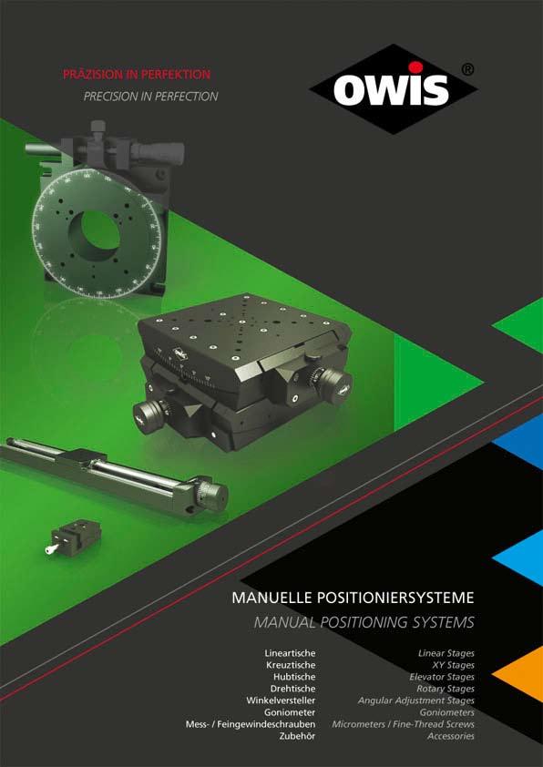
Manuelle Positioniersysteme Manual Positioning Systems
|
|
|
- Ella Baumann
- vor 6 Jahren
- Abrufe
Transkript
1
2 Manuelle Positioniersysteme Manual Positioning Systems Inhalt Drehtische...DT 40...P91 Drehtische...DT 65...P93 Drehtische...DT P95 Drehtische...DT 1...P97 Drehversteller...DV 65...P89 Feingewindeschrauben...FGS... P131 Feingewindeschrauben...FGS P135 Goniometer...GO 40...P105 Goniometer...NEU..GO P117 Goniometer...GO 65L... P111 Goniometer...GO 65S...P107 Goniometer...GO P113 Goniometer...NEU..GO P119 Goniometer, Theta-Phi-...TP 65...P109 Goniometer, Theta-Phi-...TP P115 Goniometer, Theta-Phi-...NEU..TP P115 Höhenverstelltische...HV 60...P81 Höhenverstelltische...HV P83 Höhenverstelltische, Präzisions-...HT...P85 Kreuztische...KT 65...P25 Kreuztische...KT 90...P31 Kreuztische...KT 1...P33 Kreuztische, Miniatur-...MKT...P3 Kreuztische, Miniatur-...MKT 40B...P7 Kreuztische, Miniatur-...MKT 40C...P13 Kreuztische, Miniatur- (unmagnetisch)...mkt 40B-UM...P19 Kreuztische, Präzisions-...PKT...P51 Kreuztische, Präzisions-...PKT 70...P51 Kreuztische, Präzisions-...PKT P55 Kreuztische, Präzisions-...PKT 1...P55 Kreuztische, unmagnetisch...kt 65-UM...P29 Lineartische, Präzisions-...LPT...P41 Lineartische, Präzisions-...LT 45...P43 Lineartische, Präzisions-...LT 60...P45 Lineartische, Präzisions-...LT 80...P47 Lineartische, Präzisions-...LT 1...P49 Messschrauben...MS... P125 Messschrauben...MS P127 Messschrauben, Differenzial-...MSD...P129 Messtische...MT...P59 Messtische...MT 45...P61 Content Angular Adjustment Stages...WV P99 Angular Adjustment Stages...WV 60...P101 Angular Adjustment Stages...WV P103 Elevator Stages...HV P81 Elevator Stages...HV P83 Elevator Stages, precision...ht... P85 Fine-Thread Screws...FGS...P131 Fine-Thread Screws...FGS 15...P135 Goniometers...GO 40...P105 Goniometers...NEW..GO P117 Goniometers...GO 65L... P111 Goniometers...GO 65S...P107 Goniometers...GO 90...P113 Goniometers...NEW..GO 1-...P119 Goniometers, theta-phi...tp P109 Goniometers, theta-phi...tp 90...P115 Goniometers, Theta-Phi-...NEW..TP P115 Linear Stages, precision...lpt...p41 Linear Stages, precision...lt P43 Linear Stages, precision...lt P45 Linear Stages, precision...lt P47 Linear Stages, precision...lt 1... P49 Measuring Stages...MT... P59 Measuring Stages...MT P61 Measuring Stages...MT... P65 Measuring Stages...MT P67 Measuring Stages...MT P73 Measuring Stages...MT 1... P77 Measuring Stages, non-magnetic...mt 60-UM... P71 Micrometers...MS...P125 Micrometers...MS 10...P127 Micrometers, differential...msd...p129 Positioning Systems Accessories...ZB...P137 Rotary Adjustment Stages...DV P89 Rotary Stages...DT P91 Rotary Stages...DT P93 Rotary Stages...DT P95 Rotary Stages...DT 1... P97 Translation Stages...NEW..VT... P37 Translation Stages...VT P39 Translation Stages...VT 65-XYZ... P27 P OWIS GmbH Im Gaisgraben Staufen i. Br. (Germany) Tel. +49 (0) / Fax +49 (0) / info@owis.eu mobile.owis.eu PI
3 Messtische...MT...P65 Messtische...MT 60...P67 Messtische...MT 75...P73 Messtische...MT 1...P77 Messtische, unmagnetisch...mt 60-UM...P71 Verschiebetische...NEU..VT...P37 Verschiebetische...VT 45...P39 Verschiebetische...VT 65-XYZ...P27 Verschiebetische...VT 65-Z...P23 Verschiebetische, Miniatur-...MVT -Z...P1 Verschiebetische, Miniatur-...MVT 40B-XYZ...P9 Verschiebetische, Miniatur-...MVT 40B-Z...P5 Verschiebetische, Miniatur-...MVT 40C-XYZ...P15 Verschiebetische, Miniatur-...MVT 40C-Z... P11 Verschiebetische, Miniatur-...VT 14...P35 Verschiebetische, Miniatur-... (unmagnetisch)...mvt 40B-Z-UM...P17 Winkelverstelltische...WV 40...P99 Winkelverstelltische...WV P101 Winkelverstelltische...WV P103 Zubehör Positioniersysteme...ZB... P137 Translation Stages...VT 65-Z... P23 Translation Stages, miniature...mvt -Z... P1 Translation Stages, miniature...mvt 40B-XYZ... P9 Translation Stages, miniature...mvt 40B-Z... P5 Translation Stages, miniature...mvt 40C-XYZ...P15 Translation Stages, miniature...mvt 40C-Z...P11 Translation Stages, miniature...vt P35 Translation Stages, miniature... (non-magnetic)...mvt 40B-Z-UM...P17 XY Stages...KT P25 XY Stages...KT P31 XY Stages...KT 1... P33 XY Stages, miniature...mkt... P3 XY Stages, miniature...mkt 40B... P7 XY Stages, miniature...mkt 40C...P13 XY Stages, miniature (non-magnetic)...mkt 40B-UM...P19 XY Stages, non-magnetic...kt 65-UM... P29 XY Stages, precision...pkt...p51 XY Stages, precision...pkt 70...P51 XY Stages, precision...pkt P55 XY Stages, precision...pkt 1... P55 Symbolerklärung: Zur Schnellsuche der passenden Produkte wurden einige Symbole in die Produktinformationen eingefügt. Symbol Legend: In order to rapidly find the corresponding products, some symbols have been added to the product information. 25 System SYS 25 kompatibel 40 System SYS 40 kompatibel 65 System SYS 65 kompatibel 90 System SYS 90 kompatibel 25 for use with system SYS for use with system SYS for use with system SYS for use with system SYS 90 Optionale unmagnetische Varianten V -6 Optionale vakuum präparierte Versionen optional non-magnetic versions V -6 optional vacuum-prepared versions PII Änderungen vorbehalten Copyright reserved by OWIS Subject to change without notice
4 Manuelle Positioniersysteme Manual Positioning Systems Typenbezeichnung DT Drehtische...P91 DT Drehtische...P93 DT Drehtische...P95 DT 1... Drehtische...P97 DV Drehversteller...P89 FGS... Feingewindeschrauben... P131 FGS Feingewindeschrauben... P135 GO Goniometer...P105 GO Goniometer... NEU..P117 GO 65L... Goniometer... P111 GO 65S... Goniometer...P107 GO Goniometer... P113 GO Goniometer... NEU..P119 HT... Höhenverstelltische, Präzisions-...P85 HV Höhenverstelltische...P81 HV Höhenverstelltische...P83 KT Kreuztische...P25 KT 65-UM... Kreuztische, unmagnetisch...p29 KT Kreuztische...P31 KT 1... Kreuztische...P33 LPT... Lineartische, Präzisions-...P41 LT Lineartische, Präzisions-...P43 LT Lineartische, Präzisions-...P45 LT Lineartische, Präzisions-...P47 LT 1... Lineartische, Präzisions-...P49 MKT... Kreuztische, Miniatur-...P3 MKT 40B... Kreuztische, Miniatur-...P7 MKT 40B-UM... Kreuztische, Miniatur- (unmagnetisch)...p19 MKT 40C... Kreuztische, Miniatur-...P13 MS... Messschrauben... P125 MS Messschrauben... P127 MSD... Messschrauben, Differenzial-...P129 MT... Messtische...P59 MT Messtische...P61 MT... Messtische...P65 MT Messtische...P67 MT 60-UM... Messtische, unmagnetisch...p71 MT Messtische...P73 MT 1... Messtische...P77 MVT -Z... Verschiebetische, Miniatur-...P1 MVT 40B-XYZ... Verschiebetische, Miniatur-...P9 MVT 40B-Z... Verschiebetische, Miniatur-...P5 Type designation DT Rotary Stages...P91 DT Rotary Stages...P93 DT Rotary Stages...P95 DT 1... Rotary Stages...P97 DV Rotary Adjustment Stages...P89 FGS... Fine-Thread Screws... P131 FGS Fine-Thread Screws... P135 GO Goniometers...P105 GO Goniometers...NEW..P117 GO 65L... Goniometers... P111 GO 65S... Goniometers...P107 GO Goniometers... P113 GO Goniometers... NEW..P119 HT... Elevator Stages, precision...p85 HV Elevator Stages...P81 HV Elevator Stages...P83 KT XY Stages...P25 KT 65-UM... XY Stages, non-magnetic...p29 KT XY Stages...P31 KT 1... XY Stages...P33 LPT... Linear Stages, precision...p41 LT Linear Stages, precision...p43 LT Linear Stages, precision...p45 LT Linear Stages, precision...p47 LT 1... Linear Stages, precision...p49 MKT... XY Stages, miniature...p3 MKT 40B... XY Stages, miniature...p7 MKT 40B-UM... XY Stages, miniature (non-magnetic)...p19 MKT 40C... XY Stages, miniature...p13 MS... Micrometers... P125 MS Micrometers... P127 MSD... Micrometers, differential...p129 MT... Measuring Stages...P59 MT Measuring Stages...P61 MT... Measuring Stages...P65 MT Measuring Stages...P67 MT 60-UM... Measuring Stages, non-magnetic...p71 MT Measuring Stages...P73 MT 1... Measuring Stages...P77 MVT -Z... Translation Stages, miniature...p1 MVT 40B-XYZ... Translation Stages, miniature...p9 MVT 40B-Z... Translation Stages, miniature...p5 P OWIS GmbH Im Gaisgraben Staufen i. Br. (Germany) Tel. +49 (0) / Fax +49 (0) / info@owis.eu mobile.owis.eu PIII
5 MVT 40B-Z-UM... Verschiebetische, Miniatur (unmagnetisch)...p17 MVT 40C-XYZ... Verschiebetische, Miniatur-...P15 MVT 40C-Z... Verschiebetische, Miniatur-... P11 PKT... Kreuztische, Präzisions-...P51 PKT Kreuztische, Präzisions-...P51 PKT Kreuztische, Präzisions-...P55 PKT 1... Kreuztische, Präzisions-...P55 TP Goniometer, Theta-Phi-...P109 TP Goniometer, Theta-Phi-... P115 TP Goniometers, Theta-Phi-... NEU..P123 VT Verschiebetische, Miniatur-...P35 VT... Verschiebetische...NEU..P37 VT Verschiebetische...P39 VT 65-XYZ... Verschiebetische...P27 VT 65-Z... Verschiebetische...P23 WV Winkelverstelltische...P99 WV Winkelverstelltische... P101 WV Winkelverstelltische...P103 ZB... Zubehör Positioniersysteme... P137 MVT 40B-Z-UM... Translation Stages, miniature (non-magnetic)...p17 MVT 40C-XYZ... Translation Stages, miniature...p15 MVT 40C-Z... Translation Stages, miniature... P11 PKT... XY Stages, precision...p51 PKT XY Stages, precision...p51 PKT XY Stages, precision...p55 PKT 1... XY Stages, precision...p55 TP Goniometers, theta-phi...p109 TP Goniometers, theta-phi... P115 TP Goniometers, theta-phi... NEW..P123 VT Translation Stages, miniature...p35 VT... Translation Stages...NEW..P37 VT Translation Stages...P37 VT 65-XYZ... Translation Stages...P27 VT 65-Z... Translation Stages...P23 WV Angular Adjustment Stages...P99 WV Angular Adjustment Stages... P101 WV Angular Adjustment Stages...P103 ZB... Positioning Systems Accessories... P137 Symbolerklärung: Zur Schnellsuche der passenden Produkte wurden einige Symbole in die Produktinformationen eingefügt. Symbol Legend: In order to rapidly find the corresponding products, some symbols have been added to the product information. 25 System SYS 25 kompatibel 40 System SYS 40 kompatibel 65 System SYS 65 kompatibel 90 System SYS 90 kompatibel 25 for use with system SYS for use with system SYS for use with system SYS for use with system SYS 90 Optionale unmagnetische Varianten V -6 Optionale vakuum präparierte Versionen optional non-magnetic versions V -6 optional vacuum-prepared versions PIV Änderungen vorbehalten Copyright reserved by OWIS Subject to change without notice
 Tel. +49 (0) 76 33 / 95 04-0 Fax +49 (0) 76 33 / 95 04-440 info@owis.eu www.owis.eu mobile.owis.eu PV")
6 Manuelle Positioniersysteme Manual Positioning Systems P OWIS GmbH Im Gaisgraben Staufen i. Br. (Germany) Tel. +49 (0) / Fax +49 (0) / info@owis.eu mobile.owis.eu PV
7 OWIS Positioniersysteme sind die ökonomische Lösung für Anwendungen, bei denen einfache aber präzise Bewegungsabläufe realisiert werden müssen. Durch die mannigfachen Kombinations möglich keiten der Linear-, Rotations-, Winkelverstell- und Neigetische, Goniometer sowie der Feingewinde- und Messschrauben in unterschiedlichsten Spezifikationen, wird ein großer Einsatzbereich abgedeckt. Adapter platten ermöglichen zusätzlich viele Zusammenbaumöglichkeiten. Daher ist eine Vielzahl von Anwendungen auch außerhalb der standardisierten Systemhöhen 25 mm (SYS 25), 40 mm (SYS 40), 65 mm (SYS 65) und 105 mm (SYS 90) realisierbar. Verschiebetische mit Schwalbenschwanzführungen stellen die optimale Lösung für eine Vielzahl von translatorischen Positionieraufgaben dar. Sie besitzen neben klaren preislichen Vorteilen gegenüber Messtischen mit Wälzkörperführungen auch einige funktionelle Vorteile. Schwalbenschwanzführungen können generell sehr hohe Kräfte und Momente aufnehmen, sie sind beständiger gegenüber Vibrationen, und sie lassen sich ohne weitere Hilfsmittel dauerhaft klemmen. Damit sind sie für einmalige Einstellaufgaben in Maschinen und Geräten prädestiniert. Durch modernste Fertigung und langjährige Erfahrung genügen OWIS Verschiebetische höchsten Qualitätsanforderungen. In Kombination mit Präzisions-Feingewindespindeln sind Einstellungen im Mikrometerbereich möglich. Der Gleitführungen eigene slip-stick- Effekt wird durch eine spezielle Schmierung weitgehend eliminiert. Alle Verschiebetische mit Feingewindespindel sind bidirektional gleich stark belastbar. Bei Tischen mit Feingewindeschraube oder Messschraube ist auf die richtige Einbaulage bezüglich der angreifenden Kräfte zu achten. Alle Verschiebetische sind ohne zusätzliche Montagewinkel zu XY-, XZ- und XYZ-Anordnungen kombinierbar. Verschiebetische mit zentraler Öffnung kommen vor allem in Form von Kreuztischen mit integriertem Schieber für die X- und Y-Bewegung zum Einsatz. Durch diese Anordnung besitzen sie eine geringere Bauhöhe als Kombinationen zweier Einzeltische. Sie werden häufig zur Justierung optischer Elemente im Strahlengang verwendet. Dazu besitzen sie eine möglichst große zentrale Öffnung bei relativ geringen Verfahrwegen. Eine Demontage von Kreuztischen in zwei einzelne Verschiebetische ist nicht möglich. Messtische werden mit vorgespannten Wälzkörperführungen geliefert, die eine slip-stick- und praktisch spielfreie Bewegung des Schlittens gewährleisten. Die Schlittenposition wird mit Messschrauben verstellt und kann somit direkt abgelesen werden. Die Spielfreiheit der Linearbewegung wird durch Rückstellfedern erreicht. Die eingesetzten Messschrauben mit 0,25 mm oder 0,5 mm Steigung besitzen Skalenteilungen von 5 µm bzw. 10 µm. Die Einstellempfind lichkeit beträgt 1 µm bis 2 µm. Nahezu alle Messtische können mit Stellantrieben (DC- oder Schrittmotor) ausgestattet werden. Alle Messtische sind ohne zusätzliche Montagewinkel zu XY-, XZund XYZ-Anordnungen kombinierbar. OWIS positioning systems are the economic solution for applications, where simple but precise motion sequences have to be realized. Due to the manifold combination possibilities of linear, rotary, angular adjustment and tilt stages, goniometers as well as fine-thread and micrometer screws in the most different specifications, a large application area is covered. Adapter plates allow additional assembling possibilities. Therefore, a multitude of applications is possible, also beyond the standardized system heights of 25 mm (SYS 25), 40 mm (SYS 40), 65 mm (SYS 65) and 105 mm (SYS 90). Translation stages with dovetail guides are the ideal solution for numerous translational positioning tasks. Besides their clear advantage in cost compared to measurement stages with roller bearing guides, they also have a few functional advantages. Dovetail guides can generally withstand very strong forces and torques, they are more stable against vibrations, and they can remain clamped for a long time without any special tools. Therefore, they are the ideal solution for one-time adjustment in machines and devices. OWIS translation stages meet the highest demands on quality through modern production and years of experience. In combination with precision fine-thread spindles, they can accommodate adjustments in the micrometer range. The slip-stick effect characteristic of the sliding guides can be to a large extent eliminated with a special lubricant. All translation stages with fine-thread spindles can bear large loads in both directions. In order to correctly adjust the stages with fine-thread screws or micrometers the applied forces should be considered. All translation stages can be combined in XY, XZ, and XYZ configurations without additional mounting angles. Translation stages with central opening are mostly used as XY stages with integrated slides for movement along the X and Y axes. Due to this configuration, they are lower in height than combinations of two individual stages. They are frequently used for adjusting optical elements in the beam path. For this reason, they have a large central opening with relatively short travel. XY stages cannot be disassembled to form separate translation stages. Measuring stages are available with backlash-free, prestressed roller bearing guides which ensure practically slip-stick free movement of the slide. The slide position can be adjusted with micrometer screws and can, therefore, be read directly. The micrometer screws with a pitch of 0.25 mm or 0.5 mm are graduated by 5 µm and/or 10 µm. Adjustment sensitivity is 1 µm to 2 µm for manual adjustments. Nearly all manual measuring stages can be equipped with DC or step motors. All measuring stages can be combined to XY, XZ and XYZ configurations without additional mounting brackets. PVI Änderungen vorbehalten Copyright reserved by OWIS Subject to change without notice
8 Definition der X-, Y- und Z-Achse Die untere Achse ist immer die X-Achse, die horizontal verfährt. Darauf folgt die Y-Achse, die von vorne nach hinten verfährt. Die Z-Achse verfährt von unten nach oben (Bild 1). Definition of the X-, Y- and Z Axis The lower axis is always the X axis which travels horizontaly. Thereon is the Y axis which travels from the front backwards. The Z axis travels from the bottom up (see fig. 1). Bild/fig. 1 Spezialfall: Strahlführung Die optische Achse ist hier die Z-Achse. X- und Y-Achse ergeben sich hieraus wie folgt (Bild 2): Special Case: Beam Handling Systems The optical axis is the Z axis. X and Y axis result as follow (see fig. 2): Bild/fig. 2 Einbaulage In den Zeichnungen sind jeweils kleine Skizzen in den üblichen Einbaulagen abgebildet. Technische Daten Alle technischen Daten sind abhängig von Einbaulage und Anwendung. Die Werte beziehen sich auf eine Umgebungstemperatur von C, ohne Last. Umrechnung: 1 µrad = 0,21 arcsec 1 mrad = 3,44 arcmin 1 rad = 57, Orientation A small drawing with the typical orientations is given in the graph. Technical Data All technical data depend on orientation and application. They relate on an ambient temperature of C, no load. Conversion: 1 µrad = 0.21 arcsec 1 mrad = 3.44 arcmin 1 rad = 57. PVII
9 PVIII Änderungen vorbehalten Copyright reserved by OWIS Subject to change without notice

10 PRODUKTINFORMATION PRODUCT INFORMATION Miniaturverschiebetische Miniature Translation Stages SYS 40 kompatibel verzugsarmes Aluminium reflexionsarm, schwarz eloxiert mit Feingewindespindel kompakte Bauweise geringe Masse Montagemöglichkeiten auf Reiter auf Stift for use with SYS 40 deformation-resistant aluminium reflection-poor, black anodized with fine-thread spindle compact design low mass ways of installing on slide on pin V -6 X X MVT -Z / Die Miniaturverschiebetische MVT -Z sind für Justieraufgaben auf kleinstem Raum bestimmt. Bei einer Kantenlänge von nur mm ermöglichen sie bei 3 mm (±1,5 mm) Stellweg einen freien Durchgang von 7 mm. Die MVT -Z werden mit Feingewindespindeln und Skalenknopf geliefert. Durch die Zwangsrückstellung des Schiebers sind sie bidirektional gleich stark belastbar. Die Miniaturverschiebetische MVT -Z mit Stiftadapterplatte auf Reiter RT 40 haben die Strahlhöhe des SYS 40. The MVT -Z miniature translation stages are made for adjustment tasks in smallest areas. With an edge length of only mm, they provide an opening of 7 mm for the complete travel range of 3 mm (±1.5 mm). The MVT -Z are supplied with fine-thread spindles and a graduated button. They can bear equally large loads in both directions thanks to forced return travel of the slide. The MVT -Z miniature translation stages with the pin adapter plate mounted on slides RT 40 have the beam height of the SYS 40. Bestellangaben/Ordering Information Miniaturverschiebetische/miniature translation stages mit Stiftadapterplatte with pin adapter plate MVT -D10-Z-S mit Endplatte with end plate MVT -D10-Z-EP Zubehör/Accessories Stift 15 pin 15 s. Produktinfo STF 15 / s. product info STF 15 Reiter RT 40, mm, mit Rändelschraube slide RT 40, mm, with knurled screw RT 40--R OWIS GmbH Im Gaisgraben Staufen i. Br. (Germany) Tel. +49 (0) / Fax +49 (0) / info@owis.eu mobile.owis.eu P1
11 M6 8 MVT -D10-Z-S Bei Reitermontage M2,5 x 8 durch M2,5 x 14 ersetzen mounting on slide replace M2.5 x 8 by M2.5 x 14 Ø ,7 24 Ø 3 3 MVT -D10-Z-S 16 M3 4 M RT 40 S 40 LL Ø , Ø M M3 4 Ø 3 3 MVT -D10-Z-EP 14 Ø 10 MVT -D10-Z-EP Technische Daten/Technical Data MVT -Z Stellweg travel 3 (±1,5) mm Spindelsteigung spindle pitch 0,25 mm Skalenteilung graduation of scale 5 µm Einstellempfindlichkeit setting sensitivity 1 µm freier Durchgang size of opening ø 7-10 mm Tragfähigkeit maximum load capacity 90 N Lastmoment load torque 1,5 Nm Rückstellkraft reset force 6 bis/up to14 N Gewicht weight 60 g P2 Änderungen vorbehalten Copyright reserved by OWIS Subject to change without notice
12 PRODUKTINFORMATION PRODUCT INFORMATION Miniaturkreuztische Miniature XY Stages SYS 40 kompatibel verzugsarmes Aluminium reflexionsarm, schwarz eloxiert mit Feingewindespindel kompakte Bauweise geringe Masse Montagemöglichkeiten auf Reiter auf Stift for use with SYS 40 deformation-resistant aluminium reflection-poor, black anodized with fine-thread spindle compact design low mass ways of installing on slide on pin V -6 X X MKT / Die Miniaturkreuztische MKT sind für Justieraufgaben auf kleinstem Raum bestimmt. Bei einer Kantenlänge von nur mm ermöglichen sie bei 3 mm (±1,5 mm) Stellweg einen freien Durchgang von 7 mm. Die MKT werden mit Feingewindespindeln und Skalenknopf geliefert. Durch die Zwangsrückstellung des Schiebers sind sie bidirektional gleich stark belastbar. Die Miniaturkreuztische MKT -D10-S auf Reiter RT 40 haben die Strahlhöhe des SYS 40. The MKT miniature XY stages are made for adjustment tasks in smallest areas. With an edge length of only mm, they provide an opening of 7 mm for the complete travel range of 3 mm (±1.5 mm). The MKT are supplied with fine-thread spindles and a graduated button. They can bear equally large loads in both directions thanks to forced return travel of the slide. The MKT -D10-S miniature XY stages mounted on slides RT 40 have the beam height of the SYS 40. Bestellangaben/Ordering Information Miniaturkreuztische/miniature XY stages auf Reiter RT 40--R on slide RT 40--R MKT -D10-RT mit Stiftadapterplatte with pin adapter plate MKT -D10-S mit Endplatte with end plate MKT -D10-EP Zubehör/Accessories Stift 15 pin 15 s. Produktinfo STF 15 / s. product info STF 15 Reiter RT 40, mm, mit Rändelschraube slide RT 40, mm, with knurled screw RT 40--R OWIS GmbH Im Gaisgraben Staufen i. Br. (Germany) Tel. +49 (0) / Fax +49 (0) / info@owis.eu mobile.owis.eu P3
13 22,6 24 MKT -D10-RT M Ø 3 3 MKT -D10-RT40 S 40 LL Ø 10 Ø ,8 16 M3 4 M6 8 MKT -D10-S 36 22, M3 4 Ø 3 3 MKT -D10-S Ø 3 3 Ø M ,6 24 MKT -D10-EP M3 4 Ø 3 3 Ø 3 3 Ø M3 4 MKT -D10-EP Technische Daten/Technical Data MKT Stellweg travel 3 (±1,5) mm Spindelsteigung spindle pitch 0,25 mm Skalenteilung graduation of scale 5 µm Einstellempfindlichkeit setting sensitivity 1 µm freier Durchgang size of opening ø 7-10 mm Tragfähigkeit maximum load capacity 90 N Lastmoment load torque 1,5 Nm Rückstellkraft reset force 6 bis/up to14 N Gewicht weight 110 g P4 Änderungen vorbehalten Copyright reserved by OWIS Subject to change without notice
14 PRODUKTINFORMATION PRODUCT INFORMATION Miniaturverschiebetische Miniature Translation Stages SYS 40 kompatibel verzugsarmes Aluminium reflexionsarm, schwarz eloxiert mit Feingewindespindel kompakte Bauweise geringe Masse Montagemöglichkeiten auf Reiter auf Stift for use with SYS 40 deformation-resistant aluminium reflection-poor, black anodized with fine-thread spindle compact design low mass ways of installing on slide on pin V -6 X X MVT 40B-Z / Die Miniaturverschiebetische MVT 40B-Z sind mit Federn spielfrei vorgespannt. Eine Feingewindespindel mit Skalenknopf ermöglicht feinfühliges Einstellen. Die justier baren Schwalbenschwanz führungen behalten ihre Genauigkeit über sehr lange Zeit. Die MVT 40B-Z sind SYS 40 kompatibel auf Reitern RT 40. The MVT 40B-Z miniature translation stages are preloaded with springs and therefore backlash-free. A fine-thread spindle enables sensitive adjustment. The dovetail guides are adjustable and maintain their accuracy over very long time. The MVT 40B-Z are SYS 40 compatible, when mounted on slide RT 40. Bestellangaben/Ordering Information Miniaturverschiebetische/miniature translation stages ohne Reiter/Endplatte without slide/end plate MVT 40B-D15-Z-SK mit Endplatte with end plate MVT 40B-D15-Z-SK-EP Zubehör/Accessories Reiter RT 40, 16 mm, für MVT 40, MKT 40, KTM 40 slide RT 40, 16 mm, for MVT 40, MKT 40, KTM 40 RT R-MVT Reiter RT 40, mm, mit Rändelschraube slide RT 40, mm, with knurled screw RT 40--R Stiftadapter für MVT 40(B), MKT 40 und WV 40 pin adapter for MVT 40(B), MKT 40 and WV 40 ADP 40-DTF OWIS GmbH Im Gaisgraben Staufen i. Br. (Germany) Tel. +49 (0) / Fax +49 (0) / info@owis.eu mobile.owis.eu P5
15 MVT 40B-D15-Z-SK 2,8 M3 5 - Snkg. f. M2,5 M3 5 - cntrb. f. M2.5 M3 5 - Snkg. f. M2,5 84 M3 5 - cntrb. f. M MVT 40B-D15-Z-SK Ø 3 3 S 40 LL 38 Ø Ø 15 Ø 15 M2,5 4 Ø 2 4 RT 40 14,3 14, ,5 12, M2,3 4 21,2 Ø 21 M2,3 4 21,2 Ø 21 Ø ,5 Snkg. f. M2,5 cntrb. f. M2.5 Ø ,5 M3 4 - Snkg. f. M2,5 M3 4 - cntrb. f. M2.5 Snkg. f. M2,5 cntrb. f. M2.5 MVT 40B-D15-Z-SK-EP M3 4 - Snkg. f. M2,5 M3 4 - cntrb. f. M2.5 32,5 S 40 LL RT 40 MVT 40B-D15-Z-SK-EP Technische Daten/Technical Data MVT 40B-Z Stellweg travel 6 (±3) mm Spindelsteigung spindle pitch 0,25 mm Skalenteilung graduation of scale 5 µm Einstellempfindlichkeit setting sensitivity 1 µm freier Durchgang size of opening ø 15 mm Tragfähigkeit maximum load capacity 1 N Lastmoment load torque 2,5 Nm Axiallast axial load 60 N Rückstellkraft reset force 7 bis/up to 19 N Gewicht weight 95 g P6 Änderungen vorbehalten Copyright reserved by OWIS Subject to change without notice

16 PRODUKTINFORMATION PRODUCT INFORMATION Miniaturkreuztische Miniature XY Stages SYS 40 kompatibel verzugsarmes Aluminium reflexionsarm, schwarz eloxiert mit Feingewindespindel kompakte Bauweise geringe Masse Montagemöglichkeiten auf Reiter auf Stift for use with SYS 40 deformation-resistant aluminium reflection-poor, black anodized with fine-thread spindle compact design low mass ways of installing on slide on pin V -6 X X MKT 40B / Die Miniaturkreuztische MKT 40B sind mit Federn spielfrei vorgespannt. Die Feingewindespindeln mit Skalenknopf ermög lichen feinfühliges Einstellen. Die justier baren Schwalben schwanz führungen behalten ihre Genauigkeit über sehr lange Zeit. Die MKT 40B sind SYS 40 kompatibel auf Reitern RT 40 und die Versionen mit Transjustierungen können gefasste Optiken mit ø 25 mm aufnehmen. The MKT 40B miniature XY stages are preloaded with springs and therefore backlash-free. The fine-thread spindles with graduated button enables sensitive adjustment. The dovetail guides are adjustable and maintain their accuracy over very long time. The MKT 40B are for use with SYS 40, when mounted on slide RT 40, and the versions with transmitting mount can carry mounted optics with ø 25 mm. Bestellangaben/Ordering Information Miniaturkreuztische/miniature XY stages ohne Endplatte without end plate ohne Transjustierung without transmitting mount MKT 40B-D15-SK mit Transjustierung mit Feingewindeschrauben with transmitting mount with fine-thread screws MKT 40B-TRANS40-FGS mit Transjustierung mit Messschrauben with transmitting mount with micrometers MKT 40B-TRANS40-MS mit Transjustierung mit Tellerfedern with transmitting mount with disc springs MKT 40B-TRANS40-T mit Transjustierung mit Feingewindeschrauben und Z-Verstellung with transmitting mount with fine-thread screws and Z adjustment MKT 40B-TRANS40-FGS-Z mit Endplatte with end plate ohne Transjustierung without transmitting mount MKT 40B-D15-SK-EP mit Transjustierung mit Feingewindeschrauben with transmitting mount with fine-thread screws MKT 40B-TRANS40-FGS-EP mit Transjustierung mit Messschrauben with transmitting mount with micrometers MKT 40B-TRANS40-MS-EP mit Transjustierung mit Tellerfedern with transmitting mount with disc springs MKT 40B-TRANS40-T-EP mit Transjustierung mit Feingewindeschrauben und Z-Verstellung with transmitting mount with fine-thread screws and Z adjustment MKT 40B-TRANS40-FGS-Z-EP Zubehör/Accessories Reiter RT 40, 16 mm, für MVT 40, MKT 40, KTM 40 slide RT 40, 16 mm, for MVT 40, MKT 40, KTM 40 RT R-MVT Stiftadapter für MVT 40(B), MKT 40 und WV 40 pin adapter for MVT 40(B), MKT 40 and WV 40 ADP 40-DTF Aufnahmeplatte MKT 40 für ø25 mm mounting plate MKT 40 for ø25 mm OH 40-D25-LTD40B Aufnahmeplatte MKT 40 für ø1" mounting plate MKT 40 for ø1" OH 40-D26-LTD40B OWIS GmbH Im Gaisgraben Staufen i. Br. (Germany) Tel. +49 (0) / Fax +49 (0) / info@owis.eu mobile.owis.eu P7
17 38 Ø 2 4 M2,5 4 MKT 40B-D15-SK MKT 40B-TRANS40-FGS MKT 40B-TRANS40-MS MKT 40B-TRANS40-T MKT 40B-TRANS40-FGS-Z 2,8 M2,3 4 21,2 Ø 21 Ø Snkg. f. M2,5 cntrb. f. M , Ø 2 4 M3 4 - Snkg. f. M2,5 M3 4 - cntrb. f. M2.5 21,2 M2,3 4 M3 4 - Snkg. f. M2,5 M3 4 - cntrb. f. M2.5 Ø (TRANS40-T) 1014,5 Snkg. f. M2,5 cntrb. f. M2.5 MKT 40B-XXXXXXX-XXX-X 63,7 MKT 40B-D15-SK-EP MKT 40B-TRANS40-FGS-EP MKT 40B-TRANS40-MS-EP MKT 40B-TRANS40-T-EP MKT 40B-TRANS40-FGS-Z-EP 38 M2,3 4 21,2 Ø 21 Ø Snkg. f. M2,5 cntrb. f. M , Ø 2 4 M3 4 - Snkg. f. M2,5 M3 4 - cntrb. f. M2.5 21,2 M2,3 4 M3 4 - Snkg. f. M2,5 M3 4 - cntrb. f. M2.5 Ø (TRANS40-T) 10 14,5 Snkg. f. M2,5 cntrb. f. M2.5 MKT 40B-XXXXXXX-XXX-XX 63,7 Technische Daten/Technical Data MKT 40B Stellweg travel 6 (±3) mm Spindelsteigung spindle pitch 0,25 mm Skalenteilung graduation of scale 5 µm Einstellempfindlichkeit setting sensitivity 1 µm freier Durchgang size of opening ø 15 mm Tragfähigkeit maximum load capacity 1 N Lastmoment load torque 2,5 Nm Axiallast axial load 60 N Rückstellkraft reset force 7 bis/up to 19 N Gewicht weight 5 g P8 Änderungen vorbehalten Copyright reserved by OWIS Subject to change without notice

18 PRODUKTINFORMATION PRODUCT INFORMATION Miniaturverschiebetische Miniature Translation Stages SYS 40 kompatibel verzugsarmes Aluminium reflexionsarm, schwarz eloxiert mit Feingewindespindel kompakte Bauweise geringe Masse Montagemöglichkeiten auf Reiter auf Stift for use with SYS 40 deformation-resistant aluminium reflection-poor, black anodized with fine-thread spindle compact design low mass ways of installing on slide on pin V -6 X X MVT 40B-XYZ / Die Miniaturverschiebetische MVT 40B-XYZ sind mit Federn spielfrei vorgespannt. Die Feingewindespindeln mit Skalenknopf ermöglichen feinfühliges Einstellen. Die justier baren Schwalben schwanz führungen behalten ihre Genauigkeit über sehr lange Zeit. Die MVT 40B-D15-XYZ-SK sind SYS 40 kompatibel auf Reiter RT 40. Eine Integration in SYS 65 auf Anfrage. Die MVT 40B-D15-XYZ-SK sind 3-Achs-Kombinationen, wobei die Z-Achse mit dem Schieber nach innen montiert ist. The MVT 40B-XYZ miniature translation stages are preloaded with springs and therefore backlash-free. Fine-thread spindles with graduated button enable sensitive adjustment. The dovetail guides are adjustable and maintain their accuracy over very long time. The MVT 40B-D15-XYZ-SK are for use with SYS 40, when mounted on slide RT 40. Integration for use with SYS 65 on request. The MVT 40B-D15-XYZ-SK are 3-axis combinations, where the Z axis is assembled with inwards slide. Bestellangaben/Ordering Information Miniaturverschiebetische/miniature translation stages mit Endplatten with end plates MVT 40B-D15-XYZ-SK-EP für SYS 40 for SYS 40 MVT 40B-D15-XYZ-SK Zubehör/Accessories Aufnahmeplatte MKT 40 für ø 25 mm, mounting plate MKT 40 for ø 25 mm, OH 40-D25-LTD40B nur für only for Aufnahmeplatte MKT 40 für ø 1, mounting plate MKT 40 for ø 1, OH 40-D26-LTD40B nur für only for Reiter RT 40, mm, mit Rändelschraube slide RT 40, mm, with knurled screw RT 40--R OWIS GmbH Im Gaisgraben Staufen i. Br. (Germany) Tel. +49 (0) / Fax +49 (0) / info@owis.eu mobile.owis.eu P9
19 MVT 40B-D15-XYZ-SK-EP 21,2 Snkg. f. M2,5 cntrb. f. M2.5 M2, ,5 M3 4 - Snkg. f. M2,5 M3 4 - cntrb. f. M2.5 12,5 0,3 14,3 Ø Ø Ø 15 M3 5 - Snkg. f. M2,5 M3 5 - cntrb. f. M MVT 40B-D15-XYZ-SK-EP MVT 40B-D15-XYZ-SK Ø M3 4 - Snkg. f. M2,5 M3 4 - cntrb. f. M2.5 21,2 M2, ,5 Ø 2 4 Snkg. f. M2,5 cntrb. f. M2.5 M3 5 - Snkg. f. M2,5 M3 5 - cntrb. f. M , ,2 RT 40 Ø 15 Ø S 40 LL RT 40 S 40 LL 40 S 40 LL 38 RT 40 MVT 40B-D15-XYZ-SK Technische Daten/Technical Data MVT 40B-XYZ Stellweg travel 6 (±3) mm Spindelsteigung spindle pitch 0,25 mm Skalenteilung graduation of scale 5 µm Einstellempfindlichkeit setting sensitivity 1 µm freier Durchgang size of opening max. ø 15 mm Tragfähigkeit maximum load capacity 1 N Lastmoment load torque 2,5 Nm Axiallast axial load 60 N Rückstellkraft reset force 7 bis/up to 19 N Gewicht weight 2 g P10 Änderungen vorbehalten Copyright reserved by OWIS Subject to change without notice

20 PRODUKTINFORMATION PRODUCT INFORMATION Miniaturverschiebetische Miniature Translation Stages SYS 40 kompatibel verzugsarmes Aluminium reflexionsarm, schwarz eloxiert mit Feingewindeoder Messschraube flache Bauweise geringe Masse Montagemöglichkeiten auf Reiter auf Stift for use with SYS 40 deformation-resistant aluminium reflection-poor, black anodized with fine-thread screw or micrometer flat design low mass ways of installing on slide on pin V -6 X X MVT 40C-Z / Die Miniaturverschiebetische MVT 40C-Z wurden im Hinblick auf eine möglichst flache Bauform optimiert und sind wahlweise mit Feingewindeschraube oder mit Messschraube erhältlich. Das Umkehrspiel ist über Federrückstellung minimiert. The MVT 40C-Z miniature translation stages have been optimized regarding their flat form and are alternativly available with fine-thread screw or with micrometer. The backlash is minimized through the spring return. Bestellangaben/Ordering Information Miniaturverschiebetische/miniature translation stages MVT 40C-Z-FGS-RT mit Feingewindeschraube, auf Reiter RT R-MVT 40 with fine-thread screw, on slide RT R-MVT 40 mit Feingewindeschraube, mit Stiftadapterplatte with fine-thread screw, with pin adapter plate MVT 40C-Z-FGS-STAP mit Feingewindeschraube, mit Endplatte with fine-thread screw, with end plate MVT 40C-Z-FGS-EP mit Feingewindeschraube, auf Reiter RT 40--R with fine-thread screw, on slide RT 40--R MVT 40C-Z-FGS-RT mit Messschraube, with micrometer, MVT 40C-Z-MS-RT auf Reiter RT R-MVT 40 on slide RT R-MVT 40 mit Messschraube, mit Stiftadapterplatte with micrometer, with pin adapter plate MVT 40C-Z-MS-STAP mit Messschraube, mit Endplatte with micrometer, with end plate MVT 40C-Z-MS-EP mit Messschraube, auf Reiter RT 40--R with micrometer, on slide RT 40--R MVT 40C-Z-MS-RT Zubehör/Accessories Stift 15 pin 15 s. Produktinfo STF 15 / s. product info STF 15 OWIS GmbH Im Gaisgraben Staufen i. Br. (Germany) Tel. +49 (0) / Fax +49 (0) / info@owis.eu mobile.owis.eu P11
21 MVT 40C-Z-FGS-RT MVT 40C-Z-MS-RT MVT 40C-Z-FGS-STAP MVT 40C-Z-MS-STAP 21,2 Snkg. f. M2,5 cntrb. f. M2.5 Ø ,5 Ø 15 Ø 3 3 M ,4 M6 10 M2,3 4 Ø 21 S 40 LL 38 51,2 1014,5 78 M3 4 - Snkg. f. M2,5 M3 4 - cntrb. f. M S 40 LL 92, S 40 LL 19 M3 5 - Snkg. f. M2,5 M3 5 - cntrb. f. M2.5 51,8 38 M2,3 4 Snkg. f. M2,5 cntrb. f. M2.5 Ø 21 21,2 Ø ,5 70, ,5 M3 5 - Snkg. f. M2,5 M3 5 - cntrb. f. M ,5 Ø 3 3 Ø 15 32,5 MVT 40C-Z-XXX-RT40-16 MVT 40C-Z-XXX-STAP M3 4 - Snkg. f. M2,5 M3 4 - cntrb. f. M2.5 MVT 40C-Z-FGS-EP MVT 40C-Z-MS-EP MVT 40C-Z-FGS-RT 40- MVT 40C-Z-MS-RT 40- M2,3 4 Snkg. f. M2,5 cntrb. f. M2.5 Ø 21 21,2 Ø ,5 12, ,5 49 M3 4 - Snkg. f. M2,5 M3 4 - cntrb. f. M Ø15 M3 5 - Snkg. f. M2,5 M3 5 - cntrb. f. M2.5 Ø ,5 M2,3 4 14,510 21,2 52,2 38 S 40 LL Ø ,5 M3 4 - Snkg. f. M2,5 M3 4 - cntrb. f. M2.5 Snkg. f. M2,5 cntrb. f. M2.5 MVT 40C-Z-XXX-EP MVT 40C-Z-XXX-RT40- Technische Daten/Technical Data MVT 40C-Z Stellweg travel 6 (±3) mm Spindelsteigung spindle pitch 0,25 mm Skalenteilung graduation of scale 5 µm Einstellempfindlichkeit setting sensitivity 1 µm freier Durchgang size of opening ø 15 mm Tragfähigkeit maximum load capacity 1 N Lastmoment load torque 2,5 Nm Rückstellkraft reset force 11 bis/up to 24 N Gewicht weight 1 g P12 Änderungen vorbehalten Copyright reserved by OWIS Subject to change without notice
22 PRODUKTINFORMATION PRODUCT INFORMATION Miniaturkreuztische Miniature XY Stages SYS 40 kompatibel verzugsarmes Aluminium reflexionsarm, schwarz eloxiert mit Feingewindeoder Messschrauben flache Bauweise geringe Masse Montagemöglichkeiten auf Reiter auf Stift for use with SYS 40 deformation-resistant aluminium reflection-poor, black anodized with fine-thread screws or micrometers flat design low mass ways of installing on slide on pin V -6 X X MKT 40C / Die Miniaturkreuztische MKT 40C wurden im Hinblick auf eine möglichst flache Bauform optimiert und sind wahlweise mit Feingewindeschrauben oder mit Messschrauben erhältlich. Das Umkehrspiel ist über Federrückstellung minimiert. The MKT 40C miniature XY stages have been optimized regarding their flat form and are alternativly available with fine-thread screws or with micrometers. The backlash is minimized through the spring return. Bestellangaben/Ordering Information Miniaturkreuztische/miniature XY stages mit Feingewindeschrauben, auf Reiter RT R with fine-thread screws, on slide RT R MKT 40C-FGS-RT mit Feingewindeschrauben, mit Stiftadapterplatte with fine-thread screws, with pin adapter plate MKT 40C-FGS-STAP mit Feingewindeschrauben, mit Endpatte with fine-thread screws, with end plate MKT 40C-FGS-EP mit Messschrauben, auf Reiter RT R with micrometers, on slide RT R MKT 40C-MS-RT mit Messschrauben, mit Stiftadapterplatte with micrometer, with pin adapter plate MKT 40C-MS-STAP mit Messschrauben, mit Endplatte with micrometers, with end plate MKT 40C-MS-EP Zubehör/Accessories Aufnahmeplatte MKT 40 für ø 25 mm mounting plate MKT 40 for ø 25 mm OH 40-D25-LTD40B Aufnahmeplatte MKT 40 für ø 1 mounting plate MKT 40 for ø 1 OH 40-D26-LTD40B OWIS GmbH Im Gaisgraben Staufen i. Br. (Germany) Tel. +49 (0) / Fax +49 (0) / info@owis.eu mobile.owis.eu P13
23 19,9 18,6 21,2 M2,3 4 M3 4 - Snkg. f. M2,5 M3 4 - cntrb. f. M2.5 MKT 40C-FGS-RT40 MKT 40C-MS-RT ,5 Ø 15 Ø 21 S 40 LL S 40 LL 24 14,5 62 Snkg. f. M2,5 cntrb. f. M2.5 Ø 2 4 MKT 40C-XXX-RT40 76,5 M6 10 M3 8 MKT 40C-FGS-STAP MKT 40C-MS-STAP ,5 57, ,6 85 M2,3 4 21,2 76,5 M3 4 - Snkg. f. M2,5 M3 4 - cntrb. f. M2.5 Ø 15 Ø 21 32, ,5 Snkg. f. M2,5 cntrb. f. M2.5 Ø 2 4 MKT 40C-XXX-STAP 21,2 Ø 2 4 Snkg. f. M2,5 cntrb. f. M2.5 18,6 21,2 M2,3 4 M3 4 - Snkg. f. M2,5 M3 4 - cntrb. f. M2.5 MKT 40C-FGS-EP MKT 40C-MS-EP 24 M2,3 4 14, ,5 Ø 15 Ø 21 MKT 40C-XXX-EP M3 4 - Snkg. f. M2,5 M3 4 - cntrb. f. M , ,5 Snkg. f. M2,5 cntrb. f. M2.5 Ø 2 4 Technische Daten/Technical Data MKT 40C Stellweg travel 6 (±3) mm Spindelsteigung spindle pitch 0,25 mm Skalenteilung graduation of scale 5 µm Einstellempfindlichkeit setting sensitivity 1 µm freier Durchgang size of opening ø 15 mm Tragfähigkeit maximum load capacity 1 N Lastmoment load torque 2,5 Nm Rückstellkraft reset force 11 bis/up to 24 N Gewicht weight 140 g P14 Änderungen vorbehalten Copyright reserved by OWIS Subject to change without notice

24 PRODUKTINFORMATION PRODUCT INFORMATION Miniaturverschiebetische Miniature Translation Stages SYS 40 kompatibel verzugsarmes Aluminium reflexionsarm, schwarz eloxiert mit Feingewindeoder Messschrauben flache Bauweise geringe Masse Montagemöglichkeiten auf Reiter auf Stift for use with SYS 40 deformation-resistant aluminium reflection-poor, black anodized with fine-thread screws or micrometers flat design low mass ways of installing on slide on pin V -6 X X MVT 40C-XYZ / Die Miniaturverschiebetische MVT 40C-XYZ wurden im Hinblick auf eine möglichst flache Bauform optimiert und sind wahlweise mit Feingewindeschrauben oder mit Messschrauben erhältlich. Das Umkehrspiel ist über Federrückstellung minimiert. Auf Wunsch lassen sich die TRANS 40 Transjustierungen montieren. The MVT 40C-XYZ miniature translation stages have been optimized regarding their flat form and are alternativly available with fine-thread screws or with micrometers. The backlash is minimized through the spring return. The TRANS 40 transmitting mounts can be mounted on request. Bestellangaben/Ordering Information Miniaturverschiebetische/miniature translation stages mit Feingewindeschrauben und Endplatten with fine-thread screws and end plates MVT 40C-XYZ-FGS-EP mit Messschrauben und Endplatten with micrometers and end plates MVT 40C-XYZ-MS-EP mit Feingewindeschrauben, SYS 40 kompatibel with fine-thread screws, for use with SYS 40 MVT 40C-XYZ-FGS mit Messschrauben, SYS 40 kompatibel with micrometers, for use with SYS 40 MVT 40C-XYZ-MS Zubehör/Accessories Aufnahmeplatte MKT 40 für ø 25 mm mounting plate MKT 40 for ø 25 mm OH 40-D25-LTD40B Aufnahmeplatte MKT 40 für ø 1 mounting plate MKT 40 for ø 1 OH 40-D26-LTD40B Reiter RT 40, mm, mit Rändelschraube slide RT 40, mm, with knurled screw RT 40--R OWIS GmbH Im Gaisgraben Staufen i. Br. (Germany) Tel. +49 (0) / Fax +49 (0) / info@owis.eu mobile.owis.eu P15
25 21,2 M2,3 4 Snkg. f. M2,5 cntrb. f. M2.5 M3 4 - Snkg. f. M2,5 M3 4 - cntrb. f. M2.5 MVT 40C-XYZ-FGS-EP MVT 40C-XYZ-MS-EP Ø Ø 3 3 0,3 81,6 96,1 Ø 15 MVT 40C-XYZ-XXX-EP ,5 M3 5 - Snkg. f. M2,5 M3 5 - cntrb. f. M ,5 43,6 91,1 Ø ,6 38,6 76,5 21,2 M2, ,5 M3 5 - Snkg. f. M2,5 M3 5 - cntrb. f. M2.5 Ø M3 4 - Snkg. f. M2,5 M3 4 - cntrb. f. M , ,5 MVT 40C-XYZ-FGS MVT 40C-XYZ-MS Ø 15 Ø Snkg. f. M2,5 cntrb. f. M2.5 S 40 LL RT ,2 S 40 LL RT 40 MVT 40C-XYZ-XXX Technische Daten/Technical Data MVT 40C-XYZ Stellweg travel 6 (±3) mm Spindelsteigung spindle pitch 0,25 mm Skalenteilung graduation of scale 5 µm Einstellempfindlichkeit setting sensitivity 1 µm freier Durchgang size of opening ø 15 mm Tragfähigkeit maximum load capacity 1 N Lastmoment load torque 2,5 Nm Rückstellkraft reset force 11 bis/up to 24 N Gewicht weight 2 g P16 Änderungen vorbehalten Copyright reserved by OWIS Subject to change without notice
26 PRODUKTINFORMATION PRODUCT INFORMATION Unmagnetische Miniaturverschiebetische Non-Magnetic Miniature Translation Stages unmagnetisch SYS 40 kompatibel verzugsarmes Aluminium reflexionsarm, schwarz eloxiert Stellweg 6 mm Apertur ø 15 mm Montagemöglichkeiten auf Reiter auf Stift non-magnetic for use with SYS 40 deformation-resistant aluminium reflection-poor, black anodized travel 6 mm aperture ø 15 mm ways of installing on slide on pin V -6 X X MVT 40B-Z-UM / Die unmagnetischen Miniaturverschiebetische MVT 40B-Z-UM bestehen wie die unmagnetischen Miniaturkreuztische MKT 40B-UM aus Materialien, deren Permeabilität kleiner als 1,01 ist. Zusammen mit diesen können so auch unmagnetische XYZ-Aufbauten realisiert werden. Die Baumaße der Tische entsprechen den MVT 40B-Z. Sie sind sowohl mit als auch ohne Endplatte erhältlich. Die Schwalbenschwanzführungen behalten ihre Genauigkeit über sehr lange Zeit und die Feingewindespindel mit dem Skalenknopf ermöglicht ein feinfühliges Einstellen. The MVT 40B-Z-UM non-magnetic miniature translation stages consist like the MKT 40B-UM non-magnetic miniature XY stages of materials with a permeability smaller than Using these stages, non-magnetic XYZ setups can be realized, too. The unit sizes of the tables correspond to the MVT 40B-Z. They are available both with and without end plate. The dovetail guides maintain their accuracy over very long time and the fine-thread spindle with the scale button enables a sensitive adjustment. Bestellangaben/Ordering Information unmagnetische Miniaturverschiebetische/non-magnetic miniature translation stages mit Feingewindespindel ohne Endplatte with fine-thread spindle without end plate MVT 40B-D15-Z-SK-UM mit Feingewindespindel mit Endplatte with fine-thread spindle with end plate MVT 40B-D15-Z-SK-EP-UM OWIS GmbH Im Gaisgraben Staufen i. Br. (Germany) Tel. +49 (0) / Fax +49 (0) / info@owis.eu mobile.owis.eu P17
27 MVT 40B-D15-Z-SK-UM M2,5 4 2,8 Ø 2 4 M3 5 - Snkg. f. M2,5 M3 5 - cntrb. f. M Ø 15 14, M2,3 4 21,2 Ø 21 Snkg. f. M2,5 cntrb. f. M ,5 Ø ,5 M3 4 - Snkg. f. M2,5 M3 4 - cntrb. f. M2.5 Ø 2 4 MVT 40B-D15-Z-SK-UM MVT 40B-D15-Z-SK-EP-UM M3 5 - Snkg. f. M2,5 M3 5 - cntrb. f. M Ø , M2,3 4 21,2 Ø 21 Snkg. f. M2,5 cntrb. f. M ,5 Ø ,5 M3 4 - Snkg. f. M2,5 M3 4 - cntrb. f. M2.5 Ø 2 4 MVT 40B-D15-Z-SK-EP-UM Technische Daten/Technical Data MVT 40B-Z-UM Stellweg travel 6 (±3) mm Spindelsteigung spindle pitch 0,25 mm Skalenteilung graduation of scale 5 µm Einstellempfindlichkeit setting sensitivity 1 µm freier Durchgang size of opening ø 15 mm Tragfähigkeit maximum load capacity 1 N Lastmoment load torque 2,5 Nm Axiallast axial load 60 N Permeabilität µ r permeability µ r < 1,01 Rückstellkraft reset force 8 bis/up to 23 N Gewicht weight 95 g P18 Änderungen vorbehalten Copyright reserved by OWIS (08) Subject to change without notice

28 PRODUKTINFORMATION PRODUCT INFORMATION Unmagnetische Miniaturkreuztische Non-Magnetic Miniature XY Stages unmagnetisch SYS 40 kompatibel verzugsarmes Aluminium reflexionsarm, schwarz eloxiert mit Feingewindespindeln flache Bauweise geringe Masse Montagemöglichkeiten auf Reiter auf Stift non-magnetic for use with SYS 40 deformation-resistant aluminium reflection-poor, black anodized with fine-thread spindels flat design low mass ways of installing on slide on pin V -6 X X MKT 40B-UM / Die unmagnetischen Miniaturkreuztische MKT 40B-UM bestehen aus Materialien, deren Permeabilität kleiner als 1,01 ist. Die Abmessungen entsprechen den Standard-Miniaturkreuztischen MKT 40B. Die unmagnetischen Miniaturkreuztische MKT 40B-UM sind mit Reiter, mit Stiftadapter M6 oder mit Endplatte erhältlich. The MKT 40B-UM non-magnetic miniature XY stages are made of materials which all have a permeability of less than The dimensions are the same as for the standard MKT 40B miniature XY stages. The MKT 40B-UM non-magnetic miniature XY stages can be delivered with slide, pin adapter M6 or with end plate. Bestellangaben/Ordering Information Unmagnetische Miniaturkreuztische/non-magnetic miniature XY stages mit Feingewindespindeln with fine-thread spindels MKT 40B-D15-SK und Reiter RT R-MVT 40-UM and slide RT R-MVT 40-UM RT40-R-UM mit Feingewindespindeln und Stiftadapterplatte with fine-thread spindels and pin adapter plate MKT 40B-D15-SK-ST-UM mit Feingewindespindeln und Endplatte with fine-thread spindels and end plate MKT 40B-D15-SK-EP-UM mit Feingewindespindeln und Reiter RT 40--R-UM with fine-thread spindels and slide RT 40--R-UM MKT 40B-D15-SK- RT40--UM OWIS GmbH Im Gaisgraben Staufen i. Br. (Germany) Tel. +49 (0) / Fax +49 (0) / info@owis.eu mobile.owis.eu P19
29 MKT 40B-D15-SK-RT 40-R-UM 21,2 Snkg. f. M2,5 cntrb. f. M M3 4 - Snkg. f. M2,5 M3 4 - cntrb. f. M2.5 M2,3 4 21,2 M2,3 4 Ø 15 Ø 21 Ø , M3 4 - Snkg. f. M2,5 23,3 S 40 LL M3 4 - cntrb. f. M , Ø 2 4 Snkg. f. M2,5 cntrb. f. M2.5 MKT 40B-D15-SK-RT 40-R-UM MKT 40B-D15-SK-ST-UM M ,2 Snkg. f. M2,5 cntrb. f. M2.5 M3 4 - Snkg. f. M2,5 M3 4 - cntrb. f. M2.5 M2, , ,2 M2, M Ø 15 Ø 21 76,5 M3 4 - Snkg. f. M2,5 M3 4 - cntrb. f. M2.5 Ø ,5 Ø ,5 Snkg. f. M2,5 cntrb. f. M2.5 MKT 40B-D15-SK-ST-UM P Änderungen vorbehalten Copyright reserved by OWIS Subject to change without notice
30 40 MKT 40B-D15-SK-EP-UM ,2 Snkg. f. M2,5 cntrb. f. M M3 4 - Snkg. f. M2,5 M3 4 - cntrb. f. M2.5 21,2 M2,3 4 M2,3 4 Ø 21 Ø , M3 4 - Snkg. f. M2,5 M3 4 - cntrb. f. M2.5 Ø 2 4 Ø ,5 Snkg. f. M2,5 cntrb. f. M2.5 MKT 40B-D15-SK-EP-UM MKT 40B-D15-SK-RT 40--UM S 40 LL M3 4 - Snkg. f. M2,5 M3 4 - cntrb. f. M2.5 21,2 M2,3 4 MKT 40B-D15-SK-RT 40--UM Ø ,5 Snkg. f. M2,5 cntrb. f. M2.5 Technische Daten/Technical Data MKT 40B-UM Stellweg travel 6 (±3) mm Spindelsteigung spindle pitch 0,25 mm Skalenteilung graduation of scale 5 µm Einstellempfindlichkeit setting sensitivity 1 µm freier Durchgang size of opening ø 15 mm Tragfähigkeit maximum load capacity 1 N Lastmoment load torque 2,5 Nm Axiallast axial load 60 N Permeabilität µ r permeability µ r < 1,01 Rückstellkraft reset force 8 bis/up to 23 N Gewicht weight 160 g P21
31 P22 Änderungen vorbehalten Copyright reserved by OWIS Subject to change without notice

32 PRODUKTINFORMATION PRODUCT INFORMATION Verschiebetische Translation Stages VT 65-Z SYS 65 kompatibel verzugsarmes Aluminium reflexionsarm, schwarz eloxiert mit Feingewindespindel hohe Tragfähigkeit Montagemöglichkeiten auf Reiter auf Stift for use with SYS 65 deformation-resistant aluminium reflection-poor, black anodized with fine-thread spindle high load capacity ways of installing on slide on pin V -6 X X / Die Verschiebetische VT 65-Z haben eine Schwalben schwanzführung höchster Präzision. Sie erlaubt feinfühlige Verstellungen in Z-Richtung. Die Apertur von 32 mm Durchmesser bleibt über den gesamten Stellweg erhalten. Die Verschiebetische VT 65-Z werden mit Feingewindespindel und Skalenknopf geliefert. Der Stellweg beträgt 6 mm. The VT 65-Z translation stages have a high-precision dovetail guide. It allows fine adjustment in Z direction. The aperture, 32 mm in diameter, is retained within the entire adjustment range. The VT 65-Z translation stages are available with fine-thread spindle and graduated button. The travel is 6 mm. Bestellangaben/Ordering Information Verschiebetische/translation stages mit Feingewindespindel, ohne Reiter/Endplatte with fine-thread spindle without slide/end plate VT 65-Z-FGS mit Feingewindespindel und Stiftadapterplatte with fine-thread spindle and pin adapter plate VT 65-Z-FGS-STAP Zubehör/Accessories Reiter RT 65, 28 mm, mit Rändelschraube slide RT 65, 28 mm, with knurled screw RT R Reiter RT 65, 59 mm, mit Rändelschraube slide RT 65, 59 mm, with knurled screw RT R OWIS GmbH Im Gaisgraben Staufen i. Br. (Germany) Tel. +49 (0) / Fax +49 (0) / info@owis.eu mobile.owis.eu P23
33 VT 65-Z-FGS 15 Ø M3 6 Ø 3 6 M4 M4 8 - Snkg. f. M3 8 - cntrb. f. M3 Ø 35 32, ,8 94,2 4,5, , M RT 65 VT 65-Z-FGS S 65 LL M6 6 VT 65-Z-FGS-STAP 12 M4 M4 8 - Snkg. f. M3 8 - cntrb. f. M3,8 100, ,8 Ø 35 38,5 M ,5 RT 65 S 65 LL VT 65-Z-FGS-STAP Technische Daten/Technical Data VT 65-Z Stellweg travel 6 mm Spindelsteigung spindle pitch 0,25 mm Skalenteilung graduation of scale 5 µm Einstellempfindlichkeit setting sensitivity 1 µm Umkehrspanne backlash < 5 µm freier Durchgang size of opening ø 32 mm Tragfähigkeit maximum load 0 N Lastmoment load torque 4 Nm Axiallast axial load capacity 90 N Rückstellkraft reset force 6,5 bis/up to 22 N Gewicht weight 3 g P24 Änderungen vorbehalten Copyright reserved by OWIS Subject to change without notice
34 PRODUKTINFORMATION PRODUCT INFORMATION Kreuztische XY Stages KT 65 SYS 65 kompatibel verzugsarmes Aluminium reflexionsarm, schwarz eloxiert mit Feingewindespindeln hohe Tragfähigkeit Montagemöglichkeiten auf Reiter auf Stift for use with SYS 65 deformation-resistant aluminium reflection-poor, black anodized with fine-thread spindles high load capacity ways of installing on slide on pin V -6 X X / Die Kreuztische KT 65 haben eine doppelte Schwalbenschwanzführung höchster Präzision. Sie erlaubt feinfühlige Verstellungen sowohl in X- als auch in Y-Richtung. Die Apertur von 32 mm Durchmesser bleibt über den gesamten Stellweg erhalten. Die Kreuztische KT 65 werden mit Feingewindespindeln und Skalenknöpfen geliefert. Der Stellweg beträgt 6 mm für jede Achse. The KT 65 XY stages have a high-precision double-dovetail guide. It allows fine adjustment in both X and Y direction. The aperture, 32 mm in diameter, is retained within the entire adjustment range. The KT 65 XY stages are available with fine-thread spindles and graduated buttons. The travel is 6 mm on each axis. Bestellangaben/Ordering Information Kreuztische/XY stages mit Feingewindespindeln with fine-thread spindles KT mit Feingewindespindeln with fine-thread spindles KT 65-T-D und Taumelplatte ø 35 mm and wobble plate ø 35 mm mit Feingewindespindeln with fine-thread spindles KT 65-T-D und Taumelplatte ø 45 mm and wobble plate ø 45 mm mit Feingewindespindeln with fine-thread spindles KT 65-STA und Stiftadapterplatte and pin adapter plate mit Feingewindespindeln, with fine-thread spindles, KT 65-STA-T-D Stift adapterplatte und Taumelplatte ø 35 mm pin adapter plate and wobble plate ø 35 mm mit Feingewindespindeln, Stift adapterplatte und Taumelplatte ø 45 mm with fine-thread spindles, pin adapter plate and wobble plate ø 45 mm KT 65-STA-T-D Zubehör/Accessories Reiter RT 65, 28 mm, mit Rändelschraube slide RT 65, 28 mm, with knurled screw RT R Stift 15 pin 15 s. Produktinfo STF 15 / s. product info STF 15 OWIS GmbH Im Gaisgraben Staufen i. Br. (Germany) Tel. +49 (0) / Fax +49 (0) / info@owis.eu mobile.owis.eu P25
35 25 15 Ø 3 6 KT 65 KT 65-T-D35 KT 65-T-D45 100, Ø ,5 M4 6 M M4 6 M ,5 126,7 M6 6 94,2 Ø Ø ,9 38,8 65 RT 65 S 65 LL KT 65-X-XXX M6 6 KT 65-STA KT 65-STA-T-D35 KT 65-STA-T-D45 M RT , Ø 35 60, Ø 3 5 M4 6 M ,2 27,9 38,8 38,5 65 Ø 35 M4 6 M4 6 KT 65-STA-X-XXX S 65 LL Technische Daten/Technical Data KT 65 Stellweg travel 6 mm Spindelsteigung spindle pitch 0,25 mm Skalenteilung graduation of scale 5 µm Einstellempfindlichkeit setting sensitivity 1 µm Umkehrspanne backlash < 5 µm freier Durchgang size of opening ø 32 mm Tragfähigkeit maximum load 0 N Lastmoment load torque 4 Nm Axiallast axial load capacity 90 N Rückstellkraft reset force 6,5 bis/up to 22 N Winkelverstellbereich Taumelplatte angular adjustment range of gimbal plate ±1 Winkel-Einstellempfindlichkeit Taumelplatte angular setting sensitivity of gimbal plate 40 µrad Gewicht weight 440 g P26 Änderungen vorbehalten Copyright reserved by OWIS Subject to change without notice

36 PRODUKTINFORMATION PRODUCT INFORMATION Verschiebetische Translation Stages VT 65-XYZ SYS 65 kompatibel verzugsarmes Aluminium reflexionsarm, schwarz eloxiert mit Feingewindespindeln hohe Tragfähigkeit Montagemöglichkeit auf Reiter for use with SYS 65 deformation-resistant aluminium reflection-poor, black anodized with fine-thread spindles high load capacity way of installing on slide V -6 X X / Die Verschiebetische VT 65-XYZ haben Schwalbenschwanzführungen höchster Präzision. Sie erlauben feinfühlige Verstellungen sowohl in X-, Y- als auch in Z-Richtung. Die Apertur von 32 mm Durchmesser bleibt bei der Z-Achse des VT 65-XYZ-FGS über den gesamten Stellweg erhalten. Die Verschiebetische mit Taumelplatte haben einen freien Durchgang von ø 25 mm. Die Verschiebetische VT 65-XYZ werden mit Feingewindespindeln und Skalenknöpfen geliefert. Der Stellweg beträgt 6 mm für jede Achse. The VT 65-XYZ translation stages have high-precision dovetail guides. They allow fine adjustment along the X, Y as well as the Z axis. The aperture of the Z axis of the VT 65-XYZ-FGS, 32 mm in diameter, is retained within the entire adjustment range. The translation stages with wobble plate have an opening of ø 25 mm. The VT 65-XYZ translation stages are available with fine-thread spindles and graduated buttons. The travel is 6 mm on each axis. Bestellangaben/Ordering Information Verschiebetische/translation stages XYZ, mit Feingewindespindeln XYZ, with fine-thread spindles VT 65-XYZ-FGS XYZ, mit Feingewindespindeln XYZ, with fine-thread spindles VT 65-XYZ-FGS-T-D und Taumelplatte ø 35 mm and wobble plate ø 35 mm XYZ, mit Feingewindespindeln und Taumelplatte ø 45 mm XYZ, with fine-thread spindles and wobble plate ø 45 mm VT 65-XYZ-FGS-T-D Zubehör/Accessories Reiter RT 65, 59 mm, mit Rändelschraube slide RT 65, 59 mm, with knurled screw RT R OWIS GmbH Im Gaisgraben Staufen i. Br. (Germany) Tel. +49 (0) / Fax +49 (0) / info@owis.eu mobile.owis.eu P27
37 VT 65-XYZ-FGS Ø M4 6 M4 6 M4 M4 8 - Snkg. f. M3 8 - cntrb. f. M3 Ø ,2 126,7 32,5 Ø ,2 65 S 65 LL 27,9 60,4 122,1 RT 65 52,5 M4 6 M4 6 VT 65-XYZ-FGS VT 65-XYZ-FGS-T-D35 VT 65-XYZ-FGS-T-D ,2 126,7 32, ø 3 6 Ø 35 M M4 6 4,5 - Snkg. f. M3 - cntrb. f. M3 Ø 25 Ø ,2 VT 65-XYZ-FGS-T-DXX S 65 LL 27,9 37,3 69,8 131,5 RT 65 52,5 nur/only D35 nur/only D45 Ø 45 Technische Daten/Technical Data VT 65-XYZ Verstellweg travel 6 mm Spindelsteigung spindle pitch 0,25 mm Skalenteilung graduation of scale 5 µm Einstellempfindlichkeit setting sensitivity 1 µm Umkehrspanne backlash < 5 µm freier Durchgang size of opening ø 25 mm Tragfähigkeit load capacity 0 N Lastmoment load torque 4 Nm Axiallast axial load 90 N Vorspannkraft reset force 6,5 bis/up to 22 N Winkelverstellbereich Taumelplatte angular adjustment range of gimbal plate ±1 (max. 2 ) Winkel-Einstellempfindlichkeit Taumelplatte angular setting sensitivity of gimbal plate 8 arcsec Gewicht weight 740 g P28 Änderungen vorbehalten Copyright reserved by OWIS Subject to change without notice
38 PRODUKTINFORMATION PRODUCT INFORMATION Unmagnetische Kreuztische Non-Magnetic XY Stages unmagnetisch SYS 65 kompatibel verzugsarmes Aluminium reflexionsarm, schwarz eloxiert mit Feingewindespindeln hohe Tragfähigkeit Montagemöglichkeiten auf Reiter auf Stift non-magnetic for use with SYS 65 deformation-resistant aluminium reflection-poor, black anodized with fine-thread spindles high load capacity ways of installing on slide on pin V -6 X X KT 65-UM / Die unmagnetischen Kreuztische KT 65-UM haben eine doppelte Schwalbenschwanz führung höchster Präzision. Sie erlauben feinfühlige Verstellungen sowohl in X- als auch in Y-Richtung. Die Apertur von 32 mm Durchmesser bleibt über den gesamten Stellweg erhalten. Die unmagnetischen Kreuztische KT 65-UM werden mit Feingewinde spindeln und Skalenknöpfen geliefert. Der Stellweg beträgt 6 mm für jede Achse. Alle verwendeten Werkstoffe haben eine Permeabilität < 1,01. Auf Anfrage sind unmagnetische Reiter oder Stifte erhältlich. The KT 65-UM non-magnatic XY stages have a high-precision double-dovetail guide. They allow fine adjustment in both X and Y direction. The aperture, 32 mm in diameter, is retained within the entire adjustment range. The KT 65-UM non-magnatic XY stages are available with fine-thread spindles and graduated buttons. The travel is 6 mm on each axis. The permeability of all materials is less than Non-magnetic slides or pins on request. Bestellangaben/Ordering Information Unmagnetische Kreuztische/non-magnetic XY stages mit Feingewindespindeln, with fine-thread spindles, KT 65-UM ohne Reiter/Endplatte without slide/end plate mit Feingewindespindeln und Stiftadapterplatte with fine-thread spindles and pin adapter plate KT 65-STA-UM OWIS GmbH Im Gaisgraben Staufen i. Br. (Germany) Tel. +49 (0) / Fax +49 (0) / info@owis.eu mobile.owis.eu P29
39 KT 65-UM Ø , Ø ,5 M4 6 M M4 6 M ,5 126,7 M6 6 94,2 Ø 35 KT 65-UM Ø ,9 65 RT 65 S 65 LL M6 6 KT 65-STA-UM M6 6 KT 65-STA-UM 12 RT , S 65 LL Ø 35 60, Ø 3 5 M4 6 M ,2 27,9 38,5 65 Ø 35 M4 6 M4 6 Technische Daten/Technical Data KT 65-UM Stellweg travel 6 mm Spindelsteigung spindle pitch 0,25 mm Skalenteilung graduation of scale 5 µm Einstellempfindlichkeit setting sensitivity 1 µm Umkehrspanne backlash < 5 µm freier Durchgang size of opening ø 32 mm Tragfähigkeit maximum load 0 N Lastmoment load torque 4 Nm Axiallast axial load capacity 90 N Rückstellkraft reset force 12 bis/up to 23 N Permeabilität µ r permeability µ r < 1,01 Gewicht weight 360 g P Änderungen vorbehalten Copyright reserved by OWIS Subject to change without notice
40 PRODUKTINFORMATION PRODUCT INFORMATION Kreuztische XY Stages KT 90 SYS 90 kompatibel verzugsarmes Aluminium reflexionsarm, schwarz eloxiert mit Feingewindespindeln hohe Tragfähigkeit Montagemöglichkeiten auf Reiter auf Stift for use with SYS 90 deformation-resistant aluminium reflection-poor, black anodized with fine-thread spindles high load capacity ways of installing on slide on pin V -6 X X / Option Taumelplatte mit anderem Durchmesser Option wobble plate with another diameter Die Kreuztische KT 90 haben eine doppelte Schwalbenschwanzführung höchster Präzision. Sie sind XY-Justierungen für große Strahldurchmesser, deren Apertur auch in den Extremlagen erhalten bleibt und können mit Taumel platten verschiedener Aufnahmedurchmesser geliefert werden. Die Befes tigung über drei Schrauben mit Tellerfedern gestattet feinfühlige Kippbewegungen mit höchster Langzeitstabilität und Vibrations unempfindlichkeit. Die Ausführungen mit Montageplatte besitzen eine Höhe der optischen Achse von 65 mm (105 mm auf Schiene S 90 LL und Reiter RT 90). The KT 90 XY stages have a high-precision double-dovetail guide. They are XY adjusting devices for large beam diameters - its aperture is retained even in extreme positions - and are available with wobble plates with various holding diameters. Fixing the position with three screws with disc springs provides fine tilting motion with great long-term stability and vibration-proof construction. Using the mounting plate, the height of the optical axis is 65 mm (including rail S 90 LL and slide RT 90 the height of the optical axis is 105 mm). Bestellangaben/Ordering Information Kreuztische/XY stages mit Feingewindespindeln und Montageplatte with fine-thread spindles and mounting plate KT 90-D56-MP mit Feingewindespindeln und Endplatten with fine-thread spindles and end plates KT 90-D56-EP mit Feingewindespindeln, Montageplatte with fine-thread spindles, mounting plate KT 90-D56-MP-T und Taumelplatte ø 56 mm and wobble plate ø 56 mm mit Feingewindespindeln, Endplatte und Taumelplatte ø 56 mm with fine-thread spindles, end plate and wobble plate ø 56 mm KT 90-D56-EP-T Zubehör/Accessories Reiter RT 90, 60 mm, mit Rändelschraube slide RT 90, 60 mm, with knurled screw RT R Stift 15 pin 15 s. Produktinfo STF 15 / s. product info STF 15 OWIS GmbH Im Gaisgraben Staufen i. Br. (Germany) Tel. +49 (0) / Fax +49 (0) / info@owis.eu mobile.owis.eu P31
41 KT 90-D56-MP KT 90-D56-MP-T 90 M R M M , , Ø 56 Snkg. f. M6 - Nur werkseitig verwendbar! cntrb. f. M6 - only serviceable by OWIS! M KT 90-D56-MP-X 65 19,5 KT 90-D56-EP KT 90-D56-EP-T , R ,2 1 M4 6 Ø KT 90-D56-EP-X Technische Daten/Technical Data KT 90 Stellweg travel mit Endplatte with end plate mm mit Montageplatte in X-Richtung with mounting plate in X direction 16 mm Spindelsteigung spindle pitch 0,25 mm Skalenteilung graduation of scale 5 µm Einstellempfindlichkeit setting sensitivity 1 µm freier Durchgang size of opening ø 40 mm Tragfähigkeit load capacity 400 N Lastmoment load torque 8 Nm Axiallast axial load capacity 1 N Rückstellkraft reset force bis/up to 35 N Winkelverstellbereich (Taumelplatte) angular adjustment range (wobble plate) ±1 Gewicht weight 10 g P32 Änderungen vorbehalten Copyright reserved by OWIS Subject to change without notice

42 PRODUKTINFORMATION PRODUCT INFORMATION Kreuztische XY Stages KT 1 verzugsarmes Aluminium reflexionsarm, schwarz eloxiert mit Feingewindespindeln hohe Tragfähigkeit deformation-resistant aluminium reflection-poor, black anodized with fine-thread spindles high load capacity V -6 X X / Die Kreuztische KT 1 haben eine doppelte Schwalbenschwanzführung höchster Präzision und sind bewährte Mitglieder in unserer Kreuztisch-Familie. Die Apertur beträgt 65 mm, der Stellweg mm. Sie sind mit Feingewindespindeln und Skalenknöpfen ausgerüstet und können aufgrund der bidirektional wirkenden Feingewindespindeln allseitig eingesetzt werden. The KT 1 XY stages have a high-precision double-dovetail guide and are proven members in our XY stage family. The aperture is 65 mm and the travel mm. They are equipped with fine-thread spindles with graduated buttons and can be used in any application because of the bidirectionally operating fine-thread spindles. Bestellangaben/Ordering Information Kreuztische/XY stages mit Feingewindespindeln with fine-thread spindles KT 1-D mit Feingewindespindeln und Taumelplatte ø 100 mm with fine-thread spindles and wobble plate ø 100 mm KT 1-D80-T-D OWIS GmbH Im Gaisgraben Staufen i. Br. (Germany) Tel. +49 (0) / Fax +49 (0) / info@owis.eu mobile.owis.eu P33
43 KT 1-D80 Ø 3 5 M ,7 1 R M6 12 Snkg. f. M6 cntrb. f. M6 135 Ø ,7 Ø 80 KT 1-D80 KT 1-D80-T-D , Ø Ø 3 5 M6 6 R ,7 Ø 80 KT 1-D80-T-D100 Technische Daten/Technical Data KT 1 Stellweg travel mm Spindelsteigung spindle pitch 0,25 mm Skalenteilung graduation of scale 5 µm Einstellempfindlichkeit setting sensitivity 1 µm freier Durchgang size of opening ø 65 mm Tragfähigkeit load capacity 4 N Lastmoment load torque 8 Nm Rückstellkraft reset force bis/up to 35 N Winkelverstellbereich Taumelplatte angular adjustment range of wobble plate ±1 Gewicht weight 1600 g P Änderungen vorbehalten Copyright reserved by OWIS Subject to change without notice
44 PRODUKTINFORMATION PRODUCT INFORMATION Miniaturverschiebetische Miniature Translation Stages Miniaturausführung besonders flache Bauhöhe verzugsarmes Aluminium reflexionsarm, schwarz eloxiert mit Feingewindeschraube hohe Tragfähigkeit miniature version particularly flat assembly height deformation-resistant aluminium reflection-poor, black anodized with fine-thread screw high load capacity V -6 X X VT / Die Miniaturverschiebetische VT 14 sind zum Ausrichten oder Positionieren von kleinsten Teilen oder Proben. Durch ihre integrierte Schwalbenschwanzführung können sie relativ hohe Lasten aufnehmen. Die Vorschubbewegung wird unidirektional durch eine Feingewindeschraube mit Rändelknopf auf den Schieber übertragen. Die Feder vorspannung auf der Gegenseite sorgt für Spielfreiheit. Zur Montage der VT 14 auf optischen Tischen ist eine Adapterplatte erhältlich. The VT 14 miniature translation stages are suited for the adjustment or positioning of smallest parts or samples. Due to the integrated dovetail guide, they can carry relatively high loads. The feed motion is transmitted to the slide by means of a fine-thread screw with knurled head. Spring preload on the opposite side enables backlash-free motion. To mount the VT 14 on optical tables, an adapter plate is available. Bestellangaben/Ordering Information Miniaturverschiebetische/miniature translation stages Typ / Type Bestell-Nr./Part no. X, 5 mm Stellweg, mit Feingewindeschraube X, 5 mm travel, with fine-thread screw VT 14-5-X-FGS XY, 5 mm Stellweg,mit Feingewindeschrauben XY, 5 mm travel, with fine-thread screws VT 14-5-XY-FGS Zubehör/Accessories Adapterplatte 65 x 35 x 7,5 mm adapter plate 65 x 35 x 7.5 mm ADP 65B OWIS GmbH Im Gaisgraben Staufen i. Br. (Germany) Tel. +49 (0) / Fax +49 (0) / info@owis.eu mobile.owis.eu P35
45 VT 14-5-X-FGS M2 2 ø 2,4 - Snkg. f. M2 ø cntrb. f. M ,9 10 9,5 ø 2,4 - Snkg. f. M2 ø cntrb. f. M2 VT 14-5-X-FGS VT 14-5-XY-FGS ,9 27 M ø 2,4 - Snkg. f. M2 ø cntrb. f. M2 9,5 19 ø 2,4 - Snkg. f. M2 ø cntrb. f. M2 40,9 VT 14-5-XY-FGS Technische Daten/Technical Data VT 14 Stellweg travel 5 mm Spindelsteigung spindle pitch 0,25 mm Tragkraft load capacity max. N Kippmoment moment of tilt max. 0,4 Nm Gewicht weight 15/35 g P36 Änderungen vorbehalten Copyright reserved by OWIS (06) Subject to change without notice
46 PRODUKTINFORMATION PRODUCT INFORMATION Verschiebetische Translation Stages VT Stellweg 12 mm verzugsarmes Aluminium reflexionsarm, schwarz eloxiert mit Feingewindeschraube hohe Tragfähigkeit wartungsfrei Montagemöglichkeiten: auf optischen Tisch mit Gewindeadapter M6-M3 travel 12 mm deformation-resistant aluminium reflection-poor, black anodized with fine-thread screw high load capacity maintenance free ways of installing: on optical table with thread adapter M6-M V -6 X X / Die Verschiebetische VT positionieren kleine Teile oder Proben und richten diese aus. Durch die integrierte Schwalbenschwanzführung können relativ hohe Lasten aufgenommen werden. Mit den Senkungen für M3 und Gewindeadaptern M6-M3 können die VT direkt auf optischen Tischen montiert werden. Die Verschiebetische sind mit einer Feingewindeschraube ausgestattet, optional ist der VT auch mit Messschraube erhältlich. Die XY-Montage wird mit der Montageplatte MP-VT -XY möglich. Um die VT als Z-Achse zu verwenden, ist der Z-Winkel MONT VT -Z erhältlich. The translation stages VT position small parts or samples and adjust them. Due to the integrated dovetail guide, they can carry relatively high loads. With the counterbores for M3 and the thread adapters M6-M3 the VT can be mounted directly on optical tables. The translation stages are equipped with a fine-thread screw, optional a micrometre is available. The XY mounting is possible with the mounting plate MP-VT -XY. To use the VT as a Z axis the Z bracket MONT VT -Z is available. Bestellangaben/Ordering Information Verschiebetische/translation stages Typ / Type Bestell-Nr./Part no. mit 12 mm Stellweg with 12 mm travel VT -12-FGS Zubehör/Accessories XY-Montageplatte XY-mounting plate MP-VT -XY Z-Montageplatte Z assambly bracket for VT MONT VT -Z OWIS GmbH Im Gaisgraben Staufen i. Br. (Germany) Tel. +49 (0) / Fax +49 (0) / info@owis.eu mobile.owis.eu P37
47 VT -12-FGS 5,2 M Snkg. f. M3 cntrb. f. M3 7,5 7, VT -12-FGS MP-VT -XY MONT VT -Z 4,5 M3 6 M3 6 M (-12) 29,9 29,9 Snkg. f. M3 cntrb. f. M3 M , ,5 44 ø 3,4 25 7,5 15,5 MP-VT -XY MONT VT -Z Technische Daten/Technical Data VT Stellweg travel 12 mm Spindelsteigung spindle pitch 0,25 mm Tragkraft load capacity 100 N Axialkraft axial load N Gewicht weight 100 g P38 Änderungen vorbehalten Copyright reserved by OWIS (15) Subject to change without notice
48 PRODUKTINFORMATION PRODUCT INFORMATION Verschiebetische Translation Stages VT 45 XYZ-Montage ohne zusätzlichen Z-Winkel möglich verzugsarmes Aluminium reflexionsarm, schwarz eloxiert mit Feingewindespindel kostengünstiger Einsatz XYZ mounting without additional Z bracket possible deformation-resistant aluminium reflection-poor, black anodized with fine-thread spindle cost-efficient application V -6 X X / Die Verschiebetische VT 45 sind für allgemeine Anwendungen. Nicht auf einen Systembausatz beschränkt, werden sie zur Justage in Aufbauten der klassischen Optik mit Säulen und Stiften genauso wie in faseroptischen Applikationen eingesetzt. Darüber hinaus sind sie hervorragend zur Positionierung von CCD-Kameras und anderen optoelektronischen Sensoren geeignet. Die VT 45 sind ohne Montagewinkel beliebig XY-, XZ- und XYZmontierbar. Die Feingewindespindeln mit Skalenknopf ermöglichen feinfühliges Einstellen. Die justier baren Schwalbenschwanz führungen behalten ihre Genauigkeit über sehr lange Zeit. The VT 45 translation stages are for general applications. Not restricted to one system kit, they can be used for adjustment in classical optical setups with columns and pins as well as in fiberoptic applications. In addition, they are excellent for positioning CCD cameras and other opto-electronic sensors. The VT 45 can be mounted along XY, XZ, and/or XYZ without mounting angle. Fine-thread spindles with graduated button enable sensitive adjustment. The dovetail guides are adjustable and maintain their accuracy over a very long time. Bestellangaben/Ordering Information Verschiebetische/translation stages X, 25 mm Stellweg, mit Feingewindespindel X, 25 mm travel, with fine-thread spindle VT X-SK XY, 25 mm Stellweg, mit Feingewindespindeln XY, 25 mm travel, with fine-thread spindles VT XY-SK XYZ, 25 mm Stellweg, mit Feingewindespindeln XYZ, 25 mm travel, with fine-thread spindles VT XYZ-SK OWIS GmbH Im Gaisgraben Staufen i. Br. (Germany) Tel. +49 (0) / Fax +49 (0) / info@owis.eu mobile.owis.eu P39
49 M ø 3 5 VT X-SK Snkg. f. M3 cntrb. f. M3 ø 4,8 3,2 45, ,5 92,3 M3 6 - Snkg. f. M2,5 M3 6 - cntrb. f. M2.5 2,5 4,4 9 ø M6 6 ø 3 3 ø 3 4 Snkg. f. M3 cntrb. f. M3 22,5 ø 3 4 ø VT X-SK VT XY-SK VT XYZ-SK ø ,5 137,3,5 3,5 ø 3 4,5 92, , M4 5 ø ,3 M3 6 - Snkg. f. M2,5 M3 6 - cntrb. f. M2.5 92,3 VT XXX-SK Technische Daten/Technical Data VT 45 Stellweg travel 25 mm Spindelsteigung spindle pitch 0,5 mm Skalenteilung graduation of scale 10 µm Einstellempfindlichkeit setting sensitivity 5 µm Tragfähigkeit load capacity 0 N Lastmoment load torque 4 Nm Stellkraft, max. actuating force, max. 100 N Gewicht weight 2/0/760 g P40 Änderungen vorbehalten Copyright reserved by OWIS Subject to change without notice
50 PRODUKTINFORMATION PRODUCT INFORMATION Linear-Präzisionstische Linear Precision Stages Stellweg mm, 100 mm oder 1 mm verzugsarmes Aluminium reflexionsarm, schwarz eloxiert spielarme Feingewindespindel Schlitten mit geschliffenen und korrosionsbeständigen Kugelumlaufführungen Klemmvorrichtung zum Fixieren der eingestellten Position XY, XZ oder XYZ-Montage möglich travel mm, 100 mm or 1 mm deformation-resistant aluminium reflection-poor, black anodized fine-thread spindle with low backlash carriage with ground and stainless recirculating ball bearing guides fixing device to fix the adjusted position XY, XZ or XYZ assembly possible V -6 X X LPT / Die Linear-Präzisionstische LPT zeichnen sich durch ihre kompakte Bauweise aus. Mit einer Breite von mm und einer Arbeitshöhe von 16 mm ist er schmaler und flacher als eine Streichholzschachtel. Dennoch haben diese Tische eine Traglast von 100 N und sind in Stellwegen von mm, 100 mm und 1 mm erhältlich. Die Klemmvorrichtung ist am Drehknopf gut bedienbar. Mit ihr kann an der Spindel die eingestellte Position fixiert werden. Natürlich haben die Aluminiumteile des LPT die hochwertige schwarze Eloxal-Schutzschicht. The Linear Precision Stages LPT are characterized by their compact design. With a width of mm and a working height of 16 mm they are shallower and narrower than a matchbox. However these stages have a load capacity of 100 N and are available in travels of mm, 100 mm and 1 mm. The fixing device is easy to handle at the rotating knob. With this the position can be fixed at the spindle. Of course all aluminium parts of the LPT have a top quality black anodized protective coating. Bestellangaben/Ordering Information Linear-Präzisionstisch/linear precision stages mm Stellweg mm travel LPT mm Stellweg 100 mm travel LPT mm Stellweg 1 mm travel LPT Zubehör/Accessories Z-Montagewinkel für Linear-Präzisionstische der Serien LPT(M) mit 100 mm und 1 mm Stellweg, ohne Montage Z-Montagewinkel für Linear-Präzisionstische der Serien LPT(M) mit mm Stellweg, ohne Montage XY-Montagesatz für Linear-Präzisionstische der Serien LPT(M), ohne Montage XY-Montagesatz für Linear-Präzisionstische der Serien LPT(M), mit Montage Z assembly bracket for linear precision stages of the LPT(M) with 100 mm and 1 mm travel, without assembly Z assembly bracket for linear precision stages of the LPT(M) with mm travel, without assembly MONT-LPT(M) Z MONT-LPT(M) --Z XY assembly kit for linear precision stages of the LPT(M) series, without assembly MONT-LPT(M) -XY XY assembly kit for linear precision stages of MONT-LPT(M) -XY-MM the LPT(M) series, with assembly 10 x Gewindereduzierhülsen von M6 auf M3 10 x thread reducing bushs M6 to M3 GRH M6-M3-SET10ST OWIS GmbH Im Gaisgraben Staufen i. Br. (Germany) Tel. +49 (0) / Fax +49 (0) / info@owis.eu mobile.owis.eu P41
51 LPT -XXX 16,2 2, , Snkg. f. M3 cntrb. f. M3 M3 6 LPT Snkg. f. M2 cntrb. f. M2 16 Ø ,5 Snkg. f. M3 cntrb. f. M M3 6 LPT -100 M2,5 1,5 26 M M ø 17 Ø , ,5 Snkg. f. M3 cntrb. f. M3 M3 6 LPT M3 4 LPT -XXX 43,5 Technische Daten/Technical Data LPT Tragkraft load capacity 100 N Axialkraft axial load N Kippmoment (Mx, My) tilting moment (Mx, My) 3 Nm Kippmoment (Mz) tilting moment (Mz) 2 Nm Spindelsteigung spinle pitch 0,5 mm Skalenteilung graduation of scale 0,1 mm Gewicht weight 110 / 1 / 190 g P42 Änderungen vorbehalten Copyright reserved by OWIS (13) Subject to change without notice

52 PRODUKTINFORMATION PRODUCT INFORMATION Präzisions-Lineartische Precision Linear Stages Stellweg 25 mm, 40 mm, 65 mm, 85 mm oder 110 mm industrietauglich verzugsarmes Aluminium reflexionsarm, schwarz eloxiert spielarme, Feingewindespindel Schlitten mit geschliffenen und korrosionsbeständigen Kugelumlauf führungen Klemmvorrichtung zum Fixieren der eingestellten Position XY-, XZ- oder XYZ-Montage möglich travel 25 mm, 40 mm, 65 mm, 85 mm or 110 mm designed for industrial applications deformation-resistant aluminium reflection poor, black anodized fine-thread spindle with low backlash carriage with ground and stainless recirculating ball bearing guides fixing device for the slide XY, XZ or XYZ assembly possible V -6 X X LT / Die Präzisions-Lineartische LT 45 sind die Schmalsten der LT-Reihe. Auch sie sind sowohl für industriellen Einsatz als auch für Applikationen in Forschung und Entwicklung konstruiert. Trotz ihrer geringen Breite können durch die Verwendung spezieller Führungen auch bei geringem Bauraum hohe Belastbarkeit und der praktisch slip-stick freie Lauf erreicht werden. Bis zur vollständigen Blockade lässt sich die Bremskraft der Klemmvorrichtung an der Feingewindespindel feinfühlig einstellen, ohne dabei die Stellung der Spindel zu beeinflussen. Alle Aluminiumteile haben eine hochwertige schwarze Eloxal- Schutzschicht. The LT 45 precision linear stages are the slimest of the LT series. They are the appropriate choice for both industrial applications and R&D. In face of their low width the special guidance provides a high load capacity as well as a virtually slip-stick free motion for the low available space. It is possible to sensitively adjust the breaking force of the clamping element up to the complete fixing of the fine-thread spindle without displacing the spindle. All aluminium parts have a top-quality black anodized protective coating. Bestellangaben/Ordering Information Präzisions-Lineartische/precision linear stages 25 mm Stellweg 25 mm travel LT mm Stellweg 40 mm travel LT mm Stellweg 65 mm travel LT mm Stellweg 85 mm travel LT mm Stellweg 110 mm travel LT Zubehör/Accessories Montageplatte 1 x 70 x 8 mm mounting plate 1 x 70 x 8 mm MP 1M Z-Montagewinkel für VT 45, LT 45, LTM 45, Z assembly bracket for VT 45, LT 45, LTM 45, MONT-LT(M) 45-Z LTM 45M und LIMES 44 LTM 45M and LIMES 44 XY-Montagesatz für LT 45, LTM 45, LTM 45M XY assembly kit for LT 45, LTM 45, LTM 45M MONT-LT(M) 45-XY und LIMES 44, ohne Montage and LIMES 44, without assembly XY-Montagesatz für LT 45, LTM 45, LTM 45M und LIMES 44, mit Montage XY assembly kit for LT 45, LTM 45, LTM 45M and LIMES 44, with assembly MONT-LT(M) 45-XY-MM OWIS GmbH Im Gaisgraben Staufen i. Br. (Germany) Tel. +49 (0) / Fax +49 (0) / info@owis.eu mobile.owis.eu P43
53 LT 45 - XXX ø 4,5 ø 3,4 ø8 ø6 3,4 4, ,5 LT ,5 ø Snkg. f. M3 cntrb. f. M3 4,2, Ø Snkg. f. M3 cntrb. f. M3 45 Ø3 5 17, ,2 LT ,5 67, ,2 LT ,4 Ø 3 6 M ,5 57,5 75 1,2 LT ,5 M3 8 Ø , ,5 119,2 LT ,5 LT 45 - XXX Technische Daten/Technical Data LT 45 Tragkraft load capacity max. 70 N Axialkraft axial load max. N Kippmoment (Mx, My, Mz) tilting moment (Mx, My, Mz) max. 3 Nm Spindelsteigung spindle pitch 1 mm Skalenteilung graduation of scale 10 µm Gierwinkel yaw angle max. 0 µrad Nickwinkel pitch angle max. 2 µrad Höhenschlag vertical deviation max. 7 µm Seitenschlag lateral deviation max. 10 µm Gewicht weight 3-4 g P44 Änderungen vorbehalten Copyright reserved by OWIS (10) Subject to change without notice
54 PRODUKTINFORMATION PRODUCT INFORMATION Präzisions-Lineartische Precision Linear Stages Stellweg 25 mm, mm, 75 mm, 100 mm oder 1 mm industrietauglich verzugsarmes Aluminium reflexionsarm, schwarz eloxiert spielarme, Feingewindespindel Schlitten mit geschliffenen und korrosionsbeständigen Kugelumlauf führungen Klemmvorrichtung zum Fixieren der eingestellten Position XY-, XZ- oder XYZ-Montage möglich travel 25 mm, mm, 75 mm, 100 mm or 1 mm designed for industrial applications deformation-resistant aluminium reflection-poor, black anodized fine-thread spindle with low backlash carriage with ground and stainless recirculating ball bearing guides fixing device for the slide XY, XZ or XYZ assembly possible V -6 X X LT / Die preiswerten Lineartische der Serie LT 60 eignen sich sowohl für Applikationen in Forschung und Entwicklung als auch für den industriellen Bereich. Die speziellen Führungen sorgen für praktisch slip-stick-freien Lauf sowie für hohe Belastbarkeit. Die Werkstoffkombination von Gewindespindel und Mutter gewährleistet geringen Verschleiß und hohe Lebens dauer. Die Bremskraft der Klemmvorrichtung lässt sich feinfühlig bis zur vollständigen Blockade der Feingewindespindel verstellen, ohne die Spindelstellung zu beeinflussen. Alle Aluminiumteile haben eine hochwertige schwarze Eloxal- Schutzschicht. The economically priced linear stages of the series LT 60 are the appropriate choice for both R&D and industrial applications. The special guidance provides a virtually slip-stick free motion as well as a high load capacity. The material combination of spindle and nut ensures low wear and tear as well as a long life time. It is possible to sensitively adjust the breaking force of the clamping element up to the complete fixing of the fine-thread spindle without displacing the spindle. All aluminium parts have a top quality black anodized protective coating. Bestellangaben/Ordering Information Präzisions-Lineartische/precision linear stages 25 mm Stellweg 25 mm travel LT mm Stellweg mm travel LT mm Stellweg 75 mm travel LT mm Stellweg 100 mm travel LT mm Stellweg 1 mm travel LT Zubehör/Accessories Z-Montagewinkel für LT 60, LTM 60, Z assembly bracket, for LT 60, LTM 60, MONT-LT(M) 60-Z LTM 60P, F und M, LIMES 60 und LIMES 64 LTM 60P, F and M, LIMES 60 and LIMES 64 Z-Montagewinkel kurz, für LT 60, LTM 60, Z assembly bracket short, for LT 60, LTM 60, MONT-LT(M) 60-Z-K LTM 60P, F und M, LIMES 60 und LIMES 64 bis 70 mm Stellweg LTM 60P, F and M, LIMES 60 and LIMES 64 up to 70 mm travel XY-Montagesatz für LT, LTM und LIMES, XY assembly kit for LT, LTM, LIMES, MONT-LT(M)-XY ohne Montage, nicht für P-Version without assembly, not for P version XY-Montagesatz für LT, LTM und LIMES, XY assembly kit for LT, LTM, LIMES, MONT-LT(M)-XY-MM mit Montage, nicht für P-Version with assembly, not for P version Maßband, selbstklebend adhesive tape scale KBM OWIS GmbH Im Gaisgraben Staufen i. Br. (Germany) Tel. +49 (0) / Fax +49 (0) / info@owis.eu mobile.owis.eu P45
55 LT 60 -XXX 36,5 Ø3 5 LT 60-1 LT LT ,5 ø ø4,5 ø , ,2 105 Ø3 5 4, ,2 17, Ø 3 6 Ø 3 6 M4 7 67,5 32,5 159,2 LT 60- M M4 7 57,5 1,2 LT M LT 60 - XXX Technische Daten/Technical Data LT 60 Tragkraft load capacity max. 0 N Axiallast axial load max. 1 N Kippmoment (Mx, My, Mz) tilting moment (Mx, My, Mz) max. 10 Nm Spindelsteigung spindle pitch 1 mm Skalenteilung graduation of scale 10 µm Gierwinkel yaw angle max. 0 µrad Nickwinkel pitch angle max. 2 µrad Höhenschlag vertical deviation max. 7 µm Seitenschlag lateral deviation max. 10 µm Gewicht weight g P46 Änderungen vorbehalten Copyright reserved by OWIS Subject to change without notice

56 PRODUKTINFORMATION PRODUCT INFORMATION Präzisions-Lineartische Precision Linear Stages Stellweg 75 mm, 100 mm, 1 mm, 0 mm oder 0 mm industrietauglich verzugsarmes Aluminium reflexionsarm, schwarz eloxiert spielarme, Feingewindespindel Schlitten mit geschliffenen und korrosionsbeständigen Kugelumlauf führungen Klemmvorrichtung zum Fixieren der eingestellten Position XY- XZ- oder XYZ-Montage möglich travel 75 mm, 100 mm, 1 mm, 0 mm or 0 mm designed for industrial applications deformation-resistant aluminium reflection-poor, black anodized fine-thread spindle with low backlash carriage with ground and stainless recirculating ball bearing guides fixing device for the slide XY, XZ or XYZ assembly possible V -6 X X LT / Die preiswerten Lineartische der Serie LT 80 eignen sich sowohl für Applikationen in Forschung und Entwicklung als auch für den industriellen Bereich. Die speziellen Führungen sorgen für praktisch slip-stick-freien Lauf sowie für hohe Belastbarkeit. Die Werkstoffkombination von Gewindespindel und Mutter gewähr leistet geringen Verschleiß und hohe Lebensdauer. Die Bremskraft der Klemmvorrichtung lässt sich feinfühlig bis zur vollständigen Blockade der Feingewinde spindel verstellen, ohne die Spindelstellung zu beeinflussen. Alle Aluminiumteile haben eine widerstandsfähige schwarze Eloxal- Schutzschicht. The economically priced linear stages of the series LT 80 are the appropriate choice for both R&D and industrial applications. The special guidance provides a virtually slip-stick free motion as well as a high load capacity. The material combination of spindle and nut ensures low wear and tear as well as long life time. It is possible to sensitively adjust the breaking force of the clamping element up to the complete fixing of the fine-thread spindle without displacing the spindle. All aluminium parts have a top-quality black anodized protective coating. Bestellangaben/Ordering Information Präzisions-Lineartische/precision linear stages 75 mm Stellweg 75 mm travel LT mm Stellweg 100 mm travel LT mm Stellweg 1 mm travel LT mm Stellweg 0 mm travel LT mm Stellweg 0 mm travel LT Zubehör/Accessories Z-Montagewinkel für LT 80, LTM 80, Z assembly bracket for LT 80, LTM 80, MONT-LT(M)80-Z LTM 80F, M und P, LIMES 80 und LIMES 84 LTM 80F, M and P, LIMES 80 and LIMES 84 XY-Montagesatz für LT, LTM und LIMES, XY assembly kit for LT, LTM, LIMES, MONT-LT(M)-XY ohne Montage, nicht für P-Version without assembly, not for P version XY-Montagesatz für LT, LTM und LIMES, XY assembly kit for LT, LTM, LIMES, MONT-LT(M)-XY-MM mit Montage, nicht für P-Version with assembly, not for P version Maßband, selbstklebend adhesive tape scale KBM OWIS GmbH Im Gaisgraben Staufen i. Br. (Germany) Tel. +49 (0) / Fax +49 (0) / info@owis.eu mobile.owis.eu P47
57 LT 80 - XXX 32,5 ø 36,5 5,4 Snkg. f. M6 cntrb. f. M6 ø6,6 ø4,5 ø11 ø8 404, , M Snkg. f. M6 cntrb. f. M6 LT Ø3 6 4, Snkg. f. M6 cntrb. f. M6 LT Ø ,2 100 Snkg. f. M6 cntrb. f. M6 LT 80-1 Ø ,2 80 M Snkg. f. M6 cntrb. f. M6 LT ,2 17,5 100 Snkg. f. M6 cntrb. f. M6 LT ,5 LT 80 - XXX Technische Daten/Technical Data LT 80 Tragkraft load capacity max. 400 N Axiallast axial load max. 0 N Kippmoment (Mx, My, Mz) tilting moment (Mx, My, Mz) max. 15 Nm Spindelsteigung spindle pitch 1 mm Skalenteilung graduation of scale 10 µm Gierwinkel yaw angle max. 0 µrad Nickwinkel pitch angle max. 2 µrad Höhenschlag vertical deviation max. 7 µm Seitenschlag lateral deviation max. 10 µm Gewicht weight g P48 Änderungen vorbehalten Copyright reserved by OWIS Subject to change without notice
58 PRODUKTINFORMATION PRODUCT INFORMATION Präzisions-Lineartische Precision Linear Stages Stellweg 90 mm, 140 mm, 240 mm, 0 mm oder 400 mm industrietauglich verzugsarmes Aluminium reflexionsarm, schwarz eloxiert spielarme, Feingewindespindel Schlitten mit geschliffenen und korrosionsbeständigen Kugelumlauf führungen Klemmvorrichtung zum Fixieren der eingestellten Position XY- XZ- oder XYZ-Montage möglich travel 90 mm, 140 mm, 240 mm, 0 mm or 400 mm designed for industrial applications deformation-resistant aluminium reflection-poor, black anodized fine-thread spindle with low backlash carriage with ground and stainless recirculating ball bearing guides fixing device for the slide XY, XZ or XYZ assembly possible V -6 X X LT / Die preiswerten Lineartische der Serie LT 1 eignen sich sowohl für Applikationen in Forschung und Entwicklung als auch für den industriellen Bereich. Die speziellen Führungen sorgen für praktisch slip-stick-freien Lauf sowie für hohe Belastbarkeit. Die Werkstoffkombination von Gewindespindel und Mutter gewährleistet geringen Verschleiß und hohe Lebensdauer. Die Bremskraft der Klemmvorrichtung lässt sich feinfühlig bis zur vollständigen Blockade der Feingewindespindel verstellen ohne die Spindelstellung zu beeinflussen. Alle Aluminiumteile haben eine widerstands fähige schwarze Eloxal- Schutzschicht. The economically priced linear stages of the series LT 1 are the appropriate choice for both R&D and industrial applications. The special guidance provides a virtually slip-stick free motion as well as a high load capacity. The material combination of spindle and nut ensures low wear and tear as well as long life time. It is possible to sensitively adjust the breaking force of the clamping element up to the complete fixing of the fine-thread spindle without displacing the spindle. All aluminium parts have a top-quality black anodized protective coating. Bestellangaben/Ordering Information Präzisions-Lineartische/precision linear stages 90 mm Stellweg 90 mm travel LT mm Stellweg 140 mm travel LT mm Stellweg 240 mm travel LT mm Stellweg 0 mm travel LT mm Stellweg 400 mm travel LT Zubehör/Accessories Z-Montagewinkel für LT 1, LTM 1, Z assembly bracket for LT 1, LTM 1 MONT-LT(M)-1-Z LTM 1F und M, LIMES 122 und LIMES 124 LTM 1F und M, LIMES 122 and LIMES 124 Z-Montagewinkel kurz, für LT 1, Z assembly bracket short, for LT 1, MONT-LT(M) 1-Z-K LTM 1, LTM 1F und M LTM 1, LTM 1F and M XY-Montagesatz für LT, LTM und LIMES, XY assembly kit for LT, LTM, LIMES, MONT-LT(M)-XY ohne Montage, nicht für P-Version without assembly, not for P version XY-Montagesatz für LT, LTM und LIMES, XY assembly kit for LT, LTM, LIMES, MONT-LT(M)-XY-MM mit Montage, nicht für P-Version with assembly, not for P version Maßband, selbstklebend adhesive tape scale KBM OWIS GmbH Im Gaisgraben Staufen i. Br. (Germany) Tel. +49 (0) / Fax +49 (0) / info@owis.eu mobile.owis.eu P49
59 LT1 - XXX 32,5 ø 36,5 Snkg. f. M6 cntrb. f. M6 3,5 ø6,6 ø8 ø11 ø4,5 564, , M6 8 Snkg. f. M6 cntrb. f. M6 LT Ø , Snkg. f. M6 cntrb. f. M6 LT Ø , Snkg. f. M6 cntrb. f. M6 LT Ø 3 5 M , Snkg. f. M6 cntrb. f. M6 LT LT 1 - XXX 1 254, Snkg. f. M6 cntrb. f. M6 LT 1-90 Technische Daten/Technical Data LT 1 Tragkraft load capacity max. 400 N Axiallast axial load max. 0 N Kippmoment (Mx, My, Mz) tilting moment (Mx, My, Mz) max.15 Nm Spindelsteigung spindle pitch 1 mm Skalenteilung graduation of scale 10 µm Gierwinkel yaw angle max. 0 µrad Nickwinkel pitch angle max. 2 µrad Höhenschlag vertical deviation max. 7 µm Seitenschlag lateral deviation max. 10 µm Gewicht weight g P Änderungen vorbehalten Copyright reserved by OWIS Subject to change without notice

60 PRODUKTINFORMATION PRODUCT INFORMATION Kompakte Präzisions-Kreuztische Compact Precision XY Stages besonders flache und kompakte Bauweise genaues Positionieren durch spielarme Führungen große Apertur für Durchlichtanwendungen Klemmvorrichtung zum Fixieren der eingestellten Position geschliffene Feingewindespindeln verzugsarmes Aluminium reflexionsarm, schwarz eloxiert particularly flat and compact design exact positioning due to low-backlash guides large aperture for transmitted light applications fixing device for the slide ground fine-thread spindles deformation-resistant aluminium reflection-poor, black anodized V -6 X X PKT PKT / Option andere Eloxalfarben Option other anodized colours Die Kreuztische der Serie PKT zeichnen sich durch eine niedrige Bauhöhe aus. Hauptsächlich für optische Anwendungen haben die Kreuztische eine quadratische Apertur. Für Anwendungen, bei denen die Apertur nicht benötigt wird, steht eine Einsatzplatte mit Montagebohrungen zur Verfügung. Die weit auseinanderliegenden Führungen lassen ein hohes Kippmoment sowohl in X- als auch in Y-Richtung zu. Die Kreuztische der Serie PKT haben die Genauigkeitsklasse der Präzisions-Lineartische LT. Die geschliffenen Feingewindespindeln und die Kugelumlauf führungen befinden sich über die gesamten Stellwege vor Ver schmut zung geschützt im Innern des Kreuztisches und ermög lichen präzise Stell bewegungen auch unter ungünstigen Umgebungsbedigungen. Die Werkstoffkombination von Gewindespindel und Mutter ist verschleißarm. Dadurch ergibt sich eine hohe Lebensdauer. Basisteile und Abdeckung der Kreuztische sind aus verzugsarmem Aluminium, schwarz eloxiert. The XY stages of the PKT series are characterized by a low assembly height. For applications with transmitted light, a square aperture is intended. It can be closed by an insert plate with assembly bores, if no aperture is necessary (optionally). The guides are lying at a wide distance from each other and allow a high moment of tilt in both X and Y direction. The XY stages of the PKT series correspond to the precision class of the LT positioners. The ground fine-thread spindles and the ball bearing guides are securely placed inside the stage and enable exact and reliable positioning movements even under unfavourable ambient conditions. The material combination between thread spindle and nut is lowwear. Thus, a high life time is reached. Basic elements and covering of the XY stages are made of deformation-resistant aluminium, black anodized. Bestellangaben/Ordering Information Kompakte Präzisions-Kreuztische/compact precision XY stages mm Stellweg mm travel PKT mm Stellweg 70 mm travel PKT Zubehör/Accessories Einsatzplatte, 7,3 mm dick, für PKT(M) und CROSS Einsatzplatte, 7,3 mm dick, für PKT(M) 70 und CROSS 70 insert plate, 7.3 mm thick, for PKT(M) and CROSS insert plate, 7.3 mm thick, for PKT(M) 70 and CROSS 70 ESP-x-G ESP-70x70-G OWIS GmbH Im Gaisgraben Staufen i. Br. (Germany) Tel. +49 (0) / Fax +49 (0) / info@owis.eu mobile.owis.eu P51
61 PKT M ,2 255,9 38, , (+26,5 bei X-Achse in MAX-Endlage) (+26.5 when X axis at MAX limit position) Ø Ø PKT PKT ,9 M4 6 38, ,2 49,3 Snkg. f. M6 cntrb. f. M6 (+26,5 bei Y-Achse in MAX-Endlage) (+26.5 when Y axis at MAX limit position) ,5 (+36,5 bei X-Achse in MAX-Endlage) (+36.5 when X axis at MAX limit position) 115, Ø 4 4 Snkg. f. M6 cntrb. f. M (+36,5 bei Y-Achse in MAX-Endlage) (+36.5 when Y axis at MAX limit position) 1 PKT 70 Ø P52 Änderungen vorbehalten Copyright reserved by OWIS (07) Subject to change without notice
62 ESP-x-G ESP-70x70-G Ø Ø M M6 Ø 3 4 Ø 3 4 3,5 7,3 3,5 7,3 Ø 3 4 M4 6 Ø 3 4 M4 6 M4 6 Snkg. f. M3 DIN 7984 cntrb. f. M3 DIN M4 6 Snkg. f. M3 DIN 7984 cntrb. f. M3 DIN Einsatzplatte/insert plate ESP-x-G Einsatzplatte/insert plate ESP-70x70-G Technische Daten/Technical Data PKT und PKT 70 PKT PKT 70 Stellweg X travel X 70 mm Stellweg Y travel Y 70 mm Einbaulage mounting orientation horizontal Tragkraft load capacity max. 100 N Kippmoment (Mx, My, Mz) moment of tilt (Mx, My, Mz) max. 10 Nm Spindelsteigung spindle pitch 1 mm Skalenteilung graduation of scale 10 µm Gierwinkel je Achse yaw angle per axis < 0 µrad Nickwinkel je Achse pitch angle per axis < 0 µrad Höhenschlag je Achse vertical deviation per axis < 7 µm Seitenschlag je Achse lateral deviation per axis < 10 µm Gewicht weight 4,8 6,5 kg P53
63 P54 Änderungen vorbehalten Copyright reserved by OWIS (07) Subject to change without notice
64 PRODUKTINFORMATION PRODUCT INFORMATION Kompakte Präzisions-Kreuztische Compact Precision XY Stages besonders flache und kompakte Bauweise genaues Positionieren durch spielarme Führungen große Apertur für Durchlichtanwendungen Klemmvorrichtung zum Fixieren der eingestellten Position geschliffene Feingewinde spindeln verzugsarmes Aluminium reflexionsarm, schwarz eloxiert particularly flat and compact design exact positioning due to low-backlash guides large aperture for transmitted light applications fixing device for the slide ground fine-thread spindles deformation-resistant aluminium reflection-poor, black anodized V -6 X X PKT 100 PKT / Option andere Eloxalfarben Option other anodized colours Die Kreuztische der Serie PKT zeichnen sich durch eine niedrige Bauhöhe aus. Hauptsächlich für optische Anwendungen haben die Kreuztische eine quadratische Apertur. Für Anwendungen, bei denen die Apertur nicht benötigt wird, steht eine Einsatzplatte mit Montagebohrungen zur Verfügung. Die weit auseinanderliegenden Führungen lassen ein hohes Kippmoment sowohl in X- als auch in Y-Richtung zu. Die Kreuztische der Serie PKT haben die Genauigkeitsklasse der Präzisions-Lineartische LT. Die geschliffenen Feingewindespindeln und die Kugelumlauf führungen befinden sich über die gesamten Stellwege vor Ver schmut zung geschützt im Innern des Kreuztisches und ermög lichen präzise Stell bewegungen auch unter ungünstigen Umgebungsbedigungen. Die Werkstoffkombination von Gewindespindel und Mutter ist verschleißarm. Dadurch ergibt sich eine hohe Lebensdauer. Basisteile und Abdeckung der Kreuztische sind aus verzugsarmem Aluminium, schwarz eloxiert. The XY stages of the PKT series are characterized by a low assembly height. For applications with transmitted light, a square aperture is intended. It can be closed by an insert plate with assembly bores, if no aperture is necessary (optionally). The guides are lying at a wide distance from each other and allow a high moment of tilt in both X and Y direction. The XY stages of the PKT series correspond to the precision class of the LT positioners. The ground fine-thread spindles and the ball bearing guides are securely placed inside the stage and enable exact and reliable positioning movements even under unfavourable ambient conditions. The material combination between thread spindle and nut is lowwear. Thus, a high life time is reached. Basic elements and covering of the XY stages are made of deformation-resistant aluminium, black anodized. Bestellangaben/Ordering Information Kompakte Präzisions-Kreuztische/compact precision XY stages 100 mm Stellweg 100 mm travel PKT mm Stellweg 1 mm travel PKT Zubehör/Accessories Einsatzplatte, 8,1 mm dick, für PKT(M) 100 und CROSS 100 Einsatzplatte, 8,1 mm dick, für PKT(M) 1 und CROSS 1 insert plate, 8.1 mm thick, for PKT(M) 100 and CROSS 100 insert plate, 8.1 mm thick, for PKT(M) 1 and CROSS 1 ESP-100x100-G ESP-1x1-G OWIS GmbH Im Gaisgraben Staufen i. Br. (Germany) Tel. +49 (0) / Fax +49 (0) / info@owis.eu mobile.owis.eu P55
65 PKT , M ,6 98,5 314 (+51,5 bei X-Achse in MAX-Endlage) (+51.5 when X axis at MAX limit position) Ø 4 4 Snkg. f. M6 cntrb. f. M6,5 100 Ø PKT 100 PKT 1,5 447, M ,6 0 (+51,5 bei Y-Achse in MAX-Endlage) (+51.5 when Y axis at MAX limit position) 113,5 396 (+66,5 bei X-Achse in MAX-Endlage) (+66.5 when X axis at MAX limit position) Ø 4 4 (+66,5 bei Y-Achse in MAX-Endlage) (+66.5 when Y axis at MAX limit position) 2 Snkg. f. M6 cntrb. f. M6 1 PKT 1 Ø P56 Änderungen vorbehalten Copyright reserved by OWIS (07) Subject to change without notice
66 ESP-100x100-G ESP-1x1-G Ø Ø M M6 Ø 3 4 Ø 3 4 3,5 8,1 3,5 8,1 Ø 3 4 M4 6 M4 6 M Ø 3 4 M4 6 M4 6 M Snkg. f. M3 DIN 7984 cntrb. f. M3 DIN Snkg. f. M3 DIN 7984 cntrb. f. M3 DIN Einsatzplatte/insert plate ESP-100x100-G Einsatzplatte/insert plate ESP-1x1-G Technische Daten/Technical Data PKT 100 und PKT 1 PKT 100 PKT 1 Stellweg X travel X mm Stellweg Y travel Y mm Einbaulage mounting orientation horizontal Tragkraft load capacity max. 100 N Kippmoment (Mx, My, Mz) moment of tilt (Mx, My, Mz) max. 10 Nm Spindelsteigung spindle pitch 1 mm Skalenteilung graduation of scale 10 µm Gierwinkel je Achse yaw angle per axis < 0 µrad Nickwinkel je Achse pitch angle per axis < 0 µrad Höhenschlag je Achse vertical deviation per axis < 7 µm Seitenschlag je Achse lateral deviation per axis < 10 µm Gewicht weight 8,2 11,5 kg P57
67 P58 Änderungen vorbehalten Copyright reserved by OWIS (07) Subject to change without notice
68 PRODUKTINFORMATION PRODUCT INFORMATION Messtische Measuring Stages MT Messweg 5 mm sehr kompakte Bauweise vorgespannte Linear kugellagerführungen verzugsarmes Aluminium reflexionsarm, schwarz eloxiert mit Messschrauben Apertur für mikrooptische Anwendungen XYZ-Montage ohne zusätzlichen Z-Winkel möglich measuring range 5 mm very compact design preloaded linear ball bearing guides deformation-resistant aluminium reflection-poor, black anodized with micrometers aperture for micro-optical applications XYZ mounting without additional Z angle possible V -6 X X / Die bewährten Messtische MT zeichnen sich durch eine sehr kompakte Bauweise und ein großes Einsatzspektrum aus, dass sowohl Anwendungen in Forschung und Entwicklung als auch industrielle Applikationen umfasst. Mit ihnen können kleine Komponenten auf engstem Raum hochgenau positioniert werden. Die zentralen M6-Bohrungen mit einer Apertur von 4,8 mm können unter anderem im Rahmen mikrooptischer Applikationen verwendet werden. Ferner gestatten sie eine Befestigung der Messtische MT auf Stiftadaptern. Alle Aluminiumteile haben eine hochwertige schwarze Eloxal- Schutzschicht. The proven measuring stages of the MT series have a compact design and a broad range of R&D and industrial applications. They allow space-saving high-precision positioning of small components. The M6 center holes have an aperture of 4.8 mm. They can be used for various micro-optical applications as well as for mounting MT stages on pin adapters. All aluminium parts have a top-quality black anodized protective coating. Bestellangaben/Ordering Information Messtische/measuring stages X, 5 mm Messweg, mit zentraler Messschraube XY, 5 mm Messweg, mit zentralen Messschrauben XYZ, 5 mm Messweg, mit zentralen Messschrauben X, 5 mm measuring range, with central micrometer XY, 5 mm measuring range, with central micrometers XYZ, 5 mm measuring range, with central micrometers MT -5-X-MS MT -5-XY-MS MT -5-XYZ-MS OWIS GmbH Im Gaisgraben Staufen i. Br. (Germany) Tel. +49 (0) / Fax +49 (0) / info@owis.eu mobile.owis.eu P59
69 MT -5-X-MS 6 10 M2, ,8 14,8 17,5 22,6 M2, ±2,5 M6 7 Snkg. f. M2,5 cntrb. f. M M3 3 12,5 M2, Snkg. f. M2,5 cntrb. f. M2.5 MT -5-X-MS M2,3 7 M6 7 MT -5-XY-MS MT -5-XYZ-MS 10 14,8 Snkg. f. M2,5 cntrb. f. M2.5 17, ±2,5 M6 7 39,8 ±2,5 M2, Snkg. f. M2,5 cntrb. f. M2.5 2,3 58,3 ±2,5 14,8 58,3 ±2,5 M3 3 8,8 10 Snkg. f. M2,5 cntrb. f. M2.5 M2, MT -5-XXX-MS Technische Daten/Technical Data MT Messweg measuring range 5 mm Tragkraft load capacity max. N Rückstellkraft reset force 3,3 bis/up to 7 N Kippmoment (Mx, My, Mz) tilting moment (Mx, My, Mz) max. 0,5 Nm Spindelsteigung spindle pitch 0,25 mm Skalenteilung graduation of scale 5 µm Gewicht weight 40/90/1 g P60 Änderungen vorbehalten Copyright reserved by OWIS Subject to change without notice

70 PRODUKTINFORMATION PRODUCT INFORMATION Messtische Measuring Stages MT 45 Messweg 12 mm kompakte Bauweise vorgespannte Präzisions- Kreuzrollenführungen verzugsarmes Aluminium reflexionsarm, schwarz eloxiert zentral oder seitlich angeordnete Messschrauben XYZ-Montage ohne zusätzlichen Z-Winkel möglich Montagemöglichkeiten auf opt. Tisch mit ADP 60-A measuring range 12 mm compact design preloaded precision crossed roller bearing guides deformation-resistant aluminium reflection-poor, black anodized with central or lateral micrometers XYZ mounting without additional Z angle possible ways of installing to opt. table with ADP 60-A V -6 X X / Die Messtische MT 45 sind sowohl mit zentraler Messschraube als auch mit seitlich angebrachter Messschraube lieferbar. Die vorgespannten Präzisions-Kreuzrollenführungen sorgen für ruckfreie Positionierung auch bei maximaler Belastung. Darüber hinaus lassen sich die MT 45 motorisieren. The MT 45 measuring stages are available with central micrometer as well as with laterally attached micrometer. The preloaded precision crossed roller bearing guides enable slip-stick free positioning even at maximum load. In addition, the MT 45 can also be motorized, if necessary. Bestellangaben/Ordering Information Messtische/measuring stages X, 12 mm Messweg, mit zentraler Messschraube XY, 12 mm Messweg, mit zentralen Messschrauben XYZ, 12 mm Messweg, mit zentralen Messschrauben X, 12 mm Messweg, mit seitlicher Messschraube XY, 12 mm Messweg, mit seitlichen Messschrauben XYZ, 12 mm Messweg, mit seitlichen Messschrauben X, 12 mm measuring range, with central micrometer XY, 12 mm measuring range, with central micrometers XYZ, 12 mm measuring range, with central micrometers X, 12 mm measuring range, with lateral micrometer XY, 12 mm measuring range, with lateral micrometers XYZ, 12 mm measuring range, with lateral micrometers MT X-MS MT XY-MS MT XYZ-MS MT 45S-13-X-MS MT 45S-13-XY-MS MT 45S-13-XYZ-MS Zubehör/Accessories Adapterplatte 60 x 60 x 7,5 mm adapter plate 60 x 60 x 7.5 mm ADP 60-A OWIS GmbH Im Gaisgraben Staufen i. Br. (Germany) Tel. +49 (0) / Fax +49 (0) / info@owis.eu mobile.owis.eu P61
71 M3 4 MT X-MS ø ø 3 4 M ,5 85,5 ±6,5 M4 4 ø 3 3 ø 3 3 ø 3 3 M3 4 M MT X-MS 16,5 MT XY-MS 85,5 ±6, ø 3 3 M3 4 Ansicht A / view A 25 ø M Ansicht A view A 6,5 11 ø 3 3 M ,5 ±6,5 25 ø ,5 M4 4 ø 3 3 M4 4 MT XY-MS P62 Änderungen vorbehalten Copyright reserved by OWIS Subject to change without notice
72 ø 3 3 MT XYZ-MS Ansicht A / view A 32 57,5 ±6,5 117,5 ±6,5 M3 4 ø ±6, Ansicht A view A ,5 ±6,5 M3 4 85,5 ±6,5 MT XYZ-MS MT 45S-13-X-MS ø 3 3 M ø M , ,2 M4 4 ø 3 3 M3 4 M4 4 6,5 MT 45S-13-X-MS ø 3 3 ø ,5 P63
73 MT 45S-13-XY-MS ø 3 3 M3 4 6,5 Ansicht A / view A 25 ø M Ansicht A view A ,6 63, ,2 70, ø 3 ø ,5 MT 45S-13-XY-MS M4 4 M3 4 ø 3 3 M4 4 M3 4 MT 45S-13-XYZ-MS 7 ø 3 3 ø 3 3 M ,5 ±6,5 95, ,6 63, ,8 MT 45S-13-XYZ-MS Technische Daten/Technical Data MT 45 Stellweg travel 13 mm Messweg measuring range 12 mm Tragkraft load capacity max. 40 N Kippmoment (Mx, My, Mz) tilting moment (Mx, My, Mz) max. 1,6 Nm Spindelsteigung spindle pitch 0,25 mm Skalenteilung graduation of scale 5 µm Einstellempfindlichkeit setting sensitivity 1 µm Rückstellkraft reset force 4,5 bis/up to 27 N Gewicht MT 45 weight MT 45 1/240/360 g Gewicht MT 45S weight MT 45S 110/2/3 g P64 Änderungen vorbehalten Copyright reserved by OWIS Subject to change without notice
74 PRODUKTINFORMATION PRODUCT INFORMATION Messtische Measuring Stages MT Messweg 6 mm kompakte Bauweise vorgespannte Präzisions- Kreuzrollenführung verzugsarmes Aluminium reflexionsarm, schwarz eloxiert mit Messschrauben für Optiken bis 25 mm freier Durchgang 22 mm XYZ Montage ohne zusätzlichen Z-Winkel möglich measuring range 6 mm compact design preloaded precision crossed roller bearing guides deformation-resistant aluminium reflection-poor, black anodized with micrometers for optics up to 25 mm free aperture 22 mm XYZ mounting without additional Z angle possible V -6 X X / Die Messtische MT mit Kreuzrollenführungen sind vor allem zur Aufnahme optischer Komponenten konzipiert. Für die Montage senkrecht zur optischen Achse haben sie eine zentrale Apertur von 22 mm. Die Dicke beträgt nur 12,5 mm, womit sehr kompakte Anordnungen möglich sind. Die MT sind bedingt auch im SYS 40 einsetzbar. The MT measuring stages with crossed roller bearing guides are principally conceived for holding optical components. For mounting vertically to the optical axis, they have a central aperture of 22 mm. They are only 12.5 mm thick. This makes very compact configurations possible. The MT can also be used in SYS 40 under certain conditions. Bestellangaben/Ordering Information Messtische/measuring stages X, 6 mm Messweg, mit zentraler Messschraube XY, 6 mm Messweg, mit zentralen Messschrauben XYZ, 6 mm Messweg, mit zentralen Messschrauben X, 6 mm measuring range, with central micrometer XY, 6 mm measuring range, with central micrometers XYZ, 6 mm measuring range, with central micrometers MT -6-X-MS MT -6-XY-MS MT -6-XYZ-MS OWIS GmbH Im Gaisgraben Staufen i. Br. (Germany) Tel. +49 (0) / Fax +49 (0) / info@owis.eu mobile.owis.eu P65
75 M2,3 8 21,2 Snkg. f. M2,3 cntrb. f. M2,3 MT -6-X-MS 12,5 ø 2, , ,2 ±3 16,5 5 ø 3 3 M4 5 8,5 ø 2,5 2 Snkg. f. M3 cntrb. f. M3 M3 5 ø 2,5 3 MT -6-X-MS 21,2 ø M2,3 4 ø 2,5 2 Ansicht B / view B MT -6-XY-MS MT -6-XYZ-MS 25 31,5 12,5 76,2 ±3 76,2 ±3 40 ± ,2 ±3 M2,3 8 21,2 Snkg. f. M2,3 cntrb. f. M2,3 Ansicht B view B ø , ,2 ±3 ø 2, Snkg. f. M2,3 cntrb. f. M2,3 M2,3 8 21,2 ø Ansicht A / view A ø 2,5 2 ø 3 3 M Ansicht A view A 5 8,5 M3 5 ø 2,5 3 MT -6-XXX-MS Technische Daten/Technical Data MT Stellweg travel 8 mm Messweg measuring range 6 mm Tragkraft load capacity max. N Kippmoment (Mx, My, Mz) tilting moment (Mx, My, Mz) max. 2 Nm Spindelsteigung spindle pitch 0,25 mm Skalenteilung graduation of scale 5 µm Einstellempfindlichkeit setting sensitivity 1 µm Rückstellkraft reset force 2,5 bis/up to 14 N Gewicht weight 80/1/2 g P66 Änderungen vorbehalten Copyright reserved by OWIS Subject to change without notice

76 PRODUKTINFORMATION PRODUCT INFORMATION Messtische Measuring Stages MT 60 Messwege 15 mm, 25 mm oder mm kompakte Bauweise vorgespannte Präzisions- Kreuzrollenführungen verzugsarmes Aluminium reflexionsarm, schwarz eloxiert zentral oder seitlich angeordnete Messschrauben für hochpräzise Positionierung XYZ-Montage ohne zusätzlichen Z-Winkel möglich measuring ranges 15 mm, 25 mm or mm compact design preloaded precision crossed roller bearing guides deformation-resistant aluminium reflection-poor, black anodized with central or lateral micrometers for high-precision positioning XYZ mounting without additional Z angle possible V -6 X X / Hinter dem Begriff MT 60 verbirgt sich eine ganze Reihe bewährter Messtische mit 60 mm Breite und Kreuzrollenführungen. Den unterschiedlichen Anforderungen entsprechend, sind die Messtische MT 60 mit den Stellwegen 15 mm, 25 mm und mm sowie mit zentraler oder seitlicher Messschraube erhältlich. MT 60 stands for a whole line of proven 60 mm wide measuring stages with crossed roller bearing guides. According to different requirements, the MT 60 measuring stages are available with measuring ranges of 15 mm, 25 mm and mm and also with either a central or a lateral micrometer. Bestellangaben/Ordering Information Messtische/measuring stages X, 15 mm Messweg, mit zentraler Messschraube XY, 15 mm Messweg, mit zentralen Messschrauben XYZ, 15 mm Messweg, mit zentralen Messschrauben X, 25 mm Messweg, mit zentralen Messschraube XY, 25 mm Messweg, mit zentralen Messschrauben XYZ, 25 mm Messweg, mit zentralen Messschrauben X, 25 mm Messweg, mit seitlicher Messschraube XY, 25 mm Messweg, mit seitlichen Messschrauben XYZ, 25 mm Messweg, mit seitlichen Messschrauben X, mm Messweg, mit seitlicher Messschraube XY, mm Messweg, mit seitlichen Messschrauben XYZ, mm Messweg, mit seitlichen Messschrauben X, 15 mm measuring range, with central micrometer XY, 15 mm measuring range, with central micrometers XYZ, 15 mm measuring range, with central micrometers X, 25 mm measuring range, with central micrometer XY, 25 mm measuring range, with central micrometers XYZ, 25 mm measuring range, with central micrometers X, 25 mm measuring range, with lateral micrometer XY, 25 mm measuring range, with lateral micrometers XYZ, 25 mm measuring range, with lateral micrometers X, mm measuring range, with lateral micrometer XY, mm measuring range, with lateral micrometers XYZ, mm measuring range, with lateral micrometers MT X-MS MT XY-MS MT XYZ-MS MT X-MS MT XY-MS MT XYZ-MS MT 60S-25-X-MS MT 60S-25-XY-MS MT 60S-25-XYZ-MS MT 60S--X-MS MT 60S--XY-MS MT 60S--XYZ-MS OWIS GmbH Im Gaisgraben Staufen i. Br. (Germany) Tel. +49 (0) / Fax +49 (0) / info@owis.eu mobile.owis.eu P67
77 MT X-MS ø 3 6 M4 9 ø 3 6 M6 M ø , ,2 ±7,5 40 ø 3 5 ø M MT X-MS M6 7 M4 7 MT X-MS ø 3 6 M ø 3 6 M6 M ø , ,2 ±12,5 73 M3 6 M ø ø ø MT X-MS M6 7 P68 Änderungen vorbehalten Copyright reserved by OWIS Subject to change without notice
78 MT 60S-25-X-MS 40 ø M ø 3 6 M6 M ø ,5 40 ø 3 5 ø , ,2 73 M3 6 M4 7 M MT 60S-25-X-MS M M4 7 M4 7 MT 60S--X-MS M3 7 ø ø , ,5 118 M ø 3 5 ø MT 60S--X-MS M6 7 M4 7 P69
79 MT XY-MS MT XYZ-MS MT XY-MS MT XYZ-MS 52 15,8 59,5 97,5 ±7,5 181,2 ±7,5 52,5 59,5 102,5 ±12,5 216,2 ±12, ,2 ±7,5 59, ,2 ±7, ,2 ±12,5 59, ,2 ±12,5 MT XXX-MS MT XXX-MS MT 60S-25-XY-MS MT 60S-25-XYZ-MS MT 60S--XY-MS MT 60S--XYZ-MS, ,5 166,2 102,5 ±12, ,5 127,5 ±25 216, ,5 114,2 59, , , , ,6 MT 60S-25-XXX-MS MT 60S--XXX-MS Technische Daten/Technical Data MT 60 Messweg measuring range mm Tragkraft load capacity max. 90 N Kippmoment (Mx, My, Mz) tilting moment (Mx, My, Mz) 9 max. 7,8 11,5 Nm Spindelsteigung spindle pitch 0,25 0,5 mm Skalenteilung graduation of scale 5 10 µm Einstellempfindlichkeit setting sensitivity 1 2 µm Rückstellkraft reset force 11,5 21,5 6,4 21,5 11,5 48 N Gewicht MT 60 weight MT /8/12 490/970/1460 g Gewicht MT 60S weight MT 60S 5/1070/ /10/22 g P70 Änderungen vorbehalten Copyright reserved by OWIS Subject to change without notice

80 PRODUKTINFORMATION PRODUCT INFORMATION Unmagnetische Messtische Non-Magnetic Measuring Stages unmagnetisch Messweg 25 mm kompakte Bauweise gehärtete Aluminiumführungen mit Keramikrollen verzugsarmes Aluminium reflexionsarm, schwarz eloxiert mit Feingewindespindeln für hochpräzise Positionierung XYZ-Montage ohne zusätzlichen Z-Winkel möglich non-magnetic measuring range 25 mm compact design hardened aluminium guides with ceramic rolls deformation-resistant aluminium reflection-poor, black anodized with fine-thread spindles for high-precision positioning XYZ mounting without additional Z angle possible V -6 X X MT 60-UM / Für die unmagnetischen Messtische MT 60-UM werden ausschließlich nichtmagnetische Werkstoffe verwendet. So sind die Kreuzrollen führungen aus gehärtetem Aluminium mit Keramikrollen, die Feingewindespindel aus Messing. Für die übrigen Komponenten wird überwiegend eine Aluminiumlegierung eingesetzt. Passende Adapterplatten sind auf Anfrage erhältlich. The MT 60-UM non-magnetic measuring stages consist of non-magnetic materials only. The crossed roller bearing guides are made of hardened aliminium, the roles of ceramic. The fine-thread spindle is made of brass. For the remaining components an aluminium alloy is used. Fitting adapter plates are available on request. Bestellangaben/Ordering Information unmagnetische Messtische/non-magnetic measuring stages X, 25 mm Messweg, mit Feingewindespindel XY, 25 mm Messweg, mit Feingewindespindeln XYZ, 25 mm Messweg, mit Feingewindespindeln X, 25 mm measuring range, with fine-thread spindle XY, 25 mm measuring range, with fine-thread spindles XYZ, 25 mm measuring range, with fine-thread spindles MT X-SK-UM MT XY-SK-UM MT XYZ-SK-UM OWIS GmbH Im Gaisgraben Staufen i. Br. (Germany) Tel. +49 (0) / Fax +49 (0) / info@owis.eu mobile.owis.eu P71
81 MT X-SK-UM ø 3 6 M4 9 ø 3 6 M6 M ø , ø 3 5 ø M MT X-SK-UM M4 7 M6 7,6 M6 M ø ø M4 9 ø 3 6 M4 9 Ansicht B / view B MT XY-SK-UM MT XYZ-SK-UM 52 59, ,5 ±12,5 177 Ansicht A view A Ansicht B view B 59, M6 M6 ø 3 6 Ansicht A / view A ø MT XXX-SK-UM 10 Technische Daten/Technical Data MT 60-UM Stellweg travel 25 mm Tragkraft load capacity max. 90 N Kippmoment (Mx, My, Mz) tilting moment (Mx, My, Mz) max. 7,8 Nm Spindelsteigung spindle pitch 0,5 mm Skalenteilung graduation of scale 10 µm Einstellempfindlichkeit setting sensitivity 2 µm Permeabilität µ r permeability µ r < 1,01 Gewicht weight 360/7/1100 g P72 Änderungen vorbehalten Copyright reserved by OWIS Subject to change without notice
82 PRODUKTINFORMATION PRODUCT INFORMATION Messtische Measuring Stages MT 75 Messweg 25 mm kompakte Bauweise vorgespannte Präzisions- Kreuzrollenführungen verzugsarmes Aluminium reflexionsarm, schwarz eloxiert zentral oder seitlich angeordnete Messschrauben für hochpräzise Positionierung Apertur 25 mm XYZ Montage ohne zusätzlichen Z-Winkel möglich measuring range 25 mm compact design preloaded precision crossed roller bearing guides deformation-resistant aluminium reflection-poor, black anodized with central or lateral micrometers for high-precision positioning aperture 25 mm XYZ mounting without additional Z angle possible V -6 X X / Die Messtische MT 75 mit 25 mm Messweg sind mit zentraler oder seitlicher Messschraube erhältlich. Der zentrale Durchgang ø 25 mm der MT 75 bleibt über den gesamten Stellweg erhalten. Die Messtische können auch Schlitten auf Schlitten montiert werden. The MT 75 measuring stages with 25 mm measuring range are available with central or lateral micrometer. The MT 75 have a central opening of ø 25 mm which is retained within the entire adjustment range. The measuring stages can also be mounted slide-on-slide. Bestellangaben/Ordering Information Messtische/measuring stages X, 25 mm Messweg, mit zentraler Messschraube XY, 25 mm Messweg, mit zentralen Messschrauben XYZ, 25 mm Messweg, mit zentralen Messschrauben X, 25 mm Messweg, mit seitlicher Messschraube XY, 25 mm Messweg, mit seitlichen Messschrauben XYZ, 25 mm Messweg, mit seitlichen Messschrauben X, 25 mm measuring range, with central micrometer XY, 25 mm measuring range, with central micrometers XYZ, 25 mm measuring range, with central micrometers X, 25 mm measuring range, with lateral micrometer XY, 25 mm measuring range, with lateral micrometers XYZ, 25 mm measuring range, with lateral micrometers MT D25-X-MS MT D25-XY-MS MT D25-XYZ-MS MT 75S-25-D25-X-MS MT 75S-25-D25-XY-MS MT 75S-25-D25-XYZ-MS OWIS GmbH Im Gaisgraben Staufen i. Br. (Germany) Tel. +49 (0) / Fax +49 (0) / info@owis.eu mobile.owis.eu P73
83 ø ø 3 5 MT D25-X-MS ø ø ø ø 3 5 ø ø , ,5 M4 6 MT D25-X-MS ,2 ±12,5 MT D25-XY-MS ø ,2 ±12,5 52 ø ø ,2 ±12,5 ø ,5 M ø 3 5 ø ø ø MT D25-XY-MS P74 Änderungen vorbehalten Copyright reserved by OWIS Subject to change without notice
84 MT D25-XYZ-MS ø ,2 ±12,5 M ø 3 5 ø ,2 ±12,5 ø ø 3 5,5 102,5 ±12,5 216,2 ±12,5 ø 25 ø MT D25-XYZ-MS 29,5 MT 75S-25-D25-X-MS 40 96, ,6 ø 3 5 ø ø 3 5 ø ,1 59, ,2 14 ø ø 3 5 M ø ø MT 75S-25-D25-X-MS P75
85 75 40 ø 3 5 MT 75S-25-D25-XY-MS 52 ø ø ,8 ø ,6 59,5 101 M ø , ø ø 3 5 MT 75S-25-D25-XY-MS ø ø 3 5 ø 25 ø 3 5 MT 75S-25-D25-XYZ-MS ø 25 M ø ,8 114,2,5 102,5 ±12,5 166, ,5 96,6 29, ø 3 5 ø ,5 MT 75S-25-D25-XYZ-MS Technische Daten/Technical Data MT 75 Messweg measuring range 25 mm Tragkraft load capacity max. 110 N Kippmoment (Mx, My, Mz) tilting moment (Mx, My, Mz) max. 7,8 Nm Spindelsteigung spindle pitch 0,5 mm Skalenteilung graduation of scale 10 µm Einstellempfindlichkeit setting sensitivity 2 µm Rückstellkraft reset force 2,5 bis/up to 22 N Gewicht MT 75 weight MT 75 5/10/1600 g Gewicht MT 75S weight MT 75S 5/1110/1670 g P76 Änderungen vorbehalten Copyright reserved by OWIS Subject to change without notice

86 PRODUKTINFORMATION PRODUCT INFORMATION Messtische Measuring Stages MT 1 Messwege 25 mm oder mm kompakte Bauweise vorgespannte Präzisions- Kreuzrollenführungen verzugsarmes Aluminium reflexionsarm, schwarz eloxiert zentral oder seitlich angeordnete Messschrauben Apertur mm XYZ-Montage ohne zusätzlichen Z-Winkel möglich measuring ranges 25 mm or mm compact design preloaded precision crossed roller bearing guides deformation-resistant aluminium reflection-poor, black anodized with central or lateral micrometers aperture mm XYZ mounting without additional Z angle is possible V -6 X X / Die Messtische MT 1 sind mit 25 oder mm Messweg, mit zentralem Durchgang, sowie mit zentral oder seitlich angebrachter Messschraube lieferbar. Die MT 1 werden zu XY-Anordnungen Schieber-auf-Schieber montiert, der freie Durchgang von mm bleibt vollständig erhalten. Für senkrechte Anordnungen werden die Versionen mit seitlicher Messschraube empfohlen, bei denen die am Schieber angreifende Schwerkraft nicht gegen die Rückstellfeder wirkt. The MT 1 measuring stages are available with 25 or mm measuring range, with a central opening and with central or lateral micrometer. The MT 1 measuring stages can be mounted slide-on-slide for XY combinations, the mm opening is retained within the entire adjustment range. For vertical applications the versions with lateral micrometer are recommended, the gravitational force bearing to the slide does not work against readjusting springs. Bestellangaben/Ordering Information Messtische/measuring stages X, 25 mm Messweg, mit zentraler Messschraube XY, 25 mm Messweg, mit zentralen Messschrauben XYZ, 25 mm Messweg, mit zentralen Messschrauben X, 25 mm Messweg mit seitlicher Messschraube XY, 25 mm Messweg, mit seitlichen Messschrauben XYZ, 25 mm Messweg, mit seitlichen Messschrauben X, mm Messweg, mit zentraler Messschraube XY, mm Messweg, mit zentralen Messschrauben XYZ, mm Messweg, mit zentralen Messschrauben X, mm Messweg, mit seitlicher Messschraube XY, mm Messweg, mit seitlichen Messschrauben XYZ, mm Stellweg, mit seitlichen Messschrauben X, 25 mm measuring range, with central micrometer XY, 25 mm measuring range, with central micrometers XYZ, 25 mm measuring range, with central micrometers X, 25 mm measuring range, with lateral micrometer XY, 25 mm measuring range, with lateral micrometers XYZ, 25 mm measuring range, with lateral micrometers X, mm measuring range, with central micrometer XY, mm measuring range, with central micrometers XYZ, mm measuring range, with central micrometers X, mm measuring range, with lateral micrometer XY, mm measuring range, with lateral micrometers XYZ, mm measuring range, with lateral micrometers MT 1-25-D56-X-MS MT 1-25-D56-XY-MS MT 1-25-D56-XYZ-MS MT 1S-25-D56-X-MS MT 1S-25-D56-XY-MS MT 1S-25-D56-XYZ-MS MT 1--D56-X-MS MT 1--D56-XY-MS MT 1--D56-XYZ-MS MT 1S--D56-X-MS MT 1S--D56-XY-MS MT 1S--D56-XYZ-MS OWIS GmbH Im Gaisgraben Staufen i. Br. (Germany) Tel. +49 (0) / Fax +49 (0) / info@owis.eu mobile.owis.eu P77
87 ø MT 1-25-D56-X-MS ø ,2 ±12, M ø 3 5 M ø ,1 79,5 Snkg. f. M5 cntrb. f. M5 75 ø Snkg. f. M6 cntrb. f. M6 ø ø 3 5 MT 1-25-D56-X-MS Snkg. f. M6 cntrb. f. M6 MT 1S-25-D56-X-MS ø 3 5 ø ,7 75 M ø 3 5 M ø ,1 79, Snkg. f. M5 cntrb. f. M5 ø Snkg. f. M6 cntrb. f. M ø ø ,6 MT 1S-25-D56-X-MS Snkg. f. M6 cntrb. f. M6 P78 Änderungen vorbehalten Copyright reserved by OWIS Subject to change without notice
88 ø ø ± M ø 3 5 M ø 3 5 MT 1--D56-X-MS 28,1 79, Snkg. f. M5 cntrb. f. M Snkg. f. M6 cntrb. f. M6 ø ø 3 5 MT 1--D56-X-MS ø Snkg. f. M6 cntrb. f. M ø MT 1S--D56-X-MS 66 ø , , M ø 3 5 M ø ,1 79,5 Snkg. f. M5 cntrb. f. M Snkg. f. M6 cntrb. f. M6 ø ø 3 5 ø 3 5 MT 1S--D56-X-MS Snkg. f. M6 cntrb. f. M6 P79
89 MT 1-25-D56-XY-MS MT 1-25-D56-XYZ-MS MT 1--D56-XY-MS MT 1--D56-XYZ-MS , ,2 ±12,5 185,2 ±12,5 MT 1--D56-XXX-MS 79,5 123,7 79, ,1 MT 1S-25-D56-XXX-MS Änderungen vorbehalten ,5 MT 1S--D56-XYZ-MS 174,1 181,7 143,8 Technische Daten/Technical Data MT 1 Messweg Tragkraft Kippmoment (Mx, My, Mz) Spindelsteigung Skalenteilung Einstellempfindlichkeit Rückstellkraft Gewicht MT 1 Gewicht MT 1S 2,1 19,5 MT 1S--D56-XY-MS 79,5 121,5 ±12, ,7 MT 1S-25-D56-XY-MS MT 1S-25-D56-XYZ-MS P80 79,5 8 ± ±25 79, ±25 1 ±25 MT 1-25-D56-XXX-MS 32 1 ± ,5 19, ,2 ±12,5 121,5 ±12,5 1 MT 1S--D56-XXX-MS measuring range load capacity tilting moment (Mx, My, Mz) spindle pitch graduation of scale setting sensitivity reset force weight MT 1 weight MT 1S Copyright reserved by OWIS 25 max. 180 max. 14 0, ,2 bis/up to 18 1,6 bis/up to 960/19/ /20/30 980/00/00 13/27/4100 mm N Nm mm µm µm N g g Subject to change without notice
90 PRODUKTINFORMATION PRODUCT INFORMATION Höhenverstelltische Elevator Stages geringe Bauhöhe Stellweg 12 mm industrietauglich verzugsarmes Aluminium reflexionsarm, schwarz eloxiert vorgespannte Wälzkörperführungen mit Messschraube oder Differenzialmessschraube low height travel 12 mm designed for industrial applications deformation-resistant aluminium reflection-poor, black anodized preloaded rolling element guides with micrometer or differential micrometer V -6 X X HV / Die bewährten Höhenverstelltische HV 60 zeichnen sich durch eine kompakte Bauweise und ein großes Einsatzspektrum aus, das sowohl Anwendungen in Forschung und Entwicklung als auch industrielle Applikationen umfasst. Die vorgespannten Wälzkörperführungen sorgen für praktisch slip-stick-freien Lauf sowie für hohe Belastbarkeit. Alle Aluminiumteile haben eine hochwertige schwarze Eloxal- Schutzschicht. The proven elevator stages HV 60 have a compact design and a broad range of R&D and industrial applications. The preloaded rolling element guides provide a virtually slip-stick free motion as well as a high load capacity. All aluminium parts have a top-quality black anodized protective coating. Bestellangaben/Ordering Information Höhenverstelltische/elevator stages 12 mm Stellweg, mit Messschraube 12 mm travel, with micrometer HV MS mm Stellweg, mit Differenzial-Messschraube 12 mm travel, with differential micrometer HV DMS OWIS GmbH Im Gaisgraben Staufen i. Br. (Germany) Tel. +49 (0) / Fax +49 (0) / info@owis.eu mobile.owis.eu P81
91 HV MS M4 6 M4 6 ø 3 6 M3 6 ø 3 5 M ø 7,5 85 ø 4,5 158,5 24 HV MS M4 4 M4 5 ø 3 4 ø 4,5 ø 3 4 M4 5 HV DMS M4 6 M4 6 ø 3 6 M3 6 ø 3 5 M ø 7,5 85 ø 4,5 195,8 24 HV DMS M4 4 M4 5 ø 3 4 ø 4,5 ø 3 4 M4 5 Technische Daten/Technical Data HV 60 MS DMS Hub lift 12 mm Übersetzung lift ratio 0,25 0,125/0,0125 mm/u Hub/Skalenteil Messschraube lift/scale interval of micrometer 5 2,5/0,25 µm Einstellempfindlichkeit setting sensitivity 1 0,1 µm Gierwinkel yaw angle < 121 µrad Nickwinkel pitch angle < 169 µrad Seitenschlag lateral deviation < 5 µm Tragfähigkeit load capacity N Lastmoment load torque 2,7 Nm Rückstellkraft reset force 2,7 bis/up to 5,7 N Gewicht weight g P82 Änderungen vorbehalten Copyright reserved by OWIS Subject to change without notice
92 PRODUKTINFORMATION PRODUCT INFORMATION Höhenverstelltische Elevator Stages geringe Bauhöhe Stellweg mm industrietauglich verzugsarmes Aluminium reflexionsarm, schwarz eloxiert vorgespannte Wälzkörperführungen low height travel mm designed for industrial application deformation-resistant aluminium reflection-poor, black anodized preloaded rolling element guides V -6 X X HV / Die bewährten Höhenverstelltische HV 100 zeichnen sich durch eine kompakte Bauweise aus. Ein großes Einsatzspektrum umfasst sowohl Anwendungen in Forschung und Entwicklung als auch industrielle Applikationen. Die vorgespannten Wälzkörperführungen sorgen für praktisch slip-stick-freien Lauf sowie für hohe Belastbarkeit. Alle Aluminiumteile haben eine hochwertige schwarze Eloxal- Schutzschicht. The proven HV 100 elevator stages have a compact design and a broad range of R&D and industrial applications. The preloaded rolling element guides provide a virtually slip-stick free motion as well as a high load capacity. All aluminium parts have a top quality black anodized protective coating. Bestellangaben/Ordering Information Höhenverstelltische/elevator stages mm Stellweg, mit Feingewindespindel mm travel, with fine-thread spindle HV 100--FGS OWIS GmbH Im Gaisgraben Staufen i. Br. (Germany) Tel. +49 (0) / Fax +49 (0) / info@owis.eu mobile.owis.eu P83
93 HV 100--FGS M4 7 M4 7 M4 7 ø 3 5 ø ,1 M4 7 ø 3 6 ø M4 7 M ,3 ø 4,5 ø 6,6 7,3 Snkg. f. M6 cntrb. f. M6 HV 100--FGS Technische Daten/Technical Data HV 100 Hub lift mm Übersetzung lift ratio 0,5 mm/u Skalenteilung graduation of scale 5 µm Gierwinkel yaw angle <121 µrad Nickwinkel pitch angle <169 µrad Seitenschlag lateral deviation <5 µm Tragfähigkeit load capacity 2 N Lastmoment load torque 8,8 Nm Rückstellkraft reset force 12,5 bis/up to,0 N Gewicht weight 20 g P84 Änderungen vorbehalten Copyright reserved by OWIS Subject to change without notice
94 PRODUKTINFORMATION PRODUCT INFORMATION Präzisions-Höhenverstelltische Precision Elevator Stages Hub bis 12 mm bzw. mm industrietauglich verzugsarmes Aluminium reflexionsarm, schwarz eloxiert spielarme, geschliffene Feingewindespindel Schlitten mit geschliffenen und korrosionsbeständigen Kugelumlaufführungen Montagemöglichkeiten horizontal und über-kopf montierbar auf optischen Tisch mit MP-HTM100, MP-HTM1 oder MP-HTM0 HT 60 und HT 100 auf MT(M) 60 travel up to 12 mm resp. mm designed for industrial application deformation-resistant aluminium reflection-poor, black anodized ground fine-thread spindle with low-backlash carriage with ground and stainless recirculating ball bearing guides ways of installing horizontal and upside down mountable on optical table with MP-HTM100, MP-HTM1 or MP-HTM0 HT 60 and HT 100 on MT(M) V -6 X X HT / Mit den Höhenverstelltischen HT kann nun neben standard horizontal auch über-kopf um 12 mm bzw. mm in der Z-Achse positioniert werden. Durch eine Klemmmöglichkeit an der Spindel wird die so fein eingestellte Position fixiert und vor unbeabsichtigtem Verstellen geschützt. Die im Höhenversteller verwendeten Minitaturführungen sind präzise und halten dennoch großen Belastungen stand. Die hochwertige, schwarze Eloxalschutzschicht der Aluminiumteile verhindert Reflexionen oder Streulicht nahezu vollständig. The elevator stages HT enable, beside the standard horizontal setup, an upside down 12 mm or mm positioning within the Z axis. When clamping the spindle, the fine adjusted position can be fixed and protected against unintended use. The miniature guides of these elevator stages are precise, however they can bear high loads. The top quality black anodized protective coating of the aluminium parts prevents reflections or stray light almost completely. Bestellangaben/Ordering Information Präzisions-Höhenverstelltische/precision elevator stages 12 mm Hub 12 mm travel HT mm Hub mm travel HT mm Hub mm travel HT mm Hub mm travel HT Zubehör/Accessories Montageplatte 112 x 112 x 10 mm für die Montage des HT 60 oder HT 100 Montageplatte 162 x 162 x 10 mm für die Montage des HT 1 Montageplatte 212 x 212 x 10 mm für die Montage des HT 0 mounting plate 112 x 112 x 10 mm for mounting a HT 60 or HT 100 mounting plate 162 x 162 x 10 mm for mounting a HT 1 mounting plate 212 x 212 x 10 mm for mounting a HT 0 MP-HTM MP-HTM MP-HTM OWIS GmbH Im Gaisgraben Staufen i. Br. (Germany) Tel. +49 (0) / Fax +49 (0) / info@owis.eu mobile.owis.eu P85
95 Ø 3 5 M3 6 M4 7 M4 6 HT Ø ,2 M4 6 Ø 3 6 M4 6 Ø 3 6 M3 6 M4 6 HT HT 100- Ø 3 6 Ø ,2 70 M4 7 Ø 3 5 Ø 3 5 M4 7 M4 7 M4 7 HT 100- P86 Änderungen vorbehalten Copyright reserved by OWIS (11) Subject to change without notice
96 HT Ø Ø ,2 100 M6 7 Ø 3 5 Ø 3 5 M4 7 M4 7 M4 7 HT 1- P87
97 1 HT Ø 3 6 Ø ,2 Ø M6 8 Ø 3 5 M6 8 HT Technische Daten/Technical Data HT HT 60 HT 100 HT 1 HT 0 Hub lift 15 mm Übersetzung lift ratio 0,5 mm/u Spindelsteigung spindle pitch 1 mm Skalenteilung graduation of scale 5 µm Gierwinkel yaw angle < 2 µrad Nickwinkel pitch angle < 3 µrad Seitenschlag lateral deviation < 10 µm Tragkraft load capacity max. 1 max. 1 max. 3 N Kippmoment (Mx, My) moment of tilt (Mx, My) max. 0,5 max. 0,8 max. 1 max. 1,2 Nm Kippmoment (Mz) moment of tilt (Mz) max. 1,5 max. 2,5 max. 3,2 max. 4 Nm Gewicht weight ~ 1,1 ~ 2,7 ~ 4,5 ~ 7,9 kg P88 Änderungen vorbehalten Copyright reserved by OWIS (11) Subject to change without notice

98 PRODUKTINFORMATION PRODUCT INFORMATION Drehversteller Rotary Adjustment Stages SYS 65 kompatibel verzugsarmes Aluminium reflexionsarm, schwarz eloxiert senkrecht und waagerecht einsetzbar Verstellbereich > 360 geringe Bauhöhe gute Rundlaufeigenschaft gutes Preis-Leistungs- Verhältnis Montagemöglichkeiten auf Reiter auf Stift for use with SYS 65 deformation-resistant aluminium reflection-poor, black anodized for vertical and horizontal use adjustment range > 360 low height good rotation property interesting cost/performance ratio ways of installing on slide on pin V -6 X X DV / Die Drehversteller DV 65 erlauben wie die DT 65 eine unein geschränkte Drehung, die Verzahnungen sind jedoch nicht spielfrei. Die große Apertur von 37 mm Durchmesser ermöglicht es dem Benutzer relativ große Optiken zu verwenden. Adapterplatten erlauben es, Verschiebetische oder Messtische direkt auf die DV 65 zu montieren. Das nicht vorgespannte Schneckengetriebe, dessen Antriebswelle sich zur schnellen Grobverstellung auskoppeln lässt, gestattet eine Einstellempfindlichkeit von besser als 100 µrad. Die Abmessungen der DV 65 sind mit dem System SYS 65 kompatibel. The rotary adjustment stages DV 65 allow an unlimited rotation like the DT 65, however, not quite backlash-free. The large aperture of ø 37 mm allows the user to retain large optics using special adapters. Other adapter plates are available for mounting translation or measuring stages on the DV 65. The worm gear is not preloaded, its drive shaft can be uncoupled for fast and coarse adjustment. The adjustment sensitivity is lower than 100 µrad. The dimensions of the DV 65 are for use with the system SYS 65. Bestellangaben/Ordering Information Drehversteller/rotary adjustment stages ohne Aufnahme, Apertur ø 37 mm without retainer, ø 37 mm aperture DV 65-D Zubehör/Accessories Reiter RT 65, mm, mit Rändelschraube slide RT 65, mm, with knurled screw RT 65--R Stift 15 pin 15 s. Produktinfo STF 15 / s. product info STF 15 Adapterplatte ø 52 x 10 mm adapter plate ø 52 x 10 mm ADP-DV Aufnahme für gefasste Optiken mit ø 25 mm retainer for mounted optics with ø 25 mm EINSA-DV65-D Aufnahme für gefasste Optiken mit ø 35 mm retainer for mounted optics with ø 35 mm EINSA-DV65-D Aufnahme für gefasste Optiken mit ø 45 mm retainer for mounted optics with ø 45 mm EINSA-DV65-D OWIS GmbH Im Gaisgraben Staufen i. Br. (Germany) Tel. +49 (0) / Fax +49 (0) / info@owis.eu mobile.owis.eu P89
99 DV 65-D37 M6 7 ø 57,4 44 M M3 4 M ,5 19, ,5 24, ø M3 5 M4 7 DV 65-D37 Technische Daten/Technical Data DV 65 Verstellbereich adjustment range > 360 Getriebeübersetzung gear ratio 180:1 Einstellempfindlichkeit adjustment sensitivity < 100 µrad Skalenteilung (Drehteller) graduation of scale (rotary table) 1 Teilung des Drehknopfes graduation of knob 582 µrad freier Durchgang size of opening 37 mm Rundlauf axial runout < µm Planlauf radial runout < µm Taumelfehler displacement error < 17 µrad Tragkraft axial axial load capacity 70 N Tragkraft radial radial load capacity 5 N Kippmoment tilting moment 2 Nm Gewicht weight 470 g P90 Änderungen vorbehalten Copyright reserved by OWIS Subject to change without notice
 Drehteller mit Aufnahme ø 25 mm und Apertur ø mm Montagemöglichkeiten auf Reiter auf Stift for use with SYS 40 deformation-resistant aluminium reflection-poor, black")
100 PRODUKTINFORMATION PRODUCT INFORMATION Drehtische Rotary Stages DT 40 SYS 40 kompatibel verzugsarmes Aluminium reflexionsarm, schwarz eloxiert Präzisions-Wälzlager spielarmes Schneckengetriebe (Getriebeübersetzung 90:1) Drehteller mit Aufnahme ø 25 mm und Apertur ø mm Montagemöglichkeiten auf Reiter auf Stift for use with SYS 40 deformation-resistant aluminium reflection-poor, black anodized precision bearings nearly backlash-free worm gear (gear ratio 90:1) rotary table with aperture ø mm and retainer ø 25 mm ways of installing on slide on pin V -6 X X / Die Drehtische DT 40 gestatten unbegrenzte Drehwinkel. Die Auflösung bei manueller Verstellung liegt bei etwa einem hundertstel Grad. Sie sind mit einem Präzisions-Schneckenantrieb und einem spielfrei vorgespannten Wälzlager ausgestattet. Die DT 40 sind vorrangig zur Rotation optischer Elemente im SYS 40 vorgesehen. Außer den manuellen Versionen sind sie als DMT 40 auch mit Getriebemotor (DC-Servo- oder 2-Phasen-Schrittmotor) lieferbar. The DT 40 rotary stages provide unlimited angle of rotation. The resolution for manual adjustment is about 1/100 of a degree. They are equipped with a precision worm gear drive and a backlash-free preloaded rolling bearing. The DT 40 are suitable primarily for rotating optical elements in SYS 40. Beside the manual versions, the DMT 40 are also available with gear motor (DC servo or 2-phase step motor). Bestellangaben/Ordering Information Drehtische/rotary stages Drehteller mit Aufnahme ø 25 mm und Apertur ø mm rotary table with ø 25 mm retainer and ø mm aperture DT 40-D Zubehör/Accessories Reiter RT 40, mm, mit Rändelschraube slide RT 40, mm, with knurled screw RT 40--R Stift 15 pin 15 s. Produktinfo STF 15 / s. product info STF 15 OWIS GmbH Im Gaisgraben Staufen i. Br. (Germany) Tel. +49 (0) / Fax +49 (0) / info@owis.eu mobile.owis.eu P91
101 DT 40-D25 M6 5 M2, ø 36,2 M2,5 4 ø M2, ø M2, M3 4 56,2 M2, DT 40-D25 Technische Daten/Technical Data DT 40 Verstellbereich adjustment range > 360 Getriebeübersetzung gear ratio 90:1 Einstellempfindlichkeit adjustment sensitivity < 194 µrad Skalenteilung (Drehteller) graduation of scale (rotary table) 2 Teilung des Drehknopfes graduation of knob 1,2 mrad Optikaufnahme optic holding capacity ø 25 mm freier Durchgang size of opening ø mm Rundlauf axial runout < 5 µm Planlauf radial runout < 10 µm Tragkraft axial axial load capacity 40 N Tragkraft radial radial load capacity 15 N Kippmoment tilting moment 1,2 Nm Gewicht weight 140 g P92 Änderungen vorbehalten Copyright reserved by OWIS Subject to change without notice
102 PRODUKTINFORMATION PRODUCT INFORMATION Drehtische Rotary Stages DT 65 SYS 65 kompatibel verzugsarmes Aluminium reflexionsarm, schwarz eloxiert Präzisions-Wälzlager spielarmes Schneckengetriebe (Getriebeübersetzung 180:1) Drehteller mit zentralem Gewinde M4 zentralem Gewinde M6 Aufnahme und Apertur ø 25 mm Aufnahme ø 35 mm und Apertur ø 28,5 mm Montagemöglichkeit auf Reiter for use with SYS 65 deformation-resistant aluminium reflection-poor, black anodized precision bearings nearly backlash-free worm gear (gear ratio 180:1) rotary table with central M4 thread central M6 thread retainer and aperture of ø 25 mm ø 35 mm retainer and ø 28.5 mm aperture way of installing on slide V -6 X X / Die Drehtische DT 65 gestatten unbegrenzte Drehwinkel bei Auflösungen von weniger als einer Winkelminute. Sie sind sowohl für waagerechte als auch für senkrechte Drehachsen geeignet. Die Präzisions-Kugellager und der Schneckenantrieb sind vorgespannt. Die Drehtische DT 65 sind SYS 65 kompatibel und auch mit unterschiedlicher Motorisierung als DMT 65 lieferbar. The DT 65 rotary stages provide unlimited angles of rotation at resolutions of less than one angular minute. They are suitable for both horizontal and vertical rotational axes. The precision ball bearings and the worm gear are preloaded. The DT 65 rotary stages are for use with SYS 65 and also available with different motorization as DMT 65. Bestellangaben/Ordering Information Drehtische/rotary stages Drehteller ohne Apertur, mit M4 Gewinde rotary table without aperture, with thread M4 DT 65-M Drehteller ohne Apertur, mit M6 Gewinde rotary table without aperture, with thread M6 DT 65-M Drehteller mit Aufnahme und Apertur ø 25 mm rotary table with ø 25 mm retainer and aperture DT 65-D Drehteller mit Aufnahme ø 35 mm, Apertur ø 28,5 mm rotary table with ø 35 mm retainer, ø 28.5 mm aperture DT 65-D Zubehör/Accessories Reiter RT 65, mm, mit Rändelschraube slide RT 65, mm, with knurled screw RT 65--R OWIS GmbH Im Gaisgraben Staufen i. Br. (Germany) Tel. +49 (0) / Fax +49 (0) / info@owis.eu mobile.owis.eu P93
103 DT 65-M ,6 10 DT 65-M6 DT 65-D25 M DT 65-D ,6 10 M4 3 M4 6 M6 Ø ,7 M4 3 8 Ø ,5 87,5 M4 8 75, ,5 Ø 25 32,5 M4 Ø 5 8 M4 35 Ø Ø , ,5 75 DT 65-M ,7 Ø 54 8 Ø 8 10 M4 87, ,5 M ,5 3 Ø M4 M M4 M ,7 Ø M , ,7 Ø 54 3 DT 65-M6 M4 8 M DT 65-D25 Technische Daten/Technical Data DT 65 Verstellbereich Getriebeübersetzung Einstellempfindlichkeit Skalenteilung (Drehteller) Teilung des Drehknopfes freier Durchgang Rundlauf Planlauf Tragkraft axial Tragkraft radial Kippmoment Gewicht Änderungen vorbehalten P94 DT 65-D35 adjustment range gear ratio adjustment sensitivity graduation of scale (rotary table) graduation of knob size of opening axial runout radial runout axial load capacity radial load capacity tilting moment weight Copyright reserved by OWIS > : ,6 max. ø 28,5 < 10 < µrad mrad mm µm µm N N Nm g Subject to change without notice
 Drehteller mit Aufnahme und Apertur ø 53 mm deformation-resistant aluminium reflection-poor, black anodized precision angular-contact ball bearings nearly backlash-free")
104 PRODUKTINFORMATION PRODUCT INFORMATION Drehtische Rotary Stages DT 100 verzugsarmes Aluminium reflexionsarm, schwarz eloxiert Präzisions-Schrägkugellager spielarmes Schneckengetriebe (Getriebeübersetzung 180:1) Drehteller mit Aufnahme und Apertur ø 53 mm deformation-resistant aluminium reflection-poor, black anodized precision angular-contact ball bearings nearly backlash-free worm gear (gear ratio 180:1) rotary table with retainer and aperture of ø 53 mm V -6 X X / Die Drehtische DT 100 haben einen vorgespannten Schneckenantrieb mit einer Übersetzung von 180:1. Trotz ihrer kompakten Außenabmessungen sind sie axial wie radial hoch belastbar. Diese Drehtische verfügen über einen großen freien Durchgang von 53 mm. Außer den manuellen Versionen sind sie als DMT 100 auch mit Getriebemotor (DC-Servo- oder 2-Phasen-Schrittmotor) lieferbar. The DT 100 rotary stages have a preloaded worm gear drive with a gear ratio of 180:1. In spite of their compact external dimensions, they can bear large loads in axial and radial directions. The rotary stages have a large aperture of 53 mm. Beside the manual versions, the DMT 100 are also available with gear motor (DC servo or 2-phase step motor). Bestellangaben/Ordering Information Drehtische/rotary stages Drehteller mit Aufnahme und Apertur ø 53 mm rotary table with ø 53 mm retainer and aperture DT 100-D Zubehör/Accessories Adapterplatte für die Montage von MT 45, MT 60 und VT 45 mit M4-Gewindebohrung Adapterplatte für die Montage von MT 45, MT 60 und VT 45 mit M6-Gewindebohrung adapter plate for mounting MT 45, MT 60 and VT 45 with M4 threaded hole adapter plate for mounting MT 45, MT 60 and VT 45 with M6 threaded hole ADP-DV85-DT100-M ADP-DV85-DT100-M OWIS GmbH Im Gaisgraben Staufen i. Br. (Germany) Tel. +49 (0) / Fax +49 (0) / info@owis.eu mobile.owis.eu P95
105 DT 100-D53 M ,2 ø ø 53 DT 100-D53 Technische Daten/Technical Data DT 100 Verstellbereich adjustment range > 360 Getriebeübersetzung gear ratio 180:1 Einstellempfindlichkeit adjustment sensitivity < 145 µrad Skalenteilung (Drehteller) graduation of scale (rotary table) 1 Teilung des Drehknopfes graduation of knob 582 µrad freier Durchgang size of opening ø 53 mm Rundlauf radial runout < 10 µm Planlauf axial runout < µm Tragkraft axial axial load capacity 1000 N Tragkraft radial radial load capacity 0 N Kippmoment tilting moment Nm Gewicht weight 1400 g P96 Änderungen vorbehalten Copyright reserved by OWIS Subject to change without notice
 Drehteller mit Aufnahme und Apertur ø 56 mm Montagemöglichkeit auf Reiter for use with SYS 90 deformation-resistant aluminium reflection-poor, black anodized precision")
106 PRODUKTINFORMATION PRODUCT INFORMATION Drehtische Rotary Stages DT 1 SYS 90 kompatibel verzugsarmes Aluminium reflexionsarm, schwarz eloxiert Präzisions-Wälzlager vorgespanntes Schneckengetriebe (Getriebeübersetzung 180:1) Drehteller mit Aufnahme und Apertur ø 56 mm Montagemöglichkeit auf Reiter for use with SYS 90 deformation-resistant aluminium reflection-poor, black anodized precision bearings preloaded worm gear (gear ratio 180:1) rotary table with retainer and aperture of ø 56 mm way of installing on slide V -6 X X / Die Drehtische DT 1 haben einen vorgespannten Schneckenantrieb mit einer Übersetzung von 180:1. Trotz ihrer kompakten Außenabmessungen sind sie axial wie radial hoch belastbar. Diese Drehtische verfügen über einen großen freien Durchgang von 56 mm. Die Drehtische DT 1 sind auch als DMT 1 mit unterschiedlicher Motorisierung lieferbar. The DT 1 rotary stages have a preloaded worm gear drive with a gear ratio of 180:1. In spite of their compact external dimensions, they can bear large loads in axial and radial directions. These rotary stages have a large aperture of 56 mm. The DT 1 rotary stages are also available with different motorization as DMT 1. Bestellangaben/Ordering Information Drehtische/rotary stages Drehteller mit Aufnahme und Apertur ø 56 mm rotary table with ø 56 mm retainer and aperture DT 1-D Zubehör/Accessories Reiter RT 90, 40 mm, mit Rändelschraube slide RT 90, 40 mm, with knurled screw RT R OWIS GmbH Im Gaisgraben Staufen i. Br. (Germany) Tel. +49 (0) / Fax +49 (0) / info@owis.eu mobile.owis.eu P97
107 DT 1-D56 M3 9 1 ø 115,5 ø ø 3 6 ø 100 M3 4 81,5 65 ø , ø ,5 Snkg. f. M6 cntrb. f. M6 DT 1-D56 Technische Daten/Technical Data DT 1 Verstellbereich adjustment range > 360 Getriebeübersetzung gear ratio 180:1 Einstellempfindlichkeit adjustment sensitivity < 145 µrad Skalenteilung (Drehteller) graduation of scale (rotary table) 1 Teilung des Drehknopfes graduation of knob 582 µrad freier Durchgang size of opening ø 56 mm Rundlauf radial runout < 10 µm Planlauf axial runout < µm Tragkraft axial axial load capacity 1000 N Tragkraft radial radial load capacity 0 N Kippmoment tilting moment Nm Gewicht weight 2400 g P98 Änderungen vorbehalten Copyright reserved by OWIS Subject to change without notice

108 PRODUKTINFORMATION PRODUCT INFORMATION Winkelverstelltische Angular Adjustment Stages SYS 40 kompatibel verzugsarmes Aluminium reflexionsarm, schwarz eloxiert Grob- und Feinverstellung mit Feingewindeoder Messschraube senkrecht und waagerecht einsetzbar Montagemöglichkeiten auf Reiter mit ADP 40-DTF auf Stift for use with SYS 40 deformation-resistant aluminium reflection-poor, black anodized coarse and fine adjustment with fine-thread screw or micrometer for vertical and horizontal use ways of installing on slide with ADP 40-DTF on pin V -6 X X WV / Die Winkelverstelltische WV 40 kombinieren eine Grobverstel lung (360 ) mit einer Feinverstellung. Durch Lösen einer Klemmschraube können die Fassungseinsätze beliebig verstellt werden. Nach Festsetzen der Klemmschraube werden die Fassungs einsätze mit einer Mess- bzw. Feingewindeschraube um 25 (±12,5 ) gedreht. Die WV 40 gestatten im SYS 40 bei senkrechtem Einbau die Aufnahme von gefassten Optiken (ø 25 mm bzw. 1") bei einem freien Durchgang von mm. Ein waagerechter Einbau im SYS 40 ist möglich: Entweder mit einem Reiter RT (Oberkante WV 40, 5 mm unterhalb Systemhöhe), oder mit den zwei Reitern RT R-WV40 (Oberkante WV 40, 10 mm unterhalb Systemhöhe). The WV 40 angular adjustment stages combine coarse adjustment (360 ) with fine adjustment. By loosening the clamping screw on the adjustment hoop, the mounting inserts can be infinitely adjusted. When the clamping screw is tightened, the mounting inserts can be rotated 25 (±12.5 ) with a micrometer resp. fine-thread screw. When vertically mounted in SYS 40, the WV 40 enable with their mm aperture the adjustment of mounted optics (ø 25 mm resp. 1"). A horizontal mounting in SYS 40 is possible with a RT slide (upper edge WV 40, 5 mm below system height) or with the two RT R WV40 slides (upper edge WV 40, 10 mm below system height). Bestellangaben/Ordering Information Winkelverstelltische/angular adjustment stages Aufnahme ø 25 mm und Apertur ø mm, mit Feingewindeschraube Aufnahme ø 25 mm und Apertur ø mm, mit Messschraube Aufnahme ø 1" und Apertur ø mm, mit Feingewindeschraube Aufnahme ø 1" und Apertur ø mm, mit Messschraube ø 25 mm retainer and ø mm aperture, with fine-thread screw ø 25 mm retainer and ø mm aperture, with micrometer ø 1" retainer and ø mm aperture, with fine-thread screw ø 1" retainer and ø mm aperture, with micrometer WV 40-D25-FGS WV 40-D25-MS WV 40-D26-FGS WV 40-D26-MS Zubehör/Accessories Reiter RT 40, mm, mit Rändelschraube slide RT 40, mm, with knurled screw RT 40--R Reiter RT 40, 40 mm, mit Rändelschraube slide RT 40, 40 mm, with knurled screw RT R zwei Reiter RT 40, 10 mm, two slide RT 40, 10 mm, for horizontal mounting RT R-WV für waagerechten Einbau Stiftadapter WV 40 pin adapter WV 40 ADP 40-DTF OWIS GmbH Im Gaisgraben Staufen i. Br. (Germany) Tel. +49 (0) / Fax +49 (0) / info@owis.eu mobile.owis.eu P99
109 72,2 ±6,5 WV 40-D25-FGS WV 40-D25-MS WV 40-D26-FGS WV 40-D26-MS 5 57,5 ±6,5 6 5 M2,3 3,8 5 ø2 0 M2, M2,3 M2, ,2 M 2, 3 nur für MS 16,1 only for MS ø 25 M4 5 7 ø 4, WV 40-D25-XXX 72,2 ±6,5 5 57,5 ±6,5 6 5 M2,3 3, ø2 0 M2,3 5 M2,3 M2, ,2 M 2, 3 nur für MS 16,1 only for MS M4 WV 40-D26-XXX Technische Daten/Technical Data WV 40 Feinverstellbereich Grobverstellbereich Einstellempfindlichkeit Skalenteilung Messschraube Skalenteilung Drehteller freier Durchgang (axial) Tragkraft axial Tragkraft radial Kippmoment Rückstellmoment Gewicht Änderungen vorbehalten P100 8 ø 25, ø 4,3 15 fine adjustment range coarse adjustment range adjustment sensitivity graduation of scale micrometer graduation of scale rotary table size of opening (axial) axial load capacity radial load capacity tilting moment return torque weight Copyright reserved by OWIS ±12,5 > ,2 0,06 bis/up to 4,7 75 µrad µrad mm N N Nm Nm g Subject to change without notice
110 PRODUKTINFORMATION PRODUCT INFORMATION Winkelverstelltische Angular Adjustment Stages SYS 65 kompatibel verzugsarmes Aluminium reflexionsarm, schwarz eloxiert Grob- und Feinverstellung mit Feingewindeoder Messschraube senkrecht und waagerecht einsetzbar Montagemöglichkeit auf Reiter for use with SYS 65 deformation-resistant aluminium reflection-poor, black anodized coarse and fine adjustment with fine-thread screw or micrometer for vertical and horizontal use way of installing on slide V -6 X X WV / Die Winkelverstelltische WV 60 sind zur kombinierten Grob- und hochaufgelösten Feinverstellung vorgesehen. Die Apertur gestattet die Drehung transmittierender Komponenten um die optische Achse. Mit dem Zubehör können auch andere Drehachsen, einschließlich mehrdimensionaler Anordnungen, realisiert werden. The WV 60 angular adjustment stages are suitable for combined coarse adjustment and high-resolution fine adjustment. Their aperture allows transmitting components to be rotated around the optical axis. Other rotational axes, including multi-dimensional configurations, can also be realized using the accessories. Bestellangaben/Ordering Information Winkelverstelltische/angular adjustment stages Aufnahme und Apertur ø 25 mm, mit Feingewindeschraube Aufnahme und Apertur ø 25 mm, mit Messschraube ø 25 mm retainer and aperture, with fine-thread screw ø 25 mm retainer and aperture, with micrometer WV 60-D25-FGS WV 60-D25-MS Zubehör/Accessories Adapterplatte WV 60, ohne Apertur, mit M4 adapter plate WV 60, without aperture, with M4 ADP-WV60-M erhöhter Reiter RT 65, 25 mm, mit Rändelschraube raised slide RT 65, 25 mm, with knurled screw RT R-H OWIS GmbH Im Gaisgraben Staufen i. Br. (Germany) Tel. +49 (0) / Fax +49 (0) / info@owis.eu mobile.owis.eu P101
111 WV 60-D25-FGS WV 60-D25-MS 60,9 ± ,2 ±8 M ,2 6,5 M4 10 ø 25 ø 32,5 ø 38 ø 44 M M2,3 5 M4 5 6,1 6,5 27 WV 60-D25-XXX Technische Daten/Technical Data WV 60 Feinverstellbereich fine adjustment range ±10 Grobverstellbereich coarse adjustment range > 360 Einstellempfindlichkeit adjustment sensitivity 58 µrad Skalenteilung Messschraube graduation of scale micrometer 122 µrad Skalenteilung Drehteller graduation of scale rotary table 2 Aufnahmedurchmesser holding capacity diameter 25 mm freier Durchgang (axial) size of opening (axial) 25 mm Tragkraft axial axial load capacity 190 N Tragkraft radial radial load capacity 290 N Kippmoment tilting moment Nm Rückstellmoment return torque 0,21 bis/up to 0,9 Nm Gewicht weight 3 g Änderungen vorbehalten P102 Copyright reserved by OWIS Subject to change without notice

112 PRODUKTINFORMATION PRODUCT INFORMATION Winkelverstelltische Angular Adjustment Stages verzugsarmes Aluminium reflexionsarm, schwarz eloxiert Grob- und Feinverstellung mit Feingewindeoder Messschraube senkrecht und waagerecht einsetzbar deformation-resistant aluminium reflection-poor, black anodized coarse and fine adjustment with fine-thread screw or micrometer for vertical and horizontal use V -6 X X WV / / Die Winkelverstelltische WV 100 sind zur kombinierten Grob- und hochaufgelösten Feinverstellung vorgesehen. Die Apertur gestattet die Drehung transmittierender Komponenten um die optische Achse. Mit dem Zubehör können auch andere Drehachsen, einschließlich mehrdimensionaler Anordnungen, realisiert werden. The WV 100 angular adjustment stages are suitable for combined coarse adjustment and high-resolution fine adjustment. Their aperture allows transmitting components to be rotated around the optical axis. Other rotational axes, including multi-dimensional configurations, can also be realized using the accessories. Bestellangaben/Ordering Information Winkelverstelltische/angular adjustment stages Aufnahme und Apertur ø 40 mm, mit Feingewindeschraube Aufnahme und Apertur ø 40 mm, mit Messschraube Zubehör/Accessories Adapterplatte für WV 100, ohne Apertur, mit M6 ø 40 mm retainer and aperture, with fine-thread screw ø 40 mm retainer and aperture, with micrometer adapter plate for WV 100, without aperture, with M6 WV 100-D40-FGS WV 100-D40-MS ADP-WV100-M OWIS GmbH Im Gaisgraben Staufen i. Br. (Germany) Tel. +49 (0) / Fax +49 (0) / info@owis.eu mobile.owis.eu P103
113 WV 100-D40-FGS WV 100-D40-MS M4 10 M4 10 8,2 60,6 ± ±8 6,8 86 ø ,3 M4 10 M M M4 5 ø 47,4 M2 5 M4 5 ø 64 M ,2 100 WV 100-D40-XXX Technische Daten/Technical Data WV 100 Feinverstellbereich fine adjustment range ±7 Grobverstellbereich coarse adjustment range > 360 Einstellempfindlichkeit adjustment sensitivity 39 µrad Skalenteilung Messschraube graduation of scale micrometer 82 µrad Skalenteilung Drehteller graduation of scale rotary table 1 Aufnahmedurchmesser holding capacity diameter 40 mm freier Durchgang (axial) size of opening (axial) 40 mm Tragkraft axial axial load capacity 0 N Tragkraft radial radial load capacity 4 N Kippmoment tilting moment Nm Rückstellmoment return torque 0,26 bis/up to 1,2 Nm Gewicht weight 7 g Änderungen vorbehalten P104 Copyright reserved by OWIS Subject to change without notice
114 PRODUKTINFORMATION PRODUCT INFORMATION Goniometer Goniometers GO 40 SYS 40 und SYS 65 kompatibel verzugsarmes Aluminium reflexionsarm, schwarz eloxiert nachstellbare Schwalbenschwanzführung Montagemöglichkeiten auf Reiter auf Adapterplatte for use with SYS 40 and SYS 65 deformation-resistant aluminium reflection-poor, black anodized adjustable dovetail guide ways of installing on slide on adapter plate V -6 X X / Die Goniometer GO 40 erlauben eine präzise Positionierung mit Hilfe eines Präzisionsschneckengetriebes und einer nachstellbaren Schwalbenschwanzführung von ± um eine definierte optische Achse. Die Drehachse befindet sich mm über der Befestigungsoberfläche, der so geschaffene Freiraum kann für Prismen, Halterungen oder andere Optiken genutzt werden. Die Einstellung wird mit einer Klemmschraube fixiert. Für die Integration dieser Goniometer in das System SYS 40 werden die Adapterplatten ADP 65B, oder in SYS 65 die Reiter RT R benötigt. Motorisierte Versionen (Schrittmotor oder DC-Servomotor) siehe Kapitel M des Katalogs. The GO 40 goniometers allow a precise adjustment of ± around a defined optical axis by means of a precision worm gear drive and adjustable dovetail guide. The distance between the mounting surface and the rotation axis of mm can be used for prisms, holders or other optics. To lock the position, the adjustment can be fixed with a clamping screw. In order to integrate these goniometers into the SYS 40 system, the adapter plates ADP 65B are necessary, or into SYS 65 system the slides RT R. Motorized versions (step motor or DC servo motor) see chapter M of the catalogue. Bestellangaben/Ordering Information Goniometer/goniometers Schwenkbereich ± adjustment range ± GO 40-W Zubehör/Accessories Reiter RT 65, 35 mm, mit Rändelschraube slide RT 65, 35 mm, with knurled screw RT R Adapterplatte 65 x 35 x 7,5 mm adapter plate 65 x 35 x 7.5 mm ADP 65B OWIS GmbH Im Gaisgraben Staufen i. Br. (Germany) Tel. +49 (0) / Fax +49 (0) / info@owis.eu mobile.owis.eu P105
115 GO 40-W40 Snkg. f. M3 cntrb. f. M3 ø 3 1, ,5 M3 6 0,8 ø ,5 ADP 65B 41,6 48,4 12,5 GO 40-W40 Technische Daten/Technical Data GO 40 Schwenkbereich adjustment range ± Tragkraft load capacity max. N Kippmoment (Mx, My, Mz) tilting moment (Mx, My, Mz) max. 0,6 Nm Getriebeübersetzung gear ratio 125:1 Einstellempfindlichkeit adjustment sensitivity 436 µrad Skalenteilung graduation of scale 1,7 mrad Umkehrspanne backlash < 4,4 mrad Höhe der Rotationsachse height of rotating axis 32,5 mm mit Adapterplatte ADP 65B with adapter plate ADP 65B 40 mm mit Reiter und Profilschiene SYS 65 with slide and profile rail SYS mm Gewicht weight 70 g mit Adapterplatte ADP 65B with adapter plate ADP 65B 1 g Änderungen vorbehalten P106 Copyright reserved by OWIS Subject to change without notice

116 PRODUKTINFORMATION PRODUCT INFORMATION Goniometer Goniometers GO 65S SYS 65 kompatibel verzugsarmes Aluminium reflexionsarm, schwarz eloxiert nachstellbare Schwalbenschwanzführung Montagemöglichkeit auf Adapterplatte for use with SYS 65 deformation-resistant aluminium reflection-poor, black anodized adjustable dovetail guide way of installing on adapter plate V -6 X X / Die Goniometer GO 65S erlauben eine präzise Positionierung mit Hilfe eines Präzisionsschneckengetriebes und einer nachstellbaren Schwalbenschwanzführung von ±15 um eine definierte optische Achse. Die Drehachse befindet sich 32,5 mm über der Befestigungsoberfläche, der so geschaffene Freiraum kann für Prismen, Halterungen oder andere Optiken genutzt werden. Die Einstellung kann mit einer Klemmschraube fixiert werden. Für die Integration dieser Goniometer in das System SYS 65 werden die Adapterplatten ADP 65B benötigt. Motorisierte Versionen (Schrittmotor oder DC-Servomotor) siehe Kapitel M des Katalogs. The GO 65S goniometers allow a precise adjustment of ±15 around a defined optical axis by means of a precision worm gear drive and adjustable dovetail guide. The distance between the mounting surface and the rotation axis of 32.5 mm can be used for prisms, holders or other optics. To lock the position, the adjustment can be fixed with a clamping screw. In order to integrate these goniometers into the SYS 65 system, the adapter plates ADP 65B are necessary. Motorized versions (step motor or DC servo motor) see chapter M of the catalogue. Bestellangaben/Ordering Information Goniometer/goniometers Schwenkbereich ±15 adjustment range ±15 GO 65S-W Zubehör/Accessories Adapterplatte 65 x 35 x 7,5 mm adapter plate 65 x 35 x 7.5 mm ADP 65B OWIS GmbH Im Gaisgraben Staufen i. Br. (Germany) Tel. +49 (0) / Fax +49 (0) / info@owis.eu mobile.owis.eu P107
117 GO 65S-W Ø 3 4 Ø , ,5 Snkg. f. M3 cntrb. f. M3 15 ADP 65B 46,6 35,6 M3 5 56,6 GO 65S-W Technische Daten/Technical Data GO 65S Schwenkbereich adjustment range ±15 Tragkraft load capacity max. 70 N Kippmoment (Mx, My, Mz) tilting moment (Mx, My, Mz) max. 0,9 Nm Getriebeübersetzung gear ratio 215:1 Einstellempfindlichkeit adjustment sensitivity 436 µrad Skalenteilung graduation of scale 1,7 mrad Umkehrspanne backlash < 1,7 mrad Höhe der Rotationsachse height of rotating axis 57,5 mm mit Adapterplatte ADP 65B with adapter plate ADP 65B 65 mm Gewicht weight 140 g mit Adapterplatte ADP 65B with adapter plate ADP 65B 190 g Änderungen vorbehalten P108 Copyright reserved by OWIS Subject to change without notice

118 PRODUKTINFORMATION PRODUCT INFORMATION Theta-Phi-Goniometer Theta-Phi Goniometers SYS 65 kompatibel verzugsarmes Aluminium reflexionsarm, schwarz eloxiert nachstellbare Schwalbenschwanzführungen Montagemöglichkeit auf Adapterplatte for use with SYS 65 deformation-resistant aluminium reflection-poor, black anodized adjustable dovetail guides way of installing on adapter plate V -6 X X TP / Die Theta-Phi-Goniometer TP 65 erlauben eine präzise Positionierung mit Hilfe von Präzisionsschneckengetrieben und nachstellbaren Schwalbenschwanzführungen von ±15 (GO 65S) bzw. ± (GO 40) um einen definierten optischen Punkt. Der Drehpunkt befindet sich mm über der Befestigungsoberfläche, der so geschaffene Freiraum kann für Prismen, Halterungen oder andere Optiken genutzt werden. Um die Systemhöhe des SYS 65 zu erreichen, werden die Adapterplatten ADP 65B benötigt. Motorisierte Versionen (Schrittmotor oder DC-Servomotor) auf Anfrage, siehe auch Kapitel M des Katalogs. The TP 65 theta-phi goniometers enable a precise adjustment with the help of precision worm gears and adjustable dovetail guides of ±15 (GO 65S) resp. ± (GO 40) around a defined optical point. The center of rotation is mm above the mounting surface, the free space created can be used for prisms, holders or other optics. In order to reach the system height of the SYS 65, ADP 65B adapter plates are needed. Motorized versions (step motor or DC servo motor) on request, see also chapter M of the catalogue. Bestellangaben/Ordering Information Theta-Phi-Goniometer/theta-phi goniometers Schwenkbereich ±15 und ± adjustment range ±15 and ± TP 65-W-W Zubehör/Accessories Adapterplatte 65 x 35 x 7,5 mm adapter plate 65 x 35 x 7.5 mm ADP 65B OWIS GmbH Im Gaisgraben Staufen i. Br. (Germany) Tel. +49 (0) / Fax +49 (0) / info@owis.eu mobile.owis.eu P109
119 TP 65-W-W40 23,1 25,1,6 25,1 45,7 ø , ,5 Ansicht A view A 65 ± ADP 65B ø 3 5 Ansicht A / view A M3 5 26,4,2 Snkg. f. M3 cntrb. f. M3 46,6 ±15 TP 65-W-W40 Technische Daten/Technical Data TP 65 GO 65S GO 40 Schwenkbereich adjustment range ±15 ± Tragkraft load capacity max. N Kippmoment (Mx, My, Mz) tilting moment (Mx, My, Mz) max. 0,6 Nm Getriebeübersetzung gear ratio 215:1 125:1 Einstellempfindlichkeit je Achse adjustment sensitivity 436 µrad Skalenteilung graduation of scale 1,7 mrad Umkehrspanne backlash < 1,7 < 4,4 mrad Höhe der Rotationsachse height of rotating axis 57,5 mm mit Adapterplatte ADP 65B with adapter plate ADP 65B 65 mm Gewicht weight 210 g mit Adapterplatte ADP 65B with adapter plate ADP 65B 2 g Änderungen vorbehalten P110 Copyright reserved by OWIS Subject to change without notice
120 PRODUKTINFORMATION PRODUCT INFORMATION Goniometer Goniometers GO 65L SYS 65 und SYS 90 kompatibel verzugsarmes Aluminium reflexionsarm, schwarz eloxiert nachstellbare Schwalbenschwanzführung Montagemöglichkeit direkt auf optischen Tisch for use with SYS 65 and SYS 90 deformation-resistant aluminium reflection-poor, black anodized adjustable dovetail guide way of installing directly on optical table V -6 X X / Die Goniometer GO 65L erlauben das Schwenken optischer Elemente wie z. B. Prismen um eine Achse mit definierter Höhe. Der Schwenkbereich beträgt ±. Der Abstand von der Montage fläche beträgt 32,5 mm. Durch die reduzierte Bauform wird eine Höhe von ebenfalls 32,5 mm erreicht. Bei Montage der GO 65L direkt auf den optischen Tisch (nicht auf SYS 65 Reiter und / oder Schiene) liegt die Drehachse in der Höhe von 65 mm (dies entspricht der standardmäßigen Höhe der optischen Achse im SYS 65). Zusammen mit den Goniometern GO 90 ist es möglich, Theta-Phi Goniometer TP 90 mit einer optischen Höhe von 105 mm aufzubauen. Motorisierte Versionen (Schrittmotor oder DC-Servomotor) auf Anfrage, siehe auch Kapitel M des Katalogs. The GO 65L goniometers provide an adjustment range of ±º enabling the swivelling of prisms or other optics around an axis at a certain height. The distance to the mounting surface is 32.5 mm. Because of an optimized design, the height is 32.5 mm, too. When the GO 65L are mounted directly on the optical table (and not on a SYS 65 slide and / or on a rail), a system height of 65 mm is reached (this corresponds to the standard height of the SYS 65 optical axis). The GO 65L and the GO 90 can be assembled together to TP 90 theta-phi goniometers with an optical height of 105 mm. Motorized versions (step motor or DC servo motor) on request, see also chapter M of the catalogue. Bestellangaben/Ordering Information Goniometer/goniometers Schwenkbereich ± adjustment range ± GO 65L-W OWIS GmbH Im Gaisgraben Staufen i. Br. (Germany) Tel. +49 (0) / Fax +49 (0) / info@owis.eu mobile.owis.eu P111
121 ø 3 6 ø 3 6 GO 65L-W40 M ,5 65 Snkg. f. M6 cntrb. f. M6 71, ,2 M4 5 ø ,6 ø 3 6 GO 65L-W40 Technische Daten/Technical Data GO 65L Schwenkbereich adjustment range ± Tragkraft loading capacity max. 80 N Kippmoment (Mx, My, Mz) tilting moment (Mx, My, Mz) max. 1,5 Nm Getriebeübersetzung gear ratio 2:1 Einstellempfindlichkeit adjustment sensitivity 291 µrad Skalenteilung graduation of scale 1,7 mrad Umkehrspanne backlash < 4,4 mrad Höhe der Rotationsachse height of rotating axis 65 mm Gewicht weight 770 g Änderungen vorbehalten P112 Copyright reserved by OWIS Subject to change without notice
122 PRODUKTINFORMATION PRODUCT INFORMATION Goniometer Goniometers GO 90 SYS 90 kompatibel verzugsarmes Aluminium reflexionsarm, schwarz eloxiert nachstellbare Schwalbenschwanzführung Montagemöglichkeit direkt auf optischen Tisch for use with SYS 90 deformation-resistant aluminium reflection-poor, black anodized adjustable dovetail guide way of installing directly on optical table V -6 X X / Die Goniometer GO 90 erlauben eine präzise Positionierung mit Hilfe eines Präzisionsschneckengetriebes und einer nachstellbaren Schwalbenschwanzführung von ±15 um einen definierten optischen Punkt. Der Drehpunkt befindet sich 65 mm über der Befestigungsoberfläche, der so geschaffene Freiraum kann für Prismen, Halterungen oder andere Optiken genutzt werden. Die Einstellung wird mit einer Klemmschraube fixiert. Motorisierte Versionen (Schrittmotor oder DC-Servomotor) auf Anfrage, siehe auch Kapitel M des Katalogs. The GO 90 goniometers allow a precise adjustment of ±15 around a defined optical axis by means of a precision worm gear drive and adjustable dovetail guide. The distance between the mounting surface and the rotation axis of 65 mm can be used for prisms, holders or other optics. To lock the position, the adjustment can be fixed with a clamping screw. Motorized versions (step motor or DC servo motor) on request, see also chapter M of the catalogue. Bestellangaben/Ordering Information Goniometer/goniometers Schwenkbereich ±15 adjustment range ±15 GO 90-W OWIS GmbH Im Gaisgraben Staufen i. Br. (Germany) Tel. +49 (0) / Fax +49 (0) / info@owis.eu mobile.owis.eu P113
123 Ø 3 6 GO 90-W Ø 3 6 Snkg. f. M6 cntrb. f. M , , ,5 1,1 ø 3 6 ø 3 6 ø 3 6 GO 90-W Technische Daten/Technical Data GO 90 Schwenkbereich adjustment range ±15 Tragkraft loading capacity max. 100 N Kippmoment (Mx, My, Mz) tilting moment (Mx, My, Mz) max. 2 Nm Getriebeübersetzung gear ratio 405:1 Einstellempfindlichkeit adjustment sensitivity 145 µrad Skalenteilung graduation of scale 873 µrad Umkehrspanne backlash < 1,7 mrad Höhe der Rotationsachse height of rotating axis 105 mm Gewicht weight 9 g Änderungen vorbehalten P114 Copyright reserved by OWIS Subject to change without notice

124 PRODUKTINFORMATION PRODUCT INFORMATION Theta-Phi-Goniometer Theta-Phi Goniometers SYS 90 kompatibel verzugsarmes Aluminium reflexionsarm, schwarz eloxiert nachstellbare Schwalbenschwanzführung Montagemöglichkeit direkt auf optischen Tisch for use with SYS 90 deformation-resistant aluminium reflection-poor, black anodized adjustable dovetail guide way of installing directly on optical table V -6 X X TP / Die Theta-Phi-Goniometer TP 90 erlauben eine präzise Positionierung mit Hilfe von Präzisionsschneckengetrieben und nachstell baren Schwalbenschwanzführungen von ± (GO 65L) bzw. ±15 (GO 90) um einen definierten optischen Punkt. Der Drehpunkt befindet sich 32,5 mm über der Befestigungsoberfläche, der so geschaffene Freiraum kann für Prismen, Halterungen oder andere Optiken genutzt werden. Motorisierte Versionen (Schrittmotor oder DC-Servomotor) auf Anfrage, siehe auch Kapitel M des Katalogs. The theta-phi goniometers TP 90 enable a precise adjustment with the help of precision worm gears and adjustable dovetail guides of ± (GO 65L) resp. ±15 (GO 90) around a defined optical point. The center of rotation is 32.5 mm above the mounting surface, the free space created can be used for prisms, holders or other optics. Motorized versions (step motor or DC servo motor) on request, see also chapter M of the catalogue. Bestellangaben/Ordering Information Theta-Phi-Goniometer/theta-phi goniometers Schwenkbereich ±15 und ± adjustment range ±15 and ± TP 90-W-W OWIS GmbH Im Gaisgraben Staufen i. Br. (Germany) Tel. +49 (0) / Fax +49 (0) / info@owis.eu mobile.owis.eu P115
125 TP 90-W-W40 45,9 66,7 38,7 66,7 Ansicht A view A Ansicht A / view A 105,4 8 72,5 11,3 105 ± Ø 3 6 Ø 3 6 Ø ,1 67 Ø 3 6 M4 5 M Snkg. f. M6 cntrb. f. M6 99,5 ±15 TP 90-W-W40 Technische Daten/Technical Data TP 90 GO 90 GO 65L Schwenkbereich adjustment range ±15 ± Tragkraft loading capacity max. 70 N Kippmoment (Mx, My, Mz) tilting moment (Mx, My, Mz) max. 1,5 Nm Getriebeübersetzung gear ratio 405:1 2:1 Einstellempfindlichkeit je Achse adjustment sensitivity µrad Skalenteilung graduation of scale 0,85 1,7 mrad Umkehrspanne backlash < 1,7 < 4,4 mrad Höhe d. Rotationsachse height of rotating axis 105 mm Gewicht weight 1740 g Änderungen vorbehalten P116 Copyright reserved by OWIS Subject to change without notice
126 PRODUKTINFORMATION PRODUCT INFORMATION Goniometer Goniometers SYS 65 und SYS 90 kompatibel Schwenkbereich bis ± industrietauglich verzugsarmes Aluminium reflexionsarm, schwarz eloxiert spielarmes Schneckengetriebe speziell entwickeltes Führungssystem Klemmung am Drehknopf for use with SYS 65 and SYS 90 adjustment range ± designed for industrial application deformation-resistant aluminium reflection-poor, black anodized low-backlash worm gear specially developed bearing sytem clamping at rotation knob V -6 X X GO / Das Goniometer GO erlaubt das Schwenken von Aufbauten um eine Achse mit definierter Höhe. Der Schwenkbereich beträgt ±. Die Drehachse befindet sich 32,5 mm über der Befestigungs oberfläche und bietet somit genügend Platz für z.b. Prismen, Halterungen, optische Komponenten usw. Das Goniometer GO bietet Hochpräzisions-Positionierung auch für größere Lasten. Um hohe Genauigkeiten zu erreichen, ist das GO mit hochpräzise gefertigten Bauteilen und einem spielarmen Schneckengetriebe ausgestattet. Der spielarme Schneckenantrieb erlaubt gleichermaßen Einbaulagen in horizontalen und vertikalen Stellrichtungen, als auch Über- Kopf-Anwendungen. Das eigens für die Goniometer entwickelte Führungssystem ermöglicht große Belastung bei feinster Auflösung. Die hochwertige, schwarze Eloxalschutzschicht der Aluminiumteile verhindert nahezu vollständig Reflexionen oder Streulicht. Motorisierte Version (Schrittmotor und DC-Servomotor), siehe Kapitel Motorisierte Positioniersysteme. The GO goniometer allows an adjustment range of ± enabling the swivelling of setups around an axis at a certain height. The distance between the mounting surface and the rotation axis of 32,5 mm can be used for prisms, holders or other optics. The GO goniometer provides high-precision positioning for high loads. To achieve high accuracy, the GO is equipped with components made with high precision and a lowbacklash worm gear drive. The low-backlash worm gear drive allows further mountings in the direction using horizontal and vertical travel range, but also upside down applications. The special developed bearing system enables high loads with high resolution. The top quality black anodized protective coating of the aluminium parts prevents reflections or stray light almost completely. Motorized version (step motor or DC servo motor), see chapter Motorized Positioning Systems. Bestellangaben/Ordering Information Goniometer/goniometers Höhe der Rotationsachse 65 mm height of rotating axis 65 mm GO A OWIS GmbH Im Gaisgraben Staufen i. Br. (Germany) Tel. +49 (0) / Fax +49 (0) / info@owis.eu mobile.owis.eu P117
127 GO Ø 3 4 Snkg. f. M6 cntrb. f. M , Ø ,5 65 Ø 3 4 M 4 4 M 3 8 M 3 8 M6 4,5 25 GO Technische Daten/Technical Data GO Schwenkbereich adjustment range ± Tragkraft load capacity max. 80 N Kippmoment (Mx, My, Mz) tilting moment (Mx, My, Mz). max. 4,8 Nm Verstellwinkel / Umdrehung advance angle / revolution 1,5 /U Skalenteilung graduation of scale 0,2 Höhe der Rotationsachse height of rotating axis 65 mm Gewicht weight 462 g Änderungen vorbehalten P118 Copyright reserved by OWIS (15) Subject to change without notice
128 PRODUKTINFORMATION PRODUCT INFORMATION Goniometer Goniometers GO 1- Schwenkbereich bis ± 10 industrietauglich verzugsarmes Aluminium reflexionsarm, schwarz eloxiert spielarmes Schneckengetriebe speziell entwickeltes Führungssystem Klemmung am Drehknopf adjustment range ± 10 designed for industrial application deformation-resistant aluminium reflection-poor, black anodized low-backlash worm gear specially developed bearing sytem clamping at rotation knob V -6 X X / Option Theta-Phi-Goniometer TP 1 Option Theta-Phi-Goniometers TP 1 Die Goniometer GO 1- bieten Hochpräzisions-Positionierung auch für größere Lasten. Um hohe Genauigkeiten zu erreichen, sind die GO 1- mit hochpräzise gefertigten Bauteilen ausgestattet. Der spielarme Schneckenantrieb erlaubt gleichermaßen Einbaulagen in horizontalen und vertikalen Stellrichtungen, als auch Über- Kopf-Anwendungen. Das eigens für die Goniometer entwickelte Führungssystem ermöglicht eine große Belastung bei feinster Auflösung. Die Drehachse befindet sich 163 mm bzw. 1 mm über der Befestigungs oberfläche und bietet somit genügend Platz für den jeweiligen Aufbau. Der Schwenkbereich beträgt ± 10. Die hochwertige, schwarze Eloxalschutzschicht der Aluminiumteile verhindert nahezu vollständig Reflexionen oder Streulicht. Motorisierte Versionen (Schrittmotor und DC-Servomotor), siehe Kapitel Motorisierte Positioniersysteme. The GO 1- goniometers provide high-precision positioning for high loads. To achieve high accuracy, the GO 1- are equipped with components made with high precision. The low-backlash worm gear drive allows further mountings in the direction using horizontal and vertical travel range, but also upside down applications. The specially developed bearing system enables high loads with high resolution. The distance between the mounting surface and the rotation axis of 163 mm or 1 mm offers enough space for the setup. The adjustment range is ± 10. The top quality black anodized protective coating of the aluminium parts prevents reflections or stray light almost completely. Motorized versions (step motor and DC servo motor), see chapter Motorized Positioning Systems. Bestellangaben/Ordering Information Goniometer/goniometers Höhe der Rotationsachse 3,5 mm height of rotating axis 3,5 mm GO N52.00 Höhe der Rotationsachse 243 mm height of rotating axis 243 mm GO N51.00 Zubehör/Accessories Montageplatte mounting plate MP A OWIS GmbH Im Gaisgraben Staufen i. Br. (Germany) Tel. +49 (0) / Fax +49 (0) / info@owis.eu mobile.owis.eu P119
129 GO 1--4 GO Ø 3 4 Ø ,7 Snkg. f. M6 cntrb. f. M6 Ø Snkg. f. M6 cntrb. f. M6 8 GO 1--4 GO GO 1--XXX GO 1--XXX ø 3 4 M6 6 M3 6 ø 3 4 M6 8 M ,5 42 3, ø GO 1--4 GO Änderungen vorbehalten P1 Copyright reserved by OWIS (15) Subject to change without notice
130 125 M6 MP A M6 M6 M4 ø 3 4 beidseitig / both sides beidseitig / both sides ø 3 4 Snkg. f. M6 cntrb. f. M6 Snkg. f. M6 cntrb. f. M Snkg. f. M6 cntrb. f. M6 MP A Technische Daten/Technical Data GO 1- GO 1--4 GO Schwenkbereich adjustment range ± 10 Tragkraft load capacity max.0 N Kippmoment (Mx, My, Mz) tilting moment (Mx, My, Mz) max. Nm Verstellwinkel / Umdrehung advance angle / revolution 0,9 0,75 /U Skalenteilung graduation of scale 0,025 Höhe der Rotationsachse height of rotating axis 3,5 243 mm Gewicht weight g Gewicht Montageplatte MP A weight mounting plate MP A 736 g P121
131 Änderungen vorbehalten P122 Copyright reserved by OWIS (15) Subject to change without notice

132 PRODUKTINFORMATION PRODUCT INFORMATION Theta-Phi-Goniometer Theta-Phi Goniometers Schwenkbereich bis ± 10 industrietauglich verzugsarmes Aluminium reflexionsarm, schwarz eloxiert spielarmes Schneckengetriebe speziell entwickeltes Führungssystem Klemmung am Drehknopf adjustment range ± 10 designed for industrial application deformation-resistant aluminium reflection-poor, black anodized low-backlash worm gear specially developed bearing sytem clamping at rotation knob V -6 X X TP / Das Theta-Phi-Goniometer TP bietet Hochpräzisions- Positionierung auch für größere Lasten. Um hohe Genauigkeiten zu erreichen, ist das TP mit hochpräzise gefertigten Bauteilen ausgestattet. Der spielarme Schneckenradantrieb erlaubt gleichermaßen Einbaulagen in horizontalen und vertikalen Stellrichtungen, als auch Über-Kopf-Anwendungen. Das eigens für die Goniometer entwickelte Führungssystem ermöglicht eine große Belastung bei feinster Auflösung. Der Drehpunkt befindet sich 163 mm über der Befestigungsoberfläche und bietet somit genügend Platz für den jeweiligen Aufbau. Der Schwenkbereich beträgt jeweils ± 10. Die hochwertige, schwarze Eloxalschutzschicht der Aluminiumteile verhindert nahezu vollständig Reflexionen oder Streulicht. Motorisierte Version (Schrittmotor und DC-Servomotor), siehe Kapitel Motorisierte Positioniersysteme. The TP theta-phi goniometer provides highprecision positioning for high loads. To achieve high accuracy, the TP is equipped with components made with high precision. The low-backlash worm gear drive allows further mountings in the direction using horizontal and vertical travel range, but also upside down applications. The special developed bearing system enables high loads with high resolution. The distance between the mounting surface and the rotation point of 163 mm offers enough space for the setup. The adjustment range is ± 10. The top quality black anodized protective coating of the aluminium parts prevents reflections or stray light almost completely. Motorized version (step motor and DC servo motor), see chapter Motorized Positioning Systems. Bestellangaben/Ordering Information Goniometer/goniometers Höhe des Drehpunktes 243 mm height of rotation point 243 mm TP N53. OWIS GmbH Im Gaisgraben Staufen i. Br. (Germany) Tel. +49 (0) / Fax +49 (0) / info@owis.eu mobile.owis.eu P123
133 TP ,2 176,5 82,5 243 Ø 3 4 Ansicht A view A Ansicht A view A 6 M6 8 M ø 3 4 M6 6 ø 3 4 M3 6 ø , GO 1--4 GO Ø ,7 Snkg. f. M6 cntrb. f. M6 116, ,7 127, TP Technische Daten/Technical Data TP Schwenkbereich adjustment range ± 10 Verstellwinkel / Umdrehung advance angle / revolution oben/upper: 0,9; unten/lower: 0,75 /U Höhe des Drehpunktes height of rotation point 243 mm Tragfähigkeit load capacity max. 175 N Gewicht weight 53 g Änderungen vorbehalten P124 Copyright reserved by OWIS (15) Subject to change without notice
 Anzeigebereich 6 mm, 10 mm, 12 mm, 15 mm, 25 mm und mm, je nach Ausführung Spindelsteigung 0,25 mm oder 0,5 mm, je nach Ausführung accuracy according to DIN 863 measuring drum and bush")
134 PRODUKTINFORMATION PRODUCT INFORMATION Messschrauben Micrometers MS Genauigkeit nach DIN 863 Messtrommel und Messhülse matt verchromt Skalenteilung: 5 µm (MS 6 und MS 9) bzw. 10 µm (MS 12) Anzeigebereich 6 mm, 10 mm, 12 mm, 15 mm, 25 mm und mm, je nach Ausführung Spindelsteigung 0,25 mm oder 0,5 mm, je nach Ausführung accuracy according to DIN 863 measuring drum and bush matt chrome plated graduation of scale: 5 µm (MS 6 and MS 9) resp. 10 µm (MS 12) indication range 6 mm, 10 mm, 12 mm, 15 mm, 25 mm and mm, depending on the type spindle pitch 0.25 mm or 0.5 mm, depending on the type V -6 X X / Die OWIS Messschrauben MS haben gehärtete und präzise geschliffene Spindeln. Messtrommel und Messhülse sind matt verchromt und bieten daher größtmöglichen Kontrast zu den Skalenstrichen. Als Druckstück ist eine gehärtete Stahlkugel in die Spindel eingelassen. Damit eignen sich diese Messschrauben vor allem als hochpräzise Stellantriebe. Die Messschrauben sind in drei Größen liefer bar. Sie unterscheiden sich im Trommel- und Hülsendurchmesser, der Spindelsteigung, dem Einschraubgewinde sowie den Stellwegen zwischen 6,0 und,0 mm. Die Messschrauben MS 6 sind mit Befestigungsgewinde M6 x 0,5, die MS 9 mit M9 x 0,5 und die MS 12 mit M12 x 0,5 ausgestattet. Mit den zugehörigen Kontermuttern werden die Messschrauben nach dem Einbau fixiert. The OWIS MS micrometers have hardened and precisely grounded spindles. Measurement drum and bush are matt chrome plated and therefore offer greatest possible contrast to the scale lines. A hardened steel ball is embedded in the spindle as a thrust piece. Therefore, these micrometers are particularly suited as highly precise actuators. The micrometers are available in three sizes. They differ in the drum- and brushing diameter, in the spindle pitch, the fastening thread as well as in the travels between 6.0 and.0 mm. The micrometers MS 6 are equipped with a fastening thread of M6 x 0.5, MS 9 with M9 x 0.5 and MS 12 with M12 x 0.5. With the corresponding counter nuts the micrometers can be fixed after mounting. Bestellangaben/Ordering Information Messschrauben/micrometers 6 mm Messweg, Einschraubgewinde M6 x 0,5 6 mm measuring range, mounting thread M6 x 0.5 MS mm Messweg, Einschraubgewinde M6 x 0,5 12 mm measuring range, mounting thread M6 x 0.5 MS mm Messweg, Einschraubgewinde M9 x 0,5 10 mm measuring range, mounting thread M9 x 0.5 MS mm Messweg, Einschraubgewinde M9 x 0,5 15 mm measuring range, mounting thread M9 x 0.5 MS mm Messweg, Einschraubgewinde M12 x 0,5 25 mm measuring range, mounting thread M12 x 0.5 MS mm Messweg, Einschraubgewinde M12 x 0,5 mm measuring range, mounting thread M12 x 0.5 MS OWIS GmbH Im Gaisgraben Staufen i. Br. (Germany) Tel. +49 (0) / Fax +49 (0) / info@owis.eu mobile.owis.eu P125
135 Ø 3,5 M6 x 0,5 35,5 MS 6-6 MS 6-12 Ø 3,5 M6 x 0,5 45,7 Kugel/ball Ø 2,5 1 (min.) 6,5 (max.) Ø 5 M9 x 0,5 47,2 Ø 9,6 Kugel/ball Ø 2,5 1 (min.) 6,5 (max.) MS 9-10 MS 9-15 Ø 5 M9 x 0,5 54,7 Ø 9,6 Ø 15 Ø 15 Kugel/ball Ø 3,5 1 (min.) 10 (max.) Kugel/ball Ø 3,5 1 (min.) 10 (max.) Ø 6,5 M12 x 0,5 84,7 MS Ø 17 Kugel/ball Ø 5 1 (min.) 10 (max.) Ø 6,5 M12 x 0,5 135 MS 12- Ø 17 Kugel/ball Ø 5 1 (min.) 10 (max.) MS XX-XX Technische Daten/Technical Data MS 6 MS 6-6 MS 6-12 Messbereich measurement 0 bis/up to 6 0 bis/up to 12 mm Gesamtweg full travel -1 bis/up to 7-1 bis/up to 13 mm max. zulässige Axialkraft max. allowable axial force 25 N Spindelsteigung spindle pitch 0,25 mm Skalenteilung graduation of scale 5 µm Befestigungsgewinde fixing thread M6 x 0,5 Gewicht weight g Technische Daten/Technical Data MS 9 MS 9-10 MS 9-15 Messbereich measurement 0 bis/up to 10 0 bis/up to 15 mm Gesamtweg full travel -1 bis/up to 11-1 bis/up to 16 mm max. zulässige Axialkraft max. allowable axial force N Spindelsteigung spindle pitch 0,25 mm Skalenteilung graduation of scale 5 µm Befestigungsgewinde fixing thread M9 x 0,5 Gewicht weight g Technische Daten/Technical Data MS12 MS MS 12- Messbereich measurement 0 bis/up to 25 0 bis/up to mm Gesamtweg full travel -1 bis/up to 26-1 bis/up to 51 mm max. zulässige Axialkraft max. allowable axial force 100 N Spindelsteigung spindle pitch 0,5 mm Skalenteilung graduation of scale 10 µm Befestigungsgewinde fixing thread M12 x 0,5 Gewicht weight g Änderungen vorbehalten P126 Copyright reserved by OWIS Subject to change without notice

136 PRODUKTINFORMATION PRODUCT INFORMATION Messschrauben Micrometers MS 10 Genauigkeit nach DIN 863 Messtrommel und Messhülse matt verchromt Skalenteilung: 2 µm Anzeigebereich 12 mm und 15 mm, je nach Ausführung Spindelsteigung 0,10 mm Einstellempfindlichkeit ca. 0 nm von Hand, ca. nm mit Winkelschlüssel accuracy according to DIN 863 measuring drum and bush matt chrome plated graduation of scale: 2 µm indication range 12 mm and 15 mm, depending on the type spindle pitch 0.10 mm setting sensitivity about 0 nm per hand, approx. nm with offset screwdriver V -6 X X / Die OWIS Messschrauben MS 10 haben gehärtete und präzise geschliffene Spindeln. Messtrommel und Messhülse sind matt verchromt und bieten daher größtmöglichen Kontrast zu den Skalenstrichen. Als Druckstück ist eine gehärtete Stahlkugel in die Spindel eingelassen. Damit eignen sich diese Messschrauben vor allem als hochpräzise Stellantriebe. Die Messschrauben sind in den Größen MS 10-6 und MS 10-9 lieferbar. Sie unterscheiden sich in der Spindelsteigung von 0,10 mm von den Messschrauben MS mit 0,25 mm bzw. 0,5 mm Steigung. Der Messweg beträgt 12 mm bzw. 15 mm. Die Messschrauben MS 10 sind mit Befestigungsgewinde M6 x 0,5 oder M9 x 0,5 ausgestattet. Mit den zugehörigen Kontermuttern werden die Messschrauben nach dem Einbau fixiert. The OWIS MS 10 micrometers have hardened and precisely grounded spindles. Measurement drum and bush are matt chrome plated and therefore offer greatest possible contrast to the scale lines. A hardened steel ball is embedded in the spindle as a thrust piece. Therefore, these micrometers are particularly suited as highly precise actuators. The micrometers are available in the sizes of MS 10-6 and MS They differ in the spindle pitch of 0.10 mm from the micrometers MS with 0.25 mm and 0.5 mm pitch, respectively. The travel is 12 mm and accordingly 15 mm. The micrometers MS 10 are equipped with a fastening thread of M6 x 0.5 or M9 x 0.5. With the corresponding counter nuts the micrometers can be fixed after mounting. Bestellangaben/Ordering Information Messschrauben/micrometers 12 mm Messweg, Einschraubgewinde M6 x 0,5 12 mm measuring range, mounting thread M6 x 0.5 MS mm Messweg, Einschraubgewinde M9 x 0,5 15 mm measuring range, mounting thread M9 x 0.5 MS OWIS GmbH Im Gaisgraben Staufen i. Br. (Germany) Tel. +49 (0) / Fax +49 (0) / info@owis.eu mobile.owis.eu P127
137 MS Ø 3,5 M6 x 0,5 51 Ø 9,6 Kugel/ball Ø 2,5 1 (min.) 9 (max.) MS Ø 5 M9 x 0,5 57 Ø 15 Kugel/ball Ø 3,5 MS 10-X-XX 1 (min.) 13 (max.) Technische Daten/Technical Data MS Messbereich measurement 0 bis/up to 12 mm Gesamtweg full travel -1 bis/up to 13 mm max. zulässige Axialkraft max. allowable axial force 10 N Spindelsteigung spindle pitch 0,10 mm Skalenteilung graduation of scale 2 µm Befestigungsgewinde fixing thread M6 x 0,5 Gewicht weight 19 g Technische Daten/Technical Data MS Messbereich measurement 0 bis/up to 15 mm Gesamtweg full travel -1 bis/up to 16 mm max. zulässige Axialkraft max. allowable axial force 15 N Spindelsteigung spindle pitch 0,10 mm Skalenteilung graduation of scale 2 µm Befestigungsgewinde fixing thread M9 x 0,5 Gewicht weight 35 g Änderungen vorbehalten P128 Copyright reserved by OWIS (11) Subject to change without notice
138 PRODUKTINFORMATION PRODUCT INFORMATION Differenzial-Messschrauben Differential Micrometers Genauigkeit nach DIN 863 Messtrommel und Messhülse matt verchromt feinfühlig einstellbar durch großen Messtrommeldurchmesser Anzeigebereich 15 mm und 25 mm, je nach Ausführung Spindelsteigung 0,025 mm (fein) und 0,25 mm (grob) Skalenwert 0,5 µm (fein) und 5 µm (grob) accuracy according to DIN 863 measuring drum and bush matt chrome plated high sensitively adjustable through big measuring drum diameter indication range 15 mm and 25 mm, depending on type spindle pitch mm (fine) and 0.25 mm (coarse) graduation 0.5 µm (fine) and 5 µm (coarse) V -6 X X MSD / Die OWIS Differential-Messschrauben MSD haben gehärtete und präzise geschliffene Spindeln. Die Skalenwerte von 0,5 µm gestatten kleinste Positionsänderungen. Messtrommel und Messhülse sind matt verchromt und bieten daher größtmöglichen Kontrast zu den Skalenstrichen. Als Druckstück ist eine gehärtete Stahlkugel in die Spindel eingelassen. Damit eignen sich diese Messschrauben vor allem als hochpräzise Stellantriebe. Die Messschrauben sind mit Einschraubgewinde M9 x 0,5 (15 mm Stellweg) und mit Einschraubgewinde M12 x 0,5 (25 mm Stellweg) lieferbar. Mit den zugehörigen Kontermuttern werden die Messschrauben nach dem Einbau fixiert. The OWIS MSD differential micrometers have hardened and precisely ground spindles. The 0.5 µm scaling allows fine positioning adjustment. Thimble and sleeve are matt chrome plated and therefore offer greatest possible contrast to the scale lines. As thrust piece a hardened steel ball is embedded in the spindle. Thus these micrometers are particularly used as highly precise actuators. The micrometers are available with a fastening thread M9 x 0.5 (15 mm travel) and with the fastening thread M12 x 0.5 (25 mm travel). The micrometers are fixed after mounting with the corresponding counter nuts. Bestellangaben/Ordering Information Differenzial-Messschrauben/differential micrometers 15 mm Messweg, Einschraubgewinde M9 x 0,5 25 mm Messweg, Einschraubgewinde M12 x 0,5 15 mm measuring range, mounting thread M9 x mm measuring range, mounting thread M12 x 0.5 MSD MSD OWIS GmbH Im Gaisgraben Staufen i. Br. (Germany) Tel. +49 (0) / Fax +49 (0) / info@owis.eu mobile.owis.eu P129
139 MSD M9 x 0,5 Ø 5 57 Ø 15 Ø Kugel/ball Ø 3,5 1 (min.) 10 (max.) MSD M12 x 0,5 Ø 5 60 Ø 15 Ø Kugel/ball Ø 3,5 1 (min.) 13 (max.) MSD XX-XX Technische Daten/Technical Data MSD MSD 9-15 MSD Messbereich measurement 0 bis/up to 15 0 bis/up to 25 mm Spindelsteigung grob spindle pitch, coarse 0,25 mm Spindelsteigung fein spindle pitch, fine 0,025 Skalenteilung grob graduation of scale, coarse 5 µm Skalenteilung fein graduation of scale, fine 0,5 µm Befestigungsgewinde fixing thread M9 x 0,5 M12 x 0,5 Gewicht weight g Änderungen vorbehalten P1 Copyright reserved by OWIS Subject to change without notice

140 PRODUKTINFORMATION PRODUCT INFORMATION Feingewindeschrauben Fine-Thread Screws Stellbereiche zwischen 3 mm und 35 mm, je nach Ausführung Spindelsteigung 0,25 mm oder 0,35 mm travel range between 3 mm and 35 mm, depending on type spindle pitch 0.25 mm or 0.35 mm V -6 X X FGS / Die OWIS Feingewindeschrauben FGS haben präzise gefertigte Spindeln, in die eine gehärtete Stahlkugel als Druckstück eingelassen ist. Damit eignen sich diese Feingewindeschrauben vor allem als hochauflösende Stellantriebe. Die Feingewindeschrauben unterscheiden sich in der Steigung, im Einschraubgewinde sowie den Stellwegen zwischen 3 und 35 mm. Speziell für Anwendungen in beengten Einbauverhältnissen wurden die Feingewinde-Stiftschrauben mit Innensechskant FGS 6-4 entwickelt. Ihr Stellweg beträgt 4 mm. The OWIS FGS fine-thread screws have precisely finished spindles. As thrust piece a hardened steel ball is embedded in the spindle. Thus, these screws are particularly used as precise actuators. The fine-thread screws differ in the pitch, the fastening thread as well as in the travels between 3 and 35 mm. For applications with limited space, the fine-thread grub screws with hexagon socked FGS 6-4 were designed. Their travel range is 4 mm. Bestellangaben/Ordering Information Feingewindeschrauben/fine-thread screws 3 mm Stellweg, Einschraubgewinde M6 x 0,5 3 mm travel, mounting thread M6 x 0.5 FGS ,5 mm Stellweg, Einschraubgewinde M6 x 0,5 7.5 mm travel, mounting thread M6 x 0.5 FGS mm Stellweg, Einschraubgewinde M6 x 0,5 10 mm travel, mounting thread M6 x 0.5 FGS ,5 mm Stellweg, Einschraubgewinde M6 x 0, mm travel, mounting thread M6 x 0.5 FGS ,5 mm Stellweg, Einschraubgewinde M6 7.5 mm travel, mounting thread M6 FGS mm Stellweg, Einschraubgewinde M6 10 mm travel, mounting thread M6 FGS ,5 mm Stellweg, Einschraubgewinde M mm travel, mounting thread M6 FGS mm Stellweg, Einschraubgewinde M9 x 0,5 17 mm travel, mounting thread M9 x 0.5 FGS mm Stellweg, Einschraubgewinde M9 x 0,5 35 mm travel, mounting thread M9 x 0.5 FGS 9-35-DK mm Stellweg, Einschraubgewinde M10 17 mm travel, mounting thread M10 FGS mm Stellweg, Einschraubgewinde M10 35 mm travel, mounting thread M10 FGS DK mm Stellweg, Einschraubgewinde M6 x 0,5 (Stiftschraube) 4 mm travel, mounting thread M6 x 0.5 (grub screw) FGS 6-4-oR Zubehör/Accessories Kontermutter M4 x 0,25 counter nut M4 x 0,25 KM Kontermutter M6 x 0,35 counter nut M6 x 0,35 KM OWIS GmbH Im Gaisgraben Staufen i. Br. (Germany) Tel. +49 (0) / Fax +49 (0) / info@owis.eu mobile.owis.eu P131
to mount a WV 40, MKT 40B, MVT 40B directly on a pin STF 15.
 PRODUKTINFORMATION PRODUCT INFORMATION Zubehör Positioniersysteme Positioning Systems Accessories 25 40 5 90 V - X X ZB 9012. 01 / 2.01.1 Die Adapter- und Montageplatten sind aus verzugsarmem Aluminium
Manual Positioning Systems
 M anue l l e Po si tio n iers y s t e me Manual Positioning Systems Linearversteller LT...4-4 linear translation stages LT Kreuztische MT...4-5 XY translation stages MT Hubtische HT...4-6 vertical translation
Technical Documentation and Operation Manual. Kühlgehäuse der Pyrometerserie Metis Cooling jacket for pyrometer series Metis (KG10-00)
") Beschreibung und Bedienungsanleitung Technical Documentation and Operation Manual Kühlgehäuse der Pyrometerserie Metis Cooling jacket for pyrometer series Metis (KG10-00) Inhalt S./P. 1. Beschreibung /
Beschreibung und Bedienungsanleitung Technical Documentation and Operation Manual Kühlgehäuse der Pyrometerserie Metis Cooling jacket for pyrometer series Metis (KG10-00) Inhalt S./P. 1. Beschreibung /
I-Energieversorgung I-Power Supply
 F Seite 1 page 1 1) Pneumatisch a. Stellantriebe mit Membrane finden ihren Einsatz da, wo kleine Stellkräfte ausreichen. Der pneumatische Stellantrieb ist direkt in Kompaktbauweise mit dem Stellventil
Shock pulse measurement principle
 Shock pulse measurement principle a [m/s²] 4.0 3.5 3.0 Roller bearing signals in 36 khz range Natural sensor frequency = 36 khz 2.5 2.0 1.5 1.0 0.5 0.0-0.5-1.0-1.5-2.0-2.5-3.0-3.5-4.0 350 360 370 380 390
high potential insulating transformer Hochpotenzial- Trenntrafo bis 80 kv Potenzialtrennung up to 80 kv potential difference Tauscher Transformatoren
 Hochpotenzial - Hochspannungs - Trenntransformatoren pri - sec und einer Leistung von 1 VA bis 3000 VA Isoliertrafo, Isolationstransformator Einsatzmöglichkeiten Hochspannungstrenntransformatoren werden
Planetary Screw Assembly
 1 Planetary Screw Assembly (PLSA = Planetary Screw Assembly) Customer Presentation 1 Your Requirements Screw assemblies with high power density offered at market-oriented prices High load capacities, high
Kuhnke Technical Data. Contact Details
 Kuhnke Technical Data The following page(s) are extracted from multi-page Kuhnke product catalogues or CDROMs and any page number shown is relevant to the original document. The PDF sheets here may have
OPTISCHE STRAHLFÜHRUNGSSYSTEME & KOMPONENTEN COMPONENTS SYS 25 - SYS 40 - SYS 65 - SYS 90
 OPTISCHE STRAHLFÜHRUNGSSYSTEME & KOMPONENTEN OPTICAL Beam Handling Systems & COMPONENTS SYS 25 - SYS 40 - SYS 65 - SYS 90 Optikhalter / Optiken Kinematische / Kardanische Justierungen Justiereinsätze Neigetische
Asynchronous Generators
 Asynchronous Generators Source: ABB 1/21 2. Asynchronous Generators 1. Induction generator with squirrel cage rotor 2. Induction generator with woed rotor Source: electricaleasy.com 2/21 2.1. Induction
Auszug aus der netzbetriebenen Multimotor-Serie
 Drehantrieb MU 010 Max. zentrische Belastung 1 kg bei 1 bis 5 UpM. Je größer das Objekt und je schneller der Motor desto geringer die mögliche Belastung. Rotating Motor MU 010 Max. centric load 1 kg /
OPERATING ELEMENTS. 440020 (1,5 m) 440015 (1 m) 440030 (1,5 m) 440005 (1 m) MT 200 mit Plattform MT 200 with platform.
 440015 (1 m) 440030 (1,5 m) 440005 (1 m) MT 200 mit Plattform MT 200 with platform.") MT 400 m MT 400 w 440020 (1,5 m) 440015 (1 m) Mit nur zwei verschiedenen Abstrebungs- sowie Parallelogrammstangen und entsprechenden Kranarmsegmenten in 1m und 1,5m Länge, besticht die MT-Kranserie durch
MT 400 m MT 400 w 440020 (1,5 m) 440015 (1 m) Mit nur zwei verschiedenen Abstrebungs- sowie Parallelogrammstangen und entsprechenden Kranarmsegmenten in 1m und 1,5m Länge, besticht die MT-Kranserie durch
Quadt Kunststoffapparatebau GmbH
 Quadt Kunststoffapparatebau GmbH Industriestraße 4-6 D-53842 Troisdorf/Germany Tel.: +49(0)2241-95125-0 Fax.: +49(0)2241-95125-17 email: info@quadt-kunststoff.de Web: www.quadt-kunststoff.de Page 1 1.
Pneu. Linearantriebe mit externer Gleitführung Baureihe PLS
 Pneu. Linearantriebe mit externer Gleitführung Baureihe PLS Linearführung mit externer Gleitführung im Profil Linear guide with external gliding carriage on the profil Typ PLS/...zum Anbau an Linearzylinder
Hazards and measures against hazards by implementation of safe pneumatic circuits
 Application of EN ISO 13849-1 in electro-pneumatic control systems Hazards and measures against hazards by implementation of safe pneumatic circuits These examples of switching circuits are offered free
 Information & Montageanleitung Information & Mounting instructions lassic Performance Premium 90 mm Module Halogen H7 12V ES / 1BL 009 999-... LES / EE 1ML 009 999-... US / SAE 1BL 009 999-... 24V ES /
HYDRAULIK UND PNEUMATIK ROTORDICHTUNG HYDRAULIC AND PNEUMATIC GLIDE SEAL C1R
 Die Rotordichtung C1R wurde aufgrund der Forderung aus der Industrie, nach einer kompakten Dichtung mit möglichst kleinen Einbaumaßen entwickelt. Ziel war es, eine leichtgängige Niederdruckdichtung zu
fastpim 1 H fast switching H bridge module Features: - 1 Phase Input Rectifier Bridge - 1 Phase fast switching IGBT + FRED full H bridge - NTC
 fast switching H bridge module Features: - 1 Phase Input Rectifier Bridge - 1 Phase fast switching IGBT + FRED full H bridge - NTC Copyright by Vincotech 1 Revision: 1 module types / Produkttypen Part-Number
Basic line Türstationen Basic line doorstations
 Basic line Türstationen Basic line doorstations SKS Basic line Die Serie SKS Basic line ist das neue Basic-Produkt im Bereich Türstationen und zeichnet sich durch elegantes, zeitloses Design aus. Haptik
Zungenvorsatzgetriebe. Crowfeet. ekatec. GmbH. Optimiert Montageprozesse
 Zungenvorsatzgetriebe Crowfeet Gmb Zungenvorsatzgetriebe Crowfeet Inhaltsverzeichnis Seite 3 4 5 6 7 8 Zungenvorsatzgetriebe 3räder Zungenvorsatzgetriebe 5räder Zungenvorsatzgetriebe 7räder Zungenvorsatzgetriebe
114-18867 09.Jan 2014 Rev C
 Application Specification 114-18867 09.Jan 2014 Rev C High Speed Data, Pin Headers 90 / 180 4pos., shie lded High Speed Data, Stiftleiste 90 / 180, geschirmt Description Beschreibung 1. Packaging of pin
TW-75-IP40Trackball. Trackball module of industrial applications, ball diameter 75 mm, degree of protection IP40. Description
 TW-75-IP40Trackball Trackball module of industrial applications, ball diameter 75 mm, degree of protection IP40 Description Applications: The advantages of this 75mm Trackball for back-panel-mounting are
Max. camera weight up to 5,0 kg / 11 lbs Max. Kameragewicht bis zu 5,0 kg. Max. camera weight up to 5,0 kg / 11 lbs Max. Kameragewicht bis zu 5,0 kg
 Body supported Körpergestützt G-FORCE Overview Übersicht 6 G-FORCE Dynomic Page/Seite 8-9 G-FORCE PRO Page/Seite 10-11 G-FORCE PRO CN Page/Seite 12-13 G-FORCE Master Page/Seite 14-15 G-FORCE Advanced Page/Seite
Fließbett Fluidizing bed
 » Engineering your success «Zeppelin Systems GmbH Einsatzgebiete Pneumatisches Auflockerungssystem zur Austragung schwer fließfähiger aber gut fluidisierbarer Schüttgüter (mehlartig und pulverförmig),
NETWORK PREMIUM POP UP DISPLAY
 Premium Pop Up System seamless graphic precision very compact and versatile pop-up system quick to set up at any location comes in a number of different shapes; straight, curved, wave-shaped, stair formations,
Lineartische Kreuztische Hubtische Drehtische Stellschrauben Steuerungssysteme / OWISoft
 Motorisierte Positioniersysteme Motorized Positioning Systems Lineartische Kreuztische Hubtische Drehtische Stellschrauben Steuerungssysteme / OWISoft Linear Stages XY Stages Elevator Stages Rotary Stages
PRO[E]MOTION DESIGN FUNCTION EMOTION
![PRO[E]MOTION DESIGN FUNCTION EMOTION](/thumbs/25/4594230.jpg "PRO[E]MOTION DESIGN FUNCTION EMOTION") PRO[E]MOTION DESIGN FUNCTION EMOTION 2013 USB-Stick "Dento" USB stick "Dento" Artikel-Nr. / Ref.-No. 98996-0 USB-Stick "Snap" USB stick "Snap" Artikel-Nr. / Ref.-No. 98998-0 Hochwertiger Speicherstick
PRO[E]MOTION DESIGN FUNCTION EMOTION 2013 USB-Stick "Dento" USB stick "Dento" Artikel-Nr. / Ref.-No. 98996-0 USB-Stick "Snap" USB stick "Snap" Artikel-Nr. / Ref.-No. 98998-0 Hochwertiger Speicherstick
Jason Lite: Less volume. More comfort.
 Jason Lite. Jason Lite: Less volume. More comfort. Jason Lite erweitert als eigene Linie das erfolgreiche Jason Stuhlprogramm. Charakteristisch für Jason ist der Schwung des Rückens bis in die Beine. Schützend,
Bedienungsanleitung. User Manual
 Bedienungsanleitung Seite: -3 User Manual LightmaXX 5ive STAR LED LIG0009669-000 Page: 4-5 Lieber Kunde, vielen Dank das Sie sich für ein Produkt von LightmaXX entschieden haben. In der folgenden Anleitung
1.9 Dynamic loading: τ ty : torsion yield stress (torsion) τ sy : shear yield stress (shear) In the last lectures only static loadings are considered
 τ sy : shear yield stress (shear) In the last lectures only static loadings are considered") 1.9 Dynaic loading: In the last lectures only static loadings are considered A static loading is: or the load does not change the load change per tie N Unit is 10 /sec 2 Load case Ι: static load (case
1.9 Dynaic loading: In the last lectures only static loadings are considered A static loading is: or the load does not change the load change per tie N Unit is 10 /sec 2 Load case Ι: static load (case
Important information. New SIMATIC HMI Panels. Migration made easy start now. SIMATIC HMI Panels. siemens.com/simatic-panels
 Important information New SIMATIC HMI Panels Migration made easy start now SIMATIC HMI Panels siemens.com/simatic-panels Das Totally Integrated Automation Portal (TIA Portal) ist das wegweisende, durchgängige
User Manual Bedienungsanleitung. www.snom.com. snom Wireless Headset Adapter snom Schnurlos-Headset-Adapter. English. Deutsch
 English snom Wireless Headset Adapter snom Schnurlos-Headset-Adapter Deutsch User Manual Bedienungsanleitung 2007 snom technology AG All rights reserved. Version 1.00 www.snom.com English snom Wireless
Sturmbremsen Typ RPS, RHI & RKB Storm Brakes Type RPS, RHI & RKB
 Sturmbremsen Typ, RHI & RKB Storm Brakes Type, RHI & RKB Statische Sturmbremse zur Sicherung von schienengebundenen Kranen bei Sturm oder Stromausfall Static Storm brakes for rail mounted cranes to prevent
Beipackzettel Instruction leaflet
 Beipackzettel Instruction leaflet Montage an einen Wandarm Mounting to wall arm Pepperl+Fuchs GmbH Antoniusstr. 21 D-73249 Wernau Germany Tel.: +49(0) 621 776-3712 Fax: +49(0) 621 776-3729 www.pepperl-fuchs.com
a new line of steam sterilizers
 a new line of steam sterilizers ticheeasy to use and high consumption savings multifunction display controlled by micro-processor double and patented motor-operated closure stainless steel chamber without
J RG IMMENDORFF STANDORT F R KRITIK MALEREI UND INSPIRATION ERSCHEINT ZUR AUSSTELLUNG IM MUSEUM LU
 J RG IMMENDORFF STANDORT F R KRITIK MALEREI UND INSPIRATION ERSCHEINT ZUR AUSSTELLUNG IM MUSEUM LU 8 Feb, 2016 JRISFRKMUIEZAIMLAPOM-PDF33-0 File 4,455 KB 96 Page If you want to possess a one-stop search
Produktinformation 201407_182PNdeen
 Produktinformation 201407_182PNdeen Deutsch Seite 1-2 English page 3 4 Produkt Information POWER LIFT HL 2.35 NT DT Fahrzeuge und Transporter werden immer schwerer, von der Automobilindustrie und den Autohäusern
Hör auf zu ziehen! Erziehungsleine Training Leash
 Hör auf zu ziehen! Erziehungsleine Training Leash 1 2 3 4 5 6 7 Erziehungsleine Hör auf zu ziehen Ihr Hund zieht an der Leine, und Sie können ihm dieses Verhalten einfach nicht abgewöhnen? Die Erziehungsleine
STRATEGISCHES BETEILIGUNGSCONTROLLING BEI KOMMUNALEN UNTERNEHMEN DER FFENTLICHE ZWECK ALS RICHTSCHNUR FR EIN ZIELGERICHTETE
 BETEILIGUNGSCONTROLLING BEI KOMMUNALEN UNTERNEHMEN DER FFENTLICHE ZWECK ALS RICHTSCHNUR FR EIN ZIELGERICHTETE PDF-SBBKUDFZARFEZ41-APOM3 123 Page File Size 5,348 KB 3 Feb, 2002 TABLE OF CONTENT Introduction
D-Sub Dualport Steckverbinder D-Sub dualport connectors
 D-Sub Dualport Steckverbinder D-Sub dualport connectors Bestellschlüssel Ordering code ALL DIMENSIONS IN MILLIMETERS - VALUES FOR INCHES IN BRACKETS - TECHNICAL DATA SUBJECT TO CHANGE 73 Technische Daten
TOOLS FOR PROFESSIONALS WERKZEUGE FÜR PROFIS THE SPECIALISTS IN THE JAEGER 10 FAMILY DIE SPEZIALISTEN DER JAEGER 10-FAMILIE
 JAEGER 10 PRO WERKZEUGE FÜR PROFIS TOOLS FOR PROFESSIONALS DIE SPEZIALISTEN DER JAEGER 10-FAMILIE THE SPECIALISTS IN THE JAEGER 10 FAMILY Kann man ein Jagdgewehr verbessern, das auf der Drückjagd eine
Calibration Services Application Note AN001
 The Rosenberger calibration laboratory offers two types of calibration services, the and the. Each calibration kit, calibration standard, gauge and torque wrench comes with a calibration certificate if
Induktive Näherungsschalter inductive proximity switches
 Zylindrisch DC cylindric DC Zylindrisch DC Vollmetall cylindric DC full metal Hochtemperatur high temperature Schweißfest weld resistant Druckfest pressure resistant Analog analog Namur namur AC AC Kunststoff
Messer und Lochscheiben Knives and Plates
 Messer und Lochscheiben Knives and Plates Quality is the difference Seit 1920 Since 1920 Quality is the difference Lumbeck & Wolter Qualität, kontinuierlicher Service und stetige Weiterentwicklung zeichnen
Länge Mittel-/Untertisch length of middle/bottom table. Gesamtlänge / length over all
 Teleskopgabel, Typ TZ bis 1000 kg hochfeste Stahlprofile mit Präzisions- Rollenführung Motoren wahlweise in Gleichstrom-, Wechselstromoder Hydromotoren Sicherheitskupplung und Sensor für Kettenrißüberwachung
FAI. Führungsring mit Abstreiffunktion Bearing Ring with Wiping Function innenführend / inside bearing
 Führungsring mit Abstreiffunktion Führungsring mit Abstreiffunktion, innenführend Bearing Ring with Wiping Function, inside bearing Der Hunger Führungsring mit Abstreiffunktion dient als vorderste Führung
DIE NEUORGANISATION IM BEREICH DES SGB II AUSWIRKUNGEN AUF DIE ZUSAMMENARBEIT VON BUND LNDERN UND KOMMUNEN
 DIE NEUORGANISATION IM BEREICH DES SGB II AUSWIRKUNGEN AUF DIE ZUSAMMENARBEIT VON BUND LNDERN UND KOMMUNEN WWOM537-PDFDNIBDSIAADZVBLUK 106 Page File Size 4,077 KB 16 Feb, 2002 COPYRIGHT 2002, ALL RIGHT
Gern beraten wir auch Sie. Sprechen Sie uns an!
 de en Unter dem Motto wire Solutions bietet die KIESELSTEIN International GmbH verschiedenste Produkte, Dienstleistungen und After Sales Service rund um den Draht an. Die Verbindung von Tradition und Innovation
Uhrenbeweger Watch winders. Crystal
 Uhrenbeweger Watch winders Crystal Sehr geehrter Kunde, unsere Uhrenbeweger sind so konstruiert, dass sie trotz kompakter Abmessungen nur geringe Laufgeräusche verursachen. Jeder Antrieb erzeugt jedoch
Dokumentation. Schnellentlüftungsventile - Typ SE..., SV..., SE... ESG, SE... K ES -
 Dokumentation - Typ SE..., SV..., SE... ESG, SE... K ES - Stand: 03/2014 Dokumentation 1. Inhalt 1. Inhaltsverzeichnis....................................................................................................
CABLE TESTER. Manual DN-14003
 CABLE TESTER Manual DN-14003 Note: Please read and learn safety instructions before use or maintain the equipment This cable tester can t test any electrified product. 9V reduplicated battery is used in
Westfalia Bedienungsanleitung. Nr
 Bedienungsanleitung Nr. 107375 Bedienungsanleitung Satelliten Finder RL-TC-0101 Artikel Nr. 54 25 97 Instruction Manual Satellite Finder RL-TC-0101 Article No. 54 25 97 Benutzung Funktionsumfang Regelbare
Mini Line LED Arrays with 2.5 mm LEDs LED array type ZSU with visibly mounted, rightangled LEDs. LED array type ZSW for axial mounting.
 mit 2, mm LEDs Zeilen Typ ZSU mit sichtbar im Trägerteil eingebauten 90 abgewinkelten LEDs. Zeilen Typ ZSW für axiale Montage. with 2. mm LEDs LED array type ZSU with visibly mounted, rightangled LEDs.
3D Kantentaster 3Dpro / 3Deco Edge Finder 3Dpro / 3Deco
 3D Kantentaster 3Dpro / 3Deco Edge Finder 3Dpro / 3Deco 3D Kantentaster 3Dpro / 3Deco 3D Edge Finder 3Dpro / 3Deco Einstellschrauben Adjustment Screws Schaft Ø12 Shank Ø12 Messeinheit Measuring Unit 0.01
PNEUMATISCHE PUMPEN PNEUMATIC PUMPS
 BVBA POMAC-LUB-SERVICES SPRL Korte Bruggestraat 28 B-8970 Poperinge Tel. 057/33 48 36 Fax 057/33 61 27 info@pomac.be internet: www.pomac.be EINLEITUNGSSCHMIERSYSTEM MIT VOLUMETRISCHEN DOSIERVENTILEN FÜR
Anschlusskabel Connecting Cables
 Anschlusskabel Connecting Cables Made in Germany Made in Germany Sichere Verbindungstechnik Safe connection method D 27.0813de www.di-soric.com di-soric Anschlusskabel sind die optimale Lösung, um alle
Serviceinformation Nr. 05/10
 Serviceinformation Nr. 05/10 vom: 05.08.2010 von: GRC 1. Strömungswächter für Grundwasseranlagen Ab sofort können anstelle der Seikom Strömungswächter GF Schwebekörper Durchflussmesser mit Reed Kontakt
Einsatz einer Dokumentenverwaltungslösung zur Optimierung der unternehmensübergreifenden Kommunikation
 Einsatz einer Dokumentenverwaltungslösung zur Optimierung der unternehmensübergreifenden Kommunikation Eine Betrachtung im Kontext der Ausgliederung von Chrysler Daniel Rheinbay Abstract Betriebliche Informationssysteme
Walter GPS Global Productivity System
 Walter GPS Global Productivity System DIE WERKZEUGAUSWAHL MIT dem ÜBERRASCHUNGS- EFFEKT. ÜBERRASCHEND EINFACH. THE TOOL SELECTION WITH THE ELEMENT OF SURPRISE. SURPRISINGLY EASY. Überraschend schnell:
UV-MASTER. Härtung von Foliendekoroberflächen mit UV-Strahlung UV-Curing of film decorated mold parts (IMD/IML)
") UV-MASTER Härtung von Foliendekoroberflächen mit UV-Strahlung UV-Curing of film decorated mold parts (IMD/IML) OBERFLÄCHEN-REINIGUNGS-SYSTEME SURFACE-CLEANING-SYSTEMS UV-MASTER UV-HÄRTUNG von Design-Folien
UV-MASTER Härtung von Foliendekoroberflächen mit UV-Strahlung UV-Curing of film decorated mold parts (IMD/IML) OBERFLÄCHEN-REINIGUNGS-SYSTEME SURFACE-CLEANING-SYSTEMS UV-MASTER UV-HÄRTUNG von Design-Folien
OPTISCHE SENSOREN OPTICAL SENSORS. TCP-Laser Messeinheiten. TCP-Laser measuring instruments
 OPTISCHE SENSOREN TCP-Laser Messeinheiten OPTICAL SENSORS TCP-Laser measuring instruments ANWENDUNGEN DER TCP-LASER MESSEINHEITEN APPLICATIONS OF THE TCP-LASER MEASURING INSTRUMENTS ALLGEMEINE BESCHREIBUNG
Frequently asked Questions for Kaercher Citrix (apps.kaercher.com)
") Frequently asked Questions for Kaercher Citrix (apps.kaercher.com) Inhalt Content Citrix-Anmeldung Login to Citrix Was bedeutet PIN und Token (bei Anmeldungen aus dem Internet)? What does PIN and Token
Frequently asked Questions for Kaercher Citrix (apps.kaercher.com) Inhalt Content Citrix-Anmeldung Login to Citrix Was bedeutet PIN und Token (bei Anmeldungen aus dem Internet)? What does PIN and Token
NEWSLETTER. FileDirector Version 2.5 Novelties. Filing system designer. Filing system in WinClient
 Filing system designer FileDirector Version 2.5 Novelties FileDirector offers an easy way to design the filing system in WinClient. The filing system provides an Explorer-like structure in WinClient. The
2 NEUHEITEN - NEWS 2014. MPE-Garry interconnecting your ideas
 NEUHEITEN - NEWS 2014 2 NEUHEITEN - NEWS 2014 MPE-Garry interconnecting your ideas 712 Micro-USB-Steckverbinder in SMD-Ausführung Micro-USB-Connectors in Surface Mount Version Board termination Material
Zubehör Accessories Accessoires
 Seite Page Page 14/2 DA 14/4 Allgemeine Merkmale Drehantrieb General parameters Rotary drive unit Caractéristiques générales Servomoteur rotatif + 16 Zubehör Accessories Accessoires 14/0 Drehantrieb Rotary
Operation Guide AFB 60. Zeiss - Str. 1 D-78083 Dauchingen
 Operation Guide AFB 60 Zeiss - Str. 1 D-78083 Dauchingen PCB automation systems AFB 30/60/90 Die flexiblen Puffer der Baureihe AFB werden zwischen zwei Produktionslinien eingesetzt, um unterschiedliche
H A N D H A B E T E C H N I K
 A-SERIE B-SERIE C-SERIE BUNKERBAND STORAGE CONEYOR DEUTSCH STUFENFÖRDERER Das Förder- und Ordnungssystem E NGLISH STEPFEEDER The Feeding and Orientation System Der Stufensortierer zeichnet sich aus durch
Hotel- und Objektausstattung Bedding products for hotels and contract business
 Hotel- und Objektausstattung Bedding products for hotels and contract business Paradies Bettwaren für den guten Schlaf Paradies bedding products for a good night s sleep Seit mehr als 150 Jahren wird die
UWC 8801 / 8802 / 8803
 Wandbedieneinheit Wall Panel UWC 8801 / 8802 / 8803 Bedienungsanleitung User Manual BDA V130601DE UWC 8801 Wandbedieneinheit Anschluss Vor dem Anschluss ist der UMM 8800 unbedingt auszuschalten. Die Übertragung
Märzhäuser. Improve Your Microscope.
 Märzhäuser. Improve Your Microscope. Mikroskoptische / Microscope Stages Messtische / Measuring Stages Steuerungen / Controllers Bedienelemente / Operating Devices Motorische Feinfokussierung / Motorized
Distanzmontageteilen. Distance rolls
 Distanzmontageteile Distance rolls Finger - and U-shaped Attachables with solderpins with solderpin standard length h Profiles Retaining Mounting springs accessories accessories Distance spacers Fans Technical
Algorithms for graph visualization
 Algorithms for graph visualization Project - Orthogonal Grid Layout with Small Area W INTER SEMESTER 2013/2014 Martin No llenburg KIT Universita t des Landes Baden-Wu rttemberg und nationales Forschungszentrum
HARTNAGEL Etikettiermaschinen für Verpackungsbecher und Automation. Etikettierautomat - EMR 8-200 / EMR 8-400
 Etikettierautomat - EMR 8-200 / EMR 8-400 Die Firma Hartnagel, begann vor über 15 Jahren den ersten Etikettierautomaten zu entwickeln und zu bauen. Geleitet von der Idee, das hinsichtlich der Produktführung
Raum Wunder. Raumspar-Tandem-S &-S-plus
 Raum Wunder. Das Erfolgssystem für Unterschränke mit Drehtüre, Vollauszug und 2-, 3-, 4-fache Trennung jetzt auch im Kleinen ganz Groß. Space Saver. The successful system suitable for base cabinets with
Lichtwellenleiter POF* mit PE Mantel Optical fibre POF* mit PE Mantel
 Lichtwellenleiter POF* mit PE Mantel Optical fibre POF* mit PE Mantel Technische Daten simplex Technical data simplex POF simplex 1 mm; 2,2 mm POF simplex 1 mm, 2,2 mm Faser fibre: PMMA 980/1000 Temperaturbereich:
Geometrie und Bedeutung: Kap 5
 : Kap 5 21. November 2011 Übersicht Der Begriff des Vektors Ähnlichkeits Distanzfunktionen für Vektoren Skalarprodukt Eukidische Distanz im R n What are vectors I Domininic: Maryl: Dollar Po Euro Yen 6
Dedusting pellets. compact edition
 Dedusting pellets compact edition Granulat-Entstauber TS5 direkt auf der Spritzgießmaschine MB Pellets Deduster TS5 mounted on injection moulding machine 02 Lupenrein und ohne Makel... Granulat-Entstaubung
VITEO OUTDOORS SLIM WOOD. Essen/Dining
 VITEO SLIM WOOD Essen/Dining Stuhl/Chair Die Emotion eines Innenmöbels wird nach außen transportiert, indem das puristische Material Corian mit dem warmen Material Holz gemischt wird. Es entstehen ein
Unsere Leistungen im Überblick
 Unsere Leistungen im Überblick Beschläge für Hobel- und Werkbänke Workbench vises Arbeitstische und Werkbänke Worktables and workbenches Reinigungsgeräte Cleaning equipment Anlagen für den Holzleimbau
ZETATOP Die Top-Lösung für maschinenraumlose Aufzüge. ZETATOP The top solution for machine room less elevators
 ZETATOP Die Top-Lösung für maschinenraumlose Aufzüge ZETATOP The top solution for machine room less elevators ZETATOP - Das TOP Antriebskonzept von Ziehl-Abegg ZETATOP - The TOP motor concept by Ziehl-Abegg
NIKO. Design: Tomasz Augustyniak
 NIKO NIKO Design: Tomasz Augustyniak 3 H O Metal armrests with a wooden pads. Pads can be additionally upholstered with fabric or leather. Die Armlehnen sind in Buche Schichtholz lackiert oder in Leder
Schutzart IP 20 protection degree IP 20 18
 MODUL L 196 Pendelleuchte / suspended luminaire MONTAGE / MOUNTING 010-614. 009-282. 010-095 direktstrahlend / direct beam 010-613. 009-281. 010-094 mit Indirektlichtanteil / with indirect light component
P A N PAN. Design by Kim Kim Design
 P A N PAN P A N Design by Kim Kim Design ZEITGEMÄSSE HOLZ-SCHALENSTÜHLE IN PURISTISCHEM LOOK - DAS IST PAN. ZWEI SCHALENFORMEN, OPTIONALE ARMLEHNEN IN ZWEI AUSFÜHRUNGEN SOWIE VERSCHIEDENE POLSTER- UND
Produktbeschreibung HFUC-2A Product Description HFUC-2A
 Produktbeschreibung Product Description Einbausätze Baureihe Die Getriebeeinbausätze sind ein Ergebnis der konsequenten Weiterentwicklung der Harmonic Drive Präzisionsgetriebe. Gegenüber Standardgetrieben
Optical Beam Handling Systems Positioning Systems
 OPTISCHE STRAHLFÜHRUNGSSYSTEME OPTICAL BEAM HANDLING SYSTEMS Produktübersicht Product Range OPTISCHE KOMPONENTEN OPTICAL COMPONENTS MANUELLE POSITIONIERSYSTEME MANUAL POSITIONING SYSTEMS MOTORiSIERTE POSITIONIERSYSTEMe
Max. camera weight up to 8,0 kg / 17,6 lbs Max. Kameragewicht bis zu 3,5 kg. Max. camera weight up to 5,0 kg / 11 lbs
 Body supported Körpergestützt G-FORCE Overview Übersicht 6 Page/Seite 8-9 G-FORCE Light G-FORCE Dynomic Page/Seite 10-11 G-FORCE PRO Page/Seite 12-13 G-FORCE PRO CN Page/Seite 14-15 G-FORCE Advanced Page/Seite
BESTECKEINSÄTZE CUTLERY INSERTS. August Ottensmeyer FORNO. functional straight-lined modern longlasting. funktionell gradlinig modern langlebig
 BESTECKEINSÄTZE CUTLERY INSERTS August Ottensmeyer FORNO funktionell gradlinig modern langlebig functional straight-lined modern longlasting FORNO Besteckeinsätze In manchen Einbauküchen ist Platz Mangelware
Circular Knitting Machine
 MOD. RR3-Z-R -1s-10 MOD. RR3-Z-R -109-10s MOD. RR3-Z-R J-109-4s/8s MOD. RR3-Z-R Machine Specifications mit stehendem Schlossmantel und rotierendem Zylinder Einsatzgebiete: Diese Maschine wird zur Herstellung
KURZANLEITUNG. Firmware-Upgrade: Wie geht das eigentlich?
 KURZANLEITUNG Firmware-Upgrade: Wie geht das eigentlich? Die Firmware ist eine Software, die auf der IP-Kamera installiert ist und alle Funktionen des Gerätes steuert. Nach dem Firmware-Update stehen Ihnen
Airjack LL-22 / LL-32
 LL-22 / LL-32 LL-22 / LL-32 LL-22 / LL-32 Luftheber Standard Luftheber mit neuer innovativer Technik, FEDERLOS. Bietet hohe Stabilität durch großen Durchmesser, sehr leicht, Material aus hochfestem Aluminium.
Instruktionen Mozilla Thunderbird Seite 1
 Instruktionen Mozilla Thunderbird Seite 1 Instruktionen Mozilla Thunderbird Dieses Handbuch wird für Benutzer geschrieben, die bereits ein E-Mail-Konto zusammenbauen lassen im Mozilla Thunderbird und wird
Cloud for Customer Learning Resources. Customer
 Cloud for Customer Learning Resources Customer Business Center Logon to Business Center for Cloud Solutions from SAP & choose Cloud for Customer https://www.sme.sap.com/irj/sme/ 2013 SAP AG or an SAP affiliate
Kraftwerk Berlin. Today, this formerly silenced Berlin power station is a vibrant place for exhibitions and events. A space resonating with energy.
 Kraftwerk At the centre of, on the Köpenicker Straße, is the former power station Mitte a piece of s industrial history. Built approximately at the same time as the Wall during the years 1960-1964, its
GK-Serie MONOVOLT. DC/DC-Wandler
 GK-Serie: MONOVOLT DC/DC-Wandler 30 bis 120 Watt primärgetaktete DC/DC-Einschubwandler mit einer in 3HE-Eurokassetten für den Einsatz in 19"-Baugruppenträgern nach DIN41494 Kompakter Aufbau in stabiler
Directions. Trouble shooting
 Betriebsanleitung 1. Legen Sie die Uhr mit der Vorderwand auf den Tisch und öffnen Sie die Rückwand des Uhrengehäuses (A). 2. Entfernen Sie das Papier welches zwischen die Rückwand und Tonfeder geklemmt
CONTROLLER RECEIVER REPEATER PAIRING SLIM CLIP
 ANLEITUNGEN // INSTRUCTIONS CONTROLLER RECEIVER REPEATER PAIRING SLIM CLIP BEDIENUNGSANLEITUNG // INSTRUCTION MANUAL MONTAGEANLEITUNG // ASSEMBLY INSTRUCTION MONTAGEANLEITUNG // ASSEMBLY INSTRUCTION KOPPLUNG
Wartungsfreie Schleifringübertrager Maintenance Free Slip Ring Transmitters. A Division of The Morgan Crucible Company plc
 Wartungsfreie Schleifringübertrager Maintenance Free Slip Ring Transmitters A Division of The Morgan Crucible Company plc Schleifringübertrager für Windkraftanlagen im weltweiten Einsatz Slip ring transmitter
USBASIC SAFETY IN NUMBERS
 USBASIC SAFETY IN NUMBERS #1.Current Normalisation Ropes Courses and Ropes Course Elements can conform to one or more of the following European Norms: -EN 362 Carabiner Norm -EN 795B Connector Norm -EN
Eingebettete Taktübertragung auf Speicherbussen
 Eingebettete Taktübertragung auf Speicherbussen Johannes Reichart Workshop Hochgeschwindigkeitsschnittstellen Stuttgart, 07.11.2008 Unterstützt durch: Qimonda AG, München Institut für Prof. Elektrische