Drehen. Turning. Dreh-Bohren Stechen, Stechdrehen Gewindedrehen Schälen. Turn Drilling Grooving, Groove Turning Threading Peeling
|
|
|
- Edwina Hochberg
- vor 6 Jahren
- Abrufe
Transkript

1 Drehen Dreh-Bohren Stechen, Stechdrehen Gewindedrehen Schälen Turning Turn Drilling Grooving, Groove Turning Threading Peeling Leitz Metalworking Technology Group

2
3 6 zu Ihrem Vorteil 6 for your advantage Sechs Unternehmen mit Mitarbeitern bilden die Leitz Metalworking Technology Group (LMT). Jedes Unternehmen entwickelt und fertigt Präzisionswerkzeuge für bestimmte Segmente der Metall- und Kunststoffbearbeitung. Jedes Unternehmen ist mit seiner Erfahrung und seinen Erzeugnissen in seinem speziellen Arbeitsgebiet erfolgreich und technologieführend. Zusammen bietet das Leistungspotenzial der LMT nahezu lückenlos vorteilhafte Lösungen für sämtliche Zerspanungsoperationen. Im Zeichen von Globalisierung und steigendem Wettbewerb werden neue Wege der Rationalisierung notwendig. Der Automobilbau, die Luft- und Raumfahrttechnik, Maschinen- und Anlagenhersteller suchen neue Lösungen wirtschaftlicher Zusammenarbeit. Leistungsstärke braucht starke Partnerschaft! Als Partner der produzierenden Industrie und ihrer führenden Unternehmen tragen die Firmen der LMT dieser Entwicklung Rechnung. Deshalb haben sie ihre Ressourcen, ihre Entwicklungs- und Versuchspotenziale gebündelt. Anwendungsberatung und Vertrieb sind für die Bundesrepublik Deutschland in der LMT Deutschland GmbH zusammengefasst. Das gesamte Dienstleistungsund Produktspektrum der LMT-Gruppe kommt nunmehr aus einer Hand. Kompetente Außendienstmitarbeiter beraten Sie in allen Fragen des vielseitigen Katalogangebotes. Bei besonderen Aufgabenstellungen aus der täglichen Praxis, etwa komplexen Tool-Management-Lösungen, stehen Ihnen die Fachingenieure der LMT gerne mit Rat und Tat zur Seite. Wählen Sie einfach +49 (0) 800-LMT tools (+49 (0) ) und Sie erhalten direkten Kontakt. Six companies with more than 3,000 employees: this is the Leitz Metalworking Technology Group (LMT). Each company develops and produces precision tools for specific segments of the metalworking and plastics processing industries. With its experience and its products, each company is a successful technological leader in its specific working area. Together, LMT s collective performance potential offers benefits in just about every area of machining and chip-removal processing. Globalisation is the order of the day, with increasingly severe competition making new rationalisation methods essential. The automotive industries, aerospace, machine tool and equipment manufacturers are all searching for new methods of economically viable cooperation. For effective performance, they need competent partners! The companies in the LMT group have already demonstrated to many leading companies in the manufacturing industries that they can satisfy this requirement: they have the resources and the concentrated development and experimental facilities that are needed for success. For the Federal Republic of Germany, application consultancy and sales are undertaken by LMT Deutschland GmbH, so that the entire range of LMT services and products can be obtained from a single source. Experienced field service staff advise and assist clients on this wide-ranging program. If specific questions have to be solved, for instance those concerning complex tool management, expert engineers from LMT Deutschland GmbH are always available to suggest an answer. Just dial +49 (0) 800-LMT tools (+49 (0) ) to make contact directly. 1

4 2
5 6 Unternehmen und ihr Selbstverständnis 6 companies and what they can offer Die sechs Unternehmen der LMT sind eigenständige Gesellschaften. Ihre Kompetenz und Akzeptanz als produzierende Dienstleister und Partner weltweit operierender High-Tech-Hersteller verdanken sie der innovativen Realisierung höchster Präzisions- und Qualitätsansprüche. Sie verfügen über ein praxisorientiertes Erfahrungspotenzial, das im internationalen Vergleich einmalig ist. Mit eigens entwickelten Präzisionswerkzeugen haben LMT-Unternehmen beispielsweise seit Beginn der industriellen Automobil- und Flugzeugproduktion Anteil am technischen Fortschritt. Die Flexibilität unserer mittelständischen Unternehmensgröße sichert Ihnen schnelle, maßgeschneiderte Problemlösungen und damit wirtschaftliche Vorteile. Die Eigenständigkeit jedes Unternehmens bleibt nach wie vor Besonderheit der LMT. Bei der Vielzahl individueller Aufgabenstellungen, sei es im Engineering, der Projektierung, Entwicklung, Inbetriebnahme oder Wiederaufbereitung bestimmter Werkzeuge, besteht für Sie jederzeit direkter Zugriff auf die spezielle Fachkompetenz jedes einzelnen LMT-Unternehmens. Wo jedoch das Zusammenwirken der sechs Spezialisten für die komplexe Bearbeitung ganzer Baugruppen sinnvoller ist, bietet Ihnen die LMT Deutschland GmbH gesamtverantwortliches Tool-Process-Handling. Mit diesem Selbstverständnis und der Anpassungsfähigkeit an global unterschiedliche Marktgegebenheiten und Kundenwünsche unterscheidet sich die LMT von anderen Werkzeuganbietern zu Ihrem Nutzen. Within LMT, the six companies operate autonomously. They owe their recognised competence as service providers with own manufacturing facilities and as partners of high-tech manufacturers all over the world to the innovative methods with which they satisfy the very highest precision and quality demands. They can call upon an internationally unique depth of practically-oriented experience. With precision tooling solutions, for instance, LMT companies have contributed to technical progress ever since industrial-scale automobile and aircraft production commenced. Thanks to the flexibility of the LMT companies, it is possible to provide your tailor-made answers to processing problems with no delay and therefore maximise your economic advantages. Each company remains fully autonomous this is part of LMT success story. Tasks can be tackled individually in the engineering area or in the project management, research and development or reconditioning of specific tools. In every case there is direct access to the unrivalled skills of the relevant LMT company. And whenever there is an obvious benefit from combining the knowhow of these six specialist sources, for instance in the complex processing of complete work pieces or for all kind of tool management tasks, LMT Deutschland GmbH steps in and offers to take the responsibility for your tool-process handling. This approach, combined with the ability to adapt globally to all differences in market conditions and clients wishes, is helping to set LMT apart from other tool suppliers and to assure to you a maximum benefit. 3

6 4
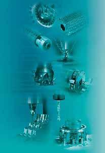
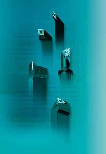
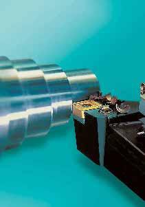
7 6 Spezialisten und ihre Stärken 6 specialists and their strengths Belin, Frankreich, ist ein Technologieführer für Hochleistungs-Reibahlen aus Hartmetall, PKD und CBN sowie für hochgenaue Nutenfräser und Vollhartmetall- Schaftfräser für Kunststoffe und Aluminiumlegierungen. Belin (France) is a technological leader for high-performance carbide metal reamers, PKD and CBN and high-precision grooving mills and all-carbide end milling cutters for plastics and aluminium alloys. Bilz, Deutschland, ist auf dem Gebiet der Werkzeugspanntechnik tätig und heute der führende Hersteller von Gewindeschneidfuttern und des Thermo-Grip - Systems für das thermische Spannen von rotierenden Werkzeugen. Bilz (Germany) operates in the field of tool clamping and is now the leading manufacturer of thread-tapping chucks and also of the Thermo-Grip system for the thermal clamping of revolving tools. Boehlerit, Österreich, steht als Hersteller von Schneidstoffen für die Metall-, Verbundwerkstoff-, Kunststoff- und Holzbearbeitung sowie von Hartmetallen für nicht spanende Anwendungen weltweit für höchste Fertigungsperfektion von Hartmetallen und Werkzeugen zum Drehen, Fräsen, Bohren und Drehschälen sowie für die spanlose Formgebung. Boehlerit (Austria), a manufacturer of cutting materials for metal, composites, plastics and wood and of carbide metals for non-cutting applications, has a high worldwide reputation for ultimate precision in the processing of carbide metals and tools for lathe turning, milling, drilling and rotary peeling, and also for chipless forming. Fette, Deutschland, nimmt als Hersteller von Präzisions-Fräswerkzeugen und Wälzfräsern mit einem breiten Programm aus Hartmetall und Schnellstahl für die Metall- und Kunststoffbearbeitung sowie für Gewinderollsysteme und Gewindebohrer eine herausragende Stellung ein. Fette (Germany) has earned an outstanding position as a manufacturer of precision milling and hobbing tools and supplies an extensive programme of carbide-metal and high-speed steel tools for metal and plastics processing and for thread rolling systems and thread tapping dies. Kieninger, Deutschland, ist auf dem Gebiet der Sonderzerspansysteme für komplexe Bohrungsbearbeitung und der Präzisionsbearbeitung im Gesenk- und Formenbau sowie für den Werkzeug- und Modellbau in weltweit anerkannter Spitzenstellung. Kieninger (Germany) occupies a leading position on the market for special cutting systems used for more complex bore machining and precision machining work within the dies and moulds industries and for the machining of engine components for the automotive industry. Onsrud, USA, ist spezialisiert auf die Herstellung von Schaftfräsern für die Hochgeschwindigkeitsbearbeitung von Aluminium, Kunststoffen und Verbundwerkstoffen in der Luft- und Raumfahrtindustrie. Onsrud (USA) specialises in the production of end-milling cutters for high-speed machining of aluminium, plastics and composite materials in the aerospace industries. 5
8 6
9 Kompetenzen und Referenzen der LMT LMT s competences and references Das Produktangebot der sechs LMT-Unternehmen umfasst mehr als Werkzeuge aus eigener Entwicklung und Herstellung. Hinter dieser Vielfalt steht ein außerordentliches Wissens- und Erfahrungspotenzial. Seit der ersten Stunde maschineller Metallbearbeitung sind Unternehmen der LMT an der Entwicklung effizienter Maschinen-Werkzeuge, an ihrer Weiterentwicklung und Ausrichtung auf neue Werkstoffe, immer neue Spitzenleistungen in Präzision, Qualität, Zeitund Kostenersparnis maßgeblich beteiligt. Die LMT-Unternehmen bieten Werkzeugsysteme und Zubehör für die gesamte Bandbreite moderner Zerspanungstechnik. Sie können ihren Kunden deshalb eine objektiv systemneutrale Beratung und Empfehlung garantieren, welche Bearbeitungsabläufe sich mit welchen Verfahren und welcher Werkzeugbestückung am besten und wirtschaftlichsten lösen lassen. Dazu beherrscht die LMT alle Schneidstoffe und zugleich auch die modernsten Beschichtungsverfahren. Mehr und mehr Kunden nehmen diese Beratungskompetenz für sich in Anspruch mit eindeutig überzeugenden Vorteilen. Wenn sich innerhalb der breiten Palette an Standardwerkzeugen keine Lösung für Ihren Anwendungsfall finden lässt, dann geht die LMT zusammen mit Ihnen den Weg, durch Entwicklungen und Versuche das für Sie optimale Sonderwerkzeug zu produzieren. Gerne zeigen wir Ihnen unsere Leistungsstärke anhand ausführlicher Referenzen aus der langjährigen Zusammenarbeit mit der Automobil- und Zulieferindustrie, dem Nutzfahrzeugbau, der Luft- und Raumfahrt, wie dem allgemeinen Maschinenbau. Auch die modernen Felder der Zerspantechnik in Medizin, Optik, Elektronik oder Windkraft sind maßgeblich durch Werkzeuge der LMT geprägt. The product programme available from the six LMT companies comprises more than 30,000 tools, developed and manufactured by the companies themselves. This sheer variety is backed by exceptional knowledge and experience. Ever since machine metalworking methods first appeared, LMT companies have been closely involved in the design and ongoing development of efficient machine tools, including adapting them to process new materials and achieve constantly new peak performance levels in terms of precision, quality, speed and economy. LMT companies supply tool systems and accessories for every area of modern cutting technology. This enables them to offer their clients objective advice and recommendations not restricted to specific systems and to make specific proposals for the most suitable processes and tools to be used for the best results and maximum economy. LMT has total mastery of all cutting materials and also of the latest coating processes. More and more clients make use of LMT s advisory skills with convincing benefits all round. If it is not possible to find a solution for your task within the big range of standard tools, LMT makes its full development and experimental resources available to you so that the ideal special tool can be produced. LMT companies will gladly supply detailed references from their long-standing cooperation with the automobile and component supply industries, manufacturers of rail, off-road and waterborne vehicles, aerospace and general machinery construction areas. Many of the most advanced cutting processes used in medicine, optics, electronics or wind-power generation have been greatly promoted by the use of LMT tools. 7
10 8
11 Inhaltsübersicht Contents Wichtige Bestell- und Lieferhinweise Important hints for ordering and delivery 10 Drehen Programmübersicht Spanformstufengeometrien ISO-Bezeichnungssysteme Wendeschneidplatten Klemmhalter Technische Hinweise Turning 13 Range of Tools 14 Chip groove geometries 23 ISO-Designation systems 28 Indexable inserts 34 Tool holders 58 Technical hints 92 Dreh-Bohr-Werkzeug Pentatec Fünf Bearbeitungsoperationen, ein Werkzeug Schnittparameter Halterprogramm Wendeschneidplatten Bezeichnungssystem Technische Hinweise Turning-Drilling-Tool Pentatec 127 Five machining operations, one tool 128 Cutting parameters 129 Tool holders 130 Indexable inserts 130 Designation system 131 Technical hints 132 Stechen, Stechdrehen mit EasyTec Systemvorteile Programmübersicht Spanformstufengeometrien Bezeichnungssysteme Wendeschneidplatten Spannblock, Klingen Klemmhalter Technische Hinweise Gewindedrehen Wendeschneidplatten Klemmhalter Technische Hinweise Grooving and Groove-turning with Easy Tec 137 Advantages of the system 138 Program range 140 Chip groove geometries 142 Designation systems 146 Indexable inserts 152 Parting holder, blades 166 Tool holders 168 Technical hints 178 Thread Turning 197 Indexable inserts 198 Tool holders 220 Technical hints 222 Schälköpfe Wendeplatten Schälköpfe Einstelllehren Anfaser Technische Hinweise Turning heads 229 Indexable inserts 230 Turning heads 232 Setting gauges 234 Chamfering tools 235 Technical hints 237 Drehschälen Bar Peeling 241 Anhang Werkstückstoff-Vergleichstabelle Vergleich ISO- zu ANSI-Kennzeichnung Härte Vergleichstabelle Attachment 243 Comparison of material standards 244 Comparison ISO- and ANSI-designation 252 Hardness comparison table 256 9
12 Wichtige Bestellhinweise Important Hints Programmaktualität Das LMT-Gesamtprogramm in verschiedenen Katalogen mit ca Standardartikeln unterliegt einer ständigen Programmpflege. Im Rahmen dieser kontinuierlichen Aktualisierung nehmen wir nicht nur neue und damit technisch bessere Produkte im Programm auf, sondern führen auch eine intensive Programmbereinigung durch. Es kann also im Einzelfall passieren, dass wir einen von Ihnen bestellten Artikel nicht mehr lagermäßig führen. Sie erhalten dann von uns in der Regel ein technologisch besseres Produkt, mindestens aber eine gleichwertige Alternative. In Zweifelsfällen werden sich unsere Verkaufsteams mit Ihnen in Verbindung setzen, um eine für Sie optimale Ausführung zu bestimmen. Dadurch ist sichergestellt, dass Sie stets mit Werkzeugen beliefert werden, die auf dem neuesten Stand der Technik sind. Eine Verpflichtung zur Lieferung von im Katalog abgebildeten Werkzeugen, die aber bereits ersetzt wurden, übernehmen wir nicht. Artikelnummern Um die Auftragsbearbeitung zu beschleunigen und Verwechslungen auszuschließen, bitten wir bei Aufträgen um Angabe der im Katalog genannten Artikelnummern und/oder der Artikelbezeichnung. Preise Dieser Katalog enthält keine Preise. Diese entnehmen Sie bitte der jeweils gültigen Preisliste. Mindestauftragswert Wir bitten um Verständnis, dass wir Aufträge bis zu einem Gesamtwert von 100, nur gegen eine zusätzliche Bearbeitungsgebühr in Höhe von 30, ausführen können. Werkzeuggruppen Unser breites Programm an Präzisionswerkzeugen ist nach Werkzeuggruppen geordnet, die durch ein Register an der Seite des Kataloges kenntlich gemacht und dadurch leicht aufzufinden sind. Werkzeugauswahl Am Anfang jeder Werkzeuggruppe stehen Auswahlübersichten, die Ihnen ein schnelles Auffinden der Werkzeuge für Ihren Anwendungsfall ermöglichen. Anwendungstechnische Hinweise Ab Seite 244 finden Sie technische Hinweise von allgemeiner, übergeordneter Gültigkeit. Dagegen sind die speziellen technischen Hinweise zu den einzelnen Produktgruppen dem jeweiligen Abschnitt direkt zugeordnet. Werkzeuge Wenn nicht anders angegeben, sind die Werkzeuge rechtsschneidend bzw. für Rechtsgewinde. Z=Zähnezahl = Anzahl der Schneiden = Anzahl der Spannuten = Anzahl der Zahnreihen Sonderformen Sollten Sie eines Ihrer Bearbeitungsprobleme nicht mit einem unserer ca lagergängigen Werkzeuge lösen können, bieten wir Ihnen Sonderformen oder zeichnungsgebundene Werkzeuge auf Anfrage an. Unsere Anwendungstechniker beraten Sie gern. Programme updating The LMT catalogue programme covers approx standard items this under constant review. Within the framework of a continuous bringing cleaning, we not only adapt new and therefore technologically better products into the programme, but we also engage in intensive programme clearing. In some cases it could happen that we do not carry in stock the item which you have ordered. In that case you will in general receive a technologically better product which is at least an equivalent alternative. In case of doubt, our sales teams will contact you, in order to determine a design that will produce best possible results for you. By this, it is sure that you are always supplied with tools, which are technologically on the newest level. For that reason, we do not feel obliged to supply tools, shown in the catalogue, which have been cleared or superceded from the programme profile. Article numbers To speed up order processing and to avoid confusions, orders should always specify the ident numbers and/or item designation listed in the catalogue. Prices For prices, please refer to the current price list. Minimum order value A handling fee of 30, is charged for orders up to a total value of 100,. Tool groups Our wide range of precision tools is subdivided into tool groups. These are identified by an index in the catalogue so that they can be located quickly. Tool selection A broad table of selection is shown in front of each tool section, this makes it possible for you to pick out requirements quickly which are suitable for your application. Technical details Technical application details commence on page 244, the technical details concerning individual product groups are directly assigned to the section concerned. Tools If not specified otherwise, tools are for right-hand or for a righthand thread. Z = Number of teeth = Number of cutting edges = Number of flutes = Number of tooth rows Special designs If you find that your specific machining problems cannot be resolved with any of our permanently stocked tools, then we can supply special designs or tools made according to drawings. Our application technicians will be glad to help you. 10

13 Das LMT-Farbleitsystem LMT Colour Identification System Steigern Sie Ihre Effizienz mit colorguide, dem perfekten Farbleitsystem zur Auswahl der richtigen Wendeschneidplatte. Dieser Wegweiser durch die Vielfalt, den Sie auf dem Etikett jeder LMT-Wendeschneidplattenschachtel finden, gibt Ihnen rasch und verlässlich Auskunft über die Eignung einer bestimmten Wendeplatte für den jeweiligen Bearbeitungsfall. Colorguide spart Zeit und hilft Fehlanwendungen zu vermeiden. Increase your efficiency with colorguide, the perfect colour identification system for finding the right indexable insert. This guide through the variety which you will find on the label of each LMT indexable inserts box informs you quickly and reliably about the suitability of this indexable insert for the intended machining operation. Colorguide saves time and helps to avoid wrong applications. In einem Raster, der senkrecht in sechs mit Farben gekennzeichnete Materialhauptgruppen (nach VDI 3323) und waagrecht in drei Bearbeitungsstufen (von grob ROUGH über mittel MEDIUM nach fein FINE) geteilt ist, geben die aufgedruckten Symbole Auskunft über den oder die Anwendungsbereiche einer bestimmten Wendeplatte. Am oben gezeigten Beispiel: DNMG BFM in der Sorte LC225C ist hauptsächlich für die mittlere Bearbeitung von Stahl und daneben auch für die mittlere Bearbeitung von nichtrostendem Stahl im kontinuierlichen Schnitt geeignet. Symbols printed in a grid which is vertically organized into six main material groups represented by colours (acc. to VDI 3323) and horizontally by three levels of machining (ROUGH - MEDIUM - FINE) define the field(s) of application of the indexable insert. For example, the above label tells you: DNMG BFM in grade LC225C is primarily suitable for medium turning of steels but also for turning of stainless steels, both in continuous cut. In die Materialhauptgruppen fallen die nachstehend angeführten Werkstoffgruppen: Stahl: Automaten-, Einsatz-, Vergütungs- und Baustähle, weißer Temperguss Nichtrostender Stahl: Ferritische Cr-Stähle, martensitische CrNi-Stähle, austenitische CrNi-Stähle Eisenguss: Grauguss, Temperguss, Sphäroguss, Sintereisen Nichteisen-Metalle: Al-Knet- und Al-Gusslegierungen, auch Weichkunststoffe, faserverstärkte Kunststoffe Hochwarmfeste Legierungen: Hitzebeständige Stähle, Ni-/Co-Basis-Legierungen, Ti-Legierungen Gehärtete Werkstoffe: Gehärtete Stähle (45 HRC), Einsatzstähle, Schalenhartguss The main material groups include the following materials: Steel: Free cutting steels, case hardening steels, heat treatment steels, constructional steels, white malleable cast iron Stainless steels: Ferritic Cr-steels, martensitic CrNi-steels, austenitic CrNi-steels Cast iron: Grey cast iron, malleable cast iron, spheroidal cast iron, sintered iron Non-ferrous metal: Al wrought and Al cast alloys, also soft plastics and fiber-reinforced plastics High-temperature alloys: Heat resistant steels, alloys on Ni/Co basis, Ti alloys Hardened materials: Hardened steels ( 45 HRC), case hardened steels, clear chill castings. Werkstoffgruppen Material groups Stahl Steel Nichtrostender Stahl Stainless steel Eisenguss Iron casting Nichteisen-Metalle Non-ferrous metals Hochwarmfeste Legierungen High temperature alloys Gehärtete Werkstoffe Hardened materials Bearbeitungsarten Machining mode Vorschub f (mm) Feed f (mm) Schnitttiefe a p (mm) Depth of cut a p (mm) Anwendungsbereiche Application area Hauptanwendung Main application Nebenanwendung Other application Rough Medium Fine Rough Medium Fine 0,6 1,2 0,25 0,6 0,05 0, ,5 5 0,1 1,5 kontinuierlicher Schnitt Continuous cut unterbrochener Schnitt Interrupted cut 11
14 12
15 Drehen Turning Programmübersicht Range of tools Klemmhalter und Wendeschneidplatten für die Außenbearbeitung 14 Tool holders and indexable inserts for external machining Klemmhalter und Wendeschneidplatten für die Innenbearbeitung 20 Tool holders and indexable inserts for internal machining Spanformstufengeometrien Chip groove geometries für Stähle, rostfreie Stähle, Nichteisenmetalle 23 for steel, stainless steel, non-ferrous metals ISO-Bezeichnungssyteme ISO-designation systems für Wendeschneidplatten 28 for indexable inserts für Klemmhalter für die Außenbearbeitung 30 for tool holders, external machining für Klemmhalter für die Innenbearbeitung 32 for tool holders, internal machining Wendeschneidplatten 34 Indexable inserts Klemmhalter 58 Tool holders Technische Hinweise Technical hints Klemmhalter-Spannsysteme 92 Tool holder clamping systems Wahl des Spannsystemes 93 Selecting a clamping system Wahl der Werkzeuge für die Innenbearbeitung 94 Selecting tools for internal machining Wahl der Wendeplattengröße 95 Selecting the indexable insert size Wahl der Wendeplattenform 96 Selecting the indexable insert shape Schlichtbearbeitung 98 Finishing Formeln für die Drehbearbeitung 100 Formulas for machining work Maßnahmen bei Drehproblemen 101 Options against machinig problems LMT-Schneidstoffsorten, Bezeichnung 102 LMT-Grade designation LMT-Drehsorten, Übersicht 103 LMT-Turning grades, overview LMT-Drehsorten, Einsatzbereiche 104 LMT-Turning grades, ranges of application Schnittdatenrichtwerte, Drehen 106 Cutting data standard values 13
16 Programmübersicht Range Werkzeuge und Wendeplatten für die Außenbearbeitung Tool holders and indexable inserts for external machining Schnittrichtung Anstellwinkel Werkzeug Bestellbezeichnung Seiten Cutting direction Setting angle Tool Ordering Code Pages 75 Klemmhalter Tool holder PCBNR/L 58 Wendeplatte Indexable inserts CNMA 35 CNMG CNMM 37 CNMX Klemmhalter Tool holder PCKNR/L 58 Wendeplatte Indexable inserts CNMA 35 CNMG CNMM 37 CNMX Klemmhalter Tool holder PCLNR/L 58 Wendeplatte Indexable inserts CNGA 35 CNMA 35 CNMG CNMM 37 CNMX Klemmhalter Tool holder PDJNR/L 59 Wendeplatte Indexable inserts DNGA 39 DNMA 39 DNMG DNMM Klemmhalter Tool holder PDJNR/L Wendeplatte Indexable inserts DNMG Klemmhalter Tool holder PDNNR/L 59 Wendeplatte Indexable inserts DNGA 39 DNMA 39 DNMG DNMM 41 Klemmhalter Tool holder PRDCN 60 Wendeplatte Indexable inserts RCMX Klemmhalter Tool holder PRGCR/L 60 Wendeplatte Indexable inserts RCMX Klemmhalter Tool holder PSBNR/L 61 Wendeplatte Indexable inserts SNGA 46 SNMA 46 SNMG SNMM 47 SNMX 47 14
17 Schnittrichtung Anstellwinkel Werkzeug Bestellbezeichnung Seiten Cutting direction Setting angle Tool Ordering Code Pages 45 Klemmhalter Tool holder PSDNN 61 Wendeplatte Indexable inserts SNGA 46 SNMA 46 SNMG SNMM 47 SNMX Klemmhalter Tool holder PSKNR/L 61 Wendeplatte Indexable inserts SNGA SNMA SNMG SNMM SNMX Klemmhalter Tool holder PSSNR/L 62 Wendeplatte Indexable inserts SNGA SNMA SNMG SNMM SNMX Klemmhalter Tool holder PTFNR/L 63 Wendeplatte Indexable inserts TNMA TNMG TNMM TNMX Klemmhalter Tool holder PTGNR/L 63 Wendeplatte Indexable inserts TNMA TNMG TNMM TNMX Klemmhalter Tool holder PTTNR/L 63 Wendeplatte Indexable inserts TNMA TNMG TNMM TNMX Klemmhalter Tool holder PWLNR/L 64 Wendeplatte Indexable inserts WNMG Klemmhalter Tool holder MSSNR/L 65 Wendeplatte Indexable inserts SNMA SNMG SNMM SNMX Klemmhalter Tool holder MTJNR/L 65 Wendeplatte Indexable inserts TNMA TNMG TNMM TNMX
18 Programmübersicht Range Werkzeuge und Wendeplatten für die Außenbearbeitung Tool holders and indexable inserts for external machining Schnittrichtung Anstellwinkel Werkzeug Bestellbezeichnung Seiten Cutting direction Setting angle Tool Ordering Code Pages 95 Klemmhalter Tool holder MWLNR/L 66 Wendeplatte Indexable inserts WNMG Klemmhalter Tool holder SCACR/L 67 Wendeplatte Indexable inserts CCGT CCGW CCMT CCMW Klemmhalter Tool holder SCDCL 67 Wendeplatte Indexable inserts CCGT CCGW CCMT CCMW Klemmhalter Tool holder SCFCR/L 67 Wendeplatte Indexable inserts CCGT CCGW CCMT CCMW Klemmhalter Tool holder SCGCR/L 68 Wendeplatte Indexable inserts CCGT CCGW CCMT CCMW Klemmhalter Tool holder SCLCR/L 68 Wendeplatte Indexable inserts CCGT CCGW CCMT CCMW Klemmhalter Tool holder SCMCN 68 Wendeplatte Indexable inserts CCGT CCGW CCMT CCMW Klemmhalter Tool holder SCRCR/L 69 Wendeplatte Indexable inserts CCGT CCGW CCMT CCMW Klemmhalter Tool holder SCSCR/L 69 Wendeplatte Indexable inserts CCGT CCGW CCMT CCMW
19 Schnittrichtung Anstellwinkel Werkzeug Bestellbezeichnung Seiten Cutting direction Setting angle Tool Ordering Code Pages 90 Klemmhalter Tool holder SDACR/L 70 Wendeplatte Indexable inserts DCGT DCGW DCMT DCMW ,5 Klemmhalter Tool holder SDHCR/L 70 Wendeplatte Indexable inserts DCGT DCGW DCMT DCMW Klemmhalter Tool holder SDJCR/L 70 Wendeplatte Indexable inserts DCGT DCGW DCMT DCMW ,5 Klemmhalter Tool holder SDNCN 71 Wendeplatte Indexable inserts DCGT DCGW DCMT DCMW Klemmhalter Tool holder SRDCN 72 Wendeplatte Indexable inserts RCGT RCMT Klemmhalter Tool holder SRGCR/L 72 Wendeplatte Indexable inserts RCGT RCMT Klemmhalter Tool holder SSBCR/L 73 Wendeplatte Indexable inserts SCGT SCGW SCMT SCMW Klemmhalter Tool holder SSDCN 73 Wendeplatte Indexable inserts SCGT SCGW SCMT SCMW Klemmhalter Tool holder SSKCR/L 73 Wendeplatte Indexable inserts SCGT SCGW SCMT SCMW
20 Programmübersicht Range Werkzeuge und Wendeplatten für die Außenbearbeitung Tool holders and indexable inserts for external machining Schnittrichtung Anstellwinkel Werkzeug Bestellbezeichnung Seiten Cutting direction Setting angle Tool Ordering Code Pages 45 Klemmhalter Tool holder SSSCR/L 74 Wendeplatte Indexable inserts SCGT SCGW SCMT SCMW Klemmhalter Tool holder STACR/L 75 Wendeplatte Indexable inserts TCGT TCGW TCMT TCMW Klemmhalter Tool holder STCCN 75 Wendeplatte Indexable inserts TCGT TCGW TCMT TCMW Klemmhalter Tool holder STCFCR/L 75 Wendeplatte Indexable inserts TCGT TCGW TCMT TCMW Klemmhalter Tool holder STGCR/L 76 Wendeplatte Indexable inserts TCGT TCGW TCMT TCMW ,5 Klemmhalter Tool holder SVHBR/L 77 Wendeplatte Indexable inserts VBMT ,5 Klemmhalter Tool holder SVHCR/L 77 Wendeplatte Indexable inserts VCGT VCMT Klemmhalter Tool holder SVJBR/L 78 Wendeplatte Indexable inserts VBMT Klemmhalter Tool holder SVJCR/L 78 Wendeplatte Indexable inserts VCGT VCMT
21 Schnittrichtung Anstellwinkel Werkzeug Bestellbezeichnung Seiten Cutting direction Setting angle Tool Ordering Code Pages 93 Klemmhalter Tool holder SVJOR/L 78 Wendeplatte Indexable inserts VOGT VOGW ,5 Klemmhalter Tool holder SVVBN 79 Wendeplatte Indexable inserts VBMT ,5 Klemmhalter Tool holder SVVON 79 Wendeplatte Indexable inserts VOGT VOGW ,5 Klemmhalter Tool holder SVVCN 79 Wendeplatte Indexable inserts VCGT VCMT Klemmhalter Tool holder SVZCR/L 79 Wendeplatte Indexable inserts VCGT VCMT Klemmhalter Tool holder SWLCR/L 80 Wendeplatte Indexable inserts WCGT WCMT
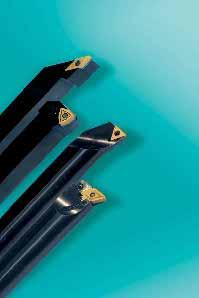
22 Programmübersicht Range Werkzeuge und Wendeplatten für die Innenbearbeitung Tool holders and indexable inserts for internal machining Schnittrichtung Anstellwinkel Werkzeug Bestellbezeichnung Seiten Cutting direction Setting angle Tool Ordering Code Pages 95 Klemmhalter Tool holder PCLNR/L 81 Wendeplatte Indexable inserts CNGA 35 CNMA 35 CNMG CNMM 37 CNMX Klemmhalter Tool holder PDUNR/L 82 Wendeplatte Indexable inserts DNGA 39 DNMA 39 DNMG DNMM Klemmhalter Tool holder PDUNR/L Wendeplatte Indexable inserts DNMG Klemmhalter Tool holder PSKNR/L 83 Wendeplatte Indexable inserts SNGA 46 SNMA 46 SNMG SNMM 47 SNMX Klemmhalter Tool holder PTFNR/L 83 Wendeplatte Indexable inserts TNMA 50 TNMG TNMM 51 TNMX Klemmhalter Tool holder PWLNR/L 84 Wendeplatte Indexable inserts WNMG Klemmhalter Tool holder 29629/ Wendeplatte Indexable inserts CNGA 35 CNMA 35 CNMG CNMM 37 CNMX Klemmhalter Tool holder MWLNR/L 85 Wendeplatte Indexable inserts WNMG 06T Klemmhalter Tool holder SCFCR/L 86 Wendeplatte Indexable inserts CCGT CCGW CCMT CCMW
23 Schnittrichtung Anstellwinkel Werkzeug Bestellbezeichnung Seiten Cutting direction Setting angle Tool Ordering Code Pages 95 Klemmhalter Tool holder SCLCR/L 86 Wendeplatte Indexable inserts CCGT CCGW CCMT CCMW ,5 Klemmhalter Tool holder SDQCR/L 87 Wendeplatte Indexable inserts DCGT DCGW DCMT DCMW Klemmhalter Tool holder SDUCR/L 87 Wendeplatte Indexable inserts DCGT DCGW DCMT DCMW Klemmhalter Tool holder STFCR/L 88 Wendeplatte Indexable inserts TCGT TCGW TCMT TCMW ,5 Klemmhalter Tool holder SVQCR/L 89 Wendeplatte Indexable inserts VCGT VCMT Klemmhalter Tool holder SVUBR/L 89 Wendeplatte Indexable inserts VBMT Klemmhalter Tool holder SVUCR/L 89 Wendeplatte Indexable inserts VCGT VCMT Klemmhalter Tool holder SVUOR/L 90 Wendeplatte Indexable inserts VOGT VOGW Klemmhalter Tool holder SWLCR/L 90 Wendeplatte Indexable inserts WCGT WCMT
24 Programmübersicht Range Werkzeuge und Wendeplatten für die Innenbearbeitung Tool holders and indexable inserts for internal machining Schnittrichtung Anstellwinkel Werkzeug Bestellbezeichnung Seiten Cutting direction Setting angle Tool Ordering Code Pages 75 Klemmhalter Tool holder S73P 91 Wendeplatte Indexable inserts SPMR SPUN TPMR Klemmhalter Tool holder S74P 91 Wendeplatte Indexable inserts TPMR TPUN
25 Spanformstufengeometrien für Stähle Chip groove geometries for steel Hauptgeometrien Main geometries Schnittiefe a p Depth of out a p (mm) 16 12, , ,2 2,5 2 1,6 1,2 1 0,8 0,63 0,5 0,4 0,32 0,25 0,2 0,16 0,12 0,1 E A BF BR BM C B 0,025 0,04 0,063 0,1 0,16 0,25 0,4 0,63 1,0 1,6 2,5 0,032 0,05 0,08 0,12 0,2 0,32 0,5 0,8 1,2 2,0 Vorschub f Feed f (mm) D F Für negative Wendeschneidplatten passend für die ISO P- u. M-Spannsysteme For negative indexable inserts suitable for ISO P and M clamping systems Kontrollierte Spanbildung über den gesamten Anwendungsbereich von der Feinstbearbeitung bis zur groben Schruppbearbeitung. Controlled chip forming over the whole range of application from roughing to finishing. Schruppgeometrie BR (Boehlerit Roughing) BR roughing geometry (Boehlerit Roughing) Universelle Geometrie BM (Boehlerit Medium) Universal BM geometry (Boehlerit Medium) Schlichtgeometrie BF (Boehlerit Finishing) BF finishing geometry (Boehlerit Finishing) Zwischengeometrien Intermediate geometries Schnittiefe a p Depth of out a p (mm) 16 12, , ,2 2,5 2 1,6 1,2 1 0,8 0,63 0,5 0,4 0,32 0,25 0,2 0,16 0,12 0,1 E A BMR BFM D C F 0,025 0,04 0,063 0,1 0,16 0,25 0,4 0,63 1,0 1,6 2,5 0,032 0,05 0,08 0,12 0,2 0,32 0,5 0,8 1,2 2,0 B Vorschub f Feed f (mm) Für negative Wendeschneidplatten passend für die ISO P- u. M-Spannsysteme For negative indexable inserts suitable for ISO P and M clamping systems Grobe Übergangsgeometrie BMR (Boehlerit Medium/Roughing) Vorzugsweise für Gußwerkstoffe BMR rough intermediate geometry (Boehlerit Medium/Roughing) Preferably for cast materials Feine Übergangsgeometrie BFM (Boehlerit Finishing/Medium) Vorzugsweise für rostfreie Stähle BFM fine intermediate geometry (Boehlerit Finishing/Medium) Preferably for stainless steels 23
26 Spanformstufengeometrien für Stähle Chip groove geometries for steel Geometrie zum Kopierdrehen Geometry for copy turning Schnittiefe a p Depth of out a p (mm) 16 12, , ,2 2,5 2 1,6 1,2 1 0,8 0,63 0,5 0,4 0,32 0,25 0,2 0,16 0,12 0,1 E A BC B D C F 0,025 0,04 0,063 0,1 0,16 0,25 0,4 0,63 1,0 1,6 2,5 0,032 0,05 0,08 0,12 0,2 0,32 0,5 0,8 1,2 2,0 Für negative Wendeschneidplatten passend für das ISO P-Spannsystem For negative indexable inserts suitable for ISO P clamping system Vorschub f Feed f (mm) Geometrie zum Kopierdrehen BC (Boehlerit Copying) Geometry BC (Boehlerit Copying) Hauptgeometrien Main geometries Schnittiefe a p Depth of out a p (mm) 16 12, , ,2 2,5 2 1,6 1,2 1 0,8 0,63 0,5 0,4 0,32 0,25 0,2 0,16 0,12 0,1 E A BSM BSF D C F 0,025 0,04 0,063 0,1 0,16 0,25 0,4 0,63 1,0 1,6 2,5 0,032 0,05 0,08 0,12 0,2 0,32 0,5 0,8 1,2 2,0 B Vorschub f Feed f (mm) Für positive Wendeschneidplatten passend für das ISO S-Spannsystem For positive indexable inserts suitable for ISO S clamping system Universelle Geometrie BSM (Boehlerit S-ISO System Medium) Universal BSM geometry (Boehlerit ISO S system Medium) Schlicht-Geometrie BSF (Boehlerit S-ISO System Finishing) BSF finishing geometry (Boehlerit ISO S system Finishing) 24
27 Spanformstufengeometrien für rostfreie Stähle Chip groove geometries for stainless steel Hauptgeometrien Main geometries Schnittiefe a p Depth of out a p (mm) 16 12, , ,2 2,5 2 1,6 1,2 1 0,8 0,63 0,5 0,4 0,32 0,25 0,2 0,16 0,12 0,1 E A BMS BFMS D BMRS C B F 0,025 0,04 0,063 0,1 0,16 0,25 0,4 0,63 1,0 1,6 2,5 0,032 0,05 0,08 0,12 0,2 0,32 0,5 0,8 1,2 2,0 Vorschub f Feed f (mm) Für negative Wendeschneidplatten passend für die ISO P- u. M-Spannsysteme For negative indexable inserts suitable for ISO P and M clamping systems Kontrollierte Spanbildung ohne Kaltverfestigung über den gesamten Anwendungsbereich von der Feinbearbeitung bis zur Grobbearbeitung von austenitischen rostbeständigen Stählen. Controlled chip forming without cold hardening over the whole range of application from roughing to finishing of austenitic steels. Grobe Geometrie BMRS (Boehlerit Medium/Roughing Stainless steel) Roughing Geometry BMRS (Boehlerit Medium/Roughing Stainless steel) Universelle Geometrie BMS (Boehlerit Medium Stainless steel) Universal Geometry BMS (Boehlerit Medium Stainless steel) Feine Geometrie BFMS (Boehlerit Finishing/Medium Stainless steel) Finishing Geometry BFMS (Boehlerit Finishing/Medium Stainless steel) Schnittiefe a p Depth of out a p (mm) 16 12, , ,2 2,5 2 1,6 1,2 1 0,8 0,63 0,5 0,4 0,32 0,25 0,2 0,16 0,12 0,1 E A BSMS D C B F 0,025 0,04 0,063 0,1 0,16 0,25 0,4 0,63 1,0 1,6 2,5 0,032 0,05 0,08 0,12 0,2 0,32 0,5 0,8 1,2 2,0 Vorschub f Feed f (mm) Hauptgeometrie Main geometry Für positive Wendeschneidplatten passend für das ISO S-Spannsystem For positive indexable inserts suitable for the ISO-S clamping system Universelle Geometrie BSMS (Boehlerit ISO-S Medium Stainless Steel) Universal Geometry BSMS (Boehlerit ISO-S Medium Stainless Steel) 25
28 Spanformstufengeometrien für Stähle Chip groove geometries for steel Schnittiefe a p Depth of out a p (mm) 16 12, , ,2 2,5 2 1,6 1,2 1 0,8 0,63 0,5 0,4 0,32 0,25 0,2 0,16 0,12 0,1 E A TF NF SF B D C F 0,025 0,04 0,063 0,1 0,16 0,25 0,4 0,63 1,0 1,6 2,5 0,032 0,05 0,08 0,12 0,2 0,32 0,5 0,8 1,2 2,0 Vorschub f Feed f (mm) Geometrien für negative Cermet-Wendeplatten Geometries for Cermet negative indexable inserts Für negative Wendeschneidplatten passend für die ISO P- u. M-Spannsysteme For negative indexable inserts suitable for ISO P and M clamping systems Geometrie TF Geometry TF Geometrie NF Geometry NF Geometrie SF Geometry SF Schnittiefe a p Depth of out a p (mm) 16 12, , ,2 2,5 2 1,6 1,2 1 0,8 0,63 0,5 0,4 0,32 0,25 0,2 0,16 0,12 0,1 E A WG D C B F 0,025 0,04 0,063 0,1 0,16 0,25 0,4 0,63 1,0 1,6 2,5 0,032 0,05 0,08 0,12 0,2 0,32 0,5 0,8 1,2 2,0 Wiper-Geometrie für negative Cermet-Wendeplatten Wiper-geometry for Cermet negative indexable inserts Vorschub f Feed f (mm) Geometrie WG Geometry WG 26
29 Spanformstufengeometrien für Stähle Chip groove geometries for steel Schnittiefe a p Depth of out a p (mm) 16 12, , ,2 2,5 2 1,6 1,2 1 0,8 0,63 0,5 0,4 0,32 0,25 0,2 0,16 0,12 0,1 E A CF D C B F 0,025 0,04 0,063 0,1 0,16 0,25 0,4 0,63 1,0 1,6 2,5 0,032 0,05 0,08 0,12 0,2 0,32 0,5 0,8 1,2 2,0 Vorschub f Feed f (mm) Geometrie für positive Cermet-Wendeplatten Geometry for Cermet positive indexable inserts Für positive Wendeschneidplatten passend für das ISO S-Spannsystem For positive indexable inserts suitable for the ISO-S clamping system Geometrie CF Geometry CF Spanformstufengeometrien für Nichteisenmetalle Chip groove geometry for non-ferrous metals Hauptgeometrie für Alu Geometry for aluminium machining Schnittiefe a p Depth of out a p (mm) 16 12, , ,2 2,5 2 1,6 1,2 1 0,8 0,63 0,5 0,4 0,32 0,25 0,2 0,16 0,12 0,1 E A BAL D C F 0,025 0,04 0,063 0,1 0,16 0,25 0,4 0,63 1,0 1,6 2,5 0,032 0,05 0,08 0,12 0,2 0,32 0,5 0,8 1,2 2,0 B Vorschub f Feed f (mm) Für positive Wendeschneidplatten passend für das ISO S-Spannsystem For positive indexable inserts suitable for ISO S clamping system Auch hervorragend zum SCHLICHTEN von rostfreien Stählen geeignet. Best suitable for finishing of stainless steels also. Geometrie für Aluminium BAL (Boehlerit-ALuminium) Geometry BAL (Boehlerit ALuminium) 27
30 ISO-Bezeichnungssytem ISO designation system für Wendeschneidplatten for indexable inserts W Grundform Basic form N Freiwinkel Clearence angle M Toleranzklasse Tolerance classes G Plattentype Type of insert A 85 B 82 C 80 D 55 E 75 H 120 K 55 L 90 A B C D E F Zulässige Abweichung für Limits of tolerance m s d A ±0,005 3) ±0,025 ±0,025 C ±0,013 ±0,025 ±0,025 E ±0,025 ±0,025 ±0,025 F ±0,005 3) ±0,025 ±0,013 G ±0,025 ±0,13 ±0,025 H ±0,013 ±0,025 ±0,013 J ±0,005 3) ±0,025 ±0,05 ±0,15 K ±0,013 3) ±0,025 ±0,05 ±0,15 L ±0,025 ±0,025 ±0,05 ±0,15 M ±0,08 ±0,20 ±0,13 ±0,05 ±0,15 U ±0,13 ±0,38 ±0,13 ±0,08 ±0,25 d m d M 6,35 ±0,08 ±0,05 9,52 ±0,08 ±0,05 12,7 ±0,13 ±0,08 15,88 ±0,15 ±0,10 19,05 ±0,15 ±0,10 25,4 ±0,18 ±0,13 U 6,35 ±0,13 ±0,08 9,52 ±0,13 ±0,08 12,7 ±0,20 ±0,13 A ohne Spanformrille, mit Befestigungsloch without chip breaker, with cylindrical fixation hole F mit Spanformrille auf beiden Spanflächen, ohne Befestigungsloch Chip breakers at both sides, without fixation hole G mit Spanformrille auf beiden Spanflächen, mit Befestigungsloch Chip breakers at both sides, with cylindrical fixation hole M mit Spanformrille auf einer Spanfläche, mit Befestigungsloch Chip breakers at one side, with cylindrical fixation hole N M 86 G 30 15,88 ±0,27 ±0,18 19,05 ±0,27 ±0,18 25,4 ±0,38 ±0,25 ohne Spanformrille, ohne Befestigungsloch without chip breakers, without fixation hole O 135 P 108 R - N P 0 11 Wendeschneidplatte mit ungerader Seitenanzahl Indexable insert with unequal number of sides m Q ohne Spanformrille, mit Kegelloch beidseitig without chip breakers, with fixation hole conical from both sides R S 90 T 60 V 35 W 80 O Freiwinkel, bei denen besondere Angaben erforderlich sind. Clearance angle requiring special indication d m * ) Wendeschneidplatte mit gerader Seitenanzahl Indexable insert with equal number of sides mit Spanformrille auf einer Spanfläche, ohne Befestigungsloch Chip breakeres at one side, without fixation hole T mit Spanformrille auf einer Spanfläche, Kegelloch einseitig Chip breakers at one side, with conical fixation hole U mit Spanformrille auf beiden Spanflächen, Kegelloch beidseitig Chip breakers at both sides, with fixation hole conical from both sides 3) gelten in der Regel für Wendeschneidplatten mit geschliffenen Planschneiden. *) Der Berechnung der m - Maße liegt der genaue Zoll-Radius zugrunde. W ohne Spanformrille, Kegelloch einseitig without chip breaker, with conical fixation hole 3) generally used for indexable inserts with ground face cutting edges. *) The calculation for the m measurement is based on the precise radius in inches. X mit Besonderheiten nach Zeichnung with special features to drawing 28
31 06 Schneidkantenlänge Length of cutting edge 04 Dicke Thickness 04 Schneidenecke Corner radius Schneidenausführung Edge condition Schneidrichtung Direction of cut A B l s F L C E D H K L M O P R l l l l l l l l d s s Beispiele: Examples: 01 s= 1,59 mm T1 s= 1,98 mm 02 s= 2,38 mm 03 s= 3,18 mm T3 s= 3,97 mm 04 s= 4,76 mm 05 s= 5,56 mm 06 s= 6,35 mm 07 s= 7,94 mm 09 s= 9,52 mm 12 s= 12,70 mm s Beispiele: Examples: 00 r = max 0,2 mm 04 r = 0,4 mm ±0,1 08 r = 0,8 mm ±0,1 12 r = 1,2 mm ±0,1 16 r = 1,6 mm ±0,1 20 r = 2,0 mm ±0,1 24 r = 2,4 mm ±0,1 25 r = 2,5 mm ±0,1 scharfe Schneide Sharp cutting edges E Schneiden gerundet Rounded cutting edges S Schneiden gefast und gerundet Chamfered and rounded cutting edges T Schneiden gefast Chamfered cutting edges K Wendeschneidplatte kann nur linksschneidend verwendet werden The indexable insert can only be used for cuts to the left N Wendeschneidplatte kann rechts- und linksschneidend verwendet werden The indexable insert can be used for cuts either to the left or to the right R S T V W l l l Schneiden doppelt gefast Double-chamfered cutting edges P Schneiden doppelt gefast und verrundet Double-chamfered and rounded cutting edges Wendeschneidplatte kann nur rechtsschneidend verwendet werden The indexable insert can only be used for cuts to the right l Beispiele: Examples: 06 l = 6,350 mm 09 l = 9,525 mm 11 l = 11,000 mm 12 l = 12,700 mm 15 l = 15,880 mm 16 l = 16,500 mm 19 l = 19,050 mm 22 l = 22,000 mm 25 l = 25,400 mm 27 l = 27,500 mm 33 l = 33,000 mm 29
32 ISO-Bezeichnungssytem ISO designation system für Klemmhalter, Außenbearbeitung for tool holders, external machining P Befestigungsart Type of fixation C Wendeplattenform Indexable insert shape L Klemmhalterform Tool holder shape N Wendeplattenfreiwinkel Insert clearence angle C A 85 A 90 B 75 A 3 von oben geklemmt Fixation from above B 82 C 80 C 90 D 45 B 5 M D 55 C 7 E 75 E 60 F 90 D Von oben und über Bohrung geklemmt Fixation from above and through a hole H 120 E 15 P K 55 G 90 J Über Bohrung geklemmt Fixation through a hole L 90 M 86 K 75 L 95 F G S O 135 N P 108 M 50 N 63 0 Durch Bohrung geschraubt Fixation by screw through a conical hole R - P 11 S 90 R 75 S 45 O T 60 V 35 W 80 T 60 U 93 Freiwinkel, bei denen besondere Angaben erforderlich sind. Clearance angle requiring special indication V 72,5 W 60 Y 85 30
33 R Schneidrichtung Direction of cut 25 Schneidenhöhe Cutting height 25 Schaftbreite Shank width M Werkzeuglänge Tool length 12 Schneidkantenlänge Cutting edge length L h 1 A B l C E l Klemmhalter kann nur linksschneidend verwendet werden The tool holder can only be used for cuts to the left l 1 D H l l N h 2 b K l Klemmhalter kann rechts- und linksschneidend verwendet werden The tool holder can be used for cuts either to the left or to the right R Klemmhalter kann nur rechtsschneidend verwendet werden The tool holder can only be used for cuts to the right Bei Klemmwerkzeugen entspricht die Schneidenhöhe (h 1 ) im allgemeinen der Schafthöhe (h 2 ). Ausgenommen sind Kurzklemmhalter und Klemmwerkzeuge zum Innendrehen. For clamped tools, the cutting height (h 1 ) generally corresponds to the shaft height (h 2 ). The exceptions to this include cartridge toolholders and clamped tools for internal turning. Kennbuchstaben für die Längen l 1 Code letters for the length l 1 A B C D E F G H J K L M N P Q R S T U V W X Y 32 mm 40 mm 50 mm 60 mm 70 mm 80 mm 90 mm 100 mm 110 mm 125 mm 140 mm 150 mm 160 mm 170 mm 180 mm 200 mm 250 mm 300 mm 350 mm 400 mm 450 mm Sonderlänge special length 500 mm L M O P R S T V W Beispiele: Examples: l l l l l d l l l 06 l = 6,350 mm 09 l = 9,525 mm 11 l = 11,000 mm 12 l = 12,700 mm 15 l = 15,880 mm 16 l = 16,500 mm 19 l = 19,050 mm 22 l = 22,000 mm 25 l = 25,400 mm 27 l = 27,500 mm 33 l = 33,000 mm 31
34 ISO-Bezeichnungssytem ISO designation system für Klemmhalter, Innenbearbeitung for tool holders, internal machining S Werkstoff des Körpers Type of boring bar 32 Schaftdurchmesser Shank diameter T Werkzeuglänge Tool length P Befestigungsart Type of fixation Kenn- Werkstoff Konstruktionsbuchstabe des Körpers merkmale Identification Material used Features of letter for main body design S Stahlschaft keine Solid steel none A mit innerer Kühlmittelzuführung with internal coolant supply B mit Vibrationsdämpfung with vibration damping D mit Vibrationsdämpfung und innerer Kühlmittelzuführung with vibration damping and internal coolant supply C Hartmetallschaft keine mit Stahlkopf none E Hard metal mit innerer with steel head Kühlmittelzuführung with internal coolant supply F mit Vibrationsdämpfung with vibration damping G mit Vibrationsdämpfung und innerer Kühlmittelzuführung with vibration damping and internal coolant supply H Schwermetall keine Heavy metal none J mit innerer Kühlmittelzuführung with internal coolant supply D Kennbuchstaben für die Längen Limits of tolerance Limits of tolerance A B C D E F G H J K L M N P Q R S T U V W X Y 32 mm 40 mm 50 mm 60 mm 70 mm 80 mm 90 mm 100 mm 110 mm 125 mm 140 mm 150 mm 160 mm 170 mm 180 mm 200 mm 250 mm 300 mm 350 mm 400 mm 450 mm Sonderlänge special length 500 mm C von oben geklemmt Fixation from above M Von oben und über Bohrung geklemmt Fixation from above and through a hole P Über Bohrung geklemmt Fixation through a hole S Durch Bohrung geschraubt Fixation by screw through a conical hole 32
35 C Wendeplattenform Indexable insert shape L Klemmhalterform Shape of the toolholder N Wendeplattenfreiwinkel Insert clearence angle R Schnittrichtung Direction of cut 12 Schneidkantenlänge Cutting edge length A 85 F 90 A 3 L A B l B 82 B C E l C 80 D 55 E 75 H 120 K 75 L 95 C D E Halter kann nur linksschneidend verwendet werden. Boring bar suitable for operation to the left only. R D H K L l l l l K 55 L 90 M 86 S 45 U 93 F G Halter kann nur rechtsschneidend verwendet werden. Boring bar suitable for operation to the right only. M O P l l l O 135 N R d P 108 R - Q 107 P 0 11 S T l l S 90 O V l T 60 V 35 W 80 Freiwinkel, bei denen besondere Angaben erforderlich sind. Clearance angle requiring special indication W Beispiele: Examples: 06 l = 6,350 mm 09 l = 9,525 mm 11 l = 11,000 mm 12 l = 12,700 mm 15 l = 15,880 mm 16 l = 16,500 mm 19 l = 19,050 mm 22 l = 22,000 mm 25 l = 25,400 mm 27 l = 27,500 mm 33 l = 33,000 mm l 33
36 Wendeschneidplatten Indexable inserts Schneidstoff Grade HC HW HT CCGT...-BAL Bestellbezeichnung Ordering Code l d s d 1 r LC215H LC215B LC225C LC235C R331 LC435D R645 LC610A LC610T LW220 CCGT BAL 6,40 6,35 2,38 2,80 0,2 LW230 LW240 LW611 LW610 LT220 BN022 CCGT BAL 6,40 6,35 2,38 2,80 0,4 CCGT 09T302-BAL 9,70 9,52 3,97 4,40 0,2 CCGW... CCMT...-BSF CCGT 09T304-BAL 9,70 9,52 3,97 4,40 0,4 CCGW ,40 6,35 2,38 2,80 0,2 CCGW ,40 6,35 2,38 2,80 0,4 CCGW 09T304 9,70 9,52 3,97 4,40 0,4 CCMT BSF 6,40 6,35 2,38 2,80 0,2 CCMT BSF 6,40 6,35 2,38 2,80 0,4 CCMT BSF 6,40 6,35 2,38 2,80 0,8 CCMT...-BSM CCMT 09T304-BSF 9,70 9,52 3,97 4,40 0,4 CCMT BSM 6,40 6,35 2,38 2,80 0,2 CCMT BSM 6,40 6,35 2,38 2,80 0,4 CCMT BSM 6,40 6,35 2,38 2,80 0,8 CCMT...-BSMS CCMT 09T304-BSM 9,70 9,52 3,97 4,40 0,4 CCMT 09T304-BSMS 9,70 9,52 3,97 4,40 0,4 CCMT 09T308-BSMS 9,70 9,52 3,97 4,40 0,8 CCMT BSMS 12,90 12,70 4,76 5,50 0,4 CCMT...-CF CCMT CF 6,40 6,35 2,38 2,80 0,2 CCMT CF 6,40 6,35 2,38 2,80 0,4 CCMT 09T302-CF 9,70 9,52 3,97 4,40 0,2 CCMW... CCMW 09T304 9,70 9,52 3,97 4,40 0,4 CCMW ,90 12,70 4,76 5,50 0,4 CCMW ,90 12,70 4,76 5,50 0,8 Bestellbeispiel Order Example: 10 Stück off CCGT BAL LC610T Verfügbar ab Lager Available from stock Wird durch neue Sorte ersetzt (siehe Substitutionstabelle Seite 102), verfügbar solange Vorrat reicht Will be replaced by new grade (see table of substitution on page 102), available until sold out Werkzeuge siehe Seiten 67-69, 86 For toolholders see pages 67-69, 86 Schnittdatenrichtwerte siehe gerade Seiten For cutting data standard values see odd pages
37 Wendeschneidplatten Indexable inserts Schneidstoff Grade HC HW HT Bestellbezeichnung Ordering Code l d s d 1 r LC215H LC215B LC225C LC235C R331 LC435D R645 LC610A LC610T LW220 LW230 LW240 LW611 LW610 LT220 BN022 CNGA... CNGA ,90 12,70 4,76 5,16 0,4 CNGA ,90 12,70 4,76 5,16 0,8 CNGA ,90 12,70 4,76 5,16 1,2 CNMA... CNMA ,90 12,70 4,76 5,16 0,4 CNMA ,90 12,70 4,76 5,16 0,8 CNMA ,90 12,70 4,76 5,16 1,2 CNMG...-BF CNMG BF 9,70 9,52 3,18 3,81 0,4 CNMG BF 12,90 12,70 4,76 5,16 0,4 CNMG BF 12,90 12,70 4,76 5,16 0,8 CNMG...-BFM CNMG BFM 9,70 9,52 3,18 3,81 0,4 CNMG BFM 12,90 12,70 4,76 5,16 0,4 CNMG BFM 12,90 12,70 4,76 5,16 0,8 CNMG...-BFMS CNMG BFMS 9,70 9,52 3,18 3,81 0,4 CNMG BFMS 12,90 12,70 4,76 5,16 0,4 CNMG BFMS 12,90 12,70 4,76 5,16 0,8 CNMG...-BM CNMG BM 9,70 9,52 3,18 3,81 0,4 CNMG BM 9,70 9,52 3,18 3,81 0,8 CNMG BM 12,90 12,70 4,76 5,16 0,8 CNMG BM 12,90 12,70 4,76 5,16 1,2 CNMG BM 12,90 12,70 4,76 5,16 1,6 CNMG BM 16,10 15,87 6,35 6,35 0,8 Bestellbeispiel Order Example: 10 Stück off CNGA BN022 Verfügbar ab Lager Available from stock Wird durch neue Sorte ersetzt (siehe Substitutionstabelle Seite 102), verfügbar solange Vorrat reicht Will be replaced by new grade (see table of substitution on page 102), available until sold out Werkzeuge siehe Seiten 58, 81 For toolholders see pages 58, 81 Schnittdatenrichtwerte siehe gerade Seiten For cutting data standard values see odd pages
38 Wendeschneidplatten Indexable inserts Schneidstoff Grade HC HW HT Bestellbezeichnung Ordering Code l d s d 1 r LC215H LC215B LC225C LC235C R331 LC435D R645 LC610A LC610T LW220 LW230 LW240 LW611 LW610 LT220 BN022 CNMG...-BMR CNMG BMR 12,90 12,70 4,76 5,16 0,8 CNMG BMR 12,90 12,70 4,76 5,16 1,2 CNMG BMR 12,90 12,70 4,76 5,16 1,6 CNMG BMR 16,10 15,87 6,35 6,35 1,2 CNMG...-BMRS CNMG BMRS 12,90 12,70 4,76 5,16 0,8 CNMG BMRS 12,90 12,70 4,76 5,16 1,2 CNMG BMRS 12,90 12,70 4,76 5,16 1,6 CNMG...-BMS CNMG BMRS 16,10 15,87 6,35 6,35 1,2 CNMG BMS 12,90 12,70 4,76 5,16 0,8 CNMG BMS 12,90 12,70 4,76 5,16 1,2 CNMG BMS 12,90 12,70 4,76 5,16 1,6 CNMG...-NF CNMG NF 12,90 12,70 4,76 5,16 0,4 CNMG NF 12,90 12,70 4,76 5,16 0,8 CNMG...-SF CNMG SF 12,90 12,70 4,76 5,16 0,2 CNMG...-TF CNMG TF 12,90 12,70 4,76 5,16 0,8 Bestellbeispiel Order Example: 10 Stück off CNMG BMR LC215B Verfügbar ab Lager Available from stock Wird durch neue Sorte ersetzt (siehe Substitutionstabelle Seite 102), verfügbar solange Vorrat reicht Will be replaced by new grade (see table of substitution on page 102), available until sold out Werkzeuge siehe Seiten 58, 81 For toolholders see pages 58, 81 Schnittdatenrichtwerte siehe gerade Seiten For cutting data standard values see odd pages
39 Wendeschneidplatten Indexable inserts Schneidstoff Grade HC HW HT CNMG...-WG Bestellbezeichnung Ordering Code l d s d 1 r LC215H LC215B LC225C LC235C R331 LC435D R645 LC610A LC610T LW220 CNMG WG 12,90 12,70 4,76 5,16 0,8 LW230 LW240 LW611 LW610 LT220 BN022 CNMM...-BR CNMM BR 12,90 12,70 4,76 5,16 0,8 CNMM BR 12,90 12,70 4,76 5,16 1,2 CNMM BR 12,90 12,70 4,76 5,16 1,6 CNMM BR 16,10 15,87 6,35 6,35 1,2 CNMX... CNMX ,30 19,05 6,35 7,93 1,2 CNMX ,30 19,05 6,35 7,93 1,6 Bestellbeispiel Order Example: 10 Stück off CNMG WG LT220 Verfügbar ab Lager Available from stock Wird durch neue Sorte ersetzt (siehe Substitutionstabelle Seite 102), verfügbar solange Vorrat reicht Will be replaced by new grade (see table of substitution on page 102), available until sold out Werkzeuge siehe Seiten 58, 81 For toolholders see pages 58, 81 Schnittdatenrichtwerte siehe gerade Seiten For cutting data standard values see odd pages
40 Wendeschneidplatten Indexable inserts Schneidstoff Grade HC HW HT DCGT...-BAL Bestellbezeichnung Ordering Code l d s d 1 r LC215H LC215B LC225C LC235C R331 LC435D R645 LC610A LC610T LW220 DCGT BAL 7,75 6,35 2,38 3,75 0,2 LW230 LW240 LW611 LW610 LT220 BN022 DCGT BAL 7,75 6,35 2,38 3,75 0,4 DCGT 11T302-BAL 11,60 9,52 3,97 4,40 0,2 DCGW... DCMT...(-FM) DCGW ,75 6,35 2,38 3,75 0,2 DCGW ,75 6,35 2,38 3,75 0,4 DCGW 11T304 11,60 9,52 3,97 4,40 0,4 DCMT 11T308 11,60 9,52 3,97 4,40 0,8 DCMT ,50 12,70 4,76 5,50 0,8 DCMT ,50 12,70 4,76 5,50 1,2 DCMT...-BSF DCMT BSF 7,70 6,35 2,38 2,80 0,2 DCMT BSF 7,70 6,35 2,38 2,80 0,4 DCMT 11T304-BSF 11,60 9,52 3,97 4,40 0,4 DCMT...-BSM DCMT BSM 7,70 6,35 2,38 2,80 0,2 DCMT BSM 7,70 6,35 2,38 2,80 0,4 DCMT BSM 7,70 6,35 2,38 2,80 0,8 DCMT...-BSMS DCMT 11T304-BSMS 11,60 9,52 3,97 4,40 0,4 DCMT 11T308-BSMS 11,60 9,52 3,97 4,40 0,8 DCMT...-CF DCMT CF 7,75 6,35 2,38 3,75 0,2 DCMT CF 7,75 6,35 2,38 3,75 0,4 DCMT 11T302-CF 11,60 9,52 3,97 4,40 0,2 Bestellbeispiel Order Example: 10 Stück off DCGT BAL LC610T Verfügbar ab Lager Available from stock Wird durch neue Sorte ersetzt (siehe Substitutionstabelle Seite 102), verfügbar solange Vorrat reicht Will be replaced by new grade (see table of substitution on page 102), available until sold out Werkzeuge siehe Seiten 70, 71, 87 For toolholders see pages 70, 71, 87 Schnittdatenrichtwerte siehe gerade Seiten For cutting data standard values see odd pages
41 Wendeschneidplatten Indexable inserts DCMW... Bestellbezeichnung Ordering Code l d s d 1 r LC215H LC215B LC225C LC235C R331 Schneidstoff Grade HC HW HT LC435D R645 LC610A LC610T LW220 DCMW 11T304 11,60 9,52 3,97 4,40 0,4 DCMW 11T308 11,60 9,52 3,97 4,40 0,8 LW230 LW240 LW611 LW610 LT220 BN022 DNGA... DNMA... DNGA ,50 12,70 4,76 5,16 0,4 DNGA ,50 12,70 4,76 5,16 0,8 DNGA ,50 12,70 6,35 5,16 0,4 DNMA ,50 12,70 6,35 5,16 0,8 DNMG...-BF DNMG BF 11,60 9,52 4,76 3,97 0,4 DNMG BF 11,60 9,52 4,76 3,97 0,8 DNMG BF 11,60 9,52 4,76 3,97 1,2 DNMG BF 15,50 12,70 4,76 5,16 0,4 DNMG...-BFM DNMG BF 15,50 12,70 4,76 5,16 0,8 DNMG BFM 11,60 9,52 4,76 3,97 0,4 DNMG BFM 11,60 9,52 4,76 3,97 0,8 DNMG BFM 11,60 9,52 4,76 3,97 1,2 DNMG BFM 15,50 12,70 4,76 5,16 0,4 DNMG...-BFMS DNMG BFM 15,50 12,70 4,76 5,16 0,8 DNMG BFMS 11,60 9,52 4,76 3,97 0,4 DNMG BFMS 15,50 12,70 4,76 5,16 0,4 DNMG BFMS 15,50 12,70 4,76 5,16 0,8 DNMG BFMS 15,50 12,70 4,76 5,16 1,2 Bestellbeispiel Order Example: 10 Stück off DCMW 11T304 LW611 Verfügbar ab Lager Available from stock Wird durch neue Sorte ersetzt (siehe Substitutionstabelle Seite 102), verfügbar solange Vorrat reicht Will be replaced by new grade (see table of substitution on page 102), available until sold out DC..: Werkzeuge siehe Seiten 70, 71, 87 For toolholders see pages 70, 71, 87 DN..: Werkzeuge siehe Seiten 59, 82 For toolholders see pages 59, 82 Schnittdatenrichtwerte siehe gerade Seiten For cutting data standard values see odd pages
42 Wendeschneidplatten Indexable inserts Schneidstoff Grade HC HW HT Bestellbezeichnung Ordering Code l d s d 1 r LC215H LC215B LC225C LC235C R331 LC435D R645 LC610A LC610T LW220 LW230 LW240 LW611 LW610 LT220 BN022 DNMG...-BM DNMG BM 11,60 9,52 4,76 3,97 0,8 DNMG BM 11,60 9,52 4,76 3,97 1,2 DNMG BM 15,50 12,70 4,76 5,16 0,8 DNMG BM 15,50 12,70 4,76 5,16 1,2 DNMG...-BMR DNMG BMR 15,50 12,70 4,76 5,16 0,8 DNMG BMR 15,50 12,70 4,76 5,16 1,2 DNMG BMR 15,50 12,70 4,76 5,16 1,6 DNMG...-BMRS DNMG BMRS 15,50 12,70 4,76 5,16 0,8 DNMG BMRS 15,50 12,70 4,76 5,16 1,2 DNMG BMRS 15,50 12,70 4,76 5,16 1,6 DNMG...-BMS DNMG BMS 11,60 9,52 4,76 3,97 0,4 DNMG BMS 15,50 12,70 4,76 5,16 0,4 DNMG BMS 15,50 12,70 4,76 5,16 0,8 DNMG BMS 15,50 12,70 4,76 5,16 1,2 DNMG 14...T DNMG BMS 15,50 12,70 4,76 5,16 1,6 DNMG TL20 14,00 11,95 4,76 5,16 0,5 DNMG TL25 14,00 11,95 4,76 5,16 0,5 DNMG TR20 14,00 11,95 4,76 5,16 0,5 DNMG TR25 14,00 11,95 4,76 5,16 0,5 Bestellbeispiel Order Example: 10 Stück off DNMG BM LC215B Verfügbar ab Lager Available from stock Wird durch neue Sorte ersetzt (siehe Substitutionstabelle Seite 102), verfügbar solange Vorrat reicht Will be replaced by new grade (see table of substitution on page 102), available until sold out Werkzeuge siehe Seiten 59, 82 For toolholders see pages 59, 82 Schnittdatenrichtwerte siehe gerade Seiten For cutting data standard values see odd pages
43 Wendeschneidplatten Indexable inserts Schneidstoff Grade HC HW HT Bestellbezeichnung Ordering Code l d s d 1 r LC215H LC215B LC225C LC235C R331 LC435D R645 LC610A LC610T LW220 LW230 LW240 LW611 LW610 LT220 BN022 DNMG...EL/R-BC DNMG EL-BC 11,60 9,52 4,76 3,97 0,4 DNMG ER-BC 11,60 9,52 4,76 3,97 0,4 DNMG EL-BC 11,60 9,52 4,76 3,97 0,8 DNMG ER-BC 11,60 9,52 4,76 3,97 0,8 DNMG EL-BC 15,50 12,70 4,76 5,16 0,4 DNMG ER-BC 15,50 12,70 4,76 5,16 0,4 DNMG...-NF DNMG NF 11,60 9,52 4,76 3,97 0,2 DNMG NF 11,60 9,52 4,76 3,97 0,4 DNMG NF 11,60 9,52 4,76 3,97 0,8 DNMG...-SF DNMG SF 11,60 9,52 4,76 3,97 0,4 DNMG...-TF DNMG TF 11,60 9,52 4,76 3,97 0,4 DNMG TF 15,50 12,70 6,35 5,16 0,4 DNMG TF 15,50 12,70 6,35 5,16 0,8 DNMM...-BR DNMM BR 15,50 12,70 4,76 5,16 0,8 DNMM BR 15,50 12,70 4,76 5,16 1,2 DNMM BR 15,50 12,70 6,35 5,16 0,8 Bestellbeispiel Order Example: 10 Stück off DNMG EL-BC LC215B Verfügbar ab Lager Available from stock Wird durch neue Sorte ersetzt (siehe Substitutionstabelle Seite 102), verfügbar solange Vorrat reicht Will be replaced by new grade (see table of substitution on page 102), available until sold out Werkzeuge siehe Seiten 59, 82 For toolholders see pages 59, 82 Schnittdatenrichtwerte siehe gerade Seiten For cutting data standard values see odd pages
44 Wendeschneidplatten Indexable inserts Schneidstoff Grade HC HW HT Bestellbezeichnung Ordering Code l d s d 1 r LC215H LC215B LC225C LC235C R331 LC435D R645 LC610A LC610T LW220 LW230 LW240 LW611 LW610 LT220 BN022 KNUX KNUX L11 16,00 9,52 4,76-0,5 KNUX L11 16,00 9,52 4,76-1,0 KNUX R11 16,00 9,52 4,76-0,5 KNUX KNUX L12 16,00 9,52 4,76-0,5 KNUX L12 16,00 9,52 4,76-1,0 KNUX R12 16,00 9,52 4,76-0,5 Bestellbeispiel Order Example: 10 Stück off KNUX L11 R331 Verfügbar ab Lager Available from stock Wird durch neue Sorte ersetzt (siehe Substitutionstabelle Seite 102), verfügbar solange Vorrat reicht Will be replaced by new grade (see table of substitution on page 102), available until sold out Schnittdatenrichtwerte siehe gerade Seiten For cutting data standard values see odd pages
45 Wendeschneidplatten Indexable inserts Schneidstoff Grade HC HW HT Bestellbezeichnung Ordering Code l s b d 1 r LC215H LC215B LC225C LC235C R331 LC435D R645 LC610A LC610T LW220 LW230 LW240 LW611 LW610 LT220 BN022 LNUX...-BRW LNUX SN-BRW 19,05 19, ,35 4,0 LNUX SN-BRW 30,00 19, ,35 4,0 LNUX...-BRWR LNUX SN-BRWR 30,00 19, ,35 4,0 LNUX...-BRWF LNUX SN-BRWF 30,00 19, ,35 4,0 Bestellbeispiel Order Example: 10 Stück off LNUX SN-BRW LC215B Verfügbar ab Lager Available from stock Wird durch neue Sorte ersetzt (siehe Substitutionstabelle Seite 102), verfügbar solange Vorrat reicht Will be replaced by new grade (see table of substitution on page 102), available until sold out Werkzeuge auf Anfrage Toolholders on request Schnittdatenrichtwerte siehe gerade Seiten For cutting data standard values see odd pages
46 Wendeschneidplatten Indexable inserts Schneidstoff Grade HC HW HT RCGT...-BAL Bestellbezeichnung Ordering Code l d s d 1 r LC215H LC215B LC225C LC235C R331 LC435D R645 LC610A LC610T LW220 RCGT 0602M0-BAL - 6,00 2,38 2,80 LW230 LW240 LW611 LW610 LT220 BN022 RCGT 0803M0-BAL - 8,00 3,18 3,40 RCGT 1003M0-BAL - 10,00 3,18 4,00 RCMT... RCMT 0602M0-6,00 2,38 2,80 RCMX... RCMX 1003M0-10,00 3,18 3,60 RCMX 1204M0-12,00 4,76 4,20 RCMX 1606M0-16,00 6,35 5,20 Bestellbeispiel Order Example: 10 Stück off RCGT 0602M0-BAL LC610T Verfügbar ab Lager Available from stock Wird durch neue Sorte ersetzt (siehe Substitutionstabelle Seite 102), verfügbar solange Vorrat reicht Will be replaced by new grade (see table of substitution on page 102), available until sold out Werkzeuge siehe Seiten 60, 72 For toolholders see pages 60, 72 Schnittdatenrichtwerte siehe gerade Seiten For cutting data standard values see odd pages
47 Wendeschneidplatten Indexable inserts Schneidstoff Grade HC HW HT SCGT...-BAL Bestellbezeichnung Ordering Code l d s d 1 r LC215H LC215B LC225C LC235C R331 LC435D R645 LC610A LC610T LW220 SCGT BAL 12,70 12,70 4,76 5,50 0,8 LW230 LW240 LW611 LW610 LT220 BN022 SCGW... SCMT... SCGW 09T304 9,52 9,52 3,97 4,40 0,4 SCGW 09T308 9,52 9,52 3,97 4,40 0,8 SCGW ,70 12,70 4,76 5,50 0,4 SCMT ,70 12,70 4,76 5,50 0,4 SCMT...-BSF SCMT 09T304-BSF 9,52 9,52 3,97 4,40 0,4 SCMT BSF 12,70 12,70 4,76 5,50 0,4 SCMT...-BSM SCMT 09T308-BSM 9,52 9,52 3,97 4,40 0,8 SCMT BSM 12,70 12,70 4,76 5,50 0,8 SCMT BSM 12,70 12,70 4,76 5,50 1,2 SCMT...-BSMS SCMT BSMS 12,70 12,70 4,76 5,50 0,8 SCMW... SCMW 09T304 9,52 9,52 3,97 4,40 0,4 SCMW ,70 12,70 4,76 5,50 0,4 Bestellbeispiel Order Example: 10 Stück off SCGT BAL LC610T Verfügbar ab Lager Available from stock Wird durch neue Sorte ersetzt (siehe Substitutionstabelle Seite 102), verfügbar solange Vorrat reicht Will be replaced by new grade (see table of substitution on page 102), available until sold out Werkzeuge siehe Seiten 73, 74 For toolholders see pages 73, 74 Schnittdatenrichtwerte siehe gerade Seiten For cutting data standard values see odd pages
48 Wendeschneidplatten Indexable inserts Schneidstoff Grade HC HW HT Bestellbezeichnung Ordering Code l d s d 1 r LC215H LC215B LC225C LC235C R331 LC435D R645 LC610A LC610T LW220 LW230 LW240 LW611 LW610 LT220 BN022 SNGA... SNGA ,70 12,70 4,76 5,16 0,4 SNGA ,70 12,70 4,76 5,16 0,8 SNMA... SNMA ,70 12,70 4,76 5,16 0,8 SNMA ,70 12,70 4,76 5,16 1,2 SNMA ,05 19,05 6,35 7,93 1,2 SNMG...-BF SNMG BF 12,70 12,70 4,76 5,16 0,4 SNMG...-BFM SNMG BFM 9,52 9,52 3,18 3,81 0,4 SNMG...-BFMS SNMG BFMS 9,52 9,52 3,18 3,81 0,4 SNMG...-BM SNMG BM 12,70 12,70 4,76 5,16 0,8 SNMG BM 12,70 12,70 4,76 5,16 1,2 SNMG BM 12,70 12,70 4,76 5,16 1,6 SNMG...-BMR SNMG BMR 12,70 12,70 4,76 5,16 0,8 SNMG BMR 12,70 12,70 4,76 5,16 1,2 SNMG BMR 15,87 15,87 6,35 6,35 1,2 Bestellbeispiel Order Example: 10 Stück off SNGA BN022 Verfügbar ab Lager Available from stock Wird durch neue Sorte ersetzt (siehe Substitutionstabelle Seite 102), verfügbar solange Vorrat reicht Will be replaced by new grade (see table of substitution on page 102), available until sold out Werkzeuge siehe Seiten 61, 62, 83 For toolholders see pages 61, 62, 83 Schnittdatenrichtwerte siehe gerade Seiten For cutting data standard values see odd pages
49 Wendeschneidplatten Indexable inserts Schneidstoff Grade HC HW HT Bestellbezeichnung Ordering Code l d s d 1 r LC215H LC215B LC225C LC235C R331 LC435D R645 LC610A LC610T LW220 LW230 LW240 LW611 LW610 LT220 BN022 SNMG...-BMRS SNMG BMRS 12,70 12,70 4,76 5,16 0,8 SNMG BMRS 12,70 12,70 4,76 5,16 1,2 SNMG BMRS 15,87 15,87 6,35 6,35 1,2 SNMG...-BMS SNMG BMS 12,70 12,70 4,76 5,16 0,8 SNMG BMS 12,70 12,70 4,76 5,16 1,2 SNMG...-BRW SNMG SN-BRW 21,00 21,00 10,46 7,80 4,0 SNMM...-BR SNMM BR 12,70 12,70 4,76 5,16 0,8 SNMM BR 12,70 12,70 4,76 5,16 1,2 SNMM BR 15,87 15,87 6,35 6,35 1,2 SNMM... SNMM ,40 25,40 7,94 9,12 1,6 SNMM ,40 25,40 7,94 9,12 2,4 SNMX SNMX ,05 19,05 6,35 7,93 1,6 SNMX... SNMX ,70 12,70 4,76 5,16 1,2 Bestellbeispiel Order Example: 10 Stück off SNMG BMRS LC215H Verfügbar ab Lager Available from stock Wird durch neue Sorte ersetzt (siehe Substitutionstabelle Seite 102), verfügbar solange Vorrat reicht Will be replaced by new grade (see table of substitution on page 102), available until sold out Werkzeuge siehe Seiten 61, 62, 83 For toolholders see pages 61, 62, 83 Schnittdatenrichtwerte siehe gerade Seiten For cutting data standard values see odd pages
50 Wendeschneidplatten Indexable inserts SNUN... Bestellbezeichnung Ordering Code l d s d 1 r LC215H LC215B LC225C LC235C R331 Schneidstoff Grade HC HW HT LC435D R645 LC610A LC610T LW220 SNUN ,70 12,70 4,76-1,2 LW230 LW240 LW611 LW610 LT220 BN022 SPMR...-CF SPMR CF 9,52 9,52 3,18-0,4 SPMR...-FM SPMR FM 9,52 9,52 3,18-0,4 SPMR FM 9,52 9,52 3,18-0,8 SPMR FM 12,70 12,70 3,18-0,4 SPUN... SPUN ,52 9,52 3,18-0,8 SPUN ,70 12,70 3,18-0,4 SPUN ,70 12,70 3,18-0,8 SPUN ,70 12,70 3,18-1,2 Bestellbeispiel Order Example: 10 Stück off SNUN LW230 Verfügbar ab Lager Available from stock Wird durch neue Sorte ersetzt (siehe Substitutionstabelle Seite 102), verfügbar solange Vorrat reicht Will be replaced by new grade (see table of substitution on page 102), available until sold out SP..: Werkzeuge siehe Seite 91 For toolholders see page 91 Schnittdatenrichtwerte siehe gerade Seiten For cutting data standard values see odd pages
51 Wendeschneidplatten Indexable inserts Schneidstoff Grade HC HW HT TCGT...-BAL Bestellbezeichnung Ordering Code l d s d 1 r LC215H LC215B LC225C LC235C R331 LC435D R645 LC610A LC610T LW220 TCGT BAL 11,00 6,35 2,38 2,80 0,4 LW230 LW240 LW611 LW610 LT220 BN022 TCGT 16T304-BAL 16,50 9,52 3,97 4,40 0,4 TCGW... TCGW ,00 6,35 2,38 2,80 0,4 TCMT...-BSF TCMT BSF 11,00 6,35 2,38 2,80 0,2 TCMT BSF 11,00 6,35 2,38 2,80 0,4 TCMT BSF 11,00 6,35 2,38 2,80 0,8 TCMT...-BSM TCMT BSM 11,00 6,35 2,38 2,80 0,2 TCMT BSM 11,00 6,35 2,38 2,80 0,4 TCMT BSM 11,00 6,35 2,38 2,80 0,8 TCMT...-BSMS TCMT BSMS 11,00 6,35 2,38 2,80 0,4 TCMT BSMS 11,00 6,35 2,38 2,80 0,8 TCMT 16T304-BSMS 16,50 9,52 3,97 4,40 0,4 TCMT...-FM TCMT 16T308-FM 16,50 9,52 3,97 4,40 0,8 TCMW... TCMW ,00 6,35 2,38 2,80 0,2 TCMW ,00 6,35 2,38 2,80 0,4 TCMW 16T304 16,50 9,52 3,97 4,40 0,4 Bestellbeispiel Order Example: 10 Stück off TCGT BAL LC610A Verfügbar ab Lager Available from stock Wird durch neue Sorte ersetzt (siehe Substitutionstabelle Seite 102), verfügbar solange Vorrat reicht Will be replaced by new grade (see table of substitution on page 102), available until sold out Werkzeuge siehe Seiten 75, 76, 88 For toolholders see pages 75, 76, 88 Schnittdatenrichtwerte siehe gerade Seiten For cutting data standard values see odd pages
52 Wendeschneidplatten Indexable inserts TNMA... Bestellbezeichnung Ordering Code l d s d 1 r LC215H LC215B LC225C LC235C R331 Schneidstoff Grade HC HW HT LC435D R645 LC610A LC610T LW220 TNMA ,50 9,52 4,76 3,81 0,4 TNMA ,50 9,52 4,76 3,81 1,2 LW230 LW240 LW611 LW610 LT220 BN022 TNMA ,00 12,70 4,76 5,16 1,2 TNMG...-BF TNMG BF 16,50 9,52 4,76 3,81 0,4 TNMG...-BFM TNMG BFM 16,50 9,52 4,76 3,81 0,4 TNMG BFM 16,50 9,52 4,76 3,81 0,8 TNMG BFM 16,50 9,52 4,76 3,81 1,2 TNMG...-BFMS TNMG BFMS 16,50 9,52 4,76 3,81 0,4 TNMG BFMS 16,50 9,52 4,76 3,81 0,8 TNMG...-BM TNMG BM 16,50 9,52 4,76 3,81 0,8 TNMG BM 16,50 9,52 4,76 3,81 1,2 TNMG BM 22,00 12,70 4,76 5,16 0,8 TNMG...-BMR TNMG BMR 16,50 9,52 4,76 3,81 0,8 TNMG BMR 16,50 9,52 4,76 3,81 1,2 TNMG BMR 22,00 12,70 4,76 5,16 1,2 TNMG...-BMS TNMG BMS 16,50 9,52 4,76 3,81 0,8 TNMG BMS 16,50 9,52 4,76 3,81 1,2 TNMG BMS 22,00 12,70 4,76 5,16 0,8 Bestellbeispiel Order Example: 10 Stück off TNMA LW611 Verfügbar ab Lager Available from stock Wird durch neue Sorte ersetzt (siehe Substitutionstabelle Seite 102), verfügbar solange Vorrat reicht Will be replaced by new grade (see table of substitution on page 102), available until sold out Werkzeuge siehe Seiten 63, 65, 83 For toolholders see pages 63, 65, 83 Schnittdatenrichtwerte siehe gerade Seiten For cutting data standard values see odd pages
53 Wendeschneidplatten Indexable inserts Schneidstoff Grade HC HW HT TNMG...-SF Bestellbezeichnung Ordering Code l d s d 1 r LC215H LC215B LC225C LC235C R331 LC435D R645 LC610A LC610T LW220 TNMG SF 16,50 9,52 4,76 3,81 0,4 LW230 LW240 LW611 LW610 LT220 BN022 TNMG SF 16,50 9,52 4,76 3,81 0,8 TNMM...-BR TNMM BR 16,50 9,52 4,76 3,81 0,8 TNMM BR 16,50 9,52 4,76 3,81 1,2 TNMM BR 22,00 12,70 4,76 5,16 0,8 TNMX... TNMX ,00 12,70 4,76 5,16 1,2 TNUN... TNUN ,50 9,52 4,76-0,8 TNUN ,50 9,52 4,76-1,2 TPMR...-CF TPMR CF 11,00 6,35 3,18-0,4 TPMR CF 11,00 6,35 3,18-0,8 TPMR CF 16,50 9,52 3,18-0,4 TPMR...-FM TPMR FM 9,52 5,56 2,38-0,4 TPMR FM 11,00 6,35 3,18-0,4 TPMR FM 11,00 6,35 3,18-0,8 TPMX... TPMX ,00 12,70 4,76-1,2 Bestellbeispiel Order Example: 10 Stück off TNMG SF LT220 Verfügbar ab Lager Available from stock Wird durch neue Sorte ersetzt (siehe Substitutionstabelle Seite 102), verfügbar solange Vorrat reicht Will be replaced by new grade (see table of substitution on page 102), available until sold out TNM..: Werkzeuge siehe Seiten 63, 65, 83 For toolholders see pages 63, 65, 83 TP..: Werkzeuge siehe Seite 91 For toolholders see page 91 Schnittdatenrichtwerte siehe gerade Seiten For cutting data standard values see odd pages
54 Wendeschneidplatten Indexable inserts TPUN... Bestellbezeichnung Ordering Code l d s d 1 r LC215H LC215B LC225C LC235C R331 Schneidstoff Grade HC HW HT LC435D R645 LC610A LC610T LW220 TPUN ,00 6,35 3,18-0,4 TPUN ,00 6,35 3,18-0,8 LW230 LW240 LW611 LW610 LT220 BN022 TPUN ,50 9,52 3,18-0,4 TPUN ,50 9,52 3,18-0,8 Bestellbeispiel Order Example: 10 Stück off TPUN LW220 Verfügbar ab Lager Available from stock Wird durch neue Sorte ersetzt (siehe Substitutionstabelle Seite 102), verfügbar solange Vorrat reicht Will be replaced by new grade (see table of substitution on page 102), available until sold out Werkzeuge siehe Seite 91 For toolholders see page 91 Schnittdatenrichtwerte siehe gerade Seite For cutting data standard values see odd pages
55 Wendeschneidplatten Indexable inserts Schneidstoff Grade HC HW HT Bestellbezeichnung Ordering Code l d s d 1 r LC215H LC215B LC225C LC235C R331 LC435D R645 LC610A LC610T LW220 LW230 LW240 LW611 LW610 LT220 BN022 VBMT... VBMT ,60 9,52 4,76 4,40 0,4 VBMT ,60 9,52 4,76 4,40 0,8 VBMT ,60 9,52 4,76 4,40 1,2 VCGT...-BAL VCGT BAL 11,10 6,35 3,18 2,80 0,2 VCGT BAL 11,10 6,35 3,18 2,80 0,4 VCGT BAL 16,60 9,52 4,76 4,40 0,2 VCMT...-BSF VCGT BAL 16,60 9,52 4,76 4,40 0,4 VCMT BSF 11,10 6,35 3,18 2,80 0,2 VCMT BSF 11,10 6,35 3,18 2,80 0,4 VCMT BSF 16,60 9,52 4,76 4,40 0,4 VCMT...-BSM VCMT BSM 16,60 9,52 4,76 4,40 0,4 VCMT BSM 16,60 9,52 4,76 4,40 0,8 VCMT BSM 16,60 9,52 4,76 4,40 1,2 VCMT...-BSMS VCMT BSMS 16,60 9,52 4,76 4,40 0,4 VCMT BSMS 16,60 9,52 4,76 4,40 0,8 VCMT BSMS 16,60 9,52 4,76 4,40 1,2 VCMT...-CF VCMT CF 16,60 9,52 4,76 4,40 0,4 VCMT CF 16,60 9,52 4,76 4,40 0,8 VNMG...-BF VNMG BF 16,60 9,52 4,76 3,81 0,4 Bestellbeispiel Order Example: 10 Stück off VBMT LC215B Verfügbar ab Lager Available from stock Wird durch neue Sorte ersetzt (siehe Substitutionstabelle Seite 102), verfügbar solange Vorrat reicht Will be replaced by new grade (see table of substitution on page 102), available until sold out VB.., VC..: Werkzeuge siehe Seiten 77-79, 89 For toolholders see pages 77-79, 89 Schnittdatenrichtwerte siehe gerade Seite For cutting data standard values see odd pages
56 Wendeschneidplatten Indexable inserts Schneidstoff Grade HC HW HT Bestellbezeichnung Ordering Code l d s d 1 r LC215H LC215B LC225C LC235C R331 LC435D R645 LC610A LC610T LW220 LW230 LW240 LW611 LW610 LT220 BN022 VNMG...-BFM VNMG BFM 16,60 9,52 4,76 3,81 0,8 VNMG...-BM VNMG BM 16,60 9,52 4,76 3,81 0,8 VNMG BM 16,60 9,52 4,76 3,81 1,2 VOGT...-F VOGT F 18,00 10,70 6,35 4,20 1,0 VOGW... VOGW ,00 10,70 6,35 4,20 1,2 VPGT...-BAL VPGT BAL 11,10 6,35 3,18 2,80 0,4 VPGT BAL 16,60 9,52 4,76 4,40 1,2 VPGT BAL 22,10 12,70 5,56 5,50 1,6 Bestellbeispiel Order Example: 10 Stück off VNMG BFM LC215H Verfügbar ab Lager Available from stock Wird durch neue Sorte ersetzt (siehe Substitutionstabelle Seite 102), verfügbar solange Vorrat reicht Will be replaced by new grade (see table of substitution on page 102), available until sold out VO..: Werkzeuge siehe Seiten 78, 79, 90 For toolholders see pages 78, 79, 90 Schnittdatenrichtwerte siehe gerade Seiten For cutting data standard values see odd pages
57 Wendeschneidplatten Indexable inserts Schneidstoff Grade HC HW HT WCGT...-BAL Bestellbezeichnung Ordering Code l d s d 1 r LC215H LC215B LC225C LC235C R331 LC435D R645 LC610A LC610T LW220 WCGT 06T302-BAL 6,50 9,52 3,97 4,40 0,2 LW230 LW240 LW611 LW610 LT220 BN022 WCGT 06T304-BAL 6,50 9,52 3,97 4,40 0,4 WCGT 06T308-BAL 6,50 9,52 3,97 4,40 0,8 WCMT...-BSF WCMT 06T302-BSF 6,50 9,52 3,97 4,40 0,2 WCMT 06T304-BSF 6,50 9,52 3,97 4,40 0,4 WCMT 06T308-BSF 6,50 9,52 3,97 4,40 0,8 WCMT...-BSM WCMT 06T302-BSM 6,50 9,52 3,97 4,40 0,2 WCMT 06T304-BSM 6,50 9,52 3,97 4,40 0,4 WCMT 06T308-BSM 6,50 9,52 3,97 4,40 0,8 WNMG...-BF WNMG BF 6,50 9,52 4,76 3,81 0,4 WNMG BF 6,50 9,52 4,76 3,81 0,8 WNMG BF 6,50 9,52 4,76 3,81 1,2 WNMG...-BFM WNMG BFM 6,50 9,52 4,76 3,81 0,4 WNMG BFM 6,50 9,52 4,76 3,81 0,8 WNMG BFM 6,50 9,52 4,76 3,81 1,2 WNMG...-BFMS WNMG BFMS 6,50 9,52 4,76 3,81 0,4 WNMG BFMS 6,50 9,52 4,76 3,81 0,8 WNMG BFMS 8,60 12,70 4,76 5,16 0,4 WNMG...-BM WNMG BM 6,50 9,52 4,76 3,81 0,8 WNMG BM 6,50 9,52 4,76 3,81 1,2 WNMG BM 8,60 12,70 4,76 5,16 0,8 Bestellbeispiel Order Example: 10 Stück off WCGT 06T302-BAL LC610M Verfügbar ab Lager Available from stock Wird durch neue Sorte ersetzt (siehe Substitutionstabelle Seite 102), verfügbar solange Vorrat reicht Will be replaced by new grade (see table of substitution on page 102), available until sold out WC..: Werkzeuge siehe Seiten 80, 90 For toolholders see pages 80, 90 WN..: Werkzeuge siehe Seiten 64, 66, 84 For toolholders see pages 64, 66, 84 Schnittdatenrichtwerte siehe gerade Seiten For cutting data standard values see odd pages
58 Wendeschneidplatten Indexable inserts Schneidstoff Grade HC HW HT Bestellbezeichnung Ordering Code l d s d 1 r LC215H LC215B LC225C LC235C R331 LC435D R645 LC610A LC610T LW220 LW230 LW240 LW611 LW610 LT220 BN022 WNMG...-BMR WNMG BMR 8,60 12,70 4,76 5,16 0,8 WNMG BMR 8,60 12,70 4,76 5,16 1,2 WNMG BMR 8,60 12,70 4,76 5,16 1,6 WNMG...-BMRS WNMG BMRS 8,60 12,70 4,76 5,16 0,8 WNMG BMRS 8,60 12,70 4,76 5,16 1,2 WNMG BMRS 8,60 12,70 4,76 5,16 1,6 WNMG...-BMS WNMG BMS 6,50 9,52 4,76 3,81 0,8 WNMG BMS 8,60 12,70 4,76 5,16 0,8 WNMG BMS 8,60 12,70 4,76 5,16 1,2 WNMG...-NF WNMG 06T302-NF 6,50 9,52 3,97 3,81 0,2 WNMG 06T304-NF 6,50 9,52 3,97 3,81 0,4 WNMG 06T308-NF 6,50 9,52 3,97 3,81 0,8 WNMG...-SF WNMG 06T302-SF 6,50 9,52 3,97 3,81 0,2 WNMG 06T304-SF 6,50 9,52 3,97 3,81 0,4 WNMG...-TF WNMG 06T308-TF 6,50 9,52 3,97 3,81 0,8 WNMG...-WG WNMG 06T304-WG 6,50 9,52 3,97 3,81 0,4 WNMG 06T308-WG 6,50 9,52 3,97 3,81 0,8 WNMG WG 8,60 12,70 4,76 5,16 0,8 Bestellbeispiel Order Example: 10 Stück off WNMG BMR LC215B Verfügbar ab Lager Available from stock Wird durch neue Sorte ersetzt (siehe Substitutionstabelle Seite 102), verfügbar solange Vorrat reicht Will be replaced by new grade (see table of substitution on page 102), available until sold out Werkzeuge siehe Seiten 64, 66, 84, 85 For toolholders see pages 64, 66, 84, 85 Schnittdatenrichtwerte siehe gerade Seiten For cutting data standard values see odd pages
59 57
60 P-Klemmhalter Außenbearbeitung Tool holders type P, external machining h 1 PCBN-R/L 75 l 1 l 2 75 h 2 f Bestellbezeichnung Ordering Code PCBNR/L 2525M ,7 22 PCBNR/L 2525M ,7 22 PCBNR/L 3232P ,9 27 h 1 = h 2 b l 1 l 2 f Passende Wendeplatte Suitable indexable inserts CNMG12 CNMM12 CNMA12 CNMG16... CNMM16... CNMG19... CNMM19... CNMX19 Seite Page b PCKN-R/L 75 f 75 PCKNR/L 2525M CNMG12 CNMM12 CNMA l 1 l 2 PCKNR/L 3232P CNMG19 CNMM19 CNMX h 2 b PCLN-R/L 95 l 1 l 2 95 h 2 f b PCLNR/L 1616H ,1 20 PCLNR/L 1616H ,1 20 PCLNR/L 2020K ,4 25 PCLNR/L 2525M PCLNR/L 3225P ,6 32 PCLNR/L 2525M PCLNR/L 3232P ,6 40 PCLNR/L 2525M PCLNR/L 3232P PCLNR/L 4040S CNMG09 CNGA12 CNMG12 CNMM12 CNMA12 CNMG16 CNMM16 CNMG19 CNMM19 CNMX Ersatzteile Spare parts Bestellbezeichnung Ordering Code Schneidkantenlänge Cutting edge length Schaftgröße Shank size Unterlage Hebel Spannschraube Spannhülse Montagedorn Schlüssel Shim Lever Fixation screw Shim pin Assembly punch Key B01-C0931 D A E V V01-A B01-C1231 D A E V V01-A B01-C1547 D A E V V01-A B01-C1847 D A E V V01-A0040 Bestellbeispiel: 1 Stück PCBNR 2525M12 Order Example: 1 off PCBNR 2525M12 Lieferung ohne Schlüssel Delivery without key 58
61 P-Klemmhalter Außenbearbeitung Tool holders type P, external machining h 1 PDJN-R/L 93 l 2 93 f Bestellbezeichnung Ordering Code PDJNR/L 1616H PDJNR/L 2020K PDJNR/L 2525M h 1 = h 2 b l 1 l 2 f Passende Wendeplatte Suitable indexable inserts DNMG11 Seite Page l 1 h 2 PDJNR/L 2020K ,7 25 PDJNR/L 2525M ,7 32 PDJNR/L 3225P ,7 32 PDJNR/L 3232P ,7 40 DNGA15 DNMA15 DNMG1506 DNMM b PDJN-R/L l 2 93 f PDJNR/L 2020K ,7 25 PDJNR/L 2525M ,7 32 PDJNR/L 3225P ,7 32 PDJNR/L 4025R ,7 32 DNMG14 40 l 1 h 2 b PDNN-R/L 63 l 1 l 2 63 f PDNNR/L 2525M ,5 PDNNR/L 2525M ,5 12,5 PDNNR/L 3225P ,5 12,5 PDNNR/L 4025P ,5 12,5 DNMG11 DNGA15 DNMA15 DNMG1506 DNMM h 2 b Ersatzteile Spare parts Bestellbezeichnung Ordering Code Schneidkantenlänge Cutting edge length Schaftgröße Shank size Unterlage Hebel Spannschraube Spannhülse Montagedorn Schlüssel Shim Lever Fixation screw Shim pin Assembly punch Key B01-D1131 D A E V V01-A B01-D1331 D A E V V01-A ) B01-D1448 D A E V V01-A ) B01-D1447 D A E V V01-A ) B01-D1432 D A E V V01-A ) B01-D1431 D A E V V01-A0030 1) s = 4,76 mm, r = 0,4; 0,8 mm 2) s = 4,76 mm, r = 1,2; 1,6 mm 3) s = 6,35 mm, r = 0,4; 0,8 mm 4) s = 6,35 mm, r = 1,2; 1,6 mm Bestellbeispiel: 1 Stück PDJNR 1616H11 Lieferung ohne Schlüssel Order Example: 1 off PDJNR 1616H11 Delivery without key 59
62 P-Klemmhalter Außenbearbeitung Tool holders type P, external machining h 1 PRDC-N f Bestellbezeichnung Ordering Code PRDCN 2020M PRDCN 2525M ,5 h 1 = h 2 b l 1 l 2 f Passende Wendeplatte Suitable indexable inserts RCMX10 Seite Page 44 l 2 PRDCN 2525M ,5 PRDCN 3225P ,5 RCMX12 44 l 1 PRDCN 3225P ,5 RCMX16 44 h 2 PRDCN 3232P RCMX20 44 b PRDCN 4040S RCMX25 44 PRGC-R/L f PRGCR/L 2525M PRGCR/L 3225P RCMX12 44 PRGCR/L 3225P PRGCR/L 3232P RCMX16 44 l 1 PRGCR/L 3232P RCMX20 44 h 2 PRGCR/L 4040S RCMX25 44 b Ersatzteile Spare parts Bestellbezeichnung Ordering Code Schneidkantenlänge Cutting edge length Schaftgröße Shank size Unterlage Hebel Spannschraube Spannhülse Montagedorn Schlüssel Shim Lever Fixation screw Shim pin Assembly punch Key B05-R0831 D A E V V01-A B05-R0931 D A E V V01-A B05-R1347 D A E V V01-A B05-R1747 D A E V V01-A B05-R2263 D A E V V01-A0040 Bestellbeispiel: 1 Stück PRDCN 2020M10 Order Example: 1 off PRDCN 2020M10 Lieferung ohne Schlüssel Delivery without key 60
63 P-Klemmhalter Außenbearbeitung Tool holders type P, external machining h 1 PSBN-R/L 75 PSDN-N 45 l 1 l 1 l 2 75 l 2 h 2 45 o h 2 f b f b Bestellbezeichnung Ordering Code PSBNR/L 2020K ,5 17 PSBNR/L 2525M ,5 22 PSBNR/L 3225P PSBNR/L 3232P PSBNR/L 3232P ,2 27 PSBNR/L 4040S ,5 35 PSBNR/L 4040S ,5 35 PSBNR/L 5050T PSDNN 1616H PSDNN 2020K ,6 10 PSDNN 2525M ,6 12,5 PSDNN 3225 P ,4 13 PSDNN 3232 P ,4 12,5 h 1 = h 2 b l 1 l 2 f Passende Wendeplatte Suitable indexable inserts SNGA12 SNMA12 SNMG12 SNMM12 SNMX12 SNMG15 SNMM15 SNMA19 SNMG19 SNMM19 SNMX19 SNMM25 SNMG09 SNGA12 SNMA12 SNMG12 SNMM12 SNMX12 SNMA19 SNMG19 SNMM19 SNMX19 Seite Page PSKN-R/L 75 l 1 l 2 h 2 f 75 b PSKNR/L 1616H ,7 20 PSKNR/L 2020K ,7 25 PSKNR/L 2525M ,7 32 PSKNR/L 3225P PSKNR/L 2525M ,7 32 PSKNR/L 3232P ,7 40 PSKNR/L 4040S ,6 50 SNMG09 SNGA12 SNMA12 SNMG12 SNMM12 SNMX12 SNMG15 SNMM15 SNMA19 SNMG19 SNMM19 SNMX Ersatzteile Spare parts Bestellbezeichnung Ordering Code Schneidkantenlänge Cutting edge length Schaftgröße Shank size Unterlage Hebel Spannschraube Spannhülse Montagedorn Schlüssel Shim Lever Fixation screw Shim pin Assembly punch Key B01-S0931 D A E V V01-A B01-S1231 D A E V V01-A B01-S1547 D A E V V01-A B01-S1847 D A E V V01-A B01-S2463 D A E V V01-A0050 Bestellbeispiel: 1 Stück PSBNR 2020K12 Order Example: 1 off PSBNR 2020K12 Lieferung ohne Schlüssel Delivery without key 61
64 P-Klemmhalter Außenbearbeitung Tool holders type P, external machining h 1 PSSN-R/L 45 l 1 l 2 45 h 2 f b Bestellbezeichnung Ordering Code PSSNR/L 1616H ,2 20 PSSNR/L 2020K ,3 25 PSSNR/L 2525M ,3 32 PSSNR/L 3225P PSSNR/L 2525M ,3 32 PSSNR/L 3232P ,2 40 PSSNR/L 4040S ,5 50 h 1 = h 2 b l 1 l 2 f Passende Wendeplatte Suitable indexable inserts SNMG09 SNGA12 SNMA12 SNMG12 SNMM12 SNMX12 SNMG15 SNMM15 SNMA19 SNMG19 SNMM19 SNMX19 Seite Page Ersatzteile Spare parts Bestellbezeichnung Ordering Code Schneidkantenlänge Cutting edge length Schaftgröße Shank size Unterlage Hebel Spannschraube Spannhülse Montagedorn Schlüssel Shim Lever Fixation screw Shim pin Assembly punch Key B01-S0931 D A E V V01-A B01-S1231 D A E V V01-A B01-S1547 D A E V V01-A B01-S1847 D A E V V01-A0040 Bestellbeispiel: 1 Stück PSSNR 1616H09 Order Example: 1 off PSSNR 1616H09 Lieferung ohne Schlüssel Delivery without key 62
65 P-Klemmhalter Außenbearbeitung Tool holders type P, external machining h 1 PTFN-R/L 90 f 90 Bestellbezeichnung Ordering Code PTFNR/L 1616H ,7 20 PTFNR/L 2020K ,2 25 PTFNR/L 2525M ,2 32 h 1 = h 2 b l 1 l 2 f Passende Wendeplatte Suitable indexable inserts TNMA16 TNMG16 TNMM16 Seite Page l 1 l 2 PTFNR/L 2525M ,2 32 PTFNR/L 3225P ,2 32 TNMA22 TNMG22 TNMM22 TNMX h 2 b PTGN-R/L 90 l 2 90 f PTGNR/L 1616H PTGNR/L 2020K PTGNR/L 2525M ,2 32 PTGNR/L 3225P ,2 32 TNMA16 TNMG16 TNMM l 1 h 2 PTGNR/L 2525M ,7 32 PTGNR/L 3232P ,7 40 TNMA22 TNMG22 TNMM22 TNMX b PTTN-R/L 60 l 2 60 f PTTNR/L 2020K ,9 17 TNMA16 TNMG16 TNMM l 1 h 2 PTTNR/L 2525M ,9 22 TNMA22 TNMG22 TNMM22 TNMX b Ersatzteile Spare parts Bestellbezeichnung Ordering Code Schneidkantenlänge Cutting edge length Schaftgröße Shank size Unterlage Hebel Spannschraube Spannhülse Montagedorn Schlüssel Shim Lever Fixation screw Shim pin Assembly punch Key B01-T1527 D A E V V01-A B01-T2031 D A E V V01-A0030 Bestellbeispiel: 1 Stück PTFNR 1616H16 Order Example: 1 off PTFNR 1616H16 Lieferung ohne Schlüssel Delivery without key 63
66 P-Klemmhalter Außenbearbeitung Tool holders type P, external machining h 1 PWLN-R/L 95 f 95 Bestellbezeichnung Ordering Code PWLNR/L 1616H PWLNR/L 2020K PWLNR/L 2525M h 1 = h 2 b l 1 l 2 f Passende Wendeplatte Suitable indexable inserts Seite Page WNMG l 1 l 2 PWLNR/L 2020K PWLNR/L 2525M PWLNR/L 3225P WNMG h 2 b Ersatzteile Spare parts Bestellbezeichnung Ordering Code Schneidkantenlänge Cutting edge length Schaftgröße Shank size Unterlage Hebel Spannschraube Spannhülse Montagedorn Schlüssel Shim Lever Fixation screw Shim pin Assembly punch Key B01-W0627 D A E V V01-A B01-W0831 D A E V V01-A0030 Bestellbeispiel: 1 Stück PWLNR 1616H06 Order Example: 1 off PWLNR 1616H06 Lieferung ohne Schlüssel Delivery without key 64
67 M-Klemmhalter Außenbearbeitung Tool holders type M, external machining h 1 MSSN-R/L 45 l 2 f 45 Bestellbezeichnung Ordering Code h 1 = h 2 b l 1 l 2 f Passende Wendeplatte Suitable indexable inserts MSSNR/L 3232P SNMA19 SNMG19 SNMM19 SNMX Seite Page l 1 h 2 b MTJN-R/L 93 l 2 93 f MTJNR/L 2020K MTJNR/L 2525M TNMA16 TNMG16 TNMM l 1 h 2 MTJNR/L 2525M MTJNR/L 3225P TNMA22 TNMG22 TNMM22 TNMX b Ersatzteile Spare parts Bestellbezeichnung Ordering Code Schneidkantenlänge Schaftgröße Unterlage Spannpratzen- Schraube Stift Schlüssel Shank size satz Cutting edge Shim Clampset Screw Pin Key length B08-S1847 D08-S19SP A E V01-A0040 Ersatzteile Spare parts Bestellbezeichnung Ordering Code Schneidkantenlänge Cutting edge length Schaftgröße Shank size Unterlage Spannpratzen- Gewindestift Stift Schlüssel satz Shim Clampset Threadpin Pin Key B D E V01-A B08-T2047 D08-T22SP A E08-051K8 V01-A0030 Bestellbeispiel: 1 Stück MSSNR 3232P19 Order Example: 1 off MSSNR 3232P19 Lieferung ohne Schlüssel Delivery without key 65
68 M-Klemmhalter Außenbearbeitung Tool holders type M, external machining h 1 MWLN-R/L 95 l 1 l 2 h 2 f 95 Bestellbezeichnung Ordering Code MWLNR/L1616H06SW MWLNR/L2020K06W MWLNR/L2020K MWLNR/L2525M06W MWLNR/L2525M MWLNR/L3225P MWLNR/L2020K MWLNR/L2525M MWLNR/L3225P h 1 = h 2 b l 1 l 2 f Passende Wendeplatte Suitable indexable inserts WNMG06T3 WNMG0604 WNMG06T3 WNMG0604 WNMG08 Seite Page b Ersatzteile Spare parts Bestellbezeichnung Ordering Code Wendeplattengröße Indexable insert size Schaftgröße Shank size Unterlage Spannpratzen- Schraube Stift Schlüssel satz Shim Clampset Screw Pin Key 06T B16-IWSN322W D16-LC250/1 A16-SR E16-ZNW 3W V01-A B08-W0632 D08-W06SP A E V01-A B01-W0831 D E V01-A0025 Bestellbeispiel: 1 Stück MWLNR1616H06SW Lieferung ohne Schlüssel Order Example: 1 off MWLNR 1616H06SW Delivery without key 66
69 S-Klemmhalter Außenbearbeitung Tool holders type S, external machining h 1 SCAC-R/L 90 SCDC-L 45 l 1 f 90 l 2 h 2 b f 45 l 2 Bestellbezeichnung Ordering Code SCACR/L 0808D SCACR/L 0808K SCACR/L 1010E SCACR/L 1010M SCACR/L 1212F SCACR/L 1212M SCACR/L 1414M SCACR/L 1616H SCACR/L 2020K SCDCL 0808K SCDCL 1010M h 1 = h 2 b l 1 l 2 f Passende Wendeplatte Suitable indexable inserts CCGT06 CCGW06 CCMT06 CCGT09 CCGW09 CCMT09 CCMW09 CCGT12 CCGW12 CCMT12 CCMW12 CCGT06 CCGW06 CCMT06 Seite Page l 1 h 2 SCDCL 1212M SCDCL 1414M CCGT09 CCGW09 CCMT09 CCMW b SCFC-R/L 90 l 1 l 2 h 2 f 90 b SCFCR/L 0808D SCFCR/L 1010E SCFCR/L 1212F SCFCR/L 1616H SCFCR/L 2020K CCGT06 CCGW06 CCMT06 CCGT09 CCGW09 CCMT09 CCMW09 CCGT12 CCGW12 CCMT12 CCMW Ersatzteile Spare parts Bestellbezeichnung Ordering Code Schneidkantenlänge Cutting edge length Schaftgröße Shank size Unterlage Gewindehülse Klemmschraube Schlüssel Shim Shim screw Fixation screw Key A V02-T A V02-T B09-C0923 E09-F5035 A V05-T B09-C1231 E09-F6045 A V05-T1534 Bestellbeispiel: 1 Stück SCACR 0808D06 Order Example: 1 off SCACR 0808D06 Lieferung ohne Schlüssel Delivery without key 67
70 S-Klemmhalter Außenbearbeitung Tool holders type S, external machining h 1 SCGC-R/L 90 l 2 90 f Bestellbezeichnung Ordering Code h 1 = h 2 b l 1 l 2 f Passende Wendeplatte Suitable indexable inserts SCGCR/L 2020K CCGT12 CCGW12 CCMT12 CCMW Seite Page l 1 h 2 b SCLC-R/L 95 l 1 l 2 95 h 2 f b SCLCR/L 0808D SCLCR/L 1010E SCLCR/L 1212F SCLCR/L 1616H SCLCR/L 2020K SCLCR/L 1616H SCLCR/L 2020K SCLCR/L 2525M SCLCR/L 3225P CCGT06 CCGW06 CCMT06 CCGT09 CCGW09 CCMT09 CCMW09 CCGT12 CCGW12 CCMT12 CCMW SCMC-N 50 l 2 50 f SCMCN 1616H SCMCN 2020K SCMCN 2525M ,5 SCMCN 3225P ,5 CCGT12 CCGW12 CCMT12 CCMW l 1 h 2 b Ersatzteile Spare parts Bestellbezeichnung Ordering Code Schneidkantenlänge Cutting edge length Schaftgröße Shank size Unterlage Gewindehülse Klemmschraube Schlüssel Shim Shim screw Fixation screw Key A V02-T A V02-T B09-C0923 E09-F5035 A V05-T B09-C1231 E09-F6045 A V05-T1534 Bestellbeispiel: 1 Stück SCGCR 2020K12 Order Example: 1 off SCGCR 2020K12 Lieferung ohne Schlüssel Delivery without key 68
71 S-Klemmhalter Außenbearbeitung Tool holders type S, external machining h 1 SCRC-R/L 75 l 1 l 2 75 h 2 f b Bestellbezeichnung Ordering Code SCRCR/L 0808D SCRCR/L 1010E SCRCR/L 1212F SCRCR/L 1616H SCRCR/L 2020K SCRCR/L 1616H SCRCR/L 2020K SCRCR/L 2525M SCRCR/L 3225P h 1 = h 2 b l 1 l 2 f Passende Wendeplatte Suitable indexable inserts CCGT06 CCGW06 CCMT06 CCGT09 CCGW09 CCMT09 CCMW09 CCGT12 CCGW12 CCMT12 CCMW12 Seite Page SCSC-R/L 45 l 2 45 f SCSCR/L 1616H SCSCR/L 2020K SCSCR/L 2525M SCSCR/L 3225P CCGT12 CCGW12 CCMT12 CCMW l 1 h 2 b Ersatzteile Spare parts Bestellbezeichnung Ordering Code Schneidkantenlänge Cutting edge length Schaftgröße Shank size Unterlage Gewindehülse Klemmschraube Schlüssel Shim Shim screw Fixation screw Key A V02-T A V02-T B09-C0923 E09-F5035 A V05-T B09-C1231 E09-F6045 A V05-T1534 Bestellbeispiel: 1 Stück SCRCR 0808D06 Order Example: 1 off SCRCR 0808D06 Lieferung ohne Schlüssel Delivery without key 69
72 S-Klemmhalter Außenbearbeitung Tool holders type S, external machining h 1 SDAC-R/L 90 l 2 90 f Bestellbezeichnung Ordering Code SDACR/L 0808K SDACR/L 1010M SDACR/L 1212M h 1 = h 2 b l 1 l 2 f Passende Wendeplatte Suitable indexable inserts DCGT07 DCGW07 DCMT07 Seite Page l 1 h 2 SDACR/L 1212M SDACR/L 1414M DCGT11 DCGW11 DCMT11 DCMW b SDHC-R/L 107,5 l 2 107,5 f SDHCR/L 1010E ,5 12 SDHCR/L 1212F DCGT07 DCGW07 DCMT l 1 h 2 SDHCR/L 1616H ,4 20 SDHCR/L 2020K SDHCR/L 2525M DCGT11 DCGW11 DCMT11 DCMW b SDJC-R/L 93 l 2 93 f SDJCR/L 0808D SDJCR/L 1010E SDJCR/L 1212F ,5 16 DCGT07 DCGW07 DCMT l 1 h 2 b SDJCR/L 1212F SDJCR/L 1616H SDJCR/L 2020K ,5 25 SDJCR/L 2525M ,5 32 SDJCR/L 3225P ,5 32 SDJCR/L 2525M DCGT11 DCGW11 DCMT11 DCMW11 DCMT Ersatzteile Spare parts Bestellbezeichnung Ordering Code Schneidkantenlänge Cutting edge length Schaftgröße Shank size Unterlage Gewindehülse Klemmschraube Schlüssel Shim Shim screw Fixation screw Key A V02-T A V02-T B09-D1131 E09-F5035 A V05-T B02-D1431 E A V05-T1534 Bestellbeispiel: 1 Stück SDACR 0808K07 Order Example: 1 off SDACR 0808K07 Lieferung ohne Schlüssel Delivery without key 70
73 S-Klemmhalter Außenbearbeitung Tool holders type S, external machining h 1 SDNC-N 62,5 l 1 62,5 f Bestellbezeichnung Ordering Code SDNCN 0808D SDNCN 0808K SDNCN 1010E SDNCN 1010M SDNCN 1212F SDNCN 1212M h 1 = h 2 b l 1 l 2 f Passende Wendeplatte Suitable indexable inserts DCGT07 DCGW07 DCMT07 Seite Page h 2 b SDNCN 1212F SDNCN 1212M SDNCN 1414M SDNCN 1616H SDNCN 2020K SDNCN 2525M ,5 DCGT11 DCGW11 DCMT11 DCMW SDNCN 2525M ,5 DCMT15 38 Ersatzteile Spare parts Bestellbezeichnung Ordering Code Schneidkantenlänge Cutting edge length Schaftgröße Shank size Unterlage Gewindehülse Klemmschraube Schlüssel Shim Shim screw Fixation screw Key A V02-T A V02-T B09-D1131 E09-F5035 A V05-T B02-D1431 E A V05-T1534 Bestellbeispiel: 1 Stück SDNCN 0808D07 Order Example: 1 off SDNCN 0808D07 Lieferung ohne Schlüssel Delivery without key 71
74 S-Klemmhalter Außenbearbeitung Tool holders type S, external machining h 1 SRDC-N l 1 l 2 h 2 b f Bestellbezeichnung Ordering Code SRDCN 1212F ,4 6 SRDCN 1616H ,4 8 SRDCN 1616K ,4 8 SRDCN 2020K ,4 10 SRDCN 2525M ,4 12,5 SRDCN 1616H ,4 8 SRDCN 2020K ,4 10 SRDCN 2525M ,4 12,5 SRDCN 1616H ,3 8 SRDCN 2020K ,3 10 SRDCN 2525M ,3 12,5 h 1 = h 2 b l 1 l 2 f Passende Wendeplatte Suitable indexable inserts RCGT06 RCMT06 RCGT08 RCGT10 Seite Page SRGC-R/L SRGCR/L 1212F SRGCR/L 2020K ,5 25 SRGCR/L 1616H SRGCR/L 2525M SRGCR/L 1616H SRGCR/L 2020K SRGCR/L 2525M ,4 32 SRGCR/L 1616H SRGCR/L 2020K ,5 25 SRGCR/L 2525M ,3 32 RCGT06 RCMT06 RCGT08 RCGT Ersatzteile Spare parts Bestellbezeichnung Ordering Code Schneidkantenlänge Cutting edge length Schaftgröße Shank size Unterlage Gewindehülse Klemmschraube Schlüssel Shim Shim screw Fixation screw Key A V02-T A V02-T B09-R1025 E09-F5035 A V05-T1534 Bestellbeispiel: 1 Stück SRDCN 1212F06 Order Example: 1 off SRDCN 1212F06 Lieferung ohne Schlüssel Delivery without key 72
75 S-Klemmhalter Außenbearbeitung Tool holders type S, external machining h 1 SSBC-R/L 75 l 2 75 f Bestellbezeichnung Ordering Code SSBCR/L 1616H SSBCR/L 2020K h 1 = h 2 b l 1 l 2 f Passende Wendeplatte Suitable indexable inserts SCGW09 SCMT09 SCMW09 Seite Page l 1 h 2 SSBCR/L 2020K SSBCR/L 2525M SCGT12 SCGW12 SCMT12 SCMW b SSDC-N 45 l 2 45 f SSDCN 1010E SSDCN 1212F SSDCN 1616H SSDCN 2020K SCGW09 SCMT09 SCMW l 1 h 2 SSDCN 1616H SSDCN 2020K SSDCN 2525M ,5 SCGT12 SCGW12 SCMT12 SCMW b SSKC-R/L 75 f 75 SSKCR/L 1616H SSKCR/L 2020K SCGW09 SCMT09 SCMW l 2 l 1 SSKCR/L 1616H SSKCR/L 2020K SSKCR/L 2525M SCGT12 SCGW12 SCMT12 SCMW h 2 b Ersatzteile Spare parts Bestellbezeichnung Ordering Code Schneidkantenlänge Cutting edge length Schaftgröße Shank size Unterlage Gewindehülse Klemmschraube Schlüssel Shim Shim screw Fixation screw Key A V02-T B09-S0923 E09-F5035 A V05-T B09-S1231 E09-F6045 A V05-T1534 Bestellbeispiel: 1 Stück SSBCR 1616H09 Order Example: 1 off SSBCR 1616H09 Lieferung ohne Schlüssel Delivery without key 73
76 S-Klemmhalter Außenbearbeitung Tool holders type S, external machining h 1 SSSC-R/L 45 l 2 45 f Bestellbezeichnung Ordering Code SSSCR/L 1212F SSSCR/L 1616H SSSCR/L 2020K h 1 = h 2 b l 1 l 2 f Passende Wendeplatte Suitable indexable inserts SCGW09 SCMT09 SCMW09 Seite Page l 1 h 2 SSSCR/L 1616H SSSCR/L 2020K SSSCR/L 2525M SSSCR/L 3225P SCGT12 SCGW12 SCMT12 SCMW b Ersatzteile Spare parts Bestellbezeichnung Ordering Code Schneidkantenlänge Cutting edge length Schaftgröße Shank size Unterlage Gewindehülse Klemmschraube Schlüssel Shim Shim screw Fixation screw Key A V02-T B09-S0923 E09-F5035 A V05-T B09-S1231 E09-F6045 A V05-T1534 Bestellbeispiel: 1 Stück SSSCR 1212F09 Order Example: 1 off SSSCR 1212F09 Lieferung ohne Schlüssel Delivery without key 74
77 S-Klemmhalter Außenbearbeitung Tool holders type S, external machining h 1 STAC-R/L 90 l 2 90 f Bestellbezeichnung Ordering Code STACR/L 1212K STACR/L 1414K STACR/L 1616K h 1 = h 2 b l 1 l 2 f Passende Wendeplatte Suitable indexable inserts TCGT11 TCGW11 TCMT11 TCMW11 Seite Page l 1 h 2 b STCC-N 90 l 2 f 90 STCCN 1010K STCCN 1212K STCCN 1414K STCCN 1616K TCGT11 TCGW11 TCMT11 TCMW l 1 h 2 b STFC-R/L 90 l 2 f 90 STFCR/L 1212F TCGT11 TCGW11 TCMT11 TCMW l 1 STFCR/L 1616H STFCR/L 2020K STFCR/L 2525M TCGT16 TCMT16 TCMW h 2 b Ersatzteile Spare parts Bestellbezeichnung Ordering Code Schneidkantenlänge Cutting edge length Schaftgröße Shank size Unterlage Gewindehülse Klemmschraube Schlüssel Shim Shim screw Fixation screw Key A V02-T B09-T1631 E09-F5035 A V05-T1534 Bestellbeispiel: 1 Stück STACR 1212K11 Order Example: 1 off STACR 1212K11 Lieferung ohne Schlüssel Delivery without key 75
78 S-Klemmhalter Außenbearbeitung Tool holders type S, external machining h 1 STGC-R/L 90 l 2 90 f Bestellbezeichnung Ordering Code STGCR/L 1212F h 1 = h 2 b l 1 l 2 f Passende Wendeplatte Suitable indexable inserts TCGT11 TCGW11 TCMT11 TCMW11 Seite Page l 1 h 2 STGCR/L 1616H STGCR/L 2020K STGCR/L 2525M TCGT16 TCMT16 TCMW b Ersatzteile Spare parts Bestellbezeichnung Ordering Code Schneidkantenlänge Cutting edge length Schaftgröße Shank size Unterlage Gewindehülse Klemmschraube Schlüssel Shim Shim screw Fixation screw Key A V02-T B09-T1631 E09-F5035 A V05-T1534 Bestellbeispiel: 1 Stück STGCR 1212F11 Order Example: 1 off STGCR 1212F11 Lieferung ohne Schlüssel Delivery without key 76
79 S-Klemmhalter Außenbearbeitung Tool holders type S, external machining h 1 SVHB-R/L 107,5 f Bestellbezeichnung Ordering Code SVHBR/L 2020K SVHBR/L 2525M h 1 = h 2 b l 1 l 2 f Passende Wendeplatte Suitable indexable inserts VBMT16 Seite Page 53 l 2 107,5 l 1 h 2 b SVHC-R/L 107,5 l 1 l 2 107,5 h 2 f b SVHCR/L 1212F ,4 16 SVHCR/L 1616H ,4 20 SVHCR/L 2020K ,6 25 SVHCR/L 2525M ,9 32 SVHCR/L 2020K ,2 25 SVHCR/L 2525M ,6 32 SVHCR/L 3225P ,6 32 SVHCR/L 2020K ,2 25 SVHCR/L 2525M ,6 32 SVHCR/L 3225P ,6 32 VCGT11 VCMT11 VCGT16 VCMT16 VCGT Ersatzteile Spare parts Bestellbezeichnung Ordering Code Schneidkantenlänge Cutting edge length Wendeplatte Indexable insert Schaftgröße Shank size Unterlage Gewindehülse Klemmschraube Schlüssel Shim Shim screw Fixation screw Key 11 VC A V02-T VC B09-V1602 E09-F5035 A V05-T1534 r = 0,4-0,8 VB B02-V1431 E02-F5035 A V05-T VC B09-V1606 E09-F5035 A V05-T1534 r = 1,2 VB B02-V1431 E02-F5035 A V05-T VC B09-V2222 E09-F6045 A V05-T1534 Bestellbeispiel: 1 Stück SVHBR 2020K16 Order Example: 1 off SVHBR 2020K16 Lieferung ohne Schlüssel Delivery without key 77
80 S-Klemmhalter Außenbearbeitung Tool holders type S, external machining h 1 SVJB-R/L 93 l 2 93 f Bestellbezeichnung Ordering Code SVJBR/L 2020K SVJBR/L 2525M SVJBR/L 3225P h 1 = h 2 b l 1 l 2 f Passende Wendeplatte Suitable indexable inserts VBMT16 Seite Page 53 l 1 h 2 b SVJC-R/L 93 l 2 93 f SVJCR/L 1212F ,5 16 SVJCR/L 1616H ,5 20 SVJCR/L 2020K SVJCR/L 2525M ,5 32 VCGT11 VCMT l 1 h 2 SVJCR/L 2020K ,5 25 SVJCR/L 2525M ,5 32 SVJCR/L 3225P ,5 32 VCGT16 VCMT b SVJO-R/L 93 l 2 93 f SVJOR/L 2020K SVJOR/L 2525M SVJOR/L 3225P VOGT18 VOGW l 1 h 2 b Ersatzteile Spare parts Bestellbezeichnung Ordering Code Schneidkantenlänge Cutting edge length Wendeplatte Indexable insert Schaftgröße Shank size Unterlage Gewindehülse Klemmschraube Schlüssel Shim Shim screw Fixation screw Key 11 VC A V02-T VC B09-V1602 E09-F5035 A V05-T1534 r = 0,4-0,8 VB B02-V1431 E02-F5035 A V05-T VC B09-V1606 E09-F5035 A V05-T1534 r = 1,2 VB B02-V1431 E02-F5035 A V05-T VO B02-V1431 E02-F5035 A V05-T1534 Bestellbeispiel: 1 Stück SVJBR 2020K16 Order Example: 1 off SVJBR 2020K16 Lieferung ohne Schlüssel Delivery without key 78
81 S-Klemmhalter Außenbearbeitung Tool holders type S, external machining h 1 SVVB-N 72,5 l 2 72,5 f f Bestellbezeichnung Ordering Code SVVBN 2020K SVVBN 2525M ,5 SVVBN 3225P ,5 h 1 = h 2 b l 1 l 2 f Passende Wendeplatte Suitable indexable inserts VBMT16 Seite Page 53 l 1 h 2 b SVVC-N SVVO-N 72,5 l 1 l 2 72,5 f f SVVCN 1212F SVVCN 1616H SVVCN 2020K SVVCN 2525M ,5 SVVCN 2020K SVVCN 2525M ,5 SVVCN 3225P ,5 VCGT11 VCMT11 VCGT16 VCMT h 2 b SVVON 2020K SVVON 2525M ,5 SVVON 3225P ,5 VOGT18 VOGW SVZC-R/L 100 f SVZCR/L 2525M ,5 32 VCGT16 53 VCMT16 53 l l 1 h 2 b Ersatzteile Spare parts Bestellbezeichnung Ordering Code Schneidkantenlänge Cutting edge length Wendeplatte Indexable insert Schaftgröße Shank size Unterlage Gewindehülse Klemmschraube Schlüssel Shim Shim screw Fixation screw Key 11 VC A V02-T VC B09-V1602 E09-F5035 A V05-T1534 r = 0,4-0,8 VB B02-V1431 E02-F5035 A V05-T VC B09-V1606 E09-F5035 A V05-T1534 r = 1,2 VB B02-V1431 E02-F5035 A V05-T VO B02-V1431 E02-F5035 A V05-T1534 Bestellbeispiel: 1 Stück SVVBN 2020K16 Order Example: 1 off SVVBN 2020K16 Lieferung ohne Schlüssel Delivery without key 79
82 S-Klemmhalter Außenbearbeitung Tool holders type S, external machining h 1 SWLC-R/L 95 f 95 Bestellbezeichnung Ordering Code SWLCR/L-1212F SWLCR/L-1616H SWLCR/L-2020K h 1 = h 2 b l 1 l 2 f Passende Wendeplatte Suitable indexable inserts WCGT06 WCMT06 Seite Page l 1 l 2 SWLCR/L-1616H SWLCR/L-2020K SWLCR/L-2525M WCGT08 WCMT h 2 b Ersatzteile Spare parts Bestellbezeichnung Ordering Code Schneidkantenlänge Cutting edge length Schaftgröße Shank size Unterlage Gewindehülse Klemmschraube Schlüssel Shim Shim screw Fixation screw Key A V02-T B09-W0623 E09-F5035 A V05-T B09-W0831 E09-F6045 A V05-T1534 Bestellbeispiel: 1 Stück SWLCR-1212F06 Order Example: 1 off SWLCR-1212F06 Lieferung ohne Schlüssel Delivery without key 80
83 P-Klemmhalter Innenbearbeitung Tool holders type P, internal machining A = Stahlschaft mit Kühlbohrung A = Steel shank with coolant hole S = Stahlschaft S = Steel shank PCLN-R/L 95 ø D min f 95 l 2 h 1 l 1 ø d Bestellbezeichnung Ordering Code A25R-PCLNR/L ,5 S25T-PCLNR/L A32S-PCLNR/L S32U-PCLNR/L , A40T-PCLNR/L S40V-PCLNR/L , S50W-PCLNR/L d h 1 l 1 l 2 f D min Passende Wendeplatte Suitable indexable inserts CNGA12 CNMA12 CNMG12 CNMM12 CNMG16 CNMM16 Seite Page / S40S S50S CNGA12 CNMA12 CNMG12 CNMM ø D min f 95 ø d 0,5 l 2 h 1 l 1 Ersatzteile Spare parts Bestellbezeichnung Ordering Code Schneidkantenlänge Cutting edge length Schaftdurchmesser Ø d Shank diameter Ø d Unterlage Hebel Spannschraube Spannhülse Montagedorn Schlüssel Shim Lever Fixation screw Shim pin Assembly punch Key B01-C1231 D A E V V01-A B01-C1231 D A E V V01-A B01-C1547 D A E V V01-A0030 Bestellbeispiel: 1 Stück A25R-PCLNR 12 Order Example: 1 off A25R-PCLNR 12 Lieferung ohne Schlüssel Delivery without key 81
84 P-Klemmhalter Innenbearbeitung Tool holders type P, internal machining A = Stahlschaft mit Kühlbohrung A = Steel shank with coolant hole S = Stahlschaft S = Steel shank PDUN-R/L 93 Bestellbezeichnung Ordering Code A20Q-PDUNR/L A25R-PDUNR/L ,5 32 A32S-PDUNR/L d h 1 l 1 l 2 f D min Passende Wendeplatte Suitable indexable inserts DNMG11 *) Seite Page ø D min f 93 h 1 ø d A32S-PDUNR/L A40T-PDUNR/L S40V-PDUNR/L S50W-PDUNR/L DNGA15 DNMA15 DNMG15 *) DNMM l 1 PDUN-R/L S32T-PDUNR S32T-PDUNL DNMG14..L DNMG14..R S40U-PDUNR DNMG14..L 40 ø D min f 93 ø d S40U-PDUNL DNMG14..R 40 h 1 l 1 Ersatzteile Spare parts Bestellbezeichnung Ordering Code Schneidkantenlänge Cutting edge length Schaftdurchmesser Ø d Shank diameter Ø d Unterlage Hebel Spannschraube Spannhülse Montagedorn Schlüssel Shim Lever Fixation screw Shim pin Assembly punch Key D A V V01-A B01-D1131 D A E V V01-A B D A E V V01-A ) B D A E V V01-A ) B01-D1447 D A E V V01-A ) B01-D1432 D A E V V01-A ) B01-D1431 D A E V V01-A0030 1) s = 4,76 mm, r = 0,4; 0,8 mm 2) s = 4,76 mm, r = 1,2; 1,6 mm 3) s = 6,35 mm, r = 0,4; 0,8 mm 4) s = 6,35 mm, r = 1,2; 1,6 mm *) Achtung: Bei Verwendung von Kopierplatten DNMG...BC linke Platten für rechte Halter und rechte Platten für linke Halter verwenden! *) Attention: When working with copyturning inserts DNMG...BC, please use lefthand inserts with righthand holders and righthand inserts with lefthand holders. Bestellbeispiel: 1 Stück A20Q-PDUNR 11 Order Example: 1 off A20Q-PDUNR 11 Lieferung ohne Schlüssel Delivery without key 82
85 P-Klemmhalter Innenbearbeitung Tool holders type P, internal machining A = Stahlschaft mit Kühlbohrung A = Steel shank with coolant hole S = Stahlschaft S = Steel shank PSKN-R/L 75 Bestellbezeichnung Ordering Code A25R-PSKNR/L ,5 A32S-PSKNR/L A40T-PSKNR/L d h 1 l 1 l 2 f D min Passende Wendeplatte Suitable indexable inserts SNGA12 SNMA12 SNMG12 SNMM12 SNMX12 Seite Page ø D min f 75 h 1 ø d S50W-PSKNR/L SNMG15 SNMM l 2 l 1 PTFN-R/L 90 A25R-PTFNR/L ,5 S25T-PTFNR/L , A32S-PTFNR/L TNMA16 TNMG16 TNMM ø D min f 90 h 1 ø d A40T-PTFNR/L S50W-PTFNR/L TNMA22 TNMG22 TNMM22 TNMX l 2 l 1 Ersatzteile Spare parts Bestellbezeichnung Ordering Code Schneidkantenlänge Cutting edge length Schaftdurchmesser Ø d Shank diameter Ø d Unterlage Hebel Spannschraube Spannhülse Montagedorn Schlüssel Shim Lever Fixation screw Shim pin Assembly punch Key B01-S1231 D A E V V01-A B01-S1231 D A E V V01-A B01-S1547 D A E V V01-A B01-T1527 D A E V V01-A B01-T2031 D A E V V01-A0030 Bestellbeispiel: 1 Stück A25R-PSKNR 12 Order Example: 1 off A25R-PSKNR 12 Lieferung ohne Schlüssel Delivery without key 83
86 P-Klemmhalter Innenbearbeitung Tool holders type P, internal machining A = Stahlschaft mit Kühlbohrung A = Steel shank with coolant hole PWLN-R/L 95 Bestellbezeichnung Ordering Code A16M-PWLNR/L , A20Q-PWLNR/L A25R-PWLNR/L d h 1 l 1 l 2 f D min Passende Wendeplatte Suitable indexable inserts WNMG0604 Seite Page ø D min f 95 ø d A32S-PWLNR/L A40T-PWLNR/L WNMG l 2 h 1 l 1 Ersatzteile Spare parts Bestellbezeichnung Ordering Code Schneidkantenlänge Cutting edge length Schaftdurchmesser Ø d Shank diameter Ø d Unterlage Hebel Spannschraube Spannhülse Montagedorn Schlüssel Shim Lever Fixation screw Shim pin Assembly punch Key D A V01-A B01-W0627 D A E V V01-A B01-W0831 D A E V V01-A0030 Bestellbeispiel: 1 Stück A16M-PWLNR 06 Order Example: 1 off A16M-PWLNR 06 Lieferung ohne Schlüssel Delivery without key 84
87 M-Klemmhalter Innenbearbeitung Tool holders type M, internal machining A = Stahlschaft mit Kühlbohrung A = Steel shank with coolant hole MWLN-R/L 95 Bestellbezeichnung Ordering Code A20Q MWLNR/L-06W A25R MWLNR/L-06W A32S MWLNR/L-06W d h 1 l 1 l 2 f D min Passende Wendeplatte Suitable indexable inserts WNMG06T3 Seite Page 56 ø D min f 95 ø d l 1 Ersatzteile Spare parts Bestellbezeichnung Ordering Code Schneidkantenlänge Cutting edge length Schaftdurchmesser Ø d Shank diameter Ø d Unterlage Spannpratzen- Schraube Stift Schlüssel Dichtung satz Shim Clampset Screw Pin Key Seal D16-LC250/1 - E16-ZNW 3WI V01-A0025 W16-PL B16-IWSN322W D16-LC250/1 - E16-ZNW 3W V01-A0025 W16-PL B16-IWSN322W D16-LC250/1 - E16-ZNW 3W V01-A0025 W16-PL32 Bestellbeispiel: 1 Stück A20Q MWLNR-06W Order Example: 1 off A20Q MWLNR-06W Lieferung ohne Schlüssel Delivery without key 85
88 S-Klemmhalter Innenbearbeitung Tool holders type S, internal machining A = Stahlschaft mit Kühlbohrung A = Steel shank with coolant hole S = Stahlschaft S = Steel shank E = Hartmetall-Schaft mit Stahlkopf und Kühlbohrung E =Carbide shank with steel head and coolant hole SCFC-R/L 90 Bestellbezeichnung Ordering Code A08F-SCFCR/L , A10H-SCFCR/L , A12K-SCFCR/L , d h 1 l 1 l 2 f D min Passende Wendeplatte Suitable indexable inserts CCGT06 CCGW06 CCMT06 Seite Page ø D min f 90 ø d l 2 h 1 l 1 SCLC-R/L 95 ø D min f 95 l 2 h 1 l 1 ø d A08F-SCLCR/L , E08H-SCLCR/L S08H-SCLCR/L A10H-SCLCR/L , E10K-SCLCR/L S10K-SCLCR/L A12K-SCLCR/L , E12Q-SCLCR/L S12Q-SCLCR/L A16M-SCLCR/L , E16R-SCLCR/L S16R-SCLCR/L A20Q-SCLCR/L E20S-SCLCR/L S20S-SCLCR/L A25R-SCLCR/L ,5 E25T-SCLCR/L ,5 S25T-SCLCR/L ,5 A32S-SCLCR/L A40T-SCLCR/L CCGT06 CCGW06 CCMT06 CCGT09 CCGW09 CCMT09 CCMW09 CCGT12 CCGW12 CCMT12 CCMW Ersatzteile Spare parts Bestellbezeichnung Ordering Code Schneidkantenlänge Cutting edge length Schaftdurchmesser Ø d Shank diameter Ø d Unterlage Gewindehülse Klemmschraube Schlüssel Shim Shim screw Fixation screw Key A V02-T A V02-T A V02-T B09-C1231 E09-F6045 A V05-T1534 Bestellbeispiel: 1 Stück A08F-SCFCR 06 Order Example: 1 off A08F-SCFCR 06 Lieferung ohne Schlüssel Delivery without key 86
89 S-Klemmhalter Innenbearbeitung Tool holders type S, internal machining A = Stahlschaft mit Kühlbohrung A = Steel shank with coolant hole S = Stahlschaft S = Steel shank E = Hartmetall-Schaft mit Stahlkopf und Kühlbohrung E =Carbide shank with steel head and coolant hole SDQC-R/L 107,5 Bestellbezeichnung Ordering Code A12K-SDQCR/L , A16M-SDQCR/L , A20Q-SDQCR/L d h 1 l 1 l 2 f D min Passende Wendeplatte Suitable indexable inserts DCGT07 DCGW07 DCMT07 Seite Page ø D min f 107,5 l 2 h 1 ø d A25R-SDQCR/L ,5 A32S-SDQCR/L A40T-SDQCR/L DCGT11 DCGW11 DCMT11 DCMW l 1 SDUC-R/L 93 ø D min f 93 l 2 h 1 l 1 ø d A12K-SDUCR/L , E12Q-SDUCR/L , S12Q-SDUCR/L , A16M-SDUCR/L , E16R-SDUCR/L , S16R-SDUCR/L , A20Q-SDUCR/L S20S-SDUCR/L , A20Q-SDUCR/L E20S-SDUCR/L , S20S-SDUCR A25R-SDUCR/L ,5 E25T-SDUCR/L ,5 S25T-SDUCR/L ,5 A32S-SDUCR/L S32U-SDUCR/L A40T-SDUCR/L DCGT07 DCGW07 DCMT07 DCGT11 DCGW11 DCMT11 DCMW Ersatzteile Spare parts Bestellbezeichnung Ordering Code Schneidkantenlänge Cutting edge length Schaftdurchmesser Ø d Shank diameter Ø d Unterlage Gewindehülse Klemmschraube Schlüssel Shim Shim screw Fixation screw Key A V02-T A V02-T B09-D1131 E09-F5035 A V05-T1534 Bestellbeispiel: 1 Stück A12K-SDQCR 07 Order Example: 1 off A12K-SDQCR 07 Lieferung ohne Schlüssel Delivery without key 87
90 S-Klemmhalter Innenbearbeitung Tool holders type S, internal machining A = Stahlschaft mit Kühlbohrung A = Steel shank with coolant hole S = Stahlschaft S = Steel shank STFC-R/L 90 ø D min f 90 l 2 h 1 l 1 ø d Bestellbezeichnung Ordering Code A12K-STFCR/L , S12Q-STFCR/L A16M-STFCR/L , S16R-STFCR/L A20Q-STFCR/L S20S-STFCR/L A25R-STFCR/L ,5 S25T-STFCR/L ,5 A32S-STFCR/L S32U-STFCR/L A40T-STFCR/L S40V-STFCR/L d h 1 l 1 l 2 f D min Passende Wendeplatte Suitable indexable inserts TCGT11 TCGW11 TCMT11 TCMW11 TCGT16 TCMT16 TCMW16 Seite Page Ersatzteile Spare parts Bestellbezeichnung Ordering Code Schneidkantenlänge Cutting edge length Schaftdurchmesser Ø d Shank diameter Ø d Unterlage Gewindehülse Klemmschraube Schlüssel Shim Shim screw Fixation screw Key A V02-T B09-T1631 E09-F5035 A V05-T1534 Bestellbeispiel: 1 Stück A12K-STFCR 11 Order Example: 1 off A12K-STFCR 11 Lieferung ohne Schlüssel Delivery without key 88
91 S-Klemmhalter Innenbearbeitung Tool holders type S, internal machining A = Stahlschaft mit Kühlbohrung A = Steel shank with coolant hole S = Stahlschaft S = Steel shank E = Hartmetall-Schaft mit Stahlkopf und Kühlbohrung E =Carbide shank with steel head and coolant hole SVQC-R/L 107,5 Bestellbezeichnung Ordering Code A16M-SVQCR/L , A20Q-SVQCR/L A25R-SVQCR/L ,5 d h 1 l 1 l 2 f D min Passende Wendeplatte Suitable indexable inserts VCGT11 VCMT11 Seite Page ø D min f 107,5 ø d A32S-SVQCR/L A40T-SVQCR/L VCGT16 VCMT l 2 h 1 l 1 SVUB-R/L 93 S32T-SVUBR/L VBMT16 53 ø D min f 93 ø d l 2 h 1 l 1 SVUC-R/L 93 ø D min f 93 l 2 h 1 l 1 ø d A16M-SVUCR/L , E16R-SVUCR/L , A20Q-SVUCR/L E20S-SVUCR/L , A25R-SVUCR/L ,5 E25T-SVUCR/L , ,5 A32S-SVUCR/L A40T-SVUCR/L VCGT11 VCMT11 VCGT16 VCMT Ersatzteile Spare parts Bestellbezeichnung Ordering Code Schneidkantenlänge Cutting edge length Wendeplatte Indexable insert Schaftdurchmesser Ø d Shank diameter Ø d Unterlage Gewindehülse Klemmschraube Schlüssel Shim Shim screw Fixation screw Key 11 VC A V02-T VC B09-V1602 E09-F5035 A V05-T1534 r = 0,4-0,8 VB 32 B02-V1431 E02-F5035 A V05-T VC B09-V1606 E09-F5035 A V05-T1534 r = 1,2 VB 32 B02-V1431 E02-F5035 A V05-T1534 Bestellbeispiel: 1 Stück A16M-SVQCR 11 Order Example: 1 off A16M-SVQCR 11 Lieferung ohne Schlüssel Delivery without key 89
92 S-Klemmhalter Innenbearbeitung Tool holders type S, internal machining A = Stahlschaft mit Kühlbohrung A = Steel shank with coolant hole S = Stahlschaft S = Steel shank E = Hartmetall-Schaft mit Stahlkopf und Kühlbohrung E =Carbide shank with steel head and coolant hole SVUO-R/L 93 Bestellbezeichnung Ordering Code d h 1 l 1 l 2 f D min Passende Wendeplatte Suitable indexable inserts S32T-SVUOR/L VOGT18 54 VOGW18 54 Seite Page ø D min f 93 ø d l 2 h 1 l 1 SWLC-R/L 95 ø D min f 95 l 2 h 1 l 1 ø d A16M-SWLCR/L S16R-SWLCR/L A20Q-SWLCR/L E20S-SWLCR/L S20S-SWLCR/L A25R-SWLCR/L ,5 E25T-SWLCR/L ,5 S25T-SWLCR/L ,5 A32S-SWLCR/L S32U-SWLCR/L A40T-SWLCR/L S40V-SWLCR/L WCGT06T3 WCMT06T3 WCGT0804 WCMT Ersatzteile Spare parts Bestellbezeichnung Ordering Code Schneidkantenlängmesser Schaftdurch- Unterlage Gewindehülse Klemmschraube Schlüssel Ø d Shim Shim screw Fixation screw Key Cutting edge Shank length diameter Ø d B02-V1431 E02-F5035 A V05-T A V02-T B09-W0831 E09-F6045 A V05-T1534 Bestellbeispiel: 1 Stück S32T-SVUOR 18 Order Example: 1 off S32T-SVUOR 18 Lieferung ohne Schlüssel Delivery without key 90
93 C-Klemmhalter Innenbearbeitung Tool holders type C, internal machining S = Stahlschaft S = Steel shank S 73 P 75 Bestellbezeichnung d h 1 l 1 l 2 f D min Ordering Code S73P-12RTP ,6 16 S73P-16RSP ,9 20 S73P-20RSP Passende Wendeplatte Suitable indexable inserts TPMR09 SPMR09 Seite Page ø D min f 75 ø d S73P-25RSP ,9 36 S73P-32RSP ,4 43 SPMR12 48 l 2 h 1 l 1 S 74 P 92 S74P-12RTP ,7 16 S74P-16R/LTP ,7 20 S74P-20R/LTP ,8 27 TPMR09 TPMR ø D min f 92 l 2 h 1 ø d S74P-25R/LTP ,7 34 S74P-32R/LTP ,2 43 S74P-40R/LTP ,7 58 TPMR16 51 l 1 Ersatzteile Spare parts Bestellbezeichnung Ordering Code Schneidkantenlänge Cutting edge length Schaftdurchmesser Ø d Shank diameter Ø d Unterlage Rohrstift Klemmfinger Schlüssel Shim Shim pin Clamp Key V02-T V02-T V02-T V02-T V02-T2000 Bestellbeispiel: 1 Stück S73P-12RTP 09 Order Example: 1 off S73P-12RTP 09 Lieferung ohne Schlüssel Delivery without key 91
94 Technische Hinweise Technical hints Klemmhalter Spannsysteme Tool holder clamping systems Spannschraube Fixation screw Wendeschneidplatte Indexable insert Auflageplatte Shim Spannhülse Shim pin Spannhebel Lever P-Hebelspannsystem Geeignet für alle Wendeschneidplatten nach DIN 4988 Wenig Ersatzteile, keine losen Teile Ungehinderter Spanablauf, da kein störender Aufbau Einwandfreies Lösen der Schneidplatte durch Zwangsentspannen Schnelles, sicheres Spannen der Wendeschneidplatte P-lever clamping system Suitable for all indexable inserts in compliance with DIN 4988 Few replacement parts, no loose parts Unimpeded chip removal as there is no troublesome build-up Perfect insert removal thanks to forced release mechanism Fast and secure clamping of indexable insert Spannpratzensatz Clamp set Stift Pin Wendeschneidplatte Indexable insert Auflageplatte Shim Zylinderschraube Screw M-Keilspannpratzensystem Schnelles, sicheres Spannen durch Keil- und Spannpratze Schneidplatte ist an Haupt- und Nebenschneide frei Vorteilhaft vor allem bei Kopierarbeiten Besonders ausgebildeter Spannkeil bringt optimalen Spanfluß M-wedge clamp system Fast and secure clamping using wedges and clamps Insert is free around the primary and secondary cutting edges Especially well-suited to copy machining Specially shaped clamping wedge provides ideal chip flow Wendeschneidplatte Indexable insert Klemmschraube Fixation screw Schaft Shank Klemmschraube Fixation screw Wendeschneidplatte Indexable insert Auflageplatte Shim Gewindehülse Shim screw Schaft Shank S-Schraubspannsystem Einfache und sichere Befestigung der Schneidplatte durch kegelige Positionierungsschraube Keine Beeinträchtigung des Spanablaufes Maximal 3 Ersatzteile S-screw clamp system Simple and secure fixing of the indexable insert using a tapered positioning screw Flow of chips is not obstructed Maximum of 3 replacement parts 92
95 Technische Hinweise Technical hints Wahl des Spannsystems Selecting a clamping system P-Klemmhalter P-type tool holders Bearbeitungsart Außen Innen Process type External Internal Schruppen Roughing sehr gut very good sehr gut very good Schlichten Finishing gut good gut good Plattenform Shape of the indexable insert Plattentyp Type of the indexable insert S-Klemmhalter S-type tool holders Bearbeitungsart Außen Innen Process type External Internal Schruppen Roughing geeignet suitable geeignet suitable Schlichten Finishing sehr gut very good sehr gut very good Plattenform Shape of the indexable insert Plattentyp Type of the indexable insert M-Klemmhalter M-type tool holders Bearbeitungsart Außen Innen Process type External Internal Schruppen Roughing geeignet suitable geeignet suitable Schlichten Finishing gut good sehr gut very good Plattenform Shape of the indexable insert Plattentyp Type of the indexable insert 93
96 Technische Hinweise Technical hints Wahl der Werkzeuge für die Innenbearbeitung Selecting tools for internal work Einteilige Bohrstangen Solid boring bars d l = max. 4xd Kleinstmöglicher Überhang Smallest possible overhang Allgemeine Empfehlungen Den größtmöglichen Schaftdurchmesser wählen. Kleinstmöglichen Überhang wählen. Korrekte und stabile Einspannung für die Bohrstange wählen. Kühlschmierstoff (oder Druckluft) können den Spantransport und die Oberflächengüte, besonders bei tiefen Bohrungen, verbessern. General recommendations Use the largest possible shank diameter Use the smallest possible overhang Use the correct, stable clamping method for the boring bar. Cooling lubricant (or compressed air) can improve chip transport and the surface quality, particularly with deep bores or blind holes. Faktoren, die bei der Wahl der Bohrstangen für vibrationsanfällige Bearbeitungen eine Rolle spielen: Geringe Vibration Less vibration Hohe Vibration More vibration Der Einstellwinkel sollte so nahe wie möglich an 90 und nicht unter 75 liegen. Kleinen Eckenradius wählen. Positive Halter (S-Klemmhalter) und Wendeschneidplatten wählen. Unbeschichtete Sorten haben in der Regel schärfere Schneidkanten und erzeugen daher geringere Schnittkräfte. Factors to consider when selecting boring bars for work susceptible to vibration: r = 0,2 r = 0,4 r = 1,2 + The approach angle should be as close as possible to 90º and not be below 75º. Select a small corner radius. Use positive holders (S-clamp holder) and indexable inserts. Uncoated grades generally have sharper cutting edges and therefore generate less cutting force. 94
97 Technische Hinweise Technical hints Wahl der Wendeplattengröße Selecting the indexable insert size a p l a l l a =effektive Schneidkante l = Schneidkantenlänge l a =effective cutting length l = length of the cutting edge Spantiefe Bestimmen der größten Spantiefe a p. Erforderliche effektive Schneidkantenlänge I a bestimmen. Dabei sind der Anstellwinkel und die Spantiefe a p zu berücksichtigen. Die kleinste erforderliche Schneidkantenlänge I a kann aus der Tabelle links abgelesen werden. Anstellwinkel Angle of approach Spantiefe (a p ) mm Depth of cut (a p ) mm Erforderliche effektive Schneidkantenlänge (I a ) mm Required effective length of the cutting edge (I a ) mm ,1 2,1 3,1 4,1 5,2 6,2 7,3 8,3 9, ,2 2,3 3,5 4,7 5,8 7 8,2 9, ,4 2,9 4,3 5,7 7,1 8, Depth of cut Determine the largest depth of cut a p. Determine the effective length of cutting edge (I a ) required. The setting angle ( ) and the depth of cut (a p ) should be taken into consideration. The smallest length of cutting edge (I a ) required can be found in the table to the left. R I a I a = 0,4 x d (Spantiefe) (depth of cut) C I I a I a = 2/3 x I d S I I a I a = 2/3 x I T I I a I a = 1/2 x I Effektive Schneidkantenlänge: Der Spitzenwinkel einer Wendeschneidplatte hat einen großen Einfluß auf die Schneidkantenstabilität. Jede Wendeschneidplatte hat eine maximale effektive Schneidkantenlänge. Die in der Tabelle angeführten maximalen Werte sind für eine Bearbeitungssicherheit beim Schruppen ohne unterbrochenen Schnitt ausgelegt. Falls die effektive Schneidkantenlänge niedriger als die Spantiefe ist, sollte eine größere Wendeplatte gewählt oder die Spantiefe reduziert werden. Für zusätzliche Sicherheit bei anspruchsvollen Zerspanaufgaben sollte eine größere und dickere Wendeschneidplatte eingesetzt werden. Beim Drehen gegen eine Schulter kann sich die Spantiefe erheblich erhöhen. Damit es hier nicht zu Problemen kommt, sollte eine größere Wendeschneidplatte verwendet oder eine zusätzliche Plandrehoperation durchgeführt werden. D I I a I a = 1/2 x I W I I a I a = 1/4 x I K I I a I a = 1/2 x I V I I a I a = 1/4 x I The effective length of the cutting edge: The point angle of an indexable insert has a great influence on the stability of the cutting edges. Every indexable insert has a maximum effective cutting edge length. The maximum values given in the table are designed for working safety when rough cutting with a continuous cut. If the effective length of the cutting edges is lower than the depth of cut, a larger indexable insert should be used or the depth of cut should be reduced. For additional safety during difficult cutting jobs, a larger or thicker indexable insert should be used. When turning against a shoulder, the depth of cut can be increased considerably. So that no problems arise here, a larger indexable insert should be used or an additional face turning operation should be performed. 95
98 Technische Hinweise Technical hints Wahl der Wendeplattenform Selecting the indexable insert shape Stabilität (S) + Stability (S) Zugänglichkeit (Z) + Accessibility (Z) Vibrationsneigung (V) + Tendency to vibration (V) + Leistungsbedarf (P) Power required (P) Wendeplattenform Die Abbildung zeigt die gebräuchlichsten ISO-Plattenformen von der runden bis hin zur 35 Wendeschneidplatte. Die Pfeilskala zeigt, daß die Schneidkantenstabilität (S) mit größer werdendem Eckenwinkel zunimmt. Je kleiner der Eckenwinkel, umso besser ist die Zugänglichkeit (Z). Die Pfeilskala zeigt, daß die Vibrationsneigung (V) links ansteigt, während der Leistungsbedarf (P) rechts niedriger ist. Beim Drehen von Formen darf beim Einwärtskopieren der maximale Kopierwinkel nicht überschritten werden. Der Winkel zwischen der Nebenschneide und der erzeugten Werkstückform sollte mindestens 2 betragen. Indexable insert shape The diagram shows the most common indexable insert shapes from round tips right down to 35º indexable inserts. The arrow on the scale shows that the stability of the cutting edge (S) grows with increasing point angle, Whereas the accessibility (Z) becomes improved by smaller point angles. Tendency to vibration (V) and power requirement (P) rise with larger point angles. When turning shapes the maximum copy angle must not be exceeded for inward copying. The angle between the secondary cutting edge and the workpiece shape produced should be at least 2. 96
99 Technische Hinweise Technical hints Wahl der Wendeplattenform Selecting the indexable insert shape Eckenradius 0,4 0,8 1,2 1,6 2,4 (r) mm Corner radius (r) mm Max. empf. 0,25-0,35 0,4-0,7 0,5-1,0 0,7-1,3 1,0-1,8 Vorschub (f n ) mm/u Recommended max. feed rate (f n ) mm/rev Eckenradius und Vorschub Der Eckenradius der Wendeschneidplatte ist ein Schlüsselfaktor in Bezug auf: Stabilität beim Schruppen. Oberflächengüte beim Schlichten. Schruppbearbeitung Größtmöglichen Eckenradius wählen, um eine möglichst stabile Schneidkante zu gewährleisten. Ein großer Eckenradius erlaubt größere Vorschübe. Bei Vibrationsgefahr kleineren Eckenradius wählen. Bei der Wahl des Vorschubs für die Schruppdrehbearbeitung dürfen die maximalen Vorschubwerte wie oben genannt auf keinen Fall überschritten werden. Als Grundregel gilt: f n Schruppen = 0,5 x Eckenradius Maximaler Vorschub für verschiedene Eckenradien Die bei der Schruppbearbeitung am häufigsten verwendeten Radien betragen 1,2-1,6 mm. Die Tabelle basiert auf der max. empfohlenen Vorschubgeschwindigkeit von 2/3 des Eckenradius. Höhere Vorschübe sind möglich bei: Wendeschneidplatten mit stabiler Schneidkante und Spitzenwinkel von min. 60. Einseitigen Wendeschneidplatten. Wendeschneidplatten, die mit einem Anstellwinkel unter 90 eingesetzt werden. Bearbeitungen von gut zerspanbaren Werkstückstoffen mit mittleren Schnittgeschwindigkeiten. Corner radius and feed The corner radius of the indexable insert is a key factor with regard to: Stability during rough cutting. Surface quality during finishing. Roughing Use the largest possible corner radius to ensure the greatest degree of stability for the cutting edge. A large corner radius permits a greater feed rate. Use a smaller corner radius if there is a risk of vibration. When selecting the feed rate for rough turning work, the maximum feed rates given above must not be exceeded in any circumstances. The basic rule is: f n Roughing = 0,5 x Corner radius Maximum feed rate for various corner radii The most frequently used radii for rough machining are between 1.2 and 1.6 mm. The table is based on the max. recommended feed rate of 2/3 of the corner radius. Greater feed rates are possible in the following cases: Indexable inserts have a stable cutting edge and a point angle of at least 60º. Single-sided indexable inserts. Indexable inserts which are used with a setting angle less than 90º. Working easily machineable workpiece materials at moderate cutting speeds. 97
100 Technische Hinweise Technical hints Schlichtbearbeitung Finishing Theoretische maximale Rauhtiefe (R max ) Theoretical maximum roughness height (R max ) R max = f n 2 f n 8r r R max (µm) Mittenrauhwert (R a ) Mean roughness figure (R a ) R a y R max = Rauhtiefe r = Eckenradius (mm) f n = Vorschub (mm/u) R max = Roughness height r = Corner radius (mm) f n = Feed (mm/revulution) Vorschub/Feed: f n = R max x 8r 1000 x Die Oberflächengüte und Toleranzgenauigkeit wird wesentlich durch das Zusammenspiel von Vorschub und Eckenradius beeinflußt. Weitere Einflußgrößen sind die Stabilität der Aufspannung und der Maschine. Allgemeine Empfehlung: Die Oberflächengüte kann durch höhere Schnittgeschwindigkeiten und positive Spanwinkel noch verbessert werden. Bei Vibrationsgefahr kleineren Eckenradius wählen. Besonders gute Oberflächengüten werden mit unbeschichteten Hartmetallsorten (schärfere Schneidkanten als beschichtete Sorten) erzielt. The surface quality and accuracy of the tolerance is greatly influenced by the interaction of the feed rate and corner radius. The stability of the clamping system and the machine are other decisive factors. General recommendation: The surface quality can be improved by using higher cutting speeds and positive rake angles. Use a smaller corner radius if there is a risk of vibration. Especially high quality surfaces can be achieved using uncoated hard metals (sharper cutting edges than coated grades). l m 98
101 Technische Hinweise Technical hints Schlichtbearbeitung Finishing R max Ra = CLA = AA RMS Rauhig- µm µm µinch µm µinch keitswert R max Ra = CLA = AA RMS Value for µm µm µinch µm µinch roughness 1,6 0,30 11,8 0,33 13,1 1,8 0,35 13,8 0,39 15,3 2,0 0,40 15,7 0,44 17,4 N5 2,2 0,44 17,5 0,49 19,4 2,4 0,49 19,2 0,54 21,3 2,6 0,53 20,8 0,59 23,1 2,8 0,58 22,7 0,64 25,2 3,0 0,63 24,6 0,70 27,3 3,5 0,71 27,8 0,79 30,9 4,0 0,80 31,4 0,89 34,8 N6 4,5 0,90 35,2 1,00 39,1 5,0 0,99 38,8 1,10 43,1 6,0 1,20 47,2 1,30 52,4 7,0 1,40 55,1 1,50 61,2 8,0 1,60 63,0 1,80 70,0 N7 9,0 1,80 71,0 2,00 78,8 10,0 2,00 97,0 2,20 87,7 15,0 3,20 126,0 3,10 140,0 N8 Vorgangsweise: Umwandlungstabelle für die verschiedenen Meßsysteme. Es läßt sich keine rechnerische Beziehung zwischen der Rauhtiefe R max und dem Wert R a herstellen. Aus der Umwandlungstabelle den in Frage kommenden R max -Wert entnehmen. Danach aus dem Diagramm die richtige Kombination von Eckenradius und Vorschub ablesen. Procedure: Conversion table for various measurement systems. This cannot be used to calculate a mathematical relationship between the R max roughness height and the figure for R a. Look up the appropriate R max value in the conversion table. Then read off the correct combination of corner radius and feed rate. 20,0 4,40 173,0 4,90 192,0 25,0 5,80 238,0 6,40 264,0 27,0 6,30 247,0 7,00 274,0 N9 30,0 7,40 292,0 8,20 324,0 35,0 8,80 346,0 9,80 384,0 40,0 10,70 422,0 11,90 468,0 45,0 12,50 485,0 13,90 538,0 N10 Das Diagramm zeigt theoretische R max -Werte für bestimmte Vorschub-/Eckenradius-Kombinationen. The diagram shows theoretical R max values for specific feed/corner radius combinations. R max (µm) R max (µm) Eckenradius (mm) Corner radius (mm) r=0,8 r = 1, r=0,2 r=0,4 r = 1,6 r = 2,4 d= 5,0 d= 8,0 d=10,0 d=12,0 d=16,0 d=20,0 d=25,0 d=32, ,6 0,1 0,15 0,2 0,25 0,3 0,35 0,4 0,45 0,55 0,6 0,65 0,7 0,8 Vorschub f n (mm/u) Feed f n (mm/revolution) 99
102 Technische Hinweise Technical hints Formeln für die Drehbearbeitung Formulas for machining work Berechnungseinheiten Units Kurzbezeichnung Bezeichnung Einheiten Code Description Unit D m Bearbeitungsdurchmesser mm Machining diameter v c Schnittgeschwindigkeit m/min Cutting speed n Anzahl Spindelumdrehungen min -1 No. of spindle revolutions r.p.m. T c Eingriffszeit min Working time Q Zerspanungsvolumen cm 3 /min Metal removal volume l m Bearbeitungslänge mm Working length P c Netto-Antriebsleistung kw Net power consumption k c 0,4 Spezifische Schnittkraft für Spandicke 0,4 mm N/mm 2 Specific cutting force for chip thickness of 0.4 mm f n Vorschub pro Umdrehung mm/u Feed per revolution mm/rev r Anstellwinkel Grad Approach angle degrees R max Profiltiefe µm Profile depth r Schneidplattenradius mm Indexable insert corner radius a p Schnittiefe mm Cutting depth Formeln Formulas Schnittgeschwindigkeit (m/min) Cutting speed (m/min) v c = D m. π. n 1000 Anzahl Spindelumdrehungen (min -1 ) No. of spindle revolutions.r.p.m. n = v c D m. π Zerspanungsvolumen (cm 3 /min) Metal removal volume (cm3/min) Q = v c. ap. fn Antriebsleistung (kw) Power consumption (kw) Q. k c 0,4 P c = ,4 f n. sin r 0,29 Eingriffszeit (min) Working time (min) T c = l m f n. n Profiltiefe (µm) Profile depth (µm) R max = 2 f n r
103 Technische Hinweise Technical hints Maßnahmen bei Drehproblemen Options against machining problems Problem Problem Extremer Freiflächenverschleiß Wear of free areas Extremer Kolkverschleiß Extreme crater wear Aufbauschneidenbildung Formation of built-up edge Schneidkantenausbrüche Chips in cutting edge Kerbverschleiß Notch sensibility Plattenbruch Broken indexable insert Wärmerisse Heat cracks Plastische Verformung Plastic deformation Unterbrochener Schnitt Interrupted cut Schlechte Werkstückoberfläche Poor workpiece surface Band-/ Wirrspan (nicht angelaufen) Band/snarl chips (not coloured) Zu enge Spanform (blau angelaufen) Chip shape too narrow (blueing) Abhilfe Option HM-Verschleißfestigkeit T/C wear resistance HM-Zähigkeit T/C toughness Schnittgeschwindigkeit Cutting speed Vorschub Feed Schnittiefe Depth of cut Spanwinkel Chip angle Spanformgeometrie Chip breaker geometry Zustand der Schneidkante Condition of cutting edge Platten-Eckenradius Corner radius Anstellwinkel Approach angle Stabilität Stability Kühlung Cooling erhöhen, vergrößern increase vermindern, verkleinern reduce optimieren, kontrollieren optimize 101
104 Technische Hinweise Technical hints LMT-Schneidstoffsorten, Bezeichnung LMT-Grade Designation Das neue LMT-Sortenbezeichnungssystem stellt einen einfachen, international sprechenden Schlüssel dar, welcher den Schneidstoff in Anlehnung an die ISO-Norm anwendungsorientiert beschreibt. Der LMT Hartmetall-Sortenschlüssel orientiert sich in seinem Informationsgehalt an der internationalen Norm ISO 513. The new LMT grade designation system constitutes a simple, internationally comprehensible key. In accordance with the ISO norm, it describes the cutting material in an applicationoriented way. Designations of LMT carbide grades follow the premise of the ISO 513 international norm. L C B L = LMT Kennzahl für Werkstoff Material Code W = Hartmetall auf Wolfram-Basis Tungsten-based carbides T = Cermet auf Titan-Basis Titanium-based cermets C = Coated (Beschichtete Hartmetalle) Coated Kennzahl für Beschichtungsart Code for coating types A = Diamantbeschichtet diamond coated B = C = D = M = MT-CVD Multilayer TiCN/AL 2 O 3 /TiN (dick, thick) MT-CVD Multilayer TiCN/Al 2 O 3 /TiN MT-CVD TiCN/TiN MT-CVD Multilayer TiCN/TiC/Al 2 O 3 T = PVD TiAlN Zähigkeit nach ISO Toughness according to ISO Kennzahl für Zerspanungshauptgruppe Code for Main Cutting Group 2 = Stahl (P) steel (P) 4 = rostfreier Stahl (M) stainless steel (M) 6 = Guß (K) cast iron (K) Substitutionstabelle Substitution of grades Auslaufend Sorte Expiring grade Direkte alternative Sorte Direct substitution Verschleißfestere Sorte TC grade with higher wear resistance Zähere Sorte Tougher T/C grade R331 LC235C LC225C LC435D R645 LC435D LC235C - 102
105 Technische Hinweise Technical hints LMT-Schneidstoffsorten, Übersicht LMT-Turning Grades Overview Sorte Grade ISO Anwendungsbereich Range of applications Werkstoffgruppe Group of materials Bearbeitungsverfahren Application P Stahl Steel M K N S H T M D S G P Rostfrei Stainless Grauguß Grey cast iron NE-Metalle (Al, etc.) Nonferrous metals Hochwarmfest High temperature materials Harte Werkstoffe Hard materials Drehen Turning Fräsen Milling Bohren Drilling Gewindebearbeitung Threading Einstechen Grooving Abstechen Parting LC215B HC-P15 HC-K15 LC215H HC-P10 LC225C LC235C LC435D R331 R645 HC-P25 HC-M25 HC-P35 HC-M35 HC-M35 HC-P35 HC-P30 HC-M30 HC-P35 HC-M35 LC610A HC-K10 LC610T HC-K10 LW220 HW-P20 LW230 HW-P30 LW240 HW-P40 LW610 HW-K10 LW611 HW-K10 LT220 BN022 HT-P20 HT-M20 BL-P10 Anwendungsschwerpunkt Application peak Gesamtbereich nach ISO 513 Full range to ISO Hauptanwendung Main application Weitere Anwendung Further applications Standardsorte Standard grade 103
106 Technische Hinweise LMT-Schneidstoffsorten, Einsatzbereiche Hauptsorten beschichtet LC215B (HC-P15, HC-K15) (Turbo Drehsorte) Vorzugssorte für höchste Schnittgeschwindigkeiten bei leichter bis mittlerer Drehbearbeitung auf Baustahl, legiertem Stahl, Sphäroguß, auch bei leicht unterbrochenem Schnitt. Als erweiteter Anwendungsbereich auch geeignet für Graugußbearbeitung. LC215H (HC-P10) Sorte besonders zum Drehen von HSS (Schnellarbeitsstahl) und PM-HSS geeignet, ebenso für spezielle Anwendungen, die erhöhte Verschleißfestigkeit erfordern. LC225C (HC-P25, HC-M25) (Global Drehsorte) Hauptsorte zum Drehen von Stahlwerkstoffen und leicht zerspanbarem rostbeständigem Stahl bei mittleren Schnittgeschwindigkeiten, auch bei unterbrochenem Schnitt. Diese Mehrbereichssorte zeichnet sich durch hohe Verschleißfestigkeit und ausgezeichnete Zähigkeitseigenschaften in einem breiten Einsatzspektrum aus. LC235C (HC-P35, HC-M35) Zum Drehen von Stahl und Stahlguß bei ungünstigen Bedingungen und mittleren bis niedrigen Schnittgeschwindigkeiten. Geeignet für rostfreie Stähle. LC435D (HC-M35, HC-P35) Hauptsorte zu Drehen von austenitischen rostfreien Stählen bei mittleren bis hohen Schnittgeschwindigkeiten. Erweiterte Anwendung für Superlegierungen. R 331 (P20-P40, M20-M30) Zum Drehen im Bereich der mittleren bis Grobzerspanung von Stahl und Stahlguß, austenitischen Materialen, Temperguß und sphärolitischem Grauguß mit relativ hohen Schnittgeschwindigkeiten. Hoher Widerstand gegen Verformung bei guter Verschleißfestigkeit. R 645 (P30-P45, M30-M45) Eine zähe beschichtete Hartmetallsorte zum Drehen, insbesondere von rostfreiem Stahl bei mittleren bis niedrigen Schnittgeschwindigkeiten unter ungünstigen Schnittbedingungen. Hauptsorten unbeschichtet LW220 (P20) Zum Drehen im mittleren Spantiefen- und Vorschubbereich, auch bei wechselnden Schnittiefen, geeignet auch für das Schälen. LW230 (P30) Schruppdrehen unter schwierigen Bedingungen, z.b. stark wechselnden Schnittiefen, Sandeinschlüssen und Lunker. LW240 (P40) Zum Schruppdrehen mit niedrigen Schnittgeschwindigkeiten, jedoch großen Spanquerschnitten und unter ungünstigsten Bedingungen und Schnittunterbrechungen. LW610 (K10) Klassische Hartmetallsorte zum Drehen von kurzspanenden Werkstoffen, Standardsorte für das Bohren, Senken und Reiben von Stahl. Auch zum Riffeln von Hartgußwalzen. LW611 (K05-K15) Zum Drehen von Hartguß, Grauguß mit Kugelgraphit und legiertem Grauguß sowie für Aluminium und Aluminiumlegierungen. Drehen von hochvergüteten und gehärteten Stählen, auch für Manganhartstähle. Cermet LT220 (P05-P30, M05-M20) Zum Schlicht- und leichten Schruppdrehen von lang- und kurzspanenden Werkstoffen. Hohe Schnittgeschwindigkeit und kleine bis mittlere Vorschübe und Schnittiefen. CBN (Kubisches Bornitrid) BN022 Ideal geeignet für die Feinbearbeitung harter Stahlwerkstoffe (55-62 HRC) beim Drehen oder Ausbohren. LC610A (HC-K10) Diamantbeschichtet Besonders geeignet für die Bearbeitung von faserverstärkten Kunststoffen (GFK und CFK) sowie Aluminium-Silizium-Legierungen. LC610T (HC-K10, HC-M10) Ideale Sorte für die Bearbeitung von Aluminiumwerkstoffen und NE-Metallen. Durch eine hauchdünne Micropuls Plasma-CVD TiAlN Schicht ebenfalls hervorragend für die Schlichtzerspanung von rostfreien Stählen und Grauguß geeignet. 104
107 Technical hints LMT-Cutting materials Main grades, coated LC215B (HC-P15, HC-K15) (turbo turning grade) Preferred grade for the highest cutting speeds for light to medium turning work on structural steel, alloyed steel and spheroidal irons, even with occasionally interrupted cutting. Additional area of application: also suitable for working grey cast iron. LC215H (HC-P10) Grade specially designed for turning of high speed steel and as solution for other specific turning applications requiring elevated wear resistance. LC225C (HC-P25, HC-M25) (Global turning grade) Main grade for machining steel materials and easily machinable stainless steels at medium cutting speeds, including interrupted cutting work. This general purpose grade is characterised by the properties of high durability and excellent toughness across a wide range of applications. LC235C (HC-P35, HC-M35) For turning of steel and cast steel under unfavourable conditions at medium to low cutting speeds. Suitable also for turning of stainless steels. LC435D (HC-M35, HC-P35) Main grade for turning of austenitic stainless steels at medium to high cutting speeds. Applicable also for super alloys. R331 (P20-P40, M20-M30) For medium to rough turning applications for steel and cast steel, austenitic materials, malleable cast iron and spheroidal grey cast iron; with relatively high cutting speeds; high resistance to deformation combined with good wear resistance. R645 (P30-P45, M30-M45) A tough, coated hard metal grade particularly for turning of stainless steel at moderate to low cutting speeds under unfavourable conditions of cut. Main grades, uncoated LW220 (P20) For turning in the medium range of cutting depths, also at varying cutting depths. Also suitable for peeling. LW230 (P30) Rough turning in difficult conditions, e.g. greatly varying cutting depths, sand inclusions and cavities. LW240 (P40) For rough turning at low cutting speeds, but with large chip crosssections and in difficult conditions and interrupted cutting. LW610 (K10) Classic hard metal grade for turning short-chipping materials, standard grade for drilling, countersinking and reaming steel. Also for channelling chilled cast iron cylinders. LW611 (K05-K15) For turning chilled iron casting, grey cast iron with spheroidal graphite and alloyed grey cast iron as well as for aluminium and aluminium alloys. Turning high grade and hardened steels, also for austenitic manganese steels. Cermet LT220 (P05-P25, M05-M25) For finishing to light roughing of long- as well as of shortchipping materials. High cutting speeds at low to medium feeds and depths of cut. CBN (Cubic Boron Nitride) BN022 Perfectly suitable for finishing of hardened steel materials (55-62 HRC) by external and internal turning. LC610A (HC-K10) Diamond coated Specially suitable for machining of synthetic materials (glass fibre and carbon fibre composites) as well as aluminium-silicon alloys. LC610T (HC-K10, HC-M10) The ideal grade for working aluminium materials and other nonferrous metals. Thanks to a very thin micropulse plasma CVD TiAIN coating it is also excellent for finish machining of stainless steels and grey cast iron. 105
108 Technische Hinweise Schnittdatenrichtwerte Drehen LC215H Werkstoff- Gruppe P M K N S H Gliederung der Werkstoff-Hauptgruppen und Kennbuchstaben Werkstückstoff Unlegierter Stahl 1) ca 0,15%C geglüht ca 0,45%C geglüht ca 0,45%C vergütet ca 0,75%C geglüht ca 0,75%C vergütet Niedrig legierter Stahl 1) geglüht vergütet vergütet vergütet Hochlegierter Stahl und geglüht hochleg. Werkzeugstahl 1) gehärtet und angelassen Schnellarbeitsstahl (HSS) geglüht Schnellarbeitsstahl (PM-HSS) geglüht Nichtrostender Stahl 1) ferritisch / martensitisch geglüht martensitisch vergütet Nichtrostender Stahl 1) austenitisch 2), abgeschreckt Grauguß perlitisch / ferritisch perlitisch (martensitisch) Gußeisen mit Kugelgraphit ferritisch perlitisch Temperguß ferritisch perlitisch Aluminium-Knetlegierungen nicht aushärtbar aushärtbar, ausgehärtet 12% Si. nicht aushärtbar Aluminium-Gußlegierungen 12% Si. aushärtbar, ausgehärtet > 12% Si. nicht aushärtbar Kupfer und Kupferlegierungen Automatenlegierung Pb>1% (Bronze / Messing) Messing, Rotguß Bronze, bleifreies Kupfer und Elektrolytkupfer Nichtmetallische Werkstoffe Duroplaste Faserverstärkte Kunststoffe Hartgummi Warmfeste Legierungen Fe-Basis geglüht ausgehärtet Ni- oder geglüht Co-Basis ausgehärtet gegossen Titanlegierungen Reintitan Alpha + Beta- Legierungen, ausgehärtet Gehärteter Stahl gehärtet und angelassen Brinell Härte HB Rm 3) 400 Rm 3) HRC 4) 60HRC 4) Schnittgeschwindigkeit v c = m/min LC215H f = mm/u 0,4-0,8 0,25-0,4 0,05-0, ) und Stahlguß 2) und austenitische/ferritische 3) Rm = Zugfestigkeit in N/mm 2 = Naßbearbeitung = Trockenbearbeitung 4) HRC = Rockwellhärte C 106
109 Technical hints Cutting data standard values: LC215H Material group P M K N S H Main workpiece material groups and their characteristic letters Workpiece material Unalloyed steel 1) 0,15%C annealed 0,45%C annealed 0,45%C hardened and temp. 0,75%C annealed 0,75%C hardened and temp. Low-alloy steel 1) annealed hardened and temp. hardened and temp. hardened and temp. High-alloy steel and annealed high-alloy tool steel 1) hardened and temp. High speed steel (HSS) annealed High speed steel (PM-HSS) annealed Stainless steel 1) ferritic / martensitic annealed martensitic hardened and temp. Stainless steel 1) austenitic 2), quenched Grey cast iron perlitic / ferritic perlitic (martensitic) Nodular graphite cast iron ferritic perlitic Malleable cast iron ferritic perlitic Aluminium wrought alloys unhardenable hardenable, hardened Aluminium cast alloys 12% Si. unhardenable 12% Si. hardenable, hardened > 12% Si. unhardenable Copper and copper alloys Free cutting alloys Pb>1% (Bronze / Brass) Brass, Red bronze Bronze, non leaded copper and electrolitic copper Nonmetallic materials Duroplastics Fibre reinforced plastics Hard rubber Heat resistant alloys Fe-based annealed hardened Ni- or annealed Co-based hardened cast Titanium alloys Pure titanium Alpha- and Beta-alloys hardened Hardened steel hardened and tempered hardened and tempered 1) and cast steel 2) and austenitic/ferritic 3) Rm =tensile strength in N/mm 2 4) HRC =Rockwell hardness C Brinell hardness HB Rm 3) 400 Rm 3) HRC 4) 60HRC 4) Cutting speed v c = m/min LC215H f = mm/rev 0,4-0,8 0,25-0,4 0,05-0, = wet machining = dry machining
110 Technische Hinweise Schnittdatenrichtwerte Drehen LC215B Werkstoff- Gruppe P M K N S H Gliederung der Werkstoff-Hauptgruppen und Kennbuchstaben Werkstückstoff Unlegierter Stahl 1) ca 0,15%C geglüht ca 0,45%C geglüht ca 0,45%C vergütet ca 0,75%C geglüht ca 0,75%C vergütet Niedrig legierter Stahl 1) geglüht vergütet vergütet vergütet Hochlegierter Stahl und geglüht hochleg. Werkzeugstahl 1) gehärtet und angelassen Nichtrostender Stahl 1) ferritisch / martensitisch geglüht martensitisch vergütet Nichtrostender Stahl 1) austenitisch 2), abgeschreckt Grauguß perlitisch / ferritisch perlitisch (martensitisch) Gußeisen mit Kugelgraphit ferritisch perlitisch Temperguß ferritisch perlitisch Aluminium-Knetlegierungen nicht aushärtbar aushärtbar, ausgehärtet Aluminium-Gußlegierungen 12% Si. nicht aushärtbar 12% Si. aushärtbar, ausgehärtet > 12% Si. nicht aushärtbar Kupfer und Kupferlegierungen Automatenlegierung Pb>1% (Bronze / Messing) Messing, Rotguß Bronze, bleifreies Kupfer und Elektrolytkupfer Nichtmetallische Werkstoffe Duroplaste Faserverstärkte Kunststoffe Hartgummi Warmfeste Legierungen Fe-Basis geglüht ausgehärtet Ni- oder geglüht Co-Basis ausgehärtet gegossen Titanlegierungen Reintitan Alpha + Beta-Legierungen, ausgehärtet Gehärteter Stahl gehärtet und angelassen gehärtet und angelassen Hartguß gegossen Gehärtetes Gußeisen gehärtet und angelassen Brinell Härte HB Rm 3) 400 Rm 3) HRC 4) 60HRC 4) HRC 4) Schnittgeschwindigkeit v c = m/min LC215B f = mm/u 0,4-0,8 0,25-0,4 0,05-0, ) und Stahlguß 2) und austenitische/ferritische 3) Rm =Zugfestigkeit in N/mm 2 = Naßbearbeitung = Trockenbearbeitung 4) HRC =Rockwellhärte C 108
111 Technical hints Cutting data standard values: LC215B Material group P M K N S H Main workpiece material groups and their characteristic letters Workpiece material Unalloyed steel 1) 0,15%C annealed 0,45%C annealed 0,45%C hardened and temp. 0,75%C annealed 0,75%C hardened and temp. Low-alloy steel 1) annealed hardened and temp. hardened and temp. hardened and temp. High-alloy steel and annealed high-alloy tool steel 1) hardened and temp. Stainless steel 1) ferritic / martensitic annealed martensitic hardened and temp. Stainless steel 1) austenitic 2), quenched Grey cast iron perlitic / ferritic perlitic (martensitic) Nodular graphite cast iron ferritic perlitic Malleable cast iron ferritic perlitic Aluminium wrought alloys unhardenable hardenable, hardened Aluminium cast alloys 12% Si. unhardenable 12% Si. hardenable, hardened > 12% Si. unhardenable Copper and copper alloys Free cutting alloys Pb>1% (Bronze / Brass) Brass, Red bronze Bronze, non leaded copper and electrolitic copper Nonmetallic materials Duroplastics Fibre reinforced plastics Hard rubber Heat resistant alloys Fe- based annealed hardened Ni- or annealed Co-based hardened cast Titanium alloys Pure titanium Alpha- and Beta-alloys hardened Hardened steel hardened and tempered hardened and tempered Chilled cast iron cast Hardened cast iron hardened and tempered 1) and cast steel 2 and austenitic/ferritic 3) 2 Rm =tensile strength in N/mm 4) HRC =Rockwell hardness C Brinell hardness HB Rm 3) 400 Rm 3) HRC 4) 60HRC 4) HRC 4) Cutting speed v c = m/min LC215B f = mm/rev 0,4-0,8 0,25-0,4 0,05-0, = wet machining = dry machining
112 Technische Hinweise Schnittdatenrichtwerte Drehen LC225C Werkstoff- Gruppe P M K N S H Gliederung der Werkstoff-Hauptgruppen und Kennbuchstaben Werkstückstoff Unlegierter Stahl 1) ca 0,15%C geglüht ca 0,45%C geglüht ca 0,45%C vergütet ca 0,75%C geglüht ca 0,75%C vergütet Niedrig legierter Stahl 1) geglüht vergütet vergütet vergütet Hochlegierter Stahl und geglüht hochleg. Werkzeugstahl 1) gehärtet und angelassen Nichtrostender Stahl 1) ferritisch / martensitisch geglüht martensitisch vergütet Nichtrostender Stahl 1) austenitisch 2), abgeschreckt Grauguß perlitisch / ferritisch perlitisch (martensitisch) Gußeisen mit Kugelgraphit ferritisch perlitisch Temperguß ferritisch perlitisch Aluminium-Knetlegierungen nicht aushärtbar aushärtbar, ausgehärtet Aluminium-Gußlegierungen 12% Si. nicht aushärtbar 12% Si. aushärtbar, ausgehärtet > 12% Si. nicht aushärtbar Kupfer und Kupferlegierungen Automatenlegierung Pb>1% (Bronze / Messing) Messing, Rotguß Bronze, bleifreies Kupfer und Elektrolytkupfer Nichtmetallische Werkstoffe Duroplaste Faserverstärkte Kunststoffe Hartgummi Warmfeste Legierungen Fe-Basis geglüht ausgehärtet Ni- oder geglüht Co-Basis ausgehärtet gegossen Titanlegierungen Reintitan Alpha + Beta-Legierungen, ausgehärtet Gehärteter Stahl gehärtet und angelassen gehärtet und angelassen Hartguß gegossen Gehärtetes Gußeisen gehärtet und angelassen Brinell Härte HB Rm 3) 400 Rm 3) HRC 4) 60HRC 4) HRC 4) Schnittgeschwindigkeit v c = m/min LC225C f = mm/u 0,4-0,8 0,25-0,4 0,05-0, ) und Stahlguß 2) und austenitische/ferritische 3) Rm =Zugfestigkeit in N/mm 2 = Naßbearbeitung = Trockenbearbeitung 4) HRC =Rockwellhärte C 110
113 Technical hints Cutting data standard values: LC225C Material group P M K N S H Main workpiece material groups and their characteristic letters Workpiece material Unalloyed steel 1) 0,15%C annealed 0,45%C annealed 0,45%C hardened and temp. 0,75%C annealed 0,75%C hardened and temp. Low-alloy steel 1) annealed hardened and temp. hardened and temp. hardened and temp. High-alloy steel and annealed high-alloy tool steel 1) hardened and temp. Stainless steel 1) ferritic / martensitic annealed martensitic hardened and temp. Stainless steel 1) austenitic 2), quenched Grey cast iron perlitic / ferritic perlitic (martensitic) Nodular graphite cast iron ferritic perlitic Malleable cast iron ferritic perlitic Aluminium wrought alloys unhardenable hardenable, hardened Aluminium cast alloys 12% Si. unhardenable 12% Si. hardenable, hardened > 12% Si. unhardenable Copper and copper alloys Free cutting alloys Pb>1% (Bronze / Brass) Brass, Red bronze Bronze, non leaded copper and electrolitic copper Nonmetallic materials Duroplastics Fibre reinforced plastics Hard rubber Heat resistant alloys Fe- based annealed hardened Ni- or annealed Co-based hardened cast Titanium alloys Pure titanium Alpha- and Beta-alloys hardened Hardened steel hardened and tempered hardened and tempered Chilled cast iron cast Hardened cast iron hardened and tempered 1) and cast steel 2 and austenitic/ferritic 3) Rm =tensile strength in N/mm 2 4) HRC =Rockwell hardness C Brinell hardness HB Rm 3) 400 Rm 3) HRC 4) 60HRC 4) HRC 4) Cutting speed v c = m/min LC225C f = mm/rev 0,4-0,8 0,25-0,4 0,05-0, = wet machining = dry machining
114 Technische Hinweise Schnittdatenrichtwerte Drehen LC235C Werkstoff- Gruppe P M K N S H Gliederung der Werkstoff-Hauptgruppen und Kennbuchstaben Werkstückstoff Unlegierter Stahl 1) ca 0,15%C geglüht ca 0,45%C geglüht ca 0,45%C vergütet ca 0,75%C geglüht ca 0,75%C vergütet Niedrig legierter Stahl 1) geglüht vergütet vergütet vergütet Hochlegierter Stahl und geglüht hochleg. Werkzeugstahl 1) gehärtet und angelassen Nichtrostender Stahl 1) ferritisch / martensitisch geglüht martensitisch vergütet Nichtrostender Stahl 1) austenitisch 2), abgeschreckt Grauguß perlitisch / ferritisch perlitisch (martensitisch) Gußeisen mit Kugelgraphit ferritisch perlitisch Temperguß ferritisch perlitisch Aluminium-Knetlegierungen nicht aushärtbar aushärtbar, ausgehärtet Aluminium-Gußlegierungen 12% Si. nicht aushärtbar 12% Si. aushärtbar, ausgehärtet > 12% Si. nicht aushärtbar Kupfer und Kupferlegierungen Automatenlegierung Pb>1% (Bronze / Messing) Messing, Rotguß Bronze, bleifreies Kupfer und Elektrolytkupfer Nichtmetallische Werkstoffe Duroplaste Faserverstärkte Kunststoffe Hartgummi Warmfeste Legierungen Fe-Basis geglüht ausgehärtet Ni- oder geglüht Co-Basis ausgehärtet gegossen Titanlegierungen Reintitan Alpha + Beta-Legierungen, ausgehärtet Gehärteter Stahl gehärtet und angelassen gehärtet und angelassen Hartguß gegossen Gehärtetes Gußeisen gehärtet und angelassen Brinell Härte HB Rm 3) 400 Rm 3) HRC 4) 60HRC 4) HRC 4) Schnittgeschwindigkeit v c = m/min LC235C f = mm/u 0,4-0,8 0,25-0,4 0,05-0, ) und Stahlguß 2) und austenitische/ferritische 3) Rm =Zugfestigkeit in N/mm 2 = Naßbearbeitung = Trockenbearbeitung 4) HRC =Rockwellhärte C 112
115 Technical hints Cutting data standard values: LC235C Material group P M K N S H Main workpiece material groups and their characteristic letters Workpiece material Unalloyed steel 1) 0,15%C annealed 0,45%C annealed 0,45%C hardened and temp. 0,75%C annealed 0,75%C hardened and temp. Low-alloy steel 1) annealed hardened and temp. hardened and temp. hardened and temp. High-alloy steel and annealed high-alloy tool steel 1) hardened and temp. Stainless steel 1) ferritic / martensitic annealed martensitic hardened and temp. Stainless steel 1) austenitic 2), quenched Grey cast iron perlitic / ferritic perlitic (martensitic) Nodular graphite cast iron ferritic perlitic Malleable cast iron ferritic perlitic Aluminium wrought alloys unhardenable hardenable, hardened Aluminium cast alloys 12% Si. unhardenable 12% Si. hardenable, hardened > 12% Si. unhardenable Copper and copper alloys Free cutting alloys Pb>1% (Bronze / Brass) Brass, Red bronze Bronze, non leaded copper and electrolitic copper Nonmetallic materials Duroplastics Fibre reinforced plastics Hard rubber Heat resistant alloys Fe- based annealed hardened Ni- or annealed Co-based hardened cast Titanium alloys Pure titanium Alpha- and Beta-alloys hardened Hardened steel hardened and tempered hardened and tempered Chilled cast iron cast Hardened cast iron hardened and tempered 1) and cast steel 2 and austenitic/ferritic 3) Rm =tensile strength in N/mm 2 4) HRC =Rockwell hardness C Brinell hardness HB Rm 3) 400 Rm 3) HRC 4) 60HRC 4) HRC 4) Cutting speed v c = m/min LC235C f = mm/rev 0,4-0,8 0,25-0,4 0,05-0, = wet machining = dry machining
116 Technische Hinweise Schnittdatenrichtwerte Drehen LC435D Gliederung der Werkstoff- Hauptgruppen und Kennbuchstaben Negative Wendeplatten ISO-P-System LC435D Positive Wendeplatten ISO-S-System Werkstoff-Gruppe M Werkstückstoff Ferritisch , , , , , , , , , Martensitisch , , , , , , , , , , Austenitisch , , , , , , , , , , , , 1,4435, , 1,4438, Brinellhärte HB Geometrie Eckenradius Empfohlene a p mm Empfohlene f n mm/u Schnittgeschwindigkeit v c m/min Die angegebenen Schnittdatenrichtwerte sind Empfehlungen für Anwendungen mit Kühlschmierstoff. Bei Trockenbearbeitung reduzieren Sie die Schnittgeschwindigkeit v c um ca 20%. Geometrie Eckenradius Empfohlene a p mm Empfohlene f n mm/u Schnittgeschwindigkeit v c m/min 180 BFMS 04 0,5 0, , , BMS , BSMS 04 0,4 0, , , , BMRS , , , BFMS 04 0,5 0, , , BMS , BSMS 04 0,4 0, , , , BMRS , , , BFMS 04 0,5 0, , , BMS , BSMS 04 0,4 0, , , , BMRS , , , BFMS 04 0,5 0, , , BMS , BSMS 04 0,4 0, , , , BMRS , , ,
117 Technical hints Cutting data standard values: LC435D Main workpiece material groups Negative indexable inserts ISO-P-System LC435D Positive indexable inserts ISO-S-System Material group M Material Ferritic , , , , , , , , , Martensitic , , , , , , , , , , Austenitic , , , , , , , , , , , , 1,4435, , 1,4438, Brinell hardness HB Geometry Corner radius Recommended a p mm Recommended f n mm/rev Cutting speed v c m/min The above recommendations are given for wet machining. For dry machining the recommended values for the cutting speed have to be reduced by appr. 20 %. Geometry Corner radius Recommended a p mm Recommended f n mm/rev Cutting speed v c m/min 180 BFMS 04 0,5 0, , , BMS , BSMS 04 0,4 0, , , , BMRS , , , BFMS 04 0,5 0, , , BMS , BSMS 04 0,4 0, , , , BMRS , , , BFMS 04 0,5 0, , , BMS , BSMS 04 0,4 0, , , , BMRS , , , BFMS 04 0,5 0, , , BMS , BSMS 04 0,4 0, , , , BMRS , , ,
118 Technische Hinweise Schnittdatenrichtwerte Drehen LC435D Gliederung der Werkstoff- Hauptgruppen und Kennbuchstaben Negative Wendeplatten ISO-P-System LC435D Positive Wendeplatten ISO-S-System Werkstoff-Gruppe M Werkstückstoff Austenitisch , , (Forts.) , , , , , , , Gehärtete , , Austenite , , , , , Duplex , , (austenitisch/ , , ferritisch) , , , , Brinellhärte HB Geometrie Eckenradius Empfohlene a p mm Empfohlene f n mm/u Schnittgeschwindigkeit v c m/min Die angegebenen Schnittdatenrichtwerte sind Empfehlungen für Anwendungen mit Kühlschmierstoff. Bei Trockenbearbeitung reduzieren Sie die Schnittgeschwindigkeit v c um ca 20%. Geometrie Eckenradius Empfohlene a p mm Empfohlene f n mm/u Schnittgeschwindigkeit v c m/min 180 BFMS 04 0,5 0, , , BMS , BSMS 04 0,4 0, , , , BMRS , , , BFMS 04 0,5 0, , , BMS , BSMS 04 0,4 0, , , , BMRS , , , BFMS 04 0,5 0, , , BMS , BSMS 04 0,4 0, , , , BMRS , , ,
119 Technical hints Cutting data standard values: LC435D Main workpiece material groups Negative indexable inserts ISO-P-System LC435D Positive indexable inserts ISO-S-System Material group M Material Austenitic , , (Cont.) , , , , , , , Hardened , , austenitic , , steels , , , Duplex , , (austenitic/ , , ferritic , , , , Brinell hardness HB Geometry Corner radius Recommended a p mm Recommended f n mm/rev Cutting speed v c m/min The above recommendations are given for wet machining. For dry machining the recommended values for the cutting speed have to be reduced by appr. 20 %. Geometry Corner radius Recommended a p mm Recommended f n mm/rev Cutting speed v c m/min 180 BFMS 04 0,5 0, , , BMS , BSMS 04 0,4 0, , , , BMRS , , , BFMS 04 0,5 0, , , BMS , BSMS 04 0,4 0, , , , BMRS , , , BFMS 04 0,5 0, , , BMS , BSMS 04 0,4 0, , , , BMRS , , ,
120 Technische Hinweise Schnittdatenrichtwerte Drehen LC610T Werkstoff- Gruppe P M K N S H Gliederung der Werkstoff-Hauptgruppen und Kennbuchstaben Werkstückstoff Unlegierter Stahl 1) ca 0,15%C geglüht ca 0,45%C geglüht ca 0,45%C vergütet ca 0,75%C geglüht ca 0,75%C vergütet Niedrig legierter Stahl 1) geglüht vergütet vergütet vergütet Hochlegierter Stahl und geglüht hochleg. Werkzeugstahl 1) gehärtet und angelassen Nichtrostender Stahl 1) ferritisch / martensitisch geglüht martensitisch vergütet Nichtrostender Stahl 1) austenitisch 2), abgeschreckt Grauguß perlitisch / ferritisch perlitisch (martensitisch) Gußeisen mit Kugelgraphit ferritisch perlitisch Temperguß ferritisch perlitisch Aluminium-Knetlegierungen nicht aushärtbar aushärtbar, ausgehärtet Aluminium-Gußlegierungen 12% Si. nicht aushärtbar 12% Si. aushärtbar, ausgehärtet > 12% Si. nicht aushärtbar Kupfer und Kupferlegierungen Automatenlegierung Pb>1% (Bronze / Messing) Messing, Rotguß Bronze, bleifreies Kupfer und Elektrolytkupfer Nichtmetallische Werkstoffe Duroplaste Faserverstärkte Kunststoffe Hartgummi Warmfeste Legierungen Fe-Basis geglüht ausgehärtet Ni- oder geglüht Co-Basis ausgehärtet gegossen Titanlegierungen Reintitan Alpha + Beta-Legierungen, ausgehärtet Gehärteter Stahl gehärtet und angelassen gehärtet und angelassen Hartguß gegossen Gehärtetes Gußeisen gehärtet und angelassen Brinell Härte HB Rm 3) 400 Rm 3) HRC 4) 60HRC 4) HRC 4) Schnittgeschwindigkeit v c = m/min LC610T f = mm/u 0,4-0,8 0,25-0,4 0,05-0, ** * * * ) und Stahlguß 2) und austenitische/ferritische 3) Rm =Zugfestigkeit in N/mm 2 4) HRC =Rockwellhärte C = Naß- und Trockenbearbeitung ** Nur für Bearbeitung: f max 0,1 mm/rev a pmax 0,5 mm * Nur für Härte 200HB 118
121 Technical hints Cutting data standard values: LC610T Material group P M K N S H Main workpiece material groups and their characteristic letters Workpiece material Unalloyed steel 1) 0,15%C annealed 0,45%C annealed 0,45%C hardened and temp. 0,75%C annealed 0,75%C hardened and temp. Low-alloy steel 1) annealed hardened and temp. hardened and temp. hardened and temp. High-alloy steel and annealed high-alloy tool steel 1) hardened and temp. Stainless steel 1) ferritic / martensitic annealed martensitic hardened and temp. Stainless steel 1) austenitic 2), quenched Grey cast iron perlitic / ferritic perlitic (martensitic) Nodular graphite cast iron ferritic perlitic Malleable cast iron ferritic perlitic Aluminium wrought alloys unhardenable hardenable, hardened Aluminium cast alloys 12% Si. unhardenable 12% Si. hardenable, hardened > 12% Si. unhardenable Copper and copper alloys Free cutting alloys Pb>1% (Bronze / Brass) Brass, Red bronze Bronze, non leaded copper and electrolitic copper Nonmetallic materials Duroplastics Fibre reinforced plastics Hard rubber Heat resistant alloys Fe- based annealed hardened Ni- or annealed Co-based hardened cast Titanium alloys Pure titanium Alpha- and Beta-alloys hardened Hardened steel hardened and tempered hardened and tempered Chilled cast iron cast Hardened cast iron hardened and tempered Brinell hardness HB Rm 3) 400 Rm 3) HRC 4) 60HRC 4) HRC 4) Cutting speed v c = m/min LC610T f = mm/rev 0,4-0,8 0,25-0,4 0,05-0, ** * * * ) and cast steel 2 and austenitic/ferritic 3) Rm =tensile strength in N/mm 2 4) HRC =Rockwell hardness C = wet or dry machining ** Only for finishing: f max 0,1 mm/rev a pmax 0,5 mm * Only for hardness 200HB 119
122 Technische Hinweise Schnittdatenrichtwerte Drehen LW610, LC610A, LW611 Werkstoff- Gruppe P M K N S H Gliederung der Werkstoff-Hauptgruppen und Kennbuchstaben Werkstückstoff Unlegierter Stahl 1) ca 0,15%C geglüht ca 0,45%C geglüht ca 0,45%C vergütet ca 0,75%C geglüht ca 0,75%C vergütet Niedrig legierter Stahl 1) geglüht vergütet vergütet vergütet Hochlegierter Stahl und geglüht hochleg. Werkzeugstahl 1) gehärtet und angelassen Nichtrostender Stahl 1) ferritisch / martensitisch geglüht martensitisch vergütet Nichtrostender Stahl 1) austenitisch 2), abgeschreckt Grauguß perlitisch / ferritisch perlitisch (martensitisch) Gußeisen mit Kugelgraphit ferritisch perlitisch Temperguß ferritisch perlitisch Aluminium-Knetlegierungen nicht aushärtbar aushärtbar, ausgehärtet Aluminium-Gußlegierungen 12% Si. nicht aushärtbar 12% Si. aushärtbar, ausgehärtet > 12% Si. nicht aushärtbar Kupfer und Kupferlegierungen Automatenlegierung Pb>1% (Bronze / Messing) Messing, Rotguß Bronze, bleifreies Kupfer und Elektrolytkupfer Nichtmetallische Werkstoffe Duroplaste Faserverstärkte Kunststoffe Hartgummi Warmfeste Legierungen Fe-Basis geglüht ausgehärtet Ni- oder geglüht Co-Basis ausgehärtet gegossen Titanlegierungen Reintitan Alpha + Beta-Legierungen, ausgehärtet Gehärteter Stahl gehärtet und angelassen gehärtet und angelassen Hartguß gegossen Gehärtetes Gußeisen gehärtet und angelassen Brinell Härte HB Rm 3) 400 Rm 3) HRC 4) 60HRC 4) HRC 4) Schnittgeschwindigkeit v c = m/min LW610 LC610A LW611 f = mm/u f = mm/u 0,1-0,4 0,1-0, ) und Stahlguß 2) und austenitische/ferritische 3) Rm =Zugfestigkeit in N/mm 2 = Naß- und Trockenbearbeitung 4) HRC =Rockwellhärte C 120
123 Technical hints Cutting data standard values: LW610, LC610A, LW611 Material group P M K N S H Main workpiece material groups and their characteristic letters Workpiece material Unalloyed steel 1) 0,15%C annealed 0,45%C annealed 0,45%C hardened and temp. 0,75%C annealed 0,75%C hardened and temp. Low-alloy steel 1) annealed hardened and temp. hardened and temp. hardened and temp. High-alloy steel and annealed high-alloy tool steel 1) hardened and temp. Stainless steel 1) ferritic / martensitic annealed martensitic hardened and temp. Stainless steel 1) austenitic 2), quenched Grey cast iron perlitic / ferritic perlitic (martensitic) Nodular graphite cast iron ferritic perlitic Malleable cast iron ferritic perlitic Aluminium wrought alloys unhardenable hardenable, hardened Aluminium cast alloys 12% Si. unhardenable 12% Si. hardenable, hardened > 12% Si. unhardenable Copper and copper alloys Free cutting alloys Pb>1% (Bronze / Brass) Brass, Red bronze Bronze, non leaded copper and electrolitic copper Nonmetallic materials Duroplastics Fibre reinforced plastics Hard rubber Heat resistant alloys Fe- based annealed hardened Ni- or annealed Co-based hardened cast Titanium alloys Pure titanium Alpha- and Beta-alloys hardened Hardened steel hardened and tempered hardened and tempered Chilled cast iron cast Hardened cast iron hardened and tempered Brinell hardness HB Rm 3) 400 Rm 3) HRC 4) 60HRC 4) HRC 4) Cutting speed v c = m/min LW610 LC610A LW611 f = mm/rev f = mm/rev 0,1-0,4 0,1-0, ) and cast steel 2 and austenitic/ferritic 3) Rm =tensile strength in N/mm 2 = wet or dry machining 4) HRC =Rockwell hardness C 121
124 Technische Hinweise Schnittdatenrichtwerte Drehen LW220, LW230, LW240 Werkstoff- Gruppe P M K N S H Gliederung der Werkstoff-Hauptgruppen und Kennbuchstaben Werkstückstoff Unlegierter Stahl 1) ca 0,15%C geglüht ca 0,45%C geglüht ca 0,45%C vergütet ca 0,75%C geglüht ca 0,75%C vergütet Niedrig legierter Stahl 1) geglüht vergütet vergütet vergütet Hochlegierter Stahl und geglüht hochleg. Werkzeugstahl 1) gehärtet und angelassen Nichtrostender Stahl 1) ferritisch / martensitisch geglüht martensitisch vergütet Nichtrostender Stahl 1) austenitisch 2), abgeschreckt Grauguß perlitisch / ferritisch perlitisch (martensitisch) Gußeisen mit Kugelgraphit ferritisch perlitisch Temperguß ferritisch perlitisch Aluminium-Knetlegierungen nicht aushärtbar aushärtbar, ausgehärtet Aluminium-Gußlegierungen 12% Si. nicht aushärtbar 12% Si. aushärtbar, ausgehärtet > 12% Si. nicht aushärtbar Kupfer und Kupferlegierungen Automatenlegierung Pb>1% (Bronze / Messing) Messing, Rotguß Bronze, bleifreies Kupfer und Elektrolytkupfer Nichtmetallische Werkstoffe Duroplaste Faserverstärkte Kunststoffe Hartgummi Warmfeste Legierungen Fe-Basis geglüht ausgehärtet Ni- oder geglüht Co-Basis ausgehärtet gegossen Titanlegierungen Reintitan Alpha + Beta-Legierungen, ausgehärtet Gehärteter Stahl gehärtet und angelassen gehärtet und angelassen Hartguß gegossen Gehärtetes Gußeisen gehärtet und angelassen Brinell Härte HB Rm 3) 400 Rm 3) HRC 4) 60HRC 4) HRC 4) Schnittgeschwindigkeit v c = m/min LW220 LW230 LW240 f = mm/u f = mm/u f = mm/u 0,1-0,4 0,1-0,6 0,1-0, ) und Stahlguß 2) und austenitische/ferritische 3) Rm =Zugfestigkeit in N/mm 2 = Naß- und Trockenbearbeitung 4) HRC =Rockwellhärte C 122
125 Technical hints Cutting data standard values: LW220, LW230, LW240 Material group P M K N S H Main workpiece material groups and their characteristic letters Workpiece material Unalloyed steel 1) 0,15%C annealed 0,45%C annealed 0,45%C hardened and temp. 0,75%C annealed 0,75%C hardened and temp. Low-alloy steel 1) annealed hardened and temp. hardened and temp. hardened and temp. High-alloy steel and annealed high-alloy tool steel 1) hardened and temp. Stainless steel 1) ferritic / martensitic annealed martensitic hardened and temp. Stainless steel 1) austenitic 2), quenched Grey cast iron perlitic / ferritic perlitic (martensitic) Nodular graphite cast iron ferritic perlitic Malleable cast iron ferritic perlitic Aluminium wrought alloys unhardenable hardenable, hardened Aluminium cast alloys 12% Si. unhardenable 12% Si. hardenable, hardened > 12% Si. unhardenable Copper and copper alloys Free cutting alloys Pb>1% (Bronze / Brass) Brass, Red bronze Bronze, non leaded copper and electrolitic copper Nonmetallic materials Duroplastics Fibre reinforced plastics Hard rubber Heat resistant alloys Fe- based annealed hardened Ni- or annealed Co-based hardened cast Titanium alloys Pure titanium Alpha- and Beta-alloys hardened Hardened steel hardened and tempered hardened and tempered Chilled cast iron cast Hardened cast iron hardened and tempered Brinell hardness HB Rm 3) 400 Rm 3) HRC 4) 60HRC 4) HRC 4) Cutting speed v c = m/min LW220 LW230 LW240 f = mm/rev f = mm/rev f = mm/rev 0,1-0,4 0,1-0,6 0,1-0, ) and cast steel 2 and austenitic/ferritic 3) Rm =tensile strength in N/mm 2 = wet or dry machining 4) HRC =Rockwell hardness C 123
126 Technische Hinweise Schnittdatenrichtwerte Drehen LT220, BN022 Werkstoff- Gruppe P M K N S H Gliederung der Werkstoff-Hauptgruppen und Kennbuchstaben Werkstückstoff Unlegierter Stahl 1) ca 0,15%C geglüht ca 0,45%C geglüht ca 0,45%C vergütet ca 0,75%C geglüht ca 0,75%C vergütet Niedrig legierter Stahl 1) geglüht vergütet vergütet vergütet Hochlegierter Stahl und geglüht hochleg. Werkzeugstahl 1) gehärtet und angelassen Nichtrostender Stahl 1) ferritisch / martensitisch geglüht martensitisch vergütet Nichtrostender Stahl 1) austenitisch 2), abgeschreckt Grauguß perlitisch / ferritisch perlitisch (martensitisch) Gußeisen mit Kugelgraphit ferritisch perlitisch Temperguß ferritisch perlitisch Aluminium-Knetlegierungen nicht aushärtbar aushärtbar, ausgehärtet Aluminium-Gußlegierungen 12% Si. nicht aushärtbar 12% Si. aushärtbar, ausgehärtet > 12% Si. nicht aushärtbar Kupfer und Kupferlegierungen Automatenlegierung Pb>1% (Bronze / Messing) Messing, Rotguß Bronze, bleifreies Kupfer und Elektrolytkupfer Nichtmetallische Werkstoffe Duroplaste Faserverstärkte Kunststoffe Hartgummi Warmfeste Legierungen Fe-Basis geglüht ausgehärtet Ni- oder geglüht Co-Basis ausgehärtet gegossen Titanlegierungen Reintitan Alpha + Beta-Legierungen, ausgehärtet Gehärteter Stahl gehärtet und angelassen gehärtet und angelassen Hartguß gegossen Gehärtetes Gußeisen gehärtet und angelassen Brinell Härte HB Rm 3) 400 Rm 3) HRC 4) 60HRC 4) HRC 4) Schnittgeschwindigkeit v c = m/min LT220 BN022 f = mm/u f = mm/u 0,05-0,3 0,1-0, ) und Stahlguß 2) und austenitische/ferritische 3) Rm =Zugfestigkeit in N/mm 2 4) HRC =Rockwellhärte C = Naß- und Trockenbearbeitung = Trockenbearbeitung 124
127 Technical hints Cutting data standard values: LT220, BN022 Material group P M K N S H Main workpiece material groups and their characteristic letters Workpiece material Unalloyed steel 1) 0,15%C annealed 0,45%C annealed 0,45%C hardened and temp. 0,75%C annealed 0,75%C hardened and temp. Low-alloy steel 1) annealed hardened and temp. hardened and temp. hardened and temp. High-alloy steel and annealed high-alloy tool steel 1) hardened and temp. Stainless steel 1) ferritic / martensitic annealed martensitic hardened and temp. Stainless steel 1) austenitic 2), quenched Grey cast iron perlitic / ferritic perlitic (martensitic) Nodular graphite cast iron ferritic perlitic Malleable cast iron ferritic perlitic Aluminium wrought alloys unhardenable hardenable, hardened Aluminium cast alloys 12% Si. unhardenable 12% Si. hardenable, hardened > 12% Si. unhardenable Copper and copper alloys Free cutting alloys Pb>1% (Bronze / Brass) Brass, Red bronze Bronze, non leaded copper and electrolitic copper Nonmetallic materials Duroplastics Fibre reinforced plastics Hard rubber Heat resistant alloys Fe- based annealed hardened Ni- or annealed Co-based hardened cast Titanium alloys Pure titanium Alpha- and Beta-alloys hardened Hardened steel hardened and tempered hardened and tempered Chilled cast iron cast Hardened cast iron hardened and tempered Brinell hardness HB Rm 3) 400 Rm 3) HRC 4) 60HRC 4) HRC 4) Cutting speed v c = m/min LT220 BN022 f = mm/rev f = mm/rev 0,05-0,3 0,1-0, ) and cast steel 2 and austenitic/ferritic 3) Rm =tensile strength in N/mm 2 4) HRC =Rockwell hardness C = wet or dry machining = dry machining 125
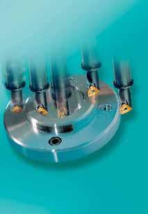
128 126
129 Dreh-Bohr-Werkzeug Pentatec Turning-drilling-tool Pentatec Fünf Bearbeitungsoperationen, ein Werkzeug 128 Five machining operations, one tool Schnittparameter 129 Cutting parameters Klemmhalter 130 Tool holders Wendeschneideplatten 130 Indexable inserts Bezeichnungssystem 131 Designation system LMT-Schneidstoff, Übersicht 131 LMT-carbide grade, overview Konstruktionsmerkmale und weitere Anwendungsmöglichkeiten 132 Additional features and application possibilities Schnittdatenrichtwerte, Dreh-Bohr-Werkzeug Pentatec 134 Cutting data standard values, turing-drilling-tool Pentatec 127
 5. Core Milling (to DIN 74) 3.")


130 Pentatec Dreh-Bohr-Werkzeug Pentatec Turning-drilling-tool 1. Plandrehen 1. Face turning 4. Innenlängsdrehen 4. Internal turning 2. Längsdrehen 2. External turning 5. Senken (nach DIN 74) 5. Core Milling (to DIN 74) 3. Bohren ins Volle mit geradem Bohrgrund 3. Drilling into solid with flat drilling base Fünf Bearbeitungsoperationen, ein Werkzeug Das universelle Dreh-Bohr-Werkzeug ersetzt bis zu fünf ISO- Werkzeuge und reduziert die Bearbeitungszeiten um bis zu 30% durch die Einsparung von Werkzeugwechselzeiten und Werkzeugleerfahrten. Five machining operations, one tool The universal turning-drilling-tool substitutes up to 5 ISO-tools and reduces machining times up to 30% through saving of tool changing times and unnecessary tool movements. 128
131 Pentatec Schnittparameter Pentatec Cutting parameters Längsdrehen 1,50D Longitudinal turning 1,50D a p mm Längsdrehen 2,25D Longitudinal turning 2,25D a p mm ,1 0,2 0,3 f n mm/u 0,1 0,2 0,3 f n mm/u Plandrehen 1,50D Face turning 1,50D Plandrehen 2,25D Face turning 2,25D a p mm a p mm ,1 0,2 f n mm/u 0,3 0,1 0,2 f n mm/u 0,3 Bohren 1,50D/2,25D Drilling 1,50D/2,25D = PT20 = PT18 f n mm/u f n mm/rev = PT15 0,10 0,09 0,08 0,07 0,06 0,05 0,04 0,03 0,02 0,01 PT10 PT15 PT18 *) PT20 = PT10 *) Praxishinweis Bohren: Bei Werkstoffen mit höheren Festigkeiten ( 1000 N/mm 2 ) beim Eintritt mit den niedrigsten Vorschubwerten (fn = 0,01 0,02 mm) beginnen und nach Erreichen einer Bohrtiefe von 1 mm Vorschubwerte laut Tabelle erhöhen. *) Important hint: When drilling into materials having elevated tensile strength ( 1000 N/mm 2 ) start with the lowest feed rates (fn = 0,01 0,02 mm) and after having come to a drilling depth of 1 mm continue with the feed rates according to the table. 129
132 Halter Pentatec Tool holder Pentatec D* d 1 d 2 D* d 1 l 3 l 3 l 4 l 1 l 2 D* = Durchmesser für Senkbohrung laut DIN 174 Diameter for plunge drilling according to DIN 174 Bestellbezeichnung Passende Wendeplatte Ordering Code D* d 1 d 2 l 1 l 2 l 3 l 4 Indexable insert PTR/L 10-2,25D ,5 - WCHX PTR/L 10-1,50D PTR/L 15-2,25D ,75 - WCHX PTR/L 15-1,50D ,5 125 PTR/L 18-2,25D ,5 - WCHX PTR/L 18-1,50D PTR/L 20-2,25D WCHX PTR/L 20-1,50D Bestellbeispiel: 1 Stück PTR15-2,25D-07 Ordering example: 1 off PTR15-2,25D-07 Wendeschneidplatten Pentatec Indexable inserts Pentatec d l 88 r 7 s d 1 Bestellbezeichnung Sorte Ordering Code l d s d 1 r Grade WCHX 05T102EN-BFM 5,0 7,938 1,98 2,8 0,2 LC235C WCHX 05T104EN-BFM 5,0 7,938 1,98 2,8 0,4 LC235C WCHX EN-BFM 7,5 12,0 3,18 3,4 0,4 LC235C WCHX EN-BFM 7,5 12,0 3,18 3,4 0,8 LC235C WCHX EN-BFM 9,0 14,29 3,18 4,4 0,4 LC235C WCHX EN-BFM 9,0 14,29 3,18 4,4 0,8 LC235C WCHX 10T304EN-BFM 10,0 15,875 3,97 5,9 0,4 LC235C WCHX 10T308EN-BFM 10,0 15,875 3,97 5,9 0,8 LC235C Bestellbeispiel: 10 WCHX EN-BFM LC235C Ordering example: 10 off WCHX EN-BFM LC235C Ersatzteile Spare parts Bestellbezeichnung Ordering Code Torx Schraube Screw Schlüssel Key PTR/L 10 A V04-T PTR/L 15 A V04T PTR/L 18 A V04-T PTR/L 20 A V04-T
133 Bezeichnungssystem Pentatec Dsignation system Pentatec P TR20-2, 25D- 10 PENTATEC Wendeplattengröße (WCHX 10T304) Insert size Schnittrichtung Cutting direction R = rechtsschneidend right hand cutting L = linksschneidend left hand cutting Maximale Bohrtiefe bzw. Tiefe für Längsdrehen 2,25 x Nenndurchmesser D Maximum drilling depth or turning length extension (2,25 x nominal diameter D) Nenndurchmesser D (D = 20k13) Nominal diameter Sorte Grade ISO Anwendungsbereich Range of applications Werkstoffgruppe Group of materials Bearbeitungsverfahren Application P M K N S H T M D S G P Stahl Steel Rostfrei Stainless Grauguß Grey cast iron NE-Metalle (Al, etc.) Nonferrous metals Hochwarmfest High temperature materials Harte Werkstoffe Hard materials Drehen Turning Fräsen Milling Bohren Drilling Gewindebearbeitung Threading Einstechen Grooving Abstechen Parting LC235C HC-P35 HC-M35 Anwendungsschwerpunkt Application peak Gesamtbereich nach ISO 513 Full range to ISO Hauptanwendung Main application Weitere Anwendung Further applications Standardsorte Standard grade 131
134 Technische Hinweise Technical hints Weitere Konstruktionsmerkmale und Vorteile Additional features and application possibilities Nebenschneide einsetzbar Secondary cutting edge can be used Bohren ins Volle außer der Mitte Drilling off the centre X: Versatz aus der Mitte Offset D: Nenndurchmesser Werkzeug Nominal tool diameter X = (1,1 x D) - D 2 x D 1,1 x D Werkstück Werkzeug 2,25D/1,50D D min D max Tool PTR/L 10 -x,xxd H13 11 PTR/L 15 -x,xxd H13 16,5 PTR/L 18 -x,xxd H13 19,8 PTR/L 20 -x,xxd H13 22 Anfasen außen External chamfering Anfasen innen Internal chamfering 132
135 Technische Hinweise Technical hints Weitere Konstruktionsmerkmale und Vorteile Additional features and application possibilities Senkbohrung mit Pentatec -Werkzeugen Core drilling with Pentatec -tools Die Durchmesserreihe der Pentatec -Werkzeuge ist so ausgelegt, dass damit Senkbohrungen nach DIN 74 Form H3, J3 und K3 in einem Arbeitsgang produziert werden können. The diameters of the Pentatec -tools are designed to produce counter-bores according to DIN 74 forms H3, J3 and K3 in one operation. Form H3 für: Zylinderschrauben nach DIN 84 und DIN 7984 Gewindeschneidschrauben nach DIN 7513 Form B Gewindefurchende Schrauben nach DIN 7500 Teil1 Form A Form J3 für: Zylinderschrauben nach DIN 6912 (niedriger Kopf, Schlüsselführung) Form K3 für: Zylinderschrauben nach DIN 912 Form H3 for: cheese-head screws according to DIN 84 socket head cap screws to DIN 7984 cheese-head screws according to DIN 7513 form B cheese-head screws according to DIN 7500 part 1 form A Form J3 for: socket head cap screws according to DIN 6912 (low screw head, key guide) Form K3 for: socket head cap screws according to DIN 912 Mit Federring nach DIN 7980 with lock washer according to DIN 7980 Werkzeug 2,25D/1,50D Gewinde Tool Thread D H13 Nenndurchmesser nominal diameter PTR/L 10 -x,xxd- 05 M /+0,220 PTR/L 15 -x,xxd- 07 M /+0,270 PTR/L 18 -x,xxd- 09 M /+0,330 PTR/L 20 -x,xxd- 10 M /+0,330 Große Aufnahmedurchmesser und Plananlage Large mounting diameter and seating face Pentatec PTR20-2,25D Pentatec PTR20-1,50D ISO-Bohrstange ISO-boring bar D min D min Dmin D min d Aufnahme 25/32* d shank * Durchmesser am Bund * Diameter an the flange Plananlage Ja Yes Nein No Nein No Seating face Pentatec -Nutzen: Höhere Stabilität und geringere Vibrationsneigung durch größere Aufnahmedurchmesser und zusätzliche Plananlage bei PT-2,25D Pentatec -benefits: More stability and less tendency to vibrate through larger seating diameters and the additional seating face for PT-2,25D 133
136 Technische Hinweise Schnittdatenrichtwerte, Dreh-Bohr-Werkzeug Pentatec Werkstoff- Gruppe P M Werkstückstoff Unlegierter Stahl 1) Niedrig legierter Stahl 1) Gliederung der Werkstoff-Hauptgruppen und Kennbuchstaben Hochlegierter Stahl und hochleg. Werkzeugstahl Nichtrostender Stahl 1) Nichtrostender Stahl 1) ca 0,15%C geglüht ca 0,45%C geglüht ca 0,45%C vergütet ca 0,75%C geglüht ca 0,75%C vergütet geglüht vergütet vergütet vergütet geglüht gehärtet und angelassen ferritisch / martensitisch geglüht martensitisch vergütet austenitisch 2), abgeschreckt Brinell Härte HB LC235C v c m/min Drehen und Bohren K N S Grauguß Gußeisen mit Kugelgraphit Temperguß Aluminium-Knetlegierungen Aluminium-Gußlegierungen Kupfer und Kupferlegierungen (Bronze / Messing) Nichtmetallische Werkstoffe Warmfeste Legierungen Titanlegierungen perlitisch / ferritisch perlitisch (martensitisch) ferritisch perlitisch ferritisch perlitisch nicht aushärtbar aushärtbar, ausgehärtet 12% Si. nicht aushärtbar 12% Si. aushärtbar, ausgehärtet > 12% Si. nicht aushärtbar Automatenlegierung Pb>1% Messing, Rotguß Bronze, bleifreies Kupfer und Elektrolytkupfer Duroplaste Fasenverstärkte Kunststoffe Hartgummi geglüht ausgehärtet Fe-Basis geglüht Ni- oder Co-Basis ausgehärtet gegossen Reintitan Alpha + Beta- Legierungen, ausgehärtet Rm 3) 400 Rm 3) ) und Stahlguß 2) und austenitische / ferritische 3) Rm = Zugfestigkeit in N/mm 2 4) HRC = Rockwellhärte C 134
137 Technical hints Cutting data standard values, Turning-drilling-tool Pentatec Material group P M Workpiece material Unalloyed steel 1) Low-alloy steel 1) High-alloy steel and high-alloy tool steel 1) Stainless steel 1) Stainless steel 1) Main workpiece material groups and their characteristic letters 0,15%C annealed 0,45%C annealed 0,45%C hardened and temp. 0,75%C annealed 0,75%C hardened and temp. annealed hardened and temp. hardened and temp. hardened and temp. annealed hardened and temp. ferritic / martensitic annealed martensitic hardened and temp. austenitic 2), quenched Brinell hardness HB LC235C v c m/min Turning and Drilling K N S Grey cast iron Nodular graphite cast iron Malleable cast iron Aluminium wrought alloys Aluminium cast alloys Copper and copper alloys (Bronze / Brass) Nonmetallic materials Heat resistant alloys Titanium alloys perlitic / ferritic perlitic (martensitic) ferritic perlitic ferritic perlitic unhardenable hardenable, hardened 12% Si. unhardenable 12% Si. hardenable, hardened > 12% Si. unhardenable Free cutting alloys Pb>1% Brass, Red bronze Bronze, non leaded copper and electrolitic copper Duroplastics Fibre reinforded plastics Hard rubber annealed hardened Fe-based annealed hardened Ni- or Co-based cast Pure titanium Alpha- and Beta-alloys hardened Rm 3) 400 Rm 3) ) and cast steel 2) and austenitic / ferritic 3) Rm = tensile strength in N/mm 2 4) HRC = Rockwell hardness C 135
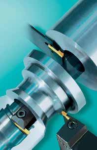
138 136
139 Stechen, Stechdrehen mit Easytec Grooving, Groove-turning with Easytec Systemvorteile Easytec 138 Advantages of the system Easytec Programmübersicht Tool range Klemmhalter und Wendeplatten für das Abstechen und Außen Einstechen 140 Tool holders and indexable inserts for parting and external grooving Klemmhalter und Wendeplatten für das Außen Einstechen, Stechdrehen, 140 Profildrehen und Freistechen Tool holders and indexable inserts for external grooving, groove-turning, profiling and undercutting Klemmhalter und Wendeplatten für das Axial Einstechen und Stechdrehen 141 Tool holders and indexable inserts for face grooving and groove-turning Klemmhalter und Wendeplatten für das Innen Einstechen, Stechdrehen, 141 Formdrehen und Freistechen Tool holders and indexable inserts for internal grooving, groove-turning, profiling and undercutting Spanformstufengeometrien Chip groove geometries für das Ein- und Abstechen 142 for parting and grooving für das Stechen und Stechdrehen 143 for grooving and groove-turning für das Profildrehen 144 for profile turning für das Kopierdrehen von Aluminium 145 for copying aluminium Bezeichnungssysteme Systems of designation für Wendeschneidplatten 146 for indexable inserts für Klemmhalter zur Außenbearbeitung 148 for tool holders, external machining für Klemmhalter zur Innenbearbeitung 150 for tool holders, internal machining Wendeschneidplatten 152 Indexable inserts Sonderprofilplatten 164 Inserts with special profile Spannblock, Klingen 166 Parting holder, parting blades Klemmhalter 168 Tool holders Technische Hinweise Technical hints Stechen 178 Grooving Stechdrehen 182 Groove-turning Maßnahmen bei Bearbeitungsproblemen Stechen, Stechdrehen 185 Options against machining problems, grooving, groove-turning LMT-Schneidstoffsorten Stechen, Stechdrehen: Übersicht, Einsatzbereiche 186 LMT-Cutting materials, grooving, groove-turning: overview, application possibilities 187 Schnittdatenrichtwerte Ein- und Abstechen 188 Cutting data standard values, parting and grooving 190 Schnittdatenrichtwerte Stechdrehen 192 Cutting data standard values, groove-turning
140 Systemvorteile Easytec Advantages of the system Easytec Stech- und Drehsystem zugleich reduzieren Ihre Lagerhaltung. A grooving and turning system all in one. Reduces your stock. Einfacher Aufbau reduziert Fehlermöglichkeiten in der Anwendung. Simple setup. Reduces possibilities of errors in the application. Hohe Stabilität durch doppelte U-Führung und lange Schneidplatten erhöht Ihre Prozeßsicherheit. High stability through double U-clamp and long inserts. Increases your process security. DIN 912 (ISO) Ersatzteile sind Normteile, das reduziert Ersatzteilkosten. Spare parts are standard part. Reduces costs for spare parts. Stechen mit Easytec Grooving with Easytec T T Ein- und Zweiseitige Schneidplatten: ES... und ED..., bei kleinen Stechtiefen noch wirtschaftlicher. Single and double ended inserts ES... and ED..., more economical with shallow grooving cuts. Direktgepreßte Schneidplatten senken Ihre Produktionskosten. Directly pressed inserts reduce production costs. Zwei Spanformergeometrien: GM, GF. Für jede Anwendung die richtige Schneide Two chip former geometries: GM, GF. Inserts to suit all applications. 138
141 Systemvorteile Easytec Advantages of the system Easytec Schräge Hauptschneide möglich:...r4,...l4,...r6,...l6,...r15,...l15. Reduziert Grat- und Butzenbildung Angled main cutting edge available...r4,...l4,...r6,...l6,...r15,...l15. Formation of sharp edges and burrs is reduced. Stechdrehen mit Easytec Groove-turning with Easytec Ersetzt bis zu drei Werkzeuge und reduziert Ihre Lagerhalterung. It replaces up to 3 tools and reduces your stock Eliminiert nahezu sämtliche Nebenzeiten. 95% statt 50% Eingriffszeit. Keine leeren Kilometer! Reduction of non cutting times. 95 % instead 50 % effective time. No empty miles! +/-0,1 +/-0,025 LC MR LCG R Direktgepreßte und geschliffene Schneidplatten:...LCMR...,...LCGR... Für jede Aufgabe eine Lösung. Direct pressed and ground inserts:...lcmr...,...lcgr... A solution for any application. Zwei Spanformergeometrien: TM, TA. Für jede Anwendung die richtige Schneide. Two chip former geometries: TM, TA. Inserts to suit all applications. Gerade und runde Schneiden:...LCGR...,...RCGR... je nachdem, ob Sie Drehen oder Kopieren. Straight and round cutting edges...lcgr...,...rcgr... depending on whether the machining is turning or copying. Hohe Oberflächengüte beim Längsdrehen durch Wiper-Effekt erhöht Produktivität und ersetzt Schleifoperationen. High surface quality on longitudinal turning through wiper-effect. Increased productivity and may replace grinding. 139
142 Programmübersicht Program range Werkzeuge und Wendeplatten Tool holders and indexable inserts Abstechen und außen Einstechen Parting and external grooving Schnittrichtung Anstellwinkel Werkzeug Seite Wendeplatte Seiten Cutting direction Setting angle Tool Page Indexable Insert Pages PH PB ED LC , 153 ES LC , CGFCR/L...E , 169 ED LC Außen Einstechen, Stechdrehen, Profildrehen und Freistechen External grooving, groove-turning, profiling and undercutting Schnittrichtung Anstellwinkel Werkzeug Seite Wendeplatte Seiten Cutting direction Setting angle Tool Page Indexable Insert Pages 0 CGFCR/L...E ED LC , ED RC , CGFCR/L...F ED LC CGSCR/L...E ED RC , 163 ID RC
143 Programmübersicht Program range Werkzeuge und Wendeplatten Tool holders and indexable inserts Axial Einstechen und Stechdrehen Face grooving and groove-turning Schnittrichtung Anstellwinkel Werkzeug Seite Wendeplatte Seiten Cutting direction Setting angle Tool Page Indexable Insert Pages 90 CGACR/L...F FD LC ED LC , CGACR/L...F FD LC ED LC CGFCR/L...F FD LC ED LC , CGFCR/L...F FD LC ED LC Innen Einstechen, Stechdrehen, Formdrehen und Freistechen Internal grooving, grooveturning, profiling and undercutting Schnittrichtung Anstellwinkel Werkzeug Seite Wendeplatte Seiten Cutting direction Setting angle Tool Page Indexable Insert Pages 90 A..CGACR/L...I 176 ID LC ID RC E. RC S..CGSCR/L...I 177 ID RC E. RC
144 Spanformstufengeometrien Chip former geometries Spanformstufen zum Ein- und Abstechen Geometries for parting and grooving - GM (Grooving Medium), - GF (Grooving Fine) - GM (Grooving Medium), - GF (Grooving Fine) Kontrollierte Spanformung über einen breiten Anwendungsbereich. Controlled chip forming over a wide range of application. Stechen Parting E. LC... GM 6 0,10 0,40 5 0,09 0,35 Schneidenbreite mm Width of cutting edge mm ,075 0,07 0,05 0,18 0,25 0,30 0,02 0,06 0,10 0,15 0,20 0,25 0,30 0,35 0,40 Vorschub f (mm/u) Feed f (mm/rev) Stechen Parting E. LC... GF 6 0,04 0,22 5 0,04 0,20 Schneidenbreite mm Width of cutting edge mm ,04 0,18 0,04 0,16 0,04 0,12 0,02 0,06 0,10 0,15 0,20 0,25 0,30 0,35 0,40 Vorschub f (mm/u) Feed f (mm/rev) Startwert Starting value 142
145 Spanformstufengeometrien Chip former geometries Spanformstufe zum Stechen und Stechdrehen Chip former for grooving and groove-turning - TM (Turning Medium) - TM (Turning Medium) Kontrollierte Spanformung über einen breiten Anwendungsbereich. Controlled chip forming over a wide range of application. ED LC TM ED LC TM Schnittiefe a p Depth of cut a p (mm) 5,0 4,0 3,0 2,0 1,0 0,5 Drehen Turning Schnittiefe a p Depth of cut a p (mm) 5,0 4,0 3,0 2,0 1,0 0,5 Drehen Turning 0,00 0,10 0,20 0,30 0,40 0,50 0,60 Vorschub f (mm/u) Feed f (mm/rev) 0,00 0,10 0,20 0,30 0,40 0,50 0,60 Vorschub f (mm/u) Feed f (mm/rev) 0,00 0,10 0,20 0,30 0,40 0,50 0,60 3 mm 0,00 0,10 0,20 0,30 0,40 0,50 0,60 4 mm 0,07 0,25 Stechen Grooving 0,075 0,30 Stechen Grooving ED LC TM ED LC TM Schnittiefe a p Depth of cut a p (mm) 5,0 4,0 3,0 2,0 1,0 0,5 Drehen Turning Schnittiefe a p Depth of cut a p (mm) 5,0 4,0 3,0 2,0 1,0 0,5 Drehen Turning 0,00 0,10 0,20 0,30 0,40 0,50 0,60 Vorschub f (mm/u) Feed f (mm/rev) 0,00 0,10 0,20 0,30 0,40 0,50 0,60 5 mm 0,00 0,10 0,20 0,30 0,40 0,50 0,60 Vorschub f (mm/u) Feed f (mm/rev) 0,00 0,10 0,20 0,30 0,40 0,50 0,60 6 mm 0,09 0,35 Stechen Grooving 0,10 0,40 Stechen Grooving Startwert Starting value 143
146 Spanformstufengeometrien Chip former geometries Spanformstufe zum Profildrehen Chipformer for profiling R... - TM (Turning Medium) R... - TM (Turning Medium) Kontrollierte Spanformung über einen breiten Anwendungsbereich. Controlled chip forming over a wide range of application. Schnittiefe a p Depth of cut a p (mm) 5,0 4,0 3,0 2,0 1,0 0,5 ED RC TM Drehen Turning Schnittiefe a p Depth of cut a p (mm) 5,0 4,0 3,0 2,0 1,0 0,5 ED RC TM Drehen Turning 0,00 0,10 0,20 0,30 0,40 0,50 0,60 Vorschub f (mm/u) Feed f (mm/rev) 0,00 0,10 0,20 0,30 0,40 0,50 0,60 3 mm 0,00 0,10 0,20 0,30 0,40 0,50 0,60 Vorschub f (mm/u) Feed f (mm/rev) 0,00 0,10 0,20 0,30 0,40 0,50 0,60 4 mm 0,05-0,15 Stechen Grooving 0,05-0,15 Stechen Grooving ED RC TM ED RC TM Schnittiefe a p Depth of cut a p (mm) 5,0 4,0 3,0 2,0 1,0 0,5 Drehen Turning Schnittiefe a p Depth of cut a p (mm) 5,0 4,0 3,0 2,0 1,0 0,5 Drehen Turning 0,00 0,10 0,20 0,30 0,40 0,50 0,60 Vorschub f (mm/u) Feed f (mm/rev) 0,00 0,10 0,20 0,30 0,40 0,50 0,60 5 mm 0,00 0,10 0,20 0,30 0,40 0,50 0,60 Vorschub f (mm/u) Feed f (mm/rev) 0,00 0,10 0,20 0,30 0,40 0,50 0,60 6 mm 0,05-0,175 Stechen Grooving 0,05-0,20 Stechen Grooving Startwert Starting value 144
147 Spanformstufengeometrien Chip former geometries Spanformstufe zum Kopierdrehen von Aluminium Chip former for copying aluminium - TA (Turning Aluminium) - TA (Turning Aluminium) Kontrollierte Spanformung über einen breiten Anwendungsbereich. Controlled chip forming over a wide range of application. Schnittiefe a p Depth of cut a p (mm) 5,0 4,0 3,0 2,0 1,0 0,5 ED RC TA 0,00 0,10 0,20 0,30 0,40 0,50 0,60 Vorschub f (mm/u) Feed f (mm/rev) Drehen Turning 6 mm Stechen Grooving Schnittiefe a p Depth of cut a p (mm) 5,0 4,0 3,0 2,0 1,0 0,5 ED RC TA 0,00 0,10 0,20 0,30 0,40 0,50 0,60 Vorschub f (mm/u) Feed f (mm/rev) 0,00 0,10 0,20 0,30 0,40 0,50 0,60 Drehen Turning 8 mm 0,00 0,10 0,20 0,30 0,40 0,50 0,60 0,15-0,275 0,15-0,30 Stechen Grooving Startwert Starting value 145
148 Bezeichnungssystem Designationsystem für Wendeplatten for inserts E Bearbeitungsart Type of machining D Schneidenanzahl Number of cutting edges L Wendeplattenform Indexable insert shape C Freiwinkel Clearence angle G Toleranzklasse Tolerance class E D L C G 7 +/- 0,025 mm Außen External Zwei Two Gerade Straight M I S R +/- 0,1 mm Innen Internal Eine One Rund Round F Axial Axial 146
149 R Plattentype Type of insert Stechbreite mm Grooving width mm 0.4 Eckenradius mm Corner radius mm N Schnittrichtung Cutting direction O Anstellwinkel Approach angle N w w r L E. LC : Ohne Spanformrille Without chip-former groove R F. LC : Mit Spanformrille With chip-former groove w = 1,00 w = 1,30 w = 1,60 w = 1,85 w = 2,00 w = 2,15 w = 2,65 w = 3,00 w = 3,15 w = 4,00 w = 4,15 w = 4,78 w = 5,00 w = 5,15 w = 6,00 w = 8,00 r = 0,00 r = 0,10 r = 0,15 r = 0,20 r = 0,30 r = 0,40 r = 0,55 r = 0,80 r = 1,20 r = 1,50 r = 2,00 r = 2,39 r = 2,50 r = 3,00 r = 4,00 Links Left hand N Neutral Neutral R E. LC : E. LC : = 0 = 4 = 6 =15 F. LC : Rechts Right hand 147
150 Bezeichnungssystem Designationsystem für Klemmhalter, Außenbearbeitung for tool holders, external work C Befestigungsart Type of fixation G Wendeplattentyp Type of insert F Klemmhalterform Shape of tool holder C Freiwinkel Clearence angle R Schnittrichtung Direction of cut 20 Schneidehöhe mm Height of cutting edge mm C G A C L h Von oben geklemmt Fixation from above Stechplatte Grooving insert F 0 Links Left hand R Rechts Right hand S
151 20 Schaftbreite mm Width of shank mm K Werkzeuglänge Length of tool 2 Wendeplattengröße Size of insert w w E Bearbeitungsart Type of work E 12.0 Stechtiefe mm Depth of groove mm D50 Kleinster Aussendurchmesser mm Minimum external diameter mm T max l 1 D min b Außen External A B C D E F G H J K M N P Q R S T U V W Y X l 1 mm 32 mm 40 mm 50 mm 60 mm 70 mm 80 mm 90 mm 100 mm 110 mm 125 mm 150 mm 160 mm 170 mm 180 mm 200 mm 250 mm 300 mm 350 mm 400 mm 450 mm 500 mm Sonderlänge Other length w mm F Axial Axial T max 149
152 Bezeichnungssystem Designationsystem für Klemmhalter, Innenbearbeitung for tool holders, internal work C Haltertyp Type of bar 20 Stangendurchmesser Diameter of shank N Werkzeuglänge Length of tool C Befestigungsart Type of clamping G Wendeplattentyp Insert type A Klemmhalterform Shape of tool holder A C G A Stahlschaft, mit innerer Kühlmittelzufuhr. Steel shank, with internal coolant supply. d l 1 90 S Stahlschaft, ohne besondere Konstruktionsmerkmale. Steel shank with no special construction characteristics. d l 1 mm Von oben geklemmt Fixation from above Stechplatte Grooving insert S 45 A B C D E F G H J K M N P Q R S T U V W Y X 32 mm 40 mm 50 mm 60 mm 70 mm 80 mm 90 mm 100 mm 110 mm 125 mm 150 mm 160 mm 170 mm 180 mm 200 mm 250 mm 300 mm 350 mm 400 mm 450 mm 500 mm Sonderlänge Other length 150
153 C Freiwinkel Clearence angle R Schnittrichtung Direction of cut 2 Wendeplattengröße Size of insert I Bearbeitungsart Type of work 6.5 Stechtiefe mm Depth of groove mm C L w w I 7 T max Links Left hand R Rechts Right hand w mm Innen Internal 151
154 Wendeplatten, Außen Einstechen und Abstechen bis Plattenlänge Inserts, external grooving and parting up to length of insert l +/-0,1 1 7 s r Tmax w ED LCMR...N0 GM Bestellbezeichnung Ordering Code w +/- r l 1 s T max HM-Sorte Grade LC232F LC242W LC442W 0,05 ED LCMR N0 GM 2,0 0, ,7 19 ED LCMR N0 GM 3,0 0, ,7 19 ED LCMR N0 GM 4,0 0, ,7 19 ED LCMR N0 GM 5,0 0, ,2 24 ED LCMR N0 GM 6,0 0, ,2 24 LCM02 LDP091 LW612 ED LCMR...L...GM ED LCMR L6 GM 2,0 0, ,7 19 ED LCMR L6 GM 3,0 0, ,7 19 ED LCMR L4 GM 4,0 0, ,7 19 ED LCMR L4 GM 5,0 0, ,2 24 ED LCMR R GM ED LCMR R6 GM 2,0 0, ,7 19 ED LCMR R6 GM 3,0 0, ,7 19 ED LCMR R4 GM 4,0 0, ,7 19 ED LCMR R4 GM 5,0 0, ,2 24 Passende Werkzeuge Suitable holders PB CGFC E CGFC E Seite Page 167 Seite Page 169 Seite Page 168 Bestellbeispiel Order Example: 10 Stück off ED LCMR N0 GM LC242W Verfügbar ab Lager Available from stock Schnittdatenrichtwerte siehe Seiten 188, 192 For cutting data standard values see pages 190,
155 Wendeplatten, Außen Einstechen und Abstechen bis Plattenlänge Inserts, external grooving and parting up to length of insert +/-0,1 7 l 1 HM-Sorte Grade s r Tmax w ED LCMR N0 GF Bestellbezeichnung Ordering Code w +/- r l 1 s T max LC232F LC242W LC442W 0,05 ED LCMR N0 GF 2,0 0, ,7 19 ED LCMR N0 GF 3,0 0, ,7 19 ED LCMR N0 GF 4,0 0, ,7 19 ED LCMR N0 GF 5,0 0, ,2 24 ED LCMR N0 GF 6,0 0, ,2 24 LCM02 LDP091 LW612 ED LCMR L GF ED LCMR R GF ED LCMR L6 GF 2,0 0, ,7 19 ED LCMR L15 GF 2,0 0, ,7 19 ED LCMR L6 GF 3,0 0, ,7 19 ED LCMR L15 GF 3,0 0, ,7 19 ED LCMR L4 GF 4,0 0, ,7 19 ED LCMR L15 GF 4,0 0, ,7 19 ED LCMR L4 GF 5,0 0, ,2 24 ED LCMR R6 GF 2,0 0, ,7 19 ED LCMR R15 GF 2,0 0, ,7 19 ED LCMR R6 GF 3,0 0, ,7 19 ED LCMR R15 GF 3,0 0, ,7 19 ED LCMR R4 GF 4,0 0, ,7 19 ED LCMR R15 GF 4,0 0, ,7 19 ED LCMR R4 GF 5,0 0, ,2 24 Passende Werkzeuge Suitable holders PB CGFC E CGFC E Seite Page 167 Seite Page 169 Seite Page 168 Bestellbeispiel Order Example: 10 Stück off ED LCMR N0 GF LC242W Verfügbar ab Lager Available from stock Schnittdatenrichtwerte siehe Seite 188, 192 For cutting data standard values see pages 190,
156 Wendeplatten, Außen Einstechen und Abstechen, große Tiefen Inserts, external grooving and parting, greater depths l 1 +/-0,1 7 s r w ES LCMR...N0 GM Bestellbezeichnung Ordering Code w +/- r l 1 s T max HM-Sorte Grade LC232F LC242W LC442W 0,05 ES LCMR N0 GM 2,0 0, ,7 ES LCMR N0 GM 3,0 0, ,7 ES LCMR N0 GM 4,0 0, ,7 ES LCMR N0 GM 5,0 0, ,2 ES LCMR N0 GM 6,0 0, ,2 LCM02 LDP091 LW612 ES LCMR...L...GM ES LCMR L6 GM 2,0 0, ,7 ES LCMR L6 GM 3,0 0, ,7 ES LCMR L4 GM 4,0 0, ,7 ES LCMR R GM ES LCMR R6 GM 2,0 0, ,7 ES LCMR R6 GM 3,0 0, ,7 ES LCMR R4 GM 4,0 0, ,7 Passende Werkzeuge Suitable holders PB Seite Page 167 Bestellbeispiel Order Example: 10 Stück off ES LCMR N0 GM LC242W Verfügbar ab Lager Available from stock Schnittdatenrichtwerte siehe Seite 188 For cutting data standard values see pages
157 Wendeplatten, Außen Einstechen und Abstechen, große Tiefen Inserts, external grooving and parting, greater depths l 1 +/-0,1 7 s r w ES LCMR N0 GF Bestellbezeichnung Ordering Code w +/- r l 1 s T max HM-Sorte Grade LC232F LC242W LC442W 0,05 ES LCMR N0 GF 2,0 0, ,7 ES LCMR N0 GF 3,0 0, ,7 ES LCMR N0 GF 4,0 0, ,7 ES LCMR N0 GF 5,0 0, ,2 ES LCMR N0 GF 6,0 0, ,2 LCM02 LDP091 LW612 ES LCMR L GF ES LCMR R GF ES LCMR L6 GF 2,0 0, ,7 ES LCMR L15 GF 2,0 0, ,7 ES LCMR L6 GF 3,0 0, ,7 ES LCMR L15 GF 3,0 0, ,7 ES LCMR L4 GF 4,0 0, ,7 ES LCMR L15 GF 4,0 0, ,7 ES LCMR R6 GF 2,0 0, ,7 ES LCMR R15 GF 2,0 0, ,7 ES LCMR R6 GF 3,0 0, ,7 ES LCMR R15 GF 3,0 0, ,7 ES LCMR R4 GF 4,0 0, ,7 ES LCMR R15 GF 4,0 0, ,7 Passende Werkzeuge Suitable holders PB Seite Page 167 Bestellbeispiel Order Example: 10 Stück off ES LCMR N0 GF LC242W Verfügbar ab Lager Available from stock Schnittdatenrichtwerte siehe Seite 188 For cutting data standard values see pages
158 Wendeplatten, Außen Einstechen, kleine Tiefen Inserts, external grooving, small depths +/-0,025 7 l1 HM-Sorte Grade s r Tmax w b ED LCGR... TM Bestellbezeichnung Ordering Code w +/- r +/- 0,03 b l 1 s T max LC232F LC242W LC442W 0,02 ED LCGR TM 1,00 0,00 2,2 20 4,7 2 ED LCGR TM 1,30 0,00 2,2 20 4,7 2 ED LCGR TM 1,60 0,10 2,2 20 4,7 2 ED LCGR TM 1,85 0,10 2,2 20 4,7 3 ED LCGR TM 2,15 0,15 2,2 20 4,7 3 ED LCGR TM 2,65 0,15 2,2 20 4,7 5 ED LCGR TM 3,15 0,15 2,2 20 4,7 5 ED LCGR TM 4,15 0,15 3,0 20 4,7 5 ED LCGR TM 5,15 0,15 4,0 25 5,2 5 LCM02 LDP091 LW612 Passende Werkzeuge (detaillierte Zuordnung zu den einzelnen Stechbreiten siehe Seite 175) Suitable holders (detailed assignment to the individual grooving widths see page 175) CGFC E CGFC E CGFC F CGAC F Seite Page 169 Seite Page 168 Seite Page 173 Seite Page 174 Bestellbeispiel Order Example: 10 Stück off ED LCGR TM LC232F Verfügbar ab Lager Available from stock Schnittdatenrichtwerte siehe Seiten 188, 192 For cutting data standard values see pages 190,
159 Wendeplatten, Außen Einstechen und Stechdrehen Inserts, external grooving and groove-turning +/-0,1 l 1 7 s r w b ED LCMR... TM Bestellbezeichnung Ordering Code w +/- r b l 1 s HM-Sorte Grade LC232F LC242W LC442W 0,05 ED LCMR TM 3,0 0,40 2,2 20 4,7 ED LCMR TM 4,0 0,40 3,0 20 4,7 LCM02 LDP091 LW612 ED LCMN ED LCMN ,0 0,40 3,0 20 4,7 ED LCMN ,0 0,80 5,0 25 5,2 Passende Werkzeuge Suitable holders CGFC E CGFC F Seite Page 169 Seite Page 173 Bestellbeispiel Order Example: 10 Stück off ED LCMR TM LC232F Verfügbar ab Lager Available from stock Schnittdatenrichtwerte siehe Seiten 188, 192 For cutting data standard values see pages 190,
160 Wendeplatten, Außen Einstechen und Stechdrehen Inserts, external grooving and groove-turning +/-0,025 l 1 7 s r w b ED LCGR...TM Bestellbezeichnung Ordering Code w +/- r +/- 0,05 b l 1 s HM-Sorte Grade LC232F LC242W LC442W 0,02 ED LCGR TM 3,0 0,40 2,2 20 4,7 ED LCGR TM 4,0 0,40 3,0 20 4,7 ED LCGR TM 4,0 0,80 3,0 20 4,7 ED LCGR TM 5,0 0,40 4,0 25 5,2 ED LCGR TM 5,0 0,80 4,0 25 5,2 ED LCGR TM 6,0 0,80 5,0 25 5,2 ED LCGR TM 6,0 1,20 5,0 25 5,2 ED LCGR TM 8,0 0,80 6,0 30 6,4 ED LCGR TM 8,0 1,20 6,0 30 6,4 LCM02 LDP091 LW612 Passende Werkzeuge Suitable holders CGFC E CGFC F Seite Page 169 Seite Page 173 Bestellbeispiel Order Example: 10 Stück off ED LCGR TM LC232F Verfügbar ab Lager Available from stock Schnittdatenrichtwerte siehe Seiten 188, 192 For cutting data standard values see pages 190,
161 Wendeplatten, Außen Einstechen, Stechdrehen, Profildrehen und Freidrehen Inserts, external grooving, groove-turning, profiling and undercutting +/-0,025 l 1 7 s r w b ED RCGR... TM Bestellbezeichnung Ordering Code w +/- r +/- b l 1 s HM-Sorte Grade LC232F LC242W LC442W 0,02 0,05 ED RCGR 3.00 TM 3,0 1,50 2,2 20 4,7 ED RCGR 4.00 TM 4,0 2,00 3,0 20 4,7 ED RCGR 5.00 TM 5,0 2,50 4,0 25 5,2 ED RCGR 6.00 TM 6,0 3,00 5,0 25 5,2 LCM02 LDP091 LW612 Passende Werkzeuge Suitable holders CGFC E CGSC E CGFC F Seite Page 169 Seite Page 170 Seite Page 173 Bestellbeispiel Order Example: 10 Stück off ED RCGR 3.00 TM LC232F Verfügbar ab Lager Available from stock Schnittdatenrichtwerte siehe Seiten 188, 192 For cutting data standard values see pages 190,
162 Wendeplatten, Axial Einstechen und Stechdrehen Inserts, axial grooving and groove-turning 12 +/-0,1 4 7 l1 HM-Sorte Grade s r w b FD LCMR...L TM Bestellbezeichnung Ordering Code w +/- r b l 1 s LC232F LC242W LC442W LCM02 LDP091 LW612 0,05 FD LCMR L TM 3,0 0,40 2,2 20 4,7 FD LCMR L TM 4,0 0,40 3,0 20 4,7 FD LCMR...R TM FD LCMR R TM 3,0 0,40 2,2 20 4,7 FD LCMR R TM 4,0 0,40 3,0 20 4,7 FD LCMN...L FD LCMN L 4,0 0,40 3,0 20 4,7 FD LCMN...R FD LCMN R 4,0 0,40 3,0 20 4,7 Passende Werkzeuge Suitable holders CGFC F CGAC F CGFC F CGAC F Seite Page 171 Seite Page 172 Seite Page 173 Seite Page 174 Bestellbeispiel Order Example: 10 Stück off FD LCMR L TM LC232F Verfügbar ab Lager Available from stock Schnittdatenrichtwerte siehe Seiten 188, 192 For cutting data standard values see pages 190,
163 Wendeplatten, Innen Einstechen und Stechdrehen Inserts, internal grooving and groove-turning 7 s r w +/-0,025 l1 b ID LCGR... TM ID LCMN +/- 0,1 Bestellbezeichnung Ordering Code w +/- r +/- b l 1 s HM-Sorte Grade LC232F LC242W LC442W 0,02 0,05 ID LCGR TM 3,0 0,40 2,2 20 4,7 ID LCGR TM 4,0 0,40 3,0 20 4,7 ID LCGR TM 4,0 0,80 3,0 20 4,7 ID LCGR TM 5,0 0,40 4,0 25 5,2 ID LCGR TM 5,0 0,80 4,0 25 5,2 ID LCGR TM 6,0 0,80 5,0 25 5,2 ID LCGR TM 6,0 1,20 5,0 25 5,2 ID LCGR TM 8,0 0,80 6,0 30 6,4 ID LCGR TM 8,0 1,20 6,0 30 6,4 w +/- r b l 1 s 0,05 ID LCMN ,0 0,40 3,0 20 4,7 ID LCMN ,0 0,80 5,0 25 5,2 LCM02 LDP091 LW612 Passende Werkzeuge Suitable holders A CGAC I Seite Page 176 Bestellbeispiel Order Example: 10 Stück off ID LCGR TM LC232F Verfügbar ab Lager Available from stock Schnittdatenrichtwerte siehe Seiten 188, 192 For cutting data standard values see pages 190,
164 Wendeplatten, Innen Einstechen, Stechdrehen, Profildrehen und Freistechen Inserts, internal grooving, groove-turning, profiling and undercutting +/-0,025 l 1 s r w b ID RCGR... TM Bestellbezeichnung Ordering Code w +/- r +/- 0,05 b l 1 s HM-Sorte Grade LC232F LC242W LC442W 0,02 ID RCGR 3.00 TM 3,0 1,5 2,2 20 4,7 ID RCGR 4.00 TM 4,0 2,0 3,0 20 4,7 ID RCGR 5.00 TM 5,0 2,5 4,0 25 5,2 ID RCGR 6.00 TM 6,0 3,0 5,0 25 5,2 LCM02 LDP091 LW612 Passende Werkzeuge Suitable holders A CGAC I S CGSC I Seite Page 176 Seite Page 177 Bestellbeispiel Order Example: 10 Stück off ID RCGR 3.00 TM LC232F Verfügbar ab Lager Available from stock Schnittdatenrichtwerte siehe Seiten 188, 192 For cutting data standard values see pages 190,
165 Wendeplatten, Profildrehen Aluminium Inserts, aluminium profiling +/-0,025 7 l 1 HM-Sorte Grade s r w b ED RCGR... TA Bestellbezeichnung Ordering Code w +/- r +/- b l 1 s LC232F LC242W LC442W 0,02 0,05 ED RCGR 6.00 TA 6,0 3,0 5, ,2 ED RCGR 8.00 TA 8,0 4,0 6, ,4 LCM02 LDP091 LW612 ES RCGN ES RCGN ,0 3,0 5, ,2 ES RCGN ,0 4,0 6, ,4 Passende Werkzeuge Suitable holders CGFC E CGSC E A CGAC I S CGSC I Seite Page 169 Seite Page 170 Seite Page 176 Seite Page 177 Bestellbeispiel Order Example: 10 Stück off ED RCGR 6.00 TA LW612 Verfügbar ab Lager Available from stock Schnittdatenrichtwerte siehe Seiten 192 For cutting data standard values see pages

166 Wendeplatten mit Sonderprofilen Inserts with special profile Häufig wiederkehrende Profile? Hohe Genauigkeit der Profile? Komplexe Profile? Frequently required profiles? High precision of the profiles? Difficult? Ab 10 Stück: Profilwendeplatten nach Ihren Vorgaben. 10 Pieces or more: Profile inserts according to your design. Anfragen bitte mit nebenstehendem Blatt. Please use the form on the opposite page for your enquiry. Übliche Toleranzen Usual tolerances Stechbreite Grooving width +/- 0,02 mm Radien und Fasen Radii and chamfers +/- 0,05 mm Winkel Angles +/- 0,5 Profiltiefe Profile depth + 0,1 mm Innenradius Inside radius mind. 0,1 mm 164
167 Fax-Anfrage/Profilwendeplatte Fax-Enquiry/profile insert Absender Sender Firma Company Name Name Abteilung Department Straße Street PLZ/Ort Town & Post Code Tel. Fax Bearbeitung Machining Außen External Innen Internal Axial Axial Werkstoff Material Kleinster Durchmesser Least diameter mm Handskizze des bemaßten Teileprofiles/Maßstab 10 : 1 Hand drawing of the part profile, measured/scale 10 : 1 Beispiel: Example: 8 3, R 1,2 6 4,0 R 1,0 2,0 5 R 0,5 5,0 0-0, mm Seite einfach kopieren, ausfüllen und faxen Please copy this sheet, fill in and fax 165
168 Spannblock, Außen Einstechen und Abstechen, große Tiefen Parting holder, external grooving and parting, greater depths PH (Parting Holder) PH (Parting Holder) PH.. b2 h1 h 3 h 2 h Bestellbezeichnung Ordering Code h 3 h 1 h 2 h 4 h b 2 l 1 b 1 b Klingen Suitable blades PH , , PB 26-. PH , , PH , , PB 32-. PH , , PH , , b b1 h 4 l 1 Ersatzteile Spare parts Bestellbezeichnung Ordering Code Schraube Screw Schlüssel Key SW AF PH M6x25 DIN 912 V01-A PH M6x40 DIN 912 V01-A Passende Klingen Lame PB... Seite Page 167 Bestellbeispiel Order Example: 1 Stück off PH Schnittdatenrichtwerte siehe Seite 188 For cutting data standard values see pages
169 Klingen, Außen Einstechen und Abstechen, große Tiefen Parting blades, external grooving and parting, greater depths PB (Parting Blade) PB (Parting Blade) PB 26-. ø Dmax w Bestellbezeichnung Ordering Code h l 1 h 1 b w D max Schneideinsatz Insert Spannblock Parting holder PB ,4 1,6 1) 2,0-2,2 39 ED LCMR...GM PH..-26 PB ,4 2,4 2,4-3,3 70 ED LCMR...GF PB ,4 3,2 3,6-4,2 80 ES LCMR...GM ES LCMR...GF h 1 h l1 b 150 PB 32-. ø Dmax w h1 h PB ,8 1,6 1) 1,9-2,5 40 ED LCMR...GM PH..-32 PB ,8 2,4 2,4-3,3 100 ED LCMR...GF PB ,8 3,2 3,2-4,3 100 ES LCMR...GM PB ,8 4,0 4,2-5,3 120 ES LCMR...GF PB ,8 5,2 5,2-6,3 120 l 1 b 150 Ersatzteile Spare parts Bestellbezeichnung Ordering Code Schlüssel 2) Key 2) VO7-E1230 Passende Wendeplatten Suitable inserts ED LC...GM/GF ES LC...GM/GF Seiten Pages 152, 153 Seiten Pages 154, 155 Bestellbeispiel Order Example: 1 Stück off PB ) Breite nur im Stechtiefenbereich, durchgängige Breite ist 2,4 mm 1) Width only in grooving depth area, width of the body of the blade is 2,4 mm 2) Schlüssel ist nicht im Lieferumfang enthalten. Bei Bedarf bitte separat bestellen 2) Key is not included in the delivery. If necessary, please order separate Schnittdatenrichtwerte siehe Seiten 188 For cutting data standard values see pages
170 Klemmhalter, Abstechen und Einstechen Tool holders for parting and grooving CGFC...E...D f w h1 Dmax l2 Bestellbezeichnung Ordering Code h 1 b l 1 f l 2 b 1 w h 2 h 3 D max Schneideinsatz Inserts CGFCR/L 1010 K2 E D , ,55 1,0-3,15 17, ED LCMR...GM CGFCR/L 1212 K2 E D , ,55 1,0-3, ED LCMR...GF CGFCR/L 1414 K2 E D , ,55 1,0-3, ED LCGR...TM CGFCR/L 1616 K2 E D , ,55 1,0-3, h3 l1 b h1 h 2 b1 Ersatzteile Spare parts Bestellbezeichnung Ordering Code WSP Breite Size of insert Schraube Screw Schlüssel Key Torx V02-T1500 T15 Passende Wendeplatten (*) detaillierte Zuordnung der Halter zu den einzelnen Stechbreiten siehe Seite 175) Suitable inserts (*) detailed assignment of holders to the individual grooving widths see page 175) ED LC...GM/GF ED LC...TM *) Seiten Pages 152, 153 Seite Page 156 Bestellbeispiel Order Example: 1 Stück off CGFCR 1212 K2 E D24 Schnittdatenrichtwerte siehe Seiten 188 For cutting data standard values see pages
171 Klemmhalter, Abstechen, Einstechen, Stechdrehen, Profildrehen Tool holders for parting, grooving, groove-turning, profiling CGFC...E... f h 1 w Tmax b h 1 l 2 7 l 1 Bestellbezeichnung Ordering Code h 1 b l 1 f l 2 b 1 w T max Schneideinsatz Inserts CGFCR/L 1616 J2 E , ,6 2,0-2,5 12 ED LCMR...GM CGFCR/L 1616 J3 E , ,1 2,5-3,5 12 ED LCMR...GF CGFCR/L 1616 J4 E , ,9 3,5-4,5 15 ED LC.R...TM CGFCR/L 2020 K2 E , ,6 2,0-2,5 12 ED LCMN... CGFCR/L 2020 K3 E , ,1 2,5-3,5 12 ED RCGR...TM CGFCR/L 2020 K4 E , ,9 3,5-4,5 15 ED RCGR...TA CGFCR/L 2020 K5 E , ,9 4,5-5,5 20 ES RCGN... CGFCR/L 2020 K6 E , ,9 5,5-6,5 20 CGFCR/L 2525 M2 E , ,6 2,0-2,5 12 CGFCR/L 2525 M3 E , ,1 2,5-3,5 12 CGFCR/L 2525 M4 E , ,9 3,5-4,5 15 CGFCR/L 2525 M5 E , ,9 4,5-5,5 20 CGFCR/L 2525 M6 E , ,9 5,5-6,5 20 CGFCR/L 2525 M8 E , ,9 6,5-8,4 25 CGFCR/L 3232 P8 E , ,9 6,5-8,4 25 b 1 Ersatzteile Spare parts Bestellbezeichnung Ordering Code WSP Breite Size of insert Schraube Screw Schlüssel Key SW AF 2 M5x16 DIN912 V01-A , 4 M5x16 DIN912 V01-A , 6, 8 M6x25 DIN912 V01-A Passende Wendeplatten (*) detaillierte Zuordnung der Halter zu den einzelnen Stechbreiten siehe Seite 175) Suitable inserts (*) detailed assignment of holders to the individual grooving widths see page 175) ED LC...GM/GF ED LC...TM ED LC...TM *) ED RC...TM/TA Seiten Pages 152, 153 Seiten Pages 157, 158 Seite Page 156 Seite Page 159 Bestellbeispiel Order Example: 1 Stück off CGFCR 1616 J3 E12.0 Schnittdatenrichtwerte siehe Seiten 188, 192 For cutting data standard values see pages 190,
172 Klemmhalter, Außen Freistechen Tool holders external undercutting CGSC...E... Bestellbezeichnung Ordering Code h 1 b l 1 f l 2 w T max D min Schneideinsatz Inserts CGSCR/L 1616 J3 E , ,00 2,8 32 ED RCGR...TM CGSCR/L 1616 J4 E , ,00 2,8 32 ED RCGR...TA CGSCR/L 2020 K3 E , ,00 2,8 32 CGSCR/L 2020 K4 E , ,00 2,8 32 CGSCR/L 2525 M3 E , ,00 2,8 32 CGSCR/L 2525 M4 E , ,00 2,8 32 CGSCR/L 2525 M6 E , ,00 3,4 34 Ersatzteile Spare parts Bestellbezeichnung Ordering Code WSP Breite Size of insert Schraube Screw Schlüssel Key SW AF 3 M5x16 DIN912 V01-A M5x16 DIN912 V01-A M6x25 DIN912 V01-A Passende Wendeplatten Suitable inserts ED RC...TM/TA Seite Page 159 Bestellbeispiel Order Example: 1 Stück off CGSCR 2020 K4 E2.8 Schnittdatenrichtwerte siehe Seiten 188 For cutting data standard values see pages
173 Klemmhalter, Axial Einstechen und Stechdrehen Tool holders for face grooving and groove-turning CGFC...F...D f w Tmax h 1 l2 l1 Bestellbezeichnung Ordering Code h 1 b l 1 f l 2 w T max D START Schneideinsatz Inserts CGFCR/L 2525 M3 F10.0 D , , FD LCMR...TM CGFCR/L 2525 M3 F10.0 D , , FD LCMN... CGFCR/L 2525 M3 F10.0 D , , ED LC.R...TM ) CGFCR/L 2525 M3 F15.0 D , , ED LCMN... ) CGFCR/L 2525 M3 F15.0 D , , CGFCR/L 2525 M4 F12.0 D , , CGFCR/L 2525 M4 F15.0 D , , CGFCR/L 2525 M4 F15.0 D , , CGFCR/L 2525 M4 F15.0 D , , CGFCR/L 2525 M6 F20.0 D , , CGFCR/L 2525 M6 F20.0 D , , CGFCR/L 2525 M6 F20.0 D , , b h1 Ersatzteile Spare parts Bestellbezeichnung Ordering Code ) D min = 60 mm WSP Breite Size of insert Schraube Screw Schlüssel Key SW AF 4 M5x16 DIN912 V01-A M5x16 DIN912 V01-A M6x25 DIN912 V01-A Passende Wendeplatten Suitable inserts FD LC...TM ED LC...TM Seite Page 160 Seiten Pages 157, 158 Bestellbeispiel Order Example: 1 Stück off CGFCR 2525 M4 F12.0 D30 Schnittdatenrichtwerte siehe Seiten 188, 192 For cutting data standard values see pages 190,
174 Klemmhalter, Axial Einstechen und Stechdrehen an Schulter Tool holders for face grooving an groove-turning against a shoulder CGAC...F...D... w T max h 1 l 2 l 1 Bestellbezeichnung Ordering Code h 1 b l 1 l 2 w T max D START Schneideinsatz Inserts CGACR/L 2525 M3 F10.0 D , FD LCMR...TM CGACR/L 2525 M3 F10.0 D , FD LCMN... CGACR/L 2525 M3 F10.0 D , ED LC.R...TM ) CGACR/L 2525 M3 F15.0 D , ED LCMN... ) CGACR/L 2525 M3 F15.0 D , CGACR/L 2525 M4 F12.0 D , CGACR/L 2525 M4 F15.0 D , CGACR/L 2525 M4 F15.0 D , CGACR/L 2525 M4 F15.0 D , CGACR/L 2525 M6 F20.0 D , CGACR/L 2525 M6 F20.0 D , CGACR/L 2525 M6 F20.0 D , b h 1 Ersatzteile Spare parts Bestellbezeichnung Ordering Code ) D min = 60 mm WSP Breite Size of insert Schraube Screw Schlüssel Key SW AF 3 M5x16 DIN912 V01-A M5x16 DIN912 V01-A M6x25 DIN912 V01-A Passende Wendeplatten Suitable inserts FD LC...TM ED LC...TM Seite Page 160 Seite Page 157, 158 Bestellbeispiel Order Example: 1 Stück off CGACR 2525 M4 F12.0 D30 Schnittdatenrichtwerte siehe Seiten 188, 192 For cutting data standard values see pages 190,
175 Klemmhalter, Axial u. Radial Einstechen und Stechdrehen, kleine Tiefen Tool holders for face and radial grooving and groove-turning, small depths CGFC...F... f h 1 w T max 7 Bestellbezeichnung Ordering Code h 1 b l 1 f l 2 w T max D min Schneideinsatz Inserts CGFCR/L 1616 J4 F , , FD LCMR...TM CGFCR/L 2020 K4 F , , FD LCMN... CGFCR/L 2525 M4 F , , ED LC.R...TM ) CGFCR/L 2020 K6 F , ,50-6, ED LCMN... ) CGFCR/L 2525 M6 F , ,50-6, l 2 l 1 b h 1 Ersatzteile Spare parts Bestellbezeichnung Ordering Code ) D min = 60 mm WSP Breite Size of insert Schraube Screw Schlüssel Key SW AF 4 M5x16 DIN912 V01-A M5x25 DIN912 V01-A Passende Wendeplatten (*) detaillierte Zuordnung der Halter zu den einzelnen Stechbreiten siehe Seite 175) Suitable inserts (*) detailed assignment of holders to the individual grooving widths see page 175) FD LC...TM ED LC...TM ED LC...TM *) Seite Page 160 Seiten Pages 157, 158 Seite Page 156 Bestellbeispiel Order Example: 1 Stück off CGFCR 2020 K4 F6.0 Schnittdatenrichtwerte siehe Seiten 188, 192 For cutting data standard values see pages 190,
176 Klemmhalter, Axial Einstechen und Stechdrehen, kleine Tiefen Tool holders for axial grooving and groove-turning, small depths CGAC...F... w h 1 Bestellbezeichnung Ordering Code h 1 b l 1 l 2 w T max D min Schneideinsatz Inserts CGACR/L 2525 M4 F ,30 4,8 30 FD LCMR...TM CGACR/L 2525 M6 F ,50-6,30 4,8 60 FD LCMN... ED LC.R...TM ) ED LCMN... ) l 2 T max l 1 b h 1 Ersatzteile Spare parts Bestellbezeichnung Ordering Code ) D min = 60 mm WSP Breite Size of insert Schraube Screw Schlüssel Key SW AF 4 M5x16 DIN912 V01-A M5x25 DIN912 V01-A Passende Wendeplatten (*) detaillierte Zuordnung der Halter zu den einzelnen Stechbreiten siehe Seite 175) Suitable inserts (*) detailed assignment at holders of the individual grooving widths see page 175) FD LC...TM ED LC...TM ED LC...TM *) Seite Page 160 Seiten Pages 157, 158 Seite Page 156 Bestellbeispiel Order Example: 1 Stück off CGACR 2525 M4 F4.8 Schnittdatenrichtwerte siehe Seiten 188, 192 For cutting data standard values see pages 190,
177 Sicherungsringseinstiche: Zuordnung der Werkzeuge zu den Einstechbreiten Circlip grooves: Assignement of tool holders to the individual grooving widths Außeneinstiche External grooves Seite Page 156 Seite Page 168 Seite Page 169 Seite Page 173 Seite Page 174 DIN 471 d 1 mm d 1 DIN 983 d 1 mm Bestellbezeichnung Ordering Code CGFCR/L...2 E D ED LCGR TM ED LCGR TM ED LCGR TM ED LCGR TM ED LCGR TM ED LCGR TM ED LCGR TM ED LCGR TM ED LCGR TM CGFCR/L...2 E CGFCR/L...3 E CGFCR/L...4 E CGFCR/L...5 E CGFCR/L...4 F CGFCR/L...6 F CGACR/L...4 F CGACR/L...6 F Inneneinstiche Internal grooves Seite Page 156 Seite Page 176 DIN 471 d 1 mm d 1 DIN 983 d 1 mm Bestellbezeichnung Ordering Code ED LCGR TM ED LCGR TM ED LCGR TM ED LCGR TM ED LCGR TM ED LCGR TM ED LCGR TM ED LCGR TM ED LCGR TM A...CGACR/L...3l A...CGACR/L...4l A...CGACR/L...5l 175
178 Bohrstangen, Innen Einstechen, Stechdrehen und Kopierdrehen Boring bars for internal grooving, groove-turning and copy turning A...CGAC...l ø Dmin f w T max l 1 l 2 b 1 Bestellbezeichnung Ordering Code d l 1 l 2 f h 1 w b 1 T max D min Schneideinsatz Inserts A20N CGACR/L 3 l ,8 9,0 3,0 2,1 6,5 25 ID LCGR..TM A20N CGACR/L 4 l ,8 9,0 4,0 2,9 6,5 25 ID LCMN... A25R CGACR/L 3 l ,5 11,5 3,0 2,1 5,8 25 ID RCGR..TM A25R CGACR/L 4 l ,5 11,5 4,0 2,9 5,8 25 ED RCGR..TA ) A25R CGACR/L 5 l ,3 11,5 5,0 3,9 6,5 31 ES RCGN.. ) A32S CGACR/L 4 l ,8 14,0 4,0 2,9 6,5 31 A32S CGACR/L 5 l ,8 14,0 5,0 3,9 6,5 31 A32S CGACR/L 6 l ,8 14,0 6,0 4,9 6,5 31 A32S CGACR/L 8 l ,3 14,5 8,0 5,9 6,5 37 A40T CGACR/L 8 l ,8 19,0 8,0 5,9 6,5 42 Dichtungsgewinde Sealing thread Dichtung Seal ø d g7 Mit innerer Kühlmittelzufuhr With internal coolant supply h 1 ) D min = 60 mm Ersatzteile Spare parts Bestellbezeichnung Ordering Code Dichtung Seal Bestellbezeichnung Ordering Code WSP Breite Size of insert Schraube Screw Schlüssel Key SW AF 3, 4 M5x16 DIN 912 V01-A , 6, 8 M6x25 DIN 912 V01-A Schaft-Ø Shank-Ø Dichtung Seal Gewinde Thread 20 PL20 M6 25 PL25 R1/8 32 PL32 R1/8 40 PL40 R1/8 Passende Wendeplatten (*) detaillierte Zuordnung der Halter zu den einzelnen Stechbreiten siehe Seite 175) Suitable inserts (*) detailed assignment of holders to the individual grooving widths see page 175) ID LC...TM ID RC...TM E. RC...TA ED LC...TM *) Seite Page 161 Seite Page 162 Seite Page 163 Seite Page 156 Bestellbeispiel Order Example: 1 Stück off A20N CGACR 3 l6.5 Schnittdatenrichtwerte siehe Seiten 188, 192 For cutting data standard values see pages 190,
179 Bohrstangen, Innen Freistechen und Stechdrehen Boring bars for internal undercutting and groove-turning S...CGSC...l ø Dmin w f 45 Tmax l 2 Bestellbezeichnung Ordering Code d l 1 l 2 f h 1 w T max D min Schneideinsatz Inserts S20N CGSCR/L 3 l ,8 9,5 3,0 2,8 38 ID RCGR..TM S20N CGSCR/L 4 l ,9 9,5 4,0 2,8 38 ED RCGR..TM ) S25R CGSCR/L 3 l ,8 11,5 3,0 2,8 38 ED RCGR..TA ) S25R CGSCR/L 4 l ,9 11,5 4,0 2,8 46 ES RCGN.. ) S25R CGSCR/L 6 l ,2 11,5 6,0 2,8 46 l 1 ø d g7 h 1 Ersatzteile Spare parts Bestellbezeichnung Ordering Code ) D min = 60 mm Schaft ø/wsp Breite Schank ø/size of insert Schraube Screw Schlüssel Key SW AF 20 / 3 M5x12 DIN 912 V01-A / 4, 25 / 3+4 M5x16 DIN 912 V01-A / 6 M6x25 DIN 912 V01-A Passende Wendeplatten Suitable inserts ID RC...TM ED RC...TM E. RC...TA Seite Page 162 Seite Page 159 Seite Page 163 Bestellbeispiel Order Example: 1 Stück off S20N CGSCR 3 l2.8 Schnittdatenrichtwerte siehe Seiten 188, 192 For cutting data standard values see pages 190,
180 Technische Hinweise Technical hints Stechen Grooving Maschine Machine +/- 10' 90 0,10/100 Stellen Sie sicher, daß das Werkzeug exakt unter 90 auf das Teil steht. Eine Abweichung von +/- 10 sollte nicht überschritten werden. Sie erreichen dadurch Planebenheit und reduzieren Vibrationsneigung. Ensure, that the tool is exactly 90 to the work piece. The difference should be no greater than 10' to achieve straightness and reduce the tendency to cause vibration. (0,08mm + 0,025W) max. Mitte Werkstück Middle Die Schneidkante sollte ca. 0,1 mm über Mittel liegen. Maximal 0,08 mm + 2.5% Stechbreite w. Vorteilhaft beim Abstechen von Vollmaterial. The cutting edge should be about 0,1 mm over the middle, maximal 0,08 mm + 2,5 % grooving width w. Advantageous in parting of solid material. Werkzeug Tool Größtmöglicher Querschnitt Largest possible shank dimension Wählen Sie die Klinge oder den Halter mit dem größtmöglichen Schaftquerschnitt. Sie erhöhen dadurch die Maßgenauigkeit und reduzieren Vibrationsneigung. Choose the blade or tool holder with the largest possible shank dimension. Increase precision and reduce tendency to cause vibration. T klein small Wählen Sie die kleinstmögliche Auskragung. Wir empfehlen Auskragung T maximal Schafthöhe. Sie reduzieren dadurch Vibrationen und Ablenkung. Choose the least possible overhang. We recommend overhang T maximum to shank height. Reduce vibrations and deflection. groß large Für gute Stabilität wählen Sie eine möglichst breite Stechklinge (eine möglichst große Plattenbreite). Sie reduzieren dadurch Vibrationen und Ablenkung. For good stability choose an insert as wide as possible. Reduce vibrations and deflection. 178
181 Technische Hinweise Technical hints Stechen Grooving W T max = 8x W Maximale Stechtiefe 8 mal Stechbreite W bei gerader Schneide. Sonst ca. 5-6 mal W. Sie reduzieren dadurch Vibrationen und Ablenkung. Maximum grooving depth 8x grooving width W with straight cutting edge. Otherwise about 5-6x W. Reduce vibrations and deflection. Reinigen Sie bei jedem Schneidenwechsel den Plattensitz. Sie erhöhen dadurch die Standzeit. Clean the insert seat when the insert is changed. Increase the tool life. Schneidplatte Insert GM GF Plattentype: Wählen Sie eine Schneidplatte mit der Geometrie GM oder GF zum Ein- und Abstechen. Sie erreichen damit eine kontrollierte Spanausbringung. Insert type: Choose an insert with the geometry GM or GF for parting and grooving. Have a controlled chip removal. T Tmax Wenn die Eintauchtiefe T max nicht übersteigt, wählen Sie eine zweiseitige Platte: S... Single (einseitig), D... Double (zweiseitig). Sie reduzieren damit Ihre Schneidstoffkosten. If the depth of immersion doesn t pass T max, choose a double ended insert: S... Single (single ended), D... Double (double ended). Reduce your cost for cutting materials. GM Universell Universal GF Dünnwandige Teile Parts with thin walls Für die allgemeine Stahlbearbeitung wählen Sie die Geometrie GM. Bei dünnwandigen Teilen und Rohren empfehlen wir die schärfere Geometrie GF. Sie erreichen dadurch kürzere Bearbeitungszeiten und längere Standzeiten. For the general steel machining choose the geometry GM. In case of thin-walled parts and tubes we recommend the sharper geometry GF. Have a shorter machining time and a longer tool life. Schräge Schneiden reduzieren Grat- und Butzenbildung. So vermeiden Sie Nacharbeitskosten. Angled cutting edges reduce the formation of sharp edges and burrs. Avoid costs for remachining. 179
182 Technische Hinweise Technical hints Stechen Grooving Bearbeitung Machining Drehzahl U/min Revolutions/min 0 v c = konstant costant ø Arbeiten Sie mit konstanter Schnittgeschwindigkeit. So arbeiten Sie ständig mit optimalen Schnittwerten. Work with a constant cutting speed to work with optimized cutting values. Schneidenbreite mm Width of cutting edge mm Stechen Parting E. LC... GM 0,10 0,40 0,09 0,35 0,075 0,30 0,07 0,25 0,05 0,18 Bei erstmaligem Einsatz beginnen Sie mit den Schnittdaten aus den Tabellen. Sie greifen damit auf die Erfahrungen anderer zurück. On your first application, begin with the cutting values from the table. So you can use the experience of others. 0,02 0,06 0,10 0,15 0,20 0,25 0,30 0,35 0,40 Vorschub f (mm/u) Feed f (mm/rev) Hinweis: So erzeugen Sie gefaste Abstiche. Hint: So you produce grooves with chamfer. Hinweis: So kammern Sie aus. Hint: So you have internal profiling. Arbeiten Sie mit Kühlung, Sie erreichen damit höhere Standzeiten und bessere Oberfläche. Work with coolant to enjoy longer tool life and a better surface finish. ø 10 mm f Zentrum = 25% f f center Reduzieren Sie den Vorschub im Zentrum ab ø 10 mm. So vermeiden Sie Plattenbruch im Zentrum. Reduce the feed in the centre from Ø 10 mm to avoid insert breakage in the centre. 180
183 Technische Hinweise Technical hints Stechdrehen Groove-turning Maschine Machine +/- 10' 90 0,10/100 Stellen Sie sicher, daß das Werkzeug exakt unter 90 auf das Teil steht. Eine Abweichung von 10 sollte nicht überschritten werden. Sie erreichen dadurch Planebenheit und reduzieren Vibrationsneigung. Ensure, that the tool is exactly 90 to the work piece. There should not be a bigger difference than 10' to achieve straightness and reduce the tendency to cause vibration. Werkzeug Tool Größtmöglicher Querschnitt Largest possible shank dimension Wählen Sie den Halter mit dem größtmöglichen Schaftquerschnitt. Sie erhöhen dadurch die Maßgenauigkeit und reduzieren Vibrationsneigung. Choose the tool holder with the largest possible shank dimension. Increase the precision and reduce the tendency to cause vibration. T max < 3D Ø D Wählen Sie die kleinstmögliche Auskragung. Wir empfehlen Auskragung T maximal 3 mal Schafthöhe (Schaftdurchmesser). Sie reduzieren dadurch Vibrationen und Ablenkung. Choose the least possible overhang, we recommend overhang T maximal 3 x shank height (shank diameter). Implementing this method you reduce vibration and deflection. groß large Für gute Stabilität wählen Sie ein möglichst breites Stechschwert (eine möglichst große Plattenbreite). Sie reduzieren dadurch Vibrationen und Ablenkung. For good stability choose the insert width as big as possible. Reduce vibration and deflection. Reinigen Sie bei jedem Schneidenwechsel den Plattensitz. Sie erhöhen dadurch die Standzeit. Clean the insert seat when the insert is changed. Increase the tool life. 181
184 Technische Hinweise Technical hints Stechdrehen Groove-turning Schneidplatte Insert E I F Plattentype: Wählen Sie je nach Bearbeitung die passende Schneidplatte: E... External (außen radial), I... Internal (innen radial), F... Facing (stirnseitig). Die Schneiden wurden auf den jeweiligen Einsatz abgestimmt. Insert type: choose the appropriate insert according to the machining. E... External, I... Internal, F... Facing. The cutting edges were designed for the respective application. Stechdrehen Groovturning Kopieren, Freistechen Copy turning, undercutting Für Kopierdrehen und Schulterfreistiche wählen Sie die runde Schneidenform, sonst die gerade:..l... Gerade Schneide,..R... Runde Schneide. So bearbeiten Sie Ihre Teile wirtschaftlich. For copy turning and shoulder undercuts choose the round cutting edge, otherwise the straight one:..l... straight cutting edge,..r... round cutting edge. Machine your parts economically. +/-0,1 +/-0, Wahl 1. Choice Für hohe Genauigkeit High degree of presicion Beginnen Sie mit der direktgepreßten Schneidplatte. Die Wechselgenauigkeit ist +/-0,1 mm... LCMR... +/- 0,1 mm (direkt gepreßt),.. LCGR... +/- 0,025 mm (geschliffen). Sie reduzieren damit Ihre Schneidstoffkosten auf das Minimum. Begin with the direct pressed insert. The change precision is +/- 0,1 mm... LCMR... +/- 0,1 mm (direct pressed),.. LCGR... +/- 0,025 mm (ground). Reduces costs for cutting materials. W Je breiter die Schneide, desto stabiler die Bearbeitung. Sie reduzieren dadurch Vibrationen und Ablenkung. The wider the cutting edge, the more stable is the machining. Reduces vibration and deflection. Bearbeitung Machining Drehzahl U/min Revolutions/min 0 v c = konstant costant ø Arbeiten Sie mit konstanter Schnittgeschwindigkeit. So arbeiten Sie ständig mit optimalen Schnittwerten. Work with a constant cutting speed to work with optimized cutting values. Schnittiefe a p Depth of cut ap (mm) 5,0 4,0 3,0 2,0 1,0 0,5 ED LC TM Drehen Turning Bei erstmaligem Einsatz beginnen Sie mit den Schnittdaten aus den Tabellen. Sie greifen damit auf die Erfahrungen anderer zurück. On your first application, you can begin with the cutting values from the table. Use the experience of others. 0,00 0,10 0,20 0,30 0,40 0,50 0,60 Vorschub f (mm/u) Feed f (mm/rev) 0,00 0,10 0,20 0,30 0,40 0,50 0,60 6 mm 0,10 0,40 Stechen Grooving 182
185 Technische Hinweise Technical hints Stechdrehen Groove-turning W Spantiefe a p : maximal 80% der Stechbreite. Cutting depth a p : maximal 80 % of the cutting width. a p max 80%W Vorschub f: maximal 7,5% der Plattenbreite, jedoch nicht größer als Eckenradius. Feed f: maximum 7,5 % of the width of the insert, but not bigger than the corner radius. w fmax 7,5% w Beim Einstechen bringen kurze Vorschubstops leichtere Spanausbringung. So vermeiden Sie bei tiefen Einstichen Störungen. By using short feed stops (pecking) you achieve a better swarf control. Avoid chip clogging. Arbeiten Sie mit Kühlung. Sie erreichen damit höhere Standzeiten und bessere Oberflächen. Work with coolant. Have a longer tool life and a better surface finish. Besonderheiten beim Stechdrehen Peculiarities with groove-turning F2 F 1 Immer nur eine Schneidkante im Einsatz halten. So vermeiden Sie Schneidenbruch bei Schnittrichtungsänderung. Use only one cutting edge. Avoid edge breakage by changing the cutting direction. Beim Herstellen von Radien und Fasen Auslauf vorher freistechen. So vermeiden Sie Schneidenbruch bei Schnittrichtungsänderung. When producing rads and chamfers produce the undercut first. Avoid edge breakage by changing the cutting direction. 183
186 Technische Hinweise Technical hints Stechdrehen Groove-turning a p Der Winkel der Wiper-Schneide ändert sich mit dem Schnittdruck. Die beste Oberfläche erreichen Sie bei mittlerem Schnittdruck. The angle of the Wiper edge changes with the cutting pressure. Achieve the best surface with a medium cutting pressure. Beim Übergang vom Längsdrehen zum Stechen eine Freischleife von 0,2 mm ziehen, damit sich das Werkzeug zurückstellt. Vor dem folgenden Übergang vom Stechen zum Längsdrehen das Werkzeug um 0,1 mm zurücksetzen. Mit dieser einfachen Methode nutzen Sie die Vorteile des Stechdrehens prozeßsicher. By changing of longitudinal turning to grooving make a free loop, so the tool can clear. Prior to the subsequent change to longitudinal turning set the tool back by 0.1 mm. With this simple method you achieve best advantages of groove-turning. Beim Drehen gegen Schulter Stufen bilden. Diese zum Schluß überdrehen. So vermeiden Sie Schneidenbruch durch Spanschlag. When machining between shoulders apply near-net-shape technology then over turn. Avoid edge breaking through chip impact Hängende Ringe vermeiden. So vermeiden Sie lästige Nacharbeiten. Avoid hanging rings. Avoid annoying remachining. 1 2 Stechdrehen von Sacklöchern. So erleichtern Sie die Ausbringung der Späne. Groove-turning of blind holes. The chip remove is easier. D max D min Beim Axialstechen Stechdurchmesserbereich beachten. Anschließend auf gewünschten Durchmesser drehen. Die Klinge ist aus Stabilitätsgründen für ausgewählte Durchmesser entwickelt. When face grooving pay attention to the minimum grooving diameter. Then turn to the required diameter. The blade is developed for selected diameter because of stability. 184
187 Technische Hinweise Technical hints Problem Problem Maßnahmen bei Bearbeitungsproblemen Stechen, Stechdrehen Options against machining problems Grooving, Groove-turning Extremer Freiflächenverschleiß Extreme wear of free areas Extremer Kolkverschleiß Extreme crater wear Aufbauschneidenbildung Formation of built-up edge Schneidkantenausbrüche Chips in cutting edge Kerbverschleiß Notch sensibility Plattenbruch Broken indexable insert Wärmerisse Heat cracks Plastische Verformung Plastic deformation Unterbrochener Schnitt Interrupted cut Schlechte Werkstückoberfläche Poor workpiece surface Band-/ Wirrspan (nicht angelaufen) Band/snarl chips (not coloured) Span blau anglaufen Blue chip Zu großer Putzen To big burrs Vibrationen Vibrations Dünnwandige Teile Thin-walled parts Abhilfe Option HM-Verschleißfestigkeit T/C wear resistance HM-Zähigkeit T/C toughness Schnittgeschwindigkeit Cutting speed Vorschub Feed Schnittiefe Depth of cut Spanwinkel Chip angle Spanformgeometrie Chip former geometry Zustand der Schneidkante Condition of cutting edge Eckenradius Corner radius Anstellwinkel Approach angle Stabilität Stability Werkzeugbauhöhe Tool height Werkzeugauskragung Tool overhang Kühlung Cooling Freischleife Free loop Plattengröße Insert size erhöhen, vergrößern increase vermindern, verkleinern reduce optimieren, kontrollieren optimize 185
188 Technische Hinweise LMT-Schneidstoffsorten Stechen, Stechdrehen, Übersicht Sorte ISO Anwendungsbereich Werkstoffgruppe Bearbeitungsverfahren P Stahl M K N S H T M D S G P Rostfrei Grauguß Anwendungsschwerpunkt NE- Metalle (Al, etc.) Hochwarmfest Harte Werkstoffe Drehen Fräsen Bohren Abstechen LC232F LC242W LC442W HC-P30 HC-M25 HC-P40 HC-M30 HC-P40 HC-M40 LW612 HW-K10 LCM02 CM-P05 CM-K05 LDP091 DP-K01 Einstechen Gewindebearbeitung Gesamtbereich nach ISO Hauptanwendung Weitere Anwendung Standardsorte LMT-Schneidstoffsorten Stechen, Stechdrehen, Einsatzbereiche Beschichtete Sorten LC232F (HC-P30, HC-M25) Hauptsorte zum Stechdrehen von Stahlwerkstoffen und leicht zerspanbarem rostbeständigem Stahl bei mittleren Schnittgeschwindigkeiten, auch bei unterbrochenem Schnitt. Diese Mehrbereichssorte zeichnet sich durch hohe Verschleißfestigkeit und ausgezeichnete Zähigkeitseigenschaften in einem breiten Einsatzspektrum aus. LC242W (HC-P40, HC-M30) Universelle Sorte beim Ein- und Abstechen. Zähe Sorte zum Drehen im Bereich der mittleren bis Grobzerspanung von Stahl und Stahlguß, austenitischen Materialen, mit hohem Widerstand gegen Verformung bei guter Verschleißfestigkeit. LC442W (HC-M40) Sehr zähe beschichtete Hartmetallsorte zum Ein- und Abstechen, insbesondere von rostfreiem Stahl bei mittleren bis niedrigen Schnittgeschwindigkeiten unter ungünstigen Schnittbedingungen. Unbeschichtete Sorten LW612 (HW-K10) Ideale Hartmetallsorte zum Bearbeiten von kurzspanenden Werkstoffen wie Aluminium, Messing, etc.. Keramik LCM02 (CM-P05, CM-K05) Keramik (Mischkeramik) für das Schlichten von Guß und Stahl hoher Härte. PKD LDP091 (DP-K01) PKD-Sorte für die Bearbeitung von Aluminium, insbesondere hoch Silizium hältigen Aluminiumlegierungen. 186
189 Technical hints LMT-Cutting materials Grooving, Groove-turning, Overview Grade ISO Range of applications Group of materials Application P Steel M K N S H T M D S G P Stainless Grey cast iron Threading Nonferrous metals High temperature materials Hard materials Turning Milling Drilling Grooving Parting LC232F LC242W LC442W HC-P30 HC-M25 HC-P40 HC-M30 HC-P40 HC-M40 LW612 HW-K10 LCM02 CM-P05 CM-K05 LDP091 DP-K01 Application peak Main application Full range to ISO Further applications Standard grade LMT-Cutting materials Grooving, Groove-turning, Application possibilities Coated Grades LC232F (HC-P30, HC-M25) Main grade for the groove-turning of steel materials and easy machinable stainless steels with a medium cutting speed, also by interrupted cut. This grade for different areas has a high wear resistance and excellent toughness characteristic in a wide application spectrum. LC242W (HC-P40, HC-M30) Universal grade for parting and grooving. Tough grade for medium to rough cutting of steel and cast steel, austenitic materials with high resistance against deformation combined with a good wear resistance. LC442W (HC-M40) Very tough coated carbide grade for parting and grooving, especially of stainless steels at medium to low cutting speeds under unfavourable cutting conditions. Uncoated grades LW612 (HW-K10) Ideal carbide grade for machining of materials with short chips, e.g. aluminium, brass, etc. Ceramic LCM02 (CM-P05, CM-K05) Ceramic (mixed-ceramic) for the finishing of cast and very hard steels. PCD LDP091 (DP-K01) PCD-grade for the machining of aluminium, especially aluminium alloys with high content of silicon. 187
190 Technische Hinweise Schnittdatenrichtwerte Stechen Gliederung der Werkstoff-Hauptgruppen und Kennbuchstaben LC242W f = mm/u Werkstoff- Gruppe P M K N S H Werkstückstoff Unlegierter Stahl 1) ca 0,15%C geglüht ca 0,45%C geglüht ca 0,45%C vergütet ca 0,75%C geglüht ca 0,75%C vergütet Niedrig legierter Stahl 1) geglüht vergütet vergütet vergütet Hochlegierter Stahl und geglüht hochleg. Werkzeugstahl 1) gehärtet und angelassen Nichtrostender Stahl 1) ferritisch/martensitisch geglüht martensitisch vergütet Nichtrostender Stahl 1) austenitisch 2), abgeschreckt Grauguß perlitisch/ferritisch perlitisch (martensitisch) Gußeisen mit Kugelgraphit ferritisch perlitisch Temperguß ferritisch perlitisch Aluminium-Knetlegierungen nicht aushärtbar aushärtbar, ausgehärtet Aluminium-Gußlegierungen 12% Si. nicht aushärtbar 12% Si. aushärtbar, ausgehärtet > 12% Si. nicht aushärtbar Kupfer und Kupferlegierungen Automatenlegierung Pb>1% (Bronze / Messing) Messing, Rotguß Bronze, bleifreies Kupfer und Elektrolytkupfer Nichtmetallische Werkstoffe Duroplaste Faserverstärkte Kunststoffe Hartgummi Warmfeste Legierungen Fe-Basis geglüht ausgehärtet Ni- oder geglüht Co-Basis ausgehärtet gegossen Titanlegierungen Reintitan Alpha + Beta-Legierungen, ausgehärtet Gehärteter Stahl gehärtet und angelassen gehärtet und angelassen Hartguß gegossen Gehärtetes Gußeisen gehärtet und angelassen Brinell Härte HB Schnittgeschwindigkeit v c = m/min max. Start min ) und Stahlguß 2) und austenitische / ferritisch 3) Rm = Zugfestigkeit in N/mm 2 4) HRC = Rockwellhärte C = Startpunkt = Naßbearbeitung = Trockenbearbeitung 188
191 LC442W f = mm/u LW612 f = mm/u LCM02 f = mm/u LDP091 f = mm/u v c = m/min max. Start min. v c = m/min max. Start min. v c = m/min max. Start min. v c = m/min max. Start min Die angegebenen Schnittdatenrichtwerte sind Empfehlungen, die jedoch auf Grund von verschiedenen Einflußgrößen wie Werkzeuglänge, Maschinenzustand, Stabilität des Werkstückes etc. an die gegebenen Arbeitsbedingungen angepaßt werden müssen. Als Optimierungsunterstützung siehe Seite 185 Maßnahmen bei Bearbeitungsproblemen. 189
192 Technical hints Cutting data standard values: Parting and grooving Main workpiece material groups and their characteristic letters LC242W f = mm/rev Material group P M K N S H Workpiece material Unalloyed steel 1) 0,15%C annealed 0,45%C annealed 0,45%C hardened and temp. 0,75%C annealed 0,75%C hardened and temp. Low-alloy steel 1) annealed hardened and temp. hardened and temp. hardened and temp. High-alloy steel and annealed high-alloy tool steel 1) hardened and temp. Stainless steel 1) ferritic/martensitic annealed martensitic hardened and temp. Stainless steel 1) austenitic 2), quenched Grey cast iron perlitic/ferritic perlitic (martensitic) Nodular graphite cast iron ferritic perlitic Malleable cast iron ferritic perlitic Aluminium wrought alloys unhardenable hardenable, hardened Aluminium cast alloys 12% Si. unhardenable 12% Si. hardenable, hardened > 12% Si. unhardenable Copper and copper alloys Free cutting alloys Pb>1% (Bronze/Brass) Brass, Red bronze Bronze, non leaded copper and electrolitic copper Nonmetallic materials Duroplastics Fibre reinforded plastics Hard rubber Heat resistant alloys Fe- based annealed hardened Ni- or annealed Co-based hardened cast Titanium alloys Pure titanium Alpha- and Beta-alloys hardened Hardened steel hardened and tempered hardened and tempered Chilled cast iron cast Hardened cast iron hardened and tempered 1) and cast steel 2) and austenitic/ferritic 3) Rm = tensile strength in N/mm 2 4) HRC = Rockwell hardness C Brinell hardness HB Cutting speed v c = m/min max. Start min = starting point = wet machining = dry machining 190
193 LC442W f = mm/rev LW612 f = mm/rev LCM02 f = mm/rev LDP091 f = mm/rev v c = m/min max. Start min. v c = m/min max. Start min. v c = m/min max. Start min. v c = m/min max. Start min The cutting data standard values stated are recommendations which have to be adapted to the operating conditions, due to various actuating variables such as tool length, machine condition, workpiece stability and coolant. See page 185 Options against machining problems for optimization. 191
194 Technische Hinweise Schnittdatenrichtwerte Stechdrehen Gliederung der Werkstoff-Hauptgruppen und Kennbuchstaben LC232F f = mm/u Werkstoff- Gruppe P M K N S H Werkstückstoff Unlegierter Stahl 1) ca 0,15%C geglüht ca 0,45%C geglüht ca 0,45%C vergütet ca 0,75%C geglüht ca 0,75%C vergütet Niedrig legierter Stahl 1) geglüht vergütet vergütet vergütet Hochlegierter Stahl und geglüht hochleg. Werkzeugstahl 1) gehärtet und angelassen Nichtrostender Stahl 1) ferritisch/martensitisch geglüht martensitisch vergütet Nichtrostender Stahl 1) austenitisch 2), abgeschreckt Grauguß perlitisch/ferritisch perlitisch (martensitisch) Gußeisen mit Kugelgraphit ferritisch perlitisch Temperguß ferritisch perlitisch Aluminium-Knetlegierungen nicht aushärtbar aushärtbar, ausgehärtet Aluminium-Gußlegierungen 12% Si. nicht aushärtbar 12% Si. aushärtbar, ausgehärtet > 12% Si. nicht aushärtbar Kupfer und Kupferlegierungen Automatenlegierung Pb>1% (Bronze/Messing) Messing, Rotguß Bronze, bleifreies Kupfer und Elektrolytkupfer Nichtmetallische Werkstoffe Duroplaste Faserverstärkte Kunststoffe Hartgummi Warmfeste Legierungen Fe-Basis geglüht ausgehärtet Ni- oder geglüht Co-Basis ausgehärtet gegossen Titanlegierungen Reintitan Alpha + Beta-Legierungen, ausgehärtet Gehärteter Stahl gehärtet und angelassen gehärtet und angelassen Hartguß gegossen Gehärtetes Gußeisen gehärtet und angelassen Brinell Härte HB Schnittgeschwindigkeit v c = m/min max. Start min ) und Stahlguß 2) und austenitische/ferritisch = Startpunkt 3) Rm = Zugfestigkeit in N/mm 2 4) HRC = Rockwellhärte C = Naßbearbeitung = Trockenbearbeitung 192
195 LC242W f = mm/u LW612 f = mm/u LCM02 f = mm/u LDP091 f = mm/u v c = m/min max. Start min. v c = m/min max. Start min. v c = m/min max. Start min. v c = m/min max. Start min Die angegebenen Schnittdatenrichtwerte sind Empfehlungen, die jedoch auf Grund von verschiedenen Einflußgrößen wie Werkzeuglänge, Maschinenzustand, Stabilität des Werkstückes etc. an die gegebenen Arbeitsbedingungen angepaßt werden müssen. Als Optimierungsunterstützung siehe Seite 185 Maßnahmen bei Bearbeitungsproblemen. 193
196 Technical hints Cutting data standard values: Groove-turning Main workpiece material groups and their characteristic letters LC232F f = mm/rev Material group P M K N S H Workpiece material Unalloyed steel 1) 0,15%C annealed 0,45%C annealed 0,45%C hardened and temp. 0,75%C annealed 0,75%C hardened and temp. Low-alloy steel 1) annealed hardened and temp. hardened and temp. hardened and temp. High-alloy steel and annealed high-alloy tool steel 1) hardened and temp. Stainless steel 1) ferritic/martensitic annealed martensitic hardened and temp. Stainless steel 1) austenitic 2), quenched Grey cast iron perlitic/ferritic perlitic (martensitic) Nodular graphite cast iron ferritic perlitic Malleable cast iron ferritic perlitic Aluminium wrought alloys unhardenable hardenable, hardened Aluminium cast alloys 12% Si. unhardenable 12% Si. hardenable, hardened > 12% Si. unhardenable Copper and copper alloys Free cutting alloys Pb>1% (Bronze / Brass) Brass, Red bronze Bronze, non leaded copper and electrolitic copper Nonmetallic materials Duroplastics Fibre reinforded plastics Hard rubber Heat resistant alloys Fe- based annealed hardened Ni- or annealed Co-based hardened cast Titanium alloys Pure titanium Alpha- and Beta-alloys hardened Hardened steel hardened and tempered hardened and tempered Chilled cast iron cast Hardened cast iron hardened and tempered 1) and cast steel 2) and austenitic/ferritic 3) Rm = tensile strength in N/mm 2 4) HRC = Rockwell hardness C Brinell hardness HB Cutting speed v c = m/min max. Start min = starting point = wet machining = dry machining 194
197 LC242W f = mm/rev LW612 f = mm/rev LCM02 f = mm/rev LDP091 f = mm/rev v c = m/min max. Start min. v c = m/min max. Start min. v c = m/min max. Start min. v c = m/min max. Start min The cutting data standard values stated are recommendations which have to be adapted to the operating conditions, due to various actuating variables such as tool length, machine condition, workpiece stability and coolant. See page 185 Options against machining problems for optimization. 195
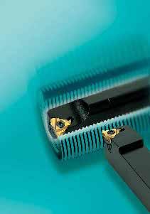
198 196
199 Gewindedrehen Thread Turning Wendeschneidplatten 198 Indexable inserts Teilprofil Partial profile A, AG, G, N: 55, A, AG, G, N: 55, 60 Vollprofil Full profile ISO-Metrisch 200 ISO Metric BSW, BSP 202 BSW, BSP Amerikanisch UN 206 American UN BSPT, American BUTTRESS 210 BSPT, American BUTTRESS Amerikanisch ACME, Stub ACME 212 American ACME, Stub ACME NPT, NPTF 214 NPT, NPTF Rund DIN 405, Trapez DIN Round DIN 405, Trapezoidal DIN 103 API 218 API Klemmhalter, Ersatzteile 220 Tool holders, spare parts Technische Hinweise Technical tips LMT-Schneidstoffsorten, Übersicht 221 LMT-Turning grades, overview Arbeitsmethoden beim Gewindedrehen 222 Thread turning methods Flankenfreiwinkel 222 Flank clearence angle Zustellungsmethoden 223 Infeed methods Wahl der richtigen Unterlagsplatten 223 Choosing the correct anvil Steigungswinkel 224 Helix angle Unterlagsplatten 224 Anvils Bearbeitungsbeispiele 225 Machining examples Anzahl der Durchgänge 226 Number of passes Maßnahmen bei Bearbeitungsproblemen, Gewindedrehen 226 Options against machining problems, thread turning Schnittdatenrichtwerte, Gewindedrehen 227 Cutting data standard values, thread turning 197
200 Wendeschneidplatten - Außengewinde Indexable Inserts - External Threads Mutter Nut 60 Teilprofil 60 Partial Profile 60 l x y Rechts Right hand r d Schraube Bolt s Bestellbezeichnung Ordering Code Steigung Pitch mm Gang / Zoll tpi l d s r x y Sorte Grade Unterlage Anvil B16ERA60 0,5-1, ,52 3,97 0,05 0,8 0,9 BYE16 AL B16ERAG60 0,5-3, ,52 3,97 0,06 1,2 1,7 BYE16 B16ERG60 1,75-3, ,52 3,97 0,25 1,2 1,7 BYE16 B22ERN60 3,5-5, ,70 5,56 0,51 1,7 2,5 BYE22 AL LC220N LC620N Passendes Werkzeug Suitable toolholder Seite Page Links Left hand B16ELA60 0,5-1, ,52 3,97 0,05 0,8 0,9 BYI16 AL B16ELAG60 0,5-3, ,52 3,97 0,06 1,2 1,7 BYI16 B16ELG60 1,75-3, ,52 3,97 0,25 1,2 1,7 BYI16 B22ELN60 3,5-5, ,70 5,56 0,51 1,7 2,5 BYI22 AL Mutter Nut 55 Teilprofil 55 Partial Profile 55 l x y Rechts Right hand r d Schraube Bolt s Bestellbezeichnung Ordering Code Steigung Pitch mm Gang / Zoll tpi l d s r x y Sorte Grade Unterlage Anvil B16ERA55 0,5-1, ,52 3,97 0,05 0,8 0,9 BYE16 AL B16ERG55 1,75-3, ,52 3,97 0,20 1,2 1,7 BYE16 B16ERAG55 0,5-3, ,52 3,97 0,07 1,2 1,7 BYE16 B22ERN55 3,5-5, ,70 5,56 0,43 1,7 2,5 BYE22 AL LC220N LC620N Passendes Werkzeug Suitable toolholder Seite Page Links Left hand B16ELA55 0,5-1, ,52 3,97 0,05 0,8 0,9 BYI16 AL B16ELG55 1,75-3, ,52 3,97 0,20 1,2 1,7 BYI16 B16ELAG55 0,5-3, ,52 3,97 0,07 1,2 1,7 BYI16 B22ELN55 3,5-5, ,70 5,56 0,43 1,7 2,5 BYI22 AL Bestellbeispiel Order Example: 10 Stück off B16ERA60 LC220N Verfügbar ab Lager Auf Anfrage Available from stock Upon Request 198
201 Wendeschneidplatten - Innengewinde Indexable Inserts - Internal Threads Mutter Nut 60 Teilprofil 60 Partial Profile 60 x y Rechts Right hand r d l Schraube Bolt s Bestellbezeichnung Ordering Code Steigung Pitch mm Gang / Zoll tpi l d s r x y Sorte Grade Unterlage Anvil B11IRA60 0,5-1, ,35 3,17 0,05 0,8 0,9 - NVR B16IRA60 0,5-1, ,52 3,97 0,05 0,8 0,9 BYI16 AVR B16IRG60 1,75-3, ,52 3,97 0,15 1,2 1,7 BYI16 NVR B16IRAG60 0,5-3, ,52 3,97 0,05 1,2 1,7 BYI16 B22IRN60 3,5-5, ,70 5,56 0,28 1,7 2,5 BYI22 AVR NVR LC220N LC620N Passendes Werkzeug Suitable toolholder Seite Page Links Left hand B11ILA60 0,5-1, ,35 3,17 0,05 0,8 0,9 - NVR B16ILA60 0,5-1, ,52 3,97 0,05 0,8 0,9 BYE16 AVR B16ILG60 1,75-3, ,52 3,97 0,15 1,2 1,7 BYE16 NVR B16ILAG60 0,5-3, ,52 3,97 0,05 1,2 1,7 BYE16 B22ILN60 3,5-5, ,70 5,56 0,28 1,7 2,5 BYE22 AVR NVR Mutter Nut 55 Teilprofil 55 Partial Profile 55 x y Rechts Right hand r d l Schraube Bolt s Bestellbezeichnung Ordering Code Steigung Pitch mm Gang / Zoll tpi l d s r x y Sorte Grade Unterlage Anvil B11IRA55 0,5-1, ,35 3,17 0,05 0,8 0,9 - NVR B16IRA55 0,5-1, ,52 3,97 0,05 0,8 0,9 BYI16 AVR B16IRG55 1,75-3, ,52 3,97 0,20 1,2 1,7 BYI16 NVR B16IRAG55 0,5-3, ,52 3,97 0,07 1,2 1,7 BYI16 B22IRN55 3,5-5, ,70 5,56 0,43 1,7 2,5 BYI22 AVR NVR..-22 LC220N LC620N Passendes Werkzeug Suitable toolholder Seite Page Links Left hand B11ILA55 0,5-1, ,35 3,17 0,05 0,8 0,9 - NVR B16ILA55 0,5-1, ,52 3,97 0,05 0,8 0,9 BYE16 AVR B16ILG55 1,75-3, ,52 3,97 0,20 1,2 1,7 BYE16 NVR B16ILAG55 0,5-3, ,52 3,97 0,07 1,2 1,7 BYE16 B22ILN55 3,5-5, ,70 5,56 0,43 1,7 2,5 BYE22 AVR NVR..-22 Bestellbeispiel Order Example: 10 Stück off B11IRA60 LC220N Verfügbar ab Lager Auf Anfrage Available from stock Upon Request 199
202 Wendeschneidplatten - Außengewinde Indexable Inserts - External Threads Mutter Nut 1/4P 60 ISO-Metrisch Vollprofil ISO-Metric Full Profile h l x y d Rechts Right hand Links Left hand 1/8P Schraube Bolt s Bestellbezeichnung Ordering Code Steigung Pitch mm Gang / Zoll tpi l d s r x y Sorte Grade Unterlage Anvil B16ER0,5ISO 0,5-16 9,52 3,97-0,6 0,4 BYE16 AL B16ER0,75ISO 0, ,52 3,97-0,6 0,6 BYE16 B16ER1,0ISO ,52 3,97-0,7 0,7 BYE16 B16ER1,25ISO 1, ,52 3,97-0,8 0,9 BYE16 B16ER1,5ISO 1,5-16 9,52 3,97-0,8 1,0 BYE16 B16ER1,75ISO 1, ,52 3,97-0,9 1,2 BYE16 B16ER2,0ISO ,52 3,97-1,0 1,3 BYE16 B16ER2,5ISO 2,5-16 9,52 3,97-1,1 1,5 BYE16 B16ER3,0ISO ,52 3,97-1,2 1,6 BYE16 B22ER3,5ISO 3, ,70 5,56-1,6 2,3 BYE22 AL B22ER4,0ISO ,70 5,56-1,6 2,3 BYE22 B22ER4,5ISO 4, ,70 5,56-1,7 2,4 BYE22 B22ER5,0ISO ,70 5,56-1,7 2,5 BYE22 B16EL0,5ISO 0,5-16 9,52 3,97-0,6 0,4 BYI16 AL B16EL0,75ISO 0, ,52 3,97-0,6 0,6 BYI16 B16EL1,0ISO ,52 3,97-0,7 0,7 BYI16 B16EL1,25ISO 1, ,52 3,97-0,8 0,9 BYI16 B16EL1,5ISO 1,5-16 9,52 3,97-0,8 1,0 BYI16 B16EL1,75ISO 1, ,52 3,97-0,9 1,2 BYI16 B16EL2,0ISO ,52 3,97-1,0 1,3 BYI16 B16EL2,5ISO 2,5-16 9,52 3,97-1,1 1,5 BYI16 B16EL3,0ISO ,52 3,97-1,2 1,6 BYI16 B22EL3,5ISO 3, ,70 5,56-1,6 2,3 BYI22 AL B22EL4,0ISO ,70 5,56-1,6 2,3 BYI22 B22EL4,5ISO 4, ,70 5,56-1,7 2,4 BYI22 B22EL5,0ISO ,70 5,56-1,7 2,5 BYI22 LC220N LC620N Passendes Werkzeug Suitable toolholder Seite Page Bestellbeispiel Order Example: 10 Stück off B16ER0, 5ISO LC220N Verfügbar ab Lager Auf Anfrage Available from stock Upon Request 200
203 Wendeschneidplatten - Innengewinde Indexable Inserts - Internal Threads Mutter Nut 1/4P 60 ISO-Metrisch Vollprofil ISO-Metric Full Profile h x y d Rechts Right hand Links Left hand l 1/8P Schraube Bolt s Bestellbezeichnung Ordering Code Steigung Pitch mm Gang / Zoll tpi l d s r x y Sorte Grade Unterlage Anvil B11IR0,5ISO 0,5-11 6,35 3,17-0,6 0,4 - NVR B11IR0,75ISO 0, ,35 3,17-0,6 0,6 - B11IR1,0ISO 1,0-11 6,35 3,17-0,6 0,7 - B11IR1,25ISO 1, ,35 3,17-0,8 0,9 - B11IR1,5ISO 1,5-11 6,35 3,17-0,8 1,0 - B11IR1,75ISO 1, ,35 3,17-0,9 1,1 - B11IR2,0ISO 2,0-11 6,35 3,17-0,9 1,1 - B16IR0,5ISO 0,5-16 9,52 3,97-0,6 0,4 BYI16 AVR B16IR0,75ISO 0, ,52 3,97-0,6 0,6 BYI16 NVR B16IR1,0ISO 1,0-16 9,52 3,97-0,6 0,7 BYI16 B16IR1,25ISO 1, ,52 3,97-0,8 0,9 BYI16 B16IR1,5ISO 1,5-16 9,52 3,97-0,8 1,0 BYI16 B16IR1,75ISO 1, ,52 3,97-0,9 1,2 BYI16 B16IR2,0ISO 2,0-16 9,52 3,97-1,0 1,3 BYI16 B16IR2,5ISO 2,5-16 9,52 3,97-1,1 1,5 BYI16 B16IR3,0ISO 3,0-16 9,52 3,97-1,1 1,5 BYI16 B22IR3,5ISO 3, ,70 5,56-1,6 2,3 BYI22 AVR B22IR4,0ISO 4, ,70 5,56-1,6 2,3 BYI22 NVR B22IR4,5ISO 4, ,70 5,56-1,6 2,4 BYI22 B22IR5,0ISO 5, ,70 5,56-1,6 2,3 BYI22 B11IL0,5ISO 0,5-11 6,35 3,17-0,6 0,4 - NVR B11IL0,75ISO 0, ,35 3,17-0,6 0,6 - B11IL1,0ISO 1,0-11 6,35 3,17-0,6 0,7 - B11IL1,25ISO 1, ,35 3,17-0,8 0,9 - B11IL1,5ISO 1,5-11 6,35 3,17-0,8 1,0 - B11IL1,75ISO 1, ,35 3,17-0,9 1,1 - B11IL2,0ISO 2,0-11 6,35 3,17-0,9 1,1 - B16IL0,5ISO 0,5-16 9,52 3,97-0,6 0,4 BYE16 AVR B16IL0,75ISO 0, ,52 3,97-0,6 0,6 BYE16 NVR B16IL1,0ISO 1,0-16 9,52 3,97-0,6 0,7 BYE16 B16IL1,25ISO 1, ,52 3,97-0,8 0,9 BYE16 B16IL1,5ISO 1,5-16 9,52 3,97-0,8 1,0 BYE16 B16IL1,75ISO 1, ,52 3,97-0,9 1,2 BYE16 B16IL2,0ISO 2,0-16 9,52 3,97-1,0 1,3 BYE16 B16IL2,5ISO 2,5-16 9,52 3,97-1,1 1,5 BYE16 B16IL3,0ISO 3,0-16 9,52 3,97-1,1 1,5 BYE16 B22IL3,5ISO 3, ,70 5,56-1,6 2,3 BYE22 AVR B22IL4,0ISO 4, ,70 5,56-1,6 2,3 BYE22 NVR B22IL4,5ISO 4, ,70 5,56-1,6 2,4 BYE22 B22IL5,0ISO 5, ,70 5,56-1,6 2,3 BYE22 LC220N LC620N Passendes Werkzeug Suitable toolholder Seite Page Bestellbeispiel Order Example: 10 Stück off B11IR0, 5ISO LC220N Verfügbar ab Lager Auf Anfrage Available from stock Upon Request 201
204 Wendeschneidplatten - Außengewinde Indexable Inserts - External Threads Mutter Nut R=0,137P 55 BSW, BSP Vollprofil BSW, BSP Full Profile l x y R=0,137P d Rechts Right hand Schraube Bolt s Bestellbezeichnung Ordering Code Steigung Pitch mm Gang / Zoll tpi l d s r x y Sorte Grade Unterlage Anvil B16ER8W ,52 3,97-1,2 1,5 BYE16 AL B16ER9W ,52 3,97-1,2 1,7 BYE16 B16ER10W ,52 3,97-1,1 1,5 BYE16 B16ER11W ,52 3,97-1,1 1,5 BYE16 B16ER12W ,52 3,97-1,1 1,4 BYE16 B16ER14W ,52 3,97-1,0 1,2 BYE16 B16ER16W ,52 3,97-0,9 1,1 BYE16 B16ER18W ,52 3,97-0,8 1,0 BYE16 B16ER19W ,52 3,97-0,8 1,0 BYE16 B16ER20W ,52 3,97-0,8 0,9 BYE16 B16ER22W ,52 3,97-0,8 0,9 BYE16 B16ER24W ,52 3,97-0,7 0,8 BYE16 B16ER26W ,52 3,97-0,7 0,8 BYE16 B16ER28W ,52 3,97-0,6 0,7 BYE16 B16ER32W ,52 3,97-0,6 0,6 BYE16 B16ER36W ,52 3,97-0,6 0,6 BYE16 B16ER40W ,52 3,97-0,6 0,6 BYE16 B16ER48W ,52 3,97-0,6 0,6 BYE16 B16ER56W ,52 3,97-0,7 0,4 BYE16 B22ER5W ,70 5,56-1,7 2,4 BYE22 AL B22ER6W ,70 5,56-1,6 2,3 BYE22 B22ER7W ,70 5,56-1,6 2,3 BYE22 LC220N LC620N Passendes Werkzeug Suitable toolholder Seite Page Bestellbeispiel Order Example: 10 Stück off B16ER8W LC220N Verfügbar ab Lager Auf Anfrage Available from stock Upon Request 202
205 Wendeschneidplatten - Innengewinde Indexable Inserts - Internal Threads Mutter Nut R=0,137P 55 BSW, BSP Vollprofil BSW, BSP Full Profile x y R=0,137P d Rechts Right hand l Schraube Bolt s Bestellbezeichnung Ordering Code Steigung Pitch mm Gang / Zoll tpi l d s r x y Sorte Grade Unterlage Anvil B11IR14W ,35 3,17-0,9 1,1 - NVR B11IR16W ,35 3,17-0,9 1,1 - B11IR18W ,35 3,17-0,8 1,0 - B11IR19W ,35 3,17-0,8 1,0 - B11IR20W ,35 3,17-0,8 0,9 - B11IR22W ,35 3,17-0,8 0,9 - B11IR24W ,35 3,17-0,7 0,8 - B11IR26W ,35 3,17-0,7 0,8 - B11IR28W ,35 3,17-0,6 0,7 - B11IR32W ,35 3,17-0,6 0,6 - B11IR36W ,35 3,17-0,6 0,6 - B11IR40W ,35 3,17-0,6 0,6 - B11IR48W ,35 3,17-0,6 0,6 - B11IR56W ,35 3,17-0,7 0,4 - B16IR8W ,52 3,97-1,2 1,5 BYI16 AVR B16IR9W ,52 3,97-1,2 1,7 BYI16 NVR B16IR10W ,52 3,97-1,1 1,5 BYI16 B16IR11W ,52 3,97-1,1 1,5 BYI16 B16IR12W ,52 3,97-1,1 1,4 BYI16 B16IR14W ,52 3,97-1,0 1,2 BYI16 B16IR16W ,52 3,97-0,9 1,1 BYI16 B16IR18W ,52 3,97-0,8 1,0 BYI16 B16IR19W ,52 3,97-0,8 1,0 BYI16 B16IR20W ,52 3,97-0,8 0,9 BYI16 B16IR22W ,52 3,97-0,8 0,9 BYI16 B16IR24W ,52 3,97-0,7 0,8 BYI16 B16IR26W ,52 3,97-0,7 0,8 BYI16 B16IR28W ,52 3,97-0,6 0,7 BYI16 B16IR32W ,52 3,97-0,6 0,6 BYI16 B16IR36W ,52 3,97-0,6 0,6 BYI16 B16IR40W ,52 3,97-0,6 0,6 BYI16 B16IR48W ,52 3,97-0,6 0,6 BYI16 B16IR56W ,52 3,97-0,7 0,4 BYI16 B22IR5W ,70 5,56-1,7 2,4 BYI22 AVR B22IR6W ,70 5,56-1,6 2,3 BYI22 NVR B22IR7W ,70 5,56-1,6 2,3 BYI22 LC220N LC620N Passendes Werkzeug Suitable toolholder Seite Page Bestellbeispiel Order Example: 10 Stück off B11IR14W LC220N Verfügbar ab Lager Auf Anfrage Available from stock Upon Request 203
206 Wendeschneidplatten - Außengewinde Indexable Inserts - External Threads Mutter Nut R=0,137P 55 BSW, BSP Vollprofil BSW, BSP Full Profile d y Links Left hand R=0,137P x l Schraube Bolt s Bestellbezeichnung Ordering Code Steigung Pitch mm Gang / Zoll tpi l d s r x y Sorte Grade Unterlage Anvil B16EL8W ,52 3,97-1,2 1,5 BYI16 AL B16EL9W ,52 3,97-1,2 1,7 BYI16 B16EL10W ,52 3,97-1,1 1,5 BYI16 B16EL11W ,52 3,97-1,1 1,5 BYI16 B16EL12W ,52 3,97-1,1 1,4 BYI16 B16EL14W ,52 3,97-1,0 1,2 BYI16 B16EL16W ,52 3,97-0,9 1,1 BYI16 B16EL18W ,52 3,97-0,8 1,0 BYI16 B16EL19W ,52 3,97-0,8 1,0 BYI16 B16EL20W ,52 3,97-0,8 0,9 BYI16 B16EL22W ,52 3,97-0,8 0,9 BYI16 B16EL24W ,52 3,97-0,7 0,8 BYI16 B16EL26W ,52 3,97-0,7 0,8 BYI16 B16EL28W ,52 3,97-0,6 0,7 BYI16 B16EL32W ,52 3,97-0,6 0,6 BYI16 B16EL36W ,52 3,97-0,6 0,6 BYI16 B16EL40W ,52 3,97-0,6 0,6 BYI16 B16EL48W ,52 3,97-0,6 0,6 BYI16 B16EL56W ,52 3,97-0,7 0,4 BYI16 B22EL5W ,70 5,56-1,7 2,4 BYI22 AL B22EL6W ,70 5,56-1,6 2,3 BYI22 B22EL7W ,70 5,56-1,6 2,3 BYI22 LC220N LC620N Passendes Werkzeug Suitable toolholder Seite Page Bestellbeispiel Order Example: 10 Stück off B16EL8W LC220N Verfügbar ab Lager Auf Anfrage Available from stock Upon Request 204
207 Wendeschneidplatten - Innengewinde Indexable Inserts - Internal Threads Mutter Nut R=0,137P 55 BSW, BSP Vollprofil BSW, BSP Full Profile x y d l Links Left hand R=0,137P Schraube Bolt s Bestellbezeichnung Ordering Code Steigung Pitch mm Gang / Zoll tpi l d s r x y Sorte Grade Unterlage Anvil B11IL14W ,35 3,17-0,9 1,1 - NVR B11IL16W ,35 3,17-0,9 1,1 - B11IL18W ,35 3,17-0,8 1,0 - B11IL19W ,35 3,17-0,8 1,0 - B11IL20W ,35 3,17-0,8 0,9 - B11IL22W ,35 3,17-0,8 0,9 - B11IL24W ,35 3,17-0,7 0,8 - B11IL26W ,35 3,17-0,7 0,8 - B11IL28W ,35 3,17-0,6 0,7 - B11IL32W ,35 3,17-0,6 0,6 - B11IL36W ,35 3,17-0,6 0,6 - B11IL40W ,35 3,17-0,6 0,6 - B11IL48W ,35 3,17-0,6 0,6 - B11IL56W ,35 3,17-0,7 0,4 - B16IL8W ,52 3,97-1,2 1,5 BYE16 AVR B16IL9W ,52 3,97-1,2 1,7 BYE16 NVR B16IL10W ,52 3,97-1,1 1,5 BYE16 B16IL11W ,52 3,97-1,1 1,5 BYE16 B16IL12W ,52 3,97-1,1 1,4 BYE16 B16IL14W ,52 3,97-1,0 1,2 BYE16 B16IL16W ,52 3,97-0,9 1,1 BYE16 B16IL18W ,52 3,97-0,8 1,0 BYE16 B16IL19W ,52 3,97-0,8 1,0 BYE16 B16IL20W ,52 3,97-0,8 0,9 BYE16 B16IL22W ,52 3,97-0,8 0,9 BYE16 B16IL24W ,52 3,97-0,7 0,8 BYE16 B16IL26W ,52 3,97-0,7 0,8 BYE16 B16IL28W ,52 3,97-0,6 0,7 BYE16 B16IL32W ,52 3,97-0,6 0,6 BYE16 B16IL36W ,52 3,97-0,6 0,6 BYE16 B16IL40W ,52 3,97-0,6 0,6 BYE16 B16IL48W ,52 3,97-0,6 0,6 BYE16 B16IL56W ,52 3,97-0,7 0,4 BYE16 B22IL5W ,70 5,56-1,7 2,4 BYE22 AVR B22IL6W ,70 5,56-1,6 2,3 BYE22 NVR B22IL7W ,70 5,56-1,6 2,3 BYE22 LC220N LC620N Passendes Werkzeug Suitable toolholder Seite Page Bestellbeispiel Order Example: 10 Stück off B11IL14W LC220N Verfügbar ab Lager Auf Anfrage Available from stock Upon Request 205
208 Wendeschneidplatten - Außengewinde Indexable Inserts - External Threads Mutter Nut 1/4P 60 Amerikanisch UN Vollprofil American UN Full Profile h l x y d Rechts Right hand 1/8P Schraube Bolt s Bestellbezeichnung Ordering Code Steigung Pitch mm Gang / Zoll tpi l d s r x y Sorte Grade Unterlage Anvil B16ER8UN ,52 3,97-1,2 1,6 BYE16 AL B16ER9UN ,52 3,97-1,2 1,7 BYE16 B16ER10UN ,52 3,97-1,1 1,5 BYE16 B16ER11UN ,52 3,97-1,1 1,5 BYE16 B16ER11,5UN - 11,5 16 9,52 3,97-1,1 1,5 BYE16 B16ER12UN ,52 3,97-1,1 1,4 BYE16 B16ER13UN ,52 3,97-1,0 1,3 BYE16 B16ER14UN ,52 3,97-1,0 1,2 BYE16 B16ER16UN ,52 3,97-0,9 1,1 BYE16 B16ER18UN ,52 3,97-0,8 1,0 BYE16 B16ER20UN ,52 3,97-0,8 0,9 BYE16 B16ER24UN ,52 3,97-0,7 0,8 BYE16 B16ER27UN ,52 3,97-0,7 0,8 BYE16 B16ER28UN ,52 3,97-0,6 0,7 BYE16 B16ER32UN ,52 3,97-0,6 0,6 BYE16 B16ER36UN ,52 3,97-0,6 0,6 BYE16 B16ER40UN ,52 3,97-0,6 0,6 BYE16 B16ER44UN ,52 3,97-0,6 0,6 BYE16 B16ER48UN ,52 3,97-0,6 0,6 BYE16 B16ER56UN ,52 3,97-0,7 0,4 BYE16 B16ER64UN ,52 3,97-0,8 0,4 BYE16 B16ER72UN ,52 3,97-0,8 0,4 BYE16 B22ER5UN ,70 5,56-1,7 2,5 BYE22 AL B22ER6UN ,70 5,56-1,6 2,3 BYE22 B22ER7UN ,70 5,56-1,6 2,3 BYE22 LC220N LC620N Passendes Werkzeug Suitable toolholder Seite Page Bestellbeispiel Order Example: 10 Stück off B16ER8UN LC220N Verfügbar ab Lager Auf Anfrage Available from stock Upon Request 206
209 Wendeschneidplatten - Innengewinde Indexable Inserts - Internal Threads Mutter Nut 1/4P 60 Amerikanisch UN Vollprofil American UN Full Profile h x y d Rechts Right hand l 1/8P Schraube Bolt s Bestellbezeichnung Ordering Code Steigung Pitch mm Gang / Zoll tpi l d s r x y Sorte Grade Unterlage Anvil B11IR14UN ,35 3,17-0,9 1,1 - NVR B11IR16UN ,35 3,17-0,9 1,1 - B11IR18UN ,35 3,17-0,8 1,0 - B11IR20UN ,35 3,17-0,8 0,9 - B11IR24UN ,35 3,17-0,7 0,8 - B11IR27UN ,35 3,17-0,7 0,8 - B11IR28UN ,35 3,17-0,6 0,7 - B11IR32UN ,35 3,17-0,6 0,6 - B11IR36UN ,35 3,17-0,6 0,6 - B11IR40UN ,35 3,17-0,6 0,6 - B11IR44UN ,35 3,17-0,6 0,6 - B11IR48UN ,35 3,17-0,6 0,6 - B11IR56UN ,35 3,17-0,7 0,4 - B11IR64UN ,35 3,17-0,8 0,4 - B11IR72UN ,35 3,17-0,8 0,3 - B16IR8UN ,52 3,97-1,1 1,5 BYI16 AVR B16IR9UN ,52 3,97-1,2 1,7 BYI16 NVR B16IR10UN ,52 3,97-1,1 1,5 BYI16 B16IR11UN ,52 3,97-1,1 1,5 BYI16 B16IR11,5UN - 11,5 16 9,52 3,97-1,1 1,5 BYI16 B16IR12UN ,52 3,97-1,1 1,4 BYI16 B16IR13UN ,52 3,97-1,0 1,3 BYI16 B16IR14UN ,52 3,97-0,9 1,2 BYI16 B16IR16UN ,52 3,97-0,9 1,1 BYI16 B16IR18UN ,52 3,97-0,8 1,0 BYI16 B16IR20UN ,52 3,97-0,8 0,9 BYI16 B16IR24UN ,52 3,97-0,7 0,8 BYI16 B16IR27UN ,52 3,97-0,7 0,8 BYI16 B16IR28UN ,52 3,97-0,6 0,7 BYI16 B16IR32UN ,52 3,97-0,6 0,6 BYI16 B16IR36UN ,52 3,97-0,6 0,6 BYI16 B16IR40UN ,52 3,97-0,6 0,6 BYI16 B16IR44UN ,52 3,97-0,6 0,6 BYI16 B16IR48UN ,52 3,97-0,6 0,6 BYI16 B16IR56UN ,52 3,97-0,7 0,4 BYI16 B16IR64UN ,52 3,97-0,8 0,4 BYI16 B16IR72UN ,52 3,97-0,8 0,3 BYI16 B22IR5UN ,70 5,56-1,6 2,3 BYI22 AVR B22IR6UN ,70 5,56-1,6 2,3 BYI22 NVR B22IR7UN ,70 5,56-1,6 2,3 BYI22 LC220N LC620N Passendes Werkzeug Suitable toolholder Seite Page Bestellbeispiel Order Example: 10 Stück off B11IR14UN LC220N Verfügbar ab Lager Auf Anfrage Available from stock Upon Request 207
210 Wendeschneidplatten - Außengewinde Indexable Inserts - External Threads Mutter Nut 1/4P 60 Amerikanisch UN Vollprofil American UN Full Profile h d y Links Left hand 1/8P x l Schraube Bolt s Bestellbezeichnung Ordering Code Steigung Pitch mm Gang / Zoll tpi l d s r x y Sorte Grade Unterlage Anvil B16EL8UN ,52 3,97-1,2 1,6 BYI16 AL B16EL9UN ,52 3,97-1,2 1,7 BYI16 B16EL10UN ,52 3,97-1,1 1,5 BYI16 B16EL11UN ,52 3,97-1,1 1,5 BYI16 B16EL11,5UN - 11,5 16 9,52 3,97-1,1 1,5 BYI16 B16EL12UN ,52 3,97-1,1 1,4 BYI16 B16EL13UN ,52 3,97-1,0 1,3 BYI16 B16EL14UN ,52 3,97-1,0 1,2 BYI16 B16EL16UN ,52 3,97-0,9 1,1 BYI16 B16EL18UN ,52 3,97-0,8 1,0 BYI16 B16EL20UN ,52 3,97-0,8 0,9 BYI16 B16EL24UN ,52 3,97-0,7 0,8 BYI16 B16EL27UN ,52 3,97-0,7 0,8 BYI16 B16EL28UN ,52 3,97-0,6 0,7 BYI16 B16EL32UN ,52 3,97-0,6 0,6 BYI16 B16EL36UN ,52 3,97-0,6 0,6 BYI16 B16EL40UN ,52 3,97-0,6 0,6 BYI16 B16EL44UN ,52 3,97-0,6 0,6 BYI16 B16EL48UN ,52 3,97-0,6 0,6 BYI16 B16EL56UN ,52 3,97-0,7 0,4 BYI16 B16EL64UN ,52 3,97-0,8 0,4 BYI16 B16EL72UN ,52 3,97-0,8 0,4 BYI16 B22EL5UN ,70 5,56-1,7 2,5 BYI22 AL B22EL6UN ,70 5,56-1,6 2,3 BYI22 B22EL7UN ,70 5,56-1,6 2,3 BYI22 LC220N LC620N Passendes Werkzeug Suitable toolholder Seite Page Bestellbeispiel Order Example: 10 Stück off B16EL8UN LC220N Verfügbar ab Lager Auf Anfrage Available from stock Upon Request 208
211 Wendeschneidplatten - Innengewinde Indexable Inserts - Internal Threads Mutter Nut 1/4P 60 Amerikanisch UN Vollprofil American UN Full Profile h x y d l Links Left hand 1/8P Schraube Bolt s Bestellbezeichnung Ordering Code Steigung Pitch mm Gang / Zoll tpi l d s r x y Sorte Grade Unterlage Anvil B11IL14UN ,35 3,17-0,9 1,1 - NVR B11IL16UN ,35 3,17-0,9 1,1 - B11IL18UN ,35 3,17-0,8 1,0 - B11IL20UN ,35 3,17-0,8 0,9 - B11IL24UN ,35 3,17-0,7 0,8 - B11IL27UN ,35 3,17-0,7 0,8 - B11IL28UN ,35 3,17-0,6 0,7 - B11IL32UN ,35 3,17-0,6 0,6 - B11IL36UN ,35 3,17-0,6 0,6 - B11IL40UN ,35 3,17-0,6 0,6 - B11IL44UN ,35 3,17-0,6 0,6 - B11IL48UN ,35 3,17-0,6 0,6 - B11IL56UN ,35 3,17-0,7 0,4 - B11IL64UN ,35 3,17-0,8 0,4 - B11IL72UN ,35 3,17-0,8 0,3 - B16IL8UN ,52 3,97-1,1 1,5 BYE16 AVR B16IL9UN ,52 3,97-1,2 1,7 BYE16 NVR B16IL10UN ,52 3,97-1,1 1,5 BYE16 B16IL11UN ,52 3,97-1,1 1,5 BYE16 B16IL11,5UN - 11,5 16 9,52 3,97-1,1 1,5 BYE16 B16IL12UN ,52 3,97-1,1 1,4 BYE16 B16IL13UN ,52 3,97-1,0 1,3 BYE16 B16IL14UN ,52 3,97-0,9 1,2 BYE16 B16IL16UN ,52 3,97-0,9 1,1 BYE16 B16IL18UN ,52 3,97-0,8 1,0 BYE16 B16IL20UN ,52 3,97-0,8 0,9 BYE16 B16IL24UN ,52 3,97-0,7 0,8 BYE16 B16IL27UN ,52 3,97-0,7 0,8 BYE16 B16IL28UN ,52 3,97-0,6 0,7 BYE16 B16IL32UN ,52 3,97-0,6 0,6 BYE16 B16IL36UN ,52 3,97-0,6 0,6 BYE16 B16IL40UN ,52 3,97-0,6 0,6 BYE16 B16IL44UN ,52 3,97-0,6 0,6 BYE16 B16IL48UN ,52 3,97-0,6 0,6 BYE16 B16IL56UN ,52 3,97-0,7 0,4 BYE16 B16IL64UN ,52 3,97-0,8 0,4 BYE16 B16IL72UN ,52 3,97-0,8 0,3 BYE16 B22IL5UN ,70 5,56-1,6 2,3 BYE22 AVR B22IL6UN ,70 5,56-1,6 2,3 BYE22 NVR B22IL7UN ,70 5,56-1,6 2,3 BYE22 LC220N LC620N Passendes Werkzeug Suitable toolholder Seite Page Bestellbeispiel Order Example: 10 Stück off B11IL14UN LC220N Verfügbar ab Lager Auf Anfrage Available from stock Upon Request 209
212 Wendeschneidplatten - Außengewinde Indexable Inserts - External Threads Mutter R=0,137P Nut 27,5 27,5 BSPT - Vollprofil BSPT - Full Profile l 90 x y d Rechts Right hand 1 47' Schraube Bolt s Bestellbezeichnung Ordering Code Steigung Pitch mm Gang / Zoll tpi l d s r x y Sorte Grade Unterlage Anvil B16ER11BSPT ,52 3,97-1,1 1,5 BYE16 AL B16ER14BSPT ,52 3,97-1,0 1,2 BYE16 B16ER19BSPT ,52 3,97-0,8 0,9 BYE16 B16ER28BSPT ,52 3,97-0,6 0,6 BYE16 LC220N LC620N Passendes Werkzeug Suitable toolholder Seite Page Links Left hand B16EL11BSPT ,52 3,97-1,1 1,5 BYI16 AL B16EL14BSPT ,52 3,97-1,0 1,2 BYI16 B16EL19BSPT ,52 3,97-0,8 0,9 BYI16 B16EL28BSPT ,52 3,97-0,6 0,6 BYI16 Mutter Nut 0,16316P 45 7 American Buttress - Vollprofil American Buttress - Full Profile l x y 0,16316P d Rechts Right hand Schraube Bolt s Bestellbezeichnung Ordering Code Steigung Pitch mm Gang / Zoll tpi l d s r x y Sorte Grade Unterlage Anvil B16ER10ABUT ,52 3,97-1,5 2,3 BYE16 AL B16ER12ABUT ,52 3,97-1,4 2,0 BYE16 B16ER16ABUT ,52 3,97-1,3 1,9 BYE16 B16ER20ABUT ,52 3,97-1,0 1,4 BYE16 B22ER6ABUT ,70 5,56-2,2 3,5 BYE22 AL B22ER8ABUT ,70 5,56-2,0 3,2 BYE22 LC220N LC620N Passendes Werkzeug Suitable toolholder Seite Page Links Left hand B16EL10ABUT ,52 3,97-1,5 2,3 BYI16 AL B16EL12ABUT ,52 3,97-1,4 2,0 BYI16 B16EL16ABUT ,52 3,97-1,3 1,9 BYI16 B16EL20ABUT ,52 3,97-1,0 1,4 BYI16 B22EL6ABUT ,70 5,56-2,2 3,5 BYI22 AL B22EL8ABUT ,70 5,56-2,0 3,2 BYI22 Bestellbeispiel Order Example: 10 Stück off B16ER11BSPT LC220N Verfügbar ab Lager Auf Anfrage Available from stock Upon Request 210
213 Wendeschneidplatten - Innengewinde Indexable Inserts - Internal Threads Mutter R=0,137P Nut 27,5 27,5 BSPT - Vollprofil BSPT - Full Profile 90 y d Rechts Right hand Links Left hand l x 1 47' Schraube Bolt s Bestellbezeichnung Ordering Code Steigung Pitch mm Gang / Zoll tpi l d s r x y Sorte Grade Unterlage Anvil B11IR14BSPT ,35 3,17-0,9 1,0 - NVR B11IR19BSPT ,35 3,17-0,8 0,9 - B11IR28BSPT ,35 3,17-0,6 0,6 - B16IR11BSPT ,52 3,97-1,1 1,5 BYI16 AVR B16IR14BSPT ,52 3,97-1,0 1,2 BYI16 NVR B16IR19BSPT ,52 3,97-0,8 0,9 BYI16 B16IR28BSPT ,52 3,97-0,6 0,6 BYI16 B11IL14BSPT ,35 3,17-0,9 1,0 - NVR B11IL19BSPT ,35 3,17-0,8 0,9 - B11IL28BSPT ,35 3,17-0,6 0,6 - B16IL11BSPT ,52 3,97-1,1 1,5 BYE16 AVR B16IL14BSPT ,52 3,97-1,0 1,2 BYE16 NVR B16IL19BSPT ,52 3,97-0,8 0,9 BYE16 B16IL28BSPT ,52 3,97-0,6 0,6 BYE16 LC220N LC620N Passendes Werkzeug Suitable toolholder Seite Page Mutter Nut 0,16316P 45 7 American Buttress - Vollprofil American Buttress - Full Profile x y 0,16316P d Rechts Right hand Links Left hand l Schraube Bolt s Bestellbezeichnung Ordering Code Steigung Pitch mm Gang / Zoll tpi l d s r x y Sorte Grade Unterlage Anvil B11IR16ABUT ,35 3,17-1,3 1,9 - NVR B11IR20ABUT ,35 3,17-1,0 1,4 - B16IR10ABUT ,52 3,97-1,5 2,3 BYI16 AVR B16IR12ABUT ,52 3,97-1,4 2,0 BYI16 NVR B16IR16ABUT ,52 3,97-1,3 1,9 BYI16 B16IR20ABUT ,52 3,97-1,0 1,4 BYI16 B22IR6ABUT ,70 5,56-2,2 3,5 BYI22 AVR B22IR8ABUT ,70 5,56-2,0 3,2 BYI22 NVR B11IL16ABUT ,35 3,17-1,3 1,9 - NVR B11IL20ABUT ,35 3,17-1,0 1,4 - B16IL10ABUT ,52 3,97-1,5 2,3 BYE16 AVR B16IL12ABUT ,52 3,97-1,4 2,0 BYE16 NVR B16IL16ABUT ,52 3,97-1,3 1,9 BYE16 B16IL20ABUT ,52 3,97-1,0 1,4 BYE16 B22IL6ABUT ,70 5,56-2,2 3,5 BYE22 AVR B22IL8ABUT ,70 5,56-2,0 3,2 BYE22 NVR LC220N LC620N Passendes Werkzeug Suitable toolholder Seite Page Bestellbeispiel Order Example: 10 Stück off B11IR14BSPT LC220N Verfügbar ab Lager Auf Anfrage Available from stock Upon Request 211
214 Wendeschneidplatten - Außengewinde Indexable Inserts - External Threads Mutter Nut 29 Amerikanisch ACME - Vollprofil American ACME - Full Profile l x y d Rechts Right hand Links Left hand Schraube Bolt s Bestellbezeichnung Ordering Code Steigung Pitch mm Gang / Zoll tpi l d s r x y Sorte Grade Unterlage Anvil B16ER8ACME ,52 3,97-1,4 1,5 BYE16 AL B16ER10ACME ,52 3,97-1,3 1,4 BYE16 B16ER12ACME ,52 3,97-1,1 1,2 BYE16 B16ER14ACME ,52 3,97-1,0 1,2 BYE16 B16ER16ACME ,52 3,97-1,0 1,1 BYE16 B22ER5ACME ,70 5,56-2,0 2,3 BYE22 AL B22ER6ACME ,70 5,56-1,8 2,1 BYE22 B16EL8ACME ,52 3,97-1,4 1,5 BYI16 AL B16EL10ACME ,52 3,97-1,3 1,4 BYI16 B16EL12ACME ,52 3,97-1,1 1,2 BYI16 B16EL14ACME ,52 3,97-1,0 1,2 BYI16 B16EL16ACME ,52 3,97-1,0 1,1 BYI16 B22EL5ACME ,70 5,56-2,0 2,3 BYI22 AL B22EL6ACME ,70 5,56-1,8 2,1 BYI22 LC220N LC620N Passendes Werkzeug Suitable toolholder Seite Page Mutter Nut 29 Stub ACME - Vollprofil Stub ACME - Full Profile l x y d Rechts Right hand Links Left hand Schraube Bolt s Bestellbezeichnung Ordering Code Steigung Pitch mm Gang / Zoll tpi l d s r x y Sorte Grade Unterlage Anvil B16ER6STACME ,52 3,97-1,7 1,8 BYE16 AL B16ER8STACME ,52 3,97-1,4 1,5 BYE16 B16ER10STACME ,52 3,97-1,2 1,3 BYE16 B16ER12STACME ,52 3,97-1,2 1,2 BYE16 B16ER14STACME ,52 3,97-1,1 1,1 BYE16 B16ER16STACME ,52 3,97-1,0 1,0 BYE16 B22ER5STACME ,70 5,56-2,1 2,3 BYE22 AL B16EL6STACME ,52 3,97-1,7 1,8 BYI16 AL B16EL8STACME ,52 3,97-1,4 1,5 BYI16 B16EL10STACME ,52 3,97-1,2 1,3 BYI16 B16EL12STACME ,52 3,97-1,2 1,2 BYI16 B16EL14STACME ,52 3,97-1,1 1,1 BYI16 B16EL16STACME ,52 3,97-1,0 1,0 BYI16 B22EL5STACME ,70 5,56-2,1 2,3 BYI22 AL LC220N LC620N Passendes Werkzeug Suitable toolholder Seite Page Bestellbeispiel Order Example: 10 Stück off B16ER8ACME LC220N Verfügbar ab Lager Auf Anfrage Available from stock Upon Request 212
215 Wendeschneidplatten - Innengewinde Indexable Inserts - Internal Threads Mutter Nut 29 Amerikanisch ACME - Vollprofil American ACME - Full Profile y Rechts Right hand Links Left hand l x d Schraube Bolt s Bestellbezeichnung Ordering Code Steigung Pitch mm Gang / Zoll tpi l d s r x y Sorte Grade Unterlage Anvil B11IR16ACME ,35 3,17-0,9 0,9 - NVR B16IR8ACME ,52 3,97-1,4 1,5 BYI16 AVR B16IR10ACME ,52 3,97-1,2 1,3 BYI16 NVR B16IR12ACME ,52 3,97-1,2 1,3 BYI16 B16IR14ACME ,52 3,97-1,1 1,2 BYI16 B16IR16ACME ,52 3,97-1,0 1,1 BYI16 B22IR5ACME ,70 5,56-2,0 2,3 BYI22 AVR B22IR6ACME ,70 5,56-1,8 2,1 BYI22 NVR B11IL16ACME ,35 3,17-0,9 0,9 - NVR B16IL8ACME ,52 3,97-1,4 1,5 BYE16 AVR B16IL10ACME ,52 3,97-1,2 1,3 BYE16 NVR B16IL12ACME ,52 3,97-1,2 1,3 BYE16 B16IL14ACME ,52 3,97-1,1 1,2 BYE16 B16IL16ACME ,52 3,97-1,0 1,1 BYE16 B22IL5ACME ,70 5,56-2,0 2,3 BYE22 AVR B22IL6ACME ,70 5,56-1,8 2,1 BYE22 NVR LC220N LC620N Passendes Werkzeug Suitable toolholder Seite Page Mutter Nut 29 Stub ACME - Vollprofil Stub ACME - Full Profile y Rechts Right hand Links Left hand l x d Schraube Bolt s Bestellbezeichnung Ordering Code Steigung Pitch mm Gang / Zoll tpi l d s r x y Sorte Grade Unterlage Anvil B11IR16STACME ,35 3,17-1,0 1,0 - NVR B16IR6STACME ,52 3,97-1,7 1,8 BYI16 AVR B16IR8STACME ,52 3,97-1,4 1,5 BYI16 NVR B16IR10STACME ,52 3,97-1,2 1,3 BYI16 B16IR12STACME ,52 3,97-1,1 1,2 BYI16 B16IR14STACME ,52 3,97-1,1 1,1 BYI16 B16IR16STACME ,52 3,97-1,0 1,0 BYI16 B22IR5STACME ,70 5,56-2,1 2,3 BYI22 AVR B11IL16STACME ,35 3,17-1,0 1,0 - NVR B16IL6STACME ,52 3,97-1,7 1,8 BYE16 AVR B16IL8STACME ,52 3,97-1,4 1,5 BYE16 NVR B16IL10STACME ,52 3,97-1,2 1,3 BYE16 B16IL12STACME ,52 3,97-1,1 1,2 BYE16 B16IL14STACME ,52 3,97-1,1 1,1 BYE16 B16IL16STACME ,52 3,97-1,0 1,0 BYE16 B22IL5STACME ,70 5,56-2,1 2,3 BYE22 AVR LC220N LC620N Passendes Werkzeug Suitable toolholder Seite Page Bestellbeispiel Order Example: 10 Stück off B11IR16ACME LC220N Verfügbar ab Lager Auf Anfrage Available from stock Upon Request 213
216 Wendeschneidplatten - Außengewinde Indexable Inserts - External Threads Mutter Nut NPT - Vollprofil NPT - Full Profile l 90 x y d 1 47' Rechts Right hand Schraube Bolt s Bestellbezeichnung Ordering Code Steigung Pitch mm Gang / Zoll tpi l d s r x y Sorte Grade Unterlage Anvil B16ER8NPT ,52 3,97-1,3 1,8 BYE16 AL B16ER11,5NPT - 11,5 16 9,52 3,97-1,1 1,5 BYE16 B16ER14NPT ,52 3,97-0,9 1,2 BYE16 B16ER18NPT ,52 3,97-0,8 1,0 BYE16 B16ER27NPT ,52 3,97-0,7 0,8 BYE16 LC220N LC620N Passendes Werkzeug Suitable toolholder Seite Page Links Left hand B16EL8NPT ,52 3,97-1,3 1,8 BYI16 AL B16EL11,5NPT - 11,5 16 9,52 3,97-1,1 1,5 BYI16 B16EL14NPT ,52 3,97-0,9 1,2 BYI16 B16EL18NPT ,52 3,97-0,8 1,0 BYI16 B16EL27NPT ,52 3,97-0,7 0,8 BYI16 Mutter Nut NPTF - Vollprofil NPTF - Full Profile l 90 x y 1 47' d Rechts Right hand Schraube Bolt s Bestellbezeichnung Ordering Code Steigung Pitch mm Gang / Zoll tpi l d s r x y Sorte Grade Unterlage Anvil B16ER8NPTF ,52 3,97-1,3 1,8 BYE16 AL B16ER11,5NPTF - 11,5 16 9,52 3,97-1,1 1,5 BYE16 B16ER14NPTF ,52 3,97-0,9 1,2 BYE16 B16ER18NPTF ,52 3,97-0,8 1,0 BYE16 B16ER27NPTF ,52 3,97-0,7 0,8 BYE16 LC220N LC620N Passendes Werkzeug Suitable toolholder Seite Page Links Left hand B16EL8NPTF ,52 3,97-1,3 1,8 BYI16 AL B16EL11,5NPTF - 11,5 16 9,52 3,97-1,1 1,5 BYI16 B16EL14NPTF ,52 3,97-0,9 1,2 BYI16 B16EL18NPTF ,52 3,97-0,8 1,0 BYI16 B16EL27NPTF ,52 3,97-0,7 0,8 BYI16 Bestellbeispiel Order Example: 10 Stück off B16ER8NPT LC220N Verfügbar ab Lager Auf Anfrage Available from stock Upon Request 214
217 Wendeschneidplatten - Innengewinde Indexable Inserts - Internal Threads Mutter Nut NPT - Vollprofil NPT - Full Profile 90 y Rechts Right hand Links Left hand l x d 1 47' Schraube Bolt s Bestellbezeichnung Ordering Code Steigung Pitch mm Gang / Zoll tpi l d s r x y Sorte Grade Unterlage Anvil B11IR14NPT ,35 3,17-0,8 1,0 - NVR B11IR18NPT ,35 3,17-0,8 1,0 - B11IR27NPT ,35 3,17-0,7 0,8 - B16IR8NPT ,52 3,97-1,3 1,8 BYI16 AVR B16IR11,5NPT - 11,5 16 9,52 3,97-1,1 1,5 BYI16 NVR B16IR14NPT ,52 3,97-0,9 1,2 BYI16 B16IR18NPT ,52 3,97-0,8 1,0 BYI16 B16IR27NPT ,52 3,97-0,7 0,8 BYI16 B11IL14NPT ,35 3,17-0,8 1,0 - NVR B11IL18NPT ,35 3,17-0,8 1,0 - B11IL27NPT ,35 3,17-0,7 0,8 - B16IL8NPT ,52 3,97-1,3 1,8 BYE16 AVR B16IL11,5NPT - 11,5 16 9,52 3,97-1,1 1,5 BYE16 NVR B16IL14NPT ,52 3,97-0,9 1,2 BYE16 B16IL18NPT ,52 3,97-0,8 1,0 BYE16 B16IL27NPT ,52 3,97-0,7 0,8 BYE16 LC220N LC620N Passendes Werkzeug Suitable toolholder Seite Page Mutter Nut NPTF - Vollprofil NPTF - Full Profile 90 y Rechts Right hand Links Left hand l x d 1 47' Schraube Bolt s Bestellbezeichnung Ordering Code Steigung Pitch mm Gang / Zoll tpi l d s r x y Sorte Grade Unterlage Anvil B11IR14NPTF ,35 3,17-0,8 1,0 - NVR B11IR18NPTF ,35 3,17-0,8 1,0 - B11IR27NPTF ,35 3,17-0,7 0,8 - B16IR8NPTF ,52 3,97-1,3 1,8 BYI16 AVR B16IR11,5NPTF - 11,5 16 9,52 3,97-1,1 1,5 BYI16 NVR B16IR14NPTF ,52 3,97-0,9 1,2 BYI16 B16IR18NPTF ,52 3,97-0,8 1,0 BYI16 B16IR27NPTF ,52 3,97-0,7 0,8 BYI16 B11IL14NPTF ,35 3,17-0,8 1,0 - NVR B11IL18NPTF ,35 3,17-0,8 1,0 - B11IL27NPTF ,35 3,17-0,7 0,8 - B16IL8NPTF ,52 3,97-1,3 1,8 BYE16 AVR B16IL11,5NPTF - 11,5 16 9,52 3,97-1,1 1,5 BYE16 NVR B16IL14NPTF ,52 3,97-0,9 1,2 BYE16 B16IL18NPTF ,52 3,97-0,8 1,0 BYE16 B16IL27NPTF ,52 3,97-0,7 0,8 BYE16 LC220N LC620N Passendes Werkzeug Suitable toolholder Seite Page Bestellbeispiel Order Example: 10 Stück off B11IR14NPT LC220N Verfügbar ab Lager Auf Anfrage Available from stock Upon Request 215
218 Wendeschneidplatten - Außengewinde Indexable Inserts - External Threads Mutter Nut 30 Rund DIN 405 Vollprofil Round DIN Full Profile l R=0,22105P x y d Rechts Right hand Schraube Bolt s Bestellbezeichnung Ordering Code Steigung Pitch mm Gang / Zoll tpi l d s r x y Sorte Grade Unterlage Anvil B16ER6RD ,52 3,97-1,5 1,7 BYE16 AL B16ER8RD ,52 3,97-1,4 1,3 BYE16 B16ER10RD ,52 3,97-1,1 1,2 BYE16 B22ER4RD ,70 5,56-2,2 2,3 BYE22 AL B22ER6RD ,70 5,56-1,5 1,7 BYE22 LC220N LC620N Passendes Werkzeug Suitable toolholder Seite Page Links Left hand B16EL6RD ,52 3,97-1,5 1,7 BYI16 AL B16EL8RD ,52 3,97-1,4 1,3 BYI16 B16EL10RD ,52 3,97-1,1 1,2 BYI16 B22EL4RD ,70 5,56-2,2 2,3 BYI22 AL B22EL6RD ,70 5,56-1,5 1,7 BYI22 Mutter Nut 30 Trapez DIN Vollprofil Trapezoidal DIN Full Profile h l x y d Rechts Right hand Schraube Bolt s Bestellbezeichnung Ordering Code Steigung Pitch mm Gang / Zoll tpi l d s r x y Sorte Grade Unterlage Anvil B16ER1,5TR 1,5-16 9,52 3,97-1,0 1,1 BYE16 AL B16ER2,0TR 2,0-16 9,52 3,97-1,1 1,3 BYE16 B16ER3,0TR 3,0-16 9,52 3,97-1,3 1,5 BYE16 B22ER4,0TR 4, ,70 5,56-1,7 1,9 BYE22 AL B22ER5,0TR 5, ,70 5,56-2,1 2,5 BYE22 LC220N LC620N Passendes Werkzeug Suitable toolholder Seite Page Links Left hand B16EL1,5TR 1,5-16 9,52 3,97-1,0 1,1 BYI16 AL B16EL2,0TR 2,0-16 9,52 3,97-1,1 1,3 BYI16 B16EL3,0TR 3,0-16 9,52 3,97-1,3 1,5 BYI16 B22EL4,0TR 4, ,70 5,56-1,7 1,9 BYI22 AL B22EL5,0TR 5, ,70 5,56-2,1 2,5 BYI22 Bestellbeispiel Order Example: 10 Stück off B16ER6RD LC220N Verfügbar ab Lager Auf Anfrage Available from stock Upon Request 216
219 Wendeschneidplatten - Innengewinde Indexable Inserts - Internal Threads Mutter Nut R=0,22105P 30 Rund DIN 405 Vollprofil Round DIN Full Profile y d Rechts Right hand l x Schraube Bolt s Bestellbezeichnung Ordering Code Steigung Pitch mm Gang / Zoll tpi l d s r x y Sorte Grade Unterlage Anvil B16IR6RD ,52 3,97-1,4 1,5 BYI16 AVR B16IR8RD ,52 3,97-1,4 1,4 BYI16 NVR B16IR10RD ,52 3,97-1,1 1,2 BYI16 B22IR4RD ,70 5,56-2,2 2,3 BYI22 AVR B22IR6RD ,70 5,56-1,5 1,7 BYI22 NVR LC220N LC620N Passendes Werkzeug Suitable toolholder Seite Page Links Left hand B16IL6RD ,52 3,97-1,4 1,5 BYE16 AVR B16IL8RD ,52 3,97-1,4 1,4 BYE16 NVR B16IL10RD ,52 3,97-1,1 1,2 BYE16 B22IL4RD ,70 5,56-2,2 2,3 BYE22 AVR B22IL6RD ,70 5,56-1,5 1,7 BYE22 NVR Mutter Nut 30 h Trapez DIN Vollprofil Trapezoidal DIN Full Profile y d Rechts Right hand l x Schraube Bolt s Bestellbezeichnung Ordering Code Steigung Pitch mm Gang / Zoll tpi l d s r x y Sorte Grade Unterlage Anvil B11IR1,5TR 1,5-11 6,35 3,17-0,8 0,9 - NVR B16IR1,5TR 1,5-16 9,52 3,97-1,0 1,1 BYI16 AVR B16IR2,0TR 2,0-16 9,52 3,97-1,1 1,3 BYI16 NVR B16IR3,0TR 3,0-16 9,52 3,97-1,3 1,5 BYI16 B22IR4,0TR 4, ,70 5,56-1,7 1,9 BYI22 AVR B22IR5,0TR 5, ,70 5,56-2,1 2,5 BYI22 NVR LC220N LC620N Passendes Werkzeug Suitable toolholder Seite Page Links Left hand B11IL1,5TR 1,5-11 6,35 3,17-0,8 0,9 - NVR B16IL1,5TR 1,5-16 9,52 3,97-1,0 1,1 BYE16 AVR B16IL2,0TR 2,0-16 9,52 3,97-1,1 1,3 BYE16 NVR B16IL3,0TR 3,0-16 9,52 3,97-1,3 1,5 BYE16 B22IL4,0TR 4, ,70 5,56-1,7 1,9 BYE22 AVR B22IL5,0TR 5, ,70 5,56-2,1 2,5 BYE22 NVR Bestellbeispiel Order Example: 10 Stück off B16IR6RD LC220N Verfügbar ab Lager Auf Anfrage Available from stock Upon Request 217
220 Wendeschneidplatten - Außengewinde Indexable Inserts - External Threads Mutter Nut API - Vollprofil API - Full Profile l 90 x y d Rechts Right hand Schraube Bolt s Bestellbezeichnung Ordering Code Steig. Gang / Zoll Pitch tpi Gewinde Thread Spitze Taper IPF Mutter-Nr. od.-größe Connection No. Or size l d s x y Sorte Grade Unterlage Anvil B22ER5API403 5 V-0, /8-4 1/ ,7 5,56 1,8 2,6 BYE22 AL REG B27ER4API382 4 V-0,038R 2 NC23-NC ,88 6,41 2,1 2,8 BYE27 AL OIL OIL B27ER4API383 4 V-0,038R 3 NC56-NC ,88 6,41 2,1 2,8 BYE27 AL OIL OIL B27ER4API502 4 V-0, /8 REG 27 15,88 6,41 2,1 3,1 BYE27 AL OIL OIL B27ER4API503 4 V-0, /2, 7 5/8, 27 15,88 6,41 2,1 3,1 BYE27 AL /8 REG OIL OIL LC220N LC620N Passendes Werkzeug Suitable toolholder Seite Page 218
221 Wendeschneidplatten - Innengewinde Indexable Inserts - Internal Threads Mutter Nut API - Vollprofil API - Full Profile 90 y d Rechts Right hand l x Schraube Bolt s Bestellbezeichnung Ordering Code Steig. Gang / Zoll Pitch tpi Gewinde Thread Spitze Taper IPF Mutter-Nr. od.-größe Connection No. Or size l d s x y Sorte Grade Unterlage Anvil B22IR5API403 5 V-0, /8-4 1/ ,7 5,56 1,8 2,6 BYI22 AVR REG B27IR4API382 4 V-0,038R 2 NC23-NC ,88 6,41 2,1 2,8 BYI27 AVR OIL OIL B27IR4API383 4 V-0,038R 3 NC56-NC ,88 6,41 2,1 2,8 BYI27 AVR OIL OIL B27IR4API502 4 V-0, /8 REG 27 15,88 6,41 2,1 3,1 BYI27 AVR OIL OIL B27IR4API503 4 V-0, /2, 7 5/8, 27 15,88 6,41 2,1 3,1 BYI27 AVR /8 REG OIL OIL LC220N LC620N Passendes Werkzeug Suitable toolholder Seite Page Bestellbeispiel Order Example: 10 Stück off B22ER5API403 LC220N Verfügbar ab Lager Auf Anfrage Available from stock Upon Request 219
222 Klemmhalter, Außenbearbeitung Toolholder, external machining 2 o b =h 2 =h 1 f l 1 l 2 Plattengröße Bestellbezeichnung h 1 Ordering Code Insert size f AL AL , AL , l 2 AL , AL , l 1 AL , AL32-27OIL , AL40-27OIL , h 2 b Klemmhalter, Innenbearbeitung Toolholder, internal machining l 1 l 2 A f d 1 d l 1 f Oil 4,5 o Bestellbezeichnung Ordering Code A l 1 l 2 d d 1 f D min Plattengröße Insert size NVR , ,0 7, NVR , ,0 8, NVR , ,7 10, NVR , ,0 11, NVR16D-16 15, ,0 11, AVR , ,0 13, AVR , ,0 16, AVR25D-16 22, ,6 16, AVR , ,0 19, AVR , ,0 23, NVR , ,0 15, AVR , ,0 17, AVR , ,0 21, AVR , ,0 25, AVR50-27OIL ,6 27 AVR80-27OIL ,7 27 Die Halter der Tabellen sind Rechtsausführung. Für Linksausführung bitte -LH an die Bezeichnung anfügen. Alle Halter haben einen 1,5 Steigungswinkel. Andere Steigungswinkel für AL.. und AVR..-Halter durch Wechsel der Unterlegplatte (siehe Seite 222). Halter NVR.. haben keine Unterlagsplatte. Innenhalter mit innerer Kühlmittelzufuhr auf Anfrage. The above holders are right hand execution. To obtain left hand execution, pls add LH to the ordering code. All holders have a 1,5 helix angle. Using AL.. and AVR..-holders helix angle can by varied by changing the anvil (please refer to page 222). NVR.. holders are without anvil. Holders with internal coolant supply on request. 220
223 Klemmhalter, Ersatzteile Toolholder, spare parts Klemmhalter Plattengröße Klemmschraube Schraube + Scheibe Schlüssel Unterlagsplatte Toolholder Insert size Clamp screw Screw + washer Key Anvil Bestellbezeichnung Ordering Code NVR 11 SN11T - V02-T NVR 16 SN16T - V02-T AL 16 SA16T SY16T V02-T-1000 BYE16 AL-LH 16 SA16T SY16T V02-T-1000 BYI16 AVR 16 SA16T SY16T V02-T-1000 BYI16 AVR-LH 16 SA16T SY16T V02-T-1000 BYE16 NVR 22 SN22T - V02-T-2000 AL 22 SA22T SY22T V02-T-2000 BYE22 AL-LH 22 SA22T SY22T V02-T-2000 BYI22 AVR 22 SA22T SY22T V02-T-2000 BYI22 AVR-LH 22 SA22T SY22T V02-T-2000 BYE22 AL-OIL 27 SA27T/C5 SY27T V02-T-2500 BYE27-OIL AL-OIL-LH 27 SA27T/C5 SY27T V02-T-2500 BYI27-OIL AVR-OIL 27 SA27T/C5 SY27T V02-T-2500 BYI27-OIL AVR-OIL-LH 27 SA27T/C5 SY27T V02-T-2500 BYE27-OIL Unterlagsplatten-Sortimente Anvil sets Wir empfehlen Ihnen diese Sortimente, damit Sie jederzeit für alle Bearbeitungsfälle gerüstet sind. We recommend you to buy these kits in order to have on hand the right anvil for any job at any time. Unterlagsplatte Bestellnummer Das Sortiment beinhaltet je 1 Stück Anvil Ordering code The set includes 1 off each 16 ABY16 BYE16-2P, 1P, 1N, 2N, 3N, BYI16-2P, 1P, 1N, 2N, 3N 22 ABY22 BYE22-2P, 1P, 1N, 2N, 3N, BYI22-2P, 1P, 1N, 2N, 3N Bestellbeispiele Ordering example: 1 Stück AL25-16 (... rechte Ausführung ) 1 off AL25-16 (...right hand execution ) 1 Stück AL25-16LH (... linke Ausführung ) 1off AL25-16LH (... left hand execution ) LMT-Gewinde-Schneidstoffsorten, Übersicht LMT-Thread Turning Grades Overview Sorte Grade ISO Anwendungsbereich Range of applications Werkstoffgruppe Group of materials Bearbeitungsverfahren Processing method P Stahl Steel M K N S H T M D S G P Rostfrei Stainless Grauguß Grey cast iron NE-Metalle (Al, etc.) Nonferrous metals Hochwarmfest High temperature materials Harte Werkstoffe Hard materials Drehen Turning Fräsen Milling Bohren Drilling Gewindebearbeitung Threading Einstechen Grooving Abstechen Parting LC220N HC-P20 LC620N HC-M20 HC-K20 Anwendungsschwerpunkt Application peak Gesamtbereich nach ISO 513 Full range to ISO Hauptanwendung Main application Weitere Anwendung Further applications Standardsorte Standard grade 221
224 Technische Hinweise Technical hints Arbeitsmethoden beim Gewindedrehen Thread Turning methods Außen Rechtsgewinde External thread right hand Innen Rechtsgewinde Internal thread right hand 1 Platte und Halter rechts, β: Standard Insert and holder right hand, β: regular 3 Platte und Halter rechts, β: Standard Insert and holder right hand, β: regular Platte und Halter links, β: Umgekehrt Insert and holder left hand, β: reverse Platte und Halter links, β: Umgekehrt Insert and holder left hand, β: reverse 2 4 Außen Linksgewinde External thread left hand Innen Linksgewinde Internal thread left hand Platte und Halter links, β: Standard Insert and holder left hand, β: regular Platte und Halter links, β: Standard Insert and holder left hand, β: regular 5 7 Platte und Halter rechts, β: Umgekehrt Insert and holder right hand, β: reverse Platte und Halter rechts, β: Umgekehrt Insert and holder right hand, β: reverse 6 8 Flankenfreiwinkel Flank clearance angle α: 5 o 2' 5 o 2' 2 o 32' 2 o 32' 7 o 6' 1 o 14' 10 o Im Klemmhalter festgeschraubte Platten sind zur Erzeugung des Freiwinkels nach vorne geneigt, (10 Neigung bei Außen-Klemmhaltern, 15 Neigung bei Innen-Klemmhaltern). Da der Freiwinkel α je Flankenwinkel φ variiert, geben wir Ihnen nebenstehend eine Formel zur Berechnung von α und auf Seite 225 einige technische Beispiele, woraus hervor geht, daß die Einstellung des korrekten Steigungswinkels (mittels Unterlegplatten) sehr wichtig ist, vor allem bei Gewinden mit kleinen Flankenwinkeln, damit die Platte auf keine der beiden Seiten drückt. The toolholders are designed to tilt the insert when seated in the holder, (10 for external, 15 for internal tooling). As the flank clearance angle α varies depending on the enclosed flank angle φ, we give here a formula to calculate α and on page 225 some examples which show the importance of a correct ajustment of the helix angle by the help of anvils, especially in profiles with small enclosed flank angles to avoid rubbing of the insert cutting edge on the workpiece. A - A α δ φ A A α = arctan(sinφ/2 x tan δ) wobei: where: α = Flankenfreiwinkel Flank clearance angle δ = Neigungswinkel Tilt angle φ = Flankenwinkel Enclosed flanck angle 222
225 Technische Hinweise Technical hints Zustellungsmethoden Infeed methods Radial Radial infeed Radial Die radiale Zustellung ist die einfachste und gängigste Methode. Zustellung senkrecht zur Drehachse. Spanabhebende Bearbeitung auf beiden Flanken des Profils. Die radiale Zustellung wird empfohlen: bei Steigung kleiner als 1,0 mm bei kurzspanenden Werkstoffen bei Werkstoffen, die zur Kaltverfestigung neigen. Radial infeed Entlang der Flanke Flank infeed Radial infeed is the simplest and quickest method. The feed is perpendicular to the turning axis, and both flanks on the insert perform the cutting operation. Radial infeed is recommended: when the pitch is smaller than 1,0 mm for material with short chips for materials having cold hardening tendency Entlang der Flanke Wechselseitige Zustellung Alternating flank infeed method ist zu empfehlen: bei Steigerung größer als 1,0 mm. Bei radialer Zustellung wäre die Schneidkante zu lang, was zum Rattern führen würde. Bei TRAPEZ und ACME-Gewinde, weil das Spanen an drei Schneidkanten für den Spanfluß von Nachteil ist. Flank infeed Wahl der richtigen Unterlagsplatten Choosing the Correct Anvil Der Steigungswinkel 1) Formel zur Berechnung: P P = arctan (vereinfacht: x 20) x d 2 d 2 wobei: = Steigungswinkel [ o ] P = Gewindesteigung [mm] d 2 = Flankendurchmesser [mm] P d 2 is recommended when the thread pitch is more than 1.0 mm. Using the radial method, the effective cutting edge length is too large, resulting in chatter for TRAPEZOIDAL and ACME. The radial method result in three cutting edge, making chip flow very difficult Wechselseitige Zustellung Besonders empfohlen bei sehr großen Steigungen, bzw. bei langspanenden Werkstoffen. Von Vorteil ist Aufteilung der Bearbeitungen entlang beider Flanken und der gleichmäßige Verschleiß auf beiden Schneidkanten. Wegen der aufwendigen Programmierung ist diese Zustellmethode nicht auf allen Maschinen möglich. Alternating flank infeed method Use of the alternate flank infeed method is recommended especially in large pitches, and for materials with long chips. This method divedes the work equally on both flanks, resulting in equal wear along the cutting edges. Alternate flank infeed requires more complicated programming and is not available on all lathes. The Helix Angle 1) Formula for it s calculation: P P = arctan (simplified: x 20) x d 2 d 2 where: = Helix angle [ o ] P = pitch [mm] (use lead for multi-start threads) d 2 = pitch diameter [mm] 1) Der Steigungswinkel kann auch mit Hilfe des Diagramms auf Seite 224 ermittelt werden. 1) The helix angle can also be found from the graph on page 224. Die Auswahl der richtigen Unterlegplatte erfolgt entsprechend Tabelle auf Seite 224. To determine the correct anvil use the table on page
226 Technische Hinweise Technical hints Steigungswinkel Helix angle Steigung P (mm) Pitch P (mm) Standardsteigungswinkel Standard helix angle Steigung P (tpi) Pitch P (tpi) Rechtes Gewinde Rechtes Werkzeug Right hand thread Right hand toolholder Linkes Gewinde Linkes Werkzeug Left hand thread Left hand toolholder Linkes Gewinde Rechtes Werkzeug Left hand thread Right hand toolholder Rechtes Gewinde Linkes Werkzeug Right hand thread Left hand toolholder Vorschub in Richtung Spannfutter Feed towards the chuck Vorschub in Richtung Spitze Feed towards the tailstock o 6 o 5 o 4 o 3 o -3 o -2,5 o b=2 o =-2 o Umgekehrter Steigungswinkel Reversed helix angle Flankendurchmesser (mm) Pitch diameter (mm) 2,25 2,5 3 3,5 4 4, ,5 4 3,5 3 2,5 2,25 =1 o =-1 o Unterlagsplatten Anvils Steigungswinkel 4,5 3,5 2,5 1,5 0,5 0-0,5-1,5 Helix angle Platte I = Insert I = Halter Holder Bestellbezeichnung Ordering Code 16 ER/IL BYE16-3P BYE16-2P BYE16-1P BYE16 BYE16-1N BYE16-1,5N BYE16-2N BYE16-3N 16 EL/IR BYI16-3P BYI16-2P BYI16-1P BYI16 BYI16-1N BYI16-1,5N BYI16-2N BYI16-3N 22 ER/IL BYE22-3P BYE22-2P BYE22-1P BYE22 BYE22-1N BYE22-1,5N BYE22-2N BYE22-3N 22 EL/IR BYI22-3P BYI22-2P BYI22-1P BYI22 BYI22-1N BYI22-1,5N BYI22-2N BYI22-3N 224
227 Technische Hinweise Technical hints Bearbeitungsbeispiele Machining Examples 1 M40x2,5 Gewinde: ISO-metrisches Gewinde, M40 x 2,5 außen rechts Werkstoff: 42CrMo4 Gewählte Arbeitsmethode: Nr. 1, Vorschub zum Spannfutter Klemmhalter: AL25-16 Wendeplatte: B16ER2,5ISO Boehlerit Sorte: LC220N Ermittlung des Steigungswinkels und Wahl der Unterlagsplatte: Aus der Graphik Seite 224 wird ein Steigungswinkel zwischen 1 und 2 abgelesen. Aus der Tabelle auf Seite 224 wird diesem Steigungswinkel die Unterlagsplatte BYE16 zugeordnet. Schnittgeschwindigkeit und Anzahl der Durchgänge werden aus den Angaben der Tabellen auf den Seiten entnommen: V c : 120 m/min, Durchgänge: o 6 o 5 o 4 o 3 o b=2 o Flankendurchmesser (mm) Pitch diameter (mm) =1 o 2,25 2,5 3 3,5 4 4, Thread: ISO-metric M40 x 2,5, external right hand Material: 42CrMo4 Choosen working method: Nr.1, feed towards the chuck Toolholder: AL25-16 Insert: B16ER2,5ISO Boehlerit grade: LC220N Determination of the helix angle and choice of the correct anvil: From the diagram on page 224 a helix angle between 1 and 2 is found. To this helix angle corresponds anvil BYE16 in the table on page 224. Cutting speed and number of passes are taken from the tables on pages : V c : 120 m/min, Number of passes: ACME-3G Gewinde: ACME innen rechts Steigung: 6 tpi (Gänge pro Zoll) Bohrungsdurchm.: 5 Werkstoff: NIRO austenitisch Gewählte Arbeitsmethode: Nr.4, Vorschub weg vom Spannfutter (zur besseren Spanabfuhr) Klemmhalter: AVR40-22LH Wendeplatte: B22IL6ACME Boehlerit Sorte:LC620N Ermittlung des Steigungswinkels und Wahl der Unterlagsplatte: Aus der Graphik Seite 224 wird ein Steigungswinkel zwischen 0 und 1 abgelesen. Aus der Tabelle auf Seite 224 wird diesem Steigungswinkel die Unterlagsplatte BYE22-2N zugeordnet. Schnittgeschwindigkeit und Anzahl der Durchgänge werden aus den Angaben der Tabellen auf den Seiten entnommen: V c : 150 m/min, Durchgänge: Flankendurchmesser (mm) Pitch diameter (mm) -3 o -2,5 o =-2 o 4, ,5 4 3,5 3 2,5 2,25 =-1 o Thread: ACME internal right hand Pitch: 6 tpi Diameter of hole: 5 Material: Stainless austenitic Choosen working method: No.4, feed off the chuck (for better evacuation of the chips) Toolholder: AVR40-22LH Insert: B22IL6ACME Boehlerit grade: LC620N Determination of the helix angle and choice of the correct anvil: From the diagram on page 224 a helix angle between 0 and 1 is found. To this helix angle corresponds anvil BYE22-2N in the table.on page 224. Cutting speed and number of passes are taken from the tables on pages : V c : 150 m/min, Number of passes:
228 Technische Hinweise Technical hints Maßnahmen bei Bearbeitungsproblemen, Gewindedrehen Options against machining problems, Thread Turning Problem Problem Extremer Freiflächenverschleiß Increased insert flank wear Ungleichmäßiger Schneidkantenverschleiß Uneven cutting edge wear Extreme plastische Verformung Extreme plastisc deformation Plattenbruch Cutting edge breakage Aufbauschneidenbildung Built-up edge Zu flaches Gewindeprofil Thread profile is to shallow Schlechte Oberflächengüte Poor surface quality Abhilfe Option HM-Verschleißfestigkeit Carbide wear resistance HM-Zähigkeit Carbide toughness Schnittgeschwindigkeit Cutting speed Vorschub Feed Zahl der Durchgänge Number of passes Flankenzustellung Flank infeed method Unterlagsplatte Anvil Schneidkantenhöhe Height of cutting edge Spannung Fixation Rohlingsmaß Size of the blank Kühlung Cooling Schneidplattenwechsel Change of the cutting edge erhöhen, vergrößern increase vermindern, verkleinern reduce optimieren, kontrollieren optimize Anzahl der Durchgänge Number of passes Steigung Pitch mm Gänge/Zoll tpi Anzahl Durchgänge Number of passes 0, , , , , , , , , , , ,50 5, , ,50 4, , ,
229 Technische Hinweise Technical hints Schnittdatenrichtwerte Gewindedrehen Cutting data standard values Thread Turning Werkstoff- Gruppe P M K Gliederung der Werkstoff-Hauptgruppen und Kennbuchstaben Werkstückstoff Unlegierter Stahl 1) ca 0,15%C geglüht ca 0,45%C geglüht ca 0,45%C vergütet ca 0,75%C geglüht ca 0,75%C vergütet Niedrig legierter Stahl 1) geglüht vergütet vergütet vergütet Hochlegierter Stahl und geglüht hochleg. Werkzeugstahl 1) gehärtet und angelassen Nichtrostender Stahl 1) ferritisch / martensitisch geglüht martensitisch vergütet Nichtrostender Stahl 1) austenitisch 2), abgeschreckt Grauguß perlitisch / ferritisch perlitisch (martensitisch) Gußeisen mit Kugelgraphit ferritisch perlitisch Temperguß ferritisch perlitisch Brinell Härte HB Schnittgeschwindigkeit v c = m/min LC220N LC620N ) und Stahlguß 2) und austenitische/ferritische Die angegebenen Schnittdatenrichtwerte sind Empfehlungen für Anwendungen mit Kühlschmierstoff. Bei Trockenbearbeitung reduzieren Sie die Schnittgeschwindigkeit v c um ca 30%. = Naßbearbeitung Material group P M K Main workpiece material groups and their characteristic letters Workpiece material Unalloyed steel 1) 0,15%C annealed 0,45%C annealed 0,45%C hardened and temp. 0,75%C annealed 0,75%C hardened and temp. Low-alloy steel 1) annealed hardened and temp. hardened and temp. hardened and temp. High-alloy steel and high-alloy tool steel 1) Stainless steel 1) Stainless steel 1) Grey cast iron Nodular graphite cast iron Malleable cast iron annealed hardened and temp. ferritic / martensitic annealed martensitic hardened and temp. austenitic 2), quenched perlitic / ferritic perlitic (martensitic) ferritic perlitic ferritic perlitic 1) and cast steel 2) and austenitic/ferritic The indicated standard values of cutting data are recommendations for wet machining applications. For dry machining, the cutting speed v c must be reduced by approx. 30%. Brinell hardness HB Cutting speed v c = m/min LC220N LC620N = wet machining

230 228
231 Schälköpfe Turning Heads Wendeplatten 230 Indexable Inserts Schälköpfe 232 Turning Heads Anbauschäfte 233 Mounting Shafts Anbauflansche 233 Mounting Flanges Einstelllehre 234 Setting Gauges Anfaser 235 Chamfering Tools Anfasschäfte 236 Chamfering Tool Shafts Anfasflansche 236 Chamfering Tool Flanges Schnittwertempfehlungen 237 Cutting Data Recommendations Bedienungsanleitung 238 Instruction 229
232 Wendeplatten für Schälköpfe und Anfaser Indexable Inserts for Turning Heads and Chamfering Tools N = Anzahl der Schneidkanten N = Number of cutting edges r max. 1,5 l N = 8 r l s l s d d 1 b r Cat.-No. 12,7 4,76 1, ,7 4,76 0, ,7 4,76 1, Schneidstoffsorten Ident. No. Cutting materials Ident. No. LW225 LC225S LC225T LC225I LW415 LC415S KHSS-E LW610 LC610T LC610E r 0,2 Schutzfase Land 12,7 4,76 1, l max. 2,5 l r s N = 8 r r 12,7 4,76 1, l max. 1,5 l N = 8 s r r l 12,7 4, max. 1,5 l N = 8 s 90 r mit Schutzfase with land 3,3 45 max. 2,5 l N = 8 r l s 12,7 4,76 0, r r 12,7 4,76 0, max. 2,5 l N = 4 l s 12,7 4,76 0, max
233 Wendeplatten für Schälköpfe und Anfaser Indexable Inserts for Turning Heads and Chamfering Tools N = Anzahl der Schneidkanten N = Number of cutting edges 90 r max. 2,5 0,1 Schutzfase Land l N = 4 l r s l s d d 1 b r Cat.-No. 12,7 4,76 0, max. 12,7 4,76 0, Schneidstoffsorten Ident. No. Cutting materials Ident. No. LW225 LC225S LC225T LC225I LW415 LC415S KHSS-E LW610 LC610T LC610E r max. 1 3,5 30 l N = 4 r l s 12,7 4,76 0, r max. 2,5 l N = 8 r l s 12,7 4,76 0, max. 12,7 4,76 0, r r l 12,7 4,76 1, max. 1 l N = 8 s Farbschlüssel der Werkstoffgruppen Colour Key for Material Groups Stahl, Stahlguss, rostfreier Stahl, ferritisch und martensitisch steel, cast steel, stainless steel, ferritic and martensitic rostfreier Stahl und Stahlguss, austenitisch und austenitisch/ferritisch stainless steel and cast steel, austenitic and austenitic/ferritic In den Bestelltabellen finden Sie einen farbigen Balken entsprechend der ISO-Klassifizierung. Rechts davon finden Sie die Bestellnummer der für Sie optimalen Wendeplatte: z. B für LW225. On the ordering tables, you find a coloured line bar according to ISO-classification. To the right, you find the ordering number of the indexable insert, most suitable for you: e. g for LW225. Grauguss, Sphäroguss, Temperguss grey cast iron, cast iron with spheroidal graphite, malleable cast iron Aluminium und andere Nichteisenmetalle, Kunststoffe, Graphit aluminium and other non ferrous metals, plastics, graphite Hochwarmfeste Stähle, Super- und Titanlegierungen high temperature alloys, super and titanium alloys Gehärteter Stahl und Stahlguss hardened steel and cast steel Cat.-No Schneidstoffsorten Ident. No. Cutting materials Ident. No. LW225 LC225S LC225T LC225I LW415 LC415S KHSS-E LW610 LC610T LC610E

234 Schälköpfe Turning Heads H h 5 3 S d 3 d 2 d 1 d 0 30' 5 6 7, 8 Katalog-Nr. Cat.-No Typ Type s d d 1 d 2 d 3 H h z Ident No. FS FS FS FS FS FS FS FS FS FS Teil Nr Part No. Ident No für FS-10 for FS-10 Schnittwertempfehlungen ab Seite 237 Cutting data recommendations starting page 237 Perfekte Konstruktion hohe Schälgenauigkeit Auch bei großen Spanabnahmen kein radiales Ausweichen der Wendeplatten. Geringer Einstellaufwand einfache Handhabung Jede Wendeplatte besitzt eine Einstellschraube, mit der sich Rundlaufgenauigkeiten von 0,01 mm exakt einstellen lassen. Exakter Rundlauf optimale Zerspanungsvoraussetzungen Rundlaufprüfung durch spezielle Prüflehre mit Meßuhr einfach und schnell durchführbar. Genaue Rundlaufeinstellung mittels Justierschrauben am Schälkopf. Proven design close tolerance turning Radial deflection of the inserts is prevented by the sturdy design of the head. Inserts are clamped both radially and axially. Reduced set-up work easy handling It is very simple to set the turning head for the required diameter and to reset worn inserts. There is an adjusting screw for each insert that can be set in ents of 0.01 mm. Precise true running optimized machining conditions A special dial indicator gauge is used to ensure each cutting edge is correctly positioned to do its exact share of work. 232
235 Anbauschäfte Mounting Shafts 21 l 2 l 3 g 2) d d 2 H5 d 4 f7 8 Katalog-Nr. Cat.-No l 1 Typ Type d d 2 d 1) 4 g l 1 l 2 l 3 Ident No. FS M 12 x 1, FS M 14 x 1, FS M 20 x 1, FS M 24 x 1, FS M 30 x 1,5 li FS M 33 x 1,5 li FS Ø FS Ø FS Ø FS Ø ) Zoll- und Sonderausführungen sowie Automatenschäfte auf Anfrage. Inch sizes and specials as well as shanks for automatics on request. 2) Ab FS 60 ohne Gewinde. Starting at FS 60 without thread. Anbauflansche Mounting Flanges ,5 Ø13 d H5 G6 d 2 d 3 d 4 d 5 11 Katalog-Nr. Cat.-No Typ Type d d 2 d 3 d 4 d 5 Ident No. FS FS FS FS FS FS FS FS FS FS FS-10-FS-50 FS-60-FS-90 Ident No
236 Einstelllehren Setting Gauges Katalog-Nr. Cat.-No Typ Type s Ident No. FS FS FS FS FS FS FS FS FS FS Teil Nr Part No. Ident No
237 l 8 l9 20 d 8 d 7 g5 d 9 d 5 f Katalog-Nr. Cat.-No Typ Type S d 1) 5 d 7 d 8 d 9 l 8 l 9 Ident No. FS ,5 2, FS ,5 7, FS ,5 12, FS ,5 17, FS ,5 22, FS ,5 27, FS ,5 32, FS ,5 37, FS ,5 42, Teil Nr Part No. Ident No Minimale und maximale Schällänge bei Verwendung als Einbau-Anfaser Minimum and maximum turning length when using Mounted Chamfering Tool Typ Type Schälbereich Turning range d 7 L min L max FS FS FS FS FS FS ,5 FS ,5 FS ,5 FS ,5 Der Einbau des Anfasers in den Anfasschaft bzw. Anfasflansch erfolgt vor dem Montieren des Schälkopfes. Die Lage des Anfasers wird zweckmäßigerweise mit einem Musterwerkstück bestimmt. Chamfering tool has to be mounted in the shank of flange before the turning head is mounted. The positioning of the chamfering tool is in general defined with one master piece. L L 3 d s
238 Anfasschäfte Chamfering Tools Shafts l 5 l 8 l 6 d d 7 H5 d 0 d 2 d 5 H7 d 6 f Katalog-Nr. Cat.-No Typ Type d d 0 d 2 d 5 d 1) 6 d 7 l 5 l 6 l 8 Ident No. FS FS FS FS FS FS FS FS FS Anfasflansche Chamfering Tools Flanges l 7 l ,5 Ø13 H5 d 0 d d 7 d 2 d 5 H7 d 3 d 4 d Katalog-Nr. Cat.-No Typ Type d d 0 d 2 d 5 d 7 l 7 l 8 l d 3 d 4 d 6 Ident No. FS FS FS FS FS FS FS FS FS Teil Nr Part No. FS-10 FS-20 FS-30 FS-40 FS-50 FS-10-FS-50 FS-60-FS-90 Ident No
239 Technische Hinweise Technical hints Schnittwertempfehlungen für Schälköpfe Cutting Data Recommendations for Turning Heads ISO-Code P M K N S H Werkstückstoff Unlegierter Baustahl Automatenstahl Baustahl Vergütungsstahl, mittelfest Stahlguß Einsatzstahl Rost- und säurebeständiger Stahl, ferritisch, martensitisch Vergütungsstahl, hochfest Nitrierstahl, vergütet Werkzeugstahl Rost- und säurebeständiger Stahl, austentisch Martensitaushärtbarer Stahl Grauguß Legierter Grauguß Sphäroguß Temperguß Rein-Metalle, weich Aluminium-Legierungen, langspanend Aluminium-Legierungen, kurzspanend Kupfer-Legierungen, langspanend Kupfer-Legierungen, kurzspanend Magnesium-Legierungen Thermoplaste Duroplaste Graphit Titan-Legierungen, mittelfest Titan-Legierungen, hochfest Nickelbasis-Legierungen, mittelfest Nickel-Basis-Legierungen, hochwarmfest Hartguß Material Plain carbon steel Free cutting steel Structural alloy steel Heat-treatable steel, medium strength Cast steel Case harding steel Stainless steel, ferritic, martensitic Heat-treatable steel, high strength Nitriding steel Tool steel Stainless steel, austentic Maraging steel Grey cast iron Alloyed grey cast iron Nodular cast iron Malleable cast iron Pure metals, soft Alluminium alloys, long chipping Aluminium alloys, short chipping Copper alloys, long chipping Copper alloys, short chipping Magensium alloys Thermoplastics Duroplastics Graphite Titanium alloys, medium strength Titanium alloys, hight strength Nickel based alloys, medium strength Heat resistant nickel based alloys, high strength Chilled cast iron Rm/UTS (N/mm 2 ) Schnittgeschwindigkeit Cutting speed v c Vorschub pro Umdrehung Feed per revolution = m/min f ,2 0, ,2 0, ,2 0, ,2 1, ,4 1, ,2 0, ) 0,2 0, ,1 0, ,1 0, ,1 0, ) 0,1 0, ,2 0,8 ( HB) ,2 0,8 ( HB) ,2 0,8 ( HB) ,2 0,8 ( HB) ,2 0, ,2 0, ,2 0, ,2 0, ,2 0, ,4 0, ,4 1, ,2 0, ,2 0, ,2 0, ,2 0, ,2 0, HB 100 0,2 0,6 1) Bei Verwendung von Kühlschmierstoffen When using liquid coolants Beim Einsatz unbeschichteter Sorten Schnittgeschwindigkeit um 30 % reduzieren. Werte für Schnittgeschwindigkeiten können nach unterschiedlichen Beschichtungsarten abweichen (± 30 %). When using uncoated grades reduce cutting speed by 30 %. Cutting speed values may vary according to coating type (± 30 %). 237
240 Technische Hinweise Technical hints Bedienhinweise Schälköpfe Instructions for Turning Heads s z , 8 FETTE-Schälköpfe besitzen einen Grundkörper mit geschliffenen Sitzen zur Aufnahme der Wendeplatten. Die radiale Einstellung der Wendeplatten auf den Schäldurchmesser S geschieht durch jeweils eine Einstellschraube (6), die gegen Verdrehen durch Klemmung mittels einer Schraube (7) gesichert wird. Das Spannen der Wendeplatten erfolgt mit den Druckschrauben (5) über die Spannstücke (3). FETTE turning heads habe a body with ground seats to accept the indexable inserts. Each indexable insert is adjusted to the peeling diameter S by an adjusting screw (6) which is clamped by means of a screw (7) to prevent it from turning. The indexable inserts are clamped by the clamping nuts (5) acting upon the clamping elements (3). Einstellvorgang 1. Wendeplatte ausspannen durch Lösen der Druckschraube (5). 2. Schraube (7) lösen. 3. Einstellschraube (6) in Ausgangsstellung drehen. Hierbei muß die Stirnfläche der Einstellschraube mit der Skalenfläche abschließen und die Markierung auf Null stehen. In dieser Stellung würde eine Wendeplatte ohne Eckradius das Größtmaß S max des Schälbereiches erzeugen. 4. Durch Rechtsdrehen der Einstellschraube (6) den Schäldurchmesser S mit Hilfe der Ringskala einstellen. Die Ringskala weist 20 Teilstriche auf, ein Teilstrich entspricht einer radialen Zustellung von 0,025 mm. Zustellung in Teilstrichen pro Wendeplatte: Z = (S max S) x 20 Beispiel: Schälkopf FS-20 für Schälbereich mm Größtmaß S max = 15 mm Ø, Schäldurchmesser S = 12,4 mm Zustellung der Einstellschraube: Z = (15 12,4) x 20 = 52 Teilstriche = 2 Umdrehungen + 12 Teilstriche 5. Einstellschraube (6) blockieren durch Spannen der Schraube (7). Die vorstehenden Arbeitsgänge sind entsprechend für die übrigen Wendeplatten durchzuführen. 6. Wendeplatten im Sitz gegen die Einstellschraube schieben und Druckschrauben (5) spannen. Anmerkung Die Einstellschrauben (6) sind untereinander nicht austauschbar. Bei einer Ersatzlieferung muß die Markierung in Nullstellung angebracht werden, wobei die Stirnfläche der Einstellschraube mit der Skalenfläche abschließen muß. Setting procedure 1. Release insert by releasing clamp screw (5). 2. Release screw (7). 3. Adjusting screw (6), release end position in direction of exit direction. At this point the adjusting screw must be locked with the sale ring set to zero. In this position, the indexable insert will produce a diameter of S max assuming the insert has no corner radii. 4. Turn the adjusting screw (6) clockwise, the peeling diameter will be adjusted with the aid of the setting scale. The setting scale has 20 graduation one division is equal to mm change in radial direction. Adjustment in graduation per insert. Z = (S max S) x 20 Example: Turning head FS-20 for peeling dia mm Largest dia. S max = 15 mm Ø Turned dia. S = 12.4 mm Adjustment of screw Z = (15 12,4) x 20 = 52 graduation = 2 turns + 12 graduations. 5. Adjusting screw (6) is blocked via clamping of screw (7). Repeat the aforementioned process for all other inserts. 6. Seat the inserts and clamp via screw (5). Note Adjustin screw (6) are not interchangeable within the turning head. When exchanging spare parts, this must be done with the setting ring set to zero, the head of the adjusting screw must be locked against the setting ring. 238

241 Technische Hinweise Technical hints Wechseln oder Wenden von Wendeplatten Changing or Indexing of the Inserts Zum Wechseln oder Wenden der Wendeplatten ist lediglich das Lösen der Druckschrauben (5) erforderlich, wobei die Einstellung der Wendeplatten erhalten bleibt. Es ist auf Sauberkeit aller Teile zu achten. Evtl. gebildete Aufbauschneiden sind zu entfernen In order to change or index the inserts the clamp screw (5) must be released. The insert remains positionally correct. All parts must be cleaned, note that built up edges must be cleaned Rundlaufprüfung mit Einstellehre Nach dem Einstellen ist eine Rundlaufprüfung der Schneidkanten mit der Einstellehre (Kat.-Nr. 8807) vorzunehmen. Hierfür wird die Einstellehre mit Hilfe der zwei festen Stiftschrauben (25) und der beweglichen Rändelschraube (24) spielfrei in der Zentrierrille des Schälkopfes aufgenommen. Die Rändelschraube (24) kann mit einer Zylinderschraube (26) blockiert werden. Die Rundlaufprüfung erfolgt durch die Meßuhr (23), wobei durch Drehen des Ringes (22) die Schneidkanten abgetastet werden. Der Rundlauffehler sollte einen Wert von 0,015 mm nicht übersteigen. Andernfalls ist die Wendeplatteneinstellung zu korrigieren. Radial cutting level confirmation using with a setting gauge Following insert setting the cutting level must be checked using the equipment listed with catalogue number (Cat.-No. 8807). To achieve the above, the two clamped grub screws (25) and the movable knurled screw (24) without play in the centralizing grove of the turning head. The knurled screw (24) can be means of the cylindrical screw (26) be blocked. The concentricity or cutting level may be checked with the D.T.I. (23). Rotating the ring (22) the inserts may be checked. The cutting level should not be greater than 0,015 mm. If the level is greater than specified the head must be re-callabrated. Einstellen der Schällänge Die maximale Schällänge beträgt etwa 6 x Schäldurchmesser; unter günstigen Bedingungen können auch größere Schällängen erreicht werden. Setting the turning length Maximum turning length is equal to 6 x D under certain or special circumstances longer lengths may be achieved. 239
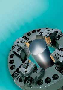
242 240
243 Drehschälen Bar peeling Unser komplettes Werkzeugprogramm für alle Typen von Drehschälmaschinen bestehend aus Wendeschneidplatten Kassetten Kassettenschlitten Wendeplatten-Schlitten Schälköpfen sowie unser Angebot an Ersatz- und Verschleißteilen für die Drehmaschine selbst, finden Sie in einem speziellen Katalog. Our complete tool program for all types of bar peeling machines consisting of carbide indexable inserts cartridges cartridge slides indexable insert slides bar peeling heads as well as spare parts and wear parts for the bar peeling machine itself is shown in a special catalogue. 241

244 242
The History Unternehmensgeschichte
 The History Unternehmensgeschichte Zhuzhou Cemented Carbide Cutting Tools Co. Ltd. (ZCC Cutting Tools), located at Zhuzhou, Hunan in P.R. China, is a subsidiary of ZCC Group which is a member of Minmetals
Drehwerkzeuge Turning Tools
 1 Gesamtkatalog General Catalogue 2009 1 2 VHM - Fräser 3 4 Cutting Tools 5 Cutting Tools 6 7 Short Hole Drills 8 VHM - Bohrer 9 Gesamtübersicht General View Tools Alphanumerischer Index / Alphanumeric
Das Werkzeugsystem im Überblick The Tool System Overview
 simturn E3 > Allgemeine Informationen // General Information E3 SIMTEK Turning Tools Type E3 Das Werkzeugsystem im Überblick The Tool System Overview 3 Schneiden... Präzision. Effizienz. Wirtschaftlichkeit.
FRÄSEN: WSP PCBN HAUPT-KATALOG 2.16 MILLING: INSERTS PCBN MAIN CATALOGUE 2.16
 FRÄSEN: WSP PCBN MILLING: INSERTS PCBN HAUPT-KATALOG 2.16 MAIN CATALOGUE 2.16 pcbn & PKD pcbn & PCD Negative Wendeschneidplatten negative inserts 49 M FRÄSEN MILLING WENDESCHNEIDPLATTEN INSERTS M.2.3 pcbn
Innovation in der Mikrobearbeitung
 Presseinformation August 2011 / 1. von 3 Seiten Werbung und PR Telefon (0 61 72) 1 06-461 Telefax (0 61 72) 1 06-213 E-Mail s.dillmann@wexo.com Innovation in der Mikrobearbeitung Neuer Mikrobohrer aus
premium carbide cutting tools Dümmel WERKZEUGFABRIK
 premium carbide cutting tools Dümmel WERKZEUGFABRIK Dümmel WERKZEUGFABRIK Inhalt Seite Zerspanungswerkzeuge vom Feinsten Contents premium carbide cutting tools page Bohrungsbearbeitung ab Ø mm grooving,
20% New ER chipbreaker, grade YBG205 Neu ER Spanbrecher, Sorte YBG205
 20% New ER chipbreaker, grade Neu ER Spanbrecher, Sorte ER Special chip breaker series for soft steel, stainless steel and heat resistant superalloy Spezielle Spanbrecherserie besonders für die Zerspanung
K210. Solid Carbide End Mills for Multi Purpose!! Vollhartmetallfräser für universellen Einsatz!!
 K2 Catalogue / 11 Solid Carbide End Mills for Multi Purpose!! Vollhartmetallfräser für universellen Einsatz!! Solid Carbide End Mills for Multi Purpose!! Vollhartmetallfräser für universellen Einsatz!!
Walter GPS Global Productivity System
 Walter GPS Global Productivity System DIE WERKZEUGAUSWAHL MIT dem ÜBERRASCHUNGS- EFFEKT. ÜBERRASCHEND EINFACH. THE TOOL SELECTION WITH THE ELEMENT OF SURPRISE. SURPRISINGLY EASY. Überraschend schnell:
SCHLITZFRÄSEN SLOT MILLING M101. ab Schneidkreis-Ø. from cutting edge Ø 80,0 mm width of groove 1,6-4,0 mm
 SHLITZFRÄSEN SLOT MILLING Schlitzfräser Slotting cutter ab Schneidkreis-Ø Nutbreite 80,0 mm 1,6-4,0 mm from cutting edge Ø 80,0 mm width of groove 1,6-4,0 mm 1 SHLITZFRÄSEN SLOT MILLING SHEIBENFRÄSER DIS
VOLLHARTMETALL-DIAMANT-REIBAHLENPROGRAMM
 VOLLHARTMETALL-DIAMANT-REIBAHLENPROGRAMM Reamer Description DIN Reamer Length Part Number Page Number Reamer Type Material Flutes Coating Ø in mm Coating Point Angle Direction of Cut Flute Style Techn.
PVD YB9320 NEW NEW. PVD Coated Cemented Carbide. PVD beschichtetes Hartmetall YBG205 YB9320
 NEW PVD NEW New coating technology with increased adhesion between coating and substrate and an excellent combination of toughness and hardness. The new grade also has a high temperature resistance. Suitable
Zahnstangen geschliffen, gerade & schräg Racks Ground, Straight & Helical Seiten pages B 3 - B 6
 Zahnstangen Racks Lagerprogramm Stock Programme Inhalt Content Zahnstangen geschliffen, gerade & schräg, Verzahnungsqualität 5 - NEU Racks Ground, Straight & Helical, Toothing Quality 5 - NEW Seiten pages
Messer und Lochscheiben Knives and Plates
 Messer und Lochscheiben Knives and Plates Quality is the difference Seit 1920 Since 1920 Quality is the difference Lumbeck & Wolter Qualität, kontinuierlicher Service und stetige Weiterentwicklung zeichnen
K-2 is micro grain size carbide end mills for general purpose such as slotting, side cutting and profiling. K-2 ist ein Feinstkorn
 K-2 is micro grain size carbide end mills for general purpose such as slotting, side cutting and profiling. K-2 ist ein Feinstkorn Vollhartmetallfräser für universellen Einsatz, wie Nutenfräsen, Seitenfräsen
Powerful + Energy Saving Leistungsstark + Energiesparend
 Cogeneration Plants Worldwide Powerful + Energy Saving Leistungsstark + Energiesparend Gas- and Diesel-CHP Gas- und Diesel-BHKW Powerful - Lindenberg-Anlagen GmbH The reputation of the company with its
Flexibel, schnell und preiswert durch eigene Konstruktion, Modellbau und Gießerei
 Armaturen für Industrie und Schiffbau Valves and fittings for industry and shipbuilding Stand 09/2007 Flexibel, schnell und preiswert durch eigene Konstruktion, Modellbau und Gießerei Flexible, fast and
NUTSTOßWERKZEUGE SLOTTING TOOLS
 NUTSTOßWERKZEUGE SLOTTING TOOLS 2016 TECHNOLOGY IN MOTION Nutstoßwerkzeuge Slotting Tools Nutstoßwerkzeuge Ideale Lösung für Nutstoßen auf Bearbeitungszentren und Drehmaschinen Werkzeuge gefertigt aus
Präzisionswerkzeuge MAIER. D max. GmbH
 Präzisionswerkzeuge MAIER D max GmbH THE Tools / Planfräser 45 Face milling cutter 45 Ausführung: leichtschneidender Schruppplanfräser mit vibrationsarmen Lauf, durch stark negativ - positive Schneidengeometrie,
SAAR-HARTMETALL UND WERKZEUGE
 Zerspanungswerkzeuge Hartmetall-Schneidwerkzeuge für die Bearbeitung von Stahl und Nichteisen-Werkstoffen, Gestein, Kunststoffen bis hin zu Lebensmitteln. utting tools utting inserts made of tungsten carbide
Fräs-System DA - für CNC-Drehmaschinen -
 TECHNOLOGIEVORSPRUNG IST HORN HORN - LEADERS IN GROOVING TECHNOLOGY NEU NEW Fräs-System DA - für CNC-Drehmaschinen - EINSTECHEN GROOVING ABSTECHEN PARTING OFF NUTFRÄSEN GROOVE MILLING NUTSTOSSEN BROACHING
Great assortment and development for professional wood working
 BEST OF TOOLS Sortimentsvielfalt und Top-Entwicklung für die professionelle Holz- und Kunststoffbearbeitung Great assortment and development for professional wood working WE DO IT. Unsere Werkzeuge werden
Reibahlen - Aufbohrer Reamers - Core drills
 Reibahlen - Aufbohrer Reamers - Core drills Inhaltsverzeichnis Index Werkzeug Gruppe 4: Reibahlen - Aufbohrer Tools Group 4: Reamers - Core drills Id. Nr. Code Seite Page Einführung Introduction 269 275
SYSTEM DAH SYSTEM DAH
 SYSTEM DAH SYSTEM DAH 18 Hochvorschubfräsen System DAH High feed milling System DAH Die neue Fräsgeneration The Generation of Milling Tools HCHVRSCHUBFRÄSEN HIGH FEED MILLING FRÄSERSCHAFT MILLING SHANK
Ultramini. Dümmel WERKZEUGFABRIK. Bohrungsbearbeitung ab ø 0.2 mm. grooving, boring and profiling starting at ø 0.2 mm
 Ultramini Dümmel WERKZEUGFABRIK Bohrungsbearbeitung ab ø 0.2 mm grooving, boring and profiling starting at ø 0.2 mm ULTRAMINI ÜBERSICHT Bohrungsbearbeitung ab ø 0.2 mm grooving, boring and profiling starting
General Turning /Allgemeine Drehbearbeitung, ISO Kennzeichnung. The new graphite cutters for the machining of graphite electrodes
 General Turning /Allgemeine Drehbearbeitung, ISO Kennzeichnung GP Series GP Serie Our program Unser Programm Our program Unser Programm The new graphite cutters for the machining of graphite electrodes
System DS zum Hartfräsen. System DS for hard milling. Solid carbide endmills for machining hardened steels from 50-70 HRC
 EINSTECHEN ABSTECHEN NUTFRÄSEN NUTSTOSSEN KOPIERFRÄSEN BOHREN REIBEN NEU System DS zum Hartfräsen VHM-Fräserreihe zur Bearbeitung gehärteter Stähle von 50-70 HRC NEW System DS for hard milling Solid carbide
382/383 HOCHLEISTUNGS-SCHEIBENFRÄSER HIGH PERFORMANCE DISC MILLING CUTTER
 HOCHLEISTUNGS-SCHEIBENRÄSER HIGH PERORMANCE DISC MILLING CUTTER 382/383 Universelle Schneidengeometrie für Stahl und Leichtmetall 10 positiver Spanwinkel Gute Spanausbringung Hervorragende Schnittleistung
Standard-Kettenräder für Rollenketten nach DIN und ASA Standard-Sprockets for Roller Chains to DIN and ASA
 Standard-Kettenräder für Rollenketten nach DIN und ASA Standard-Sprockets for Roller Chains to DIN and ASA Lagerprogramm Stock Programme Inhalt Kettenradscheiben und Kettenräder - en von 6 mm bis 50,8
Supplier Questionnaire
 Supplier Questionnaire Dear madam, dear sir, We would like to add your company to our list of suppliers. Our company serves the defence industry and fills orders for replacement parts, including orders
VGM. VGM information. HAMBURG SÜD VGM WEB PORTAL USER GUIDE June 2016
 Overview The Hamburg Süd VGM Web portal is an application that enables you to submit VGM information directly to Hamburg Süd via our e-portal Web page. You can choose to enter VGM information directly,
Deceleration Technology. Rotary Dampers with high-torque range WRD-H 0607 WRD-H 0805 WRD-H 1208 WRD-H 1610 WRD-H
 Rotary Dampers with high-torque range WRD-H 67 WRD-H 85 WRD-H 128 WRD-H 161 WRD-H 21 Deceleration Technology ONLINE CALCULATION AND 2D / 3D CAD DOWNLOAD M m L F Benefits Applications: - Mechanical and
a new line of steam sterilizers
 a new line of steam sterilizers ticheeasy to use and high consumption savings multifunction display controlled by micro-processor double and patented motor-operated closure stainless steel chamber without
SYSTEM DA SYSTEM DA. System DA. System DA. Die neue Fräsgeneration. The Generation of Milling Tools
 SYSTEM DA SYSTEM DA System DA System DA Die neue Fräsgeneration The Generation of Milling Tools 1 FRÄSEN MESSERKPF CUTTER DAM Schneidkreis-Ø Cutting edge Ø 40/50/63 mm Aufsteckfräser nach DIN 8030-A Arbor
Customer-specific software for autonomous driving and driver assistance (ADAS)
") This press release is approved for publication. Press Release Chemnitz, February 6 th, 2014 Customer-specific software for autonomous driving and driver assistance (ADAS) With the new product line Baselabs
This press release is approved for publication. Press Release Chemnitz, February 6 th, 2014 Customer-specific software for autonomous driving and driver assistance (ADAS) With the new product line Baselabs
DIE NEUORGANISATION IM BEREICH DES SGB II AUSWIRKUNGEN AUF DIE ZUSAMMENARBEIT VON BUND LNDERN UND KOMMUNEN
 DIE NEUORGANISATION IM BEREICH DES SGB II AUSWIRKUNGEN AUF DIE ZUSAMMENARBEIT VON BUND LNDERN UND KOMMUNEN WWOM537-PDFDNIBDSIAADZVBLUK 106 Page File Size 4,077 KB 16 Feb, 2002 COPYRIGHT 2002, ALL RIGHT
VGM. VGM information. HAMBURG SÜD VGM WEB PORTAL - USER GUIDE June 2016
 Overview The Hamburg Süd VGM-Portal is an application which enables to submit VGM information directly to Hamburg Süd via our e-portal web page. You can choose to insert VGM information directly, or download
Wendeplatten-programm zur Stahlbearbeitung
 DURATOMIC Wendeplatten-programm zur Stahlbearbeitung höchste standzeiten beim drehen NEU! NEU! - Für maximale Produktivität Die Anforderungen Ihrer Kunden steigen und der Wettbewerb im Markt nimmt drastisch
Exercise (Part XI) Anastasia Mochalova, Lehrstuhl für ABWL und Wirtschaftsinformatik, Kath. Universität Eichstätt-Ingolstadt 1
 Anastasia Mochalova, Lehrstuhl für ABWL und Wirtschaftsinformatik, Kath. Universität Eichstätt-Ingolstadt 1") Exercise (Part XI) Notes: The exercise is based on Microsoft Dynamics CRM Online. For all screenshots: Copyright Microsoft Corporation. The sign ## is you personal number to be used in all exercises. All
Exercise (Part XI) Notes: The exercise is based on Microsoft Dynamics CRM Online. For all screenshots: Copyright Microsoft Corporation. The sign ## is you personal number to be used in all exercises. All
series end mills for machining aluminum Serie VHM-Schaftfräser für die Bearbeitung von Aluminium
 series end mills for machining aluminum Serie VHMSchaftfräser für die earbeitung von Aluminium 356 Complete product category for machining Al from general to ultra high speed. Tool type / Werkzeug: AL3ED6.0
Threading Terminology. Unterlegplatte. Für weitere Informationen über Vardex Gewindedrehen Lösungen: www.vargus.com
 Threading Terminology English Adapter Adjusted Major Diameter Anvil Axial Divide Boring Insert Carbide cutting tool Carbide grade Carbide indexable insert Carbide insert Chamfer Chipflow Clamping System
eurex rundschreiben 094/10
 eurex rundschreiben 094/10 Datum: Frankfurt, 21. Mai 2010 Empfänger: Alle Handelsteilnehmer der Eurex Deutschland und Eurex Zürich sowie Vendoren Autorisiert von: Jürg Spillmann Weitere Informationen zur
PRÄZISION. Katalog Catalogue
 PRÄZISION Katalog Catalogue Präzisionswerkzeuge in Vollhartmetall, Diamant und Cermets zum Bohren Senken Reiben Precision tools in solid carbide, diamond and cermets for drilling countersinking reaming
B 1 - B 4 B 5 - B 6 B 7 - B 9 B 10 B 11 - B 13 B 14 B 15 & B 17 - B 18 B 16 B 19 B 20 - B 24 B 25 B 26 - B 27 B 28 - B 29 B 29
 Zahnstangen Racks Lagerprogramm stock programme Zahnstangen geschliffen, gerade & schräg Zahnstangen vergütet, gerade & schräg Zahnstangen induktiv gehärtet, gerade & schräg Zahnstangen rostfrei Zahnstangen
PRÄZISION. Katalog Catalogue. Präzisionswerkzeuge in Vollhartmetall und Diamant zum Fräsen Precision milling tools in solid carbide and diamond
 PRÄZISION Katalog Catalogue Präzisionswerkzeuge in Vollhartmetall und Diamant zum Fräsen Precision milling tools in solid carbide and diamond 2010/11 M Schaftfräser Vollhartmetall-Hochleistungsfräser für
Hartmetall - Kegelsenker Carbide countersinks
 Hartmetall - Kegelsenker Carbide countersinks Inhaltsverzeichnis Index Werkzeug Gruppe 5: Hartmetall - Kegelsenker Tools Group 5: Carbide countersinks Id. Nr. Code Seite Page Einführung Introduction 282
IN-Line NEW. Applitec Moutier S.A. Ch. Nicolas-Junker 2 CH-2740 Moutier. Tél. +41 32 494 60 20 Fax +41 32 493 42 60 www.applitec-tools.
 IN-Line NEW Applitec Moutier S.A. Ch. Nicolas-Junker 2 CH-2740 Moutier Tél. +41 32 494 60 20 Fax +41 32 493 42 60 www.applitec-tools.com IN-Line With trough tool coolant PATENT PENDING PRECISION RIGIDITY
Network premium POP UP Display
 Premium Pop Up System seamless graphic precision very compact and versatile pop-up system quick to set up at any location comes in a number of different shapes; straight, curved, wave-shaped, stair formations,
ERHARD is a company of. Datasheet ERHARD ECR check valve
 ERHARD is a company of Datasheet The compact check valve for clamping The is clamped between two flanges as a reflux preventer. It has two vanes which, for example, open on starting a pump and will iediately
Aluminiumbearbeitung. Drehen, Fräsen, Pentatec, Stechdrehen, Ein- und Abstechen Aluminium machining
 Aluminiumbearbeitung Drehen, Fräsen, Pentatec, Stechdrehen, Ein- und Abstechen Aluminium machining Turning, Milling, Pentatec, Groove-turning, Parting and Grooving Alutec: Das Alutecprogramm zeichnet sich
Plattenkollektion Panel Collection
 Plattenkollektion Panel Collection Acrylux Wir liefern 20 aktuelle Acrylux-Oberflächen auf unterschiedlichen Trägermaterialien und diversen Plattenstärken, einseitig oder beidseitig beschichtet. Die Flächen
VARDEX Threading Around The World. Unterlegplatte
 VARDEX Threading Around The World English German Adapter Adjusted Major Diameter Anvil Axial Divide Boring Insert Carbide cutting tool Carbide grade Carbide indexable insert Carbide insert Chamfer Chipflow
Level 2 German, 2013
 91126 911260 2SUPERVISOR S Level 2 German, 2013 91126 Demonstrate understanding of a variety of written and / or visual German text(s) on familiar matters 9.30 am Monday 11 November 2013 Credits: Five
Titanium The heaviest light metal
 Titanium The heaviest light metal Dan Snitkovsky Uniweld Israel FRONIUS International GmbH Buxbaumstr. 2 4600 Wels Titanium The heaviest light metal 0,5g/cm³ 4,5g/cm³ Heavy metal Lithium - light metal
PROFICOIL. Professional Thread Repairing System
 PROFICOIL Professional Thread Repairing System GEWINDEREPARATUR THREAD REPAIRING PROFICOIL Gewindereparatur-Sortimente Thread Repairing Assortments metrisch / metrisch fein 3 Gewindereparatur-Sets Thread
Die MK-Tools-Service GmbH wurde 2001 von Helmut Miller und
 2013/2014 Die MK-Tools-Service GmbH wurde 2001 von Helmut Miller und Stephan Kinateder als Nachschärfbetrieb für Vollhartmetall- Werkzeuge gegründet. Durch konsequenten Einsatz neuster Technologie konnten
Lehrstuhl für Allgemeine BWL Strategisches und Internationales Management Prof. Dr. Mike Geppert Carl-Zeiß-Str. 3 07743 Jena
 Lehrstuhl für Allgemeine BWL Strategisches und Internationales Management Prof. Dr. Mike Geppert Carl-Zeiß-Str. 3 07743 Jena http://www.im.uni-jena.de Contents I. Learning Objectives II. III. IV. Recap
Deceleration Technology. Rotary Dampers with high-torque range WRD-H 7550 WRD-H 9565 WRD-H
 Rotary Dampers with high-torque range WRD-H 7550 WRD-H 9565 WRD-H 12070 Deceleration Technology ONLINE CALCULATION AND 2D / 3D CAD DOWNLOAD M m L F Benefits Material: - Aluminium and steel Applications:
GAUSS towards a common certification process for GNSS applications using the European Satellite System Galileo
 GAUSS towards a common certification process for GNSS applications using the European Satellite System Galileo Matthias Grimm, Dr. Michael Meyer zu Hörste Vortragstitel > 11. Juni 2010 > Folie 1 Agenda
Aluminiumbearbeitung. Drehen, Fräsen, Pentatec, Stechdrehen, Ein- und Abstechen Aluminium machining
 Aluminiumbearbeitung Drehen, Fräsen, Pentatec, Stechdrehen, Ein- und Abstechen Aluminium machining Turning, Milling, Pentatec, Groove-turning, Parting and Grooving www.boehlerit.com Alutec: Das Alutecprogramm
Notice: All mentioned inventors have to sign the Report of Invention (see page 3)!!!
!!!") REPORT OF INVENTION Please send a copy to An die Abteilung Technologietransfer der Universität/Hochschule An die Technologie-Lizenz-Büro (TLB) der Baden-Württembergischen Hochschulen GmbH Ettlinger Straße
REPORT OF INVENTION Please send a copy to An die Abteilung Technologietransfer der Universität/Hochschule An die Technologie-Lizenz-Büro (TLB) der Baden-Württembergischen Hochschulen GmbH Ettlinger Straße
EXZELLENT II BESTECKEINSÄTZE CUTLERY INSERTS. spacious customized stability easy to adapt reliable
 BESTECKEINSÄTZE CUTLERY INSERTS August Ottensmeyer EXZELLENT II geräumig maßgeschneiderte Stabilität simpel adaptierbar zuverlässig spacious customized stability easy to adapt reliable EXZELLENT II Besteckeinsätze
Neue Fräsgeneration System DA
 Neue Fräsgeneration System DA New generation of Milling Tools System DA 1 TAUCHFRÄSEN PUNGE MIING FRÄSERSCHAFT Typ MIING SHANK Type DAM31/DAM32 Schneidkreis-Ø Cutting edge Ø 32/25/20/16 mm Schaftmaterial:
TERA-Drill. Standard Range. Standardprogramm
 TERA-Drill Standardprogramm Standard Range Zerspanungswerkzeuge Sondermaschinen Messtechnik Cutting Tools Special Mechanical Engineering Measurement Equipment BLICKLE Werkzeuge GmbH & Co. KG Ölbergstr.
NEWSLETTER. FileDirector Version 2.5 Novelties. Filing system designer. Filing system in WinClient
 Filing system designer FileDirector Version 2.5 Novelties FileDirector offers an easy way to design the filing system in WinClient. The filing system provides an Explorer-like structure in WinClient. The
neu! Hohe Prozeßsicherheit beim Stechdrehen G.T.S. - Systemvorteile www.jd-tools.de Nr. 300/2012-DE GP 2120 GM 5130
 Nr. 300/2012-DE G.T.S.-Stechdrehsystem Hohe Prozeßsicherheit beim Stechdrehen GP 2120 GM 5130 neu! G.T.S. - Systemvorteile Einzigartiges W-Klemmsystem sorgt für stabile Stechoperation, vor allem beim Stechdrehen
Flexibel, schnell und preiswert durch eigene Konstruktion, Modellbau und Gießerei
 Armaturen für Industrie und Schiffbau Valves and fittings for industry and shipbuilding Flexibel, schnell und preiswert durch eigene Konstruktion, Modellbau und Gießerei Flexible, fast and low prices because
Speetronics Technologies
 Speetronics Technologies spee tronics T E C H N O L O G I E S Design / Engineering Manufacturing / Assembly Quality Management / Logistics Know-How Durch das fundierte Know How ist Speetronics GmbH ein
Axialeinstechen mit URMA-IntraMax und Ausspindeln mit URMA-Feinbohrkopf
 Axialeinstechen mit URMA-IntraMax und Ausspindeln mit URMA-Feinbohrkopf Face grooving with URMA IntraMax and boring with URMA fine boring head Synergieeffekte nutzen Benefits of Synergy 1 Ausspindeln mit
General Turning /Allgemeine Drehbearbeitung, ISO Kennzeichnung
 QCH - APKT ap Dimensions (mm) e Stock Abmessungen Lager ØD ØD1 L ap MD QCH -16-APKT11-M8-02 16 12.5 25 10.5 8 Insert WSP No. of Weight teeth Gewicht Zähne (kg) (Z) 2 0.028-20-APKT11-M10-03 20 18 30 10.5
Patentrelevante Aspekte der GPLv2/LGPLv2
 Patentrelevante Aspekte der GPLv2/LGPLv2 von RA Dr. Till Jaeger OSADL Seminar on Software Patents and Open Source Licensing, Berlin, 6./7. November 2008 Agenda 1. Regelungen der GPLv2 zu Patenten 2. Implizite
Produktkatalog CBN-Wendeschneidplatten
 Produktkatalog CBN-Wendeschneidplatten Mai 2015 Dia Cutting Tools Die Firma Dia Cutting Tools mit Hauptsitz in Thüringen/Tiefenort hat sich auf die Herstellung, die Entwicklung und den Vertrieb von Präzisionswerkzeugen
Bohren von Composite/Metall Hybrid Material in der Flugzeugmontage
 Bohren von Composite/Metall Hybrid Material in der Flugzeugmontage Eine Prozessanalyse Bohren von Composite/Metall Hybrid Material in der Flugzeugmontage / MAPAL / Dr. Müller-Hummel 1. Dezember 2014 1
Präzisionsführungswellen Precision Guide shafts
 75 Katalog 04 Linearlager und lineareinheiten Catalog 04 linear ball bushings and linear bearing housings 05 Präzisionsführungswellen Precision Guide shafts 75 Präsizionsführungswellen 05 Precision guide
BESTECKEINSÄTZE CUTLERY INSERTS. August Ottensmeyer FORNO. functional straight-lined modern longlasting. funktionell gradlinig modern langlebig
 BESTECKEINSÄTZE CUTLERY INSERTS August Ottensmeyer FORNO funktionell gradlinig modern langlebig functional straight-lined modern longlasting FORNO Besteckeinsätze In manchen Einbauküchen ist Platz Mangelware
p^db=`oj===pìééçêíáåñçêã~íáçå=
 p^db=`oj===pìééçêíáåñçêã~íáçå= How to Disable User Account Control (UAC) in Windows Vista You are attempting to install or uninstall ACT! when Windows does not allow you access to needed files or folders.
Schilder. Willkommen in der. fabrik...
 Schilder Willkommen in der fabrik... Unsere Tradition hat uns geprägt... Schilder Schilder stellen in unserem Alltag eine wichtige Informationsquelle und Orientierungshilfe dar. Vor allem in Form von Kfz-Kennzeichen
PRÄZISION. HAM Superdrill Drills for Highest Demands Vollhartmetall-Hochleistungsbohrer für höchste Ansprüche
 PRÄZISION Precision Tools in Solid Carbide High Performance Drills - Program Choices for your Production Präzisionswerkzeuge in Vollhartmetall - Hochleistungsbohrer Auswahlprogra für Ihre Fertigung HAM
INTERREG IIIa Project R&D - Ready for Research and Development Project results and ongoing activities
 INTERREG IIIa Project R&D - Ready for Research and Development Project results and ongoing activities Györ, 5th December 2007 Key regions + perifary for surveys Background objectives CENTROPE needs a strategy
Exercise (Part II) Anastasia Mochalova, Lehrstuhl für ABWL und Wirtschaftsinformatik, Kath. Universität Eichstätt-Ingolstadt 1
 Anastasia Mochalova, Lehrstuhl für ABWL und Wirtschaftsinformatik, Kath. Universität Eichstätt-Ingolstadt 1") Exercise (Part II) Notes: The exercise is based on Microsoft Dynamics CRM Online. For all screenshots: Copyright Microsoft Corporation. The sign ## is you personal number to be used in all exercises. All
Exercise (Part II) Notes: The exercise is based on Microsoft Dynamics CRM Online. For all screenshots: Copyright Microsoft Corporation. The sign ## is you personal number to be used in all exercises. All
Best of Gewindebohrer. Mini-Stechen. AL-Wendeplatten neu! Drehwendeschneidplatten. Microcut-Fräser. neu! 69/2008-D-HTT
 Gültig vom 01.09. - 30.11.2008 Best of 2008 Produkte und Angebote rund um die Zerspanung 69/2008-D-HTT Gewindebohrer Mini-Stechen AL-Wendeplatten VCGT 13 03 02 AL H10F VCGT 13 03 04 AL H10F Drehwendeschneidplatten
OP-SUCTION SETS / HANDPIECES. Innovative plastic products and systems for medicine and technology. Fon: +49 (0)
") Systems for your life... OP-SUCTION SETS / HANDPIECES Innovative plastic products and systems for medicine and technology 1 Product Description As one of Europe s leading suppliers, we produce an extensive
Systems for your life... OP-SUCTION SETS / HANDPIECES Innovative plastic products and systems for medicine and technology 1 Product Description As one of Europe s leading suppliers, we produce an extensive
C-TEC Systemtechnik und Serviceleistung für die Werkstoffprüfung GmbH
 C-TEC Systemtechnik und Serviceleistung C-TEC Systemtechnik und Serviceleistung The Origin of the company C-TEC: Foundation in 1994 Commercial basis: development of Pipeline Crawlers In 1995 the first
Prediction Market, 28th July 2012 Information and Instructions. Prognosemärkte Lehrstuhl für Betriebswirtschaftslehre insbes.
 Prediction Market, 28th July 2012 Information and Instructions S. 1 Welcome, and thanks for your participation Sensational prices are waiting for you 1000 Euro in amazon vouchers: The winner has the chance
Level 2 German, 2015
 91126 911260 2SUPERVISOR S Level 2 German, 2015 91126 Demonstrate understanding of a variety of written and / or visual German text(s) on familiar matters 2.00 p.m. Friday 4 December 2015 Credits: Five
STALE. Werkzeugmaschinen. GmbH. Werkzeughalter & Spannzangen Toolholders & Collets. made in europe. www.stalex.de
 STALE Werkzeugmaschinen GmbH Werkzeughalter & Spannzangen Toolholders & Collets made in europe www.stalex.de Inhalt Content Werkzeughalter Toolholders Seiten Pages ER Zangen Aufnahmen 5-7 ER Collet Chucks
Gern beraten wir auch Sie. Sprechen Sie uns an!
 de en Unter dem Motto wire Solutions bietet die KIESELSTEIN International GmbH verschiedenste Produkte, Dienstleistungen und After Sales Service rund um den Draht an. Die Verbindung von Tradition und Innovation
Kuhnke Technical Data. Contact Details
 Kuhnke Technical Data The following page(s) are extracted from multi-page Kuhnke product catalogues or CDROMs and any page number shown is relevant to the original document. The PDF sheets here may have
NETWORK PREMIUM POP UP DISPLAY
 Premium Pop Up System seamless graphic precision very compact and versatile pop-up system quick to set up at any location comes in a number of different shapes; straight, curved, wave-shaped, stair formations,
Hufschmied Fräser zur Tiefziehteile-Bearbeitung Hufschmied mills for deepdrawing-moulders
 Hufschmied Fräser zur Tiefziehteile-Bearbeitung Hufschmied mills for deepdrawing-moulders Hufschmied Zerspanungssysteme GmbH Edisonstraße 11d D-86399 Bobingen Telefon: 0 82 34-96 64 0 Telefax: 0 82 34-96
HDS -Fräser. -Special. -Endmills. Increase in productivity at low tool cost thanks to newly developed tool material HARDAL SUPRA
 -Special SP102/2015-DE/GB/WV HDS -Fräser -Endmills Die leistungsstarke Alternative zu konventionellen HSS- und VHM-Fräsern. The powerful alternative compared with conventional H.S.S.-and carbide endmills.
4G Mill. 4G Mill FRÄSER. CARBIDE Being the best through innovation. - High Speed Cutting for Pre-Hardened Steels up to HRc55
 CABIDE Being the best through innovation G G FÄSE High Speed Cutting for PreHardened up to Hc HighSpeedBearbeitung (HSC) von vorvergüteten Stählen bis Hc SELECTION GUIDE SIZE ITEM MODEL DESCIPTION PAGE
Titelbild1 ANSYS. Customer Portal LogIn
 Titelbild1 ANSYS Customer Portal LogIn 1 Neuanmeldung Neuanmeldung: Bitte Not yet a member anklicken Adressen-Check Adressdaten eintragen Customer No. ist hier bereits erforderlich HERE - Button Hier nochmal
Corporate Digital Learning, How to Get It Right. Learning Café
 0 Corporate Digital Learning, How to Get It Right Learning Café Online Educa Berlin, 3 December 2015 Key Questions 1 1. 1. What is the unique proposition of digital learning? 2. 2. What is the right digital
Leading the innovation in the traditional field of Constructions. C. Chiti, Technical Director Knauf Italy
 Leading the innovation in the traditional field of Constructions C. Chiti, Technical Director Knauf Italy 1 The Knauf Group The Knauf Group today is one of the leading companies in the building materials
Symbio system requirements. Version 5.1
 Symbio system requirements Version 5.1 From: January 2016 2016 Ploetz + Zeller GmbH Symbio system requirements 2 Content 1 Symbio Web... 3 1.1 Overview... 3 1.1.1 Single server installation... 3 1.1.2
p^db=`oj===pìééçêíáåñçêã~íáçå=
 p^db=`oj===pìééçêíáåñçêã~íáçå= Error: "Could not connect to the SQL Server Instance" or "Failed to open a connection to the database." When you attempt to launch ACT! by Sage or ACT by Sage Premium for
Technologien & Märkte Technologies & Markets
 Metal concepts Metallkonzepte 02 Technologien & Märkte Technologies & Markets... Wir entwickeln und fertigen unsere Produkte komplett im eigenen Haus. Engagierte und kompetente Mitarbeiter bedienen CNC-gesteuerte
T-NUTEN-FRÄSEN MILLING OF T-SLOTS. Hervorragende Spanausbringung durch späneausflutende, zentrale Kühlmittelzufuhr.
 T-NUTEN-RÄSEN MILLING O T-SLOTS Hervorragende Spanausbringung durch späneausflutende, zentrale Kühlmittelzufuhr. Excellent removal of chips, flushed by through coolant supply. 1 T-NUTEN-RÄSEN MILLING O
Level 1 German, 2014
 90886 908860 1SUPERVISOR S Level 1 German, 2014 90886 Demonstrate understanding of a variety of German texts on areas of most immediate relevance 9.30 am Wednesday 26 November 2014 Credits: Five Achievement