(51) Int Cl.: G01R 31/08 ( )
|
|
|
- Kora Müller
- vor 8 Jahren
- Abrufe
Transkript
1 (19) (12) EUROPEAN PATENT SPECIFICATION (11) EP B1 (4) Date of publication and mention of the grant of the patent: Bulletin 12/0 (21) Application number: (22) Date of filing: (1) Int Cl.: G01R 31/08 (06.01) (86) International application number: PCT/US08/ (87) International publication number: WO 09/0819 ( Gazette 09/19) (4) SCALABLE CONNECTIVITY FAULT MANAGEMENT IN A BRIDGED/VIRTUAL PRIVATE LAN SERVICE ENVIRONMENT FEHLERVERWALTUNG SKALIERBARER KONNEKTIVITÄT IN EINER BRÜCKEN- BZW. VIRTUELLEN PRIVATEN LAN-DIENSTUMGEBUNG GESTION D ERREURS DE CONNECTIVITÉ POUVANT ÊTRE MISE À L ÉCHELLE DANS UN ENVIRONNEMENT DE SERVICE DE RÉSEAU LOCAL (LAN) PRIVÉ PONTÉ/VIRTUEL (84) Designated Contracting States: AT BE BG CH CY CZ DE DK EE ES FI FR GB GR HR HU IE IS IT LI LT LU LV MC MT NL NO PL PT RO SE SI SK TR () Priority:..07 US US US 0121 (43) Date of publication of application: Bulletin /32 (73) Proprietor: Ericsson AB Stockholm (SE) KINI, Sriganesh San Jose CA 9134 (US) (74) Representative: HOFFMANN EITLE Patent- und Rechtsanwälte Arabellastraße München (DE) (6) References cited: WO-A1-07/02 WO-A2-07/11 US-A US-A US-A US-A US-B (72) Inventors: MEHTA, Rishi San Jose CA 9136 (US) EP B1 Note: Within nine months of the publication of the mention of the grant of the European patent in the European Patent Bulletin, any person may give notice to the European Patent Office of opposition to that patent, in accordance with the Implementing Regulations. Notice of opposition shall not be deemed to have been filed until the opposition fee has been paid. (Art. 99(1) European Patent Convention). Printed by Jouve, 7001 PARIS (FR)
 Priority:..07 US 110 17.03.")
2 1 EP B1 2 Description BACKGROUND Field [0001] Embodiments of the invention relate to the field of computer networking; and more specifically, supporting scalable connection fault management (CFM) in a bridged or virtual private local area network (LAN) service environment. Background [0002] Operation, Administration, and Maintenance (OAM) describes processes, activities, tools, standards, etc., involved with operating, administering, and maintaining computer networks. OAM is implemented for many different types of computer networks, such Ethernet, Internet Protocol (IP), multi-protocol label switching (MPLS), asynchronous transfer mode (ATM), virtual private LAN service (VPLS), etc. Each type of network will have a different type of OAM. For example, in an Ethernet network, 802.1ag Connectivity Fault Management (CFM) is used as an OAM management tool, and in a MPLS/ VPLS network Virtual Circuit Connectivity Verification (VCCV) is used as an OAM tool. OAM tools are used, in part, to detect network connectivity faults, herein referred to as faults. A fault can be when a network device loses connectivity to the network. OAM tools detect a fault state change, such when a device becomes active on the network, by connecting to the network or becoming active on the network. Furthermore, a fault state change can be when a network loses connectivity to the network. [0003] Figure 1 illustrates one embodiment of network 0 CFM across a switched Ethernet and VPLS/MPLS environment. Network 0 is a heterogeneous network comprising two switched Ethernet networks 116A-B interconnected by a VPLS service provider network 6. In Figure 1, Ethernet networks 116A-B are geographically dispersed. VPLS is a way to provide Ethernet based multipoint-to-multipoint communication over IP/MPLS networks. It allows geographically dispersed sites, such as Ethernet networks 116A-B to share an Ethernet broadcast domain by connecting sites through psuedowires. In VPLS, the LAN of each Ethernet network 116A-B is extended to edge of service provider network 6 and service provider network 6 emulates a switch or bridge to connect the customer LANs of Ethernet networks 116A-B to create a single bridged LAN. Coupling switched Ethernet networks 116A-B and VPLS network 6 at the edge of each network are network elements 4A-B. While in one embodiment, network elements 4A-B are edge routers, in alternative embodiments, network elements 4A-B are the same and/or different type of network element (switch, router, core router, etc.) For example, network element 4A couples switched Ethernet network 116A and VPLS network 6, while network element 4B couples switched Ethernet network 116B and VPLS network 6. [0004] Each of switched Ethernet networks comprises maintenance endpoints (MEPs) coupled to the edge network elements. An MEPs is an actively managed CFM entity which can generate & receive CFM messages and track any responses such as personal computers, servers, bridges, switches, and other possible devices participating in Ethernet network. As illustrated in Figure 1, Ethernet network 116A comprises maintenance endpoints 2A-C coupled to network element 4A and Ethernet network 116B comprises maintenance endpoints 2D-F coupled to network element 4B. [000] VPLS network 6 comprises network elements 8A-D, where network elements 8A and C couple to network element 4A and network elements 8B and D couple to network element 4B. Network elements 8A-B forward traffic between network elements 4A-B with pseudowire 1A. Network elements 8C-D forward traffic between network elements 4A- B with pseudowire 1B. [0006] CFM is a standard that specifies protocols and protocol entities within virtual LAN (VLAN) aware bridges (such as network elements 4A-B) that provides capabilities for detecting, verifying, and isolating faults in VLANs. These capabilities can be used in networks operated by multiple independent organizations, each with restricted management access to each other s equipment. CFM defines a maintenance domain that as a network or part of the network for which faults in connectivity can be managed. Within each maintenance domain, there are several MEPs. An MEP is an actively managed CFM entity, which initiates, terminates, and reacts to CFM flows associated within a specific maintenance domain. Periodically, each MEP sends connectivity check messages to the other MEP in the maintenance domain. The connectivity check message is a multicast, unidirectional heartbeat that signals that the MEP sending the connectivity check message is up and coupled to the network. An MEP sending an initial connectivity check message signifies to other MEPs in the maintenance domain that the MEP has become active in this domain. Lack of connectivity check message from a particular MEP indicates to the other MEPs that the particular MEP is down or not participating in the domain. [0007] In Figure 1, MEPs 2A-C and D-F periodically send out connectivity check messages 112A-C and 114A-C, respectively. Each MEP can send out connectivity check messages every 3.3 milliseconds. These messages are multicast to all the other MEPs in the maintenance domain. Because the MEPs of the different Ethernet networks 116A-D belong to the same maintenance domain, the connectivity check messages are transmitted across VPLS network 6 via network elements 4AB to the MEPs in different Ethernet networks 116AB. In addition, because the connectivity check messages are multicast, network elements 4AB broadcast these messages to each of the pseudowires coupled to 2
![Background [0002] Operation, Administration, and Maintenance (OAM) describes processes, activities, tools, standards, etc., involved with operating, administering, and maintaining computer networks.](/docs-images/55/10055543/images/page_2.jpg "OAM is implemented for many different types of computer networks, such Ethernet, Internet Protocol (IP), multi-protocol label switching (MPLS), asynchronous transfer mode (ATM), virtual private LAN")
3 3 EP B1 4 the respective network element 4AB in VPLS network 6. US Patent Application Publication US 07/00226 A1 discloses connection verification by transmitting a loopback message by a MEP on a BRAS of an Ethernet access domain to determine whether a target MEP is reachable. A virtual MEP, running on a DSLAM, receives the loopback message, translates it into a link level OAM message, as e.g a connectivity check message, and sends it to a residential gateway to check the path between RCi and access node. [0008] Although CFM can provide an end-to-end fault management scheme for heterogeneous network 0, CFM is not scalable because of the flooding of the connectivity check (CC) messages by network elements 4A-B. As the number of MEPs in the maintenance domain increase, the amount of CC messages transmitted across VPLS network increases dramatically. BRIEF SUMMARY [0009] A method and apparatus that proxies connectivity check messages and sends fault state changes messages across an MPLSNPLS network is described. A network element proxies connectivity check messages for remote maintenance endpoints based on a local database. The network element updates the database based on received fault state change message that identify a fault state change of a remote maintenance endpoint. The network element detects fault state changes of local maintenance endpoints and sends a fault state change message to other network elements that proxy connectivity check messages for the local maintenance endpoints. BRIEF DESCRIPTION OF THE DRAWINGS [00] Embodiments of the invention may be best understood by referring to the following description and accompanying drawings which illustrate such embodiments. The numbering scheme for the Figures included herein is such that the leading number for a given element in a Figure is associated with the number of the Figure. However, element numbers are the same for those elements that are the same across different Figures. In the drawings: [0011] Figure 1 (Prior Art) illustrates one embodiment of network supporting CFM across a switched Ethernet and VPLS/MPLS environment. [0012] Figure 2 is a block diagram of a network element that supports proxying connectivity check messages for remote MEPs and sending VCCV messages to other network elements based on MEP fault state changes according to one embodiment of the invention. [0013] Figure 3 is illustrates one embodiment of a network supporting scalable CFM across a switched Ethernet and VPLS/MPLS environment according to one embodiment of the invention. [0014] Figure 4 is an exemplary flow diagram for proxying CC messages for remote MEPs according to one embodiment of the invention. [001] Figure is an exemplary flow diagram for sending VCCV messages to other network elements based on MEP fault state changes according to one embodiment of the invention. [0016] Figure 6 is a block diagram illustrating an exemplary network element that handles proxying CC messages and sending VCCV messages according to one embodiment of the system. DETAILED DESCRIPTION [0017] In the following description, numerous specific details such as network element, line card, fault, fault management, packet, maintenance endpoint, LAN, VPLS, MPLS and interrelationships of system components are set forth in order to provide a more thorough understanding of the invention. In other instances, control structures, gate level circuits and full software instruction sequences have not been shown in detail in order not to obscure the invention. Those of ordinary skill in the art, with the included descriptions, will be able to implement appropriate functionality without undue experimentation. [0018] References in the specification to "one embodiment", "an embodiment", "an example embodiment", etc., indicate that the embodiment described may include a particular feature, structure, or characteristic, but every embodiment may not necessarily include the particular feature, structure, or characteristic. Moreover, such phrases are not necessarily referring to the same embodiment. Further, when a particular feature, structure, or characteristic is described in connection with an embodiment, it is submitted that it is within the knowledge of one skilled in the art to affect such feature, structure, or characteristic in connection with other embodiments whether or not explicitly described. [0019] In the following description and claims, the term "coupled," along with its derivatives, is used. "Coupled" may mean that two or more elements are in direct physical or electrical contact. However, "coupled" may also mean that two or more elements are not in direct contact with each other, but yet still co-operate or interact with each other. Exemplary embodiments of the invention will now be described with reference to Figures 2-6. In particular, the operations of the flow diagrams in Figures 4 and will be described with reference to the exemplary embodiments of Figures 2, 3 and 6. However, it should be understood that the operations of these flow diagrams can be performed by embodiments of the invention other than those discussed with reference to Figures 2, 3 and 6 and that the embodiments discussed with reference to Figures 2, 3 and 6 can perform operations different than those discussed with reference to these flow diagrams. [00] A method and apparatus for proxying connectivity check (CC) messages for remote MEPs and sending MEP fault state changes across an MPLS/VPLS network is described. According to one embodiment of the 3

4 EP B1 6 invention, a network element proxies connectivity check messages by periodically sending out connectivity check messages to MEPs in the local network of the network element. The network element transmits connectivity check messages for each of the active remote MEPs identified in a remote MEP database. The network element proxies the connectivity check message by creating the connectivity check message that mimics a message as if originated by one of the remote MEPs. According to another embodiment of the invention, the network element detects fault state changes of local MEP by the absence or appearance of connectivity check messages from local MEPs. The network element determines which local MEP had the fault state change and formats a VCCV message indicating the fault state change for that local MEP. The network element sends this VCCV message to other network elements that proxy connectivity check messages for remote MEPs. [0021] Figure 2 is a block diagram of network element 0 that supports proxying connectivity check messages for remote MEPs and sending VCCV messages to other network elements based on MEP fault state changes according to one embodiment of the invention. A remote MEP is a MEP that reachable by traversing a VPLS network. A local MEP is part of the same Ethernet network as the proxying network element. For example and by way of illustration, in Figure 1, MEPs 2A-C are remote to network element 4B and local to network element 4A. MEPs 2D-F are remote to network element 4A and local to network element 4B. [0022] In Figure 2, network element 0 comprises connectivity check proxy module 2, connectivity check state change module 4, connectivity check database 6, connectivity check module 8, and connectivity check fault state change module 2. Connectivity check proxy module 2 proxies connectivity check messages for remote MEPs by periodically transmitting connectivity check message representing remote MEPs to MEPs local to network element 0. For example and by way of illustration, network element 4A transmits connectivity check messages 114D-F representing MEPs 2D-F to MEPs 2A-C. In one embodiment, each of the connectivity check messages transmitted is formatted to appear as if the connectivity check message originated from one of the active remote MEPs. In one embodiment, each of the proxied connectivity check messages comprises the MAC address of an active remote MEP and an identifier called MEPID that uniquely identifies the MEP. In one embodiment, connectivity check module 2 transmits a connectivity check message for each active remote MEP up to every 3.3 milliseconds. [0023] Examples of the modules of network element 0 will be made with reference to Figure 3. Figure 3 is illustrates one embodiment of a network 0 supporting scalable CFM across a switched Ethernet and VPLS/ MPLS environment according to one embodiment of the invention. Figure 3 is similar to Figure 1, in that MEPs 2A-C and D-F are sending to connectivity messages A-C and 114A-C, respectively. However, network elements 4A-B do not forward these messages to across VPLS network 6 as in Figure 1 as will be described below. Furthermore, in Figure 3, network elements 4A- B couple MEPs 2A-C and 2D-F, respectively, to service provider VPLS network 6. VPLS network 6 further comprises network elements 8A-D and pseudowires 3A-B. In addition, VCCV messages 318A-B are being transmitted and received by network elements 4A-B using pseudowires 3A-B. [0024] In Figure 3, instead of forwarding connectivity check messages 112A-C and 114A-C, network elements 4A-B proxy these connectivity check messages. In one embodiment, connectivity check proxy module 2 of network elements 4A-B transmits connectivity check messages 314D-F and 312D-F, respectively, to MEPs local to these network elements. In this embodiment, MEPs 2A-C are local to network element 4A and MEPs 2D-F are local to network element 4B. In one embodiment, network elements 4A-B do not need to forward connectivity check messages 112A-C and 114A- C across VPLS network 6 because network elements 4A-B are proxying these messages. Thus, the traffic for end-to-end fault management is greatly reduced because connectivity fault state change messages are transmitted across VPLS network 6 instead of the connectivity messages constantly transmitted by MEPs 112A-C and 114A-C. [002] Returning to Figure 2, in one embodiment, network element determines which remote MEPs are active with connectivity state change module 4. In one embodiment, network element 0 receives a fault state change message from another network element that indicates that a remote MEP has had a fault state change. In one embodiment, connectivity check state change module 4 determines a remote MEP fault state change by receiving a VCCV message indicating a remote MEP fault state change. VCCV is a control channel between a pseudowire s ingress and egress points over which connectivity verification messages can be sent. VCCV messages can traverse the network in-band with the pseudowire s data or out-of-band. VCCV message are not forwarded past network elements on the edge of the MPLS/VPLS network. Thus, connectivity proxy module 2 proxies fault information of one protocol (e.g., CFM) based on receiving fault state updates on another protocol (e.g., VCCV). [0026] In reference to Figure 3, network element 4A determines which of remote MEPs 2D-F are active by receiving messages indicating fault state changes of MEPs in Ethernet network 316B. In one embodiment, network element 4A of network elements receives and processes the fault state change messages. In this embodiment, network element 4B transmits fault state change messages regarding MEPs 2D-F to network element 4A across VPLS network 6. In one embodiment, network element 4B transmits these messages as VCCV messages 318B over pseudowire 3B as de- 4

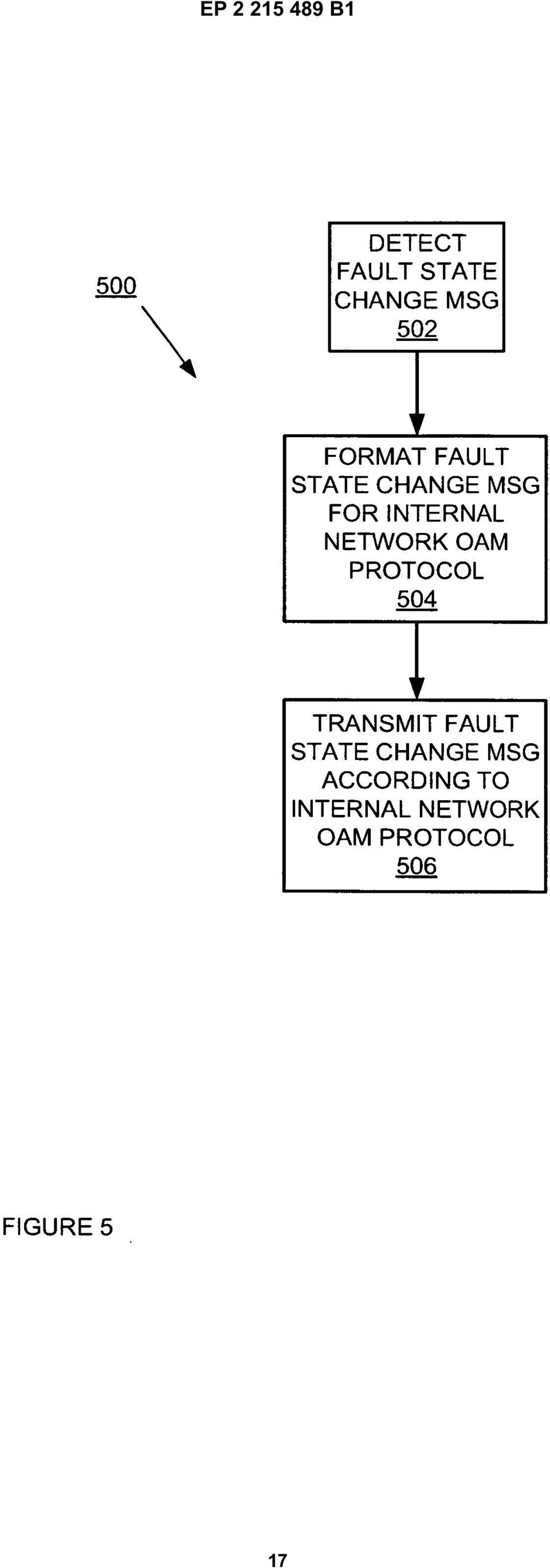
5 7 EP B scribed in reference with Figure 2, block 4. [0027] Returning to Figure 2, connectivity check detection module 8 detects whether fault state change associated with a local MEP. In this embodiment, connectivity check module 8 detects the fault state change by receiving a connectivity check message from a newly active MEP or the lack of a connectivity check message from an active MEP. In one embodiment, connectivity check fault state change module 2 formats a message indicating the fault state change and transmits it to other network elements that are proxying the connectivity check messages. While in one embodiment, this is a VC- CV message carried over the pseudowire between the network elements, in alternate embodiments, other signaling mechanisms in the art can be used. The other network elements use this message to update their remote MEP database and to proxy connectivity check messages to the MEP local to that network element. By sending fault state changes and proxying connectivity check messages, network element 0 provides that end-to-end fault management for MEP without flooding the service provider network interconnecting the two Ethernet networks with constant connectivity checks messages. Furthermore, by detecting local fault state changes of MEP and transmitting these changes to other network elements proxying connectivity check messages, the other network element can automatically build connectivity check databases of remote MEPs. [0028] In reference to Figure 3, network element 4A detects fault state changes in local MEPs 2A-C and transmits faults state change messages to network elements 4B. In this embodiment, network element 4A detects the fault state changes and transmits the appropriate messages as described in reference with Figure 2. [0029] Returning to Figure 2, in one embodiment, connectivity check proxy module 2 transmits the connectivity check messages based on the active MEPs identified in the connectivity check database 6. While in one embodiment, the connectivity check database 6 comprises local and remote MEPs and stores the connectivity status of each MEP in the database, in alternative embodiments, connectivity check database 6 comprise the same and/or different information (e.g., different combinations of active MEPs, local MEPs, remote MEPs, status of MEPs, etc.). [00] Figure 4 is an exemplary flow diagram of a method 0 for proxying connectivity check messages for remote MEPs according to one embodiment of the invention. In one embodiment, network element 0 performs method 0 to proxy connectivity check messages. In Figure 4, at block 2, method 0 receives fault state change messages, indicating a fault state change of a remote MEP. In one embodiment, method 0 receives a VCCV message that indicates the fault state change. [0031] At block 4, method 0 processes the received fault state change message. In one embodiment, method 0 extracts the information from the fault state change message regarding the remote MEP that triggered the fault state change. While in one embodiment, method 0 extracts the MAC address of the remote MEP and whether the remote MEP became active or lost connectivity, in alternate embodiments, method 0 extracts other information such as MEPID, MAC-address, CCinterval, RDI (remote defect indicator) bit. [0032] Method 0 uses the processed information from block 4 to update the connectivity check database at block 6. While in one embodiment, method 0 adds a new entry in the connectivity check database 6 for a remote MEP that becomes active, in alternate embodiments, method 0 can take some other action for a remote MEP that becomes active (update an existing remote MEP entry in connectivity check database 6 to indicate that MEP is active, etc.). In addition, method 0 updates the connectivity check database if the received fault state changes message indicates a remote MEP has lost connectivity. While in one embodiment, method 0 deletes the entry associated with the remote MEP that the message indicated had lost connectivity, in alternate embodiments, method 0 can take some other action (mark that remote MEP as lost connectivity, etc.) [0033] At block 8, method 0 proxies the connectivity check messages by periodically transmitting connectivity check messages to local MEPs based on the updated connectivity check database. In one embodiment, method 0 transmits a connectivity check message for each active remote MEP as indicated in the connectivity check database 6 as described in reference to connectivity check proxy module 2 in Figure 2 and/or network elements 4A-B in Figure 3. [0034] Figure is an exemplary flow diagram of a method 00 for sending VCCV messages to other network elements based on MEP fault state changes according to one embodiment of the invention. In one embodiment, network element 0 performs method 00 to send VCCV messages to other network element based on MEP fault state changes. In Figure, at block 02, method 00 detects a fault state change from one of the local MEPs. [003] At block 04, method 00 formats a fault state change message for the service provider network interconnecting two geographically disperse Ethernet networks. In one embodiment, method 00 formats a fault state change message as a VCCV message sent over one or more of the pseudowires of VPLS network 6. Alternatively, method 00 could format the fault state change message to another suitable OAM protocol for a VPLS network or other type of network interconnecting networks where the MEPs are coupled. In one embodiment, method 00 stores the information about the fault change (source MAC, MEP active, MEP not connected, etc.) in fields of the VCCV message. For example and by way of illustration, a VCCV payload can indicate a message formatted in a way to accommodate multiple CC messages, by using optional and/or custom fields of the VCCV payload. In this way, method 00 transforms fault detection of one protocol (CFM) and carries this in-

6 9 EP B1 formation over another protocol (VCCV, etc.). [0036] At block 06, method 00 transmits the formatted fault state message according to the OAM protocol of the service provider network. While in one embodiment, method 00 transmits the fault state change message according to the VCCV protocol (either in-band or out of band), in alternate embodiments, method 00 transmits the fault state change message according to some other protocol appropriate to the service provider network. [0037] Figure 6 is a block diagram illustrating an exemplary network element 600 that handles proxying connectivity check messages and sending VCCV messages according to one embodiment of the system. In Figure 6, backplane 606 couples to line cards 602A-N and controller cards 604A-B. While in one embodiment, controller cards 604A-B control the processing of the traffic by line cards 602A-N, in alternate embodiments, controller cards 604A-B perform the same and/or different functions (reprogram the line cards, upgrade software, handle operator requests, collect statistics, etc.). Line cards 602A-N process and forward traffic according to the policies received from controller cards 604A-B. In one embodiment, line cards 602A-N proxy connectivity check messages and transmit fault state change messages as described in Figures 2-. [0038] This implementation of the proxy connectivity check messages and transmit fault state change messages is an example, and not by way of limitation. Thus, network elements having other architectural configurations can incorporate embodiments of the invention. Examples of other network elements that could incorporate embodiments of the invention could have multiple line cards or have a single line card. Moreover, a network element having proxy connectivity check messages and transmit fault state change messages distributed across the traffic cards could incorporate embodiments of the invention. [0039] Controller cards 604A-B as well as line cards 602A-N included in the different network elements include memories, processors and/or Application Specific Integrated Circuits (ASICs). Such memory includes a machine-readable medium on which is stored a set of instructions (i.e., software) embodying any one, or all, of the methodologies described herein. Software can reside, completely or at least partially, within this memory and/or within the processor and/or ASICs. For the purposes of this specification, the term "machine-readable medium" shall be taken to include any mechanism that provides (i.e., stores and/or transmits) information in a form readable by a machine (e.g., a computer). For example, a machine-readable medium includes read only memory (ROM); random access memory (RAM); magnetic disk storage media; optical storage media; flash memory devices; etc Alternative Embodiments [00] For example, while the flow diagrams in the figures show a particular order of operations performed by certain embodiments of the invention, it should be understood that such order is exemplary (e.g., alternative embodiments may perform the operations in a different order, combine certain operations, overlap certain operations, etc.) Claims 1. A computerized method in a network element (0, 4), comprising: receiving from another network element (4) a message (VCCV) of a first protocol indicating a fault state change for one of a plurality of remote maintenance endpoints (MEP, 2) coupled to the other network element, the fault state change determined by a second protocol (CFM): updating a local database (6) based on the received message, the local database comprising the fault status of at least some of the plurality of remote maintenance endpoints; and proxying connectivity check messages (CFM, 312, 314) to local maintenance endpoints (2) coupled to the network element based on the updated local database, wherein the proxying comprises periodically sending connectivity check messages (CCM) for each remote maintenance endpoint identified as active in the local database (6). 2. The computerized method of claim 1, wherein each of the proxied connectivity check messages are formatted to appear as if that message originated from one of the plurality of remote maintenance endpoints. 3. The computerized method of claim 1, wherein the updating comprises: storing the fault status of the remote maintenance endpoint associated with the received message. 4. The computerized method of claim 1, wherein the first protocol is the Virtual Circuit Connectivity Verification protocol.. The computerized method of claim 1, wherein the second protocol is the Connectivity Fault Management protocol. 6

7 11 EP B The computerized method of claim 1, wherein each of proxied connectivity check messages comprises an address and a unique identifier of a remote managed endpoint associated with that message. 7. A machine-readable medium that stores instructions, which when executed by a set of one or more processors, cause said set of processors to perform the method steps of one or more of claims An apparatus (0, 4) comprising: a connectivity check state change module (4) to receive from another apparatus one or more messages of a first protocol indicating fault state changes from one or more of a plurality of remote maintenance endpoints (2) coupled to the other apparatus, the fault state change determined by a second protocol; a connectivity check database (6) to store and to update the fault status changes for the one or more of the plurality of remote maintenance endpoints (2); and a connectivity check proxy module (2) to proxy connectivity check messages to local maintenance endpoints coupled to the apparatus based on the database, wherein the proxying comprises periodically sending connectivity check messages for each remote maintenance endpoint identified as active in the local database (6). 9. The apparatus according to claim 8, wherein said apparatus is a network element (600) comprising a controller card (604) that controls functions of the network element and a set of one or more line cards (602), wherein said connectivity check database is a local database, and wherein at least one of the line cards is configured to perform the functions of the connectivity check state change module (4) and the connectivity check proxy module (2) to receive said message of said first protocol indicating a fault state change for one of a plurality of remote maintenance endpoints (2), the fault state change determined by said second protocol; update said local database based on said received message, the local database comprising the fault status of at least some of the plurality of remote maintenance endpoints; and proxy said connectivity check messages to local maintenance endpoints based on the updated local database, wherein the proxying comprises the periodically sending of connectivity check messages for each maintenance endpoint identified as active in the local database.. The apparatus of claim 9, wherein line cards are further configured to: store the fault status change of the remote maintenance endpoint associated with the received message. 11. A computerized method in a network element comprising: Detecting, according to a first protocol (CFM) a fault state change of one of a set of one or more local maintenance endpoints coupled to the network element; creating a fault state change message according to a second protocol, based on the detected fault state change; and sending the fault state change message according to the second protocol to at least one of a plurality of other network elements proxying connectivity check messages to remote maintenance endpoints coupled to the at least one other network element. 12. The computerized method of claim 11, wherein the fault state change indicates a connectivity change for the one of the set of one or more local maintenance endpoints, the change is one of connecting to a network, becoming active on the network, and losing connectivity to the network. 13. The computerized method of claim 11, wherein the first protocol is the Connectivity Fault Management protocol. 14. The computerized method of claim 11, wherein the second protocol is the Virtual Circuit Connectivity Verification protocol. 1. The computerized method of claim 11, wherein information about the fault state change is stored in fields of a VCCV message. 16. The computerized method of claim 11 or 1, wherein a managed endpoint is one of a personal computer, a server, a bridge, and a switch. 17. A machine-readable medium that stores instructions, which when executed by a set of one or more processors, cause said set of processors to perform the method steps of one or more of the method claims An apparatus (0, 4) comprising: a connectivity check detection module (8) to detect, according to a first protocol, a fault state change of one of a set of one or more local maintenance endpoints coupled to the apparatus; and a connectivity check fault state change module 7
 comprising: a connectivity check state change module (4) to receive from another apparatus one or more messages of a first protocol indicating fault state changes from one or more")
8 13 EP B1 14 (2) to create a fault state change message (VCCV) according to a second protocol based on the detected fault state change and send the fault state change message according to the second protocol to at least one of a plurality of other network elements that proxies connectivity check messages to remote maintenance endpoints coupled to the at least one other network element. 19. The apparatus of claim 18, wherein said apparatus is a network element comprising a controller card that controls functions of the network element and a set of one or more line cards, wherein at least one of the line cards is configured to perform the functions of said connectivity check detection module and said connectivity check fault state change module to detect, according to said first protocol, said fault state change of one of a set of one or more local maintenance endpoints, create said fault state change message according to said second protocol based on the detected fault state change, and send the fault state change message according to the second protocol to said at least one of the plurality of other network elements that proxies connectivity check messages. 1 2 jede der Proxy-übermittelten Konnektivitätsprüfnachrichten so formatiert ist, dass sie so erscheint, als wenn diese Nachricht von einem aus der Mehrzahl entfernter Wartungsendpunkte ausgegangen wäre. 3. Computerisiertes Verfahren nach Anspruch 1, wobei das Aktualisieren umfasst: Speichern des Fehlerzustands des mit der empfangenen Nachricht assoziierten entfernten Wartungsendpunkts. 4. Computerisiertes Verfahren nach Anspruch 1, wobei das erste Protokoll das virtuelle Schaltungs-Konnektivitätsverifikationsprotokoll ist.. Computerisiertes Verfahren nach Anspruch 1, wobei das zweite Protokoll das Konnektivitäts-Fehlerverwaltungsprotokoll ist. 6. Computerisiertes Verfahren nach Anspruch 1, wobei jede der Proxy-Konnektivitätsprüfnachrichten eine Adresse und einen eindeutigen Identifikator eines mit dieser Nachricht assoziierten entfernten verwalteten Endpunkts umfasst. Patentansprüche 1. Computerisiertes Verfahren in einem Netzwerkelement (0, 4), umfassend: 7. Maschinen-lesbares Medium, das Anweisungen speichert, die beim Ausführen durch einen Satz eines oder mehrerer Prozessoren den Satz an Prozessoren veranlasst, die Verfahrensschritte eines oder mehrerer der Ansprüche 1 bis 6 durchzuführen. Empfangen, aus einem anderen Netzwerkelement (4), einer Nachricht (VCCV) eines ersten Protokolls, die eine Fehlerzustandsänderung für einen einer Mehrzahl von entfernten Wartungsendpunkten (MEP, 2), die mit dem anderen Netzwerkelement gekoppelt sind, anzeigt, wodurch die Fehlerzustandsänderung durch ein zweites Protokoll (CFM) bestimmt ist; Aktualisieren einer lokalen Datenbank (6), basierend auf der empfangenen Nachricht, wobei die lokale Datenbank den Fehlerzustand zumindest einiger aus der Mehrzahl von entfernten Wartungsendpunkten umfasst; und Proxy-Übermitteln (Proxying) von Konnektivitätsprüfnachrichten (CFM, 312, 314) an lokale Wartungsendpunkte (2), die mit dem Netzwerkelement gekoppelt sind, basierend auf der aktualisierten lokalen Datenbank, wobei das Proxy-Übermitteln periodisches Senden von Konnektivitätsprüfnachrichten (CCM) für jeden entfernten Wartungsendpunkt umfasst, der in der lokalen Datenbank (6) als aktiv identifiziert wurde. 2. Computerisiertes Verfahren nach Anspruch 1, wobei Vorrichtung (0, 4), umfassend: ein Konnektivitäts-Prüfzustandsänderungsmodul (4) zum Empfangen, aus einer anderen Vorrichtung, einer oder mehrerer Nachrichten eines ersten Protokolls, die Fehlerzustandsänderungen aus einer oder mehrerer einer Mehrzahl von entfernten Wartungsendpunkten (2) anzeigen, die mit der anderen Vorrichtung gekoppelt sind, wobei die Fehlerzustandsänderung durch ein zweites Protokoll bestimmt ist; eine Konnektivitäts-Prüfdatenbank (6) zum Speichern und zum Aktualisieren der Fehlerzustandsänderungen für den einen oder mehrere der Mehrzahl von entfernten Wartungsendpunkten (2); und ein Konnektivitäts-Prüfproxymodul (2) zum Proxy-Übermitteln von Konnektivitäts-Prüfnachrichten an lokale Wartungsendpunkte, die mit der Vorrichtung gekoppelt sind, basierend auf der Datenbank, wobei das Proxy-Übermitteln das periodische Senden von Konnektivitäts- Prüfnachrichten für jeden als in der lokalen Datenbank (6) aktiv identifizierten entfernten Wartungsendpunkt umfasst. 8

9 1 EP B Vorrichtung gemäß Anspruch 8, wobei die Vorrichtung ein Netzwerkelement (600) ist, das eine Steuervorrichtungsplatine (604), welche Funktionen des Netzwerkelements steuert, und eine Satz einer oder mehrerer Leitungsplatinen (602) umfasst, wobei die Konnektivitäts-Prüfdatenbank eine lokale Datenbank ist und wobei zumindest eine der Leitungsplatinen konfiguriert ist, die Funktionen des Konnektivitäts-Prüfzustandsänderungsmoduls (4) und des Konnektivitäts-Prüfproxymoduls (2) durchzuführen, um die Nachricht des ersten Protokolls zu empfangen, das eine Fehlerzustandsänderung für einen einer Mehrzahl von entfernten Wartungsendpunkten (2) anzeigt, wobei die Fehlerzustandsänderung durch das zweite Protokoll bestimmt ist; die lokale Datenbank zu aktualisieren, basierend auf der empfangenen Nachricht, wobei die lokale Datenbank den Fehlerstatus zumindest einiger der Mehrzahl entfernter Wartungsendpunkte umfasst; und die Konnektivitäts-Prüfnachrichten an lokale Wartungsendpunkte zu Proxy-Übermitteln, basierend auf der aktualisierten lokalen Datenbank, wobei das Proxy-Übermitteln das periodische Senden von Konnektivitäts-Prüfnachrichten für jeden in der lokalen Datenbank als aktiv identifizierten Wartungsendpunkte umfasst.. Vorrichtung nach Anspruch 9, wobei Leitungsplatinen weiter konfiguriert sind: die Fehlerzustandsänderung des mit der empfangenen Nachricht assoziierten entfernten Wartungsendpunkts zu speichern. 11. Computerisiertes Verfahren in einem Netzwerkelement, umfassend: Detektieren, gemäß einem ersten Protokoll (CFM), einer Fehlerzustandsänderung eines aus einem Satz von einem oder mehreren lokalen Wartungsendpunkten, welche mit dem Netzwerkelement gekoppelt sind; Erzeugen einer Fehlerzustandsänderungsnachricht gemäß einem zweiten Protokoll, basierend auf der detektierten Fehlerzustandsänderung; und Senden der Fehlerzustandsänderungsnachricht gemäß dem zweiten Protokoll an zumindest eines einer Mehrzahl anderer Netzwerkelemente, die Konnektivitäts-Prüfnachrichten an mit dem zumindest einen anderen Netzwerkelement gekoppelte entfernte Wartungsendpunkte Proxy-Übermittelt. 12. Computerisiertes Verfahren nach Anspruch 11, wobei die Fehlerzustandsänderung eine Konnektivitätsänderung für den einen des Satzes eines oder mehrerer lokaler Wartungsendpunkte anzeigt, wobei die Änderung ein Verbinden mit einem Netzwerk, ein im Netzwerk aktiv werden, oder ein Verlieren der Konnektivität mit dem Netzwerk ist. 13. Computerisiertes Verfahren nach Anspruch 11, wobei das erste Protokoll das Konnektivitäts-Fehlerverwaltungsprotokoll ist. 14. Computerisiertes Verfahren nach Anspruch 11, wobei das zweite Protokoll das virtuelle Schaltungs- Konnektivitäts-Verifikationsprotokoll ist. 1. Computerisiertes Verfahren nach Anspruch 11, wobei Informationen zur Fehlerzustandsänderung in Feldern einer VCCV-Nachricht gespeichert sind. 16. Computerisiertes Verfahren nach Anspruch 11 oder 1, wobei ein verwalteter Endpunkt ein Persönlicher Computer, ein Server, eine Brückenvorrichtung (Bridge) oder eine Durchschaltvorrichtung (Switch) ist. 17. Maschinen-lesbares Medium, das Anweisungen speichert, die beim Ausführen durch einen Satz eines oder mehrerer Prozessoren den Satz von Prozessoren veranlassen, die Verfahrensschritte eines oder mehrerer der Verfahrensansprüche 11 bis 16 durchzuführen. 18. Vorrichtung (0, 4), umfassend: ein Konnektivitäts-Prüfmodul (8) zum Detektieren, gemäß einem ersten Protokoll, einer Fehlerzustandsänderung eines aus einem Satz von mit der Vorrichtung gekoppelten einen oder mehreren lokalen Wartungsendpunkten; und ein Konnektivitäts-Prüffehlerzustandsänderungsmodul (2) zum Erzeugen einer Fehlerzustandsänderungsnachricht (VCCV) gemäß einem zweiten Protokoll, basierend auf der detektierten Fehlerzustandsänderung, und Senden der Fehlerzustandsänderungsnachricht gemäß dem zweiten Protokoll an zumindest eines einer Mehrzahl von anderen Netzwerkelementen, das Konnektivitäts-Prüfnachrichten an entfernte Wartungsendpunkte Proxy-Übermittelt, die mit dem zumindest einen anderen Netzwerkelement gekoppelt sind. 19. Vorrichtung nach Anspruch 18, wobei die Vorrichtung ein Netzwerkelement ist, das eine Steuervorrichtungsplatine, welche Funktionen des Netzwerkelements steuert, und einen Satz einer oder mehrerer Leitungsplatinen umfasst, wobei die zumindest eine der Leitungsplatinen konfiguriert ist, die Funktionen des Konnektivitäts-Prüfdetektionsmoduls und des Konnektivitäts-Prüffeh- 9
 und des Konnektivitäts-Prüfproxymoduls (2) durchzuführen, um die Nachricht des ersten Protokolls zu empfangen, das eine Fehlerzustandsänderung für einen")
10 17 EP B1 18 lerzustandsänderungsmoduls durchzuführen, um gemäß dem ersten Protokoll die Fehlerzustandsänderung eines aus einem Satz von einem oder mehreren lokalen Wartungsendpunkten zu detektieren, die Fehlerzustandsänderungsnachricht gemäß dem zweiten Protokoll zu erzeugen, basierend auf der detektierten Fehlerzustandsänderung, und die Fehlerzustandsänderungsnachricht gemäß dem zweiten Protokoll an das zumindest eine der Mehrzahl von anderen Netzwerkelementen zu senden, das Konnektivitäts-Prüfnachrichten Proxy-Übermittelt. Revendications 1. Procédé informatisé dans un élément réseau (0, 4), comprenant le fait : de recevoir d un autre élément réseau (4) un message (VCCV) d un premier protocole indiquant un changement d état de défaut pour l un d une pluralité de points d extrémité de télémaintenance (MEP, 2) couplés à l autre élément réseau, le changement d état de défaut étant déterminé par un deuxième protocole (CFM) : de mettre à jour une base de données locale (6) sur la base du message reçu, la base de données locale comprenant les états de défaut d au moins une partie de la pluralité de points d extrémité de télémaintenance ; et de mandater des messages de vérification de connectivité (CFM, 312, 314) à des points d extrémité locaux de maintenance (2) couplés à l élément réseau sur la base de la base de données locale mise à jour, où le fait de mandater comprend l envoi périodique des messages de vérification de connectivité (CCM) pour chaque point d extrémité de télémaintenance identifié comme étant actif dans la base de données locale (6). 2. Procédé informatisé de la revendication 1, dans lequel chacun des messages de vérification de connectivité mandaté est formaté pour apparaître comme s il provenait de l un de la pluralité de points d extrémité de télémaintenance. 3. Procédé informatisé de la revendication 1, dans lequel la mise à jour comprend le fait : de stocker les états de défaut du point d extrémité de télémaintenance associé au message reçu Procédé informatisé de la revendication 1, dans lequel le premier protocole est le protocole de Vérification de Connectivité des Circuits Virtuels.. Procédé informatisé de la revendication 1, dans lequel le deuxième protocole est le protocole de Gestion des Défauts de Connectivité. 6. Procédé informatisé de la revendication 1, dans lequel chacun des messages de vérification de connectivité mandaté comprend une adresse et un identifiant unique d un point d extrémité géré à distance associé à ce message. 7. Support lisible par machine qui stocke des instructions, qui lorsqu elles sont exécutées par un ensemble d un ou de plusieurs processeurs, amènent ledit ensemble de processeurs à mettre en oeuvre les étapes du procédé de l une ou de plusieurs des revendications 1 à Appareil (0, 4) comprenant : un module de changement d état de vérification de connectivité (4) destiné à recevoir d un autre appareil un ou plusieurs messages d un premier protocole indiquant les changements d état de défaut d un ou de plusieurs d une pluralité de points d extrémité de télémaintenance (2) couplés à l autre appareil, le changement d état de défaut déterminé par un deuxième protocole ; une base de données de vérification de connectivité (6) destinée à stocker et à mettre à jour les changements des états de défaut pour un ou plusieurs points de la pluralité de points d extrémité de télémaintenance (2) ; et un module mandataire de vérification de connectivité (2) destiné à mandater des messages de vérification de connectivité aux points d extrémité locaux de maintenance couplés à l appareil sur la base de la base de données, où le fait de mandater comprend l envoi périodique des messages de vérification de connectivité pour chaque point d extrémité de télémaintenance identifié comme étant actif dans la base de données locale (6). 9. Appareil selon la revendication 8, dans lequel ledit appareil est un élément réseau (600) comprenant une carte de commande (604) qui commande des fonctions de l élément réseau et un ensemble d une ou de plusieurs cartes de lignes (602), où ladite base de données de vérification de connectivité est une base de données locale, et où au moins l une des cartes de lignes est configurée pour exécuter les fonctions du module de changement d état de vérification de connectivité (4) et le module manda-
, comprenant le fait : de recevoir d un autre élément réseau (4) un message (VCCV) d un premier protocole indiquant un changement d état de défaut")
11 19 EP B1 taire de vérification de connectivité (2) pour recevoir ledit message dudit premier protocole indiquant un changement d état de défaut de l un d une pluralité de points d extrémité de télémaintenance (2), le changement d état de défaut étant déterminé par ledit deuxième protocole ; pour mettre à jour ladite base de données locale sur la base dudit message reçu, la base de données locale comprenant les états de défaut d au moins certains de la pluralité de points d extrémité de télémaintenance ; et pour mandater lesdits messages de vérification de connectivité aux points d extrémité locaux de maintenance sur la base de la base de données locale mise à jour, où le fait de mandater comprend l envoi périodique des messages de vérification de connectivité pour chaque point d extrémité de maintenance identifié comme étant actif dans la base de données locale.. Appareil de la revendication 9, dans lequel les cartes de lignes sont en outre configurées pour stocker le changement des états de défaut du point d extrémité de télémaintenance associé au message reçu. 11. Procédé informatisé dans un élément réseau comprenant le fait : de détecter, selon un premier protocole (CFM), un changement d état de défaut de l un d un ensemble d un ou de plusieurs points d extrémité locaux de maintenance couplé(s) à l élément réseau ; de créer un message de changement d état de défaut selon un deuxième protocole, sur la base du changement d état de défaut détecté ; et d envoyer le message de changement d état de défaut selon le deuxième protocole à au moins l un d une pluralité d autres éléments réseau mandatant les messages de vérification de connectivité aux points d extrémité de télémaintenance couplés à l au moins un autre élément réseau. 12. Procédé informatisé de la revendication 11, dans lequel le changement d état de défaut indique un changement de connectivité pour l un de l ensemble d un ou de plusieurs points d extrémité locaux de maintenance, le changement est l un parmi la connexion à un réseau, devenir actif sur le réseau, et perdre la connectivité au réseau. 13. Procédé informatisé de la revendication 11, dans lequel le premier protocole est le protocole de Gestion des Défauts de Connectivité Procédé informatisé de la revendication 11, dans lequel le deuxième protocole est le protocole de Vérification de Connectivité des Circuits Virtuels. 1. Procédé informatisé de la revendication 11, dans lequel des informations concernant le changement d état de défaut sont stockées dans des champs d un message VCCV. 16. Procédé informatisé de la revendication 11 ou 1, dans lequel un point d extrémité géré est l un d un ordinateur personnel, d un serveur, d un pont et d un commutateur. 17. Support lisible par machine qui stocke des instructions, qui lorsqu elles sont exécutées par un ensemble d un ou de plusieurs processeurs, amènent ledit ensemble de processeurs à mettre en oeuvre les étapes du procédé de l une ou de plusieurs des revendications du procédé 11 à Appareil (0, 4) comprenant : un module de détection de vérification de connectivité (8) destiné à détecter, selon un premier protocole, un changement d état de défaut de l un d un ensemble d un ou de plusieurs points d extrémité locaux de maintenance couplé(s) à l appareil ; et un module de changement d état de défaut de vérification de connectivité (2) destiné à créer un message de changement d état de défaut (VCCV) selon un deuxième protocole sur la base du changement d état de défaut détecté et à envoyer le message de changement d état de défaut selon le deuxième protocole à au moins l un d une pluralité d autres éléments réseau qui mandate des messages de vérification de connectivité à des points d extrémité de télémaintenance couplés à l au moins un autre élément réseau. 19. Appareil de la revendication 18, dans lequel ledit appareil est un élément réseau comprenant une carte de commande qui commande des fonctions de l élément réseau et un ensemble d une ou de plusieurs cartes de lignes, où au moins l une des cartes de lignes est configurée pour exécuter les fonctions dudit module de détection de vérification de connectivité et dudit module de changement d état de défaut de vérification de connectivité pour détecter, selon ledit premier protocole, ledit changement d état de défaut de l un d un ensemble d un ou de plusieurs points d extrémité locaux de maintenance, pour créer ledit message de changement d état de défaut selon ledit deuxième protocole sur la base du changement d état de défaut détecté, et pour envoyer le message de changement d état de défaut 11

12 21 EP B1 22 selon le deuxième protocole audit au moins un de la pluralité d autres éléments réseau qui mandate les messages de vérification de connectivité

13 EP B1 13

14 EP B1 14

15 EP B1 1

16 EP B1 16

17 EP B1 17
18 EP B1 18

19 EP B1 REFERENCES CITED IN THE DESCRIPTION This list of references cited by the applicant is for the reader s convenience only. It does not form part of the European patent document. Even though great care has been taken in compiling the references, errors or omissions cannot be excluded and the EPO disclaims all liability in this regard. Patent documents cited in the description US A1 [0007] 19

Titelbild1 ANSYS. Customer Portal LogIn
 Titelbild1 ANSYS Customer Portal LogIn 1 Neuanmeldung Neuanmeldung: Bitte Not yet a member anklicken Adressen-Check Adressdaten eintragen Customer No. ist hier bereits erforderlich HERE - Button Hier nochmal
Formatting the TrekStor i.beat run
 DE EN Formatting the TrekStor i.beat run Formatierung des TrekStor i.beat run a Beim Formatieren werden ALLE Daten auf dem MP3-Player gelöscht. In diesem Abschnitt wird Ihnen erläutert, wie Sie Ihren MP3-Player
p^db=`oj===pìééçêíáåñçêã~íáçå=
 p^db=`oj===pìééçêíáåñçêã~íáçå= Error: "Could not connect to the SQL Server Instance" or "Failed to open a connection to the database." When you attempt to launch ACT! by Sage or ACT by Sage Premium for
Softwareupdate-Anleitung // AC Porty L Netzteileinschub
 1 Softwareupdate-Anleitung // AC Porty L Netzteileinschub Softwareupdate-Anleitung // AC Porty L Netzteileinschub HENSEL-VISIT GmbH & Co. KG Robert-Bunsen-Str. 3 D-97076 Würzburg-Lengfeld GERMANY Tel./Phone:
DPM_flowcharts.doc Page F-1 of 9 Rüdiger Siol :28
 Contents F TOOLS TO SUPPORT THE DOCUMENTATION... F-2 F.1 GRAPHIC SYMBOLS AND THEIR APPLICATION (DIN 66 001)... F-2 F.1.1 Flow of control... F-3 F.1.2 Terminators and connectors... F-4 F.1.3 Lines, arrows
(51) Int Cl.: H04L 29/12 (2006.01) H04L 12/28 (2006.01)
 Int Cl.: H04L 29/12 (2006.01) H04L 12/28 (2006.01)") (19) TEPZZ_89 9 8B_T (11) EP 1 892 928 B1 (12) EUROPEAN PATENT SPECIFICATION (4) Date of publication and mention of the grant of the patent: 18.03.1 Bulletin 1/12 (1) Int Cl.: H04L 29/12 (06.01) H04L 12/28
(19) TEPZZ_89 9 8B_T (11) EP 1 892 928 B1 (12) EUROPEAN PATENT SPECIFICATION (4) Date of publication and mention of the grant of the patent: 18.03.1 Bulletin 1/12 (1) Int Cl.: H04L 29/12 (06.01) H04L 12/28
VGM. VGM information. HAMBURG SÜD VGM WEB PORTAL USER GUIDE June 2016
 Overview The Hamburg Süd VGM Web portal is an application that enables you to submit VGM information directly to Hamburg Süd via our e-portal Web page. You can choose to enter VGM information directly,
miditech 4merge 4-fach MIDI Merger mit :
 miditech 4merge 4-fach MIDI Merger mit : 4 x MIDI Input Port, 4 LEDs für MIDI In Signale 1 x MIDI Output Port MIDI USB Port, auch für USB Power Adapter Power LED und LOGO LEDs Hochwertiges Aluminium Gehäuse
TEPZZ Z4Z4 4B_T EP B1 (19) (11) EP B1 (12) EUROPEAN PATENT SPECIFICATION
 (11) EP B1 (12) EUROPEAN PATENT SPECIFICATION") (19) TEPZZ Z4Z4 4B_T (11) EP 2 0 424 B1 (12) EUROPEAN PATENT SPECIFICATION (4) Date of publication and mention of the grant of the patent:.07.14 Bulletin 14/31 (21) Application number: 08168678.4 (1) Int
(19) TEPZZ Z4Z4 4B_T (11) EP 2 0 424 B1 (12) EUROPEAN PATENT SPECIFICATION (4) Date of publication and mention of the grant of the patent:.07.14 Bulletin 14/31 (21) Application number: 08168678.4 (1) Int
Kurzanleitung um Transponder mit einem scemtec TT Reader und der Software UniDemo zu lesen
 Kurzanleitung um Transponder mit einem scemtec TT Reader und der Software UniDemo zu lesen QuickStart Guide to read a transponder with a scemtec TT reader and software UniDemo Voraussetzung: - PC mit der
prorm Budget Planning promx GmbH Nordring Nuremberg
 prorm Budget Planning Budget Planning Business promx GmbH Nordring 100 909 Nuremberg E-Mail: support@promx.net Content WHAT IS THE prorm BUDGET PLANNING? prorm Budget Planning Overview THE ADVANTAGES OF
NEWSLETTER. FileDirector Version 2.5 Novelties. Filing system designer. Filing system in WinClient
 Filing system designer FileDirector Version 2.5 Novelties FileDirector offers an easy way to design the filing system in WinClient. The filing system provides an Explorer-like structure in WinClient. The
Word-CRM-Upload-Button. User manual
 Word-CRM-Upload-Button User manual Word-CRM-Upload for MS CRM 2011 Content 1. Preface... 3 2. Installation... 4 2.1. Requirements... 4 2.1.1. Clients... 4 2.2. Installation guidelines... 5 2.2.1. Client...
Parameter-Updatesoftware PF-12 Plus
 Parameter-Updatesoftware PF-12 Plus Mai / May 2015 Inhalt 1. Durchführung des Parameter-Updates... 2 2. Kontakt... 6 Content 1. Performance of the parameter-update... 4 2. Contact... 6 1. Durchführung
Exercise (Part II) Anastasia Mochalova, Lehrstuhl für ABWL und Wirtschaftsinformatik, Kath. Universität Eichstätt-Ingolstadt 1
 Anastasia Mochalova, Lehrstuhl für ABWL und Wirtschaftsinformatik, Kath. Universität Eichstätt-Ingolstadt 1") Exercise (Part II) Notes: The exercise is based on Microsoft Dynamics CRM Online. For all screenshots: Copyright Microsoft Corporation. The sign ## is you personal number to be used in all exercises. All
Exercise (Part II) Notes: The exercise is based on Microsoft Dynamics CRM Online. For all screenshots: Copyright Microsoft Corporation. The sign ## is you personal number to be used in all exercises. All
KURZANLEITUNG. Firmware-Upgrade: Wie geht das eigentlich?
 KURZANLEITUNG Firmware-Upgrade: Wie geht das eigentlich? Die Firmware ist eine Software, die auf der IP-Kamera installiert ist und alle Funktionen des Gerätes steuert. Nach dem Firmware-Update stehen Ihnen
Customer-specific software for autonomous driving and driver assistance (ADAS)
") This press release is approved for publication. Press Release Chemnitz, February 6 th, 2014 Customer-specific software for autonomous driving and driver assistance (ADAS) With the new product line Baselabs
This press release is approved for publication. Press Release Chemnitz, February 6 th, 2014 Customer-specific software for autonomous driving and driver assistance (ADAS) With the new product line Baselabs
EEX Kundeninformation 2007-09-05
 EEX Eurex Release 10.0: Dokumentation Windows Server 2003 auf Workstations; Windows Server 2003 Service Pack 2: Information bezüglich Support Sehr geehrte Handelsteilnehmer, Im Rahmen von Eurex Release
(51) Int Cl. 7 : H04L 29/12
 Int Cl. 7 : H04L 29/12") (19) Europäisches Patentamt European Patent Office Office européen des brevets *EP0017027B1* (11) EP 1 7 027 B1 (12) EUROPEAN PATENT SPECIFICATION (4) Date of publication and mention of the grant of the
(19) Europäisches Patentamt European Patent Office Office européen des brevets *EP0017027B1* (11) EP 1 7 027 B1 (12) EUROPEAN PATENT SPECIFICATION (4) Date of publication and mention of the grant of the
Analysis Add-On Data Lineage
 1 Analysis Add-On Data Lineage Docu Performer Analysis Add-On Data Lineage 2 Introduction... 3 Starting the Function... 4 Display of the Mapping in Excel... 5 BW InfoProvider... 6 HANA Objects... 7 ABAP
CABLE TESTER. Manual DN-14003
 CABLE TESTER Manual DN-14003 Note: Please read and learn safety instructions before use or maintain the equipment This cable tester can t test any electrified product. 9V reduplicated battery is used in
VGM. VGM information. HAMBURG SÜD VGM WEB PORTAL - USER GUIDE June 2016
 Overview The Hamburg Süd VGM-Portal is an application which enables to submit VGM information directly to Hamburg Süd via our e-portal web page. You can choose to insert VGM information directly, or download
Tube Analyzer LogViewer 2.3
 Tube Analyzer LogViewer 2.3 User Manual Stand: 25.9.2015 Seite 1 von 11 Name Company Date Designed by WKS 28.02.2013 1 st Checker 2 nd Checker Version history Version Author Changes Date 1.0 Created 19.06.2015
Infrastructure as a Service (IaaS) Solutions for Online Game Service Provision
 Solutions for Online Game Service Provision") Infrastructure as a Service (IaaS) Solutions for Online Game Service Provision Zielsetzung: System Verwendung von Cloud-Systemen für das Hosting von online Spielen (IaaS) Reservieren/Buchen von Resources
Infrastructure as a Service (IaaS) Solutions for Online Game Service Provision Zielsetzung: System Verwendung von Cloud-Systemen für das Hosting von online Spielen (IaaS) Reservieren/Buchen von Resources
https://portal.microsoftonline.com
 Sie haben nun Office über Office365 bezogen. Ihr Account wird in Kürze in dem Office365 Portal angelegt. Anschließend können Sie, wie unten beschrieben, die Software beziehen. Congratulations, you have
The Single Point Entry Computer for the Dry End
 The Single Point Entry Computer for the Dry End The master computer system was developed to optimize the production process of a corrugator. All entries are made at the master computer thus error sources
TEPZZ 749 B_T EP 2 274 932 B1 (19) (11) EP 2 274 932 B1 (12) EUROPEAN PATENT SPECIFICATION
 (11) EP 2 274 932 B1 (12) EUROPEAN PATENT SPECIFICATION") (19) TEPZZ 749 B_T (11) EP 2 274 932 B1 (12) EUROPEAN PATENT SPECIFICATION (4) Date of publication and mention of the grant of the patent: 2.02.1 Bulletin 1/09 (21) Application number: 0870229.0 (22) Date
(19) TEPZZ 749 B_T (11) EP 2 274 932 B1 (12) EUROPEAN PATENT SPECIFICATION (4) Date of publication and mention of the grant of the patent: 2.02.1 Bulletin 1/09 (21) Application number: 0870229.0 (22) Date
Aufbau eines IT-Servicekataloges am Fallbeispiel einer Schweizer Bank
 SwissICT 2011 am Fallbeispiel einer Schweizer Bank Fritz Kleiner, fritz.kleiner@futureways.ch future ways Agenda Begriffsklärung Funktionen und Aspekte eines IT-Servicekataloges Fallbeispiel eines IT-Servicekataloges
Microsoft Azure Fundamentals MOC 10979
 Microsoft Azure Fundamentals MOC 10979 In dem Kurs Microsoft Azure Fundamentals (MOC 10979) erhalten Sie praktische Anleitungen und Praxiserfahrung in der Implementierung von Microsoft Azure. Ihnen werden
1. General information... 2 2. Login... 2 3. Home... 3 4. Current applications... 3
 User Manual for Marketing Authorisation and Lifecycle Management of Medicines Inhalt: User Manual for Marketing Authorisation and Lifecycle Management of Medicines... 1 1. General information... 2 2. Login...
Electrical tests on Bosch unit injectors
 Valid for Bosch unit injectors with order numbers 0 414 700 / 0 414 701 / 0 414 702 Parts Kit Magnet*: - F00H.N37.925 - F00H.N37.933 - F00H.N37.934 * For allocation to the 10-place Bosch order number,
(51) Int Cl.: H04L 12/28 (2006.01) H04L 29/06 (2006.01)
 Int Cl.: H04L 12/28 (2006.01) H04L 29/06 (2006.01)") (19) Europäisches Patentamt European Patent Office Office européen des brevets (12) EUROPEAN PATENT SPECIFICATION (11) EP 1 382 161 B1 (4) Date of publication and mention of the grant of the patent: 04.01.06
(19) Europäisches Patentamt European Patent Office Office européen des brevets (12) EUROPEAN PATENT SPECIFICATION (11) EP 1 382 161 B1 (4) Date of publication and mention of the grant of the patent: 04.01.06
vcdm im Wandel Vorstellung des neuen User Interfaces und Austausch zur Funktionalität V
 vcdm im Wandel Vorstellung des neuen User Interfaces und Austausch zur Funktionalität V0.1 2018-10-02 Agenda vcdm User Interface History Current state of User Interface User Interface X-mas 2018 Missing
Mitglied der Leibniz-Gemeinschaft
 Methods of research into dictionary use: online questionnaires Annette Klosa (Institut für Deutsche Sprache, Mannheim) 5. Arbeitstreffen Netzwerk Internetlexikografie, Leiden, 25./26. März 2013 Content
Ein Stern in dunkler Nacht Die schoensten Weihnachtsgeschichten. Click here if your download doesn"t start automatically
 Ein Stern in dunkler Nacht Die schoensten Weihnachtsgeschichten Click here if your download doesn"t start automatically Ein Stern in dunkler Nacht Die schoensten Weihnachtsgeschichten Ein Stern in dunkler
Communications & Networking Accessories
 3Com10 Mbit (Combo) 3Com world leading in network technologies is a strategic partner of Fujitsu Siemens Computers. Therefore it is possible for Fujitsu Siemens Computers to offer the very latest in mobile
Newest Generation of the BS2 Corrosion/Warning and Measurement System
 Newest Generation of the BS2 Corrosion/Warning and Measurement System BS2 System Description: BS2 CorroDec 2G is a cable and energyless system module range for detecting corrosion, humidity and prevailing
Where are we now? The administration building M 3. Voransicht
 Let me show you around 9 von 26 Where are we now? The administration building M 3 12 von 26 Let me show you around Presenting your company 2 I M 5 Prepositions of place and movement There are many prepositions
(51) Int Cl.: H04L 12/26 (2006.01) (56) References cited:
 Int Cl.: H04L 12/26 (2006.01) (56) References cited:") (19) (12) EUROPEAN PATENT SPECIFICATION (11) EP 1 819 097 B1 (4) Date of publication and mention of the grant of the patent: 17.06.09 Bulletin 09/2 (21) Application number: 0673143.4 (22) Date of filing:
(19) (12) EUROPEAN PATENT SPECIFICATION (11) EP 1 819 097 B1 (4) Date of publication and mention of the grant of the patent: 17.06.09 Bulletin 09/2 (21) Application number: 0673143.4 (22) Date of filing:
RS232-Verbindung, RXU10 Herstellen einer RS232-Verbindung zwischen PC und Messgerät oder Modem und Messgerät
 Betriebsanleitung RS232-Verbindung, RXU10 Herstellen einer RS232-Verbindung zwischen PC und Messgerät oder Modem und Messgerät ä 2 Operating Instructions RS232 Connection, RXU10 Setting up an RS232 connection
4.) Geben Sie im Feld Adresse die IP Adresse des TDC Controllers ein. Die Standard Adresse lautet 192.168.1.50.
 Geben Sie im Feld Adresse die IP Adresse des TDC Controllers ein. Die Standard Adresse lautet 192.168.1.50.") Netzwerk: 1.) Kopieren Sie die Datei C30remote.exe von der Installations CD auf ihre Festplatte. 2.) Starten Sie die Datei C30remote.exe auf ihrer Festplatte. 3.) Wählen Sie aus dem Menü Verbindung den
Netzwerk: 1.) Kopieren Sie die Datei C30remote.exe von der Installations CD auf ihre Festplatte. 2.) Starten Sie die Datei C30remote.exe auf ihrer Festplatte. 3.) Wählen Sie aus dem Menü Verbindung den
Der Adapter Z250I / Z270I lässt sich auf folgenden Betriebssystemen installieren:
 Installationshinweise Z250I / Z270I Adapter IR USB Installation hints Z250I / Z270I Adapter IR USB 06/07 (Laden Sie den Treiber vom WEB, entpacken Sie ihn in ein leeres Verzeichnis und geben Sie dieses
HIR Method & Tools for Fit Gap analysis
 HIR Method & Tools for Fit Gap analysis Based on a Powermax APML example 1 Base for all: The Processes HIR-Method for Template Checks, Fit Gap-Analysis, Change-, Quality- & Risk- Management etc. Main processes
ecall sms & fax-portal
 ecall sms & fax-portal Beschreibung des s Dateiname Beschreibung_-_eCall 2015.08.04 Version 1.1 Datum 04.08.2015 Dolphin Systems AG Informieren & Alarmieren Samstagernstrasse 45 CH-8832 Wollerau Tel. +41
TomTom WEBFLEET Tachograph
 TomTom WEBFLEET Tachograph Installation TG, 17.06.2013 Terms & Conditions Customers can sign-up for WEBFLEET Tachograph Management using the additional services form. Remote download Price: NAT: 9,90.-/EU:
Hinweisblatt. Für den Einsatz des MAX! Heizungssteuerungssystems haben Sie zwei Alternativen: Die MAX! Einzelraumlösung und die MAX! Hauslösung.
 Hinweisblatt MAX! Heizkörperthermostat BC-RT-TRX-CyG Art.-Nr. 99017 MAX! Fensterkontakt BC-SC-Rd-WM Art.-Nr. 99023 Für den Einsatz des MAX! Heizungssteuerungssystems haben Sie zwei Alternativen: Die MAX!
Level 2 German, 2015
 91126 911260 2SUPERVISOR S Level 2 German, 2015 91126 Demonstrate understanding of a variety of written and / or visual German text(s) on familiar matters 2.00 p.m. Friday 4 December 2015 Credits: Five
ONLINE LICENCE GENERATOR
 Index Introduction... 2 Change language of the User Interface... 3 Menubar... 4 Sold Software... 5 Explanations of the choices:... 5 Call of a licence:... 7 Last query step... 9 Call multiple licenses:...
ELBA2 ILIAS TOOLS AS SINGLE APPLICATIONS
 ELBA2 ILIAS TOOLS AS SINGLE APPLICATIONS An AAA/Switch cooperative project run by LET, ETH Zurich, and ilub, University of Bern Martin Studer, ilub, University of Bern Julia Kehl, LET, ETH Zurich 1 Contents
IDS Lizenzierung für IDS und HDR. Primärserver IDS Lizenz HDR Lizenz
 IDS Lizenzierung für IDS und HDR Primärserver IDS Lizenz HDR Lizenz Workgroup V7.3x oder V9.x Required Not Available Primärserver Express V10.0 Workgroup V10.0 Enterprise V7.3x, V9.x or V10.0 IDS Lizenz
Preisliste für The Unscrambler X
 Preisliste für The Unscrambler X english version Alle Preise verstehen sich netto zuzüglich gesetzlicher Mehrwertsteuer (19%). Irrtümer, Änderungen und Fehler sind vorbehalten. The Unscrambler wird mit
1.1 VoIP - Kein Notruf möglich. 1.2 VoIP - Vorrang von Notrufen
 Read Me System Software 9.1.10 Patch 4 PED/BED Deutsch Folgende Fehler sind in Systemsoftware 9.1.10 Patch 4 korrigiert worden: 1.1 VoIP - Kein Notruf möglich (ID 19307) In bestimmten Konfigurationen konnte
Exercise (Part V) Anastasia Mochalova, Lehrstuhl für ABWL und Wirtschaftsinformatik, Kath. Universität Eichstätt-Ingolstadt 1
 Anastasia Mochalova, Lehrstuhl für ABWL und Wirtschaftsinformatik, Kath. Universität Eichstätt-Ingolstadt 1") Exercise (Part V) Notes: The exercise is based on Microsoft Dynamics CRM Online. For all screenshots: Copyright Microsoft Corporation. The sign ## is you personal number to be used in all exercises. All
Exercise (Part V) Notes: The exercise is based on Microsoft Dynamics CRM Online. For all screenshots: Copyright Microsoft Corporation. The sign ## is you personal number to be used in all exercises. All
(51) Int Cl.: G09G 5/12 (2006.01) H04N 21/485 (2011.01)
 Int Cl.: G09G 5/12 (2006.01) H04N 21/485 (2011.01)") (19) TEPZZ_66 475B_T (11) EP 1 662 475 B1 (12) EUROPEAN PATENT SPECIFICATION (45) Date of publication and mention of the grant of the patent: 11.03.2015 Bulletin 2015/11 (51) Int Cl.: G09G 5/12 (2006.01)
(19) TEPZZ_66 475B_T (11) EP 1 662 475 B1 (12) EUROPEAN PATENT SPECIFICATION (45) Date of publication and mention of the grant of the patent: 11.03.2015 Bulletin 2015/11 (51) Int Cl.: G09G 5/12 (2006.01)
FEBE Die Frontend-Backend-Lösung für Excel
 FEBE Die Frontend--Lösung für FEBE Die Frontend--Lösung für FEBE.pptx 8.04.206 0:43 FEBE Die Frontend--Lösung für Nutzer A alle_aufträge neuer_auftrag Auftragsänderung Nutzer B alle_aufträge neuer_auftrag
iid software tools QuickStartGuide iid USB base driver installation
 iid software tools QuickStartGuide iid software tools USB base driver installation microsensys Nov 2016 Introduction / Einleitung This document describes in short form installation of the microsensys USB
ReadMe zur Installation der BRICKware for Windows, Version 6.1.2. ReadMe on Installing BRICKware for Windows, Version 6.1.2
 ReadMe zur Installation der BRICKware for Windows, Version 6.1.2 Seiten 2-4 ReadMe on Installing BRICKware for Windows, Version 6.1.2 Pages 5/6 BRICKware for Windows ReadMe 1 1 BRICKware for Windows, Version
Wozu dient ein Logikanalysator?
 Wozu dient ein Logikanalysator? Beispiel: Microcontroller Microcontroller kommen vor in Haushaltsgeräten (Waschmaschine,...) in Fahrzeugen (ABS, Motorsteuerung, Radio,...) in Computern (Tastatur, Festplatte,
EP 1 750 416 A1 (19) (11) EP 1 750 416 A1 (12) EUROPÄISCHE PATENTANMELDUNG. (43) Veröffentlichungstag: 07.02.2007 Patentblatt 2007/06
 (11) EP 1 750 416 A1 (12) EUROPÄISCHE PATENTANMELDUNG. (43) Veröffentlichungstag: 07.02.2007 Patentblatt 2007/06") (19) (12) EUROPÄISCHE PATENTANMELDUNG (11) EP 1 750 416 A1 (43) Veröffentlichungstag: 07.02.2007 Patentblatt 2007/06 (51) Int Cl.: H04L 29/12 (2006.01) (21) Anmeldenummer: 05016706.3 (22) Anmeldetag: 01.08.2005
(19) (12) EUROPÄISCHE PATENTANMELDUNG (11) EP 1 750 416 A1 (43) Veröffentlichungstag: 07.02.2007 Patentblatt 2007/06 (51) Int Cl.: H04L 29/12 (2006.01) (21) Anmeldenummer: 05016706.3 (22) Anmeldetag: 01.08.2005
Weather forecast in Accra
 Weather forecast in Accra Thursday Friday Saturday Sunday 30 C 31 C 29 C 28 C f = 9 5 c + 32 Temperature in Fahrenheit Temperature in Celsius 2 Converting Celsius to Fahrenheit f = 9 5 c + 32 tempc = 21
(51) Int Cl.: B23K 26/28 (2014.01) B23K 26/32 (2014.01) B23K 26/30 (2014.01) B23K 33/00 (2006.01)
 Int Cl.: B23K 26/28 (2014.01) B23K 26/32 (2014.01) B23K 26/30 (2014.01) B23K 33/00 (2006.01)") (19) TEPZZ 87_Z ZA_T (11) EP 2 871 0 A1 (12) EUROPÄISCHE PATENTANMELDUNG (43) Veröffentlichungstag: 13.0.1 Patentblatt 1/ (21) Anmeldenummer: 13192326.0 (1) Int Cl.: B23K 26/28 (14.01) B23K 26/32 (14.01)
(19) TEPZZ 87_Z ZA_T (11) EP 2 871 0 A1 (12) EUROPÄISCHE PATENTANMELDUNG (43) Veröffentlichungstag: 13.0.1 Patentblatt 1/ (21) Anmeldenummer: 13192326.0 (1) Int Cl.: B23K 26/28 (14.01) B23K 26/32 (14.01)
(74) Representative: Boyce, Conor et al F. R. Kelly & Co., 27 Clyde Road, Ballsbridge Dublin 4 (IE)
 Representative: Boyce, Conor et al F. R. Kelly & Co., 27 Clyde Road, Ballsbridge Dublin 4 (IE)") (19) Europäisches Patentamt European Patent Office Office européen des brevets *EP00867B1* (11) EP 1 086 7 B1 (12) EUROPEAN PATENT SPECIFICATION (4) Date of publication and mention of the grant of the
(19) Europäisches Patentamt European Patent Office Office européen des brevets *EP00867B1* (11) EP 1 086 7 B1 (12) EUROPEAN PATENT SPECIFICATION (4) Date of publication and mention of the grant of the
Order Ansicht Inhalt
 Order Ansicht Inhalt Order Ansicht... 1 Inhalt... 1 Scope... 2 Orderansicht... 3 Orderelemente... 4 P1_CHANG_CH1... 6 Function: fc_ins_order... 7 Plug In... 8 Quelle:... 8 Anleitung:... 8 Plug In Installation:...
(51) Int Cl.: G06F 15/16 (2006.01) G08C 17/02 (2006.01)
 Int Cl.: G06F 15/16 (2006.01) G08C 17/02 (2006.01)") (19) TEPZZ_969444B_T (11) EP 1 969 444 B1 (12) EUROPEAN PATENT SPECIFICATION (4) Date of publication and mention of the grant of the patent: 11.03.1 Bulletin 1/11 (21) Application number: 06839431.1 (22)
(19) TEPZZ_969444B_T (11) EP 1 969 444 B1 (12) EUROPEAN PATENT SPECIFICATION (4) Date of publication and mention of the grant of the patent: 11.03.1 Bulletin 1/11 (21) Application number: 06839431.1 (22)
Therefore the respective option of the password-protected menu ("UPDATE TUBE DATA BASE") has to be selected:
 has to be selected:") ENGLISH Version Update Dräger X-act 5000 ("UPDATE TUBE DATA BASE") The "BARCODE OPERATION AIR" mode is used to automatically transfer the needed measurement parameters to the instrument. The Dräger X-act
ENGLISH Version Update Dräger X-act 5000 ("UPDATE TUBE DATA BASE") The "BARCODE OPERATION AIR" mode is used to automatically transfer the needed measurement parameters to the instrument. The Dräger X-act
UWC 8801 / 8802 / 8803
 Wandbedieneinheit Wall Panel UWC 8801 / 8802 / 8803 Bedienungsanleitung User Manual BDA V130601DE UWC 8801 Wandbedieneinheit Anschluss Vor dem Anschluss ist der UMM 8800 unbedingt auszuschalten. Die Übertragung
Version/Datum: 1.5 13-Dezember-2006
 TIC Antispam: Limitierung SMTP Inbound Kunde/Projekt: TIC The Internet Company AG Version/Datum: 1.5 13-Dezember-2006 Autor/Autoren: Aldo Britschgi aldo.britschgi@tic.ch i:\products\antispam antivirus\smtp
VIDEO CALL CAMERA G-VCAM-01
 VIDEO CALL CAMERA G-VCAM-01 EN AUS GUTEM GRUND ENGLISH 07-10 2 SAFETY AND INFORMATION Safety 7 This camera is designed to transmit video and audio signals. All other uses are expressly prohibited. 7 Protect
eurex rundschreiben 094/10
 eurex rundschreiben 094/10 Datum: Frankfurt, 21. Mai 2010 Empfänger: Alle Handelsteilnehmer der Eurex Deutschland und Eurex Zürich sowie Vendoren Autorisiert von: Jürg Spillmann Weitere Informationen zur
Martin Luther. Click here if your download doesn"t start automatically
 Die schönsten Kirchenlieder von Luther (Vollständige Ausgabe): Gesammelte Gedichte: Ach Gott, vom Himmel sieh darein + Nun bitten wir den Heiligen Geist... der Unweisen Mund... (German Edition) Martin
Finite Difference Method (FDM)
") Finite Difference Method (FDM) home/lehre/vl-mhs-1-e/folien/vorlesung/2a_fdm/cover_sheet.tex page 1 of 15. p.1/15 Table of contents 1. Problem 2. Governing Equation 3. Finite Difference-Approximation 4.
Finite Difference Method (FDM) home/lehre/vl-mhs-1-e/folien/vorlesung/2a_fdm/cover_sheet.tex page 1 of 15. p.1/15 Table of contents 1. Problem 2. Governing Equation 3. Finite Difference-Approximation 4.
Release Notes BRICKware 7.5.4. Copyright 23. March 2010 Funkwerk Enterprise Communications GmbH Version 1.0
 Release Notes BRICKware 7.5.4 Copyright 23. March 2010 Funkwerk Enterprise Communications GmbH Version 1.0 Purpose This document describes new features, changes, and solved problems of BRICKware 7.5.4.
Level 2 German, 2016
 91126 911260 2SUPERVISOR S Level 2 German, 2016 91126 Demonstrate understanding of a variety of written and / or visual German texts on familiar matters 2.00 p.m. Tuesday 29 November 2016 Credits: Five
CA_MESSAGES_ORS_HDTV_IRD_GUIDELINE
 CA_MESSAGES_ORS_HDTV_IRD_GUIDELINE 1/8 ORS NOTICE This document is property of Österreichische Rundfunksender GmbH & Co. KG, hereafter ORS, and may not be reproduced, modified and/or diffused in any way
Snap-in switch for switches PSE, MSM and MCS 30
 Product manual Snap-in switch for switches PSE, MSM and MCS 30 CONTENTS 1. PRODUCT DESCRIPTION 2. DATA AND DIMENSIONAL DRAWINGS 2.1. Technical Data 2.2. Dimensions of PSE with a Mounting Diameter 19 mm
Lehrstuhl für Allgemeine BWL Strategisches und Internationales Management Prof. Dr. Mike Geppert Carl-Zeiß-Str. 3 07743 Jena
 Lehrstuhl für Allgemeine BWL Strategisches und Internationales Management Prof. Dr. Mike Geppert Carl-Zeiß-Str. 3 07743 Jena http://www.im.uni-jena.de Contents I. Learning Objectives II. III. IV. Recap
Die Bedeutung neurowissenschaftlicher Erkenntnisse für die Werbung (German Edition)
") Die Bedeutung neurowissenschaftlicher Erkenntnisse für die Werbung (German Edition) Lisa Johann Click here if your download doesn"t start automatically Download and Read Free Online Die Bedeutung neurowissenschaftlicher
Die Bedeutung neurowissenschaftlicher Erkenntnisse für die Werbung (German Edition) Lisa Johann Click here if your download doesn"t start automatically Download and Read Free Online Die Bedeutung neurowissenschaftlicher
Mock Exam Behavioral Finance
 Mock Exam Behavioral Finance For the following 4 questions you have 60 minutes. You may receive up to 60 points, i.e. on average you should spend about 1 minute per point. Please note: You may use a pocket
(51) Int Cl.: H04L 29/10 (2006.01)
 Int Cl.: H04L 29/10 (2006.01)") (19) Europäisches Patentamt European Patent Office Office européen des brevets (11) EP 1 19 818 B1 (12) EUROPEAN PATENT SPECIFICATION (4) Date of publication and mention of the grant of the patent: 21.06.06
(19) Europäisches Patentamt European Patent Office Office européen des brevets (11) EP 1 19 818 B1 (12) EUROPEAN PATENT SPECIFICATION (4) Date of publication and mention of the grant of the patent: 21.06.06
1.2 QoS-Verbesserungen
 Read Me System Software 7.9.1 PATCH 4 Deutsch Diese Version unserer Systemsoftware ist für Geräte der Rxxx2-Serie verfügbar. Folgende Änderungen sind vorgenommen worden: 1.1 Ethernet - Zusätzliche MC-Adressen
CA_MESSAGES_ORS_HDTV_IRD_GUIDELINE
 CA_MESSAGES_ORS_HDTV_IRD_GUIDELINE 1/11 ORS NOTICE This document is property of Österreichische Rundfunksender GmbH & Co. KG, hereafter ORS, and may not be reproduced, modified and/or diffused in any way
H Mcast Future Internet made in Hamburg?
 H Mcast Future Internet made in Hamburg? Thomas Schmidt (HAW Hamburg) schmidt@informatik.haw-hamburg.de Forschungsschwerpunkt: IMS Interagierende Multimediale Systeme 1 Prof. Dr. Thomas Schmidt http://www.haw-hamburg.de/inet
CA_MESSAGES_ORS_HDTV_IRD_GUIDELINE
 CA_MESSAGES_ORS_HDTV_IRD_GUIDELINE Version 1.1 02.05.2017 1/10 ORS NOTICE This document is property of Österreichische Rundfunksender GmbH & Co. KG, hereafter ORS, and may not be reproduced, modified and/or
There are 10 weeks this summer vacation the weeks beginning: June 23, June 30, July 7, July 14, July 21, Jul 28, Aug 4, Aug 11, Aug 18, Aug 25
 Name: AP Deutsch Sommerpaket 2014 The AP German exam is designed to test your language proficiency your ability to use the German language to speak, listen, read and write. All the grammar concepts and
Invitation - Benutzerhandbuch. User Manual. User Manual. I. Deutsch 2. 1. Produktübersicht 2. 1.1. Beschreibung... 2
 Invitation - Inhaltsverzeichnis I. Deutsch 2 1. Produktübersicht 2 1.1. Beschreibung......................................... 2 2. Installation und Konfiguration 2 2.1. Installation...........................................
MARKET DATA CIRCULAR DATA AMENDMENT
 MARKET DATA CIRCULAR DATA AMENDMENT Anpassung Schlussabrechnungspreise Financial Power Futures May 2015 Leipzig, 10.07.2015 - Die Schlussabrechnungspreise für die Financial Power Futures werden nach der
Level 2 German, 2013
 91126 911260 2SUPERVISOR S Level 2 German, 2013 91126 Demonstrate understanding of a variety of written and / or visual German text(s) on familiar matters 9.30 am Monday 11 November 2013 Credits: Five
*EP001363019A2* EP 1 363 019 A2 (19) (11) EP 1 363 019 A2 (12) EUROPÄISCHE PATENTANMELDUNG. (43) Veröffentlichungstag: 19.11.2003 Patentblatt 2003/47
 (11) EP 1 363 019 A2 (12) EUROPÄISCHE PATENTANMELDUNG. (43) Veröffentlichungstag: 19.11.2003 Patentblatt 2003/47") (19) Europäisches Patentamt European Patent Office Office européen des brevets *EP001363019A2* (11) EP 1 363 019 A2 (12) EUROPÄISCHE PATENTANMELDUNG (43) Veröffentlichungstag: 19.11.2003 Patentblatt 2003/47
(19) Europäisches Patentamt European Patent Office Office européen des brevets *EP001363019A2* (11) EP 1 363 019 A2 (12) EUROPÄISCHE PATENTANMELDUNG (43) Veröffentlichungstag: 19.11.2003 Patentblatt 2003/47
How to access licensed products from providers who are already operating productively in. General Information... 2. Shibboleth login...
 Shibboleth Tutorial How to access licensed products from providers who are already operating productively in the SWITCHaai federation. General Information... 2 Shibboleth login... 2 Separate registration
Live Streaming => Netzwerk ( Streaming Server )
") Live Streaming => Netzwerk ( Streaming Server ) Verbinden Sie den HDR / IRD-HD Decoder mit dem Netzwerk. Stellen Sie sicher, dass der HDR / IRD-HD Decoder mit ihrem Computer kommuniziert. ( Bild 1 ) Wichtig:
Live Streaming => Netzwerk ( Streaming Server ) Verbinden Sie den HDR / IRD-HD Decoder mit dem Netzwerk. Stellen Sie sicher, dass der HDR / IRD-HD Decoder mit ihrem Computer kommuniziert. ( Bild 1 ) Wichtig:
Group and Session Management for Collaborative Applications
 Diss. ETH No. 12075 Group and Session Management for Collaborative Applications A dissertation submitted to the SWISS FEDERAL INSTITUTE OF TECHNOLOGY ZÜRICH for the degree of Doctor of Technical Seiences
(51) Int Cl.: H04L 29/12 (2006.01) G06F 17/30 (2006.01) G06F 15/16 (2006.01) H04L 12/28 (2006.01)
 Int Cl.: H04L 29/12 (2006.01) G06F 17/30 (2006.01) G06F 15/16 (2006.01) H04L 12/28 (2006.01)") (19) TEPZZ_84 8 B_T (11) EP 1 841 183 B1 (12) EUROPEAN PATENT SPECIFICATION (4) Date of publication and mention of the grant of the patent: 06.03.13 Bulletin 13/ (21) Application number: 08018.9 (22) Date
(19) TEPZZ_84 8 B_T (11) EP 1 841 183 B1 (12) EUROPEAN PATENT SPECIFICATION (4) Date of publication and mention of the grant of the patent: 06.03.13 Bulletin 13/ (21) Application number: 08018.9 (22) Date
p^db=`oj===pìééçêíáåñçêã~íáçå=
 p^db=`oj===pìééçêíáåñçêã~íáçå= How to Disable User Account Control (UAC) in Windows Vista You are attempting to install or uninstall ACT! when Windows does not allow you access to needed files or folders.
Konzept zur Push Notification/GCM für das LP System (vormals BDS System)
") Konzept zur Push Notification/GCM für das LP System (vormals BDS System) Wir Push Autor: Michael Fritzsch Version: 1.0 Stand: 04. Februar 2015 Inhalt 1. Was ist eine Push Notification? 2. Wofür steht GCM?
Konzept zur Push Notification/GCM für das LP System (vormals BDS System) Wir Push Autor: Michael Fritzsch Version: 1.0 Stand: 04. Februar 2015 Inhalt 1. Was ist eine Push Notification? 2. Wofür steht GCM?
8. Bintec Router Redundancy Protocol (BRRP) 8.1 Einleitung
 8.1 Einleitung") 8. Bintec Router Redundancy Protocol (BRRP) 8.1 Einleitung Im Folgenden wird die Konfiguration von BRRP gezeigt. Beide Router sind jeweils über Ihr Ethernet 1 Interface am LAN angeschlossen. Das Ethernet
8. Bintec Router Redundancy Protocol (BRRP) 8.1 Einleitung Im Folgenden wird die Konfiguration von BRRP gezeigt. Beide Router sind jeweils über Ihr Ethernet 1 Interface am LAN angeschlossen. Das Ethernet
ISO 15504 Reference Model
 Process flow Remarks Role Documents, data, tools input, output Start Define purpose and scope Define process overview Define process details Define roles no Define metrics Pre-review Review yes Release
Magic Figures. We note that in the example magic square the numbers 1 9 are used. All three rows (columns) have equal sum, called the magic number.
 have equal sum, called the magic number.") Magic Figures Introduction: This lesson builds on ideas from Magic Squares. Students are introduced to a wider collection of Magic Figures and consider constraints on the Magic Number associated with such
Magic Figures Introduction: This lesson builds on ideas from Magic Squares. Students are introduced to a wider collection of Magic Figures and consider constraints on the Magic Number associated with such
Can I use an older device with a new GSD file? It is always the best to use the latest GSD file since this is downward compatible to older versions.
 EUCHNER GmbH + Co. KG Postfach 10 01 52 D-70745 Leinfelden-Echterdingen MGB PROFINET You will require the corresponding GSD file in GSDML format in order to integrate the MGB system: GSDML-Vx.x-EUCHNER-MGB_xxxxxx-YYYYMMDD.xml
Attention: Give your answers to problem 1 and problem 2 directly below the questions in the exam question sheet. ,and C = [ ].
![Attention: Give your answers to problem 1 and problem 2 directly below the questions in the exam question sheet. ,and C = [ ].](/thumbs/72/66904987.jpg "Attention: Give your answers to problem 1 and problem 2 directly below the questions in the exam question sheet. ,and C = [ ].") Page 1 LAST NAME FIRST NAME MATRIKEL-NO. Attention: Give your answers to problem 1 and problem 2 directly below the questions in the exam question sheet. Problem 1 (15 points) a) (1 point) A system description
Page 1 LAST NAME FIRST NAME MATRIKEL-NO. Attention: Give your answers to problem 1 and problem 2 directly below the questions in the exam question sheet. Problem 1 (15 points) a) (1 point) A system description
How-To-Do. Hardware Configuration of the CC03 via SIMATIC Manager from Siemens
 How-To-Do Hardware Configuration of the CC03 via SIMATIC Manager from Siemens Content Hardware Configuration of the CC03 via SIMATIC Manager from Siemens... 1 1 General... 2 1.1 Information... 2 1.2 Reference...