NMT SMART NMTC module
|
|
|
- Stanislaus Brodbeck
- vor 6 Jahren
- Abrufe
Transkript


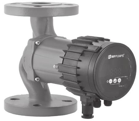


1 NMT SMART NMTC module SLO NAVODILA ZA VGRADNJO IN UPORABO GB D I INSTALLATION AND OPERATING MANUAL MONTAGE- UND BETRIEBSANLEITUNG Manuale di installazione ed uso v6
2 Compliance of the product with EU standards EU directive Harmonized standard Machinery 2006/42/EC EN 809 EN Low Voltage 2006/95/EC EN Electromagnetic compatibility EN ; EN (EMC) 2004/108/EC EN ; EN Ecodesign Directive (2009/125/EC) EN :2012 Circulators: Commission Regulation No. 641/2009. and EN :2012 Pump type EEI NMT(D) SMART (C) xx/120-xxx EEI 0,21 Part 2 NMT(D) SMART (C) xx/100-xxx EEI 0,21 Part 2 NMT(D) SMART (C) xx/80-xxx EEI 0,21 Part 2 NMT(D) SMART (C) xx/60-xxx EEI 0,21 Part 2 NMT(D) SMART (C) xx/40-xxx EEI 0,21 Part 2
3 Vsebina 1. Uporaba 4 2. Pretočni medij 4 3. Montaža 4 4. Električni priklop črpalke 5 5. Nastavitev in delovanje črpalke Pogled na nadzorno ploščo Vklop in izklop črpalke Funkcije tipk Nastavljanje režimov in parametrov črpalke Opis delovanja režimov črpalke Nastavitev črpalke na tovarniške nastavitve Dvojne črpalke NMTD SMART (C) 9 6. Tehnični podatki Pregled možnih napak in rešitev 11 SLO NMTC modul Vsebina 1. Splošno Uporaba Električni priklop Tehnični podatki 13-3-
4 SLO 1. Uporaba Črpalke NMT SMART so namenjene za prisilni obtok medija v sistemih za centralno ogrevanje. Črpalka neprekinjeno meri tlak in pretok ter prilagaja vrtljaje izbranemu tlaku. 2. Pretočni medij Za normalno delovanje črpalke je potrebno zagotoviti medij, ki je čista voda ali mešanica čiste vode in sredstva proti zmrzovanju, ki mora biti primerno za sistem centralnega ogrevanja. Voda mora ustrezati standardu o kvaliteti vode kot npr. VDI Medij mora biti brez agresivnih ali eksplozivnih dodatkov, brez primesi mineralnih olj in trdih ali vlaknenih delcev. Črpalke ne smemo uporabljati za črpanje gorljivih, eksplozivnih medijev in v eksplozivni atmosferi. Dovoljene temperature okolice in medija: Temperatura Temperatura medija okolice [ C] min. [ C] maks. [ C] 0 do Obratovanje izven priporočenih pogojev lahko skrajša življenjsko dobo in izniči garancijo. 3. Montaža Črpalka mora biti vgrajena tako, da je os elektromotorja v vodoravnem položaju (glej sliko 3.1). Dovoljene in prepovedane lege so prikazane v slikah 3.2. Puščica na hidravličnem delu označuje smer pretoka medija. V kolikor ni dovolj prostora za električno priključitev, je dovoljeno zasukati elektromotorni del tako, da je električni priključek v vodoravnem položaju. Položaj električnega priključka navpično nad elektromotornim delom črpalke ni dovoljen (glej sliko 3.3c). Pred zasukom moramo zapreti zaporna ventila na tlačni in sesalni strani črpalke in odviti vijake (slika 3.3). Zasuk elektromotornega dela izvedemo, kakor je prikazano v na slikah 3.3a ali 3.3b. -4-
5 Pred zagonom črpalke je potrebno črpalko napolniti z medijem in sistem popolnoma odzračiti. Za pravilno delovanje mora biti zagotovljen tlak na sesalni strani črpalke. Črpalka nima vijaka za odzračevanje, ker se samodejno odzrači, ko se odzrači sistem. Zrak v črpalki povzroča hrup. Ta po kratkem času izgine in črpalka deluje normalno. SLO POZOR! Maksimalni tlak v sistemu je 1 MPa (10 bar). Črpalka mora biti vedno zalita s črpanim medijem! Ohišje elektromotorja črpalke in odprtine (sl. 3.1 detajl A) med hidravličnim ohišjem in ohišjem elektromotorja ne smejo biti toplotno izolirani, ker bi izolacija preprečevala hlajenje in odvajanje kondenza iz pogonskega dela črpalke. Med obratovanjem se črpalka segreva ali jo segreva črpani medij, zato se je ne smemo dotikati - nevarnost opeklin. Dovoljeno delovno območje črpalke je definirano z diagramom v teh navodilih. 4. Električni priklop črpalke Priključitev črpalke mora opraviti strokovno usposobljena oseba. Priklop na električno omrežje je izveden s priloženim konektorjem, katerega montaža na priključni kabel je prikazana na sliki, ki je priložena konektorju. Električni priključek črpalke na omrežje (1~230V, 50Hz) mora biti izveden z ustreznim priključnim kablom (enakovredno priključnemu kablu 3G 1 mm², H05RR-F). Pri priklopu črpalke je treba upoštevati: priprava za ločitev vseh polov od napajalnega omrežja mora biti vgrajena v električni inštalaciji v skladu z nacionalnimi inštalacijskimi predpisi, priključitev priključne vrvi (kabla) ne sme potekati na način, da je v stiku z ohišjem aparata zaradi previsokih temperatur na ohišju, aparat ni namenjen uporabi osebam (upoštevajoč tudi otroke) z zmanjšanimi fizičnimi, čutnimi ali mentalnimi sposobnostmi ali s pomanjkanjem izkušenj oz. znanjem razen, če so pod nadzorom ali poučeni glede uporabe s strani osebe, odgovorne za njihovo varnost, otroci morajo biti pod nadzorom, da bi preprečili, da se ne igrajo z napravo. -5-
6 SLO 5. Nastavitev in delovanje črpalke 5.1. Pogled na nadzorno ploščo 1 Stolpični prikaz vrednosti 2 Številčni prikaz vrednosti 3 Prikaz enote trenutno izbranega parametra 4 Prikaz trenutno izbranega režima 5 tipka 6 tipka 7 tipka 5.2. Vklop in izklop črpalke Ko črpalko prvič priklopimo na omrežje, začne ta obratovati z tovarniškimi nastavitvami avtomatskega režima. Ob nadaljnjih vklopih bo črpalka začela obratovati z zadnjimi nastavitvami, ki so bile nastavljene ob njenem izklopu. Za izklop črpalke držimo pritisnjeno tipko 5 sekund, dokler se na zaslonu ne prikaže znak OFF. Ko je črpalka ugasnjena, je na njenem številčnem prikazu prikazan znak OFF. Za ponovni vklop črpalke pritisnemo za kratek čas tipko Funkcije tipk tipka Kratek pritisk: prehajanje med parametri navzdol, ko ne spreminjamo vrednosti parametrov, prehajanje med režimi navzdol, ko imamo vključeno izbiranje režimov, spreminjanje vrednosti navzdol, ko nastavljamo vrednosti parametrov. Dolg pritisk: 3 sekunde v kombinacijo s tipko vključimo nočni režim, 5 sekund ugasnemo črpalko, 5 sekund v kombinaciji s pritiskom in tipke nastavimo črpalko na tovarniške nastavitve. -6-
7 tipka Kratek pritisk: potrdimo trenutno nastavljeno vrednost tako režima kot parametra. Dolg pritisk: 3 sekunde sprožimo prehajanje med režimi, 5 sekund v kombinaciji z dolgim pritiskom in tipko nastavimo črpalko na tovarniške nastavitve. SLO tipka Kratek pritisk: Prehajanje med parametri navzgor, ko ne spreminjamo izbrane vrednosti parametrov, Prehajanje med režimi navzgor, ko imamo vključeno izbiranje režimov, Spreminjanje vrednosti navzgor, ko nastavljamo vrednosti parametrov. Dolg pritisk: 3 sekunde v kombinacijo s tipko vključimo nočni režim, 5 sekund v kombinaciji z pritiskom in tipke nastavimo črpalko na tovarniške nastavitve Nastavljanje režimov in parametrov črpalke Za nastavljanje režimov (razen nočnega režima) držimo tipko 3 sekunde, nato s ali tipko izberemo režim, v katerem hočemo, da črpalka deluje. Izbiro nato potrdimo z tipko. Po potrditvi režima se bo avtomatsko sprožila tudi izbira parametra (razen avtomatski režim), ki ga lahko nastavljamo pri izbranem režimu (glej posamezni režim). Parametru po potrebi nastavimo vrednost s in tipko, nato nastavitev potrdimo z tipko. V primeru, da ne želimo nastavljati parametra, samo pritisnemo tipko. Za vklop in izklop nočnega režima je potrebno hkrati držati tipki in pritisnjeni 3 sekunde. Znotraj režimov lahko pregledujemo vrednosti parametrov s in tipko. Parameter, ki ga lahko v režimu nastavljamo (glej posamezni režim), izberemo s tipko ter mu nastavimo vrednosti s in tipko. Nastavljeno vrednost potrdimo z tipko. -7-
8 SLO 5.5. Opis delovanja režimov črpalke Črpalka lahko deluje z 4 različnimi režimi delovanja, s katerimi lahko nastavimo črpalko na najbolj primeren način delovanja za posamezni sistem v katerem deluje. Režimi delovanja so: Avtomatski režim (tovarniška nastavitev) Proporcionalni tlak Konstantni tlak Konstantni vrtljaji Vsakega od teh režimov je mogoče kombinirati skupaj z nočnim režimom delovanja. A Avtomatski režim (tovarniška nastavitev) V avtomatskem režimu črpalka samodejno nastavlja tlak pri katerem deluje, glede na stanje hidravličnega sistema. S tem črpalka sama najde najbolj optimalno točko delovanja. Ta režim delovanja se priporoča za uporabo v večini sistemov. Parametrov ne moremo nastavljati, lahko jih le pregledujemo. Proporcionalni tlak Črpalka vzdržuje tlak, ki je odvisen od trenutnega pretoka. Tlak je enak nastavljenemu tlaku (Hset na risbi) pri maksimalni moči, pri pretoku 0 pa je enak 50% nastavljenega tlaka. Vmes se tlak spreminja linearno v odvisnosti od pretoka. V reguliranem načinu črpalki nastavljamo le tlak (Hset na risbi). Ostale parametre lahko le pregledujemo. H Hset 2 Maks. Hset + - Q Proporcionalni tlak Konstantni tlak Črpalka vzdržuje trenutno nastavljen tlak (Hset na risbi) od pretoka 0 do maksimalne moči, kjer se prične tlak zniževati. Pri konstantnem tlaku črpalki nastavljamo le tlak (Hset na risbi), katerega bo črpalka vzdrževala. Ostale parametre lahko le pregledujemo. H Hset Maks. + - Konstantni tlak Q -8-
9 Konstantni vrtljaji H Q SLO Črpalka deluje pri trenutno nastavljenih vrtljajih (RPMset na risbi). Pri konstantnih vrtljajih črpalki lahko nastavljamo le vrtljaje pri katerih bo obratovala. Ostale parametre lahko le pregledujemo. RPMset Maks. + Min. - Konstantni vrtljaji Q Nočni režim Ko črpalka deluje v nočnem režimu, avtomatsko preklaplja med trenutno izbrano delovno krivuljo v režimu in nočno krivuljo. Preklop je odvisen od temperature medija v sistemu. Ko je nočni režim pripravljen na delovanje, njegova ikona sveti in črpalka deluje v izbrani delovni krivulji režima. Ko črpalka zazna padec temperature medija za C (približno v času dveh ur), ikona prične utripati in črpalka preklopi na nočno krivuljo. Ko se temperatura medija ponovno dvigne, ikona preneha utripati in črpalka preide nazaj na delovno krivuljo v izbranem delovnem režimu. Nočni režim lahko deluje le v kombinaciji z zgoraj opisanimi režimi in ni samostojni režim delovanja Nastavitev črpalke na tovarniške nastavitve Za povrnitev tovarniških nastavitev črpalke je potrebno hkrati držati pritisnjene vse tri tipke 5 sekund. Črpalka se tako nastavi na avtomatski režim delovanja. Prejšnje nastavljene vrednosti višine in moči se bodo izbrisale Dvojne črpalke NMTD SMART (C) Črpalke imajo dvojno hidravlično ohišje z vgrajeno nepovratno loputo, ki se samodejno obrača glede na tok medija, ter dva ločena motorja. Črpalke imajo lahko možnost medsebojne komunikacije. Z možnostjo medsebojnega komuniciranja NMTD Smart C Brez možnosti medsebojnega komuniciranja NMTD Smart Pri tej uporabi, ne priporočamo uporabe nočnega režima delovanja črpalke. -9-
10 SLO NMTD Smart C V tem načinu lahko črpalki delujeta na več načinov, za medsebojne preklope črpalk skrbi NMTC modul: - Izmenično delovanje [tovarniško nastavljeni način] Ena črpalka deluje med tem, ko druga miruje. Črpalki samodejno izmenjata delovanje na vsake 24 ur, ali ko pride na eni črpalki do napake. - Rezervno delovanje - Ena črpalka stalno deluje, med tem, ko druga stalno miruje. Ob napaki na delujoči črpalki se bo samodejno vklopila mirujoča črpalka. Ta način se vklopi tako, da črpalko, ki hočemo, da miruje, ugasnemo tako, da pridržimo tipko za 5 sekund. - Vzporedno delovanje obe črpalki delujeta istočasno z istimi nastavitvami konstantnega tlaka. To delovanje se uporablja v primerih, kjer je zahteva po večjih pretokih, katerih enojna črpalka ne more doseči. Ko prva črpalka pride do svoje omejitve, se vklopi druga črpalka in zagotovi potrebno moč, da dosežemo večji pretok. Ta način se vključi, tako da na obeh črpalkah nastavimo enako nastavitev konstantnega tlaka. NMTD Smart V tem načinu lahko črpalke delujejo na več načinov, za vklop in izklop črpalk pa skrbi uporabnik. - Rezervno delovanje Ena črpalka stalo deluje, med tem, ko druga miruje. Mirujočo črpalko se vklopi v primeru okvare delujoče črpalke. Priporočljivo je, da se rezervno črpalko mesečno vklaplja. - Vzporedno delovanje Obe črpalki delujeta neodvisno ena od druge. Pri vzporednem delovanju morata biti črpalki nastavljeni na enako nastavitev konstantnih vrtljajev. 6. Tehnični podatki: NMT(D) SMART (C) Tip črpalke xx/120-xxx xx/100-xxx xx/80-xxx xx/60-xxx xx/40-xxx Moč P W W W 10-90W 10-60W Nazivni tok In 0,1-1,55A 0,1-1,5A 0,1-1,15A 0,1-0,75A 0,1-0,5A Priključna napetost 1~230V, 50Hz Zaščita motorja zunanja zaščita ni potrebna Razred zaščite IP44 Razred izolacije F Relativna zračna vlaga največ 95% Temperatura okolice 0-40 C Temperatura medija C Sistemski tlak do 1 MPa (10 bar) -10-
11 7. Pregled možnih napak in rešitev Če bo na črpalki prišlo do okvare, se bo na njenem zaslonu izpisala napaka, ki povzroča okvaro. Napake so označene kot: E X Y SLO Skupina napake Servisna koda Skupina napake: Skupina napake (X) Opis napake Možni vzrok in rešitev 1 suhi tek V črpalki ni medija. Preverite, če je v sistemu medij. 2 preobremenitev motorja 3 motor črpalke je dosegel previsoko temperaturo 4 napaka elektronike 5 okvara motorja/statorja Prevelika tokovna obremenitev ali blokiran rotor. Če se napaka ponavlja, preverite, če se rotor prosto vrti. Motor je dosegel previsoko temperaturo in se je preventivno ustavil. Ko se bo ohladil, se bo samodejno ponovno zagnal. Zaznana je bila napaka elektronike. Črpalka lahko še vedno deluje, a potrebuje servis. Mogoče je prišlo do prekinitve navitja motorja. Črpalka potrebuje servis. Servisna koda je namenjena vzdrževalcem in serviserjem. Če se črpalka ne odziva jo izklopite iz omrežja in ponovno priključite nazaj. -11-
12 SLO NMTC modul 1. Splošno Ta navodila vsebujejo osnovne podatke za priklop in varnost. Nadaljnja dokumentacija se nahaja na naši spletni strani na naslovu: Ali preko QR kode: 2. Uporaba NMTC modul je opcijski komunikacijski modul, ki se lahko doda na črpalko. Lahko je tovarniško ali naknadno vgrajen. NMTC modul ponuja: Ethernet povezava Modbus RTU povezava 0-10V zunanja regulacija 3 digitalni vhodi 1 relejski izhod -12-
13 3. Električni priklop Električni priklop in zaščita morata biti izvedena v skladu z lokalnimi predpisi. POZOR! Pred povezavo ali namestitvijo modula, izključite električno povezavo. Kabli morajo biti zvezani, tako da ne prečkajo pregradne stene na sredini modula. Kabli priključeni na rele (NO, C, NC) morajo biti ločeni od ostalih povezav z dodatno izolacijo. Zunanja plast kabla ne sme biti olupljena na več kot 15mm. SLO 4. Tehnični podatki Temperatura okolice: 0 C do 40 C. Vlaga okolice: <95 % relativne. Pridržujemo si pravico do tehničnih sprememb! -13-
14 Content GB 1. Use Medium types Installation Electrical connection Setup and operation Control panel Switching the pump on and off Pump functions Operation and setting of pump modes Mode descriptions Setting the pump to the factory settings Twin-head pumps NMTD SMART (C) Technical specifications Overview of possible errors and solutions 22 NMTC module Content 1. General Applications Electrical installation Technical data
15 1. Use The NMT SMART pumps are intended for forced circulation of the medium in central heating systems. The pump constantly measures pressure and flow, and adapts the speed to the selected pressure. GB 2. Medium types A medium that is pure water or a mixture of pure water and antifreeze, which is appropriate for a central heating system, must be provided. The water must meet water quality standards, such as: VDI The medium must be free from aggressive or explosive additives, free from mixtures of mineral oils and solid or fibrous particles. The pump should not be used for pumping flammable, explosive media, and in an explosive atmosphere. Permitted ambient and media temperature: Ambient Media temperature temperature [ C] min. [ C] max. [ C] 0 to Operation outside recommended conditions may shorten pump lifetime and void the warranty. 3. Installation The pump must be mounted so that the electric motor axis is in a horizontal position (see Figure 3.1). The permitted and prohibited positions are shown in Figure 3.2. The arrow on the hydraulic part indicates the direction of the medium flow. If there is not enough space for an electrical connection, the electric motor part can be rotated so that the electrical connector is in a horizontal position. A position with the electrical connector vertically above the motor is not permitted (see Figure 3.3c). Before we must close the block valve on the pressure and suction side of the pump and unscrew the screws (Figure 3.3). We can turn the electric motor part as shown in Figures 3.3a or 3.3b. -15-
16 GB Before starting the pump, the pump must be filled with the medium, and the air completely bled out of the system. For proper operation, pressure must be maintained on the suction side of the pump. The pump does not have screws for bleeding the air, as it is automatically bled with the system. The air in the pump generates noise. This disappears after a short time and the pump operates normally. WARNING! The maximum pressure in the system is 1 MPa (10 bar). The pump must always be filled with the pumped medium! The pump s openings and electric motor housing (Figure 3.1, detail A) between the hydraulic housing and the electric motor housing should not be insulated, since the thermal insulation might prevent cooling and condensate drain from the pump s motor housing. During operation, the pump heats up, or is heated by the pumped medium, and should not be touched risk of burns. The permitted working area of the pump is defined by the diagram in these instructions. 4. Electrical connection Connection of the pump must be carried out by qualified personnel. Connection to the power supply is carried out with the enclosed connector, the mounting of which is shown in the picture accompanying the connector. The electric connection of the pump to the network (1~230V, 50Hz) must be done with the appropriate power cord (equivalent to a 3G 1 mm ², H05RR-F connection cable). When connecting the pump, the following must be considered: the device for separating all the phases from the power supply must be installed in the electric installation in accordance with the national installation regulations, connection of the connecting cable must be done in a manner that ensures it is never in contact with the casing of the device, due to the high temperatures of the casing, the device should not be used by persons (including children) with reduced physical, sensory or mental abilities, or with lack of experience or knowledge, unless they are supervised or instructed on the use by a person responsible for their safety, children should always be supervised to prevent playing with the device. -16-
17 5. Setup and operation 5.1. Control panel 1 Bar display of values 2 Numerical display of values 3 Unit display of the currently selected parameter 4 Display of the currently selected mode 5 key 6 key 7 key GB 5.2. Switching the pump on and off When the pump is connected to the network for the first time, it operates with the factory settings in automatic mode. With subsequent start-ups, the pump will operate with the last settings that were set prior to its shut-down. To switch the pump off, press and hold the key for 5 seconds, until OFF is shown on the display. When the pump is switched off, the numerical display shows OFF. To turn the pump on, press the key briefly Pump functions Key Short press: Scrolling through parameters downwards when not changing parameter values, Scrolling through modes downwards when mode selection is selected, Changing parameters downwards when setting parameter values. Long press: 3 seconds together with key to select night mode, 5 seconds to switch off the pump, 5 seconds together with and keys to restore pump to factory settings. -17-
18 GB Key Short press: To confirm currently selected values of both mode and parameter. Long press: 3 seconds to trigger mode selection, 5 seconds together with long press on and keys to restore pump to factory settings. Key Short press: Scrolling through parameters upwards when not changing parameter values, Scrolling through modes upwards when mode selection is selected, Changing parameters downwards when setting parameter values. Long press: 3 seconds together with key to select night mode, 5 seconds together with and keys to restore pump to factory settings Operation and setting of pump modes For transition between modes (except for night mode), we hold the key for 3 seconds and then select the mode in which we wish the pump to operate with or keys. We confirm the selection with the key. After confirming the mode, the parameter, that can be set in this mode will automatically be chosen and displayed (except for auto mode). If necessary, we set the parameter value with and keys, and then confirm the setting with the key or just press the key. To turn on and turn off the night mode, we simultaneously press and keys and hold them for 3 seconds. We can scroll through the parameter values within a mode with and keys. We select the parameter that can be adjusted (see individual mode) in the mode with the key and set the desired value with and keys. We confirm the selected value with the key. -18-
19 5.5. Mode descriptions The pump can operate in 4 different modes. We can set the pump in the most appropriate mode, depending on the system where the pump operates. The pump modes: Automatic mode (factory settings) Proportional pressure Constant pressure Constant speed GB Each mode can be combined together with night mode. A Automatic mode (factory setting) In automatic mode the pump automatically sets the operating pressure, depending on the hydraulic system. By doing so, the pump finds the optimal operating position. This mode is recommended in most systems. The parameters cannot be set; they can only be scrolled through. Proportional pressure The pump maintains the pressure with relation to the current flow. The pressure is equal to the set pressure (Hset on the drawing) at maximum power; at 0 flow it is equal to 50% of the set pressure. In between, the pressure changes linearly, relative to the flow. In regulated mode we can only set the pump pressure (Hset on the drawing). We can only scroll through the other parameters. H Hset 2 Max. Hset + - Q Proportional pressure Constant pressure The pump maintains the currently set pressure (Hset on the drawing), from 0 flow to maximum power, where the pressure begins to drop. At constant pressure, we can only set the pressure (Hset on the drawing) which the pump will maintain. We can only scroll through the other parameters H Hset Max. + - Q Constant pressure
20 Constant speed H GB The pump operates with the currently set speed (RPMset on the drawing). In the unregulated mode, we can only set the speed at which the pump will operate. We can only scroll through the other parameters. RPMset Min. - + Max. Q Constant revolutions Night mode When the pump operates in night mode, it automatically switches between the selected operating curve in the mode and night curve. The transition to the night mode depends on the media temperature in the system. When the night mode is prepared for operating, its icon illuminates and the pump operates in the selected operating curve of the mode. When the pump identifies the media temperature fall by 15-20C (approximately during 2 hours), the icon starts to blink and the pump switches to the night curve. When the media temperature rises again, the icon stops blinking and the pump passes over to the operating curve in the selected operating mode. The night mode operates only in combination with the above indicated modes. It is not an independent operating mode Setting the pump to the factory settings To restore factory settings to the pump, it is necessary to press and hold all three keys for 5 seconds. The pump is set to the automatic mode of operation. The previously set values for pressure and revolutions will be deleted Twin-head pumps NMTD SMART (C) Pumps have a common hydraulic housing that is equipped with a changeover flap and two pump heads, separately connected to the electrical grid. Pumps that communicate with each other. NMTD Smart C Pumps without an communication option NMTD Smart With this use, we recommend that night mode isn't used. -20-
21 NMTD Smart C In this mode both pumps can work in different modes, switching between pumps is made by NMTC module. - Alternating mode [factory set] - One pump works, while the other one is in standby. Pumps automatically switch on and in to standby every 24 hours, or when an error occurs on one pump. - Reserve mode - One pump is always on, while the other one is in standby. If an error occurs, then the reserve pump will turn on. This mode is turned on, so that you put the pump that you want to be in standby, to standby by holding key for 5 seconds. - Combined mode both pumps work with the same head in constant pressure mode. This mode is used when there is a need for a flow that a single pump can't reach. When the limit of the first pump is reached, then the other one will turn on supply the needed power to reach that flow. This mode is activated, so that you set the same constant pressure head on both pumps. GB NMTD Smart In this mode the pumps can work in different modes. The user takes care of switching on and off of the pumps. - Reserve mode - One pump works, while the other one is in standby. It is recommended that the reserve pump is turned on at least once a month. - Combined mode Both pumps work, regardless of each other. Pumps need to be set at the same constant speed. 6. Technical specifications NMT(D) SMART (C) Pump type xx/120-xxx xx/100-xxx xx/80-xxx xx/60-xxx xx/40-xxx Power P W W W 10-90W 10-60W Rated current In 0,1-1,55A 0,1-1,5A 0,1-1,15A 0,1-0,75A 0,1-0,5A Power supply 1~230V, 50Hz Motor protection External protection is not necessary Protection class IP44 Insulation class F Relative humidity max 95% Ambient temperature 0-40 C Medium temperature C System pressure up to 1 MPa (10 bar) -21-
22 7. Overview of possible errors and solutions GB If pump failure occurs, the error causing the failure will appear in the display screen. Errors are identified as: E X Y Error group Service code Error group: Error group (X) Error description Possible cause and solution 1 Low load detected There is no medium in the pump. Check if there is medium in the system. 2 Motor overload Excessive current load or blocked rotor. If the issue persists, check if the rotor is spinning freely. 3 Motor too hot Motor has exceeded allowed temperature and is now stopped to cool down. Once cooled, it will automatically restart. 4 Electronics error An electronics error was detected. The pump can still operate, but needs servicing. 5 Motor/stator failure There could be an interruption in the motor winding. Pump needs servicing. The service code is intended for service personal. If the pump is unresponsive, disconnect and connect it back to the electrical grid. -22-
23 NMTC module 1. General This manual contains only basic information regarding module installation and safety. Further product documentation can be found on our website on this address: GB Or by QR code: 2. Applications and further product documentation NMTC module is an optional communication module that can be added to the pump. It can be factory built-in, or retrofitted later. NMTC module offers: Ethernet connection Modbus RTU connection 0-10V external regulation 3 digital inputs 1 relay output -23-
24 3. Electrical installation Electrical connection and protection must be carried out according to local regulations. GB WARNING! Before making any connection or fitting to the module, switch off power supply. Wires should be routed so no wire crosses the center barrier. Relay cable (NO, C, NC) must be separated from all other wiring with reinforced insulation. Cable outer layer must not be stripped longer than 15 mm. 4. Technical data Ambient temperature: 0 C to 40 C. Ambient humidity: <95 % relative, non-condensing. We reserve the right to make technical changes! -24-
25 INHALTSVERZEICHNIS 1. Allgemeine Beschreibung Fördermedien Installation Stromanschluss der Pumpe Einrichtung und Inbetriebnahme Funktionselemente am Bedienfeld Inbetriebnahme Funktionstasten Einstellen der Betriebsarten Beschreibung der Betriebsarten Rücksetzen der Pumpe auf Werkseinstellung Doppelpumpe NMTD SMART (C) Technische Daten Fehlermeldung und Abhilfe 33 D NMTC modul INHALTSVERZEICHNIS 1. Allgemein Inbetriebnahme Elektrischer Anschluss Technische Daten
26 1. Allgemeine Beschreibung Die Umwälzpumpe NMT SMART ist für die Umwälzung von Wasser in Heizungsanlagen und Trinkwarmwasseranlagen bestimmt. Sie unterscheiden sich von den bestehenden Standardumwälzpumpen darin, dass sie sich durch Regelung Proportionaldruckregelung oder Konstantdruckregelung der Anlage kontinuierlich anpassen und dadurch eine optimale Einstellung des Betriebspunktes erreichen. D 2. Fördermedien Reine, dünnflüssige Medien, die für Zentralheizungsanlage geeignet sind. Das Wasser soll den gängigen Normen entsprechen, wie z.b.: VDI Das Medium darf keine aggressiven oder explosiven Additive enthalten, keine Beimengen von mineralischen Ölen oder faserigen Partikel. Die Pumpe darf nicht zur Förderung von entflammbaren und explosiven Medien benutzt werden. Zugelassene Medientemperatur Raumtemp. [ C] min. [ C] max. [ C] 0 bis Der Betrieb der Pumpe außerhalb der angebenen Raum- und Mediumtemperaturen kann die Lebensdauer der Pumpe beeinträchtigen und die Gewährleistung aufheben. 3. Installation Die Umwälzpumpe muss so installiert werden, dass sich die Achse des Elektromotors in horizontaler Position befindet (siehe Bild 3.1). Zugelassene und unzulässige Positionen sind auf Bild 3.2 aufgezeigt. Der Pfeil auf der Hydraulik zeigt die Richtung des Durchflussmediums an. Falls nicht genug Platz für den Stromanschluss vorhanden ist, kann der Elektromotor in die horizontale Position gedreht werden. Die vertikale Position ist nicht erlaubt (siehe Bild 3.3c). Vor der Versetzung muss das Vorund Rücklaufventil geschlossen werden, sowie die Schrauben gelöst (Bild 3.3). Der Elektromotor wird gedreht, wie auf Bild 3.3a und 3.3b aufgezeigt. -26-
27 Vor Inbetriebnahme der Pumpe ist die Heizungsanlage mit Heizungswasser zu befüllen und zu entlüften. Für den einwandfreien Betrieb muss am Saugstutzen der Mindest-Zulaufdruck gegeben sein. Die Umwälzpumpe ist selbstentlüftend und muss daher vor Inbetriebnahme nicht entlüftet werden. Luft in der Pumpe kann Geräusche verursachen, jedoch entweicht nach kurzer Zeit diese selbständig und eventuelle Geräusche verschwinden. ACHTUNG! Der maximale Druck im System beträgt 1 MPa (10 bar). Die Pumpe muss mit Fördermedium gefüllt sein und darf niemals trocken laufen. Die Öffnungen zum Ablauf des Kondenswassers (siehe Bild 3.1 Detail A), den Elektromotor sowie den Klemmkasten niemals abdämmen. Während des Betriebes der Pumpe erwärmt sich diese und darf daher nicht berührt werden. Der zugelassene Arbeitsbereich der Pumpe wird im Diagramm in dieser Anleitung dargestellt. D 4. Stromanschluss der Pumpe Der elektrische Anschluss der Pumpe darf nur von qualifiziertem Fachpersonal durchgeführt werden. Der Anschluss an das Stromnetz erfolgt mit Hilfe des mitgelieferten Steckers, Anschluss an das Kabel siehe Beipackzettel. Der Elektroanschluss der Pumpe an das Stromnetz (1~230V, 50Hz) muss mit einem entsprechenden Netzkabel ausgeführt werden (3G 1 mm ², H05RR-F Anschlusskabel). Der elektrische Anschluss und die erforderlichen Schutzmaßnahmen sind in Übereinstimmung mit den örtlichen Vorschriften vorzunehmen. -27-
28 5. Einrichtung und Inbetriebnahme 5.1. Funktionselemente am Bedienfeld D 1 Leuchtfelder zur Wertanzeige 2 Numerische Wertanzeige 3 Anzeige der ausgewählten Parameter 4 Anzeige der Betriebsart 5 Taste 6 Taste 7 Taste 5.2. Inbetriebnahme Bei erster Inbetriebnahme arbeitet die Pumpe nach Werkseinstellung im Automatikbetrieb. Zum Ausschalten der Pumpe drücken Sie 5 Sekunden die Taste. Im ausgeschalteten Zustand zeigt die Anzeige OFF an. Zum Einschalten drücken Sie die Taste. Die Pumpe merkt sich die letzte Sollwerteinstellung und läuft bei Wiederinbetriebnahme in dieser an Funktionstasten Taste Kurz halten: Umstellen der Parameter abwärts, Parameterwerte werden nicht verändert Umstellen der Betriebsart abwärts, bei Auswahl der Betriebsart Umstellen der Parameterwerte abwärts, bei Auswahl der Parameterwerte Lang halten: 3 Sekunden gemeinsam mit der Taste für Nachtabsenkung 5 Sekunden um die Pumpe abzuschalten 5 Sekunden gemeinsam mit der und Taste für Werkseinstellung -28-
29 Taste Kurz halten: Um die ausgewählten Werte der Betriebsart und der Parameter zu bestätigen Lang halten: 3 Sekunden um den Wechsel zwischen den Betriebsarten einzuleiten 5 Sekunden gemeinsam mit der und Taste für die Werkseinstellungen der Pumpe Taste Kurz halten: Umstellen der Parameter aufwärts, wenn Parameterwerte nicht verändert werden Umstellen der Betriebsart aufwärts, für die Auswahl der Betriebsart Umstellen der Parameterwerte aufwärts, für die Auswahl der Parameterwerte Lang halten: 3 Sekunden gemeinsam mit der Taste für Nachtabsenkung 5 Sekunden gemeinsam mit der und Taste für die Werkseinstellung D 5.4. Einstellen der Betriebsarten Für den Wechsel zwischen den Betriebsarten drücken Sie die Taste 3 Sekunden und wählen danach die gewünschte Betriebsart mit der oder Taste aus. Die Auswahl wird mit der Taste bestätigt. Nach Bestätigung der Betriebsart wird automatisch die Auswahl der Parameter angezeigt (auβer im Automodus). Man kann diese in Bezug auf die ausgewählte Betriebsart einstellen (siehe individuelle Betriebsart). Mit der und Taste stellen Sie die Parameterwerte ein und bestätigen mit der Taste. Zum Ein- und Ausschalten der Nachtabsenkung halten Sie die Taste und Taste gemeinsam 3 Sekunden gedrückt. Innerhalb der Betriebsarten können die Parameterwerte mit der und Taste überprüft werden. Durch Drücken der Taste und mit Hilfe der und Taste werden diese verändert und mit der Taste bestätigt. -29-
30 5.5. Beschreibung der Betriebsarten D Die Umwälzpumpe arbeitet in 4 verschiedenen Betriebsarten in denen die Pumpenleistung optimal an die aktuelle Anlagenbedingung angepasst werden kann. Betriebsarten: Automatik (Werkseinstellung) Proportionaler Druck Konstanter Druck Konstante Umdrehungen Jede dieser Betriebsarten kann mit der Betriebsart Nachtabsenkung kombiniert werden. A Automatik (Werkseinstellung) Im Automatik Modus passt sich die Pumpenleistung automatisch dem Druck der Heizanlage an und bestimmt den optimal Betriebspunkt. Diese Betriebsart wird in den meisten Fällen empfohlen. In dieser Betriebsart können die Parameter nur überprüft werden, nicht verändert. Proportionaler Druck H In dieser Betriebsart wird der Differenzdruck in Max. Abhängigkeit vom Förderstrom geregelt. Der Druck entspricht dem eingestelltem Druck (Hset) bei maximaler + Kraft, bei 0 Durchfluss entspricht dieser 50% des Hset - 2 eingestellten Druckes. Dazwischen verändert sich der Druck linear in Abhängigkeit zum Durchfluss. Bei regulierbarer Betriebsart wird nur der Druck (Hset) eingestellt, alle anderen Parameter können nur kontrolliert werden. Hset Q Proportionaler Druck Konstanter Druck Die Pumpe behält den eingestellten Druck bei (Hset) von 0 bis zur maximalen Stärke, danach beginnt der Druck zu fallen. Bei konstantem Druck kann nur der Druck, den die Pumpe halten soll, eingestellt werden. Die anderen Parameter können nur kontrolliert werden. Proportionaler Druck H Max. + Hset - Konstanter Druck Q -30-
31 Konstante Umdrehungen H Die Pumpe arbeitet unter den eingestellten Umdrehungen (RPMset). In dieser Betriebsart können nur die Umdrehungen eingestellt werden, die anderen Parameter können nur kontrolliert werden. RPMset Min. - + Max. Q Konstante Umdrehungen Nachtabsenkung D Im Betriebszustand Nachtabsenkung (Anzeige am Bedienfeld leuchtet) wechselt die Pumpe automatisch, abhängig von der Medientemperatur, zwischen der eingestellten Betriebsart und der Nachtabsenkung. Bei einem Temperaturabfall des Mediums von C (innerhalb ca. 2 Stunden), beginnt die Anzeige Nachtabsenkung zu blinken und die Pumpe wechselt auf Nachtbetrieb. Bei Temperaturanstieg des Mediums leuchtet die Anzeige und die Pumpe wechselt in die zuvor gewählte Betriebsart zurück. Die Nachtabsenkung arbeitet nur in Verbindung mit einer der oben aufgeführten Betriebsarten Rücksetzen der Pumpe auf Werkseinstellung Zum Rücksetzen der Pumpe auf die Werkseinstellung halten Sie alle Tasten gleichzeitig 5 Sekunden gedrückt. Die Pumpe wechselt in den Automodus, alle vorherigen Sollwerteinstellungen sind gelöscht NMTD Smart (C) Doppelpumpen bestehen aus zwei Pumpenköpfen, die in einem Gehäuse hydraulisch parallel angeordnet sind. Eine eingebaute förderstromgesteuerte Umschaltklappe verhindert den Rückströmen durch die stehende Pumpe. Jeder Pumpenkopf wird separat an den Stromkreis angeschlossen. Die NMTD Smart C Serie ermöglich mit Hilfe des Kommunikationsmodules (C) die Kommunikation der einzelnen Pumpenköpfe miteinander, dies ist bei der NMTD Smart Serie ohne Kommunikationsmodul nicht möglich. Die Funktion Nachtabsenkung ist bei Doppelpumpen nicht empfehlenswert! -31-
32 D Zudem bietet die NMTD Smart C Pumpe folgende Betriebsarten: Wechselbetrieb (Werkseinstellung) die Pumpenköpfe arbeiten im Wechselbetrieb. Während ein Pumpenkopf fördert, steht der andere still. Alle 24 Stunden, oder im Falle einer Störung, findet ein Wechsel statt Reservebetrieb - Ein Pumpenkopf übernimmt permanent die Funktion, der andere Pumpenkopf steht auf Reservebetrieb. Bei einer Fehlermeldung übernimmt die Reservepumpe die Funktion. Durch Drücken der Taste für 5 Sekunden auf der ruhenden Pumpe wird diese ausgeschaltet und der Reservebetrieb aktiviert Parallelbetrieb - Beide Pumpen arbeiten gleichzeitig. Förderhöhe bzw. Drehzahl der einzelnen Pumpenköpfe wird bei beiden auf identische Parameter eingestellt und aktiviert somit diese Arbeitsweise. Wenn ein einzelner Pumpenkopf die erforderliche Pumpenleistung nicht erreichen kann, wird der zweite Pumpenkopf zur Unterstützung aktiviert. NMTD Smart Folgende Betriebsarten sind möglich, für das Ein- und Ausschalten sorgt der Betreiber: Wechselbetrieb die Pumpenköpfe arbeiten im Wechselbetrieb. Während ein Pumpenkopf fördert, steht der andere still. Im Falle einer Störung muss die Reservepumpe in Betrieb genommen werden. Wir empfehlen eine monatliche Inbetriebnahme der Reservepumpe. Parallelbetrieb - Beide Pumpen arbeiten gleichzeitig, unabhängig voneinander. Förderhöhe bzw. Drehzahl der einzelnen Pumpenköpfe wird bei beiden auf identische Parameter eingestellt. 6. Technische Daten NMT(D) SMART (C) Pumpentyp xx/120-xxx xx/100-xxx xx/80-xxx xx/60-xxx xx/40-xxx Stärke P W W W 10-90W 10-60W Bemessungsstrom In 0,1-1,55A 0,1-1,5A 0,1-1,15A 0,1-0,75A 0,1-0,5A Stromversorgung 1~230V, 50Hz Motorschutz externer Schutz ist nicht notwendig Schutzklasse IP44 Isolierungsklasse F Relative Feuchtigkeit max. 95% Raumtemperatur 0-40 C Medientemperatur C Systemdruck bis zu 1 MPa (10 bar) -32-
33 7. Fehlermeldung und Abhilfe Bei Fehlermeldung zeigt die Pumpe folgende Meldung an: E X Y D Fehlergruppe Service code Fehlergruppe Fehler-gruppe (X) Fehlerbeschreibung Mögliche Ursache und Abhilfe 1 Trockenlauf 2 Motorüberlastung Fördermedium fehlt, überprüfen sie den Inhalt der Heizanlage Überhöhte Stromspannung oder blockierter Rotor. Überprüfen Sie den Rotor bei wiederholter Fehlermeldung 3 Motorüberhitzung 4 Elektronikfehler 5 Defekt am Motor/Stator Zu hohe Motortemperatur erreicht, automatisch präventiv abgeschaltet. Nach Abkühlung startet die Pumpe automatisch. Elektronikfehler, Pumpe läuft zwar aber Servicetechniker kontaktieren. Motorstörung, Servicetechniker kontaktieren. Der Servicecode dient dem Servicetechniker und dem Werksdienst Falls die Pumpe nicht reagiert, vom Stromnetz trennen und erneut anschliessen. -33-
34 NMTC modul 1. Allgemein Die Betriebsanleitung beinhaltet nur allgemeine Hinweise zur Inbetriebnahme und Sicherheit. Weiter Informationen und Details findensie auf unserer Internetseite unter: D Oder QR Kode: 2. Inbetriebnahme Das NMTC Modul ist ein optionales Kommunikationsmodul, das nachträglich auf die Pumpe installiert werden kann oder bereits in der Pumpe integriert ausgeliefert wird. NMTC Modul Funktionen: Ethernet Verbindung Modbus RTU Verbindung 0-10V Steuerungsausgang 3 digitale Eingänge 1 Relaisausgang -34-
35 3. Elektrischer Anschluss Der elektrische Anschluss der Pumpe an das Stromnetz muss nach den Weisungen und Vorschriften lokaler Energieunternehmen durchgeführt werden. BEACHTEN! Vor Inbetriebnahme bzw. Montage des Modules Stromzufuhr unterbrechen Kabelanschluss des Modules seitlich legen, Überkreuzungen über der Modemplatine vermeiden. Die Relaisanschlüsse (NO, C, NC) müssen getrennt von den übrigen Anschlüssen isoliert werden, nicht mehr als 15 mm abisoliert. D 4. Technische Daten Temperatur Umfeld: 0 C bis 40 C. Luftfeuchtigkeit Umfeld: <95 % relative Luftfeuchtigkeit Wir behalten uns das Recht vor, technische Änderungen vorzunehmen! -35-
36 Contenuti I 1. Utilizzo Fluidi Montaggio Collegamento elettrico Impostazione e funzionamento Interfaccia di impostazione Accensione e spegnimento Funzionalita dei pulsanti Impostazione dei regimi e dei parametri Descrizione del funzionamento dei regimi Ritorno alle impostazioni di fabbrica Circolatori gemellari NMTD SMART (C) Dati tecnici Problemi e soluzioni 44 Modulo NMTC Contenuti 1. Generale Utilizzo Collegamento elettrico Dati tecnici
37 1. Utilizzo I circolatori NMT SMART sono dedicati alla circolazione forzata del fluido all interno di sistemi per il riscaldamento centralizzato. Il circolatore fluido in modo continuo la pressione e la portata e adatta la velocita di rotazione alla pressione selezionata. 2. Fluidi Per un corretto funzionamento del circolatore si deve utilizzare un fluido, che sia acqua pulita oppure un miscuglio di acqua pulita e liquido anticongelante adatto a sistemi di riscaldamento centralizzato. L acqua dev essere conforme agli standard di qualita come per esempio il VDI2035. Il fluido non deve contenere additivi aggressivi o esplosivi, olii minerali, parti solide o fibrose. I circolatori non devono essere utilizzati per pompaggio di fluidi infiammabili, esplosivi ed in ambienti esplosivi. Temperature ambiente e fluido consentite: I Temperatura Temperatura fluido ambiente [ C] min. [ C] max. [ C] 0 a Il funzionamento al di fuori delle condizioni raccomandate puo accorciarne la vita e invalidare la garanzia. 3. Montaggio Il circolatore dev essere montato di modo che l asse dell elettromotore si trovi in posizione orizzonatale (Figura 3.1). Le posizioni consentite e vietate sono rappresentate in foto 3.2. La freccia sulla parte idraulica del corpo pompa indica la direzione del flusso del fluido. Nel caso in cui non ci fosse abbastanza spazio per la connessione, e consentito girare l elettromotore di modo che il connettore elettrico si trovi in posizione orizzontale. E assolutamente vietata la posizione in cui il connettore si trovi verticalmente -37-
38 sopra l elettromotore (Figura 3.3c). Prima di effettuare la rotazione si deve chiudere le valvole sulla parte aspirante e comprimente e poi svitare le viti (Figura 3.3). La rotazione della parte elettromotore si effettua come mostrato in Figura 3.3a oppure 3.3b. Prima dell avviamento del circolatore, questi dev essere riempito di fluido e il sistema dev essere sfiatato. Per il corretto funzionamento si deve assicurare pressione sulla parte aspirante del circolatore. Il circolatore non ha una vite di sfiato, perche si sfiata in automatico quando si effettua lo sfiato del sistema. L aria all interno del circolatore e causa di rumore. Questo sparisce dopo poco tempo e il circolatore funziona normalmente. I ATTENZIONE! La pressione massima del sistema e 1Mpa (10 bar) Il circolatore deve sempre contenere il fluido! Il corpo dell elettromotore e le fessure (Figura 3.1, dettaglio A) tra il corpo pompa e il corpo dell elettromotore non devono essere termicamente isolati, perche l isolamento impedirebbe il raffreddamento e l espulsione della condensa dalla parte motore. Durante il funzionamento il circolatore si scalda o viene riscaldato dal fluido pompato, per questo e vietato toccarlo pericolo di ustioni. La zona di lavoro del circolatore e definita con un diagramma incluso nel presente manuale istruzioni. 4. Collegamento elettrico Il collegamento elettrico del circolatore deve essere fatto da persona abilitata. Il collegamento alla rete elettrica si effettua mediante il connettore incluso, il cui montaggio al cavo e rappresentato nella figura che e inclusa col connettore. Il collegamento del circolatore alla rete elettrica (1~230V,50Hz) dev essere realizzato con cavo opportuno (equivalente al cavo 3G 1mm², H05RR-F). Nella connessione si deve prestare attenzione a quanto segue: Il sistema di isolamento dei poli dalla rete elettrica dev essere integrato nell installazione elettrica secondo le normative vigenti. Il cavo di collegamento non deve scorrere sul corpo pompa a causa delle alte temperature che quest ultimo raggiunge. L utilizzo non e consentito a persone (inclusi i bambini) con limitate capacita psico-fisiche e con limitata esperienza e conoscenza, tranne nel caso in cui sono sotto sorveglianza o istruiti all utilizzo da parte di persone responsabili della loro sicurezza. I bambini devono essere sorvegliati, in modo da evitare che giochino con l apparecchio -38-
39 5. Impostazione e funzionamento 5.1. Interfaccia di impostazione 1 Indicatore progressivo 2 Indicatore di valore 3 Indicatore dell unita di misura del parametro selezionato 4 Indicazione del regime impostato 5 pulsante 6 pulsante 7 pulsante I 5.2. Accensione e spegnimento Al primo avviamento del circolatore, questi funzionera secondo il regime automatico (preimpostazione di fabbrica). Nei successivi avviamenti il circolatore funzionera secondo le ultime impostazioni impostate prima dello spegnimento. Per lo spegnimento tenere premuto il tasto per 5 secondi, finche sul display non compare la scritta OFF. Quando il circolatore e spento, sul display compare la scritta OFF. Per l avviamento del circolatore premere semplicemente sul pulsante Funzionalita dei pulsanti pulsante Pressione breve passaggio tra i parametri verso il basso, quando non variamo i valori dei parametri passaggiro tra i regimi verso il basso, quando e attiva la selezione dei regimi cambiamento dei valori verso il basso, quando impostiamo i valori dei parametri -39-
40 Pressione lunga: 3 secondi contemporaneamente col pulsante, attiviamo il regime notturno 5 secondi, spegnamo il circolatore 5 secondi contemporaneamente col pulsante e, rimettiamo il circolatore alle impostazioni iniziali di fabbrica I pulsante Pressione breve confermiamo l impostazione attuale di regime e parametro Pressione lunga: 3 secondi, attiviamo il passaggio tra i regimi 5 secondi contemporaneamente col pulsante e, rimettiamo il circolatore alle impostazioni iniziali di fabbrica pulsante Pressione breve passaggio tra i parametri verso l alto, quando non variamo i valori dei parametri passaggiro tra i regimi verso l alto, quando e attiva la selezione dei regimi cambiamento dei valori verso l alto, quando impostiamo i valori dei parametri Pressione lunga: 3 secondi contemporaneamente col pulsante, attiviamo il regime notturno 5 secondi contemporaneamente col pulsante e, rimettiamo il circolatore alle impostazioni iniziali di fabbrica 5.4. Impostazione dei regimi e dei parametri Per impostare il regime (tranne quello notturno) teniamo premuto il pulsante per 3 secondi, dopodiche con i tasti e selezioniamo il regime con il quale vogliamo che il circolatore funzioni. Confermiamo la selezione mediante la pressione del tasto. Alla conferma del regime (tranne che per il regime automatico), automaticamente si attiva la selezione del parametro relativo a tale regime selezionato (fare riferimento al regime). Impostiamo il valore del parametro coi pulsanti e, confermando la selezione col tasto. Nel caso non vogliamo impostare il valore del parametro, premiamo semplicemente sul tasto. -40-
41 Per l attivazione e la disattivazione del regime notturno, si deve tenere contemporaneamente premuti i pulsanti e per 3 secondi. All interno del regime, possiamo verificare i parametri impostati con i tasti e. Il parametro all interno del regime (fare riferimento al regime), lo selezioniamo col pulsante dopodiche ne impostiamo il valore mediante i tasti e. Confermiamo il valore impostato con la pressione del tasto Descrizione del funzionamento dei regimi Il circolatore puo funzionare secondo 4 diversi regimi, secondo cui possiamo impostare il circolatore di modo che funzioni nel modo piu adatto possibile al sistema in cui si trova. I regimi di funzionamento sono: Regime automatico (preimpostazione di fabbrica) A pressione proporzionale A pressione costante A velocita costante Ognuno di questi regimi puo essere usato in combinazione col regime notturno. I A Regime automatico (preimpostazione di fabbrica) In regime automatico il circolatore regola automaticamente la pressione di lavoro in base alla situazione del sistema idraulico. In tale modo, il circolatore trova autonomamente il punto di lavoro ottimale L utilizzo di questo regime e raccomandato nella maggior parte dei sistemi. Non possiamo impostare parametri, ma possiamo solamente visualizzarli. A pressione proporzionale Il circolatore mantiene la pressione in funzione della portata istantanea. La pressione e uguale a quella impostata (Hset in Figura) alla massima potenza, alla portata 0 e invece uguale al 50% della pressione impostata. La pressione nei punti intermedi varia linearmente in funzione della portata. H Max. Hset + Hset - 2 Q Proportionaler A pressione proporzionale Druck In questo regime possiamo impostare solamente il parametro pressione (Hset in Figura). Gli altri parametri possono essere solo consultati. -41-
42 A pressione costante Il circolatore mantiene la pressione impostata (Hset in Figura) dalla portata 0 alla portata a potenza massima, punto in cui la pressione inizia a diminuire. In questo regime possiamo impostare solamente il parametro pressione (Hset in Figura) che il circolatore manterra costante. Gli altri parametri possono essere solo consultati. Proportionaler Druck H Max. + Hset - A pressione Konstanter constante Druck Q A velocita costante I Il circolatore funziona alla velocita impostata (RPMset in Figura). In questo regime possiamo impostare solamente il parametro di velocita che il circolatore dovra mantenere. Gli altri parametri possono essere solo consultati. Regime notturno H RPMset Min. - Max. Q A Konstante velocita' Umdrehungen costante + Quando questo regime e impostato, il circolatore cambia automaticamente tra la curva di lavoro impostata e la curva di regime notturno. Il cambio viene fatto in funzione della temperatura del fluido nel sistema. Quando il regime notturno e impostato, il LED del simbolo relativo e acceso e il circolatore lavora secondo la curva impostata. Nel momento in cui il circolatore rileva una caduta di temperatura di C (nell arco di cca 2 ore), il simbolo inizia a lampeggiare e il circolatore passa alla curva di regime notturno. All aumentare della temperatura del fluido, il simbolo smette di lampeggiare e il circolatore ritorna sulla curva del regime impostato precedentemente. Il regime notturno funziona solo come opzione dei regimi sopra citati, non puo funzionare (essere selezionato) da solo Ritorno alle impostazioni di fabbrica Per rimettere il circolatore alle impostazioni di fabbrica, si deve tenere premuti i tre pulsanti contemporaneamente per 5 secondi. Il circolatori si imposta cosi al regime automatico. I parametri impostati precedentemente di prevalenza e potenza si cancellano. -42-
43 5.7. Circolatori gemellari NMTD SMART (C) I circolatori hanno corpo pompa doppio con integrata una valvola antiriflusso (che si posiziona in base al flusso del fluido) e due motori separati. I circolatori hanno la possibilita di comunicare tra di loro. In questa configurazione (NMTD Smart C) sconsigliamo l utilizzo del regime notturno di funzionamento. Con possibilita di comunicazione tra i due circolatori NMTD Smart C Senza possibilita di comunicazione tra i due circolatori NMTD Smart NMTD Smart C In questa configurazione i due circolatori possono funzionare in diversi modi, il modulo NMTC si occupa di alternare il loro funzionamento: - Funzionamento alternato (preimpostazione di fabbrica) un circolatore lavora mentre l altro e fermo. I circolatori si alternano il funzionamento ogni 24 ore oppure quando viene rilevato un problema/errore su uno dei due circolatori. - Funzionamento in riserva Un circolatore funziona continuamente mentre l altro e continuamente fermo. Quando avviene un problema/ errore sul circolatore in funzione, viene avviato il circolatore fermo. Questa modalita viene selezionata spegnendo il circolatore che vogliamo sia fermo, tenendo premuto il tasto di spegnimento per 5 secondi. - Funzionamento parallelo entrambi i circolatori funzionano contemporaneamente con le stesse impostazioni di pressione o velocita costante. Questa modalita si usa quando e richiesta una maggiore portata, che un solo motore non riuscirebbe a raggiungere. Quando il primo motore/circolatore raggiunge il suo limite massimo allora si attiva anche il secondo circolatore per raggiungere la portata richiesta. Questa modalita si imposta impostando entrambi i circolatori sulla modalita a pressione costante. I NMTD Smart In questa configurazione i circolatori possono funzionare in diversi modi, l attivazione o disattivazione del circolatore viene fatta dall utente. - Funzionamento in riserva - Un circolatore funziona continuamente mentre l altro e continuamente fermo. Il circolatore fermo dev essere attivato nel momento in cui quello in funzione si guasta. E consigliabile che il circolatore fermo (di riserva) venga acceso una volta al mese. - Funzionamento parallelo entrambi i circolatori funzionano contemporaneamente e indipendentemente l uno dall altro. Entrambi devono essere configurati con gli stessi parametri a velocita costante. -43-
44 6. Dati tecnici I NMT(D) SMART (C) Tipo circolatore xx/120-xxx xx/100-xxx xx/80-xxx xx/60-xxx xx/40-xxx Potenza P W W W 10-90W 10-60W Corrente nominale In 0,1-1,55A 0,1-1,5A 0,1-1,15A 0,1-0,75A 0,1-0,5A Tensione d ingresso 1~230V, 50Hz Protezione motore non e necessaria una protezione esterna Classe di protezione IP44 Classe di isolamento F Umidita ambientale massimo 95% relativa Temperatura ambiente 0-40 C Temperatura fluido C Pressione sistema fino a 1Mpa (10 bar) -44-
45 7. Problemi e soluzioni Se il circolatore si guasta, sul display compare il codice dell errore causa del guasto. Gli errori sono segnalati nel seguente modo: E X Y Classe di errore Codice di servizio I Classe di errore: Classe di errore (X) Descrizione Possibili cause e soluzioni funzionamento a vuoto Nel circolatore non c e fluido. Verificare 1 la presenza di fluido nel sistema. sovraccarico del motore Sovraccarico di portata oppure 2 motore bloccato. Se l errore si ripete, controllare se il rotore gira o e bloccato il motore del circolatore ha raggiunto una temperatura troppo alta errore sull elettronica rottura del motore/statore Il motore ha raggiunto una temperatura troppo alta e si e attivata la protezione preventiva. Quando si raffreddera ripartira autonomamente. Si e verificato un errore sul circuito elettronico. Il circolatore puo continuare a lavorare ma ha bisogno di un intervento in assitenza. Probabilmente si e verificata una rottura dell avvolgimento del motore. Il circolatore necessita di intervento in assitenza. Il Codice di Servizio e dedicato al servizio manutenzione o all assistenza tecnica. Se il circolatore non risponde, staccatelo dalla rete elettrica e riattaccatelo nuovamente. -45-
46 Modulo NMTC 1 Generale Questo manuale contiene dati elementari per il collegamento e la sicurezza. Altra documentazione e scaricabile direttamente dalla nostra pagina web all indirizzo: oppure tramite il codice QR: I 2 Utilizzo Il modulo NMTC e un modulo opzionale di comunicazione, che si puo aggiungere al circolatore. Puo essere montato di fabbrica oppure successivamente: Il modulo NMTC include: Connessione Ethernet Connessione Modbus RTU Regolazione esterna tramite 0-10V 3 ingressi digitali 1 uscita a rele 3 Collegamento elettrico Il collegamento elettrico e la protezione devono essere effettuati secondo le normative locali. -46-
47 ATTENZIONE! Prima del collegamento o installazione del modulo, togliere il collegamento alla rete elettrica I cavi devono essere collegati in modo che non attraversino la plastica centrale di separazione del modulo (che separa le connessioni di destra e di sinistra). I cavi collegati al rele (NO, C, NC) devono essere separati dagli altri collegamenti tramite isolamento aggiuntivo. Lo strato esterno del cavo non deve essere spelato ad oltre 15mm. 4 DATI TECNICI Temperatura ambiente: 0 C a 40 C Umidita ambientale: < 95% relativa I Ci riserviamo il diritto di apportare modifiche tecniche! -47-

48 A a 3.3b 3.3c -48-
Monitor VIS 3xx Kurzanleitung
 Monitor VIS 3xx Kurzanleitung 19.08.08 Art. Nr. 22261 Inhalt: 1. Spezifikationen...2 2. Tastenfunktionen...2 3. Menüführung und Einstellungen...3 Technik nach Maß Wöhler Monitor VIS 3xx 1. Spezifikationen
Hazards and measures against hazards by implementation of safe pneumatic circuits
 Application of EN ISO 13849-1 in electro-pneumatic control systems Hazards and measures against hazards by implementation of safe pneumatic circuits These examples of switching circuits are offered free
Quick Guide Home Network Mode
 Quick Guide Home Network Mode English > 1 German > 3 About the Home Network Mode EN Tivizen Nano & iplug normally work on their own created networks (whose SSID starts with tivizentv or iplug ) in which
Electrical testing of Bosch common rail piezo injectors
 Applies to generation CRI 3: Bosch 10-position order number 0 445 115 = CRI 3-16 (CRI 3.0) 1600 bar 0 445 116 = CRI 3-18 (CRI 3.2) 1800 bar 0 445 117 = CRI 3-20 (CRI 3.3) 2000 bar Tools required: Hybrid
Tube Analyzer LogViewer 2.3
 Tube Analyzer LogViewer 2.3 User Manual Stand: 25.9.2015 Seite 1 von 11 Name Company Date Designed by WKS 28.02.2013 1 st Checker 2 nd Checker Version history Version Author Changes Date 1.0 Created 19.06.2015
Funktionsbeschreibung/ Montageanweisung Steuermodul DSM 400 für Dunstabzugshaube DA 6000 W
 Funktionsbeschreibung/ Montageanweisung Steuermodul DSM 400 für Dunstabzugshaube DA 6000 W Operation/Installation Control module DSM 400 for Cooker Hood DA 6000 W de, en M.-Nr. 09 165 660 Inhalt/Contents
Aufbaudose mit Schalter Spacing box with switch. Montageanleitung mounting instructions
 Aufbaudose mit Schalter Spacing box with switch Montageanleitung mounting instructions body head Aufbaudose mit Schalter Montageanleitung S. 2 mounting instructions p. 9 $ 0.2m Sicherheitshinweise Die
Walter Buchmayr Ges.m.b.H.
 Seite 1/10 Chapter Description Page 1 Advantages 3 2 Performance description 4 3 Settings 5 4 Options 6 5 Technical data 7 6 Pictures 8 http://members.aon.at/buchmayrgmbh e-mail: walter.buchmayr.gmbh@aon.at
B/S/H/ Startfolie. B/S/H Bosch und Siemens Hausgeräte GmbH - KDT-T B/S/H Bosch und Siemens Hausgeräte GmbH KDT-T
 Startfolie B/S/H/ 1 Product division Event Location Refrigeration Side by Side USA B/S/H Bosch und Siemens Hausgeräte GmbH KDT-T 2 Side-by-Side Appliances Models: Bosch Siemens KAN 56V** KAN58A** KA58NA**with
Oil / Air cooler ASA-TT 11 12V/24V DC Öl /Luftkühler ASA-TT 11 12V/24V DC
 Oil / Air cooler ASATT 11 12V/24V DC Öl /Luftkühler ASATT 11 12V/24V DC Pressure drop at 30 cst Druckabfall bei 30 cst Specific Cooling Performance Spezifische Kühlleistung TECHNICAL DATA TECHNISCHE DATEN
EMCO Installationsanleitung / Installation instructions
 EMCO Installationsanleitung / Installation instructions Installationsanleitung Installation instructions Digitalanzeige digital display C40, FB450 L, FB600 L, EM 14D/17D/20D Ausgabe / Edition B 2012-03
Table of Cont 6. 2 General Information... 4 Purpose...4 Documentation...4 Scope of Supply...5 Technical Data Safety Regulations...
 2 General Information........................ 4 Purpose........................................4 Documentation................................4 Scope of Supply................................5 Technical
Electrical testing of Bosch common rail solenoid valve (MV) injectors
 injectors") Applies to MV injector, generation: -CRI 1.0 / 2.0 / 2.1 / 2.2 -CRIN 1 / 2 / 3, with K oder AK plug Bosch 10-position order number Bosch-Bestellnummer CRI: 0 445 110 xxx Bosch-Bestellnummer CRIN: 0 445
Applies to MV injector, generation: -CRI 1.0 / 2.0 / 2.1 / 2.2 -CRIN 1 / 2 / 3, with K oder AK plug Bosch 10-position order number Bosch-Bestellnummer CRI: 0 445 110 xxx Bosch-Bestellnummer CRIN: 0 445
CABLE TESTER. Manual DN-14003
 CABLE TESTER Manual DN-14003 Note: Please read and learn safety instructions before use or maintain the equipment This cable tester can t test any electrified product. 9V reduplicated battery is used in
UWC 8801 / 8802 / 8803
 Wandbedieneinheit Wall Panel UWC 8801 / 8802 / 8803 Bedienungsanleitung User Manual BDA V130601DE UWC 8801 Wandbedieneinheit Anschluss Vor dem Anschluss ist der UMM 8800 unbedingt auszuschalten. Die Übertragung
ISTRUZIONI PER COLLEGAMENTO ECU MERCEDES TEMIC ACTROS ATEGO UNIMOG ECONIC ecc.
 ISTRUZIONI PER COLLEGAMENTO ECU MERCEDES TEMIC ACTROS ATEGO UNIMOG ECONIC ecc. ISTRUCTIONS FOR THE ECU MERCEDES TEMIC ACTROS ATEGO UNIMOG ecc. CONNECTION FG Technology 1/11 Smontare la Ecu dal camion,
VGM. VGM information. HAMBURG SÜD VGM WEB PORTAL USER GUIDE June 2016
 Overview The Hamburg Süd VGM Web portal is an application that enables you to submit VGM information directly to Hamburg Süd via our e-portal Web page. You can choose to enter VGM information directly,
Parameter-Updatesoftware PF-12 Plus
 Parameter-Updatesoftware PF-12 Plus Mai / May 2015 Inhalt 1. Durchführung des Parameter-Updates... 2 2. Kontakt... 6 Content 1. Performance of the parameter-update... 4 2. Contact... 6 1. Durchführung
ABB i-bus EIB. EIB Power Supply Units
 ABB i-bus EIB EIB Power Supply Units Product Range Overview EIB Power Supplies ABB STOTZ-KONTAKT GmbH, 2002 - SK 029 F 02 E Product Range Overview EIB Power Supplies! EIB Power Supply, 320 ma SV/S 30.320.5!
Cameraserver mini. commissioning. Ihre Vision ist unsere Aufgabe
 Cameraserver mini commissioning Page 1 Cameraserver - commissioning Contents 1. Plug IN... 3 2. Turn ON... 3 3. Network configuration... 4 4. Client-Installation... 6 4.1 Desktop Client... 6 4.2 Silverlight
VGM. VGM information. HAMBURG SÜD VGM WEB PORTAL - USER GUIDE June 2016
 Overview The Hamburg Süd VGM-Portal is an application which enables to submit VGM information directly to Hamburg Süd via our e-portal web page. You can choose to insert VGM information directly, or download
Art.-Nr. 4450900300 greentea. Art.-Nr. 4450900200 whitemusk MAGICUS. 1 Stück/piece 2,5. 4 x 4 x 4 x. 1 x
 MAGICUS Art.-Nr. 4450900300 greentea 1 Stück/piece Art.-Nr. 4450900200 whitemusk 2,5 4 x 4 x 4 x 1 x 1. 2. 1 x Option 2 Option 1 3. 1 3 4 2 4. I AUTO RUN Mo Tu We Th Fr Sa Su OK + Clear R 230VAC, 50Hz
LED Konverter: Anschlussschemata LED converter: connection diagrams
 LED Konverter: Anschlussschemata LED converter: connection diagrams TCI DC MAXI JOLLY DALI 48V DC, 48W (Konstantspannungsversorgung), dimmbar via Taster (Push) / 1-10V / DALI 6Z 48 10 00 Sicherheitshinweise
TomTom WEBFLEET Tachograph
 TomTom WEBFLEET Tachograph Installation TG, 17.06.2013 Terms & Conditions Customers can sign-up for WEBFLEET Tachograph Management using the additional services form. Remote download Price: NAT: 9,90.-/EU:
iid software tools QuickStartGuide iid USB base driver installation
 iid software tools QuickStartGuide iid software tools USB base driver installation microsensys Nov 2016 Introduction / Einleitung This document describes in short form installation of the microsensys USB
CONNECTION DIAGRAM - LA36. English. Deutsch. Italiano
 CONNECTION DIAGRA - LA36 English Deutsch Italiano CONNECTION DIAGRA - LA36 LA36 ACTUATOR Actuator with Parallel Actuator 8 Actuator 7 Actuator 6 Actuator 5 Actuator 4 Actuator 3 Actuator 2 Actuator 1 WARDS
Anleitung zur Verwendung des Update-Tools für
 English version see below (page 10) Anleitung zur Verwendung des Update-Tools für - KW DDC Steuergeräte - KW DDC WLAN Module - KW DLC Steuergeräte - KW DLC WLAN Module Bitte beachten Sie: jedes Steuergerät
Word-CRM-Upload-Button. User manual
 Word-CRM-Upload-Button User manual Word-CRM-Upload for MS CRM 2011 Content 1. Preface... 3 2. Installation... 4 2.1. Requirements... 4 2.1.1. Clients... 4 2.2. Installation guidelines... 5 2.2.1. Client...
Newest Generation of the BS2 Corrosion/Warning and Measurement System
 Newest Generation of the BS2 Corrosion/Warning and Measurement System BS2 System Description: BS2 CorroDec 2G is a cable and energyless system module range for detecting corrosion, humidity and prevailing
RS232-Verbindung, RXU10 Herstellen einer RS232-Verbindung zwischen PC und Messgerät oder Modem und Messgerät
 Betriebsanleitung RS232-Verbindung, RXU10 Herstellen einer RS232-Verbindung zwischen PC und Messgerät oder Modem und Messgerät ä 2 Operating Instructions RS232 Connection, RXU10 Setting up an RS232 connection
Softwareupdate-Anleitung // AC Porty L Netzteileinschub
 1 Softwareupdate-Anleitung // AC Porty L Netzteileinschub Softwareupdate-Anleitung // AC Porty L Netzteileinschub HENSEL-VISIT GmbH & Co. KG Robert-Bunsen-Str. 3 D-97076 Würzburg-Lengfeld GERMANY Tel./Phone:
NEWSLETTER. FileDirector Version 2.5 Novelties. Filing system designer. Filing system in WinClient
 Filing system designer FileDirector Version 2.5 Novelties FileDirector offers an easy way to design the filing system in WinClient. The filing system provides an Explorer-like structure in WinClient. The
Bedienungsanleitung. User Manual
 Bedienungsanleitung Seite: -3 User Manual LightmaXX 5ive STAR LED LIG0009669-000 Page: 4-5 Lieber Kunde, vielen Dank das Sie sich für ein Produkt von LightmaXX entschieden haben. In der folgenden Anleitung
Nachdem Sie die Datei (z.b. t330usbflashupdate.exe) heruntergeladen haben, führen Sie bitte einen Doppelklick mit der linken Maustaste darauf aus:
 heruntergeladen haben, führen Sie bitte einen Doppelklick mit der linken Maustaste darauf aus:") Deutsch 1.0 Vorbereitung für das Firmwareupdate Vergewissern Sie sich, dass Sie den USB-Treiber für Ihr Gerät installiert haben. Diesen können Sie auf unserer Internetseite unter www.testo.de downloaden.
Deutsch 1.0 Vorbereitung für das Firmwareupdate Vergewissern Sie sich, dass Sie den USB-Treiber für Ihr Gerät installiert haben. Diesen können Sie auf unserer Internetseite unter www.testo.de downloaden.
Serviceinformation Nr. 05/10
 Serviceinformation Nr. 05/10 vom: 05.08.2010 von: GRC 1. Strömungswächter für Grundwasseranlagen Ab sofort können anstelle der Seikom Strömungswächter GF Schwebekörper Durchflussmesser mit Reed Kontakt
Overview thermostat/ temperature controller
 Thermostat TR-238 The Thermostat TR-238 is a electronic two-level controller for controlling of and in climate control units and vehicles. Voltage range (12V): Voltage range (24V): Control range: Hystereses:
2. For Entity concept use the appropriate parameters from above to ensure the following: V t or V OC V max
 Class I, II, III, Div. 1, Group A - G or Class I, Zone 0, Group IIC/IIB Hazardous Locations Nonhazardous or Class I, Div. 2, Group A, B, C, D or Class I, Zone 2, Group IIC Hazardous Locations The copying,
Softwareupdate-Anleitung // Porty L 600 / Porty L 1200
 Softwareupdate-Anleitung // Porty L 600 / Porty L 1200 1 Softwareupdate-Anleitung // Porty L 600 / Porty L 1200 HENSEL-VISIT GmbH & Co. KG Robert-Bunsen-Str. 3 D-97076 Würzburg-Lengfeld GERMANY Tel./Phone:
ATEX-Check list. Compiled by: Date: Signature: Acceptable practice at the determination of flash point: Closed cup according to ISO 2719
 Fire and explosion hazard ATEX 137 1999/92/EG und ATEX 95 2014/34/EU Danger assessment and determination of explosion protection zone for the test space as well as the installation site ATEX-Check list
DATENBLATT / DATASHEET
 DATENBLATT / DATASHEET AEQUILUX DMX PLAYER 1024 / 2048 Abb. Ähnlich Illustration similar BESCHREIBUNG / DESCRIPTION Der AEQUILUX DMX Player dient zur Lichtsteuerung des AEQUILUX Systems. Das Gerät kann
Deceleration Technology. Rotary Dampers mit hohem Drehmoment WRD-H 2515 WRD-H 3015 WRD-H 4025 WRD-H
 Rotary Dampers mit hohem Drehmoment WRD-H 2515 WRD-H 3015 WRD-H 4025 WRD-H 6030 Deceleration Technology ONLINE CALCULATION AND 2D / 3D CAD DOWNLOAD M m L F Benefits Material: - Aluminium and steel Applications:
INDEX. 3. Package Contents Connection and Operation...4
 3 - P O R T H D M I S w i t c h V i s i o n 3 3 2 7 0 3 INDEX 1. I n t r o d u c t i o n... 2 2. S p e c i f i c a t i o n s... 3 3. Package Contents...3 4. P a n e l D e s c r i p t i o n s.. 4 5. Connection
Dati tecnici regolatori-filtri-lubrificatori-gruppi FRL
 Dati tecnici regolatori-filtri-lubrificatori-gruppi FRL Regulators-filters-lubricators-FRL units technical data Technischen Daten der Regolatore di pressione con relieving Campo di regolazione: 0-12 bar,
Kuhnke Technical Data. Contact Details
 Kuhnke Technical Data The following page(s) are extracted from multi-page Kuhnke product catalogues or CDROMs and any page number shown is relevant to the original document. The PDF sheets here may have
EMCO Installationsanleitung Installation instructions
 EMCO Installationsanleitung Installation instructions Installationsanleitung Installation instructions Digitalanzeige digital display C40, FB450 L, FB600 L, EM 14D/17D/20D Ausgabe Edition A 2009-12 Deutsch...2
Installation Guide WLAN Interface
 Installation Guide 7106 7206 7010 WLAN Interface EN Installation Guide This guide explains how to install the Ethernet LAN card in your label printer. You should conult your dealer or distributor for more
LED Treiber: Anschlussschemata LED driver: connection diagrams
 Treiber: Anschlussschemata driver: connection diagrams TCI DC MAXI JOLLY DALI für 18W (Konstantstromversorgung), 500mA, dimmbar via Taster (Push) / 1-10V / DALI 6Z1851 Sicherheitshinweise Montagehinweise
Laser LightmaXX CLUB 2.0 / 4.0 SERIES
 Seite 1 von 8 Laser LightmaXX CLUB 2.0 / 4.0 SERIES ACHTUNG! Seite 2 von 8 Laserschutzbestimmungen: Durch die starke Bündelung des Laserstrahls ist die gesamte Lichtenergie auf eine geringe Fläche konzentriert.
Deceleration Technology. Rotary Dampers with high-torque range WRD-H 0607 WRD-H 0805 WRD-H 1208 WRD-H 1610 WRD-H
 Rotary Dampers with high-torque range WRD-H 67 WRD-H 85 WRD-H 128 WRD-H 161 WRD-H 21 Deceleration Technology ONLINE CALCULATION AND 2D / 3D CAD DOWNLOAD M m L F Benefits Applications: - Mechanical and
mobilcom-debitel SmartHome Schnell-Start-Anleitung Quick Start Guide
 mobilcom-debitel SmartHome Schnell-Start-Anleitung Quick Start Guide 1. Cube anschließen 1. Connect Cube n Schließen Sie den Cube an die Stromversorgung an. n Legen Sie die Batterien polungsrichtig in
HEAG 151, 152, 153, 154 Digital Converter
 Montage- und Betriebsanleitung Installation and operating instructions MB095-11055704 Baumer_HEAG151-152-153-154_II_DE-EN (16A1) HEAG 151, 152, 153, 154 Digital Converter 1-2 Allgemeine Hinweise - Funktionsweise
Deceleration Technology. Rotary Dampers with high-torque range WRD-H 7550 WRD-H 9565 WRD-H
 Rotary Dampers with high-torque range WRD-H 7550 WRD-H 9565 WRD-H 12070 Deceleration Technology ONLINE CALCULATION AND 2D / 3D CAD DOWNLOAD M m L F Benefits Material: - Aluminium and steel Applications:
PeakTech Zeitprogramm erstellen über Excel - Beispiel / Timed programs with Excel Example
 PeakTech 6180 Zeitprogramm erstellen über Excel - Beispiel / Timed programs with Excel Example 1. Excel Datei erstellen / Create Excel file Öffnen Sie Excel und erstellen eine xls-datei unter einem beliebigen
PELTIER-HOCHLEISTUNGSMODULE
 Wolfgang Knap Gesellschaft m.b.h. & Co.KG A-113 Wien Lilienberggasse 13 Tel.: +43-1-43 8 12 Fax: +43-1-48 72 13 e-mail: info@knap.at http://www.knap.at PELTIER-HOCHLEISTUNGSMODULE Die Hochleistungsmodule
ZU Endlagenschalter, elektrisch für WA 131 / 131 H Limit Switch, Electrical, for WA 131 / 131 H.
 ZU 0859 Endlagenschalter, elektrisch für WA 131 / 131 H Limit Switch, Electrical, for WA 131 / 131 H www.knick.de Bauart und Funktion Der Endlagenschalter ZU 0859 wandelt die pneumatischen Endlagen signale,
UCON/s UCON/s Kurzanleitung Inbetriebnahme
 UCON/s UCON/s Kurzanleitung Inbetriebnahme copyright G&D 24/08/2005 Irrum und techn. Änderungen vorbehalten 1. Was Sie zur Installation benötigen - UCON/s - 1:1 belegtes CAT-x Patchkabel - CATPRO2(bei
LED Treiber: Anschlussschemata LED driver: connection diagrams
 ED Treiber: Anschlussschemata ED driver: connection diagrams TCI DC JOY MD für 18W ED (Konstantstromversorgung), 500mA, dimmbar via Phasenabschnittsdimmer / Taster (Push) 6Z 18 50 Sicherheitshinweise Montagehinweise
USB -> Seriell Adapterkabel Benutzerhandbuch
 USB -> Seriell Adapterkabel Benutzerhandbuch 1. Produkt Eigenschaften 1 2. System Vorraussetzungen 1 3. Treiber Installation (Alle Windows Systeme) 1 4. Den COM Port ändern 2 5. Einstellen eines RS232
KURZANLEITUNG. Firmware-Upgrade: Wie geht das eigentlich?
 KURZANLEITUNG Firmware-Upgrade: Wie geht das eigentlich? Die Firmware ist eine Software, die auf der IP-Kamera installiert ist und alle Funktionen des Gerätes steuert. Nach dem Firmware-Update stehen Ihnen
p^db=`oj===pìééçêíáåñçêã~íáçå=
 p^db=`oj===pìééçêíáåñçêã~íáçå= Error: "Could not connect to the SQL Server Instance" or "Failed to open a connection to the database." When you attempt to launch ACT! by Sage or ACT by Sage Premium for
CONTROLLER RECEIVER REPEATER PAIRING SLIM CLIP
 ANLEITUNGEN // INSTRUCTIONS CONTROLLER RECEIVER REPEATER PAIRING SLIM CLIP BEDIENUNGSANLEITUNG // INSTRUCTION MANUAL MONTAGEANLEITUNG // ASSEMBLY INSTRUCTION MONTAGEANLEITUNG // ASSEMBLY INSTRUCTION KOPPLUNG
R&R. Ges. für Rationalisierung und Rechentechnik mbh. R&R RR-P-508 / ST106-EX1 motor-control unit
 R&R R&R RR-P-08 / ST06-EX motor-control unit housing wxhxd weight application power supply aluminum anodized approx. 6 x 8 x 8 mm housing similar to ST0 drawing DNR967 approx. 80 g motor desk control unit
Hinweisblatt indication sheet
 Seite page 1 von of 7 Hinweisblatt indication sheet Typ: / type: Leuchtstoffleuchten (z.b.: 50010400, 53500100) Kurzbezeichnung: Lampenwechsel bei Leuchtstoffleuchten short term: exchange of fluorescent
Kurzanleitung / Quick Start Manual
 Kurzanleitung / Quick Start Manual Version 1.0 03.11.2016 2 Kurzanleitung / Quick Start Manual WICHTIGE INFORMATION Der von Ihnen erworbene SEEBURG acoustic line Lautsprecher besitzt einen integrierten
MultiPortSwitch. VGA Umschalter. Version 1.0 As of April 19 th 2004 Subject to change!
 MultiPortSwitch VGA Umschalter Version 1.0 As of April 19 th 2004 Subject to change! Document version: Version Date Name Comment 1.00 29.03.2004 J. Klein Compiled Distributed by: idata industrielle Datensysteme
Lukas Hydraulik GmbH Weinstraße 39 D Erlangen. Mr. Sauerbier. Lukas Hydraulik GmbH Weinstraße 39 D Erlangen. edraulic rescue equipment
 Technical Report No. 028-7130 95685-050 of 22.02.2017 Client: Lukas Hydraulik GmbH Weinstraße 39 D-91058 Erlangen Mr. Sauerbier Manufacturing location: Lukas Hydraulik GmbH Weinstraße 39 D-91058 Erlangen
LED Treiber: Anschlussschemata LED driver: connection diagrams
 ED Treiber: Anschlussschemata ED driver: connection diagrams TCI DC JOY MD für 18W ED (Konstantstromversorgung), 500mA, dimmbar via Phasenabschnittsdimmer / Taster (Push) 6Z 18 50 Sicherheitshinweise Montagehinweise
ORION three-phase 2-250kVA
 ORION three-phase 2-250kVA Orion stabilizers are available for different ranges of input voltage fluctuation. Standard models offer a double input connection so that with the same unit two different input
ONLINE LICENCE GENERATOR
 Index Introduction... 2 Change language of the User Interface... 3 Menubar... 4 Sold Software... 5 Explanations of the choices:... 5 Call of a licence:... 7 Last query step... 9 Call multiple licenses:...
Anschlussadapterset SWR-MC
 Anschlussadapterset SWR-MC Kurzanleitung: Anschluss des PV-Generators an einen Sunny Boy Autor: Y. Siebert Dok.-Nr.: SWR-MC-11:ED1406 - Version: 1.2 Material-Nr.: Beschreibung des SWR-MC Adaptersets Mit
Sixpack with NTC. Features / Eigenschaften. power range up to 1,2 kv / 25 A (trench) 3 Phase IGBT FRED Inverter Bridge 6-Pack flow concept NTC
 3 Phase IGBT FRED Inverter Bridge 6-Pack flow concept NTC") Sixpack with NTC flowpack 0 Features / Eigenschaften power range up to 1,2 kv / 25 A (trench) 3 Phase IGBT FRED Inverter Bridge 6-Pack flow concept NTC Copyright Tyco by Electronics Vincotech Finsinger
Sixpack with NTC flowpack 0 Features / Eigenschaften power range up to 1,2 kv / 25 A (trench) 3 Phase IGBT FRED Inverter Bridge 6-Pack flow concept NTC Copyright Tyco by Electronics Vincotech Finsinger
Bedienungsanleitung Manual
 Bedienungsanleitung Manual RX-EP-U UHF Empfänger (3) Multi-Schalter (2) Taste 2 Ohrbügel Das RX-EP-U ist ein PC-programmierbarer UHF-Empfänger mit 99 verfügbaren Speicherkanälen und 38 CTCSS- Kodierungen.
FEM Isoparametric Concept
 FEM Isoparametric Concept home/lehre/vl-mhs--e/folien/vorlesung/4_fem_isopara/cover_sheet.tex page of 25. p./25 Table of contents. Interpolation Functions for the Finite Elements 2. Finite Element Types
Honeywell AG Hardhofweg. D-74821 Mosbach MU1H-1220GE23 R1001
 BA 95 Einbau-Anleitung Installation Instructions Einbau Installation Einbaubeispiel Installation example Ablaufleitung vorsehen Install discharge pipework Durchflussrichtung beachten! Consider direction
TravelPilot 55/65 Active Connect. Bluetooth TELEFONMENÜ /TELEPHONE MENU
 TravelPilot 55/65 Active Connect Bluetooth TELEFONMENÜ /TELEPHONE MENU Inhaltsverzeichnis / Table of content 3-10 DE 11-18 EN 2 Bluetooth Telefonmenü DE 3 Start Um Ihr Mobiltelefon zusammen mit Ihrem TravelPilot
Mock Exam Behavioral Finance
 Mock Exam Behavioral Finance For the following 4 questions you have 60 minutes. You may receive up to 60 points, i.e. on average you should spend about 1 minute per point. Please note: You may use a pocket
Lukas Hydraulik GmbH Weinstraße 39 D Erlangen. Mr. Sauerbier. Lukas Hydraulik GmbH Weinstraße 39 D Erlangen
 Technical Report No. 028-71 30 95685-350 of 22.02.2017 Client: Lukas Hydraulik GmbH Weinstraße 39 D-91058 Erlangen Mr. Sauerbier Manufacturing location: Lukas Hydraulik GmbH Weinstraße 39 D-91058 Erlangen
SensorView 890 HSD
 SensorView 890 HSD 0290.005 SensorView 890 Übersicht Der SensorView 890 ermöglicht mit einem IP-65 Touchscreen Monitor die Konfiguration und Überwachung von einem oder mehreren Checkern der 4G Serie. SensorView
SYSTEM COMPONENTS FOR 3~ RECESSED TRACK STANDARD 3~ RECESSED TRACK STANDARD. 3~ Recessed Track Standard
 3~ RECESSED TRACK STANDARD Ceiling cut 40 59 3~ Recessed Track Standard 41 A 5-conductor recessed track with 3 separately switchable circuits and a data bus track. It consists of an extruded aluminum profile
Hypex d.o.o. Alpska cesta 43, 4248 Lesce Slovenija Tel: +386 (0) Fax: +386 (0)
 Fax: +386 (0)") MAINTENANCE INSTRUCTIONS MTJ MRJ SERIES Hypex d.o.o. Alpska cesta, Lesce Slovenija Tel: + (0) 00 Fax: + (0) 0 www.unimotion.eu email: sales@unimotion.eu www.unimotion.eu MTJ MRJ Series OVERVIEW Used symbols
MAINTENANCE INSTRUCTIONS MTJ MRJ SERIES Hypex d.o.o. Alpska cesta, Lesce Slovenija Tel: + (0) 00 Fax: + (0) 0 www.unimotion.eu email: sales@unimotion.eu www.unimotion.eu MTJ MRJ Series OVERVIEW Used symbols
Umschaltadapter/ Changeover / Trennadapter Disconnection Adapter für LSA-PLUS NT for LSA-PLUS NT. Montageanweisung Mounting Instructions
 Umschaltadapter/ Changeover / Trennadapter Disconnection Adapter für LSA-PLUS NT for LSA-PLUS NT Montageanweisung Mounting Instructions Der Umschalter dient zum unterbrechungsfreien Umschalten von Installations-drähten
1. General information... 2 2. Login... 2 3. Home... 3 4. Current applications... 3
 User Manual for Marketing Authorisation and Lifecycle Management of Medicines Inhalt: User Manual for Marketing Authorisation and Lifecycle Management of Medicines... 1 1. General information... 2 2. Login...
A VGA monitor of the highest resolution that you will be using on any computer in the installation A PS/2 Keyboard A PS/2 Mouse
 PS/2 KVM SWITCH 2-PORT Vision 331217 Requirements Console A VGA monitor of the highest resolution that you will be using on any computer in the installation A PS/2 Keyboard A PS/2 Mouse Computers The following
4CH AHD Digital Video Recorder kit
 4CH AHD Digital Video Recorder kit with 4x 720P outdoor fixed Lens cameras Quick Installation Guide DN-16120 Connect directly to your DVR Connecting your cameras to your DVR: 1. Find the 60ft. BNC cable,
TECHNICAL DATA SHEET Member of Uponor Group
 TECHNICAL DATA SHEET Member of Uponor Group Fresh water unit FWS-V HE FWS-V-6 HE-3 FWS-V-8 HE-3 Equipment example with process water circulation B E A C D Hydraulic diagram D C E A B A B C D E Drinking
1 Allgemeine Information
 1 Allgemeine Information ACHTUNG! Der Betriebsdruck der Klasse 867 ist 6 bar. Sollte der Druck Ihrer Versorgungsleitung höher als 6 bar sein, muss der Druck an der Versorgungseinheit der Nähmaschine auf
(825M) 2-Draht-Sender
 2-Draht-Sender") Kamera SKS Bussystem 300004 (825M) 2-Draht-Sender 1. Installation Gefahr für Personen durch einen elektrischen Schlag. Verbrennungsgefahr, Geräteschäden und Fehlfunktionen. Bei der Installation sind die
Kamera SKS Bussystem 300004 (825M) 2-Draht-Sender 1. Installation Gefahr für Personen durch einen elektrischen Schlag. Verbrennungsgefahr, Geräteschäden und Fehlfunktionen. Bei der Installation sind die
Registration of residence at Citizens Office (Bürgerbüro)
") Registration of residence at Citizens Office (Bürgerbüro) Opening times in the Citizens Office (Bürgerbüro): Monday to Friday 08.30 am 12.30 pm Thursday 14.00 pm 17.00 pm or by appointment via the Citizens
Registration of residence at Citizens Office (Bürgerbüro) Opening times in the Citizens Office (Bürgerbüro): Monday to Friday 08.30 am 12.30 pm Thursday 14.00 pm 17.00 pm or by appointment via the Citizens
Release Notes BRICKware 7.5.4. Copyright 23. March 2010 Funkwerk Enterprise Communications GmbH Version 1.0
 Release Notes BRICKware 7.5.4 Copyright 23. March 2010 Funkwerk Enterprise Communications GmbH Version 1.0 Purpose This document describes new features, changes, and solved problems of BRICKware 7.5.4.
Kurzanleitung um Transponder mit einem scemtec TT Reader und der Software UniDemo zu lesen
 Kurzanleitung um Transponder mit einem scemtec TT Reader und der Software UniDemo zu lesen QuickStart Guide to read a transponder with a scemtec TT reader and software UniDemo Voraussetzung: - PC mit der
Non users after Cochlear Implantation in Single Sided Deafness
 Non users after Cochlear Implantation in Single Sided Deafness W. Pethe*, J. Langer*, S. Lissel**, K. Begall* *HNO-Klinik, AMEOS Klinikum Halberstadt **Cochlear Implant Rehabilitationszentrum Sachsen-Anhalt
E asyline by Hama GmbH & Co KG Postfach 80 86651 Monheim/Germany Tel. +49 (0)9091/502-0 Fax +49 (0)9091/502-274 hama@hama.de www.hama.
9091/502-0 Fax +49 (0)9091/502-274 hama@hama.de www.hama.") 00021024-10.06 E asyline by Hama GmbH & Co KG Postfach 80 86651 Monheim/Germany Tel. +49 (0)9091/502-0 Fax +49 (0)9091/502-274 hama@hama.de www.hama.com Gamepad Thunderstorm II 0021024 l Bedienungsanleitung
00021024-10.06 E asyline by Hama GmbH & Co KG Postfach 80 86651 Monheim/Germany Tel. +49 (0)9091/502-0 Fax +49 (0)9091/502-274 hama@hama.de www.hama.com Gamepad Thunderstorm II 0021024 l Bedienungsanleitung
ZZ0040 - Systembeschreibung
 ZZ000 - ystembeschreibung 1 2 water in ode/enter et Lit/min P2 P1 trömungswächter Typ U000 KWT ZZ000 water out 1 2 Filter trömungswächter Wasserstop- Ventil Drucksensor Rückschlagventil Ausfiltern von
UNIGATE CL Konfiguration mit WINGATE
 UNIGATE CL Konfiguration mit WINGATE - UNIGATE CL Configuration via WINGATE Art.-Nr.: V3928 Deutschmann Automation GmbH & Co. KG Carl-Zeiss-Str. 8 D-65520 Bad Camberg Phone: +49-(0)6434-9433-0 Hotline:
Dati tecnici regolatori-filtri-lubrificatori-gruppi FRL
 Dati tecnici regolatori-filtri-lubrificatori-gruppi FRL Regulators-filters-lubricators-FRL units technical data Technischen Daten der Regolatore di pressione con relieving Campo di regolazione: 0-12 bar,
The process runs automatically and the user is guided through it. Data acquisition and the evaluation are done automatically.
 Q-App: UserCal Advanced Benutzerdefinierte Kalibrierroutine mit Auswertung über HTML (Q-Web) User defined calibration routine with evaluation over HTML (Q-Web) Beschreibung Der Workflow hat 2 Ebenen eine
Instruktionen Mozilla Thunderbird Seite 1
 Instruktionen Mozilla Thunderbird Seite 1 Instruktionen Mozilla Thunderbird Dieses Handbuch wird für Benutzer geschrieben, die bereits ein E-Mail-Konto zusammenbauen lassen im Mozilla Thunderbird und wird
Bedienungsanleitung. User Manual. FLAT PAR TRI 5x3W TRI, IR Remote LIG
 Bedienungsanleitung User Manual FLAT PAR TRI 5x3W TRI, IR Remote LIG0010659-000 Lieber Kunde, vielen Dank das Sie sich für ein Produkt von LightmaXX entschieden haben. In der folgenden Anleitung erhalten
Produktinformation Access-Gateway. Product information Access gateway AGW 670-0
 Produktinformation Access-Gateway Product information Access gateway AGW 670-0 1 2 3 4 2 Deutsch Anwendung Access-Gateway zur physikalischen Trennung von 2 Netzwerken an einem Access-Server. Durch den