Ä.50Gä. Systembus (CAN) Montageanleitung Mounting Instructions Instructions de montage EMF2173IB, EMF2173IB V002, EMF2173IB V003
|
|
|
- Laura Liane Lichtenberg
- vor 6 Jahren
- Abrufe
Transkript
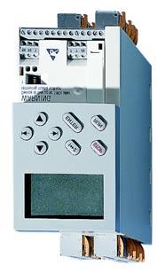
1 EDK2173DB.50G Ä.50Gä Montageanleitung Mounting Instructions Instructions de montage Systembus (CAN) Prod.-No. L EMF2173.1A EMF2173IB, EMF2173IB V002, EMF2173IB V003 PC Systembusadapter PC system bus adapter L adaptateur bus système pour PC
2 Lesen Sie zuerst diese Anleitung und die Dokumentation zum Grundgerät, bevor Sie mit den Arbeiten beginnen! Beachten Sie die enthaltenen Sicherheitshinweise. Please read these instructions and the documentation of the standard device before you start working! Observe the safety instructions given therein! Lire le présent fascicule et la documentation relative à l appareil de base avant toute manipulation de l équipement! Respecter les consignes de sécurité fournies.

3 Prod.-No. L EMF2173.1A 2173PC_001
4 Legende zur Abbildung auf der Ausklappseite Spannungsadapter für Tastaturanschluss für EMF2173IB: Ausführung mit DIN Stecker für EMF2173IB V002 / V003: Ausführung mit PS2 Stecker Verbindungskabel (Leitungslänge ca. 900 mm) Anschluss an parallele Schnittstelle LPTx Tastaturkabel mit Stecker Anschluss an Tastatureingang Sub D Stecker mit 3 poligem Kabel Verwenden Sie die im Lieferumfang enthaltenen grauen/grünen Stecker bzw. den grünen Adapter für folgende Antriebsregler: 3 poliger grüner Adapter: Frequenzumrichter 8200 vector mit Funktionsmodul E82ZAFC 4 poliger grüner Stecker: Frequenzumrichter 8200 vector mit Kommunikationsmodul 2171/ poliger grauer Stecker: Servo Umrichter 93XX, 9300 Servo PLC Servo Drives 9400 Servo Umrichter 93XX, 9300 Servo PLC Servosystem ECS Bitte den im Lieferumfang des Antriebsreglers enthaltenen Stecker verwenden. Drive PLC Bitte den im Lieferumfang des Antriebsreglers enthaltenen Stecker verwenden. Frequenzumrichter 8200 vector ohne Abbildung Frequenzumrichter 82XX mit Kommunikationsmodul Typ 2171 oder Typ 2172: 4 poligen grünen Stecker verwenden! mit Kommunikationsmodul Typ 2175 oder Typ 2178: 5 poligen grünen Stecker verwenden, der im Lieferumfang des Kommunikationsmoduls enthalten ist! siehe 10 0Abb. 0Tab. 0 Tipp! Aktuelle Dokumentationen und Software Updates zu Lenze Produkten finden Sie im Internet jeweils im Bereich "Services & Downloads" unter 4 EDK2173DB DE/EN/FR 5.1
5 Gültigkeit Diese Anleitung ist gültig für ƒ PC Systembusadapter EMF2173IB (alle Varianten) ab Version 1A. Diese Anleitung ist nur gültig zusammen mit der zugehörigen Betriebsanleitung der für den Einsatz zulässigen Busteilnehmer. Identifikation L 2173PC 003 EMF2173IB 1A XX 00x Gerätereihe Hardwarestand Softwarestand Variante DIN Tastaturanschluss 002 PS2 Tastaturanschluss 003 PS2 Tastaturanschluss mit galvanischer Trennung Funktion ƒ Parametrierung der Servo Umrichter 93XX Servo Drives 9400 Servosystem ECS Frequenzumrichter 82XX und 8200 vector ƒ Parametrierung des I/O System IP 20 ƒ Programmierung der 9300 Servo PLC ƒ Programmierung der Drive PLC ƒ Inbetriebnahme dieser Geräte EDK2173DB DE/EN/FR 5.1 5
6 i Inhalt 1 Sicherheitshinweise Definition der verwendeten Hinweise Restgefahren Lieferumfang Elektrische Installation Technische Daten EDK2173DB DE/EN/FR 5.1
7 Sicherheitshinweise Definition der verwendeten Hinweise 1 1 Sicherheitshinweise Definition der verwendeten Hinweise Um auf Gefahren und wichtige Informationen hinzuweisen, werden in dieser Dokumentation folgende Piktogramme und Signalwörter verwendet: Sicherheitshinweise Aufbau der Sicherheitshinweise: Gefahr! (kennzeichnet die Art und die Schwere der Gefahr) Hinweistext (beschreibt die Gefahr und gibt Hinweise, wie sie vermieden werden kann) Piktogramm und Signalwort Gefahr! Gefahr! Stop! Bedeutung Gefahr von Personenschäden durch gefährliche elektrische Spannung Hinweis auf eine unmittelbar drohende Gefahr, die den Tod oder schwere Verletzungen zur Folge haben kann, wenn nicht die entsprechenden Maßnahmen getroffen werden. Gefahr von Personenschäden durch eine allgemeine Gefahrenquelle Hinweis auf eine unmittelbar drohende Gefahr, die den Tod oder schwere Verletzungen zur Folge haben kann, wenn nicht die entsprechenden Maßnahmen getroffen werden. Gefahr von Sachschäden Hinweis auf eine mögliche Gefahr, die Sachschäden zur Folge haben kann, wenn nicht die entsprechenden Maßnahmen getroffen werden. EDK2173DB DE/EN/FR 5.1 7
8 1 Sicherheitshinweise Restgefahren Anwendungshinweise Piktogramm und Signalwort Hinweis! Tipp! Restgefahren Bedeutung Wichtiger Hinweis für die störungsfreie Funktion Nützlicher Tipp für die einfache Handhabung Verweis auf andere Dokumentation Gefahr! Beachten Sie die in den Anleitungen zum Antriebsregler bzw. der Antriebs SPS enthaltenen Sicherheitshinweise und Restgefahren. 8 EDK2173DB DE/EN/FR 5.1
9 Lieferumfang 2 2 Lieferumfang L 2173PC 004 Pos Lieferumfang EMF2173IB oder EMF2173IB V002 oder EMF2173IB V003 Verbindungskabel mit Sub D Stecker, 5m 3 poliger Stecker, grau 4 poliger Stecker, grün 3 poliger Adapter, grün, bestehend aus Stecker und Buchse Montageanleitung Zubehör (nicht im Lieferumfang enthalten) Stück Kommunikationsbaugruppe Bestellangaben 1 Kommunikationsmodul 2171 CAN oder 2172 CAN EMF2171IB oder EMF2172IB 1 Kommunikationsmodul 2175 CANopen EMF2175IB 1 Kommunikationsmodul 2178 CANopen EMF2178IB 1 Funktionsmodul CAN E82ZAFCCxxx 1 Funktionsmodul CANopen E82ZAFUC0xx 1 Stecker EWZ0046 EDK2173DB DE/EN/FR 5.1 9
10 3 Elektrische Installation 3 Elektrische Installation Verbindung zwischen PC/Notebook und Servo Drives 9400 ( ) herstellen (siehe Ausklappseite) 1. Verbinden Sie einen Sub D Stecker (z. B. Typ EWZ0046 von Lenze) mit einem von der CiA Organisation (CAN in Automation) spezifizierten Kabel. 2. Stecken Sie zur Verbindung zwischen Antriebsregler und Systembusadapter diesen Sub D Stecker auf den Anschluss des Antriebsreglers. 3. Verbinden Sie den im Lieferumfang enthaltenen Sub D Stecker mit dem anderen Ende des Kabels. 4. Stellen Sie die Verbindung mit dem Systembusadapter her. Verbindung zwischen PC/Notebook und übrigen Antriebsreglern ( ) herstellen (siehe Ausklappseite) 1. PC Systembusadapter 2173 auf die parallele Schnittstelle des PC/Notebook stecken. 2. PS2/DIN Tastaturstecker des PC/Notebook mit dem Spannungsadapter verbinden. 3. Spannungsadapter in den Tastatureingang des PC/Notebook stecken. 4. Das am Sub D Stecker angeschlossene 3 polige Kabel mit dem Stecker für das anzuschließende Gerät entsprechend den aufgedruckten Beschriftungen verbinden (Auswahl siehe Abbildung). 5. Stecker in die dafür vorgesehene Buchse des anzuschließenden Gerätes stecken. 6. Sub D Stecker in den PC Systembusadapter stecken. 10 EDK2173DB DE/EN/FR 5.1
11 Elektrische Installation 3 Belegung des Sub D Steckers Ansicht Pin Steckerbelegung 1) Verbindung herstellen zwischen Kabellitze Klemmenleiste V / +5V nicht belegt 2 CAN LO weiß LO 3 CAN GND grün GND 4 nicht belegt 5 nicht belegt 6 CAN GND nicht belegt 7 CAN HI braun HI 8 nicht belegt 9 +12V / +5V nicht belegt 1) Im mitgelieferten Sub D Stecker ist ein Abschlusswiderstand von 120 integriert. Der Sub D Stecker entspricht der Empfehlung DS von CiA. EDK2173DB DE/EN/FR
12 4 Technische Daten 4 Technische Daten Buslänge In Abhängigkeit der eingestellten Datenübertragungsgeschwindigkeit sind bei einem CAN Bus (Netzwerktopologie: Linie) folgende Distanzen nicht zu überschreiten: Übertragungsrate [kbit/s] EMF2173IB / EMF2173IB V002 Max. Buslänge [m] EMF2173IB V Stromaufnahme Die Stromaufnahme des PC Systembusadapters erfolgt über den PS2 bzw. DIN Tastaturanschluss. Sie ist abhängig von der Variante des PC Systembusadapters: Variante EMF2173IB EMF2173 V002 EMF2173IB V003 Stromaufnahme max. 150 ma typisch 60 ma max. 180 ma typisch 80 ma Spezifikation des Übertragungskabels Verwenden Sie den von der CiA Organisation (CAN in Automation) spezifizierten Kabeltyp. 12 EDK2173DB DE/EN/FR 5.1
13 Technische Daten 4 EDK2173DB DE/EN/FR
14 Legend for fold out page Voltage adapter for keyboard connection for EMF2173IB: design with DIN plug for EMF2173IB V002 / V003: design with PS2 plug Connection cable (cable length approx. 900 mm) Connection to parallel LPTx interface Keyboard cable with plug Connection to keyboard input Sub D plug with 3 pole cable Use the grey/green plugs or the green adapter contained in the scope of supply for the following controllers: Green 3 pole adapter: 8200 vector frequency inverter with E82ZAFC function module Green 4 pole plug: 8200 vector frequency inverter with 2171/2172communication module Grey 3 pole plug: 93XX servo inverter, 9300 servo PLC 9400servo drives 93XX servo inverter, 9300 servo PLC ECS servo system Please use the plug contained in the scope of supply of the controller. Drive PLC Please use the plug contained in the scope of supply of the controller vector frequency inverter Witho 82XX frequency inverter ut with communication module of type 2171 or 2172: illustr Use green 4 pole plug! ation with communication module of type 2175 or 2178: Use green 5 pole plug contained in the scope of supply of the communication module! See 20 0Fig. 0Tab. 0 Tip! Current documentation and software updates concerning Lenze products can be found on the Internet in the "Services & Downloads" area under 14 EDK2173DB DE/EN/FR 5.1
15 Validity These instructions are valid for ƒ EMF2173IB PC system bus adapters (all variants) as of version 1A. These instructions are only valid together with the Operating Instructions for the nodes used for your application. Identification L 2173PC 003 EMF2173IB 1A XX 00x Series Hardware version Software version Variant DIN keyboard connection 002 PS2 keyboard connection 003 PS2 keyboard connection with isolation Function ƒ Parameterisation of the 93XX servo inverters 9400 servo drives ECS servo system 82XX and 8200 vector frequency inverters ƒ Parameterisation of the IP 20 I/O system ƒ Programming of the 9300 servo PLC ƒ Programming of the drive PLC ƒ Commissioning of these devices EDK2173DB DE/EN/FR
16 i Contents 1 Safety instructions Definition of notes used Residual hazards Scope of supply Electrical installation Technical data EDK2173DB DE/EN/FR 5.1
17 Safety instructions Definition of notes used 1 1 Safety instructions Definition of notes used The following pictographs and signal words are used in this documentation to indicate dangers and important information: Safety instructions Structure of safety instructions: Danger! (characterises the type and severity of danger) Note (describes the danger and gives information about how to prevent dangerous situations) Pictograph and signal word Danger! Danger! Stop! Meaning Danger of personal injury through dangerous electrical voltage. Reference to an imminent danger that may result in death or serious personal injury if the corresponding measures are not taken. Danger of personal injury through a general source of danger. Reference to an imminent danger that may result in death or serious personal injury if the corresponding measures are not taken. Danger of property damage. Reference to a possible danger that may result in property damage if the corresponding measures are not taken. EDK2173DB DE/EN/FR
18 1 Safety instructions Residual hazards Application notes Pictograph and signal word Note! Tip! Residual hazards Meaning Important note to ensure troublefree operation Useful tip for simple handling Reference to another documentation Danger! Observe the safety instructions and residual hazards mentioned in the Operating Instructions for the controller or drive PLC. 18 EDK2173DB DE/EN/FR 5.1
19 Scope of supply 2 2 Scope of supply L 2173PC 004 Pos Scope of delivery EMF2173IB or EMF2173IB V002 or EMF2173IB V003 Connection cable with Sub D plug, 5m 3 pole plug, grey 4 pole plug, green 3 pole adapter, green, consisting of a plug and socket Mounting Instructions Accessories (not contained in the scope of supply) Item Communication module Ordering information CAN or 2172 CAN communication module EMF2171IB or EMF2172IB CANopen communication module EMF2175IB CANopen communication module EMF2178IB 1 CAN E82ZAFCCxxx 1 CANopen function module E82ZAFUC0xx 1 Plug EWZ0046 EDK2173DB DE/EN/FR
20 3 Electrical installation 3 Electrical installation Establishing the connection between PC/notebook and 9400 servo drives ( ) (see fold out page) 1. Connect a Sub D plug (e. g. type EWZ0046 by Lenze) to a cable specified by the CiA organisation (CAN in automation). 2. For the connection between the controller and the system bus adapter, attach this Sub D plug to the connection of the controller. 3. Connect the Sub D plug contained in the scope of supply to the other end of the cable. 4. Establish the connection to the system bus adapter. Establishing the connection between PC/notebook and other controllers ( ) (see fold out page) 1. Attach the 2173 PC system bus adapter to the parallel interface of the PC/notebook. 2. Connect the PS2/DIN keyboard connector of the PC/notebook to the voltage adapter. 3. Plug the voltage adapter into the keyboard input of the PC/notebook. 4. Connect the 3 pole cable that is connected to the Sub D plug with the plug for the device to be connected according to the imprinted labelling (for selection see illustration). 5. Insert the plug in the socket of the device to be connected, which is provided for this purpose. 6. Plug Sub D plug into the PC system bus adapter. 20 EDK2173DB DE/EN/FR 5.1
21 Electrical installation 3 Assignment of Sub D plug View Pin Connector assignment 1) Establish connection between cable strand terminal strip 1 +12V / +5V Not assigned 2 CAN LO white LO 3 CAN GND green GND 4 Not assigned 5 Not assigned 6 CAN GND Not assigned 7 CAN HI brown HI 8 Not assigned 9 +12V / +5V Not assigned 1) In the Sub D plug supplied, a terminating resistor of 120 is integrated. The Sub D plug corresponds to recommendation DS by CiA. EDK2173DB DE/EN/FR
22 4 Technical data 4 Technical data Bus length Depending on the data transmission speed set, the following distances may not be exceeded in the case of a CAN bus (network topology: line): Baud rate [kbps] EMF2173IB / EMF2173IB V002 Max. bus length [m] EMF2173IB V Current consumption The current consumption of the PC system bus adapter is effected via the PS2 or DIN keyboard connection. It depends on the variant of the PC system bus adapter: Variant EMF2173IB EMF2173 V002 EMF2173IB V003 Current consumption Max. 150 ma Typically 60 ma Max. 180 ma Typically 80 ma Specification of the transmission cable Use the cable type specified by the CiA organisation (CAN in automation). 22 EDK2173DB DE/EN/FR 5.1
23 Technical data 4 EDK2173DB DE/EN/FR
24 Légende de l illustration de la page dépliante Adaptateur de tension pour raccordement du clavier Pour EMF2173IB : version avec connecteur DIN Pour EMF2173IB V002 / V003 : version avec connecteur PS2 Câble de liaison (longueur de câble : 900 mm env.) Raccordement à l inteface parallèle LPTx Câble du clavier avec connecteur Raccordement au port du clavier Connecteur SUB D mâle avec câble tripolaire Utiliser les connecteurs gris/verts fournis ou l adaptateur vert pour les variateurs suivants : Adaptateur tripolaire vert : Convertisseurs de fréquence 8200 vector avec module de fonction E82ZAFC Connecteur 4 pôles vert : Convertisseurs de fréquence 8200 vector avec module de communication 2171/2172 Connecteur tripolaire gris : Servovariateurs 93XX, 9300 Servo PLC Servovariateurs 9400 Servovariateurs 93XX, 9300 Servo PLC Système servo ECS Prière d utiliser le connecteur fourni avec le variateur. Drive PLC Prière d utiliser le connecteur fourni avec le variateur. Convertisseur de fréquence 8200 vector Pas d illus tratio n Convertisseur de fréquence 82XX Avec un module de communication de type 2171 ou 2172 : Utiliser le connecteur 4 pôles vert. Avec un module de communication de type 2175 ou 2178 : Utiliser le connecteur 5 pôles vert fourni avec le module de communication. Voir 30 0Fig. 0Tab. 0 Conseil! Les mises à jour de logiciels et les documentations récentes relatives aux produits Lenze sont disponibles dans la zone "Téléchargements" du site Internet : 24 EDK2173DB DE/EN/FR 5.1
25 Validité Le présent document s applique au produit suivant : ƒ Adaptateurs Bus Système pour PC EMF2173IB (toutes variantes) à partir de la version 1A. Cette documentation n est valable que conjointement avec les instructions de mise en service des participants au bus admis. Identification L 2173PC 003 EMF2173IB 1A XX 00x Série d appareils Version matérielle Version logicielle Variante Raccordement clavier DIN 002 Raccordement clavier PS2 003 Raccordement clavier PS2 avec isolation galvanique Fonction ƒ Paramétrage du servovariateur 93XX des servovariateurs 9400 du servosystème ECS des convertisseurs de fréquence 82XX et 8200 vector ƒ Paramétrage du système E/S IP 20 ƒ Programmation du 9300 Servo PLC ƒ Programmation du Drive PLC ƒ Mise en service de ces appareils EDK2173DB DE/EN/FR
26 i Sommaire 1 Consignes de sécurité Définition des conventions utilisées Dangers résiduels Equipement livré Installation électrique Spécifications techniques EDK2173DB DE/EN/FR 5.1
27 Consignes de sécurité Définition des conventions utilisées 1 1 Consignes de sécurité Définition des conventions utilisées Pour indiquer des risques et des informations importantes, la présente documentation utilise les mots et symboles suivants : Consignes de sécurité Présentation des consignes de sécurité Danger! (Le pictogramme indique le type de risque.) Explication (L explication décrit le risque et les moyens de l éviter.) Pictogramme et mot associé Danger! Danger! Stop! Explication Situation dangereuse pour les personnes en raison d une tension électrique élevée Indication d un danger imminent qui peut avoir pour conséquences des blessures mortelles ou très graves en cas de non respect des consignes de sécurité correspondantes Situation dangereuse pour les personnes en raison d un danger d ordre général Indication d un danger imminent qui peut avoir pour conséquences des blessures mortelles ou très graves en cas de non respect des consignes de sécurité correspondantes Risques de dégâts matériels Indication d un risque potentiel qui peut avoir pour conséquences des dégâts matériels en cas de non respect des consignes de sécurité correspondantes EDK2173DB DE/EN/FR
28 1 Consignes de sécurité Dangers résiduels Consignes d utilisation Pictogramme et mot associé Remarque importante! Conseil! Dangers résiduels Explication Remarque importante pour assurer un fonctionnement correct Conseil utile pour faciliter la mise en oeuvre Référence à une autre documentation Danger! Tenir compte des consignes de sécurité contenues dans la documentation sur le variateur de vitesse ou de l API, ainsi que des dangers résiduels décrits. 28 EDK2173DB DE/EN/FR 5.1
29 Equipement livré 2 2 Equipement livré L 2173PC 004 Pos. Equipement livré EMF2173IB ou EMF2173IB V002 ou EMF2173IB V003 Câble de liaison avec connecteur SUB D mâle, 5 m Connecteur tripolaire, gris Connecteur 4 pôles, vert Adaptateur tripolaire, vert, composé d un connecteur et d une prise Instructions de montage Accessoires (non fournis) Pièce Module de communication Réf. de commande 1 Module de communication 2171 CAN ou 2172 CAN EMF2171IB ou EMF2172IB 1 Module de communication 2175 CANopen EMF2175IB 1 Module de communication 2178 CANopen EMF2178IB 1 Module de fonction CAN E82ZAFCCxxx 1 Module de fonction CANopen E82ZAFUC0xx 1 Connecteur EWZ0046 EDK2173DB DE/EN/FR
30 3 Installation électrique 3 Installation électrique Etablissement de la liaison entre le PC / l ordinateur portable et les servovariateurs 9400 ( ) (voir page dépliante) 1. Raccorder un connecteur SUB D mâle (par ex. de type EWZ0046 de Lenze) à un câble spécifié par l organisation CiA (CAN in Automation). 2. Pour relier le variateur et l adaptateur Bus Système, enficher ce connecteur SUB D mâle sur le raccord du variateur. 3. Raccorder ensuite le connecteur SUB D mâle fourni à l autre extrémité du câble. 4. Relier l adaptateur pour Bus Système. Etablissement de la liaison entre le PC / l ordinateur portable et les autres variateurs de vitesse ( ) (voir page dépliante) 1. Enficher l adaptateur Bus Système pour PC 2173 sur le port parallèle du PC / de l ordinateur portable. 2. Relier le connecteur du clavier PS2/DIN du PC / de l ordinateur portable à l adaptateur de tension. 3. Enficher l adaptateur de tension sur le port du clavier du PC / de l ordinateur. 4. Relier le câble tripolaire du connecteur SUB D mâle à la prise de l appareil à raccorder en se référant au marquage imprimé (voir illustration). 5. Enficher le connecteur sur la prise adaptée de l appareil à raccorder. 6. Enficher le connecteur SUB D mâle sur l adaptateur Bus Système pour PC. 30 EDK2173DB DE/EN/FR 5.1
31 Installation électrique 3 Affectation du connecteur SUB D mâle Affichage Bro che Affectation des connecteurs 1) Etablir une liaison entre tresse de câble bornier V / +5 V non affecté 2 CAN LO blanche LO 3 CAN GND verte GND 4 non affecté 5 non affecté 6 CAN GND non affecté 7 CAN HI brune HI 8 non affecté V / +5 V non affecté 1) Une résistance d extrémité de 120 est intégrée au connecteur SUB D mâle. Le connecteur SUB D mâle est conforme à la recommandation DS de l organisation CiA. EDK2173DB DE/EN/FR
32 4 Spécifications techniques 4 Spécifications techniques Longueur du bus En fonction de la vitesse de transmission des données réglée, il convient de ne pas dépasser les distances suivantes pour un Bus CAN (topologie du réseau : ligne) : Vitesse de transmission [kbits/s] EMF2173IB / EMF2173IB V002 Longueur de bus maxi. [m] EMF2173IB V Courant absorbé Le courant absorbé par l adaptateur Bus Système pour PC passe par le raccordement clavier PS2 ou DIN. Il varie en fonction du type d adaptateur Bus Système pour PC utilisé : Variante EMF2173IB EMF2173 V002 EMF2173IB V003 Courant absorbé Valeur maximale : 150 ma Cas général : 60 ma Valeur maximale : 180 ma Cas général : 80 ma Spécifications pour câble de transmission Utiliser le type de câble spécifié par l organisation CiA (CAN in Automation). 32 EDK2173DB DE/EN/FR 5.1
33 Spécifications techniques 4 EDK2173DB DE/EN/FR
34 12/2010 Lenze Drives GmbH Postfach D Hameln Germany Service Lenze Service GmbH Breslauer Straße 3 D Extertal Germany +49(0)5154/ / (24 h helpline) +49(0)5154/ (0)5154/ Lenze@Lenze.de Service@Lenze.de EDK2173DB.50G DE/EN/FR 5.1 TD
Ä.>o:ä. Systembus (CAN) Montageanleitung Mounting Instructions Instructions de montage EMF2177IB
 Montageanleitung Mounting Instructions Instructions de montage EMF2177IB") EDK2177DB.>o: Ä.>o:ä Montageanleitung Mounting Instructions Instructions de montage Systembus (CAN) EMF2177IB PC Systembusadapter (USB) PC system bus adapter (USB) L adaptateur bus système (USB) Lesen
EDK2177DB.>o: Ä.>o:ä Montageanleitung Mounting Instructions Instructions de montage Systembus (CAN) EMF2177IB PC Systembusadapter (USB) PC system bus adapter (USB) L adaptateur bus système (USB) Lesen
PC-Systembusmodul 2173
 EDK273DB 00424094 09/0 PC-Systembusmodul 273 Diese Anleitung beschreibt die Handhabung und die Installation des PC-Systembusmoduls enthält die wichtigsten technischen Daten des PC-Systembusmoduls ist gültig
11 kw** E82MV222_4B kw**
 EDK82ZWKN4 00459189 10/02 Netzschleifklemme Typ E82ZWKN4 Diese Anleitung enthält wichtige Hinweise für den Einsatz der Netzschleifklemme E82ZWKN4 und beschreibt deren Montage. ist nur gültig - für Netzschleifklemmen
Halterung E71ZJ001 Montagesatz FIF für starttec
 EDK71ZJ001 00477234 11/03 Halterung E71ZJ001 Montagesatz FIF für starttec Diese Anleitung beschreibt die mechanische Installation der Halterung E71ZJ001 im starttec ist nur gültig zusammen mit der Montageanleitung
Filter Typ 3~ RFI Filter I0FAExxxF100DxxxxS
 Typennummer I0FAE3xxF100XxxxxS RFI Filter I0FAE4xxF100XxxxxS Filter Typ 3~ RFI Filter I0FAExxxF100DxxxxS Technische Daten Typ E355F E375F E411F 100D... 100D... 100D... Bemessungsstrom [A] 120.0 / 105.0
Ä.6Shä CAN. Montageanleitung Mounting Instructions Instructions de montage EMF2176IB. CAN-Repeater CAN repeater Répétiteur CAN. EDKMF2176X.
 HI EDKMF2176X.6Sh Ä.6Shä CAN Montageanleitung Mounting Instructions Instructions de montage 1 2 24V GND 3 4 5 LO GND L Hans-Lenze-Straße 1 D31855 Aerzen Made in Germany Type EMF2176IB Id.-No. Prod.-No.
Montageanleitung / Mounting instruction / Manuel de montage. D: Abmessung bis zur Klemme. Mat. Nr Typennummer
 Typennummer RFI Filter I0FAE3xxF100XxxxxS Filter Typ 3~ RFI Filter I0FAE3xxF100XxxxxS Technische Daten Typ E330F E337F E345F 100D 100D 100D Bemessungsstrom [A] 55.00/45.70 69.00/57.00 100.00/86.00 Ableitstrom
Entwurf. preliminary
 KAPRi plus Erweiterungsset M12 KAPRi plus Extension Kit M12 KAPRi plus Kit d Extension M12 Bedienungsanleitung / User instructions / Instructions d installation 899366 KAPRi plus Erweiterungsset M12 /
L Ä!O`pä. Montageanleitung Mounting Instructions Instructions de montage
 EDKLD3-001!Oòp L Ä!O`pä D GB F Montageanleitung Mounting Instructions Instructions de montage 1U2 1V2 1W2 Global Drive ELD3-001Hxxx Lagerstromdrossel Bearing current-limiting choke Self de protection pour
i500 Sicherheitsmodul I5MASA000 I5MASA000 safety module Montageanleitung Mounting Instructions
 i500 Sicherheitsmodul I5MASA000 Montageanleitung I5MASA000 safety module Mounting Instructions Allgemeines Erst lesen, dann beginnen 1 1 Allgemeines 1.1 Erst lesen, dann beginnen Lesen Sie vor der Installation
Ä.5ù7ä. Montageanleitung Mounting Instructions Instructions de montage E82ZWBRB
 EDK82ZWBRB.5ù7 Ä.5ù7ä Montageanleitung Mounting Instructions Instructions de montage E82ZWBRB Elektronischer Bremsenschalter AC 230 V (DC 205 V) Electronic brake switch AC 230 V (DC 205 V) Contacteur de
Diagramm 1 2 A [mm] B [mm] C [mm] D [mm] Abmessungen
![Diagramm 1 2 A [mm] B [mm] C [mm] D [mm] Abmessungen](/thumbs/98/137025716.jpg "Diagramm 1 2 A [mm] B [mm] C [mm] D [mm] Abmessungen") Typennummer RFI Filter I0FAE3xxF100XxxxxS Filter Typ 3~ RFI Filter I0FAE3xxF100XxxxxS Technische Daten Typ E311F E322F E345F 100D... 100S... 100D 100D Bemessungsstrom [A] 29.00 / 22.6 55.00/46.00 100.00/86.00
Typennummer RFI Filter I0FAE3xxF100XxxxxS Filter Typ 3~ RFI Filter I0FAE3xxF100XxxxxS Technische Daten Typ E311F E322F E345F 100D... 100S... 100D 100D Bemessungsstrom [A] 29.00 / 22.6 55.00/46.00 100.00/86.00
Montageanleitung / Mounting instruction / Manuel de montage. D: Abmessung bis zur Klemme. Mat. Nr Typennummer
 Typennummer RFI Filter I0FAE1xxX100XxxxxS Filter Typ 1~ RFI Filter I0FAE1xxB100XxxxxS 3~ RFI Filter I0FAE1xxF100XxxxxS Technische Daten Typ E137B E175B E175F 100L... 100L... 100S... 100D... 100S... 100D...
Montageanleitung / Mounting instruction / Manuel de montage. D: Abmessung bis zur Klemme. Mat. Nr Typennummer
 Typennummer RFI Filter I0FAE3xxF100XxxxXS Filter Typ 3~ RFI Filter I0FAE3xxF100XxxxXS Technische Daten Typ E311F E318F E322F 100D... 100S... 100D... 100D0000S 100D0001S Bemessungsstrom [A] 29.00 / 22.6
Montageanleitung Installation instructions Notice de montage. AS-i Modul AS-i module Module AS-i AC2480
 Montageanleitung Installation instructions Notice de montage AS-i Modul AS-i module Module AS-i AC2480 Sachnr. 701509/02 01/2005 Bestimmungsgemäße Verwendung AS-i-Profil S-0.A.E maximale Anzahl von Modulen
E : USB, Typ Mini-B (Buchse) 2: LED Betriebszustand 3: 24 V DC 4: Fehler / CH2 (DI/DO) / CH1 (C/Q)
 2: LED Betriebszustand 3: 24 V DC 4: Fehler / CH2 (DI/DO) / CH1 (C/Q)") Parametriersysteme : USB, Typ Mini-B (Buchse) 2: LED Betriebszustand 3: 24 V DC 4: Fehler / CH2 (DI/DO) / CH (C/Q) Produktmerkmale USB IO-Link Master zum Parametrieren und Analysieren von Geräten Unterstützte
Parametriersysteme : USB, Typ Mini-B (Buchse) 2: LED Betriebszustand 3: 24 V DC 4: Fehler / CH2 (DI/DO) / CH (C/Q) Produktmerkmale USB IO-Link Master zum Parametrieren und Analysieren von Geräten Unterstützte
Ä.RUWä CAN. Montageanleitung Mounting Instructions Instructions de montage EMF2174IB
 EDK2174DB.RUW Ä.RUWä CAN Montageanleitung Mounting Instructions Instructions de montage EMF2174IB CAN Adressierungsmodul CAN addressing module Module d adressage CAN Vorwort und Allgemeines 0Abb. 0Tab.
Betriebsanleitung AC-4703
 28 mm 47 mm Dokumentenstückliste C105395.001 BNC- Stecker 1 BNC- Stecker 2 BNC- Stecker 3 BNC- Stecker 4 Betriebsanleitung Adapterkabel Abbildung 1) Adapterkabel Anwendung Das Adapterkabel wird benötigt,
Feldbusmodul Das Feldbusmodul 2141 ermöglicht die Kommunikation mit Lenze-Antriebsreglern über LON.
 EDK2141DB 00417292 10/00 Feldbusmodul 2141 LON (Local Operating Network) Diese Anleitung é enthält die wichtigsten Technischen Daten. é beschreibt die Installation des Feldbusmoduls. é ist ein Auszug aus
Einbauanleitung Komfort CAN Bus Interface 62240
 Einbauanleitung Komfort CAN Bus Interface 62240 Wichtiger Hinweis vor dem Einbau: Bitte beachten Sie generell beim Einbau von elektronischen Baugruppen in Fahrzeugen die Einbaurichtlinien und Garantiebestimmungen
Ä.C1bä CAN. Montageanleitung Mounting Instructions Instructions de montage E82ZAFCC001. Funktionsmodul Function module Module de fonction
 EDK82ZAFCC 001.C1b Ä.C1bä CAN Montageanleitung Mounting Instructions Instructions de montage E82ZAFCC001 Funktionsmodul Function module Module de fonction Lesen Sie zuerst diese Anleitung und die Dokumentation
Electrical testing of Bosch common rail piezo injectors
 Applies to generation CRI 3: Bosch 10-position order number 0 445 115 = CRI 3-16 (CRI 3.0) 1600 bar 0 445 116 = CRI 3-18 (CRI 3.2) 1800 bar 0 445 117 = CRI 3-20 (CRI 3.3) 2000 bar Tools required: Hybrid
Hama GmbH & Co KG D Monheim/Germany
 Hama GmbH & Co KG D-86651 Monheim/Germany www.hama.com All listed brands are trademarks of the corresponding companies. Errors and omissions excepted, and subject to technical changes. Our general terms
Ä.R3wä CAN PT. Montageanleitung Mounting Instructions Instructions de montage E82ZAFCC010. Funktionsmodul Function module Module de fonction
 EDK82ZAFCC 010.R3w Ä.R3wä CAN PT Montageanleitung Mounting Instructions Instructions de montage E82ZAFCC010 Funktionsmodul Function module Module de fonction Lesen Sie zuerst diese Anleitung und die Dokumentation
Ä.51#ä. Systembus (CAN) PT. Montageanleitung Mounting Instructions Instructions de montage E82ZAFCC010
 PT. Montageanleitung Mounting Instructions Instructions de montage E82ZAFCC010") EDK82ZAFCC 010.51# Ä.51#ä Montageanleitung Mounting Instructions Instructions de montage Systembus (CAN) PT E82ZAFCC010 Funktionsmodul Function module Module de fonction Lesen Sie zuerst diese Anleitung
EDK82ZAFCC 010.51# Ä.51#ä Montageanleitung Mounting Instructions Instructions de montage Systembus (CAN) PT E82ZAFCC010 Funktionsmodul Function module Module de fonction Lesen Sie zuerst diese Anleitung
Decoderprogrammiermodul
 Decoderprogrammiermodul 55045 2 Inhaltsverzeichnis: Seite Systemvoraussetzungen 4 Sicherheitshinweise 4 Aufbau 4 Installation 4 Anschluss 8 Sommaire : Page Matériel requis 6 Indications relatives à la
RZ 041. LISTED Control Nr.:95D1 Test Accessories. Isoprobe II 1:1. Benutzerinformation User Information Information pour l utilisateur
 RZ 041 LISTED Control Nr.:95D1 Test Accessories Isoprobe II 1:1 Benutzerinformation User Information Information pour l utilisateur Bemessungsspannung / Rated voltage / Tension assignée Isoprobe II - 1:1
PROFIBUS-DP Repeater 1 to 1 and 1 to 5 with optional level converter module
 LSS PROFIBUS-DP Repeater 1 to 1 and 1 to 5 with optional level converter module The LSS PROFIBUS-DP repeaters 1 to 1 and 1 to 5 are used for coupling up to six PROFIBUS bus segments in RS 485 bus technology.
150-in-1. Handbuch / Manual / Manuel. Externer Card Reader USB 2.0
 Handbuch / Manual / Manuel Vielen Dank, dass Sie sich für ein Produkt von ultron entschieden haben. Wir wünschen Ihnen viel Freude mit Ihrem neuen Gerät! CE-Erklärung und Hinweise Hiermit erklärt die
VN7640 FlexRay/CAN/LIN/Ethernet Interface Quick Start Guide. Version 1.1 English/Deutsch
 VN7640 FlexRay/CAN/LIN/Ethernet Interface Quick Start Guide Version 1.1 English/Deutsch Quick Start Guide VN7640 ENGLISH 1 ENGLISH 1.1 Installation Step by Step Procedure Please use the drivers from the
Electrical testing of Bosch common rail Injectors
 Electrical testing of Bosch common rail Injectors Contents: 1. Adapter cable for Hybridtester FSA 050 (article number 0 684 010 050 / 1 687 023 571) 2. Electrical testing of Bosch common rail solenoid
12 V-Stecker / 12 V plug / Prise 12 V
 emergency 12 V-Stecker / 12 V plug / Prise 12 V für / for / pour Ladeschnittstelle BASE STATION Verbindungsleitung ACCUVAC BASE STATION charger interface ACCUVAC connecting cable Interface de charge BASE
Montageanleitung Assembly instructions Notice de montage
 Anschluss an 12 V-Bordnetz / Connection to the 12 V on-board power supply / Raccordement du câble au réseau de bord 12 V für / for / pour Ladeschnittstelle BASE STATION / Verbindungsleitung ACCUVAC / Verbindungsleitung
60 min WEBER INDUSTRIES. FAB /xx xxxxsxx MERTWILLER MOD.: LOT.:
 IMPORTANT - Notice à lire attentivement et à conserver pour consultation ultérieure. IMPORTANT - Read carefully Instructions and keep for future reference. WIHTIG - Anweisungen sorgfältig lesen und für
DTE910. Produktmerkmale RFID-UHF-Reader Quaderförmig Kunststoff M12-Steckverbindung Einsatzbereich. RFID Auswerteeinheit mit EtherNet/IP-Schnittstelle
 Identifikationssysteme Produktmerkmale RFID-UHF-Reader Quaderförmig Kunststoff M12-Steckverbindung Einsatzbereich Einsatzbereich Elektrische Daten Betriebsspannung [V] Stromaufnahme [ma] Arbeitsfrequenz
Programmieranleitung CADAS 100 LPG 210
 Programmieranleitung CADAS 100 LPG 210 Küvetten-Test LCK 555 Seite 1 BSB 5 BSB [n] Ausgabe 9804 Achtung! Das Ausgabedatum dieser Programmieranleitung muß mit dem Ausgabedatum der Arbeitsvorschrift der
Bedienungsanleitung User Manual. PCMCIA Reader B1
 Bedienungsanleitung User Manual PCMCIA Reader B1 Einführung Introduction Vielen Dank, dass Sie sich für ein KOBIL Smart Card Terminal entschieden haben. Mit dem KOBIL PCMCIA Reader B1 haben Sie ein leistungsfähiges
ma/hart-two-wire ma/hart-four-wire Profibus PA Foundation Fieldbus Modbus PLICSMOBILE. Document ID: 43634
 EU-Konformitätserklärung EU declaration of conformity Déclaration UE de conformité 61 62 63 65 66 67 68 4... 20 ma/hart-two-wire 4... 20 ma/hart-four-wire Profibus PA Foundation Fieldbus Modbus PLICSMOBILE
Ä.=#yä STANDARD I/O. Montageanleitung Mounting Instructions Instructions de montage E82ZAFSC / E82ZAFSC001
 EDK82ZAFSC.=#y Ä.=#yä Montageanleitung Mounting Instructions Instructions de montage STANDARD I/O E82ZAFSC / E82ZAFSC001 Funktionsmodul Function module Module de fonction Lesen Sie zuerst diese Anleitung
JX3-PS1. Installationsanleitung. Version Lieferumfang
 JX3-PS1 Spannungsversorgungsmodul Jetter AG Kontakte: Gräterstraße 2 E-Mail - Vertrieb: sales@jetter.de D-71642 Ludwigsburg E-Mail - Hotline: hotline@jetter.de Germany Telefon - Hotline: +49(0)7141/2550-444
Ä.UPjä. L force Communication INTERBUS
 EDK94AYCIB.UPj Ä.UPjä L force Communication INTERBUS Montageanleitung Mounting Instructions Instructions de montage Instrucciones para el montaje Istruzioni per il montaggio E94AYCIB Kommunikationsmodul
Ä.RLBä. L force Communication APPLICATION I/O. Montageanleitung Mounting Instructions Instructions de montage E82ZAFAC001
 EDK82ZAFAC 001.RLB Ä.RLBä L force Communication Montageanleitung Mounting Instructions Instructions de montage APPLICATION I/O E82ZAFAC001 Funktionsmodul Function module Module de fonction Lesen Sie zuerst
Description for the replacement of electronic controls for gas recovery
 Information on the replacement of the electronic control Description for the replacement of electronic controls for gas recovery Important information! The new electronic control for gas recovery with
iid software tools QuickStartGuide iid USB base driver installation
 iid software tools QuickStartGuide iid software tools USB base driver installation microsensys Nov 2016 Introduction / Einleitung This document describes in short form installation of the microsensys USB
Montageanleitung Installation Instructions Notice de Montage
 Montageanleitung Installation Instructions Notice de Montage R Reflexlichtschranke / Reflexlichttaster Retro-reflective sensor / Diffuse reflection sensor Système réflex / Système réflexion directe OE
Ä.6a9ä. Global Drive 30 A. Montageanleitung. Mounting Instructions. Instructions de montage EZN3B0110H030U
 EDKZN3B030.6a9 Ä.6a9ä Montageanleitung Mounting Instructions Instructions de montage Global Drive 30 A EZN3B0110H030U Unterbau Netzfilter Footprint mains filter Filtre réseau en montage arrière Lesen Sie
Electrical tests on Bosch unit injectors
 Valid for Bosch unit injectors with order numbers 0 414 700 / 0 414 701 / 0 414 702 Parts Kit Magnet*: - F00H.N37.925 - F00H.N37.933 - F00H.N37.934 * For allocation to the 10-place Bosch order number,
Programmieranleitung CADAS 100 LPG 158
 Kupfer Programmieranleitung CADAS 100 LPG 158 Küvetten-Test LCK 529 Seite 1 Ausgabe 98/04 Achtung! Das Ausgabedatum dieser Programmieranleitung muß mit dem Ausgabedatum der Arbeitsvorschrift der Reagenzien
Viatron GmbH Installationsanleitung KNX IR Linker
 Viatron GmbH Installationsanleitung KNX IR Linker Viatron GmbH Carl-Metz-Str. 3 76275 Ettlingen Tel.: +49 7243 5148 370 Fax: +49 7243 5148 351 Email: info@viatron.de Seite 1 von 5 Installationsanleitung
Ä.G\öä motec. Montageanleitung Mounting Instructions Instructions de montage E82ZBU
 EDK82ZBU.G\ö Ä.G\öä 8200 motec Montageanleitung Mounting Instructions Instructions de montage E82ZBU Schalter Poti Einheit Switch/potentiometer unit Unité potentiomètre interrupteur type Vorwort und Allgemeines
L Montageanleitung Assembly instructions Instruction de montage EASYHOMESYSTEM TH-EHS. Änderungen vorbehalten Alle Rechte vorbehalten
 L-09-1-50 Montageanleitung Assembly instructions Instruction de montage EASYHOMESYSTEM TH-EHS Änderungen vorbehalten Alle Rechte vorbehalten Komponenten / Components / Composants / Componenti PGD Touch
Zusatz zur Betriebsanleitung Addendum to the Operating Instructions
 Drive Technology \ Drive Automation \ System Integration \ Services Zusatz zur Betriebsanleitung Addendum to the Operating Instructions Austausch von MOVIGEAR -S01 durch MOVIGEAR -DSC-B Replacing MOVIGEAR
Programmieranleitung CADAS 100 LPG 158
 Wasserhärte Programmieranleitung CADAS 100 LPG 158 Küvetten-Test LCK 327 Seite 1 Ausgabe 97/06 Achtung! Das Ausgabedatum dieser Programmieranleitung muß mit dem Ausgabedatum der Arbeitsvorschrift der Reagenzien
Ä.R<Hä. L force Communication LECOM B. Montageanleitung Mounting Instructions Instructions de montage E82ZAFLC001
 EDK82ZAFLC 001.R
Ä.=#wä STANDARD I/O PT. Montageanleitung Mounting Instructions Instructions de montage E82ZAFSC010. Funktionsmodul Function module Module de fonction
 EDK82ZAFSC 010.=#w Ä.=#wä Montageanleitung Mounting Instructions Instructions de montage STANDARD I/O PT E82ZAFSC010 Funktionsmodul Function module Module de fonction Lesen Sie zuerst diese Anleitung und
Ä.GMNä. L-force Controls. Softwarehandbuch. Funktionsbibliothek "LenzeConversionBox" für Lenze-Software»Drive PLC Developer Studio«und»PLC Designer«
 EDSPLCLIB02 13384445 L-force Controls Ä.GMNä Softwarehandbuch Funktionsbibliothek "LenzeConversionBox" für Lenze-Software»Drive PLC Developer Studio«und»PLC Designer«L Inhalt Inhalt 1 Über diese Dokumentation.........................................................
Programmieranleitung CADAS 100 LPG 158
 Programmieranleitung CADAS 100 LPG 158 Ammonium-Stickstoff Küvetten-Test LCK 304 Seite 1 Ausgabe 98/04 Achtung! Das Ausgabedatum dieser Programmieranleitung muß mit dem Ausgabedatum der Arbeitsvorschrift
HEAG 151, 152, 153, 154 Digital Converter
 Montage- und Betriebsanleitung Installation and operating instructions MB095-11055704 Baumer_HEAG151-152-153-154_II_DE-EN (16A1) HEAG 151, 152, 153, 154 Digital Converter 1-2 Allgemeine Hinweise - Funktionsweise
HW 2.0.0, SW ma/hart-two-wire ma/hart-four-wire Profibus PA Foundation Fieldbus Modbus PLICSMOBILE. Document ID: 43634
 EU-Konformitätserklärung EU declaration of conformity Déclaration UE de conformité VEGAPULS 61 VEGAPULS 62 VEGAPULS 63 VEGAPULS 65 VEGAPULS 66 VEGAPULS 67 VEGAPULS 68 VEGAPULS SR68 HW 2.0.0, SW 4.0.0 4...
Ethernet I/O-Modul MSXE Zubehör/Accessories/Accessoires -
 Ethernet I/O-Modul MSXE-1701 - Zubehör/Accessories/Accessoires - In diesem Dokument finden Sie das komplette Zubehör für das Ethernet E/A-Modul Please find the complete accessories for the Ethernet I/O
Muster. DVB-T Antenne, aktiv DVB-T Antenna, active Antenne DVB-T active
 00062712 Muster DVB-T Antenne, aktiv DVB-T Antenna, active Antenne DVB-T active l Bedienungsanleitung DVB-T Antenne, aktiv Verpackungsinhalt: aktive DVB-T Antenne USB-Powerkabel für Stromversorgung Bedienungsanleitung
Ex-Barriere für Diagnoseeinheit SITRANS DA400 / Ex-barrier for diagnostics unit SITRANS DA400 7MJ2010-1AA 0032
 Ex-Barriere für Diagnoseeinheit SITRANS DA400 / Ex-barrier for diagnostics unit SITRANS DA400 7MJ2010-1AA 0032 Warnung Elektrischer Anschluss in explosionsgefährdeten Bereichen Anschluss und Inbetriebnahme
Programmieranleitung CADAS 100 LPG 210
 Phosphat-Phosphor Programmieranleitung CADAS 100 PG 210 Küvetten-Test Seite 1 CK 350 Ausgabe 91/03 Achtung! Das Ausgabedatum dieser Programmieranleitung muß mit dem Ausgabedatum der Arbeitsvorschrift der
Installation Instructions
 EN DE Installation Instructions WLAN Installation Kit, 300 Mbps, 5 GHz, 16 dbi AK-4 Wireless Kit Scope of delivery Junction box AK-4 (1x) 1 Connection board AK-4 CB with 12VDC power supply unit (1x) 2
Inhaltsverzeichnis...Seite. 1 Beschreibung Die Betriebsarten Technische Daten Bedienelemente... 2
 Der Fernsteller darf nur mit Geräten der TRITON-Serie betrieben werden. Diese Betriebsanleitung ist nur in Verbindung mit der entsprechenden Gerätebetriebsanleitung gültig! Sicherheitsmaßnahmen in der
Ä.6a[ä. Global Drive. Montageanleitung Mounting Instructions Instructions de montage ELM3 030H004, ELM3 0140H010, ELM3 007H025, ELM3 004H055
 EDKLM3 XXX 001.6a[ Ä.6a[ä Global Drive Montageanleitung Mounting Instructions Instructions de montage ELM3 030H004, ELM3 0140H010, ELM3 007H025, ELM3 004H055 Motorfilter Motor filter Filtre moteur Lesen
Ä.O!ä. L force Communication. EthernetCAN
 EDKMF2180.O! Ä.O!ä L force Communication EthernetCAN Montageanleitung Mounting Instructions Instructions de montage Instrucciones para el montaje Istruzioni per il montaggio EMF2180IB Kommunikationsmodul
Bedienungsanleitung / Manual für il-debug_i Interface für den Debugger il_debug
 Bedienungsanleitung / Manual für il-debug_i Interface für den Debugger il_debug Ing.Büro Stefan Lehmann Fürstenbergstraße 8a D-77756 Hausach Tel. (07831) 452 Fax (07831) 96428 E-Mail SL@iL-online.de Internet
Datenblatt. Remote-I/O - u-remote UR20-4AO-UI or 4-wire connection; 16-bit resolution; 4 outputs
 2- or 4-wire connection; 16-bit resolution; 4 outputs The analogue output module controls up to 4 analogue actuators with +/-10 V, +/-5 V, 0...10 V, 0...5 V, 2...10 V, 1...5 V, 0...20 ma or 4...20 ma with
UP Unterputz-Montage Montage en encastré Recessed mounting
 Wandeinbau UP Unterputz-Montage Montage en encastré Recessed mounting PAL/LED IP4 Arbeiten an den elektrischen Anlagen dürfen nur von autorisierten Fachleuten nach den örtlichen Vorschriften ausgeführt
Power supply Interference suppressed acc. to DIN EN /- 4, EN 55011, EN CI. B, power factor corrected Power factor BöSha LED driver
 Operating Instructions LED Mast Double Luminaire Callisto SC DB, incl. Inclination Adjustment, Single-Chip Technology (Please, read carefully before starting operation) Version: 16.01.2017 Model 369-M
CABLE TESTER. Manual DN-14003
 CABLE TESTER Manual DN-14003 Note: Please read and learn safety instructions before use or maintain the equipment This cable tester can t test any electrified product. 9V reduplicated battery is used in
Ä.L^nä. L force Controls. Industrial PC. Montageanleitung Mounting Instructions MC ETH, MC ETC
 MC-ETx RJSS-5381 LDCDS MC ETH.L^n Ä.L^nä L force Controls Industrial PC Montageanleitung Mounting Instructions MC ETH, MC ETC MC Card mit Ethernet/EtherCAT Schnittstellen MC card with Ethernet/EtherCAT
UNIGATE CL Konfiguration mit WINGATE
 UNIGATE CL Konfiguration mit WINGATE - UNIGATE CL Configuration via WINGATE Art.-Nr.: V3928 Deutschmann Automation GmbH & Co. KG Carl-Zeiss-Str. 8 D-65520 Bad Camberg Phone: +49-(0)6434-9433-0 Hotline:
Bedienterminal für Frequenzumrichter ZAdynpro
 deutsch ZApadpro Bedienterminal für Frequenzumrichter ZAdynpro Die Einhaltung der nachfolgenden Vorgaben dient auch der Sicherheit des Produktes. Sollten die angegebenen Hinweise insbesondere zur generellen
Electrical testing of Bosch common rail solenoid valve (MV) injectors
 injectors") Applies to MV injector, generation: -CRI 1.0 / 2.0 / 2.1 / 2.2 -CRIN 1 / 2 / 3, with K oder AK plug Bosch 10-position order number Bosch-Bestellnummer CRI: 0 445 110 xxx Bosch-Bestellnummer CRIN: 0 445
Applies to MV injector, generation: -CRI 1.0 / 2.0 / 2.1 / 2.2 -CRIN 1 / 2 / 3, with K oder AK plug Bosch 10-position order number Bosch-Bestellnummer CRI: 0 445 110 xxx Bosch-Bestellnummer CRIN: 0 445
JX3-AI4. Installationsanleitung. Analoges Eingangsmodul. Artikel-Nr.: Version Lieferumfang
 JX3-AI4 Analoges Eingangsmodul Jetter AG Kontakte: Gräterstraße 2 E-Mail - Vertrieb: sales@jetter.de D-71642 Ludwigsburg E-Mail - Hotline: hotline@jetter.de Germany Telefon - Hotline: +49(0)7141/2550-444
EDK94AYAD!RUL. Montageanleitung. Ä!RULä. L-force 9400 E94AYAD - SM300. Sicherheitsmodul
 EDK94AYAD!RUL Ä!RULä L-force 9400 Montageanleitung E94AYAD - SM300 Sicherheitsmodul Lesen Sie zuerst diese Anleitung und die Dokumentation zum Grundgerät, bevor Sie mit den Arbeiten beginnen! Beachten
CR2013. CompactModule. E/A-Modul digital und analog für System R 360. CANopen. Schnittstelle. Betriebsspannung V DC.
 Steuerungssysteme CR0 60 CompactModule 7 8 E/A-Modul digital und analog für System R 60 6 PWR 8 Schnittstelle Betriebsspannung 0... V DC,7 07 DIA 8, 9 7,, Mx Ausführung Betriebsspannung Stromaufnahme Eingänge
Kommunikationsmodul 2103
 EDK2103DB 00419656 02/01 Kommunikationsmodul 2103 FP-Interface Diese Anleitung é enthält die wichtigsten Technischen Daten und beschreibt die Installation der Kommunikationsmodule 2103 é ist nur gültig
Analog GSM-Gateway TRF
 Analog GSM-Gateway TRF GSM gateway for voice- or fax transmission 1 2009 com.sat GmbH Kommunikationssysteme Schwetzinger Str. 19 D-68519 Viernheim www.comsat.de Tel: +49-(0)180-3-768837 The connecting
Funktionsmodul. DeviceNet / CANopen EDK82ZAFD /01
 EDK82ZAFD 0048655 02/0 Funktionsmodul DeviceNet / CANopen Diese Anleitung é enthält die wichtigsten Technischen Daten, beschreibt die Installation, die Handhabung und die Inbetriebnahme des Funktionsmoduls.
Geschirrspülmaschinen Warewashers Machines à laver la vaisselle
 Geschirrspülmaschinen Warewashers Machines à laver la vaisselle APS-650 Ersatzteile Spare Parts Pieces detachees Ab Serien-Nummer: Starting from Serial No.: A partir du no. de série: 8627 8001 REV. 0.011
RFID Sicherheitssensoren Safety sensors RFID Détecteurs de sécurité RFID ESK RFID Sicherheitssensor
 safety cat. U B V SPS SIL CL 3 IP K9K PL e 13 ESK 00... RFID Sicherheitssensor 13 ESK 00K.. mit Kabel with cable avec câble PVC-Kabel LIYY / PVC cable LIYY / câble PVC LIYY x0,mm² 1000 ± 30 13 Material:
i500 Diagnosemodule, Blindkappe Diagnostic modules, blanking cover Montageanleitung Mounting Instructions
 i500 Diagnosemodule, Blindkappe Montageanleitung Diagnostic modules, blanking cover Mounting Instructions Allgemeines Erst lesen, dann beginnen 1 1 Allgemeines 1.1 Erst lesen, dann beginnen WARNUNG! Lesen
LAN-Mini/R-485 Handbuch Manual
 LAN-Mini/R-485 Handbuch Manual - Konverter - steckbare Schraubklemme - LAN-Kabel - CD - Hutschienenclip Lieferumfang Shipment - converter - pluggable locking ring - LAN-cord - CD - DIN rail clip Optionales
MultiPortSwitch. VGA Umschalter. Version 1.0 As of April 19 th 2004 Subject to change!
 MultiPortSwitch VGA Umschalter Version 1.0 As of April 19 th 2004 Subject to change! Document version: Version Date Name Comment 1.00 29.03.2004 J. Klein Compiled Distributed by: idata industrielle Datensysteme
Funktionsmodul AS-interface
 EDK82ZAFF 00425162 10/01 Funktionsmodul AS-interface Diese Anleitung enthält die wichtigsten Technischen Daten, beschreibt die Installation, die Handhabung und die Inbetriebnahme des Funktionsmoduls. ist
How-To-Do. OPC-Server with MPI and ISO over TCP/IP Communication. Content. How-To-Do OPC-Server with MPI- und ISO over TCP/IP Communication
 How-To-Do OPC-Server with MPI and ISO over TCP/IP Content OPC-Server with MPI and ISO over TCP/IP... 1 1 General... 2 1.1 Information... 2 1.2 Reference... 2 2 Procedure for the Setup of the OPC Server...
Werkzeughalter Porte-outil / Tool holder
 Werkzeuge für die Rückseitenbearbeitung System HAT Höhenverstellbar Outils pour tronçonnage réglables en hauteur Tools for rear processing System high adjustable tool-holders Im werden Werkzeuge für die
CR3104. CANcom III GSM/GPS Triband-Modem zur Übertragung von SMS-Meldungen und Datenpaketen CAN-Gateway mit CANopen-Schnittstelle GPS-Empfänger
 Steuerungssysteme,6 8, com III / Triband-Modem zur Übertragung von SMS-Meldungen und Datenpaketen -Gateway mit open-schnittstelle -Empfänger 0...0 V DC 8,6 ) FME-Antennenstecker ) open Schnittstelle )
 Verwenden Sie nur Original-KRONE-Ersatzteile! Das gibt Sicherheit und spart Kosten! Use Original-KRONE parts only This will increase operational reliability and help to save costs! N'utiliser que des piéces
 Verwenden Sie nur Original-KRONE-Ersatzteile! Das gibt Sicherheit und spart Kosten! Use Original-KRONE parts only This will increase operational reliability and help to save costs! N'utiliser que des piéces
 Verwenden Sie nur Original-KRONE-Ersatzteile! Das gibt Sicherheit und spart Kosten! Use Original-KRONE parts only This will increase operational reliability and help to save costs! N'utiliser que des piéces
Produktinformation Access-Gateway. Product information Access gateway AGW 670-0
 Produktinformation Access-Gateway Product information Access gateway AGW 670-0 1 2 3 4 2 Deutsch Anwendung Access-Gateway zur physikalischen Trennung von 2 Netzwerken an einem Access-Server. Durch den
AC500 Application Example Scalable PLC for Individual Automation Connection of a DCF77 Radio Clock to an AC500 via ASCII Protocol
 Application Example AC500 Scalable PLC for Individual Automation Connection of a DCF77 Radio Clock to an AC500 via ASCII Protocol Content 1 Disclaimer...2 1.1 For customers domiciled outside Germany /
Anschluss von Lithium-Ionen-Batterien an ein Sunny Backup System
 Sunny Backup-System SUNNY BACKUP 5000 SUNNY BACKUP 2200 Dieses Dokument gilt für folgende Backup-Wechselrichter: SBU 5000 ab Firmware-Version 7.0 Sicherheitshinweis Anschluss von Lithium-Ionen-Batterien
Ä.L^lä. L force Controls. Industrial PC. Montageanleitung Mounting Instructions MC ISI
 MA_MCISI.L^l Ä.L^lä L force Controls Industrial PC Montageanleitung Mounting Instructions MC-ISI 1 2 3 4 ON MC ISI MC Card mit industriellen seriellen Schnittstellen MC card with industrial serial interfaces
UCON UCON Kurzanleitung Inbetriebnahme
 UCON UCON Kurzanleitung Inbetriebnahme copyright G&D 24/08/2005 Irrum und techn. Änderungen vorbehalten 1. Was Sie zur Installation benötigen - UCON - 1:1 belegtes CAT-x Patchkabel - Kaltgerätekabel -