VULKARDAN E TECHNISCHE DATEN TECHNICAL DATA
|
|
|
- Alexandra Kappel
- vor 5 Jahren
- Abrufe
Transkript


1 TECHNISCHE DATEN TECHNICAL DATA
2 SCAN Bitte benutzen Sie Ihr Smartphone mit der entsprechenden Software, scannen Sie den QR-Code ein. Please use your smartphone with the relevant software, scan the QR-Code. GET INFO INFO Sie erhalten die Information, ob dies die aktuellste Version ist. You will get the information whether you have got the latest version. Das Handsymbol kennzeichnet Seiten, auf denen es eine Veränderung zur Vorgängerversion gibt. The hand symbol appears on pages which differ from the previous catalogue version.
 09 Freistehende Anwendung (Gummi) 09 Free Standing Application (Rubber) 10 Geglockte Anwendung (Silikon) 10 Bell Housing Application (Silicone) 11 Freistehende Anwendung")

3 INHALT CONTENTS 04 EIGENSCHAFTEN 06 BAUREIHENÜBERSICHT 08 TECHNISCHE DATEN CHARACTERISTICS SUMMARY OF SERIES TECHNICAL DATA LEISTUNGSDATEN PERFORMANCE DATA 08 Geglockte Anwendung (Gummi) 08 Bell Housing Application (Rubber) 09 Freistehende Anwendung (Gummi) 09 Free Standing Application (Rubber) 10 Geglockte Anwendung (Silikon) 10 Bell Housing Application (Silicone) 11 Freistehende Anwendung (Silikon) 11 Free Standing Application (Silicone) GEOMETRISCHE DATEN GEOMETRIC DATA 12 Baureihe Series Baureihe Series Baureihe Series Baureihe Series Baureihe Series KUPPLUNGSAUSWAHL MIT HILFE VON ANWENDUNGSPROFILEN COUPLING SELECTION BY MEANS OF APPLICATION-PROFILES Auslegungsbeispiel Leichter Betrieb 23 Sample selection Light Service 24 Auslegungsbeispiel Mittelschwerer Betrieb 24 Sample selection Medium Service 25 Auslegungsbeispiel Kontinuierlicher Betrieb 25 Sample selection Continuous Service ERLÄUTERUNGEN DES PRODUKTCODES EXPLANATIONS OF THE PRODUCT CODE 30 ONLINE-SERVICE ONLINE-SERVICE 31 GÜLTIGKEITSKLAUSEL VALIDITY CLAUSE VULKAN COUPLINGS 03


4 04 VULKAN COUPLINGS
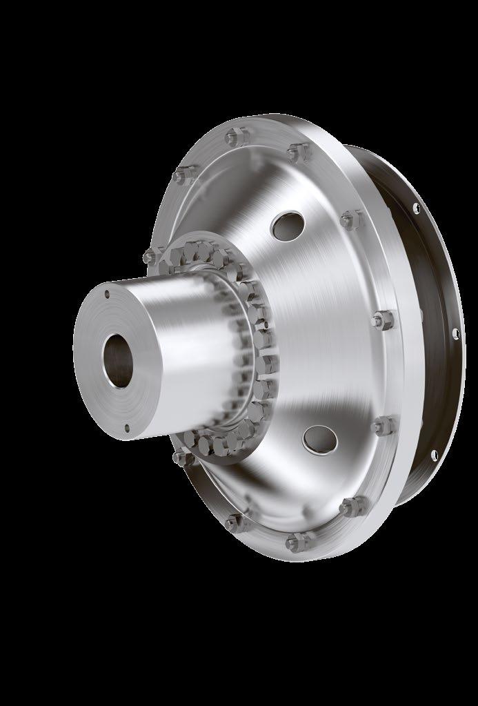
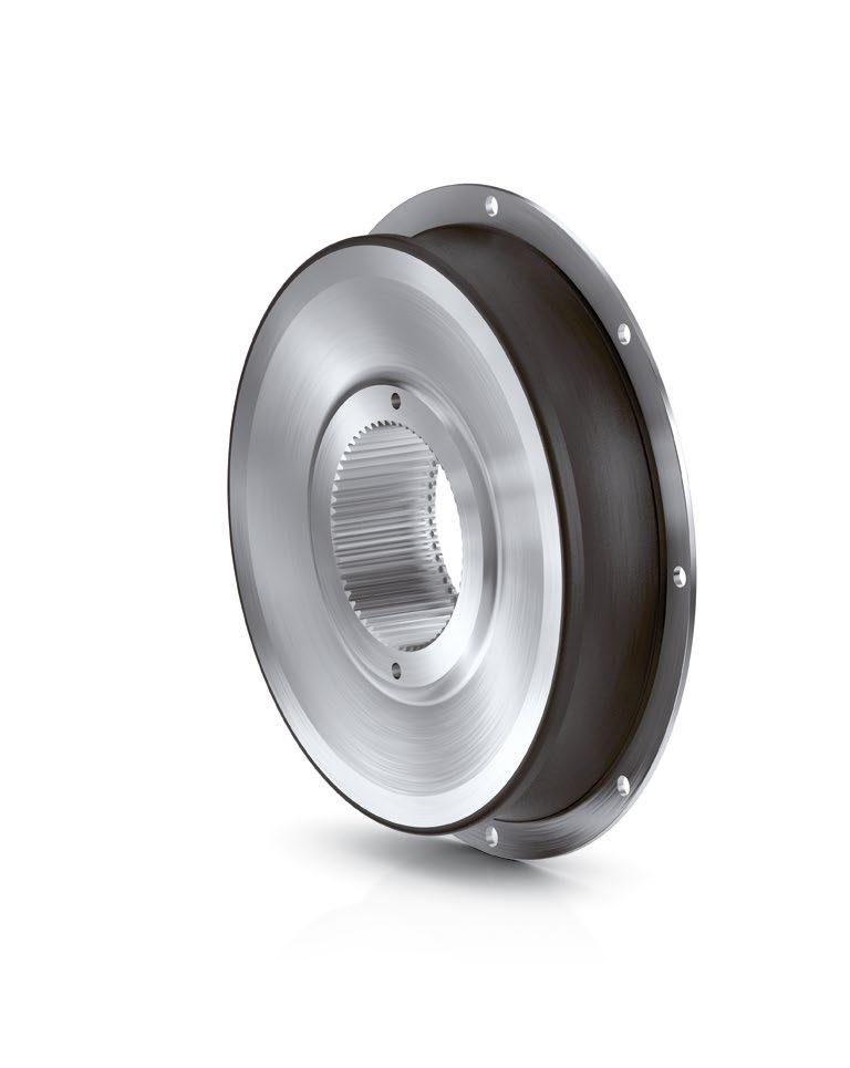
5 EIGENSCHAFTEN CHARACTERISTICS DREHMOMENT TORQUE RANGE KNM HOCHELASTISCHE KUPPLUNGEN Die Kupplung ist eine hochelastische Elastomerkupplung für Antriebe im Drehmomentbereich TKN 0,21 26,00 knm. HIGHLY FLEXIBLE COUPLINGS The coupling is a highly flexible elastomer coupling for drives with a torque range of TKN knm. Zur drehschwingungsstechnischen Abstimmung auf die entsprechenden Anlagen anforderungen stehen in der Gummivariante der Kupplung mit linearer Drehfederkennlinie vier Elementsteifigkeiten zur Verfügung. Alternativ sind Elemente in Silikon mit einer progressiven Drehfederkennlinie lieferbar. Die Gummi- Elemente können bei Umgebungstemperaturen von -45 C bis +90 C eingesetzt werden. Für temperatur- kritischere Anwendungen wird der Einsatz der Silikonvariante empfohlen; hier liegt der zulässige Temperaturbereich bei -45 C bis +120 C. Bei Glockeneinbauten sollte im Interesse einer hohen Lebensdauer der Kupplung auf ausreichende Belüftungsquerschnitte geachtet werden. For optimum configuration with the relevant system requirements in terms of torsional vibration, four rubber qualities with linear torsional spring characteristics are available. As an alternative, elements are available in silicone with progressive torsional spring characteristics. The natural rubber elements can be used at ambient temperatures from -45 C to +90 C. For temperature-critical applications, the use of the silicone variant is recommended; here the admissible temperature range is -45 C to +120 C. For bell housing installations, in the interest of maintaining a long service life of the coupling, it should be ensured that there are sufficient ventilation cross-sections. Die hochelastische Kupplung sorgt für eine spielfreie Drehmomentübertragung, sie dämpft effizient Drehschwingungen und Stöße und gleicht radiale, axiale und winkelige Verlagerungen aus. Aufgrund der Vermeidung von Körperschallbrücken (direkter Metallkontakt) bietet die Kupplung ausgezeichnete Geräuschdämmungseigenschaften. The highly flexible coupling ensures a torque transmission free of backlash, it efficiently damps torsional vibrations and shocks, and compensates radial, axial and angular misalignments. Due to the prevention of structureborne noise bridges (direct metal contact) the coupling provides excellent sound insulation properties. Bei der steckbaren Ausführung der Kupplung sorgt die innere Keilverzahnung für eine hohe Montagefreundlichkeit in Glockeneinbauten. In the pluggable version of the coupling, the inner spline ensures ease of installation in bell housing applications. Die hochelastische Kupplung in freistehender Ausführung findet Verwendung in Hauptantrieben mit elastisch aufgestellten Motoren wie auch in Generator- und Pumpenantrieben. Sie ergänzt die RATO Kupplung im unteren Drehmomentbereich. The free standing design of the highly flexible coupling is used in main drives with flexibly mounted engine installations, as well as in generator and pump drives. It complements the RATO coupling in the lower torque range. Für die Schwungradanschlüsse ist die SAE J620 Norm zugrunde gelegt. Die ist auch als Welle-Welle-Kupplung erhältlich. The SAE J620 standard is used as the basis for flywheel connections. The is also available as a shaft-shaft coupling. VULKAN COUPLINGS 05
6 BAUREIHENÜBERSICHT SUMMARY OF SERIES 4000 BAUREIHE KKE401FC00SERIES Seite 12 Page BAUREIHE SERIES KKE491GD01 Seite 14 Page 14 Zur Verbindung eines SAE-Schwungrades J620 mit einer Welle. For connecting an SAE flywheel J620 to a shaft. Zur Verbindung eines SAE-Schwungrades J620 mit einer Welle. For connecting an SAE flywheel J620 to a shaft. Ausführung für Glockeneinbauten. Elementenwechsel durch Verschieben der verbundenen Maschinen. Execution for bell housing installations. Replacement of elements by moving the adjacent machinery. Ausführung für Glockeneinbauten. Elementenwechsel durch Verschieben der verbundenen Maschinen. Mit Durchdrehsicherung. Execution for bell housing installations. Replacement of elements by moving the adjacent machinery. With torsional limit device. Baugruppe Dimension Group K 1710 K 2810 Nenndrehmoment Nominal Torque 0,21 1,63 knm Baugruppe Dimension Group K 2810 K 4910 Nenndrehmoment Nominal Torque 1,30 6,50 knm 4110 KKE571IF00 BAUREIHE SERIES Seite 16 Page KKE541JF00 BAUREIHE SERIES Seite 18 Page 18 Zur Verbindung eines Schwungrades mit einer Welle bei hohen Drehmomenten. For connecting a flywheel with a shaft at high torques. Zur Verbindung eines Schwungrades mit einer Welle bei hohen Drehmomenten. For connecting a flywheel with a shaft at high torques. Elementenwechsel ohne Verschieben der verbundenen Maschinen. Nach Entfernung des Adapterrings kann das Element senkrecht ausgebaut werden. Replacement of elements without moving the adjacent machinery. After displacement of the adapter ring, the element can be removed vertically. Elementenwechsel ohne Verschieben der verbundenen Maschinen. Nach Entfernung des Adapterrings kann das Element senkrecht ausgebaut werden. Mit Durchdrehsicherung. Replacement of elements without moving the adjacent machinery. After displacement of the adapter ring, the element can be removed vertically. With torsional limit device. Baugruppe Dimension Group K 4010 K 6010 Nenndrehmoment Nominal Torque 3,25 26,00 Baugruppe Dimension Group K 4010 K 6010 Nenndrehmoment Nominal Torque 3,25 26,00 06 VULKAN COUPLINGS
7 4400 KKE541K000 BAUREIHE SERIES Seite 20 Page 20 Zur Verbindung zweier Wellen. For the connection of two shafts. Elementenwechsel ohne Verschieben der verbundenen Maschinen. Durch Zurückziehen des Flanschmantels können die Elemente senkrecht ausgebaut werden. Replacement of elements without moving the adjacent machinery. The elements can be removed vertically by moving the flanged casing. Baugruppe Dimension Group K 4110 K 6010 Nenndrehmoment Nominal Torque 3,25 26,00 VULKAN COUPLINGS 07
8 GEGLOCKTE ANWENDUNG AUSFÜHRUNG: GUMMI BELL HOUSING APPLICATION EXECUTION: RUBBER LEISTUNGSDATEN PERFORMANCE DATA Kupplungstyp Type of Coupling T KN L 3) M 3) C 3) T Kmax1 T Kmax2 ΔT max T KW P KV50;1h n Kmax ΔK r 2) C rdyn 1) C Tdyn 1) 2) 1) 2) ψ [knm] S L S M S C [knm] [knm] [knm] [knm] [kw] [1/min] [mm] [kn/mm] [knm/rad] nominal nominal Größe Baugruppe Nenndrehmoment Anwendungsfaktor Max. Max. Drehmoment Wechseldrehmoment Drehmoment 1 Drehmoment 2 Bereich Verlustleistung Drehzahl Radialer Kupplungsversatz Radiale Federsteife Dynamische Drehfedersteife Verhältnismäßige Dämpfung Size Dimension Group Nominal Torque Duty-Class Factor Max. Torque 1 Max. Torque 2 Torque Range Vibratory Torque Power Loss Rotational Speed Radial Coupling Displacement Radial Stiffness Dynamic Torsional Stiffness Relative Damping K 1714 K ,21 1,00 0,89 0,77 0,24 0,58 0,17 0,06 0, ,6 0,15 0,65 0,75 K 1711 K ,21 1,00 0,89 0,77 0,24 0,58 0,26 0,06 0, ,6 0,19 0,85 1,00 K 1715 K ,26 1,00 0,89 0,77 0,30 0,72 0,34 0,06 0, ,1 0,33 1,45 1,13 K 1712 K ,26 1,00 0,89 0,77 0,30 0,72 0,42 0,06 0, ,5 0,45 2,00 1,13 K 2314 K ,72 1,00 0,89 0,77 0,83 1,98 0,54 0,22 0, ,7 0,40 1,75 0,75 K 2311 K ,72 1,00 0,89 0,77 0,83 1,98 0,82 0,22 0, ,7 0,52 2,30 1,00 K 2315 K ,88 1,00 0,89 0,77 1,02 2,45 1,09 0,22 0, ,4 1,02 4,50 1,13 K 2312 K ,88 1,00 0,89 0,77 1,02 2,45 1,35 0,22 0, ,0 1,41 6,20 1,13 K 2414 K ,82 1,00 0,89 0,77 0,95 2,27 0,62 0,25 0, ,0 0,56 2,60 0,75 K 2411 K ,82 1,00 0,89 0,77 0,95 2,27 0,94 0,25 0, ,0 0,75 3,50 1,00 K 2415 K ,04 1,00 0,89 0,77 1,20 2,88 1,25 0,25 0, ,2 1,29 6,00 1,13 K 2412 K ,04 1,00 0,89 0,77 1,20 2,88 1,55 0,25 0, ,8 1,79 8,30 1,13 K 2814 K ,30 1,00 0,89 0,77 1,50 3,60 0,98 0,40 0, ,4 0,64 4,10 0,75 K 2811 K ,30 1,00 0,89 0,77 1,50 3,60 1,49 0,40 0, ,4 0,86 5,50 1,00 K 2815 K ,63 1,00 0,89 0,77 1,88 4,50 1,97 0,40 0, ,4 1,47 9,40 1,13 K 2812 K ,63 1,00 0,89 0,77 1,88 4,50 2,45 0,40 0, ,0 2,04 13,00 1,13 K 3214 K ,63 1,00 0,89 0,77 1,88 4,50 1,14 0,50 0, ,2 0,57 4,20 0,75 K 3211 K ,63 1,00 0,89 0,77 1,88 4,50 1,74 0,50 0, ,2 0,74 5,50 1,00 K 3215 K ,95 1,00 0,89 0,77 2,25 5,40 2,30 0,50 0, ,6 1,52 11,30 1,13 K 3212 K ,95 1,00 0,89 0,77 2,25 5,40 2,86 0,50 0, ,1 2,1 15,60 1,13 K 3414 K ,08 1,00 0,89 0,77 2,40 5,76 1,58 0,64 0, ,4 0,51 5,40 0,75 K 3411 K ,08 1,00 0,89 0,77 2,40 5,76 2,41 0,64 0, ,4 0,70 7,50 1,00 K 3415 K ,60 1,00 0,89 0,77 3,00 7,20 3,19 0,64 0, ,2 1,34 14,70 1,13 K 3412 K ,60 1,00 0,89 0,77 3,00 7,20 3,96 0,64 0, ,6 1,85 20,50 1,13 K 4014 K ,25 1,00 0,89 0,77 3,75 9,00 2,45 1,00 0, ,9 0,51 8,00 0,75 K 4011 K ,25 1,00 0,89 0,77 3,75 9,00 3,72 1,00 0, ,9 0,70 11,00 1,00 K 4015 K ,10 1,00 0,89 0,77 4,73 11,34 4,93 1,00 0, ,1 1,34 21,00 1,13 K 4012 K ,10 1,00 0,89 0,77 4,73 11,34 6,12 1,00 0, ,3 1,85 29,00 1,13 K 4914 K ,20 1,00 0,89 0,77 6,00 14,40 4,31 1,60 0, ,2 0,52 16,50 0,75 K 4911 K ,20 1,00 0,89 0,77 6,00 14,40 6,55 1,60 0, ,2 0,69 22,00 1,00 K 4915 K ,50 1,00 0,89 0,77 7,50 18,00 8,68 1,60 0, ,8 1,18 37,50 1,13 K 4912 K ,50 1,00 0,89 0,77 7,50 18,00 10,79 1,60 0, ,5 1,64 52,00 1,13 Siehe Erläuterung der Technischen Daten 1) VULKAN empfiehlt die zusätzliche Berücksichtigung von C Tdyn warm (0,7), C Tdyn la (1,35) und ψ warm (0,7) für die Berechnung der Drehschwingungen in der Anlage. 2) Der Betriebszustand der Anlage kann eine Korrektur der gegebenen Werte notwendig machen. Siehe Erläuterungen der Technischen Daten. Bei mehrreihigen Kupplungen müssen bei der Drehschwingungsanalyse der Anlage die individuellen Massenträgheitsmomente der Kupplung und die dynamischen Drehfedersteifen der einzelnen Elemente berücksichtigt werden. Durch die Eigenschaft des Werkstoffs Gummi sind Toleranzen der aufgeführten Daten für C Tdyn von + 30 % bis 0 % für die 4er Elemente bzw. von +10 % bis - 20 % für die 1er und Silikon-Elemente bzw. von + 20 % bis - 10 % für die 5/2er Elemente möglich. Für ψ sind Toleranzen von 10 % bis -20% möglich. 3) Bitte beachten Sie unsere Auslegungsbeispiele ab Seite 22. See Explanation of the Technical Data 1) VULKAN recommends additionally taking into account C Tdyn warm (0,7), C Tdyn la (1,35) and ψ warm (0,7) for calculating the torsional vibration in the system. 2) The operating state of the system can make it necessary to correct the values given. See Technical Data notes. With multi-row couplings, the individual moments of inertia of the coupling and the dynamic torsional stiffnesses of the individual elements must be taken into account during the torsional vibration analysis of the system. The properties of the rubber mean that tolerances of + 30 % to 0 % for the 4 elements and + 10 % to - 20 % for the 1 and silicone elements, and + 20 % to -10 % for the 5/2 elements with respect to the data given for C Tdyn are possible. For ψ tolerances are possible from 10 % to -20%. 3) Please consider our sample selection on page 22 ff. 08 VULKAN COUPLINGS
9 FREISTEHENDE ANWENDUNG AUSFÜHRUNG: GUMMI FREE STANDING APPLICATION EXECUTION: RUBBER LEISTUNGSDATEN PERFORMANCE DATA Kupplungstyp Type of Coupling T KN L 3) M 3) C 3) T Kmax1 T Kmax2 ΔT max T KW P KV50;1h n Kmax ΔK r 2) ΔK a C rdyn 1) C Tdyn 1) 2) 1) 2) ψ [knm] S L S M S C [knm] [knm] [knm] [knm] [kw] [1/min] [mm] [mm] [kn/mm] [knm/rad] nominal nominal Größe Baugruppe Nenndrehmoment Anwendungsfaktor Max. Drehmoment 1 Duty-Class Factor Max. Torque 1 Max. Drehmoment 2 Max. Torque 2 Drehmoment Bereich Torque Range Wechseldrehmoment Vibratory Torque Verlustleistung Drehzahl Radialer Kupplungsversatz Radial Coupling Displacement Radiale Federsteife Dynamische Drehfedersteife Axialer Kupplungsversatz Axial Coupling Displacement Verhältnismäßige Dämpfung Relative Damping Size Dimension Group Nominal Torque Power Loss Rotational Speed Radial Stiffness Dynamic Torsional Stiffness K 4014 K ,25 1,00 0,89 0,77 3,75 9,00 2,45 1,00 0, ,9 3,5 0,51 8,00 0,75 K 4011 K ,25 1,00 0,89 0,77 3,75 9,00 3,72 1,00 0, ,9 3,5 0,70 11,00 1,00 K 4015 K ,10 1,00 0,89 0,77 4,73 11,34 4,93 1,00 0, ,1 3,5 1,34 21,00 1,13 K 4012 K ,10 1,00 0,89 0,77 4,73 11,34 6,12 1,00 0, ,3 3,5 1,85 29,00 1,13 K 4114 K ,25 1,00 0,89 0,77 3,75 9,00 3,50 1,00 0, ,9 3,5 0,50 10,00 0,75 K 4111 K ,25 1,00 0,89 0,77 3,75 9,00 3,95 1,00 0, ,3 3,5 0,60 13,50 1,00 K 4115 K ,03 1,00 0,89 0,77 4,65 11,16 5,40 1,00 0, ,4 3,5 1,10 23,00 1,13 K 4112 K ,03 1,00 0,89 0,77 4,65 11,16 6,10 1,00 0, ,1 3,5 1,50 32,00 1,13 K 4814 K ,20 1,00 0,89 0,77 6,00 14,40 5,69 1,60 0, ,7 3,5 0,67 16,50 0,75 K 4811 K ,20 1,00 0,89 0,77 6,00 14,40 6,39 1,60 0, ,3 3,5 0,89 22,00 1,00 K 4815 K ,50 1,00 0,89 0,77 7,50 18,00 8,75 1,60 0, ,3 3,5 1,51 37,50 1,13 K 4812 K ,50 1,00 0,89 0,77 7,50 18,00 9,91 1,60 0, ,1 3,5 2,10 52,00 1,13 K 4914 K ,20 1,00 0,89 0,77 6,00 14,40 4,31 1,60 0, ,2 3,5 0,52 16,50 0,75 K 4911 K ,20 1,00 0,89 0,77 6,00 14,40 6,55 1,60 0, ,2 3,5 0,69 22,00 1,00 K 4915 K ,50 1,00 0,89 0,77 7,50 18,00 8,68 1,60 0, ,8 3,5 1,18 37,50 1,13 K 4912 K ,50 1,00 0,89 0,77 7,50 18,00 10,79 1,60 0, ,5 3,5 1,64 52,00 1,13 K 5414 K ,19 1,00 0,89 0,77 9,45 22,68 5,99 2,50 0, ,7 4,0/4,5* 0,53 22,00 0,75 K 5411 K ,19 1,00 0,89 0,77 9,45 22,68 9,01 2,50 0, ,7 4,0/4,5* 0,72 29,50 1,00 K 5415 K ,40 1,00 0,89 0,77 12,00 28,80 11,93 2,50 0, ,3 4,0/4,5* 1,46 60,00 1,13 K 5412 K ,40 1,00 0,89 0,77 12,00 28,80 14,83 2,50 0, ,8 4,0/4,5* 2,02 83,00 1,13 K 5714 K ,00 1,00 0,89 0,77 15,00 36,00 9,44 4,00 0, ,4 4,5 0,75 34,50 0,75 K 5711 K ,00 1,00 0,89 0,77 15,00 36,00 14,35 4,00 0, ,4 4,5 1,00 46,00 1,00 K 5715 K ,25 1,00 0,89 0,77 18,75 45,00 19,00 4,00 0, ,2 4,5 2,02 93,00 1,13 K 5712 K ,25 1,00 0,89 0,77 18,75 45,00 23,62 4,00 0, ,7 4,5 2,78 128,00 1,13 K 6014 K ,80 1,00 0,89 0,77 24,00 57,50 14,96 6,40 0, ,6 6,0 1,08 62,00 0,75 K 6011 K ,80 1,00 0,89 0,77 24,00 57,50 22,72 6,40 0, ,6 6,0 1,48 85,00 1,00 K 6015 K ,00 1,00 0,89 0,77 30,00 72,00 30,10 6,40 0, ,9 6,0 2,59 149,00 1,13 K 6012 K ,00 1,00 0,89 0,77 30,00 72,00 37,40 6,40 0, ,6 6,0 3,58 206,00 1,13 * Gilt für Baureihe 4400 Valid for Series 4400 Siehe Erläuterung der Technischen Daten 1) VULKAN empfiehlt die zusätzliche Berücksichtigung von C Tdyn warm (0,7), C Tdyn la (1,35) und ψ warm (0,7) für die Berechnung der Drehschwingungen in der Anlage. 2) Der Betriebszustand der Anlage kann eine Korrektur der gegebenen Werte notwendig machen. Siehe Erläuterungen der Technischen Daten. Bei mehrreihigen Kupplungen müssen bei der Drehschwingungsanalyse der Anlage die individuellen Massenträgheitsmomente der Kupplung und die dynamischen Drehfedersteifen der einzelnen Elemente berücksichtigt werden. Durch die Eigenschaft des Werkstoffs Gummi sind Toleranzen der aufgeführten Daten für C Tdyn von + 30 % bis 0 % für die 4er Elemente bzw. von +10 % bis - 20 % für die 1er und Silikon-Elemente bzw. von + 20 % bis - 10 % für die 5/2er Elemente möglich. Für ψ sind Toleranzen von 10 % bis -20% möglich. 3) Bitte beachten Sie unsere Auslegungsbeispiele ab Seite 22. See Explanation of the Technical Data 1) VULKAN recommends additionally taking into account C Tdyn warm (0,7), C Tdyn la (1,35) and ψ warm (0,7) for calculating the torsional vibration in the system. 2) The operating state of the system can make it necessary to correct the values given. See Technical Data notes. With multi-row couplings, the individual moments of inertia of the coupling and the dynamic torsional stiffnesses of the individual elements must be taken into account during the torsional vibration analysis of the system. The properties of the rubber mean that tolerances of + 30 % to 0 % for the 4 elements and + 10 % to - 20 % for the 1 and silicone elements, and + 20 % to -10 % for the 5/2 elements with respect to the data given for C Tdyn are possible. For ψ tolerances are possible from 10 % to -20%. 3) Please consider our sample selection on page 22 ff. VULKAN COUPLINGS 09
10 GEGLOCKTE ANWENDUNG AUSFÜHRUNG: SILIKON BELL HOUSING APPLICATION EXECUTION: SILICONE LEISTUNGSDATEN PERFORMANCE DATA Kupplungstyp Type of Coupling T KN L 3) M 3) C 3) T Kmax1 T Kmax2 ΔT max T KW P KV50;1h n Kmax ΔK r 2) C rdyn 1) C Tdyn 1) 2) 1) 2) ψ [knm] S L S M S C [knm] [knm] [knm] [knm] [kw] [1/min] [mm] [kn/ mm] [knm/rad] nominal nominal 10 % T kn 25 % T kn 50 % T kn 75 % T kn 100 % T kn Size Dimension Group Nominal Torque Größe Baugruppe Nenndrehmoment Anwendung Anwendungsfaktor Max. Drehmoment 1 Duty Duty-Class Factor Max. Torque 1 Max. Drehmoment 2 Max. Torque 2 Drehmoment Bereich Torque Range Wechseldrehmoment Vibratory Torque Verlustleistung Power Loss Drehzahl Rotational Speed Radialer Kupplungsversatz Radial Coupling Displacement Radial Stiffness Dynamische Drehfedersteife Dynamic Torsional Stiffness Radiale Federsteife Verhältnismäßige Dämpfung Relative Damping K 2811 K ,63 L 1,00 1,75 2,50 1,54 0,40 0, ,9 1,10 4,4 4,5 5,8 10,1 18,8 1,13 K 2811 K ,63 M 0,77 1,75 2,50 1,54 0,40 0, ,9 1,10 4,4 4,6 4,7 7,0 10,5 1,13 K 2811 K ,63 C 0,62 1,75 2,50 1,54 0,40 0, ,9 1,10 4,4 4,4 4,6 5,5 7,4 1,13 K 3411 K ,60 L 1,00 2,80 4,00 2,50 0,64 0, ,8 1,12 6,9 7,1 10,1 17,1 28,9 1,13 K 3411 K ,60 M 0,77 2,80 4,00 2,50 0,64 0, ,8 1,12 6,9 7,0 8,1 11,8 17,6 1,13 K 3411 K ,60 C 0,62 2,80 4,00 2,50 0,64 0, ,8 1,12 6,9 6,9 7,5 9,4 12,8 1,13 K 4011 K ,10 L 1,00 4,41 6,30 3,86 1,00 0, ,3 1,27 10,2 11,3 17,1 29,5 46,7 1,13 K 4011 K ,10 M 0,77 4,41 6,30 3,86 1,00 0, ,3 1,27 10,0 11,0 13,2 20,0 32,0 1,13 K 4011 K ,10 C 0,62 4,41 6,30 3,86 1,00 0, ,3 1,27 9,9 10,1 11,6 15,7 22,2 1,13 K 4911 K ,50 L 1,00 7,00 10,00 6,80 1,60 0, ,3 1,07 19,5 20,9 28,1 46,4 81,9 1,13 K 4911 K ,50 M 0,77 7,00 10,00 6,80 1,60 0, ,3 1,07 19,4 19,9 23,1 33,9 47,0 1,13 K 4911 K ,50 C 0,62 7,00 10,00 6,80 1,60 0, ,3 1,07 19,0 19,8 21,9 26,4 34,8 1,13 Siehe Erläuterung der Technischen Daten 1) VULKAN empfiehlt die zusätzliche Berücksichtigung von C Tdyn warm (0,7), C Tdyn la (1,35) und ψ warm (0,7) für die Berechnung der Drehschwingungen in der Anlage. 2) Der Betriebszustand der Anlage kann eine Korrektur der gegebenen Werte notwendig machen. Siehe Erläuterungen der Technischen Daten. Bei mehrreihigen Kupplungen müssen bei der Drehschwingungsanalyse der Anlage die individuellen Massenträgheitsmomente der Kupplung und die dynamischen Drehfedersteifen der einzelnen Elemente berücksichtigt werden. Durch die Eigenschaft des Werkstoffs Gummi sind Toleranzen der aufgeführten Daten für C Tdyn von + 30 % bis 0 % für die 4er Elemente bzw. von +10 % bis - 20 % für die 1er und Silikon-Elemente bzw. von + 20 % bis - 10 % für die 5/2er Elemente möglich. Für ψ sind Toleranzen von 10 % bis -20% möglich. 3) Bitte beachten Sie unsere Auslegungsbeispiele ab Seite 22. See Explanation of the Technical Data 1) VULKAN recommends additionally taking into account C Tdyn warm (0,7), C Tdyn la (1,35) and ψ warm (0,7) for calculating the torsional vibration in the system. 2) The operating state of the system can make it necessary to correct the values given. See Technical Data notes. With multi-row couplings, the individual moments of inertia of the coupling and the dynamic torsional stiffnesses of the individual elements must be taken into account during the torsional vibration analysis of the system. The properties of the rubber mean that tolerances of + 30 % to 0 % for the 4 elements and + 10 % to - 20 % for the 1 and silicone elements, and + 20 % to -10 % for the 5/2 elements with respect to the data given for C Tdyn are possible. For ψ tolerances are possible from 10 % to -20%. 3) Please consider our sample selection on page 22 ff. 10 VULKAN COUPLINGS
11 FREISTEHENDE ANWENDUNG AUSFÜHRUNG: SILIKON FREE STANDING APPLICATION EXECUTION: SILICONE LEISTUNGSDATEN PERFORMANCE DATA Kupplungstyp Type of Coupling T KN L 3) M 3) C 3) T Kmax1 T Kmax2 ΔT max T KW P KV50;1h n Kmax ΔK r 2) ΔK a C rdyn 1) C Tdyn 1) 2) 1) 2) ψ [knm] S L S M S C [knm] [knm] [knm] [knm] [kw] [1/min] [mm] [mm] [kn/ mm] [knm/rad] nominal nominal 10 % T kn 25 % T kn 50 % T kn 75 % T kn 100 % T kn Size Dimension Group Nominal Torque Größe Baugruppe Nenndrehmoment Anwendung Anwendungsfaktor Max. Drehmoment 1 Duty Duty-Class Factor Max. Torque 1 Max. Drehmoment 2 Max. Torque 2 Torque Range Vibratory Torque Drehmoment Bereich Wechseldrehmoment Verlustleistung Power Loss Drehzahl Verhältnismäßige Dämpfung Relative Damping Rotational Speed Radialer Kupplungsversatz Radial Coupling Displacement Axialer Kupplungsversatz Axial Coupling Displacement Radial Stiffness Dynamische Drehfedersteife Dynamic Torsional Stiffness Radiale Federsteife K 4011 K ,10 L 1,00 4,41 6,30 3,86 1,00 0, ,3 3,5 1,27 10,2 11,3 17,1 29,5 46,7 1,13 K 4011 K ,10 M 0,77 4,41 6,30 3,86 1,00 0, ,3 3,5 1,27 10,0 11,0 13,2 20,0 32,0 1,13 K 4011 K ,10 C 0,62 4,41 6,30 3,86 1,00 0, ,3 3,5 1,27 9,9 10,1 11,6 15,7 22,2 1,13 K 4911 K ,50 L 1,00 7,00 10,00 6,80 1,60 0, ,3 3,5 1,07 19,5 20,9 28,1 46,4 81,9 1,13 K 4911 K ,50 M 0,77 7,00 10,00 6,80 1,60 0, ,3 3,5 1,07 19,4 19,9 23,1 33,9 47,0 1,13 K 4911 K ,50 C 0,62 7,00 10,00 6,80 1,60 0, ,3 3,5 1,07 19,0 19,8 21,9 26,4 34,8 1,13 K 5411 K ,40 L 1,00 11,20 16,00 9,35 2,50 0, ,9 4,0/4,5* 1,30 31,5 36,0 45,2 72,5 115,5 1,13 K 5411 K ,40 M 0,77 11,20 16,00 9,35 2,50 0, ,9 4,0/4,5* 1,30 30,9 35,4 42,8 53,6 65,5 1,13 K 5411 K ,40 C 0,62 11,20 16,00 9,35 2,50 0, ,9 4,0/4,5* 1,30 30,0 33,2 34,8 42,4 55,8 1,13 K 5711 K ,25 L 1,00 17,50 25,00 14,89 4,00 0, ,7 4,5 1,82 48,5 56,0 71,5 119,9 204,0 1,13 K 5711 K ,25 M 0,77 17,50 25,00 14,89 4,00 0, ,7 4,5 1,82 48,2 55,2 66,8 83,7 102,2 1,13 K 5711 K ,25 C 0,62 17,50 25,00 14,89 4,00 0, ,7 4,5 1,82 48,0 49,8 55,0 63,5 88,2 1,13 K 6011 K ,00 L 1,00 28,00 40,00 23,59 6,40 1, ,9 6,0 1,46 71,0 76,5 105,8 227,3 428,0 1,13 K 6011 K ,00 M 0,77 28,00 40,00 23,59 6,40 1, ,9 6,0 1,46 70,0 75,9 93,6 150,9 251,0 1,13 K 6011 K ,00 C 0,62 28,00 40,00 23,59 6,40 1, ,9 6,0 1,46 64,0 65,0 68,5 94,1 152,0 1,13 * Gilt für Baureihe 4400 Valid for Series 4400 Siehe Erläuterung der Technischen Daten 1) VULKAN empfiehlt die zusätzliche Berücksichtigung von C Tdyn warm (0,7), C Tdyn la (1,35) und ψ warm (0,7) für die Berechnung der Drehschwingungen in der Anlage. 2) Der Betriebszustand der Anlage kann eine Korrektur der gegebenen Werte notwendig machen. Siehe Erläuterungen der Technischen Daten. Bei mehrreihigen Kupplungen müssen bei der Drehschwingungsanalyse der Anlage die individuellen Massenträgheitsmomente der Kupplung und die dynamischen Drehfedersteifen der einzelnen Elemente berücksichtigt werden. Durch die Eigenschaft des Werkstoffs Gummi sind Toleranzen der aufgeführten Daten für C Tdyn von + 30 % bis 0 % für die 4er Elemente bzw. von +10 % bis - 20 % für die 1er und Silikon-Elemente bzw. von + 20 % bis - 10 % für die 5/2er Elemente möglich. Für ψ sind Toleranzen von 10 % bis -20% möglich. 3) Bitte beachten Sie unsere Auslegungsbeispiele ab Seite 22. See Explanation of the Technical Data 1) VULKAN recommends additionally taking into account C Tdyn warm (0,7), C Tdyn la (1,35) and ψ warm (0,7) for calculating the torsional vibration in the system. 2) The operating state of the system can make it necessary to correct the values given. See Technical Data notes. With multi-row couplings, the individual moments of inertia of the coupling and the dynamic torsional stiffnesses of the individual elements must be taken into account during the torsional vibration analysis of the system. The properties of the rubber mean that tolerances of + 30 % to 0 % for the 4 elements and + 10 % to - 20 % for the 1 and silicone elements, and + 20 % to -10 % for the 5/2 elements with respect to the data given for C Tdyn are possible. For ψ tolerances are possible from 10 % to -20%. 3) Please consider our sample selection on page 22 ff. VULKAN COUPLINGS 11
12 BAUREIHE SERIES 4000 A L5 L1 L11 L7 Ø D1 Ø D16 Ø D3 min. Ø D3 max. L2 Ø D11 Ø D15 T1 Ø D M2 M1 S2 S1 GEOMETRISCHE DATEN GEOMETRIC DATA Baugruppe Schwungrad Abbildung Abmessungen Dimension Group Flywheel Figure Dimension SAEJ620 D 1 D 3 D 11 D 14 D 15 T 1 D 16 L 1 L 2 L 5 L 7 L 11 [ ] [mm] [mm] [mm] [mm] [mm] [-] [mm] [mm] [mm] [mm] [mm] [mm] Teilung / holes K ,0 35,0 50,0 240,8 222,3 6,0 9,0 27,6 31,0 29,2 4,2 10,2 K ½ A 182,0 43,0 55,0 216,0 200,0 12 9,0 36,5 25,0 40,0 3,0 2,7 K 2310 A 182,0 43,0 55,0 311,2 288,8 3x2 11,5 39,5 25,0 43,0 3,0 3,6 K ½ A 182,0 43,0 55,0 352,4 333,4 8 11,0 26,5 25,0 30,0 3,0 12,7 K 2410 A 190,0 43,0 55,0 225,0 210,0 12 6,2 43,5 44,0 34,5 3,0 3,0 K A 190,0 43,0 55,0 314,4 295,3 8 11,0 46,5 44,0 46,5 3,0 5,5 K ½ A 190,0 43,0 55,0 352,4 333,4 8 11,0 24,5 33,5 24,5 3,0 13,0 K A 222,0 50,0 65,0 263,5 244,5 12 8,2 38,0 38,0 41,0 4,0 3,0 K ½ A 222,0 50,0 65,0 352,4 333,4 8 11,0 33,0 44,0 30,0 3,0 22,0 12 VULKAN COUPLINGS
13 Massenträgheitsmomente Masse Schwerpunktsabstand Anmerkungen Mass moments of inertia Mass Distance to center of gravity Notes J 1 J 2 M 1 M 2 S 1 S 2 [kgm²] [kgm²] [kg] [kg] [mm] [mm] 0,006 0,002 1,3 1,1 2,1 8,4 0,010 0,010 1,1 1,7 0,040 0,010 2,8 1,7 0,040 0,010 3,1 1,7 3,4 5,4 0,010 0,010 1,1 2,1 3,6 18,3 0,030 0,010 2,5 2,1 4,3 18,3 0,040 0,010 2,7 1,9 0,030 0,020 2,2 3,2 0,070 0,040 6,8 5,6 2,7 15,9 VULKAN COUPLINGS 13
14 BAUREIHE SERIES 4001 mit Durchdrehsicherung* with torsional limit device* A L5 L1 L7 L11 Ø D15 T1 Ø D Ø D1 Ø D3 min. Ø D3 max. Ø D11 Ø D16 L2 M2 M1 S2 S1 GEOMETRISCHE DATEN GEOMETRIC DATA Baugruppe Schwungrad Abbildung Abmessungen Dimension Group Flywheel Figure Dimension SAEJ620 D 1 D 3 D 11 D 14 D 15 T 1 D 16 L 1 L 2 L 5 L 7 L 11 [ ] [mm] [mm] [mm] [mm] [mm] [-] [mm] [mm] [mm] [mm] [mm] [mm] Teilung / holes K A 222,0 50,0 65,0 263,5 244,5 12 8,2 38,0 38,0 41,0 4,0 3,0 K ½ A 222,0 50,0 65,0 352,4 333,4 8 11,0 33,0 44,0 30,0 3,0 22,0 K 3210 A 58,0 75,0 280,0 260,0 12 8,2 74,0 70,0 47,0 4,0 2,8 K ½ A 234,0 58,0 75,0 352,4 333,4 8 11,0 81,0 83,0 54,0 4,0 2,0 K A 234,0 58,0 75,0 466,7 438,2 8 14,0 60,0 62,0 43,0 5,0 2,0 K ½ A 266,0 84,0 110,0 352,4 333,4 8 11,0 45,0 53,0 47,0 4,0 10,8 K ½ A 312,0 120,0 157,0 352,4 333,4 8 11,0 64,0 66,0 66,0 4,0 2,8 K A 312,0 120,0 157,0 466,7 438,2 8 14,0 50,0 66,0 52,0 4,0 16,7 K A 407,0 200,0 265,0 466,7 438,2 8 14,0 69,0 77,0 76,0 6,0 4,7 K A 407,0 200,0 265,0 571,5 542, ,0 59,5 77,0 66,5 6,0 14,2 14 VULKAN COUPLINGS
15 Massenträgheitsmomente Masse Schwerpunktsabstand Anmerkungen Mass moments of inertia Mass Distance to center of gravity Notes J 1 J 2 M 1 M 2 S 1 S 2 Weitere Baugruppen mit Durchdrehsicherung möglich. [kgm²] [kgm²] [kg] [kg] [mm] [mm] * Standardelemente mit 25 % Durchdrehsicherung. Sonderelement mit 100 % Durchdrehsicherung verfügbar. Additional series with torsional limit device available. * Standard element with 25 % torsional limit device. Special element with 100 % torsional limit device available. 0,03 0,02 2,2 3,2 0,07 0,04 6,8 5,6 2,7 15,9 0,03 0,02 2,8 4,4 0,07 0,02 4,3 4,4 4,3 41,0 0,20 0,02 7,6 3,6 2,3 28,2 0,06 0,04 3,6 5,0 0,2 13,6 0,07 0,09 3,7 9,2 0,17 0,10 6,1 8,5 3,0 19,8 0,25 0,40 7,1 22,2 7,1 28,4 0,54 0,41 11,3 22,1 0,4 28,4 VULKAN COUPLINGS 15
16 BAUREIHE SERIES 4110 A B KKE401IC00 KKE601IG00 L1 L7 L11 L1 L7 Ø D1 Ø D2 Ø D3 min. Ø D3 max. Ø D16 Ø D16 F1x45~ L2 Ø D15 T1 Ø D Ø D1 Ø D2 Ø D3 min. Ø D3 max. F1x45 ~ L2 Ø D15 T1 Ø D S2 M2 M1 S1 S2 M2 M1 S1 GEOMETRISCHE DATEN GEOMETRIC DATA Baugruppe Schwungrad Abbildung Abmessungen Dimension Group Flywheel Figure Dimension SAEJ620 D 1 D 2 D 3 D 14 D 15 T 1 D 16 L 1 1) L 2 1) L 7 L 11 F 1 [ ] [mm] [mm] [mm] [mm] [mm] [mm] [-] [mm] [mm] [mm] [mm] [mm] [mm] [mm] [mm] Min. Max. Teilung / holes Min. Max. Min. Max. K ½ A 427,0 150,0 50,0 105,0 352,4 333,4 8 11,0 158,0 278,0 85,0 135,0 4,0 2,8 1,6 K A 427,0 150,0 50,0 105,0 466,7 438,2 8 14,0 144,0 264,0 85,0 135,0 4,0 16,8 1,6 K A 484,0 170,0 60,0 120,0 466,7 438,2 8 14,0 167,0 299,0 60,0 150,0 6,0 8,0 1,6 K A 484,0 170,0 60,0 120,0 571,5 542,9 6 17,0 157,5 289,5 60,0 150,0 6,0 17,5 1,6 K A 538,0 180,0 70,0 125,0 571,5 542, ,0 210,0 355,0 140,0 175,0 6,0 1,6 K A 538,0 180,0 70,0 125,0 673,1 641, ,0 210,0 355,0 140,0 175,0 6,0 1,6 K A 636,0 210,0 70,0 150,0 571,5 542, ,0 206,0 355,0 135,0 175,0 6,0 1,6 K A 636,0 210,0 70,0 150,0 673,1 641, ,0 206,0 355,0 135,0 175,0 6,0 1,6 K B 684,0 224,0 80,0 160,0 673,1 641, ,0 207,0 339,0 135,0 185,0 6,0 1,6 K B 684,0 224,0 80,0 160,0 733,4 692, ,0 207,0 339,0 135,0 185,0 6,0 1,6 16 VULKAN COUPLINGS
17 Massenträgheitsmomente Masse Schwerpunktsabstand Anmerkungen Mass moments of inertia Mass Distance to center of gravity Notes J 1 J 2 M 1 M 2 S 1 S 2 Alle Massen, Schwerpunkte und Massenträgheitsmomente beziehen sich auf min. Nabendurchmesser bei max. Nabenlänge [kgm²] [kgm²] [kg] [kg] [mm] [mm] 1) L1 und L2 beschreiben Standardsituationen und können im Anwendungsfall angepasst werden. Die Auslegung der Nabenlänge 0,07 0,63 3,6 46,5 9,2 145,7 erfolgt in Abhängigkeit des Anlagen momentes TN und muss anwendungsbezogen berechnet werden. Besuchen Sie hierfür das VULKAN Engeneering Portal auf unserer Homepage oder kontaktieren Sie die VULKAN Vertretung in ihrer Nähe. 0,17 0,63 6,1 46,5-3,1 145,7 All masses, focal points and mass moments of inertia refer to min. hub diameter at max. hub length. 0,25 1,57 6,8 83,1 7,7 172,0 1) L1 and L2 describe standard situations and can be adapted to the application. The design of the hub length is carried out 0,53 1,57 11,0 83,1 0,4 172,0 depending on the system torque TN and must be calculated use-oriented. Therefor visit the VULKAN Engineering Portal on 0,64 2,80 13,4 111,9 17,8 179,8 our homepage or contact the next VULKAN representation. 1,08 2,80 17,9 111,9 14,1 179,8 0,76 4,53 15,4 142,9 19,9 175,1 1,21 4,53 20,0 142,9 16,1 175,1 1,46 5,45 22,8 134,8 25,8 156,6 1,87 5,40 26,1 134,0 22,8 156,0 VULKAN COUPLINGS 17
18 BAUREIHE SERIES 4111 mit Durchdrehsicherung* with torsional limit device* A B KKE401JD00 KKE601JG00 L1 L7 L11 L1 L7 Ø D1 Ø D16 Ø D2 Ø D3 min. Ø D3 max. F1x45 ~ L2 Ø D15 T1 Ø D Ø D1 Ø D2 Ø D3 min. Ø D3 max. F1x45~ L2 Ø D15 T1 Ø D Ø D14 S2 M2 S1 M1 S2 M2 M1 S1 GEOMETRISCHE DATEN GEOMETRIC DATA Baugruppe Schwungrad Abbildung Abmessungen Dimension Group Flywheel Figure Dimension SAEJ620 D 1 D 2 D 3 D 14 D 15 T 1 D 16 1) L 1 1) L 2 L 7 L 11 F 1 [ ] [mm] [mm] [mm] [mm] [mm] [mm] [-] [mm] [mm] [mm] [mm] [mm] [mm] [mm] [mm] Min. Max. Teilung / holes Min. Max. Min. Max. K ½ A 427,0 150,0 50,0 105,0 352,4 333,4 8 11,0 158,0 278,0 85,0 135,0 4,0 2,8 1,6 K A 427,0 150,0 50,0 105,0 466,7 438,2 8 14,0 144,0 264,0 85,0 135,0 4,0 16,0 1,6 K A 484,0 170,0 60,0 120,0 466,7 438,2 8 14,0 167,0 299,0 60,0 150,0 6,0 8,0 1,6 K A 484,0 170,0 60,0 120,0 571,5 542,9 6 17,0 157,5 289,5 60,0 150,0 6,0 17,5 1,6 K A 538,0 180,0 70,0 125,0 571,5 542, ,0 210,0 355,0 140,0 175,0 6,0 1,6 K A 538,0 180,0 70,0 125,0 673,1 641, ,0 210,0 355,0 140,0 175,0 6,0 1,6 K A 636,0 210,0 70,0 150,0 571,5 542, ,0 206,0 355,0 135,0 175,0 6,0 1,6 K A 636,0 210,0 70,0 150,0 673,1 641, ,0 206,0 355,0 135,0 175,0 6,0 1,6 K B 684,0 224,0 80,0 160,0 673,1 641, ,0 207,0 339,0 135,0 185,0 6,0 1,6 K B 684,0 224,0 80,0 160,0 733,4 692, ,0 207,0 339,0 135,0 185,0 6,0 1,6 18 VULKAN COUPLINGS
19 Massenträgheitsmomente Masse Schwerpunktsabstand Anmerkungen Mass moments of inertia Mass Distance to center of gravity Notes J 1 J 2 M 1 M 2 S 1 S 2 Alle Massen, Schwerpunkte und Massenträgheitsmomente beziehen sich auf min. Nabendurchmesser bei max. Nabenlänge [kgm²] [kgm²] [kg] [kg] [mm] [mm] 1) L1 und L2 beschreiben Standardsituationen und können im Anwendungsfall angepasst werden. Die Auslegung der Nabenlänge 0,07 0,63 4,4 46,5 8,3 146,0 erfolgt in Abhängigkeit des Anlagen momentes TN und muss anwendungsbezogen berechnet werden. Besuchen Sie hierfür das VULKAN Engeneering Portal auf unserer Homepage oder kontaktieren Sie die VULKAN Vertretung in ihrer Nähe. 0,18 0,63 6,7 46,6-3,7 145,9 All masses, focal points and mass moments of inertia refer to min. hub diameter at max. hub length. 0,28 1,57 8,3 83,3 6,3 172,3 1) L1 and L2 describe standard situations and can be adapted to the application. The design of the hub length is carried out 0,56 1,59 12,6 83,6 0,8 172,0 depending on the system torque TN and must be calculated use-oriented. Therefor visit the VULKAN Engineering Portal on 0,71 2,79 16,8 111,7 20,9 179,5 our homepage or contact the next VULKAN representation. 1,15 2,78 21,4 111,6 17,1 179,4 0,83 4,51 18,9 142,3 22,3 175,0 1,28 4,52 23,4 142,3 18,5 175,0 1,59 5,56 28,4 139,6 28,7 159,9 1,97 5,31 31,6 136,5 22,8 159,2 VULKAN COUPLINGS 19
20 BAUREIHE SERIES 4400 A B KKE541K000 L1 L1 Ø D1 Ø D2 Ø D3 min. Ø D3 max. F1x45 ~ F2x45 ~ L2 L9 Ø D12 min. Ø D12 max. Ø D11 Ø D1 Ø D2 Ø D3 min. Ø D3 max. F1x45~ L2 L9 F2x45~ Ø D12 min. Ø D12 max. Ø D11 S2 M2 M1 S1 S2 M2 M1 S1 GEOMETRISCHE DATEN GEOMETRIC DATA Baugruppe Abbildung Abmessungen Dimension Group Figure Dimension D 1 D 2 D 3 D 10 D 11 D 12 1) L 1 1) L 2 1) L 9 F 1 F 2 [mm] [mm] [mm] [mm] [mm] [mm] [mm] [mm] [mm] [mm] [mm] [mm] [mm] [mm] [mm] [mm] Min. Max. Min. Max. Min. Max. Min. Max. Min. Max. K 4110 A 417,0 140,0 40,0 100,0 140,0 40,0 100,0 244,0 324,0 85,0 125,0 85,0 125,0 1,6 1,6 K 4810 A 474,0 170,0 60,0 120,0 170,0 60,0 120,0 205,0 355,0 60,0 135,0 60,0 135,0 2,0 2,0 K 5410 B 625,0 210,0 70,0 150,0 210,0 70,0 150,0 400,4 470,4 140,0 175,0 140,0 175,0 1,6 1,6 K 5710 B 625,0 210,0 70,0 150,0 210,0 70,0 150,0 390,4 470,4 135,0 175,0 135,0 175,0 1,6 1,6 K 6010 C 684,0 224,0 80,0 160,0 682,0 224,0 80,0 160,0 439,0 539,0 135,0 185,0 135,0 185,0 1,6 1,6 20 VULKAN COUPLINGS
21 C KKE601K000 L1 Ø D1 Ø D2 Ø D3 min. Ø D3 max. F1x45~ L2 L9 F2x45~ Ø D12 min. Ø D12 max. Ø D11 Ø D10 S2 M2 M1 S1 Massenträgheitsmomente Masse Schwerpunktsabstand Anmerkungen Mass moments of inertia Mass Distance to center of gravity Notes J 1 J 2 M 1 M 2 S 1 S 2 Alle Massen, Schwerpunkte und Massenträgheitsmomente beziehen sich auf min. Nabendurchmesser bei max. Nabenlänge [kgm²] [kgm²] [kg] [kg] [mm] [mm] 1) L1, L2 und L9 beschreiben Standardsituationen und können im Anwendungsfall angepasst werden. Die Auslegung der 0,22 0,40 26,2 27,3 92,5 97,3 Naben länge erfolgt in Abhängigkeit des Anlagenmomentes TN und muss anwendungsbezogen berechnet werden. Besuchen Sie hierfür das VULKAN Engeneering Portal auf unserer Homepage oder kontaktieren Sie die VULKAN Vertretung in ihrer Nähe. 0,41 0,89 38,6 45,2 98,7 107,8 All masses, focal points and mass moments of inertia refer to min. hub diameter at max. hub length. 1,13 3,66 75,0 116,8 124,7 142,8 1) L1, L2 and L9 describe standard situations and can be adapted to the application. The design of the hub length is carried 1,43 3,79 80,1 118,8 128,0 144,4 out depending on the system torque TN and must be calculated use-oriented. Therefor visit the VULKAN Engineering Portal 5,14 5,45 131,0 134,7 157,0 156,7 on our homepage or contact the next VULKAN representation. VULKAN COUPLINGS 21
22 KUPPLUNGSAUSWAHL MIT HILFE VON ANWENDUNGSPROFILEN COUPLING SELECTION BY MEANS OF APPLICATION-PROFILES Ähnlich zu den Methoden der Motor-, Getriebe- und Generatorhersteller, werden die technischen Produktdaten der Kupplungen unter Berücksichtigung der typischen Belastungsarten differenziert im Wesentlichen nach den Drehmomenten und Profilen der verschiedenen Anwendungen: Following the methods of engine, gearbox and generator manufacturers, VULKAN is diversifying the technical product data of the couplings depending on the typical loads, i.e. rating and profiles of the different applications: Unterbrochener Betrieb mit großen Variationen in Motordrehzahl und/ oder Leistung Mit bis zu 1500 Betriebsstunden pro Jahr Durchschnittliche Auslastung % TKN Leichter Schiffsbetrieb, z.b.: in Privat- und Charterbooten, Sport-/ Freizeitboote/ Schiffe- usw. Erzeugung von elektrischer Energie im Bereitschaftsbetrieb mit variabler Last L LEICHTER BETRIEB LIGHT SERVICE Intermittent operation with large variations in engine speed and/or power With up to 1500 operating hours per year Average load factor is % of TKN Marine Light service rated, i.e. private and charter, sport/ leisure activity vessels Power Generation in Standby Duty standby with variable load Unterbrochener Betrieb mit einigen Variationen in Motordrehzahl und/ oder Leistung Mit bis zu 4000 Betriebsstunden pro Jahr Durchschnittliche Auslastung % TKN Mittelschwerer Schiffsbetrieb, z.b.: in Charterund kommerziellen Booten, Arbeitsboote, Marineund Behördenschiffe usw. Erzeugung von elektrischer Energie im Grundleistungsbetrieb mit variabler Last M MITTELSCHWERER BETRIEB MEDIUM SERVICE Intermittent operation with some variations in engine speed and/or power With up to 4000 operating hours per year Average load factor is % of TKN Marine Medium service rated, i.e. charter and commercial crafts, workboats, naval and government vessels etc. Power Generation in Prime Duty with variable load Kontinuierlicher Betrieb mit geringen oder keinen Variationen von Motordrehzahl und Leistung Unbegrenzte Betriebsstunden pro Jahr, mit bis zu 100 % des Kupplungsnenndrehmomentes (TKN) für bis zu 100 % der Betriebszeit, durchschnittliche Auslastung % TKN Schwerer Schiffsbetrieb, z.b.: in Handelsschiffen, Baggerschiffen, Containerschiffen, Fährschiffen usw. Erzeugung von elektrischer Energie im Dauerbetrieb mit konstanter Last, sehr geringe Lastschwankungen C KONTINUIERLICHER BETRIEB CONTINUOUS SERVICE Continuous operation with little or no variations in engine speed and power Unlimited operating hours per year; with up to 100 % of rated torque (TKN) up to 100 % operating time, average load factor is % of TKN Marine heavy service rated, i.e. commercial vessel, dredger, container vessel, ferry, etc. Power Generation in Continuous Duty with constant load, very little load variation Die sorgfältige Absicherung der Technischen Daten ist durch langjährige VULKAN Erfahrung in Marineantrieben und aufwendige Hausversuche mit verschiedenen Lastspektren sicher gestellt. The careful validation of the Technical Data is ensured by VULKAN s long term experience in marine propulsion and extensive in-house testing with diverse load spectra. 22 VULKAN COUPLINGS
23 AUSLEGUNGSBEISPIEL SAMPLE SELECTION L LEICHTER BETRIEB LIGHT SERVICE AUSWAHL EINER HOCHELASTISCHEN KUPPLUNG FÜR EINEN YACHTANTRIEB (LASTPROFIL LEICHTER BETRIEB ) SELECTION OF A HIGHLY FLEXIBLE COUPLING FOR A YACHT DRIVELINE (LOADPROFILE LIGHT SERVICE ) Auslegungsbeispiel: Ein Yachtantrieb mit Hochleistungsmotor und Getriebe, einer Leistung von 1540 kw und /min, bei 20 % der Betriebszeit im Vollastbereich, rasch wechselnder Schiffsgeschwindigkeit mit Betriebszeiten zwischen 250 bis 1000 Stunden pro Jahr. Aus dieser Ausgangsbasis 1540 kw (P N ) und /min (n N ) und freier Propellerkurve ergibt sich ein Anlagennennmoment von 6,00 knm (T N ) (alternativ ist das maximale Moment der Motorkurve zu berücksichtigen). Nenndrehmoment Anlage Rated torque drive line T N = 9,55 x P N n N T N = 6,00 [knm] The sample selection is starting from: A yacht-driveline with high performance engine and gear transmission, power/speed of 1540 kw and /min, with 20 % of operating time with full throttle, frequent change in ship s speed, with operating times from 250 to 1000 hours per year. From this starting information 1540 kw (P N ) und /min (n N ) and free propeller-curve a rated torque of the driveline 6,00 knm (T N ) is resulting (alternatively the maximum torque of the engine characteristic has to be considered). Für den Einbau der Kupplung in einen freien Schwungradanbau resultiert bei der Silikonvariante ein Temperaturfaktor 1,0 (S t ) (siehe Erläuterungen der Technischen Daten gültig für Si-Elemente). Auf das Nenndrehmoment der vorausgewählten Kupplung K4911..S (Silikonvariante) mit 6,50 knm (T KN ) wird zusätzlich der Faktor 1,0 (S L ) für das Anwendungsprofil Leichter Betrieb angewandt. Nenndrehmoment Kupplung Rated torque coupling TKN-L = TKN x St x SL TKN-L = 6,50 [knm] For installation of the coupling into an open flywheel installation a temperature-factor 1,0 (S t ) has to be used for the Silicone- elements (see Explanation of Technical Data valid for Si-elements). The rated torque of the preselected K4911..S coupling (silicone) of 6,50 knm (T KN ) has to be additionally corrected with the factor 1,0 (S L ) for the application-profile Light Service. (T KN-L ) = 6,50 knm (T N ) = 6,00 knm zeigt, dass die Kupplung K4911..S für die beschriebene Beispielanwendung in Bezug auf die Nenndrehmomentkapazität geeignet ist. (T KN-L ) = 6,50 knm (T N ) = 6,00 knm shows, that the coupling K4911..S is rated-torque-based suitable for the described sample selection. Die Eignung der hier vorausgewählten Kupplung ist durch eine zusätzliche Drehschwingungsrechnung zu überprüfen. The suitability of this preselected coupling is subject to an additional Torsional Vibration Calculation. T N [knm] Nenndrehmoment Anlage P N Nennleistung n N Nenndrehzahl T KN Nenndrehmoment Kupplung Temperaturfaktor Faktor Anwendungsprofil S [kw] [min -1 ] [knm] t S Rated torque drive line Nominal output Nominal speed Rated torque coupling Temperature factor L Factor application profil VULKAN COUPLINGS 23
24 AUSLEGUNGSBEISPIEL SAMPLE SELECTION M MITTELSCHWERER BETRIEB MEDIUM SERVICE AUSWAHL EINER ELASTISCHEN VULKARDAN G KUPPLUNG FÜR EINEN GENERATOR ANTRIEB (LASTPROFIL MITTELSCHWERER BETRIEB ) SELECTION OF A FLEXIBLE VULKARDAN G COUPLING FOR A GENERATOR DRIVELINE (LOADPROFILE MEDIUM SERVICE ) Auslegungsbeispiel: Eine Energiezentrale mit Antrieben aus Motor und Generator im Grundleistungsbereich, einer Leistung von 1678 kw und /min, mit einer variablen Leistungs abnahme von durchschnittlich 80 % deklarierter Leistung, mit Betriebs zeiten max Stunden pro Jahr. Der Motor ist gegenüber dem Generator flexibel gelagert. Aus dieser Ausgangsbasis 1678 kw (P N ) und /min (n N ) ergibt sich ein Anlagen nennmoment von 8,90 knm (T N ). Nenndrehmoment Anlage Rated torque drive line T N = 9,55 x P N n N T N = 8,90 [knm] The sample selection is starting from: A power generation station with drivelines with engine and generator operating in prime duty, power/speed of 1678 kw and /min, with variable output of 80 % rated power in average, with operating times of max hours per year. The engine is, in relation to the generator, mounted flexibly. From this starting information 1678 kw (P N ) and /min (n N ) a rated torque of the driveline 8,9 knm (T N ) is resulting. Aufgrund der freistehenden Aufstellung und keiner besonderen Angaben zur Umgebungstemperatur kann ein Temperaturfaktor von 1,0 (S t ) angenommen werden (siehe Erläuterung der Technischen Daten). Auf das Nenndrehmoment der vorausgewählten Kupplung K4911..S mit 10,40 knm (T KN ) wird zusätzlich der Faktor 0,89 (S M ) für das Anwendungsprofil Mittelschwerer Betrieb angewandt. Nenndrehmoment Kupplung Rated torque coupling TKN-M = TKN x St x SM TKN-M = 9,26 [knm] Due to the freestanding installation and no further remarks on the ambient temperature, a temperature-factor of 1,0 (S t ) can be estimated (see Explanation of Technical Data). The rated torque of the preselected K4911..S coupling of 10,40 knm (T KN ) has to be additionally corrected with the factor 0,89 (S M ) for the application-profile Medium Service. (T KN-M ) = 9,26 knm (T N ) = 8,90 knm zeigt, dass die Kupplung K4911..S für die beschriebene Beispielanwendung in Bezug auf die Nenndrehmomentkapazität geeignet ist. (T KN-M ) = 9,26 knm (T N ) = 8,90 knm shows, that the coupling K4911..S is rated-torque-based suitable for the described sample selection. Die Eignung der hier vorausgewählten Kupplung ist durch eine zusätzliche Drehschwingungsrechnung zu überprüfen. The suitability of this preselected coupling is subject to an additional Torsional Vibration Calculation. T N [knm] Nenndrehmoment Anlage P N Nennleistung n N Nenndrehzahl T KN Nenndrehmoment Kupplung Temperaturfaktor Faktor Anwendungsprofil S [kw] [min -1 ] [knm] t S Rated torque drive line Nominal output Nominal speed Rated torque coupling Temperature factor L Factor application profil 24 VULKAN COUPLINGS
25 AUSLEGUNGSBEISPIEL SAMPLE SELECTION C KONTINUIERLICHER BETRIEB CONTINUOUS SERVICE AUSWAHL EINER HOCHELASTISCHEN KUPPLUNG FÜR EIN SCHUBSCHIFFANTRIEB (LASTPROFIL KONTINUIERLICHER BETRIEB ) SELECTION OF A HIGHLY FLEXIBLE COUPLING FOR A PUSHER - DRIVELINE (LOADPROFILE CONTINUOUS SERVICE ) Auslegungsbeispiel: Ein flussgehendes Schubschiff mit Antrieben aus Dauerleistungsmotor und Getriebe, einer Leistung von 1194 kw und /min, bei 60 % der Betriebszeit im Vollastbereich, langsam wechselnder Schiffsgeschwindigkeit mit Betriebszeiten bis zu 6000 Stunden pro Jahr. Aus dieser Ausgangsbasis 1194 kw (P N ) und /min (n N ) und freier Propellerkurve ergibt sich ein Anlagennennmoment von 7,13 knm (T N ) (alternativ ist das maximale Moment der Motorkurve zu berücksichtigen). Aufgrund der freistehenden Aufstellung und keiner besonderen Angaben zur Umgebungstemperatur kann ein Temperaturfaktor von 1,0 (S t ) angenommen werden (siehe Erläuterung der Technischen Daten). Auf das Nenndrehmoment der vorausgewählten Kupplung K5412..A mit 10,40 knm (T KN ) wird zusätzlich der Faktor 0,77 (S C ) für das Anwendungsprofil Kontinuierlicher Betrieb angewandt. Nenndrehmoment Anlage Rated torque drive line T N = 9,55 x P N n N T N = 7,13 [knm] Nenndrehmoment Kupplung Rated torque coupling TKN-C = TKN x St x SC TKN-C = 8,01 [knm] The sample selection is starting from: A river-going pusher with drivelines of continuous rated engine and gear transmission, power/speed of 1194 kw and /min, with 60 % of operating time with full throttle, slow change in ship s speed, with operating times up to 6000 hours per year. From this starting information 1194 kw (P N ) und /min (n N ) and free propeller-curve a rated torque of the driveline 7,13 knm (T N ) is resulting (alternatively the maximum torque of the engine characteristic has to be considered). Due to the freestanding installation and no further remarks on the ambient temperature, a temperature-factor of 1,0 (S t ) can be estimated (see Explanation of Technical Data). The rated torque of the preselected K5412..A (NRelement) coupling of 10,40 knm (T KN ) has to be additionally corrected with the factor 0,77 (S C ) for the application-profile Continuous Service. (T KN-C ) = 8,01 knm (T N ) = 7,13 knm zeigt, dass die Kupplung K5412..A für die beschriebene Beispielanwendung in Bezug auf die Nenndrehmomentkapazität geeignet ist. (T KN-C ) = 8,01 knm (T N ) = 7,13 knm shows, that the coupling K5412..A is rated-torque-based suitable for the described sample selection. Die Eignung der hier vorausgewählten Kupplung ist durch eine zusätzliche Drehschwingungsrechnung zu überprüfen. The suitability of this preselected coupling is subject to an additional Torsional Vibration Calculation. T N [knm] Nenndrehmoment Anlage P N Nennleistung n N Nenndrehzahl T KN Nenndrehmoment Kupplung Temperaturfaktor Faktor Anwendungsprofil S [kw] [min -1 ] [knm] t S Rated torque drive line Nominal output Nominal speed Rated torque coupling Temperature factor L Factor application profil VULKAN COUPLINGS 25
VULKARDAN E TECHNISCHE DATEN TECHNICAL DATA
 TECHNISCHE DATEN TECHNICAL DATA SCAN Bitte benutzen Sie Ihr Smartphone mit der entsprechenden Software, scannen Sie den QR-Code ein. Please use your smartphone with the relevant software, scan the QR-Code.
VULASTIK L TECHNISCHE DATEN TECHNICAL DATA
 TECHNISCHE DATEN TECHNICAL DATA SCAN Bitte benutzen Sie Ihr Smartphone mit der entsprechenden Software, scannen Sie den QR-Code ein. Please use your smartphone with the relevant software, scan the QR-Code.
VULASTIK L TECHNISCHE DATEN TECHNICAL DATA
 TECHNISCHE DATEN TECHNICAL DATA SCAN Bitte benutzen Sie Ihr Smartphone mit der entsprechenden Software, scannen Sie den QR-Code ein. Please use your smartphone with the relevant software, scan the QR-Code.
VULASTIK L TECHNISCHE DATEN TECHNICAL DATA
 VULASTIK L TECHNISCHE DATEN TECHNICAL DATA SCAN Bitte benutzen Sie Ihr Smartphone mit der entsprechenden Software, scannen Sie den QR-Code ein. Please use your smartphone with the relevant software, scan
VULASTIK L Technische Daten / technical data
 VULASTIK L Technische Daten / technical data Scan Bitte benutzen Sie Ihr Smartphone mit der entsprechenden Software, scannen Sie den QR-Code ein. Please use your smartphone with the relevant software,
VULKARDAN E TEChNiSChE daten / TEChNiCal data
 VULKARDAN E TEChNiSChE daten / TEChNiCal data scan Bitte benutzen Sie Ihr Smartphone mit der entsprechenden Software, scannen Sie den QR-Code ein. Please use your smartphone with the relevant software,
VULKARDAN G / GBF TECHNISCHE DATEN TECHNICAL DATA
 TECHNISCHE DATEN TECHNICAL DATA SCAN Bitte benutzen Sie Ihr Smartphone mit der entsprechenden Software, scannen Sie den QR-Code ein. Please use your smartphone with the relevant software, scan the QR-Code.
VULKARDAN E Technische Daten / technical data
 Technische Daten / technical data Gültigkeitsklausel Validity Clause Die vorliegende Broschüre ersetzt alle vorherigen Ausgaben, ältere Drucke verlieren ihre Gültigkeit. VULKAN ist berechtigt, aufgrund
VULKARDAN F TECHNISCHE DATEN TECHNICAL DATA
 TECHNISCHE DATEN TECHNICAL DATA SCAN Bitte benutzen Sie Ihr Smartphone mit der entsprechenden Software, scannen Sie den QR-Code ein. Please use your smartphone with the relevant software, scan the QR-Code.
VULKARDAN G TECHNISCHE DATEN TECHNICAL DATA
 VULKARDAN G TECHNISCHE DATEN TECHNICAL DATA SCAN Bitte benutzen Sie Ihr Smartphone mit der entsprechenden Software, scannen Sie den QR-Code ein. Please use your smartphone with the relevant software, scan
RATO S TECHNISCHE DATEN TECHNICAL DATA
 TECHNISCHE DATEN TECHNICAL DATA SCAN Bitte benutzen Sie Ihr Smartphone mit der entsprechenden Software, scannen Sie den QR-Code ein. Please use your smartphone with the relevant software, scan the QR-Code.
VULASTIK L Technische Daten / technical data
 VULASTIK L Technische Daten / technical data Scan Bitte benutzen Sie Ihr Smartphone mit der entsprechenden Software, scannen Sie den QR-Code ein. Please use your smartphone with the relevant software,
VULKARDAN F TECHNISCHE DATEN TECHNICAL DATA
 TECHNISCHE DATEN TECHNICAL DATA SCAN Bitte benutzen Sie Ihr Smartphone mit der entsprechenden Software, scannen Sie den QR-Code ein. Please use your smartphone with the relevant software, scan the QR-Code.
RATO R+ TECHNISCHE DATEN TECHNICAL DATA
 TECHNISCHE DATEN TECHNICAL DATA SCAN Bitte benutzen Sie Ihr Smartphone mit der entsprechenden Software, scannen Sie den QR-Code ein. Please use your smartphone with the relevant software, scan the QR-Code.
RATO S+ TECHNISCHE DATEN TECHNICAL DATA
 TECHNISCHE DATEN TECHNICAL DATA SCAN Bitte benutzen Sie Ihr Smartphone mit der entsprechenden Software, scannen Sie den QR-Code ein. Please use your smartphone with the relevant software, scan the QR-Code.
RATO DG TECHNISCHE DATEN TECHNICAL DATA
 TECHNISCHE DATEN TECHNICAL DATA SCAN Bitte benutzen Sie Ihr Smartphone mit der entsprechenden Software, scannen Sie den QR-Code ein. Please use your smartphone with the relevant software, scan the QR-Code.
Rato R Technische Daten / technical data
 Rato R Technische Daten / technical data Scan Bitte benutzen Sie Ihr Smartphone mit der entsprechenden Software, scannen Sie den QR-Code ein. Please use your smartphone with the relevant software, scan
RATO DS+ TECHNISCHE DATEN TECHNICAL DATA
 TECHNISCHE DATEN TECHNICAL DATA SCAN Bitte benutzen Sie Ihr Smartphone mit der entsprechenden Software, scannen Sie den QR-Code ein. Please use your smartphone with the relevant software, scan the QR-Code.
MEGIFLEX B TECHNISCHE DATEN TECHNICAL DATA
 TECHNISCHE DATEN TECHNICAL DATA SCAN Bitte benutzen Sie Ihr Smartphone mit der entsprechenden Software, scannen Sie den QR-Code ein. Please use your smartphone with the relevant software, scan the QR-Code.
MEGIFLEX B TECHNISCHE DATEN TECHNICAL DATA
 TECHNISCHE DATEN TECHNICAL DATA SCAN Bitte benutzen Sie Ihr Smartphone mit der entsprechenden Software, scannen Sie den QR-Code ein. Please use your smartphone with the relevant software, scan the QR-Code.
Rato DG Technische Daten / technical data
 Rato DG Technische Daten / technical data Scan Bitte benutzen Sie Ihr Smartphone mit der entsprechenden Software, scannen Sie den QR-Code ein. Please use your smartphone with the relevant software, scan
Baureihe Series PKA/PKB
 Spielfreie Metallbalgkupplungen Backlash-free Metal Bellow Couplings Baureihe Series PKA/PKB DE EN 09 2011 Partner for performance www.gerwah.com Spielfreie Metallbalgkupplung Backlash-free Metal Bellow
PROPFLEX TECHNISCHE DATEN TECHNICAL DATA
 TECHNISCHE DATEN TECHNICAL DATA SCAN Bitte benutzen Sie Ihr Smartphone mit der entsprechenden Software, scannen Sie den QR-Code ein. Please use your smartphone with the relevant software, scan the QR-Code.
PROPFLEX TECHNISCHE DATEN TECHNICAL DATA
 TECHNISCHE DATEN TECHNICAL DATA INHALT CONTENTS 04 EIGENSCHAFTEN 06 BAUREIHENÜBERSICHT 08 TECHNISCHE DATEN CHARACTERISTICS SUMMARY OF SERIES TECHNICAL DATA LEISTUNGSDATEN PERFORMANCE DATA 08 08 18 GEOMETRISCHE
02 We reserve the right of technical alterations without previous notice. General Information. Allgemeine Informationen
 General Information This catalogue replaces all prior issues which become thus invalid. Allgemeine Informationen Dieser Katalog ersetzt alle die vorherige Publikationen, die zur Konsequenz ungültig werden.
VULKARDAN L&P TECHNISCHE DATEN TECHNICAL DATA
 &P TECHNISCHE DATEN TECHNICAL DATA SCAN Bitte benutzen Sie Ihr Smartphone mit der entsprechenden Software, scannen Sie den QR-Code ein. Please use your smartphone with the relevant software, scan the QR-Code.
Dear Colleague, Please give us a call and let us know how we can assist you. We look forward to talking to you soon. Thank you.
 Dear Colleague, Thank you for visiting our website and downloading a product catalog from the R.M. Hoffman Company. We hope this information will be useful to you in solving the application you are working
Rato R+ Technische Daten / technical data
 Rato R+ Technische Daten / technical data Scan Bitte benutzen Sie Ihr Smartphone mit der entsprechenden Software, scannen Sie den QR-Code ein. Please use your smartphone with the relevant software, scan
Dear Colleague, Please give us a call and let us know how we can assist you. We look forward to talking to you soon. Thank you.
 Dear Colleague, Thank you for visiting our website and downloading a product catalog from the R.M. Hoffman Company. We hope this information will be useful to you in solving the application you are working
RATO DG+ TECHNISCHE DATEN TECHNICAL DATA
 TECHNISCHE DATEN TECHNICAL DATA SCAN Bitte benutzen Sie Ihr Smartphone mit der entsprechenden Software, scannen Sie den QR-Code ein. Please use your smartphone with the relevant software, scan the QR-Code.
/ Series 687. Baureihe 687. Verbindungsbereich Konstruktive Merkmale Bevorzugte Anwendung Connection range Design features Preferred application
 Baureihe 687 / eries 687 Verbindungsbereich Konstruktive Merkmale Bevorzugte Anwendung Connection range esign features Preferred application rehmomentbereich T C 2,4-35 knm Flanschdurchmesser 90-250 mm
TORFLEX TECHNISCHE DATEN TECHNICAL DATA
 TECHNISCHE DATEN TECHNICAL DATA SCAN Bitte benutzen Sie Ihr Smartphone mit der entsprechenden Software, scannen Sie den QR-Code ein. Please use your smartphone with the relevant software, scan the QR-Code.
Units HFUS-2UJ. Technische Daten. Technical Data. Abmessungen. Dimensions
 Units HFUS2UJ Technische Daten Technical Data Die HFUS2UJ Unit zeichnet sich neben dem leistungsfähigen KreuzrollenAbtriebslager insbesondere durch ihre Eingangswelle aus. Die in der Unit gelagerte Eingangswelle
collective trade links pvt. ltd.
 Authorized Distributors collective trade links pvt. ltd. 17, Aryan Corporate Park, Nr. Thaltej Railway Crossing, Thaltej, Ahmedabad-380054. Phone: +91-79-26474700 50 Email: sales@collectivebearings.com
VULKARDAN L&P Technische Daten / technical data
 Technische Daten / technical data Scan Bitte benutzen Sie Ihr Smartphone mit der entsprechenden Software, scannen Sie den QR-Code ein. Please use your smartphone with the relevant software, scan the QR-Code.
TORFLEX TECHNISCHE DATEN TECHNICAL DATA
 TECHNISCHE DATEN TECHNICAL DATA SCAN Bitte benutzen Sie Ihr Smartphone mit der entsprechenden Software, scannen Sie den QR-Code ein. Please use your smartphone with the relevant software, scan the QR-Code.
Technische Daten Technical data
 ESP-L Reihe ESP-L Series Technische Daten Technical data Typ [type] Untersetzung [ratio] ESP-L 60 ESP-L 75 ESP-L 100 1-stufig [1-stage] 3/4/5/7/10 Untersetzungen [ratio] 2-stufig [2-stage] 9/12/16/20/25/35/40/49/50/70/100
VULKARDAN L&P Technische Daten / technical data
 Technische Daten / technical data Gültigkeitsklausel Validity Clause Die vorliegende Broschüre ersetzt alle vorherigen Ausgaben, ältere Drucke verlieren ihre Gültigkeit. VULKAN ist berechtigt, aufgrund
INTEGRAL SHAFT SUPPORT TECHNISCHE DATEN TECHNICAL DATA
 TECHNISCHE DATEN TECHNICAL DATA SCAN Bitte benutzen Sie Ihr Smartphone mit der entsprechenden Software, scannen Sie den QR-Code ein. Please use your smartphone with the relevant software, scan the QR-Code.
With output shaft, output housing & taper roller bearings. Getriebe mit Abtriebswelle, Kegelrollenlagerung und Gehäuse
 Fine Cyclo - F3C-A With output shaft, output housing & taper roller bearings Getriebe mit Abtriebswelle, Kegelrollenlagerung und Gehäuse Page Seite Type Designation 65 Typenbezeichnung Dimensions 66 Maße
Shock pulse measurement principle
 Shock pulse measurement principle a [m/s²] 4.0 3.5 3.0 Roller bearing signals in 36 khz range Natural sensor frequency = 36 khz 2.5 2.0 1.5 1.0 0.5 0.0-0.5-1.0-1.5-2.0-2.5-3.0-3.5-4.0 350 360 370 380 390
Snap-in switch for switches PSE, MSM and MCS 30
 Product manual Snap-in switch for switches PSE, MSM and MCS 30 CONTENTS 1. PRODUCT DESCRIPTION 2. DATA AND DIMENSIONAL DRAWINGS 2.1. Technical Data 2.2. Dimensions of PSE with a Mounting Diameter 19 mm
PLE - line. technical data
 16 - Serie Serie line Z Lebensdauer lifetime h 30.000 96 1 Wirkungsgrad bei Volllast efficiency with full load % 94 2 90 3 Betriebstemperatur min. min. operating temp. -25 C Betriebstemperatur max. max.
INTEGRAL SHAFT SUPPORT TECHNISCHE DATEN TECHNICAL DATA
 TECHNISCHE DATEN TECHNICAL DATA SCAN Bitte benutzen Sie Ihr Smartphone mit der entsprechenden Software, scannen Sie den QR-Code ein. Please use your smartphone with the relevant software, scan the QR-Code.
METAFLEX TECHNISCHE DATEN TECHNICAL DATA
 TECHNISCHE DATEN TECHNICAL DATA SCAN Bitte benutzen Sie Ihr Smartphone mit der entsprechenden Software, scannen Sie den QR-Code ein. Please use your smartphone with the relevant software, scan the QR-Code.
Gleichstrom-Permanentmagnetmotor DC-Permanent Magnet Motor Type GfmO 5,5 2 Pol Leistung/ power: W
 Gleichstrom-Permanentmagnetmotor DC-Permanent Magnet Motor Type GfmO 5,5 2 Pol Leistung/ power: 10 125 W ESTAN Elektromaschinen und Steuerungsbau GmbH Burgunderstraße 6 D-79418 Schliengen (Germany) 1 Tel:
SWC SPANNLAGER UND GEHÄUSE SWC RADIAL INSERT BALL BEARINGS AND HOUSING
 SWC SPANNLAGER UND GEHÄUSE SWC RADIAL INSERT BALL BEARINGS AND HOUSING SWC bietet Gehäuseeinheiten bestehend aus einem Spannlager und wahlweise Stehgehäuse (UCP), Zweiloch-Flansch-Gehäuse (UCFL) oder Vierloch-Flansch-Gehäuse
Produktbeschreibung CSD-2A Product Description CSD-2A
 Produktbeschreibung Product Description Einbausätze Baureihe Die Harmonic Drive Einbausätze der Baureihe zeichnen sich durch eine im Vergleich zur HFUC-2A Baureihe um fast 50 % verringerte Baulänge aus.
Magnetkupplungen Magnetic couplings KH KM KE 1-12
 Magnetkupplungen Magnetic couplings KH 1-150 KM 1-150 KE 1-12 21 Legende Legend WK1, WK2, WK, WK4, WK5, WK6, WK7 L, L1, L2, A, D1, D2, D, H, B LN, K, N1 Abmessungen Dimensions M Masse (WK1- gr., WK4-7
Vacuum. Vakuum C-VLR 0,01 0, Auswahldaten Klauen-Vakuumpumpen Reihe C-VLR
 Vakuum Vacuum C-VLR 0,01 0,1 1 10 100 1000 1 10 100 1000 10000 Vacuum in mbar (abs.) Saugvermögen in m 3 Suction capacity in m 3 /h Auswahldaten Klauen-Vakuumpumpen Reihe C-VLR Selection data for claw
Power supply Interference suppressed acc. to DIN EN /- 4, EN 55011, EN CI. B, power factor corrected Power factor BöSha LED driver
 Operating Instructions LED Mast Double Luminaire Callisto SC DB, incl. Inclination Adjustment, Single-Chip Technology (Please, read carefully before starting operation) Version: 16.01.2017 Model 369-M
Flanschversion mit output flange & Kegelrollenlagerung bearings
 Fine Cyclo - F2C-A Speed reducer with Flanschversion mit output flange & integrierter integrated taper roller Kegelrollenlagerung bearings Page Seite Type Designation 51 Typenbezeichnung Dimensions 52
integral shaft support Technische Daten / technical data
 integral shaft support Technische Daten / technical data Scan Bitte benutzen Sie Ihr Smartphone mit der entsprechenden Software, scannen Sie den QR-Code ein. Please use your smartphone with the relevant
Deceleration Technology. Rotary Dampers mit hohem Drehmoment WRD-H 2515 WRD-H 3015 WRD-H 4025 WRD-H
 Rotary Dampers mit hohem Drehmoment WRD-H 2515 WRD-H 3015 WRD-H 4025 WRD-H 6030 Deceleration Technology ONLINE CALCULATION AND 2D / 3D CAD DOWNLOAD M m L F Benefits Material: - Aluminium and steel Applications:
S T I R N R A D G E T R I E B E - M O T O R E N spur geared motors
 S T I R N R A D G E T R I E B E - M O T O R E N spur geared motors P E R F E K T E S Z U S A M M E N S P I E L H O H E F L E X I B I L I T Ä T Per fect interaction great flexibility Durch zahlreiche Anpassungsmöglichkeiten
Deceleration Technology. Rotary Dampers with high-torque range WRD-H 7550 WRD-H 9565 WRD-H
 Rotary Dampers with high-torque range WRD-H 7550 WRD-H 9565 WRD-H 12070 Deceleration Technology ONLINE CALCULATION AND 2D / 3D CAD DOWNLOAD M m L F Benefits Material: - Aluminium and steel Applications:
INTEGRATED SHAFT COUPLING TECHNISCHE DATEN TECHNICAL DATA
 TECHNISCHE DATEN TECHNICAL DATA SCAN Bitte benutzen Sie Ihr Smartphone mit der entsprechenden Software, scannen Sie den QR-Code ein. Please use your smartphone with the relevant software, scan the QR-Code.
Support Technology Solutions. Metallbalgkupplungen Metal Bellow Couplings WK1 WK4-E WK2 WK4-H WK3 WK5-M WK5 WK3-E WK3-H WK6 WK4 WK7
 etallbalgkupplungen etal Bellow Couplings WK - 0 Nm iniatur etallbalgkupplung mit preiznabe / ini-etal Bellow Coupling with expanding shaft clamp eite / Page WK4-E 8-0 Nm etallbalgkupplung mit Klenabe
Bauform A Bauform B * Bauform A Bauform C. Horizontal Horizontal Vertikal mit Hängefeder Vertikal mit Einlegering
 Beschreibung Schalenkupplungen sind drehstarre Kupplungen und zuverlässige Wellenverbindungen, die Stösse und radiale oder axiale wirkende en ertragen können. Die gekuppelten Wellen müssen genau fluchten.
ISLIKER MAGNETE AG - CH-8450
 GKu - Datenblätter GKu - Datasheets AG - CH-40 Andelfingen - Tel. +41 (0)2 30 2 2 - info@islikermagnete.ch - www.islikermagnete.ch GKu GKu Übersicht overview Übersicht / Overview Typ Type Dimensionen Dimensions
SPLINEX Ä Flexible Kupplung / flexible coupling. The better connection 15
 SPLINEX Ä Flexible Kupplung / flexible coupling 15 Doppelkardanische Bogenzahnkupplung Anwendung im allgemeinen Maschinenbau und in der Hydraulik Wartungsfrei durch Werkstoffpaarung Kunststoff / Stahl
Deceleration Technology. Rotary Dampers with high-torque range WRD-H 0607 WRD-H 0805 WRD-H 1208 WRD-H 1610 WRD-H
 Rotary Dampers with high-torque range WRD-H 67 WRD-H 85 WRD-H 128 WRD-H 161 WRD-H 21 Deceleration Technology ONLINE CALCULATION AND 2D / 3D CAD DOWNLOAD M m L F Benefits Applications: - Mechanical and
/ Technische Änderungen und drucktechnische Irrtümer vorbehalten.
 EZ-0225-V10 Air Bearing Spindle High accurancy air bearing spindle with direct drive. Equipped with an water-cooled synchronous motor (frequency at nominal speed 400 Hz), Power output 1880 W. Rotary encoder
torflex Technische Daten / technical data
 Technische Daten / technical data 01 Scan Bitte benutzen Sie Ihr Smartphone mit der entsprechenden Software, scannen Sie den QR-Code ein. Please use your smartphone with the relevant software, scan the
ISLIKER MAGNETE AG - CH-8450
 DGV - Datenblätter DGV - Datasheets DGV DGV Übersicht overview Übersicht / Overview Typ Type Dimensionen Dimensions [mm] Drehwinkel Rotary angle [ ] Drehmoment Torque [Ncm] DGV-35.95 35/35 x 27.5 95 DGV-50.95
SPINNER MOBILE COMMUNICATION
 KOAXIALE ABSCHLUSSWIDERSTÄNDE & DÄMPFUNGSGLIEDER COAXIAL LOADS & ATTENUATORS Abschlusswiderstände übernehmen häufig die Funktion einer Antenne während der Test- oder Einmessphase einer Mobilfunk-Basisstation.
Walter Buchmayr Ges.m.b.H.
 Seite 1/10 Chapter Description Page 1 Advantages 3 2 Performance description 4 3 Settings 5 4 Options 6 5 Technical data 7 6 Pictures 8 http://members.aon.at/buchmayrgmbh e-mail: walter.buchmayr.gmbh@aon.at
Separat-Aufstellung. Hochelastische K-Kupplung
 Separat-Aufstellung. Hochelastische K-Kupplung K-Kupplungen für Separat-Aufstellungen wurden für Anwendungen entwickelt, bei denen Arbeitsmaschine und Leistungsabnehmer auf unterschiedlichen Fundamenten
Gleichstrom-Permanentmagnetmotor DC-Permanent Magnet Motor Type GfmO 14 4 Pol Leistung/power: W
 Gleichstrom-Permanentmagnetmotor C-Permanent Magnet Motor Type GfmO 14 4 Pol Leistung/power: 300 1800 W ESTAN Elektromaschinen und Steuerungsbau GmbH Burgunderstraße 6-79418 Schliengen (Germany) Tel: +49
Summary Details for Performance, Duration and Acoustic Measurements for the. Aircon 10S Wind Turbine. UK MCS Certification Summary
 Summary Details for Performance, Duration and Acoustic Measurements for the Aircon 10S Wind Turbine UK MCS Certification Summary Certificate Number MCS TUV0007 Small Wind Turbine Certification Summary
Kuhnke Technical Data. Contact Details
 Kuhnke Technical Data The following page(s) are extracted from multi-page Kuhnke product catalogues or CDROMs and any page number shown is relevant to the original document. The PDF sheets here may have
VGM. VGM information. HAMBURG SÜD VGM WEB PORTAL USER GUIDE June 2016
 Overview The Hamburg Süd VGM Web portal is an application that enables you to submit VGM information directly to Hamburg Süd via our e-portal Web page. You can choose to enter VGM information directly,
Planetengetriebe P planetary gearboxes P
 lanetengetriebe Varianten planetary gearboxes variants lanetengetriebe planetary gearboxes Unsere lanetengetriebe der -Serie bieten Ihnen die bewährte TANDLER-Qualität zum günstigen reis. Das Ziel bei
Composite ShaftS Technische Daten / technical data
 Composite ShaftS Technische Daten / technical data Scan Bitte benutzen Sie Ihr Smartphone mit der entsprechenden Software, scannen Sie den QR-Code ein. Please use your smartphone with the relevant software,
MARINE-ANWENDUNGEN. BSD Drehsteife Kupplungen Typ MODULFLEX BSD Torsionally Stiff Couplings Type MODULFLEX
 MARINE-ANWENDUNGEN BSD Drehsteife Kupplungen Typ MODULFLEX BSD Torsionally Stiff Couplings Type MODULFLEX BSD Drehsteife Kupplungen Typ MODULFLEX BSD Torsionally Stiff Couplings Type MODULFLEX Eigenschaften:
TECHNOLOGY MADE IN ITALY ÖLKÜHLER OIL COOLERS
 TECHNOLOGY MADE IN ITALY ÖLKÜHLER OIL COOLERS 113 ÖLKÜHLER - AIR/OIL COOLERS ALUMINIUM ALUMINUM Typ Models Öldurchfluss Oil flow capacity Lüfter Fan Kühlleistung Performance (40 C) Arbeits-- druck Pressure
Word-CRM-Upload-Button. User manual
 Word-CRM-Upload-Button User manual Word-CRM-Upload for MS CRM 2011 Content 1. Preface... 3 2. Installation... 4 2.1. Requirements... 4 2.1.1. Clients... 4 2.2. Installation guidelines... 5 2.2.1. Client...
Sicherheitskupplungen Safety couplings SWK/B (BB) SWK/BK
 SWK/BK") Sicherheitskupplungen Safety couplings SWK/B (BB) -1600 SWK/BK -1600 SWK/BN 1,5-500 SWK/EN -500 25 Legende Legend WK1, WK2, WK3, WK4, WK5, WK6, WK7 L, L1, L2, A, D1, D2, D3, H, B LN, K, N1 Abmessungen
Sicherheitskupplungen Safety couplings SWK/B (BB) -1600 SWK/BK -1600 SWK/BN 1,5-500 SWK/EN -500 25 Legende Legend WK1, WK2, WK3, WK4, WK5, WK6, WK7 L, L1, L2, A, D1, D2, D3, H, B LN, K, N1 Abmessungen
Metallbalgkupplungen Metal bellow couplings WK1 / WK3 / WK4 / WK2 / WK6 / WK5 / WK7 /
 Metallbalgkupplungen Metal bellow couplings WK3-E / 5-100 WK4-E / 18-500 WK1 / 5-100 WK2 / 1-100 WK3 / 5-100 WK4 / 18-500 WK5 / 18-5000 WK6 / 18-5000 WK7 / 18-5000 6 Legende Legend WK1, WK2, WK3, WK4,
HIGH DEFLECTION MOUNTS TECHNISCHE DATEN TECHNICAL DATA
 TECHNISCHE DATEN TECHNICAL DATA SCAN Bitte benutzen Sie Ihr Smartphone mit der entsprechenden Software, scannen Sie den QR-Code ein. Please use your smartphone with the relevant software, scan the QR-Code.
1/2 3/4 5/6 7/8 9/10
 chrumpfscheiben / hrink Discs eite / Page WR 270 39-89000 Nm chrumpfscheibe / hrink Disc eite / Page WR 275 200-3770 Nm 1/2 WR 280 Wellenkupplung / haft Coupling 11 WR 400/410 160-18800 Nm chrumpfscheibe
2011 European HyperWorks Technology Conference
 2011 European HyperWorks Technology Conference Topology Optimization Methods applied to Automotive Transmission Housings 1 Agenda Introduction - Corporate Information - overview Topology Optimization for
Evidence of Performance
 Air permeability, Watertightness, Resistance to wind load, Operating forces, Mechanical properties, Mechanical durability, Impact resistance Expert Statement No. 15-002226-PR01 (02) Product Designation
Senkrechter Einbau / Vertikal assembling
 Typ 314 max. Temperatur: 250 Typ 31 max. Temperatur: 150 Bauform 1.1 einfach kardanisch Type 314 max. temperature: 250 Type 318 max. temperature: 150 design 1.1 single joint Typ 314 max. Temperatur: 250
+ + Darf es ein bisschen mehr sein? May it be a little more? Kompakt III. Der Klassiker The classic. + Ultra compact 87 x 54 x 26 mm
 Ultrakompakt 87 x 54 x 26 mm + Ultra compact 87 x 54 x 26 mm + + Bis zu 57 W oder 2 x 27 W Up to 57 W or 2 x 27 W Einzigartig klein Unique small size Der Klassiker The classic Darf es ein bisschen mehr
DC-SERVOMOTOREN - TRAKTION DC SERVOMOTORS - TRACTION
 D.C. MOTORS DC-SERVOMOTOREN - TRAKTION DC SERVOMOTORS - TRACTION TRA D.C. MOTORS Inhaltsverzeichnis - Index Motor Serie / PXF Motor Series / PXF Motor Serie / PF Motor Series / PF Motor Serie / PS Motor
HIGH DEFLECTION MOUNTS TECHNISCHE DATEN TECHNICAL DATA
 TECHNISCHE DATEN TECHNICAL DATA SCAN Bitte benutzen Sie Ihr Smartphone mit der entsprechenden Software, scannen Sie den QR-Code ein. Please use your smartphone with the relevant software, scan the QR-Code.
European Aviation Safety Agency
 European Aviation Safety Agency EASA TYPE-CERTIFICATE DATA SHEET Number : E.015 Issue : 01 Date : 31 January 2006 Type : Lange Flugzeugbau GmbH Variants EA 42 List of effective Pages: Page 1 2 3 4 5 6
KRUPP Drehantriebe / rotary drives
 KRUPP Drehantriebe / rotary drives Ein Unternehmen von ThyssenKrupp Services ThyssenKrupp GfT Tiefbautechnik TK Systembeschreibung KRUPP Drehantriebe basieren auf Jahrzehntelanger Erfahrung in der Entwicklung
s st Product Range Produktkatalog
 include stai h sta l Ausführung n nl eel produ s st cts es inklusive Ede l Product Range e Produktkatalog Inhaltsverzeichnis Contents Metallbalgkupplungen / Metal bellow couplings WK 3-E / 5-100 7 WK 4-E
Newest Generation of the BS2 Corrosion/Warning and Measurement System
 Newest Generation of the BS2 Corrosion/Warning and Measurement System BS2 System Description: BS2 CorroDec 2G is a cable and energyless system module range for detecting corrosion, humidity and prevailing
-0,02,2 E -0,12. p = max. Flächenpressung (N/mm2 )
") 10WR 10WR/I Dichtungen - Führungselemente -0,02,2 E -0,12 METRISCH 10WR METRIC ZOLL 10WR/I INCH D H9 M h8 d h8 Einsatzbereich see page 3 Maximale Flächenpressung bei 25 C :
10WR 10WR/I Dichtungen - Führungselemente -0,02,2 E -0,12 METRISCH 10WR METRIC ZOLL 10WR/I INCH D H9 M h8 d h8 Einsatzbereich see page 3 Maximale Flächenpressung bei 25 C :
P KV. C ax. ΔT Kmax. F ax. n Kmax. C Tdyn EXPLANATION ERLÄUTERUNGEN DER TECHNISCHEN DATEN EXPLANATION OF OF TECHNICAL DATA. ΔK a.
 EXPLANATION ERLÄUTERUNGEN DER TECHNISCHEN DATEN EXPLANATION OF OF TECHNICAL DATA C ax T Nenndrehmoment Nominal Torque KN ΔT Kmax Max. Dreh moment Bereich Max. Torque Range n Kmax Drehzahl P KV C Tdyn F
Werkszeugnis Motor Typprüfung (2.2) (Prüfbescheinigung nach EN 10204)
 (Prüfbescheinigung nach EN 10204)") Werkszeugnis Motor Typprüfung (2.2) (Prüfbescheinigung nach EN 10204) Hubmotor *Motortyp Bemessung- / Betriebsverhalten IEC / EN 034-1 *Betriebsart S 3 - % Umrichterbetrieb Polzahl 4 *Wärmeklasse Th. Cl.
Werkszeugnis Motor Typprüfung (2.2) (Prüfbescheinigung nach EN 10204) Hubmotor *Motortyp Bemessung- / Betriebsverhalten IEC / EN 034-1 *Betriebsart S 3 - % Umrichterbetrieb Polzahl 4 *Wärmeklasse Th. Cl.
P KV. C ax. ΔT Kmax. F ax. n Kmax. C Tdyn EXPLANATION ERLÄUTERUNGEN DER TECHNISCHEN DATEN EXPLANATION OF TECHNICAL DATA. ΔK a.
 EXPLANATION ERLÄUTERUNGEN DER TECHNISCHEN DATEN EXPLANATION OF TECHNICAL DATA C ax T Nenndrehmoment Nominal Torque KN ΔT Kmax Max. Dreh moment Bereich Max. Torque Range n Kmax Drehzahl P KV C Tdyn F ax
ISLIKER MAGNETE AG - CH-8450
 GM - Datenblätter GM - Datasheets GM GM Übersicht overview Übersicht / Overview Typ Type Dimensionen Dimensions [mm] Hub Stroke [mm] F min F min [N] GM-.05 23 x x 40 5 1.9 GM-26.08 x 26 x 50 8 3.5 GM-35.