TECTRON DESIGN + ENGINEERING GROHE GERMANY
|
|
|
- Ingrid Fischer
- vor 7 Jahren
- Abrufe
Transkript

1 TECTRON DESIGN + ENGINEERING GROHE GERMANY /ÄM / D...1 NL PL P BG CN GB S UAE TR EST UA F DK GR SK LV RUS E N CZ SLO LT I FIN H HR RO


2 A B 1 2 3x0,75mm² 3 4 Bitte diese Anleitung an den Benutzer der Armatur weitergeben! Please pass these instructions on to the end user of the fitting! S.v.p remettre cette instruction à l'utilisateur de la robinetterie! I


3 A B II
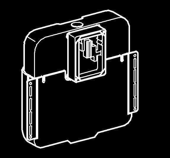
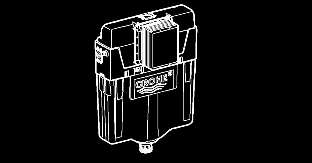
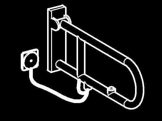
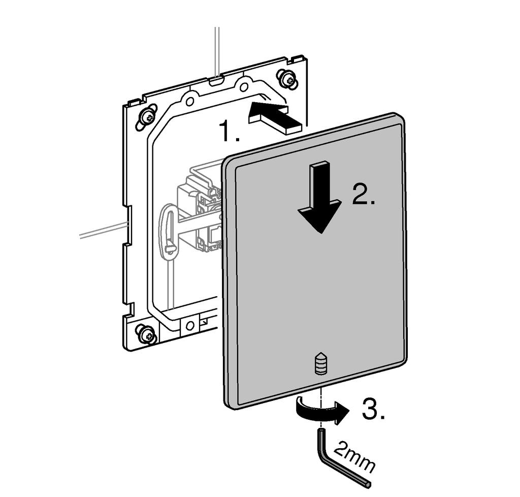
4 1 D Anwendungsbereich Einbau nur möglich bei: - Spülkasten A: 6l-Spülkasten mit AV1, Produziert ab Spülkasten B: GD2 mit AV1 siehe Klappseite I. Sicherheitsinformationen Gefahr durch beschädigte Spannungsversorgungskabel vermeiden. Bei Beschädigung muss das Spannungsversorgungskabel vom Hersteller oder dessen Kundendienst oder einer gleichermaßen qualifizierten Person ersetzt werden. Die Installation darf nur in frostsicheren Räumen vorgenommen werden. Die Steuerelektronik ist ausschließlich zum Gebrauch in geschlossenen Räumen geeignet. Das 230 V-Anschlusskabel darf nicht in den Spülkasten geführt und der Transformator darf nicht in dem Spülkasten montiert werden. Die Spannungsversorgung muss separat schaltbar sein. Nur Originalersatz- und Zubehörteile verwenden. Die Benutzung von anderen Teilen führt zum Erlöschen der Gewährleistung sowie der CE-Kennzeichnung und kann zu Verletzungen führen. Technische Daten Spannungsversorgung: V AC Hz/6,75 V DC Leistung: 4 W Spülmenge 3-9 l, einstellbar (Werkseinstellung: 6 l) Automatische Spülung 72 Stunden (Werkseinstellung: aktiviert) Schutzart - Armatur IP 59K - Schaltnetzteil IP 55 Elektrische Prüfdaten Software-Klasse A Verschmutzungsgrad 2 Bemessungs-Stoßspannung 2500 V Temperatur der Kugeldruckprüfung 100 C Die Prüfung zur elektromagnetischen Verträglichkeit (Störaussendungsprüfung) wurde mit der Bemessungsspannung und dem Bemessungsstrom durchgeführt. Zulassung und Konformität Dieses Produkt entspricht den Anforderungen der entsprechenden EU-Richtlinien. Die Übereinstimmungserklärungen können unter der folgenden Adresse angefordert werden: GROHE Deutschland Vertriebs GmbH Zur Porta 9 D Porta Westfalica Bedienung Die Spülung wird über einen Taster ausgelöst. Der Taster ist bauseitig zu beschaffen und muss potentialfrei sein. Das Produkt kann mit Tastern der Firmen Hewi, Keuco, Lehnen, Normbau, Pressalit, AMS, Deubad, Erlau FRELU und FSB oder mit handelsüblichen Tastschaltern betrieben werden. Elektroinstallation, siehe Klappseite I, Abb. [2] - [4]. Die Elektroinstallation darf nur von einem Elektro-Fachinstallateur vorgenommen werden! Dabei sind die Vorschriften nach IEC (entspr. VDE 0100 Teil 701) sowie alle nationalen und örtlichen Vorschriften zu beachten! Es darf nur wasserbeständiges Rundkabel mit 6,0 bis 8,5mm Außendurchmesser verwendet werden. Installation Es ist darauf zu achten, dass Servomotor und Elektronikmodul aus derselben Verpackungseinheit montiert werden (werkseitig kalibriert). Für die Leitung zwischen Schaltnetzteil und Elektronik ist ein Leerrohr erforderlich, siehe Klappseite I, Abb. [1]. Wand fertig verputzen und bis an Rohbauschutz verfliesen. Spülkasten A: siehe Klappseite II, Abb. [5-9]. Spülkasten B: siehe Klappseite II, Abb. [10-19]. Servomotor einbauen, siehe Klappseite III, Abb. [20a] oder [20b] - [21]. Taster montieren, siehe Klappseite III, Abb. [22a] oder [22b]. Elektronik anschließen, siehe Klappseite III, Abb. [23] - [24]. Tastermodus aktivieren, siehe Klappseite III, Abb. [25]. Taster 3 s betätigen. Signalisierung: Kontrollleuchte blinkt 4x. Abdeckplatte montieren, siehe Klappseite III, Abb. [26]. Spülmenge einstellen 1. Platte demontieren, siehe Klappseite IV, Abb. [27]. 2. Zur Änderung der Spülmenge Spülmengen-Einstellmodus aktivieren: Spannungsversorgung zur Elektronik unterbrechen und nach 5 s wieder herstellen. Taster betätigen und halten, siehe Klappseite III, Abb. [25]. Signalisierung: Kontrollleuchte blinkt schnell für 5 s. Taster lösen. Der Spülmengen-Einstellmodus ist aktiviert. Der Spülmengen-Einstellmodus wird nach 3 min automatisch beendet. 3. Taster betätigen und halten. Die Spülmengen werden durch Gruppen von Blinkzeichen, die jeweils durch eine Pause getrennt sind, über die Kontrollleuchte in der Sensorik angezeigt. 4. Spülmengen und Anzeige: Die Anzahl der Blinkzeichen der aufeinanderfolgenden Gruppen entspricht folgenden Spülmengen: - 3 = Spülmenge 3 Liter - 4 = Spülmenge 4 Liter - 5 = Spülmenge 5 Liter - 6 = Spülmenge 6 Liter (Werkseinstellung) - 7 = Spülmenge 7 Liter - 8 = Spülmenge 8 Liter - 9 = Spülmenge 9 Liter
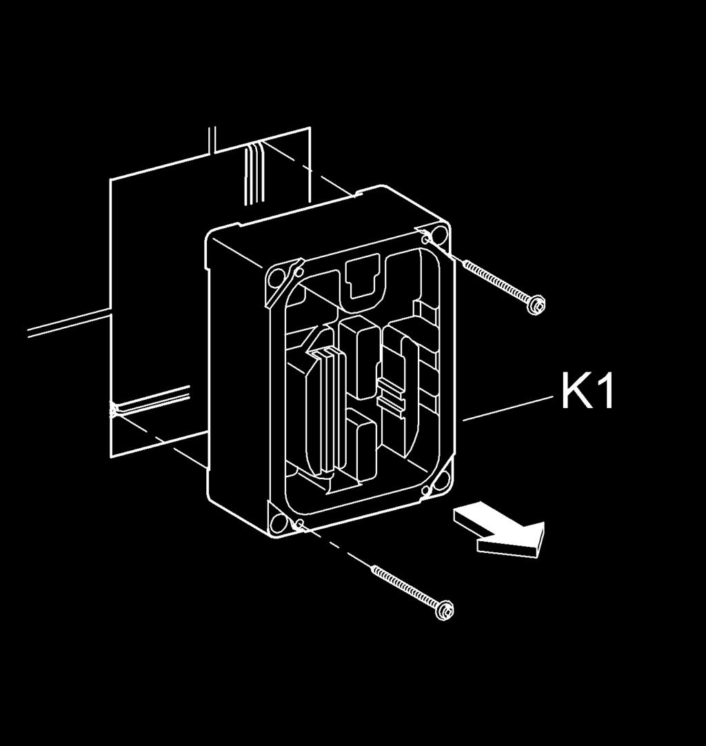
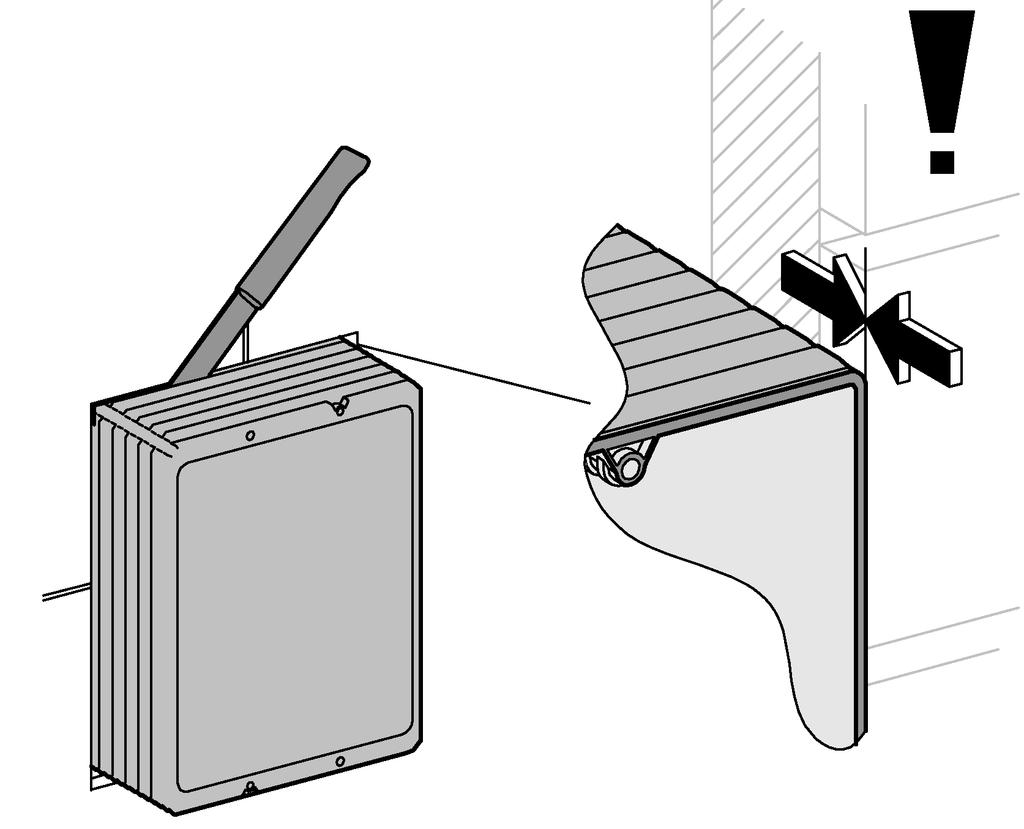
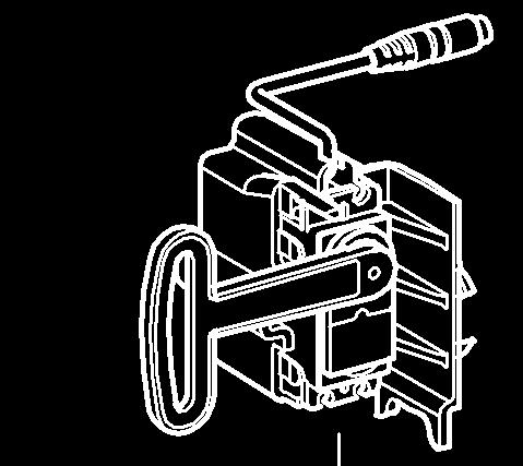
5 Nach der Gruppe mit 9 Blinkzeichen beginnt der Durchlauf von vorn. 5. Spülmenge auswählen Die Spülmenge wird ausgewählt, indem der Taster in der Pause nach einer Gruppe von Blinkzeichen losgelassen wird. Es folgt eine Spülung mit der eingestellten Menge mit erneuter Signalisierung. 6. Die Spülmenge kann innerhalb von 20 s nach der Spülung (bei Bedarf) durch eine erneute Tasterbetätigung verändert werden. Die ausgewählte Spülung wird übernommen, wenn innerhalb von 20 s nach einer Spülung keine Tasterbetätigung mehr erfolgt. Die Steuerung befindet sich im Normalmodus. Einstellungen mit Infrarot-Fernbedienung vornehmen, siehe Klappseite IV, Abb. [27] und [28]. Wartung Wasserzufuhr absperren Spannungsversorgung ausschalten Alle Teile prüfen, reinigen, evtl. austauschen Schaltnetzteil austauschen, siehe Klappseite IV, Abb. [29] Servomotor austauschen 1. Platte demontieren, siehe Klappseite IV, Abb. [27]. 2. Steckverbindungen trennen, siehe Abb. [30]. 3. Servomotor demontieren, siehe Abb. [31a] oder [31b]. 4. Neuen Servomotor kalibrieren, siehe Servomotor kalibrieren. 5. Neuen Servomotor einbauen, siehe Klappseite III, Abb. [20a] oder [20b] - [21]. 6. Abdeckplatte montieren, siehe Klappseite III, Abb. [26]. Elektronik austauschen 1. Platte demontieren, siehe Klappseite IV, Abb. [27]. 2. Steckverbindungen trennen, siehe Abb. [30]. 3. Servomotor demontieren, siehe Abb. [31a] oder [31b]. 4. Elektronikmodul austauschen, siehe Abb. [32]. 5. Servomotor kalibrieren, siehe Servomotor kalibrieren. 6. Servomotor einbauen, siehe Klappseite III, Abb. [20a] oder [20b] - [21]. 7. Abdeckplatte montieren, siehe Klappseite III, Abb. [26]. Servomotor kalibrieren Achtung: Der Servomotor muss außerhalb des Spülkastens kalibriert werden! 1. Spannungsversorgung herstellen, siehe Klappseite IV, Abb. [33]. Hierbei darf der Servomotor nicht angeschlossen sein. Die Kontrollleuchte in der Elektronik beginnt zu blinken. 2. Servomotor mit Elektronikmodul verbinden, siehe Abb. [34]. Die Kontrollleuchte in der Elektronik hört auf zu blinken und der Abgleich startet automatisch. Der Servomotor fährt dabei die Abgleichpositionen an. 3. Steckverbindungen trennen, siehe Abb. [35]. Ersatzteile, siehe Klappseite I ( * = Sonderzubehör). Pflege Die Hinweise zur Pflege dieser Armatur sind der beiliegenden Pflegeanleitung zu entnehmen. Störung / Ursache / Abhilfe Störung Ursache Abhilfe Kontrollleuchte in der Elektronik blinkt ständig nach der Kalibrierung Keine Spülung nach Tasterbetätigung Kalibrierung fehlerhaft Hindernis beim Kalibrieren Servomotor defekt Elektronik defekt Wasserzufuhr unterbrochen Servomotor defekt (Drehung wird nicht ausgeführt) Steckverbinder ohne Kontakt keine Spannung (Kontrollleuchte in der Elektronik blinkt nicht) - Kalibrierung erneut durchführen, dabei sicherstellen, dass sich kein Hindernis im Verstellbereich des Servomotors befindet - Servomotor austauschen - Elektronik austauschen - Vorabsperrung im Spülkasten öffnen - Servomotor austauschen - Steckverbinder zusammenstecken - Spannungsversorgung einschalten Schaltnetzteil defekt defekt - Schaltnetzteil austauschen Wasser fließt ununterbrochen Ablaufventil schließt nicht - Ablaufventil defekt (reparieren, austauschen), siehe Technische Produktinformation des Spülkastens Spülmenge zu gering Servomotor defekt oder nicht kalibriert (Drehung wird nicht komplett ausgeführt) Restwassermenge zu hoch Wassermenge in Spülkasten zu gering - Servomotor kalibrieren - Servomotor austauschen oder kalibrieren - Restwasserschieber am Ablaufventil nach unten schieben - Schwimmer des Füllventils nach oben drehen 2
6 GB Applications Only suitable for installation with: - Cistern A: 6-litre cistern with AV1, produced from Cistern B: GD2 with AV1 see fold-out page I. Safety notes Prevent danger resulting from damaged voltage supply cables. If damaged, the voltage supply cable must be replaced by the manufacturer or his customer service department or an equally qualified person. Installation is only possible in frost-free rooms. The control electronics are only suitable for indoor use. The 230 V connecting wire must not be fed into the cistern and the transformer must not be installed in the cistern. The voltage supply must be separately switchable. Use only genuine replacement parts and accessories. The use of other parts will result in voiding of the warranty and the CE identification, and could lead to injuries. Technical Data Voltage supply: Power consumption: Flush volume V AC Hz/6.75 V DC 4 W 3-9 l, adjustable (factory setting: 6 l) Automatic flush 72 hours (factory setting: activated) Type of protection - Fitting IP 59K - Transformer IP 55 Electrical test data Software class A Contamination class 2 Rated surge voltage 2500 V Temperature for ball impact test 100 C The test for electromagnetic compatibility (interference emission test) was performed at the rated voltage and rated current. Approval and conformity This product conforms to the requirements of the relevant EU guidelines. The conformity declarations can be obtained from the following address: GROHE Deutschland Vertriebs GmbH Zur Porta 9 D Porta Westfalica Operating Flushing is triggered by a button. The switch must be obtained on site and it must be potential free. The product can be operated with buttons from Hewi, Keuco, Lehnen, Normbau, Pressalit, AMS, Deubad, Erlau FRELU und FSB or using standard push buttons. 3 Electrical installation, see fold-out page I, Figs. [2] - [4]. Electrical installation work must only be performed by a qualified electrician. This work must be carried out in accordance with the regulations to IEC (corresponding to VDE 0100 Part 701) as well as all national and local regulations. Only water-resistant round cables with max. outside diameter of 6.0 to 8.5mm may be used. Installation Make sure that the servo motor and electronic module from the same packaged unit are installed (calibrated at the factory). A vacant tube is required for the line between transformer and electronics, see fold-out page I, Fig. [1]. Plaster and tile the wall, excluding the area of the structural shell protection. Cistern A, see fold-out page II, Figs. [5] - [9]. Cistern B, see fold-out page II, Figs. [10] - [19]. Installing the servo motor, see fold-out page III, Figs. [20a] or [20b] - [21]. Installing the button, see fold-out page III, Figs. [22a] or [22b]. Connecting the electronic, see fold-out page III, Figs. [23] - [24]. Activate button mode, see fold-out page III, Fig. [25]. Press button for 3 s. Signaling: Indicator lamp flashes 4 times. Installing the wall plate, see fold-out page III, Fig. [26]. Setting the flow volume 1. Disassemble plate, see fold-out page IV, Fig. [27]. 2. To change the flow volume acitvate the flow volume setting mode: Disconnect the power supply to the electronics and reconnect after 5 s. Press button and hold, see fold-out page III, Fig. [25]. Signaling: Indicator lamp flashes rapidly for 5 s. Release the button. The flow volume setting mode is activated. The flow volume setting mode is automatically terminated after 3 min. 3. Press button and hold. The flow volumes are indicated via the indicator lamp in the sensor system by groups of flashing signals separated by apause. 4. Flow volumes and display: The number of flashing signals of the consecutive groups corresponds to the following flow volumes: - 3 = flow volume 3 litres - 4 = flow volume 4 litres - 5 = flow volume 5 litres - 6 = flow volume 6 litres (factory setting) - 7 = flow volume 7 litres - 8 = flow volume 8 litres - 9 = flow volume 9 litres
7 After the group with 9 flashing signals, the routine starts from the beginning. 5. Selecting the flow volume: The flow volume is selected by releasing the button in the pause after a group of flashing signals. The fitting flushes immediately with the selected flow volume (the corresponding flashing signals are displayed again during flushing). 6. The flow volume can be changed within 20 seconds of flushing (if necessary) by pressing the button again. The selected flush setting is stored if the button is not pressed again within 20 seconds of flushing. Control reverts to normal mode. Make settings with infrared remote control, see fold-out page IV, Figs. [27] - [28]. Maintenance Shut off water supply Switch off voltage supply Inspect and clean all components and replace if necessary Replacing the switched-mode power supply, see fold-out page IV, Fig. [29] Replacing the servo motor 1. Disassemble plate, see fold-out page IV, Fig. [27]. 2. Disconnect plug-in connectors, see Fig. [30]. 3. Disassemble servo motor, see Fig. [31a] or [31b]. 4. Calibrate new servo motor, see Calibrating the servo motor. 5. Install new servo motor, see fold-out page III, Figs. [20a] or [20b] - [21]. 6. Install wall plate, see fold-out page III, Fig. [26]. Replacing the electronics 1. Disassemble plate, see fold-out page IV, Fig. [27]. 2. Disconnect plug-in connectors, see Fig. [30]. 3. Disassemble servo motor, see Fig. [31a] or [31b]. 4. Replace electronic module, see Fig. [32]. 5. Calibrate servo motor, see Calibrating the servo motor. 6. Install servo motor, see fold-out page III, Figs. [20a] or [20b] - [21]. 7. Install wall plate, see fold-out page III, Fig. [26]. Calibrating the servo motor Caution: The servo motor must be calibrated outside the cistern. 1. Connect voltage supply, see fold-out page IV, Fig. [33]. The servo motor must not be connected when performing this operation. The indicator lamp in the electronics begins to flash. 2. Connect servo motor to electronic module, see Fig. [34]. The indicator lamp in the electronics stops flashing and adjustment automatically starts. The servo motor moves to the adjustment positions. 3. Disconnect plug-in connectors, see Fig. [35]. Replacement parts, see fold-out page I (* = special accessories). Care For directions on the care of this fitting, please refer to the accompanying Care Instructions. Fault/ cause/ remedy Fault Cause Remedy Indicator lamp in the electronics flashing continuously after calibration No flushing after pressing the button Calibration is incorrect Obstacle during calibration Servo motor defective Electronics defective Water supply interrupted Servo motor defective (no rotation) Plug-in connector without contact No voltage (indicator lamp on back of electronics not flashing) switched-mode power supply defective - Perform calibration again, ensuring there is no obstacle in the adjustment range of the servo motor - Replace servo motor - Replace electronics - Open isolating valve in cistern - Replace servo motor - Attach plug-in connector - Switch on power supply - Replace switched-mode power supply Water flowing continuously Outlet valve not closing - Outlet valve defective (repair, replace, observe replacement part), see cistern instructions - Calibrating the servo motor Flow volume too low Servo motor defective or not calibrated (incomplete rotation) Residual flow rate too high Flow rate in cistern too low - Replace or calibrate servo motor - Push residual flow slider downwards - Turn float of filler valve further upwards 4
8
9


10 20a 23 A 20b B 1. 22a 22b III


11 a 31b A B IV
12 D & EST & LV & SK & A & info-at@grohe.com F & marketing-fr@grohe.com MAL & info-singapore@grohe.com T & info-singapore@grohe.com AUS Argent Sydney & +(02) Argent Melbourne & +(03) B & info.be@grohe.com BG & grohe-bulgaria@grohe.com CAU & info-az@grohe.com CDN & info@grohe.ca CH & info@grohe.ch CN & CY & info@grome.com CZ & grohe-cz@grohe.com DK & grohe@grohe.dk E & grohe@grohe.es FIN & teknocalor@teknocalor.fi GB & info-uk@grohe.com GR & nsapountzis@ath.forthnet.gr H & info-hu@grohe.com HK & info@grohe.hk I & info-it@grohe.com IND & customercare.in@grohe.com IS & jonst@byko.is J & info@grohe.co.jp KZ & info-cac@grohe.com LT & grohe@grohe.ee N & grohe@grohe.no NL & vragen-nl@grohe.com NZ & +09/ P & commercial-pt@grohe.com PL & biuro@grohe.com.pl RI & info-singapore@grohe.com RO & info-ro@grohe.com ROK & info-singapore@grohe.com RP & RUS & info@grohe.ru S & grohe@grohe.se SGP & info-singapore@grohe.com TR & GroheTurkey@grome.com UA & info-ua@grohe.com USA & us-customerservice@grohe.com VN & info-singapore@grohe.com AL BiH HR KS ME MK SLO SRB & adria-hr@grohe.com Eastern Mediterranean, Middle East - Africa Area Sales Office: & info@grome.com IR OM UAE YEM & grohedubai@grome.com Far East Area Sales Office: & info@grohe.com.sg /03/21
Tectron Tectron FIN EST SLO UAE RUS Design & Quality Engineering GROHE Germany
 38 934 Tectron Tectron D...1 I...13 N...25 G...37 T...49 BG...61 O...73 GB...4 NL...16 FIN...28 CZ...40 SK...52 EST...64 CN...76 F...7 S...19 PL...31 H...43 SLO...55 LV...67 UA...79 E...10 DK...22 UAE...34
Eurocube Eurocube FIN EST SLO UAE RUS Design & Quality Engineering GROHE Germany
 19 898 Eurocube 19 896 Eurocube D...1 I...2 N...3 GR...5 TR...6 BG...7 RO...9 GB...1 NL...2 FIN...4 CZ...5 SK...6 EST...8 CN...9 F...1 S...3 PL...4 H...5 SLO...7 LV...8 UA...9 E...2 DK...3 UAE...4 P...6
RS232-Verbindung, RXU10 Herstellen einer RS232-Verbindung zwischen PC und Messgerät oder Modem und Messgerät
 Betriebsanleitung RS232-Verbindung, RXU10 Herstellen einer RS232-Verbindung zwischen PC und Messgerät oder Modem und Messgerät ä 2 Operating Instructions RS232 Connection, RXU10 Setting up an RS232 connection
Parameter-Updatesoftware PF-12 Plus
 Parameter-Updatesoftware PF-12 Plus Mai / May 2015 Inhalt 1. Durchführung des Parameter-Updates... 2 2. Kontakt... 6 Content 1. Performance of the parameter-update... 4 2. Contact... 6 1. Durchführung
Produktinformation Access-Gateway. Product information Access gateway AGW 670-0
 Produktinformation Access-Gateway Product information Access gateway AGW 670-0 1 2 3 4 2 Deutsch Anwendung Access-Gateway zur physikalischen Trennung von 2 Netzwerken an einem Access-Server. Durch den
GROHE SENSIA IS KuRzANlEItuNG /ÄM /
 GROHE SENSIA IS KuRzANlEItuNG 99.0215.031/ÄM 230068/11.13 www.grohe.com Sicherheits- und Warnhinweise Bestimmungsgemäße Verwendung Das GROHE Sensia IS Dusch-WC reinigt den Analbereich und mit der Lady-Dusche
ABB i-bus EIB. EIB Power Supply Units
 ABB i-bus EIB EIB Power Supply Units Product Range Overview EIB Power Supplies ABB STOTZ-KONTAKT GmbH, 2002 - SK 029 F 02 E Product Range Overview EIB Power Supplies! EIB Power Supply, 320 ma SV/S 30.320.5!
CABLE TESTER. Manual DN-14003
 CABLE TESTER Manual DN-14003 Note: Please read and learn safety instructions before use or maintain the equipment This cable tester can t test any electrified product. 9V reduplicated battery is used in
Softwareupdate-Anleitung // AC Porty L Netzteileinschub
 1 Softwareupdate-Anleitung // AC Porty L Netzteileinschub Softwareupdate-Anleitung // AC Porty L Netzteileinschub HENSEL-VISIT GmbH & Co. KG Robert-Bunsen-Str. 3 D-97076 Würzburg-Lengfeld GERMANY Tel./Phone:
Softwareupdate-Anleitung // Porty L 600 / Porty L 1200
 Softwareupdate-Anleitung // Porty L 600 / Porty L 1200 1 Softwareupdate-Anleitung // Porty L 600 / Porty L 1200 HENSEL-VISIT GmbH & Co. KG Robert-Bunsen-Str. 3 D-97076 Würzburg-Lengfeld GERMANY Tel./Phone:
LED Treiber: Anschlussschemata LED driver: connection diagrams
 Treiber: Anschlussschemata driver: connection diagrams TCI DC MAXI JOLLY DALI für 18W (Konstantstromversorgung), 500mA, dimmbar via Taster (Push) / 1-10V / DALI 6Z1851 Sicherheitshinweise Montagehinweise
UWC 8801 / 8802 / 8803
 Wandbedieneinheit Wall Panel UWC 8801 / 8802 / 8803 Bedienungsanleitung User Manual BDA V130601DE UWC 8801 Wandbedieneinheit Anschluss Vor dem Anschluss ist der UMM 8800 unbedingt auszuschalten. Die Übertragung
SensorView 890 HSD
 SensorView 890 HSD 0290.005 SensorView 890 Übersicht Der SensorView 890 ermöglicht mit einem IP-65 Touchscreen Monitor die Konfiguration und Überwachung von einem oder mehreren Checkern der 4G Serie. SensorView
Cameraserver mini. commissioning. Ihre Vision ist unsere Aufgabe
 Cameraserver mini commissioning Page 1 Cameraserver - commissioning Contents 1. Plug IN... 3 2. Turn ON... 3 3. Network configuration... 4 4. Client-Installation... 6 4.1 Desktop Client... 6 4.2 Silverlight
EMCO Installationsanleitung Installation instructions
 EMCO Installationsanleitung Installation instructions Installationsanleitung Installation instructions Digitalanzeige digital display C40, FB450 L, FB600 L, EM 14D/17D/20D Ausgabe Edition A 2009-12 Deutsch...2
Schutzart IP 20 protection degree IP 20 18
 MODUL L 196 Pendelleuchte / suspended luminaire MONTAGE / MOUNTING 010-614. 009-282. 010-095 direktstrahlend / direct beam 010-613. 009-281. 010-094 mit Indirektlichtanteil / with indirect light component
Kuhnke Technical Data. Contact Details
 Kuhnke Technical Data The following page(s) are extracted from multi-page Kuhnke product catalogues or CDROMs and any page number shown is relevant to the original document. The PDF sheets here may have
VDE Prüf- und Zertifizierungsinstitut Zeichengenehmigung
 VDE Prüf- und Zertifizierungsinstitut Zeichengenehmigung Ausweis-Nr. / Certificate No. 40040851 Blatt / Page 2 Name und Sitz des Genehmigungs-Inhabers / Name and registered seat of the Certificate holder
Cable Tester NS-468. Safety instructions
 Cable Tester NS-468 Safety instructions Do not use the cable tester NS-468 if it is damaged. This device is only for use inside dry and clean rooms. This device must be protected from moisture, splash
VDE Prüf- und Zertifizierungsinstitut Zeichengenehmigung
 2 Konverter, elektronisch Convertor, electronic Typ(en) / Type(s): 01) ET-PARROT 70/220-240 I 02) ET-BI 70/220-240 S 03) ET-PARROT 105/220-240 I 04) ET-BI 105/220-240 S 05) ET-PARROT 105/220-240 I/G 06)
Bedienungsanleitung. User Manual
 Bedienungsanleitung Seite: -3 User Manual LightmaXX 5ive STAR LED LIG0009669-000 Page: 4-5 Lieber Kunde, vielen Dank das Sie sich für ein Produkt von LightmaXX entschieden haben. In der folgenden Anleitung
Schnell-Start-Anleitung Quick Start Guide
 Schnell-Start-Anleitung Quick Start Guide 3 1. Cube anschließen Schließen Sie den Cube an die Stromversorgung an. Verbinden Sie den Cube mit dem Router. Die Power- und die Internet-LED beginnen zu blinken,
1 Allgemeine Information
 1 Allgemeine Information ACHTUNG! Der Betriebsdruck der Klasse 867 ist 6 bar. Sollte der Druck Ihrer Versorgungsleitung höher als 6 bar sein, muss der Druck an der Versorgungseinheit der Nähmaschine auf
Hazards and measures against hazards by implementation of safe pneumatic circuits
 Application of EN ISO 13849-1 in electro-pneumatic control systems Hazards and measures against hazards by implementation of safe pneumatic circuits These examples of switching circuits are offered free
Thielert Aircraft Engines GmbH Platanenstrasse Lichtenstein, Germany
 Bild 1 Vor Modifikation Bild 2 Nach Modifikation Page 2 / 6 3. Haupt-, Excitation- und FADEC Sicherheits-Batterie anklemmen 4. Funktionstest ACHTUNG: Folgende Tests sind nur am Boden durchzuführen! - Motor
Auf Spannungsfreiheit prüfen! / De-energized and check zero-potential!
 Installationshinweise zum Einbau der LED-Röhre Dragon mit T8/G13 Sockel (Austausch) Installation Instruction for LED tube Dragon with T8/G13 socket (Replacement) A-1. Einzelschaltung mit KVG / VVG 1) Single
CS 80 MAGNEO Zusatzset Sensorik add. set for safety sensor DORMA IRIS ON ACTIV8 ONE ON. Jupiter. Art Motion
 WN 0 0 /0.. IS ACTIV E Presence Sensor Art Motion Nutzen Sie die beiliegende Bohrschablone des Herstellers. = = = = Please use the enclosed drill template provided by the manufacturer. oben top side unten
Integrated Control Unit for CL-PU-KST... Grease Pumps. Integriertes Steuergerät für Fettpumpen CL-PU-KST...
 Integrated Control Unit for CL-PU-KST... Grease Pumps Integriertes Steuergerät für Fettpumpen CL-PU-KST... Electric grease pumps, Modell: CL-PU-KST... 12 / 24VDC Series 24/12 V DC Elektrische Fettpumpe,
Schutzart IP 20 protection degree IP 20 18
 MODUL L 196 Pendelleuchte / suspended luminaire MONTAGE / MOUNTING 010-614. 009-282. 010-095 24 V DC / 40 W 010-613. 009-281. 010-094 24 V DC / 45 W Schutzart IP 20 protection degree IP 20 18 max. 1500
LED Treiber: Anschlussschemata LED driver: connection diagrams
 ED Treiber: Anschlussschemata ED driver: connection diagrams TCI DC JOY MD für 18W ED (Konstantstromversorgung), 500mA, dimmbar via Phasenabschnittsdimmer / Taster (Push) 6Z 18 50 Sicherheitshinweise Montagehinweise
Serviceinformation Nr. 02/11
 Serviceinformation Nr. 02/11 vom: 06.10.2011 von: BAM 1. Software Navigator und Release Notes Auf unserer Homepage unter www.idm-energie.at/de/navigator-software.html steht ab sofort eine neue Version
SmartClass Firmware-Update Vorgehensweise
 Benutzeranweisungen SmartClass Firmware-Update Vorgehensweise 2008.01 (V 1.x.x) Deutsch Please direct all enquiries to your local JDSU sales company. The addresses can be found at: www.jdsu.com/tm-contacts
2 IP X4 TAI/LED IP44, CH IP24. Montage-Anleitung Instructions de montage Assembling instructions. 225 cm. 60 cm 0
 Montage-Anleitung Instructions de montage Assembling instructions TAI/LED IP, CH IP Sensor-Schalter aussen unten rechts Interrupteur sensitif en bas à l'extérieur à droite Sensor switch outside right below
MultiPortSwitch. VGA Umschalter. Version 1.0 As of April 19 th 2004 Subject to change!
 MultiPortSwitch VGA Umschalter Version 1.0 As of April 19 th 2004 Subject to change! Document version: Version Date Name Comment 1.00 29.03.2004 J. Klein Compiled Distributed by: idata industrielle Datensysteme
USB -> Seriell Adapterkabel Benutzerhandbuch
 USB -> Seriell Adapterkabel Benutzerhandbuch 1. Produkt Eigenschaften 1 2. System Vorraussetzungen 1 3. Treiber Installation (Alle Windows Systeme) 1 4. Den COM Port ändern 2 5. Einstellen eines RS232
2 IP X4 WLS/FL IP24. Montage-Anleitung Instructions de montage Assembling instructions. 225 cm. 60 cm 0
 WLS/FL IP Arbeiten an den elektrischen Anlagen dürfen nur von autorisierten Fachleuten nach den örtlichen Vorschriften ausgeführt werden. Für nicht fachgerechte Installation wird jegliche Haftung abgelehnt.
Die Dokumentation kann auf einem angeschlossenen Sartorius Messwertdrucker erfolgen.
 Q-App: USP V2 Bestimmung des Arbeitsbereiches von Waagen gem. USP Kapitel 41. Determination of the operating range of balances acc. USP Chapter 41. Beschreibung Diese Q-App ist zur Bestimmung des Arbeitsbereiches
Order Number Bestellnummer. Hand crimp tool Handcrimpzange Positioner Einsatz Positioner Einsatz. Order Number. Bestellnummer
 Crimpingtools for Miniature Connectors Crimpwerkzeuge für Miniatursteckverbinder Hand Crimp Tool M22520/2-01 for Machined Contacts Handcrimpzange M22520/2-01 für gedrehte Kontakte Die / Einsatz Hand crimp
IP X4 MOA/SL/FL IP44, CH IP24. Montage-Anleitung Instructions de montage Assembling instructions. 225 cm. 60 cm 0
 MOA/SL/FL IP44, CH IP4 Arbeiten an den elektrischen Anlagen dürfen nur von autorisierten Fachleuten nach den örtlichen Vorschriften ausgeführt werden. Für nicht fachgerechte Installation wird jegliche
Der Adapter Z250I / Z270I lässt sich auf folgenden Betriebssystemen installieren:
 Installationshinweise Z250I / Z270I Adapter IR USB Installation hints Z250I / Z270I Adapter IR USB 06/07 (Laden Sie den Treiber vom WEB, entpacken Sie ihn in ein leeres Verzeichnis und geben Sie dieses
iid software tools QuickStartGuide iid USB base driver installation
 iid software tools QuickStartGuide iid software tools USB base driver installation microsensys Nov 2016 Introduction / Einleitung This document describes in short form installation of the microsensys USB
Cleanroom Fog Generators Volcano VP 12 + VP 18
 Cleanroom Fog Generators Volcano VP 12 + VP 18 Description & Functional Principle (Piezo Technology) Cleanrooms are dynamic systems. People and goods are constantly in motion. Further installations, production
Honeywell AG Hardhofweg. D-74821 Mosbach MU1H-1220GE23 R1001
 BA 95 Einbau-Anleitung Installation Instructions Einbau Installation Einbaubeispiel Installation example Ablaufleitung vorsehen Install discharge pipework Durchflussrichtung beachten! Consider direction
LED Konverter: Anschlussschemata LED converter: connection diagrams
 LED Konverter: Anschlussschemata LED converter: connection diagrams TCI DC MAXI JOLLY DALI 48V DC, 48W (Konstantspannungsversorgung), dimmbar via Taster (Push) / 1-10V / DALI 6Z 48 10 00 Sicherheitshinweise
4CH AHD Digital Video Recorder kit
 4CH AHD Digital Video Recorder kit with 4x 720P outdoor fixed Lens cameras Quick Installation Guide DN-16120 Connect directly to your DVR Connecting your cameras to your DVR: 1. Find the 60ft. BNC cable,
Contact 1600 QUICK REFERENCE GUIDE GUIDE D UTILISATION BEDIENUNGSANLEITUNG GUÍA DE REFERENCIA RÁPIDA GUIDA RAPIDA. www.sonybiz.net CHANGING THE WAY
 Contact 1600 CHANGING THE WAY QUICK REFERENCE GUIDE GUIDE D UTILISATION BEDIENUNGSANLEITUNG BUSINESS GUÍA DE REFERENCIA RÁPIDA GUIDA RAPIDA COMMUNICATES www.sonybiz.net GB Getting started STEP 1 Turning
C R 2025 C LOSE PUSH OPEN
 3V C R 2025 C LOSE PUSH OPEN ) ) ) 25 222 3V C R 2025 C LOSE PUSH OPEN 25 222 3V C R 2025 C LOSE PUSH OPEN 25 222 Den här symbolen på produkten eller i instruktionerna betyder att den elektriska
E/A-Bedieneinheit. I/O Control unit 658552 DE/GB 08/02
 E/A-Bedieneinheit I/O Control unit 527429 658552 DE/GB 08/02 Best.-Nr.: 658552 Benennung: DATENBLATT Bezeichnung: D:LP-BED.EINH.-E/A-DE/GB Stand: 08/2002 Autoren: Christine Löffler Grafik: Doris Schwarzenberger
Anleitung zur Verwendung des Update-Tools für
 English version see below (page 10) Anleitung zur Verwendung des Update-Tools für - KW DDC Steuergeräte - KW DDC WLAN Module - KW DLC Steuergeräte - KW DLC WLAN Module Bitte beachten Sie: jedes Steuergerät
LED-TRAFOS UND DIMM-SYSTEME / LED-DRIVERS 12.1 MEANWELL DRIVER 12.2 BASIS DRIVER 12.3 RGB / DIMM-SYSTEME 12.4 RAKO DIMMING. Seite 12.
 LED-TRAFOS UND DIMM-SYSTEME / LED-DRIVERS 12 12.1 MEANWELL DRIVER 12.2 BASIS DRIVER 12.3 RGB / DIMM-SYSTEME 12.4 RAKO DIMMING Seite 12.0 LTG Deutschland LED-DRIVERS UND DIMMSYSTEME Trafos und Dimmsysteme
NEWSLETTER. FileDirector Version 2.5 Novelties. Filing system designer. Filing system in WinClient
 Filing system designer FileDirector Version 2.5 Novelties FileDirector offers an easy way to design the filing system in WinClient. The filing system provides an Explorer-like structure in WinClient. The
Westfalia Bedienungsanleitung. Nr
 Bedienungsanleitung Nr. 107375 Bedienungsanleitung Satelliten Finder RL-TC-0101 Artikel Nr. 54 25 97 Instruction Manual Satellite Finder RL-TC-0101 Article No. 54 25 97 Benutzung Funktionsumfang Regelbare
CAN-Bus RPM adapter. User Manual Anwender-Beschreibung
 CAN-Bus RPM adapter COT02 User Manual Anwender-Beschreibung Stand: 12.02.03 GRABAU Computertechnik GmbH Elsener Str. 30 33102 Paderborn Tel: +49 5251 1367-0 Fax: +49 5251 1367-30 Email: info@grabau.de
5XR2441A0A0... 5XR2442A0A0... 5XR2420A1A0W 5XR2420A1A0S 5XR2400A0A1S 5XR2400A0A2S 5XR2410A0A0W 5XR2410A0A0S
 Siteco Beleuchtungstechnik GmbH Georg-Simon-Ohm-Straße 0 83301 Traunreut, Germany Phone: +49 8669 / 33-844 Fax: +49 8669 / 863-2944 mail: technicalsupport@siteco.de Internet: www.siteco.com Montage- /
Installation Instructions
 EN DE Installation Instructions WLAN Installation Kit, 300 Mbps, 5 GHz, 16 dbi AK-4 Wireless Kit Scope of delivery Junction box AK-4 (1x) 1 Connection board AK-4 CB with 12VDC power supply unit (1x) 2
TRANSMITTER SPECIFICATION / SENDER SPEZIFIKATIONEN RECEIVER SPECIFICATION / EMPFÄNGER SPEZIFIKATIONEN
 TRANSMITTER SPECIFICATION / SENDER SPEZIFIKATIONEN Channels: 2 Model type: car/boat RF power: less than 20 dbm Code type: digital Sensitivity: 1024 Low voltage warning:yes (less than 4,5 V) DSC port: yes
Technical Support Information No. 123 Revision 2 June 2008
 I IA Sensors and Communication - Process Analytics - Karlsruhe, Germany Page 6 of 10 Out Baking Of The MicroSAM Analytical Modules Preparatory Works The pre-adjustments and the following operations are
Art.-Nr. 4450900300 greentea. Art.-Nr. 4450900200 whitemusk MAGICUS. 1 Stück/piece 2,5. 4 x 4 x 4 x. 1 x
 MAGICUS Art.-Nr. 4450900300 greentea 1 Stück/piece Art.-Nr. 4450900200 whitemusk 2,5 4 x 4 x 4 x 1 x 1. 2. 1 x Option 2 Option 1 3. 1 3 4 2 4. I AUTO RUN Mo Tu We Th Fr Sa Su OK + Clear R 230VAC, 50Hz
Umschaltadapter/ Changeover / Trennadapter Disconnection Adapter für LSA-PLUS NT for LSA-PLUS NT. Montageanweisung Mounting Instructions
 Umschaltadapter/ Changeover / Trennadapter Disconnection Adapter für LSA-PLUS NT for LSA-PLUS NT Montageanweisung Mounting Instructions Der Umschalter dient zum unterbrechungsfreien Umschalten von Installations-drähten
v i r t u A L C O M P o r t s
 v i r t u A L C O M P o r t s (HO720 / HO730) Installieren und Einstellen Installation and Settings Deutsch / English Installieren und Einstellen des virtuellen COM Ports (HO720 / HO730) Einleitung Laden
Nachdem Sie die Datei (z.b. t330usbflashupdate.exe) heruntergeladen haben, führen Sie bitte einen Doppelklick mit der linken Maustaste darauf aus:
 heruntergeladen haben, führen Sie bitte einen Doppelklick mit der linken Maustaste darauf aus:") Deutsch 1.0 Vorbereitung für das Firmwareupdate Vergewissern Sie sich, dass Sie den USB-Treiber für Ihr Gerät installiert haben. Diesen können Sie auf unserer Internetseite unter www.testo.de downloaden.
Deutsch 1.0 Vorbereitung für das Firmwareupdate Vergewissern Sie sich, dass Sie den USB-Treiber für Ihr Gerät installiert haben. Diesen können Sie auf unserer Internetseite unter www.testo.de downloaden.
(825M) 2-Draht-Sender
 2-Draht-Sender") Kamera SKS Bussystem 300004 (825M) 2-Draht-Sender 1. Installation Gefahr für Personen durch einen elektrischen Schlag. Verbrennungsgefahr, Geräteschäden und Fehlfunktionen. Bei der Installation sind die
Kamera SKS Bussystem 300004 (825M) 2-Draht-Sender 1. Installation Gefahr für Personen durch einen elektrischen Schlag. Verbrennungsgefahr, Geräteschäden und Fehlfunktionen. Bei der Installation sind die
CONTROLLER RECEIVER REPEATER PAIRING SLIM CLIP
 ANLEITUNGEN // INSTRUCTIONS CONTROLLER RECEIVER REPEATER PAIRING SLIM CLIP BEDIENUNGSANLEITUNG // INSTRUCTION MANUAL MONTAGEANLEITUNG // ASSEMBLY INSTRUCTION MONTAGEANLEITUNG // ASSEMBLY INSTRUCTION KOPPLUNG
INSTALLATION AND OPERATING INSTRUCTIONS FOR LPS203-M LPS203-M 操 作 指 示
 BEDIENUNGSANLEITUNG To comply with the published safety standards, the following must be observed when using this power supply. Um den zur Zeit gültigen Sicherheitsbestimmungen zu genügen, müssen die nachstehenden
Hama GmbH & Co KG Postfach Monheim/Germany Tel. +49 (0)9091/502-0 Fax +49 (0)9091/
9091/502-0 Fax +49 (0)9091/") www.hama.de Hama GmbH & Co KG Postfach 80 86651 Monheim/Germany Tel. +49 (0)9091/502-0 Fax +49 (0)9091/502-274 hama@hama.de www.hama.de 00062248-05.05 Multimedia Kit für/for Audi Naviplus/ VW/Seat/Skoda
www.hama.de Hama GmbH & Co KG Postfach 80 86651 Monheim/Germany Tel. +49 (0)9091/502-0 Fax +49 (0)9091/502-274 hama@hama.de www.hama.de 00062248-05.05 Multimedia Kit für/for Audi Naviplus/ VW/Seat/Skoda
Radiophone. Antares T60. Bedienungs- und Einbauanleitung
 Radiophone ntares T60 edienungs- und Einbauanleitung EINUNLEITUNG D Sicherheitshinweise Für die Dauer der Montage und des nschlusses beachten Sie bitte folgende Sicherheitshinweise. - Minuspol der atterie
KOMPETENZBROSCHÜRE Competence brochure
 KOMPETENZBROSCHÜRE Competence brochure We switch the power! Hauptschalter Not-Aus-Schalter S-Reihe mit Unterspannungsauslösung Main switches Emergency-off switches S series with undervoltage release Schalter
Serviceinformation Nr. 05/10
 Serviceinformation Nr. 05/10 vom: 05.08.2010 von: GRC 1. Strömungswächter für Grundwasseranlagen Ab sofort können anstelle der Seikom Strömungswächter GF Schwebekörper Durchflussmesser mit Reed Kontakt
ISLIKER MAGNETE AG - CH-8450
 GI-50.10 GI-50.10 1 / Hub / stroke = 10mm 110.5 9 68.5 3x M O 0 M6 18 SW5 O50 O6 Magnet bestromt gezeichnet Solenoid illustrated in energised position 6 max. Hub / stroke = 10mm 110.5 39 68.5 3x M O 0
Batterie-Identifikations-Modul EL-BIM
 Bedienungs- und Montageanleitung Batterie-Identifikations-Modul EL-BIM 1.0 Allgemeines Das Batterie-Identifikations-Modul EL-BIM ermöglicht eine eindeutige Zuordnung von Ladevorgang und Batterie in den
FIRMWARE UPDATE TAPMOTION TD
 FIRMWARE UPDATE TAPMOTION TD CMP-SPF TO WHOM IT MAY CONCERN Seite 1 von 9 Inhalt / Overview 1. Firmware überprüfen und Update-file auswählen / Firmware check and selection of update file 2. Update File
MU-307 A SAFETY INSTRUCTIONS SICHERHEITSHINWEISE FEATURES MERKMALE
 SAFETY INSTRUCTIONS Read all safety instruction before operating the amplifiers. 1. Install equipment as follow condition: - Install at flat place, not bending curved. - Do not install near the water and
Bedienungsanleitung. User Manual
 Bedienungsanleitung Seite: 1-6 User Manual LightmaXX COMPLETE PAR 64 12x 12 Watt RGBAW-UV Page: 7-11 Lieber Kunde, vielen Dank das Sie sich für ein Produkt von LightmaXX entschieden haben. In der folgenden
Please do not use in live circuits. When the POWER LED does not light, you must change the battery for testing.
 L A N / U S B C A B L E T E S T E R I n s t a l l a t i o n 1 2 9 9 6 4 1. I n t r o d u c t i o n The LAN/USB Cable Tester is designed to easily read the correct cable pin out configuration. The cables
Uhrenbeweger Watch winders. Crystal
 Uhrenbeweger Watch winders Crystal Sehr geehrter Kunde, unsere Uhrenbeweger sind so konstruiert, dass sie trotz kompakter Abmessungen nur geringe Laufgeräusche verursachen. Jeder Antrieb erzeugt jedoch
Produktinformation _185PNdeen
 Produktinformation 201407_185PNdeen Solldaten-UPGRADE Juli 2014 WA 900 / 920 / 020 / 950 / 970 CURA S 800 / 860 / 060 / 900 / 960 WAB01 / WAB 02 CCT CURA R1200 / CURA R2000/ API R2000 BOSCH FWA 51x Auf
HEAG 151, 152, 153, 154 Digital Converter
 Montage- und Betriebsanleitung Installation and operating instructions MB095-11055704 Baumer_HEAG151-152-153-154_II_DE-EN (16A1) HEAG 151, 152, 153, 154 Digital Converter 1-2 Allgemeine Hinweise - Funktionsweise
SanStore: Kurzanleitung / SanStore: Quick reference guide
 SanStore Rekorder der Serie MM, MMX, HM und HMX Datenwiedergabe und Backup Datenwiedergabe 1. Drücken Sie die Time Search-Taste auf der Fernbedienung. Hinweis: Falls Sie nach einem Administrator-Passwort
ReadMe zur Installation der BRICKware for Windows, Version 6.1.2. ReadMe on Installing BRICKware for Windows, Version 6.1.2
 ReadMe zur Installation der BRICKware for Windows, Version 6.1.2 Seiten 2-4 ReadMe on Installing BRICKware for Windows, Version 6.1.2 Pages 5/6 BRICKware for Windows ReadMe 1 1 BRICKware for Windows, Version
Release Notes BRICKware 7.5.4. Copyright 23. March 2010 Funkwerk Enterprise Communications GmbH Version 1.0
 Release Notes BRICKware 7.5.4 Copyright 23. March 2010 Funkwerk Enterprise Communications GmbH Version 1.0 Purpose This document describes new features, changes, and solved problems of BRICKware 7.5.4.
DC/AC INVERTER 80VA. Eingangsspannungsbereich Input voltage range 11 14V DC
 AC-RIDER 80VA WWW.AC-RIDER.COM TÜV Rheinland geprüfte Sicherheit Besondere Merkmale Features 12 VDC Eingang 12 VDC input Hoher Wirkungsgrad High efficiency Überlast / Kurzschlußfest Overload / Short-circuit
SERVICE INFORMATION NO. SID4-020/1
 Diamond Aircraft Industries G.m.b.H. DAI SID4-020/1 N.A. Otto-Straße 5 Page 1 of 2 A-2700 Wiener Neustadt 06-Sep-2004 SERVICE INFORMATION NO. SID4-020/1 SUPERSEDES SERVICE INFORMATION NO. SID4-020 I. TECHNICAL
Bedienungsanleitung. USB-Adapter-Box auf BUS-2 o. seriell Art.-Nr. 013467.10 D GB 2008-10-01 P02318-03-002-01. Änderungen vorbehalten
 Bedienungsanleitung USB-Adapter-Box auf BUS-2 o. seriell Art.-Nr. 013467.10 P02318-03-002-01 2008-10-01 D GB Änderungen vorbehalten 2 Bedienungsanleitung USB-Adapter-Box auf BUS-2 o. seriell 1. Einsatz
VDE Prüf- und Zertifizierungsinstitut Zeichengenehmigung
 Blatt / page 2 Dieses Blatt gilt nur in Verbindung mit Blatt 1 des sausweises Nr.. This supplement is only valid in conjunction with page 1 of the. Einbauteil für IT Geräte Component for IT equipment Typ(en)
Bedienungsanleitung Manual
 Bedienungsanleitung Manual RX-EP-U UHF Empfänger (3) Multi-Schalter (2) Taste 2 Ohrbügel Das RX-EP-U ist ein PC-programmierbarer UHF-Empfänger mit 99 verfügbaren Speicherkanälen und 38 CTCSS- Kodierungen.
Beschreibung. Process Description: Sartorius Bestellnummer / Order No.:
 Q-App: USP Advanced Bestimmung des Arbeitsbereiches von Waagen gem. USP Kapitel 41 mit Auswertung über HTML (Q-Web) Determination of the operating range of balances acc. USP Chapter 41 with evaluation
Load balancing Router with / mit DMZ
 ALL7000 Load balancing Router with / mit DMZ Deutsch Seite 3 English Page 10 ALL7000 Quick Installation Guide / Express Setup ALL7000 Quick Installation Guide / Express Setup - 2 - Hardware Beschreibung
Deutsch: REPARATURANWEISUNG
 DE: Diese Anweisung ist in zwei Sprachen verfügbar. ENG: This instruction is available in two languages. Deutsch: REPARATURANWEISUNG English: REPAIR INSTRUCTION Dok.-Nr. RA L4.00-00 Sprachen-2-Deckblatt
EL-21SY. 2 in, 1 out v1.3 HDMI Switcher OPERATION MANUAL
 EL-21SY 2 in, 1 out v1.3 HDMI Switcher OPERATION MANUAL Table of Contents 1. Introduction 1 2. Features 1 3. Package Contents 1 4. Operation Controls and Functions 2 4.1 Front Panel Diagram 2 4.2 Rear
Anleitung zur Schnellinstallation TFM-560X YO.13
 Anleitung zur Schnellinstallation TFM-560X YO.13 Table of Contents Deutsch 1 1. Bevor Sie anfangen 1 2. Installation 2 Troubleshooting 6 Version 06.08.2011 1. Bevor Sie anfangen Packungsinhalt ŸTFM-560X
VDE Prüf- und Zertifizierungsinstitut Zeichengenehmigung
 Blatt / page 2 Dieses Blatt gilt nur in Verbindung mit Blatt 1 des sausweises Nr.. This supplement is only valid in conjunction with page 1 of the. Durchflußerwärmer, geschlossen Instantaneous water heater,
Produktänderung EPCOS DeltaCap Kondensatoren für die Blindleistungskompensation
 06.03.2015 Produktänderung EPCOS DeltaCap Kondensatoren für die Blindleistungskompensation Bei einigen EPCOS DeltaCap TM Leistungskondensatoren der Baureihen B32300A* und B32303A* für die Blindleistungskompensation
DATENBLATT / FACT SHEET
 DATENBLATT / FACT SHEET ART.-NR: SQUEEZE 3 PENDELLEUCHTE / SUSPENDED LUMINAIRE LED.next höheneinstellbare Pendelleuchte für den Home- und Loungebereich. Einzeln oder aber auch in Gruppen anwendbar. Lichtaustritt
VDE Prüf- und Zertifizierungsinstitut Zeichengenehmigung
 Blatt / page 2 Dieses Blatt gilt nur in Verbindung mit Blatt 1 des sausweises Nr.. This supplement is only valid in conjunction with page 1 of the. Espresso-Kaffeebereiter mit Mühle Espresso coffee maker
VDE Prüf- und Zertifizierungsinstitut Zeichengenehmigung
 usweis-nr. / Blatt / Page 2 ktenzeichen / File ref. Dieses Blatt gilt nur in Verbindung mit Blatt 1 des sausweises Nr.. This supplement is only valid in conjunction with page 1 of the. Terrestrische Photovoltaik-Module
1. Download der benötigten Software Version 2. Speichern Sie das easytouch Update auf einem leeren USB-Sick (FAT) (max 2 GB) P3 / Mini.
 (max 2 GB) P3 / Mini.") easytouch 1.3.0.20 (2.3.0.20): (german) (for English see below please) Für die easytouch Geräteserie ist eine neue Softwareversion 1.3.0.20 & 2.3.0.20 erhältlich und zum Download auf unserer deutschen
easytouch 1.3.0.20 (2.3.0.20): (german) (for English see below please) Für die easytouch Geräteserie ist eine neue Softwareversion 1.3.0.20 & 2.3.0.20 erhältlich und zum Download auf unserer deutschen
E P L A N - DECKBLATT E P L A N - COVER
 P L N - KLTT P L N - OVR HRSTLLR: manufacturer: oll & Kirch ilterbau GmbH Siemensstraße 0-4 5043 Kerpen nlage: plant: Verdrahtungsfarben: color of transmission: Vollautomatischer Rückspülfilter Typ 68/69/644
Installation manual / Montageanleitung WBC2 splice patch with Fibertray Spleissung/Rangierung mit Fibertray
 Content of Assembly Instruction I. Required tools II. Required parts III. Installation Inhalt der Montageanleitung I. Benötigte Werkzeuge II. Benötigte Teile III. Installation I. Required tools: I. Benötigtes
Car Adapter photolab 6xxx
 Bedienungsanleitung Mit dem können Sie die Spektralphotometer und mobil und unabhängig von der örtlichen Stromversorgung betreiben. Dafür benötigen Sie eine 12 V - Spannungungsversorgung wie z. B. eine
300Mbps Wireless Outdoor PoE Access Point/Bridge Quick Installation Guide
 LevelOne WAB-5120 300Mbps Wireless Outdoor PoE Access Point/Bridge Quick Installation Guide English Deutsch - 1 - Table of Content English... - 3 - Deutsch... - 9 - This guide covers only the most common