Síťový usměrňovač NG
|
|
|
- Gitta Krause
- vor 8 Jahren
- Abrufe
Transkript
1 Produktinformation Netzgleichrichter NG Line rectifier NG Redresseur secteur Alimentatore Netgelijkrichter Strømforsyning Nätaggregat Síťový usměrňovač

2 1
3 2 3 4/5
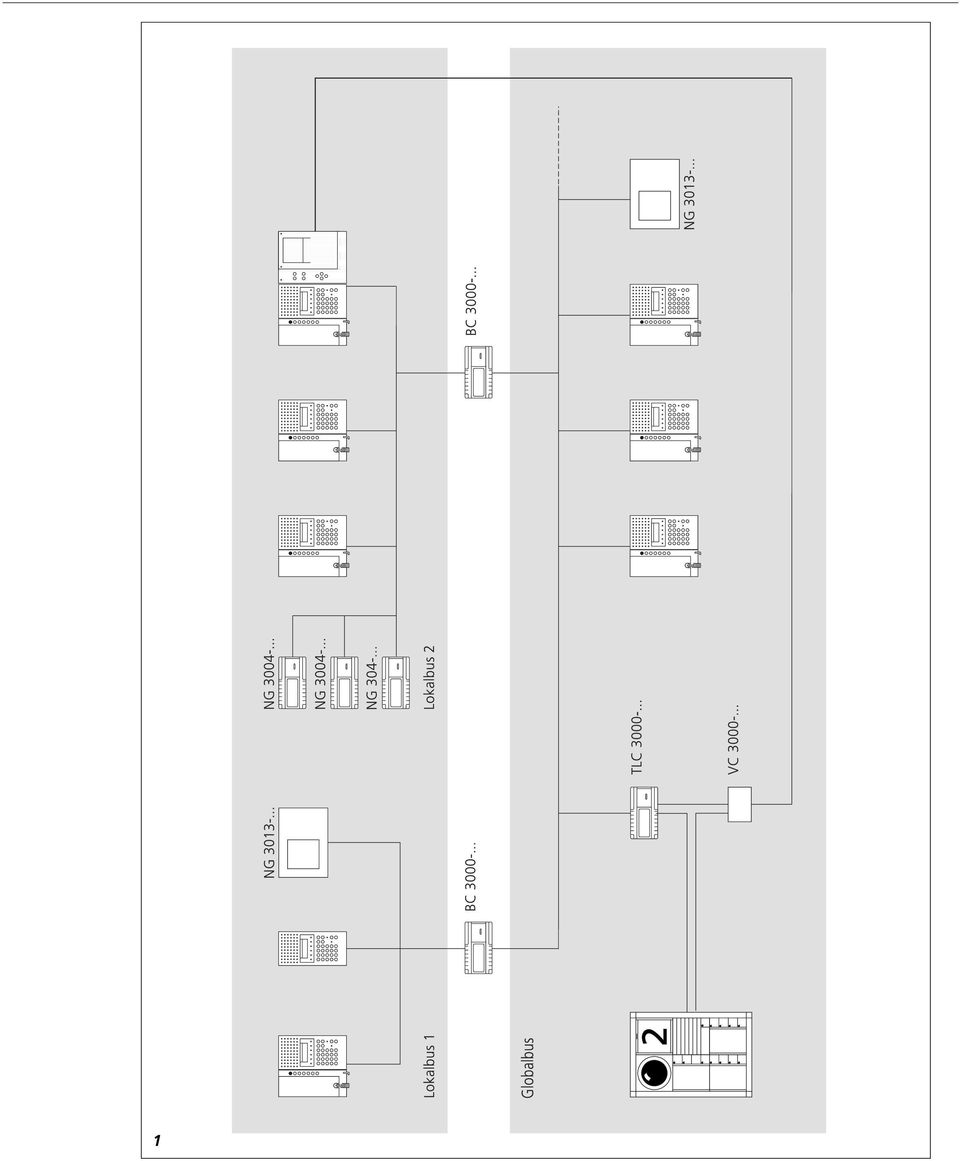
4 Deutsch Montage Hinweis Der Netzgleichrichter wird auch in Verbindung mit Video, zur Versorgung sämtlicher Videokomponenten, eingesetzt. Weitere Angaben zum Gerät, Wirkungsweise und Schaltpläne für Video-Sprechanlagen siehe Video-Systeme Teil 1 und Teil 2, Ausgabe A. Anwendung Für Anlagen im sprachgesteuerten Gegensprechbetrieb in Verbindung mit Siedle Intercom SIC zur Versorgung von max. 4 Anschlusseinheiten. Wirkungsweise, Gerätebedarf und Schaltpläne siehe Siedle Intercom Planung und Installation. 1 Anlagen Aufbau Eine Anlage besteht in ihrer einfachsten Form aus einem Bus (Globalbus), an dem bis zu 99 Geräte angeschlossen werden können. Wird eine Anlage so aufgebaut, dass mehr Geräte erforderlich sind, oder dass eine Aufteilung der Anlage erforderlich wird, werden zusätzlich Busse (Lokalbusse) benötigt. Jeder Lokalbus kann auch bis zu 99 Geräte enthalten. Von den 99 zugelassenen Geräten pro Bus dürfen jedoch nur 25 Geräte sprechende Teilnehmer sein. Der max. Ausbau einer Anlage besteht aus einem Globalbus mit max. 99 Geräten und bis zu 25 Lokalbussen mit max. je 99 Geräten. Zum Anschluss eines Lokalbusses an einen Globalbus wird immer ein Bus-Controller BC benötigt. Installation Achtung! Einbau und Montage elektrischer Geräte dürfen nur durch eine Elektro-Fachkraft erfolgen. 2 6 Wichtig! Bitte die Norm DIN EN beachten! In der Gebäudeinstallation muss ein allpoliger Netzschalter mit einer Kontaktöffnung von mindestens

5 English Montage Technische Daten für NG Primär 120 V/60 Hz, +6%-10% Sekundär 27 V DC 0,5 A geregelt (bei max. Belastung min. 26 V DC) Schutzart IP 20 Dimension 180 x 89 x 60 Gewicht 1,2 kg Hinweis Die 120 V-Version NG darf nur in einem geschlossenen Schaltschrank betrieben werden. Die alleinige Abdeckung mit ZAP ist nicht ausreichend. Die 120 V-Version darf nur in Verbindung mit ITE Geräten verwendet werden. (Information Technology Equipment) 4 Note The line rectifier is also used in connection with video to supply all video components. For further information about the unit, how it operates and wiring diagrams for video communication systems, see Video Systems part 1 and part 2, edition A. Application For supply of a maximum of 4 connection units in voice-operated duplex communication systems in conjunction with the Siedle Intercom SIC For information on functional charac- teristics, appliance requirements and circuit diagrams, see the "Siedle Intercom Planning and Installation" instructions. 1 System Structure In its simplest form, a system consists of a bus (global bus), to which up to 99 appliances can be connected. If a system is structured in such a way that more appliances are required, or that it has to be divided, additional buses (local buses) are required. Each local bus can also accommodate up to 99 appliances. Of the 99 permissible appliances per bus, however, only 25 may be speaking stations. The maximum configuration of a system consists of a global bus with a maximum of 99 appliances and up to 25 local buses with a maximum of 99 appliances each. To connect a local bus to a global bus, a Bus Controller BC is always required. Installation Caution! Installation and mounting may only be carried out by a qualified electrical installer. Important! Please observe the standard DIN EN 60065! For building installation, an all-pole mains switch with a contact gap of at least 3 mm must be provided. The device must not be exposed to splash or spray water! Ensure sufficient ventilation, paying particular attention not to cover up the vent holes. Attention! a If the terminals 9 and 10 are connected together in an Intercom SIC 3000 system but without music feed-in, then a bridge must be placed between terminals 9 and 10. b If the terminals 9 and 10 are not connected together, then a bridge between terminal 9 and 10 must be placed on every SIC Conductor material Telecommunication conductors must be used for installation at the bus. JY (St) Y twisted-pair conductors, shielded, 0.8 mm (20AWG) wire diameter A2Y (St) 2 Y telecommunication earth cable, 0.8 mm (20AWG) wire diameter The mains supply line must be provided in accordance with VDE For cable size diagrams and wiring diagrams, see the "Siedle Intercom Planning and Installation" instructions. The cable size diagramm indicate the necessary numbers of cores. Reserve wires to permit retrofitting of functions must be provided for. Conductor lengths/range The loop resistance with a 0.8 mm (20AWG) wire diameter is 8 Ω/km. The voltage drop is 0.16 V/10 m (11 yds) per SIC The minimum voltage level of 20 V DC must be ensured at all the intercom appliances. For simple installation structures, i. e. consisting of only the global bus, the laid conductor length of the entire bus is max m, including all branch feeders. In installations comprising several buses, the laid conductor length per bus is restricted to 400 m.
 4 Note The line rectifier is also used in connection with video to supply all video components.")
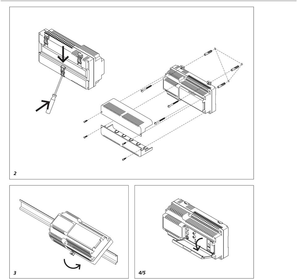
6 The term conductor length / range refers to the entire laid length of conductor material including all branch feeders Power supply units must be distributed over the conductor network according to load. Conductor routing In order to fulfil the general safety requirements for telecommunication systems in accordance with VDE 0100 and VDE 0800 and to avoid interference, attention must be paid to separate laying of power and light current cables. Observe a spacing of 10 cm (3.9 in). Mounting 2 Surface mounting with accessory ZAP Important When of surface mounting, a protection against direct contact must be provided. The regulations of VDE 0100/DIN part 410 must be observed. 3 Mount the line rectifier on the top hat rail (distribution) 4 Commissioning The system can be commissioned qualified installation and address setting of the individual system components. Under the transparent cover, there are 3 LEDs Power (under current) ON Bus (Bus under current) and 2 push buttons on off Primary fuse S1 In addition, the connection of any external push buttons, using the terminals ext. on and ext. off, is possible (provide control device). All line rectifiers are connected to the mains in the primary circuit, i.e. the "power" LED lights up. 5 The cover is opened by pulling lightly with the fingers at the upper edge at the centre of the cover. By activating the ON key, all power supply units are switched to the same bus. At each power supply unit at this bus, all LEDs are now alight. The system is ready for operation as far as the power supply is concerned. By pressing the OFF key, the bus is switched off again, i.e. only the LED Power lights up. 6 Automatic ON function a By inserting a jumper from terminal 2 to ext. ON, the system automatically switches back again after a power failure. This jumper cancels the function of the push button. At least 1.5 seconds must pass between an ON switching pulse and an OFF switching pulse, otherwise the function is not executed. Important! A line rectifier is able to supply a maximum of 4 connection loads. For more than 4 connection loads, a further line rectifier is required for each started group of 4. Line rectifiers and NG must not be used simul-taneously in one system. One SIC =1 connection load One TLC =1 connection load One BC =0,5 connection load for local bus and 0,1 connection load for global bus. Technical specifications for Primary 230 V/50-60 Hz +6% -10% Secondary 27 V DC 0.5 A controlled (with max. load min. 26 V DC) Protection IP 20 Dimension 180 x 89 x 60 Weight 1.2 kg Technical specifications for NG Primary 120 V/60 Hz, +6% -10% Secondary 27 V DC 0.5 A controlled (with max. load min. 26 V DC) Protection IP 20 Dimension 180 x 89 x 60 Weight 1.2 kg Comment The 120 V version NG must be operated in a closed circuit box only. Covering only with ZAP is not enough. The 120 V version must only be used in conjunction with ITE devices. (Information Technology Equipment) 5

PROFIBUS-DP Repeater 1 to 1 and 1 to 5 with optional level converter module
 LSS PROFIBUS-DP Repeater 1 to 1 and 1 to 5 with optional level converter module The LSS PROFIBUS-DP repeaters 1 to 1 and 1 to 5 are used for coupling up to six PROFIBUS bus segments in RS 485 bus technology.
Funktionsbeschreibung/ Montageanweisung Steuermodul DSM 400 für Dunstabzugshaube DA 6000 W
 Funktionsbeschreibung/ Montageanweisung Steuermodul DSM 400 für Dunstabzugshaube DA 6000 W Operation/Installation Control module DSM 400 for Cooker Hood DA 6000 W de, en M.-Nr. 09 165 660 Inhalt/Contents
Ex-Barriere für Diagnoseeinheit SITRANS DA400 / Ex-barrier for diagnostics unit SITRANS DA400 7MJ2010-1AA 0032
 Ex-Barriere für Diagnoseeinheit SITRANS DA400 / Ex-barrier for diagnostics unit SITRANS DA400 7MJ2010-1AA 0032 Warnung Elektrischer Anschluss in explosionsgefährdeten Bereichen Anschluss und Inbetriebnahme
Power supply Interference suppressed acc. to DIN EN /- 4, EN 55011, EN CI. B, power factor corrected Power factor BöSha LED driver
 Operating Instructions LED Mast Double Luminaire Callisto SC DB, incl. Inclination Adjustment, Single-Chip Technology (Please, read carefully before starting operation) Version: 16.01.2017 Model 369-M
UWC 8801 / 8802 / 8803
 Wandbedieneinheit Wall Panel UWC 8801 / 8802 / 8803 Bedienungsanleitung User Manual BDA V130601DE UWC 8801 Wandbedieneinheit Anschluss Vor dem Anschluss ist der UMM 8800 unbedingt auszuschalten. Die Übertragung
Electrical tests on Bosch unit injectors
 Valid for Bosch unit injectors with order numbers 0 414 700 / 0 414 701 / 0 414 702 Parts Kit Magnet*: - F00H.N37.925 - F00H.N37.933 - F00H.N37.934 * For allocation to the 10-place Bosch order number,
ABB i-bus EIB. EIB Power Supply Units
 ABB i-bus EIB EIB Power Supply Units Product Range Overview EIB Power Supplies ABB STOTZ-KONTAKT GmbH, 2002 - SK 029 F 02 E Product Range Overview EIB Power Supplies! EIB Power Supply, 320 ma SV/S 30.320.5!
CONTROLLER RECEIVER REPEATER PAIRING SLIM CLIP
 ANLEITUNGEN // INSTRUCTIONS CONTROLLER RECEIVER REPEATER PAIRING SLIM CLIP BEDIENUNGSANLEITUNG // INSTRUCTION MANUAL MONTAGEANLEITUNG // ASSEMBLY INSTRUCTION MONTAGEANLEITUNG // ASSEMBLY INSTRUCTION KOPPLUNG
Serviceinformation Nr. 02/11
 Serviceinformation Nr. 02/11 vom: 06.10.2011 von: BAM 1. Software Navigator und Release Notes Auf unserer Homepage unter www.idm-energie.at/de/navigator-software.html steht ab sofort eine neue Version
RS232-Verbindung, RXU10 Herstellen einer RS232-Verbindung zwischen PC und Messgerät oder Modem und Messgerät
 Betriebsanleitung RS232-Verbindung, RXU10 Herstellen einer RS232-Verbindung zwischen PC und Messgerät oder Modem und Messgerät ä 2 Operating Instructions RS232 Connection, RXU10 Setting up an RS232 connection
Overview thermostat/ temperature controller
 Thermostat TR-238 The Thermostat TR-238 is a electronic two-level controller for controlling of and in climate control units and vehicles. Voltage range (12V): Voltage range (24V): Control range: Hystereses:
Electrical testing of Bosch common rail piezo injectors
 Applies to generation CRI 3: Bosch 10-position order number 0 445 115 = CRI 3-16 (CRI 3.0) 1600 bar 0 445 116 = CRI 3-18 (CRI 3.2) 1800 bar 0 445 117 = CRI 3-20 (CRI 3.3) 2000 bar Tools required: Hybrid
SYSTEM COMPONENTS FOR 3~ RECESSED TRACK STANDARD 3~ RECESSED TRACK STANDARD. 3~ Recessed Track Standard
 3~ RECESSED TRACK STANDARD Ceiling cut 40 59 3~ Recessed Track Standard 41 A 5-conductor recessed track with 3 separately switchable circuits and a data bus track. It consists of an extruded aluminum profile
Datenblatt. P-series PDU 2.5/4/4AN
 Turn five into three that's the winning formula of the new P series with the PUSH IN connection system in which the pitches for 2.5, 4, 6 and 10 mm² are each combined in one terminal block. That means
1. Komponenten des Bausatzes
 1. Komponenten des Bausatzes Der Teilesatz 0510 590044 besteht aus folgenden Komponenten. 1 x Halter für Lasermarkierungen 3 x Lasermarkierungsleuchten mit Positionshalter 1 x Anschlußleiste für Lasermarkierungen
miditech 4merge 4-fach MIDI Merger mit :
 miditech 4merge 4-fach MIDI Merger mit : 4 x MIDI Input Port, 4 LEDs für MIDI In Signale 1 x MIDI Output Port MIDI USB Port, auch für USB Power Adapter Power LED und LOGO LEDs Hochwertiges Aluminium Gehäuse
Snap-in switch for switches PSE, MSM and MCS 30
 Product manual Snap-in switch for switches PSE, MSM and MCS 30 CONTENTS 1. PRODUCT DESCRIPTION 2. DATA AND DIMENSIONAL DRAWINGS 2.1. Technical Data 2.2. Dimensions of PSE with a Mounting Diameter 19 mm
Softwareupdate-Anleitung // AC Porty L Netzteileinschub
 1 Softwareupdate-Anleitung // AC Porty L Netzteileinschub Softwareupdate-Anleitung // AC Porty L Netzteileinschub HENSEL-VISIT GmbH & Co. KG Robert-Bunsen-Str. 3 D-97076 Würzburg-Lengfeld GERMANY Tel./Phone:
Electrical testing of Bosch common rail Injectors
 Electrical testing of Bosch common rail Injectors Contents: 1. Adapter cable for Hybridtester FSA 050 (article number 0 684 010 050 / 1 687 023 571) 2. Electrical testing of Bosch common rail solenoid
CABLE TESTER. Manual DN-14003
 CABLE TESTER Manual DN-14003 Note: Please read and learn safety instructions before use or maintain the equipment This cable tester can t test any electrified product. 9V reduplicated battery is used in
Electrical testing of Bosch common rail solenoid valve (MV) injectors
 injectors") Applies to MV injector, generation: -CRI 1.0 / 2.0 / 2.1 / 2.2 -CRIN 1 / 2 / 3, with K oder AK plug Bosch 10-position order number Bosch-Bestellnummer CRI: 0 445 110 xxx Bosch-Bestellnummer CRIN: 0 445
Applies to MV injector, generation: -CRI 1.0 / 2.0 / 2.1 / 2.2 -CRIN 1 / 2 / 3, with K oder AK plug Bosch 10-position order number Bosch-Bestellnummer CRI: 0 445 110 xxx Bosch-Bestellnummer CRIN: 0 445
Produktinformation Access-Gateway. Product information Access gateway AGW 670-0
 Produktinformation Access-Gateway Product information Access gateway AGW 670-0 1 2 3 4 2 Deutsch Anwendung Access-Gateway zur physikalischen Trennung von 2 Netzwerken an einem Access-Server. Durch den
Wandarm inkl. Montagebox und Netzteil Wall bracket incl. installation box and power supply
 Wandarm inkl. Montagebox und Netzteil Wall bracket incl. installation box and power supply Beschreibung und technische Daten: Wandarm (IP-66) mit Montagebox und eingebautem Netzteil Passend für SANTEC
Hazards and measures against hazards by implementation of safe pneumatic circuits
 Application of EN ISO 13849-1 in electro-pneumatic control systems Hazards and measures against hazards by implementation of safe pneumatic circuits These examples of switching circuits are offered free
rot red braun brown rot red RS-8 rot red braun brown R S V~
 Kleiner Ring 9 /Germany Phone: 0049 4122 / 977 381 Fax: 0049 4122 / 977 382 Sample connections: Feedback module with integrated detection of occupied tracks for the RS-feedback bus (Lenz Digital plus)
EMCO Installationsanleitung Installation instructions
 EMCO Installationsanleitung Installation instructions Installationsanleitung Installation instructions Digitalanzeige digital display C40, FB450 L, FB600 L, EM 14D/17D/20D Ausgabe Edition A 2009-12 Deutsch...2
Cameraserver mini. commissioning. Ihre Vision ist unsere Aufgabe
 Cameraserver mini commissioning Page 1 Cameraserver - commissioning Contents 1. Plug IN... 3 2. Turn ON... 3 3. Network configuration... 4 4. Client-Installation... 6 4.1 Desktop Client... 6 4.2 Silverlight
Kurzanleitung um Transponder mit einem scemtec TT Reader und der Software UniDemo zu lesen
 Kurzanleitung um Transponder mit einem scemtec TT Reader und der Software UniDemo zu lesen QuickStart Guide to read a transponder with a scemtec TT reader and software UniDemo Voraussetzung: - PC mit der
Aufbaudose mit Schalter Spacing box with switch. Montageanleitung mounting instructions
 Aufbaudose mit Schalter Spacing box with switch Montageanleitung mounting instructions body head Aufbaudose mit Schalter Montageanleitung S. 2 mounting instructions p. 9 $ 0.2m Sicherheitshinweise Die
Kuhnke Technical Data. Contact Details
 Kuhnke Technical Data The following page(s) are extracted from multi-page Kuhnke product catalogues or CDROMs and any page number shown is relevant to the original document. The PDF sheets here may have
Honeywell AG Hardhofweg. D-74821 Mosbach MU1H-1220GE23 R1001
 BA 95 Einbau-Anleitung Installation Instructions Einbau Installation Einbaubeispiel Installation example Ablaufleitung vorsehen Install discharge pipework Durchflussrichtung beachten! Consider direction
Datasheet. Page 1 of 7
 Features 20 Encoder Positions 4-way Joystick LED-Illumination high quality signal processing Benefits Tactile multi purpose application premium design Hall Effect technology Applications Multiple switch
MultiPortSwitch. VGA Umschalter. Version 1.0 As of April 19 th 2004 Subject to change!
 MultiPortSwitch VGA Umschalter Version 1.0 As of April 19 th 2004 Subject to change! Document version: Version Date Name Comment 1.00 29.03.2004 J. Klein Compiled Distributed by: idata industrielle Datensysteme
TECHNOLOGY MADE IN ITALY ÖLKÜHLER OIL COOLERS
 TECHNOLOGY MADE IN ITALY ÖLKÜHLER OIL COOLERS 113 ÖLKÜHLER - AIR/OIL COOLERS ALUMINIUM ALUMINUM Typ Models Öldurchfluss Oil flow capacity Lüfter Fan Kühlleistung Performance (40 C) Arbeits-- druck Pressure
Viatron GmbH Installationsanleitung KNX IR Linker
 Viatron GmbH Installationsanleitung KNX IR Linker Viatron GmbH Carl-Metz-Str. 3 76275 Ettlingen Tel.: +49 7243 5148 370 Fax: +49 7243 5148 351 Email: info@viatron.de Seite 1 von 5 Installationsanleitung
EINBAUHINWEISE INSTALLATION INSTRUCTIONS
 EINBAUHINWEISE INSTALLATION INSTRUCTIONS FÜR JEDEN ANSPRUCH DAS RICHTIGE FAHRWERK. KW automotive GmbH Aspachweg 14 74427 Fichtenberg Telefon: +49 7971 9630-0 Telefax: +49 7971 9630-191 www.kwsuspensions.de
Netzgerät compact Power Supply Unit compact 9.3389.10.010
 THE WORLD OF WEATHER DATA - THE WORLD OF WEATHER DATA - THE WORLD OF WEATHER DATA Bedienungsanleitung Instruction for use 021529/02/07 Netzgerät compact Power Supply Unit compact 9.3389.10.010 ADOLF THIES
 Information & Montageanleitung Information & Mounting instructions lassic Performance Premium 90 mm Module Halogen H7 12V ES / 1BL 009 999-... LES / EE 1ML 009 999-... US / SAE 1BL 009 999-... 24V ES /
Aufbau eines IT-Servicekataloges am Fallbeispiel einer Schweizer Bank
 SwissICT 2011 am Fallbeispiel einer Schweizer Bank Fritz Kleiner, fritz.kleiner@futureways.ch future ways Agenda Begriffsklärung Funktionen und Aspekte eines IT-Servicekataloges Fallbeispiel eines IT-Servicekataloges
Datenblatt. Remote-I/O - u-remote UR20-4AO-UI or 4-wire connection; 16-bit resolution; 4 outputs
 2- or 4-wire connection; 16-bit resolution; 4 outputs The analogue output module controls up to 4 analogue actuators with +/-10 V, +/-5 V, 0...10 V, 0...5 V, 2...10 V, 1...5 V, 0...20 ma or 4...20 ma with
HF13-Programm HF13 Programme
 S. 221 HF13 plugs S. 222 HF13-Adapter HF13 adapters S. 223 HF13-Buchsen s 2 HF13 - Programm Die HF-Steckverbindungen der Serie 13/4 werden in Anlagen der Nachrichtentechnik (DIN 47 283 und DIN 47 284),
Typenreihe GH Lifting Solenoids
 Hubmagnete Lifting Solenoids Bauart Hubmagnete der Reihe GH können mit Durchmessern zwischen 5 mm und 65 mm und mit Hublängen von 8 bis 60 mm gefertigt werden. Serien mäßig wer den sie mit Wellenenden
1 Allgemeine Information
 1 Allgemeine Information ACHTUNG! Der Betriebsdruck der Klasse 867 ist 6 bar. Sollte der Druck Ihrer Versorgungsleitung höher als 6 bar sein, muss der Druck an der Versorgungseinheit der Nähmaschine auf
Anschluss von Lithium-Ionen-Batterien an ein Sunny Backup System
 Sunny Backup-System SUNNY BACKUP 5000 SUNNY BACKUP 2200 Dieses Dokument gilt für folgende Backup-Wechselrichter: SBU 5000 ab Firmware-Version 7.0 Sicherheitshinweis Anschluss von Lithium-Ionen-Batterien
INSTALLATION AND OPERATING INSTRUCTIONS FOR imp1-xxxx-xxxx-xxxx-xxxx-xxxx-xxxx-xxxx-xx
 BEDIENUNGSANLEITUNG To comply with the published safety standards, the following must be observed when using this power supply. Um den zur Zeit gültigen Sicherheitsbestimmungen zu genügen, müssen die nachstehenden
Therefore the respective option of the password-protected menu ("UPDATE TUBE DATA BASE") has to be selected:
 has to be selected:") ENGLISH Version Update Dräger X-act 5000 ("UPDATE TUBE DATA BASE") The "BARCODE OPERATION AIR" mode is used to automatically transfer the needed measurement parameters to the instrument. The Dräger X-act
ENGLISH Version Update Dräger X-act 5000 ("UPDATE TUBE DATA BASE") The "BARCODE OPERATION AIR" mode is used to automatically transfer the needed measurement parameters to the instrument. The Dräger X-act
E/A-Bedieneinheit. I/O Control unit 658552 DE/GB 08/02
 E/A-Bedieneinheit I/O Control unit 527429 658552 DE/GB 08/02 Best.-Nr.: 658552 Benennung: DATENBLATT Bezeichnung: D:LP-BED.EINH.-E/A-DE/GB Stand: 08/2002 Autoren: Christine Löffler Grafik: Doris Schwarzenberger
VIDEO CALL CAMERA G-VCAM-01
 VIDEO CALL CAMERA G-VCAM-01 EN AUS GUTEM GRUND ENGLISH 07-10 2 SAFETY AND INFORMATION Safety 7 This camera is designed to transmit video and audio signals. All other uses are expressly prohibited. 7 Protect
(825M) 2-Draht-Sender
 2-Draht-Sender") Kamera SKS Bussystem 300004 (825M) 2-Draht-Sender 1. Installation Gefahr für Personen durch einen elektrischen Schlag. Verbrennungsgefahr, Geräteschäden und Fehlfunktionen. Bei der Installation sind die
Kamera SKS Bussystem 300004 (825M) 2-Draht-Sender 1. Installation Gefahr für Personen durch einen elektrischen Schlag. Verbrennungsgefahr, Geräteschäden und Fehlfunktionen. Bei der Installation sind die
Typenreihe GH Lifting Solenoids
 Hubmagnete Lifting Solenoids Bauart Hubmagnete der Reihe GH können mit Durchmessern zwischen 5 mm und 65 mm und mit Hublängen von 8 bis 60 mm gefertigt werden. Serien mäßig wer den sie mit Wellenenden
TECHNISCHE DATEN Leistungsrelais Zweispuliges TECHNICAL DATA Power Relay Dual-coil
 TECHNISCHE DATEN Leistungsrelais Zweispuliges TECHNICAL DATA Power Relay Dual-coil Seite Modell Bauart Funktion Dauerstrom Elektrischer Anschluß Page Model Design Function Duty rating Electrical link 2-3
BZ 873. Trainline Interface. Ident Nr.: 3EH-116802 R0001
 Ident Nr.: 3EH-116802 R0001 CH-8108 Dällikon Tel: +41(0)44 8440355 www.bahnelektronik.ch Seite: 1/8 Dritte oder andere Verwertung dieses Dokumentes sind ohne unsere ausdrückliche Zustimmung verboten. B+Z
LED Treiber: Anschlussschemata LED driver: connection diagrams
 Treiber: Anschlussschemata driver: connection diagrams TCI DC MAXI JOLLY DALI für 18W (Konstantstromversorgung), 500mA, dimmbar via Taster (Push) / 1-10V / DALI 6Z1851 Sicherheitshinweise Montagehinweise
MobiDM-App Handbuch für Windows Mobile
 MobiDM-App Handbuch für Windows Mobile Dieses Handbuch beschreibt die Installation und Nutzung der MobiDM-App für Windows Mobile Version: x.x MobiDM-App Handbuch für Windows Mobile Seite 1 Inhalt 1. WILLKOMMEN
Hama GmbH & Co KG Postfach Monheim/Germany Tel. +49 (0)9091/502-0 Fax +49 (0)9091/
9091/502-0 Fax +49 (0)9091/") www.hama.de Hama GmbH & Co KG Postfach 80 86651 Monheim/Germany Tel. +49 (0)9091/502-0 Fax +49 (0)9091/502-274 hama@hama.de www.hama.de 00062249-05.05 Multimedia Kit für/for Mercedes Command 2.0 00062249
www.hama.de Hama GmbH & Co KG Postfach 80 86651 Monheim/Germany Tel. +49 (0)9091/502-0 Fax +49 (0)9091/502-274 hama@hama.de www.hama.de 00062249-05.05 Multimedia Kit für/for Mercedes Command 2.0 00062249
INSTALLATION AND OPERATING INSTRUCTIONS FOR LPS203-M LPS203-M 操 作 指 示
 BEDIENUNGSANLEITUNG To comply with the published safety standards, the following must be observed when using this power supply. Um den zur Zeit gültigen Sicherheitsbestimmungen zu genügen, müssen die nachstehenden
A" " Anwendungshinweis 24V DC 01 ' "
 Um bei Schützen mit elektronischem 24V DC-Antrieb fehlerhafte Betriebszustände zu verhindern, die durch zu grosse Spannungseinbrüche verursacht werden, soll dem Anwender die Dimensionierung der Steuerspannungsquelle
Data-S EASY VERSTREUTE ÜBERWACHUNG DER NOTBELEUCHTUNG
 Abmessungen Dimensions 252x462x99 IP40 Data-S EASY VERSTREUTE ÜBERWACHUNG DER NOTBELEUCHTUNG Das System überwacht korrekten Betrieb der in kleinen und mittelgroßen Objekten der öffentlichen Nutzung installierten
4.) Geben Sie im Feld Adresse die IP Adresse des TDC Controllers ein. Die Standard Adresse lautet 192.168.1.50.
 Geben Sie im Feld Adresse die IP Adresse des TDC Controllers ein. Die Standard Adresse lautet 192.168.1.50.") Netzwerk: 1.) Kopieren Sie die Datei C30remote.exe von der Installations CD auf ihre Festplatte. 2.) Starten Sie die Datei C30remote.exe auf ihrer Festplatte. 3.) Wählen Sie aus dem Menü Verbindung den
Netzwerk: 1.) Kopieren Sie die Datei C30remote.exe von der Installations CD auf ihre Festplatte. 2.) Starten Sie die Datei C30remote.exe auf ihrer Festplatte. 3.) Wählen Sie aus dem Menü Verbindung den
JX3-PS1. Installationsanleitung. Version Lieferumfang
 JX3-PS1 Spannungsversorgungsmodul Jetter AG Kontakte: Gräterstraße 2 E-Mail - Vertrieb: sales@jetter.de D-71642 Ludwigsburg E-Mail - Hotline: hotline@jetter.de Germany Telefon - Hotline: +49(0)7141/2550-444
VDE Prüf- und Zertifizierungsinstitut Zeichengenehmigung
 2 Dieses Blatt gilt nur in Verbindung mit Blatt 1 des sausweises Nr. This supplement is only valid in conjunction with 1 of the. Schaltschrank-Heizelement Switch cabinet heating element mit Lüfter with
KURZANLEITUNG. Firmware-Upgrade: Wie geht das eigentlich?
 KURZANLEITUNG Firmware-Upgrade: Wie geht das eigentlich? Die Firmware ist eine Software, die auf der IP-Kamera installiert ist und alle Funktionen des Gerätes steuert. Nach dem Firmware-Update stehen Ihnen
Preisliste für The Unscrambler X
 Preisliste für The Unscrambler X english version Alle Preise verstehen sich netto zuzüglich gesetzlicher Mehrwertsteuer (19%). Irrtümer, Änderungen und Fehler sind vorbehalten. The Unscrambler wird mit
LED Treiber: Anschlussschemata LED driver: connection diagrams
 ED Treiber: Anschlussschemata ED driver: connection diagrams TCI DC JOY MD für 18W ED (Konstantstromversorgung), 500mA, dimmbar via Phasenabschnittsdimmer / Taster (Push) 6Z 18 50 Sicherheitshinweise Montagehinweise
Serviceinformation Nr. 05/10
 Serviceinformation Nr. 05/10 vom: 05.08.2010 von: GRC 1. Strömungswächter für Grundwasseranlagen Ab sofort können anstelle der Seikom Strömungswächter GF Schwebekörper Durchflussmesser mit Reed Kontakt
Parameter-Updatesoftware PF-12 Plus
 Parameter-Updatesoftware PF-12 Plus Mai / May 2015 Inhalt 1. Durchführung des Parameter-Updates... 2 2. Kontakt... 6 Content 1. Performance of the parameter-update... 4 2. Contact... 6 1. Durchführung
i500 Sicherheitsmodul I5MASA000 I5MASA000 safety module Montageanleitung Mounting Instructions
 i500 Sicherheitsmodul I5MASA000 Montageanleitung I5MASA000 safety module Mounting Instructions Allgemeines Erst lesen, dann beginnen 1 1 Allgemeines 1.1 Erst lesen, dann beginnen Lesen Sie vor der Installation
Produktdatenblatt. Artikel Nr.: Wandaufbauleuchte, Alpha II, Weiß, V AC/50-60Hz, 100,00 W. Technische Daten.
 Produktdatenblatt Artikel Nr.: 341107 Wandaufbauleuchte, Alpha II, Weiß, 220-240V AC/50-60Hz, 100,00 W Technische Daten Charakteristik Material Farbe Weiß Optik im Lieferumfang Elektrische Daten Leistung
Anwendungsbeispiele Verstärker Application Examples Amplifiers
 Anwendungsbeispiele Verstärker Application Examples Amplifiers Anwendungsbeispiele Application examples Multimedia-Verteilung in Sternstruktur über Abzweiger Multimedia distribution in star structure
DATENBLATT / DATASHEET
 DATENBLATT / DATASHEET AEQUILUX DMX PLAYER 1024 / 2048 Abb. Ähnlich Illustration similar BESCHREIBUNG / DESCRIPTION Der AEQUILUX DMX Player dient zur Lichtsteuerung des AEQUILUX Systems. Das Gerät kann
Zusatz zur Betriebsanleitung Addendum to the Operating Instructions
 Drive Technology \ Drive Automation \ System Integration \ Services Zusatz zur Betriebsanleitung Addendum to the Operating Instructions Austausch von MOVIGEAR -S01 durch MOVIGEAR -DSC-B Replacing MOVIGEAR
DATENBLATT / FACT SHEET
 DATENBLATT / FACT SHEET ART.-NR: WHISKY SODA LED WANDLEUCHTE / WALL LUMINAIRE LED.next Außenwandaufbauleuchte zur akzentuierten Beleuchtung von Fassaden und gebäudenahen Wegen. Gehäuse aus Aluminiumguss,
roll-up SONJA powerdisplays Aufbauanleitung Assemble instructions
 powerdisplay SONJA Mit Rollfunktion! Die Werbefläche rollt sich vollständig in das Display. So ist Ihre Werbung geschützt und in Sekunden wieder aufgebaut. Farbe: chrom/silber inkl. Tasche With rolling
Umschaltadapter/ Changeover / Trennadapter Disconnection Adapter für LSA-PLUS NT for LSA-PLUS NT. Montageanweisung Mounting Instructions
 Umschaltadapter/ Changeover / Trennadapter Disconnection Adapter für LSA-PLUS NT for LSA-PLUS NT Montageanweisung Mounting Instructions Der Umschalter dient zum unterbrechungsfreien Umschalten von Installations-drähten
p^db=`oj===pìééçêíáåñçêã~íáçå=
 p^db=`oj===pìééçêíáåñçêã~íáçå= Error: "Could not connect to the SQL Server Instance" or "Failed to open a connection to the database." When you attempt to launch ACT! by Sage or ACT by Sage Premium for
LED Treiber: Anschlussschemata LED driver: connection diagrams
 ED Treiber: Anschlussschemata ED driver: connection diagrams TCI DC JOY MD für 18W ED (Konstantstromversorgung), 500mA, dimmbar via Phasenabschnittsdimmer / Taster (Push) 6Z 18 50 Sicherheitshinweise Montagehinweise
FIRMWARE UPDATE TAPMOTION TD
 FIRMWARE UPDATE TAPMOTION TD CMP-SPF TO WHOM IT MAY CONCERN Seite 1 von 9 Inhalt / Overview 1. Firmware überprüfen und Update-file auswählen / Firmware check and selection of update file 2. Update File
Lukas Hydraulik GmbH Weinstraße 39 D Erlangen. Mr. Sauerbier. Lukas Hydraulik GmbH Weinstraße 39 D Erlangen. edraulic rescue equipment
 Technical Report No. 028-7130 95685-050 of 22.02.2017 Client: Lukas Hydraulik GmbH Weinstraße 39 D-91058 Erlangen Mr. Sauerbier Manufacturing location: Lukas Hydraulik GmbH Weinstraße 39 D-91058 Erlangen
Control Units CU240S Power Modules PM250 / PM260
 s Product Information Control Units CU240S Power Modules PM250 / PM260 Edition 11/2006 A5E01006377A Overview This product information sheet describes the behavior of inverters with Control Units CU240S
KIP Druckerstatus Benutzerhandbuch KIP Druckerstatus Installations- und Benutzerhandbuch
 KIP Druckerstatus Installations- und Benutzerhandbuch - 1 - Inhalt 1 Einführung... 3 2 Installation und Einrichtung... 4 3 Funktionalität des KIP Druckerstatus... 6 4 Benutzung des KIP Druckerstatus...
Output Choke Installation Instructions
 L Output Choke Installation Instructions C I N B F G E C B J H I Ground A D Wire and Terminal Torques - Field Wiring Connectors 2 A H Frame 3TC00-4AD1 3TC01-0BD0 3TC03-2CD0 Tightening Torque (Nm) 1.1 1.5
USBASIC SAFETY IN NUMBERS
 USBASIC SAFETY IN NUMBERS #1.Current Normalisation Ropes Courses and Ropes Course Elements can conform to one or more of the following European Norms: -EN 362 Carabiner Norm -EN 795B Connector Norm -EN
Installation Instructions
 EN DE Installation Instructions WLAN Installation Kit, 300 Mbps, 5 GHz, 16 dbi AK-4 Wireless Kit Scope of delivery Junction box AK-4 (1x) 1 Connection board AK-4 CB with 12VDC power supply unit (1x) 2
Schaltfunktion function. piping. Technische Änderungen vorbehalten / modifications reserved Stand / stand: 07/2012
 fremdgesteuert externally controlled Schaltfunktion function Elektrischer Anschluss M12x1 electrical connector M12x1 Die Ventile arbeiten als Druckwaage und werden im Bypass eingesetzt. Der Mediumsdruck
HEAG 151, 152, 153, 154 Digital Converter
 Montage- und Betriebsanleitung Installation and operating instructions MB095-11055704 Baumer_HEAG151-152-153-154_II_DE-EN (16A1) HEAG 151, 152, 153, 154 Digital Converter 1-2 Allgemeine Hinweise - Funktionsweise
LED Konverter: Anschlussschemata LED converter: connection diagrams
 LED Konverter: Anschlussschemata LED converter: connection diagrams TCI DC MAXI JOLLY DALI 48V DC, 48W (Konstantspannungsversorgung), dimmbar via Taster (Push) / 1-10V / DALI 6Z 48 10 00 Sicherheitshinweise
Installationsanleitung / installation manual - DIMMbox
 Inhalt / Content Funktionsbeschreibung... 2 Anschlusskonfigurationen... 3 Konstantspannung... 3 Konstantstrom... 3 Art der Steuerung... 4 Analogeingang... 4 Digital Addressable Lighting Interface (DALI):...
I-Energieversorgung I-Power Supply
 F Seite 1 page 1 1) Pneumatisch a. Stellantriebe mit Membrane finden ihren Einsatz da, wo kleine Stellkräfte ausreichen. Der pneumatische Stellantrieb ist direkt in Kompaktbauweise mit dem Stellventil
Leister SYSTEM SINGLE PATCH MODULE SPM 01
 D GB Leister SYSTEM SINGLE PATCH MODULE SPM 01 Leister Process Technologies Galileo-Strasse 10 CH-05 Kaegiswil/Switzerland Tel. +41-41 4 4 Fax +41-41 4 1 www.leister.com sales@leister.com Einbauanleitung
https://portal.microsoftonline.com
 Sie haben nun Office über Office365 bezogen. Ihr Account wird in Kürze in dem Office365 Portal angelegt. Anschließend können Sie, wie unten beschrieben, die Software beziehen. Congratulations, you have
Word-CRM-Upload-Button. User manual
 Word-CRM-Upload-Button User manual Word-CRM-Upload for MS CRM 2011 Content 1. Preface... 3 2. Installation... 4 2.1. Requirements... 4 2.1.1. Clients... 4 2.2. Installation guidelines... 5 2.2.1. Client...
Montage-Anschluss-Anleitung
 Montage-Anschluss-Anleitung Verteiler-Modul BUS-1 Art.-Nr. 010116.17 1. Allgemeines Das Verteiler-Modul 010116.17 ermöglicht den sternförmigen Anschluss mehrerer BUS 1-Leitungen an einem Verteilerpunkt.
Aufgabenstellung Mit welchen SICLOCK Produkten kann ich einen PC Zeitsynchronisieren?
 SICLOCK Application Note AN-0005 Titel Synchronisation von PCs mit SICLOCK Aufgabenstellung Mit welchen SICLOCK Produkten kann ich einen PC Zeitsynchronisieren? Schlüsselwörter SICLOCK DCFRS, WinGPS, GPS1000,
ADVERTISING IMAGES ANZEIGENMOTIVE. Spring/Summer 2014 Frühjahr/Sommer 2014
 ADVERTISING IMAGES ANZEIGENMOTIVE Spring/Summer 2014 Frühjahr/Sommer 2014 Content/Inhalt Collections advertising images Collections Anzeigenmotive 4-7 Sports advertising images Sports Anzeigenmotive 8-9
EINBAUHINWEISE INSTALLATION INSTRUCTIONS
 EINBAUHINWEISE INSTALLATION INSTRUCTIONS FÜR JEDEN ANSPRUCH DAS RICHTIGE FAHRWERK. KW automotive GmbH Aspachweg 14 74427 Fichtenberg Telefon: +49 7971 9630-0 Telefax: +49 7971 9630-191 www.kwsuspensions.de
Alpha 2T EINBAUANLEITUNG MOUNTINGINSTRUCTIONS
 Alpha 2T EINBAUANLEITUNG MOUNTINGINSTRUCTIONS Installation der Antennenanlage Alpha 2T Die Antennenanlage Alpha 2T besteht aus der Antenne Alpha 2T und dem Antennenverteiler DB1C. Standort der Antenne
Contact 1600 QUICK REFERENCE GUIDE GUIDE D UTILISATION BEDIENUNGSANLEITUNG GUÍA DE REFERENCIA RÁPIDA GUIDA RAPIDA. www.sonybiz.net CHANGING THE WAY
 Contact 1600 CHANGING THE WAY QUICK REFERENCE GUIDE GUIDE D UTILISATION BEDIENUNGSANLEITUNG BUSINESS GUÍA DE REFERENCIA RÁPIDA GUIDA RAPIDA COMMUNICATES www.sonybiz.net GB Getting started STEP 1 Turning